

Page 1
TI01350T/09/EN/02.18
71418574
2018-11-05
Products Solutions Services
Technical Information
iTHERM TT412
Thermometer protection tube for hygienic and
aseptic applications
Applications
• Specially designed for use in hygienic and aseptic applications in the
Food & Beverages and Life Sciences industries
• Pressure range up to 40 bar (580 psi)
• For increased protection requirements of the temperature sensor regarding
physical and chemical effects
• For use in pipes and containers or tanks
• Ideally suited to all measuring points that require regular recalibration by simply
replacing the insert in closed processes
Your benefits
• iTHERM QuickNeck – cost and time savings thanks to simple, tool-free
recalibration of the insert used
• All common hygienic process connections
• International certification: 3-A Sanitary Standard, EHEDG, ASME BPE, FDA, TSE
Certificate of Suitability
• Fast response time owing to reduced tips with thin walls
Page 2

Table of contents
Installation ................................ 3
Orientation ................................. 3
Installation instructions ......................... 3
Process ................................... 5
Process temperature range ....................... 5
Thermal shock ............................... 5
Process pressure range .......................... 5
Medium - state of aggregation ..................... 5
Mechanical construction ...................... 6
Design, dimensions ............................ 6
Weight .................................... 7
Material ................................... 7
Surface roughness ............................. 7
Process connections ............................ 8
Tip shape .................................. 10
iTHERM TT412
Certificates and approvals ................... 11
CE mark ................................... 11
Hygiene standard ............................ 11
Other standards and guidelines ................... 11
Parts in contact with the medium .................. 11
CRN approval ............................... 11
Surface purity ............................... 11
Material resistance ........................... 11
Material certification .......................... 11
Protection tube testing and load capacity calculation ..... 11
Ordering information ....................... 12
Accessories ............................... 13
Device-specific accessories ...................... 13
Service-specific accessories ...................... 14
Documentation ............................ 14
2 Endress+Hauser
Page 3
iTHERM TT412
U
≥ 3°
≥ 3°
1
2
3
4
1 2
3
4
R0.4
R0.4
Pressure ring
Sensor with
milk pipe
connection
Sensor with Varivent
connection
Shaped
gasket
Companion
connection
O-ring
Groove
slip-on nut
Centering ring
Sealing
Companion
connection
Companion
connection
O-ring
Welding boss
Vessel wall
Installation
Orientation
Installation instructions
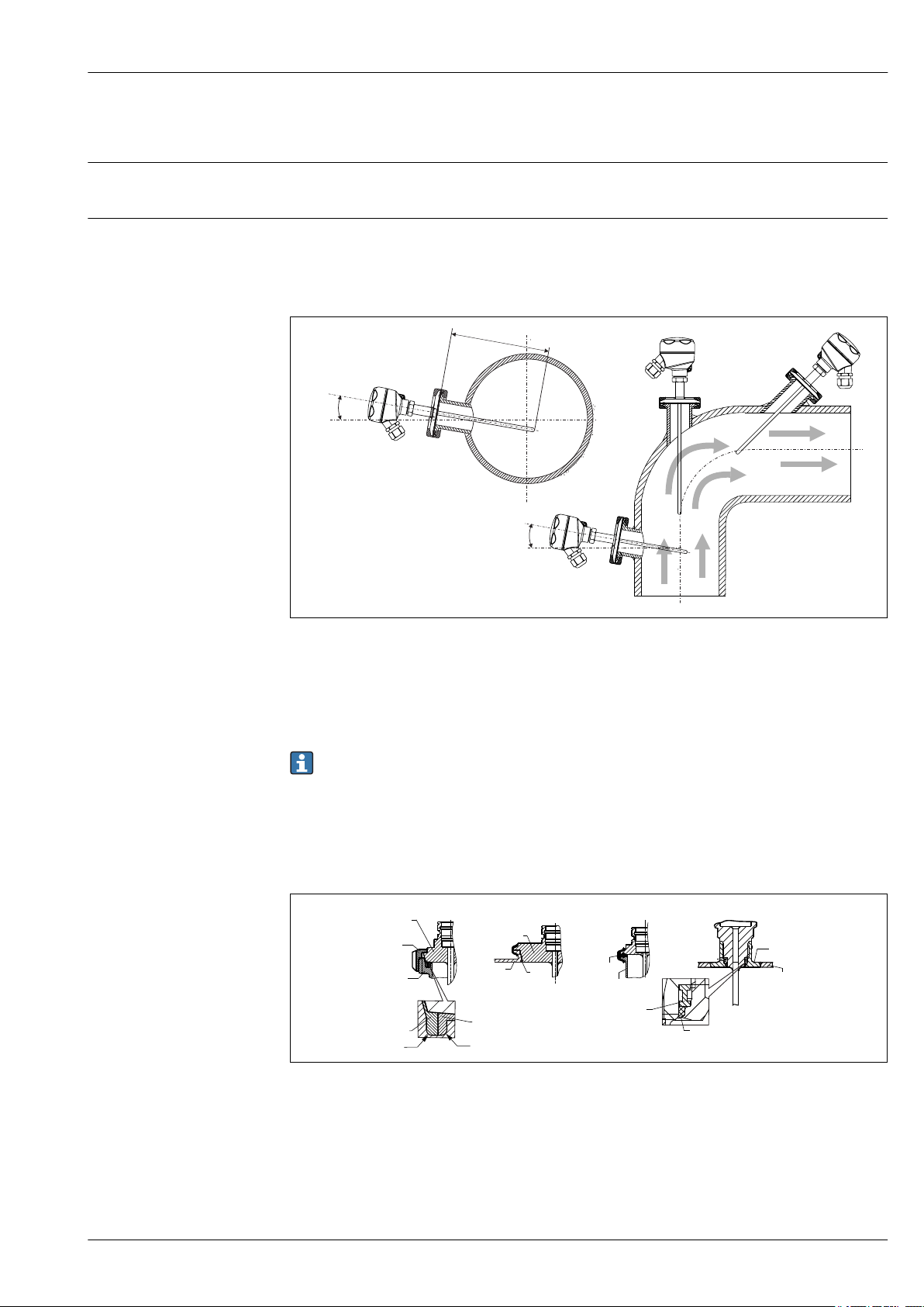
No restrictions. However, self-draining in the process must be guaranteed. If there is an opening to
detect leaks at the process connection, this opening must be at the lowest possible point.
The immersion length of the thermometer can influence the accuracy. If the immersion length is too
small then errors in the measurement are caused by heat conduction via the process connection. If
installing into a pipe then the immersion length should ideally be half of the pipe diameter.
Installation possibilities: Pipes, tanks or other plant components
A0008946
1 Installation examples
1, 2 Perpendicular to flow direction, installed at a minimum angle of 3° to ensure self-draining
3 On elbows
4 Inclined installation in pipes with a small nominal diameter
U Immersion length
Endress+Hauser 3
In the case of pipes with a small nominal diameter, it is advisable for the tip of the thermometer
to project well into the process so that it extends past the pipe axis. Installation at an angle (4)
could be another solution. When determining the immersion length or installation depth all the
parameters of the thermometer and of the medium to be measured must be taken into account
(e.g. flow velocity, process pressure).
The use of iTHERM QuickSens inserts is recommended for immersion lengths U <
70 mm (2.75 in).
2 Detailed installation instructions for hygiene-compliant installation
1 Sanitary connection according to DIN 11851, only in connection with EHEDG-certified and self-centering
sealing ring
2
Varivent® process connection for VARINLINE® housing
3 Clamp according to ISO 2852, only in connection with seal according to EHEDG position paper
4 Liquiphant-M G1" process connection
A0011758-EN
Page 4

iTHERM TT412
The counterpieces for the process connections and the seals or sealing rings are not included in
the scope of supply for the thermometer. Liquiphant M weld-in adapters with associated seal
kits are available as accessories.
Procedure in case of seal failure:
• Disassembling of the thermometer, validated cleaning procedure of thread and sealing ring
groove
• Replacement of the seal or sealing ring
• CIP after re-assembly
In the case of weld-in connections, exercise the necessary degree of care when performing the
welding work on the process side:
• Suitable welding material
• Flush-welded or with welding radius > 3.2 mm (0.13 in)
• No recesses, folds or gaps
• Honed and polished surface, Ra ≤ 0.76 µm (30 µin)
4 Endress+Hauser
Page 5
iTHERM TT412
L (mm)
A
0
10
20
30
40
50
60
70
80
90
100 200 300 400 500
v (m/s)
B
0
4 8 12 16 20
L (in)
0
30
65
100
130
160
200
230
260
290
v (ft/s)
Process
Process temperature range
Thermal shock
Process pressure range
Maximum –200 to +650 °C (–328 to +1 202 °F)→ 7
Thermal shock resistance in CIP/SIP process with a temperature increase from
+5 to +130 °C (+41 to +266 °F) within 2 seconds.
The maximum possible process pressure depends on various influencing factors, such as the design,
process connection and process temperature. For information on the maximum possible process
pressures for the individual process connections, see the 'Process connection' section. → 8
It is possible to check the mechanical loading capacity as a function of the installation and
process conditions online in the Thermowell (TW) Sizing Module for protection tubes in the
Endress+Hauser Applicator software. See 'Accessories' section.
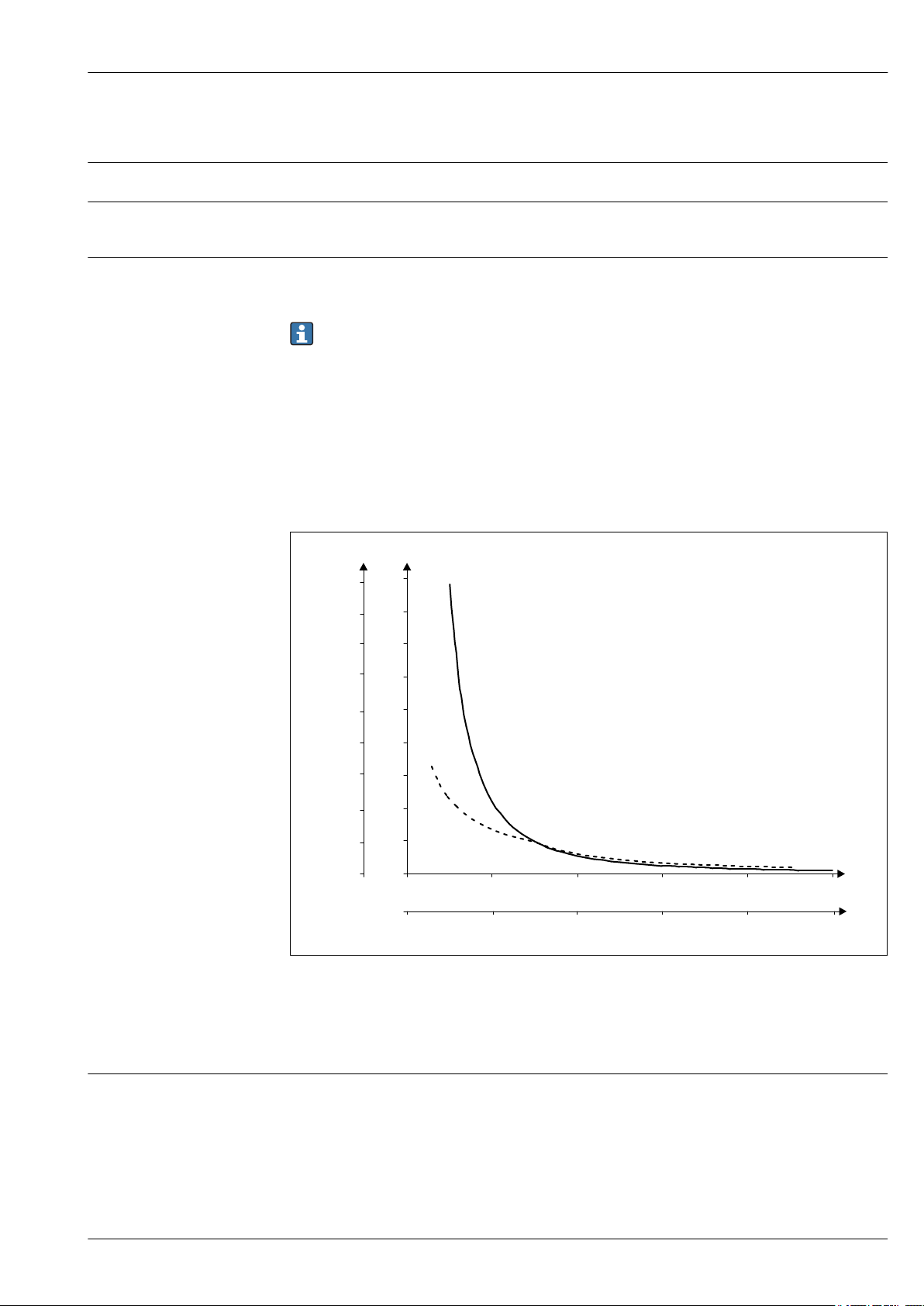
Example of the permitted flow velocity depending on the immersion length and process
medium
The highest flow velocity tolerated by the protection tube diminishes with increasing insert
immersion length exposed to the stream of the fluid. In addition, it is dependent on the diameter of
the tip of the protection tube, the medium type, process temperature and process pressure. The
following figures exemplify the maximum permitted flow velocities in water and superheated steam
at a process pressure of 40 bar (580 PSI).
3 Permitted flow velocities, protection tube diameter 9.53 mm (3/8 in)
A Medium water at T = 50 °C (122 °F)
B Medium superheated steam at T = 400 °C (752 °F)
L Immersion length exposed to flow
v Flow velocity
Medium - state of aggregation
Gaseous or liquid (also with high viscosity, e.g. yogurt).
Endress+Hauser 5
A0008967
Page 6
Mechanical construction
U
L
6.35
( )¼
4.76
(3/16)
NPT “½
B=3.2
(0.125)
1.75"+T
U
L
12.7
( )½
4.76
(3/16)
9.53
(3/8)
1
2
3
4
5
1 75 +. " T
iTHERM TT412
Design, dimensions
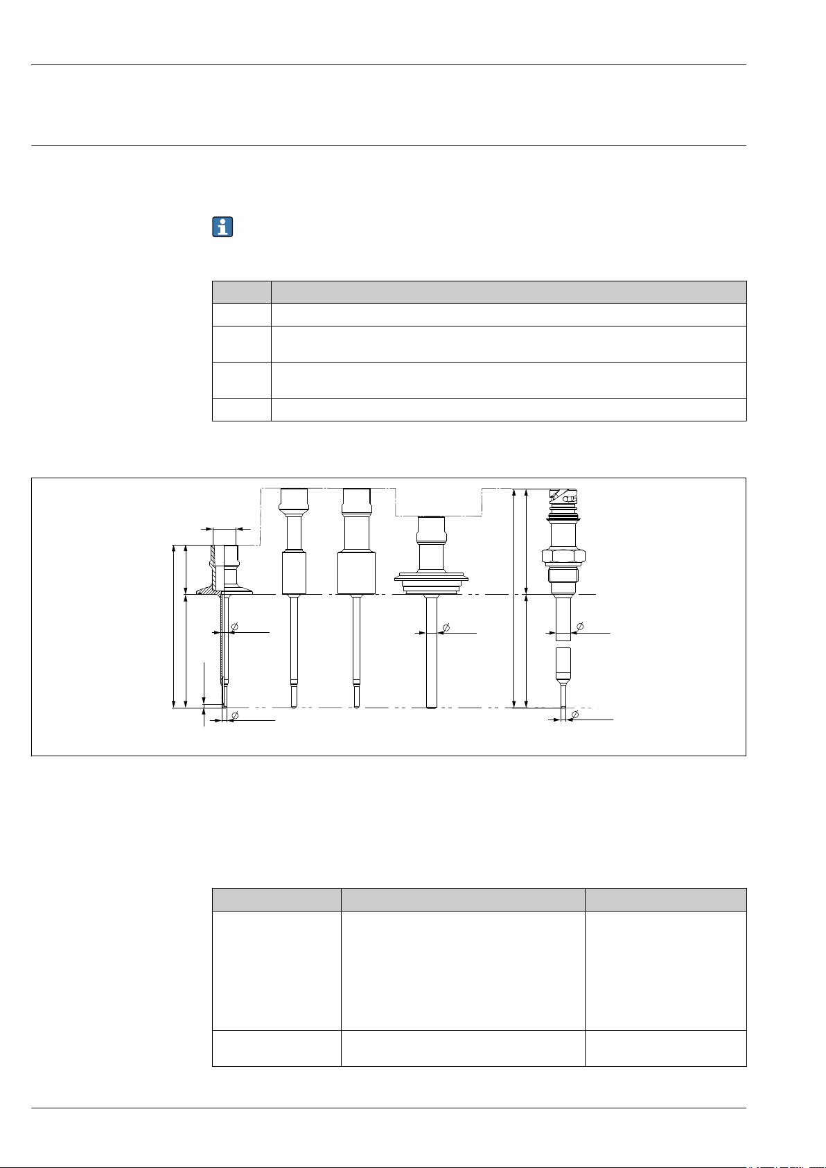
All dimensions in mm (in). The design depends on the protection tube version:
• Diameter 6.35 mm (¹⁄₄ in)
• Diameter 9.53 mm (³⁄₈ in)
• Diameter 12.7 mm (¹⁄₂ in)
Various dimensions, such as the immersion length U for instance, are variable values and are
therefore indicated as items in the following dimensional drawings.
Variable dimensions:
Item Description
L Protection tube length (U+T+1.75 ")
B Protection tube base thickness: predefined, depends on protection tube version (see also the
individual table data)
T Length of protection tube shaft: variable or predefined, depends on protection tube version (see
also the individual table data)
U Immersion length: variable, depending on the configuration
Protection tube diameter (1/4, 3/8, 1/2 in)
4 Protection tube with neck connection NPT 1/2" and various process connection versions:
1 Tri-clamp
2 Cylindrical weld-in adapter D 3/4" NPS
3 Cylindrical weld-in adapter D 1" NPS
4 Varivent®
5 Liquiphant adapter with QuickNeck
Item Version Length
Triclamp with NPT
Length of protection tube
1)
shaft T
6 Endress+Hauser
Immersion length U Independent of the version
Triclamp with QuickNeck
Varivent® with NPT
Varivent® with QuickNeck
Liquiphant with NPT
Liquiphant with QuickNeck
Weld-in with NPT
Weld-in with QuickNeck
0-6"
1-6"
1-6"
1.5-6"
2-6"
2-6"
2-6"
2-6"
Variable, depending on the
configuration
A0033718
Page 7

iTHERM TT412
Item Version Length
Base thickness B 6.35 mm (¹⁄₄ in) Protection tube:
Reduced tip 4.76 mm (³⁄₁₆ in)
9.53 mm (³⁄₈ in) Protection tube:
Reduced tip 4.76 mm (³⁄₁₆ in)
Straight tip
12.7 mm (¹⁄₂ in) Protection tube:
Reduced tip 4.76 mm (³⁄₁₆ in)
Straight tip
1) Depends on the process connection
3.2 mm (0.125 in)
3.2 mm (0.125 in)
3 mm (0.12 in)
3 mm (0.12 in)
6.3 mm (0.25 in)
Weight
Material
Surface roughness
0.3 to 2.5 kg (0.66 to 5.5 lbs) for standard options.
The temperatures for continuous operation specified in the following table are only intended as
reference values for use of the various materials in air and without any significant compressive load.
The maximum operating temperatures can be reduced considerably in cases where abnormal
conditions such as high mechanical load occur or in aggressive media.
Recommended max.
Designation
AISI 316L 650 °C (1 202 °F)
1) Can be used to a limited extent up to 800 °C (1472 °F) for low compressive loads and in non-corrosive
media. Contact your Endress+Hauser sales team for further information.
Values for wetted surfaces:
temperature for
continuous use in air
1)
1)
Properties
• Austenitic, stainless steel
• High corrosion resistance in general
• Particularly high corrosion resistance in chlorinebased and acidic, non-oxidizing atmospheres
through the addition of molybdenum (e.g.
phosphoric and sulfuric acids, acetic and tartaric
acids with a low concentration)
• Increased resistance to intergranular corrosion and
pitting
• The wetted part from a 316L or 1.4435+316L
thermowell withstand a passivation process with a
3% sulphuric acid
Standard surface Ra ≤ 0.76 µm (30 µin)
Finely honed surface
Finely honed surface and electropolished Ra ≤ 0.38 µm (15 µin)+ electropolished
1) Exception: Inside welding seams of the tee and elbow thermowells
2) Not compliant with ASME BPE
2)
Ra ≤ 0.38 µm (15 µin)
Endress+Hauser 7
Page 8
iTHERM TT412
U
!d
h
44.45 + T
(1.75")
!D
U
!d
!a
!d
U
!D
R1.2
R0.8
0.4
1.6
A
A: Tri-clamp
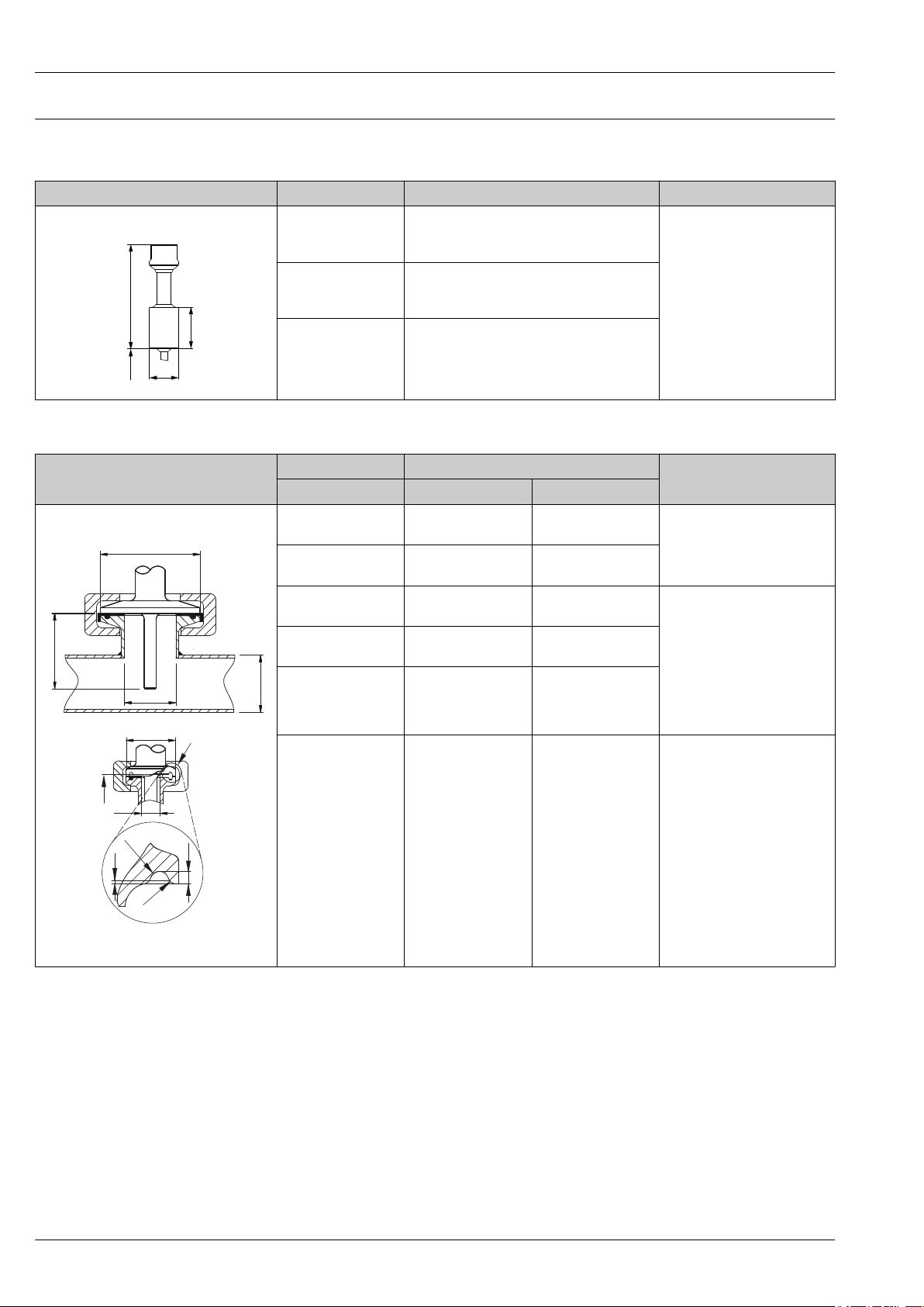
Process connections
All dimensions in mm (in).
For welding in
Type Version Dimensions Technical properties
Weld-in adapter
A0033743
Releasable process connection
Type
Clamp according to ASME BPE or ISO 2852
Cylindrical ½" NPS d = ½" NPS, h = 38.1 mm (1.5 in), U =
immersion length from lower edge of thread,
T = min. 50.8 mm (2 in)
Cylindrical ¾" NPS d = ¾" NPS, h = 38.1 mm (1.5 in), U =
immersion length from lower edge of thread,
T = min. 50.8 mm (2 in)
Cylindrical 1" NPS d = 1" NPS, h = 38.1 mm (1.5 in), U =
immersion length from lower edge of thread,
T = min. 50.8 mm (2 in)
Version Dimensions
1)
d:
Tri-clamp ¾"
(DN18)
2)
Clamp ISO 2852 ½"
(DN12 - 21.3)
Tri-clamp 1" - 1½"
(DN25 - 38)
Tri-clamp 2" (DN40 -
51)
Tri-clamp 2½"
(DN63.5)
Tri-clamp 3"
D a
25 mm (0.98 in) -
34 mm (1.34 in)
50.5 mm (1.99 in)
16 to 25.3 mm
(0.63 to 0.99 in)
29 to 42.4 mm
(1.14 to 1.67 in)
64 mm (2.52 in) 44.8 to 55.8 mm
(1.76 to 2.2 in)
77.5 mm (3.05 in) 68.9 to 75.8 mm
(2.71 to 2.98 in)
91 mm (3.58 in) > 75.8 mm (2.98 in) • P
(DN70-76.5)
• P
depends on the weld-in
max.
process
• With 3-A symbol and
EHEDG certification
• ASME BPE compliance
Technical properties
• P
= 16 bar (232 psi),
max.
depends on clamp ring and
suitable seal
• With 3-A symbol
• P
= 16 bar (232 psi),
max.
depends on clamp ring and
suitable seal
• With 3-A symbol and
EHEDG certification (sealing
according to EHEDG position
paper, DN25, DN40,
DN63,5)
• ASME BPE compliance
= 16 bar (232 psi),
max.
depends on clamp ring and
suitable seal
• With 3-A symbol
• ASME BPE compliance
3)
4)
A0033985
A Different seal geometries for Tri-clamp
1) Pipes in accordance with ISO 2037 and BS 4825 Part 1
2) Tri-clamp ¾" only possible with protection tube diameter 6.35 mm (¹⁄₄ in) or 9.53 mm (³⁄₈ in)
3) Not for DN12-21.3
4) Not for DN12-21.3
8 Endress+Hauser
Page 9
iTHERM TT412
U
L1
1
G
A
U
!D
!B
!A
h
U
!D
!i
!a
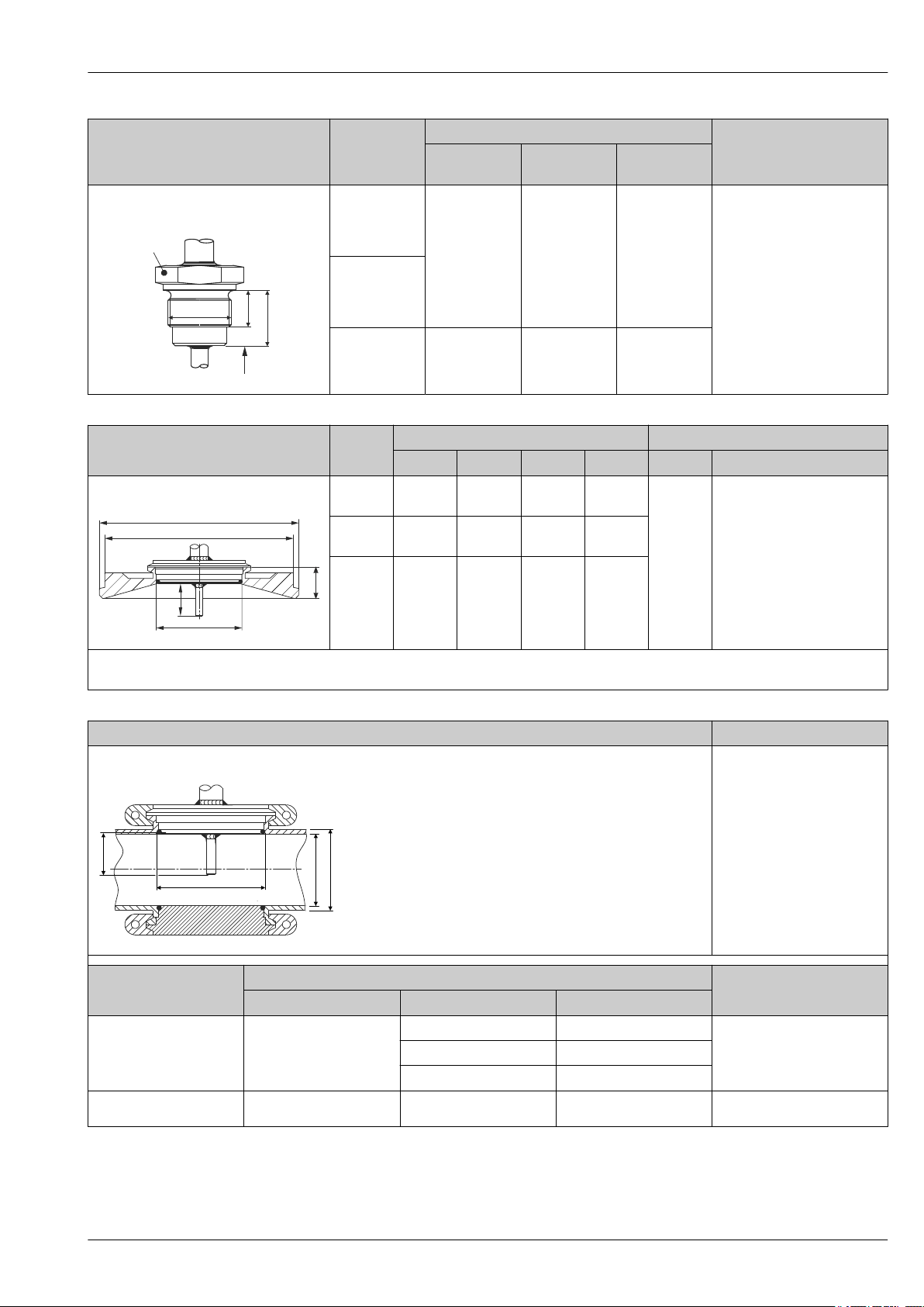
Type Version G
Thread according to ISO 228 (for
Liquiphant weld-in adapter)
A0009572
G¾" for FTL20
adapter
G¾" for FTL50
adapter
G1" for FTL50
adapter
L1 thread
length
16 mm
(0.63 in)
18.6 mm
(0.73 in)
Dimensions
A 1 (SW/AF)
25.5 mm (1 in) 32
29.5 mm
(1.16 in)
41
Technical properties
• P
= 25 bar (362 psi) at
max.
max. 150 °C (302 °F)
• P
= 40 bar (580 psi) at
max.
max. 100 °C (212 °F)
• In connection with
FTL31/33/50 adapter
3-A symbol and EHEDG
certification
• ASME BPE compliance
• Minimum extension neck
lengths: ≥ 76.2 mm (3 in)
Type Version
Dimensions Technical properties
D A B h P
®
Varivent
A0021307
The VARINLINE® housing connection flange is suitable for weld-in into the conical or torispherical head in tanks or containers with a small
diameter (≤ 1.6 m (5.25 ft)) and up to a wall thickness of 8 mm (0.31 in).
Type B 31 mm
(1.22 in)
Type F 50 mm
(1.97 in)
Type N 68 mm
(2.67 in)
105 mm
(4.13 in)
145 mm
(5.71 in)
165 mm
(6.5 in)
- 22 mm
135 mm
(5.31 in)
155 mm
(6.1 in)
(0.87 in)
24 mm
(0.95 in)
24.5 mm
(0.96 in)
max.
10 bar
(145 psi)
• With 3-A symbol and
EHEDG certification
• ASME BPE compliance
Type Technical properties
Varivent® for VARINLINE® housing for installation in pipes
• With 3-A symbol and
EHEDG certification
• ASME BPE compliance
A0009564
Dimensions
Version
D i a
P
max.
OD 1½": 34.9 mm (1.37 in) OD 1½": 38.1 mm (1.5 in)
Type N, according to DIN
11866, series C
68 mm (2.67 in)
OD 2": 47.2 mm (1.86 in) OD 2": 50.8 mm (2 in)
OD 1½" to OD 2½":
16 bar (232 psi)
OD 2½": 60.2 mm (2.37 in) OD 2½": 63.5 mm (2.5 in)
Type N, according to DIN
11866, series C
68 mm (2.67 in)
OD 3": 73 mm (2.87 in) OD 3": 76.2 mm (3 in)
OD 3" to OD 4": 10 bar (145 psi)
Endress+Hauser 9
Page 10
Type Technical properties
!7 (0.28)
3 (0.12)
!D2
!3.2
(0.13)
17 (0.67)
!D2
!3.2
(0.13)
3.2 (0.13)
6.3
!D2
2 31
!D1
!D1
!D1 =
!D2
!D1
!3.3
(0.13)
!6.6 (0.26)
!D1 =
!D2
17 (0.67)
3.2 (0.13)
17 (0.67)
3.2 (0.13)
Type F, according to DIN
11866, series C
OD 4": 97.6 mm (3.84 in) OD 4": 101.6 mm (4 in)
50 mm (1.97 in)
OD 1": 22.2 mm (0.87 in) OD 1": 25.4 mm (1 in)
16 bar (232 psi)
Due to the small immersion length U, the use of iTHERM QuickSens inserts is recommended.
iTHERM TT412
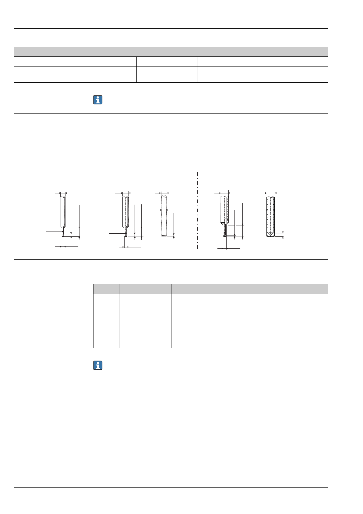
Tip shape
The thermal response time, the reduction of the flow cross-section and the mechanical load that
occurs in the process are the criteria that matter when selecting the shape of the tip. Advantages of
using reduced thermometer tips:
• A smaller tip shape has less impact on the flow characteristics of the pipe carrying the medium.
• The flow characteristics are optimized, thereby increasing the stability of the protection tube.
A0033991
5 Protection tube tips available (reduced or straight)
Item No. Protection tube (D1) Tip (D2) Insert (ID)
1 6.35 mm (¹⁄₄ in) Reduced tip with 4.76 mm (³⁄₁₆ in) 3 mm (0.12 in)
2 9.53 mm (³⁄₈ in)
3 12.7 mm (¹⁄₂ in)
• Reduced tip with 4.76 mm (³⁄₁₆ in)
• Straight tip
• Reduced tip with 4.76 mm (³⁄₁₆ in)
• Straight tip
• 3 mm (0.12 in)
• 6.35 mm (¹⁄₄ in) or
6 mm (0.24 in)
• 3 mm (0.12 in)
• 6.35 mm (¹⁄₄ in) or
6 mm (0.24 in)
It is possible to check the mechanical loading capacity as a function of the installation and
process conditions online in the TW Sizing Module for protection tubes in the Endress+Hauser
Applicator software. See 'Accessories' section. → 13
10 Endress+Hauser
Page 11

iTHERM TT412
Certificates and approvals
CE mark
Hygiene standard
Other standards and guidelines
Parts in contact with the medium
CRN approval
The product meets the requirements of the harmonized European standards. As such, it complies
with the legal specifications of the EC directives. The manufacturer confirms successful testing of the
product by affixing to it the CE-mark.
• EHEDG certification, type EL - CLASS I. Permitted process connections in accordance with EHEDG,
see 'Process connections' section → 8
• 3-A authorization no. 1144, 3-A sanitary standard 74-06. Permitted process connections in
accordance with 3-A, see 'Process connections' section → 8
• ASME BPE 2009, certificate of conformity can be ordered for indicated options
ASME PTC 19.3 TW-2010: thermowells
Parts of the thermometer in contact with the medium comply with the following European
regulations:
• (EC) No. 1935/2004, Article 3, paragraph 1, Articles 5 and 17 on materials and articles intended
to come into contact with food.
• (EC) No. 2023/2006 on good manufacturing practice for materials and articles intended to come
into contact with food.
• (EC) No. 10/2011 on plastic materials and articles intended to come into contact with food.
• FDA-compliant
• All product contact surfaces are produced without animal derived ingredients (ADI/TSE)
The CRN approval is only available for certain options of protection tubes. These will be marked and
shown during the configuration of this device.
Surface purity
Material resistance
Material certification
Protection tube testing and load capacity calculation
Free from oil and grease, optional
Material resistance - including housing - to the following cleaning agents/disinfectants from the
company Ecolab: P3-topax 66, P3-topactive 200, P3-topactive 500 and P3-topactive OKTO as well as
demineralized water.
The material certificate 3.1 (according to standard EN 10204) can be requested separately.
• Protection tube pressure tests are carried out in accordance with the specifications in DIN 43772.
With regard to protection tubes with reduced tip that do not comply with this standard, these are
tested using the pressure of corresponding straight protection tubes. Tests according to other
specifications can be carried out on request. The liquid penetration test verifies that there are no
cracks in the welded seams of the protection tube.
• PMI test, dye penetration test, TW welding, internal hydrostatic pressure, etc. each with inspection
certificate
• Load capacity calculation for the protection tube as per DIN43772
Endress+Hauser 11
Page 12

iTHERM TT412
Ordering information
Detailed ordering information is available from the following sources:
• In the Product Configurator on the Endress+Hauser website: www.endress.com -> Click "Corporate"
-> Select your country -> Click "Products" -> Select the product using the filters and search field ->
Open product page -> The "Configure" button to the right of the product image opens the Product
Configurator.
• From your Endress+Hauser Sales Center: www.addresses.endress.com
Product Configurator - the tool for individual product configuration
• Up-to-the-minute configuration data
• Depending on the device: Direct input of measuring point-specific information such as
measuring range or operating language
• Automatic verification of exclusion criteria
• Automatic creation of the order code and its breakdown in PDF or Excel output format
• Ability to order directly in the Endress+Hauser Online Shop
12 Endress+Hauser
Page 13
iTHERM TT412
Accessories
Various accessories, which can be ordered with the device or subsequently from Endress+Hauser, are
available for the device. Detailed information on the order code in question is available from your
local Endress+Hauser sales center or on the product page of the Endress+Hauser website:
www.endress.com.
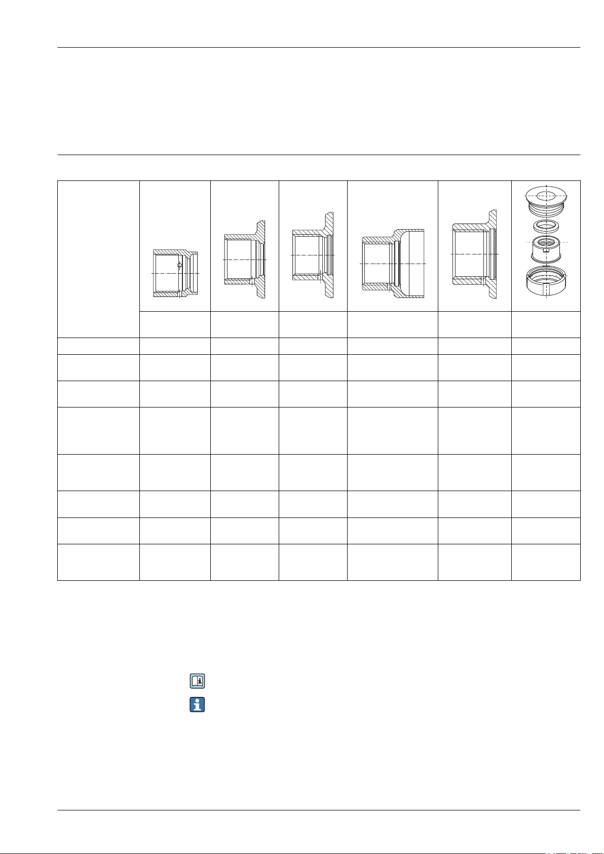
Device-specific accessories
Weld-in adapter
A0008246 A0008251 A0008256 A0011924 A0008248 A0008253
G ¾", d=29 for
pipe-mounting
G ¾", d=50 for
vessel-mounting
G ¾", d=55 with
flange
G 1", d=53 without
flange
G 1", d=60 with
flange
G 1" adjustable
Material 316L (1.4435) 316L (1.4435) 316L (1.4435) 316L (1.4435) 316L (1.4435) 316L (1.4435)
Roughness μm (μin)
process side
Order number weldin adapter
≤1.5 (59.1) ≤0.8 (31.5) ≤0.8 (31.5) ≤0.8 (31.5) ≤0.8 (31.5) ≤0.8 (31.5)
71258357 71258355 52001052 71258358 52001051
1)
52001221
Order number weldin adapter with
inspection
certificate
3) 4)
Order number for seal
replacement (5
5)
pieces)
Order number
welding dummy
Order number blind
6)
plug
6)
52028295 52018765 52011897 71093129 52011896
Silicone O-ring
52021717
Silicone O-ring
52021717
Silicone O-ring
52014473
Silicone O-ring
52014472
Silicone O-ring
52014472
71174959 71174959 71168889 71166879 71166879 71181945
71167850 71167850 71177193 71173810 71173810 71166366
1)
52011898
Silicone profile
gasket
52014424
Order number blind
plug with inspection
certificate
4) 6)
- - 71190074 71167291 71167291 71196853
2)
2)
1) Replace the weld-in adapter with order number 917969-1000.
2) Replace the weld-in adapter with order number 215159-0000.
3) AD2000: The material 316L (in contact with process) corresponds to AD2000 – W0/W2.
4) Inspection certificate EN10204-3.1 material
5) One seal is included in scope of delivery.
6) TSP modification number. Can be ordered only FTSP, PTSP or NTSP.
For more information on the weld-in adapters, see Technical Information (TI00426F).
Maximum process pressure for the weld-in adapters:
• 25 bar (362 PSI) at maximum 150 °C (302 °F)
• 40 bar (580 PSI) at maximum 100 °C (212 °F)
Endress+Hauser 13
Page 14

Service-specific accessories
iTHERM TT412
Accessories Description
Applicator Software for selecting and sizing Endress+Hauser measuring devices:
• Calculation of all the necessary data for identifying the optimum measuring
device: e.g. pressure loss, accuracy or process connections.
• Graphic illustration of the calculation results
Administration, documentation and access to all project-related data and
parameters over the entire life cycle of a project.
Applicator is available:
• Via the Internet: https://portal.endress.com/webapp/applicator
• On CD-ROM for local PC installation.
Configurator Product Configurator - the tool for individual product configuration
• Up-to-the-minute configuration data
• Depending on the device: Direct input of measuring point-specific information
such as measuring range or operating language
• Automatic verification of exclusion criteria
• Automatic creation of the order code and its breakdown in PDF or Excel output
format
• Ability to order directly in the Endress+Hauser Online Shop
The Configurator is available on the Endress+Hauser website: www.endress.com ->
Click "Corporate" -> Select your country -> Click "Products" -> Select the product
using the filters and the search field -> Open the product page -> The "Configure"
button to the right of the product image opens the Product Configurator.
W@M Life cycle management for your plant
W@M supports you with a wide range of software applications over the entire
process: from planning and procurement, to the installation, commissioning and
operation of the measuring devices. All the relevant device information, such as
the device status, spare parts and device-specific documentation, is available for
every device over the entire life cycle.
The application already contains the data of your Endress+Hauser device. Endress
+Hauser also takes care of maintaining and updating the data records.
W@M is available:
• Via the Internet: www.endress.com/lifecyclemanagement
• On CD-ROM for local PC installation.
Documentation
Technical information:
Resistance thermometer for hygienic and aseptic applications iTHERM TM402: TI01349T
Modular resistance thermometer for hygienic and aseptic applications iTHERM TM412:
TI01348T
Insert for thermometer installation iTHERM TS212: TI01336T
Thermometer protection tube for hygienic and aseptic applications iTHERM TT412: TI01350T
14 Endress+Hauser
Page 15

Page 16

www.addresses.endress.com
 Loading...