

Page 1
Technical Information
Proline Promass 84F, 84M
Coriolis Mass Flow Measuring System
The universal and multivariable flowmeter for liquids and gases
for custody transfer
Applications
The Coriolis measuring principle operates independently
of the physical fluid properties, such as viscosity and
density.
• Extremely accurate, verified measurement of
liquids (other than water) and for gases under
high pressure (>100 bar)
• Fluid temperatures up to +350 °C
• Process pressures up to 350 bar
• Mass flow measurement up to 2200 t/h
Approvals for custody transfer:
• PTB, NMi, METAS, BEV, NTEP, MC
Approvals for hazardous area:
• ATEX, FM, CSA, TIIS, IECEx, NEPSI
Approvals in the food industry/hygiene sector:
• 3A, FDA, EHEDG
Connection to process control system:
•HART, MODBUS
Relevant safety aspects:
• Secondary containment (up to 100 bar), Pressure
Equipment Directive, AD 2000
• Purge connections or rupture disk (optional)
Your benefits
The Promass measuring devices make it possible to
simultaneously record several process variables (mass/
density/temperature) for various process conditions
during measuring operation.
The Proline transmitter concept comprises:
• Modular device and operating concept resulting in a
higher degree of efficiency
• Diagnostic ability and data back-up for increased
process quality
The Promass sensors, tried and tested in over 100 000
applications, offer:
• Best performance due to PremiumCal
• Multivariable flow measurement in compact design
• Insensitivity to vibrations thanks to balanced two-tube
measuring system
• Immune from external piping forces due to robust
design
• Easy installation without taking inlet and outlet runs
into consideration
TI067D/06/en/07.08
71076893
Page 2
Table of contents
Proline Promass 84F, 84M
Function and system design. . . . . . . . . . . . . . . . . . . . . 3
Measuring principle . . . . . . . . . . . . . . . . . . . . . . . . . . . . . . . . . . . 3
Measuring system . . . . . . . . . . . . . . . . . . . . . . . . . . . . . . . . . . . . . 4
Input . . . . . . . . . . . . . . . . . . . . . . . . . . . . . . . . . . . . . . 5
Measured variable . . . . . . . . . . . . . . . . . . . . . . . . . . . . . . . . . . . . 5
Measuring range in non-custody transfer mode . . . . . . . . . . . . . . . 5
Measuring range in custody transfer mode . . . . . . . . . . . . . . . . . . 6
Operable flow range . . . . . . . . . . . . . . . . . . . . . . . . . . . . . . . . . . . 7
Input signal . . . . . . . . . . . . . . . . . . . . . . . . . . . . . . . . . . . . . . . . . 7
Output . . . . . . . . . . . . . . . . . . . . . . . . . . . . . . . . . . . . . 7
Output signal . . . . . . . . . . . . . . . . . . . . . . . . . . . . . . . . . . . . . . . . 7
Signal on alarm . . . . . . . . . . . . . . . . . . . . . . . . . . . . . . . . . . . . . . 8
Load . . . . . . . . . . . . . . . . . . . . . . . . . . . . . . . . . . . . . . . . . . . . . . 8
Low flow cutoff . . . . . . . . . . . . . . . . . . . . . . . . . . . . . . . . . . . . . . 8
Galvanic isolation . . . . . . . . . . . . . . . . . . . . . . . . . . . . . . . . . . . . . 8
Power supply . . . . . . . . . . . . . . . . . . . . . . . . . . . . . . . . 9
Electrical connection measuring unit . . . . . . . . . . . . . . . . . . . . . . . 9
Terminal assignment . . . . . . . . . . . . . . . . . . . . . . . . . . . . . . . . . 10
Electrical connection remote version . . . . . . . . . . . . . . . . . . . . . . 10
Supply voltage . . . . . . . . . . . . . . . . . . . . . . . . . . . . . . . . . . . . . . 11
Switching on the power supply in custody transfer mode . . . . . . . 11
Cable entries . . . . . . . . . . . . . . . . . . . . . . . . . . . . . . . . . . . . . . . 11
Remote version cable specifications . . . . . . . . . . . . . . . . . . . . . . . 11
Power consumption . . . . . . . . . . . . . . . . . . . . . . . . . . . . . . . . . . 11
Power supply failure . . . . . . . . . . . . . . . . . . . . . . . . . . . . . . . . . . 11
Potential equalisation . . . . . . . . . . . . . . . . . . . . . . . . . . . . . . . . . 11
Performance characteristics. . . . . . . . . . . . . . . . . . . . 12
Reference operating conditions . . . . . . . . . . . . . . . . . . . . . . . . . . 12
Maximum measured error . . . . . . . . . . . . . . . . . . . . . . . . . . . . . 12
Repeatability . . . . . . . . . . . . . . . . . . . . . . . . . . . . . . . . . . . . . . . . 13
Influence of medium temperature . . . . . . . . . . . . . . . . . . . . . . . . 14
Influence of medium pressure . . . . . . . . . . . . . . . . . . . . . . . . . . . 14
Operating conditions: Installation . . . . . . . . . . . . . . . 15
Installation instructions . . . . . . . . . . . . . . . . . . . . . . . . . . . . . . . . 15
Inlet and outlet runs . . . . . . . . . . . . . . . . . . . . . . . . . . . . . . . . . . 19
Length of connecting cable remote version . . . . . . . . . . . . . . . . . 19
System pressure . . . . . . . . . . . . . . . . . . . . . . . . . . . . . . . . . . . . . 19
Operating conditions: Environment. . . . . . . . . . . . . . 20
Ambient temperature range . . . . . . . . . . . . . . . . . . . . . . . . . . . . 20
Storage temperature . . . . . . . . . . . . . . . . . . . . . . . . . . . . . . . . . . 20
Ambient class . . . . . . . . . . . . . . . . . . . . . . . . . . . . . . . . . . . . . . . 20
Degree of protection . . . . . . . . . . . . . . . . . . . . . . . . . . . . . . . . . . 20
Shock resistance . . . . . . . . . . . . . . . . . . . . . . . . . . . . . . . . . . . . . 20
Vibration resistance . . . . . . . . . . . . . . . . . . . . . . . . . . . . . . . . . . 20
CIP cleaning . . . . . . . . . . . . . . . . . . . . . . . . . . . . . . . . . . . . . . . . 20
SIP cleaning . . . . . . . . . . . . . . . . . . . . . . . . . . . . . . . . . . . . . . . . 20
Electromagnetic compatibility (EMC) . . . . . . . . . . . . . . . . . . . . . 20
Operating conditions: Process . . . . . . . . . . . . . . . . . . 21
Medium temperature range . . . . . . . . . . . . . . . . . . . . . . . . . . . . 21
Medium pressure range (nominal pressure) . . . . . . . . . . . . . . . . 21
Rupture disk (optional, only Promass F) . . . . . . . . . . . . . . . . . . . 21
Limiting flow . . . . . . . . . . . . . . . . . . . . . . . . . . . . . . . . . . . . . . . 22
Pressure loss in metric units . . . . . . . . . . . . . . . . . . . . . . . . . . . . 22
Pressure loss in US units . . . . . . . . . . . . . . . . . . . . . . . . . . . . . . 24
Custody transfer measurement . . . . . . . . . . . . . . . . . 25
Custody transfer variables . . . . . . . . . . . . . . . . . . . . . . . . . . . . . 25
Suitability for custody transfer, metrological control, obligation to
subsequent verification . . . . . . . . . . . . . . . . . . . . . . . . . . . . . . . . 25
Verification (Example) . . . . . . . . . . . . . . . . . . . . . . . . . . . . . . . . 25
Stamp points . . . . . . . . . . . . . . . . . . . . . . . . . . . . . . . . . . . . . . . 26
Mechanical construction . . . . . . . . . . . . . . . . . . . . . . 27
Design/dimensions in metric units . . . . . . . . . . . . . . . . . . . . . . . 27
Weight . . . . . . . . . . . . . . . . . . . . . . . . . . . . . . . . . . . . . . . . . . . 56
Material . . . . . . . . . . . . . . . . . . . . . . . . . . . . . . . . . . . . . . . . . . . 57
Material load curves . . . . . . . . . . . . . . . . . . . . . . . . . . . . . . . . . . 58
Process connections . . . . . . . . . . . . . . . . . . . . . . . . . . . . . . . . . . 64
Human interface . . . . . . . . . . . . . . . . . . . . . . . . . . . . 65
Display elements . . . . . . . . . . . . . . . . . . . . . . . . . . . . . . . . . . . . 65
Unified control concept for both types of transmitter: . . . . . . . . . 65
Language groups . . . . . . . . . . . . . . . . . . . . . . . . . . . . . . . . . . . . 65
Remote operation . . . . . . . . . . . . . . . . . . . . . . . . . . . . . . . . . . . . 65
Certificates and approvals . . . . . . . . . . . . . . . . . . . . . 65
CE mark . . . . . . . . . . . . . . . . . . . . . . . . . . . . . . . . . . . . . . . . . . 65
Ex approval . . . . . . . . . . . . . . . . . . . . . . . . . . . . . . . . . . . . . . . . 65
C-tick mark . . . . . . . . . . . . . . . . . . . . . . . . . . . . . . . . . . . . . . . . 65
Sanitary compatibility . . . . . . . . . . . . . . . . . . . . . . . . . . . . . . . . . 65
MODBUS RS485 . . . . . . . . . . . . . . . . . . . . . . . . . . . . . . . . . . . . 65
Other standards and guidelines . . . . . . . . . . . . . . . . . . . . . . . . . . 66
Pressure device approval . . . . . . . . . . . . . . . . . . . . . . . . . . . . . . 66
Measuring instrument approval . . . . . . . . . . . . . . . . . . . . . . . . 66
Approval for custody transfer . . . . . . . . . . . . . . . . . . . . . . . . . . . 66
Suitability for custody transfer measurement . . . . . . . . . . . . . . . . 67
Ordering information . . . . . . . . . . . . . . . . . . . . . . . . . 67
Accessories . . . . . . . . . . . . . . . . . . . . . . . . . . . . . . . . 68
Documentation . . . . . . . . . . . . . . . . . . . . . . . . . . . . . 68
Registered trademarks . . . . . . . . . . . . . . . . . . . . . . . . 68
2 Endress+Hauser
Page 3
Proline Promass 84F, 84M
Function and system design
Measuring principle The measuring principle is based on the controlled generation of Coriolis forces. These forces are always present
when both translational and rotational movements are superimposed.
FC = 2 · Δm (v · ω)
= Coriolis force
F
C
Δm = moving mass
ω = rotational velocity
v = radial velocity in rotating or oscillating system
The amplitude of the Coriolis force depends on the moving mass Δm, its velocity v in the system, and thus on
the mass flow. Instead of a constant angular velocity ω, the Promass sensor uses oscillation.
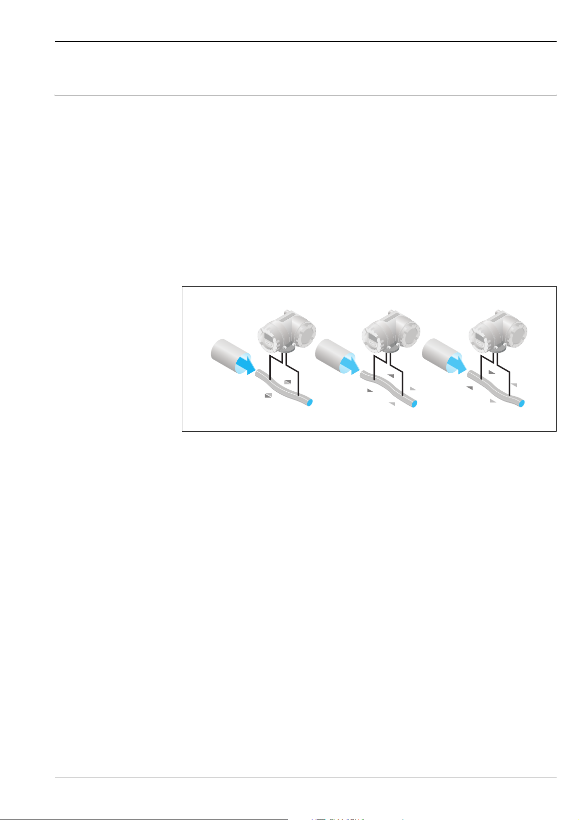
In the Promass F and M sensors, two parallel measuring tubes containing flowing fluid oscillate in antiphase,
acting like a tuning fork. The Coriolis forces produced at the measuring tubes cause a phase shift in the tube
oscillations (see illustration):
• At zero flow, in other words when the fluid is at a standstill, the two tubes oscillate in phase (1).
• Mass flow causes deceleration of the oscillation at the inlet of the tubes (2) and acceleration at the outlet (3).
A
B
A
B
A
B
12 3
a0003383
The phase difference (A-B) increases with increasing mass flow. Electrodynamic sensors register the tube
oscillations at the inlet and outlet.
System balance is ensured by the antiphase oscillation of the two measuring tubes. The measuring principle
operates independently of temperature, pressure, viscosity, conductivity and flow profile.
Density measurement
The measuring tubes are continuously excited at their resonance frequency. A change in the mass and thus the
density of the oscillating system (comprising measuring tubes and fluid) results in a corresponding, automatic
adjustment in the oscillation frequency. Resonance frequency is thus a function of fluid density. The microprocessor utilises this relationship to obtain a density signal.
Temperature measurement
The temperature of the measuring tubes is determined in order to calculate the compensation factor due to
temperature effects. This signal corresponds to the process temperature and is also available as an output.
The temperature measurement cannot be used to generate data for invoicing in applications subject to legal
metrology controls.
Endress+Hauser 3
Page 4
Proline Promass 84F, 84M
Esc
E
-
+
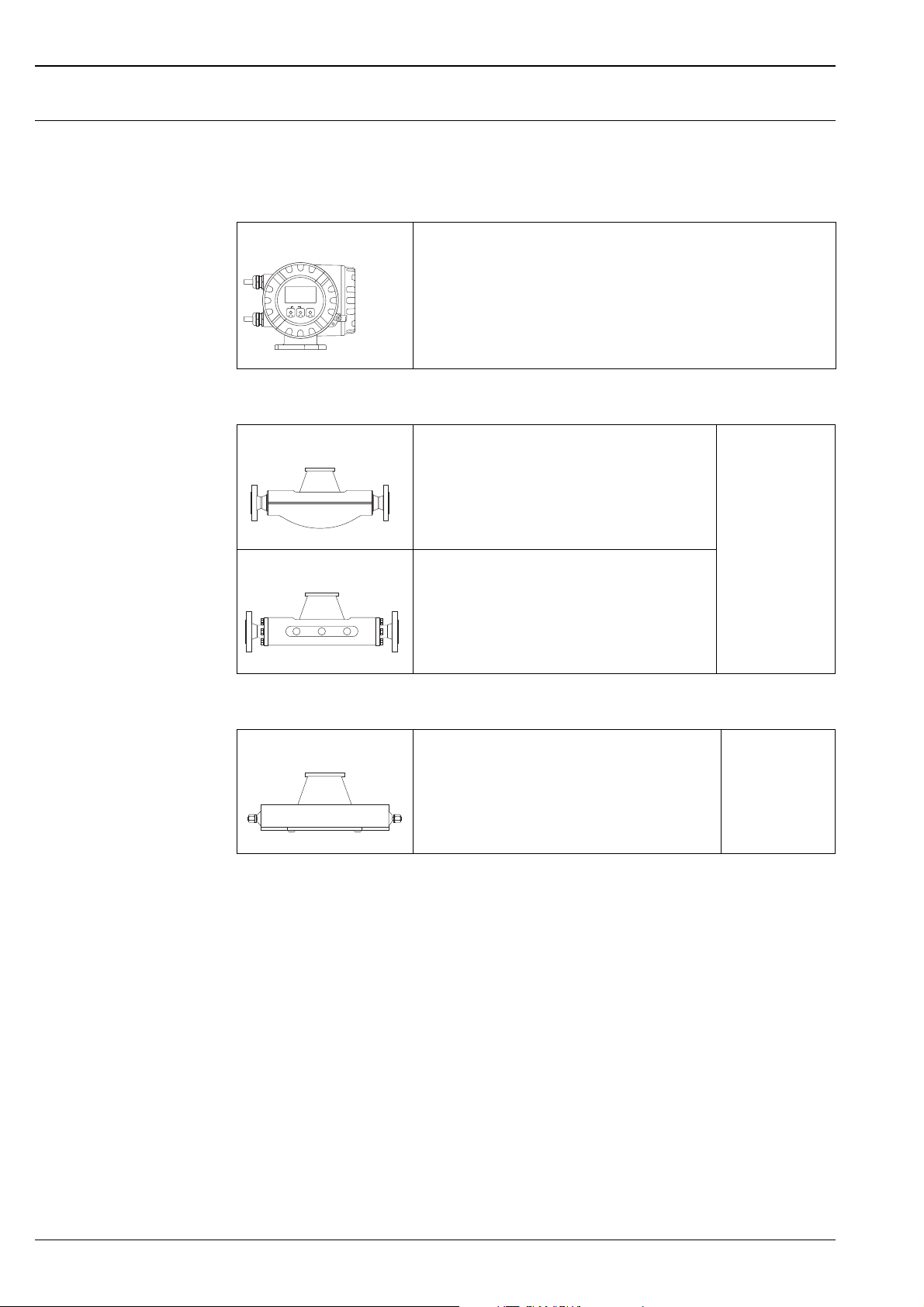
Measuring system The measuring system consists of a transmitter and a sensor. Two versions are available:
• Compact version: transmitter and sensor form a single mechanical unit.
• Remote version: transmitter and sensor are installed separately.
Transmitter
Promass 84
Sensor
F
M
• Four-line liquid-crystal display
• Operation with "Touch control"
• Application-specific Quick Setup
• Mass flow, volume flow, density and temperature measurement as well as
calculated variables (e.g. corrected volume flow)
a0003672
• Universal sensor for fluid temperatures up to 350 °C
• Nominal diameters DN 8 to 250
• Material: Stainless Steel EN 1.4539/ASTM 904L,
EN 1.4404/ASTM 316L, Alloy C-22 DIN 2.4602
a0003673
• Robust sensor for extreme process pressures, high
requirements for the secondary containment and fluid
temperatures up to 150 °C
• Nominal diameters DN 8 to 80
• Material: Titanium, Ti Grade 2, Ti Grade 9
a0003676
Documentation
No. TI 067D/06/en
Other sensors can be found in the separate documentation
A
• Single-tube system for highly accurate measurement of
very small flows
• Nominal diameters DN 2 to 4
• Material: Stainless Steel EN 1.4539/ASTM 904L,
EN 1.4404/ASTM 316L (process connection),
Alloy C-22 DIN 2.4602
a0003679
Documentation
No. TI 068D/06/en
4 Endress+Hauser
Page 5
Proline Promass 84F, 84M
Input
Measured variable • Mass flow (proportional to the phase difference between two sensors mounted on the measuring tube to
register a phase shift in the oscillation)
• Fluid density (proportional to resonance frequency of the measuring tube)
• Fluid temperature (measured with temperature sensors)
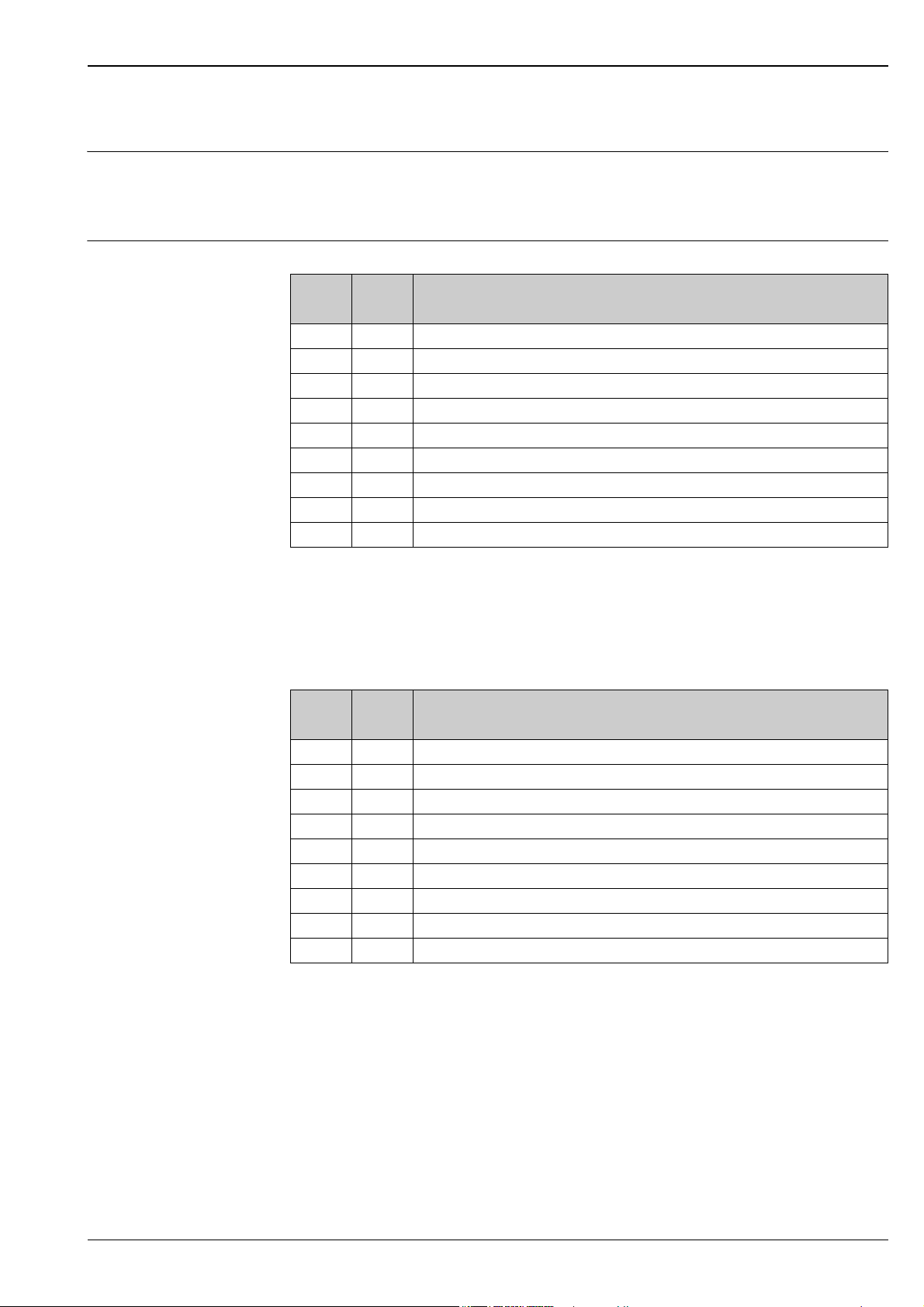
Measuring range in noncustody transfer mode
Measuring ranges for liquids
DN Promass Range for full scale values (liquids) g
[mm] [kg/h]
8 F, M 0 to 2000
15 F, M 0 to 6500
25 F, M 0 to 18000
40 F, M 0 to 45000
50 F, M 0 to 70000
80 F, M 0 to 180000
100 F 0 to 350000
150 F 0 to 800000
250 F 0 to 2200000
min(F)
to g
max(F)
Measuring ranges for gases
The full scale values depend on the density of the gas. Use the formula below to calculate the full scale values:
g
= g
max(G)
= Max. full scale value for gas [kg/h]
g
max(G)
g
= Max. full scale value for liquid [kg/h]
max(F)
DN Promass x
[mm] [kg/h]
8F, M 60
15 F, M 80
25 F, M 90
40 F, M 90
50 F, M 90
80 F, M 110
100 F 130
150 F 200
250 F 200
max(F)
· ρ
÷ x [kg/m³]
(G)
Here, g
can never be greater than g
max(G)
max(F)
Calculation example for gas:
• Sensor type: Promass F, DN 50
• Gas: air with a density of 60.3 kg/m³ (at 20 °C and 50 bar)
• Measuring range: 70000 kg/h
• x = 90 (for Promass F DN 50)
Max. possible full scale value:
g
max(G)
= g
max(F)
· ρ
÷ x [kg/m3] = 70000 kg/h · 60.3 kg/m³ ÷ 90 kg/m³ = 46900 kg/h
(G)
Recommended full scale values
See information in chapter "Limiting flow" → Page 22 ff.
Endress+Hauser 5
Page 6
Proline Promass 84F, 84M
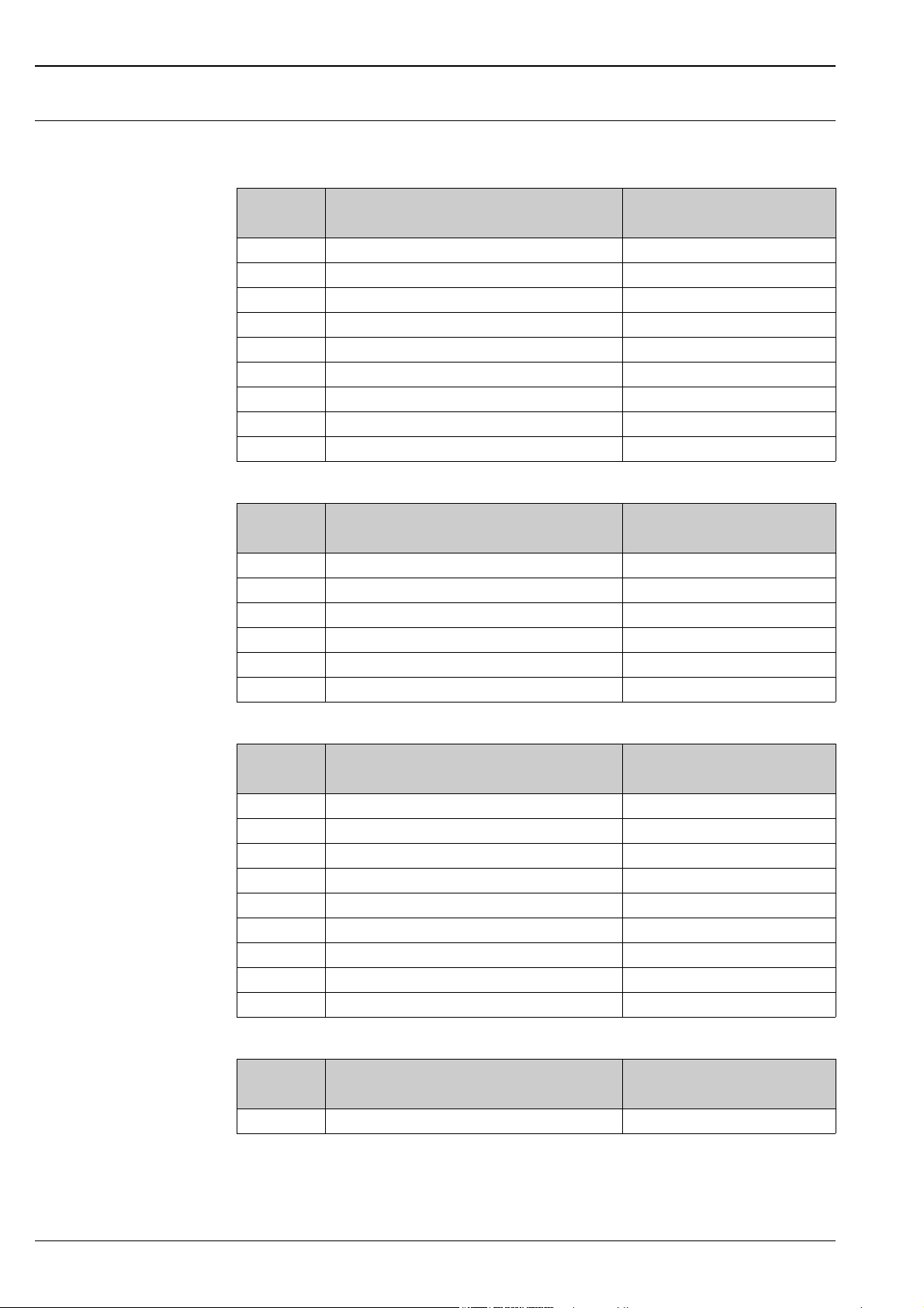
Measuring range in custody transfer mode
The following are example data for German PTB approval (liquids other than water).
Measuring ranges for liquids in mass flow for Promass F
DN Mass flow (liquids) Q
[mm] [kg/min] [kg]
8 1.5 to 30 0.5
15 5 to 100 2
25 15 to 300 5
40 35 to 700 20
50 50 to 1000 50
80 150 to 3000 100
100 200 to 4500 200
150 350 to 12000 500
250 1500 to 35000 1000
min
to Q
max
Smallest measured quantity
Measuring ranges for liquids in mass flow for Promass M
DN Mass flow (liquids) Q
[mm] [kg/min] [kg]
8 1.5 to 30 0.5
15 5 to 100 2
25 15 to 300 5
40 35 to 700 20
50 50 to 1000 50
80 150 to 3000 100
min
to Q
max
Smallest measured quantity
Measuring ranges for liquids in volume flow (also LPG) for Promass F
DN Volume flow (liquids) Q
[mm] [l/min] [l]
8 1.5 to 30 0.5
15 5 to 100 2.0
25 15 to 300 5.0
40 35 to 700 20
50 50 to 1000 50
80 150 to 3000 100
100 200 to 4500 200
150 350 to 12000 500
250 1500 to 35000 1000
min
to Q
max
Smallest measured quantity
Measuring ranges for liquids in volume flow (also LPG) for Promass M
DN Volume flow (liquids) Q
[mm] [l/min] [l]
80 150 to 3000 100
min
to Q
max
Smallest measured quantity
6 Endress+Hauser
Page 7
Proline Promass 84F, 84M
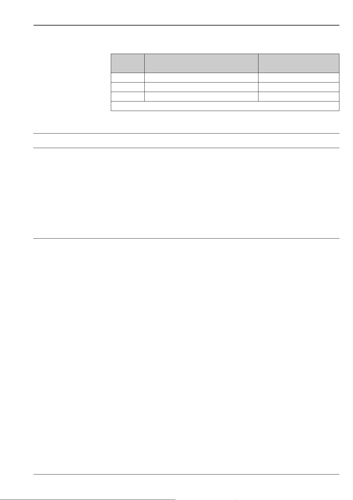
Measuring ranges for high pressure fuel gases CNG for Promass M
DN Mass flow (liquids) Q
[mm] [kg/min] [kg]
8 0.1 to 10 0.2
15 0.3 to 40 0.5
25 1.0 to 100 2.0
Max. Pressure = 250 bar resp. 350 bar for high pressure version
!
Note!
For information about the other approvals → see corresponding certificate.
Operable flow range Over 20 : 1 for verified device
Input signal Status input (auxiliary input), HART:
U = 3 to 30 V DC, R
= 5 kΩ, galvanically isolated.
i
Configurable for: totalizer reset, positive zero return, error message reset, zero point adjustment start.
Status input (auxiliary input), MODBUS RS485:
U = 3 to 30 V DC, R
= 3 kΩ, galvanically isolated, switch level: ±3 to ±30 V DC, independent of polarity.
i
Configurable for: totalizer reset, positive zero return, error message reset, zero point adjustment start.
Output
min
to Q
max
Smallest measured quantity
Output signal Current output:
Active/passive selectable, galvanically isolated, time constant selectable (0.05 to 100 s), full scale value
selectable, temperature coefficient: typically 0.005% o.r./°C, resolution: 0.5 μA
• Active: 0/4 to 20 mA, R
• Passive: 4 to 20 mA; supply voltage V
o.r. = of reading
Pulse / frequency output, HART:
For custody transfer measurement, two pulse outputs can be operated.
Passive, galvanically isolated, open collector, 30 V DC, 250 mA
• Frequency output:
Full scale frequency 2 to 10 000 Hz (f
In "Phase-shifted pulse outputs" operating mode, the end frequency is limited to a maximum
of 5000 Hz.
• Pulse output:
Pulse value and pulse polarity selectable, pulse width configurable (0.05 to 2000 ms)
Pulse / frequency output, MODBUS RS485:
Active/passive selectable, galvanically isolated
• Active: 24 V DC, 25 mA (max. 250 mA during 20 ms), R
• Passive: Open Collector, 30 V DC, 250 mA
• Frequency output:
Full scale frequency 2 to 10 000 Hz (f
• Pulse output:
Pulse value and pulse polarity selectable, pulse width configurable (0.05 to 2000 ms)
< 700 Ω (for HART: RL ≥ 250 Ω)
L
18 to 30 V DC; Ri ≥ 150 Ω
S
= 12500 Hz), on/off ratio 1:1, pulse width max. 2 s.
max
= 12500 Hz), on/off ratio 1:1, pulse width max. 2 s.
max
> 100 Ω
L
Endress+Hauser 7
Page 8
Proline Promass 84F, 84M
MODBUS RS485
• MODBUS device type: slave
• Address range: 1 to 247
• Functions codes supported: 03, 04, 06, 08, 16, 23
• Broadcast: supported with the function codes 06, 16, 23
• Physical interface: RS485 in accordance with standard EIA/TIA-485
• Baudrate supported: 1200, 2400, 4800, 9600, 19200, 38400, 57600, 115200 Baud
• Transmission mode: RTU oder ASCII
• Response time:
Direct data access = typically 25 to 50 ms
Auto-scan buffer (data area) = typically 3 to 5 ms
• Possible output combinations → Page 10
Relay output:
Normally closed (NC or break) or normally open (NO or make) contacts available
max. 30 V / 0.5 A AC; 60 V / 0.1 A DC,
galvanically isolated.
Signal on alarm • Current output: Failsafe mode selectable (e.g. in accordance with NAMUR Recommendation NE 43).
• Pulse/frequency output: Failsafe mode selectable.
• Relay output: De-energised by fault or power supply failure.
• MODBUS RS485: If an error occurs, the value NaN (not a number) is output for the process variables.
Load See "Output signal"
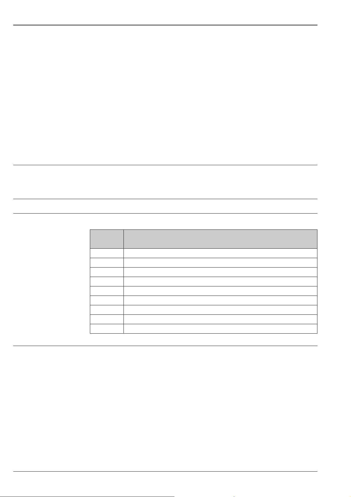
Low flow cutoff Switch points for low flow are selectable.
DN Low flow / factory settings (v ∼ 0.04 m/s)
[mm] [kg/h]
88.00
15 26.0
25 72.0
40 180
50 300
80 720
100 1200
150 2600
250 7200
Galvanic isolation All circuits for inputs, outputs, and power supply are galvanically isolated from each other.
8 Endress+Hauser
Page 9
Proline Promass 84F, 84M
Power supply
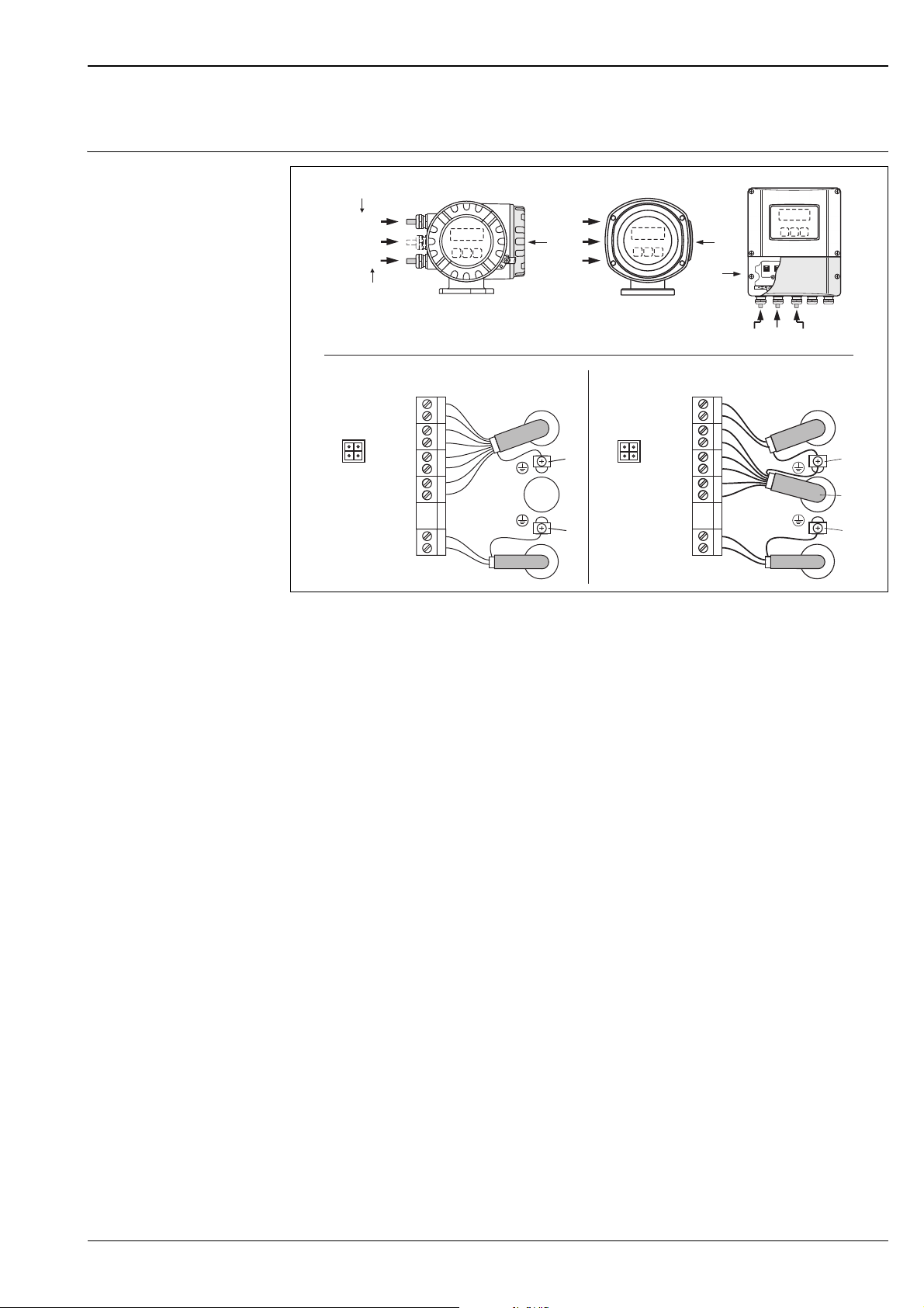
Electrical connection measuring unit
a/a
b/b
C
–/c
HART
b/c
–/b
a/a
MODBUS RS485
f
N (L-) 2
L1 (L+) 1
–27
+26
–25
+24
–23
+22
–21
+20
AB
b/c
–/b
a/a
HART
A (RxD/TxD-N)
B (RxD/TxD-P)
b
e
d
f
MODBUS RS485
27
26
25
–
+
24
23
–
+
22
21
–
+
20
N (L-)
2
L1 (L+)
1
a
Connecting the transmitter, cable cross-section: max. 2.5 mm²
A View A (aluminium field housing)
B View B (stainless steel field housing)
C View C (wall-mount housing)
a Cable for power supply: 85 to 260 V AC, 20 to 55 V AC, 16 to 62 V DC
– Terminal No. 1: L1 for AC, L+ for DC
– Terminal No2: N for AC, L- for DC
b Signal cable: Terminal assignment → Page 10
c Fieldbus cable: Terminal assignment → Page 10
d Ground terminal for protective earth
e Ground terminal for Signal cable/Fieldbus cable
f Service connector for connecting service interface FXA193 (Fieldcheck, ToF Tool - Fieldtool Package)
c
e
b
d
a
a0006816
Endress+Hauser 9
Page 10
Proline Promass 84F, 84M
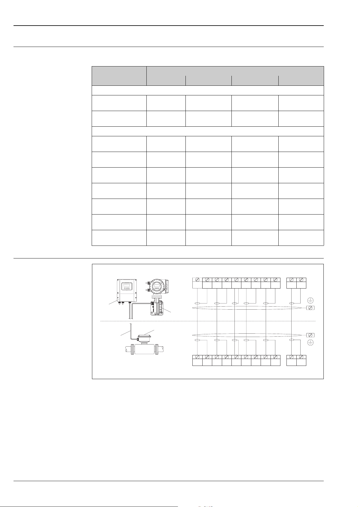
Terminal assignment Replacements for modules which are defective or which have to be replaced can be ordered as accessories.
Terminal No. (inputs/outputs)
Order variant 20 (+) / 21 (–) 22 (+) / 23 (–) 24 (+) / 25 (–) 26 (+) / 27 (–)
Fixed communication boards (permanent assignment)
84***-***********S – –
84***-***********T – –
Flexible communication boards
84***-***********D Status input Relay output
84***-***********M Status input
84***-***********N Current output
84***-***********Q – – Status input
84***-***********1 Relay output
84***-***********2 Relay output Current output 2
84***-***********7 Relay output 1 Relay output 2 Status input
Pulse/frequency
output 2
Pulse/frequency
output
Pulse/frequency
output 2
Pulse/freq. output
Ex i, passive
Pulse/freq. output
Ex i, passive
Pulse/frequency
output
Pulse/frequency
output 1
Status input
Pulse/frequency
output 1
Pulse/frequency
output
Current output
HART, Ex i, active
Current output
HART, Ex i, passive
Current output
HART
Current output
HART
MODBUS
RS485
MODBUS
RS485
Current output
HART
Current output 1
HART
MODBUS
RS485
Electrical connection remote version
a
b
S1 S1 S2 S2 GND TM TM TT TT
++ ++
4 5 6 7 8 9 10 11 12 41 42
d
d
d
e
c
Connection of remote version
a Wall-mount housing: non-hazardous area and ATEX II3G / Zone 2
b Wall-mount housing: ATEX II2G / Zone 1 /FM/CSA
c Flange version remote version
Terminal No.:
4/5 = gray
6/7 = green
8 = yellow
9/10 = pink
11/12 = white
41/42 = brown
4 5 6 7 8 9 10 11 12 41 42
++ ++
S1 S1 S2 S2 GND TM TM TT TT
a0003681
10 Endress+Hauser
Page 11
Proline Promass 84F, 84M
Supply voltage 85 to 260 V AC, 45 to 65 Hz
20 to 55 V AC, 45 to 65 Hz
16 to 62 V DC
Switching on the power supply in custody transfer mode
If the device is started in custody transfer mode, for example also after a power outage, system error No. 271
"POWER BRK. DOWN" flashes on the local display. The fault message can be acknowledged or reset using the
"Enter" key or by means of the status input configured accordingly.
Cable entries Power-supply and signal cables (inputs/outputs):
• Cable entry M20 × 1.5 (8 to 12 mm)
• Thread for cable entries, ½" NPT, G ½"
Connecting cable for remote version:
• Cable entry M20 × 1.5 (8 to 12 mm)
• Thread for cable entries, ½" NPT, G ½"
2
Remote version cable specifications
• 6 × 0.38 mm
• Conductor resistance: ≤ 50 Ω/km
PVC cable with common shield and individually shielded cores
• Capacitance: core/shield: ≤ 420 pF/m
• Cable length: max. 20 m
• Operating temperature: max. +105 °C
Operation in zones of severe electrical interference:
The measuring device complies with the general safety requirements in accordance with EN 61010-1,
the EMC requirements of ICE/EN 61326, and NAMUR recommendation NE 21/43.
Power consumption AC: <15 VA (including sensor)
DC: <15 W (including sensor)
Switch-on current
• Max. 13.5 A (< 50 ms) at 24 V DC
• Max. 3 A (< 5 ms) at 260 V AC
Power supply failure Lasting min. 1 power cycle:
• EEPROM or T-DAT save measuring system data if the power supply fails.
• S-DAT: exchangeable data storage chip with sensor specific data
(nominal diameter, serial number, calibration factor, zero point, etc.)
• See Note on Page 11 "Switching on the power supply in custody transfer mode"
Potential equalisation No special measures for potential equalization are required. For instruments for use in hazardous areas, observe
the corresponding guidelines in the specific Ex documentation.
Endress+Hauser 11
Page 12
!
Proline Promass 84F, 84M
Performance characteristics
Note!
The accuracy solely refers to the measuring device suitable for custody transfer measurement and not to the
measuring system.
Reference operating conditions
Maximum measured error The following values refer to the pulse/frequency output. Deviation at the current output is typically ±5 μA.
Error limits following ISO/DIS 11631:
• 20 to 30 °C; 2 to 4 bar
• Accuracy based on accredited calibration rigs according to ISO 17025
• Zero point calibrated under operating conditions
• Field density calibrated (or special density calibration)
Mass flow (liquid):
• ±0.10% ± [(zero point stability ÷ measured value) · 100]% o.r.
• ±0.05% ± [(zero point stability ÷ measured value) · 100]% o.r., PremiumCal (optional)
Mass flow (gas):
• Promass F: ±0.35% ± [(zero point stability ÷ measured value) · 100]% o.r.
• Promass M: ±0.50% ± [(zero point stability ÷ measured value) · 100]% o.r.
Volume flow (liquid)
• Promass F: ±0.15% ± [(zero point stability ÷ measured value) · 100]% o.r.
• Promass M: ±0.25% ± [(zero point stability ÷ measured value) · 100]% o.r.
o.r. = of reading
Zero point stability
DN Max. full scale value Zero point stability
Promass F Promass F
(High Temperature)
[mm] [kg/h] [kg/h] [kg/h] [kg/h]
820000.03− 0.10
15 6500 0.20 − 0.325
25 18000 0.54 1.80 0.90
40 45000 2.25 − 2.25
50 70000 3.50 7.00 3.50
80 180 000 9.00 18.0 9.00
100 350 000 14.0 −−
150 800 000 32.0 −−
250 2 200 000 88.0 −−
Promass M
12 Endress+Hauser
Page 13
Proline Promass 84F, 84M
Sample calculation
[%]
±1.0
±0.5
±0.2
0
024681012141618
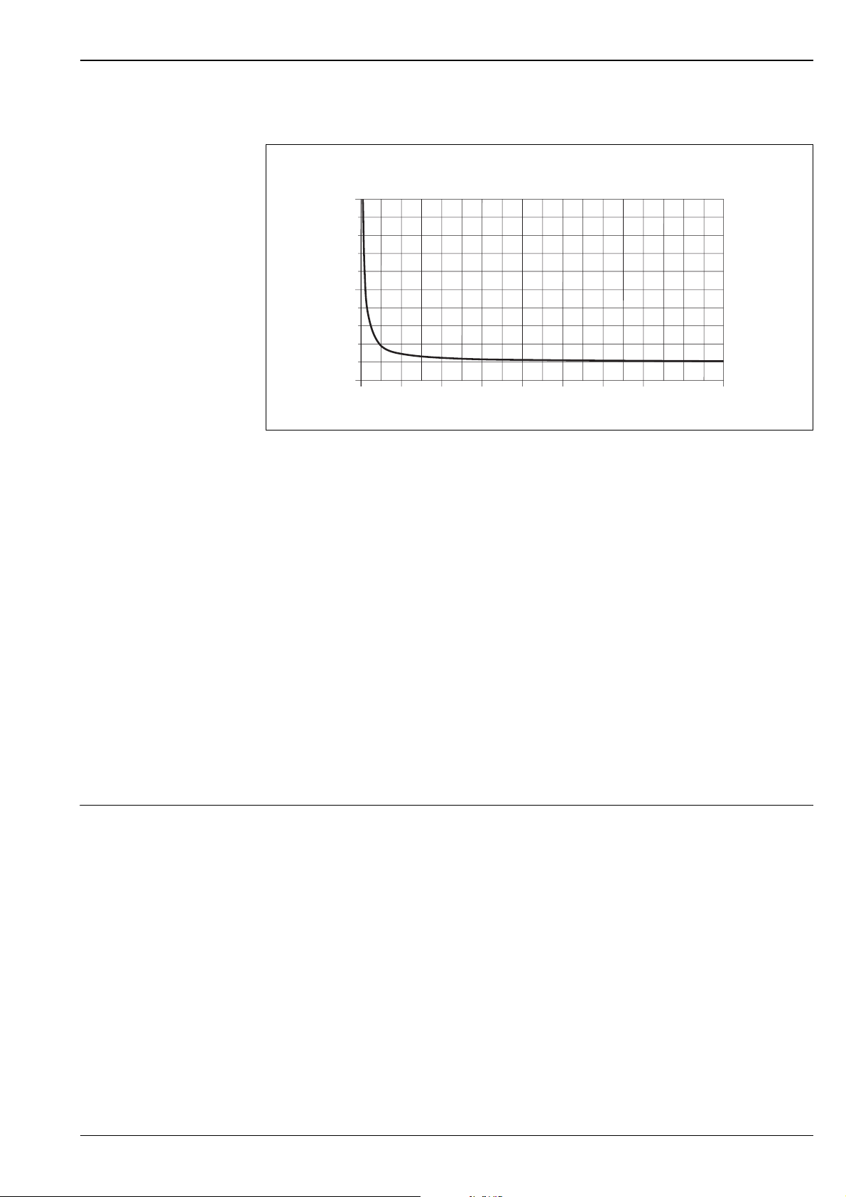
Maximum measured error in % of reading (example: Promass 84F / DN 25)
t/h
a0004604
Calculation example (mass flow, liquid):
Given: Promass 84F / DN 25, measured value flow = 8000 kg/h
Max. measured error: ±0.10% ± [(zero point stability ÷ measured value) · 100]% o.r.
Maximum measured error → ±0.10% ± 0.54 kg/h ÷ 8000 kg/h · 100% = ±0.107%
Density (liquid)
• Standard calibration (1g/cc = 1 kg/l)
– Promass F: ±0.01 g/cc
– Promass M: ±0.02 g/cc
• Special density calibration (optional), not for high temperature version
– Promass F: ±0.001 g/cc
– Promass M: ±0.002 g/cc
• After field density calibration or under reference conditions
– Promass F: ±0.0005 g/cc
– Promass M: ±0.0010 g/cc
Temperature
±0.5 °C ±0.005 · T (T = fluid temperature in °C)
Repeatability Mass flow (liquid):
±0.05% ± [½ · (zero point stability ÷ measured value) · 100]% o.r.
Mass flow (gas):
±0.25% ± [½ · (zero point stability ÷ measured value) · 100]% o.r.
Volume flow (liquid):
• Promass F: ±0.05% ± [½ · (zero point stability ÷ measured value) · 100]% o.r.
• Promass M: ±0.10% ± [½ · (zero point stability ÷ measured value) · 100]% o.r.
o.r. = of reading
Zero point stability: see "Max. measured error"
Calculation example (mass flow, liquid):
Given: Promass 84F / DN 25, measured value flow = 8000 kg/h
Repeatability: ±0.05% ± [(½ · (zero point stability ÷ measured value) · 100]% o.r.
Repeatability: ±0.05% ± ½ · 0.54 kg/h ÷ 8000 kg/h · 100% = ±0.053%
Endress+Hauser 13
Page 14
Density measurement (liquid)
1 g/cc = 1 kg/l
• Promass F: ±0.00025 g/cc
• Promass M: ±0.0005 g/cc
Temperature measurement
±0.25 °C ±0.0025 · T; (T = fluid temperature in °C)
Proline Promass 84F, 84M
Influence of medium temperature
When there is a difference between the temperature for zero point adjustment and the process temperature,
the typical measured error of the Promass sensor is ±0.0002% of the full scale value / °C.
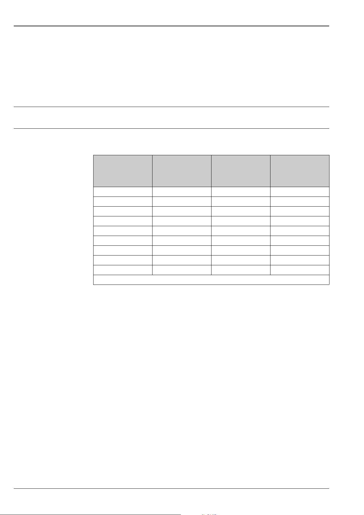
Influence of medium pressure The table below shows the effect on accuracy of mass flow due to a difference between calibration pressure
and process pressure.
DN Promass F,
[mm] [% o.r./bar] [% o.r./bar] [% o.r./bar]
8 No influence 0.009 0.006
15 No influence 0.008 0.005
25 No influence 0.009 0.003
40 −0.003 0.005 −
50 −0.008 No influence −
80 −0.009 No influence −
100 −0.012 −−
150 −0.009 −−
250 −0.009 −−
o.r. = of reading
Promass F High
temperature
Promass M Promass M High pressure
14 Endress+Hauser
Page 15
Proline Promass 84F, 84M
Operating conditions: Installation
Installation instructions Note the following points:
• No special measures such as supports are necessary. External forces are absorbed by the construction of the
instrument, for example the secondary containment.
• The high oscillation frequency of the measuring tubes ensures that the correct operation of the measuring
system is not influenced by pipe vibrations.
• No special precautions need to be taken for fittings which create turbulence (valves, elbows, T-pieces, etc.),
as long as no cavitation occurs.
• For mechanical reasons and in order to protect the pipe, it is advisable to support heavy sensors.
• Please refer to the verification ordinances for the installation conditions of the approval for custody transfer
in question.
!
Note!
The necessary steps for creating a measuring system and obtaining approval from the Standards Authorities
must be clarified with the authority for legal metrology controls responsible.
Mounting location
Entrained air or gas bubbles in the measuring tube can result in an increase in measuring errors.
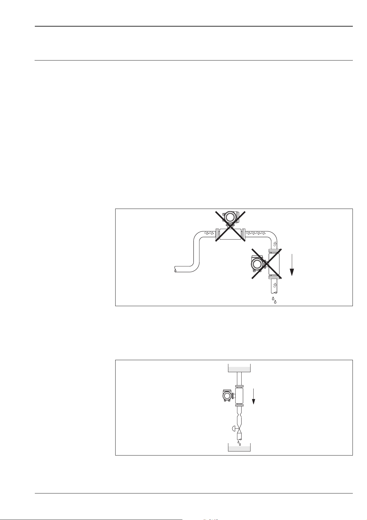
Avoid the following mounting locations in the pipe:
• Highest point of a pipeline. Risk of air accumulating.
• Directly upstream from a free pipe outlet in a vertical pipeline
a0003605
Mounting location
Notwithstanding the above, the installation proposal below permits installation in an open vertical pipeline.
Pipe restrictions or the use of an orifice with a smaller cross-section than the nominal diameter prevent the
sensor running empty while measurement is in progress.
1
2
3
4
5
a0003597
Installation in a down pipe (e.g. for batching applications)
1 = Supply tank, 2 = Sensor, 3 = Orifice plate, pipe restriction (see Table), 4 = Valve, 5 = Batching tank
Endress+Hauser 15
Page 16
Proline Promass 84F, 84M
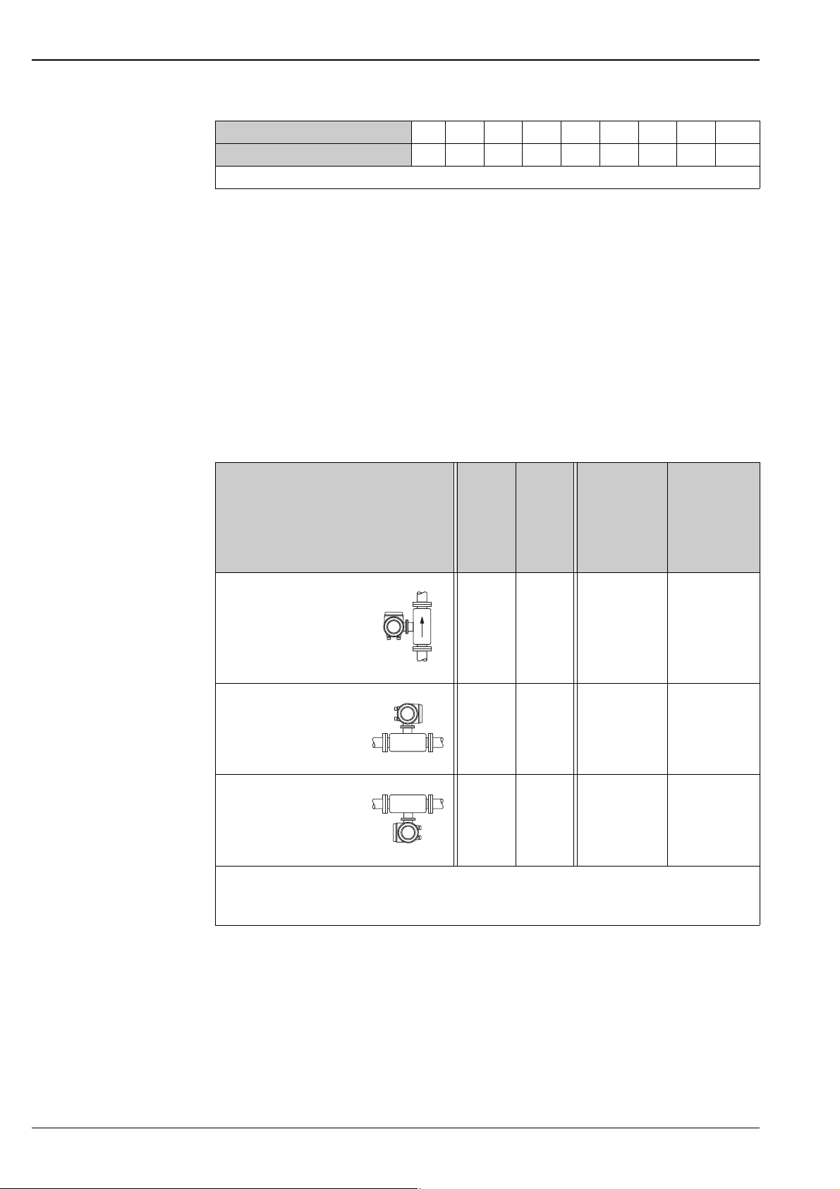
DN 815254050801001)1501)250
∅ Orifice plate, pipe restriction [mm] 6 10 14 22 28 50 65 90 150
1) only Promass F
1)
Orientation
Make sure that the direction of the arrow on the nameplate of the sensor matches the direction of flow
(direction in which the fluid flows through the pipe).
Vertical
Recommended orientation with upward direction of flow (View V). When fluid is not flowing, entrained solids
will sink down and gases will rise away from the measuring tube. The measuring tubes can be completely
drained and protected against solids build-up.
Horizontal
The measuring tubes must be horizontal and beside each other. When installation is correct the transmitter
housing is above or below the pipe (View H1/H2). Always avoid having the transmitter housing in the same
horizontal plane as the pipe.
Promass F, M
Standard,
compact
Promass F, M
Standard,
Fig. V
Vertical orientation
a0004572
Fig. H1
Horizontal orientation
Transmitter head up
a0004576
Fig. H2
Horizontal orientation
Transmitter head down
a0004580
ÃÃ = Recommended orientation
à = Orientation recommended in certain situations
✘ = Impermissible orientation
remote
ÃÃ ÃÃ ÃÃ ÃÃ
ÃÃ ÃÃ
ÃÃ
n
ÃÃ
n
Promass F
High-temperature,
compact
✘
TM = >200 °C
m
ÃÃ
n
Promass F
High-temperature,
remote
Ã
TM = >200 °C
m
ÃÃ
n
In order to ensure that the maximum permissible ambient temperature for the transmitter
(–20 °C to +60 °C, optional –40 °C to +60 °C) is not exceeded, we recommend the following orientations:
m = For fluids with very high temperatures (>200 C), we recommend the horizontal orientation with the
transmitter head pointing downwards (Fig. H2) or the vertical orientation (Fig. V).
n = For fluids with low temperatures, we recommend the horizontal orientation with the transmitter head
pointing upwards (Fig. H1) or the vertical orientation (Fig. V).
16 Endress+Hauser
Page 17
Proline Promass 84F, 84M
Special installation instructions for Promass F
Caution!
"
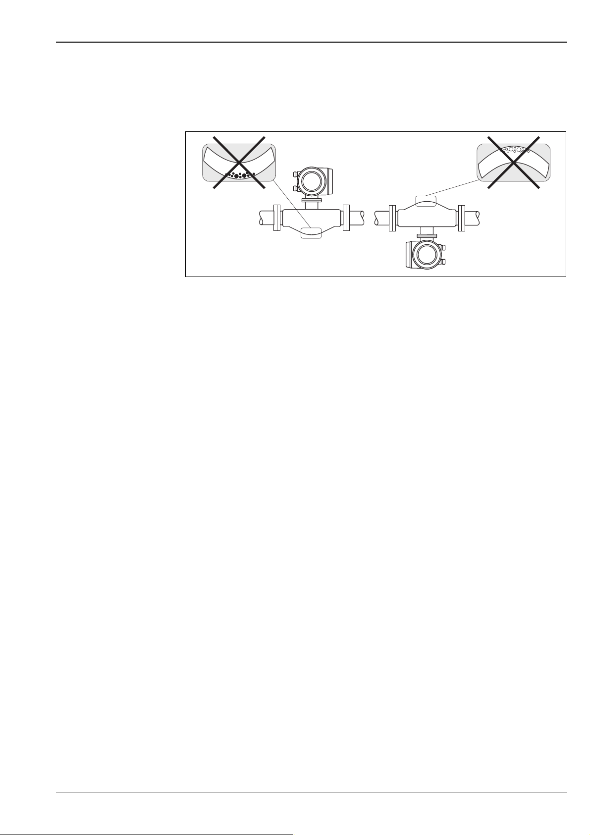
The two measuring tubes for Promass F are slightly curved. The position of the sensor, therefore, has to be
matched to the fluid properties when the sensor is installed horizontally .
1
Promass F, installed horizontally
1 Not suitable for fluids with entrained solids. Risk of solids accumulating.
2 Not suitable for outgassing fluids. Risk of air accumulating.
Heating
Some fluids require suitable measures to avoid loss of heat at the sensor. Heating can be electric, e.g. with
heated elements, or by means of hot water or steam pipes made of copper or heating jackets.
Caution!
"
• Risk of electronics overheating! Make sure that the maximum permissible ambient temperature for the
transmitter is not exceeded. Consequently, make sure that the adapter between sensor and transmitter and
the connection housing of the remote version always remain free of insulating material. Note that a certain
orientation might be required, depending on the fluid temperature.
• With a fluid temperature between 200 °C to 350 °C the remote version of the high-temperature version is
preferable.
• When using electrical heat tracing whose heat is regulated using phase control or by pulse packs, it cannot
be ruled out that the measured values are influenced by magnetic fields which may occur, (i.e. at values
greater than those permitted by the EC standard (Sinus 30 A/m)). In such cases, the sensor must be
magnetically shielded (except for Promass M).
The secondary containment can be shielded with tin plates or electric sheets without privileged direction
(e.g. V330-35A) with the following properties:
– Relative magnetic permeability μ
– Plate thickness d ≥ 0.35 mm
• Information on permissible temperature ranges → Page 21
Special heating jackets which can be ordered as accessories from Endress+Hauser are available for the sensors.
≥ 300
r
2
a0004581
Endress+Hauser 17
Page 18
Proline Promass 84F, 84M
1
2
Thermal insulation
Some fluids require suitable measures to avoid loss of heat at the sensor. A wide range of materials can be used
to provide the required thermal insulation.
max. 60
E
s
c
-
+
E
max. 60
a0004614-en
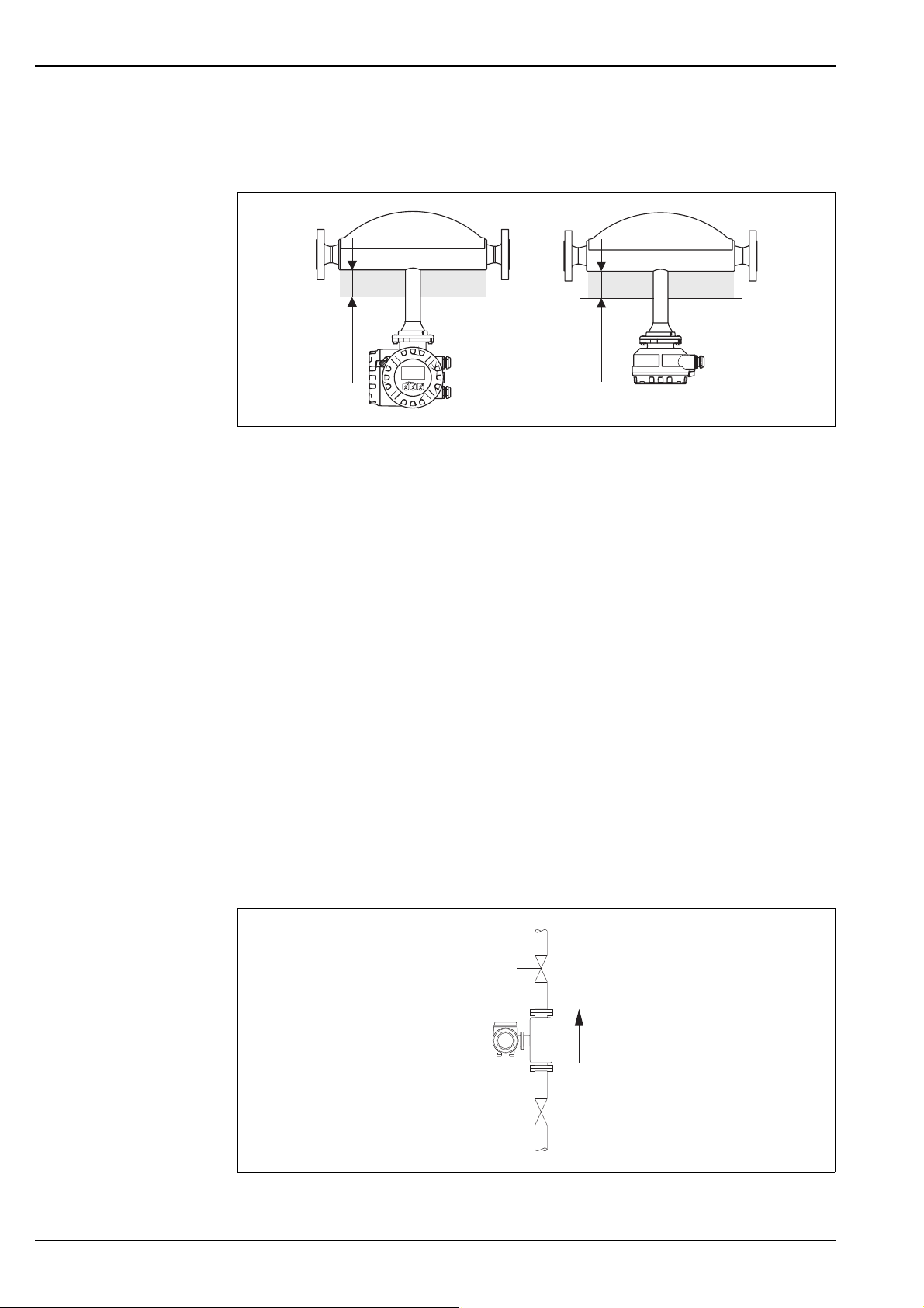
In the case of the Promass F high-temperature version, a maximum insulation thickness of 60 mm must be observed in the
area of the electronics/neck.
If the Promass F high-temperature version is installed horizontally (with transmitter head pointing upwards),
an insulation thickness of min. 10 mm is recommended to reduce convection. The maximum insulation
thickness of 60 mm must be observed.
Zero point adjustment
All Promass measuring devices are calibrated with state-of-the-art technology. The zero point determined in
this way is imprinted on the nameplate. Calibration takes place under reference operating conditions.
→ Page 12 ff.
Consequently, the zero point adjustment is generally not necessary for Promass!
Experience shows that the zero point adjustment is advisable only in special cases:
• To achieve highest measuring accuracy also with very small flow rates.
• Under extreme process or operating conditions (e.g. very high process temperatures or very high viscosity
fluids).
Note the following before you perform a zero point adjustment:
• A zero point adjustment can be performed only with fluids that contain no gas or solid contents.
• Zero point adjustment is performed with the measuring tubes completely filled and at zero flow
(v = 0 m/s). This can be achieved, for example, with shut-off valves upstream and/or downstream of the
sensor or by using existing valves and gates.
– Normal operation → valves 1 and 2 open
– Zero point adjustment with pump pressure → Valve 1 open / valve 2 closed
– Zero point adjustment without pump pressure → Valve 1 closed / valve 2 open
Zero point adjustment and shut-off valves
18 Endress+Hauser
a0003601
Page 19

Proline Promass 84F, 84M
Inlet and outlet runs There are no installation requirements regarding inlet and outlet runs.
Length of connecting cable remote version
System pressure It is important to ensure that cavitation does not occur, because it would influence the oscillation of the
max. 20 m
measuring tube. No special measures need to be taken for fluids which have properties similar to water under
normal conditions.
In the case of liquids with a low boiling point (hydrocarbons, solvents, liquefied gases) or in suction lines, it is
important to ensure that pressure does not drop below the vapour pressure and that the liquid does not start
to boil. It is also important to ensure that the gases that occur naturally in many liquids do not outgas. Such
effects can be prevented when system pressure is sufficiently high.
Consequently, it is generally best to install the sensor:
• downstream from pumps (no danger of vacuum),
• at the lowest point in a vertical pipe.
Endress+Hauser 19
Page 20
Operating conditions: Environment
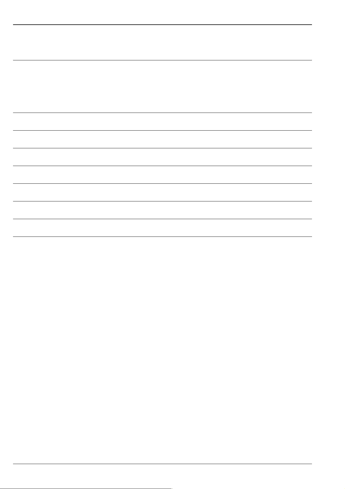
Ambient temperature range Sensor and transmitter
Standard: –20 to +60 °C
Optional: –40 to +60 °C
!
Storage temperature –40 to +80 °C, preferably +20 °C
Ambient class B, C, I
Degree of protection Standard: IP 67 (NEMA 4X) for transmitter and sensor
Shock resistance According to IEC 68-2-31
Note!
• Install the device at a shady location. Avoid direct sunlight, particularly in warm climatic regions.
• At ambient temperatures below –20 °C the readability of the display may be impaired.
Proline Promass 84F, 84M
Vibration resistance Acceleration up to 1 g, 10 to 150 Hz, following IEC 68-2-6
CIP cleaning yes
SIP cleaning yes
Electromagnetic compatibility (EMC)
To ICE/EN 61326 and NAMUR recommendation NE 21
20 Endress+Hauser
Page 21

Proline Promass 84F, 84M
Operating conditions: Process
Medium temperature range Sensor
• Promass F: –50 to +200 °C
• Promass F (High temperature version): –50 to +350 °C
• Promass M: –50 to +150 °C
Seals
•Promass F:
No internal seals
•Promass M:
– Viton: –15 to 200 °C
– EPDM: –40 to +160 °C
– Silikon: –60 to +200 °C
– Kalrez: –20 to +275 °C
– FEP sheathed (not for gas applications): –60 to +200 °C
Medium pressure range (nominal pressure)
!
#
Flanges
Promass F:
According to DIN PN 16 to 100 / according to ASME B16.5 Cl 150, Cl 300, Cl 600 / JIS 10K, 20K, 40K, 63K
Promass M:
According to DIN PN 40 to 100 / according to ASME B16.5 Cl 150, Cl 300, Cl 600 / JIS 10K, 20K, 40K, 63K
Promass M (high pressure version)
Measuring tubes, connector, couplings: max. 350 bar
Note!
Material load diagrams for the process connections can be found on → Page 58 ff.
Pressure ranges of secondary containment
•Promass F
– DN 8 to 50: 40 bar
– DN 80: 25 bar
– DN 100 to 150: 16 bar
– DN 250: 10 bar
•Promass M
– 100 bar
Warning!
In case a danger of measuring tube failure exists due to process characteristics, e.g. with corrosive process
fluids, we recommend the use of sensors whose secondary containment is equipped with special pressure
monitoring connections or rupture disks (ordering option). With the help of these connections, fluid collected
in the secondary containment in the event of tube failure can be bled off. This is especially important in high
pressure gas applications. These connections can also be used for gas circulation and/or detection.
Dimensions → Page 53
Rupture disk (optional, only Promass F)
Further informationen → Page 54.
Endress+Hauser 21
Page 22
Limiting flow See "Measuring range" section. → Page 68 ff.
Select nominal diameter by optimising between required flow range and permissible pressure loss. An overview
of max. possible full scale values can be found in the "Measuring range" Section.
• The minimum recommended full scale value is approx. 1/20 of the max. full scale value.
• In most applications, 20 to 50% of the maximum full scale value can be considered ideal.
• Select a lower full scale value for abrasive substances such as fluids with entrained solids
(flow velocity <1 m/s).
• For gas measurement the following rules apply:
– Flow velocity in the measuring tubes should not be more than half the sonic velocity (0.5 Mach).
– The maximum mass flow depends on the density of the gas: formula → Page 5 ff.
Pressure loss in metric units Pressure loss depends on the properties of the fluid and on its flow.
The following formulas can be used to approximately calculate the pressure loss:
2·
Reynolds number
Re =
g
pnr·d· ·
Proline Promass 84F, 84M
a0004623
Re ≥ 2300
1)
Re < 2300
Δp = pressure loss [mbar]
ν = kinematic viscosity [m2/s]
g = mass flow [kg/s]
Drp=K· · ·
Dp=K1· · +gn
ρ = fluid density [kg/m3]
d = inside diameter of measuring tubes [m]
K to K2 = constants (depending on nominal diameter)
0.25 1.85 –0.86
gn
K2 · ·
0.25 2
r
gn
1) To compute the pressure loss for gases, always use the formula for Re ≥ 2300.
Pressure loss coefficient for Promass F
DN d[m] K K1 K2
8 5.35 · 10
15 8.30 · 10
25 12.00 · 10
40 17.60 · 10
50 26.00 · 10
80 40.50 · 10
100 51.20 · 10
150 68.90 · 10
250 102.26 · 10
–3
–3
–3
–3
–3
–3
–3
–3
–3
5.70 · 10
5.80 · 10
1.90 · 10
3.50 · 10
7.00 · 10
1.10 · 10
3.54 · 10
1.36 · 10
3.00 · 10
7
6
6
5
4
4
3
3
2
9.60 · 10
1.90 · 10
6.40 · 10
1.30 · 10
5.00 · 10
7.71 · 10
3.54 · 10
2.04 · 10
6.10 · 10
7
7
6
6
5
4
4
4
3
1.90 · 10
10.60 · 10
4.50 · 10
1.30 · 10
1.40 · 10
1.42 · 10
5.40 · 10
6.46 · 10
1.33 · 10
a0004626
a0004628
7
5
5
5
4
4
3
2
2
22 Endress+Hauser
Page 23
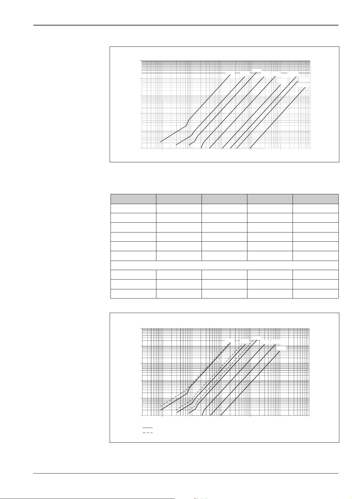
Proline Promass 84F, 84M
[mbar]
10000
1000
100
DN 15
DN 25
DN 40
DN 50
DN 80
DN 100
DN 150
DN 250
DN 8
10
1
0.1
0.001
0.01
0.1
1
10
100 1000
Pressure loss diagram for water
Pressure loss coefficient for Promass M
DN d[m] K K1 K2
8 5.53 · 10
15 8.55 · 10
25 11.38 · 10
40 17.07 · 10
50 25.60 · 10
80 38.46 · 10
High pressure version
8 4.93 · 10
15 7.75 · 10
25 10.20 · 10
–3
–3
–3
–3
–3
–3
–3
–3
–3
5.2 · 10
5.3 · 10
1.7 · 10
3.2 · 10
6.4 · 10
1.4 · 10
6.0 · 10
8.0 · 10
2.7 · 10
7
6
6
5
4
4
7
6
6
8.6 · 10
1.7 · 10
5.8 · 10
1.2 · 10
4.5 · 10
8.2 · 10
1.4 · 10
2.5 · 10
8.9 · 10
7
7
6
6
5
4
8
7
6
1.7 · 10
9.7 · 10
4.1 · 10
1.2 · 10
1.3 · 10
3.7 · 10
2.8 · 10
1.4 · 10
6.3 · 10
[t/h]
a0001396
7
5
5
5
4
4
7
6
5
[mbar]
10000
1000
100
0.1
10
1
0.001
DN 8
0.01
1
2
0.1
1
DN 15
10
DN 25
DN 40
DN 50
DN 80
100 1000
[t/h]
a0004605
Pressure loss diagram for water
1 Promass M
2 Promass M (high pressure version)
Endress+Hauser 23
Page 24

Proline Promass 84F, 84M
Pressure loss in US units Pressure loss ist dependent on fluid properties nominal diameter. Consult Endress+Hauser for Applicator PC
software to determine pressure loss in US units. All important instrument data is contained in the Applicator
software programm in order to optimize the design of measuring system. The software is used for following
calculations:
• Nominal diameter of the sensor with fluid characteristics such as viscosity, density, etc.
• Pressure loss downstream ot the measuring point.
• Converting mass flow to volume flow, etc.
• Simultaneous display of various meter size.
• Determining measuring ranges.
The Applicator runs on any IBM compatible PC with windows.
24 Endress+Hauser
Page 25

Proline Promass 84F, 84M
Custody transfer measurement
Promass 84 is a flowmeter suitable for custody transfer measurement for liquids (other than water) and gases.
Custody transfer variables •Mass
• Volume
•Density
Suitability for custody transfer, metrological control, obligation to subsequent verification
"
!
Verification (Example)
!
Promass 84 flowmeters are usually verified on site using reference measurements. Only once it has been
verified on site by the Verification Authority for legal metrology controls may the measuring device be regarded
as verified and used for applications subject to legal metrology controls. The associated seal (stamp) on the
measuring device ensures this status.
Caution!
Only flowmeters verified by the Verification Authorities may be used for invoicing in applications subject to
legal metrology controls. For all verification processes, both the corresponding approvals and the countryspecific requirements resp. regulations (e.g. such as the German Verification Act) must be observed. The owner
/ user of the instrument is obliged to subsequent verification.
Approval for custody transfer
The requirements of the following legal metrology authorities are taken into consideration:
• PTB, Germany; (www.eichamt.de)
• NMi, The Netherlands; (www.nmi.nl)
• METAS, Switzerland; (www.metas.ch)
• BEV, Austria; (www.bev.gv.at)
Switching on the power supply in custody transfer mode
If the device is started in custody transfer mode, for example also after a power outage, system error No. 271
"POWER BRK. DOWN" flashes on the local display. The fault message can be acknowledged or reset using the
"Enter" key or by means of the status input configured accordingly.
Note!
For correct measuring operation, it is not mandatory to reset the fault message.
Type-approved measuring systems for liquids other than water are always verified at their place of deployment.
For this purpose, the facility's owner-operator must make everything available when the Verification
Authorities come to inspect and verify the system. This includes:
• Scales or container with a reading unit with a load or volumetric capacity that corresponds to the operation
of the system at Q
0.1 % of the minimum measured quantity.
• Unit for removing the medium being measured after the totalizer to fill the scales or the container.
• Making a sufficient quantity of the medium being measured available. The quantity is derived from the
operation of the system. The following rule of thumb applies - quantity at:
3 × 1 minute at Q
plus 3 × 1 minute at ½ Q
plus 3 × 1 minute at Q
plus adequate quantity in reserve.
• Approval certificates
Note!
All issues should be clarified in advance with the authority responsible to ensure the successful verification of
the measuring system.
for one minute. The resolution of the scales display or the reading unit must be at least
max
,
min
,
max
,
max
Setting up custody transfer mode
A detailed description of the "setting up custody transfer mode" process is provided in the Operating
Instructions supplied with the device.
Endress+Hauser 25
Page 26
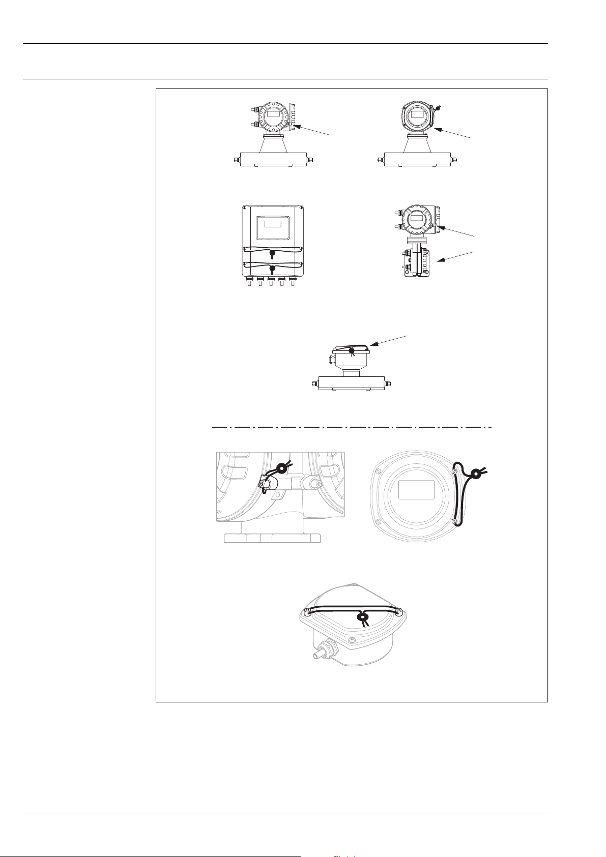
Stamp points
Proline Promass 84F, 84M
A
B
e
r
t
S
n
p
u
a
t
n
h
n
c
u
i
n
N
g
e
n
f
f
n
ö
e
l
i
h
w
e
K
t
v
i
e
l
c
h
e
a
i
g
r
i
c
p
t
e
r
u
r
c
i
e
a
t
o
s
v
s
v
t
o
a
i
e
c
r
u
e
r
c
t
p
r
i
i
a
g
e
c
l
i
h
e
v
t
e
K
w
h
i
l
e
l
i
n
s
e
o
o
i
r
s
u
n
s
t
e
N
a
e
p
p
p
a
a
’
l
s
r
i
o
r
v
u
A
C
AB
C
a0003467
Examples of how to seal the various device versions.
Disabling custody transfer mode
A detailed description of the "disabling custody transfer mode" process is provided in the Operating Instructions
supplied with the device.
26 Endress+Hauser
Page 27
Proline Promass 84F, 84M
Mechanical construction
Design/dimensions
in metric units
Dimensions:
Transmitter compact version, powder coated die-cast aluminium field housing → Page 28
Transmitter compact version, powder coated die-cast aluminium field housing → Page 28
Transmitter compact version, stainless steel field housing → Page 29
Transmitter and remote field housing (II2G/zone 1) → Page 29
Transmitter wall-mount housing (non hazardous area and II3G/zone 2) → Page 30
Connetion housing remote version → Page 31
Connetion housing remote version for heating → Page 31
Process connections Promass F → Page 32 ff.
Promass F: Flange connections EN (DIN) → Page 32
Promass F: Flange connections ASME B16.5 → Page 34
Promass F: Flange connections JIS → Page 36
Promass F: Tri-Clamp → Page 39
Promass F: DIN 11851 connections (threaded hygienic connection) → Page 40
Promass F: DIN 11864-1 Form A (threaded hygienic connection) → Page 40
Promass F: DIN 11864-2 Form A (flat flange with groove) → Page 41
Promass F: ISO 2853 (threaded hygienic connection) → Page 41
Promass F: SMS 1145 (threaded hygienic connection) → Page 42
Process connections Promass M → Page 42 ff.
Promass M: Flange connections EN (DIN) → Page 42
Promass M: Flange connections ASME B16.5 → Page 44
Promass M: Flange connections JIS → Page 45
Promass M: Tri-Clamp → Page 47
Promass M: DIN 11851 (threaded hygienic connection) → Page 48
Promass M: DIN 11864-1 Form A (threaded hygienic connection) → Page 48
Promass M: DIN 11864-2 Form A (flat flange with groove) → Page 49
Promass M: ISO 2853 (threaded hygienic connection) → Page 49
Promass M: SMS 1145 (threaded hygienic connection) → Page 50
Process connections Promass M (high pressure) → Page 50 ff.
Promass M (high pressure): ½"-NPT, 3/8"-NPT and G 3/8" → Page 50
Promass M (high pressure): ½"-SWAGELOK → Page 51
Promass M (high pressure): Connector with internal thread 7/8-14UNF → Page 51
Promass M: without process connections → Page 52
Purge connections / secondary containment monitoring → Page 53
Rupture disk
→ Page 54
Endress+Hauser 27
Page 28
Proline Promass 84F, 84M
Esc
E
-
+
Esc
E
-
+
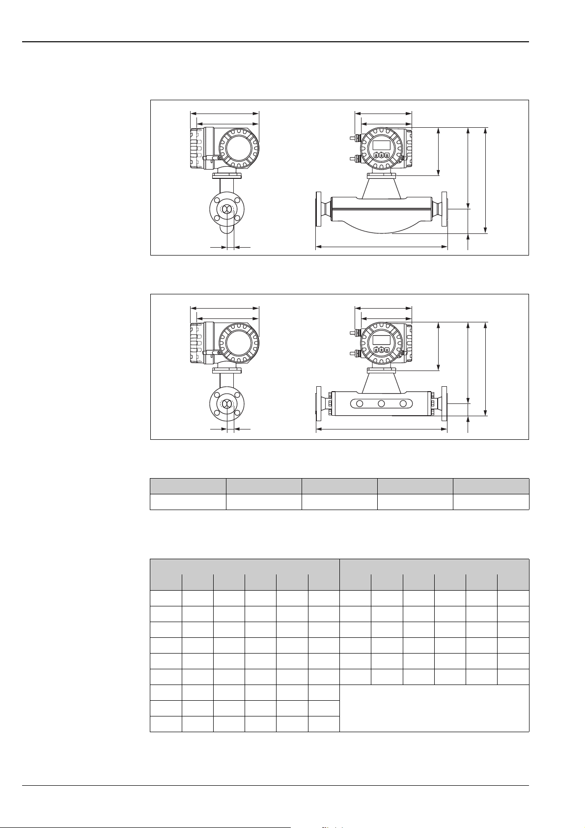
Transmitter compact version, powder coated die-cast aluminium field housing
AB
A* C
D
F
G
E
Promass F
AB
A* C
Promass M
A A* B C D
227 207 187 168 160
All dimensions in [mm]
* Blind version (without display)
di
L
a0003165
D
F
G
E
di
L
a0003165
Promass F Promass M
DN E F G L di DN E F G L di
!
8 75 266 341
15 75 266 341
25 75 266 341
40 105 271 376
50 141 283 424
80 200 305 505
100 247 324 571
150 378 362 740
250 548 390 938
Note!
1) 1)
1) 1)
1) 1)
1) 1)
1) 1)
1) 1)
1) 1)
1) 1)
1) 1)
Dimensions for transmitter II2G/zone 1 → Page 29.
8 35 266 301
15 37 268 305
25 40 272 312
40 49 283 332
50 58 293 351
80 76 309 385
All dimensions in [mm]
1)
depends on the process connection
→ see tables on following pages
1) 1)
1) 1)
1) 1)
1) 1)
1) 1)
1) 1)
28 Endress+Hauser
Page 29
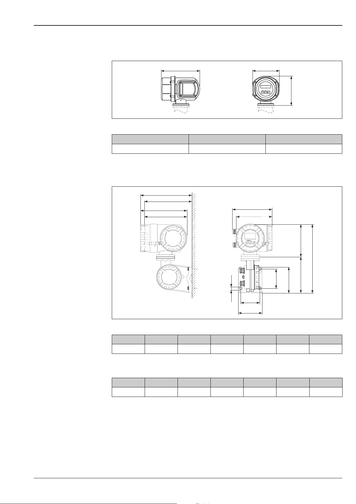
Proline Promass 84F, 84M
Esc
E
- +
Transmitter compact version, stainless steel field housing
A
A B C
225 153 168
All dimensions in [mm]
Transmitter and remote field housing (II2G/zone 1)
A
A*
B
B*
Nicht-eigensichere
Stromkreisedurch
IP40-Abdeckunggeschützt
Non-intrinsicallysafe
circuitsIp40 protected
Bouclesde courant
sanssécurité intrinsèque
protégéespar Ip40
B
Esc
-
+
E
C
a0002245
C
D
S
r
e
p
t
a
n
n
u
n
t
u
h
n
c
i
g
e
n
n
f
N
f
ö
e
l
i
h
e
v
w
i
l
t
a
h
e
g
i
r
t
a
r
s
e
t
i
v
u
o
c
c
r
i
p
c
e
e
K
K
e
e
c
p
i
r
c
c
u
o
i
v
t
s
e
r
a
t
r
i
e
g
h
a
t
l
i
w
v
e
h
i
l
e
n
s
o
i
o
N
l
s
u
s
n
i
t
e
e
e
r
p
a
a
p
s
p
o
a
’
l
u
v
r
r
i
E
J
L
K
F
G
H
A A* B B* C D E
265 242 240 217 206 186 167
* Blind version (without display)
F G H J K L M
∅ 8.6 (M8) 100 123 100 133 188 355
All dimensions in [mm]
M
a0002128
Endress+Hauser 29
Page 30
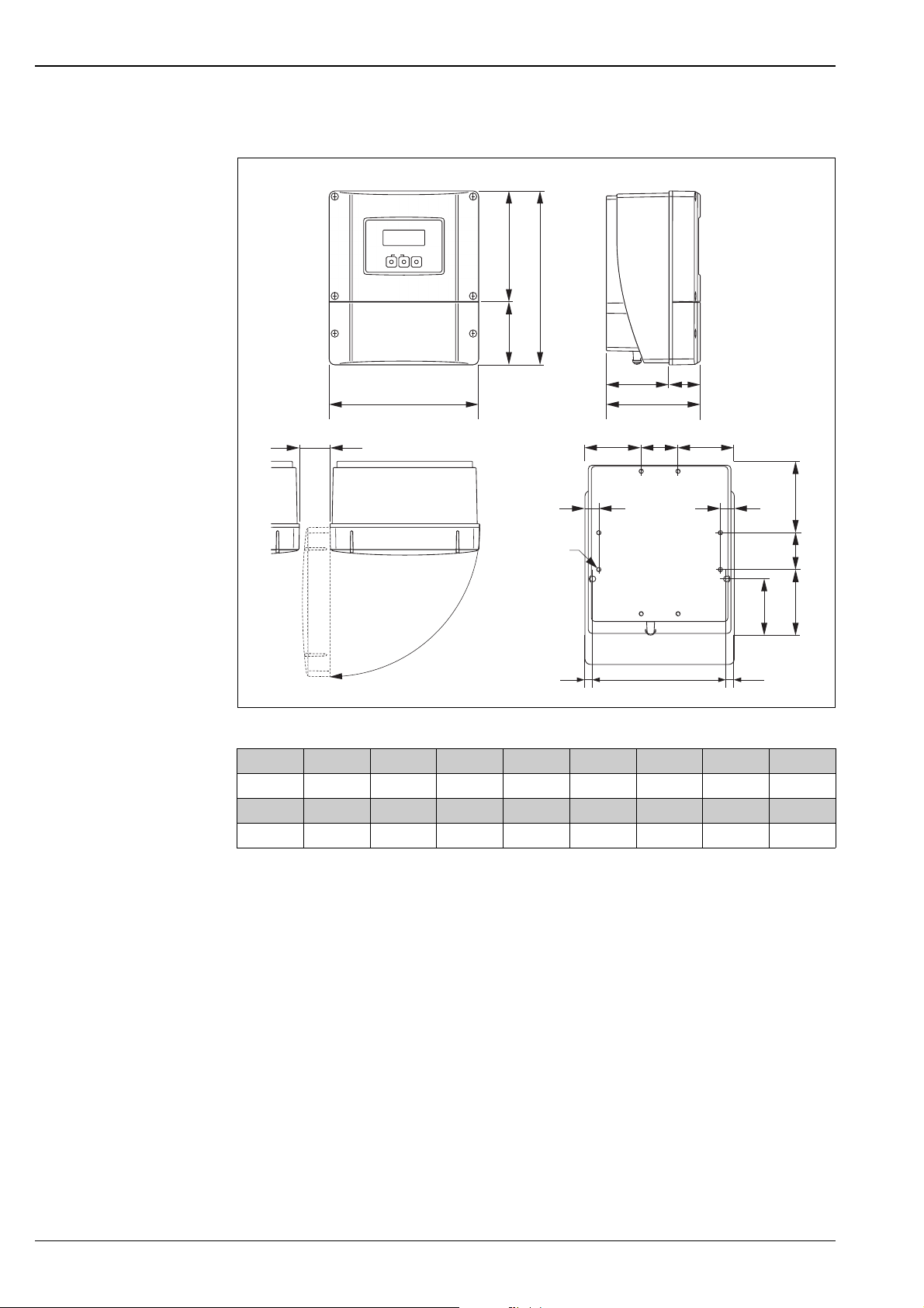
Transmitter wall-mount housing (non hazardous area and II3G/zone 2)
E
-
+
Proline Promass 84F, 84M
Esc
D
B
C
F
A
H J
J
G
E
K
R
PP
Q
N
SS
M
L
O
a0001150
A B C D E F G H J
215 250 90.5 159.5 135 90 45 > 50 81
K L M N O P Q R S
53 95 53 102 81.5 11.5 192 8 × M5 20
All dimensions in [mm]
30 Endress+Hauser
Page 31
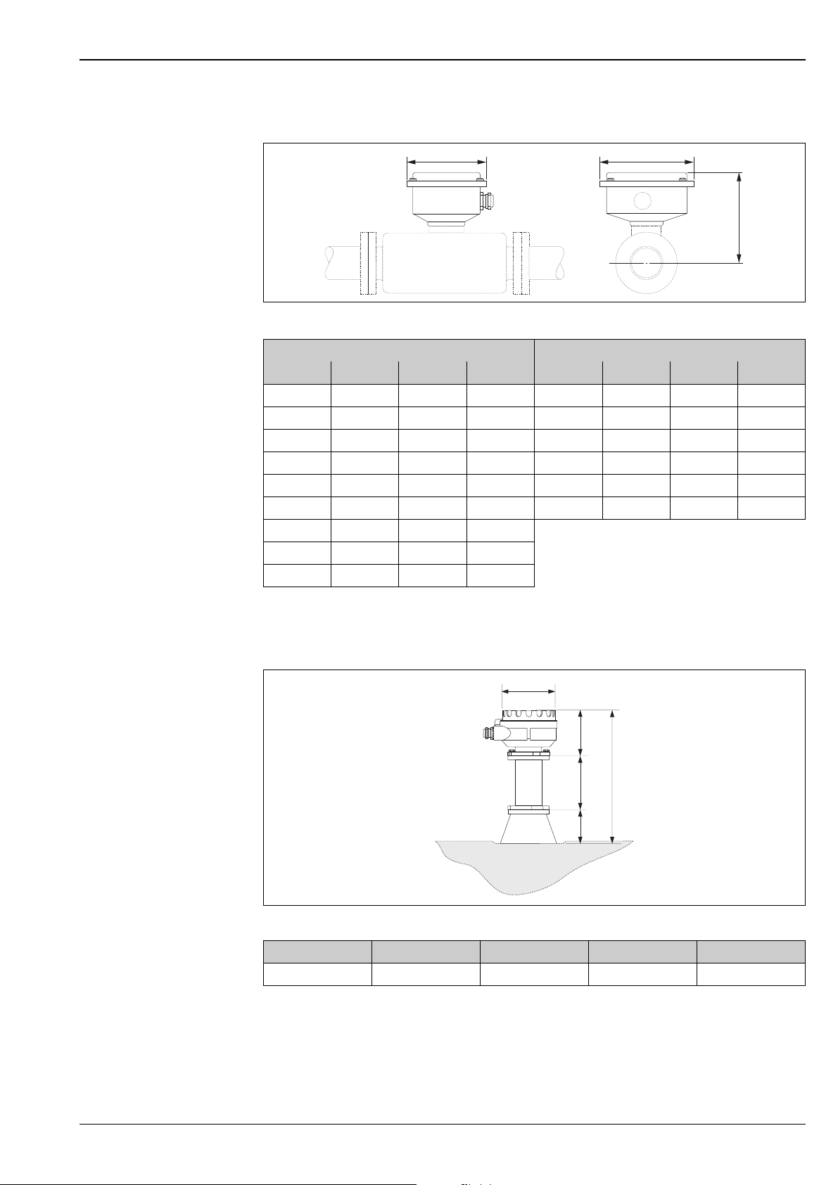
Proline Promass 84F, 84M
Connetion housing remote version
A
Promass F Promass M
DN A B C DN A B C
8 118.5 137.5 113 8 118.5 137.5 113
15 118.5 137.5 113 15 118.5 137.5 115
25 118.5 137.5 113 25 118.5 137.5 119
40 118.5 137.5 118 40 118.5 137.5 130
50 118.5 137.5 130 50 118.5 137.5 140
80 118.5 137.5 152 80 118.5 137.5 156
100 118.5 137.5 171
150 118.5 137.5 209
250 118.5 137.5 237
All dimensions in [mm]
B
C
a0002516
!
Connetion housing remote version for heating
Note!
Use this version in case of insulation or application of heating jacket.
A
D
C
B
A B C D E
129 80 110 102 292
All dimensions in [mm]
E
a0002517
Endress+Hauser 31
Page 32
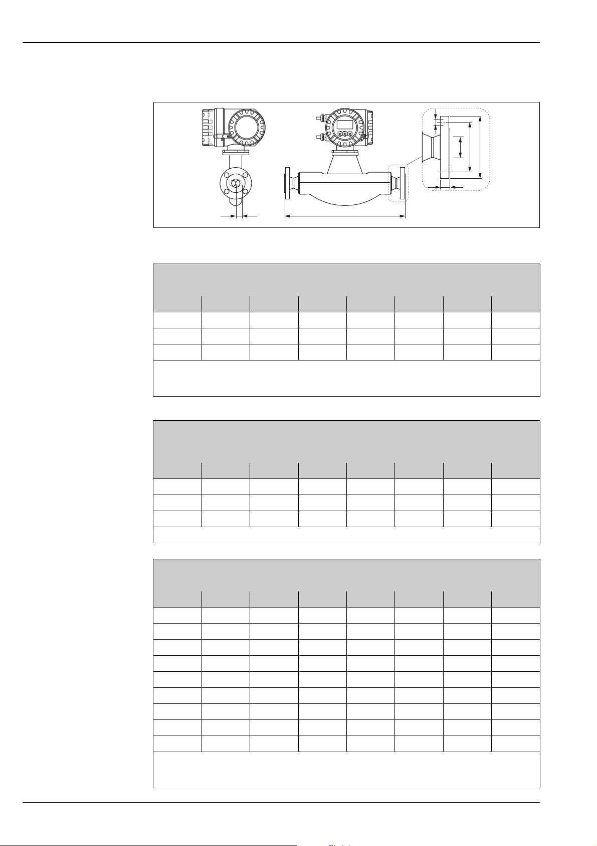
Promass F: Flange connections EN (DIN)
Esc
E
-
+
Proline Promass 84F, 84M
N
U
G
LK
S
di
+1.5*
L
–2.0*
*DN 150…250: ±3.5
Flange according to EN 1092-1 (DIN 2501 / DIN 2512N 1)) / PN 16: 1.4404/316L
Surface roughness (flange): EN 1092-1 Form B1 (DIN 2526 Form C), Ra 3.2 to 12.5 μm
DN G L N S LK U di
100 220 1128 8 × Ø 18 20 180 107.1 51.20
150 285 1330 8 × Ø 22 22 240 159.3 68.90
2)
250
All dimensions in [mm]; Further dimensions → Page 28 ff.
1)
flange with groove according to EN 1092-1 Form D (DIN 2512N) available
2)
not available in Alloy
405 1780 12 × Ø 26 26 355 260.4 102.26
Flange according to EN 1092-1 (DIN 2501 / DIN 2512N) extension - reduction / PN 16: 1.4404/316L
Only for nominal diameter DN 250 (on request)
Surface roughness (flange): Ra 0.8 to 3.2 μm
DN G L N S LK U di
150 285 1980 8 × Ø 22 22 240 159.3 102.26
200 340 1940 12 × Ø 22 24 295 207.3 102.26
300 460 1940 12 × Ø 26 28 410 309.7 102.26
All dimensions in [mm]; Further dimensions → Page 28 ff.
a0002501-en
Flange according to EN 1092-1 (DIN 2501 / DIN 2512N 1)) / PN 40: 1.4404/316L, Alloy C-22
Surface roughness (flange): EN 1092-1 Form B1 (DIN 2526 Form C), Ra 3.2 to 12.5 μm
DN G L N S LK U di
2)
8
95 370 4 × Ø 14 16 65 17.3 5.35
15 95 404 4 × Ø 14 16 65 17.3 8.30
25 115 440 4 × Ø 14 18 85 28.5 12.00
40 150 550 4 × Ø 18 18 110 43.1 17.60
50 165 715 4 × Ø 18 20 125 54.5 26.00
80 200 840 8 × Ø 18 24 160 82.5 40.50
100 235 1128 8 × Ø 22 24 190 107.1 51.20
150 300 1370 8 × Ø 26 28 250 159.3 68.90
3)
250
All dimensions in [mm]; Further dimensions → Page 28 ff.
1)
flange with groove according to EN 1092-1 Form D (DIN 2512N) available
2)
with DN 15 flanges; 3) not available in Alloy
450 1850 12 × Ø 33 38 385 258.8 102.26
32 Endress+Hauser
Page 33
Proline Promass 84F, 84M
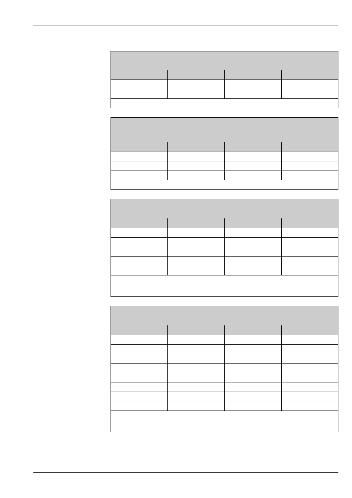
Flange according to EN 1092-1 (DIN 2501) / PN 40 (with DN 25-Flanges): 1.4404/316L
Surface roughness (flange): EN 1092-1 Form B1 (DIN 2526 Form C), Ra 3.2 to 12.5 μm
DN G L N S LK U di
8 115 440 4 × Ø 14 18 85 28.5 5.35
15 115 440 4 × Ø 14 18 85 28.5 8.30
All dimensions in [mm]; Further dimensions → Page 28 ff.
Flange according to EN 1092-1 (DIN 2501 / DIN 2512N) extension - reduction / PN 40: 1.4404/316L
Only for nominal diameter DN 250 (on request)
Surface roughness (flange): Ra 0.8 to 3.2 μm
DN G L N S LK U di
150 300 1980 8 × Ø 26 28 250 159.3 102.26
200 375 1940 12 × Ø 30 34 320 206.5 102.26
300 515 1940 16 × Ø 33 42 450 307.9 102.26
All dimensions in [mm]; Further dimensions → Page 28 ff.
Flange according to EN 1092-1 (DIN 2501 / DIN 2512N 1)) / PN 63: 1.4404/316L, Alloy C-22
Surface roughness (flange): EN 1092-1 Form B2 (DIN 2526 Form E), Ra 0.8 to 3.2 μm
DN G L N S LK U di
50 180 724 4 × Ø 22 26 135 54.5 26.00
80 215 875 8 × Ø 22 28 170 81.7 40.50
100 250 1128 8 × Ø 26 30 200 106.3 51.20
150 345 1410 8 × Ø 33 36 280 157.1 68.90
2)
250
All dimensions in [mm]; Further dimensions → Page 28 ff.
1)
flange with groove according to EN 1092-1 Form D (DIN 2512N) available
2)
not available in Alloy
470 1890 12 × Ø 36 46 400 255.4 102.26
Flange according to EN 1092-1 (DIN 2501 / DIN 2512N 1)) / PN 100: 1.4404/316L, Alloy C-22
Surface roughness (flange): EN 1092-1 Form B2 (DIN 2526 Form E), Ra 0.8 to 3.2 μm
DN G L N S LK U di
2)
8
105 400 4 × Ø 14 20 75 17.3 5.35
15 105 420 4 × Ø 14 20 75 17.3 8.30
25 140 470 4 × Ø 18 24 100 28.5 12.00
40 170 590 4 × Ø 22 26 125 42.5 17.60
50 195 740 4 × Ø 26 28 145 53.9 26.00
80 230 885 8 × Ø 26 32 180 80.9 40.50
100 265 1128 8 × Ø 30 36 210 104.3 51.20
150 355 1450 12 × Ø 33 44 290 154.0 68.90
All dimensions in [mm]; Further dimensions → Page 28 ff.
1)
flange with groove according to EN 1092-1 Form D (DIN 2512N) available
2)
with DN 15 flanges
Endress+Hauser 33
Page 34
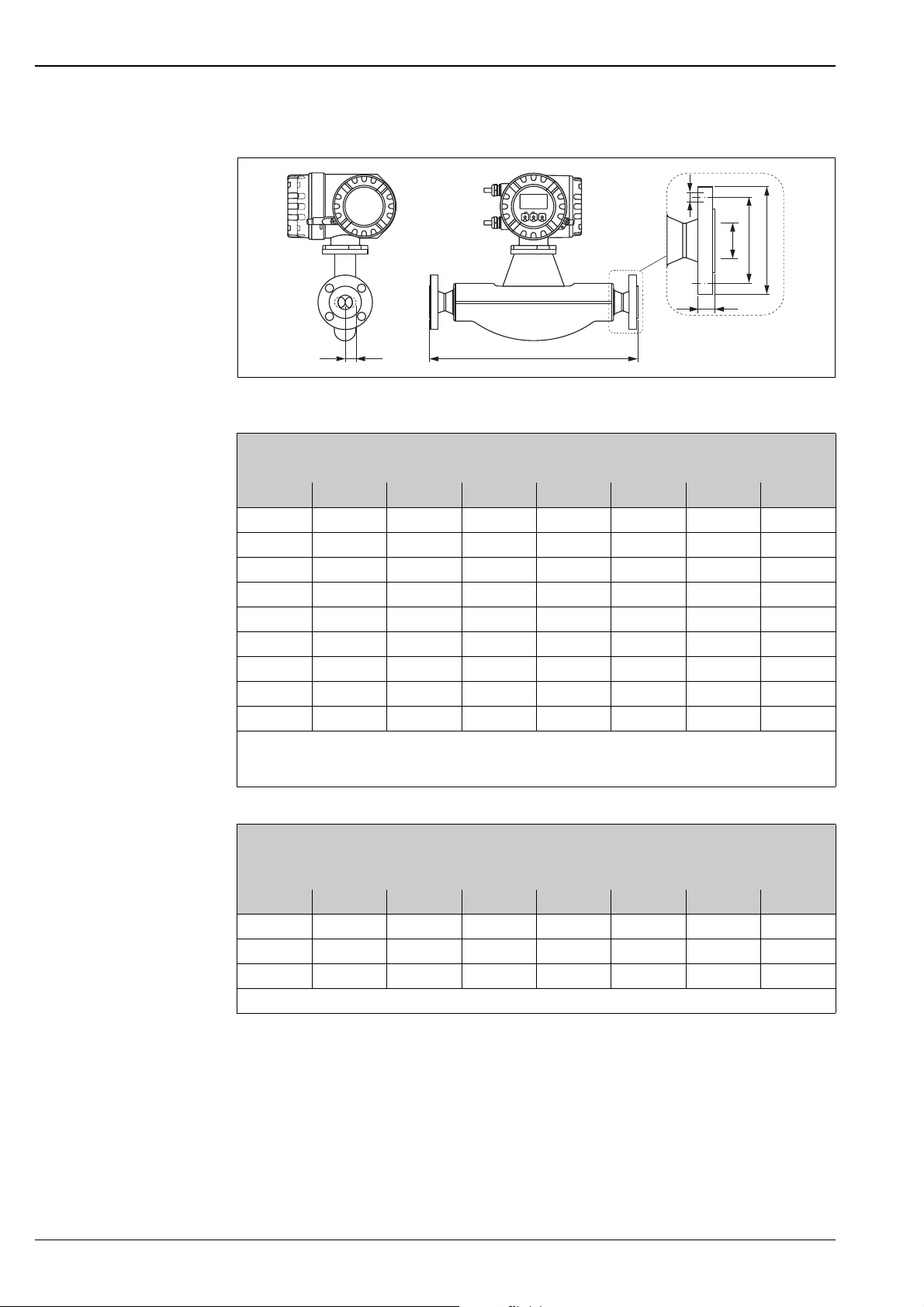
Promass F: Flange connections ASME B16.5
Esc
E
-
+
Proline Promass 84F, 84M
N
U
G
LK
S
di
+1.5*
L
–2.0*
*DN 150…250: ±3.5
Flange according to ASME B16.5 / Cl 150: 1.4404/316L, Alloy C-22
Surface roughness (flange): Ra 3.2 to 6.3 μm
DN G L N S LK U di
1)
8
88.9 370 4 × Ø 15.7 11.2 60.5 15.7 5.35
15 88.9 404 4 × Ø 15.7 11.2 60.5 15.7 8.30
25 108.0 440 4 × Ø 15.7 14.2 79.2 26.7 12.00
40 127.0 550 4 × Ø 15.7 17.5 98.6 40.9 17.60
50 152.4 715 4 × Ø 19.1 19.1 120.7 52.6 26.00
80 190.5 840 4 × Ø 19.1 23.9 152.4 78.0 40.50
100 228.6 1128 8 × Ø 19.1 23.9 190.5 102.4 51.20
150 279.4 1398 8 × Ø 22.4 25.4 241.3 154.2 68.90
2)
250
All dimensions in [mm]; Further dimensions → Page 28 ff.
1)
with DN 15 flanges
2)
not available in Alloy
406.4 1836.8 12 × Ø 25.4 30.2 362 254.5 102.26
a0002501-en
Flange according to ASME B16.5 extension - reduction / Cl 150: 1.4404/316L
Only for nominal diameter DN 250 /10" (on request)
Surface roughness (flange): Ra 3.2 to 6.3 μm
DN G L N S LK U di
150 279.4 1980 8 × Ø 22.4 25.4 241.3 154.2 102.26
200 342.9 1940 8 × Ø 22.4 28.4 298.5 202.7 102.26
300 482.6 1940 12 × Ø 25.4 31.8 431.8 304.80 102.26
All dimensions in [mm]; Further dimensions → Page 28 ff.
34 Endress+Hauser
Page 35
Proline Promass 84F, 84M
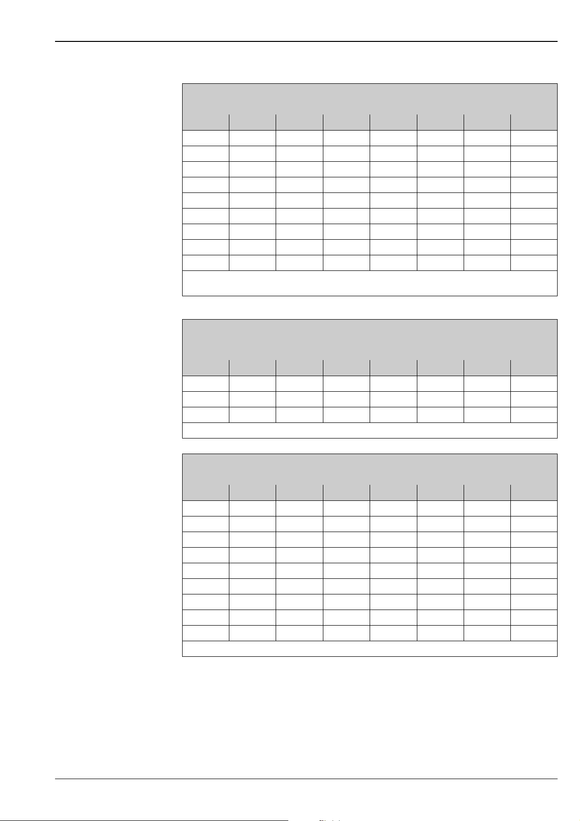
Flange according to ASME B16.5 / Cl 300: 1.4404/316L, Alloy C-22
Surface roughness (flange): Ra 3.2 to 6.3 μm
DN G L N S LK U di
1)
8
95.2 370 4 × Ø 15.7 14.2 66.5 15.7 5.35
15 95.2 404 4 × Ø 15.7 14.2 66.5 15.7 8.30
25 123.9 440 4 × Ø 19.0 17.5 88.9 26.7 12.00
40 155.4 550 4 × Ø 22.3 20.6 114.3 40.9 17.60
50 165.1 715 8 × Ø 19.0 22.3 127.0 52.6 26.00
80 209.5 840 8 × Ø 22.3 28.4 168.1 78.0 40.50
100 254.0 1128 8 × Ø 22.3 31.7 200.1 102.4 51.20
150 317.5 1417 12 × Ø 22.3 36.5 269.7 154.2 68.90
2)
250
All dimensions in [mm]; Further dimensions → Page 28 ff.
1)
with DN 15 flanges; 2) not available in Alloy
444.5 1868.2 16 × Ø 28.4 47.4 387.3 254.5 102.26
Flange according to ASME B16.5 extension - reduction / Cl 300: 1.4404/316
Only for nominal diameter DN 250 /10" (on request)
Surface roughness (flange): Ra 3.2 to 6.3 μm
DN G L N S LK U di
150 317.5 1980 12 × Ø 22.4 36.5 269.7 154.2 102.26
200 381.0 1940 12 × Ø 25.4 41.1 330.2 202.7 102.26
300 520.7 1940 16 × Ø 31.7 50.8 450.8 304.80 102.26
All dimensions in [mm]; Further dimensions → Page 28 ff.
Flange according to ASME B16.5 / Cl 600: 1.4404/316L, Alloy C-22
Surface roughness (flange): Ra 3.2 to 6.3 μm
DN G L N S LK U di
1)
8
95.3 400 4 × Ø 15.7 20.6 66.5 13.9 5.35
15 95.3 420 4 × Ø 15.7 20.6 66.5 13.9 8.30
25 124.0 490 4 × Ø 19.1 23.9 88.9 24.3 12.00
40 155.4 600 4 × Ø 22.4 28.7 114.3 38.1 17.60
50 165.1 742 8 × Ø 19.1 31.8 127.0 49.2 26.00
80 209.6 900 8 × Ø 22.4 38.2 168.1 73.7 40.50
100 273.1 1158 8 × Ø 25.4 48.4 215.9 97.3 51.20
150 355.6 1467 12 × Ø 28.4 47.8 292.1 154.2 68.90
2)
250
All dimensions in [mm]; Further dimensions → Page 28 ff.;
508.0 1951.2 16 × Ø 35.1 69.9 431.8 254.5 102.26
1)
with DN 15 flanges; 2) not available in Alloy
Endress+Hauser 35
Page 36
Proline Promass 84F, 84M
Esc
E
-
+
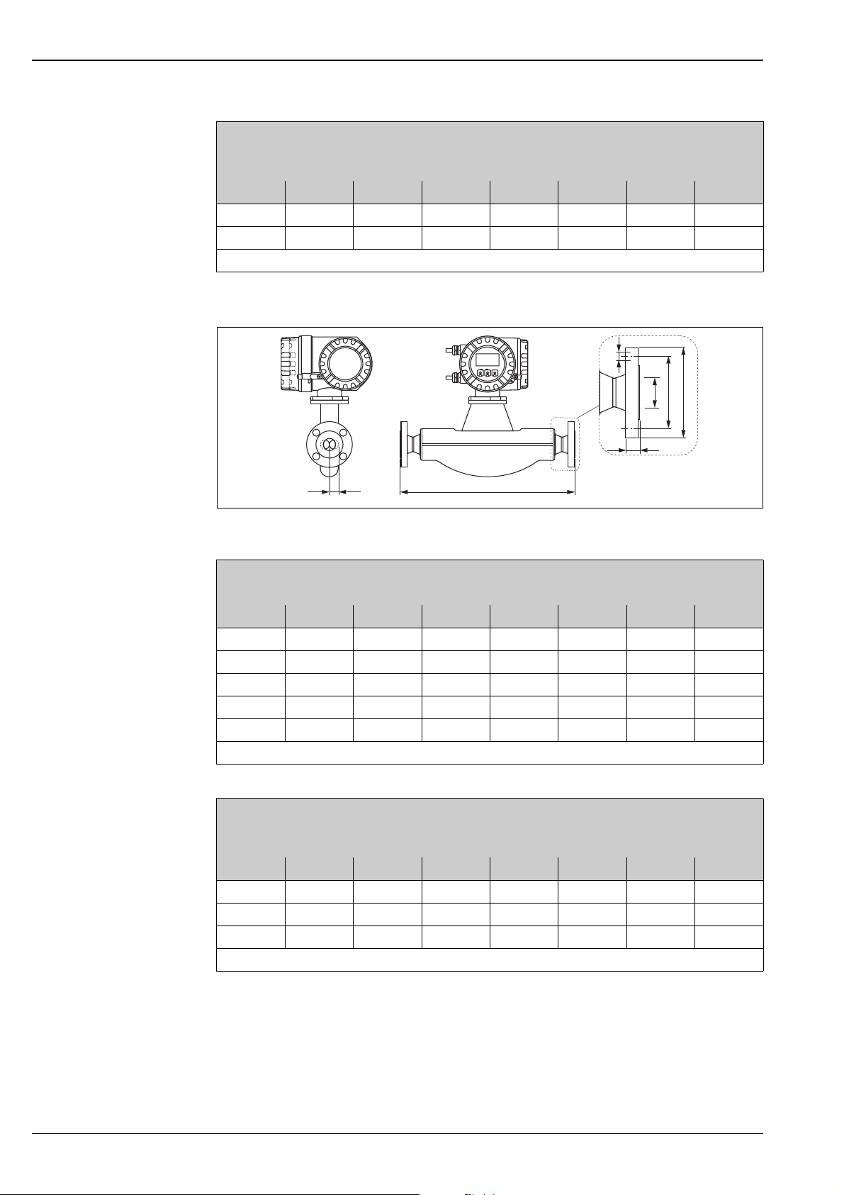
Flange according to ASME B16.5 extension - reduction / Cl 600: 1.4404/316L
Only for nominal diameter DN 250 /10" (on request)
Surface roughness (flange): Ra 3.2 to 6.3 μm
DN G L N S LK U di
150 355.6 1980 12 × Ø 28.4 54.2 292.1 154.2 102.26
200 419.1 1940 12 × Ø 31.8 62.0 349.3 202.7 102.26
All dimensions in [mm]; Further dimensions → Page 28 ff.
Promass F: Flange connections JIS
N
U
G
LK
S
di
+1.5*
L
–2.0*
*DN 150…250: ±3.5
Flange JIS B2220 / 10K: 1.4404/316L, Alloy C-22
Surface roughness (flange): Ra 3.2 to 6.3 μm
DN G L N S LK U di
50 155 715 4 × Ø 19 16 120 50 26.00
80 185 832 8 × Ø 19 18 150 80 40.50
100 210 1128 8 × Ø 19 18 175 100 51.20
150 280 1354 8 × Ø 23 22 240 150 68.90
1)
250
All dimensions in [mm]; Further dimensions → Page 28 ff.;
400 1780 12 × Ø 25 24 355 250 102.26
1)
not available in Alloy
Flange JIS extension - reduction / 10K: 1.4404/316L, Alloy C-22
Only for nominal diameter DN 250 (on request)
Surface roughness (flange): Ra 1.6 to 3.2 μm
DN G L N S LK U di
150 280 1980 8 × Ø 23 22 240 150 102.26
200 330 1940 12 × Ø 23 22 290 200 102.26
300 445 1940 16 × Ø 25 24 400 300 102.26
All dimensions in [mm]; Further dimensions → Page 28 ff.
a0002501-EN
36 Endress+Hauser
Page 37
Proline Promass 84F, 84M
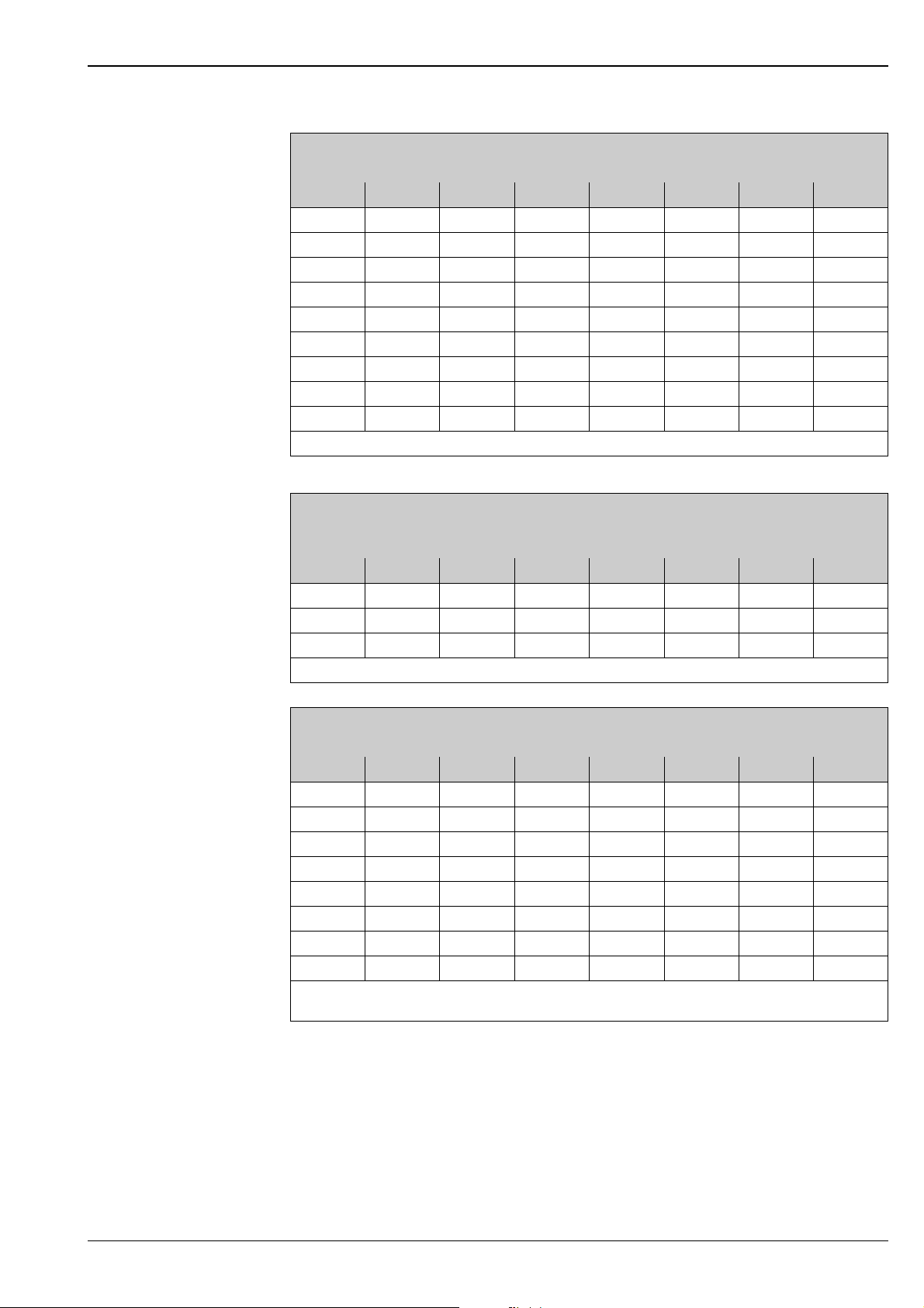
Flange JIS B2220 / 20K: 1.4404/316L, Alloy C-22
Surface roughness (flange): Ra 1.6 to 3.2 μm
DN G L N S LK U di
1)
8
95 370 4 × Ø 15 14 70 15 5.35
15 95 404 4 × Ø 15 14 70 15 8.30
25 125 440 4 × Ø 19 16 90 25 12.00
40 140 550 4 × Ø 19 18 105 40 17.60
50 155 715 8 × Ø 19 18 120 50 26.00
80 200 832 8 × Ø 23 22 160 80 40.50
100 225 1128 8 × Ø 23 24 185 100 51.20
150 305 1386 12 × Ø 25 28 260 150 68.90
2)
250
All dimensions in [mm]; Further dimensions → Page 28 ff.;
430 1850 12 × Ø 27 34 380 250 102.26
1)
with DN 15 flanges; 2) not available in Alloy
Flange JIS extension - reduction / 20K: 1.4404/316L, Alloy C-22
Only for nominal diameter DN 250 (on request)
Surface roughness (flange): Ra 1.6 to 3.2 μm
DN G L N S LK U di
150 305 1980 12 × Ø 25 28 260 150 102.26
200 350 1940 12 × Ø 25 30 305 200 102.26
300 480 1940 16 × Ø 27 36 430 300 102.26
All dimensions in [mm]; Further dimensions → Page 28 ff.
Flange JIS B2220 / 40K: 1.4404/316L, Alloy C-22
Surface roughness (flange): Ra 1.6 to 3.2 μm
DN G L N S LK U di
1)
8
115 400 4 × Ø 19 20 80 15 5.35
15 115 425 4 × Ø 19 20 80 15 8.30
25 130 485 4 × Ø 19 22 95 25 12.00
40 160 600 4 × Ø 23 24 120 38 17.60
50 165 760 8 × Ø 19 26 130 50 26.00
80 210 890 8 × Ø 23 32 170 75 40.50
100 250 1168 8 × Ø 25 36 205 100 51.20
150 355 1498 12 × Ø 33 44 295 150 68.90
All dimensions in [mm]; Further dimensions → Page 28 ff.
1)
with DN 15 flanges
Endress+Hauser 37
Page 38
Proline Promass 84F, 84M
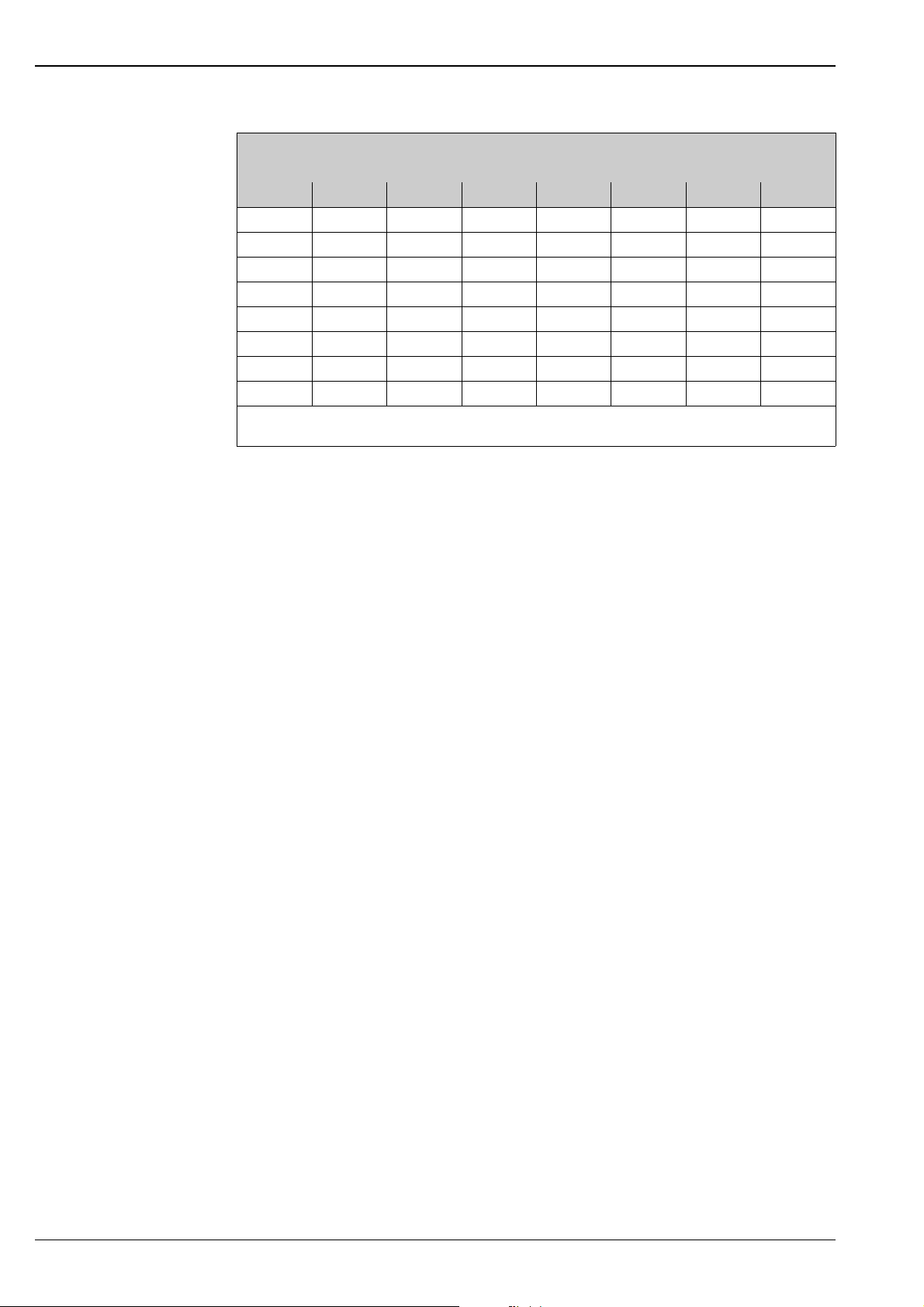
Flange JIS B2220 / 63K: 1.4404/316L, Alloy C-22
Surface roughness (flange): Ra 1.6 to 3.2 μm
DN G L N S LK U di
1)
8
15 120 440 4 × Ø 19 23 85 12 8.30
25 140 494 4 × Ø 23 27 100 22 12.00
40 175 620 4 × Ø 25 32 130 35 17.60
50 185 775 8 × Ø 23 34 145 48 26.00
80 230 915 8 × Ø 25 40 185 73 40.50
100 270 1168 8 × Ø 27 44 220 98 51.20
150 365 1528 12 × Ø 33 54 305 146 68.90
All dimensions in [mm]; Further dimensions → Page 28 ff.
1)
with DN 15 flanges
120 420 4 × Ø 19 23 85 12 5.35
38 Endress+Hauser
Page 39
Proline Promass 84F, 84M
Esc
E
-
+
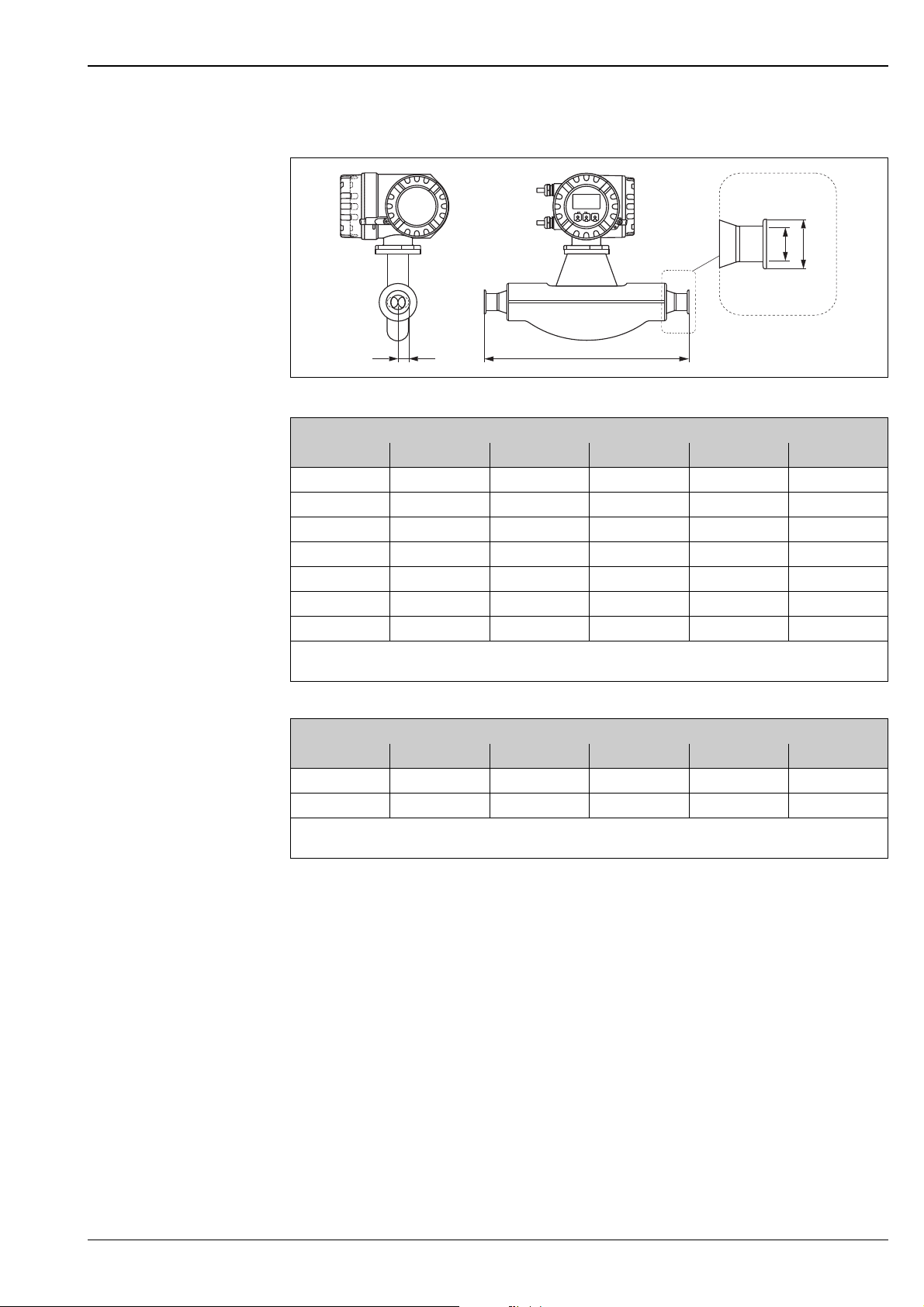
Promass F: Tri-Clamp
U
G
di
+1.5
L
–2.0
Tri-Clamp: 1.4404/316L
DN Clamp G L U di
8 1" 50.4 367 22.1 5.35
15 1" 50.4 398 22.1 8.30
25 1" 50.4 434 22.1 12.00
40 1 ½" 50.4 560 34.8 17.60
50 2" 63.9 720 47.5 26.00
80 3" 90.9 900 72.9 40.50
100 4" 118.9 1128 97.4 51.20
All dimensions in [mm]; Further dimensions → Page 28 ff.
3A version available (Ra ≤ 0.8 μm/150 grit. Option: Ra ≤ 0.4 μm/240 grit)
½"-Tri-Clamp: 1.4404/316L
DN Clamp G L U di
8½"25.03679.55.35
15 ½" 25.0 398 9.5 8.30
All dimensions in [mm]; Further dimensions → Page 28 ff.
3A version available (Ra ≤ 0.8 μm/150 grit. Option: Ra ≤ 0.4 μm/240 grit)
a0002515-en
Endress+Hauser 39
Page 40
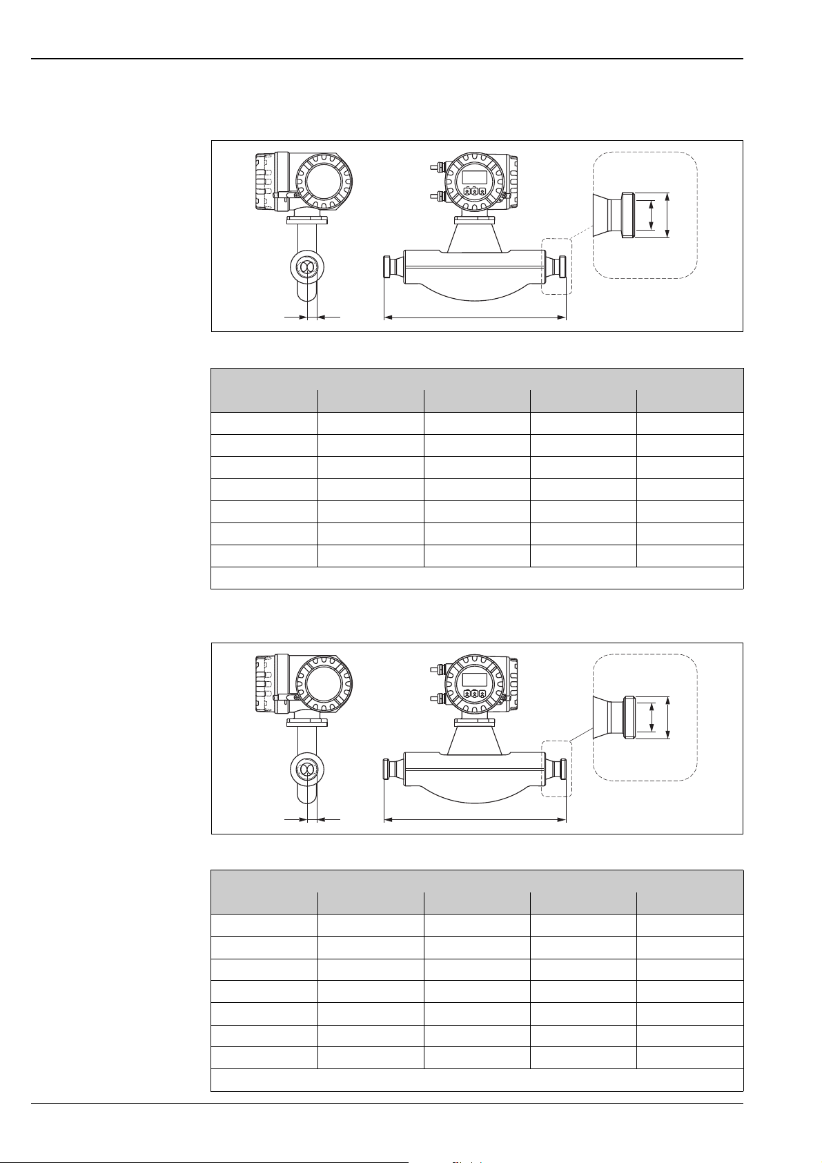
Promass F: DIN 11851 connections (threaded hygienic connection)
Esc
E
-
+
Esc
E
-
+
Proline Promass 84F, 84M
U
G
di
+1.5
L
–2.0
Threaded hygienic connection DIN 11851: 1.4404/316L
DN G L U di
8 Rd 34 × 1/8" 367 16 5.35
15 Rd 34 × 1/8" 398 16 8.30
25 Rd 52 × 1/6" 434 26 12.00
40 Rd 65 × 1/6" 560 38 17.60
50 Rd 78 × 1/6" 720 50 26.00
80 Rd 110 × 1/4" 900 81 40.50
100 Rd 130 × 1/4" 1128 100 51.20
All dimensions in [mm]; Further dimensions → Page 28 ff.; 3A version available (Ra ≤ 0.8 μm/150 grit.)
Promass F: DIN 11864-1 Form A (threaded hygienic connection)
a0002520-en
U
di
+1.5
L
–2.0
Threaded hygienic connection DIN 11864-1 Form A: 1.4404/316L
DN G L U di
8 Rd 28 × 1/8" 367 10 5.35
15 Rd 34 × 1/8" 398 16 8.30
25 Rd 52 × 1/6" 434 26 12.00
40 Rd 65 × 1/6" 560 38 17.60
50 Rd 78 × 1/6" 720 50 26.00
80 Rd 110 × 1/4" 900 81 40.50
100 Rd 130 × 1/4" 1128 100 51.20
All dimensions in [mm]; Further dimensions → Page 28 ff.; 3A version available (Ra ≤ 0.8 μm/150 grit.)
G
a0002521-en
40 Endress+Hauser
Page 41
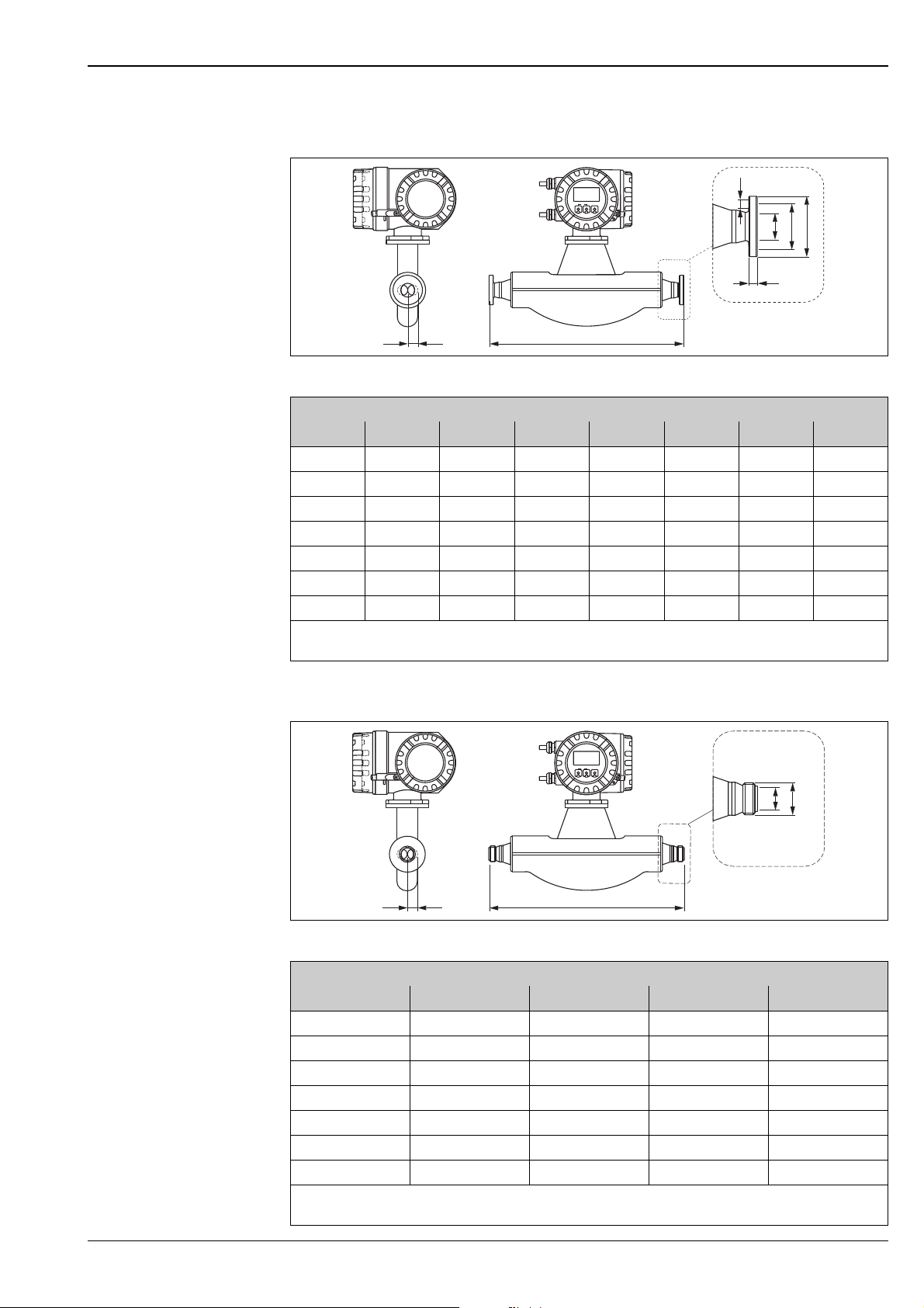
Proline Promass 84F, 84M
Esc
E
-
+
Esc
E
-
+
Promass F: DIN 11864-2 Form A (flat flange with groove)
N
U
G
LK
S
di
+1.5
L
–2.0
DIN 11864-2 Form A (flat fange with groove): 1.4404/316L
DN G L N S LK U di
8543874 × Ø 91037105.35
15 59 418 4 × Ø 9 10 42 16 8.30
25 70 454 4 × Ø 9 10 53 26 12.00
40 82 560 4 × Ø 9 10 65 38 17.60
50 94 720 4 × Ø 9 10 77 50 26.00
80 133 900 8 × Ø 11 12 112 81 40.50
100 159 1128 8 × Ø 11 14 137 100 51.20
All dimensions in [mm]; Further dimensions → Page 28 ff.
3A version available (Ra ≤ 0.8 μm/150 grit. Option: Ra ≤ 0.4 μm/240 grit)
Promass F: ISO 2853 (threaded hygienic connection)
a0002522-en
U
G
di
+1.5
L
–2.0
a0002523-en
Threaded hygienic connection ISO 2853: 1.4404/316L
DN G
1)
L N di
8 37.13 367 22.6 5.35
15 37.13 398 22.6 8.30
25 37.13 434 22.6 12.00
40 52.68 560 35.6 17.60
50 64.16 720 48.6 26.00
80 91.19 900 72.9 40.50
100 118.21 1128 97.6 51.20
1)
All dimensions in [mm]; Further dimensions → Page 28 ff.;
Max. thread diameter to ISO 2853 Annex A
3A version available (Ra ≤ 0.8 μm/150 grit. Option: Ra ≤ 0.4 μm/240 grit)
Endress+Hauser 41
Page 42
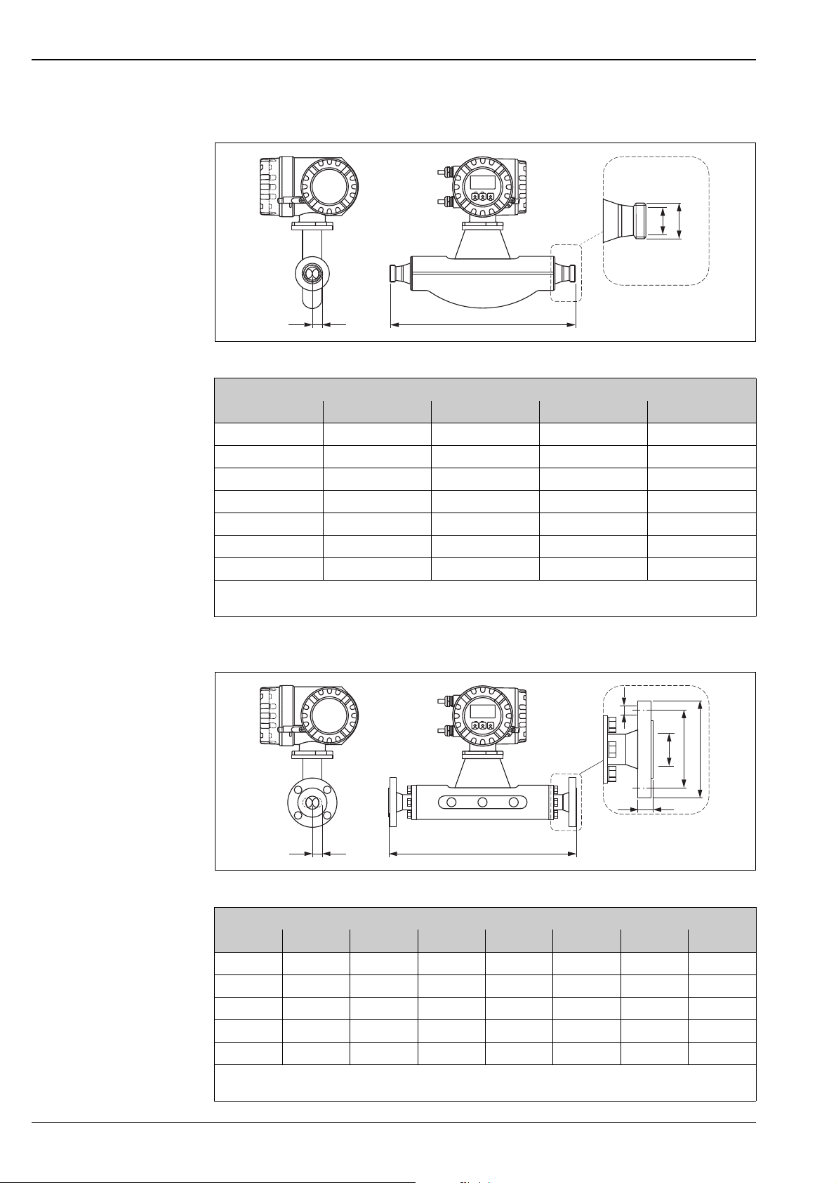
Promass F: SMS 1145 (threaded hygienic connection)
Esc
E
-
+
Esc
E
-
+
Proline Promass 84F, 84M
U
G
di
+1.5
L
–2.0
threaded hygienic connection SMS 1145: 1.4404/316L
DN G L U di
8 Rd 40 x 1/6" 367 22.6 5.35
15 Rd 40 x 1/6" 398 22.6 8.30
25 Rd 40 x 1/6" 434 22.6 12.00
40 Rd 60 x 1/6" 560 35.6 17.60
50 Rd 70 x 1/6" 720 48.6 26.00
80 Rd 98 x 1/6" 900 72.9 40.50
100 Rd 132 x 1/6" 1128 97.6 51.20
All dimensions in [mm]; Further dimensions → Page 28 ff.
3A version available (Ra ≤ 0.8 μm/150 grit. Option: Ra ≤ 0.4 μm/240 grit)
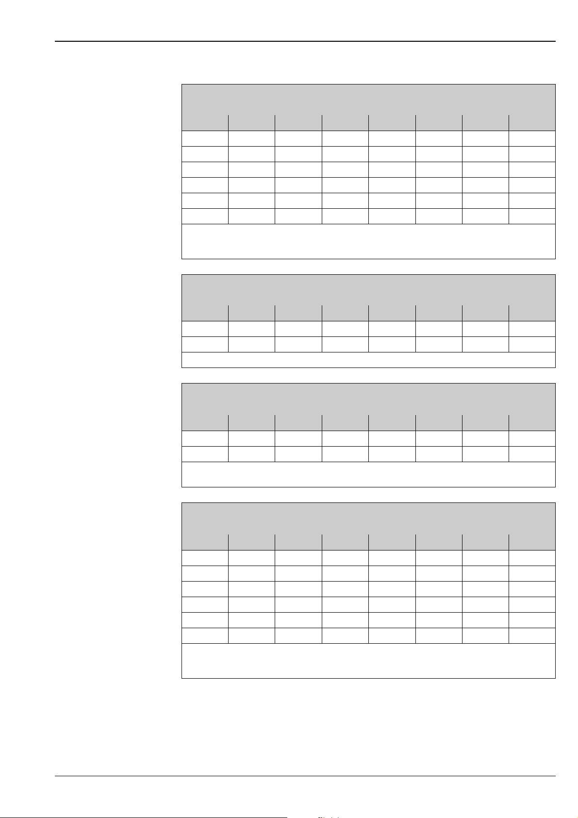
Promass M: Flange connections EN (DIN)
a0002524-en
N
U
G
LK
S
di
+1.5
L
–2.0
a0002525-en
Flange according to EN 1092-1 (DIN 2501) / PN 16: PVDF
DN G L N S LK U di
1)
8
95 370 4 × Ø 14 16 65 16.1 5.53
15 95 404 4 × Ø 14 16 65 16.1 8.55
25 115 440 4 × Ø 14 18 85 28.5 11.38
40 150 550 4 × Ø 18 18 110 43.1 17.07
50 165 715 4 × Ø 18 20 125 54.5 25.60
All dimensions in [mm]; Further dimensions → Page 28 ff.
1)
with DN 15 flanges
42 Endress+Hauser
Page 43
Proline Promass 84F, 84M
Flange according to EN 1092-1 (DIN 2501 / DIN 2512N
1)
) / PN 40: 1.4404/316L, Titan
Surface roughness (flange): EN 1092-1 Form B1 (DIN 2526 Form C), Ra 3.2 to 12.5 μm
DN G L N S LK U di
2)
8
95 370 4 × Ø 14 16 65 17.3 5.53
15 95 404 4 × Ø 14 16 65 17.3 8.55
25 115 440 4 × Ø 14 18 85 28.5 11.38
40 150 550 4 × Ø 18 18 110 43.1 17.07
50 165 715 4 × Ø 18 20 125 54.5 25.60
80 200 840 8 × Ø 18 24 160 82.5 38.46
All dimensions in [mm]; Further dimensions → Page 28 ff.
1)
flange with groove according to EN 1092-1 Form D (DIN 2512N) available
2)
with DN 15 flanges
Flange according to EN 1092-1 (DIN 2501) / PN 40 (mit DN 25-Flanges): 1.4404/316L
Surface roughness (flange): EN 1092-1 Form B1 (DIN 2526 Form C), Ra 0.8 to 12.5 μm
DN G L N S LK U di
8 115 440 4 × Ø 14 18 85 28.5 5.53
15 115 440 4 × Ø 14 18 85 28.5 8.55
All dimensions in [mm]; Further dimensions → Page 28 ff.
Flange according to EN 1092-1 (DIN 2501 / DIN 2512N 1)) / PN 63: 1.4404/316L, Titan
Surface roughness (flange): EN 1092-1 Form B2 (DIN 2526 Form E), Ra 0.8 to 3.2 μm
DN G L N S LK U di
50 180 724 4 × Ø 22 26 135 54.5 25.60
80 215 875 8 × Ø 22 28 170 81.7 38.46
All dimensions in [mm]; Further dimensions → Page 28 ff.
1)
flange with groove according to EN 1092-1 Form D (DIN 2512N) available
Flange according to EN 1092-1 (DIN 2501 / DIN 2512N 1)) / PN 100: 1.4404/316L, Titan
Surface roughness (flange): EN 1092-1 Form B2 (DIN 2526 Form E), Ra 0.8 to 3.2 μm
DN G L N S LK U di
2)
8
95 400 4 × Ø 14 20 65 17.3 5.53
15 95 420 4 × Ø 14 20 65 17.3 8.55
25 115 470 4 × Ø 14 24 85 28.5 11.38
40 150 590 4 × Ø 18 26 110 43.1 17.07
50 165 740 4 × Ø 18 28 125 54.5 25.60
80 230 885 8 × Ø 26 32 180 80.9 38.46
All dimensions in [mm]; Further dimensions → Page 28 ff.
1)
flange with groove according to EN 1092-1 Form D (DIN 2512N) available
2)
with DN 15 flanges
Endress+Hauser 43
Page 44
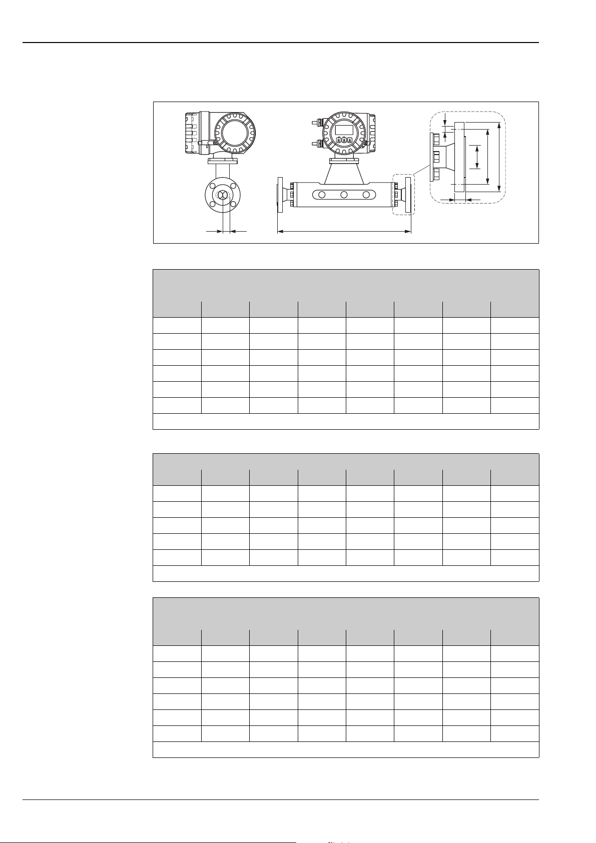
Promass M: Flange connections ASME B16.5
Esc
E
-
+
Proline Promass 84F, 84M
N
U
G
LK
S
di
+1.5
L
–2.0
Flange according to ASME B16.5 / Cl 150: 1.4404/316L, Titan
Surface roughness (flange): Ra 3.2 to 6.3 μm
DN G L N S LK U di
1)
8
88.9 370 4 × Ø 15.7 11.2 60.5 15.7 5.53
15 88.9 404 4 × Ø 15.7 11.2 60.5 15.7 8.55
25 108.0 440 4 × Ø 15.7 14.2 79.2 26.7 11.38
40 127.0 550 4 × Ø 15.7 17.5 98.6 40.9 17.07
50 152.4 715 4 × Ø 19.1 19.1 120.7 52.6 25.60
80 190.5 840 4 × Ø 19.1 23.9 152.4 78.0 38.46
All dimensions in [mm]; Further dimensions → Page 28 ff.;
1)
with DN 15 flanges
Flange according to ASME B16.5 / Cl 150: PVDF
DN G L N S LK U di
1)
8
88.9 370 4 × Ø 15.7 16 60.5 15.7 5.53
15 88.9 404 4 × Ø 15.7 16 60.5 15.7 8.55
25 108.0 440 4 × Ø 15.7 18 79.2 26.7 11.38
40 127.0 550 4 × Ø 15.7 21 98.6 40.9 17.07
50 152.4 715 4 × Ø 19.1 28 120.7 52.6 25.60
All dimensions in [mm]; Further dimensions → Page 28 ff.;
1)
with DN 15 flanges
a0002525-en
Flange according to ASME B16.5 / Cl 300: 1.4404/316L, Titan
Surface roughness (flange): Ra 3.2 to 6.3 μm
DN G L N S LK U di
1)
8
95.2 370 4 × Ø 15.7 14.2 66.5 15.7 5.53
15 95.2 404 4 × Ø 15.7 14.2 66.5 15.7 8.55
25 123.9 440 4 × Ø 19.0 17.5 88.9 26.7 11.38
40 155.4 550 4 × Ø 22.3 20.6 114.3 40.9 17.07
50 165.1 715 8 × Ø 19.0 22.3 127.0 52.6 25.60
80 209.5 840 8 × Ø 22.3 28.4 168.1 78.0 38.46
All dimensions in [mm]; Further dimensions → Page 28 ff.;
1)
with DN 15 flanges
44 Endress+Hauser
Page 45
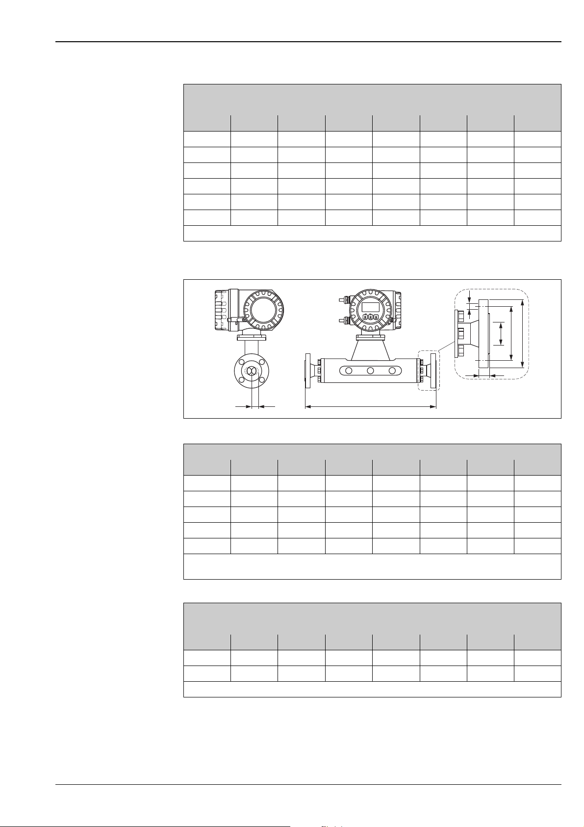
Proline Promass 84F, 84M
Esc
E
-
+
Flange according to ASME B16.5 / Cl 600: 1.4404/316L, Titan
Surface roughness (flange): Ra 3.2 to 6.3 μm
DN G L N S LK U di
8 95.3 400 4 × Ø 15.7 20.6 66.5 13.8 5.53
15 95.3 420 4 × Ø 15.7 20.6 66.5 13.8 8.55
25 124.0 490 4 × Ø 19.1 23.6 88.9 24.4 11.38
40 155.4 600 4 × Ø 22.4 28.7 114.3 38.1 17.07
50 165.1 742 8 × Ø 19.1 31.8 127.0 49.3 25.60
80 209.6 900 8 × Ø 22.4 38.2 168.1 73.7 38.46
All dimensions in [mm]; Further dimensions → Page 28 ff.
Promass M: Flange connections JIS
N
U
S
di
+1.5
L
–2.0
Flange JIS B2220 / 10K: 1.4404/316L, PVDF
DN G L N S LK U di
1)
8
95 370 4 × Ø 15 16 70 15 5.53
15 95 404 4 × Ø 15 16 70 15 8.55
25 125 440 4 × Ø 19 18 90 25 11.38
40 140 550 4 × Ø 19 21 105 40 17.07
50 155 715 4 × Ø 19 22 120 50 25.60
All dimensions in [mm]; Further dimensions → Page 28 ff.
1)
with DN 15 flanges
Flange JIS B2220 / 10K: 1.4404/316L, Titan
Surface roughness (flange): Ra 3.2 to 6.3 μm
DN G L N S LK U di
50 155 715 4 × Ø 19 16 120 50 25.60
80 185 832 8 × Ø 19 18 150 80 38.46
All dimensions in [mm]; Further dimensions → Page 28 ff.
LK
G
a0002525-en
Endress+Hauser 45
Page 46
Proline Promass 84F, 84M
Flange JIS B2220 / 20K: 1.4404/316L, Titan
Surface roughness (flange): Ra 3.2 to 6.3 μm
DN G L N S LK U di
1)
8
15 95 404 4 × Ø 15 16 70 15 8.55
25 125 440 4 × Ø 19 18 90 25 11.38
40 140 550 4 × Ø 19 21 105 40 17.07
50 155 715 4 × Ø 19 22 120 50 25.60
80 200 832 8 × Ø 23 22 160 80 38.46
All dimensions in [mm]; Further dimensions → Page 28 ff.
1)
with DN 15 flanges
Flange JIS B2220 / 40K: 1.4404/316L, Titan
Surface roughness (flange): Ra 3.2 to 6.3 μm
DN G L N S LK U di
1)
8
15 115 425 4 × Ø 19 20 80 15 8.55
25 130 485 4 × Ø 19 22 95 25 11.38
40 160 600 4 × Ø 23 24 120 38 17.07
50 165 760 8 × Ø 19 26 130 50 25.60
80 210 890 8 × Ø 23 32 170 75 38.46
All dimensions in [mm]; Further dimensions → Page 28 ff.
1)
with DN 15 flanges
95 370 4 × Ø 15 16 70 15 5.53
115 400 4 × Ø 19 20 80 15 5.53
Flange JIS B2220 / 63K: 1.4404/316L, Titan
Surface roughness (flange): Ra 3.2 to 6.3 μm
DN G L N S LK U di
1)
8
120 420 4 × Ø 19 23 85 12 5.53
15 120 440 4 × Ø 19 23 85 12 8.55
25 140 494 4 × Ø 23 27 100 22 11.38
40 175 620 4 × Ø 25 32 130 35 17.07
50 185 775 8 × Ø 23 34 145 48 25.60
80 230 915 8 × Ø 25 40 185 73 38.46
All dimensions in [mm]; Further dimensions → Page 28 ff.
1)
with DN 15 flanges
46 Endress+Hauser
Page 47
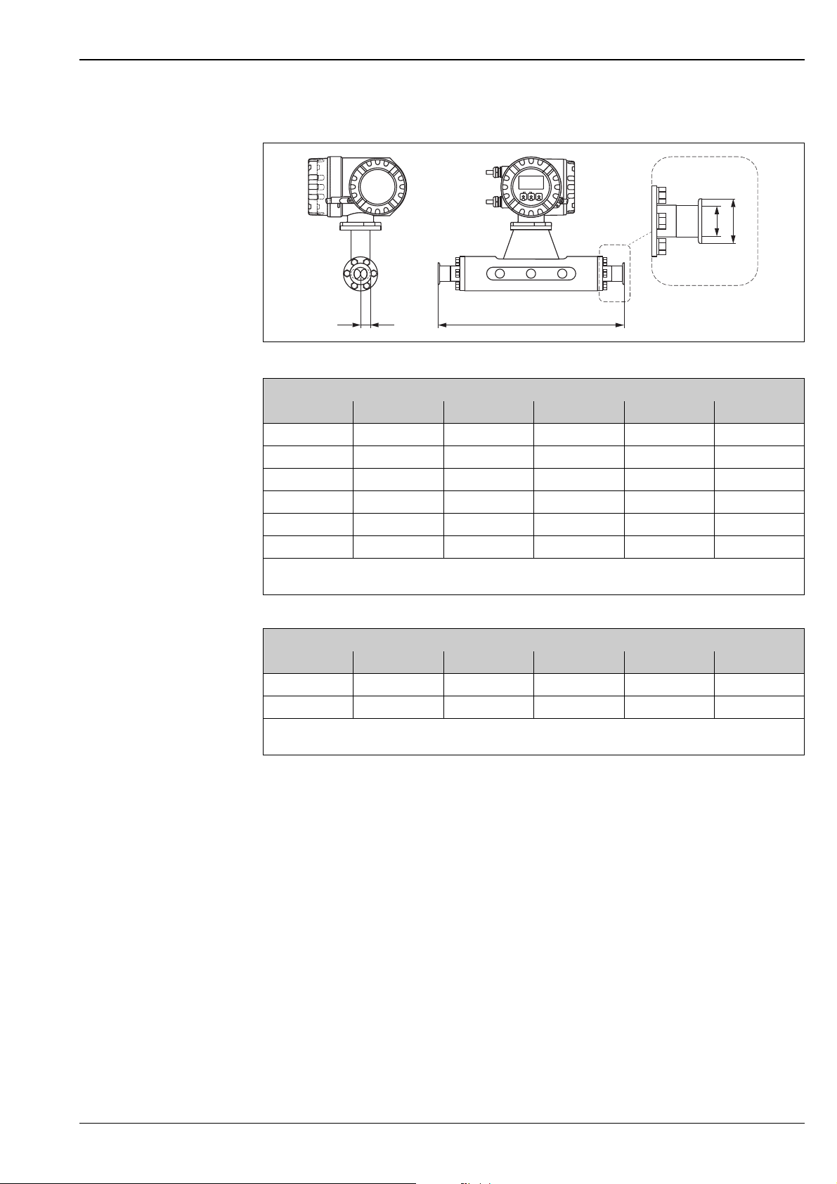
Proline Promass 84F, 84M
Esc
E
-
+
Promass M: Tri-Clamp
U
G
di
+1.5
L
–2.0
Tri-Clamp: 1.4404/316L
DN Clamp G L U di
8 1" 50.4 367 22.1 5.53
15 1" 50.4 398 22.1 8.55
25 1" 50.4 434 22.1 11.38
40 1 ½" 50.4 560 34.8 17.07
50 2" 63.9 720 47.5 25.60
80 3" 90.9 801 72.9 38.46
All dimensions in [mm]; Further dimensions → Page 28 ff.
3A version available (Ra ≤ 0.8 μm/150 grit)
½"-Tri-Clamp: 1.4404/316L
DN Clamp G L U di
8½"25.03679.55.53
15 ½" 25.0 398 9.5 8.55
All dimensions in [mm]; Further dimensions → Page 28 ff.
3A version available (Ra ≤ 0.8 μm/150 grit)
a0002526-en
Endress+Hauser 47
Page 48
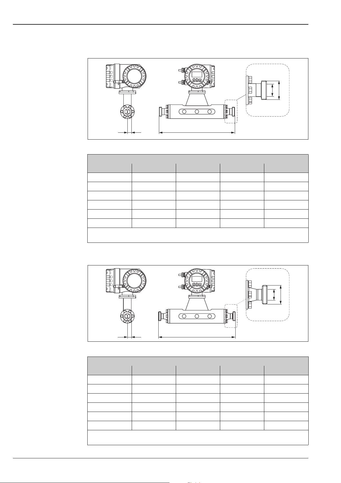
Promass M: DIN 11851 (threaded hygienic connection)
Esc
E
-
+
Esc
E
-
+
Proline Promass 84F, 84M
U
G
di
+1.5
L
–2.0
Threaded hygienic connection DIN 11851: 1.4404/316L
DN G L U di
8 Rd 34 × 1/8" 367 16 5.53
15 Rd 34 × 1/8" 398 16 8.55
25 Rd 52 × 1/6" 434 26 11.38
40 Rd 65 × 1/6" 560 38 17.07
50 Rd 78 × 1/6" 720 50 25.60
80 Rd 110 × 1/4" 815 81 38.46
All dimensions in [mm]; Further dimensions → Page 28 ff.
3A version available (Ra ≤ 0.8 μm/150 grit.)
Promass M: DIN 11864-1 Form A (threaded hygienic connection)
a0002527-en
di
+1.5
L
–2.0
DIN 11864-1 Form A (threaded hygienic connection): 1.4404/316L
DN G L U di
8 Rd 28x 1/8" 367 10 5.53
15 Rd 34 × 1/8" 398 16 8.55
25 Rd 52 × 1/6" 434 26 11.38
40 Rd 65 × 1/6" 560 38 17.07
50 Rd 78 × 1/6" 720 50 25.60
80 Rd 110 × 1/4" 815 81 38.46
All dimensions in [mm]; Further dimensions → Page 28 ff.
3A version available (Ra ≤ 0.8 μm/150 grit.)
U
G
a0002528-en
48 Endress+Hauser
Page 49
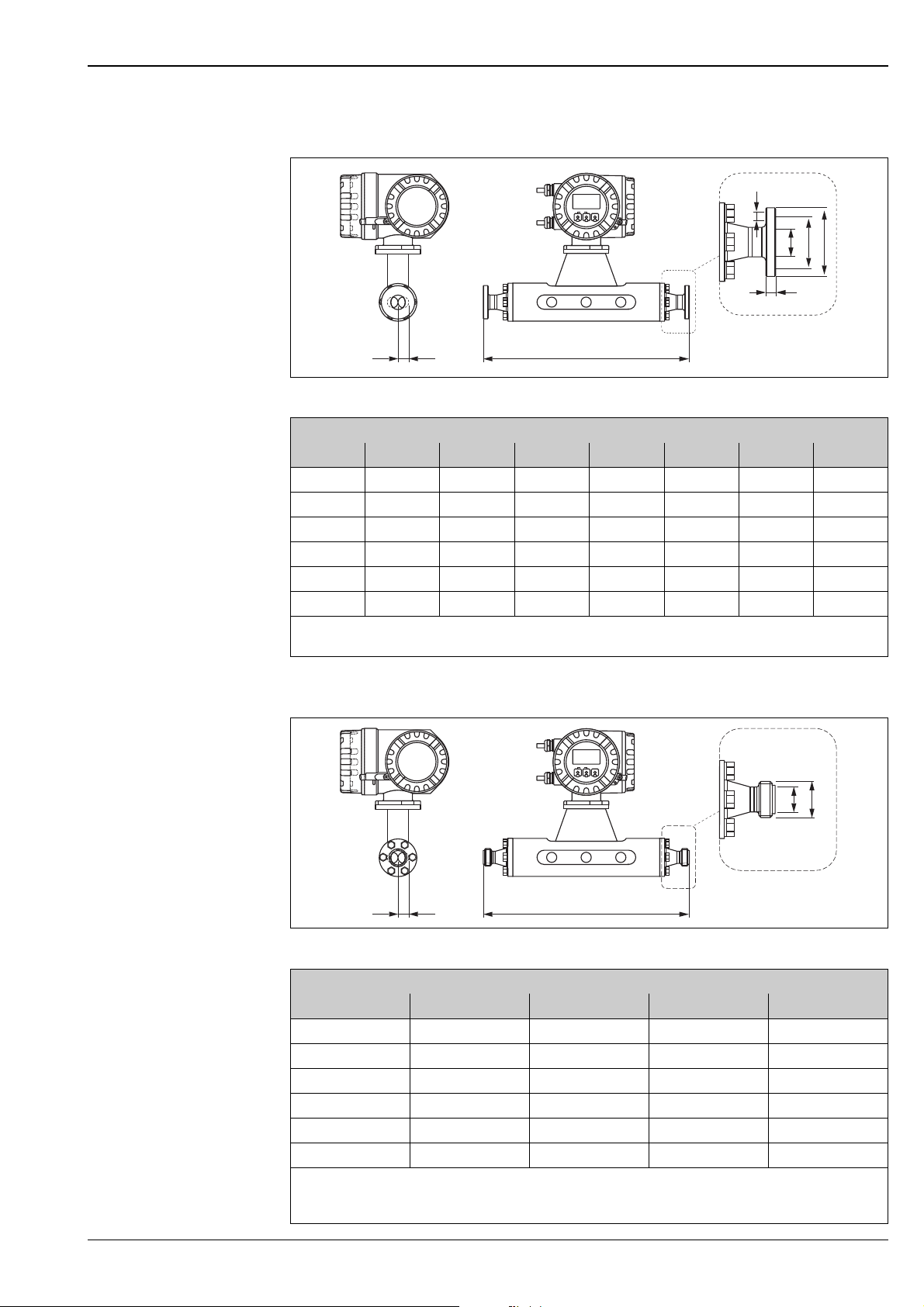
Proline Promass 84F, 84M
Esc
E
-
+
Esc
E
-
+
Promass M: DIN 11864-2 Form A (flat flange with groove)
N
U
G
LK
S
di
+1.5
L
–2.0
DIN 11864-2 Form A (flat flange with groove): 1.4404/316L
DN G L N S LK U di
8543674 × Ø 91037105.53
15 59 398 4 × Ø 9 10 42 16 8.55
25 70 434 4 × Ø 9 10 53 26 11.38
40 82 560 4 × Ø 9 10 65 38 17.07
50 94 720 4 × Ø 9 10 77 50 25.60
80 133 815 8 × Ø 11 12 112 81 38.46
All dimensions in [mm]; Further dimensions → Page 28 ff.
3A version available (Ra ≤ 0.8 μm/150 grit)
Promass M: ISO 2853 (threaded hygienic connection)
a0002529-en
U
G
di
+1.5
L
–2.0
a0002530-en
Threaded hygienic connection ISO 2853: 1.4404/316L
DN G
1)
L N di
8 37.13 367 22.6 5.53
15 37.13 398 22.6 8.55
25 37.13 434 22.6 11.38
40 52.68 560 35.6 17.07
50 64.16 720 48.6 25.60
All dimensions in [mm]; Further dimensions → Page 28 ff.
1)
80 91.19 815 72.9 38.46
Max. thread diameter to ISO 2853 Annex A
3A version available (Ra ≤ 0.8 μm/150 grit)
Endress+Hauser 49
Page 50
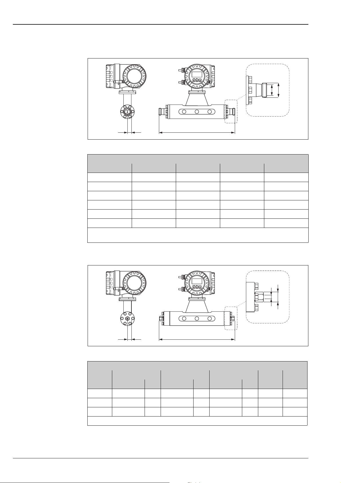
Promass M: SMS 1145 (threaded hygienic connection)
Esc
E
-
+
Esc
E
-
+
Proline Promass 84F, 84M
U
G
di
+1.5
L
–2.0
Threaded hygienic connection SMS 1145: 1.4404/316L
DN G L U di
8 Rd 40 × 1/6" 367 22.5 5.53
15 Rd 40 × 1/6" 398 22.5 8.55
25 Rd 40 × 1/6" 434 22.5 11.38
40 Rd 60 × 1/6" 560 35.5 17.07
50 Rd 70 × 1/6" 720 48.5 25.60
80 Rd 98 × 1/6" 792 72.0 38.46
All dimensions in [mm]; Further dimensions → Page 28 ff.
3A version available (Ra ≤ 0.8 μm/150 grit)
Promass M (high pressure): ½"-NPT, 3/8"-NPT and G 3/8"
a0002531-en
U
di
+1.5
L
–2.0
NPT, G 3/8": 1.4404/316L
DN ½" NPT 3/8" NPT G 3/8" U di
G L G L G L
8 SW 1 1/16" 370 SW 1 5/16" 355.8 SW 24 355.8 10.2 4.93
15 SW 1 1/16" 400 SW 1 5/16" 385.8 SW 24 385.8 10.2 7.75
25 SW 1 1/16" 444 SW 1 5/16" 429.8 SW 24 429.8 10.2 10.20
All dimensions in [mm]; Further dimensions → Page 28 ff.
G
a0002532-en
50 Endress+Hauser
Page 51
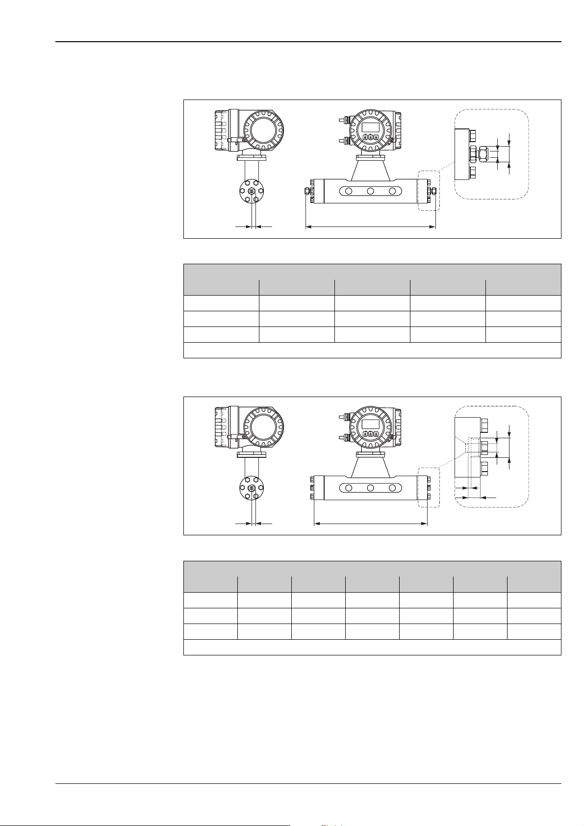
Proline Promass 84F, 84M
Esc
E
-
+
Esc
E
-
+
Promass M (high pressure): ½"-SWAGELOK
U
G
di
+1.5
L
–2.0
½"-SWAGELOK: 1.4404/316L
DN G L U di
8 7/8" 366.4 10.2 4.93
15 7/8" 396.4 10.2 7.75
25 7/8" 440.4 10.2 10.20
All dimensions in [mm]; Further dimensions → Page 28 ff.
Promass M (high pressure): Connector with internal thread 7/8-14UNF
a0002533-en
U
G
V
W
+1.5
L
di
–2.0
a0002534-en
Internal thread 7/8-14-UNF: 1.4404/316L
DN G L U V W di
8 7/8-14UNF 304 10.2 3 14 4.93
15 7/8-14UNF 334 10.2 3 14 7.75
25 7/8-14UNF 378 10.2 3 14 10.20
All dimensions in [mm]; Further dimensions → Page 28 ff.
Endress+Hauser 51
Page 52
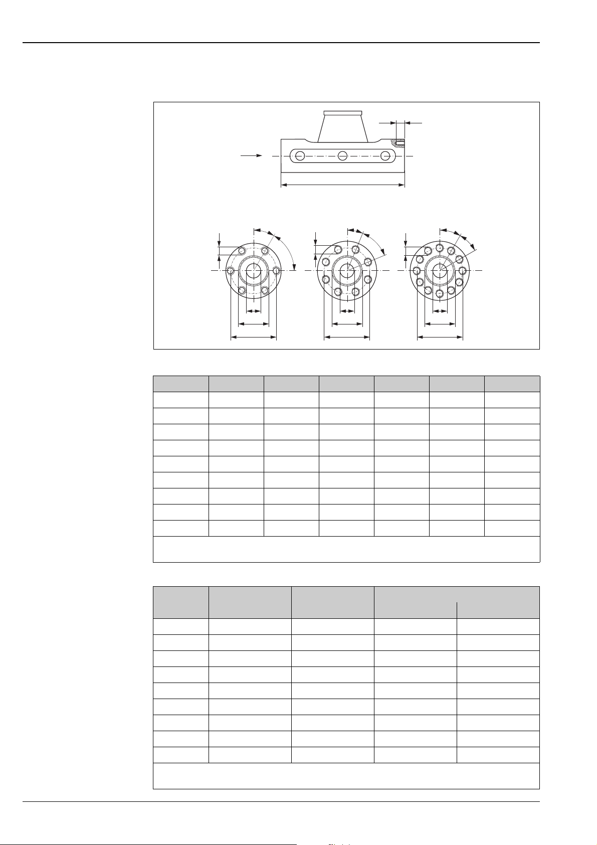
Promass M: without process connections
A
30°
M
DN DN DN
JJJ
KKK
60°
Proline Promass 84F, 84M
b
+1.5
L
–2.0
A DN40-50 A DN80A DN8-25
22,5°
45°
M
M
30°
30°
DN L J K M b
max.
8 256 27 54 6 × M 8 12 10
1)
8
256 27 546 × M 812 10
15 286 35 56 6 × M 8 12 10
15
1)
286 35 566 × M 812 10
25 310 40 62 6 × M 8 12 10
1)
25
310 40 626 × M 812 10
40 410 53 80 8 × M 10 15 13
50 544 73 94 8 × M 10 15 13
80 644 102 128 12 × M 12 18 15
All dimensions in [mm]; Further dimensions → Page 28 ff.
1)
High pressure version; permissible thread: A4 - 80; lubricant: Molykote P37
Tightening torque Lubricated thread O-ring
DN Nm YES/NO Thickness Inside Ø
8 30.0 NO 2.62 21.89
1)
8
19.3 YES 2.62 21.89
15 30.0 NO 2.62 29.82
15
1)
19.3 YES 2.62 29.82
25 30.0 NO 2.62 34.60
25
1)
19.3 YES 2.62 34.60
40 60.0 NO 2.62 47.30
50 60.0 YES 2.62 67.95
80 100.0 YES 3.53 94.84
All dimensions in [mm]; Further dimensions → Page 28 ff.
1)
High pressure version; permissible thread: A4 - 80; lubricant: Molykote P37
b
a0002535-en
min.
52 Endress+Hauser
Page 53
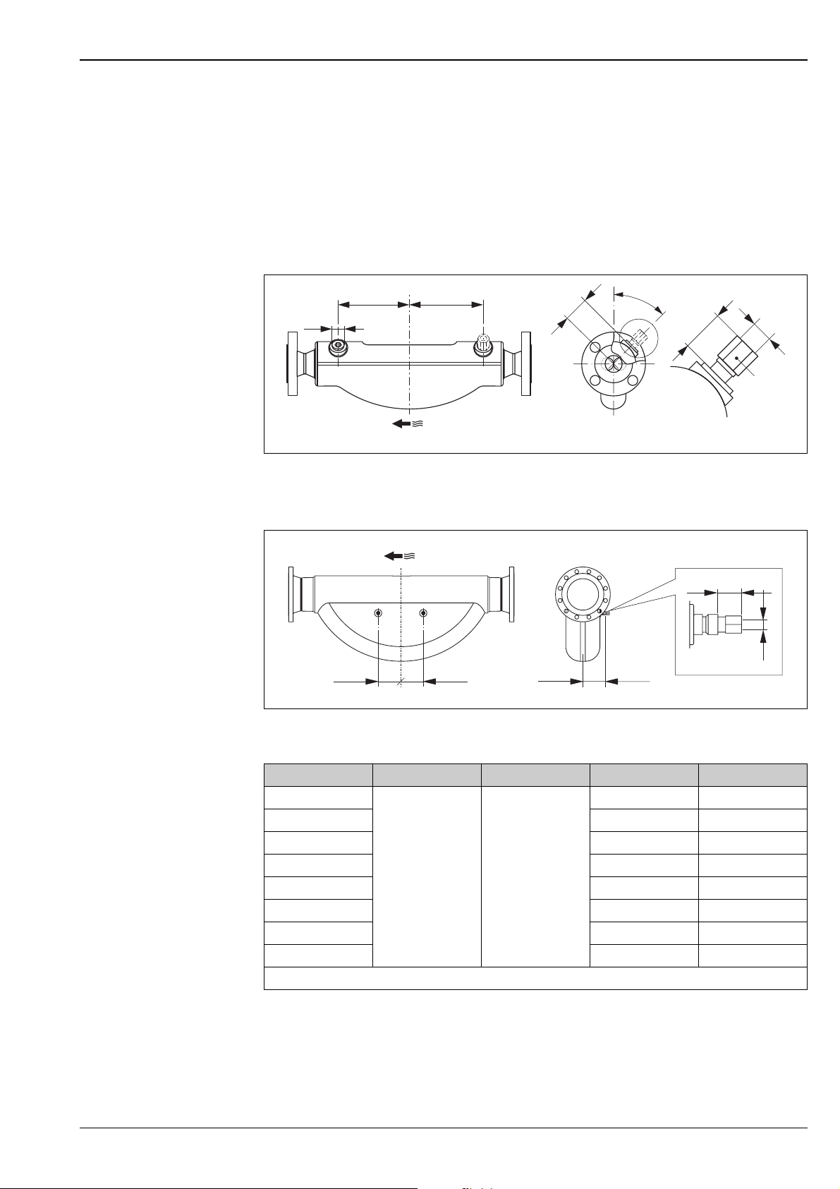
Proline Promass 84F, 84M
Purge connections / secondary containment monitoring
Caution!
"
• The secondary containment is filled with dry nitrogen (N
). Do not open the purge connections unless the
2
containment can be filled immediately with a dry inert gas. Use only low gauge pressure to purge.
Maximum pressure: 5 bar.
• Purge connections or secondary containment monitioring can not be combined with separately available
heating jacket.
Promass F: (not available for the Promass F high-temperature version)
4
LL
G
H
5
°
Z
Z
E
1
Promass F DN 8 to DN 150
1 = Flow direction
G
F
a0002537
LH
Promass F DN 250
DN F G H L
8
15 62 110
25 62 130
40 67 155
50 79 226
80 101 280
100 120 342
150 141 440
All dimensions in [mm]
E
G
L
a0009734
62 108
AF 1" ½"-NPT
Endress+Hauser 53
Page 54
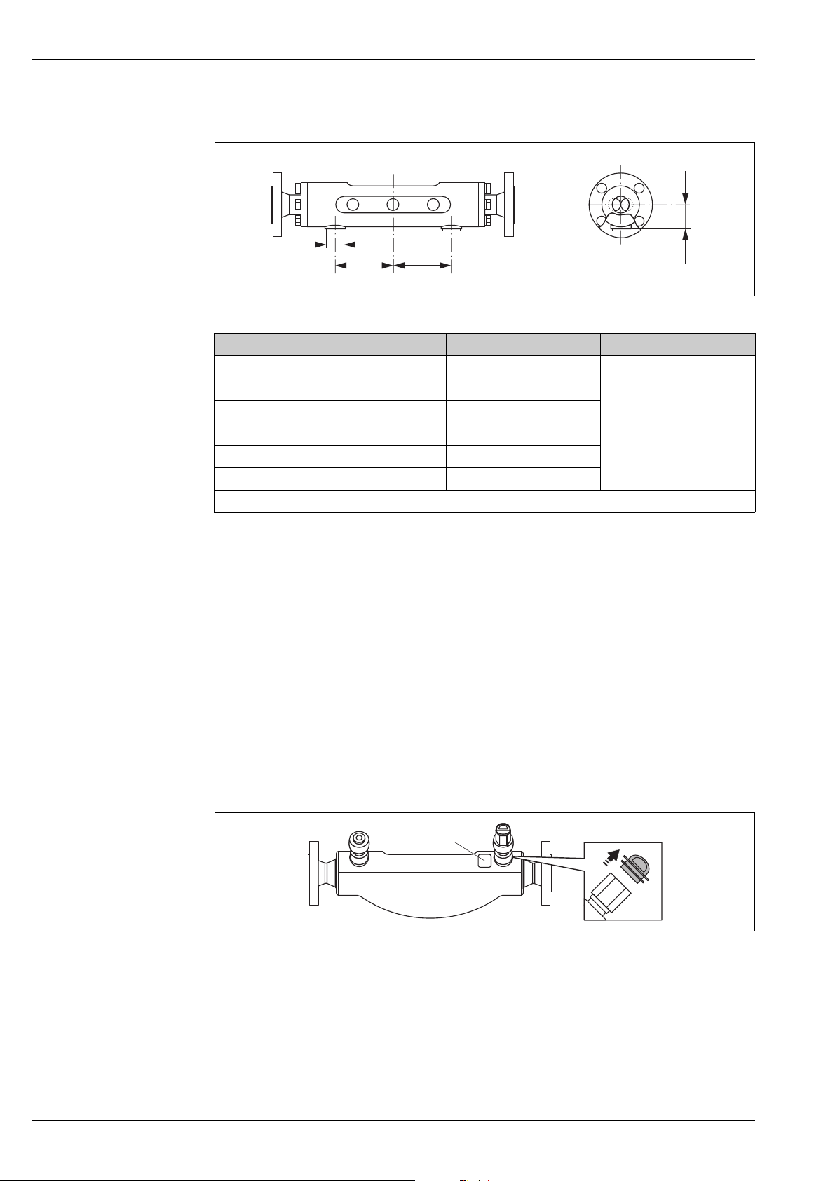
Proline Promass 84F, 84M
Promass M:
G
LL
DN L H G
885 44.0
15 100 46.5
25 110 50.0
40 155 59.0
50 210 67.5
80 210 81.5
All dimensions in [mm]
H
a0002536
½"-NPT
#
"
!
Rupture disk
Sensor housings with integrated rupture disks are optionally available.
Warning!
• Make sure that the function and operation of the rupture disk is not impeded through the installation.
Triggering overpressure in the housing as stated on the indication label. Take adequate precautions to ensure
that no damage occurs, and risk to human life is ruled out, if the rupture disk is triggered.
Rupture disk: Burst pressure 10 to 15 bar.
• Please note that the housing can no longer assume a secondary containment function if a rupture disk is used.
• It is not permitted to open the connections or remove the rupture disk.
Caution!
• Rupture disks can not be combined with separately available heation jacket.
• The existing connection nozzles are not designed for a rinse or pressure monitoring function.
Note!
• Before commissioning, please remove the transport protection of the rupture disk.
• Please note the indication labels.
1
2
3
A0008361
Promass F DN 8 to DN 150
1 = Indication label for the rupture disk, 2 = Transport protection, 3 = ½" NPT internal screw thread with 1" width across
flats
54 Endress+Hauser
Page 55
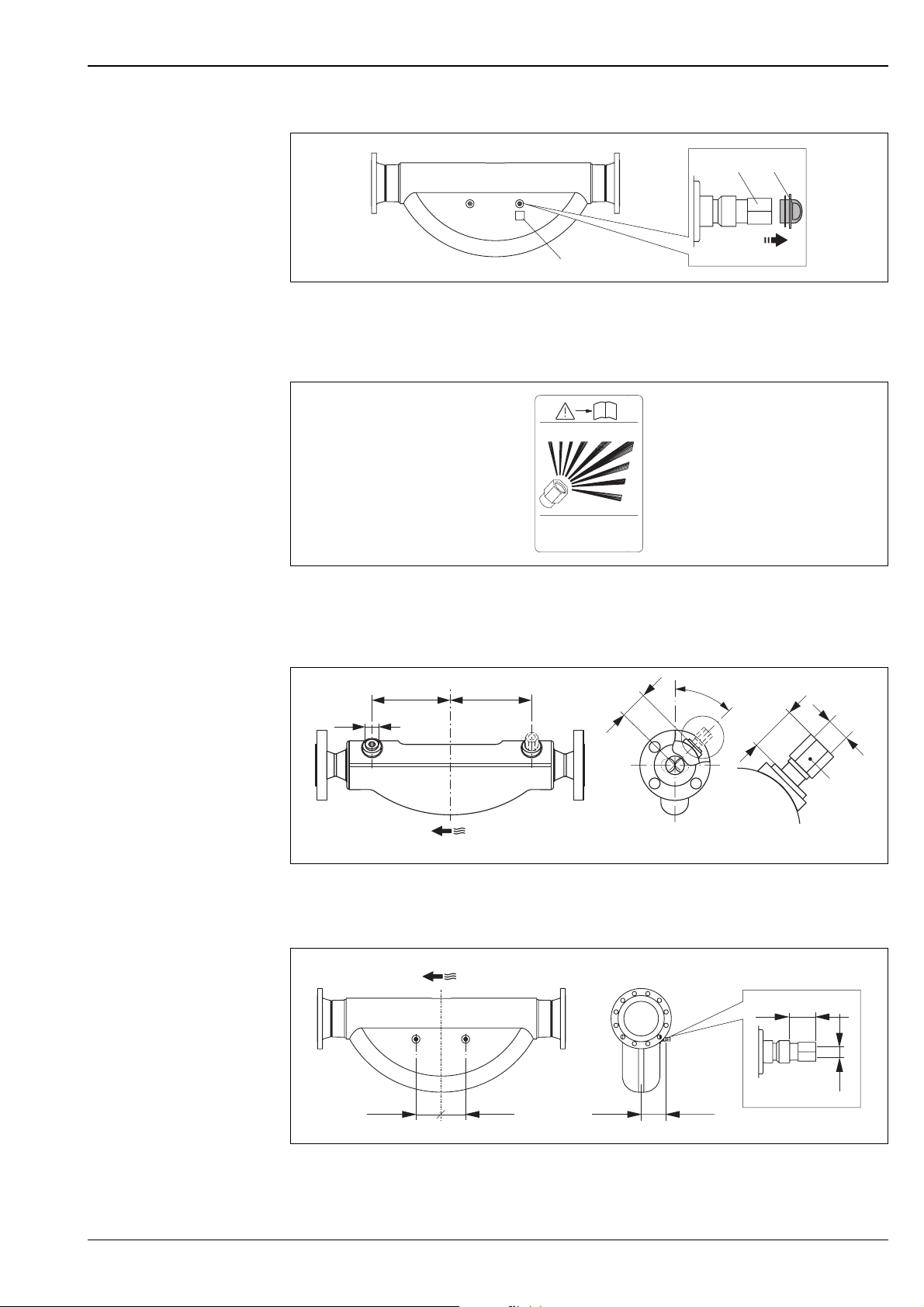
Proline Promass 84F, 84M
3
2
1
A0009733
Promass F DN 250
1 = Indication label for the rupture disk, 2 = Transport protection, 3 = ½" NPT internal screw thread with 1" width across
flats
i
RUPTURE DISK
12,5 BAR +/-10%@80°C
Indication label for the rupture disk
Promass F: (not available for the Promass F high-temperature version)
LL
G
H
1
Promass F DN 8 to DN 150
1 = Flow direction
A0008788
4
5
°
Z
Z
E
G
F
a0002537
E
G
LH
L
a0009734
Promass F DN 250
Endress+Hauser 55
Page 56
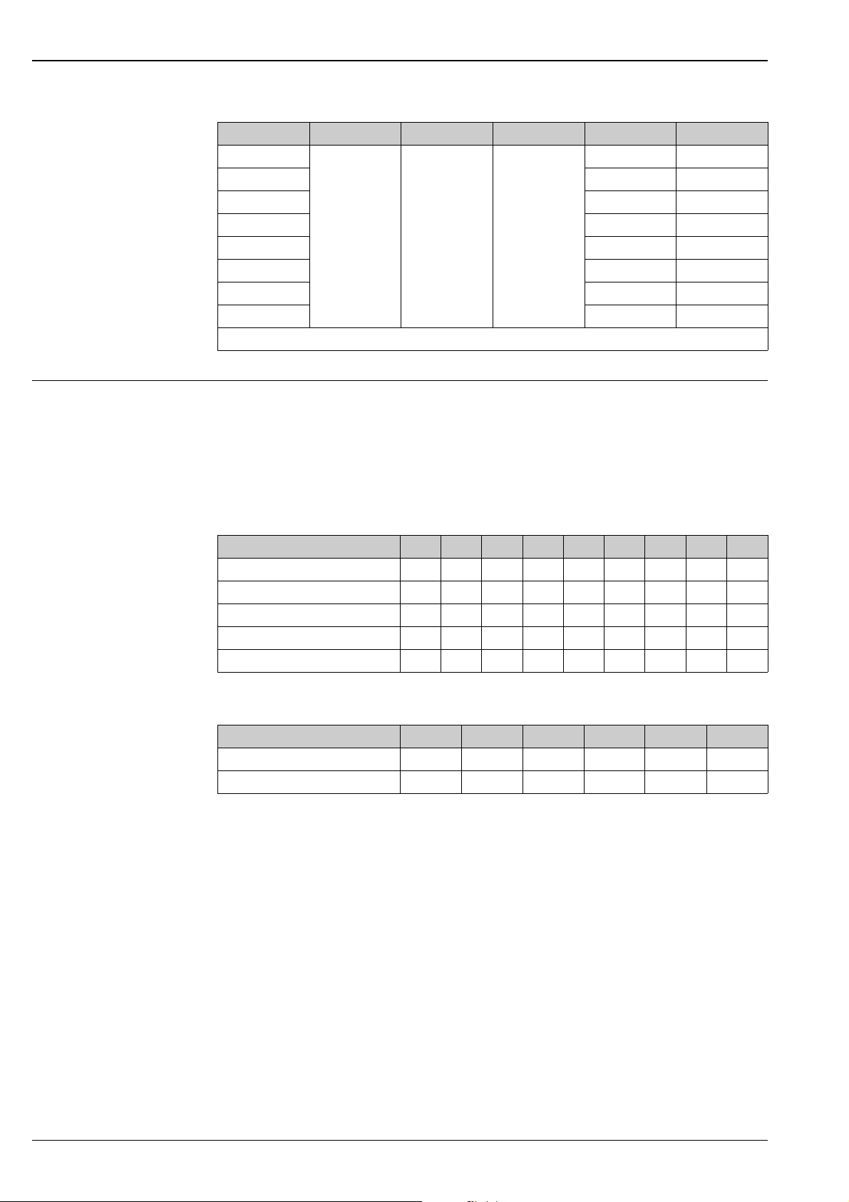
DN E F G H L
8
15 62 110
25 62 130
40 67 155
50 79 226
80 101 280
100 120 342
150 141 440
All dimensions in [mm]
approx. 42 AF 1" ½"-NPT
Weight • Compact version: see table below
• Remote version
– Sensor: see table below
– Wall-mount housing: 5 kg
Proline Promass 84F, 84M
62 108
Weight data in [kg].
All values (weight) refer to devices with EN/DIN PN 40 flanges.
Promass F / DN 8 15 25 40 50 80 100 150 250 *
Compact version 11121419305596154400
Compact version High temperature −−14,7 − 30,7 55,7 −−−
Compact version Ex d 202123283964105163409
Remote version 9 10 12 17 28 53 94 152 398
Remote version High temperature −−13,5 − 29,5 54,5 −−−
* With 10" according to ASME B16.5 Cl 300 flanges
Promass M / DN 8 15 25 40 50 80
Compact version 111215244167
Remote version 9 10 13 22 39 65
56 Endress+Hauser
Page 57

Proline Promass 84F, 84M
Material Transmitter housing:
• Compact housing:
– stainless steel 1.4301/304
– powder coated die-cast aluminium
– Compact housing Ex d: stainless steel CF3M
• Compact housing:
– Wall-mount housing: powder coated die-cast aluminium
– Remote field housing: powder-coated die-cast aluminium
Connection housing, sensor (remote version):
• Stainless steel 1.4301/304 (standard)
• powder coated die-cast aluminium (high-temperature version and version for heating)
Sensor housing / containment:
• Promass F: Acid- and alkali-resistant outer surface
– stainless steel 1.4301/1.4307/304L
• Promass M: Acid- and alkali-resistant outer surface
– DN 8 to 50: steel, chemically nickel-plated
– DN 80: stainless steel
Measuring tube(s):
•Promass F
– DN 8 to 100: stainless steel 1.4539/904L
– DN 150: stainless steel 1.4404/316L
– DN 250: stainless steel 1.4404/316L; manifold: CF3M
– DN 8 to 150: Alloy C-22 2.4602/N 06022
• Promass F (High temperature version)
– DN 8, 50, 80: Alloy C-22 2.4602/N 06022
•Promass M
– DN 8 to 50: titanium grade
– DN 80: titanium grade 2
• Promass M (High pressure version)
– Titanium grade 9
Endress+Hauser 57
Page 58
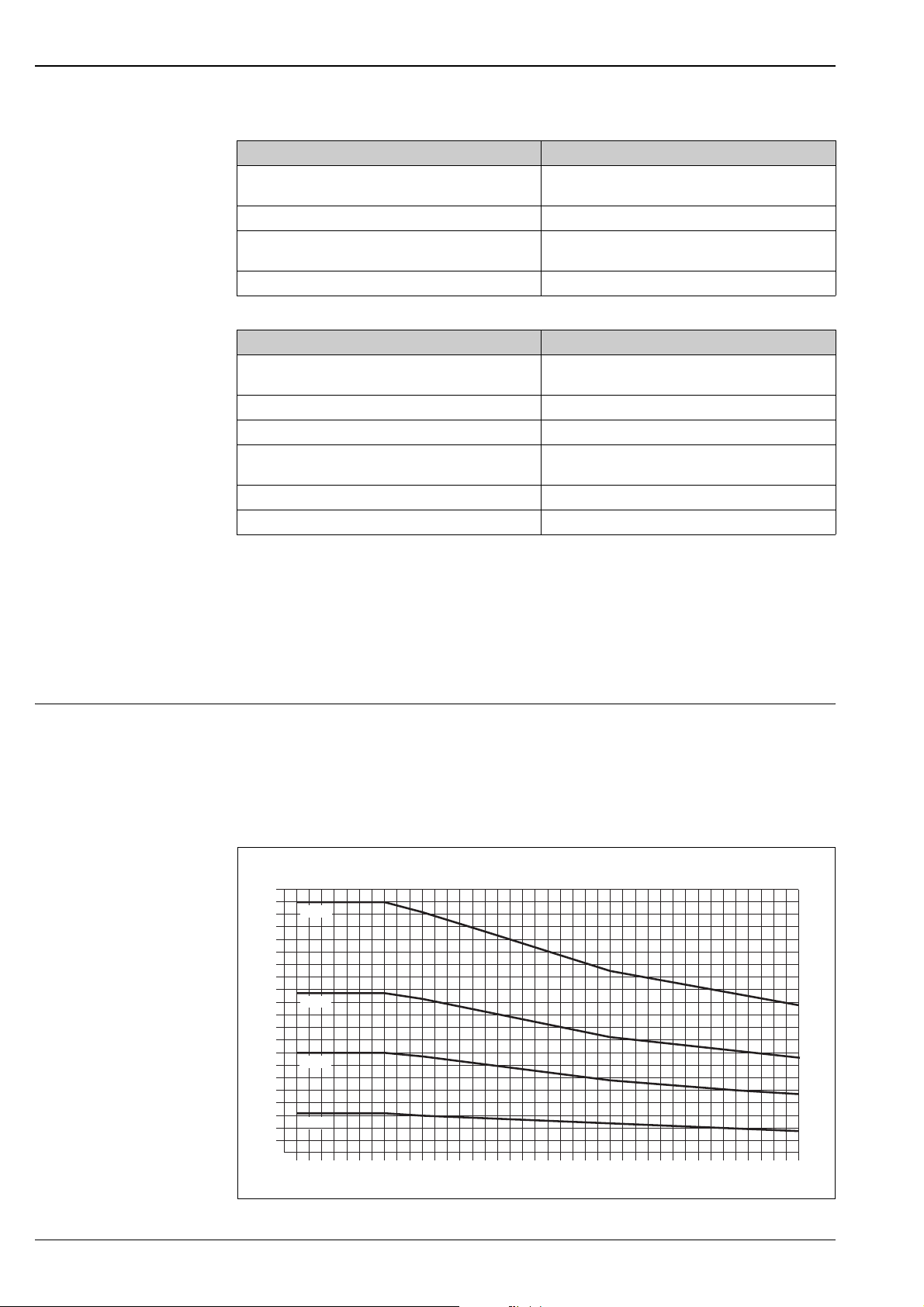
Process connections
Process connections Promass F Material
Flange according to EN 1092-1 (DIN 2501) / according to
ASME B16.5 / JIS B2220
Flange DIN 11864-2 Form A (flat flange with groove) Stainless steel 1.4404/316L
Threaded hygienic connection DIN 11851 / SMS 1145 /
ISO 2853 / DIN 11864-1
Tri-Clamp (OD-Tubes) Stainless steel 1.4404/316L
Process connections Promass M Material
Flange according to EN 1092-1 (DIN 2501) / according to
ASME B16.5 / JIS B2220
Flange DIN 11864-2 Form A (flat flange with groove) Stainless steel 1.4404/316L
PVDF-connections DIN / ASME B16.5 / JIS PVDF
Threaded hygienic connection DIN 11851 / SMS 1145 /
ISO 2853 / DIN 11864-1
Connector (High pressure version) Stainless steel 1.4404/316L
Coupling (High pressure version) Stainless steel 1.4401/316
Alloy C-22 2.4602/N 06022, Stainless steel 1.4404/316L
Stainless steel 1.4404/316L
Stainless steel 1.4404/316L, Titan Grade 2
Stainless steel 1.4404/316L
Seals:
• Promass F: welded process connections without internal seals
•Promass M
–Viton
– EPDM
– Silikon
– Kalrez 6375
– FEP sheathing (not for gas applications)
Proline Promass 84F, 84M
Material load curves
#
Warning!
The following material loade curves refer to the entire sensor and not just the process conection.
Promass F with flange connection according to EN 1092-1 (DIN 2501)
Flange material: 1.4404/316L, Alloy C-22
[bar]
100
PN100
90
80
70
PN63
60
50
40
PN40
30
20
PN16
10
0
-60
-40
-20
020
40 60 80 100 120 140
160
180
200
220 240 260 280 300 320 340
[°C]
a0004654-en
The values for the temperature range from 200 °C to 350 °C are exclusively valid for the high-temperature version.
58 Endress+Hauser
Page 59
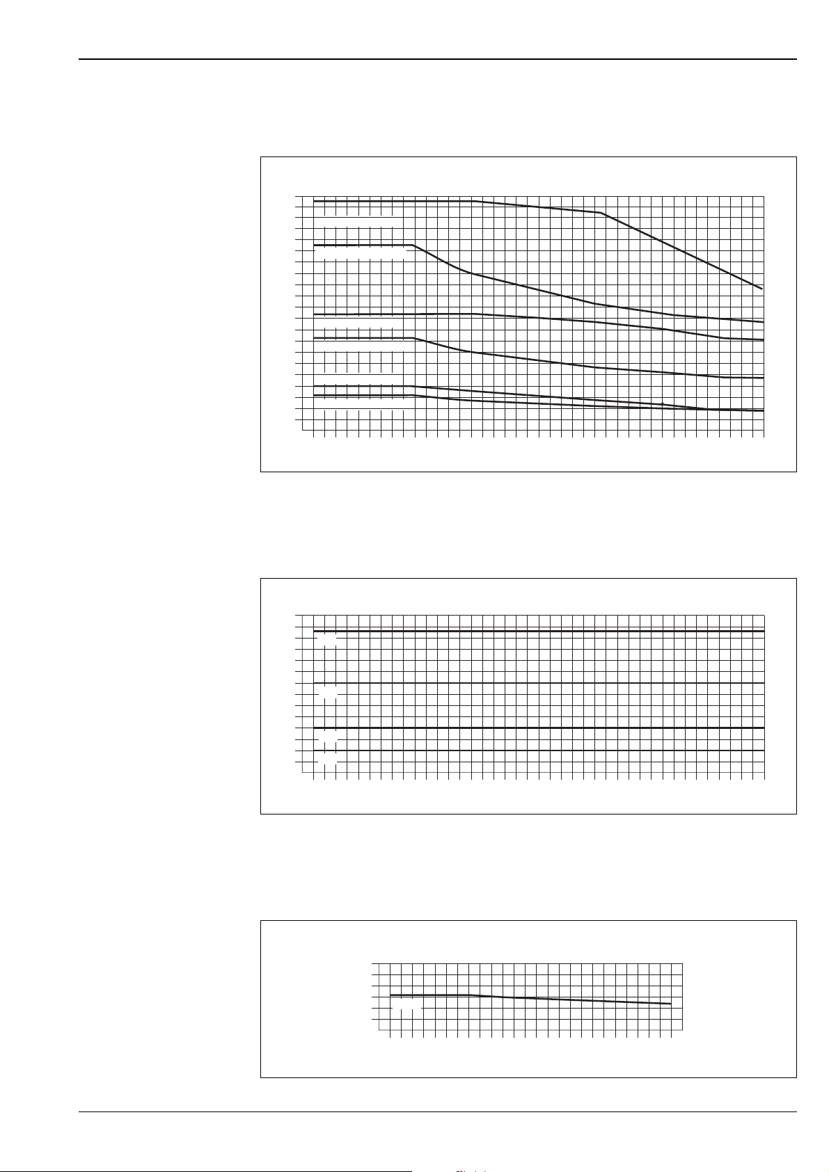
Proline Promass 84F, 84M
Promass F with flange connection according to ASME B16.5
Flange material: 1.4404/316L, Alloy C-22
[bar]
100
AlloyC-22,Class 600
90
80
1.4404/316L,Class 600
70
60
50
AlloyC-22,Class 300
40
1.4404/316L,Class 300
30
AlloyC-22,Class 150
20
1.4404/316L,Class 150
10
0
-60
-40
-20
020
40 60 80 100 120 140
160
180
200
220 240 260 280 300 320 340
[°C]
The values for the temperature range from 200 °C to 350 °C are exclusively valid for the high-temperature version.
Promass F with flange connection to JIS B2220
Flange material: 1.4404/316L, Alloy C-22
[bar]
70
60
63K
50
40
40K
30
20
20K
10
10K
0
-60
-40
-20
020
40 60 80 100 120 140
160
180
200
220 240 260 280 300 320 340
The values for the temperature range from 200 °C to 350 °C are exclusively valid for the high-temperature version.
Promass F with threaded hygienic connection to DIN 11851 / SMS 1145
Connection material: 1.4404/316L
a0004655-en
[°C]
a0004656-en
[bar]
30
20
PN16
10
0
-60
-40
-20
020
40 60 80 100 120 140
160
180
200
[°C]
a0004657-en
Endress+Hauser 59
Page 60
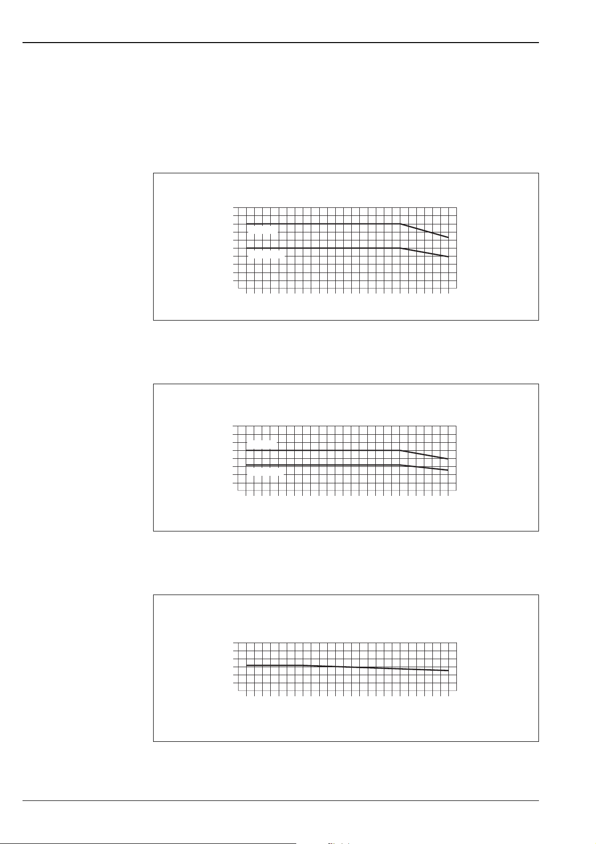
Proline Promass 84F, 84M
Promass F with Tri-Clamp process connection
The Clamp connections (e.g. Tri-Clamp ISO2852, DIN32676) are suited up to a maximum pressure of 16 bar.
As these operating limits also depend on the clamp and the seal used, their specifications have to be observed.
The clamp and the seal are not included in the scope of supply
Promass F with threaded hygienic connection to DIN 11864-1
Connection material: 1.4404/316L
[bar]
50
40
DN 8...40
30
DN 50...100
20
10
0
-60
-40
-20
020
40 60 80 100 120 140
160
180
200
[°C]
a0004658-en
Promass F with flange connection to DIN 11864-2 Form A (flat flange with groove)
Flange material: 1.4404/316L
[bar]
40
30
DN 8...40
20
DN 50...100
10
0
-60
-40
-20
020
40 60 80 100 120 140
160
180
200
[°C]
Promass F with threaded hygienic connection to ISO 2853
Connection material: 1.4404/316L
[bar]
30
20
10
0
-60
-40
-20
020
40 60 80 100 120 140
160
180
200
[°C]
a0004659-en
a0004660-en
60 Endress+Hauser
Page 61
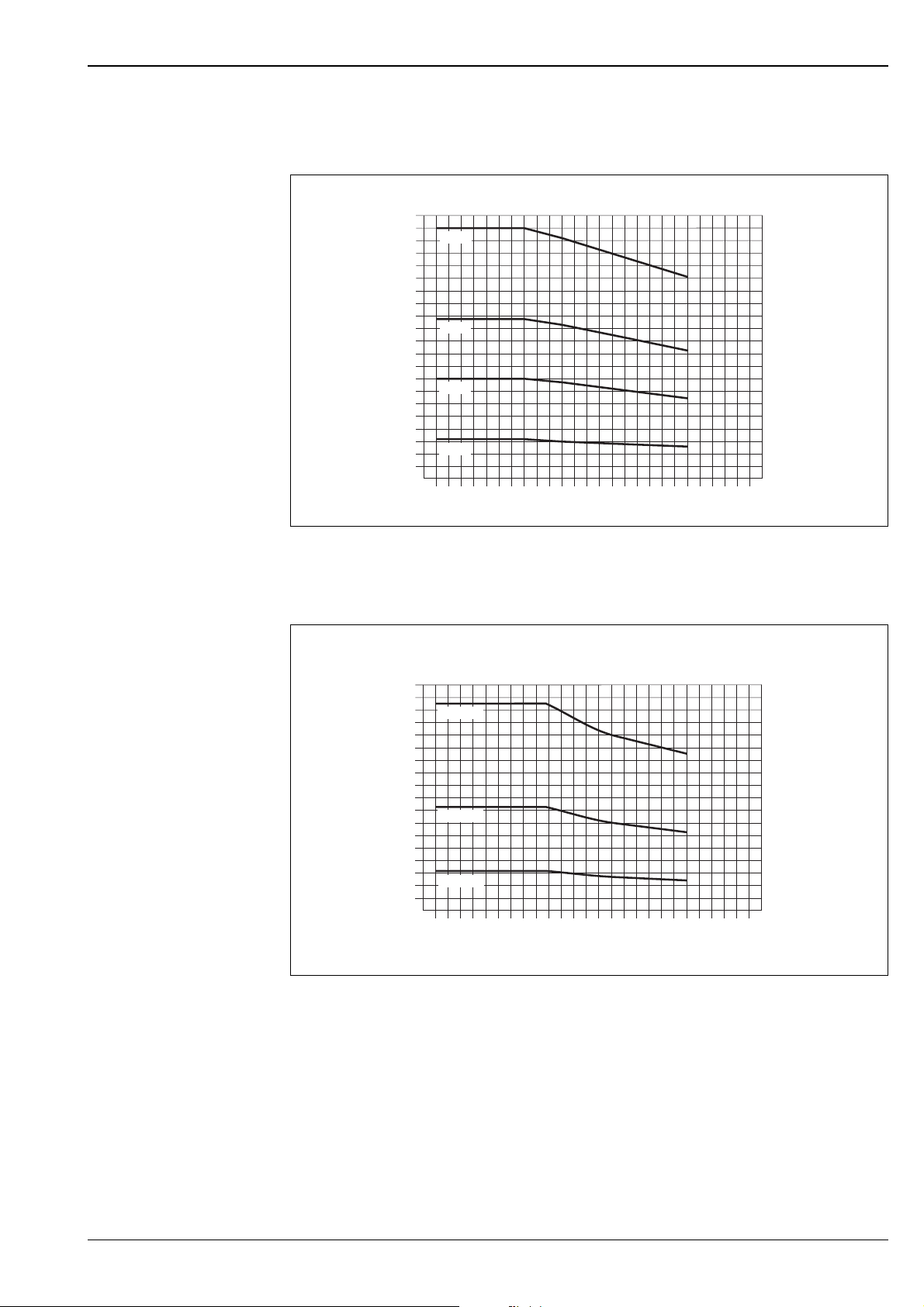
Proline Promass 84F, 84M
Promass M with flange connection according to EN 1092-1 (DIN 2501)
Flange material: 1.4404/316L, titanium grade 2
[bar]
100
PN100
90
80
70
PN63
60
50
40
PN40
30
20
PN16
10
0
-60
-40
-20
020
40 60 80 100 120 140
Promass M with flange connection according to ASME B16.5
Flange material: 1.4404/316L, titanium grade 2
[bar]
90
80
Class 600
70
60
50
40
Class 300
30
20
Class 150
10
0
-60
-40
-20
020
40 60 80 100 120 140
160
160
180
180
200
200
[°C]
a0003293-en
[°C]
a0003297-en
Endress+Hauser 61
Page 62
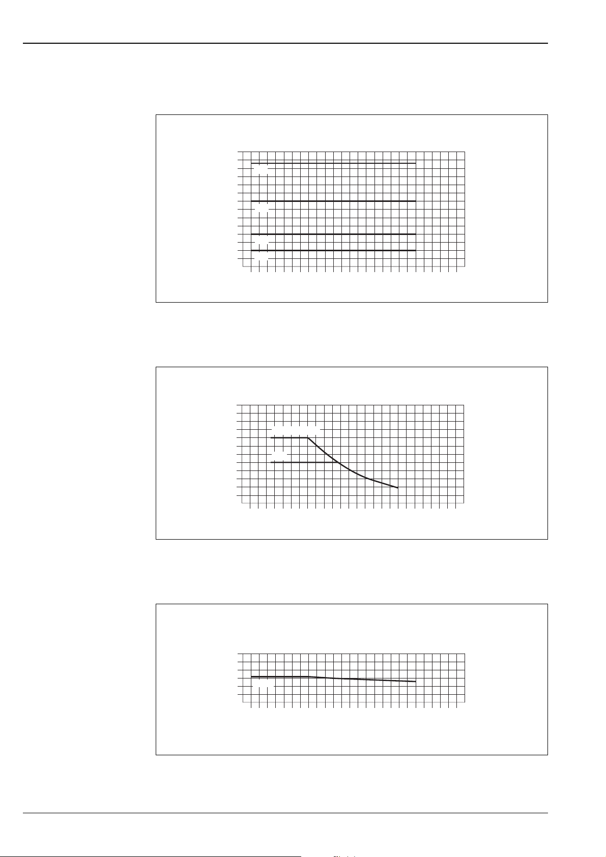
Promass M with flange connection to JIS B2220
Flange material: 1.4404/316L, titanium grade 2
[bar]
70
60
63K
50
40
40K
30
20
20K
10
10K
0
-60
-40
-20
020
40 60 80 100 120 140
Proline Promass 84F, 84M
160
180
200
[°C]
a0003304-en
Promass M with PVDF flange connection (to DIN 2501, according to ASME B16.5, JIS B2220)
Flange material: PVDF
[bar]
24
20
16
12
8
4
0
-60 -40 -20 0 20 40 60 80 100 120 140 180 200160
PN16/Class150
10K
[°C]
Promass M with threaded hygienic connection to DIN 11851 / SMS 1145
Connection material: 1.4404/316L
a0004661-en
[bar]
30
20
PN16
10
0
-60 -40 -20 0 20 40 60 80 100 120 140 180 200160
[°C]
a0003305-en
62 Endress+Hauser
Page 63
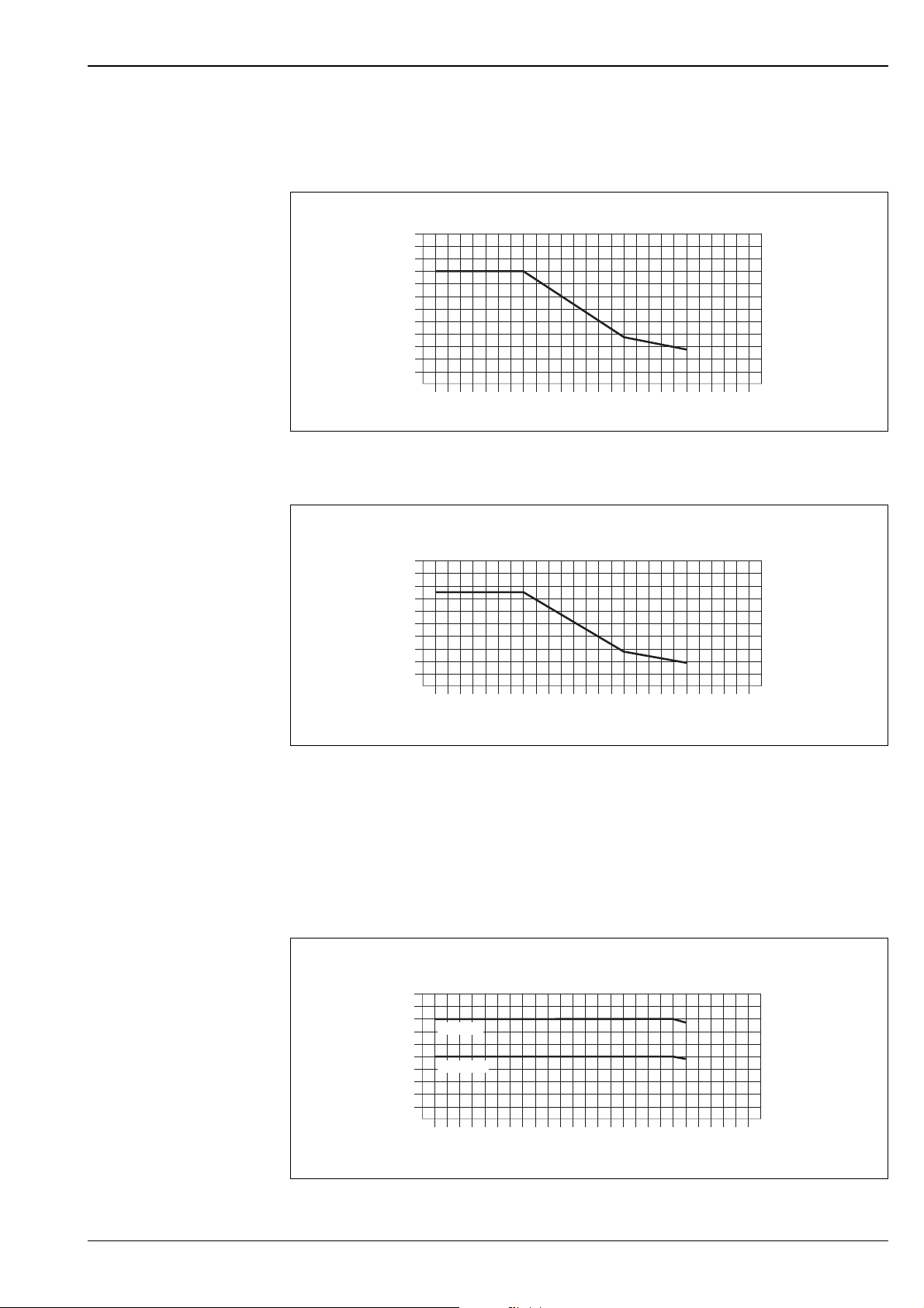
Proline Promass 84F, 84M
Promass M with process connections for high pressure version
Connector material: 1.4404/316L
Material of thread connections (G 3/8", VCO with ½" SWAGELOK, NPT 3/8"): 14401/316
[bar]
380
360
340
320
300
280
260
-60
-40
-20
020
40 60 80 100 120 140
160
180
200
[°C]
Material of thread connections (NPT ½"): 1.4401/316
a0004662-en
[bar]
340
320
300
280
260
240
-60
-40
-20
020
40 60 80 100 120 140
160
180
200
[°C]
a0004663-en
Promass M with Tri-Clamp process connection
The Clamp connections (e.g. Tri-Clamp ISO 2852, DIN 32676) are suited up to a maximum pressure of 16 bar.
As these operating limits also depend on the clamp and the seal used, their specifications have to be observed.
The clamp and the seal are not included in the scope of supply.
Promass M with threaded hygienic connection to DIN 11864-1
Connection material: 1.4404/316L
[bar]
50
40
DN 8...40
30
DN 50...80
20
10
0
-60
-40
-20
020
40 60 80 100 120 140
160
180
200
[°C]
a0004664-en
Endress+Hauser 63
Page 64
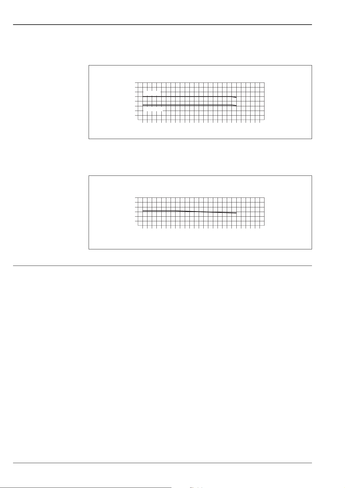
Proline Promass 84F, 84M
Promass M with flange connection to DIN 11864-2 Form A (flat flange with groove)
Flange material: 1.4404/316L
[bar]
40
30
DN 8...40
20
DN 50...80
10
0
-60
-40
-20
020
40 60 80 100 120 140
Promass M with threaded hygienic connection to ISO 2853
Connection material: 1.4404/316L
160
180
200
[°C]
a0004665-en
[bar]
30
20
10
0
-60 -40 -20 0 20 40 60 80 100 120 140 180 200160
Process connections Promass F (welded process connections)
• Flanges
– according to EN 1092-1 (DIN 2501)
– according to ASME B16.5
– JIS B2220
• Sanitary connections
–Tri-Clamp
– threaded hygienic connections (DIN 11851, SMS 1145, ISO 2853, DIN 11864-1)
– flange DIN 11864-2 Form A (flat flange with groove)
Promass M (threaded process connections)
• Flanges
– according to EN 1092-1 (DIN 2501)
– according to ASME B16.5
– JIS B2220
• Sanitary connections
–Tri-Clamp
– threaded hygienic connections (DIN 11851, SMS 1145, ISO 2853, DIN 11864-1)
– flange DIN 11864-2 Form A (flat flange with groove)
[°C]
a0003308-en
Promass M (high pressure version)
• Thread connections
– G 3/8"-coupling
– ½"-NPT--coupling
– 3/8"-NPT-coupling
– ½"-SWAGELOK-coupling
– connector with 7/8-14UNF internal thread
64 Endress+Hauser
Page 65
Proline Promass 84F, 84M
Human interface
Display elements • Liquid crystal display: illuminated, four lines with 16 characters per line
• Selectable display of different measured values and status variables
• At ambient temperatures below –20 °C the readability of the display may be impaired.
Unified control concept for both types of transmitter:
Language groups Language groups available for operation in different countries:
Remote operation
• Local operation with three optical sensors (S, O, F)
• Application specific Quick Setup menus for straightforward commissioning
• Western Europe and America (WEA):
English, German, Spanish, Italian, French, Dutch and Portuguese
• Eastern Europe and Scandinavia (EES):
English, Russian, Polish, Norwegian, Finnish, Swedish and Czech
• South and east Asia (SEA):
English, Japanese, Indonesian
• China (CIN):
English, Chinese
You can change the language group via the operating program "FieldCare"
Operation via HART
Certificates and approvals
CE mark The measuring system is in conformity with the statutory requirements of the EC Directives.
Endress+Hauser confirms successful testing of the device by affixing to it the CE mark.
Ex approval Information about currently available Ex versions (ATEX, FM, CSA, IECEx, NEPSI) can be supplied by your
Endress+Hauser Sales Centre on request. All explosion protection data are given in a separate documentation
which is available upon request.
C-tick mark The measuring system meets the EMC requirements of the Australian Communication and
Media Authority (ACMA).
Sanitary compatibility • 3A approval
•EHEDG tested
MODBUS RS485 The measuring device meets all the requirements of the MODBUS/TCP conformity and integration test and
has the "MODBUS/TCP Conformance Test Policy, Version 2.0". The measuring device has successfully passed
all the test procedures carried out and is certified by the "MODBUS/TCP Conformance Test Laboratory" of the
University of Michigan.
Endress+Hauser 65
Page 66

Proline Promass 84F, 84M
Other standards and guidelines
Pressure device approval Flowmeters with a nominal diameter smaller or equal DN 25 are covered by Art. 3 (3) of the European
Measuring instrument approval
!
• EN 60529
Degrees of protection by housing (IP code)
• EN 61010
Protection Measures for Electrical Equipment for Measurement, Control, Regulation and
Laboratory Procedures)
• ICE/EN 61326
"Emission in accordance with requirements for Class A" Electromagnetic compatibility (EMC- requirements)
•NAMUR NE 21
Electromagnetic compatibility (EMC) of industrial process and laboratory control equipment
•NAMUR NE 43
Standardisation of the signal level for the breakdown information of digital transmitters with analogue
output signal.
•NAMUR NE 53
Software of field devices and signal-processing devices with digital electronics
directive 97/23/EC (Pressure Equipment Directive) and are designed according to sound engineer practice.
For larger nominal diameters, optional approvals according to Cat. II/III are available when required
(depends on fluid and process pressure).
Optionally flowmeters in accordance to the guidelines AD 2000 are available on request.
This flowmeter which is a suitable component in measuring systems subject to legal metrology controls in
accordance with Annex MI-005 of the European Measuring Instruments Directive 2004/22/EC (MID).
This flowmeter is qualified to OIML R117-1 and has an MID Evaluation Certificate
compliance with the essiential requirements of the Measuring Instruments Directive.
Note!
According to the Measuring Instruments Directive, however, only the complete measuring system is licensable,
covered by an EC type-examination certificate and bears conformity marking.
(1)
The Evaluation Certificate results from the WELMEC (cooperation between the legal metrology services of
the member states of the European Union and EFTA) towards voluntary modular approval for measuring
systems in accordance with Annex MI-005 (measuring systems for the continuous and dynamic measurement
of quantities of liquids other than water) of the Measuring Instruments Directive 2004/22/EC.
(1)
which confirms
Approval for custody transfer Promass 84 is a flowmeter suitable for custody transfer measurement for liquids (other than water) and
for fuel gases under high pressure (> 100 bar). The requirements of the following test centres are taken into
consideration:
•PTB, Germany
• NMi, The Netherlands
• METAS, Switzerland
•BEV, Austria
• NTEP, USA
• MC, Canada
Information on custody transfer measurement see Page 25 ("Custody transfer measurement" Section)
66 Endress+Hauser
Page 67
Proline Promass 84F, 84M
Suitability for custody transfer measurement
PTB / NMi / METAS / BEV approval
PTB / NMi / METAS / BEV approval for determining the mass and volume of liquids, other than water, and
of fuel gases. The device is qualified to OIML R117-1.
Promass DN OIML R117-1/MID Evaluation Certificate (Europe)
[mm] [inch] Mass Volume Density
F 8 to 250 3/8" to 10" YES YES YES
M 8 to 80 3/8" to 3" NO NO NO
Promass DN PTB / METAS /BEV approval for
For liquids other than water High-pressure gas
[mm] Mass Volume Density (CNG) Mass
F 8 to 250 YES YES YES NO
M8 to 50YES NO NO NO
M 80 YES YES YES NO
M 8 to 40 NO NO NO YES
M (high pressure) 8 to 25 NO NO NO YES
Promass DN NMi approval for
For liquids other than water High-pressure gas
[mm] Mass Volume Density (CNG) Mass
F 8 to 250 YES YES YES NO
M8 to 80YES NO NO NO
M 8 to 40 NO NO NO YES
M (high pressure) 8 to 25 NO NO NO YES
NTEP approval
The measuring instrument is qualified in accordance with the National Type Evaluation Program (NTEP)
Handbook 44 ("Specifications and Tolerances and other Technical Requirements for Weighing and Measuring
Devices").
Promass DN NTEP approval for
For liquids other than water High-pressure gas
[mm] Mass Volume (CNG) Mass
F 15 to 150 YES YES NO
M 15 to 80 YES YES NO
M (high pressure) 15 to 25 NO NO YES
MC approval
The measuring instrument is qualified in accordance with "The Draft Ministerial Specifications Mass Flow Meters" (1993-09-21).
Promass DN MC approval for
For liquids other than water
[mm] Mass Volume
F8 to 150 YES YES
M8 to 80 YES NO
Ordering information
The Endress+Hauser service organisation can provide detailed ordering information and information on the
order codes on request.
Endress+Hauser 67
Page 68

Proline Promass 84F, 84M
Accessories
Various accessories, which can be ordered separately from Endress+Hauser, are available for the transmitter
and the sensor. The Endress+Hauser service organisation can provide detailed information on the order codes
of your choice.
Documentation
• Flow measuring technology (FA005D/06/en)
• Technical Information Promass 84A (TI068D/06/en)
• Operating Instructions Promass 84 (BA109D/06/en)
• Description of Device Functions Promass 84 (BA110D/06/en)
• Operating Instructions Promass 84 MODBUS RS485 (BA129D/06/en)
• Description of Device Functions Promass 84 MODBUS RS485 (BA130D/06/en)
• Supplementary documentation on Ex-ratings: ATEX, FM, CSA, IECEx, NEPSI
Registered trademarks
KALREZ® and VITON
Registered trademarks of E.I. Du Pont de Nemours & Co., Wilmington, USA
TRI-CLAMP
Registered trademark of Ladish & Co., Inc., Kenosha, USA
SWAGELOK
Registered trademark of Swagelok & Co., Solon, USA
HART
Registered trademark of HART Communication Foundation, Austin, USA
HistoROM™, S-DAT®, T-DAT™, FieldCare®, Fieldcheck®, Applicator
Registered or registration-pending trademarks of Endress+Hauser Flowtec AG, Reinach, CH
®
®
®
®
®
68 Endress+Hauser
Page 69

Proline Promass 84F, 84M
Endress+Hauser 69
Page 70

Proline Promass 84F, 84M
70 Endress+Hauser
Page 71

Proline Promass 84F, 84M
Endress+Hauser 71
Page 72
Instruments International
Endress+Hauser
Instruments International AG
Kaegenstrasse 2
4153 Reinach
Switzerland
Tel. +41 61 715 81 00
Fax +41 61 715 25 00
www.endress.com
[email protected]
TI067D/06/en/07.08
71076893
FM+SGML6.0 ProMoD
 Loading...