

Page 1
KA00024D/06/EN/15.12
71197503
Brief Operating Instructions
Proline Promass 83
Coriolis Mass Flow Measuring System
These Brief Operating Instructions are not intended to replace the
Operating Instructions provided in the scope of supply.
Detailed information is provided in the Operating Instructions and
the additional documentation on the CD-ROM supplied.
The complete device documentation consists of:
• These Brief Operating Instructions
• Depending on the device version:
– Operating Instructions and the Description of Device Functions
– Approvals and safety certificates
– Safety instructions in accordance with the approvals for
the device (e.g. explosion protection, pressure equipment
directive, etc.)
– Additional device-specific information
Page 2

Proline Promass 83
2 Endress+Hauser
Table of contents
1 Safety instructions . . . . . . . . . . . . . . . . . . . . . . . . . . . . . . . . . . . . . 3
1.1 Designated use . . . . . . . . . . . . . . . . . . . . . . . . . . . . . . . . . . . . . . . . . . . . . . . . . . . . . . . 3
1.2 Installation, commissioning and operation . . . . . . . . . . . . . . . . . . . . . . . . . . . . . . . . . . . 3
1.3 Operational safety . . . . . . . . . . . . . . . . . . . . . . . . . . . . . . . . . . . . . . . . . . . . . . . . . . . . . 3
1.4 Safety conventions . . . . . . . . . . . . . . . . . . . . . . . . . . . . . . . . . . . . . . . . . . . . . . . . . . . . 5
2 Installation . . . . . . . . . . . . . . . . . . . . . . . . . . . . . . . . . . . . . . . . . . 6
2.1 Transporting to the measuring point . . . . . . . . . . . . . . . . . . . . . . . . . . . . . . . . . . . . . . . 6
2.2 Installation conditions . . . . . . . . . . . . . . . . . . . . . . . . . . . . . . . . . . . . . . . . . . . . . . . . . . 7
2.3 Post-installation . . . . . . . . . . . . . . . . . . . . . . . . . . . . . . . . . . . . . . . . . . . . . . . . . . . . . 10
2.4 Post-installation check . . . . . . . . . . . . . . . . . . . . . . . . . . . . . . . . . . . . . . . . . . . . . . . . . 13
3 Wiring. . . . . . . . . . . . . . . . . . . . . . . . . . . . . . . . . . . . . . . . . . . . . 14
3.1 Connecting the various housing types . . . . . . . . . . . . . . . . . . . . . . . . . . . . . . . . . . . . . 15
3.2 Degree of protection . . . . . . . . . . . . . . . . . . . . . . . . . . . . . . . . . . . . . . . . . . . . . . . . . . 16
3.3 Post-connection check . . . . . . . . . . . . . . . . . . . . . . . . . . . . . . . . . . . . . . . . . . . . . . . . 16
4 Hardware settings . . . . . . . . . . . . . . . . . . . . . . . . . . . . . . . . . . . . 17
4.1 Device address PROFIBUS DP/PA, Modbus RS485 . . . . . . . . . . . . . . . . . . . . . . . . . . . 17
4.2 Device address EtherNet/IP network . . . . . . . . . . . . . . . . . . . . . . . . . . . . . . . . . . . . . 19
4.3 Terminating resistors . . . . . . . . . . . . . . . . . . . . . . . . . . . . . . . . . . . . . . . . . . . . . . . . . . 20
5 Commissioning . . . . . . . . . . . . . . . . . . . . . . . . . . . . . . . . . . . . . . 21
5.1 Switching on the measuring device . . . . . . . . . . . . . . . . . . . . . . . . . . . . . . . . . . . . . . 21
5.2 Operation . . . . . . . . . . . . . . . . . . . . . . . . . . . . . . . . . . . . . . . . . . . . . . . . . . . . . . . . . . 22
5.3 Navigating within the function matrix . . . . . . . . . . . . . . . . . . . . . . . . . . . . . . . . . . . . 23
5.4 Calling the Commissioning Quick Setup . . . . . . . . . . . . . . . . . . . . . . . . . . . . . . . . . . 24
5.5 Software settings . . . . . . . . . . . . . . . . . . . . . . . . . . . . . . . . . . . . . . . . . . . . . . . . . . . . 25
5.6 Troubleshooting . . . . . . . . . . . . . . . . . . . . . . . . . . . . . . . . . . . . . . . . . . . . . . . . . . . . . 28
Page 3

Proline Promass 83 Safety instructions
Endress+Hauser
3
1 Safety instructions
1.1 Designated use
• The measuring device should only be used to measure the mass flow rate of liquids and gases.
At the same time, the measuring device also measures the density and fluid temperature.
These parameters are then used to calculate other process variables such as volume flow.
• Any use other than that described here compromises the safety of persons and the entire
measuring system and is, therefore, not permitted.
• The manufacturer is not liable for damage caused by improper or non-designated use.
1.2 Installation, commissioning and operation
• The measuring device must only be installed, connected, commissioned and maintained by
qualified and authorized specialists (e.g. electrical technicians) in full compliance with the
instructions in these Brief Operating Instructions, the applicable norms, legal regulations and
certificates (depending on the application).
• The specialists must have read and understood these Brief Operating Instructions and must
follow the instructions they contain. If you are unclear on anything in these Brief Operating
Instructions, you must read the Operating Instructions (on the CD-ROM). The Operating
Instructions provide detailed information on the measuring device.
• The measuring device should only be installed in the pipe in a de-energized state free from
outside loads or strain.
• The measuring device may only be modified or repaired if such work is expressly permitted
in the Operating Instructions (on the CD-ROM).
• Repairs may only be performed if a genuine spare parts kit is available and this repair work is
expressly permitted.
• If performing welding work on the piping, the welding unit may not be grounded by means
of the measuring device.
1.3 Operational safety
• The measuring device is designed to meet state-of-the-art safety requirements, has been
tested, and left the factory in a condition in which it is safe to operate. Relevant regulations
and European standards have been observed.
• The manufacturer reserves the right to modify technical data without prior notice. Your
Endress+Hauser distributor will supply you with current information and updates to these
Operating Instructions.
• The information specified on the warning notices, nameplates and connection labels fitted on
the measuring device must be observed. These contain important data, including information
on the permitted operating conditions, the application of the measuring device and data on
materials.
If the measuring device is not operated at atmospheric temperatures, compliance with the
relevant basic conditions specified in the device documentation provided (on the CD-ROM)
is absolutely essential.
Page 4

Safety instructions Proline Promass 83
4 Endress+Hauser
• The measuring device must be wired in accordance with the wiring diagrams and connection
labels. Interconnecting must be permitted.
• All parts of the measuring device must be integrated into the potential matching system of the
plant.
• The cables, tested cable glands and tested dummy plugs must suit the prevailing operating
conditions, e.g. the temperature range of the process. Housing openings that are not used
need to be sealed with dummy plugs.
• The measuring device can only be used in conjunction with fluids to which all the wetted
parts of the measuring device are adequately resistant. With regard to special fluids, including
fluids used for cleaning, Endress+Hauser will be happy to assist in clarifying the
corrosion-resistant properties of wetted materials. However, minor changes in temperature,
concentration or in the degree of contamination in the process may result in variations in
corrosion resistance. For this reason, Endress+Hauser does not accept any responsibility with
regard to the corrosion resistance of wetted materials in a specific application. The user is
responsible for the choice of suitable wetted materials in the process.
• When hot fluid passes through the measuring tube, the surface temperature of the housing
increases. In the case of the sensor, in particular, users should expect temperatures that can
be close to the fluid temperature. If the temperature of the fluid is high, implement sufficient
measures to prevent burning or scalding.
• Hazardous areas
Measuring devices for use in hazardous areas are labeled accordingly on the nameplate.
Relevant national regulations must be observed when operating the device in hazardous areas.
• Hygienic applications
Measuring devices for hygienic applications have their own special labeling. Relevant national
regulations must be observed when using these devices.
• Pressure instruments
With the identification PED/G1/III on the sensor nameplate, Endress+Hauser confirms
conformity with the "Basic safety requirements" of Appendix I of the Pressure Equipment
Directive 97/23/EC. Devices without this identification (without PED) are designed and
manufactured according to good engineering practice.
• Endress+Hauser will be happy to assist in clarifying any questions on approvals, their
application and implementation.
Page 5

Proline Promass 83 Safety instructions
Endress+Hauser
5
1.4 Safety conventions
#
Warning!
"Warning" indicates an action or procedure which, if not performed correctly, can result in injury
or a safety hazard. Comply strictly with the instructions and proceed with care.
"
Caution!
"Caution" indicates an action or procedure which, if not performed correctly, can result in
incorrect operation or destruction of the device. Comply strictly with the instructions.
!
Note!
"Note" indicates an action or procedure which, if not performed correctly, can have an indirect
effect on operation or trigger an unexpected response on the part of the device.
Page 6
Installation Proline Promass 83
6 Endress+Hauser
2 Installation
2.1 Transporting to the measuring point
• Transport the measuring device to the measuring point in the original packaging.
• The covers or caps fitted on the process connections prevent mechanical damage to the
sensors during transport and storage. For this reason, do not remove the covers or caps until
immediately before installation.
A0007408
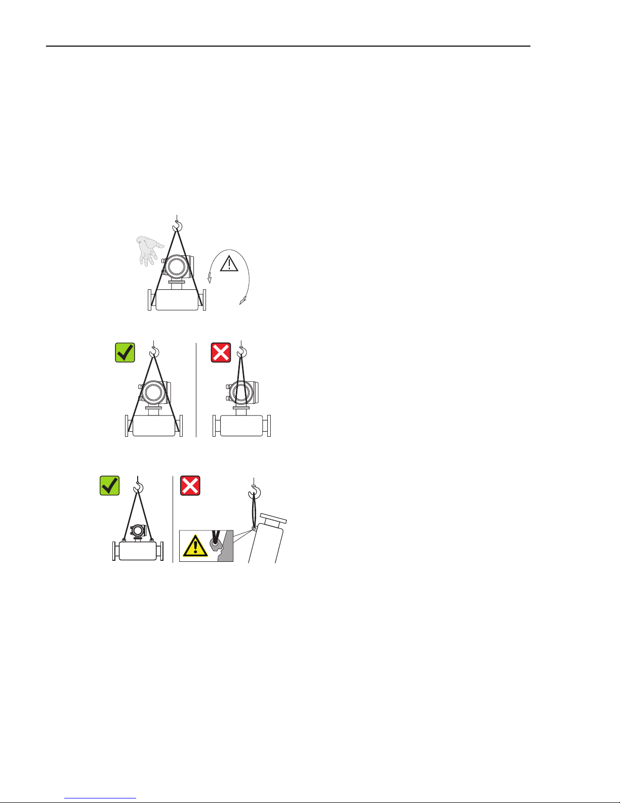
To transport the unit, use slings slung around the process
connections or use lugs (if available).
#
Warning!
Risk of injury! The device can slip.
The center of gravity of the measuring device may be
higher than the holding points of the slings.
Always ensure that the device cannot slip or turn around
its axis.
A0007409
Do not lift measuring devices by the transmitter housing
or the connection housing in the case of the remote
version. Do not use chains as they could damage the
housing.
A0007409
The assembly must always be attached to at least two
lifting eyes.
Page 7

Proline Promass 83 Installation
Endress+Hauser
7
2.2 Installation conditions
For mechanical reasons, and in order to protect the piping, it is advisable to support heavy
sensors.
2.2.1 Dimensions
For the dimensions of the measuring device see associated Technical Information on the
CD-ROM.
2.2.2 Mounting location
The following mounting locations are recommended:
• Upstream from assemblies such as valves, T-pieces, elbows, etc.
• On the pressure side of pumps (for high system pressure)
• At the lowest point in an ascending pipe (for high system pressure)
The following mounting locations should be avoided:
• At the highest point in a pipe (risk of air accumulating)
• In an open down pipe directly upstream from a free pipe outlet. For ways of using the
measuring device in down pipes, see the related Operating Instructions on the CD-ROM.
Page 8
Installation Proline Promass 83
8 Endress+Hauser
2.2.3 Orientation
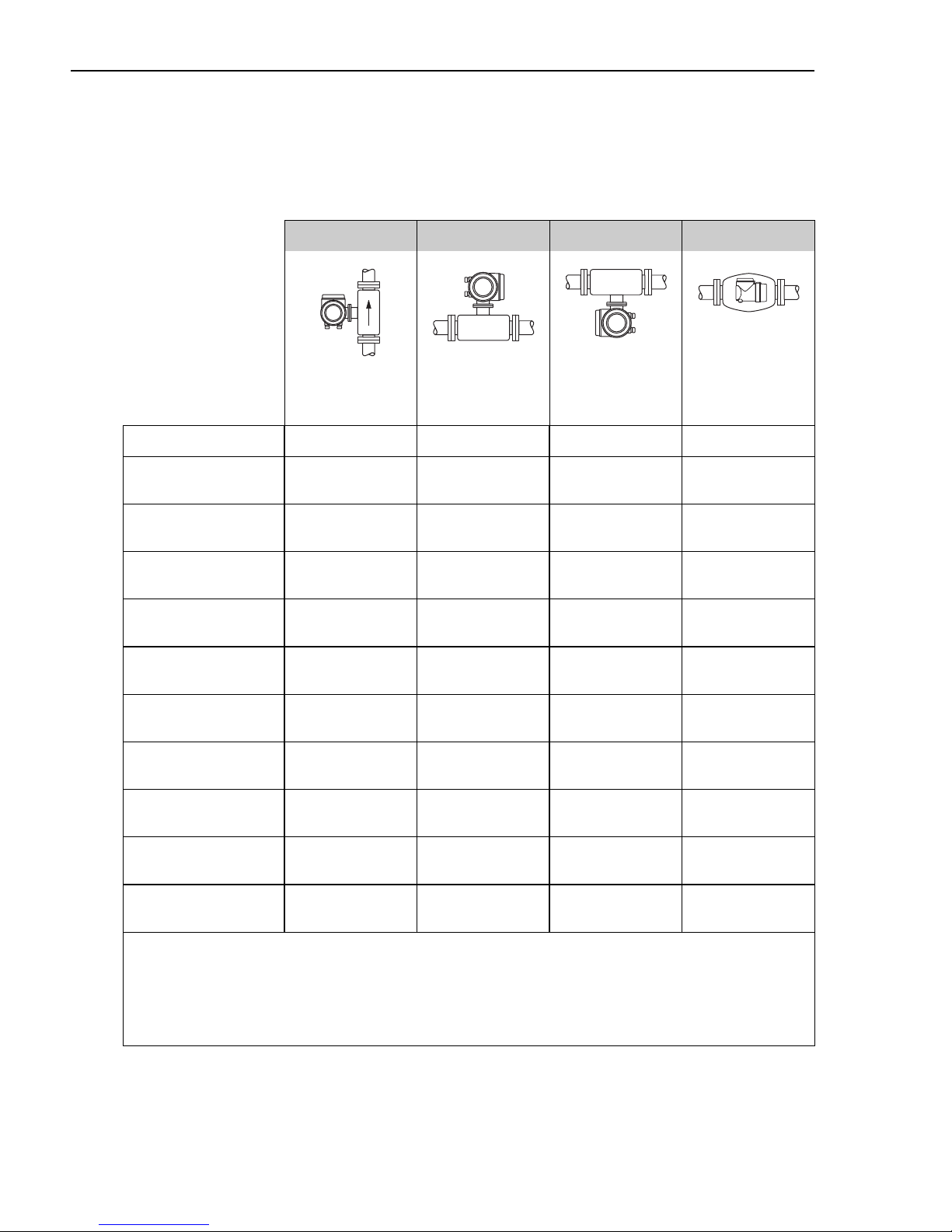
• The direction of the arrow on the nameplate of the measuring device must match the flow
direction of the fluid.
• The following table lists the possible orientations of the measuring devices:
Vertical Horizontal Horizontal Horizontal
A0004572
A0004576
A0004580
A0015445
Transmitter at the
side
Transmitter at the
top
Transmitter at the
bottom
Transmitter at the
side
Promass A Recommended Possible (
m
) Possible (m, p) Not suitable
Promass E
Recommended
Recommended
(
n
)
Recommended
(o, p)
Not suitable
Promass F
Recommended
Recommended
(
n
)
Recommended
(o, p)
Not suitable
Promass F HT*
Compact version
Recommended Not suitable
Recommended
(
o, p
)
Not suitable
Promass F HT*
Remote version
Recommended Possible (
n
)
Recommended
(
o, p
)
Not suitable
Promass H
Recommended Recommended
Recommended
(
p
)
Recommended
Promass I
Recommended Recommended
Recommended
(
p
)
Recommended
Promass P
Recommended Recommended
Recommended
(
p
)
Recommended
Promass S
Recommended Recommended
Recommended
(
p
)
Recommended
Promass O
Recommended
Recommended
(
n
)
Recommended
(o, p)
Not suitable
Promass X
Recommended Recommended
Recommended
(
p
)
Possible
*HT = high temperature version for medium temperatures (TM) > 200 °C (392 °F)
m
Do not install the measuring device in such a way that is suspended without any support or securing unit.
n
This orientation is not suitable for fluids with entrained solids.
o
This orientation is not suitable for outgassing fluids.
p
This orientation is not suitable for low fluid temperatures.
Page 9
Proline Promass 83 Installation
Endress+Hauser
9
Special installation instructions for Promass A
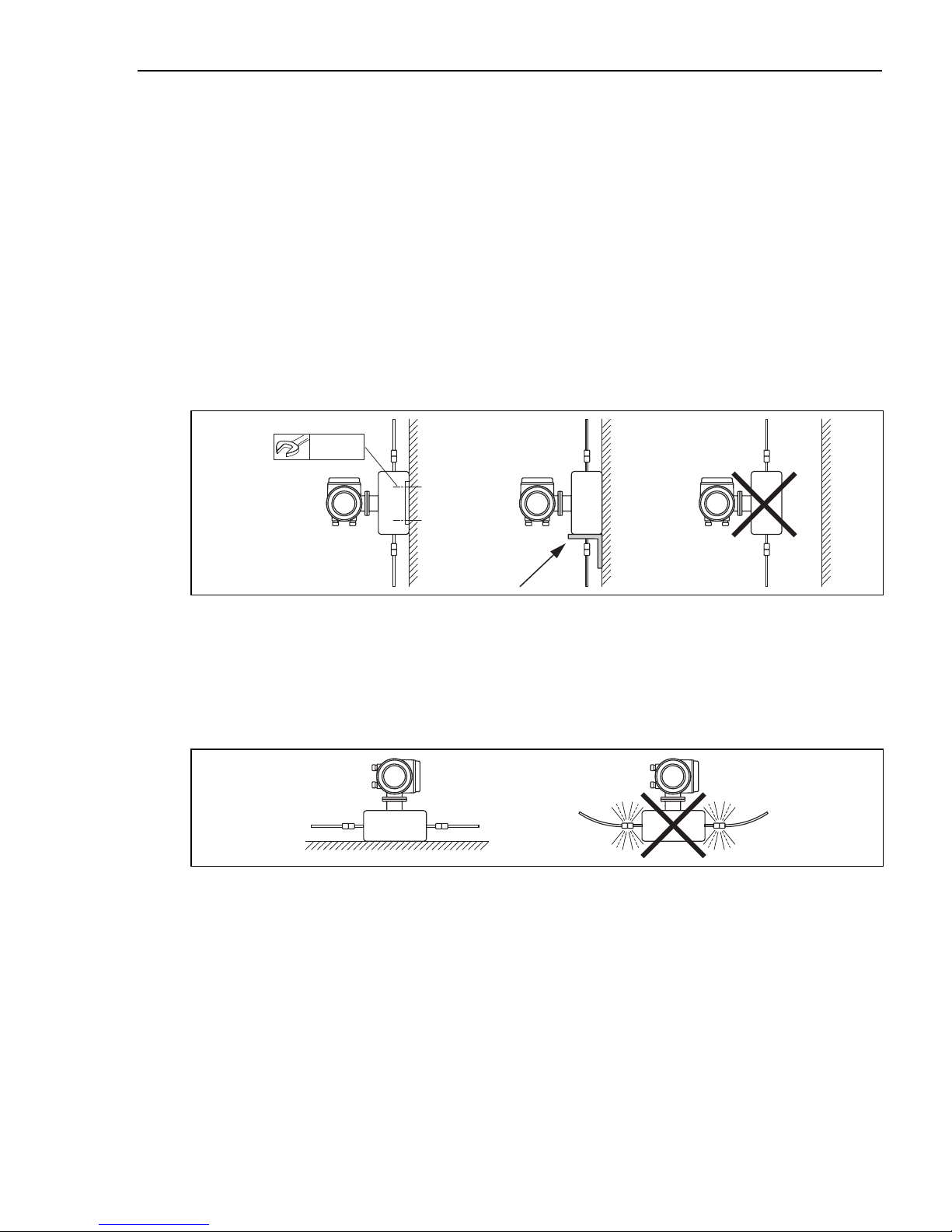
"
Caution!
Risk of measuring pipe fracture if sensor installed incorrectly!
The sensor may not be installed in a pipe as a freely suspended sensor:
• Using the base plate, mount the sensor directly on the floor, the wall or the ceiling.
• Support the sensor on a firmly mounted support base (e.g. angle bracket).
Vertical
We recommend two installation versions when mounting vertically:
• Mounted directly on a wall using the base plate
• Measuring device supported on an angle bracket mounted on the wall
A0018980
Horizontal
We recommend the following installation version when mounting horizontally:
• Measuring device standing on a firm support base
A0018979
2.2.4 Heating
For information on the heating, please see the Operating Instructions on the CD-ROM.
2.2.5 Thermal insulation
For information on the thermal insulation, please see the Operating Instructions on the
CD-ROM.
10 mm
4 x
Page 10
Installation Proline Promass 83
10 Endress+Hauser
2.2.6 Inlet and outlet runs
No inlet and outlet runs are required.
2.2.7 Vibrations
No measures are necessary.
2.3 Post-installation
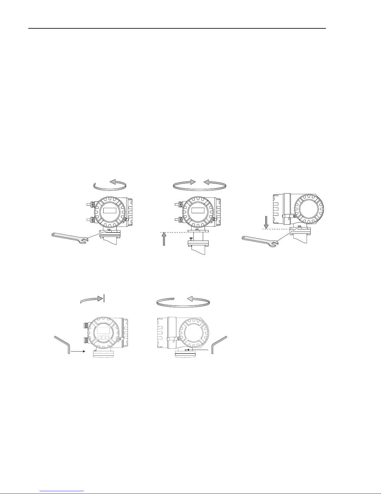
2.3.1 Turning the transmitter housing
Turning the aluminum field housing
Aluminum field housing for non-Ex area
Aluminum field housing for Zone 1 or Class I Div. 1
A0007540
A0008036
a. Release the setscrew.
b. Turn the transmitter housing
gently clockwise until the stop
(end of the thread).
c. Turn the transmitter
counterclockwise (max. 360°)
to the desired position.
d. Retighten the setscrew.
c
e
f
a
b
d
£ 180° £ 180°
N
i
c
h
t
u
n
t
e
r
S
p
a
n
n
u
n
g
ö
f
f
n
e
n
K
e
e
p
c
o
v
e
r
t
i
g
h
t
w
h
i
l
e
c
i
r
c
u
i
t
s
a
r
e
a
l
i
v
e
N
e
p
a
s
o
u
v
r
i
r
l
’
a
p
p
a
r
e
i
l
s
o
u
s
t
e
n
s
i
o
n
K
e
e
p
c
o
v
e
r
t
i
g
h
t
w
h
i
l
e
c
i
r
c
u
i
t
s
a
r
e
a
l
i
v
e
max. 360°
Nicht-eigensichere
Stromkreise durch
IP40-Abdeckung geschützt
Non-intrinsically safe
circuits Ip40 protected
Boucles de courant
sans sécurité intrinsèque
protégées par Ip40
c
a
b
d
Page 11
Proline Promass 83 Installation
Endress+Hauser
11
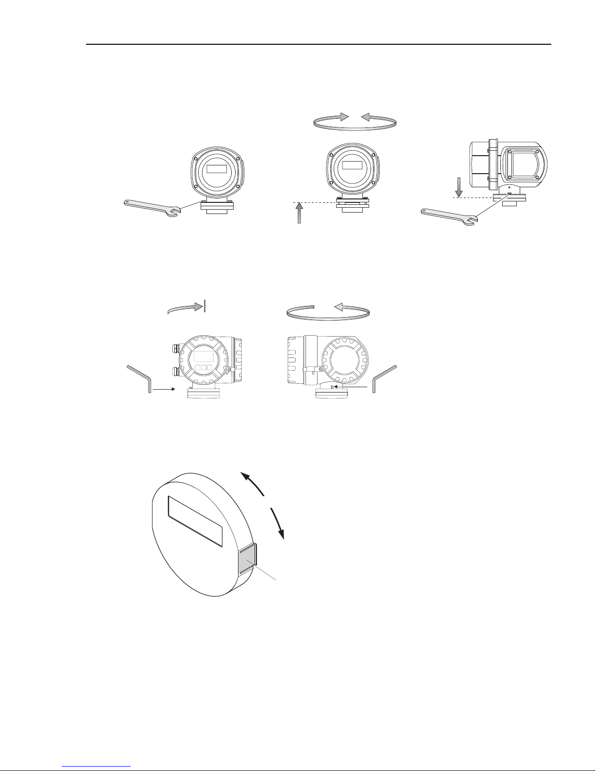
Turning the stainless steel field housing
A0007661
2.3.2 Turning the onsite display
A0008036
a. Release the setscrew.
b. Turn the transmitter housing
gently clockwise until the stop
(end of the thread).
c. Turn the transmitter
counterclockwise (max. 360°)
to the desired position.
d. Retighten the setscrew.
A0007541
a. Press in the side latches on the display module and
remove the module from the cover plate of the
electronics compartment.
b. Turn the display to the desired position
(max. 4 × 45° in both directions) and reset it onto
the cover plate of the electronics compartment.
a
b
c
d
e
£ 180° £ 180°
N
i
c
h
t
u
n
t
e
r
S
p
a
n
n
u
n
g
ö
f
f
n
e
n
K
e
e
p
c
o
v
e
r
t
i
g
h
t
w
h
i
l
e
c
i
r
c
u
i
t
s
a
r
e
a
l
i
v
e
N
e
p
a
s
o
u
v
r
i
r
l
’
a
p
p
a
r
e
i
l
s
o
u
s
t
e
n
s
i
o
n
K
e
e
p
c
o
v
e
r
t
i
g
h
t
w
h
i
l
e
c
i
r
c
u
i
t
s
a
r
e
a
l
i
v
e
max. 360°
Nicht-eigensichere
Stromkreise durch
IP40-Abdeckung geschützt
Non-intrinsically safe
circuits Ip40 protected
Boucles de courant
sans sécurité intrinsèque
protégées par Ip40
c
a
b
d
4 × 45°
a
b
Page 12
Installation Proline Promass 83
12 Endress+Hauser
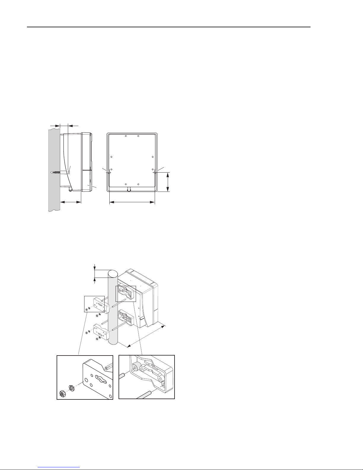
2.3.3 Installing the wall-mount housing
"
Caution!
• Make sure that the ambient temperature does not exceed the permitted range.
• Always install the wall-mount housing in such a way that the cable entries point downwards.
Mounted directly on the wall
Pipe mounting
A0007542
1. Connection compartment
2. Securing screws M6 (max. ø 6.5 mm (0.25");
screw head max. ø 10.5 mm (0.4"))
3. Housing bores for securing screws
A0007543
"
Caution!
Danger of overheating! If the device is mounted on a
warm pipe, make sure that the housing temperature
does not exceed +60 °C (+140 °F) which is the
maximum temperature permitted.
1
2
3
3
90 (3.54)
35 (1.38)
192 (7.56)
81.5 (3.2)
mm (inch)
mm (inch)
Ø 20…70
(Ø 0.79…2.75)
~ ~ 6.1)155 (
Page 13
Proline Promass 83 Installation
Endress+Hauser
13
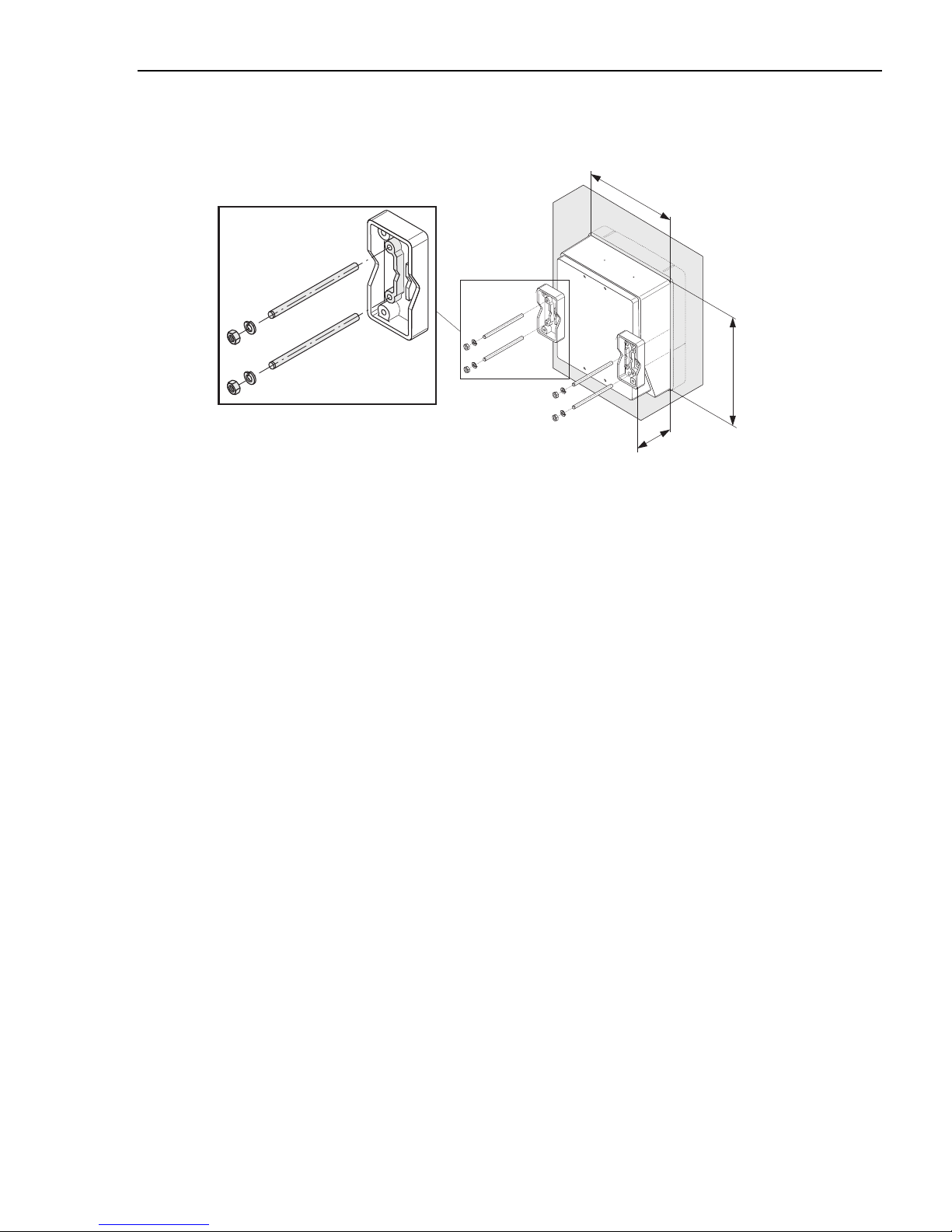
Panel mounting
A0007544
2.4 Post-installation check
• Is the measuring device damaged (visual inspection)?
• Does the measuring device correspond to the specifications at the measuring point?
• Is the serial number of sensor and the connected transmitter the same?
• Are the measuring point number and labeling correct (visual inspection)?
• Correct internal diameter and correct surface roughness/quality?
• Has the correct sensor orientation been selected in terms of type, fluid properties, fluid
temperature?
• Does the arrow on the sensor point in the direction of the flow in the pipe?
• Is the measuring device protected against moisture and sunlight?
• Is the measuring device protected against overheating?
245 (9.65)
~110 (~4.33)
210 (8.27)
+0.5 (+0.019)
–0.5 (–0.019)
+0.5 (+0.019)
–0.5 (–0.019)
mm (inch)
Page 14

Wiring Proline Promass 83
14 Endress+Hauser
3Wiring
#
Warning!
Risk of electric shock! Components carry dangerous voltages.
• Never mount or wire the measuring device while it is connected to the power supply.
• Prior to connecting the power supply, connect the protective ground to the ground terminal
on the housing.
• Route the power supply and signal cables so they are securely seated.
• Seal the cable entries and covers so they are airtight.
"
Caution!
Risk of damaging the electronic components!
• Connect the power supply in accordance with the connection data on the nameplate.
• Connect the signal cable in accordance with the connection data in the Operating Instructions
or the Ex documentation on the CD-ROM.
In addition, for the remote version:
"
Caution!
Risk of damaging the electronic components!
• Only connect sensors and transmitters with the same serial number
• Observe the cable specifications of the connecting cable Operating Instructions on the
CD-ROM.
!
Note!
Install the connecting cable securely to prevent movement.
In addition, for measuring devices with fieldbus communication:
"
Caution!
Risk of damaging the electronic components!
• Observe the cable specification of the fieldbus cable Operating Instructions on the
CD-ROM.
• Keep the stripped and twisted lengths of cable shield as short as possible.
• Screen and ground the signal lines Operating Instructions on the CD-ROM.
• When using in systems without potential matching Operating Instructions on the
CD-ROM.
In addition, for Ex-certified measuring devices:
#
Warning!
When wiring Ex-certified measuring devices, all the safety instructions, wiring diagrams,
technical information, etc. of the related Ex documentation must be observed
Ex documentation on the CD-ROM.
Page 15
Proline Promass 83 Wiring
Endress+Hauser
15
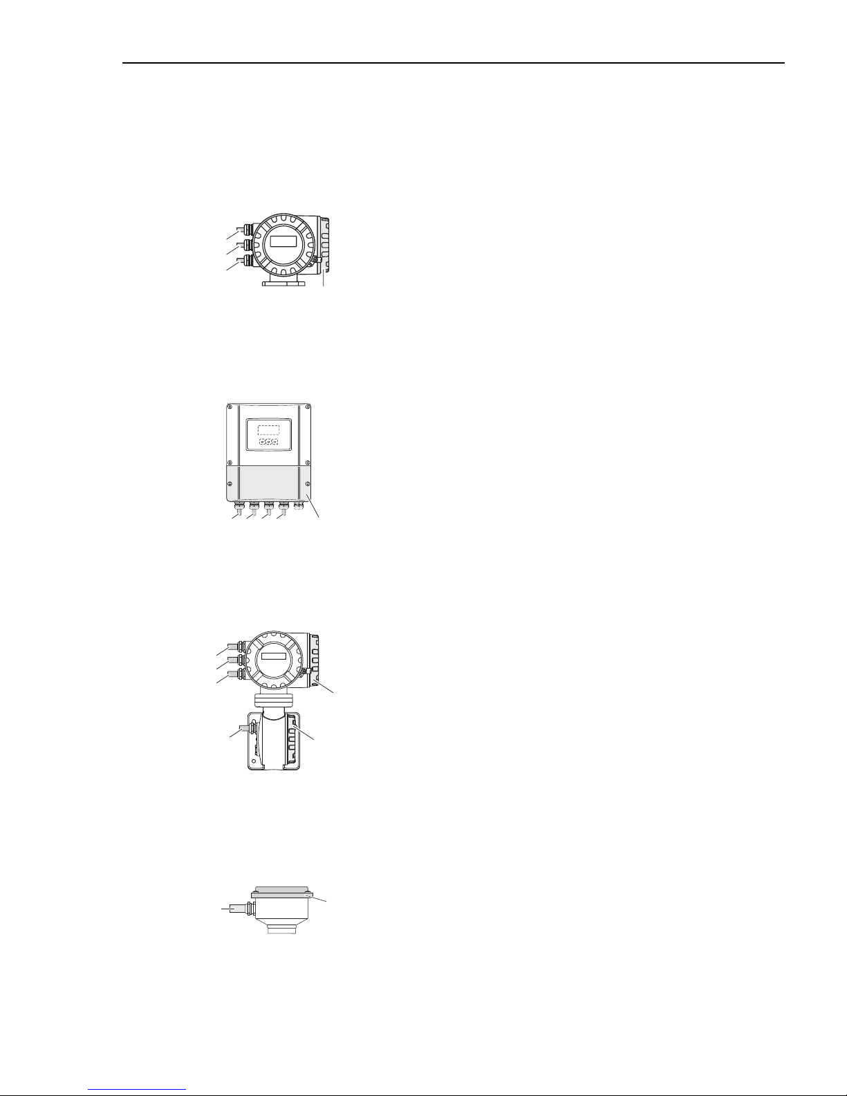
3.1 Connecting the various housing types
Wire the unit using the terminal assignment diagram inside the cover.
3.1.1 Compact version
3.1.2 Remote version (transmitter): non-Ex Zone, Ex Zone 2, Class I Div. 2
3.1.3 Remote version (transmitter): Ex Zone 1, Class I Div. 1
3.1.4 Remote version (sensor)
A0007545
Transmitter connection:
1
2
3
4
Connection diagram inside the
connection compartment cover
Power supply cable
Signal cable or fieldbus cable
Optional
A0007546
Transmitter connection:
1
2
3
4
Connection diagram inside the
connection compartment cover
Power supply cable
Signal cable
Fieldbus cable
Connecting cable connection:
5 Sensor/transmitter connecting cable
A0007547
Transmitter connection:
1
2
3
4
Connection diagram inside the
connection compartment cover
Power supply cable
Signal cable or fieldbus cable
Optional
Connecting cable connection:
5 Sensor/transmitter connecting cable
A0008037
Transmitter connection:
1 Connection diagram inside the connection compartment cover
Connecting cable connection:
5 Sensor/transmitter connecting cable
1
2
3
4
2
3
1
4 5
c
i
r
c
u
i
t
s
a
r
e
a
l
i
v
e
s
o
u
s
t
e
n
s
i
o
n
c
i
r
c
u
i
t
s
a
r
e
a
l
i
v
e
N
i
c
h
t
u
n
t
e
r
S
p
a
n
n
u
n
g
ö
f
f
n
e
n
K
e
e
p
c
o
v
e
r
t
i
g
h
t
w
h
i
l
e
N
e
p
a
s
o
u
v
r
i
r
l
’
a
p
p
a
r
e
i
l
K
e
e
p
c
o
v
e
r
t
i
g
h
t
w
h
i
l
e
c
i
r
c
u
i
t
s
a
r
e
a
l
i
v
e
2
3
5
1
1
4
5
1
Page 16
Wiring Proline Promass 83
16 Endress+Hauser
3.2 Degree of protection
The devices meet all the requirements for IP 67 (NEMA 4X).
After mounting in the field or service work, the following points have to be observed to ensure
that IP 67 (NEMA 4X) protection is retained:
• Install the measuring device in such a way that the cable entries do not point upwards.
• Do not remove the seal from the cable entry.
• Remove all unused cable entries and insert blanking or certified plugs instead.
• Use cable entries and drain plugs with a long-term operating temperature range in accordance
with the temperature specified on the nameplate.
3.3 Post-connection check
• Are cables or the device damaged (visual inspection)?
• Does the supply voltage match the information on the nameplate?
• Do the cables used comply with the necessary specifications?
• Do the mounted cables have adequate strain relief and are they routed securely?
• Is the cable type route completely isolated? Without loops and crossovers?
• Are all screw terminals firmly tightened?
• Are all cable entries installed, firmly tightened and correctly sealed?
• Cable routed as a "water trap" in loops?
• Are all the housing covers installed and securely tightened?
In addition, for measuring devices with fieldbus communication:
• Are all the connecting components (T-boxes, junction boxes, connectors, etc.) connected
with each other correctly?
• Has each fieldbus segment been terminated at both ends with a bus terminator?
• Has the max. length of the fieldbus cable been observed in accordance with the specifications?
• Has the max. length of the spurs been observed in accordance with the specifications?
• Is the fieldbus cable fully shielded and correctly grounded?
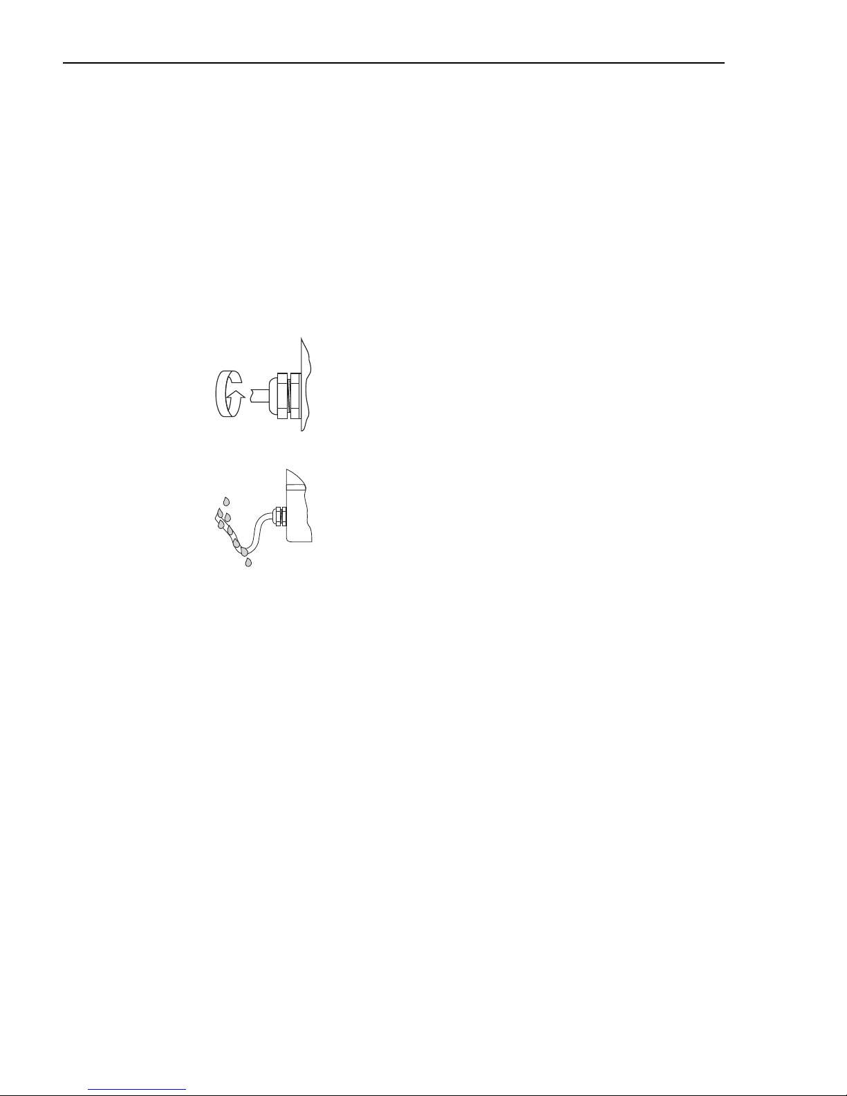
A0007549
Tighten the cable entries correctly.
A0007550
The cables must loop down before they enter the cable
entries ("water trap").
Page 17
Proline Promass 83 Hardware settings
Endress+Hauser
17
4 Hardware settings
This section only deals with the hardware settings needed for commissioning. All other settings
(e.g. output configuration, write protection, etc.) are described in the associated Operating
Instructions on the CD-ROM.
!
Note!
No hardware settings are needed for measuring devices with HART or FOUNDATION
Fieldbus-type communication.
4.1 Device address PROFIBUS DP/PA, Modbus RS485
Has to be set for measuring devices with the following communication methods:
•PROFIBUS DP/PA
• Modbus RS485
The device address can be configured via:
• Miniature switches see description below
• Local operation see section Software settings, "Device address PROFIBUS DP/PA,
Modbus RS485"
ä 25
Addressing via miniature switches
#
Warning!
Risk of electric shock! Risk of damaging the electronic components!
• All the safety instructions for the measuring device must be observed and all the warnings
heeded ä 14.
• Use a workspace, working environment and tools purposely designed for electrostatically
sensitive devices.
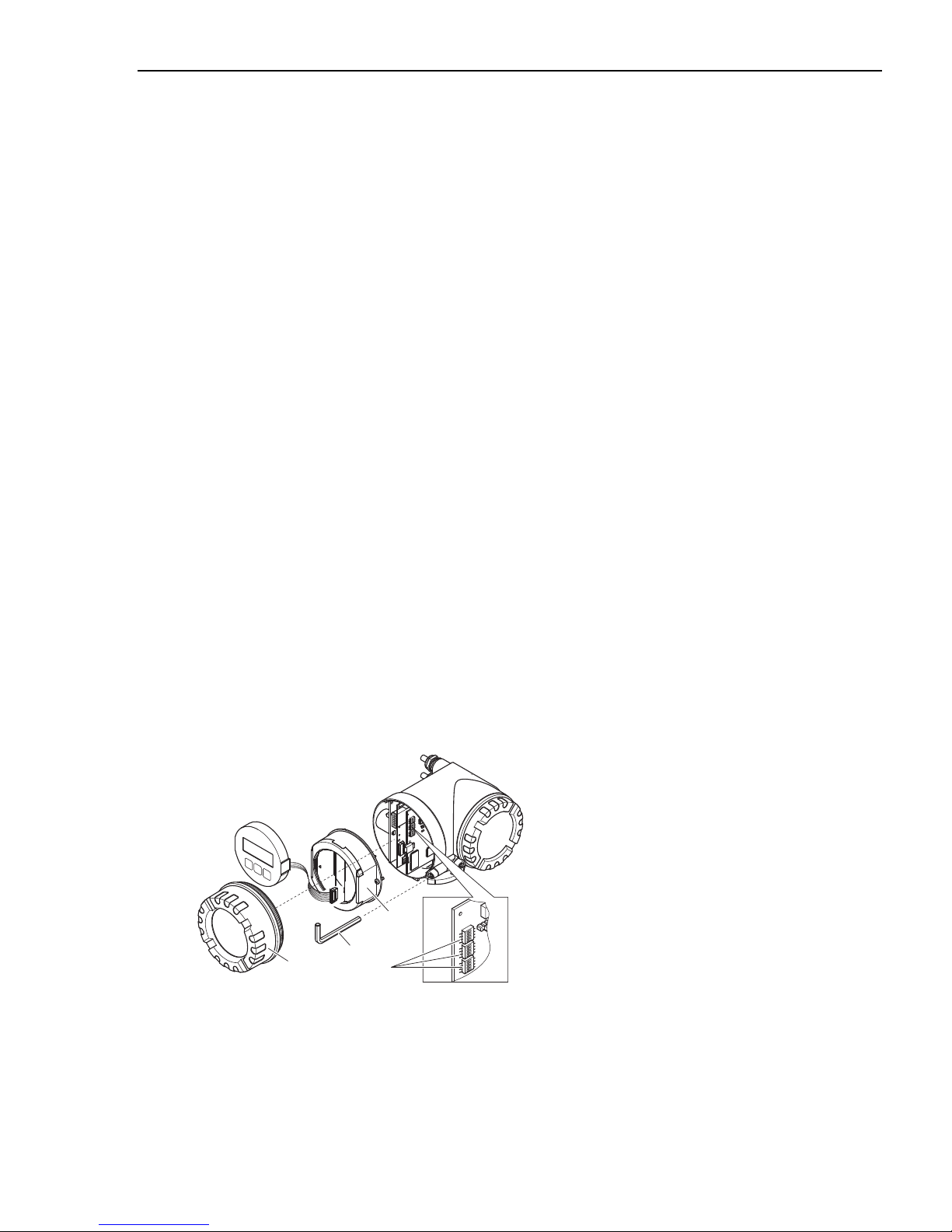
A0007551
#
Warnung!
Switch off the power supply before opening the device.
a. Loosen the cheese head screw of the securing
clamp with an Allen key (3 mm / 0.12 in)
b. Unscrew cover of the electronics compartment
from the transmitter housing.
c. Loosen the securing screws of the display module
and remove the onsite display (if present).
d. Set the position of the miniature switches on the
I/O board using a sharp pointed object.
Installation is the reverse of the removal procedure.
1
2
3
4
W
E
N
O
1
2
3
4
W
E
N
O
1
2
3
4
W
E
N
O
1
2
3
4
W
E
N
O
1
2
3
4
W
E
N
O
1
2
3
4
W
E
N
O
a
b
c
d
Page 18
Hardware settings Proline Promass 83
18 Endress+Hauser
PROFIBUS DP/PA
Modbus RS485
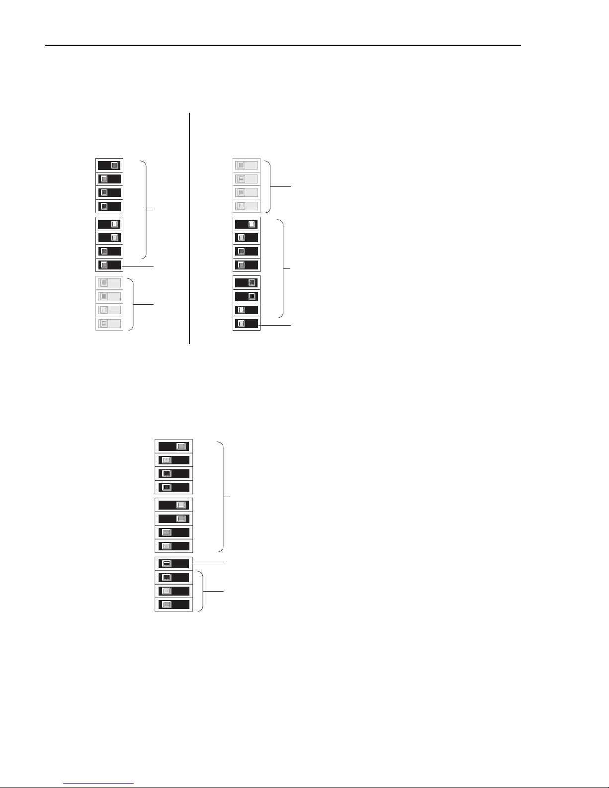
A0007552
Device address range: 0 to 126
Factory setting: 126
a. Miniature switches for device address
Example shown:
1+16+32 = device address 49
b. Miniature switches for the address mode (method
of addressing):
– OFF (factory setting) = software addressing via
local operation/operating program
– ON = hardware addressing via miniature
switches
c. Miniature switch not assigned.
A0007554
Device address range: 1 to 247
Factory setting: 247
a. Miniature switches for device address
Example shown:
1+16+32 = device address 49
b. Miniature switches for the address mode (method
of addressing):
– OFF (factory setting) = software addressing via
local operation/operating program
– ON = hardware addressing via miniature
switches
c. Miniature switch not assigned.
161
3
322
4
643
4
1
2
b
OFF ON
11
22
43
84
a
OFF ON
c
161
3
322
4
643
4
1
2
b
OFF ON
11
22
43
84
a
OFF ON
c
DP PA
161
3
32
2
4
64
3
1284
1
2
b
OFF ON
11
2
2
43
84
a
OFF ON
c
Page 19
Proline Promass 83 Hardware settings
Endress+Hauser
19
4.2 Device address EtherNet/IP network
Has to be set for measuring devices with the communication method:
• EtherNet/IP
The IP address can be configured via:
• Miniature switches see description below
• Webserver see section Software settings, "Device address EtherNet/IP network"
ä 26
Addressing via miniature switches
#
Warning!
Risk of electric shock! Risk of damaging the electronic components!
• All the safety instructions for the measuring device must be observed and all the warnings
heeded ä 14.
• Use a workspace, working environment and tools purposely designed for electrostatically
sensitive devices.
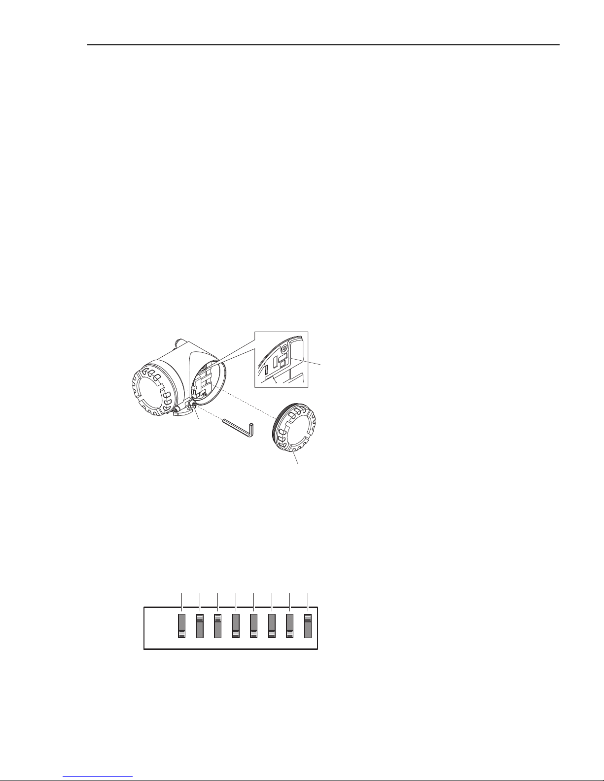
A0015112
a. Loosen the cheese head screw of the securing
clamp (1) with an Allen key (3 mm / 0.12 in).
b. Unscrew cover of the electronics compartment (2)
from the transmitter housing.
c. Set the position of the miniature switches (3) on
the I/O board using a sharp pointed object.
Installation is the reverse of the removal procedure.
IP address range: 0 to 254
Default setting: 192.168.212.212 (all miniature switches
= OFF)
A0015114
Example shown:
64+32+1 = IP address 192.168.212.97
Activation hardware addressing:
After 10 seconds the hardware addressing with the defined IP address is activated.
!
Note!
Deactivation hardware addressing and activation software
addressing ( ä 26):
Switch all the DIP switches for hardware addressing to
OFF.
1
2
3
128
ON
OFF
64
32
16
8
4
2
1
8765 4321
Page 20
Hardware settings Proline Promass 83
20 Endress+Hauser
4.3 Terminating resistors
!
Note!
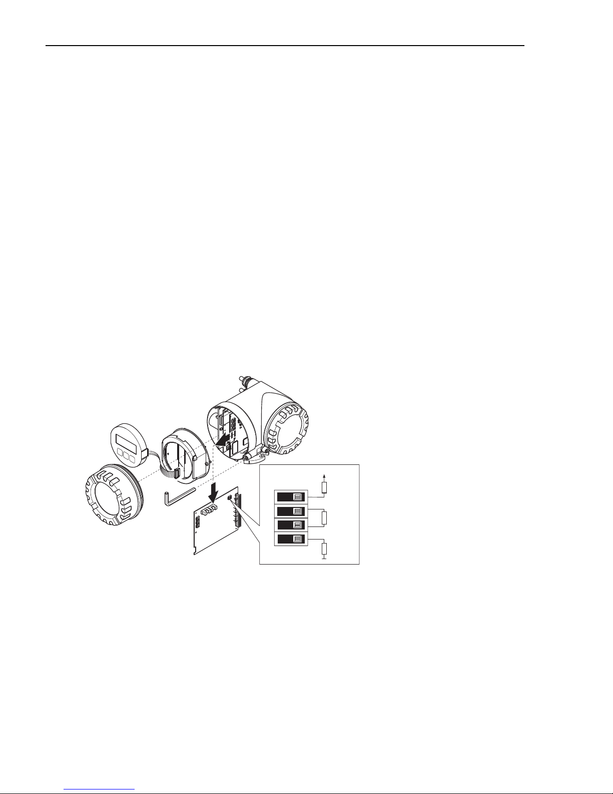
If the measuring device is used at the end of a bus segment, termination is required.
This can be performed in the measuring device by setting the terminating resistors on the
I/O board. Generally, however, it is recommended to use an external bus terminator and not
perform termination at the measuring device itself.
Has to be set for measuring devices with the following communication methods:
• PROFIBUS DP
– Baudrate 1.5 MBaud Termination can be performed at the measuring device, see
graphic
– Baudrate > 1.5 MBaud An external bus terminator must be used
• Modbus RS485 Termination can be performed at the measuring device, see graphic
#
Warning!
Risk of electric shock! Risk of damaging the electronic components!
• All the safety instructions for the measuring device must be observed and all the warnings
heeded ä 14.
• Use a workspace, working environment and tools purposely designed for electrostatically
sensitive devices.
A0007556
Setting the terminating switch SW1
on the I/O board:
ON - ON - ON - ON
1
2
3
4
W
E
N
O
1
2
3
4
W
E
N
O
1
2
3
4
W
E
N
O
1
2
3
4
W
E
N
O
1
2
3
4
W
E
N
O
1
2
3
4
W
E
N
O
1
2
3
4
W
E
N
O
390 W
+5V
3
4
1
2
OFF ON
220 W
390 W
SW 1
Page 21
Proline Promass 83 Commissioning
Endress+Hauser
21
5 Commissioning
5.1 Switching on the measuring device
On completion of the installation (successful post-installation check), wiring (successful
post-connection check) and after making the necessary hardware settings, where applicable, the
permitted power supply (see nameplate) can be switched on for the measuring device.
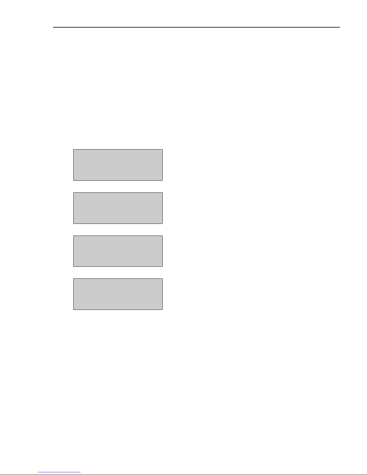
When the power supply is switched on, the measuring device performs a number of power-up
checks and device self-checks. As this procedure progresses the following messages can appear
on the onsite display:
The measuring device starts operating as soon as the startup procedure is complete.
Various measured values and/or status variables appear on the display.
!
Note!
If an error occurs during startup, this is indicated by an error message.
The error messages that occur most frequently when a measuring device is commissioned are
described in the Troubleshooting section ä 28.
Display examples:
PROMASS 83
START-UP
RUNNING
Start-up message
Æ
PROMASS 83
DEVICE SOFTWARE
V XX.XX.XX
Displays the current software
Æ
CURRENT OUTPUT
FREQUENCY OUTPUT
RELAY
STATUS INPUT
List of input/output modules available
Æ
SYSTEM OK
OPERATION
Beginning of operation
Page 22
Commissioning Proline Promass 83
22 Endress+Hauser
5.2 Operation
5.2.1 Display elements
5.2.2 Operating elements
5.2.3 Displaying error messages
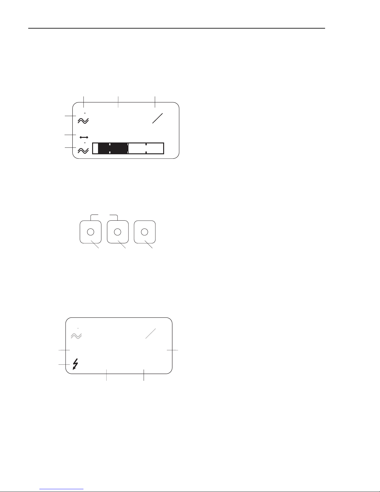
A0007663
Display lines/fields
1. Main line for primary measured values
2. Additional line for additional measured
variables/status variables
3. Information line for bar graph display for example
4. Info icons, e.g. volume flow
5. Current measured values
6. Engineering units/time units
A0007559
Operating keys
1. (–) Minus key for entering, selecting
2. (+) Plus key for entering, selecting
3. Enter key for calling the function matrix, saving
When the +/– keys are pressed simultaneously (Esc):
• Exit the function matrix step-by-step:
• > 3 sec. = cancel data input and
return to the measured value display
A0007664
1. Type of error:
P = Process error, S = System error
2. Error message type:
$
= Fault message, ! = Notice message
3. Error number
4. Duration of the last error that occurred:
Hours: Minutes: Seconds
5. Error designation
• List of the most common error messages during
commissioning ä 28
• List of all error messages, see associated Operating
Instructions on the CD-ROM
1
45
6
2
3
+24.502
+1863.97
x
x
y
y
–50
+50
%
v
v
3
S
Esc
E
+
-
1 2 3
+24.502
x
y
v
XXXXXXXXXX
#000 00:00:05
P
3 4
2
1 5
Page 23
Proline Promass 83 Commissioning
Endress+Hauser
23
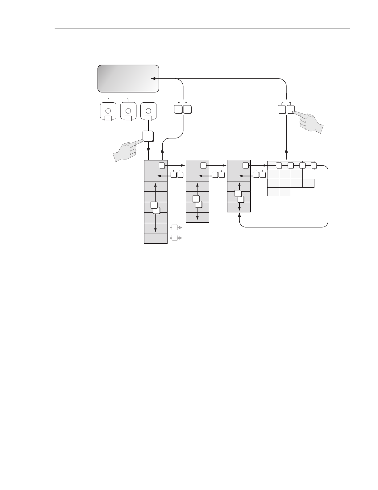
5.3 Navigating within the function matrix
A0007665
1.
F
Enter the function matrix (starting with measured value display)
2.
P
Select the Block (e.g. USER INTERFACE)
F
Confirm selection
3.
P
Select the group (e.g. CONTROL)
F
Confirm selection
4.
P
Select the function group (e.g. BASIC CONFIGURATION)
F
Confirm selection
5.
N
Select function (e.g. LANGUAGE)
6.
P
Enter code 83 (only for the first time you access the function matrix)
F
Confirm entry
P
Change function/selection (e.g. ENGLISH)
F
Confirm selection
7.
Q
Return to measured value display step by step
8.
Q
> 3 s Return immediately to measured value display
Esc
E
+
-
>3s
E
+
Esc
–
+
Esc
–
m
opq
s
n
E
E
–
+
E
+
– –
+
E
+
–
–
+
–
+
E E E E
r
ss
st
E
Page 24

Commissioning Proline Promass 83
24 Endress+Hauser
5.4 Calling the Commissioning Quick Setup
All the functions needed for commissioning are called up automatically with the Quick Setup.
The functions can be changed and adapted to the process in question.
1.
F
Enter the function matrix (starting with measured value display)
2.
P
Select the group QUICK SETUP
F
Confirm selection
3. QUICK SETUP COMMISSIONING function appears.
4. Intermediate step if configuration is blocked:
P
Enter the code 83 (confirm with F ) and thus enable configuration
5.
P
Go to Commissioning Quick Setup
6.
P
Select YES
F
Confirm selection
7.
F
Start Commissioning Quick Setup
8. Configure the individual functions/settings:
– Via P-key, select option or enter number
– Via F-key, confirm entry and go to next function
– Via
Q
-key, return to Setup Commissioning function
(settings already made are retained)
!
Note!
Observe the following when performing the Quick Setup:
• Configuration selection: Select the ACTUAL SETTING option
• Unit selection: This is not offered again for selection after configuring a unit
• Output selection: This is not offered again for selection after configuring an output
• Automatic configuration of the display: select YES
– Main line = Mass flow
– Additional line = Totalizer 1
– Information line = Operating/system conditions
• If asked whether additional Quick Setups should be executed: select NO
All the available functions of the measuring device and their configuration options as well as
additional Quick Setups, if available, are described in detail in the "Description of Device
Functions" Operating Instructions. The related Operating Instructions can be found on the
CD-ROM.
The measuring device is ready for operation on completion of the Quick Setup.
Page 25

Proline Promass 83 Commissioning
Endress+Hauser
25
5.5 Software settings
5.5.1 Device address PROFIBUS DP/PA, Modbus RS485
Has to be set for measuring devices with the following communication methods:
•PROFIBUS DP
Device address range 0 to 126, factory setting 126
• Modbus RS485
Device address range 1 to 247, factory setting 247
The device address can be configured via:
• Miniature switches see section Hardware settings, "Device address PROFIBUS DP/PA,
Modbus RS485" ä 17
• Local operation see description below
!
Note!
The COMMISSIONING SETUP must be executed before setting the device address.
Calling the Communication Quick Setup
1.
F
Enter the function matrix (starting with measured value display)
2.
P
Select the group QUICK SETUP
F
Confirm selection
3.
N
Select the QUICK SETUP COMMUNICATION function
4. Intermediate step if configuration is blocked:
P
Enter the code 83 (confirm with F ) and thus enable configuration
5.
P
Go to Communication Quick Setup
6.
P
Select YES
F
Confirm selection
7.
F
Start Communication Quick Setup
8. Configure the individual functions/settings:
– Via P-key, select option or enter number
– Via F-key, confirm entry and go to next function
– Via
Q
-key, return to Setup Commissioning function
(settings already made are retained)
All the available functions of the measuring device and their configuration options as well as
additional Quick Setups, if available, are described in detail in the "Description of Device
Functions" Operating Instructions. The related Operating Instructions can be found on the
CD-ROM.
The measuring device is ready for operation on completion of the Quick Setup.
Page 26
Commissioning Proline Promass 83
26 Endress+Hauser
5.5.2 Device address EtherNet/IP network
Has to be set for measuring devices with the communication method:
• EtherNet/IP
The device address can be configured via:
• Miniature switches see section Hardware settings,
"Device address EtherNet/IP network" ä 19
• Webserver see description below
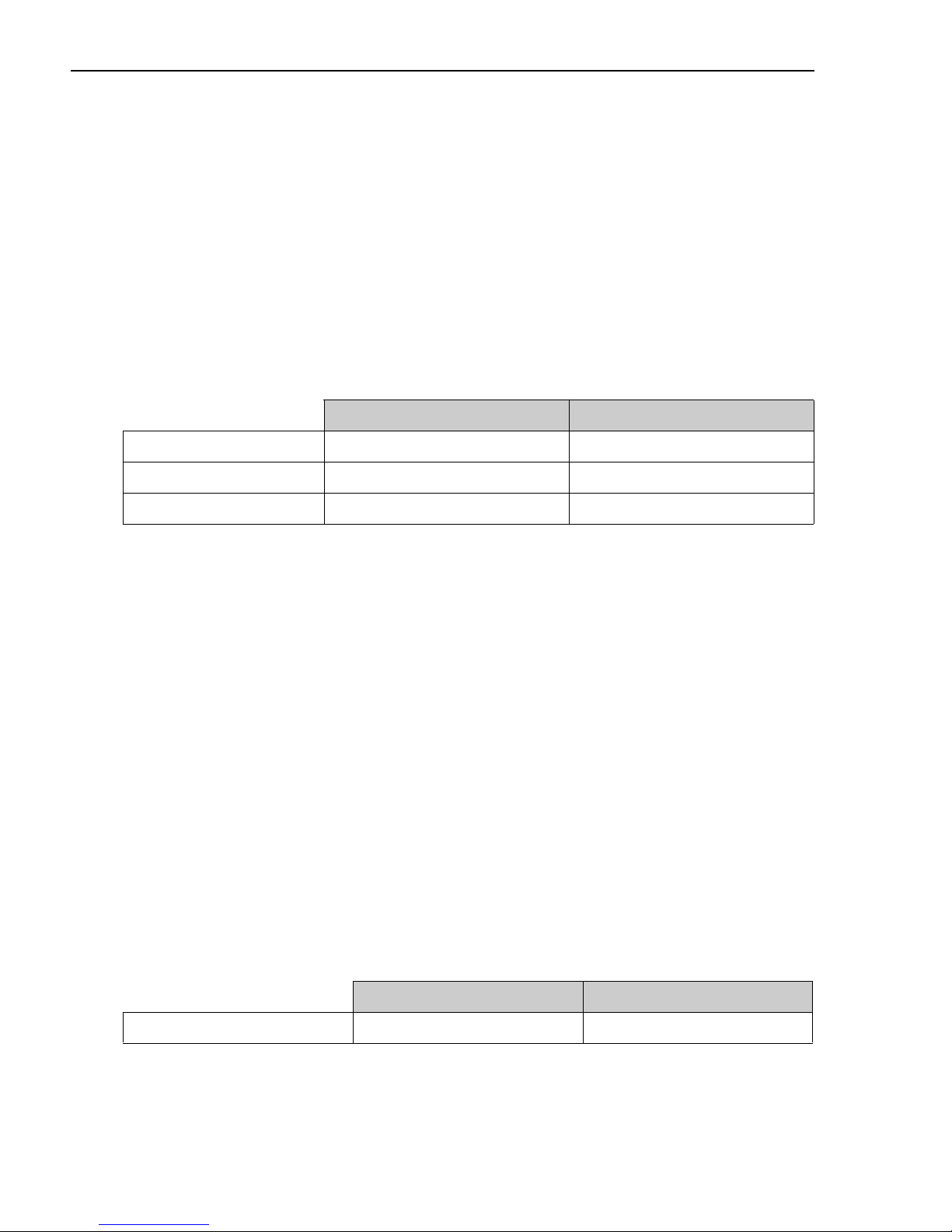
Software addressing is performed in the "Network Configuration" menu of the Webserver. Both
the IP address for the EtherNet/IP network and the IP address for the Webserver can be
configured. The measuring device has the following default addresses when delivered:
Addresses in the range from 0 to 254 are permitted (the address 255 is reserved for the broadcast
address).
!
Note!
• Software addressing is disabled if hardware addressing is activated ä 17.
• When changing from software addressing to hardware addressing, the first nine digits (first
three octets) that were configured using software addressing, remain unchanged.
• A reset of the software addressing to the default setting is possible see SD00138D.
DHCP client
If a DHCP server is used within the EtherNet/IP network, the IP address, gateway and subnet
mask are set automatically when the DHCP client function of the Webserver is enabled. The
MAC address of the measuring device is used for identification purposes.
The DHCP client function is enabled in the "Network Configuration" menu.
The measuring device has the following DHCP default settings when delivered:
!
Note!
The DHCP client function is disabled if hardware addressing is enabled ä 19.
EtherNet/IP network Webserver
IP address 192.168.212.212 192.168.212.213
Netmask 255.255.255.0 255.255.255.0
Gateway 192.168.212.212 192.168.212.213
EtherNet/IP network Webserver
DHCP Yes (enabled) No (disabled)
Page 27
Proline Promass 83 Commissioning
Endress+Hauser
27
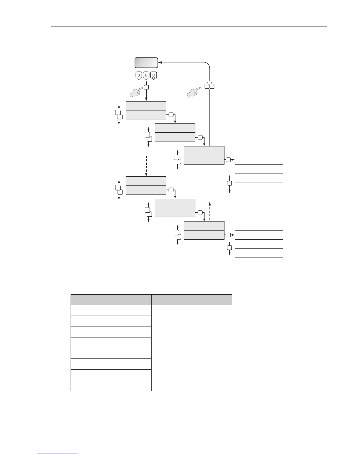
Displaying the address configurations via the local display
A0015115
The individual addressing parameters are assigned as follows:
Parameter Assignment
IP ADDRESS 1 EtherNet/IP network
SUBNETMASK 1
GATEWAY 1
MAC ADD. 1
IP ADDRESS 2 Webserver
SUBNETMASK 2
GATEWAY 2
MAC ADD. 2
-
+ E
Esc
>3s
+
Esc
–
–
+
…
BASIC FUNCTION
…
ETHERNET
E
–
+
…
CONFIGURATION
E
–
+
E
E
IP ADDRESS 1
SUBNETMASK 1
GATEWAY 1
IP ADDRESS 2
SUBNETMASK 2
GATEWAY 2
E
–
+
…
SUPERVISION
…
VERSION-INFO
E
–
+
…
E
–
+
E
SW-REV. SUB A/E
MAC ADD. 1
MAC ADD. 2
E
ETHERNET
Page 28
Commissioning Proline Promass 83
28 Endress+Hauser
5.6 Troubleshooting
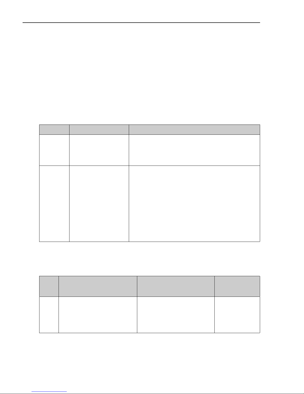
The error messages that can occur most frequently when a measuring device is commissioned
are described here.
A complete description of all the error messages Operating Instructions on the CD-ROM.
General
!
Note!
The output signals (e.g. pulse, frequency) of the measuring device must correspond to the
higher-order controller.
HART
FOUNDATION Fieldbus
No. Error message / Type Cause/remedy
351 to 354
System error message (S)/
Notice message (!)
CURRENT SPAN n
# 351 to 354
Current output
The current flow is outside the set range.
1. Change the upper range or lower range values entered
2. Increase or reduce flow, as applicable
701
Process error message (P)/
Notice message (!)
EXC. CURR. LIM
# 701
The maximum current value for the measuring tube exciter coils
has been reached since certain fluid characteristics, e.g. high gas or
solid content, are in the limit range. The device continues to work
correctly.
In particular with outgassing fluids and/or increased gas content,
the following measures are recommended to increase system
pressure:
1. Install the measuring device downstream of a pump
2. Mount the device at the lowest point in an ascending pipeline
3. Install a valve or an orifice plate downstream from the
measuring device
No. Error messages:
FOUNDATION Fieldbus (FF)*
(onsite display)
Analog Input function block
Error messages
Cause/remedy
701
Device status message (FF):
Current of the measuring tube
too high – Err. No. 701
Onsite display:
P: EXC. CURR. LIM
!: # 701
OUT. QUALITY = UNCERTAIN
OUT. SUBSTATUS = Non-specific
See HART table
Page 29
Proline Promass 83 Commissioning
Endress+Hauser
29
PROFIBUS
Modbus RS485
No. Device status message
(onsite display)
PROFIBUS measured value status Extended
diagnostic
message in
the
PROFIBUS
master
Cause/remedy
351
to
354
System error mess. (S)/
notice message (!)
CURRENT SPAN n
# 351 to 354
• Quality Code (HEX), measured
value status:
0x54; 0x55; 0x56
• Quality status:
UNCERTAIN
• Quality substatus:
Engineering unit range
violation
• Limits: O.K.; Low; High
Flow is out of
range
See HART table
701
Process error mess. (P)/
Notice message (!)
EXC. CURR. LIM
# 701
• Quality Code (HEX), measured
value status:
0x40; 0x41; 0x42
• Quality status:
UNCERTAIN
• Quality substatus:
Non-specific
• Limits: O.K.; Low; High
Excitation too
high
See HART table
Register 6859
Data type:
Integer
Register 6821
Data type:
String (18 byte)
No. Error message / Type Cause/remedy
39 to 42
RANGE
CUR. OUT n
351
to
354
System error message (S)/
Notice message (!)
CURRENT SPAN n
# 351 to 354
See HART table
112
EXC. CURR.
LIM
701
Process error mess. (P)/
Notice message (!)
EXC. CURR. LIM
# 701
See HART table
Page 30

Commissioning Proline Promass 83
30 Endress+Hauser
Page 31

Proline Promass 83 Commissioning
Endress+Hauser
31
Page 32

KA00024D/06/EN/15.12
71197503
FM+SGML 10.0
 Loading...