

Page 1
Technical Information
Proline Promag 50H, 53H
Electromagnetic Flow Measuring System
Flow measurement of liquids in
hygienic, food or process applications
Application
Electromagnetic flowmeter for bidirectional
measurement of liquids with a minimum
conductivity of ≥ 5 μS/cm:
• Beverages, e.g. fruit juice, beer, wine
• Dairy products, fruit juice mixes
• Saline solutions
• Acid, alkalis etc.
• Flow measurement up to 4700 dm³/min
(1250 gal/min)
• Fluid temperature up to +150 °C (+302 °F)
• Process pressures up to 40 bar (580 psi)
• CIP-/SIP cleaning
• Stainless steel housing
Approvals in food sector/hygiene sector:
• 3A approval, EHEDG-tested, conform to FDA,
USP Class VI
Application-specific lining material:
•PFA
Approvals for hazardous area:
• ATEX, FM, CSA, TIIS
Connection to process control system:
• HART, PROFIBUS DP/PA, FOUNDATION Fieldbus,
MODBUS RS485
Your benefits
Promag measuring devices offer you cost-effective flow
measurement with a high degree of accuracy for a wide
range of process conditions.
The uniform Proline transmitter concept comprises:
• Modular device and operating concept resulting in a
higher degree of efficiency
• Software options for batching, electrode cleaning and
pulsating flow
• Uniform operating concept
The tried-and-tested Promag sensors offer:
• No pressure loss
• Not sensitive to vibrations
• Simple installation and commissioning
TI048D/06/en/05.10
71114592
Page 2
Table of contents
Proline Promag 50H, 53H
Function and system design. . . . . . . . . . . . . . . . . . . . . 3
Measuring principle . . . . . . . . . . . . . . . . . . . . . . . . . . . . . . . . . . . 3
Measuring system . . . . . . . . . . . . . . . . . . . . . . . . . . . . . . . . . . . . . 3
Input . . . . . . . . . . . . . . . . . . . . . . . . . . . . . . . . . . . . . . 4
Measured variable . . . . . . . . . . . . . . . . . . . . . . . . . . . . . . . . . . . . 4
Measuring ranges . . . . . . . . . . . . . . . . . . . . . . . . . . . . . . . . . . . . . 4
Operable flow range . . . . . . . . . . . . . . . . . . . . . . . . . . . . . . . . . . . 4
Input signal . . . . . . . . . . . . . . . . . . . . . . . . . . . . . . . . . . . . . . . . . 4
Output . . . . . . . . . . . . . . . . . . . . . . . . . . . . . . . . . . . . . 4
Output signal . . . . . . . . . . . . . . . . . . . . . . . . . . . . . . . . . . . . . . . . 4
Signal on alarm . . . . . . . . . . . . . . . . . . . . . . . . . . . . . . . . . . . . . . 6
Load . . . . . . . . . . . . . . . . . . . . . . . . . . . . . . . . . . . . . . . . . . . . . . 6
Low flow cutoff . . . . . . . . . . . . . . . . . . . . . . . . . . . . . . . . . . . . . . 6
Galvanic isolation . . . . . . . . . . . . . . . . . . . . . . . . . . . . . . . . . . . . . 6
Switching output . . . . . . . . . . . . . . . . . . . . . . . . . . . . . . . . . . . . . 6
Power supply . . . . . . . . . . . . . . . . . . . . . . . . . . . . . . . . 7
Electrical connection, measuring unit . . . . . . . . . . . . . . . . . . . . . . 7
Electrical connection, terminal assignment . . . . . . . . . . . . . . . . . . 8
Electrical connection, remote version . . . . . . . . . . . . . . . . . . . . . . 9
Supply voltage (power supply) . . . . . . . . . . . . . . . . . . . . . . . . . . . 9
Cable entry . . . . . . . . . . . . . . . . . . . . . . . . . . . . . . . . . . . . . . . . . 9
Remote version cable specifications . . . . . . . . . . . . . . . . . . . . . . . . 9
Power consumption . . . . . . . . . . . . . . . . . . . . . . . . . . . . . . . . . . 10
Power supply failure . . . . . . . . . . . . . . . . . . . . . . . . . . . . . . . . . . 10
Potential equalization . . . . . . . . . . . . . . . . . . . . . . . . . . . . . . . . . 11
Mechanical construction . . . . . . . . . . . . . . . . . . . . . . 21
Design, dimensions . . . . . . . . . . . . . . . . . . . . . . . . . . . . . . . . . . 21
Weight . . . . . . . . . . . . . . . . . . . . . . . . . . . . . . . . . . . . . . . . . . . 43
Measuring tube specifications . . . . . . . . . . . . . . . . . . . . . . . . . . . 43
Material . . . . . . . . . . . . . . . . . . . . . . . . . . . . . . . . . . . . . . . . . . . 44
Material load diagram . . . . . . . . . . . . . . . . . . . . . . . . . . . . . . . . 44
Fitted electrodes . . . . . . . . . . . . . . . . . . . . . . . . . . . . . . . . . . . . 46
Process connections . . . . . . . . . . . . . . . . . . . . . . . . . . . . . . . . . . 46
Surface roughness . . . . . . . . . . . . . . . . . . . . . . . . . . . . . . . . . . . 46
Human interface . . . . . . . . . . . . . . . . . . . . . . . . . . . . 47
Display elements . . . . . . . . . . . . . . . . . . . . . . . . . . . . . . . . . . . . 47
Operating elements . . . . . . . . . . . . . . . . . . . . . . . . . . . . . . . . . . 47
Language groups . . . . . . . . . . . . . . . . . . . . . . . . . . . . . . . . . . . . 47
Remote operation . . . . . . . . . . . . . . . . . . . . . . . . . . . . . . . . . . . . 47
Certificates and approvals . . . . . . . . . . . . . . . . . . . . . 47
CE mark . . . . . . . . . . . . . . . . . . . . . . . . . . . . . . . . . . . . . . . . . . 47
C-tick mark . . . . . . . . . . . . . . . . . . . . . . . . . . . . . . . . . . . . . . . 47
Pressure measuring device approval . . . . . . . . . . . . . . . . . . . . . . 47
Ex approval . . . . . . . . . . . . . . . . . . . . . . . . . . . . . . . . . . . . . . . . 47
Sanitary compatibility . . . . . . . . . . . . . . . . . . . . . . . . . . . . . . . . . 48
Other standards and guidelines . . . . . . . . . . . . . . . . . . . . . . . . . . 48
FOUNDATION Fieldbus certification . . . . . . . . . . . . . . . . . . . . . 48
MODBUS RS485 certification . . . . . . . . . . . . . . . . . . . . . . . . . . 48
PROFIBUS DP/PA certification . . . . . . . . . . . . . . . . . . . . . . . . . 48
Ordering information. . . . . . . . . . . . . . . . . . . . . . . . . 49
Performance characteristics. . . . . . . . . . . . . . . . . . . . 12
Reference operating conditions . . . . . . . . . . . . . . . . . . . . . . . . . . 12
Maximum measured error . . . . . . . . . . . . . . . . . . . . . . . . . . . . . 12
Repeatability . . . . . . . . . . . . . . . . . . . . . . . . . . . . . . . . . . . . . . . . 12
Operating conditions: Installations . . . . . . . . . . . . . . 13
Installation instructions . . . . . . . . . . . . . . . . . . . . . . . . . . . . . . . . 13
Inlet and outlet run . . . . . . . . . . . . . . . . . . . . . . . . . . . . . . . . . . 16
Adapters . . . . . . . . . . . . . . . . . . . . . . . . . . . . . . . . . . . . . . . . . . . 16
Length of connecting cable . . . . . . . . . . . . . . . . . . . . . . . . . . . . . 17
Operating conditions: Environment . . . . . . . . . . . . . . 18
Ambient temperature range . . . . . . . . . . . . . . . . . . . . . . . . . . . . 18
Storage temperature . . . . . . . . . . . . . . . . . . . . . . . . . . . . . . . . . . 18
Degree of protection . . . . . . . . . . . . . . . . . . . . . . . . . . . . . . . . . . 18
Shock and vibration resistance . . . . . . . . . . . . . . . . . . . . . . . . . . 18
CIP cleaning . . . . . . . . . . . . . . . . . . . . . . . . . . . . . . . . . . . . . . . . 18
SIP cleaning . . . . . . . . . . . . . . . . . . . . . . . . . . . . . . . . . . . . . . . . 18
Electromagnetic compatibility (EMC) . . . . . . . . . . . . . . . . . . . . . 18
Operating conditions: Process . . . . . . . . . . . . . . . . . . 19
Medium temperature range . . . . . . . . . . . . . . . . . . . . . . . . . . . . 19
Conductivity . . . . . . . . . . . . . . . . . . . . . . . . . . . . . . . . . . . . . . . 19
Medium pressure range (nominal pressure) . . . . . . . . . . . . . . . . . 19
Pressure tightness . . . . . . . . . . . . . . . . . . . . . . . . . . . . . . . . . . . . 19
Limiting flow . . . . . . . . . . . . . . . . . . . . . . . . . . . . . . . . . . . . . . . 19
Pressure loss . . . . . . . . . . . . . . . . . . . . . . . . . . . . . . . . . . . . . . . . 20
Accessories . . . . . . . . . . . . . . . . . . . . . . . . . . . . . . . . 49
Documentation . . . . . . . . . . . . . . . . . . . . . . . . . . . . . 49
Registered trademarks . . . . . . . . . . . . . . . . . . . . . . . . 49
2 Endress+Hauser
Page 3
Proline Promag 50H, 53H
Function and system design
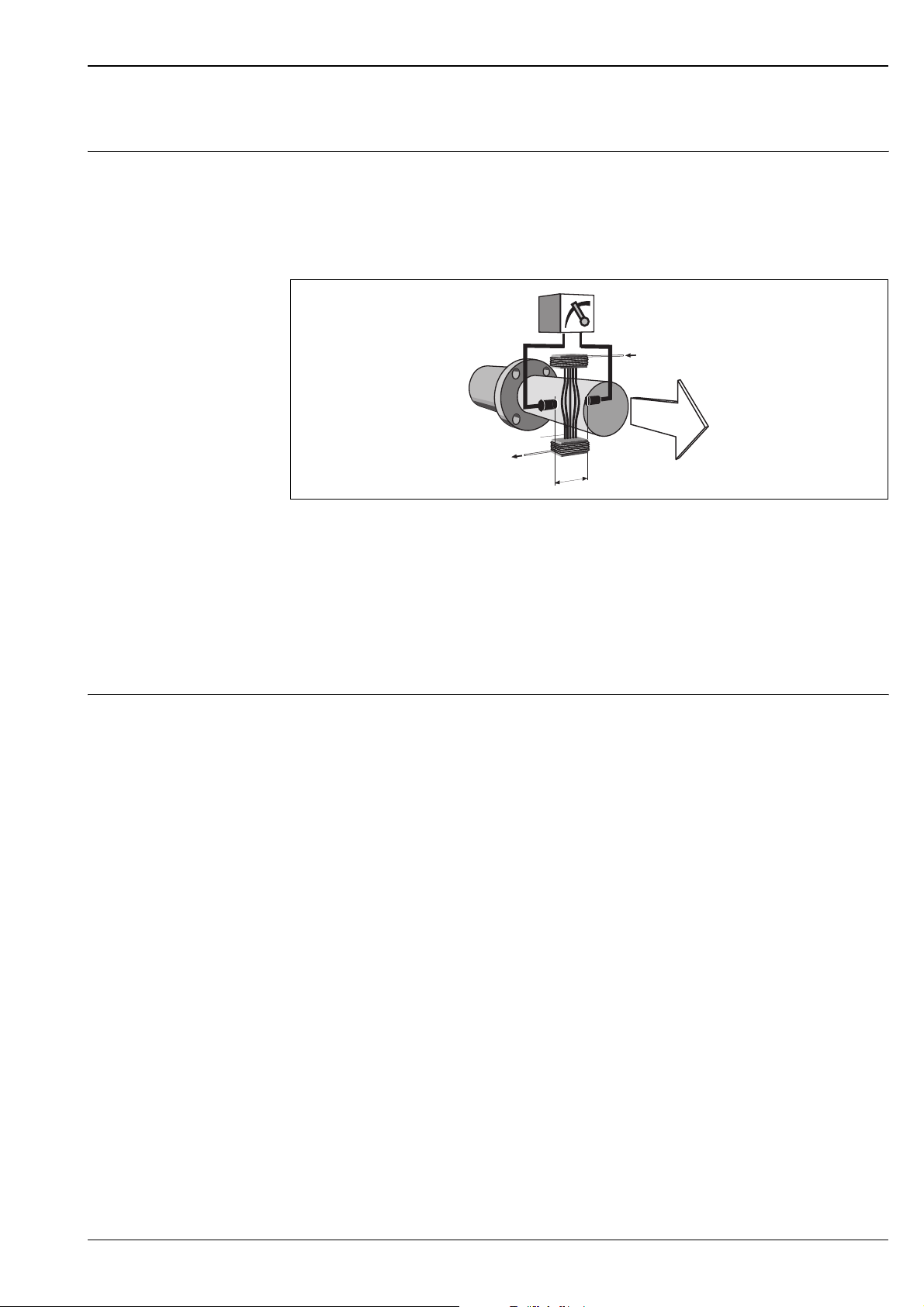
Measuring principle Following Faraday's law of magnetic induction, a voltage is induced in a conductor moving through a magnetic
field.
In the electromagnetic measuring principle, the flowing medium is the moving conductor.
The voltage induced is proportional to the flow velocity and is supplied to the amplifier by means
of two measuring electrodes. The flow volume is calculated by means of the pipe cross-sectional area.
The DC magnetic field is created through a switched direct current of alternating polarity.
Ue
I
V
B
I
L
A0003191
Ue = B · L · v
Q = A · v
Ue Induced voltage
B Magnetic induction (magnetic field)
L Electrode spacing
v Flow velocity
Q Volume flow
A Pipe cross-section
I Current strength
Measuring system The measuring system consists of a transmitter and a sensor.
Two versions are available:
• Compact version: Transmitter and sensor form a mechanical unit.
• Remote version: Sensor is mounted separate from the transmitter.
Transmitter:
• Promag 50 (user interface with push buttons for operation, two-line display, illuminated)
• Promag 53 ("Touch Control" without opening the housing, four-line display, unilluminated)
Sensor:
• Promag H (DN 2 to 100 / 1/12 to 4")
Endress+Hauser 3
Page 4

Input
Measured variable Flow velocity (proportional to induced voltage)
Measuring ranges Measuring ranges for liquids
Typically v = 0.01 to 10 m/s (0.03 to 33 ft/s) with the specified accuracy
Operable flow range Over 1000 : 1
Input signal Status input (auxiliary input)
• U = 3 to 30 V DC, R
• Configurable for: totalizer(s) reset, measured value suppression, error-message reset
Status input (auxiliary input) with PROFIBUS DP and MODBUS RS485
• U = 3 to 30 V DC, Ri = 3 kΩ, galvanically isolated
• Switching level: 3 to 30 V DC, independent of polarity
• Configurable for: totalizer(s) reset (MODBUS RS485 only), measured value suppression, error-message reset,
batching start/stop (optional), batch totalizer reset (optional)
Current input (only Promag 53)
• active/passive selectable, galvanically isolated, full scale value selectable, resolution: 3 μA,
temperature coefficient: typ. 0.005% o.r./°C (o.r. = of reading)
• active: 4 to 20 mA, R
• passive: 0/4 to 20 mA, R
= 5 kΩ, galvanically isolated
i
≤ 150 Ω, max. 24 V DC, short-circuit-proof
i
< 150 Ω, max. 30 V DC
i
Proline Promag 50H, 53H
Output
Output signal Promag 50
Current output
active/passive selectable, galvanically isolated, time constant selectable (0.01 to 100 s),
full scale value selectable, temperature coefficient: typ. 0.005% o.r./°C (o.r. = of reading), resolution: 0.5 μA
• active: 0/4 to 20 mA, RL < 700 Ω (HART: RL ≥ 250 Ω)
• passive: 4 to 20 mA, operating voltage V
Pulse/frequency output
passive, open collector, 30 V DC, 250 mA, galvanically isolated
• Frequency output: full scale frequency 2 to 1000 Hz (f
• Pulse output: pulse value and pulse polarity selectable, max. pulse width configurable (0.5 to 2000 ms)
PROFIBUS DP interface
• Transmission technology (Physical Layer): RS485 in accordance with ANSI/TIA/EIA-485-A: 1998,
galvanically isolated
• Profil version 3.0
• Data transmission rate: 9,6 kBaud to 12 MBaud
• Automatic data transmission rate recognition
• Function blocks: 1 × analog Input, 1 × totalizer
• Output data: volume flow, totalizer
• Input data: positive zero return (ON/OFF), totalizer control, value for local display
• Cyclic data transmission compatible with previous model Promag 33
• Bus address adjustable via miniature switches or local display (optional) at the measuring device
PROFIBUS PA interface
• Transmission technology (Physical Layer): IEC 61158-2 (MBP), galvanically isolated
• Profil version 3.0
• Current consumption: 11 mA
• Permissible supply voltage: 9 to 32 V
• Bus connection with integrated reverse polarity protection
• Error current FDE (Fault Disconnection Electronic): 0 mA
• Function blocks: 1 × analog input, 2 × totalizer
• Output data: volume flow, totalizer
• Input data: positive zero return (ON/OFF), control totalizer, value for local display
• Cyclic data transmission compatible with previous model Promag 33
• Bus address adjustable via miniature switches or local display (optional) at the measuring device
: 18 to 30 V DC, Ri ≥ 150 Ω
S
= 1250 Hz), on/off ratio 1:1, pulse width max. 10s
max
4 Endress+Hauser
Page 5

Proline Promag 50H, 53H
Promag 53
Current output
active/passive selectable, galvanically isolated, time constant selectable (0.01 to 100 s),
full scale value selectable, temperature coefficient: typ. 0.005% o.r./°C (o.r. = of reading), resolution: 0.5 μA
• active: 0/4 to 20 mA, R
< 700 Ω (HART: RL ≥ 250 Ω)
L
• passive: 4 to 20 mA, operating voltage VS: 18 to 30 V DC, Ri ≥ 150 Ω
Pulse/frequency output
active/passive selectable, galvanically isolated (Ex i version: only passive)
• active: 24 V DC, 25 mA (max. 250 mA during 20 ms), R
> 100 Ω
L
• passive: open collector, 30 V DC, 250 mA
• Frequency output: full scale frequency 2 to 10000 Hz (f
= 12500 Hz), EEx-ia: 2 to 5000 Hz;
max
on/off ratio 1:1, pulse width max. 10 s
• Pulse output: pulse value and pulse polarity selectable, max. pulse width configurable (0.05 to 2000 ms)
PROFIBUS DP interface
• Transmission technology (Physical Layer): RS485 in accordance with ANSI/TIA/EIA-485-A: 1998,
galvanically isolated
• Profil version 3.0
• Data transmission rate: 9,6 kBaud to 12 MBaud
• Automatic data transmission rate recognition
• Function blocks: 2 × analog Input, 3 × totalizer
• Output data: volume flow, calculated mass flow, totalizer 1 to 3
• Input data: positive zero return (ON/OFF), totalizer control, value for local display
• Cyclic data transmission compatible with previous model Promag 33
• Bus address adjustable via miniature switches or local display (optional) at the measuring device
• Available output combination → ä 8
PROFIBUS PA interface
• Transmission technology (Physical Layer): IEC 61158-2 (MBP), galvanically isolated
• Profil version 3.0
• Current consumption: 11 mA
• Permissible supply voltage: 9 to 32 V
• Bus connection with integrated reverse polarity protection
• Error current FDE (Fault Disconnection Electronic): 0 mA
• Function blocks: 2 × analog input, 3 × totalizer
• Output data: volume flow, calculated mass flow, totalizer 1 to 3
• Input data: positive zero return (ON/OFF), totalizer control, value for local display
• Cyclic data transmission compatible with previous model Promag 33
• Bus address adjustable via miniature switches or local display (optional) at the measuring device
MODBUS RS485 interface
• Transmission technology (Physical Layer): RS485 in accordance with ANSI/TIA/EIA-485-A: 1998,
galvanically isolated
• MODBUS device type: Slave
• Adress range: 1 to 247
• Bus address adjustable via miniature switches or local display (optional) at the measuring device
• Supported MODBUS function codes: 03, 04, 06, 08, 16, 23
• Broadcast: supported with the function codes 06, 16, 23
• Übertragungsmodus: RTU oder ASCII
• Supported baudrate: 1200, 2400, 4800, 9600, 19200, 38 400, 57600, 115200 Baud
• Response time:
– Direct data access = typically 25 to 50 ms
– Auto-scan buffer (data range) = typically 3 to 5 ms
• Available output combination → ä 8
Endress+Hauser 5
Page 6

Proline Promag 50H, 53H
FOUNDATION Fieldbus interface
• FOUNDATION Fieldbus H1
• Transmission technology (Physical Layer): IEC 61158-2 (MBP), galvanically isolated
• ITK version 5.01
• Current consumption: 12 mA
• Error current FDE (Fault Disconnection Electronic): 0 mA
• Bus connection with integrated reverse polarity protection
• Function blocks:
– 5 × Analog Input (execution time: 18 ms each)
– 1 × PID (25 ms)
– 1 × Digital Output (18 ms)
– 1 × Signal Characterizer (20 ms)
– 1 × Input Selector (20 ms)
– 1 × Arithmetic (20 ms)
– 1 × Integrator (18 ms)
• Output data: volume flow, calculated mass flow, temperature, totalizer 1 to 3
• Input data: positive zero return (ON/OFF), reset totalizer
• Link Master (LM) functionality is supported
Signal on alarm • Current output → failure response selectable (e.g. in accordance with NAMUR recommendation NE 43)
• Pulse/frequency output → failure response selectable
• Status output (Promag 50) → non-conductive by fault or power supply failure
• Relay output (Promag 53) → de-energized by fault or power supply failure
Load see "Output signal"
Low flow cutoff Switch points for low flow cutoff are selectable.
Galvanic isolation All circuits for inputs, outputs and power supply are galvanically isolated from each other.
Switching output Status output (Promag 50, Promag 53)
Open collector, max. 30 V DC / 250 mA, galvanically isolated.
Configurable for: error messages, Empty Pipe Detection (EPD), flow direction, limit values.
Relay outputs (Promag 53)
Normally closed (NC or break) or normally open (NO or make) contacts available
(default: relay 1 = NO, relay 2 = NC), max. 30 V / 0,5 A AC ; 60 V / 0,1 A DC, galvanically isolated.
Configurable for: error messages, Empty Pipe Detection (EPD), flow direction, limit values, batching contacts.
6 Endress+Hauser
Page 7
Proline Promag 50H, 53H
Power supply
Electrical connection, measuring unit
AB
d
g
b
d
g
b
a
HART*
–27
+26
–25
f f
+24
–23
+22
–21
+20
N (L-) 2
L1 (L+)1
d
e
c
b
a
PA(–)/FF(–)
PA(+)/FF(+)
N (L-)
L1 (L+)
C
d/(g)
b
(d)
PROFIBUS PA*
FOUNDATION Fieldbus*
27
26
–
25
+
24
–
23
+
22
–
21
+
20
2
1
a
d
e
c
b
PROFIBUS DP*
PROFIBUS DP**
MODBUS RS485**
N (L-)
L1 (L+)
27
26
–
25
+
24
–
23
+
22
–
21
+
20
2
1
A (RxD/TxD-N)
B (RxD/TxD-P)
d
e
g
c
–
+
–
+
–
+
N (L-)
L1 (L+)
27
26
25
24
23
22
21
20
2
1
A (RxD/TxD-N)
B (RxD/TxD-P)
f f
b
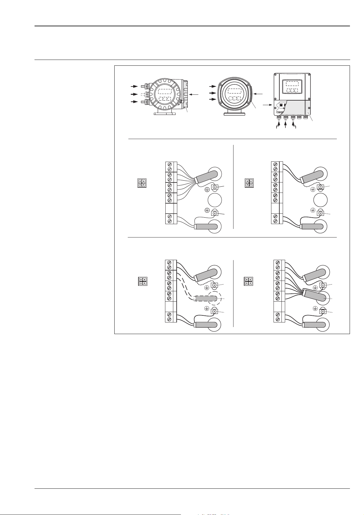
Connecting the transmitter, cable cross-section max. 2.5 mm2 (14 AWG)
A View A (field housing)
B View B (stainless steel field housing)
C View C (wall-mount housing)
*) fixed communication boards
**) flexible communication boards
a Connection compartment cover
b Cable for power supply: 85 to 260 V AC / 20 to 55 V AC / 16 to 62 V DC
- Terminal No. 1: L1 for AC, L+ for DC
- Terminal No. 2: N for AC, L– for DC
c Ground terminal for protective conductor
d Signal cable: see "Electrical connection, terminal assignment" → ä 8
Fieldbus cable:
- Terminal No. 26: DP (B) / PA + / FF + / MODBUS RS485 (B) / (PA, FF: with polarity protection)
- Terminal No. 27: DP (A) / PA – / FF – / MODBUS RS485 (A) / (PA, FF: with polarity protection)
e Ground terminal for signal cable shield / Fieldbus cable / RS485 line
f Service adapter for connecting service interface FXA193 (Fieldcheck, FieldCare)
g Signal cable: see "Electrical connection, terminal assignment" → ä 8
Cable for external termination (only for PROFIBUS DP with fixed assignment communication board):
- Terminal No. 24: +5 V
- Terminal No. 25: DGND
d
e
g
c
b
A0002441
Endress+Hauser 7
Page 8
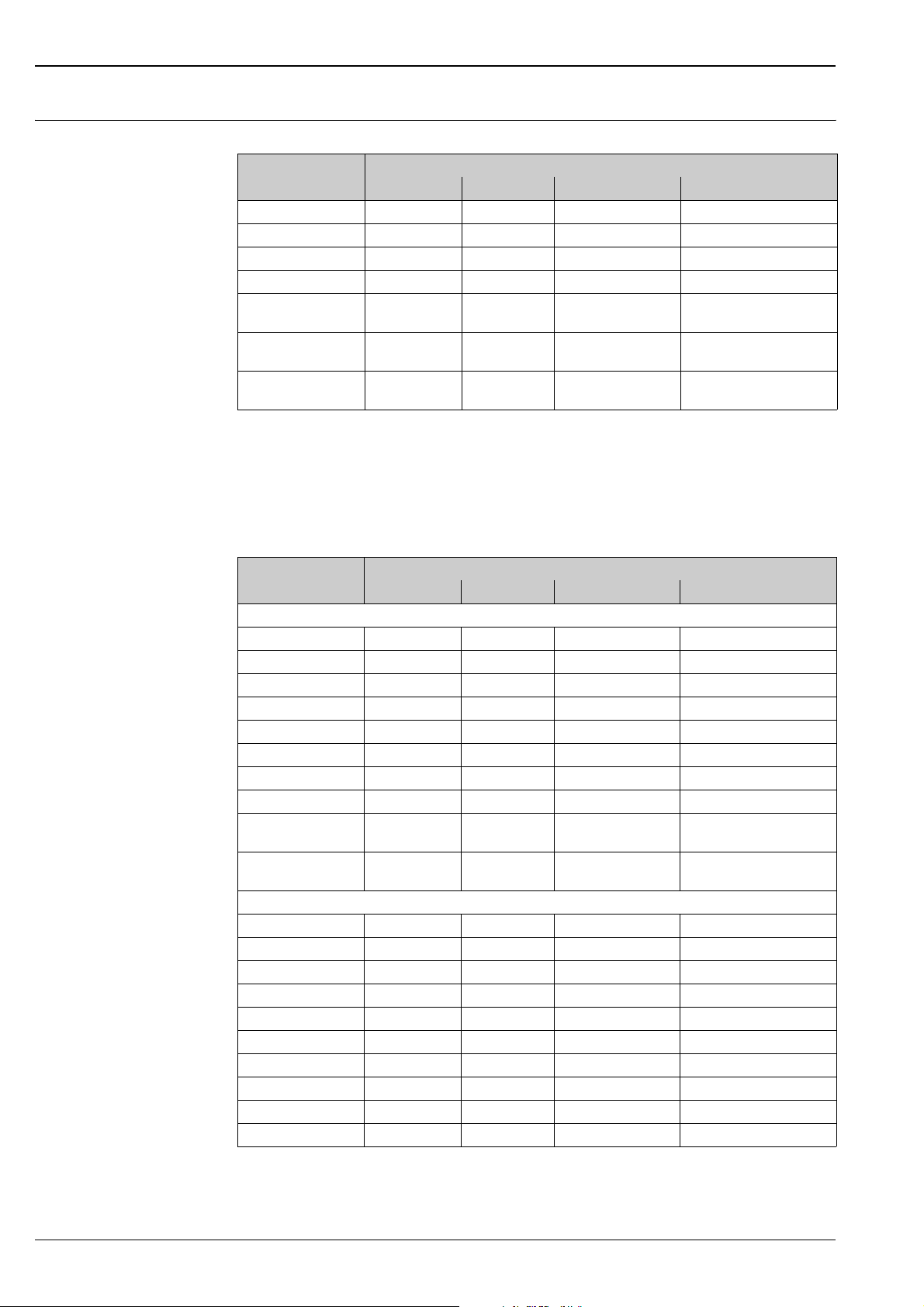
Proline Promag 50H, 53H
Electrical connection, terminal assignment
Terminal assignment, Promag 50
Order variant Terminal No. (inputs/outputs)
20 (+) / 21 (–) 22 (+) / 23 (–) 24 (+) / 25 (–) 26 (+) / 27 (–)
50***-***********W – – – Current output HART
50***-***********A – – Frequency output Current output HART
50***-***********D Status input Status output Frequency output Current output HART
50***-***********H – – – PROFIBUS PA
50***-***********J – – +5 V (external
termination)
50***-***********S – – Frequency output,
Ex i, passive
50***-***********T – – Frequency output,
Ex i, passive
Ground terminal → ä 7
PROFIBUS DP
Current output, Ex i,
passive, HART
Current output, Ex i,
passive, HART
Terminal assignment, Promag 53
The inputs and outputs on the communication board can be either permanently assigned or variable, depending
on the version ordered (see table). Replacements for modules which are defective or which have to be replaced
can be ordered as accessories.
Order variant Terminal No. (inputs/outputs)
20 (+) / 21 (–) 22 (+) / 23 (–) 24 (+) / 25 (–) 26 (+) / 27 (–)
Fixed communication boards (fixed assignment)
53***-***********A – – Frequency output Current output HART
53***-***********B Relay output 2 Relay output 1 Frequency output Current output HART
53***-***********F – – – PROFIBUS PA, Ex i
53***-***********G – – – FOUNDATION Fieldbus, Ex i
53***-***********H – – – PROFIBUS PA
53***-***********J – – – PROFIBUS DP
53***-***********K – – – FOUNDATION Fieldbus
53***-***********Q – – Status input MODBUS RS485
53***-***********S – – Frequency output, Ex i Current output, Ex i,
passive, HART
53***-***********T – – Frequency output, Ex i Current output, Ex i,
passive, HART
Flexible communication boards
53***-***********C Relay output 2 Relay output 1 Frequency output Current output HART
53***-***********D Status input Relay output Frequency output Current output HART
53***-***********L Status input Relay output 2 Relay output 1 Current output HART
53***-***********M Status input Frequency output Frequency output Current output HART
53***-***********N Current output Frequency output Status input MODBUS RS485
53***-***********P Current output Frequency output Status input PROFIBUS DP
53***-***********V Relay output 2 Relay output 1 Status input PROFIBUS DP
53***-***********2 Relay output Current output Frequency output Current output HART
53***-***********4 Current input Relay output Frequency output Current output HART
53***-***********7 Relay output 2 Relay output 1 Status input MODBUS RS485
Ground terminal → ä 7
8 Endress+Hauser
Page 9
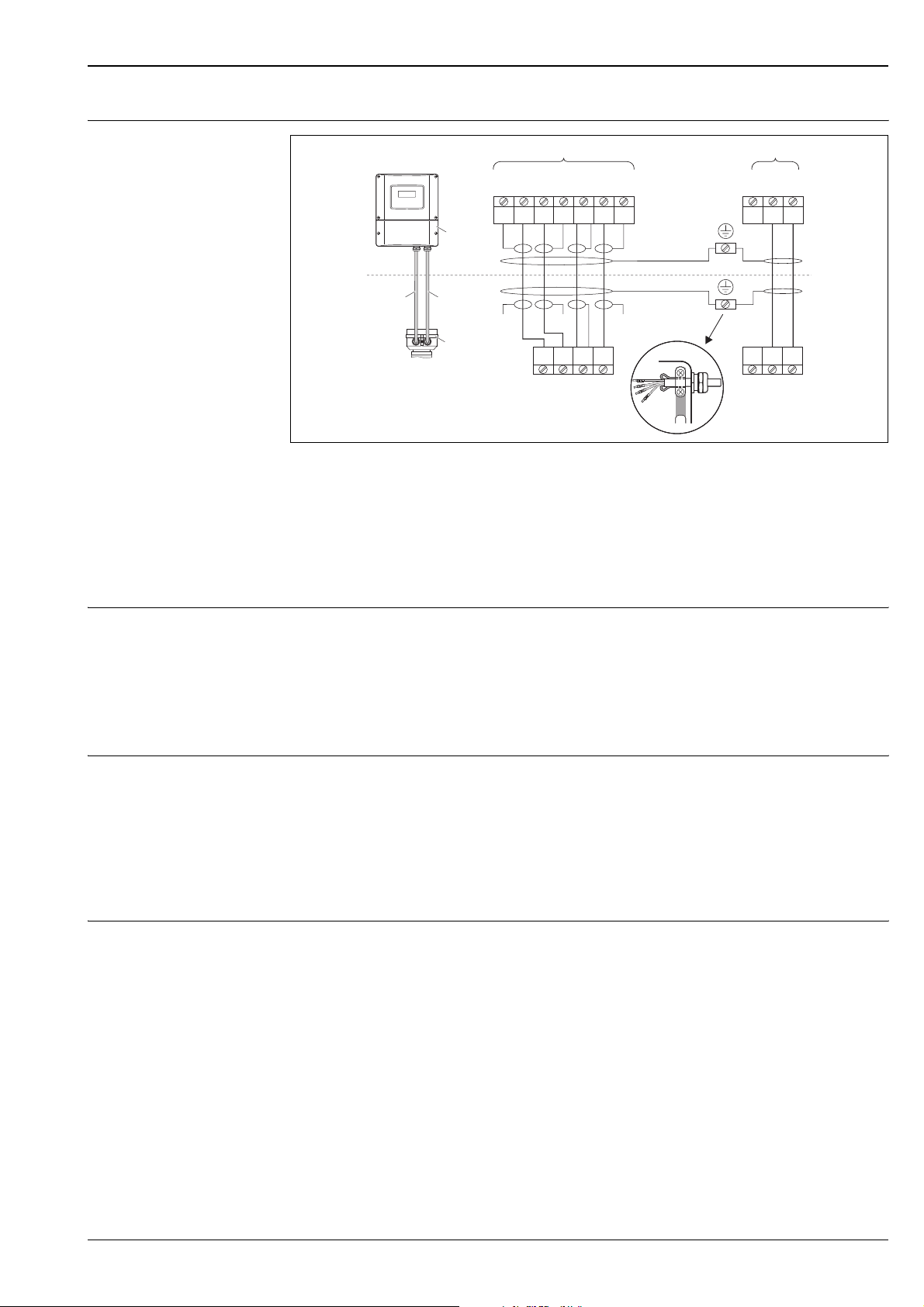
Proline Promag 50H, 53H
Electrical connection, remote version
S1
E1
E2
S2
GND
E
S
37 36
8
5
7
6
a
c d
n.c. n.c.
b
Connecting the remote version
a Wall-mount housing connection compartment
b Sensor connection housing cover
c Signal cable
d Coil current cable
n.c. Not connected, insulated cable shields
Terminal no. and cable colors: 6/5 = brown; 7/8 = white; 4 = green; 36/37 = yellow
4
n.c.
5
E1
37
7
4
E
E2
GND
dc
42 41
42 41
A0011747
Supply voltage (power supply) • 85 to 260 V AC, 45 to 65 Hz
• 20 to 55 V AC, 45 to 65 Hz
• 16 to 62 V DC
PROFIBUS PA and FOUNDATION Fieldbus
• Non-Ex: 9 to 32 V DC
• Ex i: 9 to 24 V DC
• Ex d: 9 to 32 V DC
Cable entry Power supply and signal cables (inputs/ outputs):
• Cable entry M20 × 1.5 (8 to 12 mm / 0.31 to 0.47")
• Sensor cable entry for armoured cables M20 × 1.5 (9.5 to 16 mm / 0.37 to 0.63")
• Thread for cable entries, ½" NPT, G ½"
Connecting cable for remote version:
• Cable entry M20 × 1.5 (8 to 12 mm / 0.31 to 0.47")
• Sensor cable entry for armoured cables M20 × 1.5 (9.5 to 16 mm / 0.37 to 0.63")
• Thread for cable entries, ½" NPT, G ½"
Remote version cable specifications
Coil cable
• 2 × 0.75 mm
2
(18 AWG) PVC cable with common, braided copper shield (∅ ∼ 7 mm / 0.28")
• Conductor resistance: ≤ 37 Ω/km (≤ 0.011 Ω/ft)
• Capacitance core/core, shield grounded: ≤ 120 pF/m (≤ 37 pF/ft)
• Operating temperature: –20 to +80 °C (–68 to +176 °F)
• Cable cross-section: max. 2.5 mm
2
(14 AWG)
• Test voltage for cable insulation: ≤ 1433 AC r.m.s. 50/60 Hz or ≥ 2026 V DC
Signal cable
• 3 × 0.38 mm2 (20 AWG) PVC cable with common, braided copper shield (∅ ∼ 7 mm / 0.28") and individual
shielded cores
• With empty pipe detection (EPD): 4 × 0.38 mm
braided copper shield (∅ ∼ 7 mm / 0.28") and individual shielded cores
• Conductor resistance: ≤ 50 Ω/km (≤ 0.015 Ω/ft)
• Capacitance core/shield: ≤ 420 pF/m (≤ 128 pF/ft)
• Operating temperature: –20 to +80 °C (–68 to +176 °F)
• Cable cross-section: max. 2.5 mm
2
(14 AWG)
2
(20 AWG) PVC cable with common,
Endress+Hauser 9
Page 10
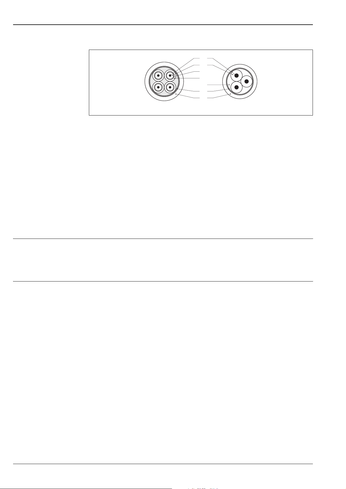
a Signal cable
b Coil current cable
1Core
2 Core insulation
3 Core shield
4 Core jacket
5 Core reinforcement
6 Cable shield
7 Outer jacket
Proline Promag 50H, 53H
1
2
3
4
5
6
7
ab
A0003194
Operation in zones of severe electrical interference
The measuring device complies with the general safety requirements in accordance with EN 61010 and
the EMC requirements of IEC/EN 61326 and NAMUR recommendation NE 21.
Caution!
"
Grounding is by means of the ground terminals provided for the purpose inside the connection housing.
Ensure that the stripped and twisted lengths of cable shield to the ground terminal are as short as possible.
Power consumption • AC: < 15 VA (incl. sensor)
• DC: < 15 W (incl. sensor)
Switch-on current:
• Max. 3 A (< 5 ms) for 260 V AC
• Max. 13.5 A (< 50 ms) for 24 V DC
Power supply failure Lasting min. ½ cycle frequency: EEPROM saves measuring system data
• EEPROM or T-DAT (Promag 53 only) retain the measuring system data in the event of a power supply failure
• S-DAT: exchangeable data storage chip which stores the data of the sensor (nominal diameter, serial number,
calibration factor, zero point etc.)
10 Endress+Hauser
Page 11
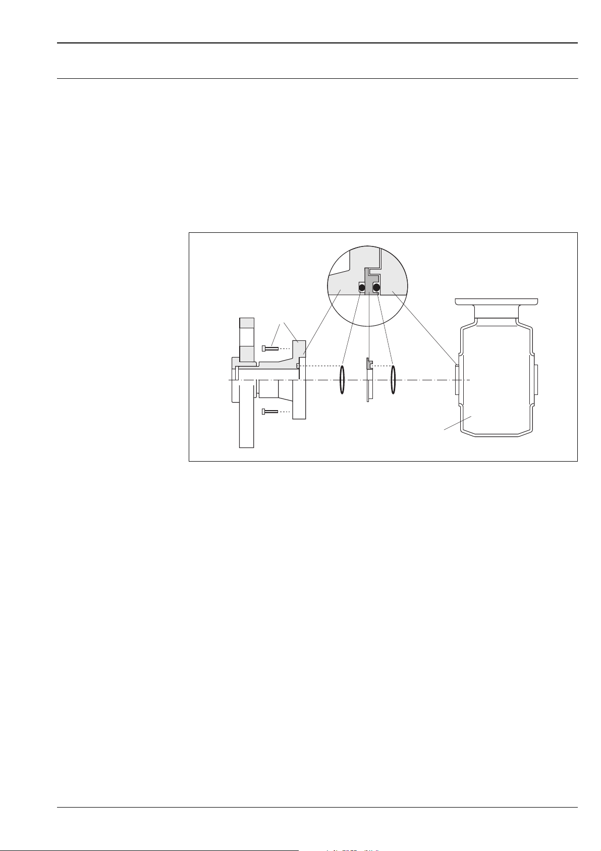
Proline Promag 50H, 53H
Potential equalization Perfect measurement is only ensured when the medium and the sensor have the same electrical potential.
Metal process connections
Potential matching usually takes place over the metallic process connection in contact with medium process
connections which are directly mounted on the measuring transmitter. This usually means that additional
potential matching measures are unnecessary.
Plastic process connections
For plastic process connections, potential matching must be ensured between sensor and medium using
additional ground rings. If these ground rings are missing, this can influence accuracy or destroy the measuring
transmitter through the electrochemical decomposition of electrodes.
1
1 Allen screw (process connection)
2 O-ring seals
3 Plastic washer (spacer) or ground ring
4Sensor
3
2
2
4
A0002651
When using ground rings, note the following points:
• Depending on the option ordered, plastic washers may be installed at the process connections instead of
ground rings. These plastic washers serve only as spacers and have no potential equalization function. In
addition, they provide a sealing function at the interface between the sensor and process connection.
For this reason, with process connections without ground rings, these plastic washers/seals must not be
removed, or must always be installed.
• Ground rings can be ordered separately from Endress+Hauser as an accessory.
Also make sure that the ground rings are compatible with the electrode material. Otherwise the danger exists
that the electrodes could be destroyed by electrochemical corrosion.
You can find material data on → ä 44.
• Ground rings, incl. seals, are mounted inside the process connection. This has no influence on the
installation length. You can find the dimensions of ground rings on → ä 35.
Endress+Hauser 11
Page 12
Performance characteristics
Proline Promag 50H, 53H
Reference operating conditions
As per DIN EN 29104 and VDI/VDE 2641:
• Fluid temperature: +28 °C ± 2 K (+82 °F ± 2 K)
• Ambient temperature: +22 °C ±2 K (+72 °F ± 2 K)
• Warm-up period: 30 minutes
Installation conditions:
• Inlet run > 10 × DN
• Outlet run > 5 × DN
• Sensor and transmitter grounded.
• The sensor is centered in the pipe.
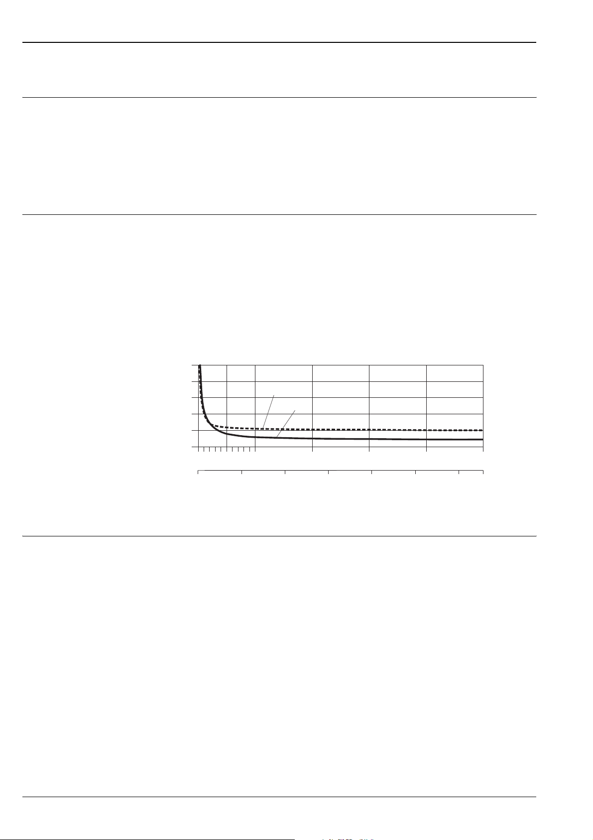
Maximum measured error Promag 50:
• Pulse output: ±0.5% o.r. ± 1 mm/s
optional: ±0.2% o.r. ± 2 mm/s
(o.r. = of reading)
• Current output: also typically ± 5 μA
Promag 53:
• Pulse output: ±0.2% o.r. ± 2 mm/s (o.r. = of reading)
• Current output: also typically ± 5 μA
Fluctuations in the supply voltage do not have any effect within the specified range.
[%]
2.5
2.0
1.5
1.0
0.5
0
Max. measured error in % of reading
0.5 %
0.2 %
0
1
2 4 6 8 10 [m/s]
v
5 10 15 20 25 30 32 [ft]0
A0005531
Repeatability Max. ±0.1% o.r. ± 0.5 mm/s (o.r. = of reading)
12 Endress+Hauser
Page 13
Proline Promag 50H, 53H
Operating conditions: Installations
Installation instructions Mounting location
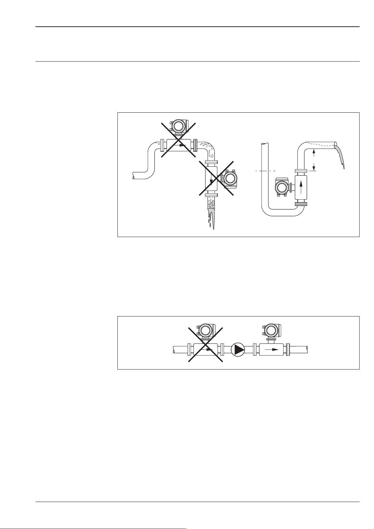
Entrained air or gas bubble formation in the measuring tube can result in an increase in measuring errors.
Avoid the following installation locations in the pipe:
• Highest point of a pipeline. Risk of air accumulating!
• Directly upstream from a free pipe outlet in a vertical pipeline.
h 2xDN³
A0011899
Mounting location
Installation of pumps
Sensors may not be installed on the pump suction side. This precaution is to avoid low pressure and the
consequent risk of damage to the lining of the measuring tube. Information on the pressure tightness of the
measuring tube lining → ä 19, Section "Pressure tightness".
Pulsation dampers may be needed when using piston pumps, piston diaphragm pumps or hose pumps.
Information on the shock and vibration resistance of the measuring system → ä 18, Section "Shock and
vibration resistance".
A0011900
Installation of pumps
Endress+Hauser 13
Page 14
Proline Promag 50H, 53H
Partially filled pipes
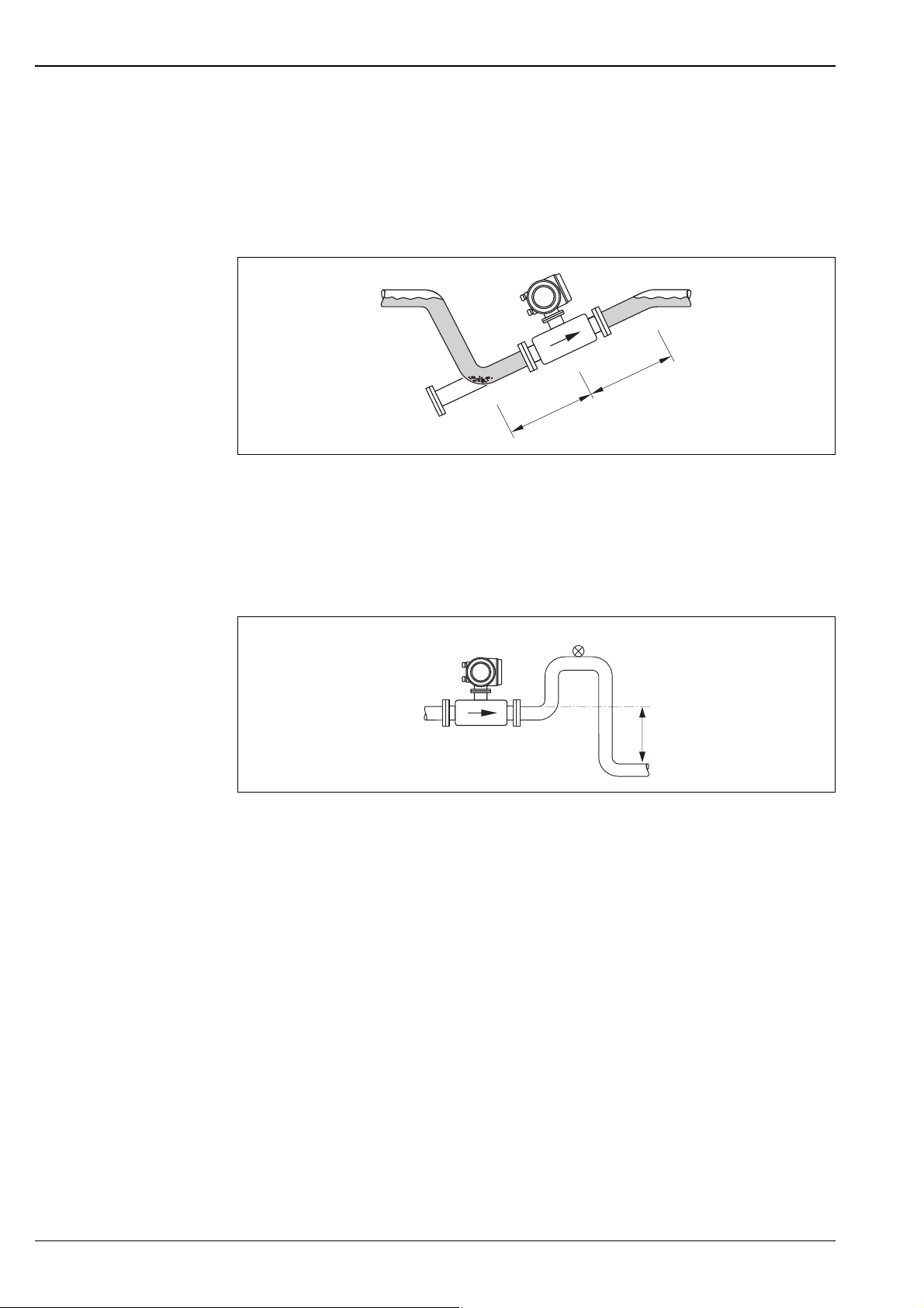
Partially filled pipes with gradients necessitate a drain-type configuration.
The empty pipe detection function (EPD) provides additional security in detecting empty or partially filled
pipes.
Caution!
"
Risk of solids accumulating. Do not install the sensor at the lowest point in the drain. It is advisable to install a
cleaning valve.
³ 2xDN
³ 5xDN
Installation with partially filled pipes
A0011901
Down pipes
Install a siphon or a vent valve downstream of the sensor in down pipes h ≥ 5 m (16.4 ft). This precaution is
to avoid low pressure and the consequent risk of damage to the lining of the measuring tube. This measure also
prevents the liquid current stopping in the pipe which could cause air locks. Information on the pressure
tightness of the measuring tube lining → ä 19, Section "Pressure tightness".
1
2
h
A0011902
Installation measures for vertical pipes
1 Vent valve
2Pipe siphon
h Length of the down pipe
14 Endress+Hauser
Page 15
Proline Promag 50H, 53H
Orientation
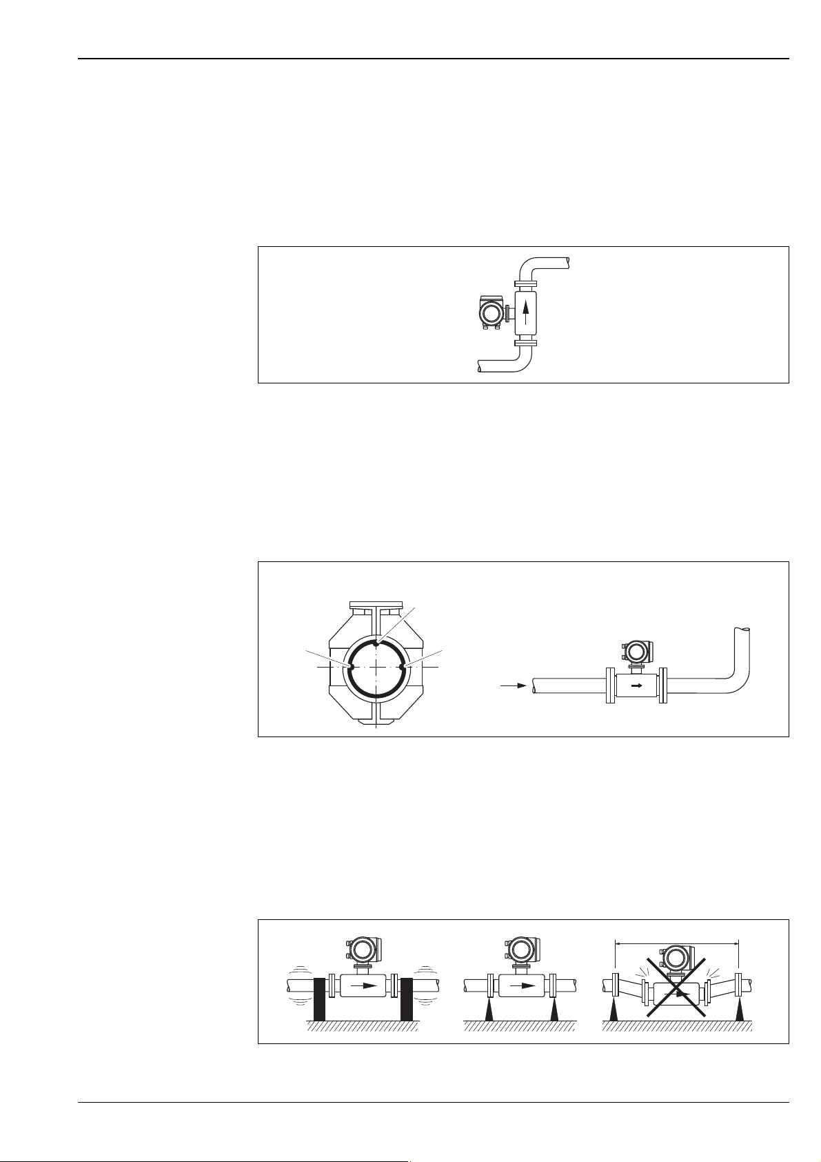
An optimum orientation helps avoid gas and air accumulations and deposits in the measuring tube. However,
the measuring device also offers the additional function of empty pipe detection (EPD) for detecting partially
filled measuring tubes or if outgassing fluids or fluctuating operating pressures are present.
Vertical orientation
This is the ideal orientation for self-emptying piping systems and for use in conjunction with empty pipe
detection.
Vertical orientation
Horizontal orientation
The measuring electrode axis should be horizontal. This prevents brief insulation of the two measuring
electrodes by entrained air bubbles.
Caution!
"
Empty pipe detection only works correctly with horizontal orientation if the transmitter housing is facing
upwards. Otherwise there is no guarantee that empty pipe detection will respond if the measuring tube is only
partially filled or empty.
A0011903
A
1
22
A
Horizontal orientation
1 EPD electrode for empty pipe detection (not for DN 2 to 15 / 1/12 to ½")
2 Measuring electrodes for signal detection
Vibrations
Secure the piping and the sensor if vibration is severe.
Caution!
"
If vibrations are too severe, we recommend the sensor and transmitter be mounted separately. Information on
the permitted shock and vibration resistance → ä 18, Section "Shock and vibration resistance".
L
A0012953
A0011906
Measures to prevent vibration of the measuring device
L > 10 m (33 ft)
Endress+Hauser 15
Page 16
Proline Promag 50H, 53H
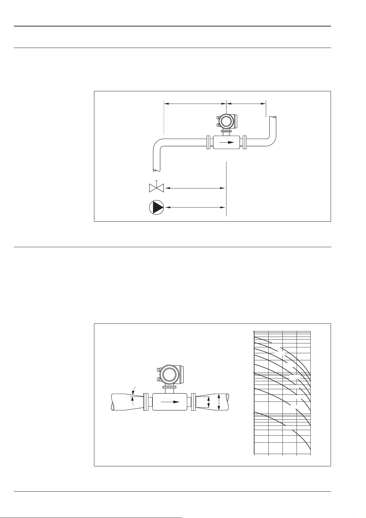
Inlet and outlet run If possible, install the sensor well clear of assemblies such as valves, T-pieces, elbows etc.
Note the following inlet and outlet runs to comply with measuring accuracy specifications:
• Inlet run: ≥ 5 × DN
• Outlet run: ≥ 2 × DN
5xDN³
Inlet and outlet run
³ 2xDN
A0011905
Adapters Suitable adapters to DIN EN 545 (double-flange reducers) can be used to install the sensor in larger-diameter
pipes. The resultant increase in the rate of flow improves measuring accuracy with very slow-moving fluids.
The nomogram shown here can be used to calculate the pressure loss caused by reducers and expanders.
!
Note!
The nomogram only applies to liquids of viscosity similar to water.
1. Calculate the ratio of the diameters d/D.
2. From the nomogram read off the pressure loss as a function of flow velocity (downstream from the
reduction) and the d/D ratio.
100
[mbar]
8 m/s
7 m/s
6 m/s
max. 8°
Pressure loss due to adapters
10
d
D
1
0.5
d/D
0.6 0.7 0.8 0.9
5 m/s
4 m/s
3 m/s
2 m/s
1 m/s
A0011907
16 Endress+Hauser
Page 17
Proline Promag 50H, 53H
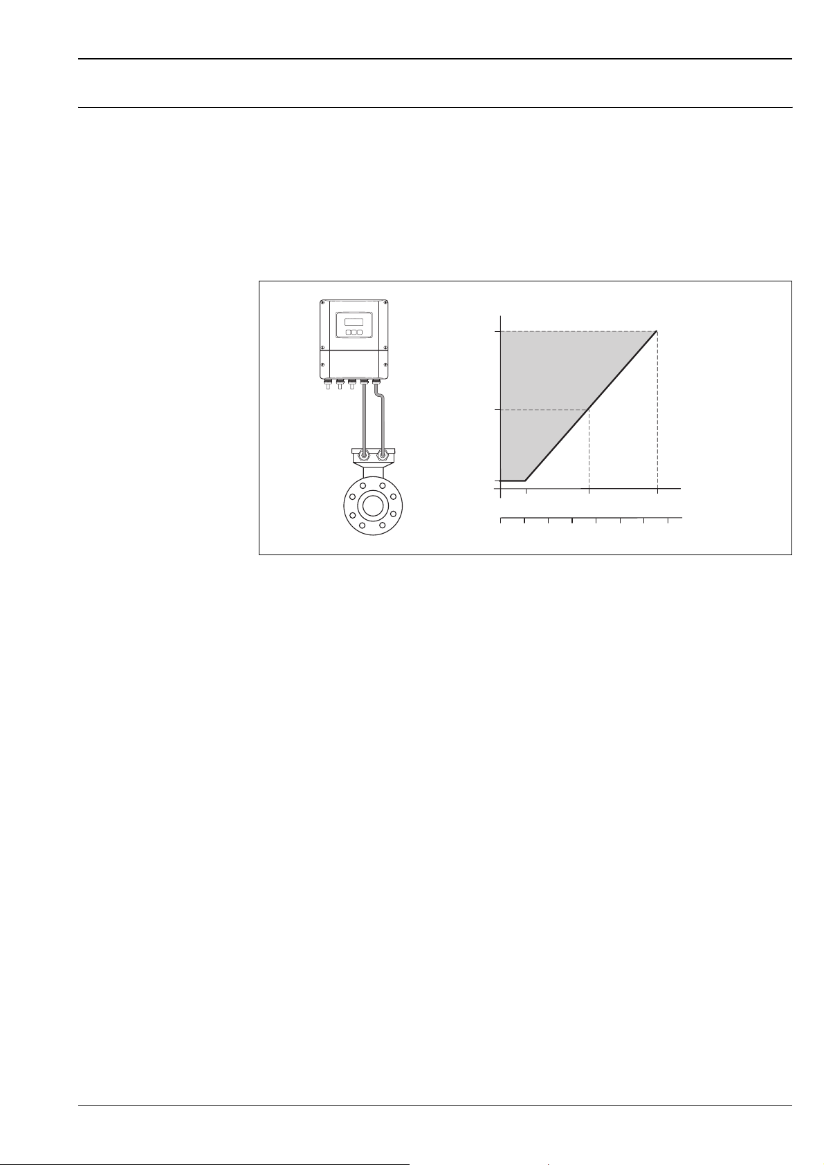
Length of connecting cable When mounting the remote version, please note the following to achieve correct measuring results:
• Fix cable run or lay in armored conduit. Cable movements can falsify the measuring signal especially in the
case of low fluid conductivities.
• Route the cable well clear of electrical machines and switching elements.
• If necessary, ensure potential equalization between sensor and transmitter.
• The permitted cable length L
20 μS/cm is required for measuring demineralized water.
• When the empty pipe detection function is switched on (EPD),
the maximum connecting cable length is 10 m (33 ft).
is determined by the fluid conductivity. A minimum conductivity of
max
[µS/cm]
200
L
max
Permitted length of connecting cable for remote version
Area marked in gray = permitted range; L
100
5
= length of connecting cable in [m] ([ft]); fluid conductivity in [μS/cm]
max
10 100 200
200 6000
400
[m][m]
[ft]
L
max
A0010734
Endress+Hauser 17
Page 18

Proline Promag 50H, 53H
Operating conditions: Environment
Ambient temperature range Transmitter
• Standard: –20 to +60 °C (–4 to +140 °F)
• Optional: –40 to +60 °C (–40 to +140 °F)
!
Storage temperature The storage temperature corresponds to the operating temperature range of the measuring transmitter and the
Note!
At ambient temperatures below –20 °C (–4 °F)the readability of the display may be impaired.
Sensor
• –40 to +60 °C (–40 to +140 °F)
Caution!
"
The permitted temperature range of the measuring tube lining may not be undershot or overshot
(→ ä 19, Section "Medium temperature range").
Please note the following points:
• Install the device in a shady location. Avoid direct sunlight, particularly in warm climatic regions.
• The transmitter must be mounted separate from the sensor if both the ambient and fluid temperatures are
high.
appropriate measuring sensors.
Caution!
"
• The measuring device must be protected against direct sunlight during storage in order to avoid unacceptably
high surface temperatures.
• A storage location must be selected where moisture does not collect in the measuring device. This will help
prevent fungus and bacteria infestation which can damage the liner.
• If protecting caps or protective covers are mounted, these must not be removed before mounting the device.
Degree of protection • Standard: IP 67 (NEMA 4X) for transmitter and sensor.
Shock and vibration resistance Acceleration up to 2 g following IEC 600 68-2-6
CIP cleaning possible
SIP cleaning possible
Electromagnetic compatibility (EMC)
• As per IEC/EN 61326 and NAMUR recommendation NE 21
• Emission: to limit value for industry EN 55011
18 Endress+Hauser
Page 19
Proline Promag 50H, 53H
Operating conditions: Process
Medium temperature range The permissible medium temperature depends on the sensor and the sealing material:
Sensor:
• DN 2 to 100 (1/12 to 4"): –20 to +150 °C (–4 to +302 °F)
Seals:
• EPDM: –20 to +150 °C (–4 to 302 °F)
• Viton: –20 to +150 °C (–4 to 302 °F)
• Silicone: –20 to +150 °C (–4 to 302 °F)
• Kalrez: –20 to +150 °C (–4 to 302 °F)
Conductivity The minimum conductivity is:
• ≥ 5 μS/cm for fluids generally
• ≥ 20 μS/cm for demineralized water
!
Note!
In the remote version, the necessary minimum conductivity also depends on the cable length
(→ ä 17, Section "Length of connecting cable").
Medium pressure range (nominal pressure)
The permitted nominal pressure depends on the process connection and the seal:
• 40 bar (580 psi):
– flange EN 1092-1 (DIN 2501)
– weld socket for DIN EN ISO 1127 pipes and ODT (with O-ring seal)
• 16 bar (232 psi): all other process connections
Pressure tightness Measuring tube lining: PFA
Nominal diameter Limit values for abs. pressure [mbar] ([psi]) at fluid temperatures:
[mm] [inch] 25 °C
(77 °F)
2 to 1001/12 to 4"000000
80 °C
(176 °F)
100 °C
(212 °F)
130 °C
(266 °F)
150 °C
(302 °F)
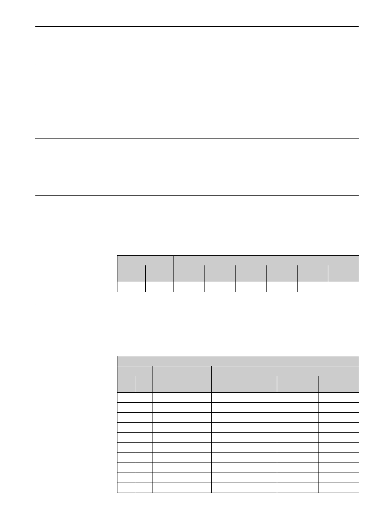
Limiting flow The diameter of the pipe and the flow rate determine the nominal diameter of the sensor.
The optimum flow velocity is between 2 to 3 m/s (6.5 to 9.8 ft/s). The velocity of flow (v), moreover, has to
be matched to the physical properties of the fluid:
• v < 2 m/s (6.5 ft/s): for small conductivities
• v > 2 m/s (6.5 ft/s): for fluids causing build-up such as high-fat milk etc.
Flow characteristic values (SI units)
Diameter Recommended flow rate Factory settings
Min./max. full scale value
[mm] [inch]
2 1/12" 0.06 to 1.8 dm
41/8" 0.25 to 7dm
83/8" 1 to 30dm
15 ½" 4 to 100 dm
25 1" 9 to 300 dm
40 1½" 25 to 700 dm
50 2" 35 to 1100 dm
65 – 60 to 2000 dm
80 3" 90 to 3000 dm
100 4" 145 to 4700 dm3/min 1200 dm3/min 10.0 dm
(v ~ 0.3 or 10 m/s)
Full scale value, current output
(v ~ 2.5 m/s)
3
/min 0.5 dm3/min 0.005 dm
3
/min 2 dm3/min 0.025 dm
3
/min 8 dm3/min 0.10 dm
3
/min 25 dm3/min 0.20 dm
3
/min 75 dm3/min 0.50 dm
3
/min 200 dm3/min 1.50 dm
3
/min 300 dm3/min 2.50 dm
3
/min 500 dm3/min 5.00 dm
3
/min 750 dm3/min 5.00 dm
Pulse value
(~ 2 pulses/s)
Low flow cut off
(v ~ 0.04 m/s)
3
0.01 dm3/min
3
0.05 dm3/min
3
3
3
1.00 dm3/min
3
3.00 dm3/min
3
5.00 dm3/min
3
8.00 dm3/min
3
12.0 dm3/min
3
20.0 dm3/min
180 °C
(356 °F)
0.1 dm3/min
0.5 dm3/min
Endress+Hauser 19
Page 20
Proline Promag 50H, 53H
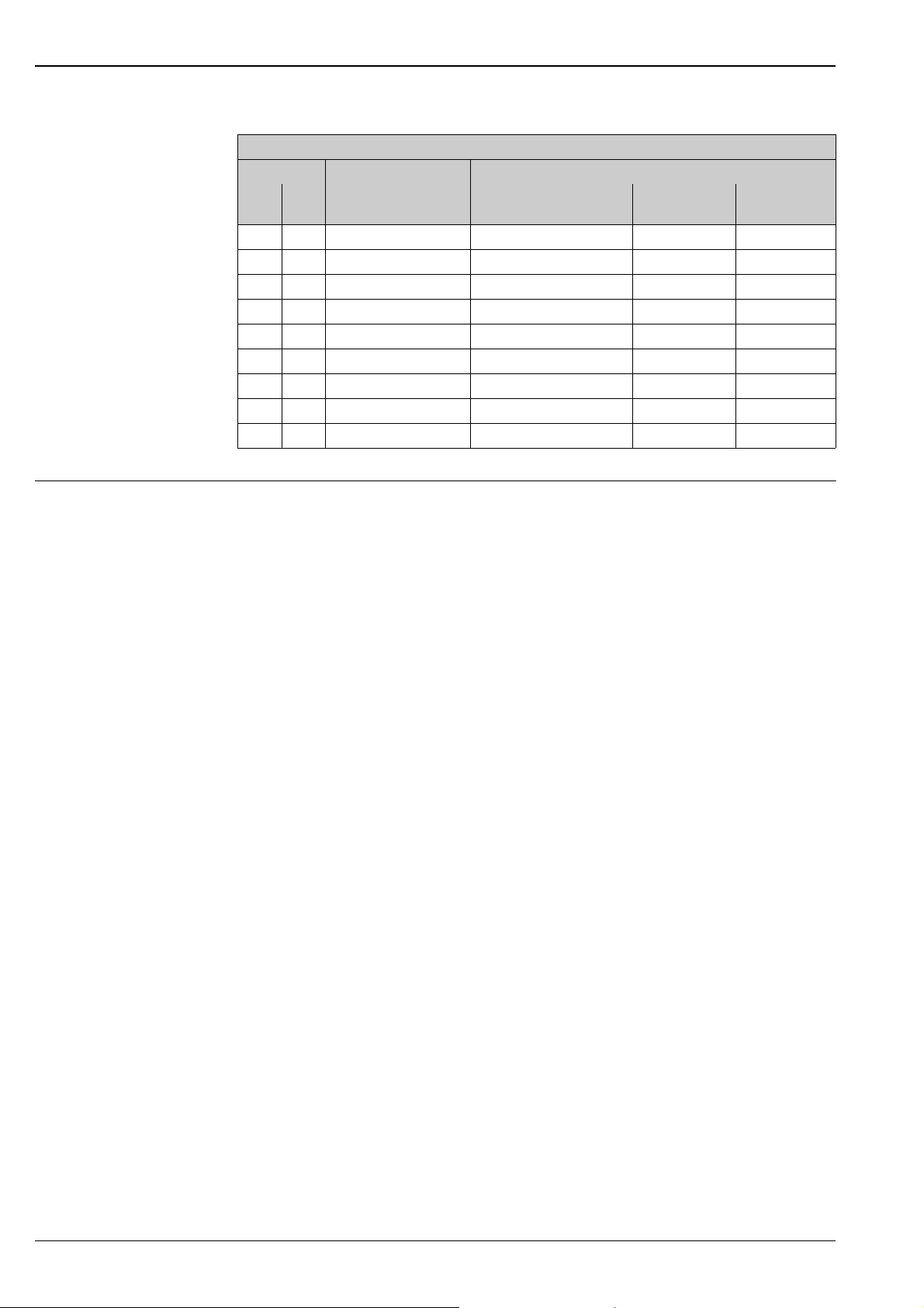
Flow characteristic values (US units)
Diameter Recommended flow rate Factory settings
Min./max. full scale value
[inch] [mm]
1/12" 2 0.015 to 0.5 gal/min 0.1 gal/min 0.001 gal 0.002 gal/min
1/8" 4 0.07 to 2 gal/min 0.5 gal/min 0.005 gal 0.008 gal/min
3/8" 8 0.25 to 8 gal/min 2 gal/min 0.02 gal 0.025 gal/min
½" 15 1.0 to 27 gal/min 6 gal/min 0.05 gal 0.10 gal/min
1" 25 2.5 to 80 gal/min 18 gal/min 0.20 gal 0.25 gal/min
1½" 40 7 to 190 gal/min 50 gal/min 0.50 gal 0.75 gal/min
2" 50 10 to 300 gal/min 75 gal/min 0.50 gal 1.25 gal/min
3" 80 24 to 800 gal/min 200 gal/min 2.00 gal 2.50 gal/min
4" 100 40 to 1250 gal/min 300 gal/min 2.00 gal 4.00 gal/min
(v ~ 0.3 or 10 m/s)
Pressure loss • With DN 8 to 100 (3/8 to 4") no pressure loss if the sensor is installed in a pipe with the same nominal
diameter.
• Pressure losses for configurations incorporating adapters according to DIN EN 545
(→ ä 16, Section "Adapters").
Full scale value, current output
(v ~ 2.5 m/s)
Pulse value
(~ 2 pulses/s)
Low flow cut off
(v ~ 0.04 m/s)
20 Endress+Hauser
Page 21
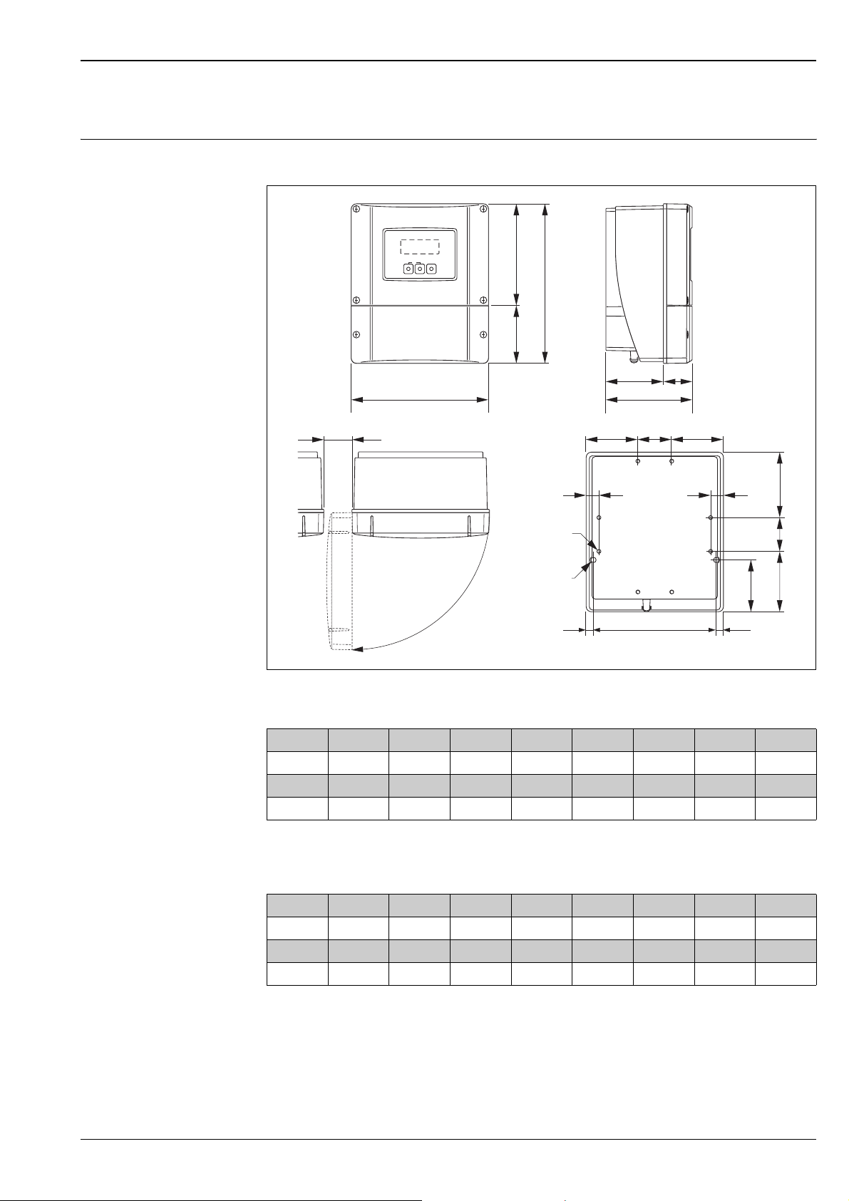
Proline Promag 50H, 53H
E
-
+
Mechanical construction
Design, dimensions Transmitter remote version, wall-mount housing (non Ex-zone and II3G/Zone 2)
Esc
D
B
C
F
G
A
H J
E
K
J
R
T
PP
Q
N
SS
M
L
O
A0001150
Dimensions (SI units)
A B C D E F G H J
215 250 90.5 159.5 135 90 45 > 50 81
K L M N O P Q R S
53 95 53 102 81.5 11.5 192 8 × M5 20
All dimensions in [mm]
Dimensions (US units)
A B C D E F G H J
8.46 9.84 3.56 6.27 5.31 3.54 1.77 > 1.97 3.18
K L M N O P Q R S
2.08 3.74 2.08 4.01 3.20 0.45 7.55 8 × M5 0.79
All dimensions in [inch]
Endress+Hauser 21
Page 22
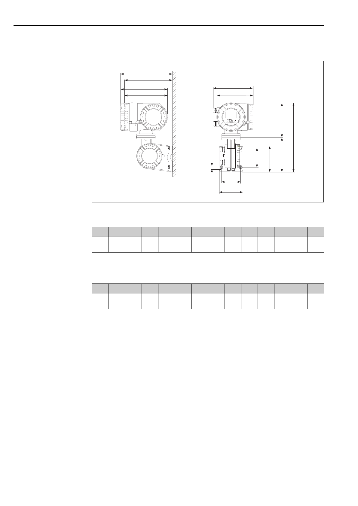
Transmitter remote version, connection housing (II2GD/Zone 1)
A
A*
B
B*
Nicht-eigensichere
Stromkreisedurch
IP40-Abdeckunggeschützt
Non-intrinsicallysafe
circuitsIp40 protected
Bouclesde courant
sanssécurité intrinsèque
protégéespar Ip40
C
D
r
S
e
p
t
n
a
u
n
n
t
u
h
n
c
i
g
n
e
n
N
f
f
ö
e
l
i
h
e
v
w
i
l
t
a
h
g
e
i
r
t
a
r
s
e
t
v
i
o
u
c
c
r
i
p
c
e
e
K
c
i
r
c
u
a
Esc
l
i
v
e
- +
E
n
s
o
o
i
N
l
s
u
s
n
i
t
e
e
e
r
p
a
a
p
s
p
o
a
u
l
’
v
r
i
r
Proline Promag 50H, 53H
K
e
e
p
c
o
i
v
t
s
e
r
a
t
r
i
e
g
h
t
w
h
i
l
e
E
M
J
L
K
F
G
H
Dimensions (SI units)
A A* B B* C D E Ø F G H J K L M
8.6
265 242 240 217 206 186 178
100 130 100 144 170 355
(M8)
All dimensions in [mm]
Dimensions (US units)
A A* B B* C D E Ø F G H J K L M
0.34
10.4 9.53 9.45 8.54 8.11 7.32 7.01
All dimensions in [inch]
3.94 5.12 3.94 5.67 6.69 14.0
(M8)
A0002128
22 Endress+Hauser
Page 23
Proline Promag 50H, 53H
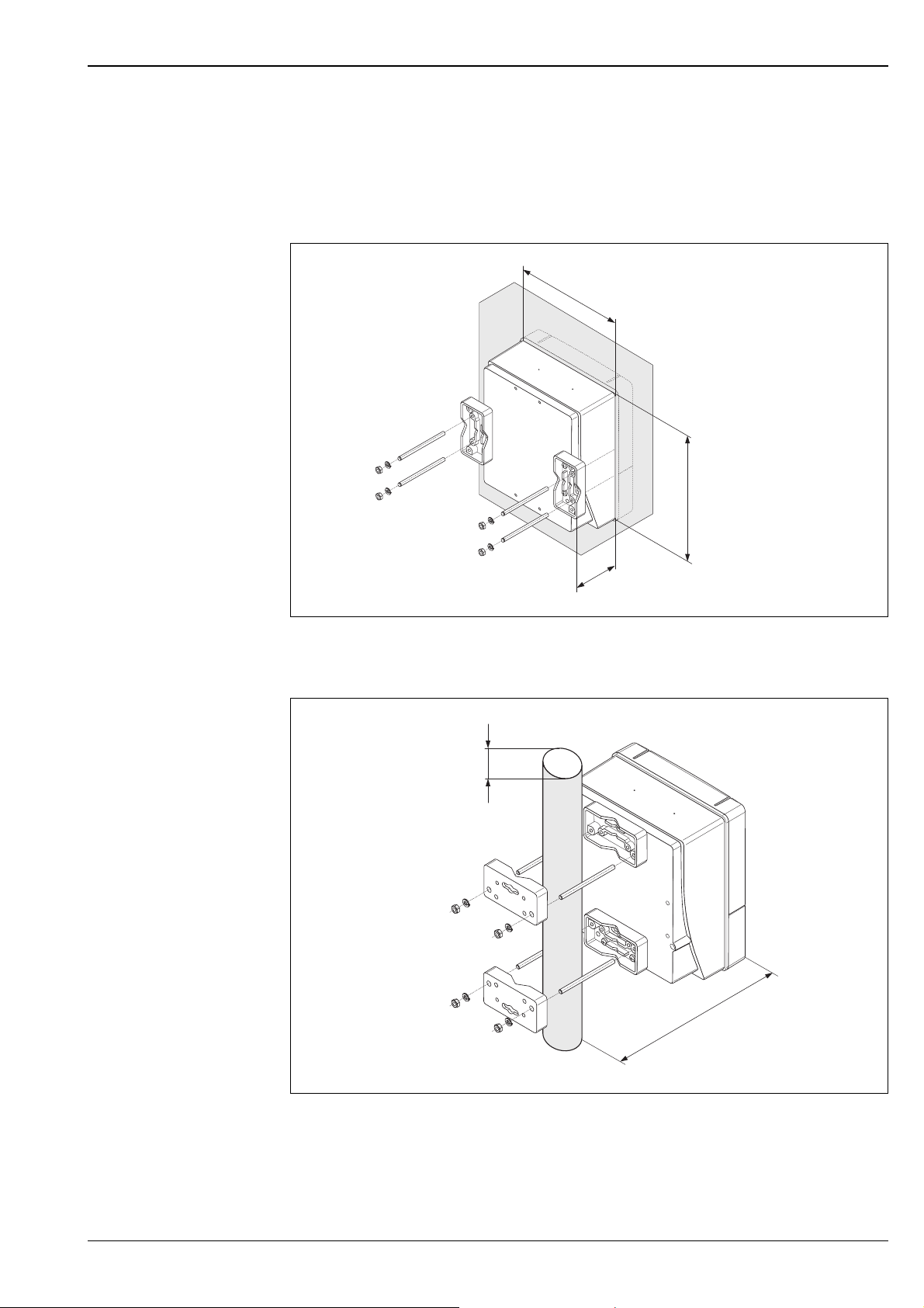
There is a separate mounting kit for the wall-mounted housing. It can be ordered from Endress+Hauser as an
accessory. The following installation variants are possible:
• Panel-mounted installation
• Pipe mounting
Installation in control panel
+0.5 (+0.019)
210 (8.27)
–0.5 (–0.019)
245 (9.65)
+0.5 (+0.019)
–0.5 (–0.019)
Pipe mounting
mm (inch)
(Ø 0.79…2.75)
~110(~4.33)
A0001131
Ø 20…70
~ ~ 6.1)155 (
mm (inch)
A0001132
Endress+Hauser 23
Page 24
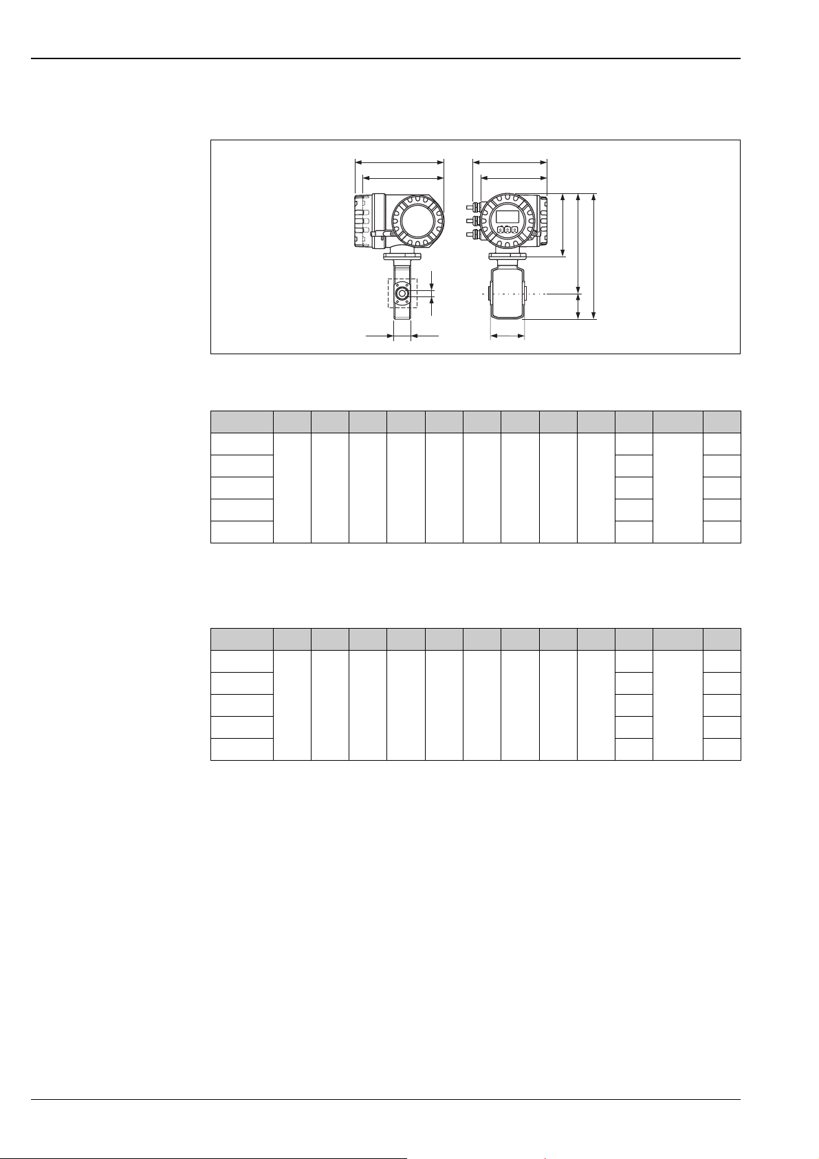
Compact version, aluminum field housing DN 2 to 25 (1/12 to 1")
Esc
E
-
+
Proline Promag 50H, 53H
A
B
C
D
E
G
H
X1
di
F
K
L
Dimensions in SI units
DN L A B C D E F G H K X1 di
2
4 43 4.5
8 43 9
86 227 207 187 168 160 55 252 307
15 43 16
25 56 26
Total length depends on the process connections.
All dimensions in [mm]
43
M6 × 4
A0005426
2.25
Dimensions in US units
DN L A B C D E F G H K X1 di
1/12"
1/8" 1.69 0.18
3/8" 1.69 0.35
3.39 8.94 8.15 7.36 6.61 6.30 2.17 9.92 12.1
½" 1.69 0.63
1" 2.20 0.89
Total length depends on the process connections.
All dimensions in [inch]
1.69
M6 × 4
0.09
24 Endress+Hauser
Page 25
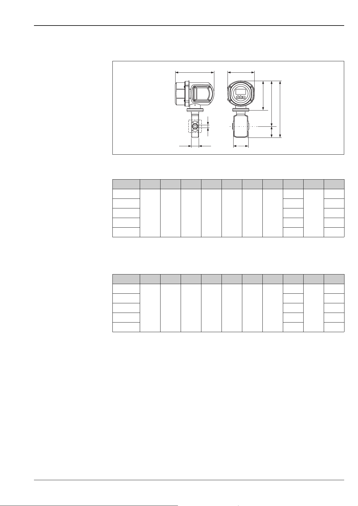
Proline Promag 50H, 53H
Esc
E
-
+
Compact version, stainless-steel field housing DN 2 to 25 (1/12 to 1")
A
B
C
E
F
X1
di
D
K
L
Dimensions in SI units
DN L A B C D E F K X1 di
2
4 43 4.5
8 43 9
86 225 153 168 55 261 316
15 43 16
25 56 26
Total length depends on the process connections.
All dimensions in [mm]
43
M6 × 4
A0005427
2.25
Dimensions in US units
DN L A B C D E F K X1 di
1/12"
1/8" 1.69 0.18
3/8" 1.69 0.35
3.39 8.86 6.02 6.61 2.17 10.3 12.4
½" 1.69 0.63
1" 2.20 0.89
Total length depends on the process connections.
All dimensions in [inch]
1.69
M6 × 4
0.09
Endress+Hauser 25
Page 26
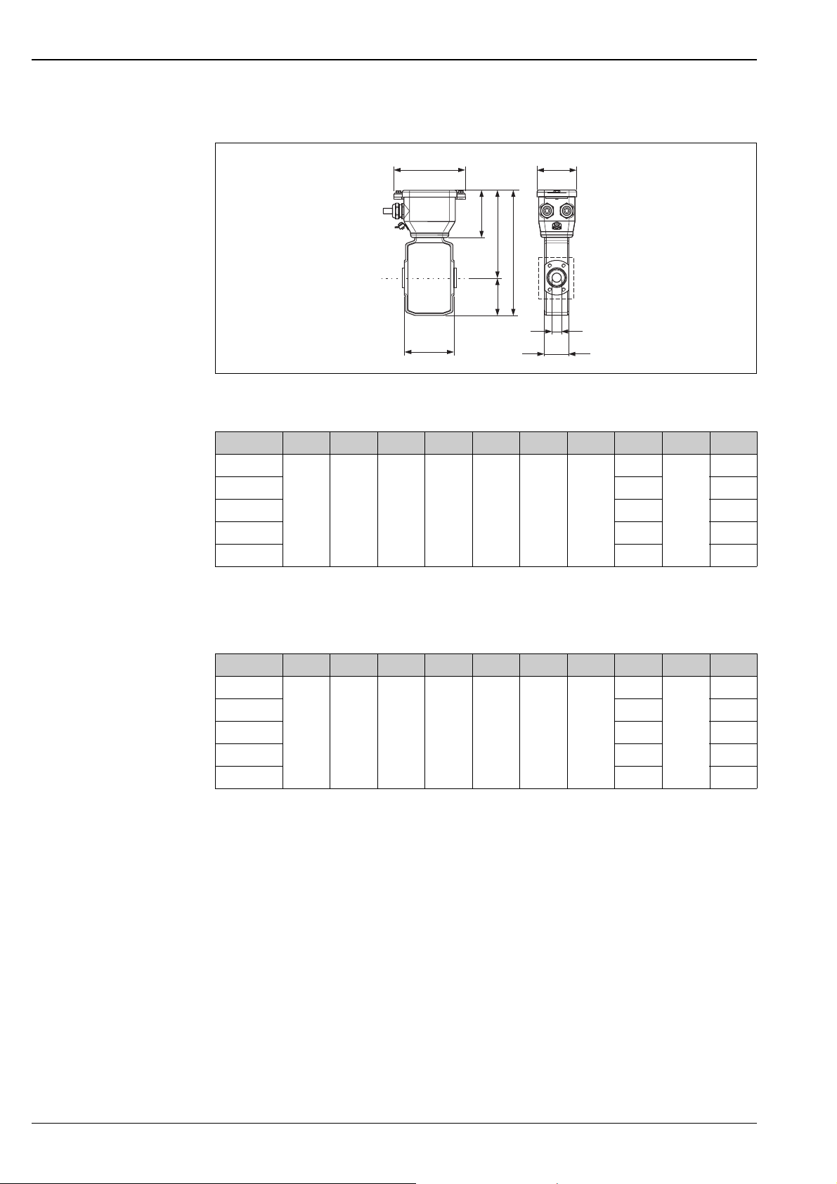
Sensor, remote version DN 2 to 25 (1/12 to 1")
Proline Promag 50H, 53H
A
C
E
D
L
B
F
X1
di
K
Dimensions in SI units
DN L A B C D E F K X1 di
2
4 43 4.5
8 43 9.0
15 43 16.0
25 56 26.0
Total length depends on the process connections.
All dimensions in [mm]
86 127 70 75 55 136 191
43
M6 × 4
A0005536
2.25
Dimensions in US units
DN L A B C D E F K X1 di
1/12"
1/8" 1.69 0.18
3/8" 1.69 0.35
½" 1.69 0.63
1" 2.20 0.89
Total length depends on the process connections.
All dimensions in [inch]
3.39 5.00 2.76 2.95 2.17 5.35 7.52
1.69
M6 × 4
0.09
26 Endress+Hauser
Page 27
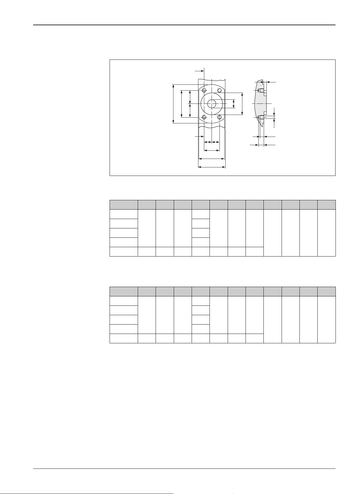
Proline Promag 50H, 53H
Sensor, front view (without process connections) DN 2 to 25 (1/12 to 1")
Z Z-Z
L
A
B
B/2 B/2
E
E
–
–
2
Z
2
E
F
G
D
C
M
K
H
A0008190
Dimensions in SI units
DN A B C D E F G H K L M
2
49
89
15 16
25 72 50.2 44 26 29 55 56
All dimensions in [mm]
62 41.6 34
9
24 42 43
8.5 6 4 M6
Dimensions in US units
DN A B C D E F G H K L M
1/12"
1/8" 0.35
3/8" 0.35
½" 0.63
1" 2.83 1.98 1.73 0.89 1.14 2.17 2.20
All dimensions in [inch]
2.44 1.64 1.34
0.35
0.94 1.65 1.69
0.33 0.24 0.16 M6
Endress+Hauser 27
Page 28
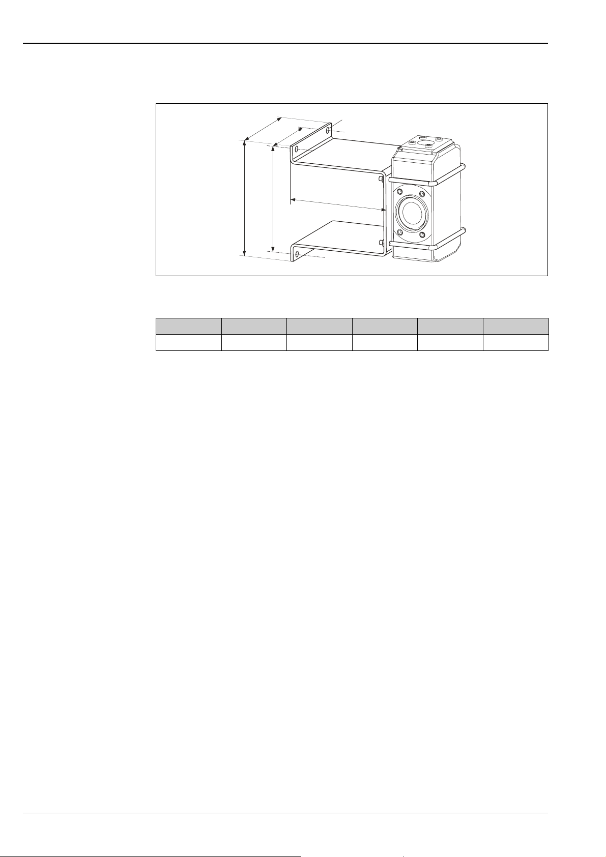
Sensor, wall mounting kit DN 2 to 25 (1/12 to 1")
Proline Promag 50H, 53H
E
B
F
A
D
C
Dimensions in mm (inch)
A B C Ø D E F
125 (4.92") 88 (3.46") 120 (4.72") 7 (0.28") 110 (4.33") 140 (5.51")
A0005537
28 Endress+Hauser
Page 29
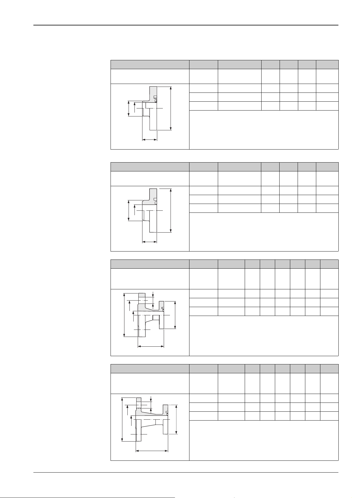
Proline Promag 50H, 53H
Process connections with O-ring seal (DN 2 to 25 / 1/12 to 1")
Weld socket for DIN Sensor Fits to di G L H × B
1.4404 / 316L
5*H**-B***********
G
di
HxB
L
A0005547
Weld socket for ODT/SMS Sensor Fits to di G L H × B
1.4404 / 316L
5*H**-C***********
G
di
HxB
DN
[mm]
Piping
DIN EN ISO 1127 [mm] [mm] [mm] [mm]
2 to 8 13.5 × 1.6 10.3 13.5 20.3 62 × 42
15 21.3 × 1.6 18.1 21.3 20.3 62 × 42
25 (DIN) 33.7 × 2.0 29.7 33.7 20.3 62 × 52
• Fitting length = (2 × L) + 86 mm
DN
[mm]
Piping ODT/SMS
[mm] [mm] [mm] [mm] [mm]
2 to 8 13.5 × 2.3 17.3 13.5 20.3 62 × 42
15 21.3 × 2.65 17.3 21.3 20.3 62 × 42
25 (DIN) 33.7 × 3.25 28.5 33.7 20.3 72 × 55
• Fitting length = (2 × L) + 86 mm
L
A0005548
Flange Sensor Fits to di G L LK M H × B
PN 40/EN 1092-1 (DIN 2501), Form B
1.4404 / 316L
5*H**-D***********
M
DN
[mm]
2 to 8 DN 15 17.3 95 56.2 65 14 62 × 42
1)
Flange
[mm] [mm] [mm] [mm] [mm] [mm] [mm]
15 DN 15 17.3 95 56.2 65 14 62 × 42
LK
G
di
HxB
25 (DIN) DN 25 28.5 115 56.2 85 14 72 × 55
1)
EN 1092-1 (DIN 2501)
• Fitting length = (2 × L) + 86 mm
• Fitting length to DVGW (200 mm)
L
A0005549
Flange Sensor Fits to di G L LK M H × B
Cl. 150/ ANSI B16.5
1.4404 / 316L
5*H**-E***********
M
DN
[mm]
2 to 8 ½" 15.7 89 66.0 60.5 15.7 62 × 42
Flange
ANSI B16.5
[inch] [mm] [mm] [mm] [mm] [mm] [mm]
15 ½" 16.0 89 66.0 60.5 15.7 62 × 42
LK
LK
G
di
25 (1" ANSI) 1" 26.7 108 71.8 79.2 15.7 72 × 55
HxB
• Fitting length = (2 × L) + 86 mm
L
A0005550
Endress+Hauser 29
Page 30
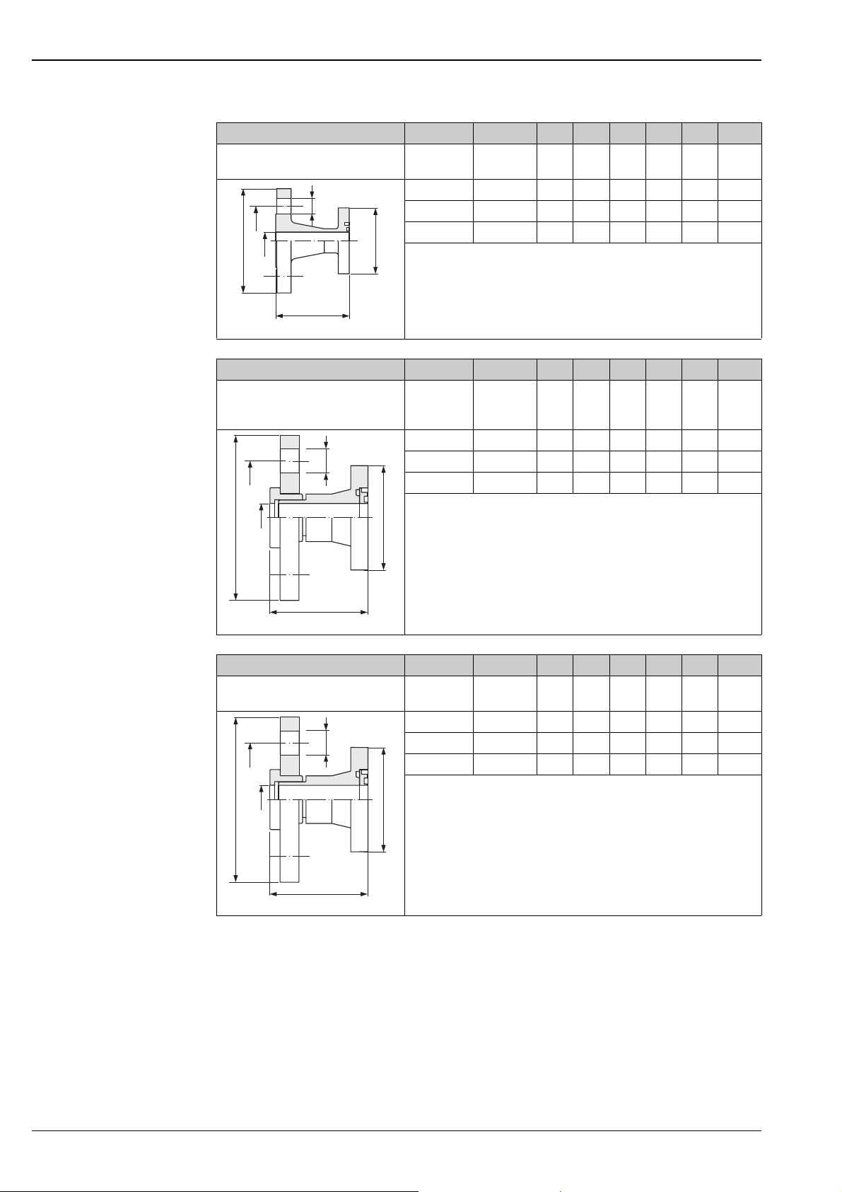
Proline Promag 50H, 53H
Flange Sensor Fits to di G L LK M H × B
20K / JIS B2220; 1.4404 / 316L
5*H**-F***********
M
LK
LK
G
di
HxB
L
A0005551
Flange Sensor Fits to di G L LK M H × B
PN 16 / EN 1092-1 (DIN 2501); PVDF
5*H**-G***********
M
LK
G
di
HxB
DN
[mm]
Flange
B2220 [mm] [mm] [mm] [mm] [mm] [mm]
2 to 8 ND 15 15 95 67 70 15 62 × 42
15 ND 15 16 95 67 70 15 62 × 42
25 (DIN) ND 25 26 125 67 90 19 72 × 55
• Fitting length = (2 × L) + 86 mm
DN
[mm]
Flange
EN 1092-1
[mm] [mm] [mm] [mm] [mm] [mm]
(DIN 2501)
2 to 8 DN 15 16 95 57 65 14 62 × 42
15 DN 15 16 95 57 65 14 62 × 42
25 (DIN) DN 25 27.2 115 57 85 14 72 × 55
• Fitting length = (2 × L) + 86 mm
• Fitting length to DVGW (200 mm)
• The requisite ground rings can be ordered as accessories
(Order No. DK5HR-****).
L
A0005567
Flange Sensor Fits to di G L LK M H × B
Cl. 150 / ANSI B16.5; PVDF
5*H**-H***********
M
DN
[mm]
Flange
ANSI B16.5 [mm] [mm] [mm] [mm] [mm] [mm]
2 to 8 ½" 16 95 57 60 16 62 × 42
15 ½" 16 95 57 60 16 62 × 42
LK
25 (DIN) 1" 27.2 115 57 79 16 72 × 55
• Fitting length = (2 × L) + 86 mm
G
di
• The requisite ground rings can be ordered as accessories
HxB
(Order No. DK5HR-****).
L
A0005567
30 Endress+Hauser
Page 31
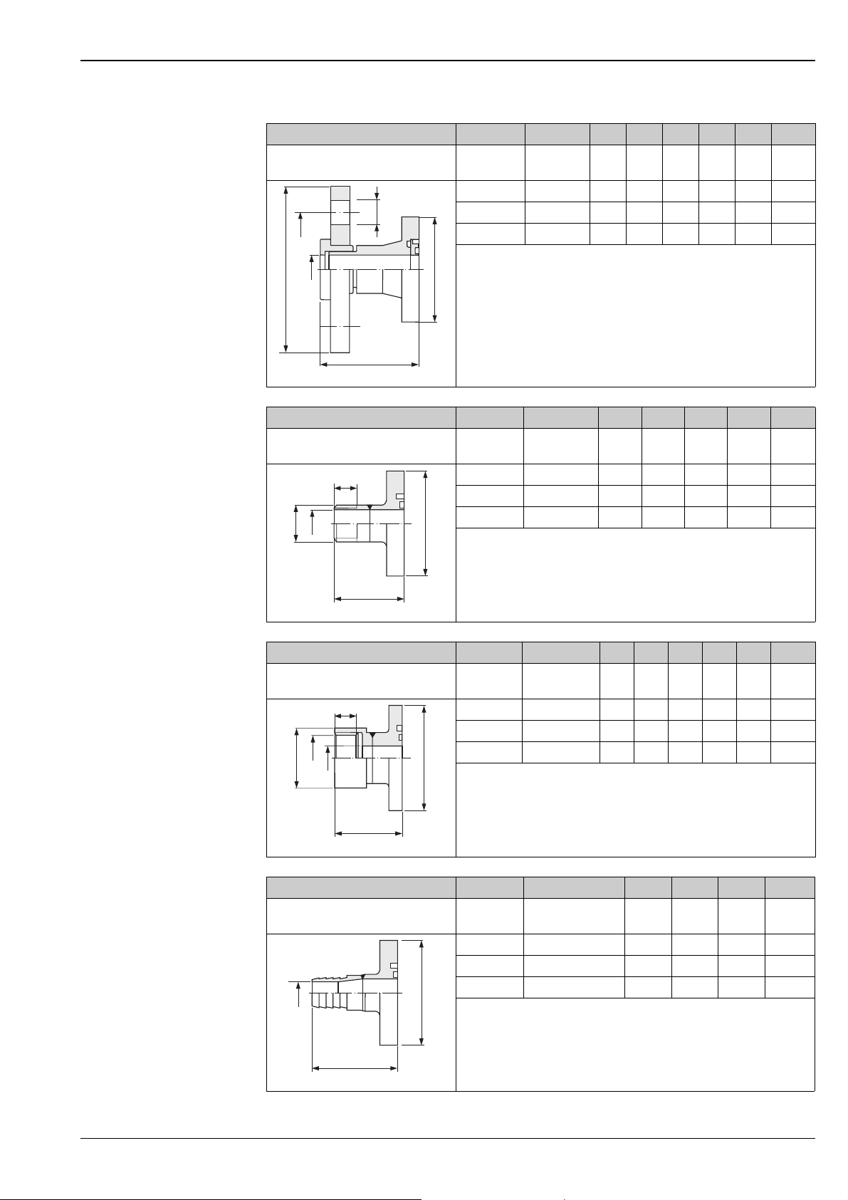
Proline Promag 50H, 53H
Flange Sensor Fits to di G L LK M H × B
10K / JIS B2220; PVDF
5*H**-J***********
M
DN
[mm]
Flange
B2220 [mm] [mm] [mm] [mm] [mm] [mm]
2 to 8 ND 15 16 95 57 70 15 62 × 42
15 ND 15 16 95 57 70 15 62 × 42
LK
25 (DIN) ND 25 27.2 125 57 90 19 72 × 55
• Fitting length = (2 × L) + 86 mm
G
di
• The requisite ground rings can be ordered as accessories
HxB
(Order No. DK5HR-****).
L
A0005567
External pipe thread Sensor Fits to di G L S H × B
ISO 228/ DIN 2999; 1.4404 / 316L
5*H**-K***********
S
DN
[mm]
Internal thread
[inch] [mm] [inch] [mm] [mm] [mm]
2 to 8 R 3/8" 10 3/8" 40 10.1 62 × 42
15 R ½" 16 ½" 40 13.2 62 × 42
G
di
25 (1" ANSI) R 1" 25 1" 42 16.5 72 × 55
HxB
• Fitting length = (2 × L) + 86 mm
L
A0005563
Internal pipe thread Sensor Fits to di G D L S H × B
ISO 228/ DIN 2999; 1.4404 / 316L
5*H**-L***********
S
DN
[mm]
External thread
[inch] [mm] [inch] [mm] [mm] [mm] [mm]
2 to 8 Rp 3/8" 9 3/8" 22 45 13 62 × 42
15 Rp ½" 16 ½" 27 45 14 62 × 42
G
D
di
25 (1" ANSI) Rp 1" 27.2 1" 40 51 17 72 × 55
HxB
• Fitting length = (2 × L) + 86 mm
L
A0005565
Hose connection Sensor Fits to di LW L H × B
1.4404 / 316L
5*H**-M/N/P***********
DN
[mm]
Inside diameter
[inch] [mm] [mm] [mm] [mm]
2 to 8 13 10.0 13 49 62 × 42
15 16 12.6 16 49 62 × 42
25 19 16.0 19 49 62 × 42
di
HxB
• Fitting length = (2 × L) + 86 mm
L
A0005562
Endress+Hauser 31
Page 32
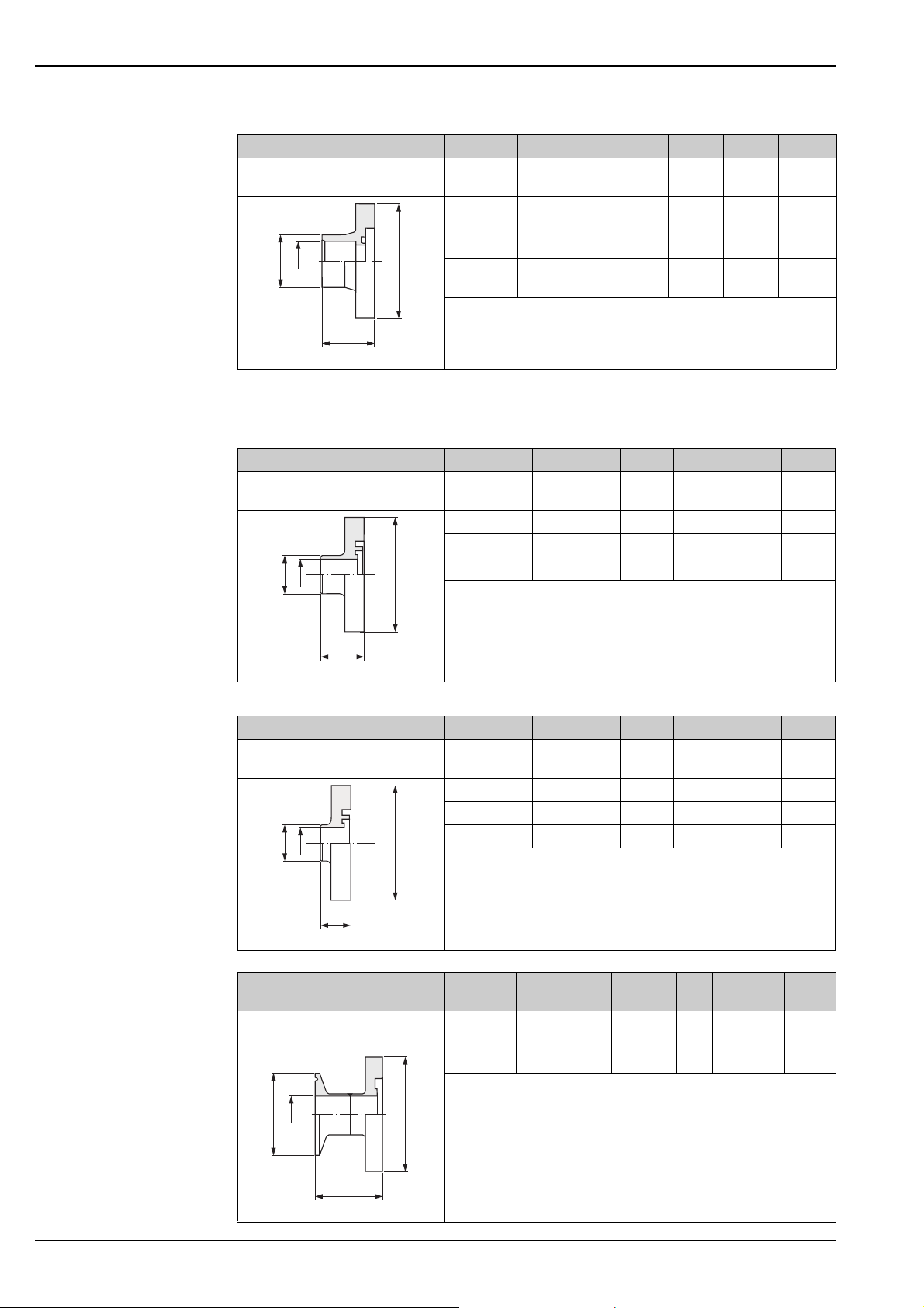
Proline Promag 50H, 53H
Adhesive fitting Sensor Fits to di G L H × B
PVC
5*H**-R/S***********
di
G
HxB
L
A0005566
Process connections with aseptic gasket seal (DN 2 to 25 / 1/12 to 1")
Weld socket for DIN Sensor Fits to di G L H × B
1.4404 / 316L
5*H**-U***********
G
di
HxB
DN
[mm]
Pipe
[mm] [inch] [mm] [mm] [mm] [mm]
2 to 8 ½" [inch] 21.5 27.3 38.5 62 × 42
2 to 8 20 × 2 [mm]
20.2 27.0 38.5 62 × 42
(DIN 8062)
15 20 × 2 [mm]
20.2 27.0 28.0 62 × 42
(DIN 8062)
• Fitting length = (2 × L) + 86 mm
• The requisite ground rings can be ordered as accessories
(Order No. DK5HR-****).
DN
[mm]
Piping
DIN 11850 [mm] [mm] [mm] [mm]
2 to 8 14 × 2 9 14 23.3 62 × 42
15 20 × 2 16 20 23.3 62 × 42
25 (DIN) 30 × 2 26 30 23.3 72 × 55
• Fitting length = (2 × L) + 86 mm
• If pigs are used for cleaning, it is essential to take the inside diameters of
measuring tube and process connection (di) into account!
L
A0003870
Weld socket for ODT/SMS Sensor Fits to di G L H × B
1.4404 / 316L
5*H**-V***********
DN
[mm]
Piping
ODT/SMS [mm] [mm] [mm] [mm]
2 to 8 12.7 × 1.65 9.0 12.7 16.1 62 × 42
15 19.1 × 1.65 16.0 19.1 16.1 62 × 42
G
di
HxB
25 (1" ANSI) 24.5 × 1.65 22.6 25.4 16.1 72 × 55
• Fitting length = (2 × L) + 86 mm
• If pigs are used for cleaning, it is essential to take the inside diameters of
measuring tube and process connection (di) into account!
L
A0003871
Clamp ISO 2852, Fig. 2 Sensor Fits to
piping
1.4404 / 316L
5*H**-W***********
DN
[mm]
ISO 2037 /
BS 4825-1
Clamp
di G L H × B
ISO 2850
Diameter
[mm] [mm] [mm] [mm] [mm]
25 (1" ANSI) Tube 24.5 × 1.65 25 22.6 50.5 44.3 72 × 55
• Fitting length = (2 × L) + 86 mm
• If pigs are used for cleaning, it is essential to take the inside diameters of
G
di
HxB
measuring tube and process connection (di) into account!
L
A0005560
32 Endress+Hauser
Page 33
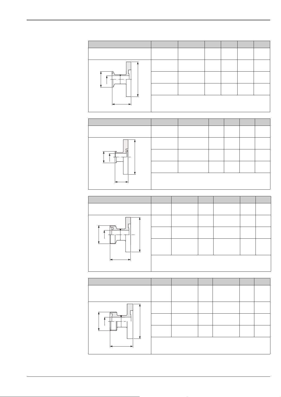
Proline Promag 50H, 53H
Clamp DIN 32676 Sensor Fits to di G L H × B
1.4404 / 316L
5*H**-0***********
DN
[mm]
Piping
DIN 11850 [mm] [mm] [mm] [mm]
2 to 8 Tube 14 × 2
10 34.0 41.0 62 × 42
(DN 10)
15 Tube 20 × 2
G
di
HxB
(DN 15)
25 (DIN) Tube 30 × 2
16 34.0 41.0 62 × 42
26 50.5 44.5 72 × 55
(DN 25)
• Fitting length = (2 × L) + 86 mm
L
• If pigs are used for cleaning, it is essential to take the inside diameters of
A0005556
measuring tube and process connection (di) into account!
Tri-Clamp for L14 AM7 Sensor Fits to di G L H × B
1.4404 / 316L
5*H**-1***********
DN
[mm]
Piping
OD [mm] [mm] [mm] [mm]
2 to 8 Tube 12.7 × 1.65
9.4 25.0 28.5 62 × 42
(OD ½")
15 Tube 19.1 × 1.65
G
di
HxB
(ODT ¾")
25 (1" ANSI) Tube 25.5 × 1.65
15.8 25.0 28.5 62 × 42
22.1 50.4 28.5 72 × 55
(ODT 1")
• Fitting length = (2 × L) + 86 mm
L
• If pigs are used for cleaning, it is essential to take the inside diameters of
A0003872
measuring tube and process connection (di) into account!
Coupling SC DIN 11851 Sensor Fits to di G L H × B
Threaded adapter; 1.4404 / 316L
5*H**-2***********
DN
[mm]
Piping
DIN 11850 [mm] [mm] [mm] [mm]
2 to 8 Tube 12 × 1
10 Rd 28 × 1/8" 44 62 × 42
(DN 10)
15 Tube 18 × 1.5
G
di
HxB
(DN 15)
25 (DIN) Tube 28 × 1
16 Rd 34 × 1/8" 44 62 × 42
26 Rd 52 × 1/6" 52 72 × 55
or 28 × 1.5
(DN 25)
L
• Fitting length = (2 × L) + 86 mm
• If pigs are used for cleaning, it is essential to take the inside diameters of
A0005553
measuring tube and process connection (di) into account!
Coupling DIN 11864-1 Sensor Fits to di G L H × B
Aseptic threaded adapter, Form A
1.4404 / 316L
5*H**-3***********
DN
[mm]
Piping
DIN 11850 [mm] [mm] [mm] [mm]
2 to 8 Tube 13 × 1.5
10 Rd 28 × 1/8" 42 62 × 42
(DN 10)
G
di
HxB
(DN 15)
25 (DIN) Tube 29 × 1.5
15 Tube 19 × 1.5
16 Rd 34 × 1/8" 42 62 × 42
26 Rd 52 × 1/6" 49 72 × 55
(DN 25)
• Fitting length = (2 × L) + 86 mm
L
• If pigs are used for cleaning, it is essential to take the inside diameters of
A0005558
measuring tube and process connection (di) into account!
Endress+Hauser 33
Page 34
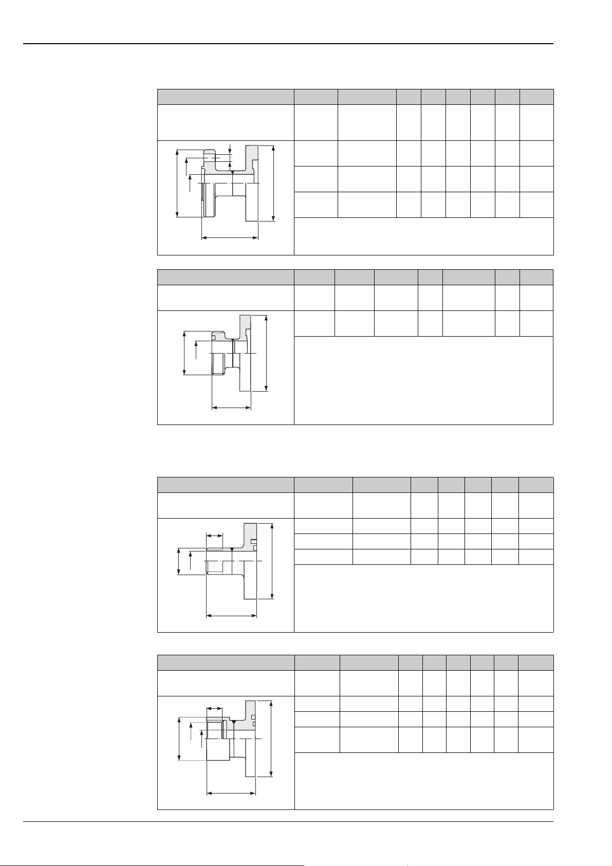
Proline Promag 50H, 53H
Flange DIN 11864-2 Sensor Fits to di G L LK M H × B
Aseptic grooved flange, Form A
1.4404 / 316L
5*H**-4***********
M
LK
G
di
HxB
L
A0005559
Coupling SMS 1145 Sensor Fits to SMS 1145 di G L H × B
Threaded adapter; 1.4404 / 316L
5*H**-5***********
di
G
HxB
DN
[mm]
2 to 8 Tube 13 × 1.5
Piping
DIN 11850 [mm] [mm] [mm] [mm] [mm] [mm]
10 54 48.5 37 9 62 × 42
(DN 10)
15 Tube 19 × 1.5
16 59 48.5 42 9 62 × 42
(DN 15)
25 (DIN) Tube 29 × 1.5
26 70 48.5 53 9 72 × 55
(DN 25)
• Fitting length = (2 × L) + 86 mm
•If pigs are used for cleaning, it is essential to take the inside diameters of
measuring tube and process connection (di) into account!
DN
[mm]
25
PipingODDiameter
[mm] [mm] [mm] [mm] [mm]
1" 25 22.6 Rd 40 × 1/6" 30.8 72 × 55
(1" ANSI)
• Fitting length = (2 × L) + 86 mm
• If pigs are used for cleaning, it is essential to take the inside diameters of
measuring tube and process connection (di) into account!
L
A0005564
Process connections orderable only as accessories with O-ring seal (DN 2 to 25 / 1/12 to 1")
Exernal pipe thread Sensor Fits to di G L S H × B
1.4404 / 316L
DKH**-GD**
S
G
di
HxB
L
A0005563
Internal pipe thread Sensor Fits to di G D L S H × B
1.4404 / 316L
DKH**-GC**
S
G
D
di
HxB
DN
[mm]
NP
internal thread [mm] [inch] [mm] [mm] [mm]
2 to 8 NPT 3/8" 10 3/8" 50 15.5 62 × 42
15 NPT ½" 16 ½" 50 20.0 62 × 42
25 (1" ANSI) NPT 1" 25 1" 55 25.0 72 × 55
• Fitting length = (2 × L) + 86 mm
DN
[mm]NPexternal thread [mm] [inch] [mm] [mm] [mm] [mm]
2 to 8 NPT 3/8" 8.9 3/8" 22 45 13 62 × 42
15 NPT ½" 16.0 ½" 27 45 14 62 × 42
25
NPT 1" 27.2 1" 40 51 17 72 × 55
(1" ANSI)
• Fitting length = (2 × L) + 86 mm
L
A0005565
34 Endress+Hauser
Page 35
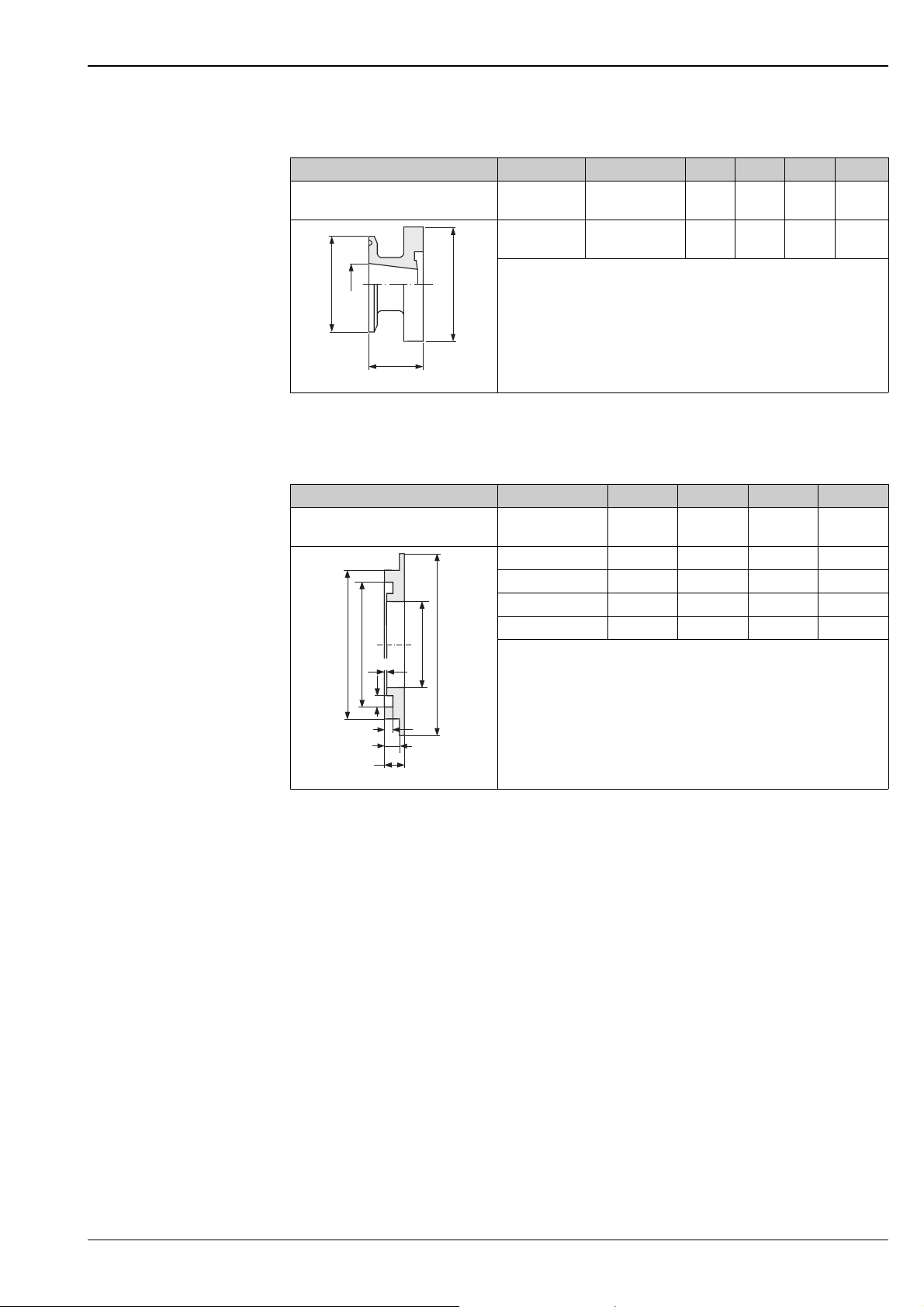
Proline Promag 50H, 53H
Process connections orderable only as accessories with aseptic gasket seal (DN 15)
Tri-Clamp L14 AM17 Sensor Fits to di G L H × B
1.4404 / 316L
DKH**-HF**
DN
[mm]
Piping
OD [mm] [mm] [mm] [mm]
15 Tube 25.4 × 1.65
22.1 50.4 28.5 62 × 42
(ODT 1")
• Fitting length = (2 × L) + 86 mm
G
di
HxB
• If pigs are used for cleaning, it is essential to take the inside diameters of
measuring tube and process connection (di) into account!
L
A0005555
Ground rings (accessories for PVDF flanges / PVC adhesive fitting) (DN 2 to 25 / 1/12 to 1")
Ground ring Sensor di B C D
1.4435/316L, Alloy C-22, Tantalum
DK5HR – ****
ØC
ØC
ØB
ØB
0.5
0.5
ØD
ØD
Ødi
Ødi
DN
[mm] [mm] [mm] [mm] [mm]
2 to 8 9.0 22.0 17.6 33.9
15 16.0 29.0 24.6 33.9
25 (1" ANSI) 22.6 36.5 31.2 43.9
25 (DIN) 26.0 39.0 34.6 43.9
1.9
1.9
3.4
3.4
3.5
3.5
A0005568
Endress+Hauser 35
Page 36
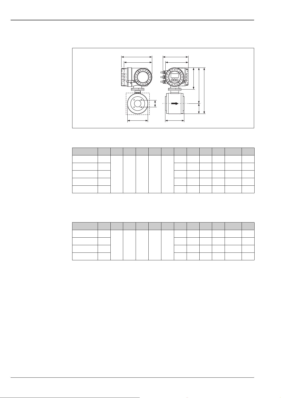
Compact version, aluminum field housing DN 40 to 100 (1½ to 4")
Esc
E
-
+
Proline Promag 50H, 53H
A
B
C
D
E
G
H
X2
di
F
K
L
Dimensions in SI units
DN L A B C D E F G H K X2 di
40 140
50 140 77 267 344 153 M8 × 4 48.1
65 140 77 267 344 153 M8 × 6 59.9
227 207 187 168 160
80 200 102 292 394 203 M12 × 4 72.6
100 200 102 292 394 203 M12 × 6 97.5
Total length depends on the process connections.
All dimensions in [mm]
64 255 319 128 M8 × 4 35.3
A0005425
Dimensions in US units
DN L A B C D E F G H K X2 di
1½" 5.51
2" 5.51 3.03 10.5 13.5 6.02 M8 × 4 1.89
8.94 8.15 7.36 6.61 6.30
3" 7.87 4.02 11.5 15.5 7.99 M12 × 4 2.86
4" 7.87 4.02 11.5 15.5 7.99 M12 × 6 3.84
Total length depends on the process connections.
All dimensions in [inch]
2.52 10.0 12.6 5.04 M8 × 4 1.39
36 Endress+Hauser
Page 37
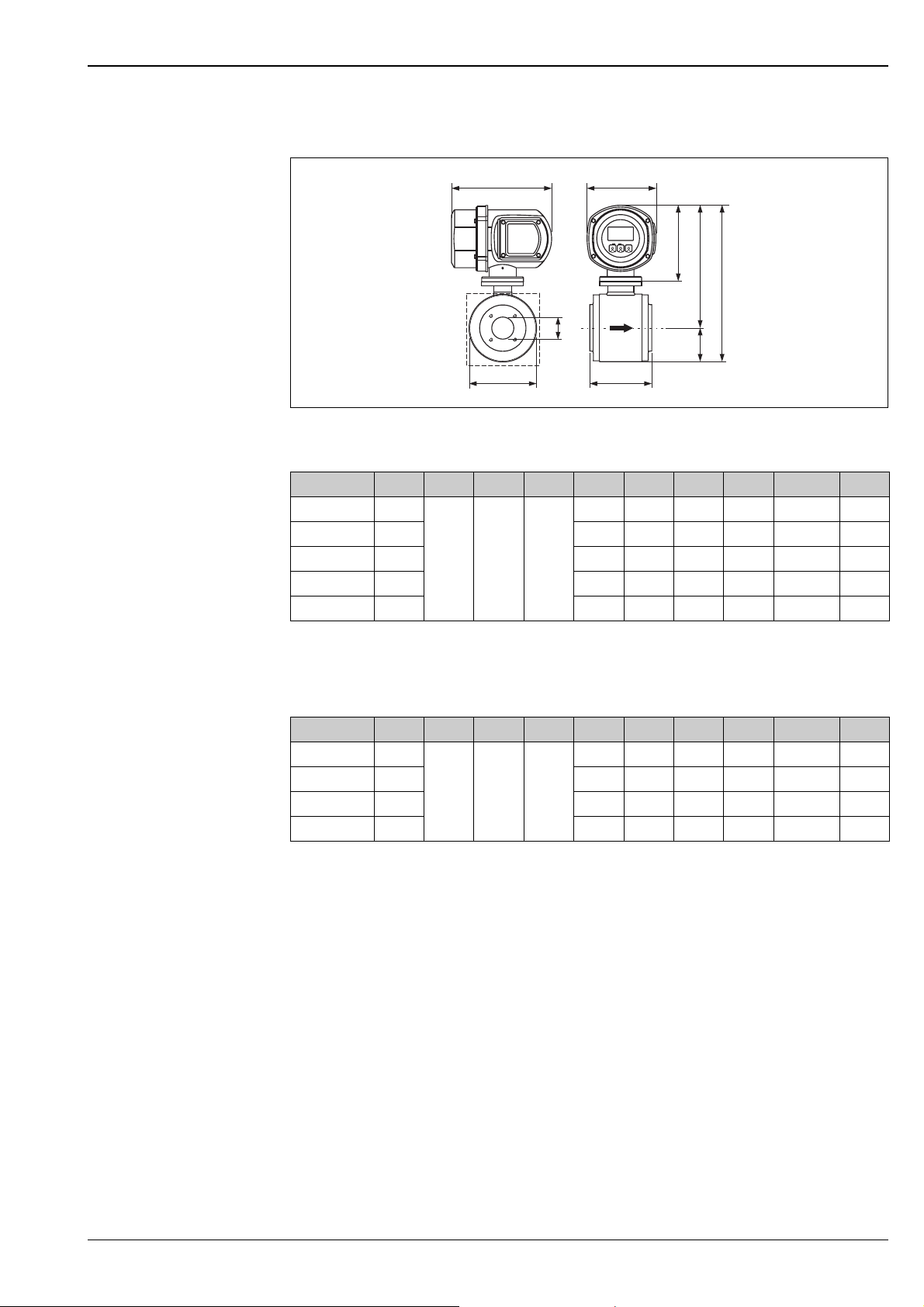
Proline Promag 50H, 53H
Esc
E
-
+
Compact version, stainless-steel field housing DN 40 to 100 (1½ to 4")
A
B
C
E
F
X2
di
D
K
L
Dimensions in SI units
DN L A B C D E F K X2 di
40 140
50 140 77 278 355 153 M8 × 4 48.1
65 140 77 278 355 153 M8 × 6 59.9
220 153 171
80 200 102 303 405 203 M12 × 4 72.6
100 200 102 303 405 203 M12 × 6 97.5
Total length depends on the process connections.
All dimensions in [mm]
64 266 330 128 M8 × 4 35.3
A0005428
Dimensions in US units
DN L A B C D E F K X2 di
1½" 5.51
2" 5.51 3.03 10.9 14.0 6.02 M8 × 4 1.89
3" 7.87 4.02 11.9 15.9 7.99 M12 × 4 2.86
8.66 6.02 6.73
4" 7.87 4.02 11.9 15.9 7.99 M12 × 6 3.84
Total length depends on the process connections.
All dimensions in [inch]
2.52 10.5 13.0 5.04 M8 × 4 1.39
Endress+Hauser 37
Page 38
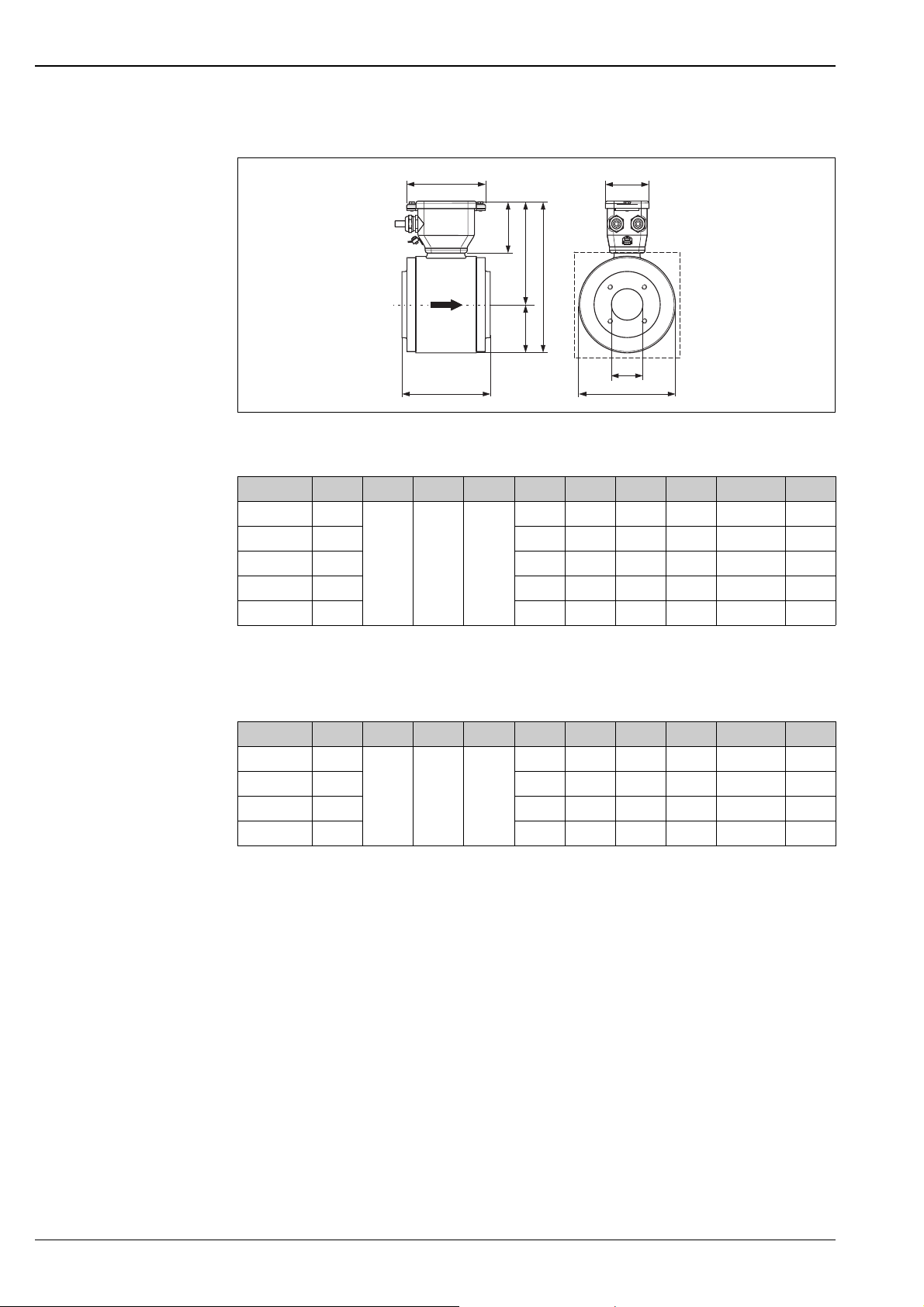
Sensor, remote version DN 40 to 100 (1½ to 4")
Proline Promag 50H, 53H
A
C
E
D
L
X2
F
B
di
K
Dimensions in SI units
DN L A B C D E F K X2 di
40 140
50 140 77.0 164.0 241 154 M8 × 4 48.1
65 140 77.0 164.0 241 154 M8 × 6 59.9
80 200 101.5 188.5 290 203 M12 × 4 72.6
100 200 101.5 188.5 290 203 M12 × 6 97.5
Total length depends on the process connections.
All dimensions in [mm]
125 70 75
64.5 151.5 216 129 M8 × 4 35.3
A0005535
Dimensions in US units
DN L A B C D E F K X2 di
1½" 5.51
2" 5.51 3.03 6.46 9.49 6.06 M8 × 4 1.89
3" 7.87 4.00 7.42 11.4 7.99 M12 × 4 2.86
4" 7.87 4.00 7.42 11.4 7.99 M12 × 6 3.84
Total length depends on the process connections.
All dimensions in [inch]
4.92 2.76 2.95
2.54 5.96 8.50 5.08 M8 × 4 1.39
38 Endress+Hauser
Page 39
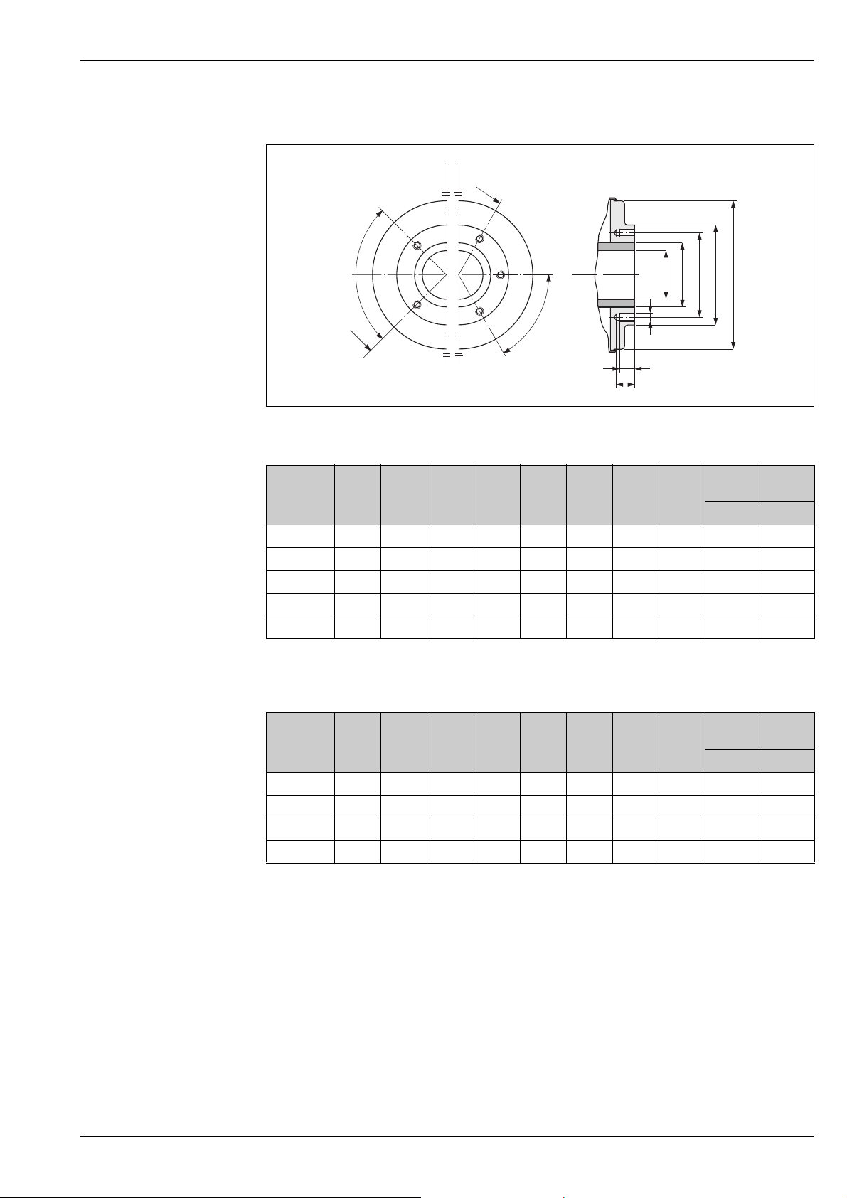
Proline Promag 50H, 53H
Sensor, front view (without process connections) DN 40 to 100 (1½ to 4")
Z–Z
Z
K
E
D
B
A
C
L
Z
F
G
H
Dimensions in SI units
DN A B C D E F G H K
90°
Threaded holes
40 122 86 71.0 51.0 35.3 M 8 15 18 4 –
50 147 99 83.5 63.5 48.1 M 8 15 18 4 –
65 147 115 100.0 76.1 59.9 M 8 15 18 – 6
80 197 141 121.0 88.9 72.6 M 12 15 20 4 –
100 197 162 141.5 114.3 97.5 M 12 15 20 – 6
All dimensions in [mm]
Dimensions in US units
DN A B C D E F G H K
90°
Threaded holes
1½" 4.80 3.39 2.80 2.01 1.39 M 8 0.59 0.71 4 –
2" 5.79 3.90 3.29 2.50 1.89 M 8 0.59 0.71 4 –
3" 7.76 5.55 4.76 3.50 2.86 M 12 0.59 0.79 4 –
4" 7.76 6.38 5.57 4.50 3.84 M 12 0.59 0.79 – 6
All dimensions in [inch]
±0.5°
±0.5°
60°
60°
L
L
±0.5°
±0.5°
A0005528
Endress+Hauser 39
Page 40
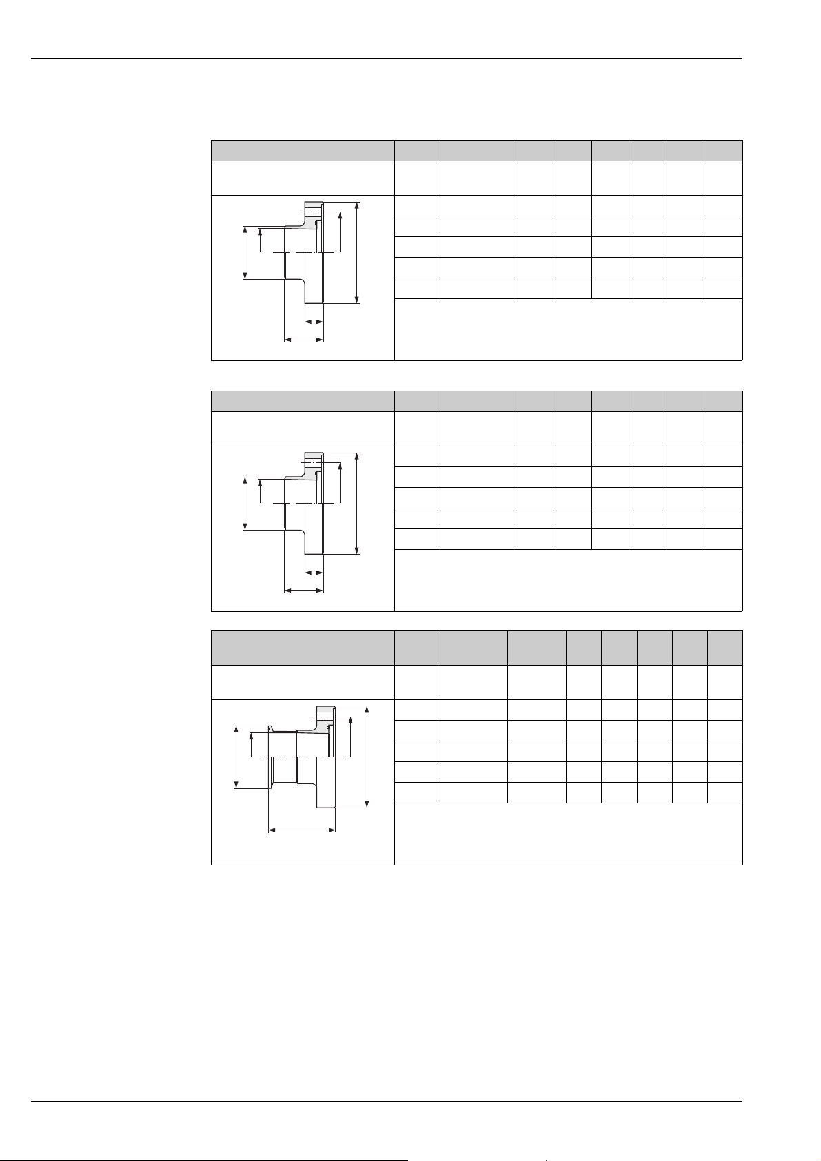
Proline Promag 50H, 53H
Process connections with aseptic gasket seal DN 40 to 100 (1½ to 4")
Weld socket for DIN Sensor Fits to di G D L L1 LK
1.4404 / 316L
5*H**-U***********
di
G
LK
D
L1
L
Weld socket for ODT/SMS Sensor Fits to di G D L L1 LK
1.4404 / 316L
5*H**-V***********
di
G
LK
D
L1
L
DN
[mm]
Piping
DIN 11850 [mm] [mm] [mm] [mm] [mm] [mm]
40 42 × 2 38.0 43 92 42 19 71.0
50 54 × 2 50.0 55 105 42 19 83.5
65 70 × 2 66.0 72 121 42 21 100.0
80 85 × 2 81.0 87 147 42 24 121.0
100 104 × 2 100.0 106 168 42 24 141.5
• – Fitting length for DN 40 to 65 = (2 × L) + 136 mm
– Fitting length for DN 80 to 100 = (2 × L) + 196 mm
• If pigs are used for cleaning, it is essential to take the inside diameters of
A0005541
measuring tube and process connection (di) into account!
DN
[mm]
Piping
OD/SMS [mm] [mm] [mm] [mm] [mm] [mm]
40 38.1 × 1.65 35.3 40 92 42 19 71.0
50 50.8 × 1.65 48.1 55 105 42 19 83.5
65 63.5 × 1.65 59.9 66 121 42 21 100.0
80 76.2 × 1.65 72.6 79 147 42 24 121.0
100 101.6 × 1.65 97.5 104 168 42 24 141.5
• – Fitting length for DN 40 to 65 = (2 × L) + 136 mm
– Fitting length for DN 80 to 100 = (2 × L) + 196 mm
• If pigs are used for cleaning, it is essential to take the inside diameters of
A0005541
measuring tube and process connection (di) into account!
Clamp ISO 2852, Fig. 2 Sensor Fits to
piping
1.4404 / 316L
5*H**-W***********
DN
[mm]
ISO 2037 /
BS 4825-1
40 38.0 × 1.6 38.0 35.6 50.5 92 68.5 71.0
50 51.0 × 1.6 51.0 48.6 64.0 105 68.5 83.5
di
G
LK
D
65 63.5 × 1.6 63.5 60.3 77.5 121 68.5 100.0
80 76.1 × 1.6 76.1 72.9 91.0 147 68.5 121.0
100 101.6 × 2.0 101.6 97.6 119.0 168 68.5 141.5
• – Fitting length for DN 40 to 65 = (2 × L) + 136 mm
L
A0005544
– Fitting length for DN 80 to 100 = (2 × L) + 196 mm
• If pigs are used for cleaning, it is essential to take the inside diameters of
measuring tube and process connection (di) into account!
Clamp
di G D L LK
ISO 2852
Diameter
[mm] [mm] [mm] [mm] [mm] [mm]
40 Endress+Hauser
Page 41
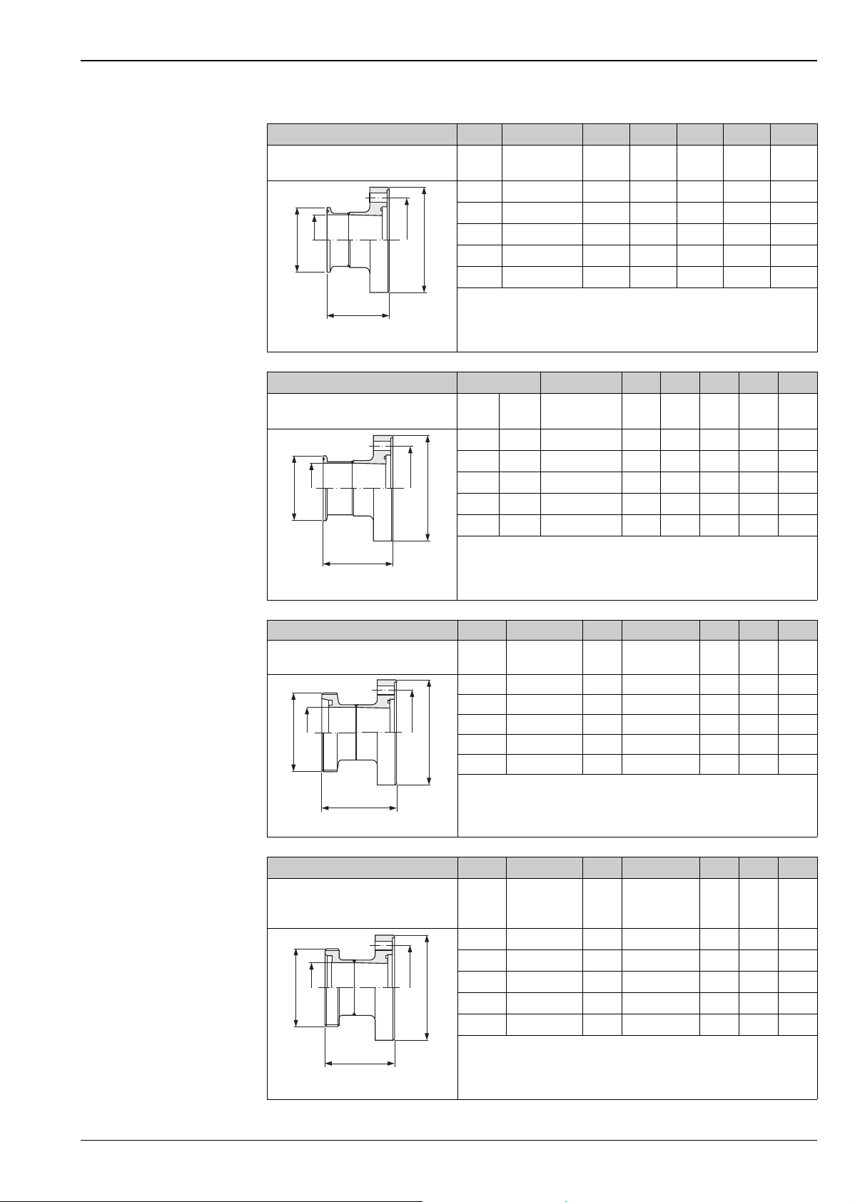
Proline Promag 50H, 53H
Clamp DIN 32676 Sensor Fits to di G D L LK
1.4404 / 316L
5*H**-0***********
DN
[mm]
Piping
DIN 11850 [mm] [mm] [mm] [mm] [mm]
40 42 × 2 38 50.5 92 61.5 71.0
50 54 × 2 50 64.0 105 61.5 83.5
di
G
LK
D
65 70 × 2 66 91.0 121 68.0 100.0
80 85 × 2 81 106.0 147 68.0 121.0
100 104 × 2 100 119.0 168 68.0 141.5
• – Fitting length for DN 40 to 65 = (2 × L) + 136 mm
L
A0005539
– Fitting length for DN 80 to 100 = (2 × L) + 196 mm
• If pigs are used for cleaning, it is essential to take the inside diameters of
measuring tube and process connection (di) into account!
Tri-Clamp L14 AM7 Sensor Fits to di G D L LK
1.4404 / 316L
5*H**-1***********
DN
[mm]DN[inch]
Piping
OD [mm] [mm] [mm] [mm] [mm]
40 1½" 38.1 × 1.65 34.8 50.4 92 68.8 71.0
50 2" 50.8 × 1.65 47.5 63.9 105 68.8 83.5
di
G
LK
D
65 – 63.5 × 1.65 60.2 77.4 121 68.8 100.0
80 3" 76.2 × 1.65 72.9 90.9 147 68.8 121.0
100 4" 101.6 × 1.65 97.4 118.9 168 68.8 141.5
• – Fitting length for DN 40 to 65 = (2 × L) + 136 mm
L
A0005543
– Fitting length for DN 80 to 100 = (2 × L) + 196 mm
• If pigs are used for cleaning, it is essential to take the inside diameters of
measuring tube and process connection (di) into account!
Coupling SC DIN 11851 Sensor Fits to di G D L LK
1.4404 / 316L
5*H**-2***********
DN
[mm]
Piping
DN 11850 [mm] [mm] [mm] [mm] [mm]
40 42 × 2 38 Rd 65 × 1/6" 92 72 71.0
50 54 × 2 50 Rd 78 × 1/6" 105 74 83.5
di
G
LK
D
65 70 × 2 66 Rd 95 × 1/6" 121 78 100.0
80 85 × 2 81 Rd 110 × 1/6" 147 83 121.0
100 104 × 2 100 Rd 130 × 1/6" 168 92 141.5
• – Fitting length for DN 40 to 65 = (2 × L) + 136 mm
L
A0005540
– Fitting length for DN 80 to 100 = (2 × L) + 196 mm
• If pigs are used for cleaning, it is essential to take the inside diameters of
measuring tube and process connection (di) into account!
Coupling DIN 11864-1 Sensor Fits to di G D L LK
Aseptic threaded adapter, Form A
1.4404 / 316L
DN
[mm]
Piping
DN 11850 [mm] [mm] [mm] [mm] [mm]
5*H**-3***********
40 42 × 2 38 Rd 65 × 1/6" 92 71 71.0
50 54 × 2 50 Rd 78 × 1/6" 105 71 83.5
di
G
LK
D
65 70 × 2 66 Rd 95 × 1/6" 121 76 100.0
80 85 × 2 81 Rd 110 × 1/6" 147 82 121.0
100 104 × 2 100 Rd 130 × 1/6" 168 90 141.5
• – Fitting length for DN 40 to 65 = (2 × L) + 136 mm
L
A0005545
– Fitting length for DN 80 to 100 = (2 × L) + 196 mm
• If pigs are used for cleaning, it is essential to take the inside diameters of
measuring tube and process connection (di) into account!
Endress+Hauser 41
Page 42
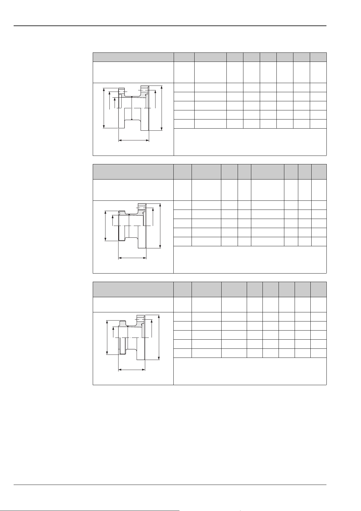
Proline Promag 50H, 53H
Flange DIN 11864-2 Sensor Fits to di G D L LK 1 LK 2
Aseptic flat flange, Form A
1.4404 / 316L
5*H**-4***********
LK 2
di
G
L
LK 1
D
A0005546
DN
[mm]
Piping
DN 11850 [mm] [mm] [mm] [mm] [mm] [mm]
40 42 × 2 3882926471.065
50 54 × 2 50 94 105 64 83.5 77
65 70 × 2 66 113 121 64 100.0 95
80 85 × 2 81 133 147 98 121.0 112
100 104 × 2 100 159 168 98 141.5 137
• – Fitting length for DN 40 to 65 = (2 × L) + 136 mm
– Fitting length for DN 80 to 100 = (2 × L) + 196 mm
• If pigs are used for cleaning, it is essential to take the inside diameters of
measuring tube and process connection (di) into account!
Coupling SMS 1145 Sensor Fits to
Threaded adapter; 1.4404 / 316L
5*H**-5***********
DN
[mm]
Piping
OD
40 38.1 × 1.65 38.0 35.5 Rd 60 × 1/6" 92 63 71.0
50 50.8 × 1.65 51.0 48.5 Rd 70 × 1/6" 105 65 83.5
di
G
LK
D
65 63.5 × 1.65 63.5 60.5 Rd 85 × 1/6" 121 70 100.0
80 76.2 × 1.65 76.0 72.0 Rd 98 × 1/6" 147 75 121.0
100 101.6 × 1.65 101.6 97.6 Rd 132 × 1/6" 168 70 141.5
• – Fitting length for DN 40 to 65 = (2 × L) + 136 mm
L
A0005538
Coupling ISO 2853 Sensor
Threaded adapter; 1.4404 / 316L
5*H**-6***********
– Fitting length for DN 80 to 100 = (2 × L) + 196 mm
• If pigs are used for cleaning, it is essential to take the inside diameters of
measuring tube and process connection (di) into account!
Fits to
piping
DN
ISO 2037 /
[mm]
BS 4825-1
40 38.0 × 1.6 38.0 35.6 50.6 92 61.5 71.0
50 51.0 × 1.6 51.0 48.6 64.1 105 61.5 83.5
di
G
LK
D
65 63.5 × 1.6 63.5 60.3 77.6 121 61.5 100.0
80 76.1 × 1.6 76.1 72.9 91.1 147 61.5 121.0
100 101.6 × 2.0 101.6 97.6 118.1 168 61.5 141.5
• – Fitting length for DN 40 to 65 = (2 × L) + 136 mm
L
A0005542
– Fitting length for DN 80 to 100 = (2 × L) + 196 mm
• If pigs are used for cleaning, it is essential to take the inside diameters of
measuring tube and process connection (di) into account!
SMS
1145
di G D L LK
Dia-
meter
[mm] [mm] [mm] [mm] [mm]
[mm]
ISO 2853 di G D L LK
Diameter
[mm] [mm] [mm] [mm] [mm] [mm]
42 Endress+Hauser
Page 43
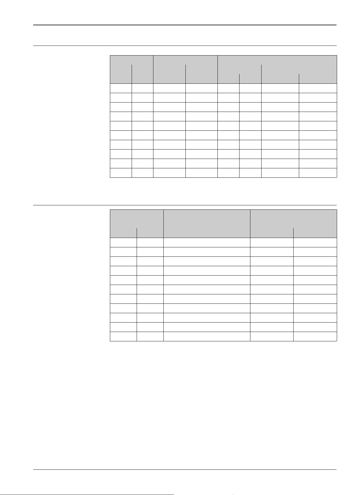
Proline Promag 50H, 53H
Weight
Nominal diameter Compact version (DIN) Remote version (without cable; DIN)
Sensor Transmitter (wall-mount housing)
[mm] [inch] [kg] [lbs] [kg] [lbs] [kg] [lbs]
2 1/12" 5.2 11.5 2.0 4 6 13
4 1/8" 5.2 11.5 2.0 4 6 13
8 3/8" 5.3 11.7 2.0 4 6 13
15 ½" 5.4 11.9 1.9 4 6 13
25 1" 5.5 12.1 2.8 6 6 13
40 1½" 6.5 14.3 4.5 10 6 13
50 2" 9.0 19.8 7.0 15 6 13
65 – 9.5 20.9 7.5 17 6 13
80 3" 19.0 41.9 17.0 37 6 13
100 4" 18.5 40.8 16.5 36 6 13
• Transmitter (compact version): 3.4 kg (7.5 lbs)
• Weight data valid for standard pressure ratings and without packaging material.
Measuring tube specifications
Nominal diameter Pressure rating
1)
Internal diameter
EN (DIN) PFA
[mm] [inch] [bar] [mm] [inch]
2 1/12" PN 16 / PN 40 2.25 0.09
4 1/8" PN 16 / PN 40 4.5 0.18
8 3/8" PN 16 / PN 40 9.0 0.35
15 ½" PN 16 / PN 40 16.0 0.63
– 1" PN 16 / PN 40 22.6 0.89
25 – PN 16 / PN 40 26.0 1.02
40 1½" PN 16 35.3 1.39
50 2" PN 16 48.1 1.89
65 – PN 16 59.9 2.36
80 3" PN 16 72.6 2.86
100 4" PN 16 97.5 3.84
1)
Pressure rating depends on the process connection and the seals used.
2)
Internal diameter of process connections.
2)
Endress+Hauser 43
Page 44
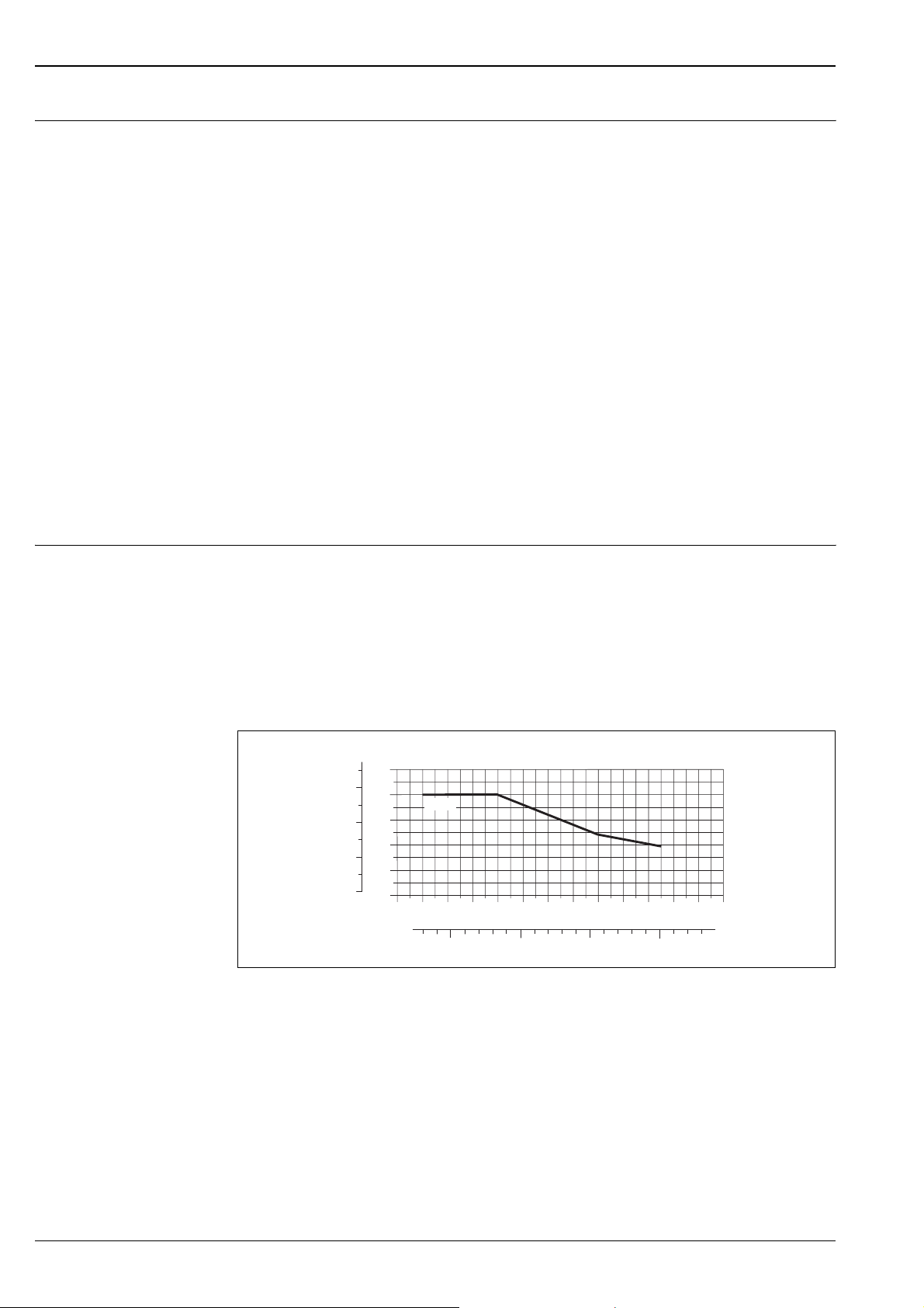
Material • Transmitter housing:
– Compact housing: powder coated die-cast aluminium or stainless-steel field housing (1.4301/304)
– Wall-mounted housing: powder coated die-cast aluminium
• Sensor housing: stainless steel 1.4301/304
• Wall mounting kit (holder panel): 1.4301/304
• Measuring tube: stainless steel 1.4301/304
• Lining material: PFA (USP Class VI; FDA 21 CFR 177.1550; 3A)
• Flanges:
– All connections 1.4404/316L
– Flanges (EN (DIN), ANSI, JIS) made of PVDF
– Adhesive fitting made of PVC
• Ground rings: 1.4435/316L (optional: Alloy C-22, Tantalum)
• Electrodes:
– Standard: 1.4435/316L
– Optional: Alloy C-22, Tantalum, Platinum (up to DN 25 / 1" only)
• Seals:
– DN 2 to 25 (1/12 to 1"): O-Ring (EPDM, Viton, Kalrez), moulded seal (EPDM*, Viton, Silicone*)
– DN 40 to 100 (1½ to 4"): moulded seal (EPDM*, Silicone*)
* = USP Class VI; FDA 21 CFR 177.2600; 3A
Proline Promag 50H, 53H
Material load diagram
Caution!
"
The following diagrams contain material load diagrams (reference curves) for flange materials with regard to
the medium temperature.
Weld socket to DIN EN ISO 1127, ODT/SMS;
coupling to ISO 228 / DIN 2999 / NPT
Material: 1.4404 / 316L (with O-ring)
[bar][psi]
45
650
600
500
400
300
40
35
30
25
20
-60
PN40
-20
-40
020
0-40 100 200 300
40 60 80 100 120 140 160 180 [°C]
360 [°F]
A0005586
44 Endress+Hauser
Page 45
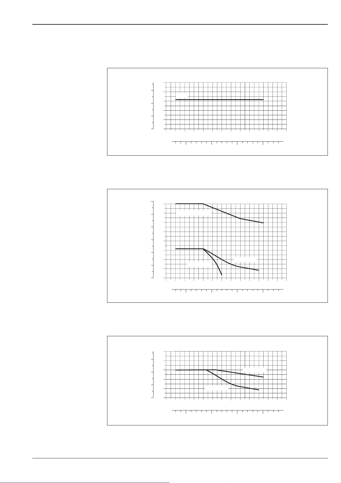
Proline Promag 50H, 53H
Weld socket to DIN 11850, ODT/SMS; Clamp (ISO 2852, DIN 32676, L14 AM7);
coupling (DIN 11851, DIN 11864-1, ISO 2853, SMS 1145), flange DIN 11864-2
Material: 1.4404 / 316L (with moulded seal)
[bar]
[psi]
25
300
200
100
20
15
10
5
0
0
-60
-40
PN16
-20
40 60 80 100 120 140 160 180 [°C]
020
0-40 100 200 300
Flange connection to EN 1092-1 (DIN 2501), adhesive fitting
Material: 1.4404 / 316L, PVDF, PVC-U
[bar][psi]
600
40
-60
-40
PN40 (1.4404/316L)
PN16 (PVC-U)
-20
020
40 60 80 100 120 140 160 180 [°C]
PN16 (PVDF)
0-40 100 200 300
500
400
300
200
100
35
30
25
20
15
10
5
0
0
360 [°F]
A0005596
360 [°F]
A0005597
Flange connection to ANSI B16.5
Material: 1.4404 / 316L, PVDF
[bar][psi]
25
300
20
200
15
Cl150 (316L)
10
100
5
0
0
-40
-20
-60
0-40 100 200 300
Cl150 (PVDF)
40 60 80 100 120 140 160 180 [°C]
020
360 [°F]
A0005598
Endress+Hauser 45
Page 46
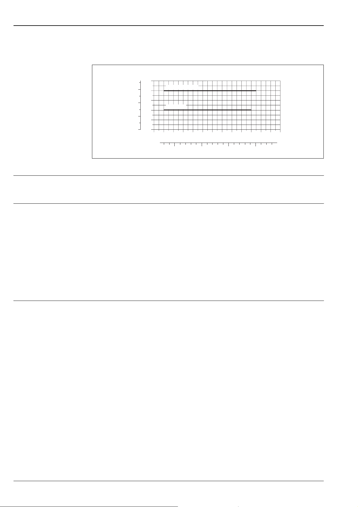
Flange connection to JIS B2220
Material: 1.4404 / 316L, PVDF
[bar][psi]
25
300
20
15
200
10
100
5
0
0
-60
-40
20K (1.4404/316L)
10K (PVDF)
-20
020
Proline Promag 50H, 53H
40 60 80 100 120 140 160 180 [°C]
0-40 100 200 300
Fitted electrodes Measuring electrodes and empty pipe detection electrodes
• Standard with: 1.4435/316L, Alloy C-22, Tantalum, Platinum
• DN 2 to 15 (1/12 to ½"): without empty pipe detection electrode
Process connections With O-ring:
• Weld sockets (DIN EN ISO 1127, ODT/SMS)
• Flange (EN (DIN), ANSI, JIS)
• PVDF flange (EN (DIN), ANSI, JIS)
• External pipe thread
• Internal pipe thread
• Hose connection
• PVC adhesive fittings
With gasket seals:
• Weld sockets DIN 11850, ODT/SMS
• Clamps (ISO 2852, DIN 32676, L14 AM7)
• Threaded joint DIN 11851, DIN 11864-1, ISO 2853, SMS 1145
• Flange DIN 11864-2
Surface roughness (All data refer to parts in contact with medium)
• Measuring tube lining with PFA: ≤ 0.4 μm (15 μin)
• Electrodes
– 1.4435/316L, Alloy C-22, Tantalum, Platinum: ≤ 0.3 to 0.5 μm (12 to 20 μin)
• Process connection made of stainless-steel: ≤ 0.8 μm (31 μin)
360 [°F]
A0005599
46 Endress+Hauser
Page 47

Proline Promag 50H, 53H
Human interface
Display elements • Liquid crystal display: backlit, two lines (Promag 50) or four lines (Promag 53) with 16 characters per line
• Custom configurations for presenting different measured-value and status variables
• Totalizer
– Promag 50: 2 totalizers
– Promag 53: 3 totalizers
Operating elements Unified operation concept for both types of transmitter:
Promag 50:
• Local operation via three keys (S, O, F)
• Quick Setup menus for straightforward commissioning
Promag 53:
• Local operation via three keys (S, O, F)
• Application-specific Quick Setup menus for straightforward commissioning
Language groups Language groups available for operation in different countries:
Promag 50, Promag 53:
• Western Europe and America (WEA):
English, German, Spanish, Italian, French, Dutch, Portuguese
• Eastern Europe and Scandinavia (EES):
English, Russian, Polish, Norwegian, Finnish, Swedish, Czech
• South and east Asia (SEA):
English, Japanese, Indonesian
Promag 53:
• China (CN):
English, Chinese
You can change the language group via the operating program "FieldCare".
Remote operation • Promag 50: Remote control via HART, PROFIBUS DP/PA
• Promag 53: Remote control via HART, PROFIBUS DP/PA, MODBUS RS485, FOUNDATION Fieldbus
Certificates and approvals
CE mark The measuring system is in conformity with the statutory requirements of the EC Directives.
Endress+Hauser confirms successful testing of the device by affixing to it the CE mark.
C-tick mark The measuring system meets the EMC requirements of the "Australian Communications and Media Authority
(ACMA)".
Pressure measuring device approval
The measuring devices can be ordered with or without PED (Pressure Equipment Directive). If a device with
PED is required, this must be ordered explicitly. For devices with nominal diameters less than or equal to
DN 25 (1"), this is neither possible nor necessary.
• With the identification PED/G1/III on the sensor nameplate, Endress+Hauser confirms conformity with the
"Basic safety requirements" of Appendix I of the Pressure Equipment Directive 97/23/EC.
• Devices with this identification (with PED) are suitable for the following types of fluid:
– Fluids of Group 1 and 2 with a steam pressure of greater or less than 0.5 bar (7.3 psi)
– Unstable gases
• Devices without this identification (without PED) are designed and manufactured according to good
engineering practice. They correspond to the requirements of Art. 3, Section 3 of the Pressure Equipment
Directive 97/23/EC. Their application is illustrated in Diagrams 6 to 9 in Appendix II of the Pressure
Equipment Directive 97/23/EC.
Ex approval Information about currently available Ex versions (ATEX, FM, CSA etc.) can be supplied by your
Endress+Hauser Sales Center on request. All explosion protection data are given in a separate documentation
which is available upon request.
Endress+Hauser 47
Page 48

Sanitary compatibility • 3A approval and EHEDG-tested
• Seals → conform to FDA (apart from Kalrez seals)
Proline Promag 50H, 53H
Other standards and guidelines
FOUNDATION Fieldbus
certification
• EN 60529
Degrees of protection by housing (IP code)
• EN 61010
Protection Measures for Electrical Equipment for Measurement, Control, Regulation and Laboratory
Procedures.
• IEC/EN 61326
"Emission in accordance with requirements for Class A".
Electromagnetic compatibility (EMC requirements)
• NAMUR NE 21:
Electromagnetic compatibility (EMC) of industrial process and laboratory control equipment.
• NAMUR NE 43:
Standardization of the signal level for the breakdown information of digital transmitters with analog output
signal.
• NAMUR NE 53:
Software of field devices and signal-processing devices with digital electronics.
• ANSI/ISA-S82.01
Safety Standard for Electrical and Electronic Test, Measuring, Controlling and related Equipment - General
Requirements Pollution degree 2, Installation Category II.
• CAN/CSA-C22.2 No. 1010.1-92
Safety requirements for Electrical Equipment for Measurement and Control and Laboratory Use.
Pollution degree 2, Installation Category II
The flow device has successfully passed all the test procedures carried out and is certified and registered by the
Fieldbus Foundation. The device thus meets all the requirements of the following specifications:
• Certified to FOUNDATION Fieldbus Specification
• The device meets all the specifications of the FOUNDATION Fieldbus H1.
• Interoperability Test Kit (ITK), revision status 5.01 (device certification number: on request)
• The device can also be operated with certified devices of other manufacturers
• Physical Layer Conformance Test of the Fieldbus Foundation
MODBUS RS485 certification The measuring device meets all the requirements of the MODBUS/TCP conformity test and has the "MOD-
BUS/TCP Conformance Test Policy, Version 2.0". The measuring device has successfully passed all the test
procedures carried out and is certified by the "MODBUS/TCP Conformance Test Laboratory" of the University
of Michigan.
PROFIBUS DP/PA certification
The flow device has successfully passed all the test procedures carried out and is certified and registered by the
PNO (PROFIBUS User Organisation). The device thus meets all the requirements of the following
specifications:
• Certified to PROFIBUS PA, profile version 3.0 (device certification number: on request)
• The device can also be operated with certified devices of other manufacturers (interoperability)
48 Endress+Hauser
Page 49

Proline Promag 50H, 53H
Ordering information
Your Endress+Hauser service organization can provide detailed ordering information and information on the
order codes on request.
Accessories
Various accessories, which can be ordered separately from Endress+Hauser, are available for the transmitter
and the sensor. Your Endress+Hauser service organization can provide detailed information on the order codes
in question.
Documentation
• Flow Measurement (FA005D/06)
• Operating Instructions Promag Promag 50 (BA046D/06 and BA049D/06)
• Operating Instructions Promag Promag 50 PROFIBUS PA (BA055D/06 and BA056D/06)
• Operating Instructions Promag Promag 53 (BA047D/06 and BA048D/06)
• Operating Instructions Promag Promag 53 FOUNDATION Fieldbus (BA051D/06 and BA052D/06)
• Operating Instructions Promag Promag 53 MODBUS RS485 (BA117D/06 and BA118D/06)
• Operating Instructions Promag Promag 53 PROFIBUS DP/PA (BA053D/06 and BA054D/06)
• Supplementary documentation on Ex-ratings: ATEX, IECEx, FM, CSA, NEPSI
Registered trademarks
HART®
Registered trademark of the HART Communication Foundation, Austin, USA
PROFIBUS®
Registered trademark of the PROFIBUS Nutzerorganisation e.V., Karlsruhe, D
FOUNDATION™ Fieldbus
Registered trademark of the Fieldbus Foundation, Austin, USA
MODBUS®
Registered trademark of the MODBUS Organisation
®
HistoROM™, S-DAT
Registered or registration-pending trademarks of Endress+Hauser Flowtec AG, Reinach, CH
, T-DAT™, F-CHIP®, FieldCare®, Fieldcheck®, FieldXpert™, Applicator
®
Endress+Hauser 49
Page 50

Proline Promag 50H, 53H
50 Endress+Hauser
Page 51

Proline Promag 50H, 53H
Endress+Hauser 51
Page 52

Instruments International
Endress+Hauser
Instruments International AG
Kaegenstrasse 2
4153 Reinach
Switzerland
Tel. +41 61 715 81 00
Fax +41 61 715 25 00
www.endress.com
[email protected]
TI048D/06/en/05.10
71114592
FM+SGML6.0 ProMoDo
 Loading...