

Page 1
Operating Instructions
Oxymax H COS21
Dissolved oxygen sensor
BA244C/07/en/09.06
71032330
Page 2

Safety instructions Oxymax H COS21
1 Safety instructions
1.1 Designated use
The sensor is suitable for continuous measurement of dissolved oxygen in water.
Major applications:
• Process control in enzyme production
• Control of culture growth
• Biotechnological production
• Food industry
• General process applications
Any other use than the one described here compromises the safety of persons and the entire
measuring system and is, therefore, not permitted.
The manufacturer is not liable for damage caused by improper or non-designated use.
1.2 Installation, commissioning and operation
Please note the following items:
• Installation, commissioning, operation and maintenance of the measuring system must only
be carried out by trained technical personnel.
The technical personnel must be authorized for the specified activities by the system operator.
• Electrical connection must only be carried out by a certified electrician.
• Technical personnel must have read and understood these Operating Instructions and must
adhere to them.
• Before commissioning the entire measuring point, check all the connections for
correctness. Ensure that electrical cables and hose connections are not damaged.
• Do not operate damaged products and secure them against unintentional
commissioning. Mark the damaged product as being defective.
• Measuring point faults may only be rectified by authorized and specially trained
personnel.
• If faults can not be rectified, the products must be taken out of service and secured against
unintentional commissioning.
• Repairs not described in these Operating Instructions may only be carried out at the
manufacturer’s or by the service organisation.
1.3 Operational safety
The sensor has been designed and tested according to the state of the art and left the factory in
perfect functioning order.
Relevant regulations and European standards have been met.
As the user, you are responsible for complying with the following safety conditions:
• Installation instructions
• Local prevailing standards and regulations.
2 Endress+Haus er
Page 3

Oxymax H COS21 Installation
1.4 Return
If the sensor has to be repaired, please return it cleaned to the sales centre responsible.
Please use the original packaging, if possible.
Please enclose the completed "Declaration of Hazardous Material and De-Contamination" (copy
the second last page of these Operating Instructions) with the packaging and the transportation
documents.
No repair without completed declaration!
1.5 Notes on safety icons and symbols
Warning!
This symbol alerts you to hazards. They can cause serious damage to the instrument
#
or to persons if ignored.
Caution!
This symbol alerts you to possible faults which could arise from incorrect operation.
"
They could cause damage to the instrument if ignored.
!
Note!
This symbol indicates important items of information.
2 Installation
2.1 Incoming acceptance, transport, storage
• Make sure the packaging is undamaged!
Inform the supplier about damage to the packaging. Keep the damaged packaging until the
matter has been settled.
• Make sure the contents are undamaged!
Inform the supplier about damage to the delivery contents. Keep the damaged products until
the matter has been settled.
• Check that the scope of delivery is complete and agrees with your order and the shipping
documents.
• The packaging material used to store or to transport the product must provide shock
protection and humidity protection. The original packaging offers the best protection. Also,
keep to the approved ambient conditions (see "Technical data").
• If you have any questions, please contact your supplier or your sales center responsible.
Endress+Hauser 3
Page 4
Installation Oxymax H COS21
2.2 Installation conditions
2.2.1 Angle of installation
Permissible angle of installation
Not permissible!
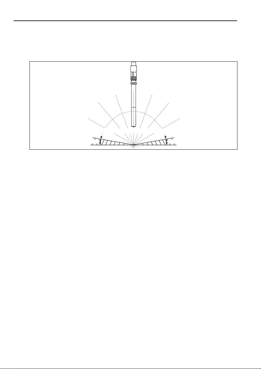
Fig. 1: Permitted installation angle
The sensor must be installed with an angle of inclination of at least 10 ° to the horizontal in an
assembly, support or a suitable process connection. Other angles are not permissible. Do not
install the sensor overhead.
Note!
!
Make sure you comply with the instructions for installing sensors. You will find them in the
Operating Instructions for the assembly used.
2.2.2 Mounting location
• Select the installation location so that there is easy access for later calibration.
• Make sure that upright posts and assemblies are secured safely and vibration-free.
• For immersed operation in an activated sludge basin, select an installation location which
produces a typical oxygen concentration.
10° 10°
Not permissible!
2.3 Installation instructions
2.3.1 Measuring system
A complete measuring system comprises:
• Oxygen sensor COS21
• Transmitter, e.g. Liquisys M COM223/253 F
• Special measuring cable COK21
• Assembly, e.g. retractable assembly CPA475
a0006654-en
4 Endress+Haus er
Page 5
Oxymax H COS21 Installation
CAL REL
REL1
REL1
ALARM
REL2
REL2
E
3
2
1
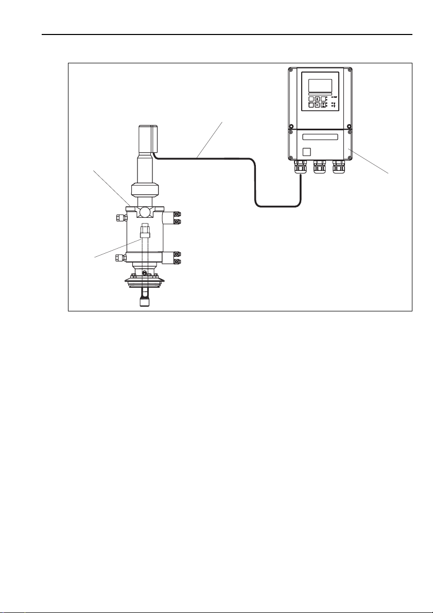
Fig. 2: Measuring system (example)
1 Oxygen sensor COS21
2 Retractable assembly CPA475
3 Special measuring cable COK21
4 Transmitter Liquisys M COM253 F
2.3.2 Installing a measuring point
For a complete installation of a measuring point, proceed as follows:
1. Install a retractable or a flow assembly (if used) into the process.
2. Connect the water supply to the rinse connections (if you use an assembly with cleaning
function).
3. Install and connect the oxygen sensor.
Caution!
"
• Do not install the sensor suspended from the cable.
• Screw the sensor into the assembly so that the cable is not twisted.
• Avoid exerting excessive tensile force on the cable (e.g. from jerky pulling).
• Select the installation location so that there is easy access for later calibration.
4
a0006653
Endress+Hauser 5
Page 6
Wiring Oxymax H COS21
Warning!
#
When using metallic assemblies and installation equipment, comply with national grounding
regulations.
2.4 Post-installation check
• Sensor and cable undamaged?
• Cap undamaged?
• Compliance with permissible sensor installation position?
• Is the sensor installed in an assembly and is not suspended from the cable?
• Avoid moisture by rain by fitting the protective cap to the immersion assembly?
3 Wiring
Warning!
#
• The electrical connection must only be carried out by a certified electrician.
• Technical personnel must have read and understood the instructions in this manual and must
adhere to them.
• Ensure that there is no voltage at the power cable before beginning the connection work.
3.1 Connection to Liquisys M COM223/253 F
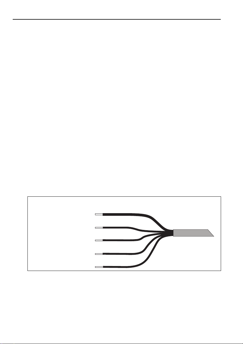
The electrical connection between the sensor and the transmitter uses the multi-core special
measuring cable COK21.
Assignment Terminal
External shield
Active internal shield
(NTC temp. sensor)
Cathode
Anode
NTC temp. sensor
Fig. 3: Special measuring cable COK21
S
12
90
91
11
GN / YE
YE
PK
BN
BU
a0005583-en
6 Endress+Haus er
Page 7
Oxymax H COS21 Commissioning
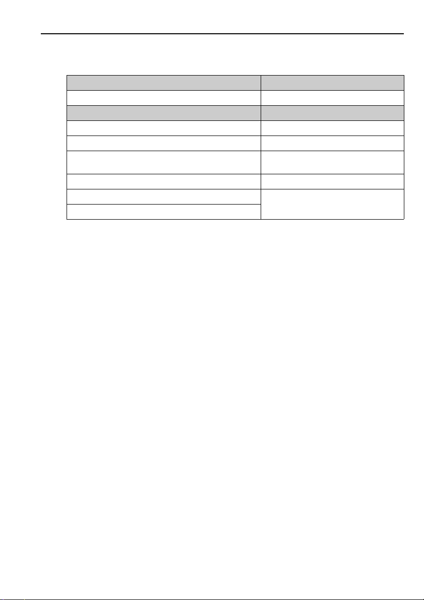
3.2 Post-connection check
Instrument status and specifications Remarks
Are the sensor, assembly, junction box or cable damaged? Visual inspection
Electrical connection Remarks
Are the installed cables strain-relieved and not twisted ?
Is the cable type route completely isolated ? Power cable/weak current cable
Are the power supply and signal cable correctly connected to the
transmitter ?
Are all the screws terminals properly tightened ? Tighten
Are all the cable entries installed, tightened and sealed ? For cable entries lateral: cable loops downwards
Are all the cable entries installed downwards or lateral ?
Use the connection diagram of the transmitter.
for water to be able to drip off.
4 Commissioning
4.1 Function check
Before first commissioning, check if:
• the sensor is correctly installed
• the electrical connection is correct.
If using an assembly with automatic cleaning, check the correct water connection at the
assembly rinse connection.
Warning!
#
Danger of medium leaking off
Before applying compressed air to an assembly with cleaning facility, make sure the connections
are correctly fitted. Otherwise, the assembly may not be insert into the process.
4.2 Polarization
The sensor was tested in the factory for perfect functionality and is supplied ready for operation.
To prepare for calibration, proceed as follows:
1. Remove the sensor protective cap.
2. Place the externally dry sensor in atmospheric air. The air should be saturated with water
vapour. Therefore, install the sensor as close to the water surface as possible. When
calibrating the sensor membrane, make sure the membrane remains dry. Therefore, avoid
any direct contact with the water surface.
3. Connect the sensor to the transmitter and switch on the transmitter.
Endress+Hauser 7
Page 8

Maintenance Oxymax H COS21
4. Switch-on the transmitter.
If you connect the sensor to the transmitter, polarization is automatically performed after
switching on the transmitter.
5. Wait for the polarization time to end.
Caution!
"
• When you remove the sensor from the medium, protect the sensor from strong sunlight.
• Make sure you comply with the instructions for commissioning and calibration in the
Operating Instructions of the transmitter.
4.3 Calibration
Calibrate the sensor (air calibration) immediately after the polarization time has elapsed.
The calibration intervals depend heavily on:
• The application and
• The installation position of the sensor.
The following methods help you determine how long the calibration intervals should be:
1. Check the sensor one month after its being put into operation by taking it out of the fluid,
drying it and then measuring the oxygen saturation index at air after 10 minutes.
Decide using the results:
a. If the measured value is not at 102±2%SAT, you have to calibrate the sensor.
b. Otherwise, double the length of time to the next inspection.
2. Proceed as per Point 1 after two, four and/or eight months. In this way, you can determine
the optimum calibration interval for your sensor.
Note!
!
Be sure to calibrate the sensor at least once a year.
5 Maintenance
Maintenance work must carried out at regular intervals. To ensure that it is carried out, we
recommend you enter the maintenance dates into an operations logbook or in an
operations calendar in advance.
The maintenance cycle primarily depends on the system, the installation conditions and the
medium in which measurement is taking place.
The following activities must be carried out:
• Cleaning the sensor
(In particular when the membrane is soiled)
• Check the measuring function:
1. Remove the sensor from the medium.
8 Endress+Haus er
Page 9
Oxymax H COS21 Maintenance
2. Clean and dry the membrane.
3. After about 10 minutes, measure the oxygen saturation index in air (without
recalibration).
4. The measured value should be near to 102% SAT.
• If necessary, replace a defective membrane or one which cannot be cleaned any more.
• Recalibration.
(if desired or required)
5.1 Cleaning the sensor
To ensure reliable measurement, the sensor must be cleaned at regular intervals. The frequency
and intensity of the cleaning operation depend on the measuring medium.
Clean the sensor:
• before every calibration
• at regular intervals during operation as necessary
• before returning it for repairs.
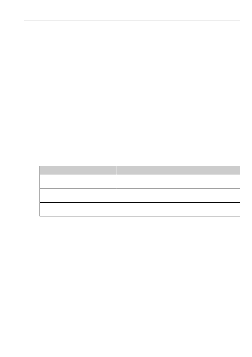
Depending on the type of soiling, proceed as follows:
Type of soiling Cleaning
Salt deposits Immerse the sensor in drinking water or in 1-5% hydrochloric acid
Dirt particles on the sensor body
(not cap!)
Dirt particles on the membrane cap or the
membrane
for a few minutes. Afterwards, rinse it with copious amounts of water.
Clean the sensor body mechanically with water and a suitable brush.
Clean with water and a soft sponge.
Caution!
"
After cleaning, rinse the sensor with copious amounts of clean water.
5.2 Regenerating the sensor
5.2.1 Replacing the sealing ring
Replacing the sealing ring is only necessary when it is visibly damaged. For replacement, use only
original sealing rings.
5.2.2 Replacing the electrolyte
Warning!
#
Risk of acid burns!
The electrolyte is very caustic. You must follow the appropriate occupational safety regulations.
Always wear protective gloves and goggles with handling electrolytes.
Endress+Hauser 9
Page 10

Maintenance Oxymax H COS21
To replace the electrolyte, proceed as follows:
1. Remove the membrane cap.
2. Replace the electrolyte and, if necessary, the membrane cap.
3. Place the membrane cap back on the sensor and screw the cap closed to the stop.
5.2.3 Replacing the membrane cap
Removing the old membrane cap
1. Remove the sensor from the medium.
2. Clean the outside of the sensor.
3. Unscrew the membrane cap.
4. If necessary, clean the cathode or replace the sealing ring if it is damaged.
5. Rinse the electrode holder with drinking water.
Installing the new membrane cap
1. Make sure that there are no dirt particles on the sealing surface.
2. Using the pipette supplied, fill approx. 1.5 ml (0.05 fl.oz.) of electrolyte into the membrane
cap.
3. Hold the sensor body straight and carefully screw the membrane cap onto it until the
stop.
Note!
!
After replacing the membrane cap, polarize and recalibrate the sensor. Then insert the sensor
into the medium and check that no alarm is displayed on the transmitter.
10 Endress+Haus er
Page 11

Page 12

BA244C/07/en/09.06
Printed in Germany / FM+SGML 6.0 /
DT
www.endress.com/worldwide
71032330
 Loading...