

Endress+Hauser Liquiphant M with FEL56, Liquiphant S with FEL56, Nivotester FTL325N-**** Series, Nivotester FTL325N Functional Safety Manual
Page 1

Products Solutions Services
SD00188F/00/EN/13.13
71238762
Functional safety manual
Liquiphant M/S with FEL56
and Nivotester FTL325N
Level Limit Measuring System
[Ex ia]
CH1
CH1
FTL325N
T
[Ex ia]
CH1 CH2
CH3
CH1 CH2CH3
T
FTL325N
Application
Minimum detection (also dry running protection) of all
types of liquids in tanks to satisfy particular safety systems
requirements as per IEC 61508/IEC 61511-1.
The measuring device fulfils the requirements concerning
• Safety functions up to SIL 2
• Explosion protection by intrinsic safety or flameproof
enclosure
• EMC to EN 61326 and NAMUR Recommendation
NE 21.
Your benefits
• For minimum detection up to SIL 2
– Independently assessed (Functional Assessment) by
exida.com as per IEC 61508/IEC 61511-1
• Monitoring for corrosion on the tuning fork of the
sensor
• No calibration
• Fault message for circuit break and short-circuit
• Functional test of subsequent devices at the push
of a button
• Protected against outside vibration
• Easy commissioning
Page 2

Liquiphant M/S with FEL56 and Nivotester FTL325N
2 Endress+Hauser
Table of contents
SIL declaration of conformity . . . . . . . . . . . . . . . . . . . . .3
Introduction . . . . . . . . . . . . . . . . . . . . . . . . . . . . . . . . . . . .4
General depiction of a safety system (protection function) . . . 4
Structure of the measuring system . . . . . . . . . . . . . . . .5
Level limit measuring system . . . . . . . . . . . . . . . . . . . . . . . . . . . . 5
Safety function . . . . . . . . . . . . . . . . . . . . . . . . . . . . . . . . . . . . . . . . 5
Permitted device types . . . . . . . . . . . . . . . . . . . . . . . . . . . . . . . . . 6
Safety function data . . . . . . . . . . . . . . . . . . . . . . . . . . . . . . . . . . . 7
Supplementary device documentation . . . . . . . . . . . . . . . . . . . . 7
Settings and installation instructions . . . . . . . . . . . . . .9
Installation instructions . . . . . . . . . . . . . . . . . . . . . . . . . . . . . . . . 9
Response in operation and failure . . . . . . . . . . . . . . . 10
Recurrent function tests of the measuring system . 10
Appendix . . . . . . . . . . . . . . . . . . . . . . . . . . . . . . . . . . . . 11
Specific values and wiring options for the
measuring system . . . . . . . . . . . . . . . . . . . . . . . . . . . . . . . . . . . . 11
Exida Management Summary . . . . . . . . . . . . . . . . . . . 18
Supplementary Documentation . . . . . . . . . . . . . . . . . . . . . . . . . 20
Page 3

Liquiphant M/S with FEL56 and Nivotester FTL325N
Endress+Hauser 3
SIL declaration of conformity
SIL-04001B-00-A2
Page 4

Liquiphant M/S with FEL56 and Nivotester FTL325N
4 Endress+Hauser
Introduction
General depiction of a
safety system
(protection function)
Parameter tables for determining Safety Integrity Level (SIL)
The following tables are used to define the reachable SIL or the requirements pertaining to the
“Average Probability of Dangerous Failure on Demand” (PFDav), the “Hardware Fault Tolerance” (HFT)
and the “Safe Failure Fraction” (SFF) of the safety system. The specific values for the Liquiphant M/S +
Nivotester FTL325N measuring system can be found in the Appendix.
Permitted probabilities of dangerous failures on demand of the complete safety related system
dependent on the SIL (e.g. exceeding a defined MIN level/switch point) (Source: IEC 61508, Part 1):
The following table shows the achievable Safety Integrity Level (SIL) as a function of the probability
fraction of safety-oriented failures and the "hardware fault tolerance" of the complete safety system for
type B systems (complex components, not all faults are known or can be described).
For general informationen about SIL please refer to: www.endress.com/sil
SIL PFD
av
4 10
5
to < 10
4
3 104 to < 10
3
2 103 to < 10
2
1 102 to < 10
1
SFF HFT
0 1 (0)
1)
1) In accordance with IEC 61511-1 (FDIS) (chapter 11.4.4), the HFT can be reduced by one (values in brackets)
if the devices used fulfil the following conditions:
- The device is proven in use,
- Only process-relevant parameters can be changed at the device (e.g. measuring range, ...),
- Changing the process-relevant parameters is protected (e.g. password, jumper, ...),
- The safety function requires less than SIL 4.
All conditions apply to Liquiphant M/S + Nivotester FTL325N.
2 (1)
1
< 60% not allowed SIL 1 SIL 2
60% to < 90% SIL 1 SIL 2 SIL 3
90% to < 99% SIL 2 SIL 3
99% SIL 3
Page 5
Liquiphant M/S with FEL56 and Nivotester FTL325N
Endress+Hauser 5
Structure of the measuring system
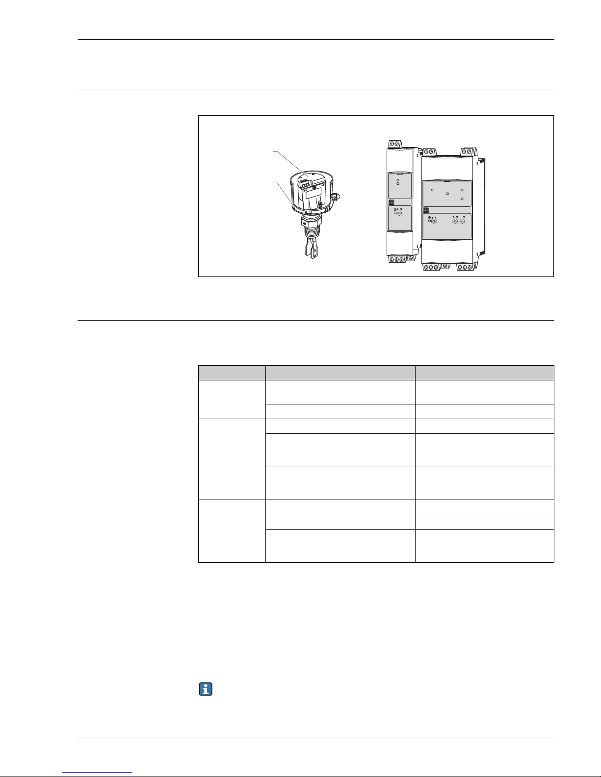
Level limit measuring system The measuring system's devices are displayed in the following diagram (example).
A0022173
1 FEL - Electronic insert A Nivotester FTL325N (one-channel)
2 Liquiphant M/S B Nivotester FTL325N (three-channel)
Safety function The safety function applies to all settings in MIN safety (monitoring of the covered state) and use of
the NO contacts of the level relays.
The following settings are permitted for the safety function:
The level relay always works in quiescent current safety; i.e. the relay releases when:
• The switch point is undershot (level falls below response height)
• A detected fault occurs
• The mains voltage fails
In addition to the level relay, the alarm relay works in quiescent current safety and releases when:
• One of the following faults occurs:
– the sensor connection is interrupted
– the sensor connection short circuits
• The mains voltage fails
[Ex ia]
CH1
CH1
FTL325
T
[Ex ia]
CH1 CH2
CH3
CH1 CH2 CH3
T
FTL325
AB
1
2
Device Setting As-delivered state
Liquiphant • Density switch setting: 0,5
• Density switch setting: 0,7
Density switch setting: 0,7
"MIN" safety "MAX" safety
Nivotester
FTL325N-#3#3
Error current signal > 2,1 mA Error current signal > 2,1 mA
All settings except
"S function" (see section "Settings and installation instructions")
Three-channel operation
The DIL switch for fault messaging
(short-circuit-, and circuit break-monitoring)
must be set to the ON position.
Failure switch "ON"
Nivotester
FTL325N-#1#1
Error current signal > 2,1 mA Error current signal > 2,1 mA
One-channel operation
The DIL switch for fault messaging
(short-circuit-, and circuit break-monitoring)
must be set to the ON position.
Failure switch "ON"
When the alarm relay releases, the level relay also releases.
Page 6

Liquiphant M/S with FEL56 and Nivotester FTL325N
6 Endress+Hauser
Permitted device types The details pertaining to functional safety in this manual relate to the device versions listed below and
are valid as of the specified firmware and hardware version.
Unless otherwise specified, all subsequent versions can also be used for safety instrumented systems.
A modification process according to IEC 61508 is applied for device changes.
Valid device versions for safety-related use:
Valid firmware version: as of 01.00.00
Valid hardware version (electronics): as of 01.00
Valid device versions for safety-related use:
Valid firmware version: as of 01.00.00
Valid hardware version (electronics): as of 01.00
Valid device versions for safety-related use:
Liquiphant M FTL50, FTL50H, FTL51, FTL51C, FTL51H+ FEL56
Feature Designation Option model
010 Approval all
020 Process connection all
030 Probe length; Type all
040 Electronics; Output 6 FEL56; SIL NAMUR (L-H signal)
050 Housing; Cable Entry all
060 Additional options all
Liquiphant S FTL70, FTL71+ FEL56
Feature Designation Option model
010 Approval all
020 Process connection all
030 Probe length all
040 Electronics; Output 6 FEL56; SIL NAMUR (L-H signal)
050 Housing; Cable entry all
060 Additional option all
070 Application all
Nivotester FTL325N
Feature Designation Option model
010 Approval G
H
N
P
T
W
ATEX II 3(1)G Ex nC/A (ia) IIC T4, SIL, IECEx Zone 2
ATEX II (1)GD (Ex ia) IIC, WHG, SIL, IECEx (Ex ia) IIC
(Liquiphant M / Liquiphant S)
NEPSI (Ex ia) IIC, SIL (Liquiphant M / Liquiphant S)
FM IS Cl. I, II, III Div. 1 Gr. A-G, SIL (Liquiphant M / Liquiphant S)
CSA IS Cl. I, II, III Div. 1 Gr. A-G, SIL (Liquiphant M / Liquiphant S)
TIIS Ex ia IIC, SIL, labeling in Japan
020 Housing all
030 Power Supply all
040 Switch output all
Page 7

Liquiphant M/S with FEL56 and Nivotester FTL325N
Endress+Hauser 7
Safety function data •The mandatory settings and data for the safety function can be found in chapter "Safety function",
ä 5 and chapter "Settings and installation instructions", ä 9.
• The measuring system reacts in 1,4 s.
Supplementary
device documentation
MTTR is set at eight hours.
Safety systems without a self-locking function must be monitored or set to an otherwise safe
state after carrying out the safety function within MTTR.
Liquiphant M FTL50, FTL50H, FTL51, FTL51H, FTL51C
Documentation Contents Comment
Technical Information
• FTL50, FTL50H, FTL51,
FTL51H:
TI00328F/00/EN
•FTL51C:
TI00347F/00/EN
–Technical data
– Accessories
– The documentation is available on the
Internet:
www.endress.com.
Operating Instructions
•FTL50, FTL51:
KA00143F/00/A6
KA00163F/00/A6
1)
• FTL50H, FTL51H:
KA00144F/00/A6
KA00164F/00/A6
)
•FTL51C:
KA00162F/00/A6
KA00165F/00/A6
)
1) with aluminium housing / separate terminal compartment.
– Installation
– Wiring
–Operation
– Commissioning
– Troubleshooting
– Repair
–Maintenance
– The documentation is supplied with the
device.
– The documentation is also available on
the Internet:
www.endress.com.
Safety instructions depending
on the selected version
"Approval"
Safety, installation and
operating instructions for devices,
which are suitable for use in
potentially explosive atmospheres
or as overfill
protection (WHG, German Water
Resources Act).
Additional safety instructions (XA, ZE) are
supplied with certified device versions.
Please refer to the nameplate for the relevant safety instructions.
Liquiphant S FTL70, FTL71
Documentation Contents Comment
Technical Information
TI00354F/00/EN
–Technical data
– Accessories
– The documentation is available on the
Internet:
www.endress.com.
Operating Instructions
KA00172F/00/A6
KA00173F/00/A6
1)
1) with aluminium housing / separate terminal compartment
– Installation
– Wiring
–Operation
– Commissioning
– Troubleshooting
– Repair
–Maintenance
– The documentation is supplied with the
device.
– The documentation is also available on
the Internet:
www.endress.com.
Safety instructions depending
on the selected version
"Approval"
Safety, installation and
operating instructions for devices,
which are suitable for use in
potentially explosive atmospheres
or as overfill
protection (WHG, German Water
Resources Act).
Additional safety instructions (XA, ZE) are
supplied with certified device versions.
Please refer to the nameplate for the relevant safety instructions.
Page 8

Liquiphant M/S with FEL56 and Nivotester FTL325N
8 Endress+Hauser
Nivotester FTL325N
Documentation Contents Comment
Technical Information
TI00353F/00/EN
–Technical data
– Accessories
– The documentation is available on the
Internet:
www.endress.com.
Operating Instructions
• One-channel device:
KA00170F/00/A6
• Three-channel device:
KA00171F/00/A6
– Installation
– Wiring
–Operation
– Commissioning
– Troubleshooting
– Repair
–Maintenance
– The documentation is supplied with the
device.
– The documentation is also available on
the Internet:
www.endress.com.
Safety instructions depending
on the selected version
"Approval"
Safety, installation and
operating instructions for devices,
which are suitable for use in
potentially explosive atmospheres
or as overfill
protection (WHG, German Water
Resources Act).
Additional safety instructions (XA, ZE) are
supplied with certified device versions.
Please refer to the nameplate for the relevant safety instructions.
Page 9
Liquiphant M/S with FEL56 and Nivotester FTL325N
Endress+Hauser 9
Settings and installation instructions
Installation instructions Please refer to the Compact Instructions (KA) for information regarding the correct installation of
Liquiphant M/S + Nivotester FTL325N.
Since the application conditions have an effect on the safety of the measurement, pay attention to the
notes in the Technical Information (TI) and Compact Instructions (KA).
The ambient conditions for the Nivotester FTL325N must correspond to IP54 (in accordance with
EN 60529).
The manuals on setting the devices can be found in the section "Supplementary device documentation",
ä 7.
Settings for Liquiphant M/S (FEL56):
•The density switch setting must be configured according to the density range of the medium.
• The settings of the safety mode has an effect on the function. The DIL switch must be set to MIN for
minimum detection in a SIL application.
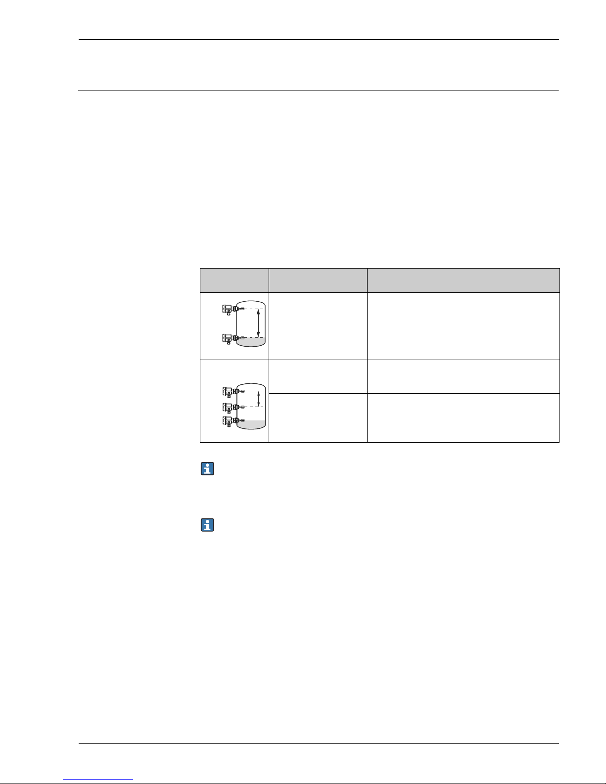
Settings for Nivotester FTL325N-#3#3 (three-channel version):
Setting Description
"
Caution!
A0022176
Channel 2+3 in
S function
This setting ist not permitted for the safety function!
A0022177
Channel 1, independent Channel 1 is permitted for the safety function. The DIL
switch for fault messaging (short-circuit and cable
break-monitoring) must be set into possition ON.
Channel 2+3 in
S function
Channel 2 and 3 in this setting are not permitted for the
safety function!
Observe the following for the Nivotester FTL325N-####: The operator must use suitable
measures (e.g. current limiter, fuse) to ensure the relay contact characteristics are not exceeded:
•U 253 V AC 50/60 Hz , I 2 A, P 500 VA at cos 0,7 or
•U 40 V DC, I 2 A, P 80 W
Changes to the measuring system and settings after start-up can impair the protection function!
CH3
D
s
CH2
CH1
D
s
CH3
CH2
Page 10

Liquiphant M/S with FEL56 and Nivotester FTL325N
10 Endress+Hauser
Response in operation and failure
The response in operation and failure is descriped in the documentation, which can be found in the
section "Supplementary device documentation", ä 7.
Repair In the event of failure of a SIL-labeled Endress+Hauser device, which has been operated in a protection
function, the "Declaration of Contamination and Cleaning" with the corresponding note "Used as SIL
device in protection system" must be enclosed when the defective device is returned
Recurrent function tests of the measuring system
The operativeness of the minimum detection must be checked annually if the PFDav values given in the
Appendix are used.
The check must be carried out in such a way that it is proven that the minimum detection functions
perfectly in interaction with all components. This is guaranteed when the response height is lowered
in an emptying process. If it is not practical to empty to the response height, suitable simulation of the
level or of the physical measuring effect must be used to make the level sensor respond.
If the operativeness of the level sensor/transmitter can be determined otherwise (exclusion of faults
that impair function), the check can also be completed by simulating the corresponding output signal.
In the case of recurrent tests, each permitted setting must be checked, especially whether all the alarm
switches are set to ON.
Note the following points for the function test:
• Each individual channel must be checked e.g. by lowering the level.
• Relay contact switching can be checked by using a hand multimeter at the terminals or by
observing the minimum detection components (e.g. horn, adjuster).
• In multi-channel devices, all channels which do not carry out a safety function must be
included in the recurrent function tests if faulty functioning cannot be detected by any other
means.
• As a positive test result, an uncovered tuning fork must be detected and trigger the alarm for
minimum detection.
• If fork uncovering is not detected during the recurrent test, the monitored process must
be set to a safe state by means of additional or other measures and/or kept in the safe
state until the safety system is repaired.
Page 11

Liquiphant M/S with FEL56 and Nivotester FTL325N
Endress+Hauser 11
Appendix
Specific values and
wiring options for the
measuring system
The tables show the specific values and wiring options for the measuring system.
Note the following points on the tables below:
•The PFDav values for multichannel systems already contain common cause failures for the
associated wiring scheme.
•The PFDav values are only valid for the associated wiring scheme. Wiring schemes other than
those shown in the Appendix were not assessed and thus do not bear any information relevant
to safety. Using NC contacts instead of NO contacts requires further consideration of the
installation means.
• The wiring scheme shows the number of devices (Liquiphant and Nivotester) and the limit
relay contact circuits (open, when the sensor signals uncovering).
• Fault messaging (circuit break/short-circuit) must be switched on for each channel that
performs a safety function.
• With several devices in a wiring scheme, they all indicate the same displayed settings.
For safety related use of the Liquiphant M/S for MIN detection, the following application errors
must be excluded:
• Permanent and/or heavy build-up or "non-Newtonian media"
• Solid proportions of the medium with a diameter > 5,0 mm (0.2 in)
• Corrosion: The Liquiphant may only be used in media to which the process-wetted parts are
resistant. If coated sensors are used, measures must therefore be taken to ensure that there is
no damage during installation and operation.
The errors may cause that the demand mode of the safety function is not detected and the
Liquiphant will not switch as intended.
Page 12
Liquiphant M/S with FEL56 and Nivotester FTL325N
12 Endress+Hauser
A0022344-EN
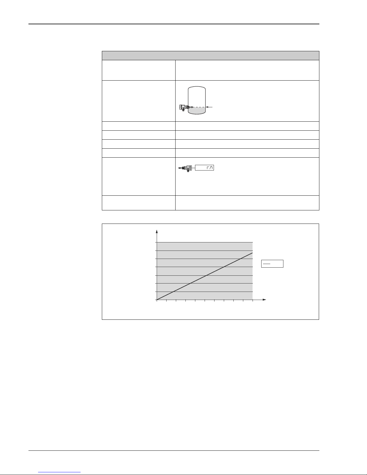
1oo1 architecture (CONF 1)
Liquiphant (FEL56)
Settings 1) Density 0,7 / 0,5
2) MIN safety
Evaluated NAMUR transmitter
A0022180
Error current signal
> 2,1 mA
SIL SIL 2
HFT 0
SFF 78%
PFD
av
** 0,029 x 10
-2
Wiring scheme
A0022181
Ask the manufacturer in question for the NAMUR transmitter parameters
relevant to safety.
Recurrent test
e.g. lowering the level
** TI (test interval) = annual
CH1
0,0 2,0 4,0 6,0 8,0 10,0
3,00E-03
3,50E-03
2,50E-03
2,00E-03
1,00E-03
5,00E-04
0,00E+00
1,50E-03
PFD
PFD
avg
1oo1D structure
Test interval
[years]
Page 13
Liquiphant M/S with FEL56 and Nivotester FTL325N
Endress+Hauser 13
A0022345-EN
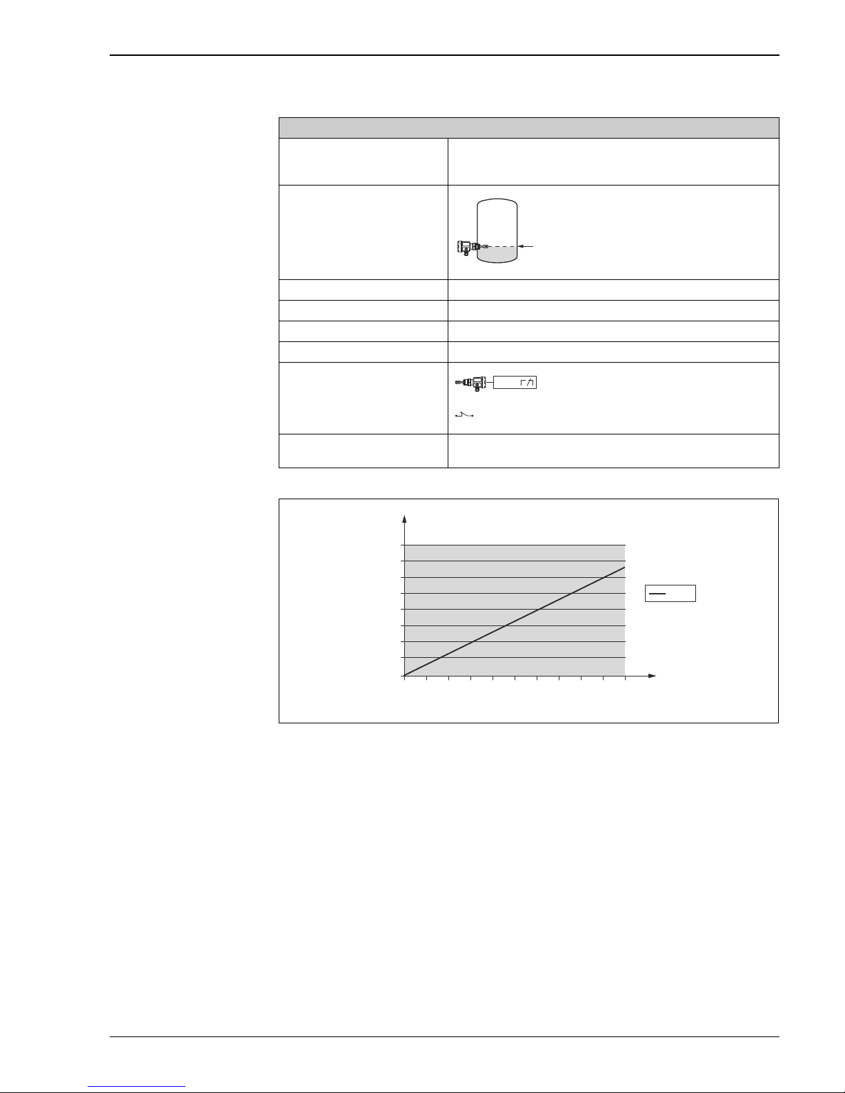
1oo1 architecture (CONF 2)
Liquiphant (FEL56)
Settings 1) Density 0,7 / 0,5
2) MIN safety
Nivotester FTL325N-#1#1
Settings
(One-channel device)
A0022180
Error current signal
> 2,1 mA
SIL SIL 2
HFT 0
SFF 88%
PFD
av
** 0,034 x 10
-2
Wiring scheme
A0022187
Recurrent test
e.g lowering the level
** TI (test interval) = annual
CH1
CH1:
0,0 2,0 4,0 6,0 8,0 10,0
3,00E-03
3,50E-03
4,00E-03
2,50E-03
2,00E-03
1,00E-03
5,00E-04
0,00E+00
1,50E-03
PFD
PFD
avg
Test interval
[years]
1oo1D structure
Page 14
Liquiphant M/S with FEL56 and Nivotester FTL325N
14 Endress+Hauser
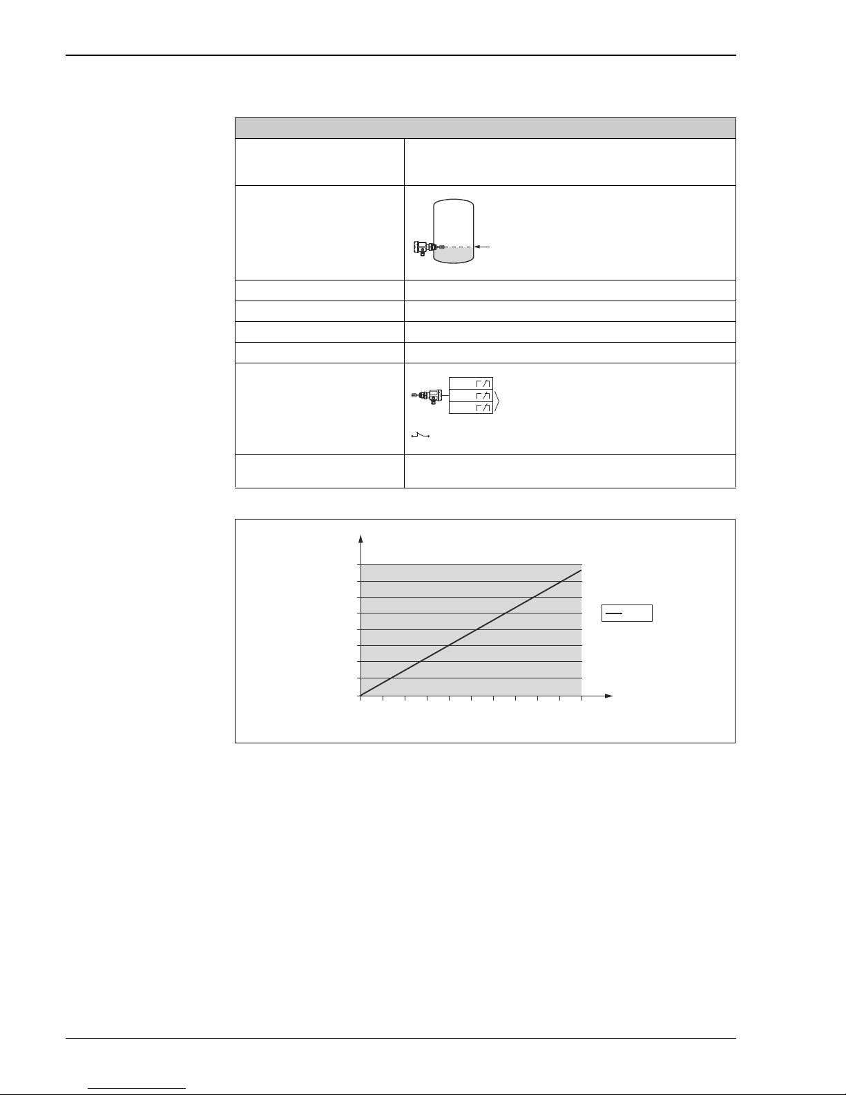
A0022346-EN
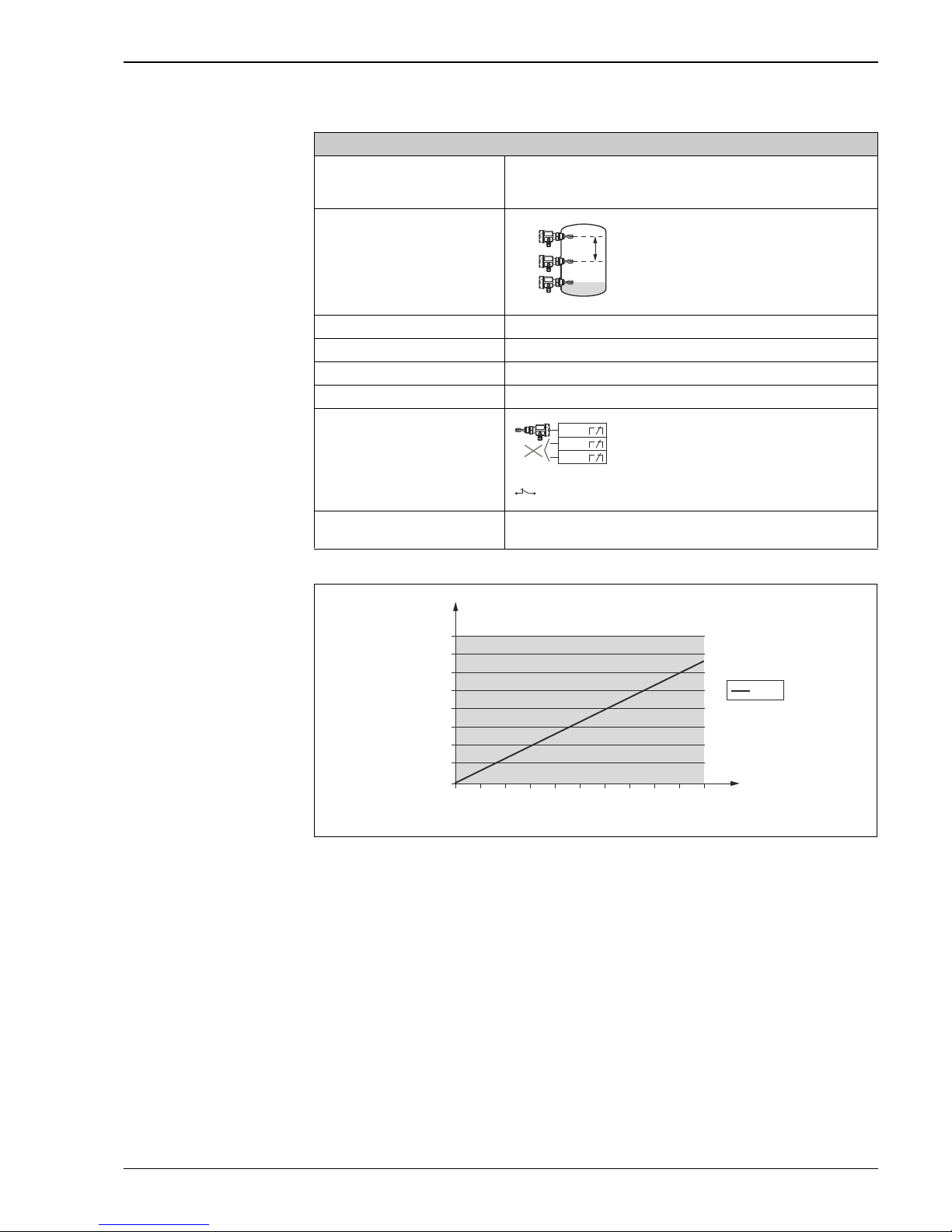
1oo1 architecture (CONF 3)
Liquiphant (FEL56)
Settings 1) Density 0,7 / 0,5
2) MIN safety
Nivotester FTL325N-#3#3
Settings
(Three-channel device)
A0022180
Error current signal
> 2,1 mA
SIL SIL 2
HFT 0
SFF 88%
PFD
av
** 0,038 x 10
-2
Wiring scheme
A0022193
Recurrent test
e.g. lowering the level
** TI (test interval) = annual
CH2
CH1
CH3
CH2, CH3:
0,0 2,0 4,0 6,0 8,0 10,0
3,00E-03
3,50E-03
4,00E-03
2,50E-03
2,00E-03
1,00E-03
5,00E-04
0,00E+00
1,50E-03
PFD
PFD
avg
Test interval
[years]
1oo1D structure
Page 15
Liquiphant M/S with FEL56 and Nivotester FTL325N
Endress+Hauser 15
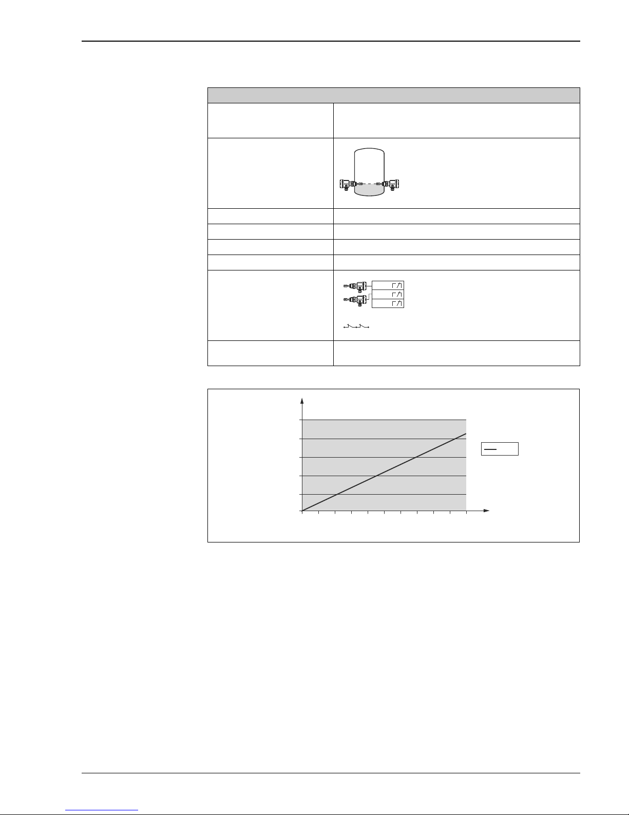
A0022347-EN
1oo2 architecture (CONF 4)
Liquiphant (FEL56)
Settings 1) Density 0,7 / 0,5
2) MIN safety
Nivotester FTL325N-#3#3
Settings
(Three-channel device)
A0022197
Error current signal
> 2,1 mA
SIL SIL 2
HFT 1
SFF 88%
PFD
av
** 0,0019 x 10
-2
Wiring scheme
A0022198
Recurrent test
e.g. lowering the level
** TI (test interval) = annual
CH2
CH1
CH3
CH1 + CH2
0,0 2,0 4,0 6,0 8,0 10,0
2,50E-04
2,00E-04
1,00E-04
5,00E-05
0,00E+00
1,50E-04
PFD
PFD
avg
Test interval
[years]
1oo2D structure
Page 16
Liquiphant M/S with FEL56 and Nivotester FTL325N
16 Endress+Hauser
A0022348-EN
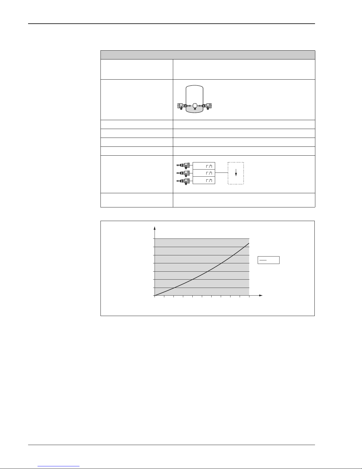
2oo3 architecture (CONF 5)
Liquiphant (FEL56)
Settings 1) Density 0,7 / 0,5
2) MIN safety
Nivotester FTL325N-#3#3
Settings
(Three-channel device)
A0022201
Error current signal
> 2,1 mA
SIL SIL 2
HFT 1
SFF 87%
PFD
av
** 0,0023 x 10
-2
Wiring scheme
A0022202
Recurrent test
e.g. lowering the level
** TI (test interval) = annual
CH2
CH1
CH3
SPS
2oo3
0,0 2,0 4,0 6,0 8,0 10,0
3,00E-04
3,50E-04
2,50E-04
2,00E-04
1,00E-04
5,00E-05
0,00E+00
1,50E-04
PFD
PFD
avg
2oo3D structure
Test interval
[years]
Page 17
Liquiphant M/S with FEL56 and Nivotester FTL325N
Endress+Hauser 17
A0022345-EN
1oo1 achitecture (CONF 6)
Liquiphant (FEL56)
Settings 1) Density 0,7 / 0,5
2) MIN safety
Nivotester FTL325N-#3#3
Settings
(Three-channel device)
A0022204
Error current signal
> 2,1 mA
SIL SIL 2
HFT 0
SFF 88%
PFD
av
** 0,034 x 10
-2
Wiring scheme
A0022205
Recurrent test
e.g. lowering the level
** TI (test interval) = annual
CH1
D
s
CH3
CH2
CH2
CH1
CH1:
CH3
SIL
0,0 2,0 4,0 6,0 8,0 10,0
3,00E-03
3,50E-03
4,00E-03
2,50E-03
2,00E-03
1,00E-03
5,00E-04
0,00E+00
1,50E-03
PFD
PFD
avg
Test interval
[years]
1oo1D structure
Page 18
Liquiphant M/S with FEL56 and Nivotester FTL325N
18 Endress+Hauser
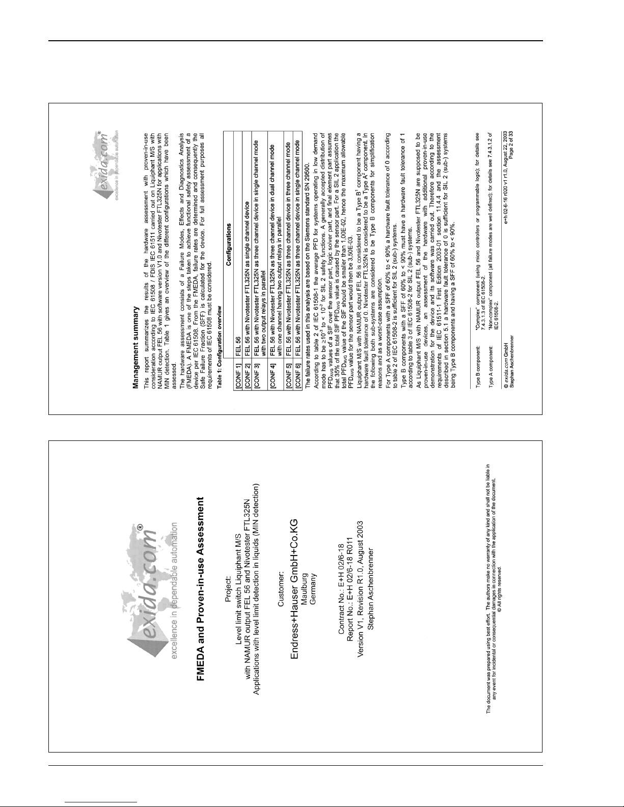
Exida Management Summary
Exida Management Summary 2
Exida Management Summary 1
Page 19
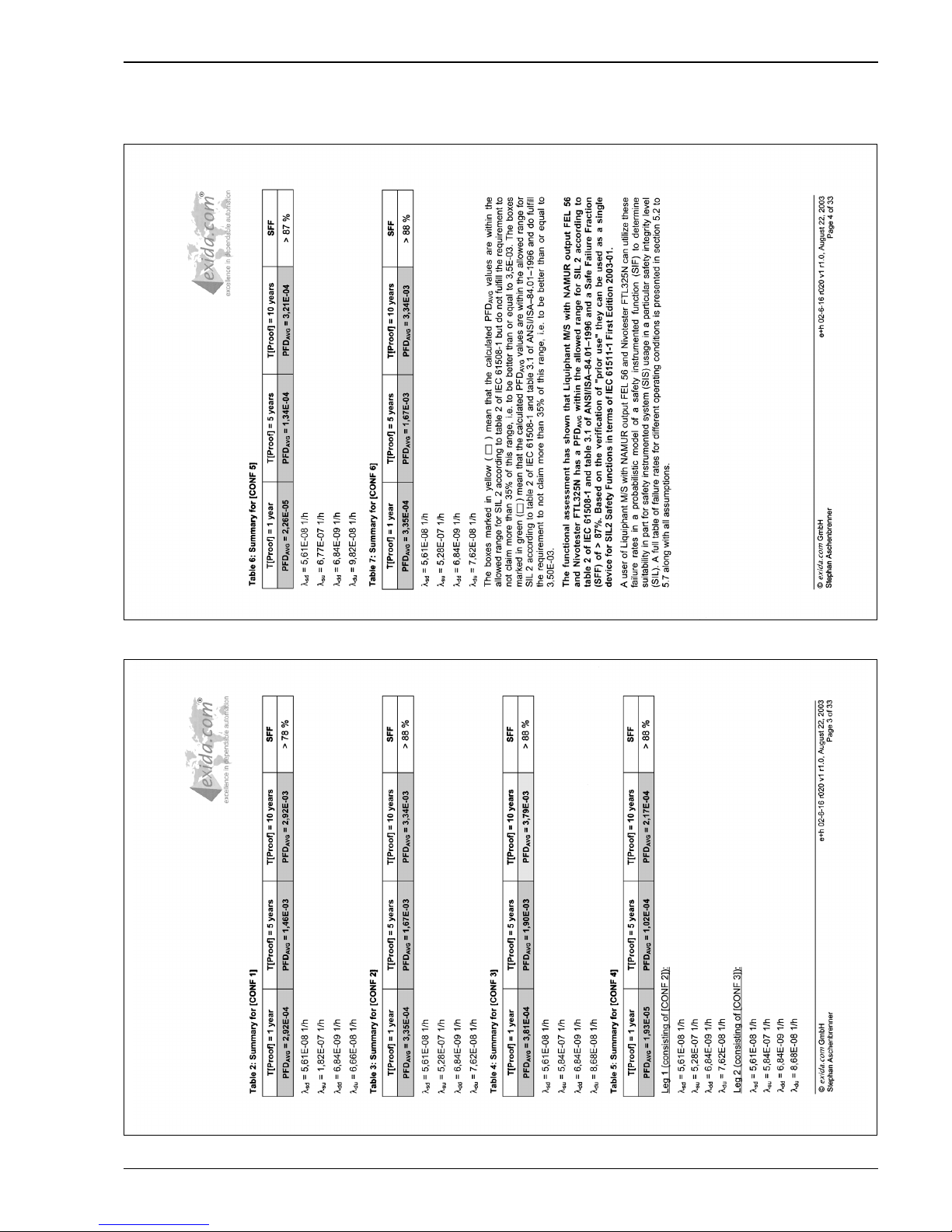
Liquiphant M/S with FEL56 and Nivotester FTL325N
Endress+Hauser 19
Exida Management Summary 4
Exida Management Summary 3
Page 20

Liquiphant M/S with FEL56 and Nivotester FTL325N
20 Endress+Hauser
Supplementary
Documentation
Safety in the Process Industry - reducing risks with SIL
CP01008Z/11/EN.
Page 21

Liquiphant M/S with FEL56 and Nivotester FTL325N
Endress+Hauser 21
Page 22

Liquiphant M/S with FEL56 and Nivotester FTL325N
22 Endress+Hauser
Page 23

Liquiphant M/S with FEL56 and Nivotester FTL325N
Endress+Hauser 23
Page 24

www.addresses.endress.com
71238762
 Loading...