

Endress+Hauser Oxymax COS22 Series, Oxymax COS22Z, Oxymax COS22D Operating Instructions Manual

BA00446C/07/EN/04.15
71306871
Products Solutions Services
Operating Instructions
Oxymax COS22
Analog sensor for the measurement of dissolved oxygen

Table of contents
Table of contents
1 Document information .............. 3
1.1 Warnings ............................ 3
1.2 Symbols .............................. 3
2 Basic safety instructions ............ 4
2.1 Requirements for personnel ............... 4
2.2 Designated use ........................ 4
2.3 Occupational safety ..................... 4
2.4 Operational safety ...................... 5
2.5 Product safety ......................... 5
3 Device description, function ......... 6
3.1 Amperometric measuring principle .......... 6
3.2 Sensor design ......................... 6
3.3 Membrane body ....................... 6
3.4 Polarization ........................... 6
4 Incoming acceptance and product
identification ....................... 7
4.1 Incoming acceptance .................... 7
4.2 Product identification .................... 7
4.3 Scope of delivery ....................... 8
4.4 Certificates and approvals ................ 8
10 Maintenance ...................... 22
10.1 Maintenance schedule .................. 22
10.2 Maintenance tasks ..................... 22
10.3 Clean sensor ......................... 23
10.4 Wear parts and consumables ............. 23
11 Accessories ....................... 26
11.1 Assemblies (selection) .................. 26
11.2 Measuring cable ...................... 26
11.3 Zero-point gel ........................ 26
11.4 Maintenance kit ...................... 27
12 Repair ............................ 28
12.1 Spare parts and consumables ............. 28
12.2 Return .............................. 28
12.3 Disposal ............................ 28
13 Technical data .................... 29
Index .................................. 34
5 Installation ........................ 9
5.1 Installation conditions ................... 9
5.2 Mounting the sensor ................... 10
5.3 Installation examples ................... 11
5.4 Post-installation check .................. 13
6 Electrical connection .............. 14
6.1 Connecting the sensor .................. 14
6.2 Ensuring the degree of protection .......... 14
6.3 Post-connection check .................. 14
7 Calibration and adjustment ........ 16
7.1 Types of calibration .................... 16
7.2 Calibration in air ...................... 16
7.3 Calculation example for the calibration
value ............................... 17
7.4 Zero point calibration ................... 18
8 Commissioning .................... 19
8.1 Function check ....................... 19
8.2 Sensor polarization .................... 19
8.3 Sensor calibration ..................... 20
9 Troubleshooting .................. 21
2 Endress+Hauser

Oxymax COS22 Document information
1 Document information
1.1 Warnings
Structure of information Meaning
DANGER
L
Causes (/consequences)
Consequences of non-compliance
(if applicable)
Corrective action
‣
WARNING
L
Causes (/consequences)
Consequences of non-compliance
(if applicable)
Corrective action
‣
CAUTION
L
Causes (/consequences)
Consequences of non-compliance
(if applicable)
Corrective action
‣
NOTICE
Cause/situation
Consequences of non-compliance
(if applicable)
Action/note
‣
This symbol alerts you to a dangerous situation.
Failure to avoid the dangerous situation will result in a fatal or serious
injury.
This symbol alerts you to a dangerous situation.
Failure to avoid the dangerous situation can result in a fatal or serious
injury.
This symbol alerts you to a dangerous situation.
Failure to avoid this situation can result in minor or more serious injuries.
This symbol alerts you to situations which may result in damage to
property.
1.2 Symbols
Symbol Meaning
Additional information, tips
Permitted or recommended
Not permitted or not recommended
Reference to device documentation
Reference to page
Reference to graphic
Result of a step
Endress+Hauser 3

Basic safety instructions Oxymax COS22
2 Basic safety instructions
2.1 Requirements for personnel
• Installation, commissioning, operation and maintenance of the measuring system may
be carried out only by specially trained technical personnel.
• The technical personnel must be authorized by the plant operator to carry out the
specified activities.
• The electrical connection may be performed only by an electrical technician.
• The technical personnel must have read and understood these Operating Instructions
and must follow the instructions contained therein.
• Measuring point faults may be repaired only by authorized and specially trained
personnel.
Repairs not described in the Operating Instructions provided may only be carried out
directly by the manufacturer or by the service organization.
2.2 Designated use
The oxygen sensor is suitable for continuous measurement of dissolved oxygen in water.
The specific suitability depends on the sensor design:
• COS22-*1 (standard, measuring range 0.01 to 60 mg/l)
– Measuring, monitoring and regulating the oxygen content in fermenters
– Monitoring the oxygen content in biotechnology facilities
• COS22-*3 (trace measurement, measuring range 0.001 to 10 mg/l, preferred
operational range 0.001 to 2 mg/l), also suitable for high CO2 partial pressure
– Monitoring inertization equipment in the food industry
– Monitoring the residual oxygen content in carbonated fluids of the beverage industry
– Trace measurement in industrial applications such as inertizations
– Monitoring the residual oxygen content in boiler feedwater
– Monitoring, measuring and regulating the oxygen content in chemical processes
NOTICE
Molecular hydrogen
Hydrogen causes sensitivity in other substances and leads to false low readings or, at the
worst, total failure of the sensor.
Only use the COS22-*1/3 sensor in media free of hydrogen.
‣
Use of the device for any purpose other than that described, poses a threat to the safety of
people and of the entire measuring system and is therefore not permitted.
The manufacturer is not liable for damage caused by improper or non-designated use.
2.3 Occupational safety
As the user, you are responsible for complying with the following safety conditions:
• Installation guidelines
• Local standards and regulations
• Regulations for explosion protection
Electromagnetic compatibility
• The product has been tested for electromagnetic compatibility in accordance with the
applicable European standards for industrial applications.
• The electromagnetic compatibility indicated applies only to a product that has been
connected in accordance with these Operating Instructions.
4 Endress+Hauser

Oxymax COS22 Basic safety instructions
2.4 Operational safety
1. Before commissioning the entire measuring point, verify that all connections are
correct. Ensure that electrical cables and hose connections are undamaged.
2. Do not operate damaged products, and safeguard them to ensure that they are not
operated inadvertently. Label the damaged product as defective.
3. If faults cannot be rectified:
Take the products out of operation and safeguard them to ensure that they are not
operated inadvertently.
2.5 Product safety
The product is designed to meet state-of-the-art safety requirements, has been tested, and
left the factory in a condition in which it is safe to operate. The relevant regulations and
European standards have been observed.
Endress+Hauser 5

Device description, function Oxymax COS22
1 2
3
4
5
78
9
6
3 Device description, function
3.1 Amperometric measuring principle
The oxygen molecules that diffuse through the membrane are reduced at the cathode to
hydroxide ions (OH-). At the anode, silver is oxidized to silver ions (Ag+) (this forms a
silver halide layer). A current flows due to the electron donation at the cathode and the
electron acceptance at the anode. Under constant conditions, this flow is proportional to
the oxygen content of the medium. This current is converted in the transmitter and
indicated on the display as an oxygen concentration in mg/l, µg/l, ppm, ppb or Vol%, as a
saturation index in % SAT or as an oxygen partial pressure in hPa.
3.2 Sensor design
A0011868
1 COS22
1
2
3
Plug-in head
Thrust collar
Sensor shaft
4
O-ring 8.5 x 1.5 mm
5
Membrane body
6
Shaft sleeve
7
Glass portion with anode and cathode
8
Process seal 10.77 x 2.62 mm
9
Process connection Pg 13.5
3.3 Membrane body
The oxygen dissolved in the medium is transported to the membrane by the necessary
flow. The membrane is permeable for dissolved gases only. Other substances dissolved in
the liquid phase, e.g. ionic substances, will not penetrate through the membrane.
Therefore, medium conductivity has no impact on the measuring signal.
The sensor is shipped with a standard membrane body, which can be used for all common
applications. The membrane is pretensioned at the factory and can be installed
immediately.
Electrolytes are version-specific and cannot be mixed in a single application!
3.4 Polarization
When the sensor is connected to the transmitter, a fixed voltage is applied between the
cathode and anode. The polarization current this creates can be identified on the
transmitter with a display that is initially high, but decreases with time. The sensor cannot
be calibrated until the display is calibrated.
Reference value for nearly complete polarization of a sensor that was previously stored for
a long time:
• COS22-*1: 2 hours
• COS22-*3: 12 hours
After this time, even measurements close to the determination limit are useful. The
necessary polarization time is reduced for sensors that were in use a short time before.
6 Endress+Hauser

Oxymax COS22 Incoming acceptance and product identification
4 Incoming acceptance and product
identification
4.1 Incoming acceptance
1. Verify that the packaging is undamaged.
Notify your supplier of any damage to the packaging.
Keep the damaged packaging until the matter has been settled.
2. Verify that the contents are undamaged.
Notify your supplier of any damage to the delivery contents.
Keep the damaged products until the matter has been settled.
3. Check the delivery for completeness.
Check it against the delivery papers and your order.
4. Pack the product for storage and transportation in such a way that it is protected
against impact and moisture.
The original packaging offers the best protection.
The permitted ambient conditions must be observed (see "Technical data").
If you have any questions, please contact your supplier or your local sales center.
4.2 Product identification
4.2.1 Nameplate
The nameplate provides you with the following information on your device:
• Manufacturer identification
• Order code
• Extended order code
• Serial number
• Safety information and warnings
Compare the data on the nameplate with your order.
4.2.2 Product identification
Product page
www.endress.com/cos22
Interpreting the order code
The order code and serial number of your product can be found in the following locations:
• On the nameplate
• In the delivery papers
Obtaining information on the product
1. Go to the product page for your product on the Internet.
2. In the navigation area on the right-hand side, select "Check your device features"
under "Device support".
An additional window opens.
3. Enter the order code from the nameplate into the search field.
You will receive information on each feature (selected option) of the order code.
Endress+Hauser 7

Incoming acceptance and product identification Oxymax COS22
4.3 Scope of delivery
The scope of delivery comprises:
• Oxygen sensor with watering cap (filled with tap water) for protecting the membrane
• Electrolyte, 1 bottle, 10 ml (0.34 fl.oz.)
• Tool to push out the membrane body
• Brief Operating Instructions
4.4 Certificates and approvals
4.4.1
Declaration of Conformity
The product meets the requirements of the harmonized European standards. As such, it
complies with the legal specifications of the EC directives. The manufacturer confirms
successful testing of the product by affixing to it the mark.
mark
4.4.2 Material certificates
Manufacturer declaration of FDA compatibility
The manufacturer declares the use of FDA-listed materials.
Ask your Sales Center for the certificates.
Product FDA certificate for
COS22-****22 Membrane, O-rings, process seal
COS22Z-*2*2 Membrane, O-rings, process seal
COS22-****23 Membrane, O-rings
COS22Z-*2*3 Membrane, O-rings
Material test certificate
A test certificate 3.1 in accordance with EN10204 is supplied depending on the version (→
Product Configurator on the product page).
EHEDG
Compliance with EHEDG's criteria for hygienic design
• TÜV Rheinland, Apeldorn, Netherlands
• Certificate type: Type EL Class I
8 Endress+Hauser

Oxymax COS22 Installation
10° 10°
Not permissible!
Not permissible!
Permissible angle of installation
5 Installation
5.1 Installation conditions
5.1.1 Orientation
A0005584-EN
2 Permitted orientations
The sensor must be installed at an angle of inclination of 10 to 170 ° in an assembly,
bracket or appropriate process connection. Recommended angle: 45°, to prevent the
formation of air bubbles.
Inclination angles other than those mentioned are not permitted. Do not install the sensor
overhead.
Observe the instructions for installing sensors in the Operating Instructions for the
assembly used.
5.1.2 Mounting location
• Choose a mounting location that can be easily accessed at a later stage.
• Ensure that upright posts and fittings are fully secured and vibration-free.
• Select an installation location which produces a typical oxygen concentration for the
individual application.
Endress+Hauser 9
Installation Oxymax COS22
1 2
3
4
5.2 Mounting the sensor
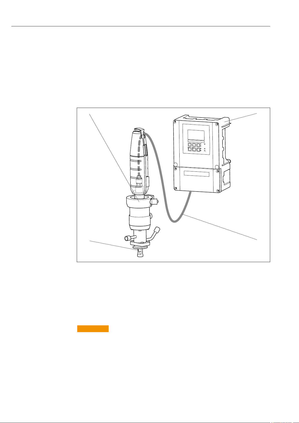
5.2.1 Measuring system
A complete measuring system comprises:
• An Oxymax COS22 oxygen sensor
• A transmitter, e.g. Liquisys COM2x3
• Measuring cable COK21
• Optional: an assembly, e.g. permanent installation assembly CPA442, flow assembly
CPA240, or retractable assembly CPA875
3 Example of a measuring system with COS22-*1
1 Retractable assembly CPA875
2 Transmitter Liquisys COM253
3 Measuring cable COK21
4 Oxygen sensor COS22
5.2.2 Installing a measuring point
Installation in suitable assembly is required (depending on the application)
WARNING
L
Electrical voltage
In the event of a fault, non-grounded metallic assemblies may be under voltage and then
are not touchable.
When using metallic assemblies and installation equipment, observe the national
‣
grounding provisions.
10 Endress+Hauser
A0024029

Oxymax COS22 Installation
For a complete installation of a measuring point, proceed as follows:
1. Install a retractable or a flow assembly (if used) into the process.
2. Connect the water supply to the rinse connections (if you use an assembly with
cleaning function).
3. Install and connect the oxygen sensor.
NOTICE
Installation error
Cable open circuit, loss of sensor due to cable separation, unscrewing of membrane cap
Do not install the sensor suspended from the cable.
‣
Screw the sensor into the assembly so that the cable is not twisted.
‣
When installing or uninstalling the sensor body, hold it tightly. Turn using only the
‣
hexagonal nut on the armored coupling. Otherwise you might unscrew the membrane
cap. This will then remain in the assembly or process.
Avoid exerting excessive tensile force on the cable (e.g. from jerky pulling).
‣
Select an installation location that is easy to access for later calibrations.
‣
5.3 Installation examples
5.3.1 Permanent installation (CPA442)
The permanent installation assembly CPA442 enables easy adaptation of a sensor to
nearly any process connections from Ingold nozzles to Varivent or Tri-Clamp connections.
This kind of installation is very well suited for tanks and larger pipes. You will achieve a
defined immersion depth of the sensor into the medium in the simplest way.
5.3.2 Flow assembly
CPA240
The flow assembly CPA240 offers up to three installation spaces for sensors with a shaft
diameter of 12 mm (0.47"), a shaft length of 120 mm (4.7"), and a Pg 13.5 process
connection. It very well suited for use in pipelines or hose connections. To prevent
Endress+Hauser 11
 Loading...