

Page 1
BA01349C/07/EN/03.18
71430357
2018-10-31
Products Solutions Services
Operating Instructions
OUSAF46
Optical sensor with the OUA260 flow assembly for
the measurement of UV absorption
Page 2

Table of contents OUSAF46
Table of contents
1 About this document ........... 3
1.1 Warnings ........................... 3
1.2 Symbols ............................ 3
1.3 Symbols on the product ............... 4
2 Basic safety instructions ....... 4
2.1 Requirements for the personnel ........ 4
2.2 Designated use ...................... 4
2.3 Occupational safety .................. 4
2.4 Operational safety ................... 5
2.5 Product safety ....................... 5
3 Product description ............. 6
3.1 Measuring principle .................. 6
9 Repair .......................... 30
9.1 Return ............................ 30
9.2 Disposal ........................... 30
10 Accessories .................... 30
10.1 Flow assembly ...................... 31
10.2 Cable ............................. 31
10.3 Calibration ......................... 31
11 Technical data ................. 31
11.1 Input .............................. 31
11.2 Environment ....................... 32
11.3 Process ............................ 32
11.4 Mechanical construction ............. 32
4 Incoming acceptance and
product identification .......... 7
4.1 Incoming acceptance ................. 7
4.2 Product identification ................. 7
4.3 Manufacturer's address ............... 8
4.4 Scope of delivery ..................... 8
4.5 Certificates and approvals ............. 8
5 Installation ...................... 9
5.1 Installation conditions ................ 9
5.2 Mounting the sensor ................ 11
5.3 Post-installation check ............... 12
6 Electrical connection .......... 12
6.1 Connecting the sensor ............... 13
6.2 Lamp voltage ....................... 14
6.3 Ensuring the degree of protection ..... 14
6.4 Post-connection check ............... 15
7 Commissioning ................ 16
7.1 Function check ..................... 16
7.2 Calibrating/adjusting the sensor ...... 16
8 Maintenance .................. 18
8.1 Maintenance schedule ............... 19
8.2 Replacing the hazardous area lamp .... 19
8.3 Replacing the mercury lamp .......... 19
8.4 Replacing the reference filter ......... 22
8.5 Replacing the measurement filter ..... 24
8.6 Replacing the sensor window and
seal ............................... 28
Index ................................. 34
2 Endress+Hauser
Page 3
OUSAF46 About this document
1 About this document
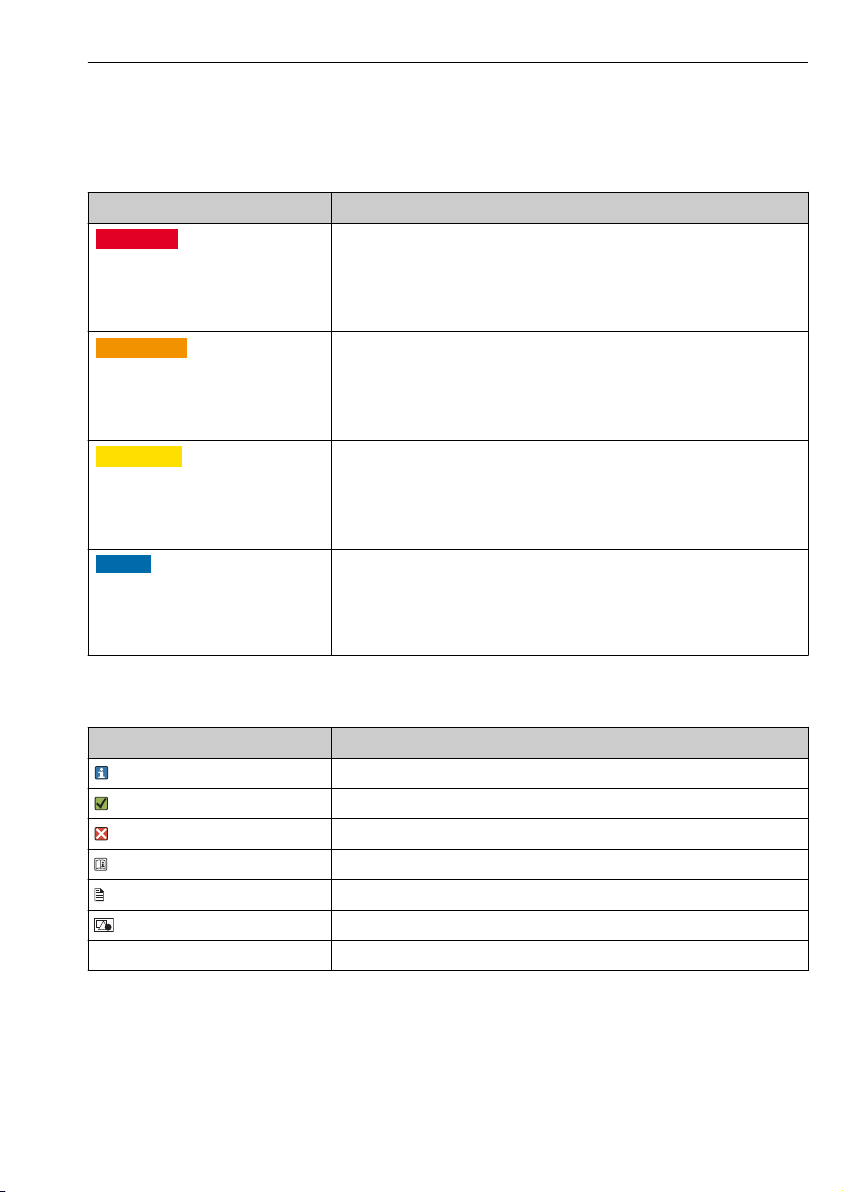
1.1 Warnings
Structure of information Meaning
DANGER
L
Causes (/consequences)
If necessary, Consequences of noncompliance (if applicable)
Corrective action
‣
WARNING
L
Causes (/consequences)
If necessary, Consequences of noncompliance (if applicable)
Corrective action
‣
CAUTION
L
Causes (/consequences)
If necessary, Consequences of noncompliance (if applicable)
Corrective action
‣
NOTICE
Cause/situation
If necessary, Consequences of noncompliance (if applicable)
Action/note
‣
This symbol alerts you to a dangerous situation.
Failure to avoid the dangerous situation will result in a fatal or serious injury.
This symbol alerts you to a dangerous situation.
Failure to avoid the dangerous situation can result in a fatal or serious injury.
This symbol alerts you to a dangerous situation.
Failure to avoid this situation can result in minor or more serious injuries.
This symbol alerts you to situations which may result in damage to property.
1.2 Symbols
Symbol Meaning
Additional information, tips
Permitted or recommended
Not permitted or not recommended
Reference to device documentation
Reference to page
Reference to graphic
Result of a step
Endress+Hauser 3
Page 4
Basic safety instructions OUSAF46
1.3 Symbols on the product
Symbol Meaning
Reference to device documentation
2 Basic safety instructions
2.1 Requirements for the personnel
• Installation, commissioning, operation and maintenance of the measuring system may be
carried out only by specially trained technical personnel.
• The technical personnel must be authorized by the plant operator to carry out the specified
activities.
• The electrical connection may be performed only by an electrical technician.
• The technical personnel must have read and understood these Operating Instructions and
must follow the instructions contained therein.
• Faults at the measuring point may only be rectified by authorized and specially trained
personnel.
Repairs not described in the Operating Instructions provided must be carried out only
directly at the manufacturer's site or by the service organization.
2.2 Designated use
The sensor measures the spectral absorption of process liquids in the ultraviolet region of the
electromagnetic spectrum. The sensor is suitable for use in a wide range of applicationsin a
variety of industrial sectors , such as:
• Measurement of protein concentrations
• Chromatography monitoring
• Filtration monitoring
• Concentration measurement of organic compounds
• Detection of aromates
Use of the device for any purpose other than that described, poses a threat to the safety of
people and of the entire measuring system and is therefore not permitted.
The manufacturer is not liable for damage caused by improper or non-designated use.
2.3 Occupational safety
As the user, you are responsible for complying with the following safety conditions:
• Installation guidelines
• Local standards and regulations
• Regulations for explosion protection
4 Endress+Hauser
Page 5
OUSAF46 Basic safety instructions
Electromagnetic compatibility
• The product has been tested for electromagnetic compatibility in accordance with the
applicable European standards for industrial applications.
• The electromagnetic compatibility indicated applies only to a product that has been
connected in accordance with these Operating Instructions.
2.4 Operational safety
Before commissioning the entire measuring point:
1. Verify that all connections are correct.
2. Ensure that electrical cables and hose connections are undamaged.
3. Do not operate damaged products, and protect them against unintentional operation.
4. Label damaged products as defective.
During operation:
If faults cannot be rectified:
‣
products must be taken out of service and protected against unintentional operation.
2.5 Product safety
2.5.1 State of the art
The product is designed to meet state-of-the-art safety requirements, has been tested, and
left the factory in a condition in which it is safe to operate. The relevant regulations and
European standards have been observed.
2.5.2 Versions with hazardous area lamp
Also observe the safety instructions in the XA for these Operating Instructions.
Safety instructions for electrical apparatus in hazardous areas, photometer sensors,
XA01403C/07/A3
Endress+Hauser 5
Page 6

Product description OUSAF46
1
OPL
2
3
4
5
68
7 2
3 Product description
3.1 Measuring principle
Light absorption
The measuring principle is based on the Lambert-Beer law.
There is a linear dependency between the absorption of light and the concentration of the
absorbing substance:
A = -log(T) = ε . c . OPL
T = I/I
0
T ... Transmission
I ... Intensity of received light at detector
I0 ... Intensity of transmitted light of light source
A ... Absorption
ε ... Extinction coefficient
c ... Concentration
OPL ... Optical path length
A light source emits radiation through the medium and the incident radiation is measured on
the detector side.
The subsequent conversion to absorbance units (AU, OD) is performed in the associated
transmitter.
1 Absorption measurement with reference
1 Light source
2 Optical windows
3 Measurement filter
4 Measuring detector
5 Lens
6 Medium flow
7 Reference filter
8 Reference detector
OUSAF46 has 2 pairs of reference and measuring detectors (= 2 channels). Only one
channel is shown for the sake of simplicity.
6 Endress+Hauser
A0029412
Page 7

OUSAF46 Incoming acceptance and product identification
4 Incoming acceptance and product identification
4.1 Incoming acceptance
1. Verify that the packaging is undamaged.
Notify the supplier of any damage to the packaging.
Keep the damaged packaging until the issue has been resolved.
2. Verify that the contents are undamaged.
Notify the supplier of any damage to the delivery contents.
Keep the damaged goods until the issue has been resolved.
3. Check that the delivery is complete and nothing is missing.
Compare the shipping documents with your order.
4. Pack the product for storage and transportation in such a way that it is protected
against impact and moisture.
The original packaging offers the best protection.
Make sure to comply with the permitted ambient conditions.
If you have any questions, please contact your supplier or your local Sales Center.
4.2 Product identification
4.2.1 Nameplate
The nameplate provides you with the following information on your device:
• Manufacturer identification
• Order code
• Serial number
• Safety information and warnings
Compare the information on the nameplate with the order.
‣
4.2.2 Product identification
Product page
www.endress.com/ousaf46
Interpreting the order code
The order code and serial number of your product can be found in the following locations:
• On the nameplate
• In the delivery papers
Obtaining information on the product
1. Go to www.endress.com.
2. Call up the site search (magnifying glass).
3. Enter a valid serial number.
Endress+Hauser 7
Page 8

Incoming acceptance and product identification OUSAF46
4. Search.
The product structure is displayed in a popup window.
5. Click on the product image in the popup window.
A new window (Device Viewer) opens. All of the information relating to your
device is displayed in this window as well as the product documentation.
4.3 Manufacturer's address
Endress+Hauser Conducta Inc.
4123 East La Palma Avenue, Suite 200
Anaheim, CA 92807 USA
4.4 Scope of delivery
The scope of delivery consists of the following :
• Detector and lamp module without flow assembly or
• Detector and lamp module mounted on flow assembly
• Operating Instructions
Ordering the sensor together with a transmitter:
If you select the calibration option in the Product Configurator for the transmitter, the
complete measuring system (transmitter, sensor, cable) is factory-calibrated and shipped
as one package.
If you have any queries:
‣
Please contact your supplier or local sales center.
4.5 Certificates and approvals
4.5.1 mark
Declaration of Conformity
The product meets the requirements of the harmonized European standards. As such, it
complies with the legal specifications of the EU directives. The manufacturer confirms
successful testing of the product by affixing to it the mark.
4.5.2 Hazardous area approvals
• ATEX II 2G Ex db IIC T5 Gb
• FM Cl.1, Div. 1, Groups B, C, D
4.5.3 FDA conformity
All non-metal parts in contact with medium, such as rubber and plastic parts, meet the
requirements of FDA 21 CFR 177.2600. The plastic and elastomer parts of the sensor in
contact with medium have passed the biological reactivity tests according to USP <87> and
<88> Class VI.
8 Endress+Hauser
Page 9
OUSAF46 Installation
1 2
3
7
5
4
6
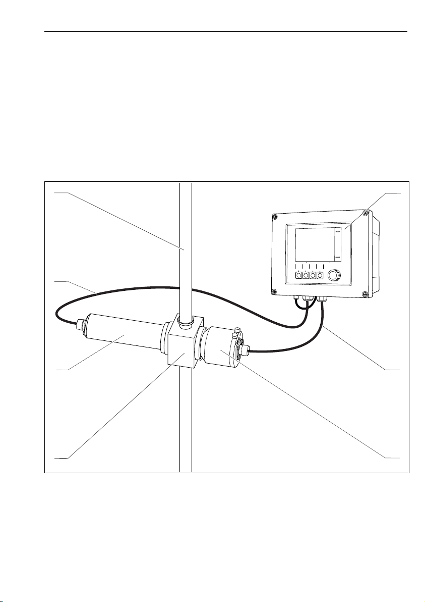
5 Installation
5.1 Installation conditions
5.1.1 Measuring system
An optical measuring system comprises:
• Sensor (photometer) OUSAF46
• Transmitter, e. g. Liquiline CM44P
• Cable set, e. g. CUK80
• Assembly OUA260
2 Example of a measuring system with a photometer sensor
1 pipe 5 Flow assembly OUA260
2 Transmitter CM44P 6 Sensor: light source (lamp)
3 CUK80 cable set 7 CUK80 cable set
4 Sensor: detector
Endress+Hauser 9
Page 10

Installation OUSAF46
A B
C
5.1.2 Dimensions
A0035258
3 Sensor module
A Dimension of lamp → Table
B Dimension of detector → Table
C Assembly, see Technical Information for assembly
Lamp type Dimension A in mm (inch)
Standard lamp 146.1 (5.75)
Detector type Dimension B in mm (inch)
Standard version with test filter 80 (3.15)
Easycal 94 (3.70)
The total length of the sensor module is derived from the lengths of the lamp, the
detector and the assembly.
The dimensions of the OUA260 assembly are provided in Technical Information,
TI00418C.
Allow an additional gap of 5 cm (2") on both the lamp side and detector side of the sensor
‣
to connect the sensor cable.
10 Endress+Hauser
Page 11
OUSAF46 Installation
A
B
C
D
E
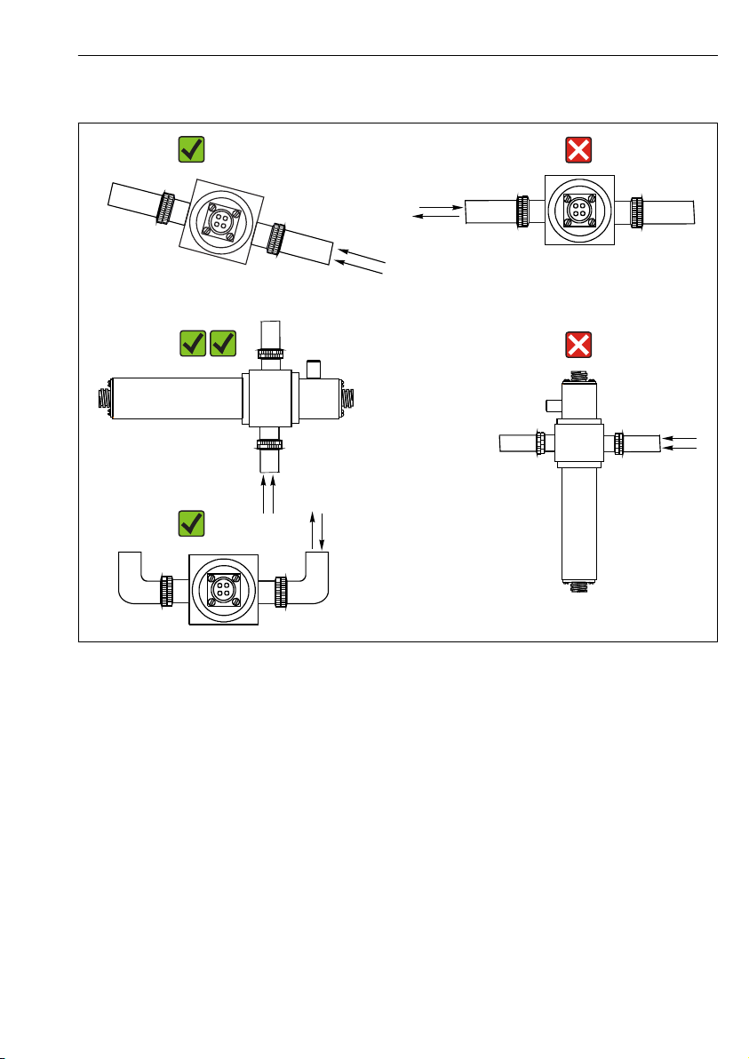
5.1.3 Mounting angles
4 Mounting angles. The arrows indicate the direction of medium flow in the pipe.
A Suitable mounting angle, better than C
B Optimum mounting angle, best installation position
C Acceptable mounting angle
D Mounting angle to be avoided
E Forbidden mounting angle
5.2 Mounting the sensor
The sensors have been specifically designed so that they can be installed in the process
together with a flow assembly, such as the OUA260. The flow assembly can be installed either
directly in a process line or in a bypass line.
The sensor cannot be used without an assembly.
Make sure that the sensor housing and detector housing are aligned horizontally. This
‣
ensures that the optical windows are vertically aligned as this prevents buildup on the
window surfaces.
Endress+Hauser 11
A0028250
Page 12

Electrical connection OUSAF46
Install the sensor upstream from the pressure regulators.
‣
Leave enough room for the cable connector at the end of the lamp and at the end of the
‣
detector housing. Unimpeded access to these areas is also required for connection/removal
tasks.
The operation of sensors under pressure prevents the formation of air or gas bubbles.
‣
NOTICE
Mounting errors
Possibility of sensor damage, twisted cables or similar
Make sure that the sensor bodies are protected against damage from external forces - such
‣
as trolleys on adjacent paths.
Remove the cable before you screw the lamp or detector onto the flow assembly.
‣
Make sure to avoid exerting excessive tensile force on the cable (e.g. from jerky pulling
‣
movements).
Make sure to observe the national grounding regulations when using metal assemblies.
‣
If the sensor is ordered together with the assembly OUA260, the flow assembly is readymounted on the sensor upon delivery. The sensor is ready for use immediately.
If the sensor and assembly are ordered separately, you must mount the sensor as follows:
1. Install flow assembly OUA260 in the process via the process connections.
2. Make sure to fit the O-ring seals on the lamp and detector.
Screw the lamp and detector onto the flow assembly.
The lamp and detector can be installed in and removed from the assembly without this
affecting the process line.
5.3 Post-installation check
Put the sensor into operation only if you can answer "yes" to the following questions:
• Are the sensor and cable undamaged?
• Have you chosen a correct mounting angle?
6 Electrical connection
WARNING
L
Device is live!
Incorrect connection may result in injury or death!
The electrical connection may be performed only by an electrical technician.
‣
The electrical technician must have read and understood these Operating Instructions and
‣
must follow the instructions contained therein.
Prior to commencing connection work, ensure that no voltage is present on any cable.
‣
12 Endress+Hauser
Page 13

OUSAF46 Electrical connection
BK
GY
RD
A
B
YE
YE
BK
BK
GY
RD
BK
B
GY
WH
GN
GN
GY
WH
6.1 Connecting the sensor
The sensor is connected to the transmitter using the pre-terminated or labeled cable set
CUK80 (for connection to CM44P) or OUK (for connection to CVM40) . The terminals and
labeling may vary depending on the transmitter in use. The cable set must be ordered
separately.
A0033423
5 OUSAF46 connecting cable
A Light source (lamp) power supply
B Signals of measurement and reference detector
CM44P terminal CVM40 terminal Cable color Assignment
PEM module 1
P+ V1.1 YE (thick) Lamp voltage +
S+ V1.3 YE (thin) Detection of lamp voltage +
S- V1.4 BK (thin) Detection of lamp voltage -
P- V1.2 BK (thick) Lamp voltage -
A (1) S1.1 RD Channel 1 Sensor measuring detector +
C(1) S1.2 BK Channel 1 Sensor measuring detector -
Endress+Hauser 13
Page 14

Electrical connection OUSAF46
CM44P terminal CVM40 terminal Cable color Assignment
SH (1) S1.S GY Channel 1 Shield
A (2) S2.1 WH (lamp) Channel 1 Sensor reference +
C(2) S2.2 GN (lamp) Channel 1 Sensor reference -
SH (2) S2.S GY (lamp) Channel 1 Shield
PEM module 2
A (1) S3.1 WH Channel 2 Sensor measuring detector +
C(1) S3.2 GN Channel 2 Sensor measuring detector -
SH (1) S3.S GY Channel 2 Shield
A (2) S4.1 RD (lamp) Channel 2 Sensor reference +
C(2) S4.2 BK (lamp) Channel 2 Sensor reference -
SH (2) S4.S GY (lamp) Channel 2 Shield
6.2 Lamp voltage
Sensor version Lamp type Lamp voltage [V]
OUSAF46-xxxx Low-pressure mercury lamp 10.0 ± 0.1
6.3 Ensuring the degree of protection
Only the mechanical and electrical connections which are described in these instructions and
which are necessary for the required, designated use, may be carried out on the device
delivered.
Exercise care when carrying out the work.
‣
Individual types of protection permitted for this product (impermeability (IP), electrical safety,
EMC interference immunity, Ex protection) can no longer be guaranteed if, for example :
• Covers are left off
• Different power units to the ones supplied are used
• Cable glands are not sufficiently tightened (must be tightened with 2 Nm (1.5 lbf ft) for the
permitted level of IP protection)
• Unsuitable cable diameters are used for the cable glands
• Modules are not fully secured
• The display is not fully secured (risk of moisture entering due to inadequate sealing)
• Loose or insufficiently tightened cables/cable ends
• Conductive cable strands are left in the device
14 Endress+Hauser
Page 15

OUSAF46 Electrical connection
6.4 Post-connection check
Device condition and specifications Notes
Are the sensor, assembly and cable free from damage on the outside? Visual inspection
Electrical connection Notes
Does the supply voltage of the connected transmitter match the data on the
nameplate?
Are the installed cables strain-relieved and not twisted?
Has the cable been routed without loops and cross-overs? Check that it is firmly seated (by
Are the signal cables connected correctly according to the connection diagram?
Are all cable entries mounted, tightened and leak-tight? For lateral cable entries, make sure
Are the PE distributor rails grounded (if present)? Grounding at the point of
Visual inspection
pulling gently)
the cables loop downwards to allow
water to drip off.
installation
Endress+Hauser 15
Page 16

Commissioning OUSAF46
7 Commissioning
7.1 Function check
Prior to initial commissioning, ensure that:
• The sensor is correctly installed
• The electrical connection is correct.
7.2 Calibrating/adjusting the sensor
Measuring points consisting of a photometer sensor, flow assembly (if provided) and a
transmitter are adjusted at the factory. Normally adjustment is not required when
commissioning for the first time.
If an adjustment is desired nevertheless, you have the following adjustment options:
• Adjustment with calibration standards
• Use of Easycal
7.2.1 Calibration/adjustment with standard solutions
Use solutions with a known absorbance (at the sensor wavelength) for the calibration/
adjustment.
WARNING
L
Potassium dichromate is toxic, flammable, carcinogenic and has mutagenic effects!
Can cause cancer, genetic defectives, affect fertility, harm the unborn child and intensify fires.
Potentially life-threatening if inhaled, toxic if swallowed, harmful if it comes into contact with
skin. Causes severe skin burns and severe eye damage!
When working with potassium dichromate, always wear protective gloves and protective
‣
goggles.
Seek special advice before use.
‣
Follow all of the instructions on the manufacturer's safety data sheet.
‣
Use calibration solutions that are suitable for the measuring task. Examples of solutions which
are commonly used include:
Potassium dichromate, K2Cr2O
A solution of 182 ml 0.1N K2Cr2O7, diluted to one liter, has an absorbance of approx. 10 OD at
280 nm. By diluting the solution, you can produce a series of calibration solutions which you
can use to adjust the measuring point.
AU = OD*OPL[cm]
AU ... absorbance units, OD ... optical density, OPL .... optical path length
Instead of potassium dichromate you can also use your process medium for calibrating/
adjusting and for application calibration. Here, also produce a series of dilutions of
known concentration and determine the absorbance in the laboratory.
16 Endress+Hauser
7
Page 17

OUSAF46 Commissioning
1 2
34
7.2.2 Easycal
Easycal enables you to perform a calibration/an adjustment which is traceable to NIST
without any liquid standards.
Detector with Easycal: function
6 Filter in "out" position
1 NIST-traceable filter (high)
2 Locking screw
Every Easycal device has two traceable filters - one filter with a nominal 0.5 AU and another
filter with 1 AU (absorbance unit) - which are placed individually or together in the device
measuring path. These filter(s) are scanned with traceable testing equipment and the actual
absorbance at individual wavelengths is determined.
It is very important that you use the actual values of the optical Easycal filter. These values are
given in the calibration certificate supplied.
Enter the absorbance values (CM44P): Menu/Setup/Inputs/Photometer/Extended
‣
setup/Measurement channel/Calib. settings/EasyCal = Yes, NIST filter high and NIST
filter low.
Send Easycal in to your Service Center once a year for recertification. This comprises
complete functional testing and the recertification of the filters in accordance with
sources that are traceable to NIST.
7.2.3 Visual inspection
A reference rod is included in the delivery for every standard sensor (sensor without Easycal).
In this way, it is possible to perform a functional test on the device without having to use
calibration solutions.
A0033709
7 Filter in "in" position
3 Positioning pin
4 Lens assembly
A0033708
Endress+Hauser 17
Page 18

Maintenance OUSAF46
The reference rod is screwed into the sensor detector housing, thereby partially blocking the
sensor light. This simulates the absorbance in the optical chain.
The cross-sectional view of the measuring detector below illustrates the position of the
reference rod and its blocking effect.
A0035261
8 Cross-section of detector module with reference rod inserted
Proceed as follows to obtain a value for the reference rod during commissioning:
1. Fill the flow assembly with water. Make sure that the measured value "zero" is displayed.
2. Insert the reference rod into the detector housing.
Make a note of the measured value.
You can check the calibration any time later on by filling the flow assembly with water again
and re-inserting the reference rod. The measured value should be equal to the value noted
down.
8 Maintenance
Take all the necessary precautions in time to ensure the operational safety and reliability of
the entire measuring system.
NOTICE
Effects on process and process control!
When carrying out any work on the system, bear in mind any potential impact this could
‣
have on the process control system and the process itself.
For your own safety, only use genuine accessories. With genuine parts, the function,
‣
accuracy and reliability are also ensured after maintenance work.
18 Endress+Hauser
Page 19

OUSAF46 Maintenance
NOTICE
Sensitive optical components
If you do not proceed with care, you can damage or severely dirty the optical components.
Maintenance work may only be carried out by appropriately qualified staff.
‣
Use ethanol and a lint-free cloth which is suitable for cleaning lenses to clean all the
‣
optical components.
8.1 Maintenance schedule
• Maintenance and servicing intervals are based on the individual application.
• Cleaning intervals depend on the medium.
Maintenance checklist
• Replace lamp
The lamp is typically replaced after 1000 to 3000 operating hours (→ 33).
• Replace sensor window and seal
The window only needs to be replaced if it is damaged.
• Replace O-rings in contact with the medium
The replacement of O-rings in contact with the medium depends on the specific
requirements of the process.
Never re-use a used O-ring.
8.2 Replacing the hazardous area lamp
The disassembly and assembly process for the hazardous area lamp is the same as for the
non-hazardous area version.
Make sure you use the right spare parts kit.
8.3 Replacing the mercury lamp
WARNING
L
Dangerous voltage
Risk of serious or fatal injury from electric shock!
Before performing any maintenance work on the lamp, remove all the cables and
‣
disconnect the power supply to the sensor.
Only replace the lamp in a current-free state.
‣
CAUTION
L
Mercury lamp
UV radiation can damage the eyes!
Protect your eyes with protective goggles suitable for UV radiation.
‣
Never look directly into a mercury lamp when it is switched on.
‣
Endress+Hauser 19
Page 20

Maintenance OUSAF46
Removing the used lamp
Switch off the lamp using the software function on the transmitter.
‣
Remove the lamp cable.
‣
Allow the lamp to cool down (30 minutes).
‣
1.
Turn the lamp module counterclockwise to remove it from the flow assembly.
2.
Use a 1" open-ended wrench. With the wrench, hold the base plate of the cable
connector in position and unscrew the lamp housing in a counterclockwise direction by
hand.
Remove the lamp and reflector unit from the housing.
3.
Loosen the securing screw holding the lamp by 1-2 rotations.
20 Endress+Hauser
Page 21

OUSAF46 Maintenance
4.
Hold the lamp socket in the gap between the lamp power supply unit and the reflector
and press it out of its fitting. Do not damage the cable of the circuit board! Then press
the lamp out completely through the reflector.
Dispose of the used lamp in accordance with local regulations for lamps containing
mercury.
5. Check whether the cables of the lamp module are worn, or whether the reflector is
damaged.
Inserting a new lamp
When working with the lamp, use a cloth for lenses or wear talc-free latex gloves.
1.
Clean the new lamp and the reflector with ethanol and a cloth for cleaning the lens.
Do not touch optical surfaces once they have been cleaned!
2.
Guide the new lamp carefully through the reflector and into the socket.
Make sure that the lamp is securely seated in the correct position.
Endress+Hauser 21
Page 22

Maintenance OUSAF46
3.
Retighten the securing screw.
This screw is only used to hold the lamp in position. Therefore, do not tighten it too
tightly as to do so could damage or break the lamp.
4. Make sure that the lamp contact area is completely clean and dry before re-closing.
5.
Screw the lamp and reflector group back into its housing and tighten it by hand.
6.
Mount the complete lamp module back into the flow assembly.
After replacing the lamp, the system needs to be adjusted. In addition, you must reset the
operating hours counter for the lamp on the CM44P: CAL/Photometer/Lamp operating
time/Reset.
8.4 Replacing the reference filter
WARNING
L
Dangerous voltage
Risk of serious or fatal injury from electric shock!
Before performing any maintenance work on the lamp, remove all the cables and
‣
disconnect the power supply to the sensor.
Only replace the filter in a current-free state.
‣
22 Endress+Hauser
Page 23

OUSAF46 Maintenance
1
2
3
4
CAUTION
L
Mercury lamp
UV radiation can damage the eyes!
Protect your eyes with protective goggles suitable for UV radiation.
‣
Never look directly into a mercury lamp when it is switched on.
‣
Switch off the lamp using the software function on the transmitter.
‣
Remove the lamp cable.
‣
Allow the lamp to cool down (30 minutes).
‣
Remove the lamp module from the flow assembly, disassemble the lamp housing and
‣
remove the lamp and reflector unit from the housing. Proceed in the exact same way as
described for replacing the mercury lamp.→ 20
9 Replacing the reference filter
1 Screw on circuit board
2 O-ring
3 Reference filter
4 Lamp holder
1. Remove both screws (item 1), and release the circuit board from the lamp holder (item
4).
2. Turn over the lamp holder and allow the filter (item 3) to fall into your hand.
3. Insert the new filter. In doing so, make sure that the "reflective" side is facing towards
the light source. Use the correct filter (reference filter) from the spare parts kit!
4. Fit the circuit board back on and tighten the screws slightly.
5. Reassemble the lamp module and mount it back on the assembly.
You must then recalibrate/readjust the measuring system.
Endress+Hauser 23
Page 24

Maintenance OUSAF46
In addition, you must reset the counter for filter replacement in the case of the CM44P: CAL/
Photometer/Filter change/Reset
8.5 Replacing the measurement filter
Versions with Easycal:
If the Easycal detector module is sent in for recertification, a diagnostic scan of the
measurement filter is performed and the measurement filter is replaced if necessary.
Do not replace the filter yourself.
Versions with a standard detector
Please note that the measurement filters are not identical. Their arrangement in the
measuring channels must correspond to the arrangement of the reference filters in the lamp.
Measuring channel 1 is always reserved for the filter with the wavelength 280 nm.
The wavelength is indicated on the socket of the filters. In addition, the measuring channels
are marked on the bottom of the detector module on leaving the factory.
To avoid any confusion, replace the filters one after the other.
1.
Release sensor cable from detector and unscrew detector from flow assembly.
2.
Release the four screws holding the detector housing.
24 Endress+Hauser
Page 25

OUSAF46 Maintenance
3.
Remove housing along with lens assembly.
4.
Release two anodized (black) screws.
5.
Carefully pull apart. Do not damage or break wires!
6.
Release screws on board.
Endress+Hauser 25
Page 26

Maintenance OUSAF46
7.
Remove board.
8.
Loosen securing screw.
9.
Press out filter.
The wavelength of the filter is indicated on the socket.
10.
Use filters that have the same wavelength.
The arrow on the socket indicates the installation direction.
26 Endress+Hauser
Page 27

OUSAF46 Maintenance
11.
Tighten securing screw for filter.
12. 2. Replace the measurement filter in the same way (release screw, press out filter, insert
new filter, tighten screw).
13.
Re-install board. Pay attention to wires.
14.
Re-secure the filter holder using the two anodized screws.
15.
Insert the entire assembly into the detector housing and screw down.
Endress+Hauser 27
Page 28

Maintenance OUSAF46
16.
Re-attach the detector to the flow assembly, screw on sensor cable.
Then recalibrate/readjust the measuring system.
In addition, reset the counter for filter replacement in the case of the CM44P: CAL/
Photometer/Filter change/Reset
8.6 Replacing the sensor window and seal
Operating Instructions for Flowcell OUA260, BA01600C
Operating Instructions for CUA261, BA01652C
If you have mounted the sensor in a VARIVENT flow assembly using the CUA261
adapter, refer to the Operating Instructions of the adapter for information on removal
and on replacing the optical windows.
Removing optical windows and seals
Always replace windows with windows of the same type in order to maintain the path length.
The following applies for OUA260:
The flow assembly must be removed from the process line in order to replace the windows
and seals.
1. In the case of OUA260 only:
Stop the flow in the process pipe and remove the assembly from the dry process line.
2. Remove the lamp and detector housing from the assembly.
28 Endress+Hauser
Page 29

OUSAF46 Maintenance
The following description applies for both sides, i.e. the detector side and the lamp side.
Always change O-rings or optical windows
1)
on both sides.
3.
Remove the 4 Allen screws (1/8" or 3 mm) from the window ring. Make sure to loosen
the screws evenly and alternately around the window ring.
4.
Remove the window ring .
5.
Gently push the optical window out of the assembly. If the window jams, apply some
acetone around the window seal (O-ring) and wait a few minutes for it to take effect.
This should help release the window. The seal cannot be reused afterwards!
Checking or replacing optical windows and seals
1. Check the window area for residue or fouling. Clean if necessary.
2. Check the optical windows for signs of chipping or abrasion.
Replace the windows if signs of chipping/abrasion are found.
3. Dispose of all the O-rings and replace them with new O-rings from the relevant
maintenance kit.
1) Optical windows only need to be replaced if they are damaged.
Endress+Hauser 29
Page 30

Repair OUSAF46
4. Mount the optical window and then the window ring, along with the new seals, on the
assembly. Make sure to tighten the screws of the window ring uniformly in a diagonally
opposite sequence. In this way, you ensure that the ring is seated correctly.
5. If the optical windows and the window rings are not identical, make sure the lamp is on
the right side. The lamp should be on the side with the "shorter" window length.
Then mount the lamp and detector on the assembly.
If you have changed the path length by installing other optical windows, you then have
to configure the measuring system appropriately.
In any case, you must always perform an adjustment with liquids after disassembling and
assembling the windows.
9 Repair
9.1 Return
The product must be returned if repairs or a factory calibration are required, or if the wrong
product was ordered or delivered. As an ISO-certified company and also due to legal
regulations, Endress+Hauser is obliged to follow certain procedures when handling any
returned products that have been in contact with medium.
To ensure the swift, safe and professional return of the device:
Refer to the website www.endress.com/support/return-material for information on the
‣
procedure and conditions for returning devices.
9.2 Disposal
The device contains electronic components. The product must be disposed of as electronic
waste.
Observe the local regulations.
‣
10 Accessories
The following are the most important accessories available at the time this documentation
was issued.
For accessories not listed here, please contact your Service or Sales Center.
‣
30 Endress+Hauser
Page 31

OUSAF46 Technical data
10.1 Flow assembly
OUA260
• Flow assembly for hygienic sensors
• For sensor installation in pipes
• Materials: stainless steel 316, 316L or Kynar (other materials available on request)
• Wide variety of process connections and path lengths available
• Product Configurator on the product page: www.endress.com/oua260
Technical Information TI00418C
10.2 Cable
CUK80 cable set
• Pre-terminated and labeled cables for connecting analog photometer sensors
• Product Configurator on the product page: www.endress.com/cuk80
10.3 Calibration
Kit OUSAF46 EasyCal retrofit kit
• Patented system traceable to NIST for the calibration of UV absorption sensors
• Order numbers:
– 254 nm: 71210149
– 280 nm: 71210150
– 295 nm: 71210156
– 313 nm: 71210151
Reference rod
Order number: 71108543
11 Technical data
11.1 Input
11.1.1 Measured variable
UV-absorption
11.1.2 Measuring range
• 0 to 2.5 AU
• Max. 50 OD (depending on the optical path length)
11.1.3 Wavelength
Discrete wavelength at 254, 280, 295 or 313 nm
Endress+Hauser 31
Page 32

Technical data OUSAF46
11.2 Environment
11.2.1 Ambient temperature range Non-hazardous area versions
0 to 55 °C (32 to 131 °F)
Hazardous area versions
2 to 40 °C (36 to 104 °F)
11.2.2 Storage temperature
-10 to +70 °C (+10 to +160 °F)
11.2.3 Humidity
5 to 95 %
11.2.4 Degree of protection
IP66 and NEMA 4X
11.3 Process
11.3.1 Process temperature
0 to 90 °C (32 to 194 °F) continuous
Max. 130 °C (266 °F) for 2 hours
11.3.2 Process pressure
Max. 100 bar (1450 psi) absolute, depending on the material, pipe size and process
connection of the flow assembly
11.4 Mechanical construction
11.4.1 Dimensions
→ 10
11.4.2 Weight
Sensor
UV lamp 0.58 kg (1.28 lbs)
UV lamp with wire-braided cable
(1.2 m (4 ft)) and junction box (sensor
for hazardous area)
Easycal detector 0.53 kg (1.17 lbs)
Standard detector 0.78 kg (1.71 lbs)
32 Endress+Hauser
3.2 kg (6.66 lbs)
Page 33

OUSAF46 Technical data
11.4.3 Materials
Sensor housing Stainless steel 316
Assembly OUA260 Stainless steel 316, 316L or Kynar
Cable connector ends Nickel-plated brass
11.4.4 Light source
Low-pressure mercury lamp
Lamp operating life: typically 3000 h
The lamp will not operate at full capacity until a warm-up period of 30 minutes has
elapsed.
11.4.5 Detector
UV silicon detector, hermetically sealed
11.4.6 Filter
Multilayer interference filter, designed for extreme UV conditions
Endress+Hauser 33
Page 34

Index OUSAF46
Index
A
Accessories ..................... 30
C
Check
Connection .................. 15
Installation .................. 12
Connection
Check ..................... 15
Measuring device ...............13
D
Declaration of Conformity ............. 8
Designated use ....................4
Device description .................. 6
Dimensions ..................... 10
Disposal ....................... 30
E
Easycal ........................17
Ensuring the degree of protection ........ 14
F
Function check ................... 16
I
Incoming acceptance ................ 7
Installation
Check ..................... 12
Installation conditions ............... 9
L
Lamp voltage .................... 14
O
Occupational safety ................. 4
Operational safety ..................5
P
Power supply
Connecting the measuring device ..... 13
Product identification ................ 7
Product safety .................... 5
R
Reference rod ....................17
Replacing
Mercury lamp .................19
Sensor window and seal ...........28
Requirements for the personnel .......... 4
Return ........................ 30
S
Safety
Occupational safety .............. 4
Operation ....................5
Product ..................... 5
Safety instructions ..................4
Scope of delivery ...................8
Symbols ...................... 3, 4
T
Technical personnel ................. 4
U
Use
Designated ................... 4
M
Maintenance schedule ...............19
Measured variable ................. 31
Measuring principle .................6
Measuring range ..................31
Measuring system .................. 9
Mounting angles ..................11
Mounting the sensor ................11
W
Warnings ....................... 3
Wavelength .....................31
N
Nameplate ...................... 7
34 Endress+Hauser
Page 35

Page 36

*71430357*
71430357
www.addresses.endress.com
 Loading...