

Page 1

Technical Information
omnigrad T TR25
Thermometer without extension neck
Threaded connection under the head
®
PCP (4...20 mA), HART
or PROFIBUS-PA® electronics
Temperature sensors TR 25, series
thermometers suitable for almost all industrial processes and
generic applications thanks
They are made up of a measurement probe without a protection
well, and a housing, which may contain the transmit
version of the variable measured.
Application areas
• Fine chemicals industry
• Light energy industry
• General industrial services
• Environmental engineering
Omnigrad
to their modular structure
T, are resistance
.
ter for con-
Features and benefits
• SS 316L/1.4404 for probe "wetted" parts
• The most common compression junctions are supplied as
standard; others are available upon request
• Insert (not replaceable) in mineral oxide with a diame-
ter of 6 mm
• Customized immersion lenght
• Probe end with reduced diameter for a faster response time
• Surface finishing down to Ra < 0.8 μm
• Stainless steel, aluminium or plastic housing, with protection
grade from IP65 to IP67
• Replaceable mineral insulated insert, with diameter 6 or 3 mm
• PCP (4...20 mA, also with enhanced accuracy), HART® and
PROFIBUS-PA® 2-wire transmitters
• Pt 100 sensing element with class A accuracy (DIN EN 60751)
or 1/3 DIN B
• Pt 100 wire wound (-200...600°C) or thin film (-50...400°C)
• Double Pt 100, for redundancy purposes
• Single Pt 100 with 4 wires connection, double Pt 100 with 3
wires
• EA calibration certificate
TI 269T/02/en
60020989
Page 2
omnigrad T TR24
Function and system design
Measuring principle In the RTD (Resistance Temperature Detector) thermometers, the sensing element consists of an electrical
resistance with value of 100 Ohm at 0°C (called Pt 100, in compliance with standard DIN EN 60751) which
increases at higher temperatures according to a coefficient characteristic of the resistor material (platinum).
In industrial thermometers that comply with the DIN EN 60751 standard, the value of this coefficient is
α = 3.85*10
Equipment architecture The Omnigrad T TR 25 temperature sensor is made up of a measurement probe and a housing (head), which
may contain a transmitter or the terminals on the ceramic block for electrical connection.
The sensor is manufactured according to standards DIN 43729 (housing) and 43735 (probe) and can therefore
guarantee a good adaptability to the most common industrial processes. The measurement probe consists of a
(replaceable) insert in mineral oxide with a diameter of 3 or 6 mm. The TR 25 can be fitted onto the plant (tube
or vessel) by means of a threaded root fitted below the head, which can be chosen from the most common
models (see section "Structure of the components"). The electrical structure of the thermometer always complies with DIN EN 60751 standard rules. The sensing element is available in two versions with a thin film (TF)
or wire wound (WW), the latter with a large measuring and accuracy range.
The housing can be of different types and materials (plastic, painted aluminium alloy, stainless steel). The way
in which it fits to probe and the cable gland ensure a minimum grade of IP65 (Ingress Protection).
-3
°C-1, calculated between 0 and 100°C.
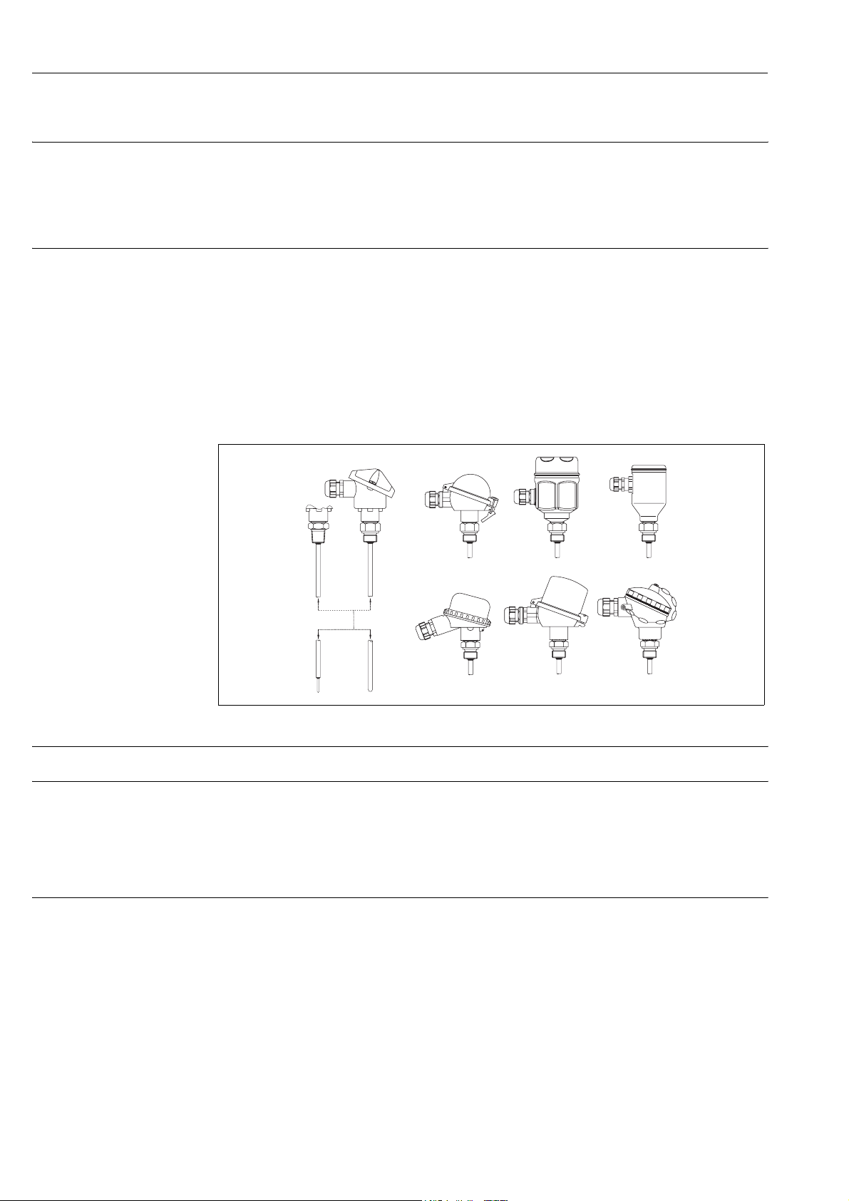
Fig. 1: TR 25 with the various types of heads, process connections and end parts of the probe
Material • Wetted parts in SS 316L/1.0004
Weight From 0.5 to 2 kg for standard options.
Electronics
The required type of output signal can be obtained by choosing the correct head-mounted transmitter.
Endress+Hauser supplies "state-of-the-art" transmitters (the iTEMP® series) built in 2-wire technology and
with 4…20 mA output signal, HART
using a personal computer through the ReadWin® 2000 and FieldCare public domain softwares (for transmitters 4…20 mA and HART®) or the CommuWin II software (for PROFIBUS-PA® transmitters). The HART®
transmitters can also be programmed with the hand-held operating module DXR 275 (Universal HART
municator). A PCP (4…20 mA, TMT 180) model with enhanced accuracy is available. In the case of PROFIBUS-PA® transmitters, E+H recommends the use of PROFIBUS® dedicated connectors. The Weidmüller type
(Pg 13.5 - M12) is provided as a standard option. For detailed information about transmitters, please refer to
the relevant documentation (refer to the TI codes at the end of the document).
If a head-mounted transmitter is not employed, the sensor probe can be connected through the
terminal block to a remote converter (i.e. DIN rail transmitter).
®
or PROFIBUS-PA®. All of the transmitters can be easily programmed
®
Com-
2 Endress+ Hauser
Page 3

omnigrad T TR24
Performance
Operating conditions
Accuracy
Operating condition Product type Material Value or data
Ambient temperature housing without head-mounted transmitter metal housing -40÷130°C
plastic housing -40÷85°C
housing with head-mounted transmitter metal or plastic housing -40÷85°C
housing with display metal housing -20÷70°C
Process temperature Same of measurement range (see below)
Maximum Process pressure 4 MPa (40 bar) at 20°C
Maximum flow velocity The highest flow velocity tolerated by the insert diminishes with increasing lengths of the probe
Shock and vibration resistance According to DIN EN 60751 3 g peak / 10÷500 Hz
exposed to the stream of the fluid.
Probe maximum error type WW - Range: -200 to 600°C
Cl.
A
Cl.
1/3 DIN B
3σ = 0.15+0.0020ItI -200…600°C
3σ = 0.10+0.0017It|
3σ = 0.15+0.0020ItI
-50…250°C
-200...-50 /250…600°C
Probe maximum error type TF - Range: -50 to 400°C
Cl.
A
Cl.
1/3 DIN B
3σ = 0.15+0.0020It|
3σ = 0.30+0.0050ItI
3σ = 0.10+0.0017It|
3σ = 0.15+0.0020ItI
3σ = 0.30+0.0050ItI
-50…250°C
+250…400°C
0…100°C
-50...0/100...250°C
250…400°C
(±3s = range including 99.7% of the readings, |t| = absolute value of the temperature in °C)
Transmitter maximum error: See the corresponding documentation (codes at the end of the document).
Display maximum error:
0.1% FSR + 1 digit (FSR = Full Scale Range).
The "4 wires" configuration, provided as a standard connection for the single Pt 100s, excludes additional
errors in every condition (e.g. high immersion depths, long connecting cables without head-mounted transmitters, ...).
Generally speaking, in the "4 wires" configuration there is a higher guarantee of accuracy.
Response time Tests in water at 0.4 m/s (according to DIN EN 60751; 23 to 33°C step changes):
Diameter of stem Pt 100 bulb type Response time
6 mm TF / WW t50 = 3.5 s
90 = 8 s
t
6 mm / 3 mm reduced TF / WW t
50 = 2 s
90 = 5 s
t
Insulation Insulation resistance between terminals and probe sheath > 100 MOhm at 25°C
(according to DIN EN 60751, test voltage 250 V) > 10 MOhm at 300°C
Self heating Negligible when the E+H iTEMP® transmitters are employed.
Endress+ Hauser 3
Page 4

omnigrad T TR24
aaaaa
aaaaa
aaaaa
aaaaa
aaaaa
a
aaaaa
a
aaaaa
a
aaaaa
a
a
aaaaa
aaaaa
a
a
aaaaa
aaaaa
aaaaa
aaaaa
aaaaa
aaa
aaaaa
a
aaaaa
a
aaaaa
a
aaaaa
a
aaa
aaa
aaa
aaa
a
aaa
a
aaa
a
aaa
a
aaa
a
aaa
a
Installation
The Omnigrad T TR 25 thermometers can be mounted on pipes, vessels or other plant parts that may be necessary, by means of compression junctions or thermowells.
The absence of the extension neck (situated between the process connection and the head) may expose the
housing to overheating. To ensure that the head temperature does not exceed the limit values defined in paragraph "Operating conditions", refer to figure 2.
In the case of ATEX-certified components (transmitter, insert), please refer to the relevant documentation (refer
to the code at the end of this document).
Immersion depth may have an effect on the accuracy of the measurement. If the immersion is too low, an error
may be generated in the temperature recorded due to the lower temperature of the process fluid near to the
walls and heat transfer, which takes place through the sensor stem.
The incidence of such an error can be not negligible if there is a big difference between the process temperature
and the ambient temperature. To avoid measurement errors of this kind, it is advisable to set an immersion
length (L) of at least 50÷70 mm (without thermowell).
In pipes of a small section the axis line of the duct must be reached and if possible slightly exceeded by the tip
of the probe (refer to fig. 3A-3B). Insulation of the outer part of the sensor reduces the effect produced by a low
immersion. Another solution may be a tilted installation (see fig.3C-3D). For use in the food industry, it is best
to follow the rule h <= d/2.
h
d
ML
d
h
ML
Fig. 2: Installation examples
In the case of two-phase flows, pay special attention to the choice of measurement point, as there may be fluctuations in the value of the detected temperature.
With regard to corrosion, the base material of the wetted parts in contact with the fluid (SS 316L/1.4404, compression junction in SS 316/1.4401 or SS 316L/1.4404 and several types of sleeves) can tolerate the common
corrosive media up to even the highest temperatures. For further information on specific applications, please
contact the E+H Customer Service Department. In the case that the sensor components are disassembled, in
the following reassembly procedure the definite torques must be employed.
This will assure the housings with the IP grade protection defined.
When the surrounding environment has a high humidity rate and the process is at low temperature, a plastic
housing is recommended (e.g. model TA20B) to avoid problems due to condensation.
In the case of vibrations the thin film sensing element (TF) may offer advantages, but the
behaviour
depends on
the intensity, the direction and the dominating frequency in the vibration mode.
The wire wound Pt 100 (WW), besides having a larger measurement and accuracy range, guarantees greater
long term stability.
4 Endress+ Hauser
Page 5

omnigrad T TR24
80
110
72
120
113
140
98
108
119
108
95
Ø
1
-
+
-
+
1
System components
Housing The housing, which contains the electric terminals or the transmitter, is available in different types and mate-
rials, e.g. plastic, painted aluminium alloy and stainless steel. The coupling method with the rest of the probe
and the gland for the cable entry ensures a minimum IP65 grade. All available heads have internal geometry
according to DIN 43729 standard (form B), with M24x1.5 thermometer connection. The cable gland is compatible with cables of a diameter between 5 and 9 mm.
Description type IP Dwg Description IP Dwg
TheTA20A is the basic E+H housing for temperature sensors. It is
supplied in the E+H corporate colours.
Material: aluminium alloy
66
67
The TA20B is a black housing,
sometimes referred to as the BBK in
the “Temperature” market with a
screw cap.
Material: polyamide (plastic)
65
120
The TA20D is able to contain a terminal block and a transmitter or
two transmitters at the same time
without terminal block (see THT1table at the end of document).
66 The TA20J is a housing used in
140
other instruments made by E+H.
Material: stainless steel
113
Material: aluminium alloy,
The TA20J (display) is a housing
provided with a LCD display (4 digits), which operates with 4…20
mA transmitters.
Material: stainless steel
66
67
The TA20R is normally recomended by the Temperature division of E+H for hygienic applications.
Material: stainless steel (from bar
stock)
The TA20W is a round blue/grey
coloured with a clip for the cap closure.
Material: aluminium alloy
66 The TA21E is a round blue/grey
140
coloured with a screw cap joined to
the head body with a chain.
85
Material: aluminium alloy
Fig. 3: Type of housings and relative IP grade
Head transmitter The head-mounted transmitters available are (also refer to the "Electronics" section):
Description Dwg
TMT 180 and TMT 181:PCP 4…20 mA. The TMT 180 and the TMT 181
are PC programmable transmitters. The TMT 180 is also available in a version
with enhanced accuracy (0.1°C vs. 0.2°C) in the temperature range 50…250°C and in a version with a fixed measurement range (specified by
the customer in the order phase).
The TMT 182 output consists of 4…20 mA and HART
nals. TMT 182: Smart HART
TMT 184: PROFIBUS-PA
For the TMT 184, with PROFIBUS-PA
®
.
®
.
®
output signal, the communication
®
superimposed sig-
address may be set via software or via mechanical dip-switch.
Ø33
Ø 4.5
6
Ø 4.5
2
3
5
4
Ø33
+
2
-
1
8
6
3
+
-
5
4
66
67
66
67
65
Ø 6.5
Ø44
Ø 6.5
Ø44
Ø55
79
80
Ø44
Ø33
22.5
Ø44
Ø33
26.8
The customer may specify the configuration desired during the order phase.
Process connection Standard connections are available in the below table; Other version may be supplied up on request.
Process connection Dimension (mm) C (mm)
1/2" NPT 8
G 1/2" DIN 15
G 1/2" BSP 15
Endress+ Hauser 5
Page 6

omnigrad T TR24
6
5
4
3
2
1
-
+
-
+
Probe On TR 25 the measurement probe is constituted by a non replaceable mineral insulated insert (MgO) .
The insert length is available in the most commonly used dimensions or can be personalized by the customer
within a range of values (refer to "Sales Structure" at the end of the document).
Although the wiring diagram of single Pt 100 is always supplied with 4 wires configuration, the connection of
a trasmitter can be executed with 3 wires as well, by avoiding to connect whichever of the terminals.
The use of a TR 25 with standard lengths ensures fast delivery times; this allows our customers to reduce the
amount of spare parts to be kept on stock.
THERMOMETER WITH
TERMINAL BLOCK
Ø42
Ø33
red
white
10
@18-20
Gas
ML
THERMOMETER
WITH TRANSMITTER
Ø44
red
white
Ø33
10
@18-20
Gas
ML
THERMOMETER
WITH FLY WIRES
10
@18-20
ML
NPT
ELECTRICAL DIAGRAM
ON TERMINAL BLOCK
2 x Pt 100
white
red
red
white
white
black
black
yellow
3 wires
2 x Pt 100
yellow
yellow
2 wires
1 x Pt 1001 x Pt 100
4 wires
Ø6
Ø6
Ø6
Fig. 4: Functional components and stand ard electrical diagrams (ceramic terminal block)
30
Ø3
6 Endress+ Hauser
Page 7

omnigrad T TR24
Certificates & approvals
PED approval The Pressure Equipment Directive (97/23/CE) is respected. As paragraph 2.1 of article 1 is not applicable to
these types of instruments, the CE mark is not requested for the TR 25 destined for general use.
Material certification Material certifications can be requested separately.
Test report and calibration With regards to the tests and calibration, the "Inspection Report" consists of a compliance declaration for the
essential points of the standard DIN EN 60751.
The "Factory calibration" is carried out in an authorised laboratory EA (European Accreditation) of E+H according to an internal procedure.
The “Evaluation Report” is a calibration that can be applied to sensors with a low immersion length (see the
table below). In this case the procedure accuracy cannot be evaluated because of the low immersion.
A calibration may be requested separately according to an accredited procedure EA (SIT calibration).
Temperature range Minimum immersion length (ML)
Factory calibration -80...-40°C 260 mm
-40...0°C 160 mm
0...250°C 120 mm
250...550°C 300 mm
Evaluation test report 0...140°C 50 mm
Further details
Maintenance The Omnigrad T thermometers do not require any specific maintenance.
In the case of ATEX certified components (transmitter and insert) please refer to the
evant documentation (refer to the code at the end of the document).
Delivery time For small quantities (approximately 10 units) and standard options, between 5 and 15 days depending on the
configuration required.
corresponding
specific rel-
Endress+ Hauser 7
Page 8

Ordering information
omnigrad T TR24
Sales structure
TR25- xxxxxxxxxxxxxxxxxxxxxxxxxx
Thermometer without thermowell. Replaceable mineral insulated inset with Pt 100, in direct contact with process medium.
Fast response time, high accuracy.
Two measurement ranges: from -50 to 400°C (with TF); -200 to 600°C (with WW)
Safety (Ex) certification
Ex certification not required
A
Special version
Y
Head material, conduit, IP grade
TA20A Aluminium, conduit M20x1.5, IP66/IP67
A
TA20A Aluminium,PROFIBUS® connector, IP66
4
TA20A Aluminium, conduit 1/2” NPT, IP66/IP67
2
TA20B Polyamide, black, conduit M20x1.5, IP65
7
TA21E Aluminium, screw cap, M20x1.5, IP65
E
TA20D Aluminium, high cap, conduit M20x1.5, IP66
6
TA20D Aluminium, high cap, PROFIBUS® connector, IP66
5
TA20D Aluminium, high cap, conduit 1/2” NPT, IP66
8
TA20J SS316L, conduit M20x1.5, IP66/IP67
J
TA20J SS316L, with display, conduit M20x1.5, IP66/IP67
K
TA20J SS316L, PROFIBUS® connector, IP66
M
TA20R SS316L, screw cap, conduit M20x1.5, IP66/IP67
R
TA20R SS316L, screw cap, PROFIBUS® connector, IP66
S
TA20W Aluminium, round cap, clip, conduit M20x1.5, IP66
W
Special version
Y
Pipe diameter, type of material
Diameter 3 mm, SS 316L/1.4404
1
Diameter 6 mm, SS 316L/1.4404
2
Diameter 6 mm, reduced 3x50mm, SS 316L/1.4404
5
Process connection
Without process connection
A
Compression fitting TA50 in SS 316/1.4401, G1/2”, sleeve in SS
B
Compression fitting TA50 in SS 316/1.4401, G1/2”, sleeve in PTFE
C
Compression fitting TA50 in SS 316/1.4401, 1/2” NPT, sleeve in SS
D
Compression fitting TA50 in SS 316/1.4401, 1/2” NPT, sleeve in PTFE
E
Weld-in spherical compression fitting TA56 in SS 316L/1.4435, d.25, sleeve in Peek
F
Weld-in cylindrical compression fitting TA70 in SS 316L/1.4404, d.30x34, sleeve in Viton
G
Special version
Y
Immersion length ML (50-3700 mm)
80 mm, immersion length ML
B
120 mm, immersion length ML
D
175 mm, immersion length ML
F
235 mm, immersion length ML
H
275 mm, immersion length ML
K
335 mm, immersion length ML
L
365 mm, immersion length ML
M
425 mm, immersion length ML
N
... mm immersion length ML to specify
X
... mm special immersion length ML
Y
Terminal type or built-in transmitter
Flying leads
F
Ceramic terminal block
C
TMT180-A21AD fixed range, from...to...°C, accuracy 0.2 K span, -50...650°C
2
TMT180-A21AD fixed range, from...to...°C, accuracy 0.1 K span, -50...250°C
3
TMT180-A11 configurable, from...to...°C, accuracy 0.2 K span, -200...650°C
4
TMT180-A11 configurable, from...to...°C, accuracy 0.1 K span, -50...250°C
5
TMT181-A isolated, 2-wire PCP transmitter, configured from ...to ...°C
P
TMT181-B isolated, 2 wire PCP ATEX transmitter, configured from ...to ...°C
Q
HART® transmitter 2-wire TMT182-A, isolated, configured from ...to ...°C
R
HART® ATEX transmitter 2-wires TMT182-B, isolated, configured from ...to ...°C
T
8 Endress+ Hauser
Page 9

omnigrad T TR24
TMT184-A 2-wire PROFIBUS-PA® transmitter, isolated, configured from ...to ...°C
S
TMT184-B 2-wire PROFIBUS®-PA ATEX transmitter, isolated, configured from ...to ...°C
V
THT1, separate item ( see the next THT1 sales structure)
1
RTD type, temperature range, wiring diagram
1 Pt 100, TF Class A, - 50/400°C 4 wires
3
1 Pt 100, TF Class 1/3 DIN B, - 50/400°C 4 wires
7
1 Pt 100, WW Class A, -200/600°C 4 wires
C
1 Pt 100, WW Class 1/3 DIN B, -200/600°C 4 wires
G
2 Pt 100, WW Class A, -200/600°C 3 wires
B
2 Pt 100, WW Class B, -200/600°C 2 wires
D
2 Pt 100, WW Class 1/3 DIN B, -200/600°C 3 wires
F
Special version
Y
Material certification
Material certification not requested
0
Special version
9
Test and calibration on the insert
Test and calibration not requested
0
Inspection report on sensor
1
Inspection report on loop
2
Factory calibration, single RTD, 0-100°C
A
Factory calibration, single RTD, loop 0-100°C
B
Factory calibration, double RTD, 0-100°C
C
Factory calibration, single RTD, 0-100-150°C
E
Factory calibration, single RTD, loop, 0-100-150°C
F
Factory calibration, double RTD, 0-100-150°C
G
Evaluation report, single RTD, 0-100°C
H
Special version
Y
Additional options
Additional options not required
0
Special version
9
xxx- ⇐ Order code (complete)
Endress+ Hauser 9
Page 10

omnigrad T TR24
Sales structure
THT1 Model and version of the head transmitter
TMT180-A11 programmable from...to...°C, accuracy 0.2 K, span limit -200...650°C
A11
TMT180-A12 programmable from...to...°C, accuracy 0.1 K, span limit -50...250°C
A12
TMT180-A21AA fixed range, accuracy 0.2 K, span 0...50°C
A13
TMT180-A21AB fixed range, accuracy 0.2 K, span 0...100°C
A14
TMT180-A21AC fixed range, accuracy 0.2 K, span 0...150°C
A15
TMT180-A21AD fixed range, accuracy 0.2 K, span 0...250°C
A16
TMT180-A22AA fixed range, accuracy 0.1 K, span 0...50°C
A17
TMT180-A22AB fixed range, accuracy 0.1 K, span 0...100°C
A18
TMT180-A22AC fixed range, accuracy 0.1 K, span 0...150°C
A19
TMT180-A22AD fixed range, accuracy 0.1 K, span 0...250°C
A20
TMT180-A21 fixed range, accuracy 0.2 K, span limit -200...650°C, from...to...°C
A21
TMT180-A22 fixed range, accuracy 0.1 K, span limit -50...250°C, from...to...°C
A22
TMT181-A PCP, 2-wire, isolated, programmable from...to...°C
F11
TMT181-B PCP ATEX, 2-wire, isolated, programmable from...to...°C
F21
TMT181-C PCP FM IS, 2-wire, isolated, programmable from...to...°C
F22
TMT181-D PCP CSA, 2-wire, isolated, programmable from...to...°C
F23
TMT181-E PCP ATEX II3D, 2-wire, isolated, programmable from...to...°C
F24
TMT181-F PCP ATEX II3D, 2-wire, isolated, programmable from...to...°C
F25
TMT182-A HART®, 2-wire, isolated, programmable from...to...°C
L11
TMT182-B HART® ATEX, 2-wire, isolated, programmable from...to...°C
L21
TMT182-C HART® FM IS, 2-wire, isolated, programmable from...to...°C
L22
TMT182-D HART® CSA, 2-wire, isolated, programmable from...to...°C
L23
TMT182-E HART® ATEX II3D, 2-wire, isolated, programmable from...to...°C
L24
TMT182-F HART® ATEX II3D, 2-wire, isolated, programmable from...to...°C
L25
TMT184-A PROFIBUS-PA®, 2-wire, programmable from...to...°C
K11
TMT184-B PROFIBUS-PA® ATEX, 2-wire, programmable from...to...°C
K21
TMT184-C PROFIBUS-PA® FM IS, 2-wire, programmable from...to...°C
K22
TMT184-D PROFIBUS-PA® CSA, 2-wire, programmable from...to...°C
K23
TMT184-E PROFIBUS-PA® CSA, 2-wire, programmable from...to...°C
K24
TMT184-F PROFIBUS-PA® ATEX II3D, 2-wire, isolated, programmable from...to...°C
K25
Special transmitter
YYY
Application and services
Assembled into position
1
Special version
9
THT1- ⇐ Order code (complete)
10 Endress+ Hauser
Page 11

omnigrad T TR24
Supplementary documentation
RTD thermometers Omnigrad TST - General information TI088T/02/en
Terminal housings - Omnigrad TA20 TI072T/02/en
Temperature head transmitter iTEMP® Pt TMT180 TI088R/09/en
Temperature head transmitter iTEMP® PCP TMT181 TI070R/09/en
Temperature head transmitter iTEMP® HART® TMT182 TI078R/09/en
Temperature head transmitter iTEMP® PA TMT184 TI079R/09/en
RTD insert for temperature sensors - Omniset TPR100 TI268T/02/en
TA fittings & sockets Omnigrad TA50, TA55, TA60, TA70, TA75 TI091T/02/en
Thermowell for temperature sensors - Omnigrad TW251 TI245T/02/en
Safety instructions for use in hazardous areas XA003T/02/z1
E+H Thermolab - Calibration certificates for
industrial thermometers. RTD and thermocouples TI236T/02/en
Endress+ Hauser 11
Page 12

International Head Quarter
Endress+Hauser
Gmbh+Co.
Instruments International
Colmarer Str.6
P.O. Box 2222
79576 Weil am Rhein
Germany
Tel. +49 76 21 9 75 02
Fax +49 76 21 9 75 34 5
Fax (07621) 975 345
http://www.endress.com
info@ii.endress.com
TI269T/02/en/11.04
60020989
FM+SGML6.0
 Loading...