

Page 1
Technical Information
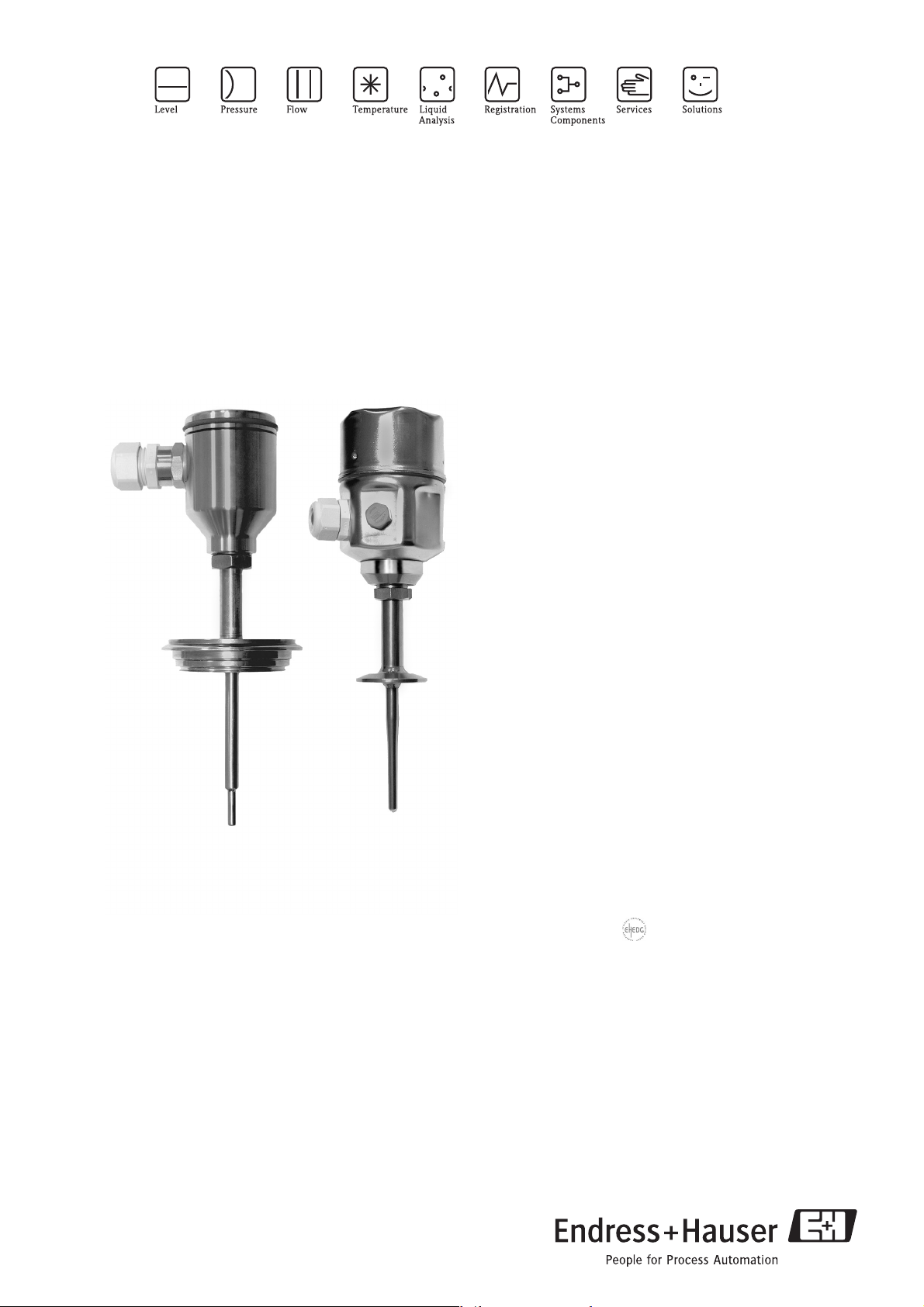
Omnigrad M TR44, TR45
Hygienic, modular RTD assembly,
thermowell for TR45,
various process connections and neck tube
Application
• All hygienic applications for food, pharmaceutical and
fine chemicals industries
• Measuring range: -50...400 °C (-58...752 °F)
• Pressure range up to 40 bar (580 psi)
• Degree of protection: up to IP 68
Head transmitters
All Endress+Hauser transmitters are available with
enhanced accuracy and reliability compared to directly
wired sensors. Easy customizing by choosing one of the
following outputs and communication protocols:
• Analog output 4...20 mA
•HART
•PROFIBUS® PA
• FOUNDATION Fieldbus™
®
Your benefits
• High flexibility due to modular assembly with standard
terminal heads and customized immersion length
• Providing most common hygienic process connections
with EHEDG certification and hygienic design due to
3-A® guidelines
• High accuracy with Pt100 sensors according
to IEC 60751 (class A or better)
• Type of protection for use in hazardous areas:
Intrinsic Safety (Ex ia)
Non-Sparking (Ex nA)
4 5 0
TI244T/02/en
71073141
Page 2
TR44, TR45
Function and system design
Measuring principle These resistance thermometers use a Pt100 temperature sensor according to IEC 60751. This temperature
sensor is a temperature-sensitive platinum resistor with a resistance of 100 Ω at 0 °C (32 °F) and a temperature
coefficient α = 0.003851 °C
There are generally two different kinds of platinum resistance thermometers:
• Wire wound (WW): Here, a double coil of fine, high-purity platinum wire is located in a ceramic support.
This is then sealed top and bottom with a ceramic protective layer. Such resistance thermometers not only
facilitate very reproducible measurements but also offer good long-term stability of the resistance/
temperature characteristic within temperature ranges up to 600 °C (1112 °F). This type of sensor is relatively
large in size and it is comparatively sensitive to vibrations.
• Thin film platinum resistance thermometers (TF): A very thin, ultrapure platinum layer, approx. 1 μm
thick, is vaporized in a vacuum on a ceramic substrate and then structured photolithographically. The
platinum conductor paths formed in this way create the measuring resistance. Additional covering and
passivation layers are applied and reliably protect the thin platinum layer from contamination and oxidation
even at high temperatures.
The primary advantages of thin-film temperature sensors over wire wound versions are their smaller sizes and
better vibration resistance. A relatively low principle-based deviation of the resistance/temperature
characteristic from the standard characteristic of IEC 60751 can frequently be observed among TF sensors at
high temperatures. As a result, the tight limit values of tolerance category A as per IEC 60751 can only be
observed with TF sensors at temperatures up to approx. 300 °C (572 °F). For this reason, thin-film sensors are
generally only used for temperature measurements in ranges below 400 °C (932 °F).
-1
.
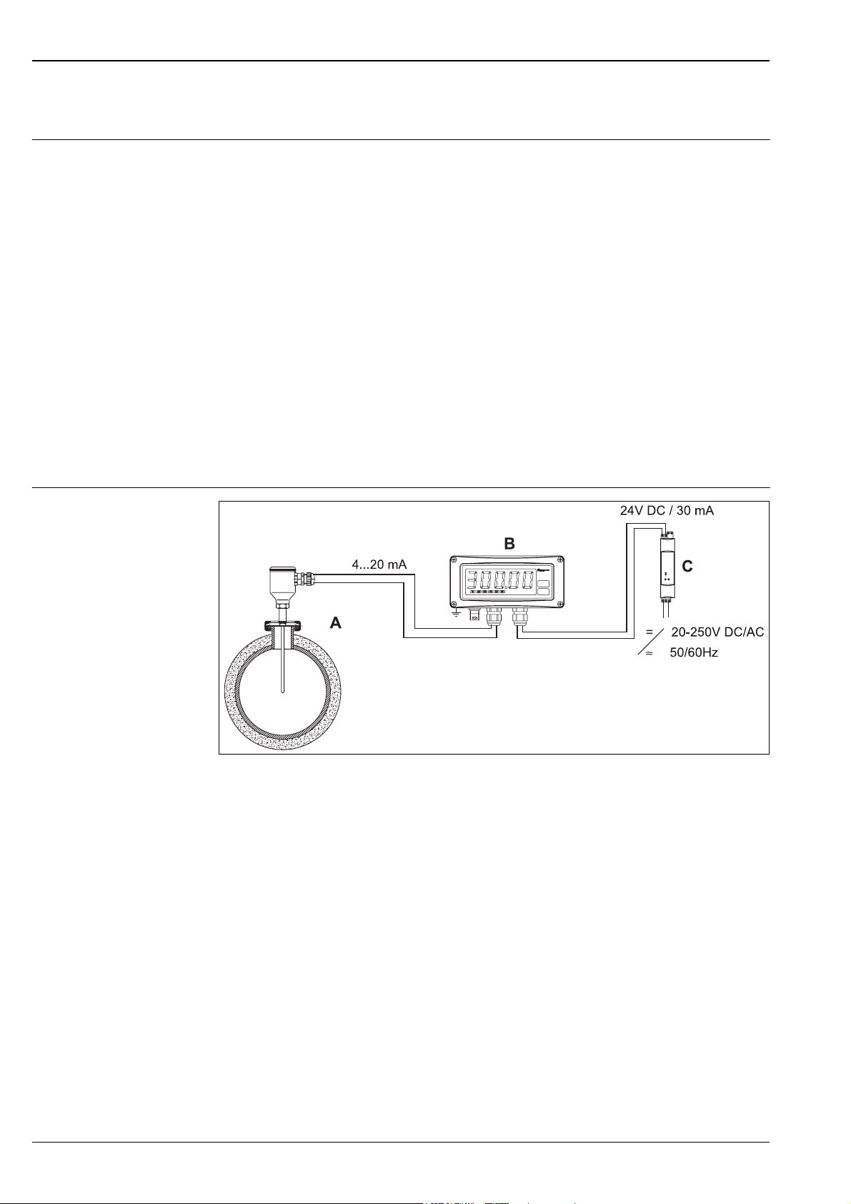
Measuring system
a0008948
Example of an application
A Built-in RTD assembly TR44 or TR45 with head transmitter
B RIA261 Field display
– The display measures an analog measurement signal and indicates this on the display. The display is connected in a
4 to 20 mA current loop and also derives its supply from the loop. The voltage drop is almost negligible (< 2.5 V).
The dynamic internal resistance (load) makes sure that independently from the loop current, the maximum voltage
drop is never exceeded. The analog signal at the input is digitalized, analyzed, and shown in the rear illuminated
display. For details see Technical Information (see chapter "Documentation").
C Active barrier RN221N
– The RN221N active barrier (24 V DC, 30 mA) has a galvanically isolated output for supplying voltage to loop powered
transmitters. The power supply has a wide-range input for mains power, 20 to 250 V DC/AC,
50/60 Hz to be used in any electrical circuit. For details see Technical Information (see chapter "Documentation").
2 Endress+Hauser
Page 3
TR44, TR45
Equipment architecture
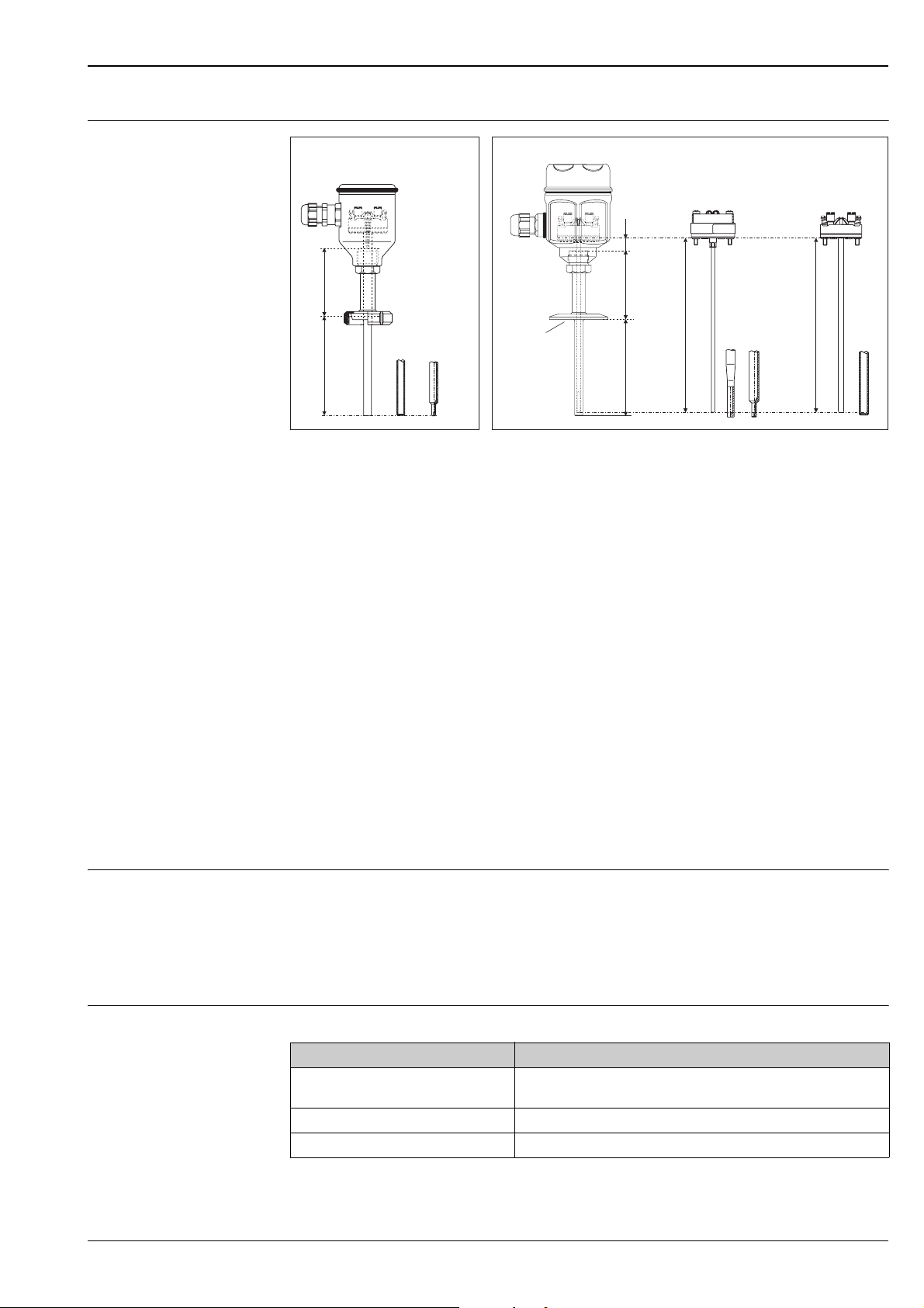
TR44
3
E
4
5
L
666a 6b 6c
Equipment architecture of the Omnigrad M TR44 (non-replaceable insert) and TR45 (replaceable insert)
12Insert (∅ 3 mm, 0.12 in) with mounted head
transmitter, for example
Insert (∅ 6 mm, 0.24 in) with mounted
ceramic terminal block, for example
3 Various terminal heads E Neck tube
4 Protection armature L Immersion length
5 Various hygienic process connections, detailed
information see chapter ’process connection’
TR45
3
10 mm
(0.4 in)
E
5
L
6
6a
6b
6c
IL TR45 Insertion length = E + L + 10 mm (0.4 in)
E
4
L
Various tip shapes, detailed information see chapter ’tip shape’:
Straight and reduced for TR44
Tapered and reduced for TR45 inserts with ∅ 3 mm (0.12 in)
Straight for TR45 inserts with ∅ 6 mm (0.24 in)
12
IL
IL
a0009567
The RTD assemblies Omnigrad M TR44 and TR45 are built up for hygienic processes and the main
requirements regarding "Cleaning-in-process" (CIP) and "Sterilization-in-process" (SIP). The architecture is
according to 3-A
®
standard. The hygienic process connections are easy to clean and thus they are complient
with EHEDG. The thermometers can be installed in the process (pipe or tank) using a hygienic process
connection. The most common process connections are available.
• Omnigrad M TR44 RTD assemblies consist of a terminal head and a protection armature with integrated
insert. With a diameter of 6 mm (0.24 in) resp. 8 mm (0.31 in) reduced to 5.3 mm (0.21 in) at the tip, it is
possible to realize best thermal response times. Insert and neck tube are welded together. The hygienic
process connection is also fixed connected to the neck tube.
• The Omnigrad M TR45 RTD assemblies are constructed in three modules: terminal head, protection
armature and a replaceable insert. The protection armature consists of a neck tube, process connection
welded between neck tube and integrated thermowell.
Measurement range • TR44: -50 °C…250 °C (-58 °F...482 °F)
• TR45: -50 °C…400 °C (-58 °F...752 °F)
Performance characteristics
Operating conditions Ambient temperature
Terminal head Temperature in °C (°F)
Without mounted head transmitter Depends on the terminal head used and the cable gland or fieldbus connec-
With mounted head transmitter -40 to 85 °C (-40 to 185 °F)
With mounted head transmitter and display -20 to 70 °C (-4 to 158 °F)
tor, see 'Terminal heads' section, → ä 9
Endress+Hauser 3
Page 4

TR44, TR45
Permitted process pressure at the protection armature
The maximum process pressure is 40 bar (600 psi). It is limited further by the process connection in question.
See → ä 13.
Permitted flow velocity depending on the immersion length
The highest flow velocity tolerated by the thermometer diminishes with increasing immersion length exposed
to the stream of the fluid. In addition it is dependent on the diameter of the thermometer tip, on the kind of
measuring medium, on the process temperature and on the process pressure. The following figures exemplify
the maximum permitted flow velocities in water and superheated steam at a process pressure of 4 MPa
(40 bar = 580 PSI).
Maximum flow velocity TR44
A Medium water at T = 50 °C (122 °F) L Immersion length
B Medium superheated steam at T = 400 °C (752 °F) v Flow velocity
a0008065-en
a0008967
Maximum flow velocity TR45
– Tube diameter 9 x 1 mm (0.35 in) -----------
A Medium water at T = 50 °C (122 °F) L Immersion length
B Medium superheated steam at T = 400 °C (752 °F) v Flow velocity
4 Endress+Hauser
Page 5

TR44, TR45
Shock and vibration resistance 4g / 2 to 150 Hz as per IEC 60068-2-6
Accuracy RTD corresponding to IEC 60751
Class max. Tolerances
(°C)
Temperature
range
RTD maximum error type TF - range: -50 to +400 °C
Cl. A ± (0.15 + 0.002 · |t|1)) -50 °C to +250 °C
C. AA, former
± (0.1 + 0.0017 · |t|1)) 0 °C to +150 °C
1/3 Cl. B
Cl. B ± (0.3 + 0.005 · |t|
1)
) -50 °C to +400 °C
Characteristics
2)
a0008965-en
1) |t| = absolute value °C
2) For TR44: -50 °C to 200 °C
!
Note!
For measurement errors in °F, calculate using equations above in °C, then multiply the outcome by 1.8.
Response time Tests of the sensor assemblies without transmitter in water at 0.4 m/s (1.3 ft/s), according to IEC 60751;
10 K temperature step change; For immersion length L > 45 mm (1.77 in):
Thermometer TR44 without thermowell
Outer diameter Response time Reduced tip ∅ 5.3 mm (0.2 in) Straight tip ∅ 6 mm (0.24 in)
8 mm (0.31 in) t
t
6 mm (0.24 in) t
t
TR45 with thermowell
Diameter Response
time
9 x 1 mm
(0.35 in)
t
50
t
90
50
90
50
90
Reduced tip
∅ 5.3 mm (0.2 in)
1)
A
7.5 s
21 s
≤ 3 s
≤ 7 s
not available
not available
2)
B
3.5 s
8 s
Tapered tip
∅ 6.6 mm (0.26 in)
A
11 s
37 s
1)
2)
B
5 s
12 s
not available
not available
≤ 4s
≤ 10 s
Straight tip
∅ 9 mm (0.35 in)
1)
A
18 s
55 s
2)
B
10 s
30 s
1) without thermally conductive paste
2) with thermally conductive paste
Endress+Hauser 5
Page 6
TR44, TR45
Insulation resistance Insulation resistance ≥100 MΩ at ambient temperature.
Insulation resistance between each terminal and the sheath is measured with a voltage of 100 V DC.
Self heating RTD elements are passive resistances that are measured using an external current. This measurement current
causes a self heating in the RTD element itself which in turn creates an additional measurement error. In
addition to the measurement current the size of the measurement error is also affected by the temperature
conductivity and flow velocity of the process. This self heating error is negligible when an Endress+Hauser
®
temperature transmitter (very small measurement current) is connected.
iTEMP
Calibration specifications Endress+Hauser provides comparison temperature calibration from -50 to +400 °C (-58 to 752 °F) based on
the International Temperature Scale (ITS90). Calibrations are traceable to national and international standards.
The calibration report is referenced to the serial number of the thermometer.
TR44 (the complete thermometer is calibrated)
TR45 (only the measurement instert is calibrated)
Temperature range without head transmitter with head transmitter
-80 °C < -40 °C (-110 °F < -40 °F) 200 (7.9)
-40 °C to 0 °C (-40 °F to 32 °F) 160 (6.3)
0 °C to 250 °C (32 °F to 480 °F) 120 (4.7) 150 (5.9)
250 °C to 400 °C (480 °F to 752 °F) 300 (11.8)
Material Extension neck and thermowell
The temperatures for continuous operation specified in the following table are only intended as reference values
for use of the various materials in air and without any significant compressive load. The maximum operation
temperatures are reduced considerably in some cases where abnormal conditions such as high mechanical load
occur or in aggressive media.
Material
name
AISI 316L/
1.4404
1.4435
Short form Recommended max.
temperature for
continuous use in air
650 °C (1200 °F)
X2CrNiMo17-12-2
X2CrNiMo18-14-3
1)
Properties
• Austenitic, stainless steel
• High corrosion resistance in general
• Particularly high corrosion resistance in chlorine-based and acidic, non-oxidizing
atmospheres through the addition of molybdenum (e.g. phosphoric and sulfuric acids, acetic
and tartaric acids with a low concentration)
• Increased resistance to intergranular corrosion and pitting
• Compared to 1.4404, 1.4435 has even higher corrosion resistance and a lower delta ferrite
content
Minimum standard immersion length L in mm (inch)
(thermometer without neck)
1) Can be used to a limited extent up to 800 °C (1472 °F) for low compressive loads and in non-corrosive media. Please contact your Endress+Hauser sales team
for further information.
Transmitter specifications
TMT180
PCP
Pt100
Measurement accuracy 0.2 °C (0.36 °F), optional
0.1 °C (0.18 °F) or 0.08%
% is related to the adjusted measurement range (the larger value applies)
Sensor current Ι ≤ 0.6 mA Ι ≤ 0.2 mA Ι ≤ 0.3 mA
Galvanic isolation (input/output) - Û = 2 kV AC
TMT181
PCP
Pt100, TC, Ω, mV
0.2 °C (0.36 °F) or 0.08% 0.1 °C (0.18 °F)
TMT182
®
HART
Pt100, TC, Ω, mV
TMT84 PA / TMT85 FF
Pt100, TC, Ω, mV
6 Endress+Hauser
Page 7

TR44, TR45
System components
Family of temperature transmitters
Thermometers fitted with iTEMP® transmitters are an installation ready complete solution to improve
temperature measurement by increasing accuracy and reliability, when compared to direct wired sensors, as
well as reducing both wiring and maintenance costs.
PC programmable head transmitter TMT180 and TMT181
They offer a high degree of flexibility, thereby supporting universal application with low inventory storage. The
®
transmitters can be configured quickly and easily at a PC. Endress+Hauser offers the ReadWin® 2000
iTEMP
configuration software for this purpose. This software can be downloaded free of charge at
www.readwin2000.com. More information can be found in the Technical Information (see
"Documentation" section).
®
TMT182 head transmitter
HART
HART® communication is all about easy, reliable data access and getting additional information about the
measurement point more inexpensively. iTEMP® transmitters integrate seamlessly into your existing control
system and provide painless access to numerous diagnostic information.
Configuration with a hand-held (Field Xpert SFX100 or DXR375) or a PC with configuration program
(FieldCare, ReadWin
®
2000) or configure with AMS or PDM. Details see Technical Information (see chapter
’Documentation’).
Type of transmitter Specification
®
iTEMP
TMT18x
• Material: Housing (PC), Potting (PUR)
• Terminals: Cable up to max. max. ≤ 2.5 mm
with wire end ferrules
• Eyelets for easy connection of a HART
clips
• Degree of protection NEMA 4 (see also type of terminal head)
Details see Technical Information (see chapter ’Documentation’)
2
/ 16 AWG (secure screws) or
®
-handheld terminal with alligator
R09-TMT182ZZ-06-06-xx-en-001
®
PROFIBUS
Universally programmable head transmitter with PROFIBUS
PA TMT84 head transmitter
®
PA communication. Converting various input
signals into a digital output signal. High accuracy over the complete ambient temperature range. Swift and easy
operation, visualization and maintenance using a PC directly from the control panel, e. g. using operating
software such as FieldCare, Simatic PDM or AMS.
Benefits are: dual sensor input, highest reliability in harsh industrial environments, mathematic functions,
thermometer drift monitoring, sensor back-up functionality, sensor diagnosis functions and sensor-transmitter
matching using Callendar-Van Dusen coefficients. Details see Technical Information (see chapter
’Documentation’).
FOUNDATION Fieldbus™ TMT85 head transmitter
Universally programmable head transmitter with FOUNDATION fieldbus™ communication. Converting
various input signals into a digital output signal. High accuracy over the complete ambient temperature range.
Swift and easy operation, visualization and maintenance using a PC directly from the control panel, e. g. using
operating software such as ControlCare from Endress+Hauser or the NI Configurator from National
Instruments.
Benefits are: dual sensor input, highest reliability in harsh industrial environments, mathematic functions,
thermometer drift monitoring, sensor back-up functionality, sensor diagnosis functions and sensor-transmitter
matching using Callendar-Van Dusen coefficients. Details see Technical Information (see chapter
’Documentation’).
Endress+Hauser 7
Page 8

Type of transmitter Specification
®
iTEMP
TMT84 and TMT85
• Spring range L ≥ 5 mm (0.2"), see Pos. A
• Fixing elements for pluggable measured value display, see Pos. B
• Interface for contacting measured value display, see Pos. C
• Material (RoHS-compliant)
Housing: PC
Potting: PU
•Terminals:
Screw terminals (cable up to max. ≤ 2.5 mm
or spring terminals (e. g. from 0.25 mm
for flexible wires with wire-end ferrules with plastic ferrule)
• Degree of protection NEMA 4 (see also type of terminal head)
a0007301-en
Details see Technical Information (see chapter ’Documentation’)
Pluggable display TID10 as option
• Displays the actual measured value and the measurement point identification
• Displays fault events in inverse color with channel ident and diagnostics code
• DIP-switches on the rear for hardware set-up, e. g. PROFIBUS
address
Note!
!
Display is only available with suitable terminal head with display window, e.g.
TA30
TR44, TR45
2
/ 16 AWG)
2
to 0.75 mm2/ 24 AWG to 18 AWG
®
PA bus
a0009955
8 Endress+Hauser
Page 9
TR44, TR45
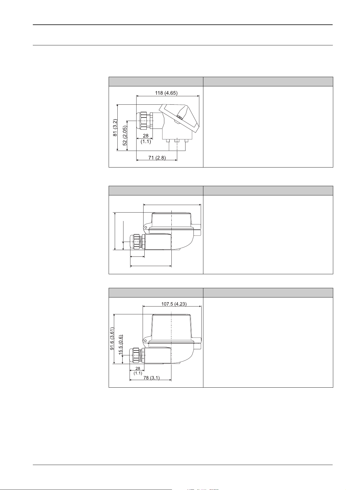
Terminal heads All terminal heads have internal geometry according to DIN 43729, form B and thermometer connection
M24x1.5.
All dimensions in mm (inch). All cable gland dimensions in the graphics are based on SKINTOP ST M20x1.5
TA20A Specification
• Degree of protection: IP66
• Max. temperature: 100 °C (212 °F)
• Material: aluminum alloy, rubber seal under the cover
• Cable entry: G ½", NPT ½" or M20x1.5; plug: M12x1 PA
• Protection armature connection: M24x1.5, NPT ½" or G ½"
• Head color: blue RAL 5012, epoxy resin coating
• Cap color: grey RAL 7035, epoxy resin coating
• Weight: 180 g (6.35 oz)
®
•3-A
marked
a0008650
TA30A Specification
107.5 (4.23)
• Degree of protection: IP66/68
• Max. temperature: 150 °C (300 °F)
• Material: aluminum, polyester powder coated
Seals: silicone
• Cable entry incl. glands: ½" NPT and M20x1.5, only thread: G ½",
plugs: M12x1 PA, 7/8" FF
70 (2.76)
15.5 (0.6)
• Protection armature connection: M24x1.5
• Head color: blue RAL 5012
• Cap color: grey RAL 7035
28
(1.1)
• Weight: 330 g (11.64 oz)
78 (3.1)
a0009820
TA30A with display window Specification
• Degree of protection: IP66/68
• Max. temperature: 150 °C (300 °F)
• Material: aluminum, polyester powder coated
Seals: silicone
• Cable entry incl. glands: ½" NPT and M20x1.5, only thread: G ½",
plugs: M12x1 PA, 7/8" FF
• Protection armature connection: M24x1.5
• Head color: blue RAL 5012
• Cap color: grey RAL 7035
• Weight: 420 g (14.81 oz)
• Head transmitter optional with TID10 display
a0009821
Endress+Hauser 9
Page 10

TA30D Specification
• Degree of protection: IP66/68
• Max. temperature: 150 °C (300 °F)
• Material: aluminum, polyester powder coated
Seals: silicone
• Cable entry incl. glands: ½" NPT and M20x1.5, only thread: G ½",
plugs: M12x1 PA, 7/8" FF
• Protection armature connection: M24x1.5
• Two head transmitters can be mounted. In the standard version,
one transmitter is mounted in the terminal head cover and an
additional terminal block is installed directly on the insert.
• Head color: blue RAL 5012
• Cap color: grey RAL 7035
• Weight: 390 g (13.75 oz)
a0009822
TA20B Specification
• Degree of protection: IP65
• Max. temperature: 80 °C (176 °F)
• Material: polyamide (PA)
• Cable entry: M20x1.5
• Head and cap color: black
• Weight: 80 g (2.82 oz)
®
•3-A
marked
TR44, TR45
a0008663
TA21E Specification
• Degree of protection: IP65
• Max. temperature: 130 °C (266 °F) silicone, 100 °C (212 °F)
rubber (observe max. permitted temperature of the cable gland!)
• Material: aluminum alloy with polyester or epoxy coating; rubber
or silicone seal under the cover
• Cable entry: M20x1.5 or plug M12x1 PA
• Protection armature connection: M24x1.5, G ½" or NPT ½"
• Head color: blue RAL 5012
• Cap color: grey RAL 7035
• Weight: 300 g (10.58 oz)
®
•3-A
marked
a0008669
10 Endress+Hauser
Page 11

TR44, TR45
TA20J Specification
• Degree of protection: IP66/IP67
• Material: 316L (1.4404) stainless steel, rubber seal under the
cover (hygienic design)
• 4 digits 7-segments LC display (loop powered with 4...20 mA
transmitter)
• Cable entry: ½" NPT, M20x1.5 or plug M12x1 PA
• Protection armature connection: M24x1.5 or ½" NPT
• Head and cap color: stainless steel, polished
• Weight: 650 g (22.93 oz) with display
• Humidity: 25 to 95%, no condensation
®
•3-A
marked
The programming is executed through 3 keys at the bottom of the
display.
a0008866
* dimensions with optional display
TA20R Specification
• Degree of protection: IP66/67
• Max. temperature: 100 °C (212 °F)
• Material: SS 316L (1.4404) stainless steel
• Cable entry: ½" NPT, M20x1.5 or plug M12x1 PA
• Head and cap color: stainless steel
• Weight: 550 g (19.4 oz)
•LABS - free
®
3-A
marked
a0008667
Maximum ambient temperatures for cable glands and fieldbus connectors
Type Temperature range
Cable gland ½" NPT, M20x1.5 (non Ex) -40 to +100 °C (-40 to +212 °F)
Cable gland M20x1.5 (for dust ignition-proof area) -20 to +95 °C (-4 to +203 °F)
Fieldbus connector (M12x1 PA, 7/8" FF) -40 to +105 °C (-40 to +221 °F)
Endress+Hauser 11
Page 12

Assembly All dimensions in mm (inches).
TR44, TR45
Dimensions of the Omnigrad M TR44 and TR45
A Model with terminal block mounted ∅ ID Insert diameter
B Model with head transmitter mounted IL TR45 insertion length = E + L + 10 mm (0.4 in)
C Model with flying leads L Immersion length
d Neck tube diameter ∅ X Thermowell diameter
E Neck tube length
Tip shape
TR44
20 (0.8)
R
Ø9x1
(0.35)
Ø5.3 (0.21)
S
Ø6 (0.35)
R
Ø8 (0.31)
20 (0.8)
3 (0.12)
Ø5.3 (0.21)
3.2
(0.13)
Available versions of thermowell tips (reduced, straight or tapered)
3.2
3 (0.12)
(0.13)
TR45
S
Ø9x1
(0.35)
1 (0.94)
Ø7 (0.28)
T
Ø9x1
(0.35)
20
40 (1.6)
~3.5
(0.8)
(0.14)
3
Ø6.6 (0.26)
a0008961
(0.12)
a0009560
Pos. No. Tip shape, L = Immersion length Insert Diameter
TR44-S Straight for ∅ 6 mm (0.24 in) not available
TR44-R Reduced for ∅ 8 mm (0.32 in) not available
TR45-R Reduced, L ≥ 30 mm (1.2 in) ∅ 3 mm (0.12 in)
TR45-S Straight ∅ 6 mm (0.24 in)
TR45-T Tapered, L ≥ 65 mm (2.6 in) ∅ 6 mm (0.24 in)
12 Endress+Hauser
Page 13

TR44, TR45
Weight From 0.5 to 2.5 kg (1 to 5.5 lbs) for standard options.
Process connection All dimensions are in mm. Surface finishing Ra ≤ 0.8 μm, ≤ 0.4 μm or ≤ 0.4 μm electropolished.
DIN 11851 (milk pipe connection, 3-A® marked)
B
C
A
L
d
D
d
R0.4
2
a0009561
1
R0.4
1 Centering ring
2 Gasket
Note!
!
Only allowed with self centering gasket
DIN 11864-1 Form A (aseptic connection, 3-A® marked)
(*) All dimensions are in mm (***)
DN
DIN 11851
(**) All dimensions are in mm (***)
DN
Inches
1 ¼” 36 50 29,3
1½” 42 56
(*) Pipes according to DIN 11850
(**) Not included in DIN 11851 standard
(***) With a suitable gasket, up to 140°C.
AB C d
25 30 44 26
10
40 42 56
AB C d
1” 30 44 22,9
2” 54 68 11 47,8
38
10
35,1
D
lightDnormalDstrong
--30
-29-
28 - -
--36
-35-32 36 50 32
34 - -
--42
-41-
40 - -
--54
-53-50 54 68 11 50
52 - -
D
normalDlight
35 -
- 25,4
41 -
- 31,8
48 -
- 38,1
61 -
- 50,8
PN max
(bar)
40
25 CG CG
PN max
TR44- TR45-
TR44- TR45-
(bar)
CD CD
CE CE
40
CF CF
25 CG CG
CD CD
CE CE
CF CF
B
C
L
(*) (****)
DN
DIN 11864-1
BC d
25 42,9 9 26
40 54,9 10 38
D
NormalDstrong
-30
29 -
-42
41 -
PN max
(bar)
40
50 66,9 11 50 53 - 25 - -
TR 44- TR 45
CH CH
CJ CJ
-
(**) (****)
D
d
d
a0009562
DN
ISO BS
25 21,8 25,0
25,4
BC d D
42,9 9
22,2 25,4
38 54,9 10 34,8 38,0
PN max
(bar)
40
TR44- TR45-
CH CH
CJ CJ
(***) (****)
DN
DIN EN ISO
BC d D
26,9 42,9 9 23,7 26,9 CH CH
42,4 54,9 10 38,4 42,4
PN max
(bar)
40
TR44- TR45-
CJ CJ
(*) Pipes according to DIN 11850.
(**) Pipes according to ISO 2037 and BS 4825 Part 1.
(***) Pipes according to DIN EN ISO 1127.
(****) With a suitable gasket, up to 140°C.
Endress+Hauser 13
Page 14

Varivent® connection (3-A® marked)
Type B (DN10/DN15)
L
V
Type F (DN25, 1")
Type N (DN32...125, 1¼"...6")
d
a0009563
(*)
DN metric d D V PN (bar) TR44- TR45- Type
10 10 14
15 16 20
25 26 30 50 FB FB F
40 38 42
50 50 54
65 66 70
80 81 85
D
100 100 104
125 125 129
(**)
DN ISO d D V PN (bar) TR44- TR45- Type
25 29,7 33,7
32 38,4 42,4
40 44,3 48,3
50 56,3 60,3
(***)
DN inches d D V PN (bar) TR44- TR45- Type
1” 22,2 25,4 50 FB FB F
1 ½” 34,9 38,1
2” 47,6 50,8
2 ½” 60,3 63,5
3” 73,0 76,1
4” 97,6 101,6
31 FC FC B
25
16
68
10
68 25 FA FA N
25
68
16
10
FA FA N
FA FA N
TR44, TR45
L
V
ISO 2852 clamp connection (3-A® marked)
(****)
DN IPS d D V PN (bar) TR44- TR45- Type
d
a0009564
a0009565
D
2” 57,1 60,3 25
3” 84,7 88,9 16
4” 110,1 114,4
6” 162,3 168,3
(*) Pipes according to DIN 11850.
(**) Pipes according to DIN EN ISO 1127.
(***) Pipes according to ISO 2037 and BS 4825 Part 1.
(****) Pipes according to IPS Sch. 5.
(*) (****)
DN
ISO 2852
8÷18(**)
12(***)
12,7(***)
17,2(***)
21,3(***)
25
33,7
38
40
51
(*) Pipes according to ISO 2037 and BS 4825 Part1.
(**) MicroClamp (not included in std. ISO 2852); not standard pipes.
(***) MiniClamp.
(****) Depends on clamping ring type, at 121°C with suitable gasket.
AB C dDExpanded
20,0 25,0 3,6
27,5 34,0
43,5 50,5
56,5 64,0
68
2,85
10
(**) (**) (**)
12 16 12,7 16,7 17,2 21,2 21,3 25,3 -
25 29 22,6 - 25,6
33,7 38,1 31,3 - 34,3
38 42,4 35,6 - 38,6
40 44,8 37,6 - 40,6
51 55,8 48,6 - 51,6
FA FA N
type
Welded
type
D
PN max
(bar)
16
TR44- TR45-
BM -
BA BA
BB BB
BC BC
14 Endress+Hauser
Page 15

TR44, TR45
L
Tri-clamp® connection (3-A® marked)
B
C
L
A
d
B
C
L
d
A
MicroClamp
SMS 1147/8 connection (3-A® marked)
(*) (**)
DN A B C d
d
a0009566
½”(***)
¾”(***)
1” 22,2
1½”
2” 56,5 64,0
(*) Pipes according to ISO 2037 and BS 4825 Part1.
D
(**) Depends on clamping ring type, at 121°C with suitable gasket.
(***) MicroClamp.
20,0 25,0 3,6
43,5 50,5
1 Counterpart connection
2 Gasket
3 Groove slip-on nut
Note!
!
Counterpart must fix gasket in position.
D
std.Dstrong
9,5 - 12,7 - -
15,8 - 19,0 -
34,9
2,85
47,6
- 29,5 -
25,4 - 9÷20,7
- 42,6 -
38,1 - 9÷20,7
- 55,7 -
50,8 - 9÷17,2
PNmax
(bar)
TR44- TR45-
BM
-
BF BF
BH BH
Weld-in cylindrical (30x40 mm, 3-A
30 (1.18)
Liquiphant M G1" (3-A
®
marked)
®
marked)
40 (1.57)
L
a0009568
Weld-in spherical (30x40 mm, 3-A® marked)
30 (1.18)
R.15
a0009569
(0.6)
Ingold (not 3-A® marked)
a0009572
25x50 mm
25x30 mm
Conical connection metal-to-metal G½"
®
(not 3-A
40 (1.57)
L
a0009570
"
Maximum process pressure P = 16 bar (232 psi)
Conical connection metal-to-metal M12x1.5 (not
3-A
L
a0009573
®
marked)
marked)
Caution!
5
11
8
14
20 (0.8)
(0.2)
(0.43)
(0.31)
(0.55)
(0.71)
M12 1.5x
(0.3)
10 (0.4)
G½”
18
7.5
3 (0.12)
3 (0.12)
L
2 (0.08)
7.6 (0.3)
37 (1.46)
a0009571
21 (0.83)
L
a0009574
Endress+Hauser 15
Page 16

!
TR44, TR45
Standard connections are available in several sizes. Others (i.e. Neumo, APV) are available on request. The
process connection is continuously welded on the probe or on the well so as to obtain a minimum welding
radius of 3.2 mm (0.13 in) between the lower surface of the connection and the sensor stem (according to
EHEDG and 3-A
Please refer to chapter ’Accessories’ for information regarding availability of welding adaptors. The Varivent®
connections must be used with dedicated Tuchenhagen
flanges with small nominal diameter, maximum immersion lengths for usual applications are listed in the
following table (also refer to chapter ’Installation conditions’).
Note!
Care should be taken by the user in the execution of the welding on the process side (suitable weld material,
welding radius > 3.2 mm, absence of pits, folds, crevices, …).
®
standards).
®
in-line components or tank adaptors. For Varivent®
Thermometers TR44
(6 mm/0.24 in probe, straight tip)
®
Varivent
Suggested immersion length
(L)
nominal diameter DN 10/15 DN 25 DN 10/15 DN 25
30 to 50 mm (1.18 to 2 in)
for low viscosity fluids
17 mm (0.7 in)
for high viscosity fluids
17 mm
(0.7 in)
TR45 (reduced tip)
30 mm (1.18 in)
for low viscosity fluids
17 mm (0.7 in)
for high viscosity fluids
Spare parts • A thermowell for TR45 is available as spare part TW45 (see Technical Information in chapter
’Documentation’).
• The RTD insert is available as spare part TPR100 (see Technical Information in chapter ’Documentation’).
In TR45, the measuring probe is constituted by a mineral insulated insert positioned inside the thermowell. For
its replacement, the insert length (IL) must be chosen depending on the immersion length (L). If spare parts are
required, refer to the following table:
Thermowell tip shape ID Neck tube length E Insertion length IL
Straight (version S) 6 mm (0.24 in)
Reduced/tapered on Ø 9 mm
(0.35 in), version R/T
3 mm (0.12 in)
Standard 85 mm (3.45 in) or as specified
IL = L + E + 10 mm
(0.4 in)
17 mm
(0.7 in)
16 Endress+Hauser
Page 17

TR44, TR45
Wiring
Electrical connection cables must comply with 3-A® standard, must be smooth, corrosion resistant and
cleanable.
Wiring diagrams Type of sensor connection
Head mounted transmitter TMT18x (single input)
Head mounted transmitter TMT84 and TMT85 (dual input)
Terminal block mounted
T09-TH1112xx-04-xx-XX-ae-000
a0008848-en
a0008591-en
Endress+Hauser 17
Page 18

TR44, TR45
Installation conditions
Orientation No restrictions, but self draining. If applicable leak detection hole must be at the lowest point.
Installation instructions The immersion length of the thermometer influences the accuracy. If the immersion length is too small then
errors in the measurement are caused by heat conduction via the process connection and the container wall.
If installing into a pipe then the immersion length must be half of the pipe diameter, ideally.
• Installation possibilities: Pipes, tanks or other plant components
• Minimum immersion length = 80 to 100 mm (3.15 to 3.94 in)
The immersion length should correspond to at least 8 times of the thermowell diameter. Example:
Thermowell diameter 12 mm (0.47 in) x 8 = 96 mm (3.8 in). A standard immersion length of 120 mm (4.72
in) is recommended
• ATEX certification: Always take note of the installation regulations!
!
Note!
When operating in small nominal bore pipes it must be guaranteed that the thermowell tip is extending far
enough into the process to reach out past the pipe center line (see Pos. A and B). A further solution could be
an angled (tilted) installation (see Pos. C and D). When determining the immersion length all thermometer
parameters and the process to be measured must be taken into account (e.g. flow velocity, process pressure).
a0008946
General installation solutions
A - B: In pipes with a small cross section the sensor tip should reach or extend slightly past the center line of the pipe (=
L). Installation with minimal 3° inclination because of self draining.
C - D: Tilted installation.
18 Endress+Hauser
Page 19

TR44, TR45
Sensor with
milk pipe
connection
Groove
slip-on nut
Companion
connection
Centering ring
R0.4 R0.4
ABCD
Sensor with
Varivent connection
Companion
connection
O-Ring
Sealing
Shaped
gasket
Companion
connection
Detailed installation instructions
A Milk pipe connection as per DIN 11851 only in linkage
EHEDG certified and self centering ring
BVarivent
®
- process connection D Liquiphant-M G1" process connection,
C Clamp as per ISO 2852
horizontal installation
Welding boss
Leak detection hole
Vessel wall
Gasket
(O-ring)
a0011758-en
a0008947
Process connections for installation in small pipes
AVarivent® - process connection D = 50 mm for pipes DN25 C Clamp or micro-clamp
BVarivent
®
- process connection D = 31 mm for pipes DN10/15
The matches for the process connections as well as the gaskets are not included in the scope of delivery of this
assembly. Welding adapter for Liquiphant M G1"- and Ingold process connections with associated o-ring sets
are available as accessories → ä 25.
Care should be taken by the user in the execution of the welding on the process side (suitable weld material,
welding radius > 3.2 mm, absence of pits, folds, crevices, …). As a general rule, the assemblies should be
installed in such a way that does not adversely affect their cleanability (3-A
®
requirements must be adhered
to). The required flush-mounting can be achieved by the connection Varivent®, Liquiphant type M G1" (+
weld-in adapter) and Ingold (+ weld-in adapter).
Neck tube length The neck tube is the part between the process connection and the housing. It is normally made of a tube with
dimensional and physical characteristics (diameter and material) which are the same of the tube in contact with
the medium. The connection situated in the upper part of the neck allows for orientation of the terminal head.
The heating of the terminal head consequent to the process temperature is negligibly small if the process
temperature does not exceed the measuring range of TR44 and TR45.
• Standard neck tube diameter: 15 mm (0.6 in)
• Standard neck tube length:
– TR44: 82 mm (3.23 in)
– TR45: 85 mm (3.45 in)
Endress+Hauser 19
Page 20

TR44, TR45
Certificates and approvals
CE Mark The device meets the legal requirements of the EC directives if applicable. Endress+Hauser confirms that the
device has been successfully tested by applying the CE mark.
Hazardous area approvals For further details on the available Ex versions (ATEX, CSA, FM, etc.), please contact your nearest
Endress+Hauser sales organization. All relevant data for hazardous areas can be found in separate Ex
documentation. If required, please request copies.
Sanitary compatibility • EHEDG Type EL certification (TNO report n. V3912). EHEDG accepted process connections are: Varivent
•3-A® Authorization no. 1144 for the declaration of compliance with standard 74-03
®
accept the process connections, marked in the product structure of TR44 (→ ä 21) and TR45
•3-A
(→ ä 23)
Other standards and
guidelines
PED approval The thermometer complies with paragraph 3.3 of the Pressure Equipment Directive (97/23/CE) and is not
Material certification The material certificate 3.1 (according to standard EN 10204) can be directly selected from the sales structure
• IEC 60529:
Degrees of protection by housing (IP-Code).
• IEC 61010-1:
Safety requirements for electrical measurement, control and laboratory instrumentation.
• IEC 60751:
Industrial platinum resistance thermometer
• DIN43772:
Thermowells
• EN 50014/18, DIN 47229:
Terminal heads
• IEC 61326-1:
Electromagnetic compatibility (EMC requirements)
marked separately.
of the product and refers to the parts of the sensor in contact with the process fluid. Other types of certificates
related to materials can be requested separately. The "short form" certificate includes a simplified declaration
with no enclosures of documents related to the materials used in the construction of the single sensor and
guarantees the traceability of the materials through the identification number of the thermometer. The data
related to the origin of the materials can subsequently be requested by the client if necessary.
®
Test on thermowells Thermowell pressure tests are carried out in accordance with the specifications in the DIN 43772 standard.
With regards to thermowells with tapered or reduced tips that do not comply with this standard these are tested
using the pressure of corresponding straight thermowells. Sensors certified for use in Ex Zones, are always
tested to pressures according to the same criteria. Tests according to other specifications can be carried out on
request. Dye penetration tests verify the absence of cracks on the thermowell welding.
Test report and calibration For the tests and calibration, the "Acceptance report" comprises a declaration of conformity with the primary
points as per IEC 60751.
The "Factory calibration" is carried out according to an internal procedure in a laboratory of Endress+Hauser
accredited by the European Accreditation Organization (EA) to ISO/IEC 17025. A calibration which is
performed according to EA guidelines (SIT or DKD calibration) may be requested separately. The calibration is
performed on the replaceable insert of the thermometer. In the case of thermometers without a replaceable
insert, the entire thermometer - from the process connection to the tip of the thermometer - is calibrated.
20 Endress+Hauser
Page 21

TR44, TR45
Ordering information
Product structure TR44 This information provides an overview of the order options available. The information is not exhaustive,
however, and may not be fully up to date. More detailed information is available from your local
Endress+Hauser representative.
RTD thermometer TR44 with sanitary process connection and neck. Designed for use in food and pharma industry. No replaceable insert,
in direct contact with process medium: fast response time. Wetted part built from same material.
Process connection:
BA DN12/21.3 minclamp ISO2852, 3A
BB DN25/38 ISO2852, clamp, 3A
BC DN40/51 ISO2852, clamp, 3A
BF 1+1½", ISO2852, clamp, 3A
BH 2", ISO2852, clamp, 3A
BM DN8/18 microclamp, 3A
CD DN25 DIN11851, 3A
CE DN32 DIN11851, 3A
CF DN40 DIN11851, 3A
CG DN50 DIN11851, 3A
CH DN25 Aseptic DIN11864-1-A, 3A
CJ DN40 Aseptic DIN11864-1-A, 3A
DA Cylindrical 30x40 mm, 3A
DB Spherical 30x40 mm, 3A
EA Liquiphant-M G1", 3A
FA DN32/125 Varivent D=68 mm, 3A
FB DN25 Varivent D=50 mm, 3A
FC DN10/15 Varivent D=31 mm, 3A
JD DN25 SMS, 3A
NB Ingold 25x50 (not 3A marked)
NC Ingold 25x30 (not 3A marked)
ND G½" metal-to-metal (not 3A marked)
NE M12x1.5 metal-to-metal (not 3A marked)
Neck Length E; Diameter D:
5 82 mm; 15 mm
8 ... mm; 15 mm
9 ..... mm, as specified
Immersion Length L:
A 50 mm
B 90 mm
D 160 mm
E 220 mm
F 120 mm
G 30 mm
X ..... mm
Y ..... mm, as specified
Pipe Diameter; Material; Finishing:
A 6 mm; 316L; Ra ≤ 0.8 μm
B 6 mm; 316L; Ra ≤ 0.4 μm
D 6 mm; 316L; Ra ≤ 0.4 μm (electro-polished)
E 8 mm; 316L; Ra ≤ 0.8 μm
F 8 mm; 316L; Ra ≤ 0.4 μm
G 8 mm; 316L; Ra ≤ 0.4 μm (electro-polished)
Tip Shape:
R Reduced, D=8 mm
S Straight
Terminal type:
2 Flying leads
3 Terminal block
RTD; wire; meas. range; class; validity:
H 1x Pt100 TF; 3; -50/200 °C; A: -50/200 °C
L 2x Pt100 WW; 3; -50/200 °C; A: -50/200 °C
M 1x Pt100 TF; 4; -50/200 °C; A: -50/200 °C
P 1x Pt100 TF; 3; -50/200 °C; 1/3B: 0/150 °C
Q 2x Pt100 WW; 3; -50/200 °C; 1/3B: 0/150 °C
Endress+Hauser 21
Page 22

!
TR44, TR45
RTD; wire; meas. range; class; validity:
R 1x Pt100 TF; 4; -50/200 °C; 1/3B: 0/150 °C
Head; Cable Entry:
A TA20A Alu, IP66/IP67; M20
B TA20B PA white, IP55; M20 (x1.5)
E TA21E Alu, screw cap IP65; M20
G TA30A Alu, IP66/68; M20
H TA30A Alu, IP66/67; M12 plug PA
J TA20J 316L, IP66/IP67; M20
K TA20J 316L, + display, IP66/IP67; M20
L TA30A Alu, IP66/IP67; 7/8" plug FF
M TA20J 316L, IP66/IP67; M12 plug PA
N TA30A Alu + display; IP66/IP68; M20
O TA30A Alu + display; IP66/IP67; M12 plug PA
P TA30A Alu + display; IP66/IP67; 7/8" plug FF
Q TA30A Alu + display; G½" w/o gland
R TA20R 316L screw cap IP66/IP67; M20
S TA20R 316L screw cap IP66; M12 plug
T TA30D Alu, high cover, IP66/68; M20
U TA30D Alu, IP66/67; M12 plug PA
V TA30D Alu, IP66/67; M12 plug FF
7 TA20B PA black, IP65; M20
Head Transmitter; Range:
A TMT84-B1 PA ATEX
B TMT84 PA
D TMT85 FF
E TMT85-B1 FF ATEX
P TMT181-A (PCP); temp. range to be specified
Q TMT181-B (PCP) ATEX; temp. range to be specified
R TMT182-A (HART); temp. range to be specified
T TMT182-B (HART) ATEX; temp. range to be specified
0 Not needed
2 TMT180-A21 fix; 0.2 K, temp. range to be specified, Span limit -200/650 °C
3 TMT180-A22 fix; 0.1 K, temp. range to be specified, Span limit -50/250 °C
4 TMT180-A11 PCP; 0.2 K, temp. range to be specified, Span limit -200/650 °C
5 TMT180-A12 PCP; 0.1 K, temp. range to be specified, Span limit -50/250 °C
Material Certificate:
0 Not needed
C EN10204-3.1 Material, shortform
E EN10204-3.1 Material + roughness, shortform
G EN10204-3.1 Material
H EN10204-3.1 Material + roughness
J EN10204-3.1 Material + roughness + ferrit content ≤ 3 %
L EN10204-3.1 Material + + ferrit content ≤ 3 %
Test/Calibration:
A 0, 100 °C, RTD-Signal
B 0, 100 °C, RTD-Signal, 4-20 mA/loop
C 0, 100 °C, RTD-Signal, 2 Sensors
E 0, 100 °C, 150 °C, RTD-Signal
F 0, 100 °C, 150 °C, RTD-Signal, 4-20 mA/loop
G 0, 100 °C, 150 °C, RTD-Signal, 2 Sensors
0 Not needed
TR44- ← Order code (complete)
Note!
For the option 'connection type: 2 → free wire’, in conjunction with the TA30D terminal head the transmitter
is mounted directly without an additional terminal block.
22 Endress+Hauser
Page 23

TR44, TR45
Product structure TR45 This information provides an overview of the order options available. The information is not exhaustive,
however, and may not be fully up to date. More detailed information is available from your local
Endress+Hauser representative.
RTD thermometer TR45 with sanitary process connection, neck and thermowell. Designed for use in food and pharma industry. Replaceable
mineral insulated insert with Pt100.
Process connection:
BA DN12/21.3 minclamp ISO2852, 3A
BB DN25/38 ISO2852, clamp, 3A
BC DN40/51 ISO2852, clamp, 3A
BF 1+1½", ISO2852, clamp, 3A
BH 2", ISO2852, clamp, 3A
BM DN8/18 microclamp, 3A
CD DN25 DIN11851, 3A
CE DN32 DIN11851, 3A
CF DN40 DIN11851, 3A
CG DN50 DIN11851, 3A
CH DN25 Aseptic DIN11864-1-A, 3A
CJ DN40 Aseptic DIN11864-1-A, 3A
DA Cylindrical 30x40 mm, 3A
DB Spherical 30x40 mm, 3A
EA Liquiphant-M G1", 3A
FA DN32/125 Varivent D=68 mm, 3A
FB DN25 Varivent D=50 mm, 3A
FC DN10/15 Varivent D=31 mm, 3A
JD DN25 SMS, 3A
NB Ingold 25x50 (not 3A marked)
NC Ingold 25x30 (not 3A marked)
ND G1/2" metal-to-metal (not 3A marked)
Neck Length E; Diameter D:
5 85 mm; 15 mm
8 ... mm; 15 mm
9 ..... mm, as specified
Immersion Length L:
A 50 mm
B 90 mm
D 160 mm
E 220 mm
F 120 mm
G 30 mm
X ..... mm
Y ..... mm, as specified
Pipe Diameter; Material; Finishing:
1 9 mm; 316L; Ra ≤ 0.8 μm
3 9 mm; 316L; Ra ≤ 0.4 μm
4 9 mm; 316L; Ra ≤ 0.4 μm (electro-polished)
Tip Shape:
P Straight + thermally conductive paste
Q Reduced L ≥ 30 mm + thermally conductive paste
R Reduced, L ≥ 30 mm
S Straight
T Tapered, L ≥ 65 mm
U Tapered, L ≥ 65 mm + thermally conductive paste
Terminal type:
2 Flying leads
3 Terminal block
4 HR fiber terminal block
RTD; wire; meas. range; class; validity:
H 1x Pt100 TF; 3; -50/400 °C; A: -50/250 °C
L 2x Pt100 WW; 3; -50/400 °C; A: -50/250 °C
M 1x Pt100 TF; -50/400 °C; A: -50/250 °C
P 1x Pt100 TF; 3; -50/400 °C; 1/3B: 0/150 °C
Q 2x Pt100 WW; 3; -50/400 °C; 1/3B: 0/150 °C
R 1x Pt100 TF; 4; -50/400 °C; 1/3B: 0/150 °C
Endress+Hauser 23
Page 24

!
TR44, TR45
Head; Cable Entry:
A TA20A Alu, IP66/IP67; M20
B TA20B PA white, IP55; M20 (x1.5)
E TA21E Alu, screw cap IP65; M20
G TA30A Alu, IP66/68; M20
H TA30A Alu, IP66/67; M12 plug PA
J TA20J 316L, IP66/IP67; M20
K TA20J 316L, + display, IP66/IP67; M20
L TA30A Alu, IP66/IP67; 7/8" plug FF
M TA20J 316L, IP66/IP67; M12 plug PA
N TA30A Alu + display; IP66/IP68; M20
O TA30A Alu + display; IP66/IP67; M12 plug PA
P TA30A Alu + display; IP66/IP67; 7/8" plug FF
Q TA30A Alu + display; G½" w/o gland
R TA20R 316L screw cap IP66/IP67; M20
S TA20R 316L screw cap IP66; M12 plug
T TA30D Alu, high cover, IP66/68; M20
U TA30D Alu, IP66/67; M12 plug PA
V TA30D Alu, IP66/67; M12 plug FF
7 TA20B PA black, IP65; M20
Head Transmitter; Range:
B TMT84 PA
D TMT85 FF
G TMT181 (PCP); temp. range to be specified
H TMT182 (HART); temp. range to be specified
0 Not needed
2 TMT180-A21 fix; 0.2 K, temp. range to be specified, Span limit -200/650 °C
3 TMT180-A22 fix; 0.1 K, temp. range to be specified, Span limit -50/250 °C
4 TMT180-A11 PCP; 0.2 K, temp. range to be specified, Span limit -200/650 °C
5 TMT180-A12 PCP; 0.1 K, temp. range to be specified, Span limit -50/250 °C
Material Certificate:
0 Not needed
C EN10204-3.1 Material, shortform
E EN10204-3.1 Material + roughness, shortform
G EN10204-3.1 Material
H EN10204-3.1 Material + roughness
J EN10204-3.1 Material + roughness + ferrit content ≤ 3 %
L EN10204-3.1 Material + + ferrit content ≤ 3 %
Test/Calibration:
A 0, 100 °C, RTD-Signal
B 0, 100 °C, RTD-Signal, 4-20 mA/loop
C 0, 100 °C, RTD-Signal, 2 Sensors
E 0, 100 °C, 150 °C, RTD-Signal
F 0, 100 °C, 150 °C, RTD-Signal, 4-20 mA/loop
G 0, 100 °C, 150 °C, RTD-Signal, 2 Sensors
0 Not needed
Additional option:
A ATEX II 1 GD EEx ia IIC
E ATEX II 1/2 GD EEx ia IIC
G ATEX II 1 G EEx ia IIC
H ATEX II 3 GD EEx nA II
K TIIS Ex ia IIC T4
L TIIS Ex ia IIC T6
0 Not needed
TR45- ← Order code (complete)
Note!
For the option 'connection type: 2 → free wire’, in conjunction with the TA30D terminal head the transmitter
is mounted directly without an additional terminal block.
24 Endress+Hauser
Page 25

TR44, TR45
Accessories
All dimensions in mm (inches).
Adapter for Liquiphant process connection
Welding boss G1", d=60 with flange for flush-mounted installation with sealing surface.
Dimensions Version Order number
AISI 316L (1.4435) 52001051
• max. 25 bar (363 psi) / max. 150 °C (302 °F)
• max. 40 bar (580 psi) / max. 100 °C (212 °F)
AISI 316L (1.4435) with inspection
certificate EN10204-3.1 material
Silicone O-ring, ∅ 28.17 x 3.53 (1.11 x
0.14 inch) Material: VMQ70, FDA
Sensor dummy for welding the welding boss MVT2L0691
FDA approved materials according to 21 CFR Part 177.1550/
2600; EHEDG, 3-A
Alternative seals ∅ 28.17 x 3.53 (1.11
x 0.14 inch)
a0008957
Material: EPDM70, FDA MVT2L0920
Material: Viton665, FDA MVT2L0705
Material: Viton971, V, FDA MVT2L1682
Material: Kalrez comp. 4079 MVT2L0567
Material: Silicone, VMQ23-70, FDA,
USP Class VI
®
marked
52011896
52014472
(5 pieces)
Order number
(5 pieces)
71086102
(3 pieces)
Adapter for Ingold process connection
Welding boss with sealing taper (metal-metal)
Welding boss
Material of parts in contact with process: 316L/
1.4435; weight: 0.32 kg (0.7 lb)
Order no. 60017887
O-ring sets
• Silicone O-ring as per FDA CFR 21
• Max. temperature: 230 °C (446 °F)
Order no. 60018911
Welding boss for G½" thread
Seal, metal-metal,
Material of parts in contact with process: 316L/
1.4435
Max. process pressure 16 bar (232 PSI)
Order no. 60021387
a0008956
a0006621
Endress+Hauser 25
Page 26

TR44, TR45
Blind plug
Blind plug for G½” or M12x1 metal-to-metal weld-in
adapter
Material: SS 316L/1.4435
Order no.:
• 60022519 for G½” thread
• 60021194 for M12x1 thread
Documentation
Technical Information:
• RTD Insert for Temperature Sensor Omniset TPR100 (TI268T/02/en)
• Thermowell for temperature sensors omnigrad M TW 45 (TI252t/02/en)
• Temperature head transmitter iTEMP
• Temperature head transmitter iTEMP
• Temperature head transmitter iTEMP® HART® TMT182 (TI078r/09/en)
• Temperature head transmitter iTEMP® TMT84 PA (TI138r/09/en)
• Temperature head transmitter iTEMP
Application example Technical Information:
• Field display RIA261 (TI083r/09/en)
• Active barrier with power supply RN221N (TI073R/09/en)
®
PCP TMT181 (TI070r/09/en)
®
Pt TMT180 (TI088r/09/en)
®
TMT85 FF (TI134r/09/en)
a0009213-en
26 Endress+Hauser
Page 27

TR44, TR45
Endress+Hauser 27
Page 28

TR44, TR45
Instruments International
Endress+Hauser
Instruments International AG
Kaegenstrasse 2
4153 Reinach
Switzerland
Tel. +41 61 715 81 00
Fax +41 61 715 25 00
www.endress.com
info@ii.endress.com
TI244T/02/en/07.09
71073141
FM+SGML 6.0 ProMoDo
 Loading...