

Page 1
BA01450G/00/EN/04.18
71410288
2018-07-13
01.03.zz (Device firmware)
Products Solutions Services
Operating Instructions
Micropilot NMR81
Tank Gauging
Page 2
Micropilot NMR81
Order code:
Ext. ord. cd.:
Ser. no.:
www.endress.com/deviceviewer
Endress+Hauser
Operations App
XXXXXXXXXXXX
XXXXX-XXXXXX
XXX.XXXX.XX
Serial number
1.
3.
2.
A0023555
2 Endress+Hauser
Page 3

Micropilot NMR81 Table of contents
Table of contents
1 About this document ................ 4
1.1 Document function ..................... 4
1.2 Symbols .............................. 4
1.3 Documentation ........................ 7
1.4 Registered trademarks ................... 9
2 Basic safety instructions ........... 10
2.1 Requirements for the personnel ........... 10
2.2 Designated use ....................... 10
2.3 Workplace safety ...................... 11
2.4 Operational safety ..................... 11
2.5 Product safety ........................ 11
3 Product description ................ 12
3.1 Product design ........................ 12
4 Incoming acceptance and product
identification ..................... 13
4.1 Incoming acceptance ................... 13
4.2 Product identification .................. 13
4.3 Storage and transport .................. 15
5 Installation ....................... 16
5.1 Installation conditions .................. 16
5.2 Post-installation check .................. 18
6 Electrical connection .............. 19
6.1 Terminal assignment ................... 19
6.2 Connecting requirements ................ 34
6.3 Ensuring the degree of protection .......... 35
6.4 Post-connection check .................. 35
9.2 Initial settings ........................ 55
9.3 Configuring the measuring device .......... 58
9.4 Configuring the tank gauging application .... 60
9.5 Advanced settings ..................... 82
9.6 Simulation ........................... 82
9.7 Protecting settings from unauthorized
access .............................. 82
10 Operation ......................... 83
10.1 Reading off the device locking status ....... 83
10.2 Reading off measured values ............. 83
11 Diagnostics and troubleshooting ... 84
11.1 General trouble shooting ................ 84
11.2 Diagnostic information on local display ...... 85
11.3 Diagnostic information in FieldCare ........ 88
11.4 Overview of the diagnostic messages ....... 90
11.5 Diagnostic list ........................ 96
11.6 Reset measuring device ................. 97
11.7 Device information .................... 97
11.8 Firmware history ...................... 97
12 Maintenance ...................... 98
12.1 Maintenance tasks ..................... 98
12.2 Endress+Hauser services ................ 98
13 Repair ............................ 99
13.1 General information on repairs ............ 99
13.2 Spare parts .......................... 99
13.3 Endress+Hauser services ............... 100
13.4 Return ............................. 100
13.5 Disposal ........................... 100
7 Operability ........................ 36
7.1 Overview of the operation options ......... 36
7.2 Structure and function of the operating
menu .............................. 37
7.3 Access to the operating menu via the local or
remote display and operating module. ...... 38
7.4 Access to the operating menu via the service
interface and FieldCare ................. 50
7.5 Access to the operating menu via Tankvision
Tank Scanner NXA820 and FieldCare ....... 51
14.1 Device-specific accessories .............. 101
14.2 Communication-specific accessories ....... 103
14.3 Service-specific accessories .............. 103
14.4 System components ................... 103
15 Operating menu .................. 104
15.1 Overview of the operating menu .......... 104
15.2 "Operation" menu ..................... 113
15.3 "Setup" menu ........................ 122
15.4 "Diagnostics" menu .................... 238
8 System integration ................ 54
14 Accessories ...................... 101
8.1 Overview of the Device Description files
(DTM) .............................. 54
Index ................................. 250
9 Commissioning .................... 55
9.1 Terms related to tank measurement ........ 55
Endress+Hauser 3
Page 4
About this document Micropilot NMR81
DANGER
WARNING
CAUTION
NOTICE
1 About this document
1.1 Document function
These Operating Instructions contain all the information that is required in various phases
of the life cycle of the device: from product identification, incoming acceptance and
storage, to mounting, connection, operation and commissioning through to
troubleshooting, maintenance and disposal.
1.2 Symbols
1.2.1 Safety symbols
Symbol Meaning
DANGER!
This symbol alerts you to a dangerous situation. Failure to avoid this situation will
result in serious or fatal injury.
WARNING!
This symbol alerts you to a dangerous situation. Failure to avoid this situation can
result in serious or fatal injury.
CAUTION!
This symbol alerts you to a dangerous situation. Failure to avoid this situation can
result in minor or medium injury.
NOTE!
This symbol contains information on procedures and other facts which do not result in
personal injury.
1.2.2 Electrical symbols
Symbol Meaning
Direct current
Alternating current
Direct current and alternating current
Ground connection
A grounded terminal which, as far as the operator is concerned, is grounded via a
grounding system.
Protective ground connection
A terminal which must be connected to ground prior to establishing any other
connections.
Equipotential connection
A connection that has to be connected to the plant grounding system: This may be a
potential equalization line or a star grounding system depending on national or
company codes of practice.
4 Endress+Hauser
Page 5
Micropilot NMR81 About this document
A
1.
1.
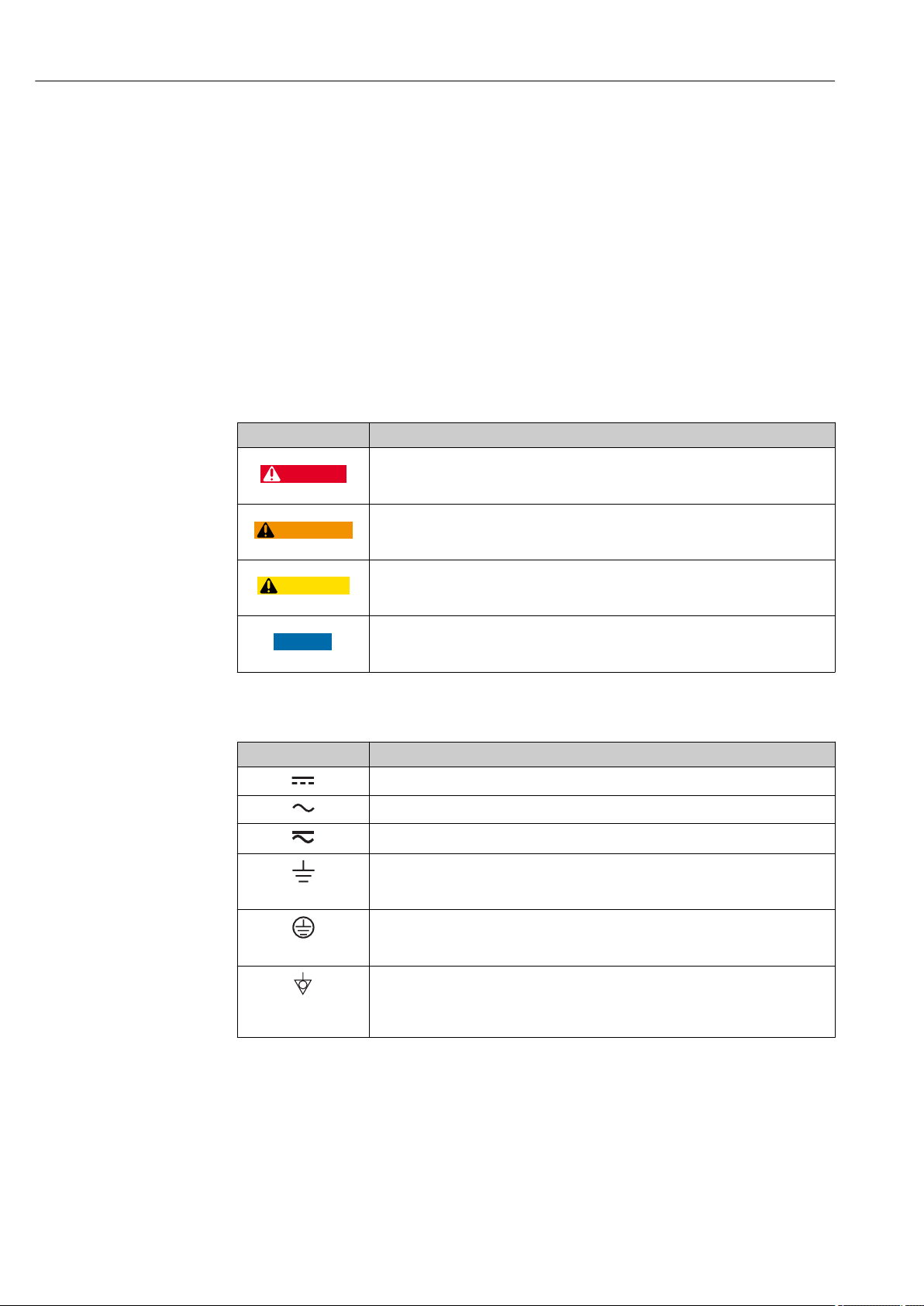
1.2.3 Tool symbols
Symbol Meaning
Torx screwdriver
A0013442
Flat blade screwdriver
A0011220
Cross-head screwdriver
A0011219
Allen key
A0011221
Hexagon wrench
A0011222
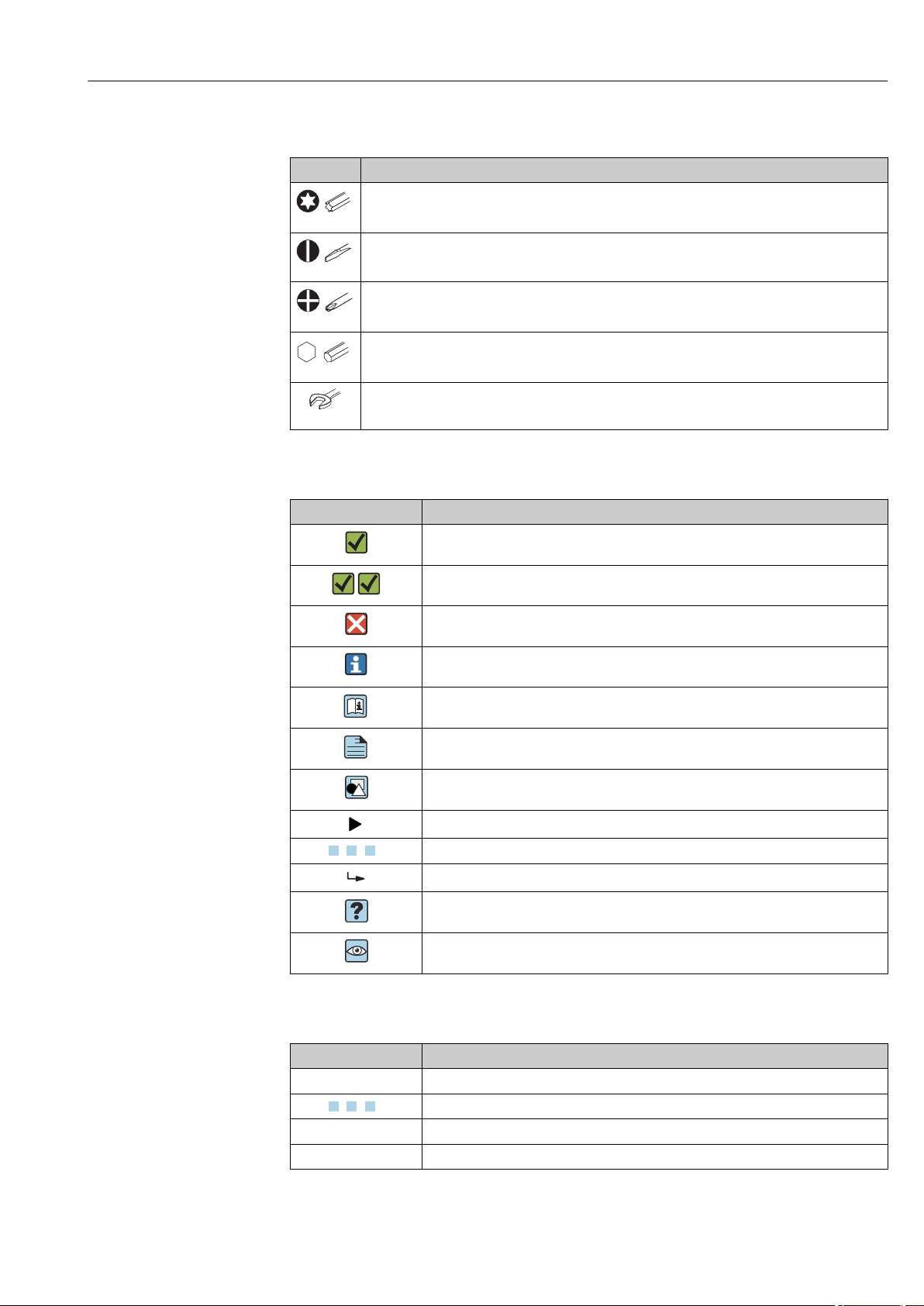
1.2.4 Symbols for certain types of information
Symbol Meaning
Permitted
Procedures, processes or actions that are permitted.
Preferred
Procedures, processes or actions that are preferred.
Forbidden
Procedures, processes or actions that are forbidden.
Tip
Indicates additional information.
Reference to documentation
Reference to page
Reference to graphic
Notice or individual step to be observed
, 2., 3.… Series of steps
Result of a step
Help in the event of a problem
Visual inspection
1.2.5 Symbols in graphics
Symbol Meaning
1, 2, 3 ... Item numbers
, 2., 3.… Series of steps
A, B, C, ... Views
A-A, B-B, C-C, ... Sections
Endress+Hauser 5
Page 6
About this document Micropilot NMR81
-
.
Symbol Meaning
Hazardous area
Indicates a hazardous area.
Safe area (non-hazardous area)
Indicates the non-hazardous area.
1.2.6 Symbols at the device
Symbol Meaning
Safety instructions
Observe the safety instructions contained in the associated Operating Instructions.
Temperature resistance of the connection cables
Specifies the minimum value of the temperature resistance of the connection cables.
6 Endress+Hauser
Page 7
Micropilot NMR81 About this document
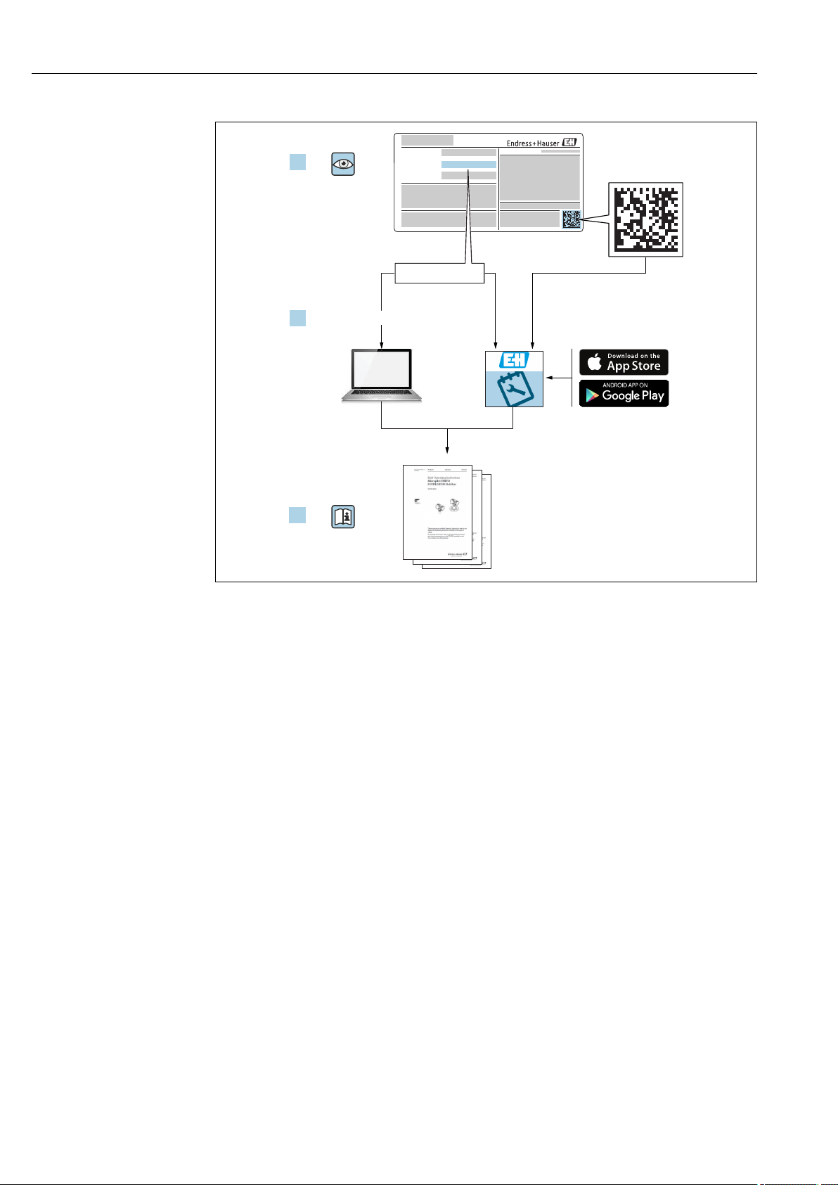
1.3 Documentation
For an overview of the scope of the associated Technical Documentation, refer to the
following:
• The W@M Device Viewer : Enter the serial number from the nameplate
(www.endress.com/deviceviewer)
• The Endress+Hauser Operations App: Enter the serial number from the nameplate
or scan the 2-D matrix code (QR code) on the nameplate.
1.3.1 Technical Information (TI)
The Technical Information contains all the technical data on the device and provides an
overview of the accessories and other products that can be ordered for the device.
Device Technical Information
Micropilot NMR81 TI01252G
1.3.2 Brief Operating Instructions (KA)
The Brief Operating Instructions contain all the essential information from incoming
acceptance to initial commissioning.
Device Brief Operating Instructions
Micropilot NMR81 KA01194G
1.3.3 Operating Instructions (BA)
The Operating Instructions contain all the information that is required in various phases of
the life cycle of the device: from product identification, incoming acceptance and storage,
to mounting, connection, operation and commissioning through to troubleshooting,
maintenance and disposal.
It also contains a detailed explanation of each individual parameter in the operating menu
(except the Expert menu). The description is aimed at those who work with the device
over the entire life cycle and perform specific configurations.
Device Operating Instructions
Micropilot NMR81 BA01450G
1.3.4 Description of Device Parameters (GP)
The Description of Device Parameters provides a detailed explanation of each individual
parameter in the 2nd part of the operating menu: the Expert menu. It contains all the
device parameters and allows direct access to the parameters by entering a specific code.
The description is aimed at those who work with the device over the entire life cycle and
perform specific configurations.
Device Description of Device Parameters
Micropilot NMR81 GP01068G
Endress+Hauser 7
Page 8
About this document Micropilot NMR81
1.3.5 Safety instructions (XA)
Ordering feature 010 "Approval" Meaning XA
BE ATEX II 1/2G Ex ia/db IIC T4 Ga/Gb
ATEX II 2 (1)G Ex db [ia Ga] IIC T4 Gb
FE FM C/US XP-AIS Cl.I Div.1 Gr.BCD T4
AEx d[ia] IIC T4
GE EAC Ga/Gb Ex ia/db IIC T4...T1 X
EAC 1 Ex db [ia] IIC T4...T1 X
IE IEC Ex ia/db IIC T4 Ga/Gb
IEC Ex db [ia Ga] IIC T4 Gb
KE KC Ex ia/db IIC T4 Ga/Gb
KC Ex db [ia Ga] IIC T4 Gb
ME INMETRO Ex ia/db IIC T4 Ga/Gb
INMETRO Ex db [ia Ga] IIC T4 Gb
NE NEPSI Ex ia/db IIC T4 Ga/Gb
NEPSI Ex db [ia Ga] IIC T4 Gb
TA TIIS Ex d[ia] IIC T6 Ga/Gb in preparation
XA01410G
XA01436G
XA01582G
XA01410G
XA01579G
XA01580G
XA01581G
8 Endress+Hauser
Page 9

Micropilot NMR81 About this document
1.4 Registered trademarks
FieldCare
Registered trademark of the Endress+Hauser Process Solutions AG, Reinach, Switzerland
MODBUS
Registered trademark of the MODBUS-IDA, Hopkinton, MA, USA
®
®
Endress+Hauser 9
Page 10

Basic safety instructions Micropilot NMR81
2 Basic safety instructions
2.1 Requirements for the personnel
The personnel for installation, commissioning, diagnostics and maintenance must fulfill
the following requirements:
Trained, qualified specialists must have a relevant qualification for this specific function
‣
and task.
Are authorized by the plant owner/operator.
‣
Are familiar with federal/national regulations.
‣
Before starting work, read and understand the instructions in the manual and
‣
supplementary documentation as well as the certificates (depending on the
application).
Follow instructions and comply with basic conditions.
‣
The operating personnel must fulfill the following requirements:
Are instructed and authorized according to the requirements of the task by the facility's
‣
owner-operator.
Follow the instructions in this manual.
‣
2.2 Designated use
Application and measured materials
The measuring device described in these Operating Instructions is intended for the
continuous, contact-less level measurement of liquids. The device must be installed in
closed metallic tanks or reinforced concrete tanks, or similar enclosure structures made of
comparable attenuating material. Operation is completely harmless to humans and
animals.
Depending on the version ordered, the measuring device can also measure potentially
explosive, flammable, poisonous and oxidizing media.
Measuring devices for use in hazardous areas, in hygienic applications or in applications
where there is an increased risk due to process pressure, are labeled accordingly on the
nameplate.
To ensure that the measuring device remains in proper condition for the operation time:
Only use the measuring device in full compliance with the data on the nameplate and
‣
the general conditions listed in the Operating Instructions and supplementary
documentation.
Check the nameplate to verify if the device ordered can be put to its intended use in the
‣
approval-related area (e.g. explosion protection, pressure vessel safety).
Use the measuring device only for media against which the process-wetted materials
‣
are adequately resistant.
If the measuring device is not operated at atmospheric temperature, compliance with
‣
the relevant basic conditions specified in the associated device documentation is
absolutely essential.
Protect the measuring device permanently against corrosion from environmental
‣
influences.
Observe the limit values in the "Technical Information".
‣
The manufacturer is not liable for damage caused by improper or non-designated use.
Residual risk
During operation the sensor may assume a temperature near the temperature of the
measured material.
Danger of burns due to heated surfaces!
For high process temperatures: Install protection against contact in order to prevent
‣
burns.
10 Endress+Hauser
Page 11

Micropilot NMR81 Basic safety instructions
2.3 Workplace safety
For work on and with the device:
Wear the required personal protective equipment according to federal/national
‣
regulations.
2.4 Operational safety
Risk of injury.
Operate the device in proper technical condition and fail-safe condition only.
‣
The operator is responsible for interference-free operation of the device.
‣
Conversions to the device
Unauthorized modifications to the device are not permitted and can lead to unforeseeable
dangers.
If, despite this, modifications are required, consult with the manufacturer.
‣
Repair
To ensure continued operational safety and reliability,
Carry out repairs on the device only if they are expressly permitted.
‣
Observe federal/national regulations pertaining to repair of an electrical device.
‣
Use original spare parts and accessories from the manufacturer only.
‣
Hazardous area
To eliminate a danger for persons or for the facility when the device is used in the
hazardous area (e.g. explosion protection, pressure vessel safety):
Based on the nameplate, check whether the ordered device is permitted for the
‣
intended use in the hazardous area.
Observe the specifications in the separate supplementary documentation that is an
‣
integral part of these Instructions.
2.5 Product safety
This measuring device is designed in accordance with good engineering practice to meet
state-of-the-art safety requirements, has been tested, and left the factory in a condition in
which it is safe to operate. It meets general safety standards and legal requirements.
2.5.1 CE mark
The measuring system meets the legal requirements of the applicable EC guidelines. These
are listed in the corresponding EC Declaration of Conformity together with the standards
applied.
Endress+Hauser confirms successful testing of the device by affixing to it the CE mark.
Endress+Hauser 11
Page 12
Product description Micropilot NMR81
1 1 1
2 2 2
5 5 5
6
7
8
3
4
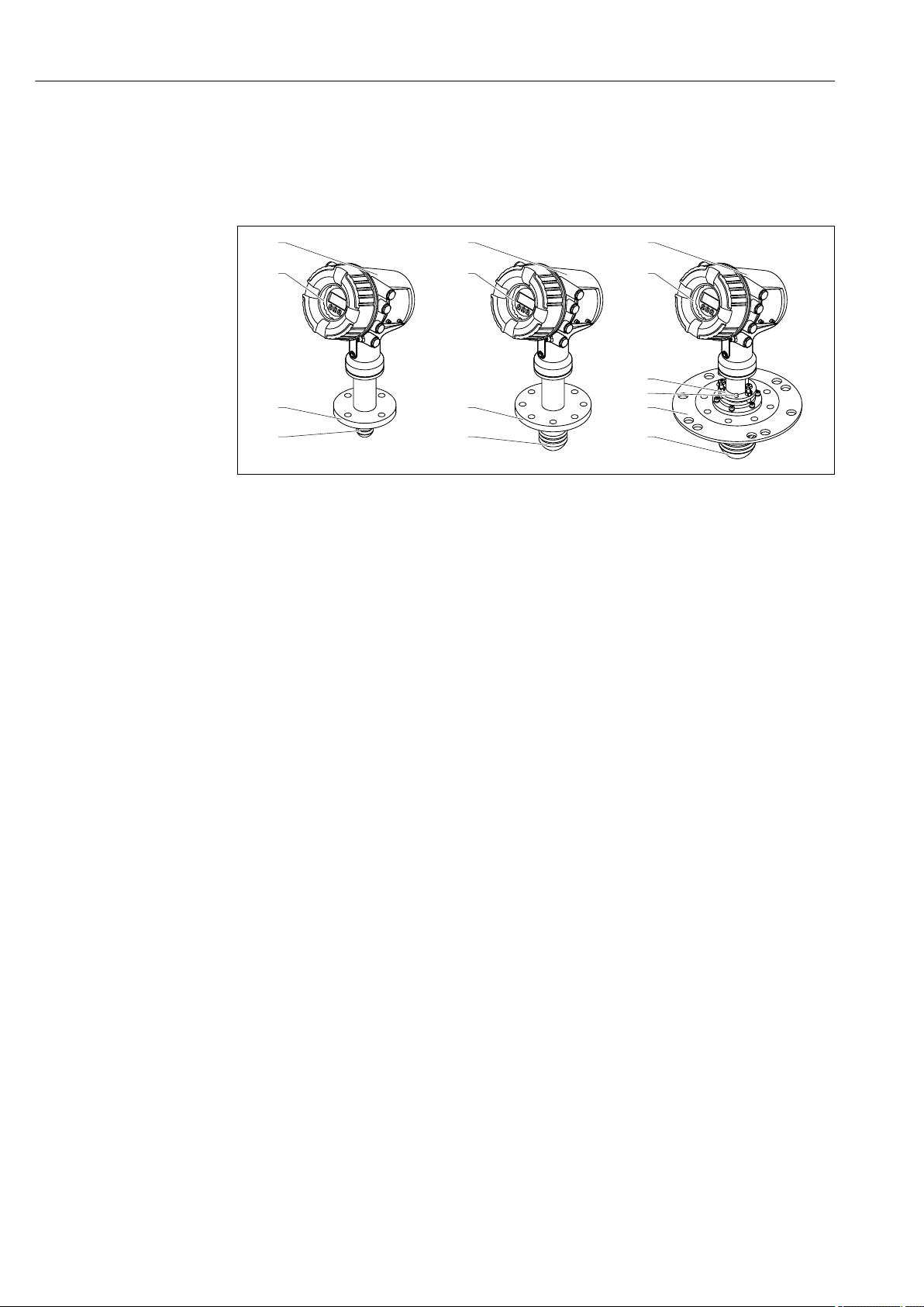
3 Product description
3.1 Product design
A0027765
1 Design of Micropilot NMR81
1 Electronics housing
2 Display and operating module (can be operated without opening the cover)
3 Alignment device for antenna 100 mm (4 in)
4 Level tool (used to check the correct alignment of the antenna)
5 Process connection (flange)
6 Antenna 50 mm (2 in)
7 Antenna 80 mm (3 in)
8 Antenna 100 mm (4 in)
12 Endress+Hauser
Page 13

Micropilot NMR81 Incoming acceptance and product identification
4 Incoming acceptance and product
identification
4.1 Incoming acceptance
Upon receipt of the goods check the following:
• Are the order codes on the delivery note and the product sticker identical?
• Are the goods undamaged?
• Do the nameplate data match the ordering information on the delivery note?
• If required (see nameplate): Are the Safety Instructions (XA) enclosed?
If one of these conditions is not satisfied, contact your Endress+Hauser Sales Center.
4.2 Product identification
The following options are available for identification of the measuring device:
• Nameplate specifications
• Extended order code with breakdown of the device features on the delivery note
• Enter serial numbers from nameplates in W@M Device Viewer
( www.endress.com/deviceviewer ): All information about the measuring device is
displayed.
• Enter the serial number from the nameplates into the Endress+Hauser Operations App
or scan the 2-D matrix code (QR code) on the nameplate with the Endress+Hauser
Operations App: all the information for the measuring device is displayed.
For an overview of the scope of the associated Technical Documentation, refer to the
following:
• The W@M Device Viewer: Enter the serial number from the nameplate
(www.endress.com/deviceviewer)
• The Endress+Hauser Operations App: Enter the serial number from the nameplate or
scan the 2-D matrix code (QR code) on the nameplate.
Endress+Hauser 13
Page 14
Incoming acceptance and product identification Micropilot NMR81
1
3
21
22
23
6
7
8
9
14
16
15
19
20
11
18
12
13
24
25
26
28
27
4
5
Ext. ord. cd.:
Order code:
Ser. no.:
Tp max.:
Mat.:
Date:
FW:
Dev.Rev.:
ex works
DeviceID:
Ta
Ta:
if modification
see sep. label
X =
MWP:
Tank ID:
Tank ref.height:
2
Density range:
Kg/m³
17
10
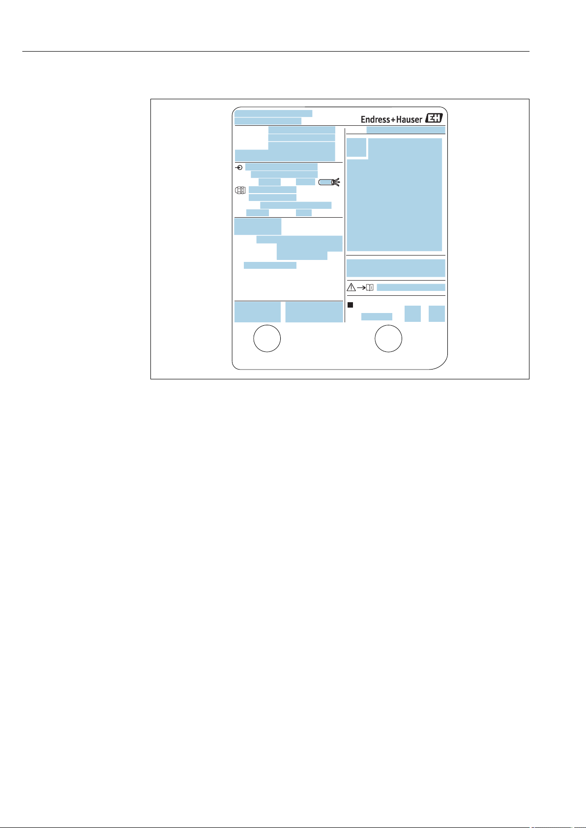
4.2.1 Nameplate
A0027791
2 Nameplate
1 Manufacturer address
2 Device name
3 Order code
4 Serial number
5 Extended order code
6 Supply voltage
7 Maximum process pressure
8 Maximum process temperature
9 Permitted ambient temperature (Ta)
10 Temperature resistance of cable
11 Thread for cable entry
12 Material in contact with process
13 Device ID
14 Firmware version
15 Device revision
16 Metrology certification numbers
17 Customized parametrization data
18 Ambient temperature range
19 CE mark / C-tick mark
20 Additional information on the device version
21 Ingress protection
22 Certificate symbol
23 Data concerning the Ex approval
24 General certificate of approval
25 Associated Safety Instructions (XA)
26 Manufacturing date
27 RoHS mark
28 QR code for the Endress+Hauser Operations App
4.2.2 Manufacturer address
Endress+Hauser SE+Co. KG
Hauptstraße 1
79689 Maulburg, Germany
Address of the manufacturing plant: See nameplate.
14 Endress+Hauser
Page 15

Micropilot NMR81 Incoming acceptance and product identification
4.3 Storage and transport
4.3.1 Storage conditions
• Storage temperature: –50 to +80 °C (–58 to +176 °F)
• Store the device in its original packaging.
4.3.2 Transport
NOTICE
Housing or antenna may be damaged or break away.
Risk of injury
Transport the measuring device to the measuring point in its original packaging or at
‣
the process connection.
Do not fasten lifting devices (hoisting slings, lifting eyes etc.) at the housing or the
‣
antenna but at the process connection. Take into account the mass center of the device
in order to avoid unintended tilting.
Comply with the safety instructions, transport conditions for devices over 18kg
‣
(39.6lbs) (IEC61010).
Endress+Hauser 15
Page 16
Installation Micropilot NMR81
H
max
øD
5 Installation
5.1 Installation conditions
5.1.1 Mounting position
General conditions
• Do not install in the centre of the tank.
• Do not install above a filling stream.
• Avoid any tank installations (e.g. limit switches, temperature probes) within in the
signal beam.
Minimum wall distance
Measuring range Minimum wall distance
Antenna 50mm/2"
5 m (16 ft) 0.3 m (0.98 ft) 0.17 m (0.55 ft) 0.13 m (0.44 ft)
10 m (33 ft) 0.6 m (1.9 ft) 0.33 m (1.1 ft) 0.27 m (0.87 ft)
15 m (49 ft) 0.9 m (2.9 ft) 0.5 m (1.6 ft) 0.4 m (1.3 ft)
20 m (66 ft) 1.2 m (3.9 ft) 0.67 m (2.2 ft) 0.53 m (1.7 ft)
25 m (82 ft) 1.5 m (4.9 ft) 0.83 m (2.7 ft) 0.67 m (2.2 ft)
30 m (98 ft) 1.8 m (5.9 ft) 1.0 m (3.3 ft) 0.8 m (2.6 ft)
1)
Antenna 80mm/3"
2)
Antenna 100mm/4"
3)
1) Ordering feature 100 "Antenna", option AB
2) Ordering feature 100 "Antenna", option AC
3) Ordering feature 100 "Antenna", option AD
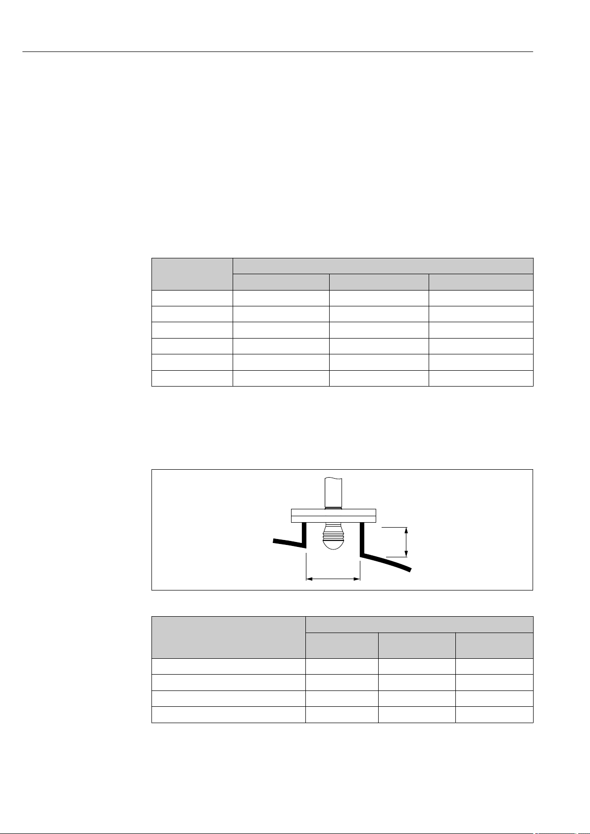
5.1.2 Mounting nozzle
Inner nozzle diameter (ØD) Maximum nozzle length (H
Antenna AB
50mm/2"
> 45 mm (1.77 in); ≤ 75 mm (2.95 in) 600 mm (24 in) - -
> 75 mm (2.95 in); ≤ 95 mm (3.74 in) 1 000 mm (40 in) 1 700 mm (68 in) -
> 95 mm (3.74 in); ≤ 150 mm (5.91 in) 1 250 mm (50 in) 2 150 mm (86 in) 2 850 mm (114 in)
> 150 mm (5.91 in) 1 850 mm (74 in) 3 200 mm (128 in) 4 300 mm (172 in)
2)
:
Antenna AC
80mm/3"
2)
:
1)
)
max
Antenna AD
100mm/4"
2)
A0032956
:
1) In case of longer nozzles, a reduced measuring performance is to be expected.
2) Feature 100 of the product structure
16 Endress+Hauser
Page 17
Micropilot NMR81 Installation
h
2
3
1
4°
øD
ød
h
max
h
min
±8
°
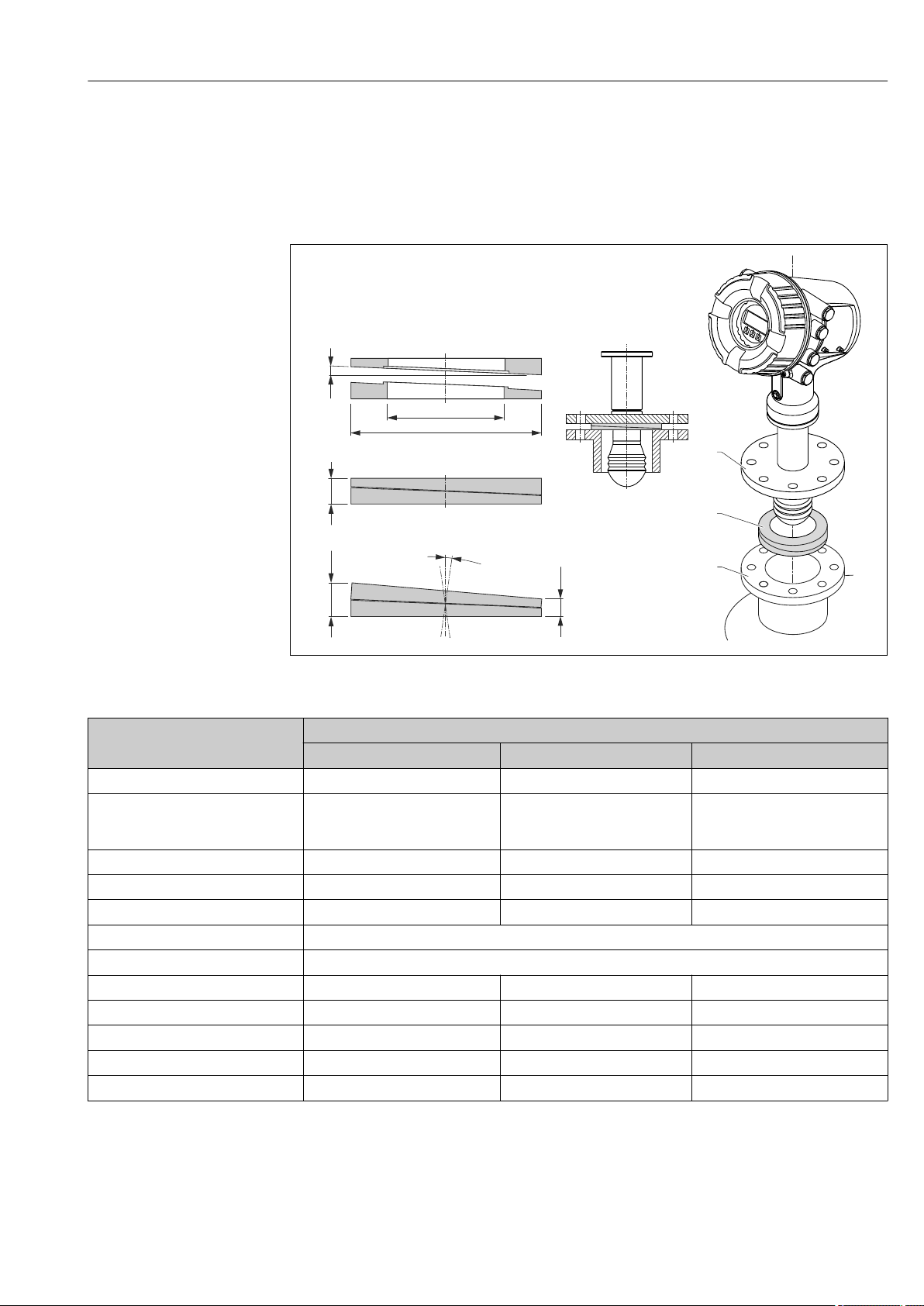
5.1.3 Vertical alignment of the 50mm(2") and 80mm (3") antenna
For optimum measuring accuracy the antenna must be installed at right angles to the
medium surface. An adjustable seal is available for the alignment.
Adjustable seal
A0027787
3 Adjustable seal used to align the device by ±8 °
Property Ordering feature 620 "Accessory Enclosed"
PS PT PU
Order code
Compatible with • DN50 PN10-40
Length of screws 100 mm (3.9 in) 100 mm (3.9 in) 100 mm (3.9 in)
Size of screws M14 M14 M14
Process pressure –0.1 to +0.1 bar (–1.45 to +1.45 psi)
Process temperature –40 to +80 °C (–40 to +176 °F)
1) With this ordering feature the adjustable seal is supplied together with the device.
2) This order code must be used if the adjustable seal is ordered separately.
2)
• ASME 2" 150lbs
• JIS 50A 10K
Material FKM FKM FKM
ØD 105 mm (4.13 in) 142 mm (5.59 in) 133 mm (5.24 in)
Ød 60 mm (2.36 in) 89 mm (3.5 in) 89 mm (3.5 in)
h 16.5 mm (0.65 in) 22 mm (0.87 in) 22 mm (0.87 in)
h
min
h
max
71285499 71285501 71285503
DN80 PM10-40 • ASME 3" 150lbs
9 mm (0.35 in) 14 mm (0.55 in) 14 mm (0.55 in)
24 mm (0.95 in) 30 mm (1.18 in) 30 mm (1.18 in)
1)
• JIS 80A 10K
Endress+Hauser 17
Page 18
Installation Micropilot NMR81
α
90 °
1
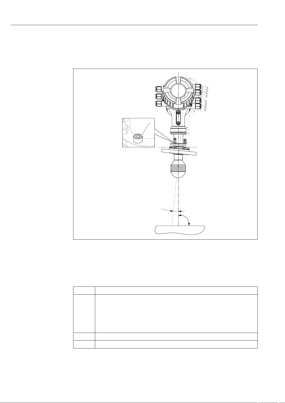
5.1.4 Vertical alignment of the 100mm(4") antenna
For optimum measuring accuracy the antenna must be installed at right angles to the
medium surface. For this purpose the 100mm(4") antenna always has an alignment unit.
A level tool indicating the correct alignment is attached to the alignment tool.
A0027776
4 Alignment unit of the 100mm(4") antenna
1 Level tool indicating the correct alignment
α Alignment angle; α
max
= 25 °
5.2 Post-installation check
Is the device undamaged (visual inspection)?
m
Does the device conform to the measuring point specifications?
For example:
• Process temperature
m
• Process pressure (refer to the chapter on "Material load curves" of the "Technical Information"
document)
• Ambient temperature range
• Measuring range
Are the measuring point identification and labeling correct (visual inspection)?
m
Is the device adequately protected from precipitation and direct sunlight?
m
18 Endress+Hauser
Page 19
Micropilot NMR81 Electrical connection
D
E
F
C
B
A
1
1
1
1 3
2
2 4
1
HR
CDI
WP
on
SIM
22334
4
112233445566778
8
i
D
E
F
C
B
A
1
1
1
1 3
2
2 4
1
HR
CDI
WP
on
SIM
22334
4
112233445566778
8
i
G
1
3
2
POWER
G
1
3
2
POWER
G1 N
G3 L
AC 85...264 V
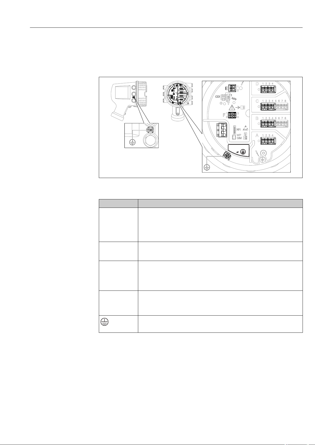
6 Electrical connection
6.1 Terminal assignment
5 Terminal compartment (typical example) and ground terminals
Terminal area Module
Up to four I/O modules, depending on the order code
A/B/C/D
(slots for I/O
modules)
• Modules with four terminals can be in any of these slots.
• Modules with eight terminals can be in slot B or C.
The exact assignment of the modules to the slots is dependent on the device version
→ 22.
E HART Ex i/IS interface
• E1: H+
• E2: H-
F Remote display
• F1: VCC (connect to terminal 81 of the remote display)
• F2: Signal B (connect to terminal 84 of the remote display)
• F3: Signal A (connec t to terminal 83 of the remote display)
• F4: Gnd (connect to terminal 82 of the remote display)
Power supply: 85 to 264 V
G
• G1: N
• G2: not connected
AC
• G3: L
Protective ground connection (M4 screw)
A0018339
A0026372
Endress+Hauser 19
Page 20
Electrical connection Micropilot NMR81
D
E
F
C
B
A
1
1
1
1 3
2
2 4
1
HR
CDI
WP
on
SIM
22334
4
112233445566778
8
i
G
1
3
2
POWER
4
F
1
1 3
2
2 4
HR
CDI
WP
SIM
G
1
3
2
POWER
1
3
Vcc
Gnd
A B
2
D
E
F
C
B
A
1
1
1
1 3
2
2 4
1
HR
CDI
WP
on
SIM
22334
4
112233445566778
8
i
G
1
3
2
POWER
F
1 3
2 4
HR
WP
Vcc
Gnd
A
B
81 82 83 84
F1 F2 F3 F4
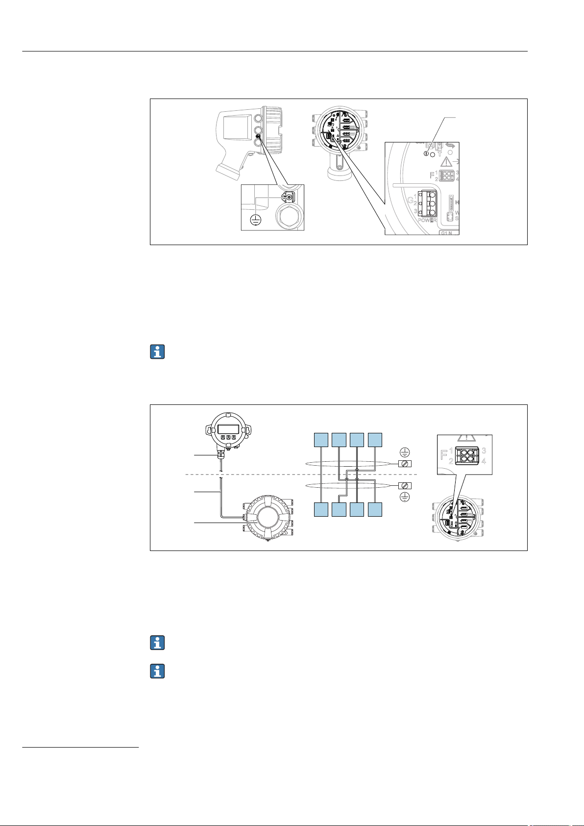
6.1.1 Power supply
A0033413
G1 N
G2 not connected
G3 L
4 Green LED: indicates power supply
Supply voltage
85 to 264 VAC, 50/60 Hz, 28.8 VA
1)
The supply voltage is also indicated on the nameplate.
6.1.2 Remote display and operating module DKX001
6 Connection of the remote display and operating module DKX001 to the Tank Gauging device (NMR8x,
NMS8x or NRF8x)
1 Remote display and operating module
2 Connecting cable
3 Tank Gauging device (NMR8x, NMS8x or NRF8x)
A0037025
The remote display and operating module DKX001 is available as an accessory. For
details refer to SD01763D.
• The measured value is indicated on the DKX001 and on the local display and
operating module simulataneously.
• The operating menu cannot be accessed on both modules at the same time. If the
1) maximum value; actual value depending on modules installed. 28.8 VA includes the nominal power, and the cabling specification has to meet
this value. On the other hand, the effective power consumption is 12 W.
20 Endress+Hauser
operating menu is entered in one of these modules, the other module is
automatically locked. This locking remains active until the menu is closed in the
first module (back to measured value display).
Page 21
Micropilot NMR81 Electrical connection
D
E
F
C
B
A
1
1
1
1 3
2
2 4
1
HR
CDI
WP
on
SIM
22334
4
112233445566778
8
i
E
1
1
2
CDI
i
G
1
3
2
POWER
3
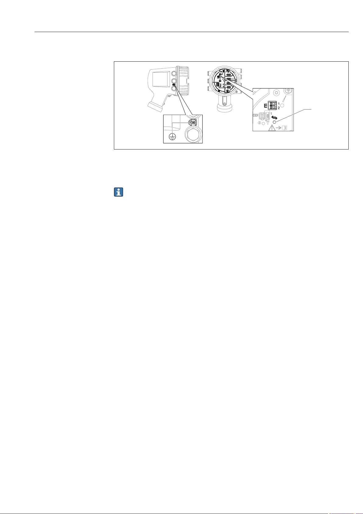
6.1.3 HART Ex i/IS interface
A0033414
E1 H+
E2 H3 Orange LED: indicates data communication
This interface always operates as the main HART master for connected HART slave
transmitters. The Analog I/O modules, on the other hand, can be configured as a
HART master or slave → 29 → 31.
Endress+Hauser 21
Page 22
Electrical connection Micropilot NMR81
Spare parts for: Proservo NMS81
Ser.-no.:
8A21AC098AF4
Spare part
Spare no./structure
Displacer
Wire Drum
Additional information:
XPF0002-AABICR+
AAEAEBEFLALC76
XPF0002-AABEFEG+
XPF0002-AABEFEG+
XPF0002-AABEFEG+
XPF0002-AABEFEG+
XPF0002-AABEFEG+
XPF0002-AABEFEG+
XPF0002-AABEFEG+
XPF0002-AABEFEG+
71273689
7122xxxx
XPF0002-AABEFEG+
AAAAACDEFEG+
XPF0002-AAACABADJ+
AAHAHCHRIJJAJBKP
71023451
71023451
71023451
Cover
IOM-V1
IOM-A/RTD
IOM-D
SlotA
Slot B
Slot C
Slot D
IO Mod FF
Display
Display asm.
Detector
Main electr.
SMS electr.
6
7
8
9
10
11
12
5
4
3
2
1
www.endress.com/deviceviewer
1
D
C
B
A
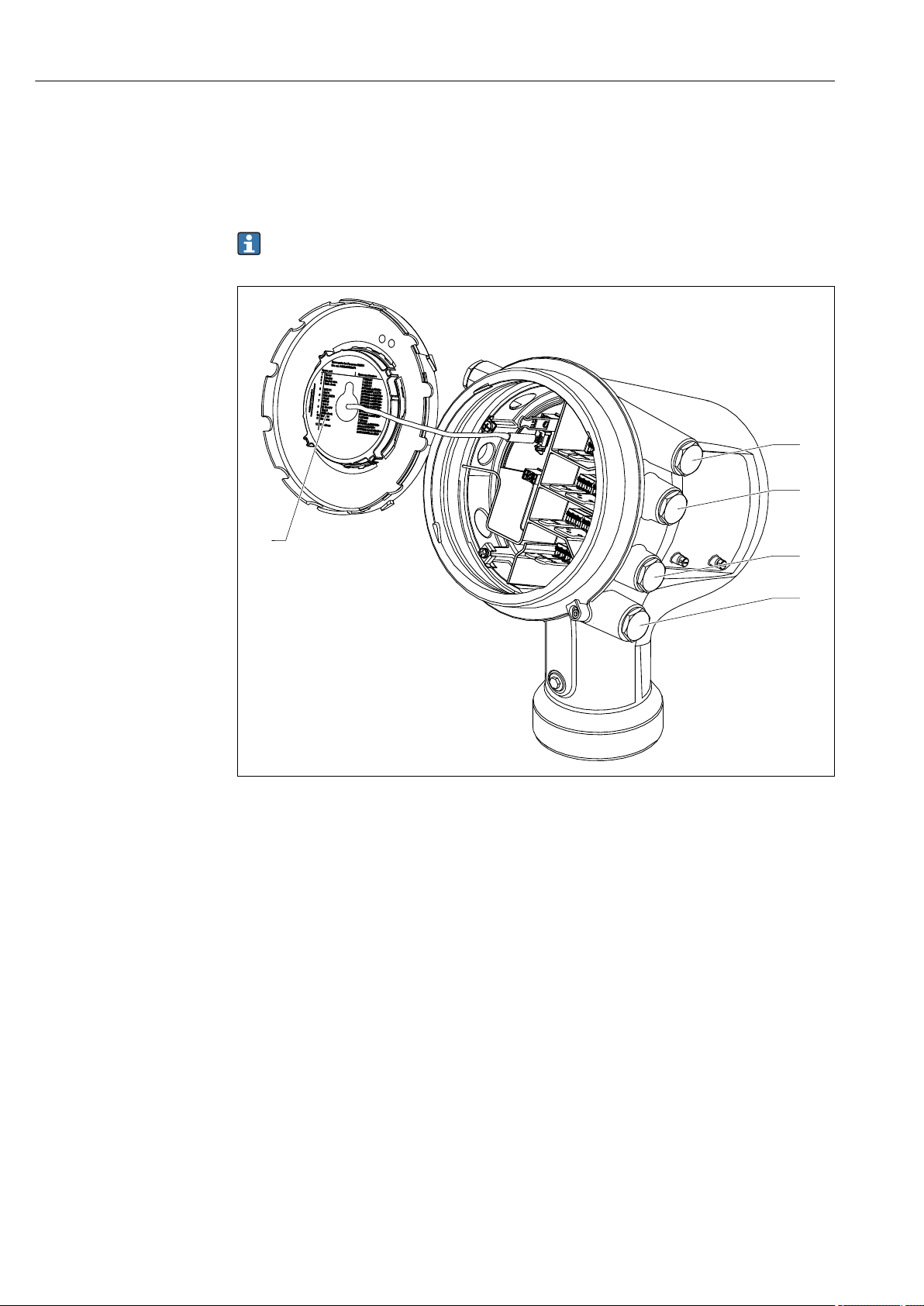
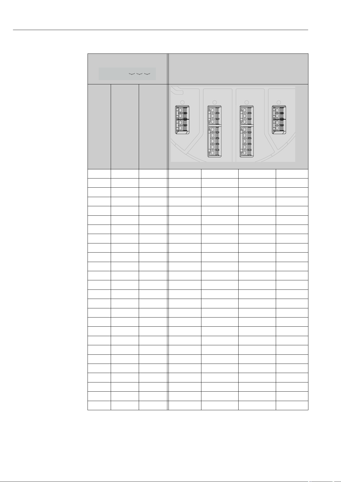
6.1.4 Slots for I/O modules
The terminal compartment contains four slots (A, B, C and D) for I/O modules. Depending
on the device version (ordering features 040, 050 and 060) these slots contain different
I/O modules. The table below shows which module is located in which slot for a specific
device version.
The slot assignment for the device is also indicated on a label attached to the back
cover of the display module.
A0030070
1 Label showing (among other things) the modules in the slots A to D.
A Cable entry for slot A
B Cable entry for slot B
C Cable entry for slot C
D Cable entry for slot D
22 Endress+Hauser
Page 23

Micropilot NMR81 Electrical connection
NMx8x - XX XX XXxxxx ...
060050040
D
C
B
A
1
1
2
2
3
3
4
4
1
1
2
2
3
3
4
4
5
5
6
6
7
7
8
8
"Primary Output" (040) = "Modbus" (A1)
Ordering feature
040
Primary
Output
A1 X0 X0 Modbus - - -
A1 X0 A1 Modbus - - Digital
A1 X0 A2 Modbus - Digital Digital
A1 X0 A3 Modbus Digital Digital Digital
A1 X0 B1 Modbus Modbus - -
A1 X0 B2 Modbus Modbus - Digital
A1 X0 B3 Modbus Modbus Digital Digital
A1 A1 X0 Modbus Analog Ex d/XP - -
A1 A1 A1 Modbus Analog Ex d/XP - Digital
A1 A1 A2 Modbus Analog Ex d/XP Digital Digital
A1 A1 B1 Modbus Modbus Analog Ex d/XP -
A1 A1 B2 Modbus Modbus Analog Ex d/XP Digital
A1 A2 X0 Modbus Analog Ex d/XP Analog Ex d/XP -
A1 A2 A1 Modbus Analog Ex d/XP Analog Ex d/XP Digital
A1 A2 B1 Modbus Analog Ex d/XP Analog Ex d/XP Modbus
A1 B1 X0 Modbus Analog Ex i/IS - -
A1 B1 A1 Modbus Analog Ex i/IS - Digital
A1 B1 A2 Modbus Analog Ex i/IS Digital Digital
A1 B1 B1 Modbus Modbus Analog Ex i/IS -
A1 B1 B2 Modbus Modbus Analog Ex i/IS Digital
A1 B2 X0 Modbus Analog Ex i/IS Analog Ex i/IS -
A1 B2 A1 Modbus Analog Ex i/IS Analog Ex i/IS Digital
A1 B2 B1 Modbus Analog Ex i/IS Analog Ex i/IS Modbus
A1 C2 X0 Modbus Analog Ex i/IS Analog Ex d/XP -
A1 C2 A1 Modbus Analog Ex i/IS Analog Ex d/XP Digital
A1 C2 B1 Modbus Analog Ex i/IS Analog Ex d/XP Modbus
050
Secondary
IO Analog
060
Secondary
IO Digital
Ex d/XP
Terminal area
A0023888
Endress+Hauser 23
Page 24
Electrical connection Micropilot NMR81
NMx8x - XX XX XXxxxx ...
060050040
D
C
B
A
1
1
2
2
3
3
4
4
1
1
2
2
3
3
4
4
5
5
6
6
7
7
8
8
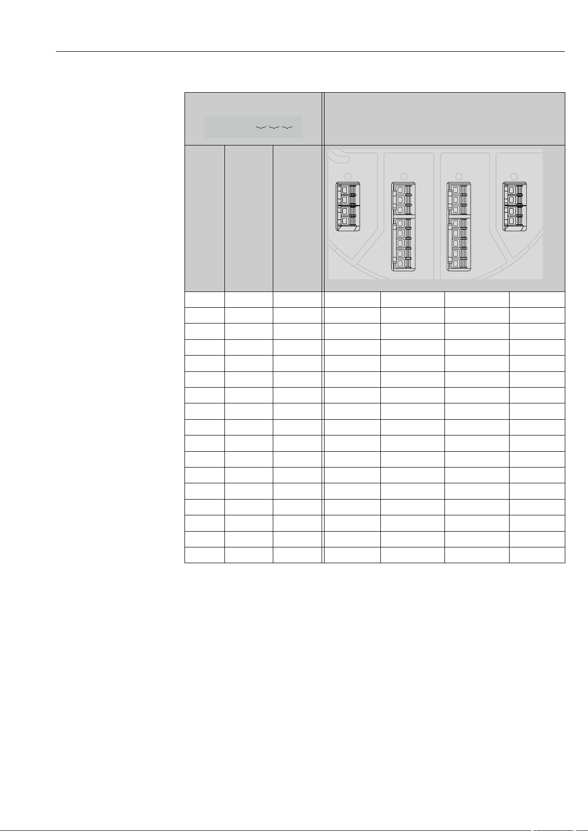
"Primary Output" (040) = "V1" (B1)
Ordering feature
040
Primary
Output
B1 X0 X0 V1 - - -
B1 X0 A1 V1 - - Digital
B1 X0 A2 V1 - Digital Digital
B1 X0 A3 V1 Digital Digital Digital
B1 X0 B1 V1 Modbus - -
B1 X0 B2 V1 Modbus - Digital
B1 X0 B3 V1 Modbus Digital Digital
B1 A1 X0 V1 Analog Ex d/XP - -
B1 A1 A1 V1 Analog Ex d/XP - Digital
B1 A1 A2 V1 Analog Ex d/XP Digital Digital
B1 A1 B1 V1 Modbus Analog Ex d/XP -
B1 A1 B2 V1 Modbus Analog Ex d/XP Digital
B1 A2 X0 V1 Analog Ex d/XP Analog Ex d/XP -
B1 A2 A1 V1 Analog Ex d/XP Analog Ex d/XP Digital
B1 A2 B1 V1 Analog Ex d/XP Analog Ex d/XP Modbus
B1 B1 X0 V1 Analog Ex i/IS - -
B1 B1 A1 V1 Analog Ex i/IS - Digital
B1 B1 A2 V1 Analog Ex i/IS Digital Digital
B1 B1 B1 V1 Modbus Analog Ex i/IS -
B1 B1 B2 V1 Modbus Analog Ex i/IS Digital
B1 B2 X0 V1 Analog Ex i/IS Analog Ex i/IS -
B1 B2 A1 V1 Analog Ex i/IS Analog Ex i/IS Digital
B1 B2 B1 V1 Analog Ex i/IS Analog Ex i/IS Modbus
B1 C2 X0 V1 Analog Ex i/IS Analog Ex d/XP -
B1 C2 A1 V1 Analog Ex i/IS Analog Ex d/XP Digital
B1 C2 B1 V1 Analog Ex i/IS Analog Ex d/XP Modbus
050
Secondary
IO Analog
060
Secondary
IO Digital
Ex d/XP
Terminal area
A0023888
24 Endress+Hauser
Page 25
Micropilot NMR81 Electrical connection
NMx8x - XX XX XXxxxx ...
060050040
D
C
B
A
1
1
2
2
3
3
4
4
1
1
2
2
3
3
4
4
5
5
6
6
7
7
8
8
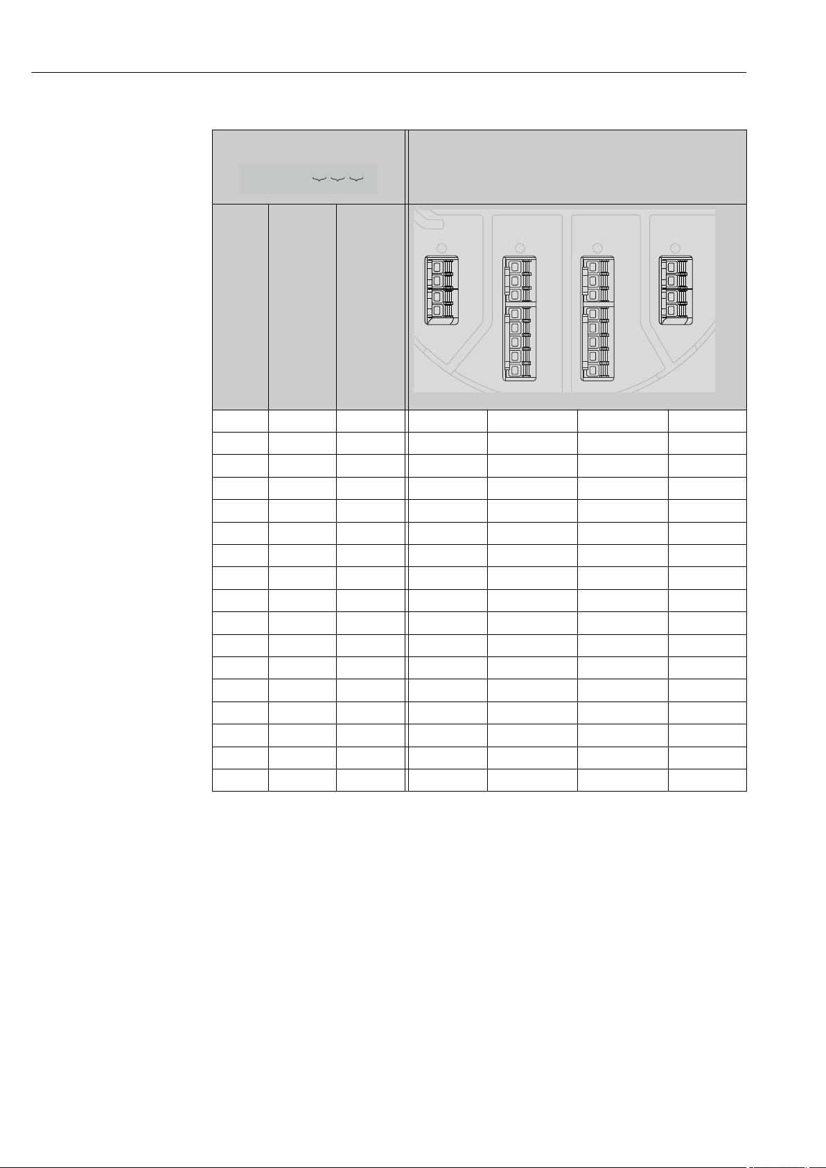
"Primary Output" (040) = "4-20mA HART Ex d" (E1)
Ordering feature
040
Primary
Output
E1 X0 X0 - Analog Ex d/XP - -
E1 X0 A1 - Analog Ex d/XP - Digital
E1 X0 A2 - Analog Ex d/XP Digital Digital
E1 X0 A3 Digital Analog Ex d/XP Digital Digital
E1 X0 B1 Modbus Analog Ex d/XP - -
E1 X0 B2 Modbus Analog Ex d/XP - Digital
E1 X0 B3 Modbus Analog Ex d/XP Digital Digital
E1 A1 X0 - Analog Ex d/XP Analog Ex d/XP -
E1 A1 A1 - Analog Ex d/XP Analog Ex d/XP Digital
E1 A1 A2 Digital Analog Ex d/XP Analog Ex d/XP Digital
E1 A1 B1 Modbus Analog Ex d/XP Analog Ex d/XP -
E1 A1 B2 Modbus Analog Ex d/XP Analog Ex d/XP Digital
E1 B1 X0 - Analog Ex d/XP Analog Ex i/IS -
E1 B1 A1 - Analog Ex d/XP Analog Ex i/IS Digital
E1 B1 A2 Digital Analog Ex d/XP Analog Ex i/IS Digital
E1 B1 B1 Modbus Analog Ex d/XP Analog Ex i/IS -
E1 B1 B2 Modbus Analog Ex d/XP Analog Ex i/IS Digital
050
Secondary
IO Analog
060
Secondary
IO Digital
Ex d/XP
Terminal area
A0023888
Endress+Hauser 25
Page 26
Electrical connection Micropilot NMR81
NMx8x - XX XX XXxxxx ...
060050040
D
C
B
A
1
1
2
2
3
3
4
4
1
1
2
2
3
3
4
4
5
5
6
6
7
7
8
8
"Primary Output" (040) = "4-20mA HART Ex i" (H1)
Ordering feature
040
Primary
Output
H1 X0 X0 - Analog Ex i/IS - -
H1 X0 A1 - Analog Ex i/IS - Digital
H1 X0 A2 - Analog Ex i/IS Digital Digital
H1 X0 A3 Digital Analog Ex i/IS Digital Digital
H1 X0 B1 Modbus Analog Ex i/IS - -
H1 X0 B2 Modbus Analog Ex i/IS - Digital
H1 X0 B3 Modbus Analog Ex i/IS Digital Digital
H1 A1 X0 - Analog Ex i/IS Analog Ex d/XP -
H1 A1 A1 - Analog Ex i/IS Analog Ex d/XP Digital
H1 A1 A2 Digital Analog Ex i/IS Analog Ex d/XP Digital
H1 A1 B1 Modbus Analog Ex i/IS Analog Ex d/XP -
H1 A1 B2 Modbus Analog Ex i/IS Analog Ex d/XP Digital
H1 B1 X0 - Analog Ex i/IS Analog Ex i/IS -
H1 B1 A1 - Analog Ex i/IS Analog Ex i/IS Digital
H1 B1 A2 Digital Analog Ex i/IS Analog Ex i/IS Digital
H1 B1 B1 Modbus Analog Ex i/IS Analog Ex i/IS -
H1 B1 B2 Modbus Analog Ex i/IS Analog Ex i/IS Digital
050
Secondary
IO Analog
060
Secondary
IO Digital
Ex d/XP
Terminal area
A0023888
26 Endress+Hauser
Page 27
Micropilot NMR81 Electrical connection
D
E
F
C
B
A
1
1
1
1 3
2
2 4
1
HR
WP
on
SIM
2
23344
112233445566778
8
A
1 2 3 4
A1-4
i
D
1
2 3 4
D1-4
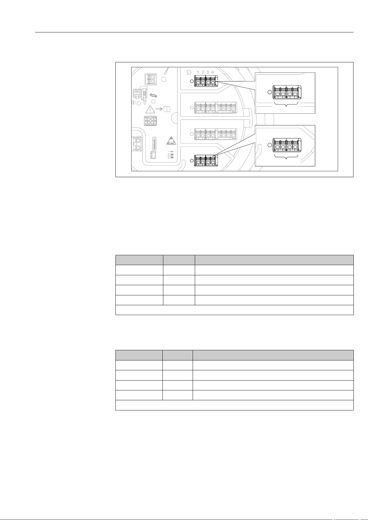
6.1.5 Terminals of the "Modbus" or "V1" module
A0031200
7 Designation of the "Modbus" or "V1" modules (examples); depending on the device version these modules
may also be in slot B or C.
Depending on the device version, the "Modbus" and/or "V1" module may be in different
slots of the terminal compartment. In the operating menu the "Modbus" and "V1" interfaces
are designated by the respective slot and the terminals within this slot: A1-4, B1-4, C1-4,
D1-4.
Terminals of the "Modbus" module
Terminal
X1 S Cable shielding connected via a capacitor to EARTH
X2 0V Common reference
X3 B- Non-inverting signal line
X4 A+ Inverting signal line
Designation of the module in the operating menu: Modbus X1-4; (X = A, B, C or D)
1) In this column, "X" stands for one of the slots "A", "B", "C", or "D".
1)
Name Description
Terminals of the "V1" module
Terminal
X1 S Cable shielding connected via capacitor to EARTH
X2 not connected
X3 B- Protocol loop signal -
X4 A+ Protocol loop signal +
Designation of the module in the operating menu: V1 X1-4; (X = A, B, C or D)
1)
Name Description
Endress+Hauser 27
1) In this column, "X" stands for one of the slots "A", "B", "C", or "D".
Page 28
Electrical connection Micropilot NMR81
D
E
F
C
B
A
1
1
1
1 3
2
2 4
1
HR
WP
on
SIM
22334
4
112233445566778
8
i
B
1 2 3 4 5 6 7 8
B1-3 B4-8
C
1 2 3 4 5 6 7 8
C1-3 C4-8
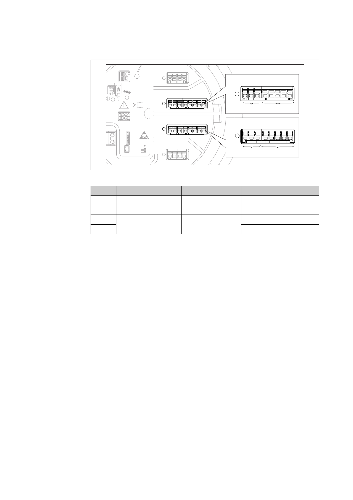
6.1.6 Terminals of the "Analog I/O" module (Ex d /XP or Ex i/IS)
A0031168
Terminals Function Connection diagrams Designation in the operating menu
B1-3 Analog input or output
C1-3 Analog I/O C1-3 (→ 142)
B4-8 Analog input RTD: → 32 Analog IP B4-8 (→ 136)
C4-8 Analog IP C4-8 (→ 136)
(configurable)
• Passive usage: → 29
• Active usage: → 31
Analog I/O B1-3 (→ 142)
28 Endress+Hauser
Page 29
Micropilot NMR81 Electrical connection
D
E
F
C
B
A
1
1
1
1 3
2
2 4
1
HR
CDI
WP
on
SIM
22334
4
112233445566778
8
i
G
1
3
2
POWER
ca
b
-
+
!
E
G
F
1
1
1 3
2
2 4
HR
CDI
WP
on
SIM
i
D
C
B
A
1122334
4
112233445566778
8
G
1
3
2
POWER
D
E
F
C
B
A
1
1
1
1 3
2
2 4
1
HR
CDI
WP
on
SIM
22334
4
112233445566778
8
i
G
1
3
2
POWER
a
+
–
E
G
F
1
1
1 3
2
2 4
HR
CDI
WP
on
SIM
i
D
C
B
A
1122334
4
112233445566778
8
G
1
3
2
POWER
b
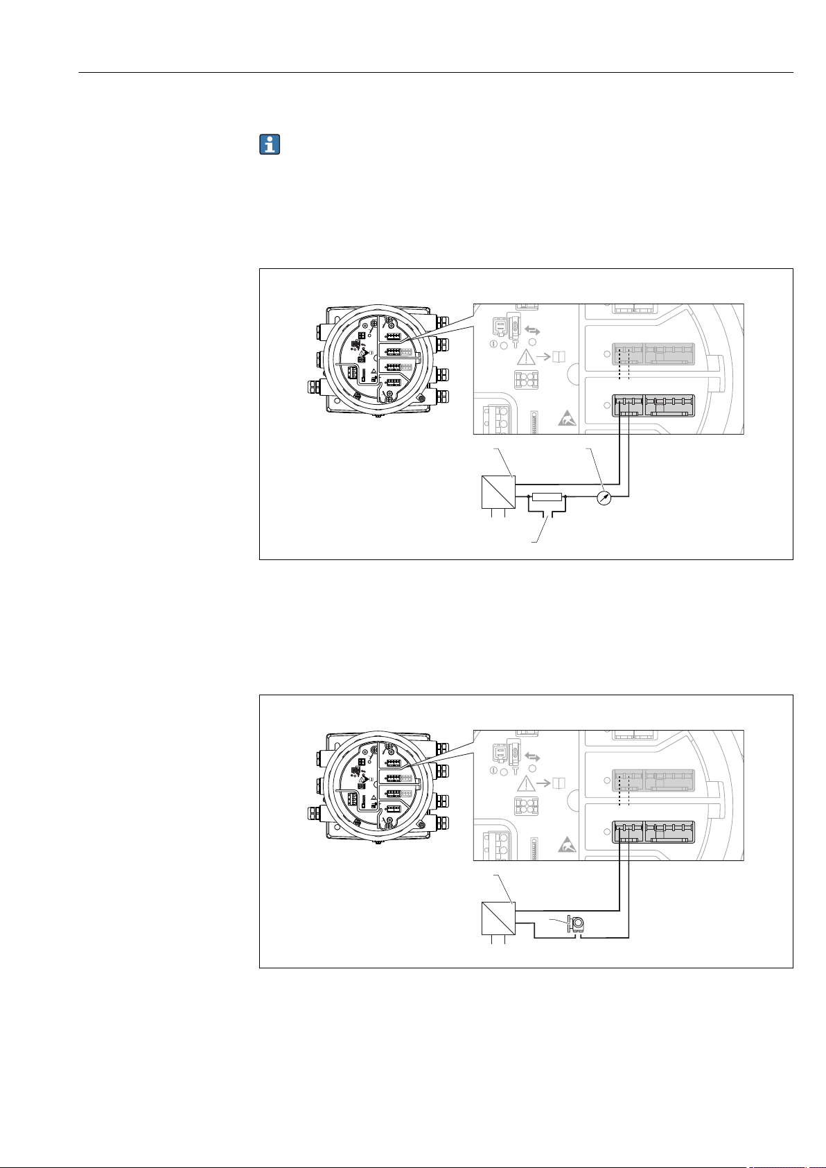
6.1.7 Connection of the "Analog I/O" module for passive usage
• In the passive usage the supply voltage for the communication line must be supplied
by an external source.
• The wiring must be in accordance with the intended operating mode of the Analog
I/O module; see the drawings below.
• Screened cable must be used for the 4...20mA signal line.
"Operating mode" = "4..20mA output" or "HART slave +4..20mA output"
A0027931
8 Passive usage of the Analog I/O module in the output mode
a Power supply
b HART signal output
c Analog signal evaluation
"Operating mode" = "4..20mA input" or "HART master+4..20mA input"
Endress+Hauser 29
9 Passive usage of the Analog I/O module in the input mode
a Power supply
b External device with 4...20mA and/or HART signal output
A0027933
Page 30
Electrical connection Micropilot NMR81
D
E
F
C
B
A
1
1
1
1 3
2
2 4
1
HR
CDI
WP
on
SIM
22334
4
112233445566778
8
i
G
1
3
2
POWER
a
+
–
!
E
G
F
1
1
1 3
2
2 4
HR
CDI
WP
on
SIM
i
D
C
B
A
1122334
4
112233445566778
8
G
1
3
2
POWER
b
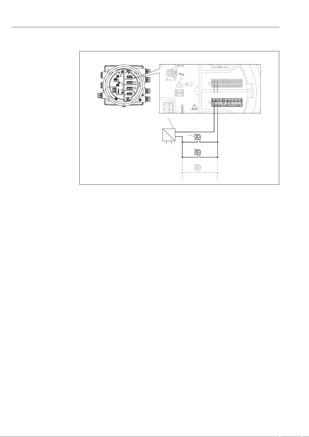
"Operating mode" = "HART master"
A0027934
10 Passive usage of the Analog I/O module in the HART master mode
a Power supply
b Up to 6 external devices with HART signal output
30 Endress+Hauser
Page 31

Micropilot NMR81 Electrical connection
D
E
F
C
B
A
1
1
1
1 3
2
2 4
1
HR
CDI
WP
on
SIM
22334
4
112233445566778
8
i
G
1
3
2
POWER
b
a
-
+
E
G
F
1
1
1 3
2
2 4
HR
CDI
WP
on
SIM
i
D
C
B
A
1122334
4
112233445566778
8
G
1
3
2
POWER
D
E
F
C
B
A
1
1
1
1 3
2
2 4
1
HR
CDI
WP
on
SIM
22334
4
112233445566778
8
i
G
1
3
2
POWER
E
G
F
1
1
1 3
2
2 4
HR
CDI
WP
on
SIM
i
D
C
B
A
1122334
4
112233445566778
8
G
1
3
2
POWER
-
+
a
6.1.8 Connection of the "Analog I/O" module for active usage
• In the active usage the supply voltage for the communication line is supplied by the
device itself. There is no need of an external power supply.
• The wiring must be in accordance with the intended operating mode of the Analog
I/O module; see the drawings below.
• Screened cable must be used for the 4...20mA signal line.
• Maximum current consumption of the connected HART devices: 24 mA
(i.e. 4 mA per device if 6 devices are connected).
• Output voltage of the Ex-d module: 17.0 V@4 mA to 10.5 V@22 mA
• Output voltage of the Ex-ia module: 18.5 V@4 mA to 12.5 V@22 mA
"Operating mode" = "4..20mA output" or "HART slave +4..20mA output"
A0027932
11 Active usage of the Analog I/O module in the output mode
a HART signal output
b Analog signal evaluation
"Operating mode" = "4..20mA input" or "HART master+4..20mA input"
Endress+Hauser 31
12 Active usage of the Analog I/O module in the input mode
a External device with 4...20mA and/or HART signal output
A0027935
Page 32

Electrical connection Micropilot NMR81
D
E
F
C
B
A
1
1
1
1 3
2
2 4
1
HR
CDI
WP
on
SIM
22334
4
112233445566778
8
i
G
1
3
2
POWER
E
G
F
1
1
1 3
2
2 4
HR
CDI
WP
on
SIM
i
D
C
B
A
1122334
4
112233445566778
8
G
1
3
2
POWER
a
-
+
A
C
B
1 112 22
3 33
4 445 556 667 778 88
"Operating mode" = "HART master"
A0027936
13 Active usage of the Analog I/O module in the HART master mode
a Up to 6 external devices with HART signal output
The maximum current consumption for the connected HART devices is 24 mA (i.e.
4 mA per device if 6 devices are connected).
6.1.9 Connection of a RTD
A0026371
A 4-wire RTD connection
B 3-wire RTD connection
C 2-wire RTD connection
Screened cable must be used for the connection of the RTD.
32 Endress+Hauser
Page 33

Micropilot NMR81 Electrical connection
D
E
F
C
B
A
1
1
1
1 3
2
2 4
1
HR
WP
on
SIM
22334
4
1
122334455667788
A
1 2 3 4
A1-2 A3-4
i
C
1
2 3 4 5 6 7
C1-2 C3-4
6.1.10 Terminals of the "Digital I/O" module
A0026424
14 Designation of the digital inputs or outputs (examples)
• Each Digital IO Module provides two digital inputs or outputs.
• In the operating menu each input or output is designated by the respective slot and two
terminals within this slot. A1-2, for example, denotes terminals 1 and 2 of slot A. The
same is valid for slots B, C and D if they contain a Digital IO module.
• For each of these pairs of terminals, one of the following operating modes can be
selected in the operating menu:
– Disable
– Passive Output
– Passive Input
– Active Input
Endress+Hauser 33
Page 34

Electrical connection Micropilot NMR81
6.2 Connecting requirements
6.2.1 Cable specification
Terminals
Terminal Wire cross section
Signal and power supply
• Spring terminals (NMx8x-xx1...)
• Screw terminals (NMx8x-xx2...)
Ground terminal in the terminal compartment max. 2.5 mm2 (13 AWG)
Ground terminal at the housing max. 4 mm2 (11 AWG)
Power supply line
Standard device cable is sufficient for the power line.
Analog signal lines
Screened cable must be used for:
• the 4...20mA signal lines.
• the RTD connection.
0.2 to 2.5 mm2 (24 to 13 AWG)
HART communication line
Shielded cable is recommended if using the HART protocol. Observe the grounding concept
of the plant.
Modbus communication line
• Observe the cable conditions from the TIA-485-A, Telecommunications Industry
Association.
• Additional conditions: Use shielded cable.
V1 communication line
• Two wire (twisted pair) screened or un-screened cable
• Resistance in one cable: ≤ 120 Ω
• Capacitance between lines: ≤ 0.3 µF
34 Endress+Hauser
Page 35

Micropilot NMR81 Electrical connection
6.3 Ensuring the degree of protection
To guarantee the specified degree of protection, carry out the following steps after the
electrical connection:
1. Check that the housing seals are clean and fitted correctly. Dry, clean or replace the
seals if necessary.
2. Tighten all housing screws and screw covers.
3. Firmly tighten the cable glands.
4. To ensure that moisture does not enter the cable entry, route the cable so that it
loops down before the cable entry ("water trap").
A0013960
5. Insert blind plugs appropriate for the safety rating of the device (e.g. Ex d/XP).
6.4 Post-connection check
Are cables or the device undamaged (visual inspection)?
m
Do the cables comply with the requirements?
m
Do the cables have adequate strain relief?
m
Are all cable glands installed, firmly tightened and correctly sealed?
m
Does the supply voltage match the specifications on the transmitter nameplate?
m
Is the terminal assignment correct → 19?
m
If required: Is the protective earth connected correctly ?
m
If supply voltage is present: Is the device ready for operation and do values appear on the display
m
module?
Are all housing covers installed and firmly tightened?
m
Is the securing clamp tightened correctly?
m
Endress+Hauser 35
Page 36

Operability Micropilot NMR81
7 Operability
7.1 Overview of the operation options
The device is operated via an operating menu → 37. This menu can be accessed by
the following interfaces:
• The display and operating module at the device or the remote display and operating
module DKX001 (→ 38).
• FieldCare connected through the service interface in the terminal compartment of the
device (→ 50).
• FieldCare connected through Tankvision Tank Scanner NXA820 (remote operation;
→ 51).
• FieldCare connected through Commubox FXA195 (→ 103) to a HART interface of
the device.
36 Endress+Hauser
Page 37

Micropilot NMR81 Operability
7.2 Structure and function of the operating menu
Menu Submenu /
parameter
Operation Level Shows the measured and calculated
Temperature Shows the measured and calculated
Density Shows the measured and calculated
Pressure Shows the measured and calculated
GP values Shows the general purpose values.
Setup Parameters 1 to N Standard commissioning parameters
Advanced setup Contains further parameters and
Diagnostics Diagnostic
parameters
Diagnostic list Contains up to 5 currently active error
Device information Contains information needed to
Simulation Used to simulate measured values or
Device check Contains all parameters needed to
1)
Expert
Contains all parameters of the device (including
those which are already contained in one of the
other menus). This menu is organized according
to the function blocks of the device.
The parameter of the Expert menu are
described in:
GP01068G (NMR81)
System Contains all general device parameters
Sensor Contains all parameters needed to
Input/output Contains submenus to configure the
Communication Contains all parameters needed to
Application Contains submenus to configure
Tank values Shows measured and calculated tank
Diagnostics Contains all parameters needed to
Meaning
level values.
temperature values.
density values.
pressure values.
submenus:
• to adapt the device to special
measuring conditions.
• to process the measured value.
• to configure the signal output.
Indicates:
• The latest diagnostic messages and
their timestamps.
• The operating time (overall time
and time since last restart).
• The time according to the real-time
clock.
messages.
identify the device.
output values.
check the measurement capability of
the device.
which do not affect the measurement
or the communication interface.
configure the measurement.
analog and discrete I/O modules and
connected HART devices.
configure the digital communication
interface.
• the tank gauging application
• the tank calculations
• the alarms.
values
detect and analyze operational errors.
1) On entering the "Expert" menu, an access code is always requested. If a customer specific access code has
not been defined, "0000" has to be entered.
Endress+Hauser 37
Page 38

Operability Micropilot NMR81
XX XX XX XX X
mm
1
2
7.3 Access to the operating menu via the local or remote display and operating module.
• Operating via the remote display and operating module DKX001 (→ 20) or the
local display and operating module at the device are equivalent.
• The measured value is indicated on the DKX001 and on the local display and
operating module simulataneously.
• The operating menu cannot be accessed on both modules at the same time. If the
operating menu is entered in one of these modules, the other module is
automatically locked. This locking remains active until the menu is closed in the
first module (back to measured value display).
7.3.1 Display and operating elements
The device has an illuminated liquid crystal display (LCD) that shows measured and
calculated values as well as the device status in the standard view. Other views are used to
navigate through the operating menu and to set parameter values.
The device is operated by three optical keys, namely "-", "+" and "E". They are actuated when
the appropriate field on the protective glass of the front is touched with the finger ("touch
control").
A0028345
15 Display and operating elements
1 Liquid crystal display (LCD)
2 Optical keys; can be operated through the cover glass.
38 Endress+Hauser
Page 39

Micropilot NMR81 Operability
X X X X X XXX X
5
6
4
2
1
3
mm
4841.00
F
7.3.2 Standard view (measured value display)
A0028317
16 Typical appearance of the standard view (measured value display)
1 Display module
2 Device tag
3 Status area
4 Display area for measured values
5 Display area for measured value and status symbols
6 Measured value status symbol
Status symbols
Symbol Meaning
"Failure"
A device error is present. The measured value is no longer valid.
A0013956
"Function check"
The device is in service mode (e.g. during a simulation).
A0013959
"Out of specification"
The device is operated:
• Outside of its technical specifications (e.g. during startup or a cleaning)
A0013958
• Outside of the configuration carried out by the user (e.g. level outside configured span)
"Maintenance required"
Maintenance is required. The measured value is still valid.
A0013957
Measured value symbols
Symbol 1 Symbol 2 Measured value
• Tank level
A0028148
A0028149
A0028528
A0028528
A0028528
A0027993
A0028150
• Measured level
• Tank level %
Water level
Liquid temperature
Vapor temperature
A0027990
Air temperature
A0027991
• Tank ullage
• Tank ullage %
Observed density value
Endress+Hauser 39
Page 40

Operability Micropilot NMR81
1
2
3
1
2
3
4
Symbol 1 Symbol 2 Measured value
P1 (bottom)
A0028151
A0028141
P2 (middle)
A0028151
A0028142
P3 (top)
A0028151
A0028146
GP 1 value
A0027992
This is used for an external device.
A0028141
GP 2 value
A0027992
This is used for an external device.
A0028142
GP 3 value
A0027992
This is used for an external device.
A0028146
GP 4 value
A0027992
This is used for an external device.
A0028147
Measured value status symbols
Symbol Meaning
Status "Alarm"
The measurment is interrupted. The output assumes the defined alarm value. A diagnostic
message is generated.
A0012102
Status "Warning"
The device continues measuring. A diagnostic message is generated.
A0012103
Calibration to regulatory standards disturbed
Is displayed in the following situations:
A0031169
• The write protection switch is OFF. → 48
• The write protection switch is ON but the level value can currently not be guaranteed.
Locking state symbols
Symbol Meaning
Display parameter
Marks display-only parameters which cannot be edited.
A0011978
Device locked
• In front of a parameter name: The device is locked via software and/or hardware.
• In the header of the measured value screen: The device is locked via hardware.
A0011979
Meaning of the keys in the standard view
Key Meaning
Enter key
• Pressing the key briefly opens the operating menu.
• Pressing the key for 2 s opens the context menu:
– Level (visible if the keylock is inactive):
Shows the measured levels.
A0028326
– Keylock on (visible if the keylock is inactive):
Activates the keylock.
– Keylock off (visible if the keylock is active):
Deactivates the keylock.
40 Endress+Hauser
Page 41

Micropilot NMR81 Operability
3
1
2
/../Setup
00215-1
5500.00 mm
Tank level
Mapping
Advanced Setup
7.3.3 Navigation view
A0028346-EN
17 Navigation view
1 Current submenu or wizard
2 Quick access code
3 Display area for navigation
Navigation symbols
Symbol Meaning
Operation
Is displayed:
• in the main menu next to the selection Operation
A0011975
• in the header, if you are in the Operation menu.
Setup
Is displayed:
• in the main menu next to the selection Setup
A0011974
• in the header, if you are in the Setup menu
Expert
Is displayed:
• in the main menu next to the selection Expert
A0011976
• in the header, if you are in the Expert menu
Diagnostics
Is displayed:
• in the main menu next to the selection Diagnostics
A0011977
• in the header, if you are in the Diagnostics menu
Submenu
A0013967
Wizard
A0013968
Parameter locked
When displayed in front of a parameter name, indicates that the parameter is locked.
A0013963
Endress+Hauser 41
Page 42

Operability Micropilot NMR81
Meaning of the keys in the navigation view
Key Meaning
Minus key
Moves the selection bar upwards in a picklist.
A0028324
Plus key
Moves the selection bar downwards in a picklist.
A0028325
Enter key
• Pressing the key briefly opens the selected menu, submenu or
A0028326
A0028327
parameter.
• For parameters: Pressing the key for 2 s opens the help text for the
function of the parameter (if present).
Escape key combination (press keys simultaneously)
• Pressing the keys briefly
– Exits the current menu level and takes you to the next higher level.
– If help text is open, closes the help text of the parameter.
• Pressing the keys for 2 s returns you to the measured value display
("standard view").
42 Endress+Hauser
Page 43

Micropilot NMR81 Operability
2
1
4756.5 mm
/../Mapping
Distance unknown
Distance
Confirm distance
7.3.4 Wizard view
A0028349-EN
18 Wizard view on the display module
1 Current wizard
2 Display area for navigation
Wizard navigation symbols
Symbol Meaning
Parameters within a wizard
A0013972
Switches to the previous parameter.
A0013978
Confirms the parameter value and switches to the next parameter.
A0013976
Opens the editing view of the parameter.
A0013977
In the wizard view the meaning of the keys is indicated by the navigation symbol
directly above the respective key (softkey functionality).
Endress+Hauser 43
Page 44

Operability Micropilot NMR81
2
1
3 40 1 2
9
5
6 87
20
…
0
9
.
–
7.3.5 Numeric editor
A0028341
19 Numeric editor on the display module
1 Display area of the entered value
2 Input mask
Symbol Meaning
Selection of numbers from 0 to 9.
A0013998
Inserts decimal separator at the input position.
A0016619
Inserts minus sign at the input position.
A0016620
Confirms selection.
A0013985
Moves the input position one position to the left.
A0016621
Exits the input without applying the changes.
A0013986
Clears all entered characters.
A0014040
Meaning of the keys in the numeric editor
Key Meaning
Minus key
In the input mask, moves the selection bar to the left (backwards).
A0028324
Plus key
In the input mask, moves the selection bar to the right (forwards).
A0028325
Enter key
• Pressing the key briefly adds the selected number to the current
A0028326
A0028327
decimal place or carries out the selected action.
• Pressing the key for 2 s confirms the edited parameter value.
Escape key combination (press keys simultaneously)
Closes the text or numeric editor without applying changes.
44 Endress+Hauser
Page 45

Micropilot NMR81 Operability
2
1
XYZ
ABC
_
…
Aa1
7.3.6 Text editor
A0028342
20 Text editor on the display module
1 Display area of the entered text
2 Input mask
Text editor symbols
Symbol Meaning
Selection of letters from A to Z
A0013997
Toggle
• Between upper-case and lower-case letters
• For entering numbers
A0013981
• For entering special characters
Confirms selection.
A0013985
Switches to the selection of the correction tools.
A0013987
Exits the input without applying the changes.
A0013986
Clears all entered characters.
A0014040
Correction symbols under
Clears all entered characters.
A0013989
Moves the input position one position to the right.
A0013991
Moves the input position one position to the left.
A0013990
Deletes one character immediately to the left of the input position.
A0013988
Endress+Hauser 45
Page 46

Operability Micropilot NMR81
Meaning of the keys in the text editor
Key Meaning
Minus key
In the input mask, moves the selection bar to the left (backwards).
A0028324
Plus key
In the input mask, moves the selection bar to the right (forwards).
A0028325
Enter key
• Pressing the key briefly
A0028326
A0028327
– Opens the selected group.
– Carries out the selected action.
• Pressing the key for 2 s confirms the edited parameter value.
Escape key combination (press keys simultaneously)
Closes the text or numeric editor without applying changes.
7.3.7 Keypad lock
Automatic keypad lock
Operation via the local display is automatically locked:
• after a start-up or restart of the device.
• if the device has not been operated via the display for > 1 minute.
When attempting to access the operating menu while the keylock is enabled, the
Keylock on message appears.
Disabling the keypad lock
1. The keylock is enabled.
Press for at least 2 seconds.
A context menu appears.
2. Select Keylock off from the context menu.
The keylock is disabled.
Manual activation of the keypad lock
After commissioning of the device the keypad lock can be activated manually.
1. The device is in the measured value display.
Press for at least 2 seconds.
A context menu appears.
2. Select Keylock on from the context menu.
The keylock is enabled.
46 Endress+Hauser
Page 47

Micropilot NMR81 Operability
7.3.8 Access code and user roles
Meaning of the access code
An access code can be defined in order to distinguish between the following user roles:
User role Definition
Maintenance • Knows the access code.
• Has write access to all parameters (except service parameters).
Operator • Doesn't know the access code.
• Has write access to only a few parameters.
• The description of parameters states which role is needed at least for read and write
access to each parameter.
• The current user role is indicated by the Access status display parameter.
• If the access code is "0000", every user is in the Maintenance role. This is the
default setting on delivery of the device.
Defining an access code
1. Navigate to: Setup → Advanced setup → Administration → Define access code
→ Define access code
2. Enter the intended access code (max. 4 digits).
3. Repeat the same code in the Confirm access code parameter.
The user is in the Operator role. The -symbol appears in front of all write-
protected parameters.
Switching to the "Maintenance" role
If the -symbol appears on the local display in front of a parameter, the parameter is
write-protected because the user is in the Operator role. To switch to the Maintenance
role, proceed as follows:
1. Press .
The input prompt for the access code appears.
2. Enter the access code.
The user is in the Maintenance role. The -symbol in front of the parameters
disappears; all previously write-protected parameters are now re-enabled.
Switching back to the "Operator" role automatically
The user automatically switches back to the Operator role:
• if no key is pressed for 10 minutes in the navigation and editing mode.
• 60 s after going back from the navigation and editing mode to the standard view
(measured value display).
Endress+Hauser 47
Page 48

Operability Micropilot NMR81
6 mm
2.5 Nm (1.84 lbf ft)
1.
3
4
HR
WP
on
SIM
B
A
4.
3.
2.
7.3.9 Write protection switch
The operating menu can be locked by a hardware switch in the connection compartment.
In this locking state W&M related parameters are read only.
A0028363
1. Loosen the securing clamp.
2. Unscrew the housing cover.
3. Pull out the display module with a gentle rotation movement.
4. Using a flat blade screwdriver or a similar tool, set the write protection switch (WP)
into the desired position. ON: operating menu is locked; OFF: operating menu is
unlocked.
5. Put the display module onto the connection compartment, screw the cover closed and
tighten the securing clamp.
• To avoid acces to the write protection switch, the cover of the connection
compartment can be secured by a lead seal.
• For devices with alignment unit: To avoid unauthorized changes of the antenna
alignment, the alignment unit can be secured by a lead seal.
48 Endress+Hauser
21 Sealing of the cover of the connection compartment (top) and the alignment unit (bottom)
A0033299
Page 49

Micropilot NMR81 Operability
X X X X X X XX X
20.50
XX
XX
The display module can be attached to the edge of the electronics compartment. This
makes it easier to access the lock switch.
A0028381
Indication of the locking state
22 Write protection symbol in the header of the display
Write protection via locking switch is indicated as follows:
• Locking status (→ 128) = Hardware locked
• appears in the header of the display.
A0015870
Endress+Hauser 49
Page 50

Operability Micropilot NMR81
2
3
1
7.4 Access to the operating menu via the service interface and FieldCare
A0023737
23 Operation via service interface
1 Service interface (CDI = Endress+Hauser Common Data Interface)
2 Commubox FXA291
3 Computer with "FieldCare" operating tool and "CDI Communication FXA291" COM DTM
The "Save/Restore" function
After a device configuration has been saved to a computer and restored to the device
using the Save/Restore function of FieldCare, the device must be restarted by the
following setting:
Setup → Advanced setup → Administration → Device reset = Restart device.
This ensures correct operation of the device after the restore.
50 Endress+Hauser
Page 51

Micropilot NMR81 Operability
NXA820
5
6
4
1 2 3
7
7.5 Access to the operating menu via Tankvision Tank Scanner NXA820 and FieldCare
7.5.1 Wiring scheme
A0025621
24 Connection of Tank Gauging devices to FieldCare via the Tankvision Tank Scanner NXA820
1 Proservo NMS8x
2 Tankside Monitor NRF81
3 Micropilot NMR8x
4 Field protocol (e.g. Modbus, V1)
5 Tankvision Tank Scanner NXA820
6 Ethernet
7 Computer with FieldCare installed
Endress+Hauser 51
Page 52

Operability Micropilot NMR81
7.5.2 Establishing the connection between FieldCare and the device
1. Make sure the HART CommDTM NXA is installed and update the DTM catalogue if
required.
2. Create a new project in FieldCare.
3.
Add a new device: NXA HART Communication
4.
Open the configuration of the DTM and enter the required data (IP address of the
NXA820; "Password" = "hart"; "Tank identification" only with NXA V1.05 or higher)
A0028515
A0028516
52 Endress+Hauser
Page 53

Micropilot NMR81 Operability
5.
A0028517
Select Create network from the context menu.
The device is detected and the DTM is assigned.
6.
A0032933
The device can be configured.
The "Save/Restore" function
After a device configuration has been saved to a computer and restored to the device
using the Save/Restore function of FieldCare, the device must be restarted by the
following setting:
Setup → Advanced setup → Administration → Device reset = Restart device.
This ensures correct operation of the device after the restore.
Endress+Hauser 53
Page 54

System integration Micropilot NMR81
8 System integration
8.1 Overview of the Device Description files (DTM)
To integrate the device via HART into FieldCare, a Device Description file (DTM) according
to the following specification is required:
Manufacturer ID 0x11
Device type (NMR8x) 0x112E
HART specification 7.0
DD files For information and files see:
www.endress.com
54 Endress+Hauser
Page 55

Micropilot NMR81 Commissioning
4
8
5
1
2
7
6
3
9 Commissioning
9.1 Terms related to tank measurement
A0029794
25 Terms related to radar tank measurement
1 Gauge reference height
2 Empty
3 Datum plate
4 Tank ullage
5 Tank level
6 Tank reference height
7 Distance
8 Dipping reference
9.2 Initial settings
9.2.1 Setting the display language
Setting the display language via the display module
1. While in the standard view (→ 39), press "E". If required, select Keylock off from
the context menu and press "E" again.
The Language parameter appears.
2. Open the Language parameter and select the display language.
Setting the display language via an operating tool (e.g. FieldCare)
1. Navigate to: Setup → Advanced setup → Display → Language
Endress+Hauser 55
Page 56

Commissioning Micropilot NMR81
2. Select the display language.
This setting only affects the language on the display module. To set the language in
the operating tool use the language setting functionality of FieldCare or DeviceCare,
respectively.
9.2.2 Setting the real-time clock
Setting the real-time clock via the display module
1. Navigate to: Setup → Advanced setup → Date / time → Set date
2. Use the following parameters to set the the real-time clock to the current date and
time: Year, Month, Day, Hour, Minutes.
Setting the real-time clock via an operating tool (e.g. FieldCare)
1. Navigate to: Setup → Advanced setup → Date / time
2.
Go to the Set date parameter and select the Start option.
3.
Use the following parameters to set the date and time: Year, Month, Day, Hour,
Minutes.
56 Endress+Hauser
Page 57

Micropilot NMR81 Commissioning
4.
Go to the Set date parameter and select the Confirm time option.
The real-time clock is set to the current date and time.
Endress+Hauser 57
Page 58

Commissioning Micropilot NMR81
9.3 Configuring the measuring device
9.3.1 Configuration of the level measurement
The first parameters of the Setup menu are used to configure the measurement. A short
description is given in the following sections. For a more detailed description refer to the
parameter description in the appendix → 122.
Basic settings
Navigation path: Setup
Parameter Meaning Description
Setup → Device tag Define a name to identify the measuring point within the plant. → 122
Setup → Units preset Select a set of units for length, pressure and temperature. → 122
Setup → Empty Enter the distance from the lower edge of the device flange to the datum
plate.
Setup → Tank level Shows the measured level.
Check whether the indicated value matches the actual level.
Setup → Set level Can be used to correct a constant shift of the measured level.
If the indicated level does not match the actual level: Enter the actual level
into this parameter.
An offset for the measured level is then automatically defined.
→ 123
→ 113
→ 124
The Set level parameter can only be used to compensate for a constant level error. To
eliminate errors resulting from interference echos, use the interference echo
suppression (map).
Interference echo suppression (map) in an operating tool (e.g. FieldCare/DeviceCare)
Navigation path: Setup
Parameter Meaning Description
Setup → Distance Shows the measured distance from the lower edge of the device flange to
the product surface. Check whether this value is correct.
Setup → Confirm
distance
Present mapping Shows up to which distance a mapping has already been recorded.
Setup → Mapping
end point
Setup → Record
map
Specify whether the measured distance matches the actual distance. The
selection determines up to which distance an interference echo suppression
is recorded.
Only visible for Confirm distance = Manual map.
Determines up to which distance the new mapping will be recorded.
Depending on the selection in Confirm distance a suitable value is preset in
this parameter. Usually, there is no need to change this value.
Only visible for Confirm distance = Manual map
Select Record map. This starts the recording of the new map.
→ 127
→ 124
→ 126
Interference echo suppression on the local display
Navigation path: Setup → Mapping
For the meaning of the parameters in this wizard see the table above.
58 Endress+Hauser
Page 59

Micropilot NMR81 Commissioning
Dip table
The dip table is used to correct the level readings using independently taken hand dips.
The dip table is used in particular to adapt the level gauge to the specific application
conditions such as a mechanical offset and the tank or stilling well design.
The dip table is managed in the Dip-table submenu → 206.
Endress+Hauser 59
Page 60

Commissioning Micropilot NMR81
9.4 Configuring the tank gauging application
Configuration of the inputs: Description
HART inputs → 61
NMT532/539 connected via HART → 63
4-20mA inputs → 64
RTD input → 65
Digital inputs → 67
Configuration of the data processing in the device: Description
Linking input values to tank variables → 69
Tank calculation: Direct Level Measurement → 70
Tank calculation: Hybrid Tank Measurement System (HTMS) → 71
Tank calculation: Correction of the Hydrostatic Tank Deformation
(HyTD)
Tank calculation: Thermal Tank Shell Correction (CTSh) → 73
Alarms (limit evaluation) → 74
Configuration of the signal output: Description
4-20mA output → 75
HART slave + 4-20mA output → 76
Modbus → 78
V1 → 79
Digital outputs → 80
→ 72
60 Endress+Hauser
Page 61

Micropilot NMR81 Commissioning
D
E
F
C
B
A
1
1
1
1 3
2
2 4
1
HR
WP
on
SIM
22334
4
112233445566778
8
i
B
B1-3 B4-8
1 2 3 4 5 6 7 8
C
1 2 3
4 5 6 7 8
C1-3 C4-8
9.4.1 Configuration of the HART inputs
Connecting and addressing HART devices
A0032955
26 Possible terminals for HART loops
B Analog I/O module in slot B (availability depending on device version → 22)
C Analog I/O module in slot C (availability depending on device version → 22)
E HART Ex is output (available in all device versions)
HART devices must be configured and given a unique HART address in the range from
1 to 15 via their own user interface before they are connected to the Micropilot
NMR8x
2)
. Make sure they are connected as defined by the terminal assignment
→ 28. Devices with an address larger than 15 are not recognized by the Micropilot.
Slot B or C: Setting the operating mode of the Analog I/O module
This section is not relevant for the HART Ex is output (Slot E). This output always
functions as a HART master for the connected HART slaves.
If HART devices are connected to an Analog I/O module (slot B or C in the terminal
compartment), this module must be configured as follows:
1. Navigate to the submenu of the respective Analog I/O module: Setup → Advanced
setup → Input/output → Analog I/O X1-3
2. Go to the Operating mode parameter (→ 142).
3. If only one HART device is connected to this loop:
Select the HART master+4..20mA input option. In this case the 4-20mA signal can
be used in addition to the HART signal. For the configuration of the 4-20mA input:
→ 64.
4. If up to 6 HART devices are connected to this loop:
Select the HART master option.
2) The current software does not support HART devices with adress 0 (zero).
Endress+Hauser 61
Page 62

Commissioning Micropilot NMR81
Defining the type of measured value
This setting can be skipped for a connected Prothermo NMT5xx as the type of
measured value is automatically recognized by the Micropilot NMR8x in this case.
• The measured values can only be used in the system if the unit of the assigned
HART variable fits the type of measured value. The HART variable assigned to
Output temperature, for example, has to be in °C or °F.
• A HART variable with unit "%" can not be used for Output level. Instead, the HART
variable must be in mm, m, ft or in.
The type of measured value must be specified for each HART variable (PV, SV, TV and QV).
To do so, proceed as follows:
1. Navigate to: Setup → Advanced setup → Input/output → HART devices
There is a submenu for each connected HART device.
2. For each device go to the corresponding submenu.
3. If the device measures a pressure:
Go to the Output pressure parameter (→ 132) and specify which of the four
HART variables contains the measured pressure. Only a HART variable with a
pressure unit may be selected.
4. If the device measures a density:
Go to the Output density parameter (→ 133) and specify which of the four HART
variables contains the measured density. Only a HART variable with a density unit
may be selected.
5. If the device measures a temperature:
Go to the Output temperature parameter (→ 133) and specify which of the four
HART variables contains the measured temperature. Only a HART variable with a
temperature unit may be selected.
6. If the device measures the vapor temperature:
Go to the Output vapor temperature parameter (→ 134) and specify which of
the four HART variables contains the measured vapor temperature. Only a HART
variable with a temperature unit may be selected.
7. If the device measures a level:
Go to the Output level parameter (→ 134) and specify which of the four HART
variables contains the measured level. Only a HART variable with a level unit (not "%")
may be selected.
Disconnecting HART devices
When a HART device is disconnected from the device, it must also be logically removed as
follows:
1. Navigate to Setup → Advanced setup → Input/output → HART devices → Forget
device → Forget device
2. Select the HART device to be removed.
This procedure is also necessary if a defective device is exchanged.
62 Endress+Hauser
Page 63

Micropilot NMR81 Commissioning
a
9.4.2 Configuration of a connected Prothermo NMT532/NMT539
If a Prothermo NMT532 or NMT539 temperature transmitter is connected via HART, it
can be configured as follows:
1. Navigate to: Expert → Input/output → HART devices → HART Device(s) → NMT device
config; here, HART Device(s) is the name of the connected Prothermo.
2. Go to the Configure device? parameter and select Yes.
3. Go to the Bottom point parameter and enter the position of the bottom temperature
element (see picture below).
A0030098
27 Position of the bottom temperature element
a Distance from bottom temperature element to zero reference (tank bottom or datum plate). The standard
factory default setting is 500 mm (19.69 in), and it can be adjusted according to the actual installation.
To check the temperatures measured by the individual elements, go to the following
submenu: Operation → Temperature → NMT element values → Element temperature
There is a Element temperature X parameter for each element of the Prothermo.
Endress+Hauser 63
Page 64

Commissioning Micropilot NMR81
D
E
F
C
B
A
1
1
1
1 3
2
2 4
1
HR
WP
on
SIM
22334
4
112233445566778
8
i
B
B1-3 B4-8
1 2 3 4 5 6 7 8
C
1 2 3
4 5 6 7 8
C1-3 C4-8
4mA
1
20mA
0%
2
100%
I [mA]
9.4.3 Configuration of the 4-20mA inputs
A0032464
28 Possible locations of the Analog I/O modules, which can be used as a 4-20mA input. The order code of the
device determines which of these modules is actually present → 22.
For each Analog I/O module to which a 4-20mA device is connected, proceed as follows:
1. Make sure the 4-20mA devices are connected as defined by the terminal assignment
→ 28.
2. Navigate to the submenu of the respective Analog I/O module: Setup → Advanced
setup → Input/output → Analog I/O X1-3
3. Go to the Operating mode parameter (→ 142) and select 4..20mA input or
HART master+4..20mA input.
4. Go to the Process variable parameter (→ 148) and specify which process variable
is transmitted by the connected device.
5. Go to the Analog input 0% value parameter (→ 148) and define which value of
the process variable corresponds to an input current of 4 mA (see diagram below).
6. Go to the Analog input 100% value parameter (→ 148) and define which value
of the process variable corresponds to an input current of 20 mA (see diagram
below).
7. Go to the Process value parameter (→ 149) and check whether the indicated
value matches the actual value of the process variable.
64 Endress+Hauser
29 Scaling of the 4-20mA input to the process variable
1 Input value in mA
2 Process value
The Analog I/O submenu contains additional parameters for a more detailed
configuration of the Analog Input. For a description refer to : → 142
A0029264
Page 65

Micropilot NMR81 Commissioning
D
E
F
C
B
A
1
1
1
1 3
2
2 4
1
HR
WP
on
SIM
22334
4
1 2 3
4 5 6 7 8
i
1 2 3 4 5 6 7 8
B
B1-3 B4-8
1 2 3 4 5 6 7 8
C
1 2 3 4 5 6 7 8
C1-3 C4-8
A
C
B
1 112 22
3 33
4 445 556 667 778 88
9.4.4 Configuration of a connected RTD
A0032465
30 Possible locations of the Analog I/O modules, to which an RTD can be connected. The order code of the
device determines which of these modules is actually present → 22.
Endress+Hauser 65
1. Make sure the RTD is connected as defined by the terminal assignment → 32.
2. Navigate to the submenu of the respective Analog I/O module: Setup → Advanced
setup → Input/output → Analog IP X4-8.
3. Go to the RTD type parameter (→ 136) and specify the type of the connected
RTD.
4.
A0026371
31 RTD connection types
A 2 wire RTD connection
B 3 wire RTD connection
C 4 wire RTD connection
Go to the RTD connection type parameter (→ 137) and specify the type of
connection of the RTD (2-, 3- or 4-wire).
5. Go to the Input value parameter (→ 139) and check whether the indicated
temperature matches the actual temperature.
6. Go to the Minimum probe temperature parameter (→ 139) and specify the
minimum approved temperature of the connected RTD.
7. Go to the Maximum probe temperature parameter (→ 139) and specify the
maximum approved temperature of the connected RTD.
Page 66

Commissioning Micropilot NMR81
2
1
3
R[ ]Ω
R[ ]Ω
T T
1
2
8.
A0029269
1 Datum plate
2 RTD
3 Probe position (→ 140)
Go to the Probe position parameter and enter the mounting position of the RTD
(measured from the datum plate).
This parameter, in conjunction with the measured level, determines whether the
measured temperature refers to the product or to the gas phase.
Offset for resistance and/or temperature
An offset for the resistance or the temperature can be defined in the following
submenu: Expert → Input/output → Analog IP X4-8.
• Ohms offset is added to the measured resistance before the calculation of the
temperature.
• Temperature offset after conversion is added to the measured temperature.
1 Ohms offset
2 Temperature offset after conversion
A0029265
66 Endress+Hauser
Page 67

Micropilot NMR81 Commissioning
D
E
F
C
B
A
1
1
1
1 3
2
2 4
1
HR
WP
on
SIM
22334
4
1
122334455667788
A
1 2 3 4
A1-2 A3-4
i
C
1
2 3 4 5 6 7
C1-2 C3-4
DIO
2/4
+
_
2/4
1/3 1/3
A
DIO
B
9.4.5 Configuration of the digital inputs
A0026424
32 Possible locations of the Digital I/O modules (examples); the order code defines the number and location
of digial input modules → 22.
There is a Digital Xx-x submenu for each digital I/O module of the device. "X" designates
the slot in the terminal compartment, "x-x" the terminals within this slot. The most
important parameters of this submenu are Operating mode and Contact type.
The "Operating mode" parameter
Setup → Advanced setup → Input/output → Digital Xx-x → Operating mode
A "Operating mode" = "Input passive"
B "Operating mode" = "Input active"
Meaning of the options
• Input passive
The DIO module measures the voltage provided by an external source. Depending on the
status of the external switch, this voltage is 0 at the input (switch open) or exceeds a
certain limit voltage (switch closed). These two states represent the digital signal.
• Input active
Endress+Hauser 67
The DIO module provides a voltage and uses it to detect whether the external switch is
open or closed.
The "Contact type" parameter
Setup → Advanced setup → Input/output → Digital Xx-x → Contact type
A0029262
Page 68

Commissioning Micropilot NMR81
This parameter determines how the state of the external switch is mapped to the internal
states of the DIO module:
State of the external switch Internal state of the DIO module
Contact type = Normally open Contact type = Normally closed
Open Inactive Active
Closed Active Inactive
Behavior in special situaions:
During start-up Unknown Unknown
Fault in measurement Error Error
• The internal state of the Digital Input can be transferred to a Digital Output or can
be used to control the measurement.
• The Digital Xx-x submenu contains additional parameters for a more detailed
configuration of the Digital Input. For a description refer to → 152.
68 Endress+Hauser
Page 69

Micropilot NMR81 Commissioning
9.4.6 Linking input values to tank variables
Measured values must be linked to tank variables before they can be used in the Tank
Gauging application. This is done by defining the source of each tank variable in the
following parameters:
Tank variable Parameter defining the source of this variable
Bottom water level Setup → Advanced setup → Application → Tank configuration → Level
→ Water level source
Average or spot temperature of the
product
Temperature of the air surrounding
the tank
Temperature of the vapor above the
product
Density of the product Setup → Advanced setup → Application → Tank configuration → Density
Bottom pressure (P1) Setup → Advanced setup → Application → Tank configuration
Top pressure (P3) Setup → Advanced setup → Application → Tank configuration
• Setup → Liquid temp source
• Setup → Advanced setup → Application → Tank configuration
→ Temperature → Liquid temp source
Setup → Advanced setup → Application → Tank configuration
→ Temperature → Air temperature source
Setup → Advanced setup → Tank configuration → Temperature → Vapor
temp source
→ Observed density source
→ Pressure → P1 (bottom) source
→ Pressure → P3 (top) source
Depending on the application not all these parameters will be relevant in a given
situation.
The product level is always the level measured by the Micropilot itself. It needs not to
be linked.
Endress+Hauser 69
Page 70

Commissioning Micropilot NMR81
1
2
3
1
2
A
B
9.4.7 Tank calculation: Direct level measurement
If no tank calculation is configured, level and temperature are measured directly.
A0029255
A Direct level measurement (without temperature)
B Direct level and temperature measurement
1 Level transmitter
2 To inventory management system
3 Temperature transmitter
If a temperature transmitter is connected:
‣
Navigate to: "Setup → Liquid temp source" and specify from which device the
temperature is obtained.
70 Endress+Hauser
Page 71

Micropilot NMR81 Commissioning
3
D1
1
2
3
4 1
D3
2
A
B
D1
9.4.8 Tank calculation: Hybrid tank measurement system (HTMS)
HTMS uses level and pressure measurements to calculate the density of the medium.
In non-atmospheric (i.e. pressurized) tanks it is recommended to use the HTMS
P1+P3 mode. Two pressure sensors are required in this case. In atmospheric (i.e.
unpressurized) tanks the HTMS P1 with only one pressure sensor is sufficient.
A0029256
A ""HTMS mode" parameter" = ""HTMS P1" option"
B ""HTMS mode" parameter" = ""HTMS P1+P3" option"
D1 P1 position
D3 P3 position
1 Micropilot
2 To inventory management system
3 Pressure sensor (bottom)
4 Pressure sensor (top)
1. Navigate to Setup → Advanced setup → Application → Tank configuration → Pressure
2. Go to P1 (bottom) source (→ 185) and specify from which device the bottom
pressure (P1) is obtained.
3. If a top pressure transmitter (P3) is connected:
Go to P3 (top) source (→ 187) and specify from which device the bottom
pressure (P1) is obtained.
4. Navigate to: Setup → Advanced setup → Application → Tank calculation → HTMS
5. Go to HTMS mode (→ 202) and specify the HTMS mode.
6. Navigate to Setup → Advanced setup → Application → Tank configuration → Density
7. Go to Observed density source (→ 183) and select HTMS.
8. Use the other parameters of the HTMS submenu to configure the calculation. For a
detailed description: → 200
Endress+Hauser 71
Page 72

Commissioning Micropilot NMR81
A
B
C
D
9.4.9 Tank calculation: Hydrostatic Tank Deformation (HyTD)
Hydrostatic Tank Deformation can be used to compensate the vertical movement of the
Gauge Reference Height (GRH) due to bulging of the tank shell caused by the hydrostatic
pressure exerted by the liquid stored in the tank. The compensation is based on a linear
approximation obtained from manual hand dips at several levels divided over the full
range of the tank.
33 Correction of the hydrostatic tank deformation (HyTD)
A "Distance" (tank nearly empty)
B Gauge Reference Height (GRH)
C HyTD correction value
D "Distance" (tank filled)
The Correction of the Hydrostatic Tank Deformation is configured in the HyTD
submenu (→ 192)
A0028722
72 Endress+Hauser
Page 73

Micropilot NMR81 Commissioning
9.4.10 Tank calculation: Thermal tank shell correction (CTSh)
CTSh (correction for the thermal expansion of the tank shell) compensates for effects on
the Gauge Reference Height (GRH) and on the expansion or contraction of the measuring
wire due to temperature effects on the tank shell or stilling well. The temperature effects
are separated into two parts, respectively affecting the 'dry' and 'wetted' part of the tank
shell or stilling well. The correction function is based on thermal expansion coefficients of
steel and insulation factors for both the 'dry' and 'wet' parts of the wire and the tank shell.
The temperatures used for the correction can be selected from on manual or measured
values.
This correction is recommended for the following situations:
• if the operating temperature deviates considederably from the temperature during
calibration (ΔT > 10 °C (18 °F))
• for extremely high tanks
• for refrigerated, cryogenic or heated applications
As the use of this correction will influence the innage level reading, it is
recommended to ensure the manual hand dip and level verification procedures are
being conducted correctly before enabling this correction method.
This mode cannot be used in conjunction with HTG because the level is not measured
relative to the gauge reference height with HTG.
Endress+Hauser 73
Page 74

Commissioning Micropilot NMR81
A
B
1
2
3
4
5
6
7
8
1
2
3
4
5
6
7
8
9
10
10
9.4.11 Configuration of the alarms (limit evaluation)
A limit evaluation can be configured for up to 4 tank variables. The limit evaluation issues
an alarm if the value exceeds an upper limit or falls below a lower limit, respectively. The
limit values can be defined by the user.
A0029539
34 Principle of the limit evaluation
A Alarm mode = On
B Alarm mode = Latching
1 HH alarm value
2 H alarm value
3 L alarm value
4 LL alarm value
5 HH alarm
6 H alarm
7 L alarm
8 LL alarm
9 "Clear alarm" = "Yes" or power off-on
10 Hysteresis
The limit evaluation is configured in the Alarm 1 to 4 submenus.
Navigation path: Setup → Advanced setup → Alarm → Alarm 1 to 4
For Alarm mode = Latching all alarms remain active until the user selects Clear
alarm = Yes or the power is switched off and on.
74 Endress+Hauser
Page 75

Micropilot NMR81 Commissioning
D
E
F
C
B
A
1
1
1
1 3
2
2 4
1
HR
WP
on
SIM
22334
4
112233445566778
8
i
B
B1-3 B4-8
1 2 3 4 5 6 7 8
C
1 2 3
4 5 6 7 8
C1-3 C4-8
0%
1
4mA
2
20mA
I [mA]
9.4.12 Configuration of the 4-20mA output
A0032464
35 Possible locations of the Analog I/O modules, which can be used as a 4-20mA output. The order code of
the device determines which of these modules is actually present → 22.
Each Analog I/O module of the device can be configured as a 4...20mA analog output. To
do so, proceed as follows:
1. Navigate to: Setup → Advanced setup → Input/output → Analog I/O X1-3.
2. Go to the Operating mode parameter and select 4..20mA output or HART slave
+4..20mA output
3)
.
3. Go to the Analog input source parameter and select the tank variable which is to be
transmitted via the 4...20mA output.
4. Go to the 0 % value parameter and enter the value of the selected tank variable
which will be mapped to 4 mA.
5. Go to the 100 % value parameter and enter the value of the selected tank variable
which will be mapped to 20 mA.
A0032953
36 Scaling of the tank variable to the output current
1 Tank variable
2 Output current
After startup of the device, as long as the assigned tank variable is not yet available,
3) "HART slave +4..20mA output " means that the Analog I/O module serves as a HART slave which cyclically sends up to four HART variables to a
Endress+Hauser 75
HART master. For the configuration of the HART output: → 76
the output current assumes the defined errror value.
The Analog I/O submenu contains more parameters which can be used for a more
detailed configuration of the analog output. For a description see → 142
Page 76

Commissioning Micropilot NMR81
1
B
A
0%
2
100%
[%]
PV
9.4.13 Configuration of the HART slave + 4-20mA output
If Operating mode = HART slave +4..20mA output has been selected for an Analog I/O
module, it serves as a HART slave which sends up to four HART variables to a HART
master.
The 4-20 mA signal can be used in this case, too. For its configuration: → 75
Standard case: PV = 4-20mA signal
By default, the Primary Variable (PV) is identical to the tank variable transmitted by the
4-20mA output. To define the other HART variables and to configure the HART output in
more detail, proceed as follows:
1. Navigate to: Setup → Advanced setup → Communication → HART output
→ Configuration
2. Go to the System polling address parameter and set the HART slave address of the
device.
3. Use the following parameters to assign tank variables to the second to fourth HART
variable: Assign SV, Assign TV, Assign QV.
The four HART variables are transmitted to a connected HART Master.
Special case: PV ≠ 4-20mA signal
In exceptional cases it might be required that the Primary Variable (PV) transmits a
different tank variable than the 4-20mA output. This is configured as follows.
1. Navigate to: Setup → Advanced setup → Communication → HART output
→ Configuration
2. Go to the PV source parameter and select Custom.
The following additional parameters appear in the submenu: Assign PV, 0 %
value, 100 % value and PV mA selector.
3. Go to the Assign PV parameter and select the tank variable to be transmitted as the
Primary Variable (PV).
4. Use the 0 % value and 100 % value parameters to define a range for the PV. The
Percent of range parameter indicates the percentage for the actual value of the PV.
It is included in the cyclical output to the HART master.
37 Scaling of the tank variable to the percentage
A 0 % value
B 100 % value
1 Primary variable (PV)
2 Percent of range
5. Use the PV mA selector parameter to define whether the output current of an
Analog I/O module is to be included in the cyclical HART output.
76 Endress+Hauser
A0032954
Page 77

Micropilot NMR81 Commissioning
After startup of the device, as long as the assigned tank variable is not yet available,
the output current assumes the defined errror value.
The PV mA selector parameter does not influence the output current at the terminals
of the Analog I/O module. It only defines whether the value of this current is part of
the HART output or not.
Endress+Hauser 77
Page 78

Commissioning Micropilot NMR81
D
E
F
C
B
A
1
1
1
1 3
2
2 4
1
HR
WP
on
SIM
2
23344
112233445566778
8
A
1 2 3 4
A1-4
i
D
1
2 3 4
D1-4
9.4.14 Configuration of the Modbus output
A0031200
38 Possible locations of the Modbus modules (examples); depending on the device version these modules
may also be in slot B or C → 22.
The Micropilot NMR8x acts as a Modbus slave. Measured or calculated tank values are
stored in registers which can be requested by a Modbus master.
The following submenu is used to configure the communication between the device and
the Modbus master:
Setup → Advanced setup → Communication → Modbus X1-4 →Configuration (→ 158)
78 Endress+Hauser
Page 79

Micropilot NMR81 Commissioning
D
E
F
C
B
A
1
1
1
1 3
2
2 4
1
HR
WP
on
SIM
2
23344
112233445566778
8
A
1 2 3 4
A1-4
i
D
1
2 3 4
D1-4
9.4.15 Configuration of the V1 output
A0031200
39 Possible locations of the V1 modules (examples); depending on the device version these modules may also
be in slot B or C → 22.
The following submenus are used to configure the V1 communication between the device
and the control system:
• Setup → Advanced setup → Communication → V1 X1-4 → Configuration (→ 161)
• Setup → Advanced setup → Communication → V1 X1-4 → V1 input selector (→ 164)
Endress+Hauser 79
Page 80

Commissioning Micropilot NMR81
D
E
F
C
B
A
1
1
1
1 3
2
2 4
1
HR
WP
on
SIM
22334
4
1
122334455667788
A
1 2 3 4
A1-2 A3-4
i
C
1
2 3 4 5 6 7
C1-2 C3-4
DIO
2/4
+
_
1/3
9.4.16 Configuration of the digital outputs
A0026424
40 Possible locations of the Digital I/O modules (examples); the order code defines the number and location
of Digital I/O modules → 22.
41 Usage of the Digital I/O module as a digital output
There is a Digital Xx-x submenu for each digital I/O module of the device. "X" designates
the slot in the terminal compartment, "x-x" the terminals within this slot. The most
important parameters of this submenu are Operating mode, Digital input source and
Contact type.
A digital output can be used to
• output the state of an alarm (if an alarm has been configured → 74)
• transmit the status of a digital input (if a digital input has been configured → 67)
To configure a digital output, proceed as follows:
1. Navigate to Setup → Advanced setup → Input/output → Digital Xx-x, where Xx-x
designates the digital I/O module to be configured.
2. Go to the Operating mode parameter and select the Output passive option.
3. Go to the Digital input source parameter and select the alarm or digital input to be
transmitted.
80 Endress+Hauser
4. Go to the Contact type parameter and select how the internal state of the alarm or
digital input is to be mapped to the digital output (see table below).
A0033029
Page 81

Micropilot NMR81 Commissioning
• State of the alarm
• Internal state of the digital input
Inactive Open Closed
Active Closed Open
Contact type = Normally open Contact type = Normally closed
Switching state of the digital output
• For SIL applications, Contact type is automatically set to Normally closed by the
device when starting the SIL confirmation procedure.
• In case of a power supply failure, the switching state is always "open", irrespectiv of
the selected option.
• The Digital Xx-x submenu contains additional parameters for a more detailed
configuration of the Digital Input. For a description refer to → 152.
Endress+Hauser 81
Page 82

Commissioning Micropilot NMR81
9.5 Advanced settings
For a more detailed configuration of the signal inputs, the tank calculations and the signal
outputs refer to the Advanced setup submenu (→ 128).
9.6 Simulation
To check the correct configuration of the device and of the control system, it is possible to
simulate different situations (measured values, diagnostic messages etc.). See the
Simulation submenu (→ 245) for details.
9.7 Protecting settings from unauthorized access
There are two possibilities to protect the settings from unauthorized access:
• By an access code (→ 47)
This locks the access via the display and operating module.
• By the protection switch (→ 48)
This locks the access to W&M-related parameters by any user interface (display and
operating module, FieldCare, other configuration tools).
82 Endress+Hauser
Page 83

Micropilot NMR81 Operation
X X XX X X XX X
20.50
XX
XX
10 Operation
10.1 Reading off the device locking status
Depending on the locking state of the device some operations may be locked. The current
locking status is indicated at: Setup → Advanced setup → Locking status. The following
table summarizes the different locking statuses:
Locking status Meaning Unlocking procedure
Hardware locked The device is locked by the write-protection switch in the
terminal compartment.
SIL locked The device is in SIL-locked mode. See the SIL Safety
CT active - all
parameters
WHG locked (in
preparation)
Temporarily locked Write access to the parameters is temporarily lock due to
The custody transfer mode is active. → 48
The device is in WHG-locked mode. in preparation
device-internal processing (e.g. data upload/download,
reset). Once the internal processing has been completed,
the parameters can be changed again.
→ 48
manual
Wait for completion of
the device-internal
processing.
A locking is indicated by the write protection symbol in the header of the display:
10.2 Reading off measured values
Tank values can be read off in the following submenus:
• Operation → Level
• Operation → Temperature
• Operation → Density
• Operation → Pressure
A0015870
Endress+Hauser 83
Page 84

Diagnostics and troubleshooting Micropilot NMR81
11 Diagnostics and troubleshooting
11.1 General trouble shooting
11.1.1 General errors
Error Possible cause Remedial action
Device does not respond. Supply voltage not connected. Connect the correct voltage.
The cables do not contact the
terminals properly.
Values on the display
invisible
"Communication error" is
indicated on the display when
starting the device or
connecting the display
CDI communication does not
work.
Device measures incorrectly. Parametrization error Check and adjust parameterization.
The plug of the display cable is not
connected correctly.
Display is defective. Replace display.
Display contrast too low. Set Setup → Advanced setup → Display
Electromagnetic interference Check grounding of the device.
Broken display cable or display plug. Exchange display.
Wrong setting of the COM port on
the computer.
Ensure electrical contact between the
cable and the terminal.
Connect the plug correctly.
→ Contrast display to a value ≥ 60 %.
Check the setting of the COM port on
the computer (e.g. FieldCare) and
change it if necessary.
84 Endress+Hauser
Page 85

Micropilot NMR81 Diagnostics and troubleshooting
1
4
3
X X X X XX XX X X X X X X X XX X
2
S
S
XX
20.50
5
X
i
S801
Menu
Supply voltage
11.2 Diagnostic information on local display
11.2.1 Diagnostic message
Faults detected by the self-monitoring system of the measuring device are displayed as a
diagnostic message in alternation with the measured value display.
Measured value display in alarm condition Diagnostic message
A0013939-EN
1
Status signal
2
Status symbol (symbol for event level)
3
Status symbol with diagnostics event
4
Event text
5
Operating elements
Status signals
"Failure"
A device error is present. The measured value is no longer valid.
A0013956
"Function check"
The device is in service mode (e.g. during a simulation or a warning).
A0013959
"Out of specification"
The device is operated:
• Outside of its technical specifications (e.g. during startup or a cleaning)
A0013958
• Outside of the configuration carried out by the user (e.g. level outside configured span)
"Maintenance required"
Maintenance is required. The measured value is still valid.
A0013957
Status symbol (symbol for event level)
"Alarm" status
The measurement is interrupted. The signal outputs take on the defined alarm condition.
A0013961
A diagnostic message is generated.
"Warning" status
The device continues to measure. A diagnostic message is generated.
A0013962
Endress+Hauser 85
Page 86

Diagnostics and troubleshooting Micropilot NMR81
Diagnostics event and event text
The fault can be identified using the diagnostics event. The event text helps you by
providing information about the fault. In addition, the corresponding symbol is displayed
before the diagnostics event.
Diagnostics event
Status symbol Status signal Event number Event text
↓ ↓ ↓
Example
A0013962 A0013956
441 Curr.output 1
3-digit number
If two or more diagnostic messages are pending simultaneously, only the message with the
highest priority is shown. Additional pending diagnostic messages can be shown in
Diagnostic list submenu (→ 241).
Operating elements
Operating functions in menu, submenu
Plus key
Opens the message about the remedial measures.
A0013970
Enter key
Opens the operating menu.
A0013952
86 Endress+Hauser
Page 87

Micropilot NMR81 Diagnostics and troubleshooting
X X XX X X XX X X X X X X XXX X
S
S
XX
20.50
X
i
S801
Menu
S
(ID:203)
S801
1
2
4
5
6
3
1.
2.
3.
YYYY-MM-DD HH:MM:SS
S801 Supply voltage
Diagnostic list
Diagnostics 1
Diagnostics 2
Diagnostics 3
Supply voltage
Supply voltage
Increase supply voltage
11.2.2 Calling up remedial measures
42 Message for remedial measures
1 Diagnostic information
2 Short text
3 Service ID
4 Diagnostic behavior with diagnostic code
5 Operation time of occurrence
6 Remedial measures
A diagnostic message appears in the standard view (measured value display).
1. Press ( symbol).
The Diagnostic list submenu opens.
2. Select the desired diagnostic event with or and press .
The message for the remedial measures for the selected diagnostic event opens.
3. Press + simultaneously.
The message for the remedial measures closes.
The user is in the Diagnostics menu at an entry for a diagnostics event, e.g. in the
Diagnostic list submenu or in the Previous diagnostics.
1. Press .
The message for the remedial measures for the selected diagnostic event opens.
2. Press + simultaneously.
The message for the remedial measures closes.
A0032957-EN
Endress+Hauser 87
Page 88

Diagnostics and troubleshooting Micropilot NMR81
Xxxxxx/…/…/
Xxxxxx
P
P
P
+
+
+
+
Diagnostics 1:
Remedy information:
Failure (F)
Function check (C)
Out of spezification (S)
Maintenance required (M)
C485 Simulation measured vari...
Deactivate Simulation (Service...
Diagnostics 1: C485 Simu...
Remedy information: Deactivate...
Access status tooling: Mainenance
Operation
Setup
Diagnostics
Expert
Function check (C)Status signal:
Device tag:
Device name:
Mass flow:
Volume flow:
Xxxxxxx
12.34
kg/h
12.34
m /h³
Xxxxxxx
1
2
3
11.3 Diagnostic information in FieldCare
Any faults detected by the measuring device are displayed on the home page of the
operating tool once the connection has been established.
A0021799-EN
1 Status area with status signal
2 Diagnostic information
3 Remedial measures with Service ID
Furthermore, diagnostic events that have occurred can be viewed in the Diagnostic
list submenu.
11.3.1 Status signals
The status signals provide information on the state and reliability of the device by
categorizing the cause of the diagnostic information (diagnostic event).
Symbol Meaning
Failure
A device error has occurred. The measured value is no longer valid.
A0017271
Function check
The device is in service mode (e.g. during a simulation or a warning).
A0017278
Out of specification
The device is operated outside its technical specification limits (e.g. outside the process
temperature range)
A0017277
Maintenance required
Maintenance is required. The measured value is still valid.
A0017276
88 Endress+Hauser
The status signals are categorized in accordance with VDI/VDE 2650 and NAMUR
Recommendation NE 107.
Page 89

Micropilot NMR81 Diagnostics and troubleshooting
11.3.2 Calling up remedy information
Remedy information is provided for every diagnostic event to ensure that problems can be
rectified quickly:
• On the home page
Remedy information is displayed in a separate field below the diagnostics information.
• In the Diagnostics menu
Remedy information can be called up in the working area of the user interface.
The user is in the Diagnostics menu.
1. Call up the desired parameter.
2. On the right in the working area, mouse over the parameter.
A tool tip with remedy information for the diagnostic event appears.
Endress+Hauser 89
Page 90

Diagnostics and troubleshooting Micropilot NMR81
11.4 Overview of the diagnostic messages
Diagnostic
number
Diagnostic of sensor
102 Sensor incompatible error 1. Restart device
150 Detector error 1. Restart device
151 Sensor electronic failure Replace sensor electronic module F Alarm
Diagnostic of electronic
242 Software incompatible 1. Check software
252 Modules incompatible 1. Check if correct electronic
261 Electronic modules 1. Restart device
262 Module connection 1. Check module connections
270 Main electronic failure Replace main electronics F Alarm
271 Main electronic failure 1. Restart device
272 Main electronic failure 1. Restart device
273 Main electronic failure 1. Emergency operation via
275 I/O module failure 1. Restart device
276 I/O module faulty 1. Restart device
282 Data storage 1. Restart device
283 Memory content 1. Transfer data or reset device
284 Detector SW update in
progress
311 Electronic failure Maintenance required!
333 System recovery required HW change detected
334 System recovery failure HW changed, system recovery
Short text Remedy instructions Status
signal
[from the
factory]
F Alarm
2. Contact service
F Alarm
2. Check electrical connections
of detector
3. Replace detector unit
F Alarm
2. Flash or change main
electronics module
F Alarm
modul is plugged
2. Replace electronic module
F Alarm
2. Check electronic modules
3. Change I/O Modul or main
electronics
F Alarm
2. Change electronic modules
F Alarm
2. Change main electronic
module
F Alarm
2. Contact service
F Alarm
display
2. Change main electronics
F Alarm
2. Change I/O module
F Alarm
2. Change I/O module
F Alarm
2. Contact service
F Alarm
2. Contact service
Firmware update active, please
wait!
1. Do not perform reset
2. Contact service
System configuration recovery
required
Go to menu on device and
perform recovery
failure. Return to factory
F Alarm
M Warning
F Alarm
F Alarm
Diagnostic
behavior
[from the
factory]
90 Endress+Hauser
Page 91

Micropilot NMR81 Diagnostics and troubleshooting
Diagnostic
number
381 Displacer distance invalid 1. Calibrate sensor
382 Sensor communication 1. Check connection of sensor
Diagnostic of configuration
400 AIO simulation output Deactivate simulation AIO
401 DIO simulation output Deactivate simulation DIO output C Warning
403 Calibration AIO 1. Restart device
404 Calibration AIP 1. Restart device
405 COMM timeout DIO 1 to 8 1. Check wiring
406 IOM offline 1. Check wiring
407 COMM timeout AIO 1 to 2 1. Check wiring
408 Invalid range AIO 1 to 2 1. Check device configuration.
409 RTD temp out of range 1 to 2 1. Check electronic modules
410 Data transfer 1. Check connection
411 Hart device 1 to 15 has
malfunction
412 Processing download Download active, please wait C Warning
413 NMT 1 to 15: element is
open or short
415 Hart device 1 to 15 offline 1. Check HART device
434 Real time clock defective Replace main electronics C Warning
436 Date/Time incorrect Check date and time settings. M Warning
437 Configuration incompatible 1. Restart device
438 Dataset 1. Check data set file
441 AIO 1 to 2 current output
alarm
442 AIO 1 to 2 current output
warning
443 AIO 1 to 2 Input not HART
compatible
484 Failure mode simulation Deactivate simulation C Alarm
Short text Remedy instructions Status
signal
[from the
factory]
F Alarm
2. Restart device
3. Replace sensor electronics
F Alarm
electronics
2. Restart device
3. Replace sensor electronics
C Warning
output
F Alarm
2. Change I/O module
F Alarm
2. Change I/O module
F Alarm
2. Change I/O module
F Alarm
2. Change I/O module
F Alarm
2. Change I/O module
C Warning
2. Check wiring.
C Warning
2. Change I/O or main electronic
module
F Alarm
2. Retry data transfer
1. Check HART device
2. Change HART device
1. Check NMT wiring connection
2. Replace NMT
2. Change HART device
2. Contact service
2. Check device configuration
3. Up- and download new
configuration
1. Check process
2. Check current output settings
1. Check process
2. Check current output settings
Change PV source or AIO input
source.
F Alarm
C Warning
C Warning
F Alarm
M Warning
F Alarm
C Warning
C Warning
Diagnostic
behavior
[from the
factory]
1)
Endress+Hauser 91
Page 92

Diagnostics and troubleshooting Micropilot NMR81
Diagnostic
number
495 Diagnostic event simulation Deactivate simulation C Warning
500 AIO C1-3 source no longer
valid
501 Level source no longer valid Change input source C Warning
502 GP1 source no longer valid Change input source C Warning
503 GP2 source no longer valid Change input source C Warning
504 GP3 source no longer valid Change input source C Warning
505 GP4 source no longer valid Change input source C Warning
506 Water level source no longer
valid
507 Liquid temp source no longer
valid
508 Vapor temperatur source no
longer valid
509 Air temperature source no
longer valid
510 P1 source no longer valid Change input source C Warning
511 P2 source no longer valid Change input source C Warning
512 P3 source no longer valid Change input source C Warning
513 Upper density source no
longer valid
514 Middle density source no
longer valid
515 Lower density source no
longer valid
516 Gauge command source no
longer valid
517 Gauge status source no
longer valid
518 Average density source no
longer valid
519 Upper interface source no
longer valid
520 Lower interface source no
longer valid
521 Bottom level source no
longer valid
522 Displacer position source not
valid
523 Distance source no longer
valid
524 Balance flag source no longer
valid
525 One time cmd source no
longer valid
526 Alarm 1 to 4 source no
longer valid
Short text Remedy instructions Status
signal
[from the
factory]
Change input source C Warning
Change input source C Warning
Change input source C Warning
Change input source C Warning
Change input source C Warning
Change input source C Warning
Change input source C Warning
Change input source C Warning
Change input source C Warning
Change input source C Warning
Change input source C Warning
Change input source C Warning
Change input source C Warning
Change input source C Warning
Change input source C Warning
Change input source C Warning
Change input source C Warning
Change input source C Warning
Change input source C Warning
Diagnostic
behavior
[from the
factory]
92 Endress+Hauser
Page 93

Micropilot NMR81 Diagnostics and troubleshooting
Diagnostic
number
527 AIO B1-3 source no longer
valid
528 CTSh 1. Check device configuration.
529 HTG 1. Check device configuration.
530 HTMS 1. Check device configuration.
531 HyTD correction value 1. Check device configuration.
532 HART output: PV source not
valid
533 HART output: SV source not
valid
534 HART output: QV source not
valid
535 HART output: TV source not
valid
536 Display: source no longer
valid
537 Trend: source no longer valid Change input source C Warning
538 HART output: PV mA source
not valid
539 Modbus 1-4 SP source invalid Set valid SP input selector C Warning
540 V1 1-4 SP source invalid Set valid SP input selector C Warning
541 Modbus 1-4 alarm source
invalid
542 V1 1-4 alarm source invalid Set valid alarm input selector C Warning
543 Modbus 1-4 analog source
invalid
544 V1 1-4 analog source invalid Set valid analog input selector C Warning
545 Modbus 1-4 user value
source invalid
546 Modbus 1-4 discrete value
source invalid
547 V1 1-4 user value source
invalid
548 V1 1-4 discrete value source
invalid
549 Modbus 1-4 percent source
invalid
550 V1 1-4 percent source invalid Set valid percentage input
560 Calibration mandatory 1. Carry out weight calibration
564 DIO B1-2 source no longer
valid
565 DIO B3-4 source not valid Change input source C Warning
Short text Remedy instructions Status
signal
[from the
factory]
Change input source C Warning
C Warning
2. Check wiring.
C Warning
2. Check wiring.
C Warning
2. Check wiring.
C Warning
2. Check wiring.
Change input source C Warning
Change input source C Warning
Change input source C Warning
Change input source C Warning
Change input source C Warning
Change input source C Warning
Set valid alarm input selector C Warning
Set valid analog input selector C Warning
Set valid user value input
selector
Set valid user discrete input
selector
Set valid user value input
selector
Set valid user discrete input
selector
Set valid percentage input
selector
selector
2. Carry out reference
calibration
3. Carry out drum calibration
Change input source C Warning
C Warning
C Warning
C Warning
C Warning
C Warning
C Warning
C Alarm
Diagnostic
behavior
[from the
factory]
Endress+Hauser 93
Page 94

Diagnostics and troubleshooting Micropilot NMR81
Diagnostic
number
566 DIO C1-2 source no longer
valid
567 DIO C3-4 source no longer
valid
568 DIO D1-2 source no longer
valid
569 DIO D3-4 source no longer
valid
585 Simulation distance Deactivate simulation C Warning
586 Record map Recording of mapping
598 DIO A1-2 source no longer
valid
599 DIO A3-4 source no longer
valid
Diagnostic of process
801 Energy too low Increase supply voltage S Warning
803 Current loop 1. Check device configuration.
803 Current loop 1 to 2 M Warning
803 Current loop C Warning
825 System temperature 1. Check ambient temperature
825 System temperature F Alarm
826 Sensor temperature 1. Check ambient temperature
826 Sensor temperature F Alarm
844 Process value out of
specification
844 Process value out of
specification
903 Current loop 1 to 2 1. Check device configuration.
904 Digital output 1 to 8 1. Check device configuration.
941 Echo lost 1. Check process value
942 In safety distance 1. Check level
943 In blocking distance Reduced accuracy
950 Advanced diagnostics Maintain your diagnostic event M Warning
961 Alarm 1 to 4 HighHigh 1. Check alarm source
962 Alarm 1 to 4 High 1. Check alarm source
963 Alarm 1 to 4 Low 1. Check alarm source
Short text Remedy instructions Status
signal
[from the
factory]
Change input source C Warning
Change input source C Warning
Change input source C Warning
Change input source C Warning
C Warning
please wait
Change input source C Warning
Change input source C Warning
F Alarm
2. Check wiring.
S Warning
2. Check process temperature
S Warning
2. Check process temperature
1. Check process value
2. Check application
3. Check sensor
2. Check wiring.
2. Check wiring.
2. Check application
3. Check sensor
2. Check safety distance
3. Reset self holding
Check level
2. Check configuration settings
2. Check configuration settings
2. Check configuration settings
S Alarm
S Warning
F Alarm
F Alarm
S Warning
S Warning
S Warning
C Warning
C Warning
C Warning
Diagnostic
behavior
[from the
factory]
1)
94 Endress+Hauser
Page 95

Micropilot NMR81 Diagnostics and troubleshooting
Diagnostic
number
964 Alarm 1 to 4 LowLow 1. Check alarm source
965 Alarm 1 to 4 HighHigh 1. Check alarm source
966 Alarm 1 to 4 High 1. Check alarm source
967 Alarm 1 to 4 Low 1. Check alarm source
968 Alarm 1 to 4 LowLow 1. Check alarm source
970 Overtension 1. Check displacer and process
971 Undertension Check displacer and process. C Alarm
1) Diagnostic behavior can be changed.
Short text Remedy instructions Status
signal
[from the
factory]
C Warning
2. Check configuration settings
F Alarm
2. Check configuration settings
F Alarm
2. Check configuration settings
F Alarm
2. Check configuration settings
F Alarm
2. Check configuration settings
C Alarm
conditions
2. Release overtension
Diagnostic
behavior
[from the
factory]
Endress+Hauser 95
Page 96

Diagnostics and troubleshooting Micropilot NMR81
11.5 Diagnostic list
In the Diagnostic list submenu, up to 5 currently pending diagnostic messages can be
displayed. If more than 5 messages are pending, the messages with the highest priority are
shown on the display.
Navigation path
Diagnostics → Diagnostic list
Calling up and closing the remedial measures
1. Press .
The message for the remedial measures for the selected diagnostic event opens.
2. Press + simultaneously.
The message about the remedial measures closes.
96 Endress+Hauser
Page 97

Micropilot NMR81 Diagnostics and troubleshooting
11.6 Reset measuring device
To reset the device to a defined state use the Device reset parameter (→ 237).
11.7 Device information
Information on the device (order code, hardware and software version of the individual
modules etc.) can be found in the Device information submenu (→ 242).
11.8 Firmware history
Date Software
version
04.2016 01.00.zz Original software BA01450G/00/EN/01.16 GP01068G/00/EN/01.16 TI01252G/00/EN/01.16
12.2016 01.02.zz Bugfixes and improvements BA01450G/00/EN/02.17 GP01068G/00/EN/01.17 TI01252G/00/EN/02.17
Modifications Documentation (NMR81)
Operating Instructions Description of Parameters Technical Information
Endress+Hauser 97
Page 98

Maintenance Micropilot NMR81
12 Maintenance
12.1 Maintenance tasks
No special maintenance work is required.
12.1.1 Exterior cleaning
When cleaning the exterior of measuring devices, always use cleaning agents that do not
attack the surface of the housing or the seals.
12.2 Endress+Hauser services
Endress+Hauser offers a wide variety of services for maintenance such as recalibration,
maintenance service or device tests.
Your Endress+Hauser Sales Center can provide detailed information on the services.
98 Endress+Hauser
Page 99

Micropilot NMR81 Repair
13 Repair
13.1 General information on repairs
13.1.1 Repair concept
The Endress+Hauser repair concept assumes that the devices have a modular design and
that repairs can be done by the Endress+Hauser service or specially trained customers.
Spare parts are contained in suitable kits. They contain the related replacement
instructions.
For more information on service and spare parts, contact the Service Department at
Endress+Hauser.
13.1.2 Repairs to Ex-approved devices
When carrying out repairs to Ex-approved devices, please note the following:
• Repairs to Ex-approved devices may only be carried out by trained personnel or by the
Endress+Hauser Service.
• Comply with the prevailing standards, national Ex-area regulations, safety instructions
(XA) and certificates.
• Only use original spare parts from Endress+Hauser.
• When ordering a spare part, please note the device designation on the nameplate. Only
replace parts with identical parts.
• Carry out repairs according to the instructions. On completion of repairs, carry out the
specified routine test on the device.
• Only Endress+Hauser Service may convert a certified device into a different certified
variant.
• Document all repair work and conversions.
13.1.3 Replacement of a device or electronic module
After a complete device or the electronic mainboard has been replaced, the parameters can
be downloaded into the instrument again via FieldCare.
Condition: The configuration of the old device has been saved to the computer via
FieldCare.
You can continue to measure without carrying out a new setup. Only a linearization and a
tank map (interference echo suppression) have to be recorded again.
The "Save/Restore" function
After a device configuration has been saved to a computer and restored to the device
using the Save/Restore function of FieldCare, the device must be restarted by the
following setting:
Setup → Advanced setup → Administration → Device reset = Restart device.
This ensures correct operation of the device after the restore.
13.2 Spare parts
Some interchangeable measuring device components are listed on an overview sign in the
connection compartment cover.
Endress+Hauser 99
Page 100

Repair Micropilot NMR81
The spare part overview sign contains the following information:
• A list of the most important spare parts for the measuring device, including their
ordering information.
• The URL for the W@M Device Viewer (www.endress.com/deviceviewer):
All the spare parts for the measuring device, along with the order code, are listed here
and can be ordered. If available, users can also download the associated Installation
Instructions.
13.3 Endress+Hauser services
Endress+Hauser offers a wide range of services.
Your Endress+Hauser Sales Center can provide detailed information on the services.
13.4 Return
The measuring device must be returned if it is need of repair or a factory calibration, or if
the wrong measuring device has been delivered or ordered. Legal specifications require
Endress+Hauser, as an ISO-certified company, to follow certain procedures when handling
products that are in contact with the medium.
To ensure safe, swift and professional device returns, please refer to the procedure and
conditions for returning devices provided on the Endress+Hauser website at
http://www.endress.com/support/return-material
13.5 Disposal
Observe the following notes during disposal:
• Observe valid federal/national regulations.
• Ensure proper separation and reuse of the device components.
100 Endress+Hauser
 Loading...