

Endress+Hauser Levelflex FMP51, Levelflex FMP52, Levelflex FMP54 Brief Operating Instructions
Page 1

Products Solutions Services
Brief Operating Instructions
Levelflex FMP51, FMP52,
FMP54
PROFIBUS PA
Guided wave radar
These Instructions are Brief Operating Instructions; they are
not a substitute for the Operating Instructions pertaining to
the device.
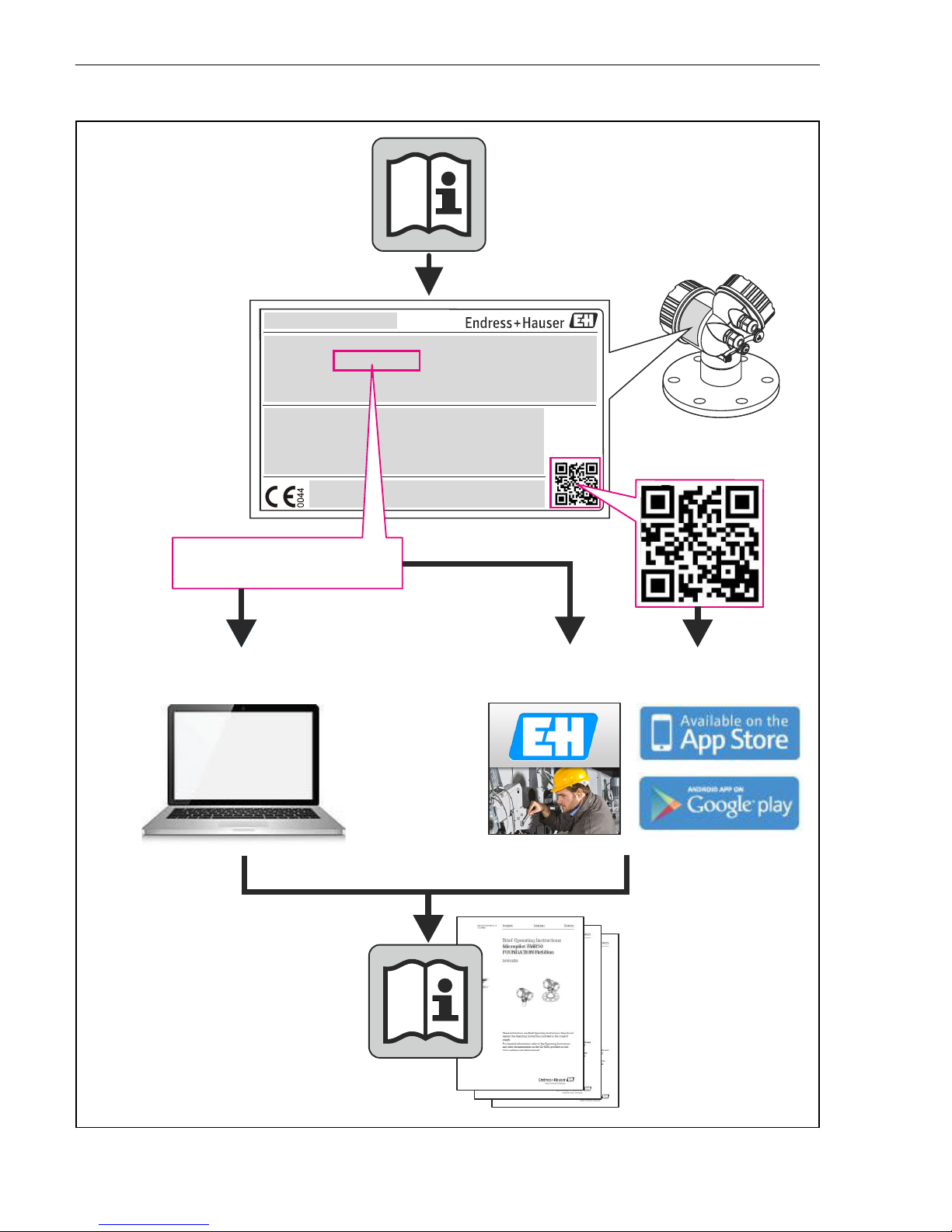
Detailed information about the device can be found in the
Operating Instructions and the other documentation:
Available for all device versions via:
– Internet: www.endress.com/deviceviewer
– Smart phone/tablet: Endress+Hauser Operations App
KA01079F/00/EN/14.15
71282359
Page 2
Levelflex FMP51, FMP52, FMP54 PROFIBUS PA
2 Endress+Hauser
TAG No.: XXX000
Ser. No.: X000X000000
Order code 00X00-XXXX0XX0XXX
www.endress.com/deviceviewer Endress+Hauser Operations App
Serial number
A0023555
Page 3

Levelflex FMP51, FMP52, FMP54 PROFIBUS PA Table of contents
Endress+Hauser 3
Table of contents
1 Important document information ................................................ 4
1.1 Symbols ............................................................................ 4
2 Basic safety instructions ......................................................... 6
2.1 Requirements for the personnel ........................................................... 6
2.2 Designated use ....................................................................... 6
2.3 Workplace safety ...................................................................... 7
2.4 Operational safety ..................................................................... 7
2.5 Product safety ........................................................................ 7
3 Product description .............................................................. 8
3.1 Product design ....................................................................... 8
4 Incoming acceptance and product identification .................................. 9
4.1 Incoming acceptance ................................................................... 9
4.2 Product identification .................................................................. 9
5 Storage, Transport .............................................................. 11
5.1 Storage conditions .................................................................... 11
5.2 Transport product to the measuring point ................................................... 11
6 Mounting ....................................................................... 12
6.1 Mounting requirements ................................................................ 12
6.2 Mounting the device .................................................................. 17
6.3 Post-installation check ................................................................. 25
7 Electrical connection ............................................................ 26
7.1 Connection conditions ................................................................. 26
7.2 Connecting the device ................................................................. 30
7.3 Post-connection check ................................................................. 32
8 Integration into a PROFIBUS network ........................................... 32
8.1 Overview of the device database files (GSD) ................................................. 32
8.2 Set device address .................................................................... 33
9 Commissioning via wizard ...................................................... 35
10 Commissioning (via operating menu) ........................................... 36
10.1 Display and operating module ........................................................... 36
10.2 Operating menu ..................................................................... 39
10.3 Unlock the device .................................................................... 40
10.4 Setting the operating language .......................................................... 40
10.5 Configuration of a level measurement ..................................................... 41
10.6 Configuration of an interface measurement ................................................. 43
10.7 User-specific applications ............................................................... 45
Page 4
Important document information Levelflex FMP51, FMP52, FMP54 PROFIBUS PA
4 Endress+Hauser
1 Important document information
1.1 Symbols
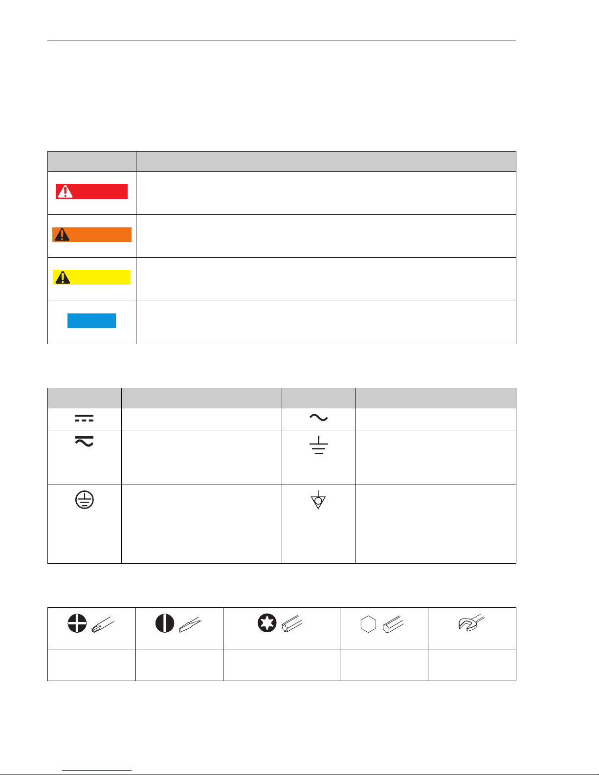
1.1.1 Safety symbols
Symbol Meaning
DANGER
DANGER!
This symbol alerts you to a dangerous situation. Failure to avoid this situation will result in
serious or fatal injury.
WARNING
WARNING!
This symbol alerts you to a dangerous situation. Failure to avoid this situation can result in
serious or fatal injury.
CAUTION
CAUTION!
This symbol alerts you to a dangerous situation. Failure to avoid this situation can result in
minor or medium injury.
NOTICE
NOTE!
This symbol contains information on procedures and other facts which do not result in personal
injury.
1.1.2 Electrical symbols
Symbol Meaning Symbol Meaning
Direct current Alternating current
Direct current and alternating current Ground connection
A grounded terminal which, as far as
the operator is concerned, is grounded
via a grounding system.
Protective ground connection
A terminal which must be connected to
ground prior to establishing any other
connections.
Equipotential connection
A connection that has to be connected
to the plant grounding system: This
may be a potential equalization line or
a star grounding system depending on
national or company codes of practice.
1.1.3 Tool symbols
A0011219
A0011220
A0013442 A0011221
A0011222
Cross-head
screwdriver
Flat blade
screwdriver
Torx screwdriver Allen key Hexagon wrench
Page 5
Levelflex FMP51, FMP52, FMP54 PROFIBUS PA Important document information
Endress+Hauser 5
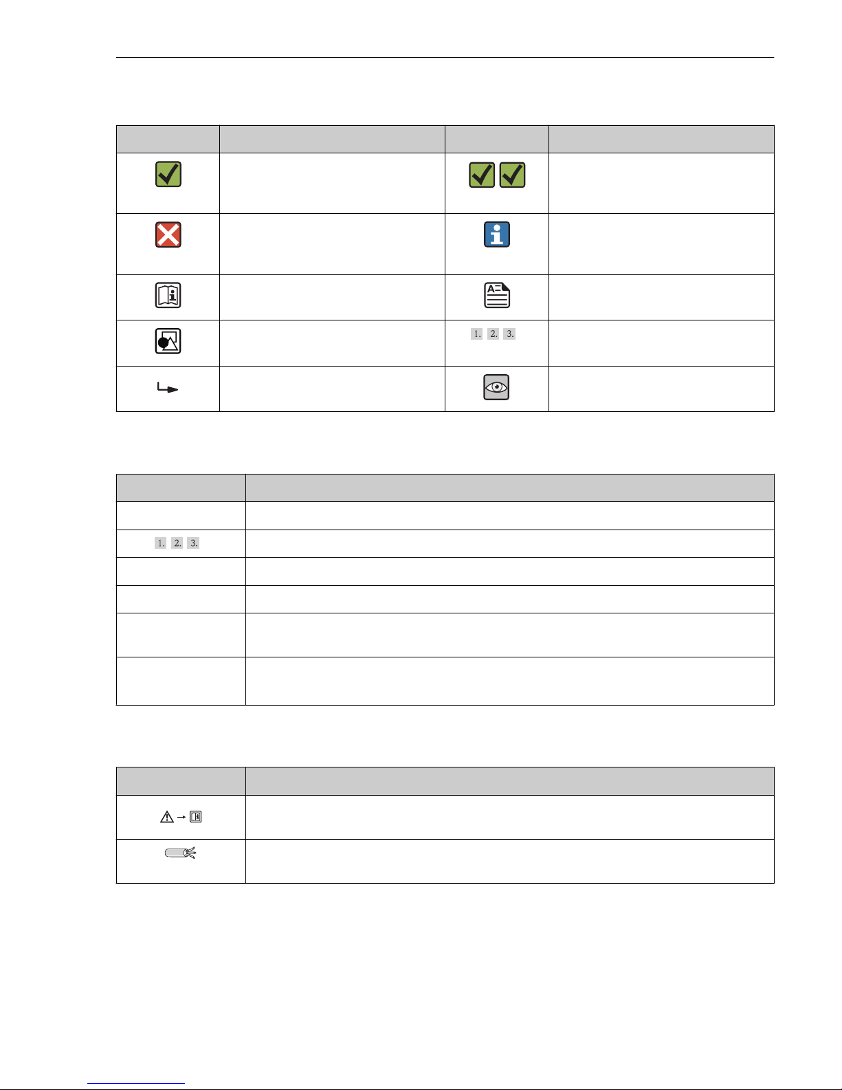
1.1.4 Symbols for certain types of information
Symbol Meaning Symbol Meaning
Permitted
Procedures, processes or actions that
are permitted.
Preferred
Procedures, processes or actions that
are preferred.
Forbidden
Procedures, processes or actions that
are forbidden.
Tip
Indicates additional information.
Reference to documentation Reference to page
Reference to graphic
,…,
Series of steps
Result of a sequence of actions Visual inspection
1.1.5 Symbols in graphics
Symbol Meaning
1, 2, 3 ... Item numbers
,…,
Series of steps
A, B, C, ... Views
A-A, B-B, C-C, ... Sections
-
Hazardous area
Indicates a hazardous area.
.
Safe area (non-hazardous area)
Indicates the non-hazardous area.
1.1.6 Symbols at the device
Symbol Meaning
Safety instructions
Observe the safety instructions contained in the associated Operating Instructions.
Temperature resistance of the connection cables
Specifies the minimum value of the temperature resistance of the connection cables.
Page 6

Basic safety instructions Levelflex FMP51, FMP52, FMP54 PROFIBUS PA
6 Endress+Hauser
2 Basic safety instructions
2.1 Requirements for the personnel
The personnel must fulfill the following requirements for its tasks:
‣
Trained, qualified specialists must have a relevant qualification for this specific function
and task
‣
Are authorized by the plant owner/operator
‣
Are familiar with federal/national regulations
‣
Before beginning work, the specialist staff must have read and understood the instructions
in the Operating Instructions and supplementary documentation as well as in the
certificates (depending on the application)
‣
Following instructions and basic conditions
2.2 Designated use
Application and measured materials
The measuring device described in these Operating Instructions is intended only for level and
interface measurement of liquids. Depending on the version ordered the device can also
measure potentially explosive, flammable, poisonous and oxidizing materials.
Observing the limit values specified in the "Technical data" and listed in the Operating
Instructions and supplementary documentation, the measuring device may be used for the
following measurements only:
‣
Measured process variable: Level and/or interface
‣
Calculated process variable: Volume oder mass in arbitrarily shaped vessels (calculated
from the level by the linearization functionality)
To ensure that the measuring device remains in proper condition for the operation time:
‣
Use the measuring device only for measured materials against which the process-wetted
materials are adequately resistant.
‣
Observe the limit values in "Technical data".
Incorrect use
The manufacturer is not liable for damage caused by improper or non-designated use.
Verification for borderline cases:
‣
For special measured materials and cleaning agents, Endress+Hauser is glad to provide
assistance in verifying the corrosion resistance of wetted materials, but does not accept any
warranty or liability.
Residual risk
The electronics housing and its built-in components such as display module, main electronics
module and I/O electronics module may heat to 80 °C (176 °F) during operation through heat
transfer from the process as well as power dissipation within the electronics. During operation
the sensor may assume a temperature near the temperature of the measured material.
Danger of burns due to heated surfaces!
‣
For high process temperatures: Install protection against contact in order to prevent burns.
Page 7

Levelflex FMP51, FMP52, FMP54 PROFIBUS PA Basic safety instructions
Endress+Hauser 7
2.3 Workplace safety
For work on and with the device:
‣
Wear the required personal protective equipment according to federal/national
regulations.
With divisible probe rods, medium may penetrate into the joints between the indivual parts of
the rod. This medium may escape when loosening the joints. In the case of dangerous (e.g.
aggressive or toxic) media this may cause injuries.
‣
When loosening the joints between the individual parts of the probe rod: Wear appropriate
protective equipment according to the medium.
2.4 Operational safety
Risk of injury.
‣
Operate the device in proper technical condition and fail-safe condition only.
‣
The operator is responsible for interference-free operation of the device.
Conversions to the device
Unauthorized modifications to the device are not permitted and can lead to unforeseeable
dangers.
‣
If, despite this, modifications are required, consult with the manufacturer.
Repair
To ensure continued operational safety and reliability,
‣
Carry out repairs on the device only if they are expressly permitted.
‣
Observe federal/national regulations pertaining to repair of an electrical device.
‣
Use original spare parts and accessories from the manufacturer only.
Hazardous area
To eliminate a danger for persons or for the facility when the device is used in the hazardous
area (e.g. explosion protection, pressure vessel safety):
‣
Based on the nameplate, check whether the ordered device is permitted for the intended
use in the hazardous area.
‣
Observe the specifications in the separate supplementary documentation that is an integral
part of these Instructions.
2.5 Product safety
This measuring device is designed in accordance with good engineering practice to meet stateof-the-art safety requirements, has been tested, and left the factory in a condition in which
they are safe to operate.
It meets general safety standards and legal requirements. It also complies with the EC
directives listed in the device-specific EC Declaration of Conformity. Endress+Hauser confirms
this by affixing the CE mark to the device.
Page 8
Product description Levelflex FMP51, FMP52, FMP54 PROFIBUS PA
8 Endress+Hauser
3 Product description
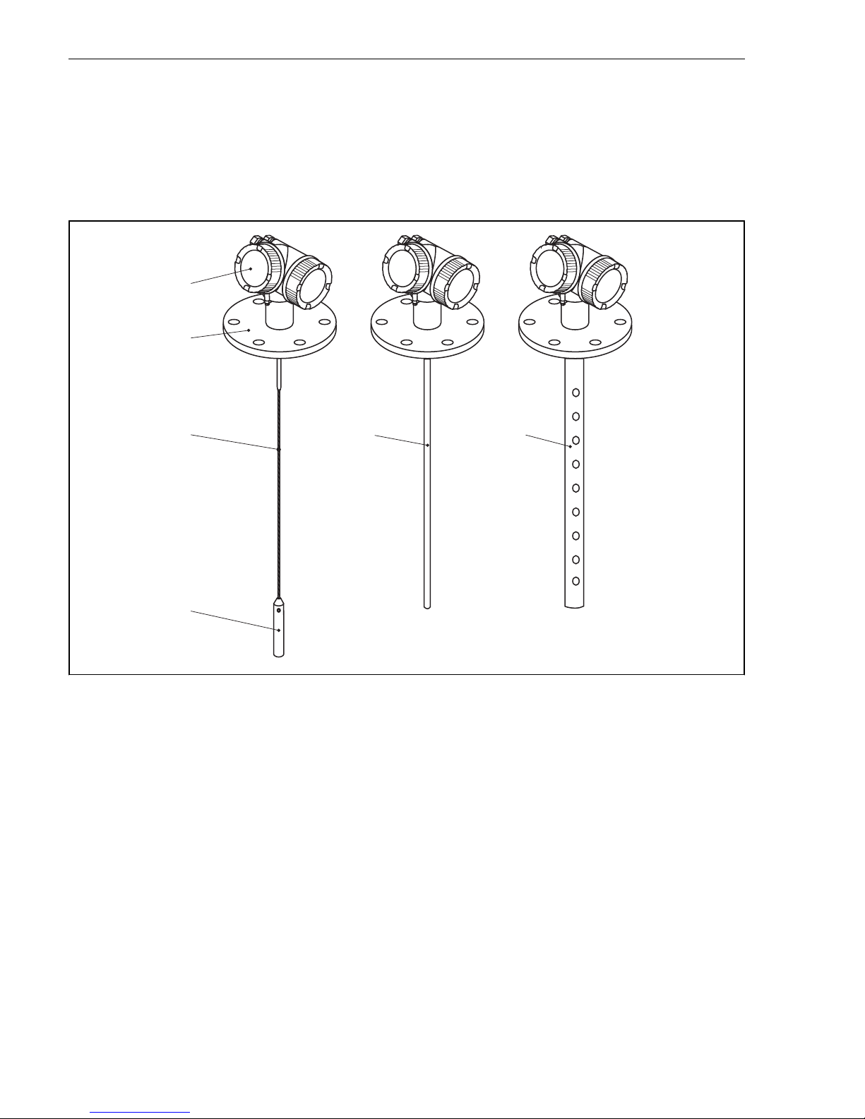
3.1 Product design
3.1.1 Levelflex FMP51/FMP52/FMP54/FMP55
1
2
5
3
4
6
A0012399
1 Design of the Levelflex
1 Electronics housing
2 Process connection (here as an example: flange)
3 Rope probe
4 End-of-probe weight
5 Rod probe
6 Coax probe
Page 9

Levelflex FMP51, FMP52, FMP54 PROFIBUS PA Incoming acceptance and product identification
Endress+Hauser 9
4 Incoming acceptance and product identification
4.1 Incoming acceptance
Upon receipt of the goods check the following:
• Are the order codes on the delivery note and the product sticker identical?
• Are the goods undamaged?
• Do the nameplate data match the ordering information on the delivery note?
• Is the DVD with the operating tool present?
If required (see nameplate): Are the Safety Instructions (XA) present?
If one of these conditions is not satisfied, contact your Endress+Hauser Sales Center.
4.2 Product identification
The following options are available for identification of the measuring device:
• Nameplate specifications
• Order code with breakdown of the device features on the delivery note
• Enter serial numbers from nameplates in W@M Device Viewer
( www.endress.com/deviceviewer ): All information about the measuring device is
displayed.
• Enter the serial number from the nameplates into the Endress+Hauser Operations App or
scan the 2-D matrix code (QR code) on the nameplate with the Endress+Hauser Operations
App: all the information for the measuring device is displayed.
Page 10

Incoming acceptance and product identification Levelflex FMP51, FMP52, FMP54 PROFIBUS PA
10 Endress+Hauser
4.2.1 Nameplate
Order code:
Ext. ord. cd.:
Ser. no.:
Order code:
Ext. ord. cd.:
Ser. no.:
1
2
3
4
A0021952
2 Example of a nameplate
1 Order code
2 Serial number (Ser. no.)
3 Extended order code (Ext. ord. cd.)
4 2-D matrix code (QR code)
For detailed information about interpreting the nameplate specifications, refer to the
Operating Instructions for the device.
Only 33 digits of the extended order code can be indicated on the nameplate. If the
extended order code exceeds 33 digits, the rest will not be shown. However, the complete
extended order code can be viewed in the operating menu of the device in the Extended
order code 1 to 3 parameter.
Page 11
Levelflex FMP51, FMP52, FMP54 PROFIBUS PA Storage, Transport
Endress+Hauser 11
5 Storage, Transport
5.1 Storage conditions
• Permitted storage temperature: –40 to +80 °C (–40 to +176 °F)
• Use the original packaging.
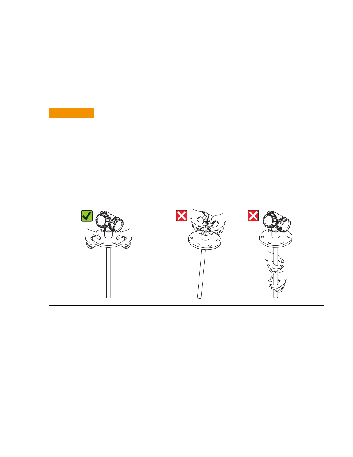
5.2 Transport product to the measuring point
L
WARNING
Housing or probe may be damaged or break away.
Risk of injury!
‣
Transport the measuring device to the measuring point in its original packaging or at the
process connection.
‣
Do not fasten lifting devices (hoisting slings, lifting eyes etc.) at the housing or the probe
but at the process connection. Take into account the mass center of the device in order to
avoid unintended tilting.
‣
Comply with the safety instructions, transport conditions for devices over 18kg (39.6lbs)
(IEC61010).
A0013920
Page 12

Mounting Levelflex FMP51, FMP52, FMP54 PROFIBUS PA
12 Endress+Hauser
6 Mounting
6.1 Mounting requirements
6.1.1 Suitable mounting position
A
C
1
2 3
4
B
A0012606
3 Mounting requirements for Levelflex
Page 13

Levelflex FMP51, FMP52, FMP54 PROFIBUS PA Mounting
Endress+Hauser 13
Mounting distances
• Distance (A) between wall and rod or rope probe:
– for smooth metallic walls: > 50 mm (2 in)
– for plastic walls: > 300 mm (12 in) to metallic parts outside the vessel
– for concrete walls: > 500 mm (20 in), otherwise the available measuring range may be
reduced.
• Distance (B) between rod or rope probe and internal fittings in the vessel: > 300 mm (12 in)
• When using more than one Levelflex:
Minimum distance between the sensor axes: 100 mm (3.94 in)
• Distance (C) from end of probe to bottom of the vessel:
– Rope probe: > 150 mm (6 in)
– Rod probe: > 10 mm (0.4 in)
– Coax probe: > 10 mm (0.4 in)
For coax probes the distance to the wall and to internal fittings is arbitrary.
Page 14

Mounting Levelflex FMP51, FMP52, FMP54 PROFIBUS PA
14 Endress+Hauser
6.1.2 Securing the probe
Securing rope probes
1
A
C
B
2
A0012609
A Sag of the rope: ≥ 1 cm per 1m of the probe length (0.12 inch per 1 ft of the probe length)
B Reliably grounded end of probe
C Reliably isolated end of probe
1: Mounting and contact with a bolt
2 Mounting kit isolated
• The end of the probe needs to be secured under the following conditions:
if otherwise the probe sporadically comes into contact with the wall of the vessel, the outlet
cone, internal fittings or other parts of the installation.
• The end of probe can be secured at its internal thread
rope 4 mm (1/6"), 316: M 14
• The fixing must be either reliably grounded or reliably insulated. If it is not possible to
mount the probe weight with a reliably insulated connection, it can be secured using an
isolated eyelet, which is available as an accessory.
• In order to prevent an extremely high tensile load (e.g. due to thermal expansion) and the
risk of rope crack, the rope has to be slack. Make the rope longer than the required
measuring range such that there is a sag in the middle of the rope that is ≥ 1cm/(1 m rope
length) [0.12 inch/(1 ft rope length)].
Page 15
Levelflex FMP51, FMP52, FMP54 PROFIBUS PA Mounting
Endress+Hauser 15
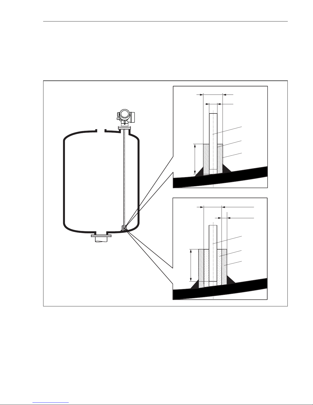
Securing rod probes
• For WHG approvals: For probe lengths ≥ 3 m (10 ft) a support is required.
• In general, rod probes must be supported if there is a horizontal flow (e.g. from an agitator)
or in the case of strong vibrations.
• Rod probes may only be supported at the end of the probe.
mm (in)
ø a
ø b
»50 (1.97)
1
2
3
»50 (1.97)
4
5
6
ø<25 (1.0)
3 (0.12)»
A0012607
1 Probe rod, uncoated
2 Sleeve bored tight to ensure electrical contact between the rod and sleeve!
3 Short metal pipe, e.g. welded in place
4 Probe rod, coated
5 Plastic sleeve, e.g. PTFE, PEEK or PPS
6 Short metal pipe, e.g. welded in place
Page 16

Mounting Levelflex FMP51, FMP52, FMP54 PROFIBUS PA
16 Endress+Hauser
probe a [mm (inch)] b [mm (inch)]
8 mm (1/3") < 14 (0.55) 8.5 (0.34)
12 mm (1/2") < 20 (0.78) 12.5 (0.52)
16 mm (0.63in) < 26 (1.02) 16.5 (0.65)
NOTICE
Poor grounding of the end of probe may cause measuring errors.
‣
Apply a narrow sleeve which has good electrical contact to the probe.
NOTICE
Welding may damage the main electronics module.
‣
Before welding: Ground the probe and dismount electronics.
Page 17

Levelflex FMP51, FMP52, FMP54 PROFIBUS PA Mounting
Endress+Hauser 17
6.2 Mounting the device
6.2.1 Required mounting tools
• For mounting thread 3/4": Hexagonal wrench 36 mm
• For mounting thread 1-1/2": Hexagonal wrench 55 mm
• To shorten rod or coax probes: Saw
• To shorten rope probes:
– Allen key AF 3 mm (for 4mm ropes) or AF 4 mm (for 6 mm ropes)
– Saw or bolt cutter
• For flanges and other process connections: appropriate mounting tools
• To turn the housing: Hexagonal wrench 8 mm
6.2.2 Shortening the probe
When shortening the probe: Enter the new length of probe into the Quick Setup which
can be found in the electronics housing behind the display module.
A0014241
Shortening rod probes
Rod probes must be shortened if the distance to the container floor or outlet cone is less than
10 mm (0.4 in). The rods of a rod probe are shortened by sawing at the bottom end.
Rod probes of FMP52 can not be shortened as they are coated.
Shortening rope probes
Rope probes must be shortened if the distance to the container floor or outlet cone is less than
150 mm (6 in).
Rope probes of FMP52 can not be shortened as they are coated.
Page 18

Mounting Levelflex FMP51, FMP52, FMP54 PROFIBUS PA
18 Endress+Hauser
B
A
C
3 mm
4 (0.16)
60 (2.36)
A0012453
Rope material A B C Torque for set screws
316 4 mm (0.16 in) 40 mm (1.6 in) 3 mm 5 Nm (3.69 lbf ft)
1. Using an Allen key, loosen the set screws at the end-of-probe weight or the clamping
sleeve of the centering disk. Note: The set screws have got a clamping coating in order
to prevent accidental loosening. Thus an increased torque might be necessary to loosen
them.
2. Remove released rope from the weight or sleeve.
3. Measure off new rope length.
4. Wrap adhesive tape around the rope at the point to be shortened to prevent it from
fanning out.
5. Saw off the rope at a right angle or cut it off with a bolt cutter.
6. Insert the rope completely into the weight or sleeve.
7. Screw the set screws into place. Due to the clamping coating of the setscrews application
of a screw locking fluid is not necessary.
Page 19

Levelflex FMP51, FMP52, FMP54 PROFIBUS PA Mounting
Endress+Hauser 19
Shortening coax probes
Coax probes must be shortened if the distance to the container floor or outlet cone is less than
10 mm (0.4 in).
Coax probes can be shortened max. 80 mm (3.2 in) from the end. They have centering
units inside, which fix the rod centrally in the pipe. The centerings are held with borders
on the rod. Shortening is possible up to approx. 10 mm (0.4 in) below the centering unit.
The coax probe is shortened by sawing the pipe at the bottom end.
6.2.3 Mounting the device
Mounting devices with thread
A0012528
Devices with mounting thread are screwed into a welding boss or a flange and are usually also
secured with these.
• Tighten with the hexagonal nut only:
– Thread 3/4": Hexagonal wrench 36 mm
– Thread 1-1/2": Hexagonal wrench 55 mm
• Maximum permissible torque:
– Thread 3/4": 45 Nm
– Thread 1-1/2": 450 Nm
• Recommended torque when using the supplied aramid fibre seal and a process
pressure of 40 bar (580 psi):
– Thread 3/4": 25 Nm
– Thread 1-1/2": 140 Nm
• When installing in metal containers, take care to ensure good metallic contact
between the process connection and container.
Flange mounting
If a seal is used, be sure to use unpainted metal bolts to ensure good electrical contact
between probe flange and process flange.
Page 20

Mounting Levelflex FMP51, FMP52, FMP54 PROFIBUS PA
20 Endress+Hauser
Mounting rope probes
NOTICE
Electrostatic discharges may damage the electronics.
‣
Earth the housing before lowering the rope into the vessel.
*
A0012852
When lowering the rope probe into the vessel, observe the following:
• Uncoil rope and lower it slowly and carefully into the vessel.
• Do not kink the rope.
• Avoid any backlash, since this might damage the probe or the vessel fittings.
6.2.4 Mounting the "Sensor remote" version
This section is only valid for devices of the version "Probe Design" = "Sensor remote"
(feature 600, option MB/MC/MD).
For the version "Probe design" = "Sensor remote" the following is supplied:
• The probe with the process connection
• The electronics housing
• The mounting bracket for wall or pipe mounting of the electronics housing
• The connection cable (length as ordered). The cable has got one straight and one angled
plug (90°). Depending on the local conditions the angled plug can be connected at the probe
or at the electronics housing.
Page 21

Levelflex FMP51, FMP52, FMP54 PROFIBUS PA Mounting
Endress+Hauser 21
L
CAUTION
The plugs of the connection cable may be damaged by mechanical stress.
‣
Mount the probe and the electronics housing tightly before connecting the cable.
‣
Lay the cable such that it is not exposed to mechanical stress. Minimum bending radius:
100 mm (4").
‣
When connecting the cable: Connect the straight plug before the angled one. Torque for
both coupling nuts: 6 Nm.
If the meeasuring point is exposed to strong vibrations, an additional locking compound
(e.g. Loctite 243) can be applied at the plug connectors.
Mounting the electronics housing
122 (4.8)
52 (2)
86
(3.4)
70
(2.8)
140 (5.5)
158 (6.2)
175 (6.9)
A B
ø42...60
(1.65...2.36)
A0014793
4 Mounting the electronics housing using the mounting bracket; dimensions: mm (in)
A Wall mounting
B Pipe mounting
Connecting the cable
Required tools:
Open-end wrench 18AF
Page 22

Mounting Levelflex FMP51, FMP52, FMP54 PROFIBUS PA
22 Endress+Hauser
A
B
6 Nm
(4.42 lbf ft)
6 Nm
(4.42 lbf ft)
6 Nm
(4.42 lbf ft)
C
C
6 Nm
(4.42 lbf ft)
r = 100 (4)
min
r = 100 (4)
min
A0014794
5 Connecting the cable. There are the following possibilities:
A Angled plug at the probe
B Angled plug at the electronics housing
C Length of the remote cable as ordered
6.2.5 Turning the transmitter housing
To provide easier access to the connection compartment or display module, the transmitter
housing can be turned:
Page 23

Levelflex FMP51, FMP52, FMP54 PROFIBUS PA Mounting
Endress+Hauser 23
max.350°
8mm
8mm
A0013713
1. Unscrew the securing screw using an open-ended wrench.
2. Rotate the housing in the desired direction.
3. Tighten the securing screw (1,5 Nm for plastics housing; 2,5 Nm for aluminium or
stainless steel housing).
6.2.6 Turning the display module
+
E
–
1
3mm
A0013905
1. If present: Loosen the screw of the securing clamp of the electronics compartment cover
using an Allen key and turn the clamp 90° conterclockwise.
2. Unscrew cover of the electronics compartment from the transmitter housing.
3. Pull out the display module with a gentle rotation movement.
4. Rotate the display module into the desired position: Max. 8 × 45 ° in each direction.
5. Feed the spiral cable into the gap between the housing and main electronics module and
plug the display module into the electronics compartment until it engages.
6. Screw the cover of the electronics compartment firmly back onto the transmitter
housing.
Page 24

Mounting Levelflex FMP51, FMP52, FMP54 PROFIBUS PA
24 Endress+Hauser
7. Tighten the securing clamp again using the Allen key (Torque: 2.5 Nm).
Page 25

Levelflex FMP51, FMP52, FMP54 PROFIBUS PA Mounting
Endress+Hauser 25
6.3 Post-installation check
m
Is the device undamaged (visual inspection)?
m
Does the device conform to the measuring point specifications?
For example:
• Process temperature
• Process pressure (refer to the chapter on "Material load curves" of the "Technical Information"
document)
• Ambient temperature range
• Measuring range
m
Are the measuring point identification and labeling correct (visual inspection)?
m
Is the device adequately protected from precipitation and direct sunlight?
m
Are the securing screw and securing clamp tightened securely?
Page 26

Electrical connection Levelflex FMP51, FMP52, FMP54 PROFIBUS PA
26 Endress+Hauser
7 Electrical connection
7.1 Connection conditions
7.1.1 Terminal assignment
PROFIBUS PA / FOUNDATION Fieldbus
1
3
+
+
2
4
FIELDBUS
2-channel overvoltage protection
-
-
71128619
[17]
4-20mA/
4-20mA/
B
1
1
+
+
2
2
FIELDBUS
Spare part
71023457
PA/FF
[06/07]
FIELDBUS
-
-
1
3
+
+
2
4
PA/FF
10 mm
Spare part
71108xxx
2- wire level
4-20 mA PFS
FIELDBUS
[26/27]
open
-
-
A
4
1
1
2
3
6
5
3+
3+
4-
4-
A0011341
6 Terminal assignment PROFIBUS PA / FOUNDATION Fieldbus
A Without integrated overvoltage protection
B With integrated overvoltage protection
1 Cable screen: Observe cable specifications
2 Switch output (open collector): Terminals 3 and 4
3 PROFIBUS PA / FOUNDATION Fieldbus: Terminals 1 and 2
Page 27

Levelflex FMP51, FMP52, FMP54 PROFIBUS PA Electrical connection
Endress+Hauser 27
4 Terminal for potential equalization line
5 Cable entries
6 Overvoltage protection module
Page 28

Electrical connection Levelflex FMP51, FMP52, FMP54 PROFIBUS PA
28 Endress+Hauser
7.1.2 Device plug connectors
For the versions with fieldbus plug connector (M12 or 7/8"), the signal line can be
connected without opening the housing.
Pin assignment of the M12 plug connector
21
3
4
A0011175
Pin Meaning
1 Signal +
2 not connected
3 Signal -
4 Ground
Pin assignment of the 7/8" plug connector
2
1
4
3
A0011176
Pin Meaning
1 Signal -
2 Signal +
3 Not connected
4 Screen
Page 29

Levelflex FMP51, FMP52, FMP54 PROFIBUS PA Electrical connection
Endress+Hauser 29
7.1.3 Power supply
PROFIBUS PA, FOUNDATION Fieldbus
"Power supply; Output"
1)
"Approval"
2)
Terminal voltage
E: 2-wire; FOUNDATION Fieldbus, switch output
G: 2-wire; PROFIBUS PA, switch output
• Non-Ex
• Ex nA
• Ex nA[ia]
• Ex ic
• Ex ic[ia]
• Ex d[ia] / XP
• Ex ta / DIP
• CSA GP
9 to 32 V
3)
• Ex ia / IS
• Ex ia + Ex d[ia] / IS + XP
9 to 30 V
1) Feature 020 of the product structure
2) Feature 010 of the product structure
3) Input voltages up to 35 V will not spoil the device.
Polarity sensitive No
FISCO/FNICO compliant
according to IEC 60079-27
Yes
7.1.4 Overvoltage protection
If the measuring device is used for level measurement in flammable liquids which requires the
use of overvoltage protection according to DIN EN 60079-14, standard for test procedures
60060-1 (10 kA, pulse 8/20 μs), overvoltage protection has to be ensured by an integrated or
external overvoltage protection module.
Integrated overvoltage protection
An integrated overvoltage protection module is available for 2-wire HART as well as
PROFIBUS PA and FOUNDATION Fieldbus devices.
Product structure: Feature 610 "Accessory mounted", option NA "Overvoltage protection".
Technical data
Resistance per channel 2 * 0.5 Ω max
Threshold DC voltage 400 to 700 V
Threshold impulse voltage < 800 V
Capacitance at 1 MHz < 1.5 pF
Nominal arrest impulse voltage (8/20 μs) 10 kA
Page 30

Electrical connection Levelflex FMP51, FMP52, FMP54 PROFIBUS PA
30 Endress+Hauser
External overvoltage protection
HAW562 or HAW569 from Endress+Hauser are suited as external overvoltage protection.
For detailed information please refer to the following documents:
• HAW562: TI01012K
• HAW569: TI01013K
7.2 Connecting the device
L
WARNING
Explosion hazard!
‣
Comply with the relevant national standards.
‣
Observe the specifications in the Safety Instructions (XA).
‣
Only use the specified cable glands.
‣
Check whether the supply voltage matches the specifications on the nameplate.
‣
Before connecting the device: Switch the supply voltage off.
‣
Before switching on the supply voltage: Connect the potential bonding line to the exterior
ground terminal.
Required tools and accessories:
• For instruments with safety pin for the lid: AF 3 Allen key
• Wire stripping pliers
• When using stranded wires: Wire end sleeves.
1.
2.
3.
10 (0.4)
10 (0.4)
mm (in)
4.
5.
5.
A0012619
1. Loosen the screw of the securing clamp of the connection compartment cover and turn
the clamp 90° counterclockwise.
2. Unscrew the connection compartment cover.
3. Push the cable through the cable entry. To ensure tight sealing, do not remove the
sealing ring from the cable entry.
Page 31

Levelflex FMP51, FMP52, FMP54 PROFIBUS PA Electrical connection
Endress+Hauser 31
4. Strip the cable.
5. Strip the cable ends 10 mm (0.4 in). For stranded cables, also attach wire end ferrules.
6. Firmly tighten the cable glands.
7.
2
1
4
3
A0013837
Connect the cable in accordance with the terminal assignment → 26.
8. When using screened cable: Connect the cable screen to the ground terminal.
9. Screw the cover onto the connection compartment.
10. For instruments with safety pin for the lid: Adjust the safety pin so that its edge is over
the edge of the display lid. Tighten the safety pin.
7.2.1 Pluggable spring-force terminals
Instruments without integrated overvoltage protection have pluggable spring-force terminals.
Rigid conductors or flexible conductors with cable sleeve can directly be inserted and are
contacted automatically.
To remove cables from the terminal: Press on the groove between the terminals using a flattip screwdriver ≤ 3 mm (0.12 inch) while pulling the cables out of the terminals.
Page 32

Integration into a PROFIBUS network Levelflex FMP51, FMP52, FMP54 PROFIBUS PA
32 Endress+Hauser
mm(in)
≤ 3(0.12)
A0013661
7.3 Post-connection check
m
Are cables or the device undamaged (visual inspection)?
m
Do the cables comply with the requirements?
m
Do the cables have adequate strain relief?
m
Are all cable glands installed, firmly tightened and correctly sealed?
m
Does the supply voltage match the specifications on the transmitter nameplate?
m
Is the terminal assignment correct → 26?
m
If required: Is the protective earth connected correctly ?
m
If supply voltage is present: Is the device ready for operation and do values appear on the display
module?
m
Are all housing covers installed and firmly tightened?
m
Is the securing clamp tightened correctly?
8 Integration into a PROFIBUS network
8.1 Overview of the device database files (GSD)
Manufacturer ID 17 (0x11)
Ident number 0x1558
Profile version 3.02
Page 33

Levelflex FMP51, FMP52, FMP54 PROFIBUS PA Integration into a PROFIBUS network
Endress+Hauser 33
GSD file Information and files under:
• www.endress.com
• www.profibus.org
GSD file version
8.2 Set device address
2
98
3
4
5 6
7
8
1
DIP
ON
A0015686
7 Address switches in terminal compartment
8.2.1 Hardware adressing
1. Set switch 8 to "OFF".
2. Define the address with switches 1 to 7 according to the table below.
The address change becomes effective after 10 seconds. The device restarts automatically.
Switch 1 2 3 4 5 6 7
Value in position "ON" 1 2 4 8 16 32 64
Value in position "OFF" 0 0 0 0 0 0 0
2
98
3
4
5 6
7
8
1
DIP
ON
2 + 8 = 10
A0015902
8 Example of hardware addressing: switch 8 is in position "OFF"; switches 1 to 7 define the address.
8.2.2 Software addressing
1. Set switch 8 to "ON".
Page 34

Integration into a PROFIBUS network Levelflex FMP51, FMP52, FMP54 PROFIBUS PA
34 Endress+Hauser
2. The device restarts automatically. The address remains the same as before (factory
setting: 126).
3. Set the required address via the operating menu: "Setup" menu → Device address
2
98
3
4
5 6
7
8
1
DIP
ON
A0015903
9 Example of software addressing; switch 8 is in position "ON"; the address is defined in the
operating menu (Setup → Device address)
Page 35

Levelflex FMP51, FMP52, FMP54 PROFIBUS PA Commissioning via wizard
Endress+Hauser 35
9 Commissioning via wizard
A wizard guiding the user through the initial setup is available in FieldCare and DeviceCare.
1. Connect the device to FieldCare or DeviceCare (for details refer to the "Operating
options" chapter of the Operating Instructions).
2. Open the device in FieldCare or DeviceCare.
The dashboard (home page) of the device appears:
1
A0025866
1 "Commissioning" button calls up the wizard.
3. Click on "Commissioning" to call up the wizard.
4. Enter or select the appropriate value for each parameter. These values are immediately
written to the device.
5. Click "Next" to switch to the next page.
6. After finishing the last page, click "End of sequence" to close the wizard.
If the wizard is cancelled before all necessary parameters have been set, the device may
be in an undefined state. A reset to the default settings is recommended in this case.
Page 36

Commissioning (via operating menu) Levelflex FMP51, FMP52, FMP54 PROFIBUS PA
36 Endress+Hauser
10 Commissioning (via operating menu)
10.1 Display and operating module
10.1.1 Display appearance
3.1
3.2
2.1
2.2
2.4
2.5
1.1
1.2
1.3
1.4
2.3
2.6
1
2
3
45
ESC
OPEN
OPEN
E
ABC_
DEFG
User
HIJK
LMNO
PQRS
TUVW
XYZ
Aa1
3
4
0
1 2
9
5
6
8
7
20
A0012635
10 Appearance of the display and operation module for on-site operation
1 Measured value display (1 value max. size)
1.1 Header containing tag and error symbol (if an error is active)
1.2 Measured value symbols
1.3 Measured value
1.4 Unit
2 Measured value display (1 bargraph + 1 value)
2.1 Bargraph for measured value 1
2.2 Measured value 1 (including unit)
2.3 Measured value symbols for measured value 1
2.4 Measured value 2
2.5 Unit for measured value 2
2.6 Measured value symbols for measured value 2
3 Representation of a parameter (here: a parameter with selection list)
3.1 Header containing parameter name and error symbol (if an error is active)
3.2 Selection list; marks the current parameter value.
4 Input matrix for numbers
5 Input matrix for alphanumeric and special characters
Page 37

Levelflex FMP51, FMP52, FMP54 PROFIBUS PA Commissioning (via operating menu)
Endress+Hauser 37
10.1.2 Operating elements
Key Meaning
A0013969
Minus key
For menu, submenu
Moves the selection bar upwards in a picklist.
For text and numeric editor
In the input mask, moves the selection bar to the left (backwards).
A0013970
Plus key
For menu, submenu
Moves the selection bar downwards in a picklist.
For text and numeric editor
In the input mask, moves the selection bar to the right (forwards).
A0013952
Enter key
For measured value display
• Pressing the key briefly opens the operating menu.
• Pressing the key for 2 s opens the context menu.
For menu, submenu
• Pressing the key briefly
Opens the selected menu, submenu or parameter.
• Pressing the key for 2 s for parameter:
If present, opens the help text for the function of the parameter.
For text and numeric editor
• Pressing the key briefly
– Opens the selected group.
– Carries out the selected action.
• Pressing the key for 2 s confirms the edited parameter value.
+
A0013971
Escape key combination (press keys simultaneously)
For menu, submenu
• Pressing the key briefly
– Exits the current menu level and takes you to the next higher level.
– If help text is open, closes the help text of the parameter.
• Pressing the key for 2 s returns you to the measured value display ("home
position").
For text and numeric editor
Closes the text or numeric editor without applying changes.
+
A0013953
Minus/Enter key combination (press and hold down the keys
simultaneously)
Reduces the contrast (brighter setting).
+
A0013954
Plus/Enter key combination (press and hold down the keys
simultaneously)
Increases the contrast (darker setting).
++
A0013955
Minus/Plus/Enter key combination (press and hold down the keys
simultaneously)
For measured value display
Enables or disables the keypad lock.
Page 38

Commissioning (via operating menu) Levelflex FMP51, FMP52, FMP54 PROFIBUS PA
38 Endress+Hauser
10.1.3 Opening the context menu
Using the context menu, the user can call up the following menus quickly and directly from
the operational display:
• Setup
• Conf. backup disp.
• Simulation
Calling up and closing the context menu
The user is in the operational display.
1. Press for 2 s.
The context menu opens.
XXXXXXXXXX
kg/h
20.50
Setup
Conf.backupdisp
Simulation
A0014003-EN
2. Press + simultaneously.
The context menu is closed and the operational display appears.
Calling up the menu via the context menu
1. Open the context menu.
2. Press to navigate to the desired menu.
3. Press to confirm the selection.
The selected menu opens.
Page 39

Levelflex FMP51, FMP52, FMP54 PROFIBUS PA Commissioning (via operating menu)
Endress+Hauser 39
10.2 Operating menu
Parameter/Submenu Meaning Description
Language
1)
Defines the operating language
of the on-site display.
BA01006F (Operating Instructions FMP51/
FMP52/FMP54, PROFIBUS PA)
Setup When appropriate values have
been assigned toall setup
parameters, the measured
should be completely configured
in a standard application.
Setup→Mapping Interference echo suppression
Setup→Advanced setup Contains further submenus and
parameters:
• to adapt the device to special
measuring conditions.
• to process the measured
value (scaling, linearization).
• to configure the signal
output.
Diagnostics Contains the most important
parameters needed to detect
and analyze operational errors.
Expert
2)
Contains all parameters of the
device (including those which
are already contained in one of
the above submenus). This
menu is organized according to
the function blocks of the
device.
GP01001F (Description of Device Parameters
FMP5x, PROFIBUS PA)
1) In case of operation via operating tools (e.g. FieldCare), the "Language" parameter is located at "Setup→Advanced
setup→Display"
2) On entering the "Expert" menu, an access code is always requested. If a customer specific access code has not been
defined, "0000" has to be entered.
Page 40

Commissioning (via operating menu) Levelflex FMP51, FMP52, FMP54 PROFIBUS PA
40 Endress+Hauser
10.3 Unlock the device
If the device has been locked, it must be unlocked before the measurement can be configured.
For details refer to the Operating Instructions of the device:
BA01006F (FMP51/FMP52/FMP54, PROFIBUS PA)
10.4 Setting the operating language
Factory setting: English or ordered local language
X X X X X X XX X
20.50
Operation
Setup
Main menu
0104-1
Language
English
Español
Français
Language
English
Deutsch
Ã
0104-1
Ã
Español
Français
Language
English
Deutsch
0104-1
Betrieb
Setup
Hauptmenü
Sprache
Deutsch
0104-1
XXXX
A0013996
11 Using the example of the local display
Page 41

Levelflex FMP51, FMP52, FMP54 PROFIBUS PA Commissioning (via operating menu)
Endress+Hauser 41
10.5 Configuration of a level measurement
F
L
D
E
20 mA
100%
4 mA
0%
LN
R
A0011360
12 Configuration parameters for level measurements in liquids
LN = Length of probe R = Reference point of the measurement
D = Distance E = Empty calibration (= Zero point)
L = Level F = Full calibration (= span)
1. Setup → Device tag
Enter tag for measuring point.
2. Setup → Device address
Enter bus address of the device (only in case of software addressing).
3. Setup → Distance unit
Select distance unit.
4.
Setup → Operating mode
1)
Select Level option.
5. Setup → Tank type
Select tank type.
6. Setup → Tube diameter (only if "Tank type" = "Bypass / pipe")
Enter the diameter of the bypass or stilling well.
1) only visible for devices with "interface measurement" application package
Page 42

Commissioning (via operating menu) Levelflex FMP51, FMP52, FMP54 PROFIBUS PA
42 Endress+Hauser
7. Setup → Medium group
Select medium group (Others or Water based (DC >= 4))
8. Setup → Empty calibration
Enter the distance E between the reference point R and the minimum level (0%).
9. Setup → Full calibration
Enter distance F between the minimum (0%) and maximum (100%) level.
10. Setup → Level
Displays the measured level L.
11. Setup → Distance
Displays the distance D between the reference point R and the level L.
12. Setup → Signal quality
Displays the signal quality of the level echo.
13. Setup → Mapping → Confirm distance
Compare the displayed distance to the real distance in order to start the recording
of the mapping curve
2)
.
2) For FMP54 with gas phase compensation (product structure: feature 540 "Application Package", option EF or EG)
a map must NOT be recorded.
Page 43

Levelflex FMP51, FMP52, FMP54 PROFIBUS PA Commissioning (via operating menu)
Endress+Hauser 43
10.6 Configuration of an interface measurement
Only devices with the respective software option can be used for interface
measurements. This option is selected in the product structure: Feature 540 "Application
package", option EB "Interface measurement".
D
L
L
L
F
L
I
UP
D
I
LN
E
R
0%
100%
DK (DC )
2 2
DK DC
1 1
( )
A0011177
13 Configuration parameters for interface measurements
R = Reference pioint of the measurement DI = Interface distance (Distance from reference point to lower medium)
E = Empty calibration (= zero point) LI = Interface
F = Full calibration (= span) DL = Distance
LN = Length of probe LL = Level
UP = Measured thickness upper layer
1. Setup → Tag description
Enter tag for measuring point.
2. Setup → Device address
Enter bus address of the device (only in case of software addressing).
3. Setup → Distance unit
Select distance unit.
Page 44

Commissioning (via operating menu) Levelflex FMP51, FMP52, FMP54 PROFIBUS PA
44 Endress+Hauser
4.
Setup → Operating mode
3)
Select the Interface option.
5. Setup → Tank type
Select tank type.
6. Setup → Tube diameter (only if "Tank type" = "Bypass / pipe")
Enter the diameter of the bypass or stilling well.
7. Setup → Tank level
Select tank level (Partially filled oder Fully flooded)
8. Setup → Distance to upper connection
In bypasses: Enter distance from reference point R to lower edge of the upper
connection; otherwise: Keep the factory setting
9. Setup → DC value
Enter dielectric constant of the upper medium.
10. Setup → Empty calibration
Enter the distance E between the reference point R and the minimum level (0%).
11. Setup → Full calibration
Enter distance F between the minimum (0%) and maximum (100%) level.
12. Setup → Level
Displays the measured level LL.
13. Setup → Interface
Displays the interface height LI.
14. Setup → Distance
Displays the distance DL between the reference point R and the level LL.
15. Setup → Interface distance
Displays the distance DI between the reference point R and the interface LI.
16. Setup → Signal quality
Displays the signal quality of the level echo.
17. Setup → Mapping → Confirm distance
Compare the displayed distance to the real distance in order to start the recording
of the mapping curve.
3) only visible for devices with "interface measurement" application package
Page 45

Levelflex FMP51, FMP52, FMP54 PROFIBUS PA Commissioning (via operating menu)
Endress+Hauser 45
10.7 User-specific applications
For details of setting the parameters of user-specific applications, see separate
documentation:
BA01006F/00/DE (Operating Instructions FMP51/FMP52/FMP54, PROFIBUS PA)
For the Expert submenu refer to:
GP01001F/00/DE (Description of Device Parameters FMP5x, PROFIBUS PA)
Page 46

Page 47

Page 48

www.addresses.endress.com
*71282359*
71282359
 Loading...