

Page 1
Audio Interface /
Mobile Preamp
Reference ManualReference Manual
TRACKERpre Reference Manual 1
Page 2

Audio Interface / Mobile Preamp
Reference Manual
© 2007 E-MU Systems
All Rights Reserved
Revision: A
E-MU World Headquarters
E-MU Systems
1500 Green Hills Road
Scotts Valley, CA 95066
USA
Asia Pacific, Africa, Middle East
Creative Technology Ltd
31 International Business Park
Creative Resource, Singapore 609921
SINGAPORE
Europe
Creative Labs (Ireland) Ltd
Ballycoolin Business Park
Blanchardstown, Dublin 15
IRELAND
Japan
Creative Media K. K.
Kanda Eight Bldg., 3F
4-6-7 Soto-Kanda
Chiyoda-ku, Tokyo 101-0021
JAPAN
2 E-MU Systems
Page 3

TABLE OF CONTENTS
Introduction .................................................................................5
Package Includes .......................................................................... 6
Computer Requirements ............................................................... 7
Windows ..........................................................................................................7
OS X .................................................................................................................7
Software Installation .................................................................... 8
Windows XP or Windows Vista ..........................................................................8
Note About Windows Logo Testing ................................................................ 8
Uninstalling all Audio Drivers and Applications ................................................8
Macintosh OS X .................................................................................................9
Uninstalling the Audio Drivers and Applications ............................................11
Basic Connections ......................................................................12
Insert Connection Example .........................................................13
Controls & Headphone Output ................................................... 14
Input/Output .............................................................................15
E-MU USB Audio Control Panel ...................................................16
Direct Monitoring .......................................................................17
Tutorials .....................................................................................18
Introduction ....................................................................................................18
Before you Begin... ......................................................................................18
Getting Started with Steinberg Cubase LE 4 (Windows, OS X) ..........................19
1 - Setting up Cubase LE 4 ...........................................................................19
2 - Basic Multitrack Recording .......................................................................21
3 - Recording a MIDI Track using Proteus VX (Windows only) ........................ 23
Getting Started with Cakewalk Sonar 6 LE (Windows) ......................................26
1 - Setting up Sonar 6 LE .............................................................................. 26
2 - Basic Multitrack Recording .......................................................................29
3 - Recording a MIDI Track using Proteus VX .................................................31
Getting Started with Ableton Live Lite 6 (Windows/OS X) .................................36
Before you Begin: ........................................................................................36
1 - Setting up the Preferences .......................................................................36
2 - Follow the Live 6 Lessons ........................................................................38
3 - Running Proteus VX from Ableton Live (Windows only) ............................39
4 - Record a MIDI Track in Live using your MIDI Keyboard .............................42
Other Cool Tips ............................................................................................45
TRACKERpre Reference Manual 3
Page 4

Troubleshooting .........................................................................46
Internet References .................................................................... 48
Forums ........................................................................................................ 48
Useful Information ..................................................................... 49
Cables - balanced or unbalanced? ................................................................... 49
Balanced Cables .......................................................................................... 49
Unbalanced Cables ...................................................................................... 49
Adapter Cables ................................................................................................ 50
Grounding ...................................................................................................... 50
Phantom Power .............................................................................................. 50
Technical Specifications .............................................................. 51
Declaration of Conformity .......................................................... 53
Index ......................................................................................... 55
4 E-MU Systems
Page 5
Introduction
INTRODUCTION
Thank you for your purchase of the E-MU Tracker Pre USB 2.0 Audio Interface/
Mobile Preamp. This interface brings an unparalleled level of USB audio quality to
the Mac or PC, with pristine 24-bit/192kHz A/D and D/A converters, ultra-low
jitter clock, and XTC™ Class-A, ultra-low noise mic/line/hi-Z preamps. The signalto-noise specs of Tracker Pre USB 2.0 are unmatched by any other brand of USB
interface on the market! From its plug-and-play functionality and hands-on
ergonomic design, to professional features like zero-latency direct monitoring,
Tracker Pre will forever change your expectations of USB audio. We’ve also
included the powerful E-MU Production Tools Software Bundle so that you’ll have
everything you need to create, record, edit, and mix your music.
Some of the other key features are detailed below:
• Record and Playback support for a multitude of sample rates: 44.1k, 48k, 88.2k,
96k, 176.4k, 192k. (176.4k &192k available on PC version only)
• E-MU CurrentMorph™ (pat. pend.) phantom power circuit allows bus-powered
+48V without compromising audio performance.
• Insert jacks on both channels allow you to insert compressors, EQs, or other
processors after the XTC™ Class-A, ultra-low noise preamps.
• Hardware zero-latency direct monitoring (mono or stereo) allows you to record
and overdub with no annoying delay
• Can be used as a stand-alone, audiophile-quality microphone preamplifier
using an optional external power supply.
• Independent ground lift switches for both analog TRS inputs help to solve
potential ground loop problems
• Studio-Grade Headphone Amplifier with level control
NOTE
There are some limitations
when operating at higher
sample rates. See page 16
for details.
TRACKERpre Reference Manual 5
Page 6

Package Includes
PACKAGE INCLUDES
• E-MU Tracker Pre USB 2.0 Audio Interface
•USB Cable (2 meters)
• Installation Guide
E-MU Software/Manual Installation CD-ROM (OS X /Windows)
• Windows XP, Windows x64, Windows Vista, Windows Vista x64 Drivers
• Mac OS X 10.4, Mac OS X 10.5 Drivers
• Owner’s Manual and Tutorials
• Adobe Acrobat Reader (Windows only)
E-MU Production Tools Software Bundle DVD (OS X /Windows)
Windows Applications
• E-MU Proteus VX (with over 1000 sounds)
• Cakewalk Sonar 6 LE
• Steinberg Cubase LE
• Celemony Melodyne essential
• IK Multimedia AmpliTube Duo
• SFX Machine LT
4
OS X Applications
• Steinberg Cubase LE
• BIAS Peak Express 5
• Celemony Melodyne essential
• IK Multimedia AmpliTube LE
• SFX Machine LT
•T-Racks EQ
Ableton Live Lite 6 E-MU Edition CD-ROM (OS X, Windows)
• Ableton Live Lite 6 E-MU Edition
Waldorf Edition LE CD-ROM (OS X, Windows)
• Waldorf Edition LE
4
6 E-MU Systems
Page 7

Computer Requirements
COMPUTER REQUIREMENTS
The minimum computer system requirements for the E-MU Tracker Pre USB 2.0
are listed below.
Windows
• Intel® or AMD® processor — 1.2 GHz or faster
• Intel, AMD, or 100% compatible motherboard & chipset
• Microsoft® Windows® XP (SP 2 or greater), Windows XP x64, Windows Vista,
or Windows Vista x64
• 1 available (Hi-Speed) USB 2.0 port *
• 512 MB System RAM
• 900 MB of free hard disk space for full installation
• CD-ROM/CD-RW drive required for software installation
• DVD-ROM drive required for bundled software installation
• XVGA Video (1024 x 768)
OS X
• Apple® Macintosh® G4 800 MHz G4 compatible or Intel-based processor
• Apple Macintosh OS X (10.4.3 or greater)
• 1 Available (Hi-Speed) USB 2.0 port †
• 512 MB System RAM
• 500 MB of free hard disk space for full installation
• CD-ROM/CD-RW drive required for software installation
• DVD-ROM drive required for bundled software installation
• XVGA Video (1024 X 768)
* When connecting the Tracker Pre to a USB 1.1 port on a Windows PC, performance is
limited to 16-bit and 44.1/48 kHz recording and playback.
† USB 1.1 is not supported on the Macintosh
TRACKERpre Reference Manual 7
Page 8

Software Installation
SOFTWARE INSTALLATION
Windows XP or Windows Vista
Follow these instructions to install the Tracker Pre USB 2.0 software and E-MU
Production Tools software bundle on a Windows XP or Windows Vista computer.
1. First connect the Tracker Pre USB 2.0 to your computer using the supplied USB
cable, and turn it on.
2. If Windows prompts you with an Add New Hardware Wizard, click Cancel.
3. Insert the E-MU Software/Manual Installation CD into your CD-ROM drive. If
Windows AutoPlay mode is enabled for your CD-ROM drive, the CD starts
running automatically. If not, from your Windows desktop, click Start->Run
and type d:\setup.exe (replace d:\ with the drive letter of your CD-ROM
drive). You can also simply open the CD and double-click Setup.exe.
4. The installation splash screen appears. Follow the instructions on the screen to
complete the installation. You will have the option to install Tracker Pre, and
Adobe Acrobat Reader.
5. Choose “Continue Anyway” when you encounter the “Windows Logo
Testing” warning screen. See the note below.
6. When prompted, restart your computer.
7. Be sure to register your Tracker Pre so we can advise you of future software
updates and special offers. You can register online at: www.emu.com/register
8. Your Tracker Pre USB 2.0 is now ready to use.
9. Insert the Windows Production Tools Software Bundle DVD into your DVD-
ROM drive.
10. The installation splash screen appears. Follow the instructions on the screen to
complete the installation.
Note About Windows Logo Testing
When you install the Tracker Pre USB 2.0 drivers, you will see a dialog box
informing you either that the driver has not been certified by Windows Hardware
Quality Labs (WHQL), or that the driver is signed by Creative Labs, Inc., and you
will be asked if you would like to continue with the installation.
The Tracker Pre USB 2.0 audio drivers are not certified by WHQL because the
driver does not support some of the features that the Microsoft Windows Logo
Program requires, most notably Universal Audio Architecture (UAA) and Digital
Rights Management (DRM).
Despite this, the Tracker Pre USB 2.0 audio drivers have been rigorously tested
using the same test procedures that a WHQL qualified driver requires, and it passes
in all of the other important categories, including those that measure the relative
stability of the driver. So, it is perfectly safe to install these drivers on your
computer.
Uninstalling all Audio Drivers and Applications
At times you may need to uninstall or reinstall the Tracker Pre USB 2.0 application
and device drivers to correct problems, change configurations, or upgrade
outdated drivers or applications. Before you begin, close the E-MU Audio control
application. Applications running during the uninstallation will not be removed.
1. Click Start -> Control Panel.
2. Double-click the Add/Remove Programs icon.
3. Click the Install/Uninstall tab (or Change or Remove Programs button).
8 E-MU Systems
Page 9

Software Installation
4. Select the E-MU Audio Drivers entry and then click the Change/Remove
button.
5. In the InstallShield Wizard dialog box, select the Remove ALL option.
6. Click the Yes button.
7. Restart your computer when prompted.
You may now re-install existing or updated E-MU device drivers or applications.
To Reinstall the Drivers:
1. Disconnect the Tracker Pre USB connection.
2. Reboot your PC.
3. When the operating system has finished loading, re-connect the Tracker Pre
USB connection. Important! Make sure you are using a USB 2.0 port.
4. The Hardware Wizard will launch when it detects the Tracker Pre. Cancel it!
5. Run the Installer from the Software/Manual Installation CD-ROM.
6. Reboot the PC when asked. If you’re not asked, reboot anyway.
7. Check the Device Manager, Sounds Video and Game Controllers to make sure
the E-MU Tracker Pre|USB is shown.
Macintosh OS X
Follow these instructions to install the Tracker Pre USB 2.0 drivers and software on
a Macintosh OS X computer. First, connect the Tracker Pre to your computer as
shown on page 12
Install the Tracker Pre USB 2.0 Software
1. Insert the E-MU Software/Manual CD-ROM into your CD-ROM drive.
2. Double-click on the E-MU icon on the desktop.
3. Double-click on the Install icon to start the installation.
4. The installation Welcome screen appears. Follow the instructions on the
screen.
5. When the Authenticate dialog box appears, enter the administrator password
you chose when you installed OS X.
6. Continue to follow the instructions on the screen to continue the installation.
You will be given the option to install:
• Easy Install: Installs the following applications and drivers.
E-MU Tracker Pre USB 2.0: USB Drivers and Control Application
• Custom Install: allows you to choose which components are installed.
7. Easy Install is recommended. The software will be quickly installed. When
prompted, restart your computer.
.
8. Be sure to register your Tracker Pre USB 2.0 so we can advise you of future
software updates and special offers. You can register online at:
www.emu.com/register
TRACKERpre Reference Manual 9
Page 10
Software Installation
Set-up the Tracker Pre USB 2.0 as your Default Audio Device
9. Click Go -> Utilities from the menu bar.
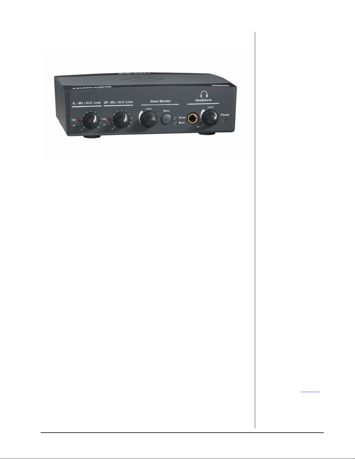
10. Double-click Audio MIDI Setup, then click the Audio Devices button if it’s
not already selected. The window shown on the following page appears.
11. Select the Tracker Pre USB 2.0 for the following: Default Input, Default
Output, System Output, Properties For.
12. Play a song on iTunes to verify that the Tracker Pre USB 2.0 is the default
device for audio playback.
13. Quit iTunes.
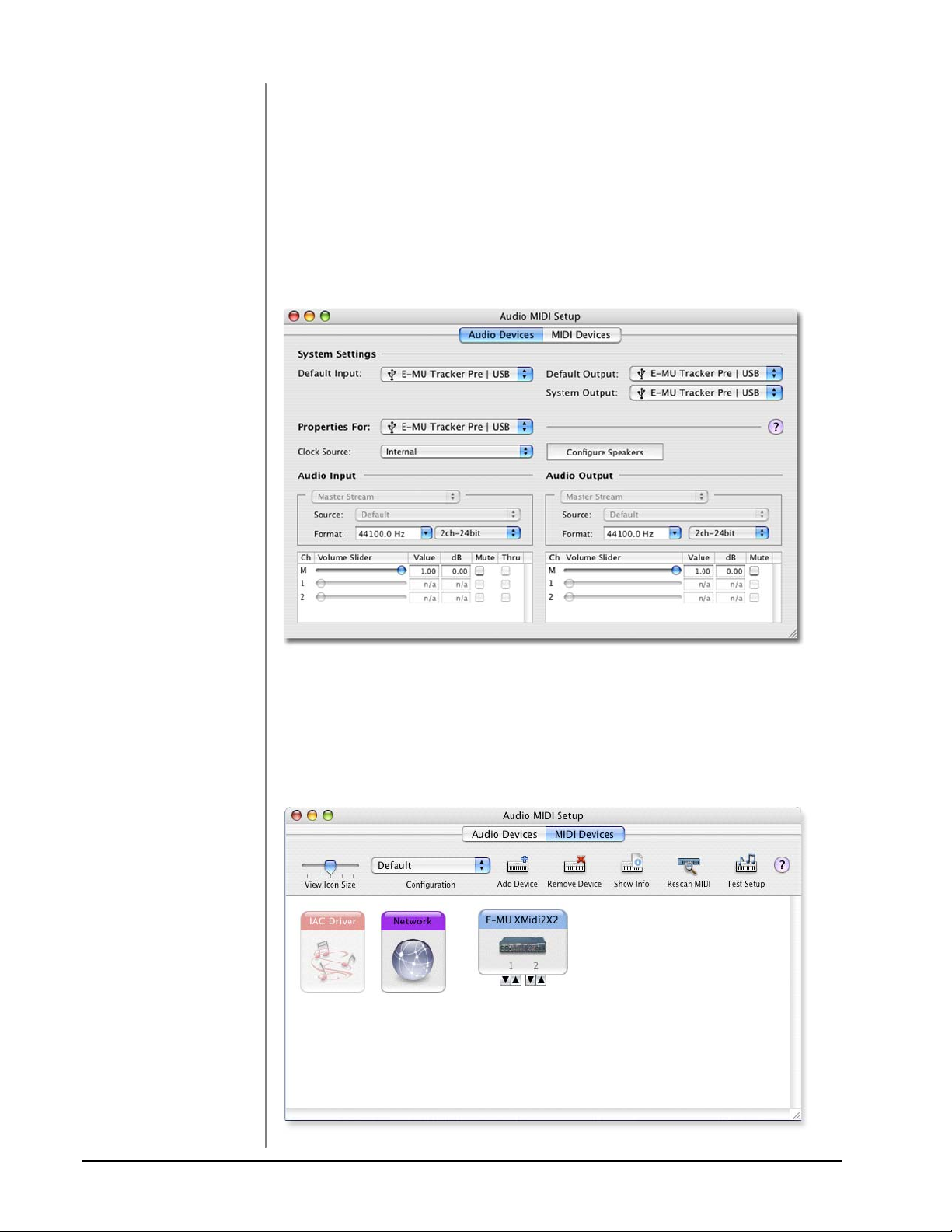
Setup the MIDI Devices
If you plan to use a MIDI keyboard, now would be a good time to set up your MIDI
devices. Connecting a MIDI keyboard will allow you to use the virtual instruments
provided in the software bundle and get the most out of your purchase. You’ll also
need a MIDI interface such as the E-MU Xmidi 2x2 or Xmidi 1x1.
14. Click the MIDI Devices button. The window shown below appears.
10 E-MU Systems
Page 11

Software Installation
15. If you have a USB class-compliant MIDI device connected, it will appear as an
icon in the MIDI Devices window.
16. Press the close button to close the Audio MIDI Setup window.
Install the Production Tools Software Bundle
17. Insert the Macintosh Production Tools CD into your CD-ROM drive.
18. Double-click on the installer package.
19. The installation splash screen appears. Follow the instructions on the screen.
20. Continue to install applications from the bundle as desired.
Uninstalling the Audio Drivers and Applications
At times you may need to uninstall or reinstall the Tracker Pre USB 2.0 application
and device drivers to correct problems, change configurations, or upgrade
outdated drivers or applications. Before you begin, close the E-MU Tracker Pre
Audio control panel application. Applications running during the uninstallation
will not be removed.
1. Open the Applications folder.
2. Open the Creative Professional folder.
3. Open the E-MU USB Audio folder.
4. Click the E-MU USB Audio Unistaller and follow the instructions.
TRACKERpre Reference Manual 11
Page 12
Basic Connections
WARNING!
Use only a USB 2.0
certified Hi-Speed cable
(like the one supplied) for
the USB connection. Using
a USB 1.1 cable may cause
erratic behavior and
degraded performance.
NOTE
The Main Outputs are
balanced and can be used
with either balanced or
unbalanced cables.
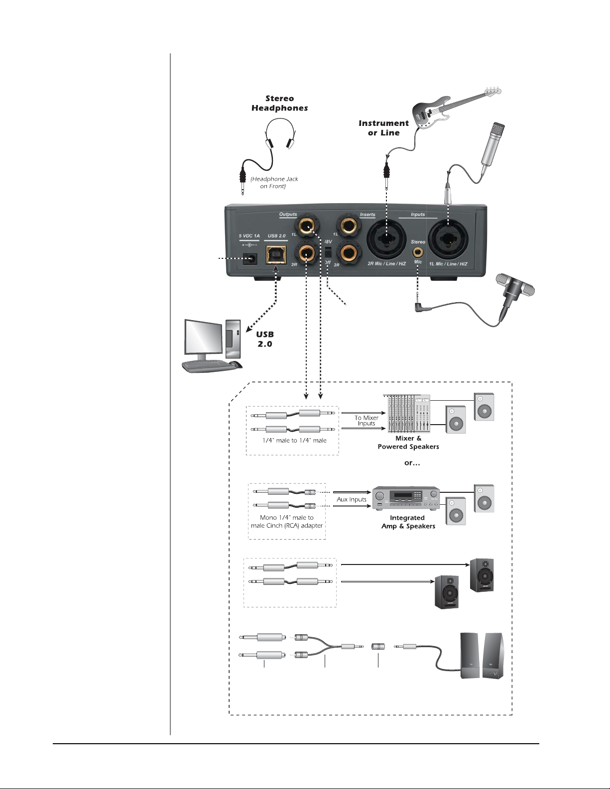
BASIC CONNECTIONS
Optional
External
Power
(for standalone
operation)
(Bus-powered)
Computer
Plug Instrument
or Line Level into
the center of
the receptacle.
Phantom
Power
On/Off
Microphone
or Line
Note: A mono microphone
connects to Input 1L.
Stereo
Electret
Mic
Balanced cables should
ONLY be used when
connecting to a device
with balanced inputs.
(balanced-TRS or unbalanced-TS)
(unbalanced-TS)
1/4” male to 1/4” male
(balanced-TRS or unbalanced-TS)
1/4” male TS
to female RCA
Male RCA to
male stereo 1/8”
Y-c able
Powered Speakers
Stereo 1/8”
stereo-stereo
coupler
Male stereo
1/8” to speakers
Powered
Computer
Speakers
12 E-MU Systems
Page 13
Insert Connection Example
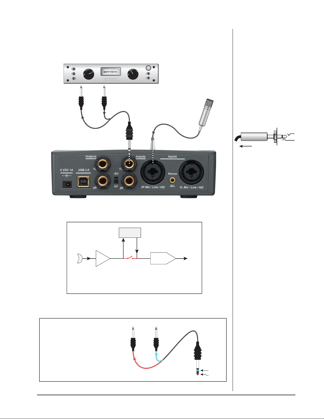
INSERT CONNECTION EXAMPLE
EXTERNAL PROCESSOR
(Compressor, EQ, etc.)
ATTACK
MEDIUM
RELEASE
METER
4
3
SLOW
2
1
RED.
0
FAST SLOW
FAST
OUTPUT
Input Output
Tip Ring
COMPRESSOR
5
6
7
8
9
10
GAIN
1008060
40
112+33570
5
6
4
VU
3
7
BYPASS
LINK
8
2
9
1
0
GAIN REDUCTION
POWER
ON
10
TRS Plug
Mic
TIP . . .
Tracker Pre can be used as
a standalone, high-quality
stereo microphone preamp
if needed.
Insert Jack
Preamp
Output
From
Preamp
To tap off the Mic Preamps
without interrupting the
connection to the ADC,
insert a mono plug halfway
(to the first click) into the
insert jack.
BLOCK
DIAGRAM
Mic Preamp
Inserting a stereo send-return cable into an Insert jack breaks the
connection between the Mic Preamp and the A/D converter and allows
you to insert a serial processing device, such as a compressor or EQ.
SEND/RETURN CABLE
The pre-amplified signal is sent Out the
Tip of the plug and Returns to the
Tracker Pre via the Ring of the plug.
Insert
Device
Tip Ring
USB
A/D Converter
To Effect From Effect
Tip Ring
Return
Send
TRACKERpre Reference Manual 13
Page 14

Controls & Headphone Output
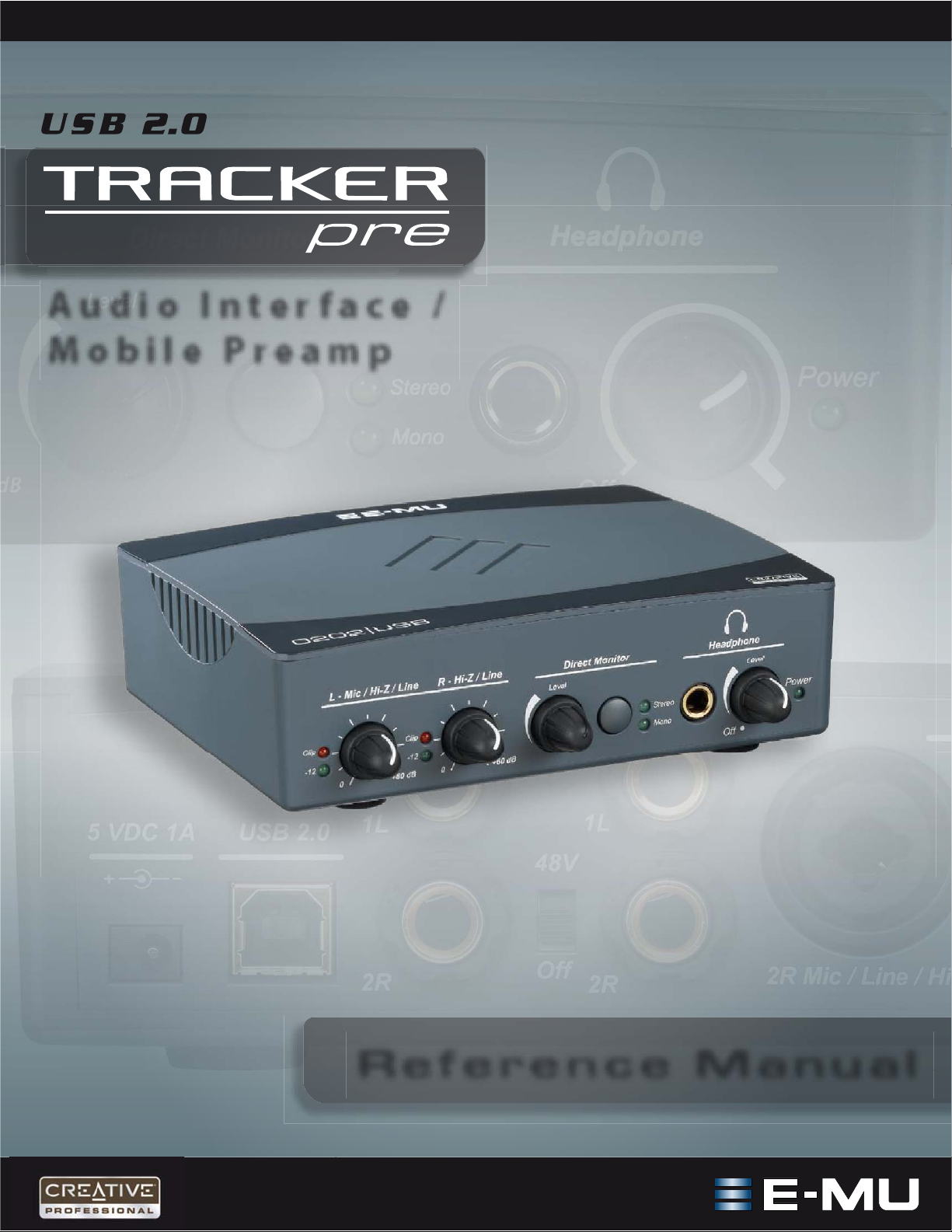
CONTROLS & HEADPHONE OUTPUT
2 34 5 61
1. Signal Level & Clip Indicators
The LED signal level indicators show that you are inputting a proper signal
level. With a proper input level, the green signal LED should be flickering, but
the red clip indicator should NOT ever be lit.
The clip indicators light and show that the input level has exceeded 0dBFS.
2. Left/Right Gain Controls
These controls set the input gain from 0dB to +60dB for the two inputs.
3. Direct Monitor Level Control
This continuous encoder controls the amount of direct monitor signal mixed
into the outputs. The level is adjustable from -24dB to off.
4. Direct Monitor On/Off & Mono-Stereo Switch
Press the button once to turn on Direct Monitoring. The stereo LED illuminates. In this mode the left and right channels are passed through to their
respective outputs at the level set by the Direct Monitor Level control. Press
the button again to switch to Mono Direct Monitoring, which sums the left
and right direct monitor channels to mono. Mono mode is useful when the
two inputs are being used for separate instruments, or when only one input is
being used. See “
5. Headphone Jack
Connect your stereo headphones here.
6. Headphone Level Control
This knob controls the volume of the headphone output. This switch also
turns the Tracker Pre on or off.
Ground Lift Switches
There are “ground lift” switches for both analog 1/4” inputs located on the
bottom of the unit. These switches can be used to safely stop the hum if a
ground loop occurs in your setup. See page 46
Direct Monitoring” on page 17.
for more information.
Input Grounded
R-GND LIFT
L-GND LIFT
The input ground is lifted when the L or R slide switch is closest to the GND LIFT label.
14 E-MU Systems
Input Ground Lifted
Page 15

Input/Output
INPUT/OUTPUT
811 12912137
10
7. 5 VDC Power Adapter (optional)
Although the Tracker Pre is normally bus-powered via USB, it can also be
powered by an external 5-Volt DC power adapter (optional) to allow it to be
used as a stand-alone stereo microphone preamplifier.
8. USB
Connects the Tracker Pre to your computer via the supplied USB cable. The
USB connection provides two-way communication when connected to the
computer.
Since the Tracker Pre receives its power from the USB, always connect to the
USB jack on the computer itself and NOT to a low-power USB connection
that may be present on your computer keyboard or other USB peripheral.
9. Main Outputs (1L & 2R)
The balanced outputs are normally connected to your monitoring system.
Either balanced or unbalanced cables may be used.
The main output volume
can be controlled using the System Volume Control on your Mac or PC. Many
“multimedia” computer keyboards contain System Volume Controls.
10. Phantom Power on/off
This switch turns 48V Phantom Power on or off to the XLR inputs for use with
microphones which require phantom power. See page 50
to learn more.
NOTE to PC Users:
When using a USB 1.1 port,
performance is limited to
16-bit and 44.1/48 kHz
recording and playback.
(USB 1.1 is not supported
on the Macintosh.)
System Volume Control
Mac
PC
11. Inserts (1L & 2R)
These unbalanced TRS jacks allow you to insert a signal processor, such as a
compressor or EQ, after the mic preamps, but before the A/D converter stage.
See “
Insert Connection Example” on page 13.
The Insert jacks can also be used to tap off the mic preamp outputs when
using the Tracker Pre as a stand-alone stereo microphone preamp. Page 13
.
12. Hi-Z / Line / Mic Inputs (1L & 2R)
Use the XLR connector for microphones or balanced line level signals. Use the
1/4¨ jack in the center of the XLR connector as a Hi-Z input for guitar/bass, or
as a line level input. The inputs are balanced, but they accept either balanced
or unbalanced input signals. See page 49
for additional information.
13. Stereo Mic Input
This 1/8” mini-phone jack is designed to accept a stereo, electret condenser
microphone. The jack supplies +5VDC phantom power. Mono microphones
can also be connected and will use input 1L.
• Note: The Stereo Mic jack takes precedence over the Hi-Z/Mic/Line inputs.
Inserting a 1/8” plug disables the other inputs.
TRACKERpre Reference Manual 15
Page 16
E-MU USB Audio Control Panel
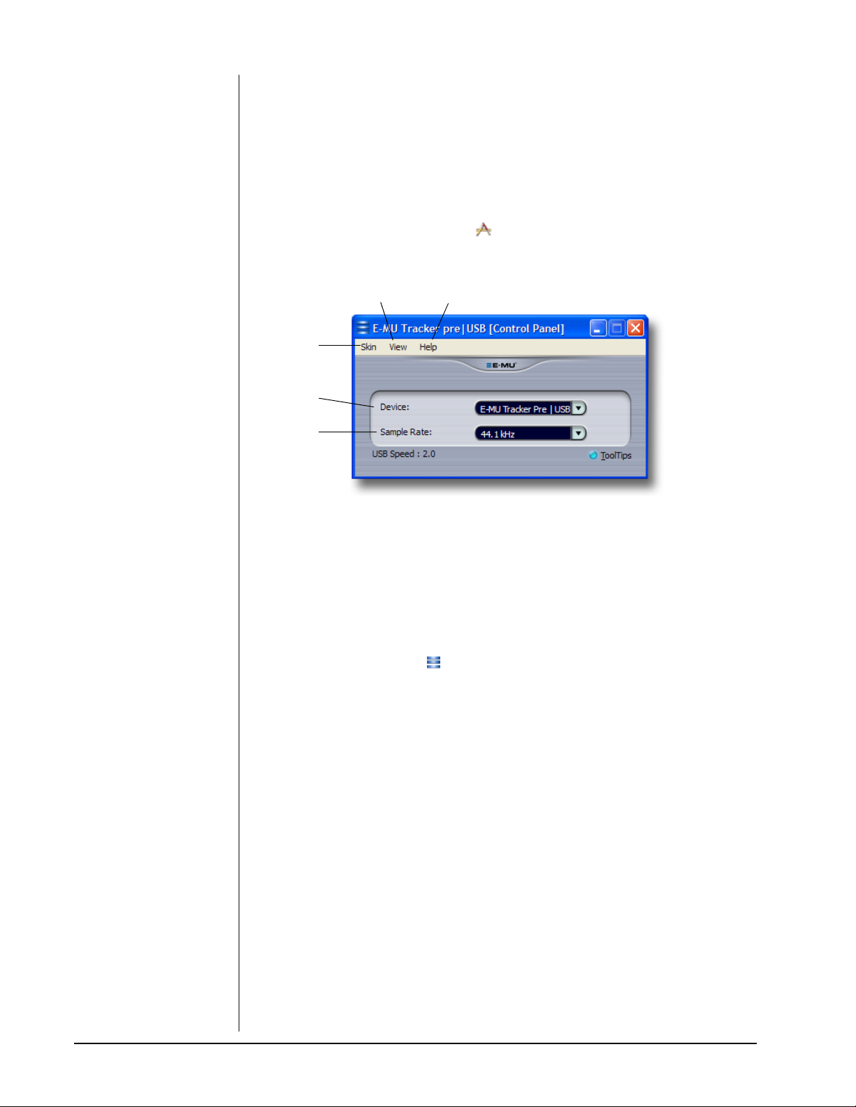
E-MU USB AUDIO CONTROL PANEL
After you have successfully installed the audio drivers, launch the E-MU USB
Audio control panel. The E-MU USB Audio control panel is shown below.
• Windows: The E-MU USB Audio control icon will be visible in the Taskbar,
which is normally located in the bottom right of the screen. It can
also be launched from the Start Menu
(All Programs, Creative Professional, E-MU USB Audio Application).
• OS X The E-MU USB Audio control application is located in the
Applications folder . You can also open the E-Control
Application using the icon on the desktop.
23
1
4
5
NOTE
There are some limitations
when operating at 176.4/
192k sample rates.
PC - No Direct Monitor
Mac - Disabled
1. Skin
Choose between different appearances for the E-MU USB Audio control
panel.
2. View
Hide the application (Ctrl+H, Windows) You can restore the application by
clicking the E-MU icon in the System Tray (Windows), or by clicking the
E-MU icon in the Dock (OS X).
3. Help
About Tracker Pre USB 2.0, Audio control, Launch Manual, Check Updates
4. Device
If you are using more than one E-MU USB Audio device, you can choose
which unit is currently being controlled.
5. Sample Rate
Allows you to set the system sample rate: 44.1kHz, 48kHz, 88.2kHz, 96kHz,
176.4kHz or 192kHz.
16 E-MU Systems
Page 17
Direct Monitoring
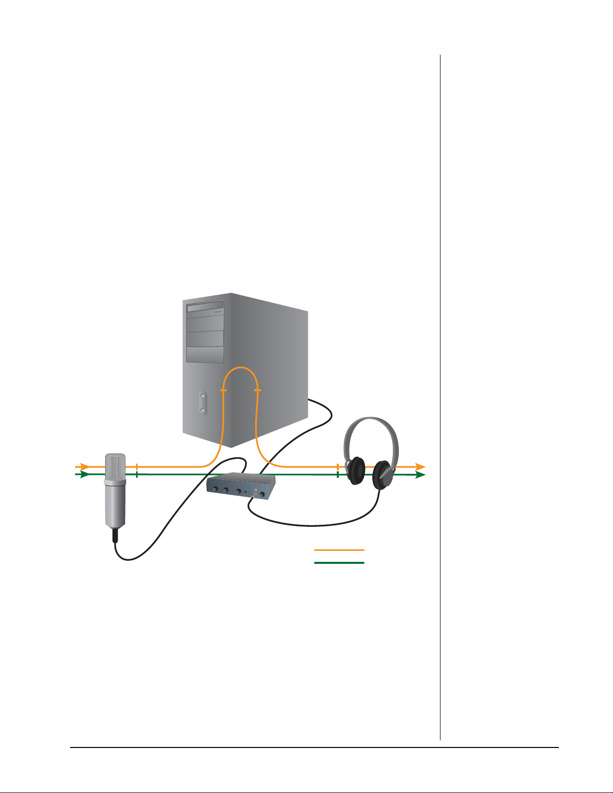
DIRECT MONITORING
Direct monitoring allows you to monitor inputs without having any software
applications open. It can also be used as an alternative to software monitoring if
you desire the lowest latency monitoring possible.
When using a computer for digital recording, an audible time delay occurs while
the audio signal is being input to the computer, processed by the software and then
returned to the output for monitoring. This time delay is called Latency.
Latency becomes a problem when you have to use high buffer settings to conserve
CPU resources. Because the Tracker Pre has hardware direct monitoring, you can
enjoy zero latency regardless of your buffer setting.
The Direct Monitor feature connects the input signals to the output when recording
so that you can hear your performance without delay. The Direct Monitor level
control lets you adjust the volume of the input signal in relation to the recorded
tracks.
Direct monitoring is controlled manually from the Direct Monitor switch on the
Tracker Pre. It’s not necessary to turn it on in your recording application.
Latency (delay)
USB
NOTE
Direct monitoring is not
available when using the
176.4 kHz or 192 kHz
sample rates.
Software Monitoring
Direct Monitoring
Direct Monitoring allows you to listen to the direct sound of your instrument during
recording, without the delay incurred by going to the computer and back.
Direct Monitoring vs. Software Monitoring
Direct monitoring is lower latency and can also be used without software running.
(or even without a computer connected!)
Software monitoring has the advantage of allowing audio effects or EQ added in
the host software to be heard on the output. Its round-trip latency depends on
what latency is chosen in the ASIO/Core Audio configuration. If you choose to
software monitor, make sure to disable direct monitoring. If both are enabled, you
will experience a ‘comb filter’ or doubling effect.
TRACKERpre Reference Manual 17
Page 18

Tutorials
WARNING!
Windows Users After checking your audio,
be sure to quit Windows
Media Player.
TUTO RI ALS
Introduction
This guide contains step-by-step walk-throughs of basic recording operations using
your Tracker Pre interface with software applications for your Windows or
Macintosh OS X computer. We encourage you to perform the steps on your
computer as you read so that you become familiar with the process. The first
tutorial only takes about half an hour to complete, by which time you’ll know how
to make a multitrack recording.
NEED MORE HELP?
If you need additional help with the bundled applications, please see:
• Windows: Program Files\Creative Professional\
E-MU Tracker Pre USB\Documents\3rdParty.htm.
• OS X: Applications Drive\Library\Documentation\
E-MU Tracker Pre USB\ 3rdParty.htm\
Before you Begin...
• You should have already installed the E-MU and Third-Party software on your
computer.
• You should hear the computer sounds coming out of the Tracker Pre and
your speakers when you play a CD or an MP3 using Windows Media Player or
iTunes. If not, make sure your Tracker Pre is properly connected according to
the diagram on page 12
• A source of audio should be connected to the inputs (a microphone, musical
instrument, or CD/MP3 player).
.
18 E-MU Systems
Page 19

Tutorials
Getting Started with Steinberg Cubase LE 4
(Windows, OS X)
Steinberg Cubase LE 4 is a 24-bit, multi-track audio/MIDI sequencer with highquality effects, automation, virtual instruments (VSTi), and many other professional features.
The following step-by-step tutorials are designed to get you recording as quickly as
possible.
1 - Setting up Cubase LE 4
Follow these instructions carefully to ensure that Cubase LE 4 runs smoothly the first
time. Cubase LE 4 will remember these settings, so you’ll only have to do this once.
1. Open Cubase LE 4 from the Start
menu. An ASIO multimedia driver
test dialog box will pop up to ask if
you want to run the ASIO test.
Choose No, because you won’t be
using the driver anyway.
2. Select New Project from the File
menu.
3. Select Empty and click OK.
4. A Select Directory pop-up dialog
box will appear. Choose a location
on your hard disk where you want to
store your audio files, then click OK.
TIP . . .
If you have two or more
hard disks, it’s better to
store audio files on a disk
that isn’t running your
OS.
5. The Cubase LE 4 Project window appears.
6. Select Device Setup… from the Devices menu.
Step 9:
VST
Audio
7. Select VST Audio System from the left pane.
8. Choose ASIO E-MU TRACKER Pre|USB as the ASIO Driver. A pop up dialog
box asks you if you want to keep or switch the ASIO driver. Select Switch.
Buffer Latency Setting
9. Click on ASIO E-MU Tracker Pre|USB (located immediately below VST
Audio System in the Devices pane).
TRACKERpre Reference Manual 19
Page 20

Tutorials
NOTE
If the Cubase LE 4 application crashes for any
reason, it is recommended
that you re-boot the
computer.
Step 10
Control
Panel
Step 9
VST
Audio
10. Click the Control Panel button.
The pop-up dialog box shown at
right appears.
11. Set the ASIO Buffer Latency as low
as your computer will allow and
click OK.
(10ms is a good starting point.)
A low latency setting is important
to assure fast response when using
virtual instruments and to
minimize delay when monitoring
through Cubase. If you hear crackles or other audio problems, try increasing
the Buffer Size.
12. Close the Device Setup screen by clicking OK.
Setting up a New Project
13. Select New Project from File menu in Cubase LE 4. A pop-up Template
selection dialog box appears. Select Empty, then click OK.
TIP . . .
If you have more than one
hard disk, it’s usually best to
store your audio files on a
disk that doesn’t contain
your operating system.
14. Another pop-up dialog box appears asking you to select the directory in which
your audio files will be stored. Choose a location to store your audio files and
click OK.
15. Select Project Setup (Shift +S) from the Project menu. This is where you set
the Sample Rate and Record Format (bit depth), among other things. Set the
Record Format to 24 Bit and the Sample Rate to 44.100 kHz.
20 E-MU Systems
Page 21

Tutorials
2 - Basic Multitrack Recording
This tutorial assumes you’re using a single input or a pair of inputs. For more
advanced recording, refer to the Cubase LE 4 manual.
Add an Audio Track
1. From the Cubase LE 4 menu bar, select Project, Add Track, Audio. A pop-up
dialog box appears, asking you if you would like to add a mono or stereo
track. Choose a mono track for now. After making your selection, click OK. A
new audio track is added to the project window.
Select Mono (or Stereo)
Inspector button
Track Input Routing Monitor Button
2. The Track Input Routing field is where you connect the Tracker Pre inputs to
the track. Left-Stereo In will appear in the Track Input field. (You can change
this to “Right-Stereo In” if you wish.)
3. Make sure the Monitor button is OFF. You will be monitoring the input
through the Tracker Pre.
4. Press the Direct Monitor button on your Tracker Pre USB 2.0. If you are
recording a mono track, set Direct Monitor to Mono by pressing the Direct
Monitor button again.
The Direct Monitor Button
routes the inputs directly
to the outputs.
Get Ready To Record
5. Plug in your instrument or microphone into the 1L (left) input and set the
input gain control for a good signal level. The green -12 signal LED should
come on, but the clip LED should never come on.
6. You should be hearing your instrument or microphone through your monitor
speakers or headphones. If not, go back to steps 4 and 5.
TRACKERpre Reference Manual 21
Page 22

Tutorials
NOTE
Turning on the metronome
adds a 2-bar lead-in before
recording begins.
7. Optional Step - Metronome: To toggle the Metronome on and off, press C on
the computer keyboard. To adjust the metronome output level, press the
transport Play control, then select Metronome Setup... from the Transport
menu. Use the volume slider to set the desired metronome level.
8. Press the Go to Previous Marker / Zero button.
9. Make sure the Record Enable button on the track is on (it should be on by
default).
Record Enable
10. Press the Record button on the Cubase transport control panel. The button
turns red and you’re recording.
Record
Go to Start
PlayStop
11. When you’re finished recording your track, press the Spacebar, or press the
Stop button on the Cubase Transport Control.
12. Press the Go to Zero button.
13. Press the Spacebar or press the Play button to play back your new Track.
Record Another Track
14. Press the Go to Zero button.
15. Drag the audio chunk you just recorded down below itself and release the
mouse button. A new track is automatically created with your recording. This
is a quick and easy way to set up a new track in Cubase. Now you’re all set to
record again on Track 1.
Drag
16. Press the Record button on the Cubase transport control panel and you’re
recording again. You’ll hear your first track playing along with you.
17. Repeat steps 12-14 to record more audio tracks.
18. Press the Mute button to silence any tracks you don’t want to hear.
22 E-MU Systems
Page 23

Tutorials
3 - Recording a MIDI Track using Proteus VX (Windows only)
You’ll need a MIDI interface and a MIDI keyboard (or other MIDI input device)
for this tutorial.
Make the Connections
1. Connect the MIDI out of your MIDI keyboard to the MIDI input of your MIDI
interface.
2. From the Project menu, select Add Track, Instrument.
3. A pop-up dialog box appears asking you to select a VST Instrument. Select
Proteus VX. Select a Count of 1. Click OK.
The Cubase Project Window should now look more or less like the one below
with one or more Audio tracks and one Instrument track:
Instrument
Trac k
NOTE
Selecting a Count of 2 or
more, instantiates multiple
copies of Proteus VX, which
results in very inefficient
usage of your CPU. (See the
note on page 25
NOTE #2
If you have Proteus X or
Emulator X, you can select
these in place of Proteus
VX.
.)
The Inspector
TRACKERpre Reference Manual 23
Page 24

Tutorials
Open VX & Load a Bank
4. Since Proteus VX is a sampler, you need
to load a bank of samples before it can be
played. The Edit Instrument button,
located in the Inspector section of the
window, allows you to edit the virtual
Edit Instrument Button
instrument.
5. Click the Edit Instrument button. The Proteus VX main window appears.
MIDI Channel SelectionPreset Inc/Dec Keys
6. Now we can load the Proteus X Composer bank. Select Proteus X Composer
from the File menu. The bank is installed here: “Program Files\Creative
Professional\ E-MU Sound Central\Proteus X Composer.” Loading takes a few
seconds.
7. Change the Preset using the Inc/Dec keys. You also have to select a preset
before you can hear anything. There are 1024 different presets (sounds) in this
huge bank.
8. Bring up the mini keyboard by clicking the icon on Proteus VX and play a
few notes. You should be hearing sound. If not, verify that the Tracker Pre USB
2.0 is properly configured in Cubase. (See page 19
.)
• If the sound volume is very low, you can decrease the Headroom of Proteus
VX. (Options, Preferences, Headroom/Boost). Keep in mind that with less
headroom, the Proteus VX will be more prone to clipping when multiple
channels are played.
9. Play your MIDI controller and verify that it plays Proteus VX. If not, check to
make sure your MIDI keyboard is set to the same MIDI channel number as
Proteus VX (probably channel 1).
10. Try out the MIDI Controller knobs on your MIDI keyboard. In order for these
to work, the continuous controller numbers of your keyboard knobs must
match those on Proteus VX. (Options, Preferences, Controllers tab).
24 E-MU Systems
Page 25

Tutorials
11. Feel free to play around for awhile and don’t worry about losing anything.
Nothing is made permanent until you Save the bank, so have fun.
To Record a MIDI Track
12. Make sure the Record Enable button on the MIDI track is on (it should be on
by default).
Record Enable
13. Click Record on the Cubase LE Transport control and start playing your MIDI
controller.
Record
14. Press Stop when you’re finished recording the first track.
15. Press the Go To Start button.
16. Press Play on the Cubase Transport to play back your track.
To Record a MIDI Track on another MIDI Channel
NOTE: Proteus VX VSTi can play back up to 16 MIDI tracks at once, however, the
LE version of Cubase 4 only supports a single MIDI channel per VSTi. You could
load another instance of the Proteus VX for each channel, but this is very inefficient
usage of your CPU resources and is NOT recommended. The full version of Cubase
4 does support multiple MIDI channels on a single VSTi.
On Your Own
Cubase LE 4 and Proteus VX include excellent online documentation and help
files. Take the time to learn all the features of these powerful programs, and most
of all have fun.
TRACKERpre Reference Manual 25
Page 26

Tutorials
Getting Started with Cakewalk Sonar 6 LE (Windows)
Sonar 6 LE is a 24-bit multi-track audio/MIDI sequencer with high-quality effects,
automation, virtual instruments (VSTi/DXi), and many other professional features.
The following step-by-step tutorials are designed to get you recording on Sonar LE
6. After you finish the tutorial we encourage you to read the Sonar 6 LE PDF
manual in order to learn about the many features of this comprehensive program.
1 - Setting up Sonar 6 LE
Follow these instructions carefully to ensure that Sonar 6 LE runs smoothly the first
time. Sonar 6 LE will remember these settings, so you’ll only have to do this once.
Run Sonar 6 LE for the first time
1. After installation Sonar 6 LE will automatically open. After completing the
product registration, the following dialog box appears:
2. If you have a MIDI interface or USB keyboard connected (such as the E-MU
Xmidi 2x2 or Xboard), select “Choose MIDI Inputs Now.” If you don’t have a
MIDI interface, select “Continue with No MIDI Input.” A MIDI keyboard is
necessary if you wish to use the Proteus VX sampler.
3. Sonar 6 LE opens and the following dialog box appears.
4. Click Close to close the dialog box. The Sonar Project Window appears.
26 E-MU Systems
Page 27

Tutorials
Set-up the Audio Options
5. From the Options menu, select Audio... The following dialog box appears.
6. Click on the Advanced Tab to access the next window.
7. Select ASIO as the Driver Mode and click OK. You’ll get a pop-up dialog box
explaining that the ASIO settings won’t take effect until the next time you start
Sonar 6 LE.
8. Close Sonar 6 LE completely and restart the application.
TRACKERpre Reference Manual 27
Page 28
Tutorials
Return to the Audio Setup Options
9. Once Sonar 6 LE has restarted, select Audio from the Options menu.
TIP . . .
If you have two or more
hard disks, it’s better to
store audio files on a disk
that isn’t running your OS.
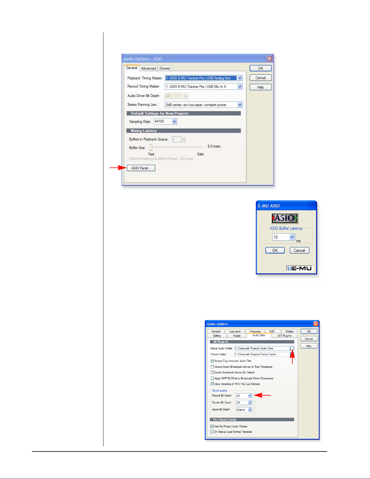
10. Click the ASIO Panel. The pop-up dialog box
shown at right appears.
11. Set the ASIO Buffer Latency as low as your
computer will allow. A low latency setting is
important to assure fast response when using
virtual instruments and to minimize delay when
monitoring through Sonar LE 6. If you hear
crackles or other audio problems, try slightly
increasing the Buffer Size.
12. Close the Audio Options screen by clicking OK.
Note: If the Sonar 6 LE application crashes for
any reason, it is recommended that you re-boot
the computer.
Set the Location of your Audio Files
13. From the Options menu,
select Global.
14. Select the Audio Data tab as
shown at right.
15. Select a location for the
Global Audio Folder. This is
where your large audio files
will be kept.
Step 15
16. Select 24 bits as the Recording
Bit Depth. The Tracker Pre is a
Step 16
24-bit device so why not use
the best possible resolution?
17. Click OK to select your
choices and close Global
Options.
28 E-MU Systems
Page 29
Tutorials
2 - Basic Multitrack Recording
This tutorial assumes you’re using a single input or pair of inputs. Sonar opens by
default with 1 audio track and 1 MIDI track.
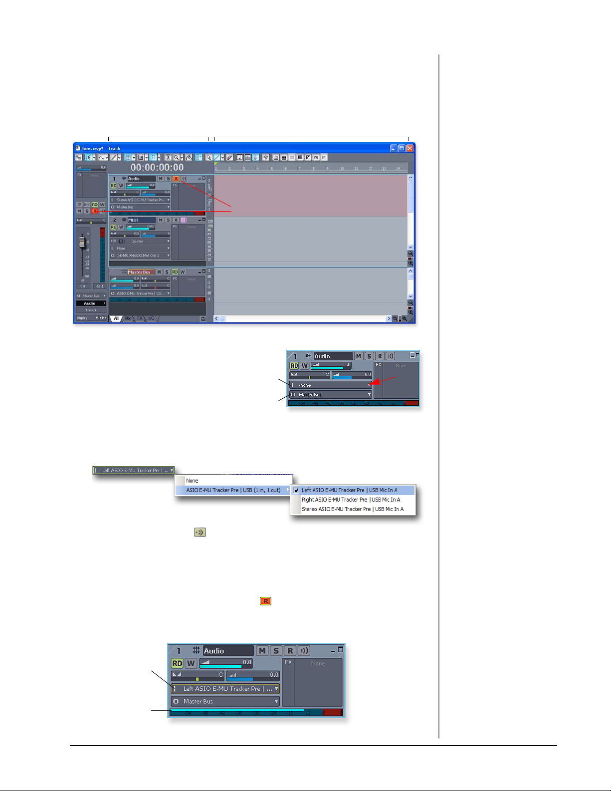
The Sonar Project Window
The Track Pane The Clips Pane
Track Record Enable
Step 5
1. Track 1 is an audio track. Locate
the input and output routing
fields in the Track Pane as shown
at right.
2. Select the input source by clicking
Input
Output
Click
Here
on the small triangle on the input
field. If you wish to record a mono signal on the Left input of the Tracker Pre
USB, select Left ASIO E-MU Tracker Pre|USB Mic In A. To record both inputs
in stereo select Stereo ASIO E-MU Tracker Pre|USB Analog In A.
3. The Input Echo button should be OFF. You will be monitoring the input
through the E-MU Tracker Pre.
4. Press the Direct Monitor button on your Tracker Pre. If you are recording a
mono track, set Direct Monitor to Mono by pressing the Direct Monitor
button again.
5. Press the Track Record Enable button for the track (see the diagram above).
The track turns a dull red color to indicate that it is record-enabled. You
should now see activity on the Track Input Meter when inputting a signal.
Input Select
TIP . . .
If you don’t see meter
activity on the track after
enabling Record, check the
Input for the track. Make
sure you are selecting the
proper input source.
Input Meter
TRACKERpre Reference Manual 29
Page 30

Tutorials
6. If your input signal is either too weak or too strong, adjust the input level
control on the Tracker Pre.
7. Optional Step - Metronome: From the Options Menu, select Project. Select
the Metronome tab. Next select “Use Audio Metronome”. Click OK. Make
sure the Metronome During Record button in the Transport Bar is On.
Record a Track
8. Press Record on the Sonar 6 LE Transport control and start playing.
Return-To-Zero
TIP . . .
You can create a new track
by selecting Clone, from the
Track menu. This handy
feature duplicates the
currently selected track
complete with input/output
routings.
PlayStop
Record
9. Press Stop when you’re finished recording the first track.
10. Press Play on the Sonar 6 LE Transport to play back your track.
11. If you want to dump the track and start over, Right-click over the waveform
display in the track and choose Delete.
Create another Audio Track
12. From the Insert Menu, select Audio Track. Track 3 appears in the Project
window.
Record another Track
13. Select Track 3 and click the Restore Strip Size button to expose the input
and output routing.
14. Set the Input source for the track. Click on the little triangle on the right
side of the track Input box.
15. Disable record for Track 1 by clicking on the Track Record button Off.
16. Enable recording for Track 3 by clicking on the Track Record button On.
17. Press the transport Record button and you’re recording.
Hot Tip: A quick way to record additional tracks using the same input is to simply
drag the Part (audio region) you just recorded up or down to another audio track
in the Sonar Project Window, then just hit Record again and go. (Choose Blend
Old and New when asked in the Drag & Drop Options.)
Save your Project
18. Choose Save As… from the Sonar 6 LE File menu to save your project. Choose
a name and location that will make the project easy to find later.
30 E-MU Systems
Page 31

Tutorials
3 - Recording a MIDI Track using Proteus VX
These instructions explain how to start Proteus VX from within Sonar LE 6. You’ll
need a MIDI interface and a MIDI keyboard (or other MIDI input device) for this
tutorial.
1. Connect the MIDI output of your MIDI keyboard to the MIDI input of your
MIDI interface.
Select the Virtual Instrument
2. From the Insert menu, select
Soft Synths, E-MU, ProteusVX
from the View menu.
3. The following pop-up dialog box appears.
NOTE
Proteus VX can also run as a
standalone application.
4. Select the default options (MIDI Source Track & First Synth Output) as shown.
Click OK to continue. (This may a take a few seconds.) Two new tracks have
been added to the bottom of the track list.
New Proteus VX Tracks
Audio output from Proteus VX
MIDI input to Proteus VX
Click Here...
...to view the MIDI strip controls.
TRACKERpre Reference Manual 31
Page 32

Tutorials
The MIDI Connection
5. Your MIDI Interface should already be selected as the MIDI input in Omni
mode. You can examine this setting if you wish, by clicking on the “Restore
Strip Size” box on the new MIDI track that was created.
• Note: “Omni” mode allows Proteus VX VSTi to receive on all 16 MIDI
channels from your MIDI keyboard. (Proteus VX VSTi is “multi-timbral”
and can assign a different preset to each of the 16 MIDI channels.)
TIP . . .
Check the Sonar MIDI
Monitor in the SysTray to
verify that you’re receiving
MIDI.
Open Proteus VX
6. Double-click on the little keyboard icon in the synth track to open the
Proteus VX editor.
Synth Track with Proteus VX
Double-Click Here
to Open Proteus VX
7. After a few seconds, the Proteus VX editor screen shown below appears.
Preset Inc/Dec keys
MIDI Channel Selection
Load the Proteus X Composer Bank
Before you can play Proteus VX, you have to load a bank of sounds. (This information will be saved when you save your Sonar LE Project.)
8. Open the Proteus X Composer bank. Select Proteus X Composer from the
File menu. The bank is installed here by default: “Program Files\Creative
Professional\ E-MU Sound Central\Proteus X Composer.” Loading takes a few
seconds.
9. Change the Preset using the Inc/Dec keys. (You also have to select a preset
before you can hear anything.) This bank contains 1024 different presets
(sounds).
32 E-MU Systems
Page 33

Tutorials
10. Bring up the mini keyboard by clicking the icon on Proteus VX and play a
few notes. You should be hearing sound. If not, verify that the Tracker Pre is
properly configured.
• Note: If the sound volume is very low, you can decrease the Headroom of
Proteus VX. (Options, Preferences, Headroom/Boost) Keep in mind that
with less headroom, Proteus VX will be more prone to clipping when
multiple channels are played.
11. Play your MIDI controller and verify that it plays Proteus VX. If not, make
sure that your MIDI keyboard is set to the same MIDI channel number as
Proteus VX (probably channel 1). You can also change the MIDI channel of
Proteus VX using the channel Inc/Dec keys shown on the previous page.
Play a Few Presets.
12. To Audition Presets: first highlight the preset number (i.e. ), then scroll
through the presets using the up/down keys on your computer keyboard.
13. Try out the MIDI Controller knobs on your MIDI keyboard.
In order to work, the continuous controller numbers of your keyboard knobs
must match those on Proteus VX. (Refer to the manual that came with your MIDI
keyboard, or change the controller numbers on Proteus VX, located under Options,
Preferences, Controllers tab.)
14. Select the 16 channel tab. This page allows you to select presets for all 16 MIDI
channels.
16 Channel Tab
Select Preset
NOTE
You can also select a single
preset for the track by
selecting the Program
Change number you want.
For some unknown reason,
Sonar 6 LE filters out
program change messages
from a MIDI track.
A Better Way: Assign up
to 16 presets in the Proteus
VX Multisetup and record a
MIDI track for each channel.
15. Select a preset for MIDI Channel 1 by clicking the little triangle.
TRACKERpre Reference Manual 33
Page 34

Tutorials
To Record a M I D I Tr a c k
16. Minimize the Proteus VX window by pressing the minimize button on
Proteus VX.
17. Maximize the Proteus VX MIDI track by pressing the Maximize button.
Maximize
18. The Track Pane expands to show all the track
options, as shown at right. Set the Channel
field (CH) to 1:Proteus VX. (This converts
data on ANY incoming MIDI channel to
Channel 1 data.)
19. Restore the Strip to its normal size by clicking
the “Restore Strip Size” button.
20. Record-Enable the MIDI Track by pressing
the red Record button. The clips pane section of the track turns a dull red
color to indicate that it is record-enabled.
• IMPORTANT: Be sure to turn Track Record Enable OFF for any tracks you
don’t want to record on, such as previously recorded tracks.
Trac k Recor d Ena b l e
21. Verify that you hear the Proteus VX playing as you play your MIDI keyboard.
22. Press Record on the Sonar 6 LE Transport control and start playing.
Record
23. Press Stop (or hit the Spacebar) when you’re finished recording the first track.
24. Press Play on the Sonar 6 LE Transport to play back your track.
To Record a M I D I Tr a c k on another MIDI Channel
Proteus VX VSTi can play back up to 16 MIDI tracks at once with a different preset
on each channel. Using several channels on one VSTi uses far fewer CPU resources
than using multiple VSTi’s with one channel each.
25. Select MIDI Track from the Insert menu. A new MIDI track appears.
26. Make sure Omni is selected as the MIDI input (see below).
27. Make sure Proteus VX is selected as the Output (see below).
34 E-MU Systems
Page 35

Tutorials
28. Select MIDI Channel 2 in
the Ch. field as shown at
right.
29. Record Disable the
previous MIDI track by
clicking the Track Record
Enable button.
30. Record Enable your new
MIDI track by clicking its
Track Record Enable button.
Record Disable this track
Record Enable this track
31. Restore the Proteus VX editor by double-clicking on the little keyboard icon
in the Proteus VX track.
32. Select a preset for channel 2 by clicking the little triangle on channel 2 in the
1-16 channel view of Proteus VX.
33. Play your MIDI keyboard to listen to the presets during the selection process.
34. Click OK when you’ve made your selection.
35. Minimize or close Proteus VX when you’ve made you preset selection.
36. Press Record on the Sonar 6 LE Transport control and start playing.
37. Press Stop when you’re finished recording the second track.
38. Feel free to record additional MIDI tracks. You have 16 MIDI channels.
On Your Own
Now that you’ve had a little taste of what Proteus VX can do, please read the
Proteus VX Operation Manual PDF to learn all about this exceptional instrument.
TIP . . .
The Export Multisample
feature of Proteus VX allows
to to save a bank
containing ONLY the
presets and samples used in
the Multisetup. This gives
you a smaller Project and a
shorter load time.
Sonar 6 LE also includes useful online documentation and help files to help you
learn about the features of this powerful program.
TRACKERpre Reference Manual 35
Page 36

Tutorials
NOTE
The first time you run Live,
you may get the message,
”Audio is disabled. Please
choose an audio output
device from the Audio
Preferences.”
Simply follow the instructions in “1-Setting up the
Preferences” to correct the
situation.
Getting Started with Ableton Live Lite 6 (Windows/OS X)
This guide contains a basic walk-through of Ableton Live Lite 6 (E-MU Edition) to
get you recording and playing back audio. A Proteus VX tutorial is also included for
Windows users. We encourage you to perform the steps on your computer as you
read so that you can “learn by doing.”
Ableton Live Lite 6 is an innovative composition and performance tool. Live
combines digital recording, virtual instruments, and digital effects with an original
interface design that many people find more intuitive than traditional designs.
The following step by step tutorials are designed to get you recording as quickly as
possible. After you’ve finished the tutorial we encourage you to follow Ableton
Live’s excellent interactive Lessons and read the Ableton Live reference manual pdf
in order to learn more about the program.
Before you Begin:
• You should have already installed the Tracker Pre software on your computer
according to the instructions in your “Getting Started” manual.
• You should have already installed the Ableton Live Lite 6 software on your
computer and unlocked it according to the instructions provided with the
Ableton User Manual.
• You should hear sounds from Ableton Live 6 when you play the demos.
• PC Users - You should have already installed the Proteus VX software.
• You should have your MIDI interface and keyboard connected if you want to
record MIDI.
1 - Setting up the Preferences
Unlock Ableton Live Lite 6 for E-MU by following the instructions in the Preferences menu. (Windows - Options menu, Preferences; OS X - Live menu, Preferences)
Read the following instructions to configure the Audio and MIDI preferences. Live
will remember these settings, so you’ll only have to do this once.
Set up the Audio Parameters
1. Click the Audio tab of the Preferences dialog box. The Audio Setup page
appears.
WindowsOS X
2. Select ASIO as the Driver Type. Select ASIO E-MU Tracker Pre|USB as the
Audio Device.
36 E-MU Systems
Page 37

Tutorials
Check the MIDI Parameters
3. Click the MIDI/Sync tab of the Preferences dialog box. The MIDI Setup page
appears.
Windows
Select
MIDI
Interface
NOTE
Live enables every MIDI
input by default.
OS X
4. Your MIDI interface or USB MIDI keyboard should appear in the list. Make
sure it’s selected.
Demo Mode
In order to save your Live Sets, Demo Mode must be Off for all products. Ableton
Live Lite 6 - E-MU Edition installs with Demo mode On for the other Ableton
products such as Operator and Simpler.
5. Select the Products tab.
6. Deactivate Demo Mode for each product that has Demo Mode on.
7. Preference Setup is now complete. Click the close button to close the window.
TRACKERpre Reference Manual 37
Page 38

Tutorials
2 - Follow the Live 6 Lessons
Ableton Live contains built-in tutorials to help you learn your way around. If you
don’t see the Lessons pane on the right side of the window, simply select Lessons
from the View menu.
Click here to
see the Lessons
Follow
these
Lessons
Click here to
see the Lessons
1. The first Lesson - Recording Audio, explains the basics of recording using
your Tracker Pre.
2. Lesson 2 - Playing Software Instruments, is also highly recommended. This
Lesson provides a good background for using Proteus VX VSTi in Ableton Live.
3. After Lessons 1 and 2, feel free to continue on with the rest of the Lessons.
When you’re ready to add Proteus VX to the mix, read on.
38 E-MU Systems
Page 39

Tutorials
3 - Running Proteus VX from Ableton Live (Windows only)
These instructions explain how to run Proteus VX from within Ableton Live Lite 6.
Proteus VX adds a professional-quality sample player and over 1000 new sounds
and integrates perfectly with Ableton Live Lite 6. In this tutorial, you’ll learn how to
use a MIDI keyboard and the pre-recorded MIDI loops that come with Ableton
Live Lite 6 to play Proteus VX.
• In preparation for this tutorial, select the third Live lesson - Improvising With
Loops. If you haven’t already done so, go through the Lesson once until you
are familiar with the concept of loops in Ableton Live.
1. Load the Live Set associated with the Improvising With Loops lesson by
clicking the button shown below.
Click Here
2. The Live Set shown below appears. Press the Play button to check it out.
NOTE
These instructions also
apply to Proteus X or
Emulator X.
Drag
&
Drop
Browser Pane
3. From the Plug-in Device Browser, select
Proteus VX from the E-MU folder.
4. Click and drag the Proteus VX VST icon
over the Clip/Device Drop Area as shown
above. Wait a few seconds. Patience.
5. The Proteus VX editor window appears.
(See the image on the following page.)
Load the Proteus X Composer bank.
6. Open Proteus X Composer from the File menu. The bank is installed here by
default: “Program Files\Creative Professional\ E-MU Sound Central\Proteus
X Composer.” Loading takes a few seconds.
TRACKERpre Reference Manual 39
Page 40

Tutorials
Preset Inc/Dec MIDI Channel Inc/Dec
MIDI Channel
7. Make sure Proteus VX is set to MIDI Channel 1 as shown above.
8. Using the preset increment/decrement
keys, select Preset 0005 - Rock’in B.
Proteus VX
Instrument
9. Close the Proteus VX editor by clicking the
close box. This only hides the editor
screen and doesn’t close Proteus VSTi.
10. Notice that you now have a new MIDI
Track and that the Proteus VX Instrument
now appears at the bottom of the window.
11. Select File Browser 1, open the Clips
folder and open the Keys folder.
12. From the Keys folder, drag and drop one
or more files over to the Clip area on your
Proteus VX MIDI track.
Step 11
(Whurlie -Chords shown)
13. Press the Scene Launch button for the
Verse scene.
14. Drag and drop a few more clips over to the
track and try them out.
40 E-MU Systems
Page 41

Tutorials
Change the Preset from Live
15. When you have a clip you like, click the Clip Overview Hot Spot or simply
double-click on the clip. (Hint: Shift+Tab toggles the view.)
Clip Overview Hot Spot
The Clip View appears at the bottom of the application window.
NOTE
Proteus VX sounds are
called Presets or Programs.
Ableton Live Programs are
offset by +1 from Proteus
VX.
Show/Hide
Notes Box
Program
Select Field
16. Click on the Show/Hide Notes Box to reveal the notes box as shown above.
17. Click on the Program Select field in the Notes box.
A black border appears around the Program field showing that it has the
“focus”. Select any preset number from the pop-up list.
18. Use the Up/Down Arrow keys on your computer keyboard to increment or
decrement through the presets. You can even do this while the clips are
playing to try out sounds in a hurry.
19. Assign different Program Change numbers to different clips and notice that
they are remembered by Live.
TRACKERpre Reference Manual 41
Page 42

Tutorials
4 - Record a MIDI Track in Live using your MIDI Keyboard
Proteus VX is a multi-timbral instrument with the ability to play 16 different
sounds at once. Let’s get ready to make a multitrack MIDI recording.
1. Click the Track View Selector at the bottom of the window or simply doubleclick on the clip to show the Proteus VX Device. (Shift+Tab toggles the view.)
Trac k View S e l ecto r
The Proteus VX Device appears as shown below.
2. Click on the Tool icon to bring up the Proteus VX editor.
16 Channel View
Select Presets
3. Click the 1-16 tab to view the preset selections 16 MIDI channels. When
multitrack recording it’s often easier to give each track its own MIDI channel
and preset.
4. Click the little triangle to the right of the preset selection field for Channel 1.
Click Here
The preset selection dialog box appears.
5. Hit the Spacebar to start Live, then browse though the presets. Click OK
when you find one you want to use for recording.
6. Close the Proteus VX editor by clicking the close box.
42 E-MU Systems
Page 43

Tutorials
7. Open the Preferences via the Options menu (PC) or Live menu (OS X) and
choose the Record/Warp/Launch tab. Set the Count-in to any value other
than “None.” Live doesn’t start recording until the count-in period has elapsed
and gives you time to get ready after pressing “Record.” Close the Window.
8. Delete all the Clips in your MIDI track. (Select a clip and hit backspace to
delete it.)
• If your MIDI interface isn’t already connected, you’ll have to quit Ableton
Live Lite 6, connect the MIDI interface, then restart Ableton Live Lite 6 before
continuing.
9. Set up the MIDI track as shown at left.
a. Select your MIDI Interface in the “MIDI From” field.
b. Monitor should be set to Auto.
c. Set the Audio To = Master
d. Turn Arm Session Record On (red).
10. Play the keyboard. You should hear Proteus VX playing the last sound you
selected on channel 1. Go ahead and change the sound if you wish. (Doubleclick the top of the Track, then click the Wrench icon on the Device Title Bar.
Make sure you’re changing the sound on channel 1.)
Get Ready to Record
a
b
c
11. Start up the Verse using the Scene Launch button and practice playing along
with it.
12. Optional: You can set the Global Quantization value to correct the timing of
your playing. Set it to anything other than “None”.
Quantize
13. Click one of the round MIDI Clip Record buttons to begin
recording. Recording will begin after the Count-In period you
specified.
14. Click the Spacebar to stop recording.
Adjust the Loop Length
15. Start up the Verse using the Scene Launch button and take a listen. You’ll
notice that your part doesn’t line up with the others after the first play
through. This is because your loop length is not a multiple of four bars. Let’s
fix that.
16. Click on the clip you just recorded and your clip will appear at the bottom of
the window. It might look something like the one below.
Loop End Control
d
TRACKERpre Reference Manual 43
Page 44

Tutorials
17. Click and drag the Loop End triangle so that it lines up with the number 5.
Now the loop is exactly 4 bars long and will sync with the rest of the song.
Drag Here
18. Start up the Verse again using the Scene Launch button. Now it should play in
perfect sync.
19. For fun, try changing the Program Number. Remember how?
Click the Show/Hide Notes icon, give Program the focus, then change the
Program number while the scene is playing using the up/down keys.
20. When you’re happy with the recording, disarm recording for the track by
clicking the arm button, turning it grey.
Step 22:
Select
6 -MIDI
Step 23:
List of
Channels
Add Another MIDI Track
IMPORTANT! - Ableton Live Lite 6 - E-MU Edition only allows you to create
four MIDI tracks and we already have four. Solution: Delete track 6 Crash,
which is only used as an accent for the song.
To Delete a Track: Click on the track heading to select it, then press the
Backspace button.
21. From the Insert menu, select Insert MIDI Track (PC - Ctrl+Shift+T; OS X -
). A new MIDI track appears.
22. On the new MIDI Track, the MIDI To box reads “No Output.” Instead, select
6-MIDI. This links the new MIDI track to the MIDI track containing Proteus
VX (Track 7).
23. Click on the box that reads “All Channels” to see the list of
MIDI channels.
24. Select MIDI Channel 2 as shown at right.
Choose a Sound for MIDI Channel 2
25. Click on the 6 MIDI heading to show the Proteus VX VSTi.
Next, click on the wrench icon again to open Proteus VX.
26. Select a Preset on Channel 2. Click the little triangle to the
right of the preset selection field for Channel 2.
Click Here
• Note: There are several ways to select presets. See the
Proteus VX Operation manual pdf for details.
27. Bring up the Mini Keyboard by clicking on the keyboard
icon in the Proteus VX toolbar. Play the mini keyboard to
audition presets.
44 E-MU Systems
Page 45

Tutorials
Get Ready to Record on Channel 2
28. Turn Arm Session Record On. You should now be hearing the preset you
selected on channel 2 when you play your MIDI keyboard.
29. Start up the Verse using the Scene Launch button and practice playing along
with it.
30. Click one of the round MIDI Clip Record buttons to begin
recording. Recording will begin after the Count-In period you
specified.
31. Click the Spacebar to stop recording.
Saving your Work
32. Save your work by selecting Save Live Set As… from the File menu. The next
time you load the set, the Proteus VX bank will automatically load as well.
On Your Own
Now you’ve had a little taste of what Proteus VX and Ableton Live Lite 6 can do.
But don’t stop now! Read the Proteus VX Operation Manual pdf to learn all about
this exceptional instrument.
Ableton Live Lite 6 includes several excellent hands-on tutorials to help you learn
all the features of this ground-breaking music application.
Other Cool Tips
• To control Proteus VX with the knobs on your MIDI keyboard:
Go to the MIDI Preferences on Proteus VX (Options, Preferences, Controllers
tab) and make sure the MIDI Continuous Controller numbers match the ones
your keyboard is sending. You can change the controller numbers on either
your MIDI keyboard or Proteus VX, just as long as they both match.
• To control Proteus VX with the Assignable X/Y Controls in Live:
Simply select the Proteus VX Channel and Proteus VX controller letter A-M for
each axis of the X/Y controller. Open Proteus VX to see what controllers A-M
are controlling. For more information about MIDI controllers please refer to
the Proteus VX pdf manual.
Assign Controllers
TRACKERpre Reference Manual 45
Page 46

Troubleshooting
TROUBL ESHOO TING
Can’t hear Windows Media Player in Windows
If you currently have another audio device installed in your PC, or have had one
installed in the past, you may have to set the Tracker Pre USB 2.0 as the “Default
Audio Device”.
1. Open the Control Panel, then select Sounds and Audio Devices.
2. Click the Audio tab and select E-MU Tracker Pre USB 2.0 as the Default device
under Sound Playback.
3. Click the Volume button under Sound Playback and turn up Wave volume.
You cannot record or monitor ASIO and WAVE at the same time. The first audio
application you open will control the Tracker Pre.
Lost Communication
Should you lose communication between your E-MU Tracker Pre and an audio
application (Ableton Live, Cubase, Sonar, etc.), the Tracker Pre USB 2.0 drivers
may need to be re-selected in your application.
1. Go to your application's I/O settings, de-select the E-MU Tracker Pre USB 2.0
for both input and output.
2. Apply these changes and exit the dialog.
3. Re-enter the application's preference settings and re-select the E-MU Tracker
Pre USB 2.0 drivers. If this doesn’t work, the application may need to be
restarted.
Ground Loops
In digital audio devices and computers, audio ground loops may appear as pitched
tones, digital hash in the background, as well as the familiar 60 cycle hum.
Ground loops are caused by a difference in ground potential between two pieces of
equipment. Computer audio devices are particularly susceptible to ground loops
because most computers were not designed with high quality audio in mind.
Tracker Pre contains built-in “ground lift” switches for the 1/4” analog inputs in
order to safely break the loop if a ground loop occurs in your setup. The XLR
connectors do not have ground lifts.
Input Grounded
R-GND LIFT
L-GND LIFT
The ground-lift switches are located on the bottom of the unit, close to the rear
panel. The input ground is lifted when the L or R slide switch is closest to the GND
LIFT label.
Pops & Crackles
Pops and crackling noises in the audio are most often caused by having the ASIO
Buffer Size set too low. Adding audio tracks and VST plug-ins increases the load on
your computer’s CPU. If your computer cannot keep up with all the tasks you are
asking it to perform, pops and crackles may occur. In effect, increasing the ASIO
buffer gives your computer “more time” to complete its assigned tasks. The
hardware Direct Monitor feature of the Tracker Pre allows you to increase the ASIO
Buffer setting without the associated latency problems during recording and
overdubbing. USB hubs can create problems with digital audio and should be
avoided whenever possible.
Input Ground Lifted
46 E-MU Systems
Page 47

Troubleshooting
Simultaneous WDM/ASIO Playback (PC only)
The Tracker Pre USB 2.0 only supports playing back one stream format at a time on
the PC. Each of the two mentioned stream types has an associated priority. If a
higher priority stream type is opened while a lower priority stream is already
playing, the lower priority stream will stop playing. ASIO has the highest priority,
followed by WDM.
Tracker Pre USB 2.0 vs. USB 1.1 Operation (PC only)
The Tracker Pre can operate in either USB 2.0 or USB 1.1 modes on the PC. To use
the 88.2 kHz, 96 kHz, 176.4 kHz and 192 kHz sample rates, you must be operating
in USB 2.0 mode. The included E-MU USB Audio Control panel software includes
an indicator to let you know which mode the device is running in.
Tracker Pre USB 2.0 comes up in USB 1.1 mode (PC only)
To verify the USB operation mode (1.1 or 2.0), launch the E-Control application.
The USB mode being used is displayed in the lower part of the window.
• Your computer may contain both USB 1.1 and USB 2.0 ports. Try using the
USB ports on the rear of your computer.
• Always turn the power off to Tracker Pre using the front panel control before
connecting or disconnecting the USB cable. Hot-plugging the unit with the
power on can cause the Tracker Pre to power-up in USB 1.1 mode. If you see
the Windows message, “This device could perform faster…”, simply turn
power off, wait a few seconds, then turn power on again.
Using Tracker Pre with Older Versions of Emulator X/Proteus X
Tracker Pre will not function as a dongle for Emulator X or Proteus X software
versions below Ver. 2.5. If you have older versions of these products, you must
upgrade to 2.5 in order to use Tracker Pre as a dongle. Older versions of Proteus
XLE or Proteus VX will continue to operate normally.
TRACKERpre Reference Manual 47
Page 48

Internet References
INTERNET REFERENCES
The internet contains vast resources for the computer musician. A few useful sites
are listed here, but there are plenty more. Check it out.
Software Updates, Tips & Tutorials . http://www.emu.com/support
Setting up a PC for Digital Audio .... http://www.musicxp.net
Audio Recording................................. http://www.recording.org
MIDI & Audio Recording................... http://www.midiworld.com
MIDI & Audio Recording................... http://www.synthzone.com
Sonar Users Group............................ http://www.cakewalknet.com/index.php
Cubase, ASIO & Digital Audio.......... http://www.steinberg.net
ASIO, Cubase & Digital Audio.......... http://www.steinbergusers.com/cubasele/
le_support.php
Cubase Users Group .......................... http://www.groups.yahoo.com/group/
cubase/messages
Forums
Unofficial E-MU Forum..................... http://www.productionforums.com/emu
Sound-On-Sound Forum .................. http://www.soundonsound.com
Computer Music Forum .................... http://www.computermusic.co.uk/main.asp
Home Recording Forum.................... http://homerecording.com/bbs
Studio Central Forum ........................ http://www.tweakheadz.com
KVR Forum .......................................... http://www.kvr-vst.com/forum/search.php
MIDI Addict Forum ........................... http://forum.midiaddict.com/search.php
Sound Card Benchmarking............... http://audio.rightmark.org
Driver Heaven Forum ........................ http://www.driverheaven.net
48 E-MU Systems
Page 49

Useful Information
USEFUL INFORMATION
Cables - balanced or unbalanced?
All inputs and outputs on the E-MU Tracker Pre are designed to use EITHER
balanced or unbalanced cables. Balanced signals provide an additional +6 dB of
gain on the inputs and are recommended for best audio performance, although
unbalanced cables work fine for most applications. If you’re having problems with
hum and noise, or just want the best possible performance, use balanced cables.
Balanced Cables
Balanced cables are used in professional studios because they cancel out noise and
interference. Connector plugs used on balanced cables are XLR (3-prong mic
connector) or TRS (Tip, Ring, Sleeve) 1/4" phone plugs.
Balanced XLR
Connectors
WARNING!
Balanced cables should
ONLY be used when
connecting to a device with
balanced inputs. Ignoring
this rule can actually
INCREASE noise and hum!
Balanced 1/4”
TRS Connectors
Unbalanced 1/4”
Connectors
Balanced cables have one ground (shield) connection and two signal-carrying
conductors of equal potential but opposite polarity. There is one “hot” or positive
lead and a “cold” or negative lead. At any point in time, both conductors are equal
in voltage but opposite in polarity. Both leads may pick up interference, but
because the interference is present both in and out of phase it cancels out at the
balanced input connection.
Unbalanced Cables
Unbalanced cables have one conductor and one ground (shield) and usually
connect via unbalanced 1/4" phone plugs or RCA phono plugs. The shield stays at
a constant ground potential while the signal in the center conductor varies in
positive and negative voltage. The shield completely surrounds the center “hot”
conductor and is connected to ground in order to intercept most of the electrical
interference encountered by the cable. Unbalanced cables are more prone to
ground loops, hum and interference than balanced cables, but the shorter the
cable, the less hum and noise will be introduced into the system.
TRACKERpre Reference Manual 49
Page 50

Useful Information
V
Adapter Cables
1/8” Mini-phone to 1/4” Adapters
To connect headphones with an 1/8” (mini-phone) plug to the headphone jack on
the MicroDock, you’ll need a 1/8” to 1/4” adapter. These handy devices are
available at electronic department stores everywhere.
Cinch (RCA) to 1/4” Adapters
Equipment (such as consumer audio gear) which uses Cinch/RCA type connectors
can be connected to the MicroDock using readily available adapter cables. These
adapters can be found at most stores that sell audio equipment.
1
(grd)
3
2
+48
Grounding
In order to obtain best results and lowest noise levels, make sure that your
computer and any external audio devices are grounded to the same reference. This
usually means that you should be using grounded AC cables on both systems and
make sure that both systems are connected to the same grounded outlet or strip.
Failure to observe this common practice can result in a ground loop. 60 cycle hum
in the audio signal is almost always caused by a ground loop.
Phantom Power
Phantom power is a DC voltage (+48 volts) which is normally used to power the
preamplifier of a condenser microphone. Some direct boxes also use phantom
power.
Pins 2 and 3 of the MicroDock microphone inputs each carry +48 volts DC referenced to pin 1. Pins 2 and 3 also carry the audio signal which “rides” on top of the
48 volt DC. Coupling capacitors at the input of the Tracker Pre block the +48 volt
DC component from the preamplifiers and A/D converters. The audio mutes for a
second when phantom power is turned on.
After turning phantom power off, wait two full minutes before recording to allow
the DC bias to drain from the coupling capacitors, since the bias could affect the
audio headroom.
Balanced dynamic microphones are not affected by phantom power. An unbalanced dynamic microphone may not work properly, but will probably not be
damaged if phantom power is left on.
Ribbon microphones should NOT be used with phantom power on. Doing so can
seriously damage the ribbon element. However, since ribbon microphones are
fairly specialized and generally expensive, you’ll know if you own one. Most
microphones are either of dynamic or condenser type and these will not be
harmed by phantom power.
50 E-MU Systems
Page 51

Technical Specifications
TECHNICAL SPECIFICATIONS
General
Sample Rates: 44.1, 48, 88.2, 96, 176.4, 192kHz from internal crystal with no
sample rate conversion
(Note: 176.4k & 192k sample rates not supported on Macintosh)
Bit Depth: 24-bit I/O, 32-bit processing
USB 2.0 Hi-Speed
Full 24-bit resolution at all sample rates
2 input and 2 output channels
Zero-latency direct hardware monitoring (disabled at 176.4/192kHz)
ASIO2, WDM MME, Apple Core Audio and Core MIDI drivers
Anti-Pop speaker protection minimizes noise during power on/off
Ultra-low jitter clock subsystem: <100ps RMS
Combo Microphone Preamplifier/Hi-Z/Line Input (2)
Type: Balanced combo mic preamplifier and Hi-Z/line input
A/D converter: AK5385
Phantom Power: Phantom-Z™ bus powered, E-MU CurrentMorph™,
(patent-pending)
Microphone Input
Type: Balanced
Input Impedance: 1.5 K Ohms
Max Level: balanced: +6.4dBV; unbalanced: +8.6dBu
EIN: (20Hz-20kHz, 150ohm, unweighted) -127dBu
Signal-to-Noise Ratio: (A-weighted, min. gain) 112dB
THD+N: (1kHz at -1dBFS, min. gain) -102dB (.0007%)
Gain Range: +60dB
Frequency Response: (min. gain, 20Hz-20kHz) +0.0/-0.03dB
Stereo Crosstalk: (1kHz min. gain, -1dBFS) < -111dB
Hi-Z Input
Type: Balanced (can be used with unbalanced cables)
Input Impedance: 1M ohms
Max Level: balanced: +6.9dBV; unbalanced: +9.1dBu)
Dynamic Range: -113dB
Signal-to-Noise Ratio: (A-weighted, min. gain) -108dB
THD+N: (1kHz at -1dBFS, min. gain) -102dB (.0007%)
TRACKERpre Reference Manual 51
Page 52

Technical Specifications
Analog Line Outputs (2)
Type: balanced, AC-coupled, 2-pole low-pass differential filter
D/A converter: CS4392
Max Level: Consumer: +6.6dBV max (unbalanced)
Frequency Response: (20Hz - 20kHz) 0.00/-0.08dB
Dynamic Range: (1kHz, A-weighted) 112dB
Signal-to-Noise Ratio: (A-weighted) 112dB
THD+N: (1kHz at -1dBFS) -99dB (.0011%)
Stereo Crosstalk: (1kHz at -1dBFS) < -111 dB
Headphone Amplifier
Type: Class-A power amplifier
D/A converter: CS4392 (shared with Line Out)
Gain Range: 60dB
Maximum Output Power: 22mW
Output Impedance: 22 ohms
Frequency Response: (20Hz - 20kHz) 0.02/-0.07dB
Dynamic Range: (1kHz, A-weighted) 112dB
Signal-to-Noise Ratio: (A-weighted) 112dB
THD+N: (1kHz at -1dBFS) -99dB (.0011%)
Stereo Crosstalk: (1kHz at -1dBFS) -90 dB
Dimensions / Weight
Wei ght: 0.94 lb / 0.43 kg
Dimensions:
W: 6.5” H: 2.0” L: 5.5”
W: 165 mm H: 50.8 mm L: 140 mm
52 E-MU Systems
Page 53

Declaration of Conformity
DECLARATION OF CONFORMITY
Trade N a m e: E-MU Systems
Model No.: EM8740
Responsible Party: E-MU Systems
Address: 1500 Green Hills Road, Suite 101
Scotts Valley, CA 95066 U.S.A.
This device complies with Part 15 of the FCC rules. Operation is subject to the
following two conditions: (1) This device may not cause harmful interference, and
(2) this device must accept any interference received, including interference that
may cause undesired operation.
CAUTION
You are cautioned that any changes or modifications not expressly approved in
this manual could void your authority to operate this equipment.
Note:
This equipment has been tested and found to comply with the limits for a Class B
digital device, pursuant to Part 15 of the FCC Rules. These limits are designed to
provide reasonable protection against harmful interference in a residential installation. This equipment generates, uses, and can radiate radio frequency energy
and, if not installed and used in accordance with the instructions, may cause
harmful interference to radio communications. However, there is no guarantee
that interference to radio or television reception, which can be determined by
turning the equipment off and on, the user is encouraged to try to correct the interference by one or more of the following measures:
• Reorient or relocate the receiving antenna.
• Increase the separation between the equipment and receiver.
• Connect the equipment into an outlet on a circuit different from that to
which the receiver is connected.
• Consult the dealer or an experienced radio/TV technician for help.
The supplied interface cables must be used with the equipment in order to comply
with the limits for a digital device pursuant to Subpart B of Part 15 of FCC Rules.
TRACKERpre Reference Manual 53
Page 54

Declaration of Conformity
Compliance Information
United States Compliance Information
FCC Part 15 Subpart B Class B using:
CISPR 22 (1997) Class B
ANSI C63.4 (2003) method
FCC Site No. 958979
Canada Compliance Information
ICES-0003 Class B using:
CISPR 22 (1997) Class B
ANSI C63.4 (2003) method
Industry of Canada File No. IC 5933
European Union Compliance Information
EN55024 (1998 w/A1:01 & A2:03)
EN55022 (1998) Class B
Australia/New Zealand Compliance Information
AS/NZS CISPR 22 (2002) Class B using:
EN55022 (1998) Class B
Japan Compliance Information
VCCI (April 2005) Class B using:
CISPR 22 (1997) Class B
ANSI C63.4 (2003) method
VCCI Acceptance Nos. R-2160 & C-2332
Attention for the Customers in Europe
This product has been tested and found compliant with the limits set out in the
EMC Directive for using connection cables shorter than 3 meters (9.8 feet).
Notice
If static electricity or electromagnetism causes data transfer to discontinue midway
(fail), restart the application or disconnect and connect the USB cable again.
54 E-MU Systems
Page 55

Index
INDEX
Numerics
1/8" Mini-phone to 1/4" Adapters
48 Volt Phantom Power
A
Ableton Live Lite 4 for E-MU
running Proteus VX in
setting up
tutorial
Add Track, Cubase LE
ASIO Buffer Latency
B
Balanced Cables
C
Clip Indicators
Clipping, Proteus VX
Comb Filter Effect, caused by direct monitor
Compressor, inserting
Computer Requirements
Computer Speakers, connecting
Connection Diagram
Continuous Controller numbers
Control Panel
Cubase LE
project window
setting up
tutorial
D
Device Select, E-Control
Devices Menu, Cubase LE
Digital Cables
Direct Monitor Controls
Direct Monitoring
Direct Monitoring vs Software Monitoring
Dongle, for Emulator X/Proteus X
Driver, reinstall
36
36
12, 49
14
20
19
19
49
17
9
50
39
23
20, 28
24, 33
13
7
12, 15
19
16
19
14
50
12
45
17
47
17
E
E-Control Application
E-MU ASIO, Sonar LE
Export Multisample, Proteus VX
G
Gain Controls
Ground Lift Switches
Ground Loops
preventing
Grounding
H
Headphone Level Control
Headphone Output
Hi-Z Inputs
Hum, cause
I
Insert Connection Diagram
Inserts
Installation, software
L
Latency
Line Level Inputs
Lost Communication
M
Microphone Inputs
Microphone Preamps, using Tracker as
MIDI
MIDI Connection
MIDI Track
Monitor Button, Cubase LE
Monitoring, direct vs software
Multitrack Recording
O
Options Menu, Sonar LE
13, 15
channels, using multiple
continuous controller numbers
Ableton Live
Cubase LE
Sonar LE
recording in Ableton Live
recording in Cubase LE
recording in Sonar LE
Cubase LE
Sonar LE
14
46
50
50
15
50
17
23
32
21
29
16
27
35
14, 46
14
14
13
8
15
46
15
34, 44
45
37
42
25
34
21
17
27, 28
13
TRACKERpre Reference Manual 55
Page 56

Index
P
Package Contents
Phantom Power
description
Pops & Crackles
Program Changes
Sonar LE
Project Window, Cubase LE
Proteus VX
editor screen
using with Ableton Live Lite
using with Cubase LE
using with Sonar LE
R
RCA Connectors
Recording a MIDI Track
Cubase LE
Sonar LE
Recording Audio
into Cubase LE
into Sonar LE
Reducing Noise
8
15
50
46
33
32
23
31
50
23
31
21
29
50
19
39
U
Unbalanced Cables
Uninstalling Drivers & App
USB 1.1 Port
USB 1.1 Warning Message
USB 2.0 vs. USB 1.1 Operation
USB Jack
W
WDM/ASIO Playback
Windows Logo Testing Note
Windows Media Player, no audio
X
X/Y Controller, Ableton Live Lite
15
15
49
8, 11
47
47
47
8
46
45
S
Save Project, Sonar LE
Send/Return Cable
Signal Level Indicators
Simultaneous WDM/ASIO Playback
Skin, selecting
Software Installation
Mac OSX
Windows XP
Sonar LE
multitrack recording
project window
Stereo Mic Input
T
Technical Specifications
Track Record Enable Button, Sonar LE
Troubleshooting
TRS Plugs & Jacks
Tutorials
Ableton Live Lite 4
Cakewalk Sonar LE
Proteus VX with Ableton Live Lite
Proteus VX with Cubase LE
Proteus VX with Sonar LE
Steinberg Cubase LE
16
9
30
13
14
47
8
29
29
15
51
46
49
36
26
23
31
19
29, 35
39
56 E-MU Systems
 Loading...