

Page 1
E-MU Systems
Owner’s Manual
Mode d’emploi
Bedienungshandbuch
© 2006 E-MU Systems, Inc.
All Rights Reserved
Version 1.0
E-MU World Headquarters
E-MU Systems
1500 Green Hills Road
Scotts Valley, CA, 95066
USA
Asia Pacific, Africa, Middle East
Creative Technology Ltd
31 International Business Park
Creative Resource, Singapore 609921
SINGAPORE
Japan
Creative Media K. K.
Kanda Eight Bldg., 3F
4-6-7 Soto-Kanda
Chiyoda-ku, Tokyo 101-0021
JAPAN
Europe
Creative Labs (Ireland) Ltd
Ballycoolin Business Park
Blanchardstown, Dublin 15
IRELAND
Page 2

i
SAFETY & REGULATORY INFORMATION
The following sections contain notices for various countries:
IMPORTANT SAFETY INSTRUCTIONS
Notice for the USA
FCC Part 15: This equipment has been tested
and found to comply with the limits for a Class
B digital device, pursuant to Part 15 of the FCC
Rules. These limits are designed to provide
reasonable protection against harmful
interference in a residential installation. This
equipment generates, uses, and can radiate
radio frequency energy and, if not installed and
used in accordance with the instructions, may
cause harmful interference to radio
communications. However, this notice is not a
guarantee that interference will not occur in a
particular installation. If this equipment does
cause harmful interference to radio or
television reception, which can be determined
by turning the equipment off and on, the user
is encouraged to try one or more of the
following measures:
U Reorient or relocate the receiving antenna.
U Increase the distance between the
equipment and receiver.
U Connect the equipment to an outlet on a
circuit different from that to which the
receiver is connected.
U Consult the dealer or an experienced radio/
TV technician.
CAUTION: To comply with the limits for the
Class B digital device, pursuant to Part 15 of
the FCC Rules, this device must be installed
with equipment certified to comply with the
Class B limits.
All cables used to connect the computer and
peripherals must be shielded and grounded.
Operation with non-certified equipment or
non-shielded cables may result in interference
to radio or television reception.
Modifications
Any changes or modifications not expressly
approved by the guarantee of this device could
void the user’s authority to operate the device.
Notice for Canada
This apparatus complies with the Class B limits for
radio interference as specified in the Canadian
Department of Communications Radio
Interference Regulations.
Cet appareil est conforme aux normes de CLASSE
“B” d’interference radio tel que spe’cifie’ par le
Ministère Canadien des Communications dans les
règlements d’interfèrence radio.
Important Notice
Your product has a serial number. Write this serial
number down and keep it in a secure area.
CAUTION
Take care to prevent the accidental operation of
your new speakers at excessive sound pressure
levels!
If you do not hear sound from your new speakers,
keep the volume controls at a low levels while
trying to restore sound. This will prevent
accidental operation at uncomfortably loud levels.
European Compliance
This product conforms to the following:
EMC Directive 89/336/EEC as amended by 92/31/
EEC and 93/68/EEC.
Mains operated products for the European market
comply with LVD Directive 73/23/EEC as amended
by 93/68/EEC.
DECLARATION OF CONFORMITY
Manufacturer EU Importer
E-MU Systems, Inc.
1500 Green Hills Road,
Suite 101
Scotts Valley, CA. 96066
United States
Creative Labs Ireland Ltd.
Ballycoolin Business Park
Blanchardstown, Dublin 15
IRELAND
declares under its sole responsibility that the product
Trade Name: E-MU
Model Numbers: PS12/EM9100
has been tested according to the CISPR13 requirement and
found compliant with the following standards:
EMI/EMC: CISPR 13 : 2003, FCC Part 15 Subpart B
Complies with Canadian ICES-003 Class B
This device complies with part 15 of the FCC Rules.
Operation is subject to the following two conditions:
(1) This device may not cause harmful interference, and
(2) This device must accept any interference received, including
interference that may cause undesirable operation.
Ce matériel est conforme à la section 15 des régles FCC.
Son Fonctionnement est soumis aux deux conditions suivantes:
(1) Le matériel ne peut étre source D'interférences et
Doit accepter toutes les interférences reques, Y
(2) compris celles pouvant provoquer un fonctionnement indésirable.
Compliance Manager
E-MU Systems, Inc.
April 27, 2006
Compliance Manager
Creative Labs Ireland
April 27, 2006
• Read these instructions.
• Keep these instructions.
• Heed all warnings.
• Follow all instructions.
• Do not use this product near water.
• Clean only with a dry cloth.
• Do not block any ventilation openings. Install
in accordance with the manufacturer’s
instructions.
• Do not install near any heat sources such as
radiators, heat registers, stoves, or other
apparatus (including amplifiers) that produce
heat.
• Do not defeat the safety purpose of the
polarized or grounding-type plug. A
grounding-type plug has two blades and a third
grounding prong. The wide blade of the third
prong are provided for your safety. If the
provided plug does not fit into your socket,
consult an electrician for replacement of the
obsolete outlet.
• Protect the power cord from being walked on
or pinched particularly at plugs, convenience
receptacles, and the point where they exit
from the apparatus.
• Only use attachments/accessories specified by
the manufacturer.
• Unplug this apparatus from the during lightning
storms or when unused for long periods of
time.
• Refer all servicing to qualified service
personnel. Servicing is required when the
apparatus has been damaged in any way, such
as power-supply cord or plug is damaged,
liquid has been spilled or objects have fallen
into the apparatus, the apparatus has been
exposed to rain or moisture, does not operate
normally, or has been dropped.
WAR NIN G:
TO REDUCE THE RISK OF FIRE OR ELECTRIC
SHOCK
U DO NOT EXPOSE THIS APPARATUS TO RAIN
OR MOISTURE
U DO NOT EXPOSE THIS APPARATUS TO
DRIPPING OR SPLASHING FLUIDS, AND
ENSURE THAT NO OBJECTS FILLED WITH
LIQUIDS — SUCH AS VASES — ARE PLACED
ON THE APPARATUS.
The mains plug and appliance couple are used as the
disconnecting devices. The speaker shall be placed near
a socket outlet which is easily accessible and readily
operable.
FLAMES - No flame sources, such as lighted
candles, should be placed on the apparatus.
POWER SOURCES - This product is specifically
designed for operation within the electrical
range(s) specified on the provided power adapter
and use outside of this range shall be at your own
risk. Please contact your local electric utility
company if you have any questions about the
electrical voltage at your intended location of use.
OVERLOADING - Do not overload wall outlets,
extension cords, or integral power circuits as this
can result in a risk of fire or electric shock.
OBJECT AND LIQUID ENTRY - Never push any
object through the product’s openings, as they can
result in a fire, electric shock or damage. Do not
spill liquids on the product.
SERVICING - Do not attempt to service the
product yourself. Refer all servicing to qualified
service personnel.
PLACEMENT - Place the product on a stable
surface or recommended stand, or sold with the
product. Otherwise, the product may fall and cause
injury to a person, and damage to the product.
Follow the manufacturer’s instructions for
mounting the product.
REPLACEMENT PARTS - When replacing parts,
check that the service technician has used
replacement parts specified by the manufacturer, or
have the same characteristics as the original parts.
Unauthorized substitutions may result in fire,
electric shock, or other hazards.
SAFETY CHECK - After servicing or repairing the
product, get the service technician to perform
safety checks to be sure that the product is working
properly.
Page 3
ii
SAFETY WARNINGS
The lightning flash arrowhead wit hin an equilateral triangle is intended
to alert the user to the presence of uninsulated, “dangerous voltage”
within the product’s enclosure, that may be of sufficient magnitude to
constitute risk of electric shock to persons.
WAR NING
DO NOT OPEN
TO PREVENT THE RISK OF ELECTRIC SHOCK, DO NOT REMOVE SPEAKER
COVERS (OR BACKS). NO USER-SERVICEABLE PARTS INSIDE. REFER
SERVICING TO QUALIFIED SERVICE PERSONNEL.
The exclamation point within an equilateral triangle is intended to
alert the user to the presence of important operating and
maintenance (servicing) instructions in the literature accompanying
this product.
MISE EN GARDE
NE PAS OUVRIR
POUR EVITER TOUT RISQUE D’ÉLECTROCUTION, NE PAS OUVRIR
L’ENCEINTE. AUCUN ENTRETIEN DES PIÈCES INTERNES N’EST REQUIS.
TOUTES LES RÉPARATIONS DOIVENT ÊTRE ÉFFECTUÉES PAR UN PERSONNEL
QUALIFIÉ..
CAUTION:
TO PREVENT THE RISK OF ELECTRIC SHOCK, MATCH WIDE BLADE OF PLUG
TO WIDE SLOT. INSERT CAREFULLY.
ATTENTION:
POUR EVITER LES RISUQES D’ÉLECTROCUTION, INTRODUIRE LA LAME LA
PLUS LARGE DE LA FICHE DANS LA BORNE CORRESPONDANTE DE LA PRISE
ET POUSSER JUSQU AU FOND.
IMPORTANT NOTICE:
Your product has a serial number. Write this serial number down and keep it in a
secure area.
READ AND HEED IMPORTANT SAFETY WARNING
ON REAR OF SPEAKER ENCLOSURE
The use of the WEEE Symbol indicates that this product may not be treated as
household waste. By ensuring this product is disposed of correctly, you will help
protect the environment. For more detailed information about the recycling of
this product, please contact your local authority, your household waste disposal
service provider or the shop where you purchased the product.
Page 4
1
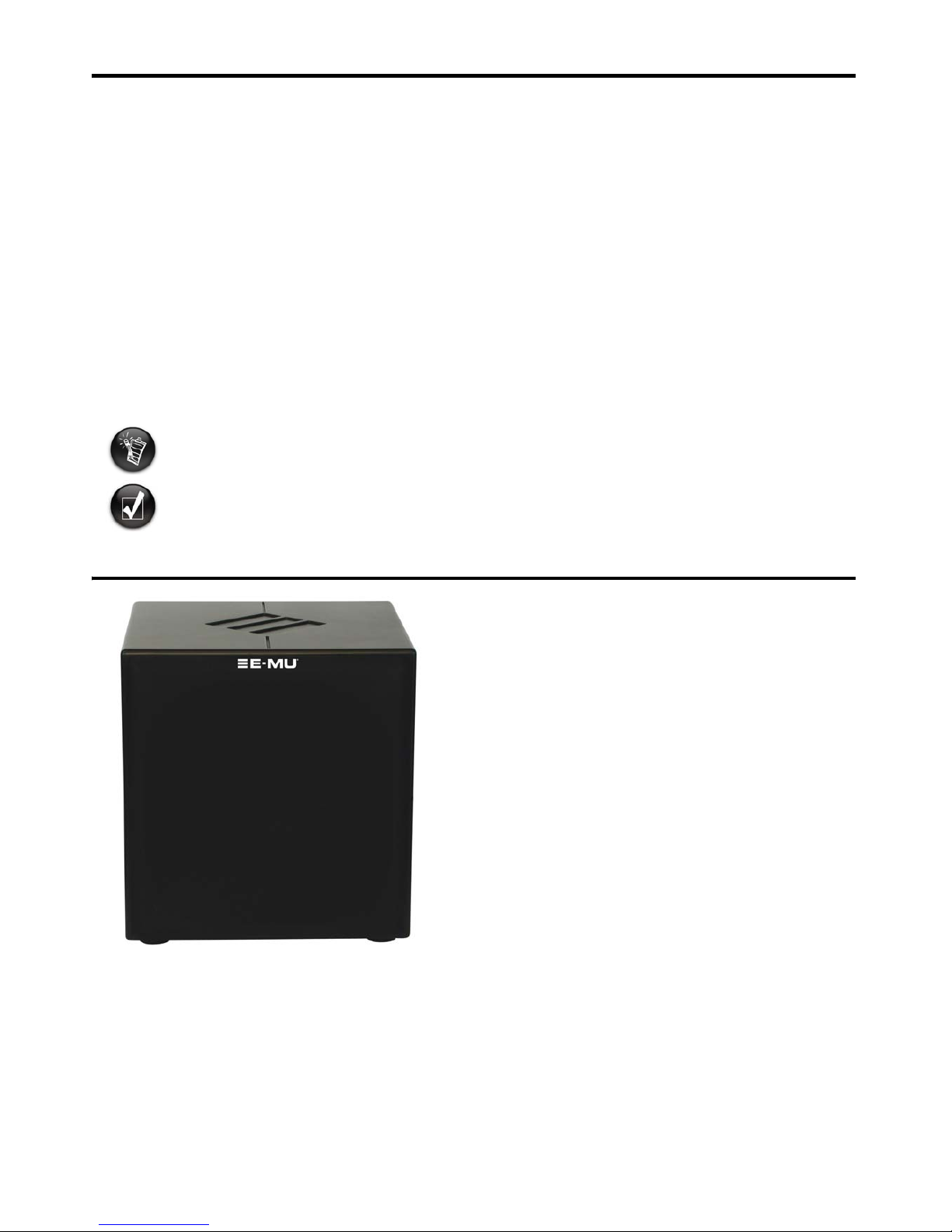
E-MU® PS12 Precision Subwoofer
Thank you for purchasing the E-MU PS12 Precision Subwoofer. This active reference subwoofer features a custom 200W
audiophile MOSFET amplifier, 12” polymer-laminate long-throw driver in a compact sealed cabinet designed to deliver
hyper-accurate audio reproduction for all your critical monitoring needs. From nuanced acoustic performances to extreme club
mixes, the PS12 delivers linear frequency response down to 22Hz. Whether used in conjunction with E-MU PM5 Precision
Monitors or other satellite speakers, the PS12’s professional features make it perfect for both stereo and surround applications.
These features include balanced and unbalanced inputs and outputs; high-pass, low-pass and subsonic filters; variable level and
phase controls; overload protection; auto standby mode; and a foot switch input that allows effortless bypassing of the subwoofer
and high-pass filter during mixdown.
This package includes:
• 1 x E-MU PS12 Precision Subwoofer
• 1 x Power Cord
• 1 x Owner's Manual
• 1 x Warranty and Support Information
Notes and tips
Items of special interest are presented in this document as notes and tips:
Contents
• Note. This highlights additional or important information about a feature.
• Tip. This tells you about shortcuts or hints relating to a feature.
Overview ........................................... 2
Unique Features ............................... 3
Plugging in Your Subwoofer ............. 3
Input and Output Connections ....... 4
Typical Setups ................................... 5
Positioning Your Subwoofer ............ 7
Tuning Your Subwoofer ................... 8
Technical Specifications ................ 10
Information in this document is subject to change without notice and does not represent a commitment on the part of E-MU
Systems, Inc. No part of this manual may be reproduced or transmitted in any form or by any means, electronic or mechanical,
including photocopying and recording, for any purpose without the written permission of E-MU Systems, Inc.
Version 1.0
April 2006
© 2006. E-MU Systems, Inc. All rights reserved. E-MU is a registered trademark of E-MU Systems, Inc. in the United States and in
other countries. The Creative logo is a registered trademark of Creative Technology Ltd. in the United States and in other countries.
All other logos, brand or product names are trademarks or registered trademarks of their respective holders and are hereby
recognized as such. All specifications are subject to change without notice. Use of this product is subject to a limited warranty. Actual
contents may differ slightly from those pictured.
Page 5
2
Overview
The E-MU PS12 Precision Subwoofer is a powered front-firing subwoofer with a 12” speaker driven by a custom 200W amplifier.
For creating the smoothest possible crossover between the subwoofer and your satellite speakers, the PS12 features fully
customizable filter controls, including a low-pass filter on the subwoofer signal and a high-pass filter on the satellite output signal.
Other key features include:
• Extremely compact sealed cabinet design
• Linear frequency response down to 22Hz
• Variable subwoofer Level and Phase control (0 to 180 degrees)
• Subsonic Rumble Filter
• Built-in Overload Protection
• Balanced and Unbalanced Inputs and Outputs
• Subwoofer bypass (satellite pass-through) footswitch input
• Automatic 15-minute low-power Standby mode
• Selectable 100-120V / 220-240V Operation
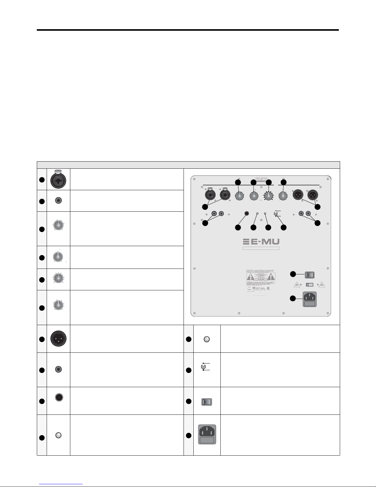
Controls
All the controls for the PS12 are located on the back panel. The following table describes each control:
Subwoofer Components
Balanced Inputs
Right and Left Neutrik® Combination XLR/TRS
balanced analog input connectors.
Unbalanced Inputs
Right and Left RCA unbalanced analog input
connectors.
Subwoofer Low-Pass Filter Frequency
Controls the low-pass filter cutoff frequency for
the signal being fed to the Subwoofer. 55Hz to
Flat (no filter).
Phase
Controls the phase of the signal being fed to the
subwoofer. 0 to 180 degrees.
Level
Controls the level of the signal being fed to the
subwoofer.
Satellite Output High-Pass Filter
Frequency
Controls the high-pass filter cutoff frequency for
the signal being fed to the satellite speakers. 40Hz
to 135Hz.
Balanced Satellite Outputs
Right and Left XLR balanced analog output
connectors.
High-Pass Filter Status LED
• Lights in green when the high-pass filter is active.
• Lights in red when the high-pass filter is bypassed
using the Switch or Foot Switch.
Unbalanced Satellite Outputs
Right and Left RCA unbalanced analog satellite
output connectors.
High-Pass Filter Status Switch
Normal: High-pass filter on (except when the Foot
Switch is used).
Off: High-pass filter is turned off and the full
unfiltered signal is sent to the satellite outputs.
Foot Switch Connector
¼” Latching Foot Switch connector for easy
bypassing of the subwoofer and high-pass filter.
* Foot Switch Not Included
ON/OFF Switch
Turns power to the subwoofer On or Off.
Subwoofer Status LED
• Lights in green when the subwoofer is active.
• Lights in red when subwoofer is muted (either
during standby mode or when muted by
footswitch).
Power Socket
• Disconnect the power adapter cable from the
power socket if you do not intend to use your
subwoofer for several days
• Make sure that the voltage rating of your speaker
matches the voltage standard of your country.
1
E
-MU PS12 Precision Subwoofer
INPUT VOLTAGE: 100V-120V 50/60HZ INPUT CURRENT: 2.5 A
INPUT VOLTAGE: 220V-240V 60/60HZ INPUT CURRENT:1.25A
MADE IN CHINA
2.5A 250V
100V-120
V
1.25A 250V
220V-240V
SUBWOOFER INPUTS SATELLITE OUTPUTS
RL RL
RL RL
LOWPASS
FREQ (Hz)
PHASE LEVEL HIGHPASS
FREQ (Hz)
FOOT
SWITCH
GREEN - ON
RED - BYPASS
HIGHPASSSUB
power
offon
voltage select
min max
90
0
180
40 135
55
100
120
60
80
55
60
100
120
80
flat
115
HIGHPASS
STATUS
OFF
NORMAL
1
2
3
4
5
6
7
8
9 10 1211
13
14
2
3
LOWPASS
FREQ (Hz)
55
60
100
120
80
flat
4
PHASE
90
0
180
5
LEVEL
min max
6
HIGHPASS
FREQ (Hz)
40 135
55
100
120
60
80
7
11
HIGHPASS
8 12
HIGHPASS
STATUS
OFF
NORMAL
9
FOOT
SWITCH
13
power
of
f
on
10
SUB
14
Page 6

3
Unique Features
This section describes some of the unique features of the PS12.
Sub-Sonic Rumble Filter
The Sub-sonic rumble filter stops unwanted inaudible bass frequencies from playing through your PS12. Some very low
frequencies, (such as those below 20Hz), although inaudible, can cause rumbling of the cabinet, and even rattling of objects in the
listening room. The PS12 automatically filters these unwanted low frequency sounds out, reducing noise caused by rumble, and
increasing amplifier efficiency in the audible range.
Overload Protection
The PS12’s built-in Overload Protection circuitry automatically engages when levels get too high, preventing potential damage to
the driver.
Foot Switch Input
The
¼”
Foot Switch input accepts all standard latching or latch-type foot switches. A Foot Switch allows you to bypass the
subwoofer and its high-pass filter circuitry.
Pressing the Foot Switch puts the subwoofer on mute, and sends the full audio signal to the satellite outputs. This is extremely
useful is you want to A-B your source audio with or without the subwoofer.
High-Pass Filter Bypass Switch
If you want to hear the full unfiltered signal through your satellite speakers without bypassing the PS12, flip this switch to OFF.
With the high-pass filter turned off, the signal coming out of the satellite outputs is identical to the signal going into the
subwoofer.
Automatic Standby Mode
If no signal comes through your subwoofer for approximately 15 minutes, the subwoofer automatically enters low-power Standby
mode, muting all sound coming out of the subwoofer. When the PS12 detects a signal, it becomes active again.
When the PS12 enters standby mode, the Subwoofer Status LED turns Red. When the PS12 resumes to normal mode, the
Subwoofer Status LED turns green.
Selectable Voltage Operation
The Voltage Select switch on the PS12 allows you to select between 100-120V and 220-240V operation.
Check that the appropriate voltage is selected before powering up your PS12 for the first time.
Plugging in Your Subwoofer
Before you plug your subwoofer in for the first time, make sure that the Voltage Select switch just above the power connector is
in the appropriate position in accordance to the power outlet you’re using.
Use the 115 Volt setting if you use AC power rated at 100-120 Volts (Most US power outlets).
Use the 230 Volt setting if you use AC power rated at 220-240 volts.
voltage select
115
voltage select
230
Page 7
4
Input and Output Connections
The PS12 includes balanced and unbalanced subwoofer inputs and satellite outputs.
Subwoofer Inputs
For each channel (Right and Left), your subwoofer features a combination XLR/TRS balanced analog input connector and an RCA
unbalanced analog input connector for connecting a wide variety of analog audio sources.
Satellite Outputs
For each channel (Right and Left), your subwoofer features an XLR balanced analog output connector and an RCA unbalanced
analog output connector for connecting your subwoofer to a pair of satellite speakers. The signal to these outputs comes directly
from subwoofer inputs after passing through the high-pass filter.
If you used the RCA inputs, you must use the RCA satellite outputs in order to use subwoofer/HPF bypass mode.
• Before connecting your subwoofer, make sure that the level is
turned fully counterclockwise.
• Do not connect more than one audio input device to your
subwoofer at any one time, as this will cause the mixing of
input signals and result in unwanted noise.
You may hear a thump from your speaker when you turn your
audio setup on and off. To prevent this, make sure that your
speakers are the last devices in your setup to be turned on and
the first devices in your setup to be turned off.
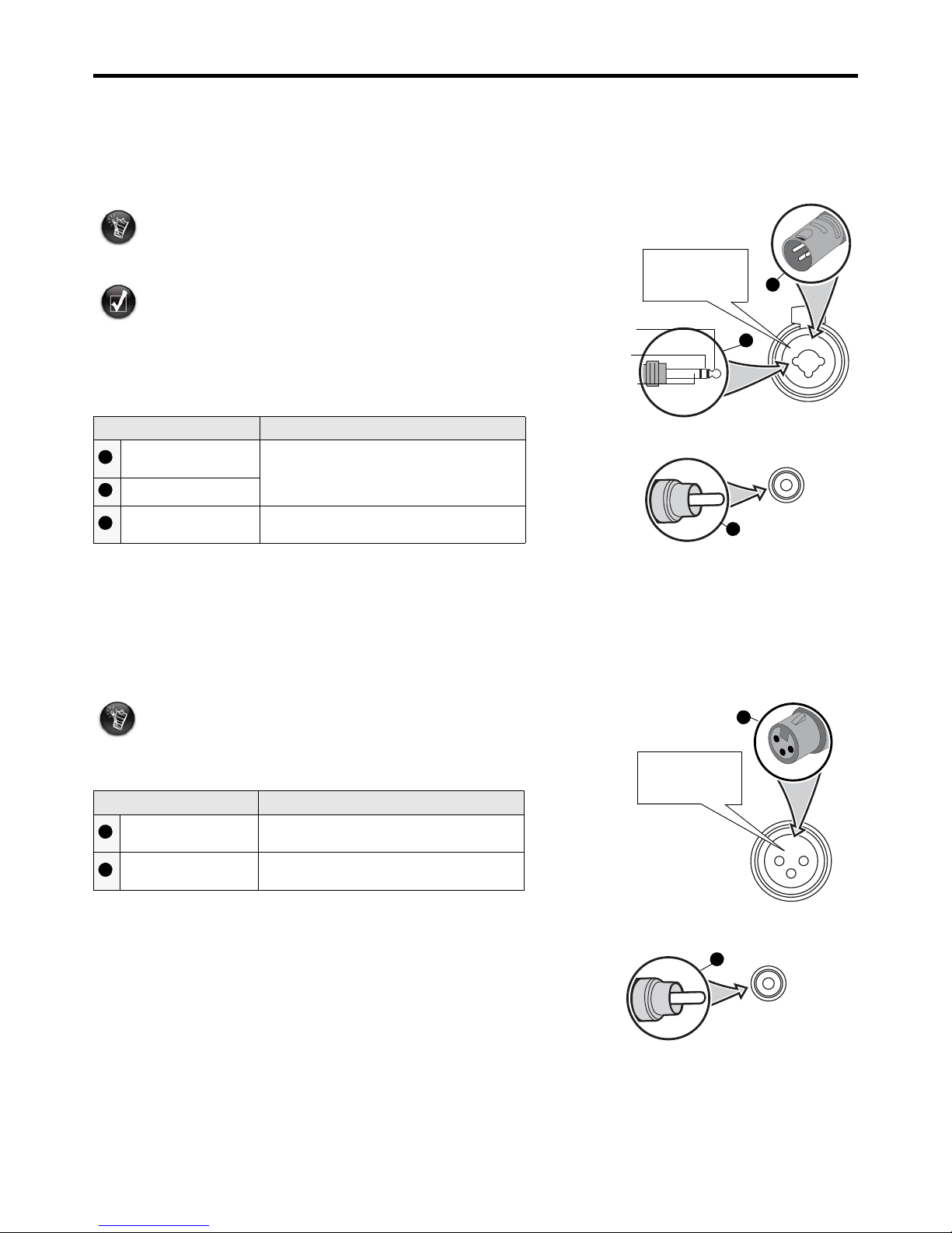
Connector Connection
Balanced ¼” TRS or
Unbalanced ¼” TS
Connect to the combination XLR/TRS
balanced analog input connector
Balanced XLR male
Unbalanced RCA
Connects to the RCA unbalanced analog input
connector
Before connecting satellite speakers, make sure that
the level controls on the speakers are turned all the
way down.
Connector Connection
Balanced XLR female
Connects to the XLR balanced analog output
connector
Unbalanced RCA
Connects to the RCA unbalanced analog
output connector
r
r
12
3
1 = Ground/Shield
2 = Hot (+)
3 = Cold (-)
Tip = Hot (+)
Ring = Cold (-)
Sleeve = Ground/Shield
1
2
3
1
2
3
12
3
r
r
1 = Ground/Shield
2 = Hot (+)
3 = Cold (-)
1
2
1
2
Page 8

5
Typical Setups
This section shows some typical configurations for your PS12, including a single subwoofer setup, a dual subwoofer setup, and a
single subwoofer surround setup.
Single Subwoofer Setup
The most common single subwoofer configuration is as shown below, where the audio source’s right and left line outputs are
connected to the right and left inputs of the subwoofer. The right and left satellite outputs are then connected to powered
monitor speakers.
If you use passive monitor speakers, you’ll need to run the satellite
outputs to a power amplifier, which in turn feeds your passive speakers.
-
MODEL NO: PS1
2
REPLACE FUSE AS MARKED
2
.5A 250V
V-
120V220V-240V
SUBWOOFER INPUTS SATELLITE OUTPUTS
RL RL
RL RL
LOWPASS
FREQ (Hz)
PHASE LEVEL HIGHPASS
FREQ (Hz)
FOOT
SWITCH
GREEN - ON
RED - BYPASS
HIGHPASSSUB
power
offon
voltage select
min max
90
0
1
80
40 135
55
100
1
20
60
80
55
60
1
00
120
80
flat
115
HIGHPASS
STATUS
OFF
NORMAL
Powered Monitor
Left Right
Powered Monitor
Mixing Console
Page 9
6
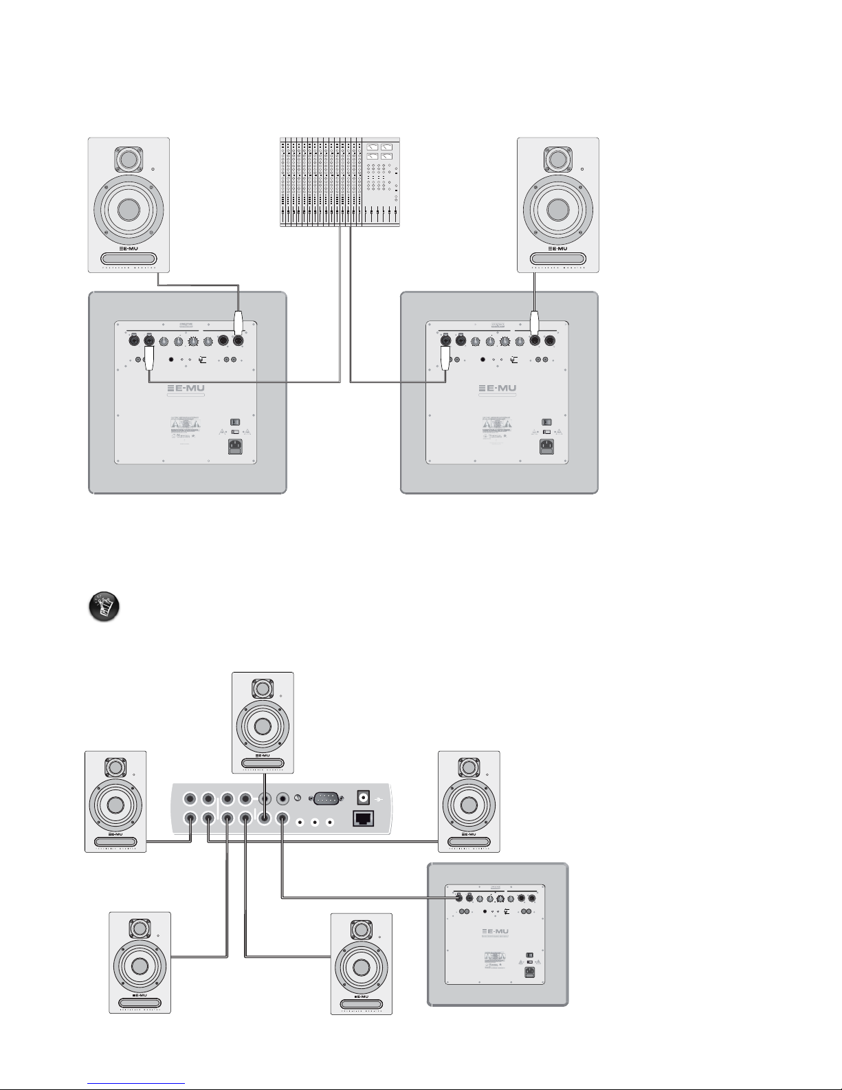
Stereo Subwoofer Setup
If you use two subwoofers, it’s typical to send the left output from your mixing console to one subwoofer, and the right output
from your console to the other subwoofer. Each subwoofer feeds an individual monitor speaker. This setup is shown below:
Single Subwoofer Surround Setup
To set up your subwoofer in a surround configuration, run the Subwoofer Line Out of your surround receiver, sound card, or
other device to either the right or left input of your subwoofer.
The following diagram illustrates how you would set up surround with an E-MU 1616*, five powered satellite speakers, and a PS12.
Make sure the Subwoofer Output you use on your surround device is line-level
(not an amplified signal).
-MU PS12 Precision Subwoofer
DEL NO: PS12
EPLACE FUSE AS MARKE
D
DESIGNED IN THE U.S.A
.
2.5A
25
0V
-
120V
220V-240V
SUBWOOFER INPUTS SATELLITE OUTPUTS
RL RL
RL RL
LOWPASS
FREQ (Hz)
PHASE LEVEL HIGHPASS
FREQ (Hz)
FOOT
SWITCH
GREEN - ON
RED - BYPASS
HIGHPASSSUB
power
offon
voltage select
min max
90
0
1
80
40 135
55
100
1
20
60
80
55
60
1
00
120
80
flat
115
HIGHPASS
STATUS
OFF
NORMAL
-MU PS12 Precision Subwoofe
r
EPLACE FUSE AS MARKE
D
-
120V
220V-240V
SUBWOOFER INPUTS SATELLITE OUTPUTS
RL RL
RL RL
LOWPASS
FREQ (Hz)
PHASE LEVEL HIGHPASS
FREQ (Hz)
FOOT
SWITCH
GREEN - ON
RED - BYPASS
HIGHPASSSUB
power
offon
voltage select
min max
90
0
1
80
40 135
55
100
1
20
60
80
55
60
1
00
120
80
flat
115
HIGHPASS
STATUS
OFF
NORMAL
Powered Monitor
Left Right
Powered MonitorMixing Console
EDI
In
1L
1R
2L
2R
3L
3R
2L
2R
Out
1L
1R
Phono
Gnd
2L
2R
1
2
Out
48VDC
+
-
MIDI Cable
3
DESIGNED IN THE U.S.A.
IN
CHINA
1.25A 250V
2
20V-240V
SUBWOOFER INPUTS SATELLITE OUTPUTS
RL RL
RL RL
LOWPASS
FREQ (Hz)
PHASE LEVEL HIGHPASS
FREQ (Hz)
FOOT
SWITCH
GREEN - ON
RED - BYPASS
HIGHPASSSUB
power
offon
voltage select
min max
90
0
1
80
40 135
55
100
1
20
60
80
55
60
1
00
120
80
flat
115
HIGHPASS
STATUS
OFF
NORMAL
Center
Front Left Front Right
Rear Left
Rear Right
* Select the 5.1 DVD Playback
Patchmix DSP session
Page 10
7
Positioning Your Subwoofer
Low-frequency waves (especially those below 100Hz) tend to be omni-directional, so unlike your main speakers, a subwoofer can
successfully be placed in many different parts of the room, not just in front of the listener.
However, many factors, such as room shape and wall material, can significantly affect performance. Therefore, placement of your
subwoofer is worth thoroughly investigating to achieve the maximum performance from your PS12. If you have an untreated
room, and don’t have the resources to measure the bass response of your listening area, your best bet is going to be
experimentation.
Walls and Corners
While it might seem like placing your subwoofer near a wall, or in a corner is a bad idea, sometimes it turns out to be an ideal
location, especially if your room consists of four non-treated walls.
Corner placement reinforces the direct sound of the subwoofer, and can sometimes smooth the inevitable standing waves that
occur among low frequencies in a non-treated room.
Center Placement
Some people prefer to place a single subwoofer between stereo satellite speakers. If you do so, it’s best to place it close to a wall.
Subwoofers tend to perform at their worst in wide open spaces.
Stereo Subwoofers
If you’re using two PS12’s in stereo, you’ll probably want to place each subwoofer near it’s respective satellite speaker.
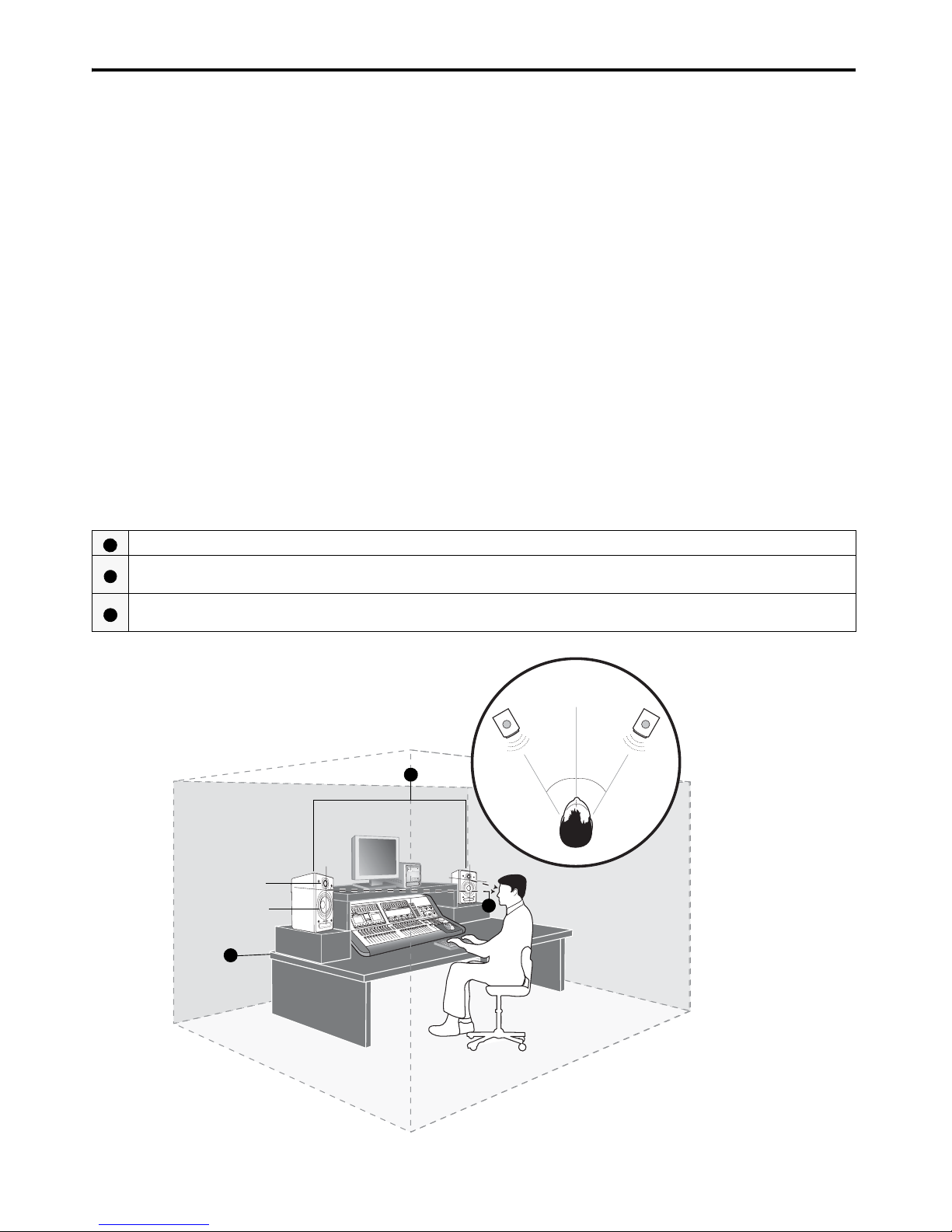
Satellite Speaker Placement
Your satellite speakers should already be properly placed and set at a reasonable listening level before attempting to tune the
PS12. If they aren’t refer to the documentation that came with your speakers. The basic ideas regarding placement should include
the following:
Place your speakers on a flat, stable surface to minimize vibration.
Position your speakers at the same height, and maintain the same speaker-to-wall and speaker-to-listener distance for both
speakers.
The acoustic axis of each speaker falls on the mid-point between the speaker’s high-frequency driver and low-frequency driver.
Position your speakers such that the acoustic axes are at the same height as your ears.
1
2
3
L
30°
30°
R
High-frequency driver
Low-frequency driver
1
2
3
Page 11
8
Tuning Your Subwoofer
A subwoofer is designed to handle the low frequency signals that nearfield monitors cannot handle. Since most nearfield monitors
cannot handle frequencies below about 60Hz, you’ll want the PS12 to handle any frequencies below that. In fact, depending on
how your satellites perform at low frequencies, you might want your subwoofer to be responsible for frequencies as high as 80 100Hz.
The Crossover
The point at which your nearfield monitors stop handling the audio signal, and the PS12 takes over is called the crossover
frequency. The idea when setting up a crossover is to create a seamless, inaudible transition between your subwoofer and
attached satellite speakers. You should set up your subwoofer in the following order:
1. Position and tune your satellite speakers
2. Position and set the subwoofer level.
3. Set up the crossover frequency
4. Check the phase relationship between the subwoofer and the satellite speakers.
A good audio source for setting up the PS12 is a sine wave that sweeps slowly accross the crossover point. E-MU has sine wave
sweeps available for download at the “software and manuals" page at www.emu.com/support. Adjust the output of your audio
source to a comfortable volume, and begin adjusting the level of the PS12.
Level
The level knob controls the level of the subwoofer’s amplifier, thus only affecting the volume of the subwoofer itself. Turn the
knob clockwise until the PS12’s sound is present, the low frequencies begin to seem filled out. This should be enough to hear the
subwoofer low frequencies, but not so much that the PS12 stands out above the satellite speakers— the idea is to match the
PS12’s volume with that of your satellite speakers. Don’t turn up the PS12 so much that it’s easily audible as an individual speaker.
Remember, you’re trying to blend the subwoofer and your satellites to create a full-range monitoring system.
Subwoofer Low-Pass Filter (LPF) and Satellite Output High-Pass Filter (HPF)
Now, use the Low-Pass Frequency Knob to adjust the low-pass filter for the sound coming out of your subwoofer. This filter
constitutes the lower half of the crossover, and ranges in frequencies from 55Hz to Flat (no filter). The crossover frequency you
choose for the LPF will depend on the performance of your satellite speakers.
The literature for you satellite speakers should contain information about the speakers’ low-frequency cutoff. Use that
information to determine where you want your crossover frequency to occur, and set your LPF knob accordingly. Your satellite
speakers may have an adjustable roll-off, which can potentially add to the overall acoustic slope of the high-pass filter. Set the
roll-off on your satellite speakers to its lowest frequency. It's best to have the satellites set for full-range operation whenever using
the PS12.
At the same time, use the High-Pass Frequency Knob to adjust the HPF for the sound passing through the subwoofer to the
satellite speakers. This filter ranges in frequencies from 40Hz to 135Hz. You’re probably best off starting with the same frequency
as the LPF.
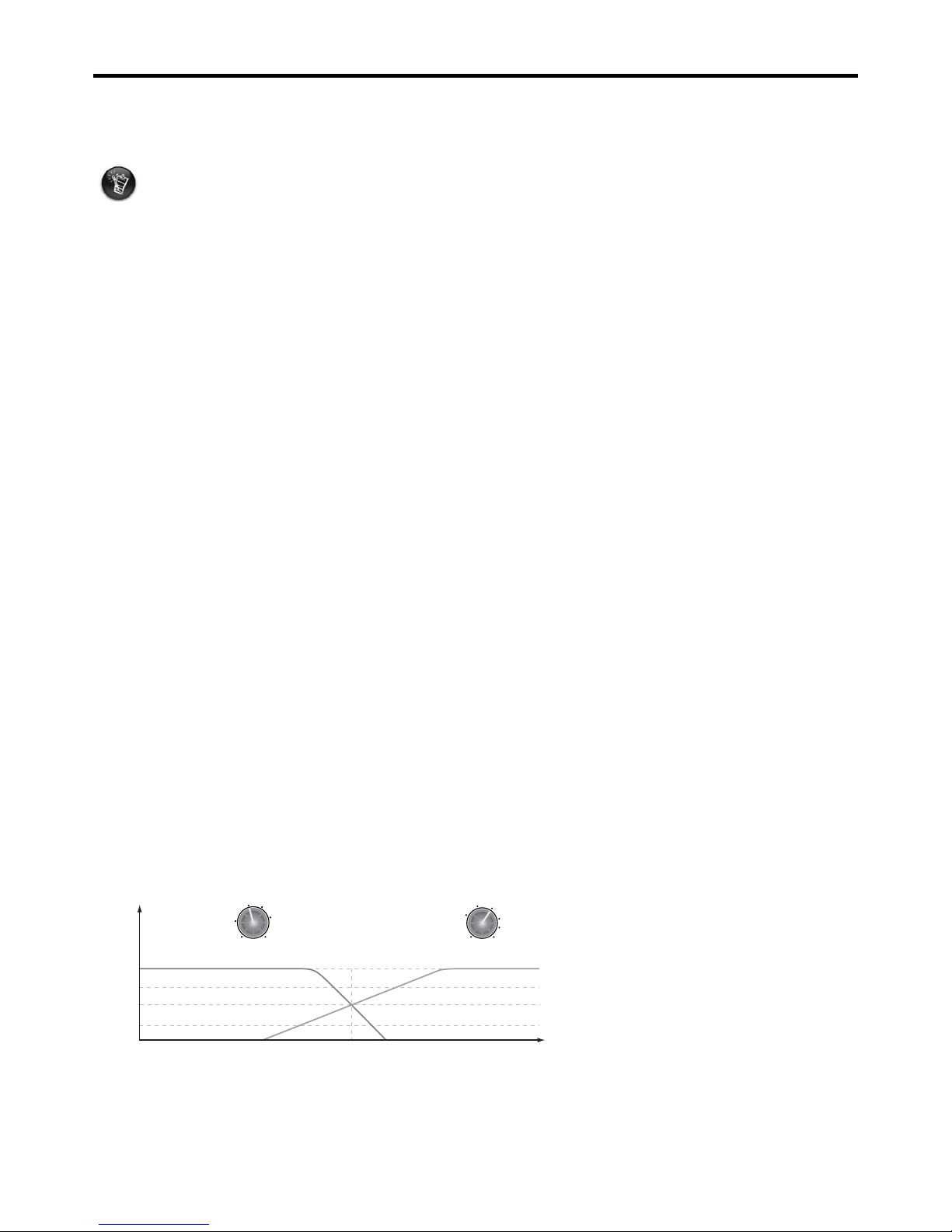
Let’s say you’ve set your LPF and HPF each to 80Hz (a common crossover frequency, and a good place to start). You’ll have both
speakers playing the crossover 80Hz at the same time— one fading in while the other fades out. Your crossover would look
something like this:
What you’re aiming for is a smooth transition between frequencies handled by your satellite speakers and those by the PS12. If
you’re listening to a sweeping wave sound, try to eliminate any boosts or cuts that occur when the sweep reaches the crossover
frequencies. You can do this by increasing or decreasing the amount of crossfade you have between the two filters.
This section assumes you’ve already adjusted the positioning and levels of your satellite speakers.
For advice on setting up your satellite speakers, refer to the documentation that came with them,
and/or the information on the previous page.
-3
0
Amplitude (dB)
-6
-10
Frequency (Hz)
80
LOWPASS
FREQ (Hz)
55
60
100
120
80
flat
HIGHPASS
FREQ (Hz)
40 135
55
100
120
60
80
The settings on the knobs represent
where the filter has attenuated the
volume to -6dB.
A setting of 80Hz for both LP and HP
filters means that the subwoofer and
satellites are both at -6dB at 80Hz.
Page 12
9
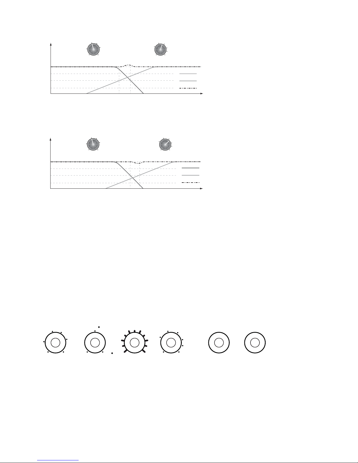
For example, if you set the LPF to 80Hz and the HPF to 75Hz, you will hear sound from both speakers between 75Hz and 80Hz.
However, this might cause an audible boost in that frequency range.
Set the LPF to 80Hz and the HPF to 85Hz, and there might be a point somewhere between 80Hz and 85Hz where neither
speaker is playing, causing a dip when you listen to your filter sweep.
Experiment with the HPF knob until you find the right balance where there is neither a dip, nor a boost near the crossover
frequency. It is important remember that the ideal settings for these knobs will vary depending upon room size and shape, where
you place the PS12, and the performance of your satellite speakers.
Phase
This controls the phase of the signal going to the subwoofer amplifier, thus changing the relationship between the subwoofer
signal and the satellite output signal.
Phase cancellation occurs when two identical signals reach your ears at different time. Depending on your filter settings, there will
likely be a small range of frequencies (near the crossover frequency) playing through both the subwoofer and attached satellite
speakers.
Unless the distance between the subwoofer and your ears is identical to the distance between the satellite speakers and your
ears, these frequencies will be slightly out of phase with each other. You can use the variable phase control to change the phase of
the subwoofer output from 0 to 180 degrees to compensate for this disparity.
Remember Your Settings
Once you find the optimum settings for your PS12, you can mark them on the following template for future reference. Two extra
knobs are provided for your satellite speakers.
-3
0
Amplitude (dB)
-6
-10
Frequency (Hz)
8075
LOWPASS
FREQ (Hz)
55
60
100
120
80
flat
HIGHPASS
FREQ (Hz)
40 135
55
100
120
60
80
Low-Pass
High-Pass
Combined
Too much overlap between
the satellites and the
subwoofer causes a boost in
the combined signal near the
HPF and LPF frequencies.
-3
0
Amplitude (dB)
-6
-10
Frequency (Hz)
80 85
LOWPASS
FREQ (Hz)
55
60
100
120
80
flat
HIGHPASS
FREQ (Hz)
40 135
55
100
120
60
80
Low-Pass
High-Pass
Combined
Too little overlap between the
satellites and the subwoofer
causes a dip in the combined
signal between the HPF and LPF
frequencies.
PHASE
90
0
18 0
LEVEL
min max
HIGHPASS
FREQ (Hz)
40 135
55
10 0
12 0
60
80
LOWPASS
FREQ (Hz)
55
60
10 0
12 0
80
flat
Satellite L Satellite R
Page 13

10
Technical Specifications
* Foot Switch not included
General
Ty p e
Front firing, acoustic suspension active reference subwoofer
Frequency Response
22Hz ~ 135Hz (±2.5dB), 30Hz - 100Hz (± 1.5dB)
Maximum Sound Pressure Level, short term ≥
103dB SPL @1m @ 60Hz
Driver
Polymer-Laminated Cone with Butyl-rubber surround
12" Diameter Long-Throw woofer with 50mm high temperature voice coil
Size: 305mm (12”)
Dimensions
Height: 385mm (15.1")
Width: 362mm (14.2")
Depth: 390mm (15.3")
Weight
19.5kg (43lbs)
Power
Input Voltage: 100 - 120V~50/60Hz Input Current: 2.5A
Input Voltage: 220 - 240V~50/60Hz Input Current: 1.25A
Fuse
100-120V: 2.5A/250V
220-240V: 1.25A/250V
Connections
Inputs
(2) Balanced Neutrik® Combination XLR -
¼”
(2) Unbalanced RCA
Satellite Outputs
(2) Balanced XLR
(2) Unbalanced RCA
Subwoofer/High-Pass Bypass Foot Switch *
¼” Foot Switch input
Crossover Network
Sub-Sonic Rumble Filter
15Hz @ 12dB/Octave
Low-Pass Filter (to subwoofer)
Variable frequency Linkwitz-Riley 4th order (55Hz ~ 135Hz)
High-Pass Filter (to satellite outputs)
Variable frequency Linkwitz-Riley 2nd order (40Hz ~ 135Hz)
Input impedance
Balanced: 20K ohms
Unbalanced: 100K ohms
Amplifier
Ty p e
Custom discrete MOSFET
Power
200W RMS into 4 ohms Continuous
Signal-to-Noise Ratio, referred to full output
> 102dB A-weighted
Distortion
THD < 0.1%
Page 14

i
INFORMATIONS DE SÉCURITÉ — NORMES
Les chapitres qui suivent contiennent des informations qui s’appliquent à divers pays :
Remarques pour les USA
Réglementation fédérale FCC, alinéa 15 : Ce
produit a été testé et répond aux normes sur
les équipements numériques de Classe B, selon
l’alinéa 15 des régulations fédérales FCC. Ces
normes offrent une protection raisonnable
contre les interférences en environnement
résidentiel. Cet appareil génère, utilise et peut
émettre des fréquences radio, et; s’il n’est pas
installé et utilisé selon les instructions, peut
causer des interférences nuisibles aux
communications radio. Cela dit, ces remarques
ne constituent pas une garantie contre toute
apparition d’interférences en fonction de
l’installation. Si cet appareil cause des
interférences aux réceptions radio ou
télévision, ce que vous pouvez déterminer en
plaçant l’appareil sous/hors tension, essayez les
solutions suivantes :
U Réorientez ou déplacez l’antenne de
réception.
U Éloignez l’appareil du récepteur.
U Connectez l’appareil sur une ligne secteur
différente de celle du récepteur.
U Consultez le revendeur ou un technicien
radio/ TV.
ATTENTION : Pour répondre aux normes
sur les équipements numériques de Classe B,
alinéa 15 de la réglementation fédérale FCC,
cet appareil doit être installé avec des
équipements certifiés et répondant aux
normes de la Classe B.
Tous les câbles utilisés pour connecter
l’ordinateur et les périphériques doivent être
blindés et mis à la masse. L’utilisation
d’équipements qui ne répondent pas à ces
normes ou l’utilisation de câbles non blindés
peut générer des interférences radio ou
télévision.
Modifications
Les changements ou modifications non
expressément approuvés par la garantie de ce
produit peuvent annuler vos droits à utiliser
cet appareil.
Remarques pour Canada
This apparatus complies with the Class B limits for
radio interference as specified in the Canadian
Department of Communications Radio
Interference Regulations.
Cet appareil est conforme aux normes de Classe
“B” sur les interférences radio, telles que spécifiées
par le Ministère Canadien des Communications
dans les réglementations sur les interférences
radio.
Remarque importante
Ce produit possède un numéro de série. Notez-le
et conservez-le pour toute consultation ultérieure.
MISE EN GARDE
Évitez toute utilisation de ces enceintes à des
niveaux sonores élevés !
Si les enceintes ne produisent aucun son, laissez le
niveau sur un réglage très faible lorsque vous
essayez de rétablir le son. Ceci évite toute
utilisation accidentelle à des niveaux sonores
dangereux.
Normes européennes
Ce produit est conforme aux normes suivantes :
Directive EMC 89/336/EEC, amendements 92/31/
EEC et 93/68/EEC.
Les produits alimentés par secteur pour le marché
européen répondent aux directives LVD 73/23/
EEC, amendement 93/68/EEC.
DÉCLARATION DE CONFORMITÉ
Fabriquant Importateur EU
E-MU Systems, Inc.
1500 Green Hills Road,
Suite 101
Scotts Valley, CA. 96066
United States
Creative Labs Ireland Ltd.
Ballycoolin Business Park
Blanchardstown, Dublin 15
IRELAND
déclare sous sa propre responsabilité que le produit
Nom commercial : E-MU Systems
Références du modèle : PS12/EM9100
a été testé selon les alinéas de la norme CI SPR13 et répond aux
normes suivantes :
EMI/EMC : CISPR 13 : 2003, FCC alinéa 15 sous-alinéa B
Compatible avec la norme canadienne ICES-003 sur les équipements de
Classe B
Cet appareil est compatible avec l’alinéa 15 des réglementatioss fédérales.
L’utilisation est sujette aux deux conditions suivantes :
(1) Cet appareil ne doit pas générer d’interférence
(2) Cet appareil doit accepter toutes les interférences reçues, dont les
interférences pouvant causer un fonctionnement instable.
Responsable de la normalisation
E-MU Systems, Inc.
27 avril 2006
Responsable de la normalisation
E-MU Systems, Inc.
27 avril 2006
Responsable de la normalisation
Creative Labs Ireland
27 avril 2006
Page 15

ii
MISES EN GARDE IMPORTANTES SUR LA SÉCURITÉ
CONSIGNES DE SÉCURITÉ
• Lisez les intstructions.
• Conservez les instructions.
• Respectez les mises en en garde.
• Suivez les instructions.
• Ne pas utiliser ce produit près d’eau.
• Utilisez uniquement un tissu sec pour le
nettoyage.
• Veillez à ne pas boucher ou obstruer les ouïes
de ventilation. Suivez toujours les instructions
de fabricant.
• Ne pas placer ce produit près d’une source
de chaleur telle qu’un radiateur, poêle, et
autres produits (dont les amplificateurs de
puissance) générant de la chaleur.
• Ne jamais déconnecter la terre de la fiche.
Les fiches avec secteur comportent trois
bornes. La borne centrale correspond à la
terre et garantit la sécurité de l’utilisateur. Si
la fiche fournie ne correspond pas au format
de votre prise secteur murale, consultez un
électricien et faites remplacer la prise murale.
• Placez le cordon secteur de façon à éviter
tout dommage (notamment en évitant que les
personnes ne marchent dessus, ou en évitant
tout pincement du cordon). Protégez le
cordon près de sa sortie de l’appareil et près
de la fiche.
• Ne pas utiliser de fixations ou accessoires
non recommandés par fabricant, car ils
peuvent être source d’accident.
• Déconnectez l’appareil du secteur en
présence d’orage ou si vous ne l’utilisez pas
pendant longtemps. Vous éviterez ainsi tout
risque de dommage au produit par
surtension.
• Toutes les réparations doivent être
éffectuées par un personnel qualifié. Faites
réparer lorsque le cordon ou la fiche secteur
est endommagé, un objet ou un liquide s’est
infiltré dans le produit, le produit a été
exposé à la pluie ou à un liquide, le produit ne
fonctionne pas normalement lorsque vous
suivez les instructions d’utilisation, le produit
fonctionne anormalement, le produit est
tombé ou est endommagé.
MISES EN GARDE :
POUR RÉDUIRE LES RISQUES D’ÉLECTROCUTION
OU D’INCENDIE :
U NE PAS EXPOSER CET APPAREIL À LA PLUIE
OU À L’HUMIDITÉ.
U NE PAS EXPOSER CET APPAREIL À DES
SOURCES LIQUIDES ET NE PAS POSER UN
OBJET CONTENANT UN LIQUIDE — VASE,
PAR EXEMPLE — SUR L’APPAREIL.
La fiche secteur et l’interrupteur secteur permettent
de déconnecter l’appareil du secteur. L’enceinte doit
être placée près d’une prise secteur facilement
accessible et en bon état de fonctionnement.
FLAMMES - aucune source de flamme, telle que les bougies
allumées, ne devrait être placée sur l'appareil.
ALIMENTATION - Ce produit a été conçu pour être
alimenté par une tension et une fréquence secteur spécifiées
sur l’adaptateur secteur. L’utilisation d’une tension et/ou
d’une fréquence secteur autre que celle indiquée entraîne
des risques dont vous seul êtes responsable. Contactez
votre fournisseur d’électricité si vous avez des questions sur
la tension et la fréquence électrique de votre zone
géographique.
SURCHARGE - Veillez à ne pas surcharger les prises
secteur, les rallonges, les prises multiples ou les circuits
d’alimentation internes, car ceci constitue un risque
d’incendie ou d’électrocution.
INFILTRATION D’OBJET ET DE LIQUIDE - Ne jamais
insérer d’objet dans les ouvertures du produit — ceci
constitue un risque d’incendie, d’électrocution ou de
dommage. Ne jamais renverser un liquide sur le produit.
RÉPARATIONS - N’essayez pas de réparer vous-même le
produit. Confiez toutes les réparations à un personnel
compétent et qualifié.
PLACEMENT - Placez le produit sur une surface stable ou un
support recommandé, ou vendu avec le produit. Dans le cas
contraire, le produit peut chuter et blesser quelqu’un, ou
s’endommager. Suivez les instructions du fabriquant pour le
montage du produit.
PIÈCES DE RECHANGE - Lorsque vous faites remplacer des
pièces, assurez-vous que le technicien utilise les pièces de
rechange spécifiées par fabricant, ou par des pièces dont les
caractéristiques sont identiques à celles des pièces d’origine.
Les substitutions non agréées peuvent être source
d’incendie, d’électrocution, ou autre.
CONTRÔLE DE SÉCURITÉ - Après avoir fait réparer le
produit, demandez au réparateur de vérifier la sécurité de
l’appareil et que celui-ci fonctionne correctement.
L’éclair dans le triangle équilatéral prévient l’utilisateur que l’appareil
contient des tensions électriques dangereuses, d’amplitude suffisante à
constituer des risques d’électrocution aux personnes.
WAR NING
DO NOT OPEN
TO PREVENT THE RISK OF ELECTRIC SHOCK, DO NOT REMOVE SPEAKER
COVERS (OR BACKS). NO USER-SERVICEABLE PARTS INSIDE. REFER
SERVICING TO QUALIFIED SERVICE PERSONNEL.
Le point d’exclamation dans le triangle équilatéral prévient l’utilisateur de la
présence d’instructions d’utilisation et de maintenance importantes dans le
manuel qui accompagne ce produit.
MISE EN GARDE
NE PAS OUVRIR
POUR EVITER TOUT RISQUE D’ÉLECTROCUTION, NE PAS OUVRIR
L’ENCEINTE. AUCUN ENTRETIEN DES PIÈCES INTERNES N’EST REQUIS.
TOUTES LES RÉPARATIONS DOIVENT ÊTRE ÉFFECTUÉES PAR UN PERSONNEL
QUALIFIÉ.
CAUTION:
TO PREVENT THE RISK OF ELECTRIC SHOCK, MATCH WIDE BLADE OF PLUG
TO WIDE SLOT. INSERT CAREFULLY.
ATTENTION:
POUR EVITER LES RISUQES D’ÉLECTROCUTION, INTRODUIRE LA LAME LA
PLUS LARGE DE LA FICHE DANS LA BORNE CORRESPONDANTE DE LA PRISE
ET POUSSER JUSQU AU FOND.
REMARQUE IMPORTANTE :
Ce produit possède un numéro de série. Notez ce numéro de série et conservez-le
dans un lieu sûr pour toute référence ultérieure.
LISEZ ET RESPECTEZ LES CONSIGNES DE SÉCURITÉ SÉRI-
GRAPHIÉES À L’ARRIÈRE DE L’ENCEINTE
Ce symbole indique que ce produit ne peut pas être recyclé comme déchet
ménager. En veillant à vous débarrasser correctement de ce produit, vous
aiderez à protéger l’environnement. Pour obtenir de plus amples renseignements
sur le recyclage de ce produit, contactez les autorités locales, votre centre de
recyclage ou votre revendeur.
Page 16

1
E-MU® PS12 - Subwoofer de précision
Merci d’avoir choisi ce Subwoofer de précision E-MU PS12. Ce Subwoofer de référence dispose d’un amplificateur à transistors
MOSFET d’une puissance de 200 Watts conçu spécialement pour les audiophiles, d’un Woofer longue portée de 30 cm
(12 pouces) avec membrane en polymère stratifié et d’un baffle fermé de format compact. Sa conception assure une reproduction
extrêmement fidèle pouvant répondre à tous les besoins en matière d’écoute de précision. En effet, le PS12 offre une réponse en
fréquence linéaire (jusqu’à 22 Hz), permettant de reproduire aussi bien les nuances des morceaux acoustiques que celles des
morceaux de musique Dance. Qu’il soit utilisé avec les moniteurs de précision E-MU PM5 ou des enceintes satellites, le PS12 met
à votre disposition plusieurs fonctions professionnelles pour les applications stéréo et Surround, dont des entrées/sorties
symétriques et asymétriques, des filtres passe-haut, passe-bas et subsoniques, des réglages de niveau et de phase, un circuit de
protection contre les surcharges, une fonction de mise en veille automatique et un connecteur pour pédalier permettant de
désactiver rapidement le Subwoofer et le filtre passe-haut pendant le mixage.
Éléments fournis :
• Un Subwoofer de précision E-MU PS12
• Un cordon secteur
• Un mode d’emploi
• Une carte de garantie avec informations complémentaires
Remarques et astuces
Les éléments qui sont d’un intérêt particulier sont présentés sous forme de remarques et d’astuces :
Table des matières
• Remarque. Les remarques donnent des informations supplémentaires ou importantes sur les
fonctions.
• Astuce. Les astuces offrent des simplifications ou des conseils sur les fonctions.
Présentation ...................................... 2
Caractéristiques novatrices ............. 3
Connexion de votre Subwoofer....... 3
Connecteurs d’entrée et de sortie . 4
Configurations type .......................... 5
Positionnement du Subwoofer ........ 7
Configuration du Subwoofer ........... 8
Caractéristiques techniques ......... 10
Les informations contenues dans ce document peuvent être modifiées sans préavis et ne représentent aucun engagement de la part
d’E-MU Systems, Inc. Aucune partie de ce document ne peut être reproduite, transmise ou utilisée sous aucune forme ou par
quelque procédé que ce soit, électronique ou mécanique, ce qui comprend les photocopies et les enregistrements, sans la permission
écrite d’E-MU Systems, Inc.
Version 1.0
Avril 2006
© 2006. E-MU Systems, Inc. Tous droits réservés. E-MU est une marque déposée d’E-MU Systems, Inc. dans les USA et les autres
pays. Le logo Creative est une marque déposée de Creative Technology Ltd. dans les USA et les autres pays. Tous les autres logos,
marques et noms de produits sont la propriété de leur détenteur respectif. Toutes les informations peuvent être modifiées sans
préavis. L’utilisation de ce produit est sujet à une garantie limitée. Le produit peut être légèrement différent des illustrations. Distribué
par E-MU Systems, Inc., Scotts Valley, CA 95066.
Page 17

2
Présentation
Les Subwoofers E-MU PS12 sont des Subwoofers de précision actifs à diffusion frontale munis d’un Woofer de 3 cm (12 pouces)
alimenté par un amplificateur de 200 Watts de conception spéciale. Afin d’assurer une répartition de fréquences aussi homogène
que possible entre le Subwoofer et les satellites, les PS12 sont pourvus de filtres réglables, dont un filtre passe-bas pour le signal
du Subwoofer et un filtre passe-haut pour le signal de la sortie satellite.
Voici les autres caractéristiques principales :
• Baffle clos extrêmement compact
• Réponse en fréquence linéaire jusqu’à 22 Hz
• Réglages de niveau et de phase (0 à 180 degrés) du Subwoofer
• Filtre subsonique servant à éliminer les basses fréquences inutiles
• Circuit de protection contre les surcharges intégré
• Entrées et sorties symétriques et asymétriques
• Connecteur pour pédalier, permettant de désactiver le Subwoofer et d’utiliser le Pass-Through pour les satellites
• Mode de mise en veille (faible consommation) activé automatiquement après 15 minutes d’inutilisation
• Sélecteur de tension 100-120 V / 220-240 V
Réglages
Tous les réglages des PS12 se trouvent en face arrière. Le tableau ci-dessous présente chacun d’entre eux :
Composants du Subwoofer
Entrées symétriques analogiques
Connecteurs Neutrik® hybrides
(XLR/Jack 6,35 mm) droit et gauche.
Entrées analogiques asymétriques
Connecteurs RCA droit et gauche.
ueu
Réglage de fréquence du filtre passe-bas
Détermine la fréquence de coupure du filtre
passe-bas affectant le signal acheminé au Sub.
Plage de réglage : 55 Hz à Flat (filtre désactivé).
Réglage de phase
Détermine la phase du signal acheminé au
Subwoofer. Plage de réglage : de 0 à 180 degrés.
Réglage de niveau
Détermine le niveau du signal acheminé au
Subwoofer.
Réglage de fréquence du filtre
passe-haut (pour la sortie Satellite)
Détermine la fréquence de coupure du filtre
passe-haut affectant le signal acheminé aux
satellites. Plage de réglage : de 40 Hz à 135 Hz.
Sorties Satellite symétriques
Connecteurs XLR analogiques symétriques droit
et gauche.
Led d’état du filtre passe-haut
• S’allume en vert lorsque le filtre passe-haut est activé.
• S’allume en rouge lorsque le filtre passe-haut est
désactivé avec le sélecteur ou le pédalier.
Sorties Satellite asymétriques
Connecteurs RCA analogiques asymétriques
droit et gauche.
Sélecteur d’état du filtre passe-haut
Normal : Le filtre passe-haut est activé (sauf lorsque
le pédalier est utilisé).
Off : Le filtre est désactivé et le signal large bande
non filtré est acheminé aux sorties Satellite.
Connecteur pour pédalier
Jack 6,35 mm permettant de relier un pédalier (à
verrouillage) pour activer rapidement le Bypass
du Subwoofer et du filtre passe-haut.
* Pédalier non fourni
Interrupteur ON/OFF
Permet de mettre le Subwoofer sous/hors tension.
Led d’état du Subwoofer
• S’allume en vert lorsque le Subwoofer est
activé.
• S’allume en rouge lorsque le Mute du
Subwoofer est activé (par le pédalier ou le
mode de mise en veille).
Embase secteur
• Déconnectez l’adaptateur secteur pendant les
longues périodes d’inutilisation.
• Veillez à ce que la tension nominale de l’enceinte
corresponde à la tension dans votre pays.
1
-MU PS12 Precision Subwoofer
IN
CHINA
2.5A 250V
V-
120
V
220V-240V
SUBWOOFER INPUTS SATELLITE OUTPUTS
RL RL
RL RL
LOWPASS
FREQ (Hz)
PHASE LEVEL HIGHPASS
FREQ (Hz)
FOOT
SWITCH
GREEN - ON
RED - BYPASS
HIGHPASSSUB
power
offon
voltage select
min max
90
0
180
40 135
55
100
120
60
80
55
60
100
120
80
flat
115
HIGHPASS
STATUS
OFF
NORMAL
1
2
3
4
5
6
7
8
9 10 1211
13
14
2
3
LOWPASS
FREQ (Hz)
55
60
100
120
80
flat
4
PHASE
90
0
180
5
LEVEL
min max
6
HIGHPASS
FREQ (Hz)
40 135
55
100
120
60
80
7
11
HIGHPASS
8 12
HIGHPASS
STATUS
OFF
NORMAL
9
FOOT
SWITCH
13
power
of
f
on
10
SUB
14
Page 18

3
Caractéristiques novatrices
Cette section présente quelques fonctions novatrices offertes par les PS12.
Filtre subsonique
Le filtre subsonique élimine les basses fréquences indésirables. Certaines fréquences très basses (dont celles sous 20 Hz), bien
qu’inaudibles, peuvent faire vibrer le baffle et certains objets se trouvant dans la pièce d’écoute. Les PS12 éliminent
automatiquement ces basses fréquences, ce qui permet de supprimer les bruits causés par les vibrations et d’optimiser le
rendement de l’amplificateur dans la gamme des fréquences audibles.
Circuit de protection contre les surcharges
Le circuit de protection contre les surcharges des PS12 est activé automatiquement lorsque les niveaux sont trop élevés afin de
ne pas endommager le Woofer.
Connecteur pour pédale
Ce Jack 6,35 mm permet de relier n’importe quelle pédale de type poussoir ou à verrouillage standard. La pédale permet de
désactiver le Subwoofer et le filtre passe-haut.
Le fait d’appuyer sur la pédale permet de couper le signal du Subwoofer et d’acheminer le signal large bande aux sorties satellite.
Ceci est particulièrement utile lorsque vous souhaitez obtenir une écoute comparative avec/sans Subwoofer.
Sélecteur d’état du filtre passe-haut
Pour acheminer le signal large bande non-filtré aux enceintes satellites sans désactiver le PS12, placez ce sélecteur sur OFF.
Lorsque le filtre passe-haut est désactivé, le signal des sorties Satellite est identique au signal acheminé au Subwoofer.
Mode de mise en veille automatique
Lorsque aucun signal n’est acheminé au Subwoofer pendant environ 15 minutes, le mode Standby faible consommation est activé
automatiquement, désactivant ainsi le Subwoofer. Lorsque le PS12 détecte un signal, il est activé à nouveau.
La Led d’état du Subwoofer PS12 s’allume en rouge lorsque le mode de mise en veille est activé ; elle s’allume en vert lorsque le
PS12 est activé et fonctionne normalement.
Sélecteur de tension
Le sélecteur de tension des PS12 permet de déterminer la tension d’utilisation : 100-120 V ou 220-240 V.
Sélectionnez la tension appropriée avant de mettre votre PS12 sous tension pour la première fois.
Connexion de votre Subwoofer
Avant de connecter votre Subwoofer pour la première fois, assurez-vous que le sélecteur de tension au-dessus de l’embase
secteur est réglé sur la tension délivrée par la prise secteur utilisée.
Placez-le sur 115 V si la tension nominale est de 100-120 V
(tension délivrée par la plupart des prises secteur dans les US).
Placez-le sur 230 V si la tension nominale est de 220-240 V.
voltage select
115
voltage select
230
Page 19

4
Connecteurs d’entrée et de sortie
Les PS12 sont munis d’entrées Subwoofer et de sorties Satellite symétriques et asymétriques.
Entrées Subwoofer
Chaque canal (droit et gauche) comporte deux connecteurs d’entrée analogiques : un connecteur hybride (XLR/Jack stéréo
6,35 mm) symétrique et un connecteur RCA asymétrique. Vous pouvez ainsi relier une multitude de sources audio analogiques.
Sorties Satellite
Chaque canal (droit et gauche) comporte deux connecteurs de sortie analogiques, soit un connecteur XLR symétrique et un
connecteur RCA asymétrique, permettant de relier une paire d’enceintes satellites au Subwoofer. Leur signal provient des entrées
du Subwoofer et est prélevé directement après le filtre passe-haut.
Si vous utilisez les entrées RCA, vous devez utiliser les sorties des satellites en RCA pour utiliser le mode Subwoofer/
Bypass du filtre passe-haut.
• Avant de connecter votre Subwoofer, tournez le réglage de
niveau complètement à gauche.
• Ne reliez jamais plus d’une source à votre Subwoofer, sinon,
les signaux d’entrée pourraient être mélangés et produire des
bruits parasites.
Les enceintes peuvent reproduire les transitoires à la mise sous/
hors tension du système de sonorisation. Pour ne pas que cela
se produise, mettez les enceintes sous tension en dernier, et
mettez-les hors tension en premier.
Connecteur Connexion
Jack stéréo symétrique
Connectez-les à l’entrée hybride analogique
(XLR/Jack stéréo 6,35 mm) symétrique
XLR mâle symétrique
RCA asymétrique
Connectez-le à l’entrée RCA analogique
asymétrique
• Avant de relier les enceintes satellites, tournez les
réglages de niveau complètement à gauche.
• Si vous utilisez les entrées asymétriques du
Subwoofer, utilisez les sorties Satellite
asymétriques.
Connecteur Connexion
XLR femelle
symétrique
Connectez-le à la sortie analogique XLR
symétrique
RCA asymétrique
Connectez-le au connecteur de sortie
analogique RCA asymétrique
r
r
12
3
1 = Masse/Blindage
2 = Plus (+)
3 = Moins (-)
Pointe = Plus (+)
Bague = Moins (-)
Corps = Masse/Blindage
1
2
3
1
2
3
12
3
r
r
1 = Masse/Blindage
2 = Plus (+)
3 = Moins (-)
1
2
1
2
Page 20

5
Configurations type
Cette section présente quelques configurations type pour votre PS12. Vous y trouverez des configurations avec un seul
Subwoofer ou une paire de Subwoofers, ainsi qu’une configuration Surround avec un seul Subwoofer.
Configuration avec un seul Subwoofer
La configuration avec un seul Subwoofer la plus commune est illustrée ci-dessous. Les sorties ligne droite et gauche de la source
sonore sont reliées aux entrées droite et gauche du Subwoofer. Les sorties satellite droite et gauche sont ensuite reliées aux
moniteurs actifs.
Si vous utilisez des moniteurs passifs, reliez les sorties satellite à
l’amplificateur de puissance auquel ils sont connectés.
E-MU PS12 Precision
Subwoofe
r
DEL NO: PS1
2
C
AUTION: TO REDUCE RISK OF FIR
E
EPLACE FUSE AS MARKE
D
2
.5A 250V
V-
120V220V-240V
SUBWOOFER INPUTS SATELLITE OUTPUTS
RL RL
RL RL
LOWPASS
FREQ (Hz)
PHASE LEVEL HIGHPASS
FREQ (Hz)
FOOT
SWITCH
GREEN - ON
RED - BYPASS
HIGHPASSSUB
power
oon
voltage select
min max
90
0
1
80
40 135
55
100
1
20
60
80
55
60
1
00
120
80
at
115
HIGHPASS
STATUS
OFF
NORMAL
Moniteur actif
Gauche Droite
Moniteur actif
Console de mixage
Page 21

6
Configuration stéréo avec une paire de Subwoofers
Lorsque vous utilisez deux Subwoofers, reliez la sortie gauche de la console de mixage à l’un des Sub, puis la sortie droite à l’autre
Sub. Chaque Subwoofer alimente ensuite un moniteur indépendant. Cette configuration est illustrée ci-dessous :
Configuration Surround avec un seul Subwoofer
Pour utiliser un Subwoofer dans une configuration Surround, reliez la sortie ligne Subwoofer Line Out de l’amplificateur, de la
carte son ou de tout autre appareil Surround à l’entrée droite ou gauche de votre Subwoofer.
Le schéma ci-dessous illustre une configuration Surround avec une E-MU 1616*, cinq enceintes satellites actives et un PS12.
Assurez-vous que la sortie Subwoofer de votre appareil Surround est à niveau
ligne et qu’elle ne délivre pas un signal amplifié.
-MU PS12 Precision
Subwoofe
r
MO
DEL NO: PS12
INPUT VOLTAGE: 100V-120V 50/60HZ INPUT CURRENT: 2.5 A
INPUT VOLTAGE: 220V-240V 60/60HZ INPUT CURRENT:1.25A
CAUTION: TO REDUCE RISK OF FIRE
REPLACE FUSE AS MARKE
D
2.5A
25
0V
-
120V
220V-240V
SUBWOOFER INPUTS SATELLITE OUTPUTS
RL RL
RL RL
LOWPASS
FREQ (Hz)
PHASE LEVEL HIGHPASS
FREQ (Hz)
FOOT
SWITCH
GREEN - ON
RED - BYPASS
HIGHPASSSUB
power
oon
voltage select
min max
90
0
1
80
40 135
55
100
1
20
60
80
55
60
1
00
120
80
at
115
HIGHPASS
STATUS
OFF
NORMAL
-MU PS12 Precision
Subwoofer
INPUT VOLTAGE: 100V-120V 50/60HZ INPUT CURRENT: 2.5 A
INPUT VOLTAGE: 220V-240V 60/60HZ INPUT CURRENT:1.25A
CAUTION: TO REDUCE RISK OF FIR
E
REPLACE FUSE AS MARKE
D
-
120V
220V-240V
SUBWOOFER INPUTS SATELLITE OUTPUTS
RL RL
RL RL
LOWPASS
FREQ (Hz)
PHASE LEVEL HIGHPASS
FREQ (Hz)
FOOT
SWITCH
GREEN - ON
RED - BYPASS
HIGHPASSSUB
power
oon
voltage select
min max
90
0
1
80
40 135
55
100
1
20
60
80
55
60
1
00
120
80
at
115
HIGHPASS
STATUS
OFF
NORMAL
Moniteur actif
Gauche Droite
Moniteur actifConsole de mixage
EDI
In
1L
1R
2L
2R
3L
3R
2L
2R
Out
1L
1R
Phono
Gnd
2L
2R
1
2
Out
48VDC
+
-
MIDI Cable
3
CAUTION: TO
REDUCE RISK OF FIR
E
R
EPLACE FUSE AS MARKED
DESIGNED IN THE
U.S.A.
MAD
E IN CHINA
1.25A 250V
2
20V-240V
SUBWOOFER INPUTS SATELLITE OUTPUTS
RL RL
RL RL
LOWPASS
FREQ (Hz)
PHASE LEVEL HIGHPASS
FREQ (Hz)
FOOT
SWITCH
GREEN - ON
RED - BYPASS
HIGHPASSSUB
power
oon
voltage select
min max
90
0
1
80
40 135
55
100
1
20
60
80
55
60
1
00
120
80
at
115
HIGHPASS
STATUS
OFF
NORMAL
Centre
Avant gauche Avant droite
Surround gauche
Surround droite
* Sélectionnez la session Patchmix
DSP 5.1 DVD Playback.
Page 22

7
Positionnement du Subwoofer
Les basses fréquences (en particulier celles sous 100 Hz) ont tendance à être omnidirectionnelles. Le Subwoofer peut donc être
installé dans plusieurs endroits de la pièce, contrairement aux moniteurs, qui doivent être placés devant l’auditeur.
Toutefois, plusieurs facteurs, dont la forme de la pièce et les matériaux des murs, peuvent affecter considérablement les
caractéristiques sonores. Une attention toute particulière doit donc être portée lors du positionnement du Subwoofer PS12 pour
qu’il puisse offrir un rendement optimal. Si la pièce n’est pas traitée et que vous ne disposez pas d’un appareil permettant de
mesurer la réponse dans les basses fréquences de la zone d’écoute, procédez par essais.
Murs et coins
Bien qu’il puisse sembler inapproprié de placer votre Subwoofer près d’un mur ou dans un coin, il s’agit parfois de la position
idéale, surtout si les murs de la pièce ne sont pas traités.
En effet, les coins renforcent le son direct du Subwoofer, ce qui peut parfois atténuer les ondes stationnaires produites par les
basses fréquences lorsque les surfaces de la pièce ne sont pas traitées.
Positionnement au centre
Certaines personnes préfèrent utiliser un seul Subwoofer placé entre deux enceintes satellites stéréo. Il est alors préférable de
l’installer près d’un mur. Les Subwoofers sont loin d’offrir leur rendement optimal lorsqu’ils se trouvent au centre d’un espace
ouvert.
Utilisation de deux Subwoofers en stéréo
Lorsque vous utilisez deux PS12 en stéréo, placez chaque Subwoofer près de leur enceinte satellite respective.
Positionnement des enceintes satellites
Vos enceintes satellites doivent être positionnées correctement et leur volume réglé convenablement avant que vous n’installiez
votre PS12. Si ce n’est pas déjà fait, consultez la documentation fournie avec les satellites. Voici les principes de base à respecter :
Installez vos enceintes sur une surface plane et stable afin de minimiser les vibrations.
Placez vos enceintes à la même hauteur. Chaque enceinte doit se trouver à une distance égale entre le mur et l’auditeur.
L’axe acoustique de chaque enceinte se trouve à distance égale entre le Tweeter et le Woofer. Installez l’enceinte pour que l’axe
acoustique se trouve à la hauteur de vos oreilles.
1
2
3
L
30°
30°
R
Tweeter
Woofe r
1
2
3
Page 23

8
Configuration du Subwoofer
Les Subwoofers sont conçus pour restituer les basses fréquences que les moniteurs de proximité ne peuvent pas reproduire.
Comme la plupart des moniteurs ne peuvent pas restituer les fréquences inférieures à 60 Hz, votre PS12 doit les reproduire. En
fait, tout dépendant de la réponse dans les basses fréquences de vos satellites, il peut être préférable de configurer votre
Subwoofer pour qu’il restitue des fréquences un peu plus hautes (entre 80 et 100 Hz).
Fréquence de coupure
La fréquence de coupure est la fréquence inférieure à partir de laquelle les moniteurs de proximité ne restituent plus le signal
audio. Il s’agit de la fréquence supérieure reproduite par le PS12. Lorsque vous déterminez la fréquence de coupure, vous devez
vous assurer que la transition entre les fréquences reproduites par le Subwoofer et les enceintes satellites soit aussi homogène et
inaudible que possible. Suivez ces étapes pour configurer votre Subwoofer :
1. Installez et configurez vos enceintes satellites.
2. Installez le Subwoofer et réglez le niveau de ce dernier.
3. Déterminez la fréquence de coupure.
4. Veillez à ce que la relation de phase entre le Subwoofer et les enceintes satellites soit convenable.
Un moyen efficace pour configurer le PS12 consiste à diffuser une onde sinusoïdale effectuant un balayage progressif autour de la
fréquence de coupure. Vous pouvez télécharger des ondes sinusoïdales sur le site d’E-MU, dans la section des logiciels et des
modes d’emploi (Software and Manuals) de la page www.emu.com/support. Réglez le niveau de la source audio afin d’obtenir un
volume convenable, puis réglez celui du PS12.
Réglage de niveau
Ce bouton détermine le niveau de l’amplificateur du Subwoofer, et n’affecte donc que le volume de ce dernier. Tournez ce bouton
vers la droite jusqu’à ce que le signal du PS12 soit audible et que les basses fréquences soient accentuées. Les graves doivent être
audibles, mais leur niveau ne doit pas être trop élevé par rapport à celui des enceintes satellites — le volume du PS12 doit être
proportionnel au niveau des enceintes satellites. Ainsi, n’accentuez pas exagérément le niveau du PS12. Souvenez-vous que les
signaux du Subwoofer et des enceintes satellites doivent être combinés afin que le système puisse offrir une gamme de fréquences
étendue.
Filtre passe-bas (pour le Subwoofer) et filtre passe-haut (pour les sorties Satellite)
Utilisez ensuite le bouton Low-Pass Frequency pour déterminer la fréquence de coupure du filtre passe-bas affectant le signal
acheminé au Subwoofer. Ce filtre détermine donc la fréquence de coupure inférieure, qui peut être réglée de 55 Hz à Flat (filtre
désactivé). La fréquence de coupure sélectionnée pour le filtre passe-bas dépend de la réponse en fréquence de vos enceintes
satellites.
La documentation fournie avec vos enceintes satellites devrait comporter des informations sur leur fréquence de coupure
inférieure, permettant de déterminer une fréquence convenable et de régler le filtre passe-bas correctement.
Utilisez aussi le bouton High-Pass Frequency pour déterminer la fréquence de coupure du filtre passe-haut affectant le signal
acheminé du Subwoofer aux enceintes satellites. La plage de réglage de ce filtre est de 40 Hz à 135 Hz. Nous vous conseillons de
commencer par utiliser la même fréquence de coupure que le filtre passe-bas.
Supposons que la fréquence des filtres passe-bas et passe-haut est réglée sur 80 Hz (une fréquence utilisée fréquemment, parfaite
pour commencer). Les deux enceintes reproduiront la fréquence de coupure (80 Hz) en même temps, le signal de l’une étant
atténué, celui de l’autre accentué. La transition ressemble alors à ceci :
Vous devez tenter d’obtenir une transition aussi homogène que possible entre les fréquences reproduites par les enceintes
satellites et le PS12. Si vous effectuez un balayage avec une onde de test, tentez de supprimer toute accentuation ou atténuation
se produisant lorsque le balayage atteint les fréquences de coupure. Pour ce faire, accentuez ou atténuez la fréquence de coupure
des deux filtres.
Nous assumons que vous avez déjà déterminé la position et le volume de vos enceintes satellites.
Pour des conseils sur la configuration des enceintes satellites, consultez leur documentation et/ou
les informations à la page précédente.
-3
0
Amplitude (dB)
-6
-10
Fréquence (Hz)
80
LOWPASS
FREQ (Hz)
55
60
100
120
80
at
HIGHPASS
FREQ (Hz)
40 135
55
100
120
60
80
La position des boutons représente la
fréquence à partir de laquelle le filtre
atténue le signal de -6 dB.
Lorsque la fréquence de coupure des
filtres passe-bas et passe-haut est réglée
sur 80 Hz, le signal du Subwoofer et des
satellites est atténué de -6 dB à partir de
80 Hz.
Page 24

9
Par exemple, si vous réglez le bouton du filtre passe-bas sur 80 Hz et celui du filtre passe-haut sur 75 Hz, les deux enceintes
reproduiront les fréquences entre 75 Hz et 80 Hz, ce qui peut causer une accentuation de cette bande de fréquences.
Lorsque le bouton du filtre passe-bas est réglé sur 80 Hz et celui du filtre passe-haut sur 85 Hz, la plage de fréquences de 80 Hz à
85 Hz n’est reproduite par aucune enceinte, ce qui cause une atténuation lors du balayage du filtre.
Expérimentez avec le bouton du filtre passe-haut jusqu’à ce que vous trouviez une fréquence convenable sans qu’il n’y ait
d’atténuation ou d’accentuation près de la fréquence de coupure. Il est important de noter que la taille et la forme de la pièce, la
position du PS12 et la réponse en fréquences de vos enceintes satellites affectent les réglages des filtres.
Fréquence de coupure progressive des enceintes satellites
Souvenez-vous que le niveau de vos enceintes satellites est atténué progressivement à l’approche de la fréquence la plus basse
qu’elles peuvent reproduire. La fréquence de coupure du PS12 peut donc être plus élevée que la fréquence de coupure
progressive des satellites pour éviter de combiner les filtres.
Si vos enceintes satellites sont munies de réglages permettant de déterminer l’atténuation progressive des basses fréquences
(comme les E-MU PM5), vous pouvez désactiver le filtre passe-haut du PS12 et utiliser ces réglages. La fréquence de coupure
progressive des basses fréquences des satellites sert alors de fréquence supérieure pour le circuit de coupure.
Résultat : Le signal principal est acheminé directement et le circuit est sollicité au minimum.
Réglage de phase
Ce bouton détermine la phase du signal acheminé à l’amplificateur du Subwoofer, et il permet de corriger les déphasages entre le
signal du Subwoofer et le signal de la sortie satellite.
L’annulation de phase se produit lorsque deux signaux identiques atteignent vos oreilles à des moments différents. Tout
dépendant des réglages des filtres, une plage de fréquences étroite (dans les environs de la fréquence de coupure) devrait être
acheminée au Subwoofer et aux enceintes satellites reliées.
À moins que la distance séparant le Subwoofer de vos oreilles soit identique à celle les séparant des satellites, ces fréquences
seront légèrement déphasées. Le réglage de phase permet alors de modifier la phase du Subwoofer (de 0 à 180 degrés) afin de
corriger ce déphasage.
Prenez vos réglages en note
Lorsque vous trouvez des réglages offrant un rendement optimal, notez-les sur le modèle ci-dessous pour référence ultérieure.
Deux boutons supplémentaires sont illustrés pour les réglages des enceintes satellites.
-3
0
Amplitude (dB)
-6
-10
Fréquence (Hz)
8075
LOWPASS
FREQ (Hz)
55
60
100
120
80
at
HIGHPASS
FREQ (Hz)
40 135
55
100
120
60
80
Filtre passe-bas
Filtre passe-haut
Combinaison
Un chevauchement trop
important entre les
fréquences des satellites et du
Subwoofer entraîne une
accentuation du signal
combiné entre les fréquences
du filtre passe-haut et du filtre
passe-bas.
-3
0
Amplitude (dB)
-6
-10
Fréquence (Hz)
80 85
LOWPASS
FREQ (Hz)
55
60
100
120
80
at
HIGHPASS
FREQ (Hz)
40 135
55
100
120
60
80
Filtre passe-bas
Filtre passe-haut
Combinaison
Un chevauchement insuffisant
entre les fréquences des
satellites et du Subwoofer
entraîne une atténuation du
signal combiné entre les
fréquences du filtre passe-haut
et du filtre passe-bas.
PHASE
90
0
18 0
LEVEL
min max
HIGHPASS
FREQ (Hz)
40 135
55
10 0
12 0
60
80
LOWPASS
FREQ (Hz)
55
60
10 0
12 0
80
flat
Satellite L Satellite R
Page 25

10
Caractéristiques techniques
* Pédalier non fourni
Généralités
Ty p e
Subwoofer de référence actif à suspension acoustique et diffusion frontale
Réponse en fréquence
22 Hz ~ 135 Hz (± 2,5 dB), 30 Hz - 100 Hz (± 1,5 dB)
Niveau SPL maximum (court terme) ≥
103 dB SPL à 1 m et 60Hz
Woofer
Membrane en polymère stratifié avec suspension en Butyle
Woofer longue portée de 30 cm (12 pouces) de diamètre avec bobine de 5 cm à haute
résistance thermique
Diamètre : 30 cm (12 pouces)
Dimensions
Hauteur : 385 mm
Largeur : 362 mm
Profondeur : 390 mm
Poi ds
19,5 kg
Alimentation
Tension d’entrée : 100 - 120 V~50/60 Hz, Courant d’entrée : 2,5 A
Tension d’entrée : 220 - 240 V~50/60 Hz, Courant d’entrée : 1,25 A
Fusibles
100-120 V : 2,5 A/250 V
220-240 V : 1,25 A/250 V
Connecteurs
Entrées
(2) Connecteurs Neutrik® hybrides (XLR - Jack 6,35 mm) symétriques
(2) Connecteurs RCA asymétriques
Sorties Satellite
(2) Connecteurs XLR symétriques
(2) Connecteurs RCA asymétriques
Pédalier* (pour désactivation du Subwoofer et
du filtre passe-haut)
Jack 6,35 mm
Circuit de coupure
Filtre subsonique
15 Hz avec une pente de 12 dB/octave
Filtre passe-bas (pour le Subwoofer)
Linkwitz-Riley de quatrième ordre (55 Hz ~ 135 Hz) à fréquence variable
Filtre passe-haut (pour les sorties satellite)
Linkwitz-Riley de deuxième ordre (40 Hz ~ 135 Hz) à fréquence variable
Impédance d’entrée
Symétrique : 20 kOhms
Asymétrique : 100 kOhms
Amplificateur
Ty p e
Circuits à transistors MOSFET discrets de conception spéciale
Puissance
Puissance continue de 200 W efficace dans 4 Ohms
Rapport signal/bruit (référence : pleine puissance)
> 102 dB, mesure pondérée A
Distorsion
DHT < 0,1 %
Page 26

i
SICHERHEITS- & BEHÖRDEN-INFORMATIONEN
Die folgenden Abschnitte enthalten Hinweise für verschiedene Länder:
WICHTIGE SICHERHEITSVORKEHRUNGEN
Hinweis für die USA
FCC Part 15: Dieses Gerät wurde getestet und
entspricht den Einschränkungen für Class B Digitalgeräte, gemäß Part 15 der FCC Vorschriften. Diese Einschränkungen sollen angemessenen Schutz vor schädlichen Interferenzen in
einem Wohngebiet bieten. Dieses Gerät erzeugt, verwendet und kann Rundfunkfrequenzenergie ausstrahlen und kann, falls Installation
und Betrieb nicht den Anweisungen entsprechen, schädliche Interferenzen bei der Rundfunkkommunikation verursachen
. Dieser Hin-
weis ist allerdings keine Garantie, dass bei
einer bestimmten Installation keine Interferenzen auftreten. Falls dieses Gerät schädliche Interferenzen beim Radio- oder TV-Empfang verursacht, was sich durch Ein- und Ausschalten
des Geräts feststellen lässt, sollte der Benutzer
eine oder mehrere der folgenden Maßnahmen
ausprobieren:
U Empfangsantenne neu ausrichten oder posi-
tionieren.
U Entfernung zwischen Gerät und Empfänger
erhöhen.
U Gerät an einen anderen Stromkreis als den
des Empfängers anschließen.
U Fachhändler oder erfahrenen Radio/
TV-Techniker befragen.
VORSICHT: Um den Einschränkungen für
Class B Digitalgeräte gemäß Part 15 der FCC
Rules zu entsprechen, muss dieses Gerät mit
einer Computer-Anlage installiert werden, die
geprüft wurde und den Class B Einschränkungen entspricht.
Alle Verbindungskabel zwischen Computer
und Peripherie müssen abgeschirmt und geerdet werden. Der Betrieb mit nicht geprüften
Computern oder nicht abgeschirmten Kabeln
kann zu Interferenzen beim Radio- oder
TV-Empfang führen.
Modifikationen
Alle Änderungen oder Modifikationen, die in
der Garantie dieses Geräts nicht ausdrücklich
gebilligt wurden, können zum Entzug der
Betriebserlaubnis für dieses Gerät führen.
Hinweis für Kanada
Dieses Gerät entspricht den Class B Einschränkungen für Rundfunk-Interferenzen, wie sie in den Radio Interference Regulations des Canadian Department of Communications festgelegt wurden.
Cet appareil est conforme aux normes de CLASSE
“B” d’interference radio tel que spe’cifie’ par le
Ministère Canadien des Communications dans les
règlements d’interfèrence radio.
Wichtiger Hinweis
Ihr Produkt besitzt eine Seriennummer. Notieren
Sie die Seriennummer und bewahren Sie sie sicher
auf.
VORSICHT
Treffen Sie Vorsorge, dass Ihre neuen Boxen nicht
versehentlich mit exzessiv hohen Schalldruckpegeln betrieben werden!
Wenn Ihre neuen Boxen keine Klänge ausgeben,
stellen Sie die Pegelregler niedrig ein, während Sie
nach dem Problem suchen. Dadurch verhindern Sie
den versehentlichen Betrieb bei unangenehm
hohen Pegeln.
Europäische Vorschriften
Dieses Produkt entspricht folgenden Vorschriften:
EMC Richtlinie 89/336/EEC ergänzt durch 92/31/
EEC und 93/68/EEC.
Netzspannungs-betriebene Produkte für den eu-
ropäischen Markt entsprechen der LVD-Richtlinie
73/23/EEC ergänzt durch 93/68/EEC.
Drahtlose Kommunikations-/RF-Produkte für den
europäischen Markt entsprechen der Richtlinie
R&TTE 1999/5/EC.
KONFORMITÄTSERKLÄRUNG
Herstellers Importeurs
E-MU Systems, Inc.
1500 Green Hills Road,
Suite 101
Scotts Valley, CA. 96066
United States
Creative Labs Ireland Ltd.
Ballycoolin Business Park
Blanchardstown, Dublin 15
IRELAND
erklärt mit alleiniger Verantwortung, dass das Produkt
Firmenname:: E-MU Systems
Modell-Nummer: PS12/EM9100
entsprechend den CISPR13 Anforderungen getestet wurde und
den folgenden Standards entspricht:
EMI/EMC: CISPR 13 : 2003, FCC Part 15 Subpart B
Entspricht Canadian ICES-003 Class B
Dieses Gerät entspricht Part 15 der FCC Rules.
Der Betrieb unterliegt folgenden zwei Bedingungen:
(1) Dieses Gerät darf keine schädlichen Interferenzen erzeugen und
(2) Dieses Gerät muss empfangene Interferenzen verkraften, inklusive
Interferenzen, die den Betieb auf unerwünschte Weise beeinflussen.
Ce matériel est conforme à la section 15 des régles FCC.
Son Fonctionnement est soumis aux deux conditions suivantes:
(1) Le matériel ne peut étre source D'interférences et
Doit accepter toutes les interférences reques, Y compris celles pouvant
provoquer un fonctionnement indésirable.
Befolgungmanager
E-MU Systems, Inc.
27 april 2006
Befolgungmanager
Creative Labs Ireland
April 27, 2006
• Anleitungen lesen.
• Anleitungen aufbewahren.
• Warnungen beachten.
• Anleitungen befolgen.
• Benutzen Sie Geräte nicht in der Nähe von Wasser
• Verwenden Sie keine Flüssig- oder Aerosolreiniger,
sondern ein trockenes Tuch.
• Sollten Sie die Belüftungsöffnungen und -schlitze nicht mit
Stoff oder undurchlässigem Material blockieren oder
bedecken. In übereinstimmung mit den Anweisungen des
Herstellers anbringen.
• Stellen Sie das Gerät nicht in der Nähe von
Heizkörpern, Heizungsklappen oder anderen
Wärmequellen (inklusive Verstärker) auf.
• Setzen Sie die Sicherheitsfunktion des Netzsteckers mit
Erdungsstift nicht außer Kraft. Ein geerdeter Stecker
besitzt zwei Klingen und einen dritten Erdungsstift. Der
dritte Stift dient Ihrer Sicherheit. Falls der mitgelieferte
Stift nicht in Ihre Netzsteckdose passt, lassen Sie die
veraltete Steckdose von einem Elektriker ersetzen.
• Verlegen Sie das Netzkabel so, dass niemand darüber
laufen und es nicht geknickt und beschädigt werden kann.
Achten Sie besonders auf den Bereich am Netzstecker,
die Netzsteckdose und den Kabelanschluss am Gerät.
• Verwenden Sie keine Befestigungen oder Zubehörteile,
die nicht von Hersteller empfohlen wurden, da sie
gefährlich sein könnten.
• Bei Gewittern oder längerer Nichtbenutzung des
Produkts sollten Sie dessen Netzstecker aus der
Steckdose ziehen. Dadurch verhindern Sie, dass das Gerät
durch Blitzschlag oder Spannungsspitzen beschädigt wird.
• Überlassen Sie die Wartung qualifiziertem
Fachpersonal.Rufen Sie den Kundendienst an, wenn
Stromkabel oder Netzstecker beschädigt wurden,
Gegenstände oder Flüssigkeit in das Produkt gelangt sind,
das Produkt Regen oder Feuchtigkeit ausgesetzt war, das
Produkt sich nach der Betriebsanleitung nicht mehr
normal bedienen lässt, das Produkt sich anders wie
gewohnt verhält, das Produkt fallen gelassen oder
beschädigt wurde.
WARNUNG:
UM DIE GEFAHR EINES BRANDES ODER
STROMSCHLAGS ZU VERMEIDEN
U SOLLTEN SIE DIESES GERÄT WEDER REGEN
NOCH FEUCHTIGKEIT AUSSETZEN
U SOLLTEN SIE DAS GERÄT KEINEN
TROPFENDEN ODER SPRITZENDEN
FLÜSSIGKEITEN AUSSETZEN UND
SICHERSTELLEN, DASS KEINE MIT
FLÜSSIGKEIT GEFÜLLTEN OBJEKTE - WIE
VASEN USW. - AUF DEM GERÄT
ABGESTELLT WERDEN.
Der Netzstecker und die Gerätesteckvorrichtung
dienen als Trennschalter. Die Box sollte in der
Nähe einer Netzsteckdose aufgestellt werden, die
leicht erreichbar und sofort betriebsbereit ist.
FLAMMEN - keine Flammequellen, wie beleuchtete
Kerzen, sollten auf den Apparat gesetzt werden.
SPANNUNGSQUELLEN - Dieses Produkt ist speziell für
den Betrieb innerhalb des elektrischen Bereichs konzipiert,
der auf dem mitgelieferten Netzadapter angegeben ist. Die
Verwendung außerhalb dieses Bereichs erfolgt auf eigenes
Risiko. Setzen Sie sich bitte mit den zuständigen
Stadtwerken in Verbindung, wenn Sie die elektrische
Spannung an dem geplanten Betriebsort nicht kennen.
ÜBERLASTUNG - Netzsteckdosen, Verlängerungskabel
oder interne Stromkreise dürfen nicht überlastet werden,
um die Gefahr eines Brandes oder Stromschlags
auszuschließen.
OBJEKTE ODER FLÜSSIGKEITEN - Schieben Sie keine
Objekte in die Öffnungen des Produkts, da dies zu
Bränden, Stromschlägen oder Beschädigungen führen
könnte. Verschütten Sie keine Flüssigkeiten auf dem
Produkt.
WARTUNG - Versuchen Sie nicht, das Produkt zu warten.
Überlassen Sie die Wartung qualifiziertem Fachpersonal.
PLATZIERUNG - Stellen Sie das Produkt auf eine stabile
Oberfläche oder einen Ständer, der für das Produkt
empfohlen oder mit ihm verkauft wurde. Andernfalls
könnte das Produkt umfallen und Personen verletzen oder
selbst beschädigt werden. Befolgen Sie die Anleitungen des
Herstellers zur Montage des Produkts.
ERSTATZTEILE - Achten Sie beim Ersetzen von Bauteilen
darauf, dass der Wartungstechniker die von Hersteller
empfohlenen Ersatzteile benutzt oder diese die gleichen
Eigenschaften wie die Originalteile besitzen. Unautorisierte
Ersatzteile können zu Bränden, Stromschlägen und
anderen Gefahren führen.
SICHERHEITSPRÜFUNG - Nach der Wartung oder
Reparatur des Produkts muss der Wartungstechniker
Sicherheitsprüfungen durchführen, um sicherzustellen,
dass das Produkt korrekt funktioniert.
Page 27

ii
SICHERHEITSWARNUNGEN
Der Blitz mit Pfeilspitze im gleichseitigen Dreieck soll den
Anwender vor nichtisolierter "gefährlicher Spannung" im
Geräteinnern warnen. Diese Spannung kann so hoch sein, daß die
Gefahr eines Stromschlags besteht.
WARN IN G
DO NOT OPEN
TO PREVENT THE RISK OF ELECTRIC SHOCK, DO NOT REMOVE SPEAKER
COVERS (OR BACKS). NO USER-SERVICEABLE PARTS INSIDE. REFER
SERVICING TO QUALIFIED SERVICE PERSONNEL.
Das Ausrufezeichen im gleichseitigen Dreieck soll den Anwender
auf wichtige Bedienungs- und Wartungsanleitungen aufmerksam
machen, die im mitgelieferten Informationsmaterial näher
beschrieben werden.
MISE EN GARDE
NE PAS OUVRIR
POUR EVITER TOUT RISQUE D’ÉLECTROCUTION, NE PAS OUVRIR
L’ENCEINTE. AUCUN ENTRETIEN DES PIÈCES INTERNES N’EST REQUIS.
TOUTES LES RÉPARATIONS DOIVENT ÊTRE ÉFFECTUÉES PAR UN PERSONNEL
QUALIFIÉ.
VORSICHT:
UM STROMSCHLÄGE ZU VERHINDERN, STECKEN SIE DIE BREITE KLINGE DES
STECKERS IN DEN BREITEN SCHLITZ DER STECKDOSE. GEHEN SIE
VORSICHTIG VOR.
ATTENTION:
POUR EVITER LES RISUQES D’ÉLECTROCUTION, INTRODUIRE LA LAME LA
PLUS LARGE DE LA FICHE DANS LA BORNE CORRESPONDANTE DE LA PRISE
ET POUSSER JUSQU AU FOND.
WICHTIGER HINWEIS
Ihr Produkt besitzt eine Seriennummer. Notieren Sie diese und heben Sie sie gut auf.
BITTE LESEN UND BEACHTEN SIE DIE WICHTIGEN
SICHERHEITSWARNUNGEN AUF DER BOXENRÜCKSEITE
Die Verwendung des WEEE-Symbols zeigt an, dass dieses Produkt nicht als
Haushaltsabfall behandelt werden darf. Durch eine sachgerechte Entsorgung
tragen Sie zum Umweltschutz bei. Detailliertere Informationen über das
Recycling dieses Produkts erhalten Sie bei Ihrer zuständigen Behörde, Ihrer
Müllabfuhr oder dem Laden, in dem Sie das Produkt gekauft haben.
Page 28

1
E-MU® PS12 Precision Subwoofer
Herzlichen Dank für den Kauf des E-MU PS12 Precision Subwoofers. Dieser aktive Referenz-Subwoofer zeichnet sich aus durch
einen audiophilen 200W MOSFET Spezialverstärker und einen 12” Polymerlaminat-Treiber mit hoher Reichweite in einem
kompakten, versiegelten Gehäuse sowie eine hyperpräzise Audioreproduktion für alle wichtigen Abhöraufgaben. Von nuancierten
akustischen Darbietungen bis zu extremen Club Mixes liefert der PS12 einen linearen Frequenzgang bis hinunter auf 22 Hz. Der
PS12 ist zusammen mit den E-MU PM5 Precision Monitors oder anderen Satellitenboxen einsetzbar und aufgrund seiner
professionellen Features perfekt für Stereo- und Surround-Anwendungen geeignet. Der PS12 ist ausgestattet mit symmetrischen
und asymmetrischen Eingängen und Ausgängen, Hochpass-, Tiefpass- und Subsonic-Filtern, variablen Pegel- und Phasen-Reglern,
Überlastungsschutz, Auto Standby-Modus sowie einem Fußschalter-Eingang zum komfortablen Umgehen des Subwoofers und
Hochpass-Filters bei der Abmischung.
Dieses Paket enthält:
• 1 x E-MU PS12 Precision Subwoofer
• 1 x Netzkabel
• 1 x Bedienungshandbuch
• 1 x Garantie- und Support-Infos
Hinweise und Tipps
Besonders interessante Punkte werden in diesem Dokument als Hinweise und Tipps dargestellt:
Inhalt
• Hinweis. Dies markiert zusätzliche oder wichtige Informationen über eine Funktion.
• Tipp. Dies erklärt Shortcuts oder Tipps zu einer Funktion.
Übersicht .......................................... 2
Neuartige Funktionen ...................... 3
Subwoofer anschließen ..................... 3
Eingänge und Ausgänge .................... 4
Typische Setups ................................ 5
Subwoofer positionieren ................. 7
Subwoofer tunen .............................. 8
Technische Daten .......................... 10
Die Informationen in diesem Dokument können unangekündigt geändert werden und stellen keine Verpflichtung seitens E-MU
Systems, Inc. dar. Kein Teil dieses Handbuchs darf in irgendeiner Form oder mit irgendwelchen Mitteln – elektronisch oder
mechanisch, inklusive Fotokopieren und Aufzeichnen – zu irgendeinem Zweck ohne die schriftliche Erlaubnis von E-MU Systems, Inc.
reproduziert oder übertragen werden.
Version 1.0
April 2006
© 2006. E-MU Systems, Inc. Alle Rechte vorbehalten. E-MU ist in den USA und anderen Ländern ein eingetragenes Warenzeichen von
E-MU Systems, Inc. Das Creative Logo ist in den USA und anderen Ländern ein eingetragenes Warenzeichen von Creative Technology
Ltd. Alle anderen Logos, Marken- und Produktnamen sind Warenzeichen oder eingetragene Warenzeichen der jeweiligen Besitzer und
werden hiermit als solche anerkannt. Alle Technischen Daten können unangekündigt geändert werden. Die Nutzung dieses Produkts
unterliegt einer Beschränkten Garantie. Der tatsächliche Inhalt kann geringfügig vom abgebildeten Inhalt abweichen.
Page 29

2
Übersicht
Der E-MU PS12 Precision Subwoofer ist ein nach vorne abstrahlender Subwoofer, dessen 12” Lautsprecher von einem 200W
Spezialverstärker betrieben wird. Für den optimalen Übergang zwischen Subwoofer und Satellitenboxen ist der PS12 mit
vollständig anpassbaren Filtern ausgestattet, inklusive Tiefpass-Filter für das Subwoofer-Signal sowie Hochpass-Filter für das
Satelliten-Ausgangssignal.
Weitere wichtige Funktionen sind:
• Extrem kompaktes, versiegeltes Gehäuse
• Linearer Frequenzgang bis 22Hz
• Variable Subwoofer Level- und Phase-Regler (0 bis 180 Grad)
• Subsonic Rumpel-Filter
• Integrierter Überlastungsschutz
• Symmetrische und asymmetrische Eingänge und Ausgänge
• Fußschalter-Eingang für Subwoofer Bypass (Satelliten-Durchlass)
• Automatischer 15-minütiger, stromsparender Standby-Modus
• Wählbarer 100-120V / 220-240V Betrieb
Regler
Alle Regler für den PS12 befinden sich auf der Rückseite. In der folgenden Tabelle werden alle Regler beschrieben:
Subwoofer-Komponenten
Symmetrische Eingänge
Symmetrische, analoge rechte und linke
Neutrik® Kombi XLR/TRS-Eingänge
Asymmetrische Eingänge
Asymmetrische, analoge rechte und linke
Cinch-Eingänge
Subwoofer Lowpass-Filterfrequenz
Regelt die Cutoff-Frequenz des Tiefpassfilters für
das in den Subwoofer eingespeiste Signal. 55Hz
bis Flat (kein Filter).
Phase
Regelt die Phase des in den Subwoofer eingespeisten Signals. 0 bis 180 Grad.
Level
Regelt den Pegel des in den Subwoofer eingespeisten Signals.
Highpass-Filterfrequenz für den
Satellitenausgang
Regelt die Cutoff-Frequenz des Hochpassfilters
für das in die Satellitenboxen eingespeiste Signal.
40Hz bis 135Hz.
Symmetrische Satelliten-Ausgänge
Symmetrische, analoge rechte und linke
XLR-Ausgänge.
Highpass-Filter Status-LED
• Leuchtet grün bei aktivem Hochpass-Filter.
• Leuchtet rot, wenn Hochpass-Filter via Schalter
oder Fußschalter umgangen wird.
Asymmetrische Satelliten-Ausgänge
Asymmetrische, analoge rechte und linke
Cinch-Satellitenausgänge.
Highpass-Filter Status-Schalter
Normal: HP-Filter aktiv (außer bei aktiviertem
Fußschalter).
Off: HP-Filter deaktiviert – das ungefilterte Signal
wird komplett zu den Satelliten-Ausgängen geleitet.
Fußschalter-Eingang
¼” Eingang für einrastenden Fußschalter zur
Umgehung des Subwoofers und Hochpass-Filters.
* Fußschalter optional
ON/OFF-Schalter
Schaltet die Stromzufuhr für den Subwoofer ein/aus
(On/Off).
Subwoofer Status-LED
• Leuchtet grün bei aktivem Subwoofer.
• Leuchtet rot bei stummgeschaltetem Subwoofer (entweder im Standby-Modus oder bei
Stummschaltung durch Fußschalter).
Netzanschluss
• Bei Nichtgebrauch der Box über mehrere Tage
sollten Sie das Netzadapterkabel aus dem Netzanschluss ziehen
• Der Spannungsnennwert der Box muss mit dem
Spannungsstandard Ihres Landes übereinstimmen.
1
-MU PS12 Precision Subwoofer
IN
CHINA
2.5A 250V
V-
120
V
220V-240V
SUBWOOFER INPUTS SATELLITE OUTPUTS
RL RL
RL RL
LOWPASS
FREQ (Hz)
PHASE LEVEL HIGHPASS
FREQ (Hz)
FOOT
SWITCH
GREEN - ON
RED - BYPASS
HIGHPASSSUB
power
offon
voltage select
min max
90
0
180
40 135
55
100
120
60
80
55
60
100
120
80
flat
115
HIGHPASS
STATUS
OFF
NORMAL
1
2
3
4
5
6
7
8
9 10 1211
13
14
2
3
LOWPASS
FREQ (Hz)
55
60
100
120
80
flat
4
PHASE
90
0
180
5
LEVEL
min max
6
HIGHPASS
FREQ (Hz)
40 135
55
100
120
60
80
7
11
HIGHPASS
8 12
HIGHPASS
STATUS
OFF
NORMAL
9
FOOT
SWITCH
13
power
of
f
on
10
SUB
14
Page 30

3
Neuartige Funktionen
Dieser Abschnitt beschreibt einige der neuartigen Funktionen des PS12.
Sub-Sonic Rumpelfilter
Das Sub-sonic Rumpelfilter verhindert, dass unerwünschte, unhörbare Bassfrequenzen über Ihren PS12 wiedergegeben werden.
Manche sehr tiefen Frequenzen (z. B. solche unter 20Hz) sind zwar unhörbar, können aber Erschütterungen im Gehäuse
hervorrufen und sogar Objekte im Abhörraum durchrütteln. Der PS12 filtert diese unerwünschten tieffrequenten Klänge
automatisch heraus, wodurch störende Rumpelgeräusche verringert und die Verstärkerleistung im Hörbereich erhöht wird.
Überlastungsschutz
Die integrierte Overload Protection-Schaltung des PS12 wird bei zu hohen Pegeln automatisch aktiviert, um mögliche
Beschädigungen des Treibers zu verhindern.
Fußschalter-Eingang
Der
¼”
Foot Switch-Eingang akzeptiert alle gängigen rastenden Fußschalter. Mit dem Fußschalter können Sie den Subwoofer und
dessen Hochpass-Filterschaltung umgehen.
Durch Aktivieren des Fußschalters wird der Subwoofer stummgeschaltet und das breitbandige Audiosignal zu den
Satellitenausgängen geleitet. Dies ist für A/B-Vergleiche des Quellen-Audiomaterials mit und ohne Subwoofer sehr nützlich.
Bypass-Schalter für Highpass-Filter
Wenn Sie das komplette ungefilterte Signal über Ihre Satellitenboxen hören möchten, ohne den PS12 zu umgehen, stellen Sie
diesen Schalter auf OFF. Bei ausgeschaltetem Highpass-Filter ist das an den Satellitenausgängen anliegende Signal identisch mit dem
in den Subwoofer eingespeisten Signal.
Automatischer Standby-Modus
Wenn der Subwoofer etwa 15 Minuten lang kein Signal empfängt, wird er automatisch in einen stromsparenden Standby-Modus
geschaltet, wobei alle ausgegebenen Klänge stummgeschaltet werden. Sobald der PS12 ein Eingangssignal erkennt, wird er wieder
aktiv.
Wenn der PS12 in den Standby-Modus geschaltet ist, leuchtet die Subwoofer Status-LED rot. Nachdem der PS12 in den normalen
Modus zurückgekehrt ist, leuchtet die Subwoofer Status-LED grün.
Wählbare Betriebsspannung
Mit dem Voltage Select-Schalter des PS12 können Sie zwischen dem 100-120V und 220-240V Betrieb wählen.
Prüfen Sie, ob die geeignete Spannung gewählt ist, bevor Sie Ihren PS12 zum ersten Mal einschalten.
Subwoofer anschließen
Bevor Sie Ihren Subwoofer zum ersten Mal anschließen, prüfen Sie, ob der Voltage Select-Schalter direkt über dem Netzanschluss
in der Position steht, die der Spannung der benutzen Netzsteckdose entspricht.
Wählen Sie die 115 Volt-Einstellung, wenn der Nennwert der benutzten Wechselspannung 100-120 Volt beträgt (die meisten
(US-amerikanischen Steckdosen).
Wählen Sie die 230 Volt-Einstellung, wenn der Nennwert der benutzten Wechselspannung 220-240 Volt beträgt.
voltage select
115
voltage select
230
Page 31

4
Eingänge und Ausgänge
Der PS12 verfügt über symmetrische und asymmetrische Subwoofer-Eingänge und Satelliten-Ausgänge.
Subwoofer-Eingänge
Pro Kanal (rechts und links) ist Ihr Subwoofer ausgestattet mit einem symmetrischen, analogen XLR/TRS-Kombi-Eingang und
einem asymmetrischen, analogen Cinch-Eingang für den Anschluss der verschiedensten analogen Audioquellen.
Satelliten-Ausgänge
Pro Kanal (rechts und links) verfügt Ihr Subwoofer über einen symmetrischen, analogen XLR-Ausgang und einen asymmetrischen,
analogen Cinch-Ausgang für den Anschluss Ihres Subwoofers an ein Paar Satellitenboxen. Das an diesen Ausgängen anliegende
Signal kommt von den Subwoofer-Eingängen und hat danach das Hochpass-Filter durchlaufen.
Wenn Sie die Cinch-Eingänge benutzt haben, müssen Sie die Cinch-Satellitenausgänge benutzen, um den
Subwoofer/HPF Bypass-Modus zu verwenden.
• Bevor Sie Ihren Subwoofer anschließen, sollten Sie den Pegel
ganz zurückdrehen (ganz nach links).
• Schließen Sie immer nur jeweils ein Audio-Eingabegerät an
Ihren Subwoofer an, da andernfalls die Eingangssignale
gemischt werden und unerwünschte Störgeräusche
verursachen.
Beim Ein- und Ausschalten Ihres Audio-Setups gibt Ihre Box
möglicherweise ein Knackgeräusch aus. Um dies zu verhindern,
sollten Sie Ihre Boxen als letzte Geräte im Setup einschalten
und als erste Geräte ausschalten.
Anschluss Verbindung
symmetrischer ¼” TRS
mit dem symmetrischen, analogen XLR/TRS
Kombi-Eingang
symmetr. XLR-Stecker
asymmetrischer Cinch
mit dem asymmetrischen, analogen
Cinch-Eingang
• Bevor Sie Satellitenboxen anschließen, sollten Sie
deren Pegelregler ganz zurückdrehen.
• Wenn Sie die asymmetrischen Subwoofer-Eingänge benutzen, sollten Sie auch die asymmetrischen Satelliten-Ausgänge benutzen.
Anschluss Verbindung
symmetrische
XLR-Buchse
mit dem symmetrischen, analogen
XLR-Ausgang
asymmetrischer Cinch
mit dem asymmetrischen, analogen
Cinch-Ausgang
r
r
12
3
Spitze = Heiß (+)
Ring = Kalt (-)
1
2
3
1 = Erde/Abschirmung
2 = Heiß (+)
3 = Kalt (-)
Schirm = Erde/Abschirmung
1
2
3
12
3
r
r
1 = Erde/Abschirmung
2 = Heiß (+)
3 = Kalt (-)
1
2
1
2
Page 32

5
Typische Setups
Dieser Abschnitt zeigt einige typische Konfigurationen für Ihren PS12, inklusive einem Einzel-Subwoofer-Setup, einem
Doppel-Subwoofer-Setup und einem Einzel-Subwoofer Surround-Setup.
Einzel-Subwoofer-Setup
Unten sehen Sie die häufigste Einzel-Subwoofer-Konfiguration, bei der die rechten und linken Line-Ausgänge der Audioquelle mit
den rechten und linken Eingängen des Subwoofers verbunden werden. Die rechten und linken Satelliten-Ausgänge werden dann
mit Aktivmonitoren verbunden.
Beim Einsatz passiver Monitorboxen müssen Sie die Satellitenausgänge mit
einer Endstufe verbinden, die dann wiederum die Passivboxen betreibt.
E-MU PS12 Precision
Subwoofe
r
DEL NO: PS1
2
CAUTION: TO
REDUCE RISK OF FIR
E
EPLACE FUSE AS MARKE
D
2.5A
25
0V
-
120V
220V-240V
SUBWOOFER INPUTS SATELLITE OUTPUTS
RL RL
RL RL
LOWPASS
FREQ (Hz)
PHASE LEVEL HIGHPASS
FREQ (Hz)
FOOT
SWITCH
GREEN - ON
RED - BYPASS
HIGHPASSSUB
power
oon
voltage select
min max
90
0
1
80
40 135
55
100
1
20
60
80
55
60
1
00
120
80
at
115
HIGHPASS
STATUS
OFF
NORMAL
Aktivmonitor
Links Rechts
Aktivmonitor
Mischpult
Page 33

6
Stereo-Subwoofer-Setup
Beim Einsatz von zwei Subwoofern leitet man normalerweise den linken Ausgang des Mischers zu einem Subwoofer und den
rechten Ausgang des Mischers zum anderen Subwoofer. Jeder Subwoofer speist eine einzelne Monitorbox. Dieses Setup ist unten
abgebildet:
Einzel-Subwoofer Surround-Setup
Um Ihren Subwoofer in einer Surround-Konfiguration einzurichten, verbinden Sie den Subwoofer Line Out Ihres
Surround-Receivers, Ihrer Soundkarte oder eines anderen Geräts entweder mit dem rechten oder linken Eingang Ihres
Subwoofers.
Das folgende Diagramm zeigt, wie Sie eine Surround-Umgebung mit einem E-MU 1616*, fünf Satelliten-Aktivboxen und einem PS12
einrichten können.
Der Subwoofer-Ausgang Ihres Surround-Geräts muss ein Line Pegel-Signal liefern
(kein verstärktes Signal).
-MU PS12 Precision Subwoofer
M
ODEL NO: PS12
INPUT VOLTAGE: 100V-120V 50/60HZ INPUT CURRENT: 2.5 A
INPUT VOLTAGE: 220V-240V 60/60HZ INPUT CURRENT:1.25A
CAUTION: TO
REDUCE RISK OF FIRE
REPLACE FUSE AS MARKE
D
2.5A 2
50V
100V-120V
220V-24
0V
SUBWOOFER INPUTS SATELLITE OUTPUTS
RL RL
RL RL
LOWPASS
FREQ (Hz)
PHASE LEVEL HIGHPASS
FREQ (Hz)
FOOT
SWITCH
GREEN - ON
RED - BYPASS
HIGHPASSSUB
power
oon
voltage select
min max
90
0
1
80
40 135
55
100
1
20
60
80
55
60
1
00
120
80
at
115
HIGHPASS
STATUS
OFF
NORMAL
-MU PS12 Precision Subwoofe
r
INPUT VOLTAGE: 100V-120V 50/60HZ INPUT CURRENT: 2.5 A
INPUT VOLTAGE: 220V-240V 60/60HZ INPUT CURRENT:1.25A
CAUTION: TO
REDUCE RISK OF FIR
E
REPLACE FUSE AS MARKE
D
100V-120V220V-240V
SUBWOOFER INPUTS SATELLITE OUTPUTS
RL RL
RL RL
LOWPASS
FREQ (Hz)
PHASE LEVEL HIGHPASS
FREQ (Hz)
FOOT
SWITCH
GREEN - ON
RED - BYPASS
HIGHPASSSUB
power
oon
voltage select
min max
90
0
1
80
40 135
55
100
1
20
60
80
55
60
1
00
120
80
at
115
HIGHPASS
STATUS
OFF
NORMAL
Aktivmonitor
Links Rechts
AktivmonitorMischpult
EDI
In
1L
1R
2L
2R
3L
3R
2L 2R
Out
1L
1R
Phono
Gnd
2L
2R
1
2
Out
48VDC
+
-
MIDI Cable
3
CAUTION: TO
RE
DUC
E RISK OF FIR
E
R
EPLACE FUSE AS MARKED
DESIGNED IN THE U.S.A
.
M
ADE IN CHINA
1.25A 250V
220V-240V
SUBWOOFER INPUTS SATELLITE OUTPUTS
RL RL
RL RL
LOWPASS
FREQ (Hz)
PHASE LEVEL HIGHPASS
FREQ (Hz)
FOOT
SWITCH
GREEN - ON
RED - BYPASS
HIGHPASSSUB
power
oon
voltage select
min max
90
0
1
80
40 135
55
100
1
20
60
80
55
60
1
00
120
80
at
115
HIGHPASS
STATUS
OFF
NORMAL
Mitte
Vorne Links Vorne Rechts
Hinten Links
Hinten Rechts
* Wählen Sie die 5.1 DVD Playback
Patchmix DSP-Session
Page 34

7
Subwoofer positionieren
Da tieffrequente Schallwellen (besonders Wellen unter 100Hz) omni-direktional sind, kann ein Subwoofer – im Gegensatz zu den
Hauptboxen – problemlos an vielen verschiedenen Stellen im Raum platziert werden, nicht nur direkt vor dem Zuhörer.
Die Leistung kann allerdings von vielen Faktoren, wie Raumform und Wandmaterial, beträchtlich beeinflusst werden. Daher
sollten Sie über die Platzierung Ihres Subwoofers gründlich nachdenken, um die maximale Leistung aus Ihrem PS12 herauszuholen.
Wenn Sie in einem unbehandelten Raum arbeiten und nicht die Geräte besitzen, um die Bassansprache Ihres Abhörbereichs zu
messen, können Sie auch durch Experimentieren gute Ergebnisse erzielen.
Wände und Ecken
Obwohl man einen Subwoofer normalerweise nicht vor einer Wand oder in einer Ecke platzieren sollte, kann dies manchmal der
ideale Ort sein, besonders wenn der Raum vier unbehandelte Wände besitzt.
Eine Platzierung in der Ecke verstärkt den Direktschall des Subwoofers und kann manchmal die unvermeidlichen stehenden
Wellen glätten, die bei tiefen Frequenzen in einem unbehandelten Raum auftreten.
Platzierung in der Mitte
Manche Leute platzieren einen Einzel-Subwoofer am liebsten zwischen den Stereo-Satellitenboxen. In diesem Fall sollte man den
Subwoofer in der Nähe einer Wand aufstellen. Die Leistung von Subwoofern ist auf großen, offenen Flächen am schlechtesten.
Stereo-Subwoofer
Wenn Sie zwei PS12 in Stereo betreiben, sollten Sie jeden Subwoofer in der Nähe der jeweiligen Satellitenbox platzieren.
Platzierung der Satellitenboxen
Bevor Sie den PS12 tunen, sollten Ihre Satellitenboxen bereits korrekt platziert und auf einen vernünftigen Abhörpegel eingestellt
sein. Andernfalls lesen Sie die Details bitte in der Dokumentation Ihrer Boxen nach. Bei der Platzierung sollten Sie folgende
elementaren Regeln befolgen:
Platzieren Sie die Boxen auf einer ebenen, stabilen Oberfläche, um Vibrationen zu minimieren.
Positionieren Sie Ihre Boxen auf der gleichen Höhe und behalten Sie bei den Boxen die gleiche Entfernung zur Wand und zum
Hörer bei.
Die akustische Achse der Boxen liegt in der Mitte zwischen dem Höhen- und dem Bass-Treiber der Box. Positionieren Sie Ihre
Boxen so, dass die akustischen Achsen auf der Höhe Ihrer Ohren liegen.
1
2
3
L
30°
30°
R
Höhen-Treiber
Bass-Treiber
1
2
3
Page 35

8
Subwoofer tunen
Ein Subwoofer verarbeitet die tieffrequenten Signale, die Nahfeld-Monitore nicht verarbeiten können. Da die meisten
Nahfeld-Monitore nicht mit Frequenzen unter ca. 60 Hz umgehen können, muss der PS12 diese Aufgabe übernehmen. Je
nachdem, wie Ihre Satelliten tiefe Frequenzen verkraften, muss sich der Subwoofer sogar um Frequenzen bis hinauf zu 80 - 100 Hz
kümmern.
Das Crossover
Den Punkt, ab dem Ihre Nahfeld-Monitore das Audiosignal nicht mehr bearbeiten und es an den PS12 übergeben, nennt man
Crossover-Frequenz. Durch Einrichten eines Crossovers möchte man einen nahtlosen, unhörbaren Übergang zwischen dem
Subwoofer und den angeschlossenen Satellitenboxen schaffen. Richten Sie Ihren Subwoofer in dieser Reihenfolge ein:
1. Positionieren und tunen Sie Ihre Satellitenboxen.
2. Positionieren Sie den Subwoofer und stellen Sie dessen Pegel ein.
3. Richten Sie die Crossover-Frequenz ein.
4. Prüfen Sie das Phasen-Verhältnis von Subwoofer und Satellitenboxen.
Eine Sinuswelle, die in einer Sweep-Bewegung langsam über den Crossover-Punkt schwenkt, ist gut als Audioquelle zum
Einrichten des PS12 geeignet. Unter www.emu.com/support stellt E-MU auf der “software and manuals" Seite verschiedene
Sinuswellen zum Download bereit. Stellen Sie die Ausgabe Ihrer Audioquelle auf eine angenehme Lautstärke ein und steuern Sie
dann den Pegel des PS12 aus.
Level
Der Level-Regler steuert den Pegel des Subwoofer-Verstärkers und wirkt somit nur auf die Lautstärke des Subwoofers. Drehen
Sie den Regler nach rechts, bis der Klang des PS12 deutlich wahrnehmbar ist und der tiefe Frequenzbereich ausgefüllt ist. Man
sollte die Bässe des Subwoofers gut hören, aber nicht so stark, dass der PS12 die Satellitenboxen übertönt — angestrebt ist eine
optimale Pegelbalance zwischen PS12 und Satellitenboxen. Drehen Sie den PS12 nicht so weit auf, dass er leicht als Einzel-Lautsprecher zu erkennen ist. Sie möchten ja den Subwoofer und die Satelliten zu einem konsistenten, breitbandigen Monitorsystem
kombinieren.
Tiefpass-Filter (LPF) des Subwoofers und Hochpass-Filter (HPF) des Satelliten-Ausgangs
Stellen Sie jetzt mit dem Low-Pass Frequency-Regler das Tiefpass-Filter für den vom Subwoofer ausgegebenen Klang ein. Dieses
Filter bestimmt die untere Hälfte des Crossovers und reicht von 55Hz bis Flat (linear/kein Filter). Die für das LPF gewählte
Crossover-Frequenz richtet sich nach der Leistung Ihrer Satellitenboxen.
Die Dokumentation Ihrer Satellitenboxen sollte Informationen über die Bass-Cutoff-Frequenz des Lautsprechers enthalten.
Anhand dieser Infos können Sie bestimmen, wo die Crossover-Frequenz liegen soll, und den LPF-Regler entsprechend einstellen.
Stellen Sie parallel hierzu mit dem High-Pass Frequency-Regler das HPF für den Klang ein, der den Subwoofer durchläuft und zu
den Satellitenboxen geleitet wird. Die wählbaren Frequenzen dieses Filters reichen von 40Hz bis 135Hz. Am besten beginnen Sie
mit der gleichen Frequenz, die Sie für das LPF gewählt haben.
Angenommen, Sie haben Ihr LPF und HPF beide auf 80Hz eingestellt (eine übliche Crossover-Frequenz und ein guter Ausgangspunkt). Beide Boxen betreiben das Crossover gleichzeitig bei 80Hz — eine Box wird eingeblendet, während die andere ausgeblendet wird. Das Crossover würde ungefähr so aussehen:
Ziel ist ein ausgewogener Übergang zwischen den Frequenzen, die von Ihren Satellitenboxen und dem PS12 verarbeitet werden.
Versuchen Sie beim Abhören einer auf- und abschwenkenden Tonwelle, alle Verstärkungen oder Abschwächungen zu beseitigen,
die beim Durchlaufen der Crossover-Frequenzen auftreten. Dies erreichen Sie, indem Sie die Überblendung zischen den beiden
Filtern erhöhen oder verringern.
Dieser Abschnitt setzt voraus, dass Sie die Position und Pegel Ihrer Satellitenboxen bereits eingestellt haben. Ratschläge zum Einrichten Ihrer Satellitenboxen finden Sie in deren Dokumentation
und/oder auf der vorherigen Seite dieses Handbuchs.
-3
0
Amplitude (dB)
-6
-10
Frequenz (Hz)
80
LOWPASS
FREQ (Hz)
55
60
100
120
80
at
HIGHPASS
FREQ (Hz)
40 135
55
100
120
60
80
Bei den Reglereinstellungen hat das Filter
den Pegel um -6dB bedämpft.
Eine Einstellung von 80Hz für das LP- und
HP-Filter bedeutet, dass Subwoofer und
Satelliten bei 80 Hz um -6dB bedämpft
sind.
Page 36

9
Beispiel: Wenn Sie das LPF auf 80Hz und das HPF auf 75Hz einstellen, hören Sie zwischen 75Hz und 80Hz Klänge aus beiden
Boxen. Dies kann allerdings eine hörbare Pegelanhebung in diesem Frequenzbereich verursachen.
Wenn Sie das LPF auf 80Hz und das HPF auf 85Hz einstellen, könnte eine Stelle zwischen 80Hz und 85Hz entstehen, an der keine
der beiden Boxen Signale ausgibt. Dies führt bei der Schwenkbewegung des Testsignals zu einem Pegelabfall.
Experimentieren Sie mit dem HPF-Regler, bis Sie die richtige Balance finden und der Pegel im Bereich der Crossover-Frequenz
weder abfällt noch ansteigt. Die idealen Einstellungen für diese Regler variieren in Abhängigkeit von der Raumgröße und -form,
von der Platzierung des PS12 und von der Leistung Ihrer Satellitenboxen.
Roll-Off-Frequenz der Satellitenboxen
Die Leistung der Satellitenboxen wird bei der Annährung an die Crossover-Frequenz allmählich verringert. Daher sollten Sie die
Crossover-Frequenz des PS12 höher als die Crossover-Frequenz der Satelliten einstellen, um eine Kombination der Filter zu
vermeiden.
Wenn Sie Satellitenboxen (z. B. E-MU PM5) mit Bass Roll-off Einstellungen verwenden, sollten Sie das Hochpass-Filter des PS12
umgehen und statt dessen die Roll-off Einstellungen der Satellitenboxen benutzen. In diesem Fall würden Sie die Bass Roll-off
Frequenz der Satelliten als Höhen-Cutoff für Ihr Crossover-Netzwerk verwenden.
Auf diese Weise wird das Hauptsignal so wenig wie möglich durch inline Schaltungen beeinflusst.
Phase
Damit können Sie die Phase des zum Subwoofer-Verstärker geleiteten Signals steuern und das Verhältnis zwischen
Subwoofer-Signal und Satelliten-Ausgangssignal verändern.
Wenn zwei identische Signale zeitversetzt Ihre Ohren erreichen, treten Phasen-Auslöschungen auf. Abhängig von Ihren
Filtereinstellungen wird wahrscheinlich ein kleiner Frequenzbereich (bei der Crossover-Frequenz) über den Subwoofer und die
angeschlossenen Satellitenboxen wiedergegeben.
Wenn der Abstand zwischen dem Subwoofer und Ihren Ohren nicht identisch ist mit dem Abstand zwischen den Satellitenboxen
und Ihren Ohren, sind diese Frequenzen zueinander etwas phasenverschoben. Mit dem variablen Phase-Regler können Sie die
Phase des Subwoofer-Ausgangssignals im Bereich von 0 bis 180 Grad ändern, um diese Diskrepanz zu kompensieren.
Einstellungen notieren
Nachdem Sie die optimalen Einstellungen für Ihren PS12 gefunden haben, sollten Sie sie für die zukünftige Nutzung auf der
folgenden Schablone markieren. Für Ihre Satellitenboxen sind zwei zuätzliche Regler abgebildet.
-3
0
Amplitude (dB)
-6
-10
Frequenz (Hz)
8075
LOWPASS
FREQ (Hz)
55
60
100
120
80
at
HIGHPASS
FREQ (Hz)
40 135
55
100
120
60
80
Low-Pass
High-Pass
kombiniert
Zu viel Überlappung zwischen
den Satelliten und dem Subwoofer verursacht eine Pegelanhebung im kombinierten
Signalbereich der HPF- und
LPF-Frequenzen.
-3
0
Amplitude (dB)
-6
-10
Frequenz (Hz)
80 85
LOWPASS
FREQ (Hz)
55
60
100
120
80
at
HIGHPASS
FREQ (Hz)
40 135
55
100
120
60
80
Low-Pass
High-Pass
kombiniert
Zu wenig Überlappung zwischen den Satelliten und dem
Subwoofer verursacht einen
Pegelabfall im kombinierten Signalbereich der HPF- und
LPF-Frequenzen.
PHASE
90
0
18 0
LEVEL
min max
HIGHPASS
FREQ (Hz)
40 135
55
10 0
12 0
60
80
LOWPASS
FREQ (Hz)
55
60
10 0
12 0
80
flat
Satellite L Satellite R
Page 37

10
Technische Daten
* Fußschalter optional erhältlich
Allgemein
Ty p
frontseitig abstrahlender, aktiver Referenz-Subwoofer mit Acoustic
Suspension-Technik
Frequenzgang
22Hz ~ 135Hz (±2.5dB), 30Hz - 100Hz (± 1.5dB)
Max. Schalldruckpegel, kurzzeitig ≥
103dB Schalldruckpegel @1m @ 60Hz
Tr e ib e r
Polymer-laminierter Konus mit Butylen-Rahmen
12" Woofer mit 50 mm Hochtemperatur-Schwingspule und hoher Reichweite
Größe: 305 mm (12”)
Abmessungen
Höhe: 385 mm (15.1")
Breite: 362 mm (14.2")
Tiefe: 390 mm (15.3")
Gewicht
19.5 kg (43 lbs)
Netzspannung
Eingangsspannung: 100 - 120V~50/60Hz Eingangsstrom: 2.5A
Eingangsspannung: 220 - 240V~50/60Hz Eingangsstrom: 1.25A
Sicherung
100-120V: 2.5A/250V
220-240V: 1.25A/250V
Anschlüsse
Eingänge
(2) symmetrische Neutrik® XLR -
¼”
Kombianschlüsse
(2) asymmetrische Cinch
Satellitenausgänge
(2) symmetrische XLR
(2) asymmetrische Cinch
Subwoofer/High-Pass Bypass-Fußschalter *
¼” Fußschalter-Eingang
Crossover-Netzwerk
Sub-Sonic Rumpel-Filter
15Hz @ 12dB/Oktave
Low-Pass Filter (zum Subwoofer)
variable Frequenz, Linkwitz-Riley 4. Ordnung (55Hz ~ 135Hz)
High-Pass Filter (zu den Satelliten-Ausgängen)
variable Frequenz, Linkwitz-Riley 2. Ordnung (40Hz ~ 135Hz)
Eingangsimpedanz
symmetrisch: 20K Ohm
asymmetrisch: 100K Ohm
Verstärker
Ty p
spezieller, separater MOSFET
Ausgangsleistung
200W RMS an 4 Ohm, Dauerleistung
Geräuschspannungsabstand, bei voller
Ausgangsleistung
> 102dB A-bewertet
Verze rru ng
Klirrfaktor < 0.1%
 Loading...