

Page 1

Procussion operation manual
INTRODUCTION 5
Procussion ............................................................................................................................... 6
CONNECTION INSTRUCTIONS 7
Basic Pad Setup ...................................................................................................................... 7
Quick Setup for MIDI Keyboard ......................................................................................... 8
Keyboard Setup ..................................................................................................................... 9
Quick Setup for MIDI Drum Pads .................................................................................... 10
Live Performance Setup ...................................................................................................... 11
Electronic Drum Kit Setup ................................................................................................. 12
Overview of Outputs .......................................................................................................... 13
BASIC OPERATION 15
Controls ................................................................................................................................. 17
Selecting Kits ........................................................................................................................ 18
Selecting MIDI Channels, Volume and Pan .................................................................... 18
Multi-Timbral Operation .................................................................................................... 19
Master Menu Functions ..................................................................................................... 20
Master Tune .......................................................................................................................... 20
Transpose .............................................................................................................................. 21
Submix Outputs ................................................................................................................... 21
MIDI Modes ......................................................................................................................... 22
Global Velocity Curve ......................................................................................................... 22
Global Trigger Tempo ......................................................................................................... 23
Zone Maps ............................................................................................................................ 23
User Zone Maps 1 + 2 ......................................................................................................... 24
Drum Replacement with the User Zone Maps................................................................ 24
Procussion Factory Zone Assignment Chart ................................................................... 25
Envelope Mode .................................................................................................................... 26
MIDI Enable ......................................................................................................................... 26
Program Change .................................................................................................................. 26
MIDI Mode Change............................................................................................................. 27
MIDI Controller Assign ...................................................................................................... 27
MIDI Footswitch Assign ..................................................................................................... 28
MIDI Program -> Kit ........................................................................................................... 28
Auto Select ............................................................................................................................ 29
Remote Edit .......................................................................................................................... 29
Send MIDI Data ................................................................................................................... 30
Viewing Angle ..................................................................................................................... 30
Demo Sequence .................................................................................................................... 31
About Procussion ................................................................................................................ 32
1
CONTENTS
PROGRAMMING BASICS 33
Modulation ........................................................................................................................... 36
Procussion Modulation Sources ........................................................................................ 37
Envelope Generators ........................................................................................................... 38
Low Frequency Oscillators ................................................................................................. 39
Page 2

2
CONTENTS
Procussion operation manual
PROGRAMMING BASICS (cont)
Modulation Patches ............................................................................................................. 40
Accent and Volume ............................................................................................................. 40
Instrument Layer Block Diagram ...................................................................................... 41
Key Number ......................................................................................................................... 41
Stack Block Diagram ........................................................................................................... 42
Velocity Curves .................................................................................................................... 43
MIDI Realtime Controls...................................................................................................... 44
Stereo Mix Outputs ............................................................................................................. 46
EDIT MENU 47
Enabling the Edit Menu ...................................................................................................... 49
Procussion Block Diagram ................................................................................................. 50
Kit and Zone Programming Functions
Kit Name and Keyboard Character Charts ...................................................................... 51
Stack Select............................................................................................................................ 52
Key Range ............................................................................................................................. 52
Zone Tuning ......................................................................................................................... 52
Zone Volume ........................................................................................................................ 53
Zone Pan ............................................................................................................................... 53
Nontranspose ....................................................................................................................... 53
Assignment Mode ............................................................................................................... 54
Zone Submix......................................................................................................................... 55
Modulation Enable .............................................................................................................. 55
Footswitch Enable................................................................................................................ 56
Modulation Patch 1 and 2................................................................................................... 56
Footswitch Control .............................................................................................................. 57
Velocity Curve ..................................................................................................................... 57
Trigger Tempo ..................................................................................................................... 59
Stack Programming Functions
Stack Name and Keyboard Character Chart ................................................................... 59
Stack Instruments ................................................................................................................ 60
Stack Tune............................................................................................................................. 60
Stack Volume........................................................................................................................ 60
Stack Pan ............................................................................................................................... 60
Delay/Sound Start............................................................................................................... 61
Reverse .................................................................................................................................. 62
Alternate Envelope .............................................................................................................. 62
Pitch Envelope ..................................................................................................................... 62
Low Frequency Oscillator .................................................................................................. 63
Stack Modulation Control .................................................................................................. 64
Stack Footswitch 3 and 4 .................................................................................................... 65
Switch Mode ......................................................................................................................... 65
Switch Group ....................................................................................................................... 67
Switch Source ....................................................................................................................... 67
Switch Points ........................................................................................................................ 68
Audition Layer ..................................................................................................................... 68
Page 3

Procussion operation manual
Copy and Save Functions
Copy Zone ............................................................................................................................ 68
Copy Stack ............................................................................................................................ 69
Save Kit ................................................................................................................................. 69
PROGRAMMING PROCUSSION 73
Creating a Custom Kit ........................................................................................................ 73
Editing Kits ........................................................................................................................... 74
Programming Tutorial ........................................................................................................ 75
Hi-Hat Investigation ........................................................................................................... 81
Programming Tips and Ideas ............................................................................................ 82
Procussion Synthesis ........................................................................................................... 83
Spatial Convolution ............................................................................................................. 85
Using Procussion with a Sequencer .................................................................................. 86
More Advanced Sequencing .............................................................................................. 86
3
CONTENTS
REFERENCE SECTION 89
Factory Kit Listing ............................................................................................................... 90
Standard Kit Layout ............................................................................................................ 91
Factory Stack Listing ........................................................................................................... 92
Instrument Listing ............................................................................................................... 99
LFO, Delay and Envelope Times ..................................................................................... 103
Pitch Modulation Interval Charts ................................................................................... 104
Zone Map Chart ................................................................................................................. 105
Technical Specifications .................................................................................................... 106
MIDI Specifications ........................................................................................................... 107
INDEX
WARRANTY
REGISTRATION CARD
Page 4

4
Procussion operation manual
Page 5
Procussion operation manual
Introduction
5
INTRODUCTION
What is
MASTER EDIT DATA VOLUME
I/O
MAXIMUM PERCUSSION MODULE
PRO CUSSION?
C01 Vol127 Pan=K
031 Sluggo Drums
CURSORENTER
Procussion is a multi-timbral percussion instrument whose sounds are
based on actual digital recordings of “real” instruments. With Procussion,
you can instantly have hundreds of different drum and percussion
instruments at the tip of your drumstick.
Procussion begins with sound. Four megabytes of the highest quality 16
bit percussion samples selected from the Emulator III sound library and
stored on ROM (Read Only Memory) for instant access.
But this is only the beginning. Procussion gives you the ability to literally
take these sounds apart and re-assemble them into an almost limitless
number of entirely new percussion sounds, combining parts of one
instrument with another or with any of a selection of digital waveforms
also stored on ROM. The extensive cross-switching functions allow a
high degree of musical expression not normally attainable from sampled
percussion instruments. The 16 bit samples are arranged into 128 kit
locations, 64 of which are user-programmable.
Procussion also features 32 voice polyphony allowing you to take full
advantage of its layering capabilities (up to 8 sounds on each key or drum
pad) and its ability to respond multi-timbrally to all 16 MIDI channels
makes it ideally suited for multitrack sequencing and composing using
a MIDI sequencer.
Other features include 3 stereo outputs for individually processing
sounds (also configurable as 6 polyphonic submixes with fully programmable panning), integral sends and returns to allow the addition of
external effects units without the need for a separate mixer, and of course,
an extensive MIDI implementation.
Page 6
6
Basic Organization
PROCUSSION INTRO
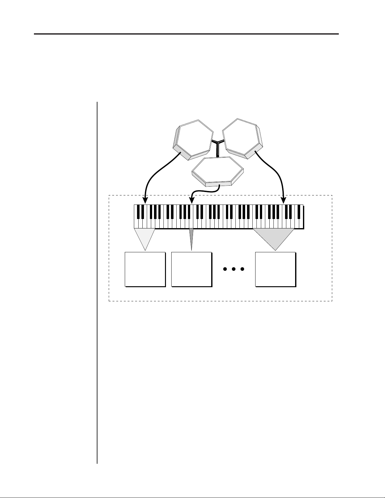
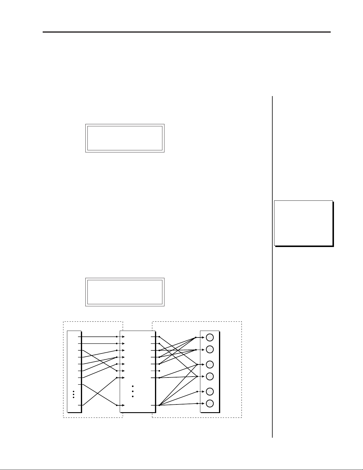
Procussion is organized as shown in the simplified diagram below.
Procussion operation manual
MIDI Drums
Zone 1
Zone 24
Zone 2
MIDI
Note # -
36
Zone
1
Drum
Stack
Up to 4 Instruments
which can be
controlled or switched
in various ways.
48
Drum
Stack
Up to 4 Instruments
which can be
controlled or switched
in various ways.
60 72 84 96
Zone
2
Up to 24 Zones
Zone
24
Drum
Stack
Up to 4 Instruments
which can be
controlled or switched
in various ways.
Zones larger than
1 note are used for
Tuned Percussion
PROCUSSION KIT
A number of sampled percussion instruments are mapped across a
keyboard or set of drum pads. Each instrument has many individual
attributes such as tuning, volume, pan, etc.
The Kit is a complete set of all program parameters for a set of up to 24
Procussion drum Stacks. There are 128 kit locations in the Procussion.
Kits 0-63 are unalterable factory kits; Kits 64-127 are user kits which can
be changed.
Stacks, which can be made of up to 4 percussion Instruments, are
assigned to MIDI key ranges called Zones. Up to 24 zones may be
assigned in one kit.
The instruments in a stack can be modulated in many ways or switched
on and off depending on various parameters such as velocity (how hard
a drum is played) or perhaps the position of the high hat pedal, sticking
speed, etc.
Page 7
Procussion operation manual
Connection Instructions - Basic Setup
CONNECTION INSTRUCTIONS
7
MIDI Controller
(MIDI Drum Pads, Keyboard, Sequencer, etc.)
MIDI Out
MIDI
IN OUT THRU
To
Main Outs
Male RCA plug
to
Male Phone plug
Aux. or
Tape In
OUTPUTS POWER
SUB 2
SUB 1
RR
LLLR
MAIN
OR
Amp
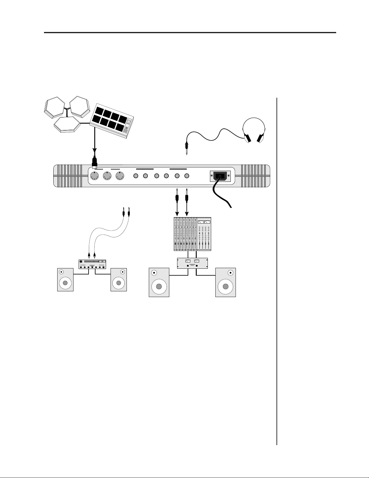
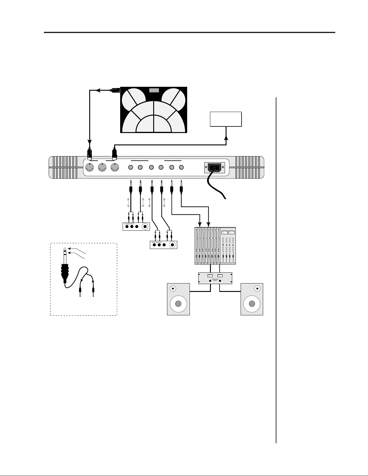
Setup #1 BASIC PAD SETUP
Use the Left Main Output
for Stereophones
STEREOMONO
Mixer
■
If Procussion does not
seem to be responding
correctly, make sure
that both Procussion
and your MIDI Controller are set to the same
MIDI channel.
Home Stereo
System
Speakers
Home Studio
System
This diagram shows a typical equipment setup for the Procussion.
MIDI In
- Procussion is controlled by MIDI messages received at the MIDI
In connector. Connect the MIDI In of the Procussion to the MIDI Out
connector of a MIDI controller such as a MIDI keyboard, MIDI Drum Pads
or MIDI sequencer.
Outputs
- Procussion is a high quality, stereo audio device. In order to
reproduce its wide dynamic range and frequency response, use a high
quality amplification and speaker system such as a keyboard amplifier or
home stereo system. A stereo setup is highly desirable because of the
added realism of stereophonic sound. Headphones can be used if an
amplifier and speaker system is not available. Plug stereo headphones
into the Left Main output jack. The Right Main output jack serves as a
mono output when the left jack is not plugged in.
Page 8

8
Quick Setup - MIDI Keyboard
Procussion operation manual
QUICK SETUP
Using the PROCUSSION with a MIDI Keyboard
These instructions will get you up and running in the shortest amount of
time. Connect Procussion to your sound system and MIDI keyboard as
shown on the following page and turn everything on.
SET LEVELS
1) Turn the Procussion's volume control to minimum.
2) Press the Master button on Procussion.
3) Turn the Data knob clockwise to the very last screen which reads,
“DEMO SEQUENCE”.
4) Press the Cursor button to move the flashing cursor to the bottom line
in the display.
5) Press Enter to start the demo sequence, then slowly turn up the volume
control to a comfortable listening level. You may have to adjust the
volume of your sound system. Press Enter again to stop the demo.
PROCUSSION SETUP
The Zone Map function re-maps every kit in Procussion to fit your MIDI
keyboard. This is much easier than having to modify each individual kit.
1) Press the Master button on Procussion.
2) Turn the Data knob to the screen which reads, “ZONE MAPS”.
3) Verify that the bottom line of the display reads “Kit”. If the display
reads something other than “Kit”, press the Cursor button to move the
flashing cursor to the bottom line in the display, then press it again so
that the flashing cursor line is underneath the word in the lower line.
Turn the data knob until it does read “Kit”.
4) Press the Master button to return to the main screen.
5) Play your MIDI keyboard. You should now be hearing sound. If not,
verify that the MIDI light on Procussion flashes as the keys are played.
If it doesn't flash, check the MIDI connection.
6) Turn the data knob clockwise to select another kit. Remember,
Procussion has 128 different kits! Have fun.
Page 9
Procussion operation manual
MIDI Controller
(MIDI Keyboard, Sequencer, etc.)
Connection Instructions - Keyboard Setup
9
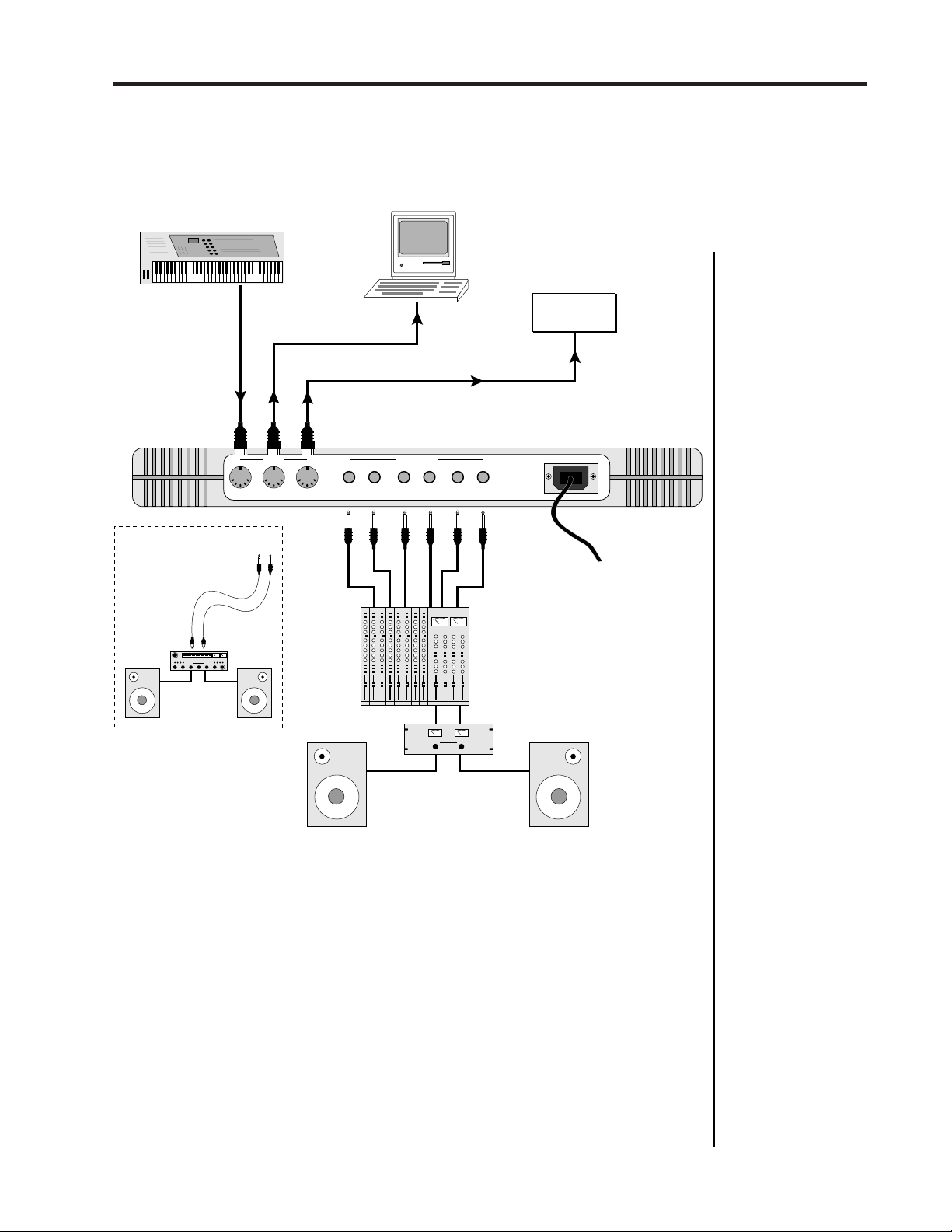
Setup #2 KEYBOARD SETUP
Computer
MIDI Out
MIDI In
Male RCA plug
to
Male Phone plug
Aux. or
Tape In
Home Stereo
System
MIDI
IN OUT THRU
To
Main Outs
OR
MIDI In
OUTPUTS POWER
SUB 2
SUB 1
RR
LLLR
Sub 2
MAIN
Sub 1
STEREOMONO
Main
Additional
MIDI
Devices
MIDI In
MIDI In
- Procussion is controlled by MIDI messages received at the MIDI
In connector. Any MIDI controller such as a MIDI keyboard, MIDI drum
pads or a computer can be connected.
MIDI Out
- The MIDI Out jack is normally used to transmit program data
to a computer or other device.
MIDI Thru
- MIDI Thru transmits an exact copy of the messages received
at the MIDI In jack to additional MIDI devices.
Outputs
- Procussion has three sets of programmable stereo outputs;
Main, Sub 1, and Sub 2. Specific sounds can be routed to one of these stereo
pairs in order to be further processed or mixed separately.
Page 10
10
Quick Setup - MIDI Drum Pads
QUICK SETUP
Using the PROCUSSION with Drum Pads
These instructions will get you up and running in the shortest amount of
time. Connect Procussion to your sound system and MIDI drum pads as
shown on the facing page (or on page 7) and turn everything on.
1) Play your MIDI drum pads and verify that the MIDI light on
Procussion flashes as the pads are played. If not, check the MIDI
connection.
2) Set Procussion to Kit 000, “Ampitheater” (or any of the kits marked
with an asterisk in the kit listing).
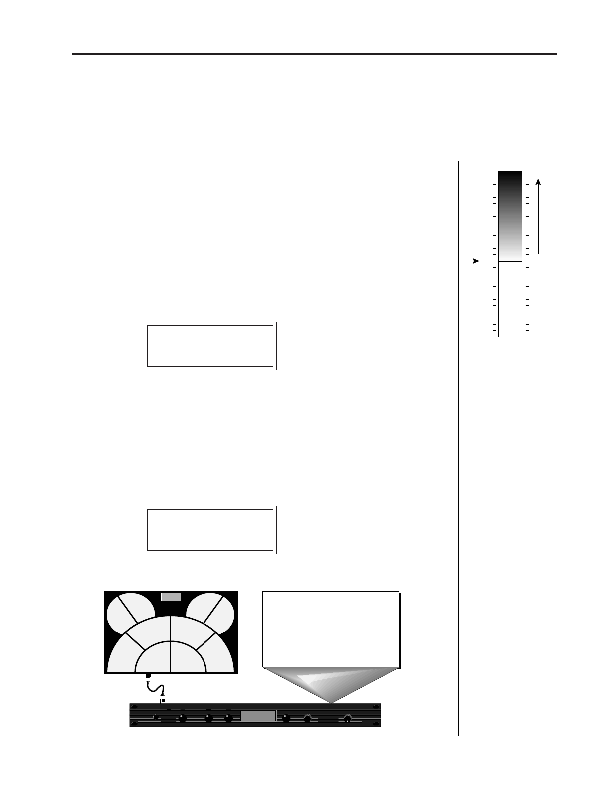
3) Assign each pad of your MIDI drum pad controller to a MIDI note
number using the Standard Factory Kit Layout on page 91. Set the
MIDI pads up however you like, but be sure to save your layout to the
pad controller when you have finished.
Procussion operation manual
4) Turn the data knob on Procussion clockwise to select another kit. Since
you used one of the Standard Kits as your model, most other
Procussion factory kits (marked *) will follow the same pad layout.
Your MIDI Controller
assigns each
Pad a MIDI Number
Note #43
Tom Tom
Note #38
Main Snare
drumKAT
Note #50
Note #45
Tom Tom
Note #39
Aux. Snare
Cymbal
Note #46
Perc.
Note #47
Tom Tom
95 96 98
MIDI Key #
Note #49
Cymbal
Note #52
Hi Hat
Aux. Snare
Cymbal
Percussion
Cymbal
Standard Factory Kit Layout
33 35 36 38 40 41 43 45 47 48 50 52 53
Note #51
Cymbal
55 57 59 60 62 64 65 67 69 71 72 74 76 77 79 81 838486 88 89 91 93
Main Snare
Tom Tom
Tom Tom
Tom Tom
Cymbal
Hi Hat
Use the Standard Factory Kit Layout to assign your Drum Pads so that most of the
Procussion Factory Kits will match up with your pad assignments.
Page 11
Procussion operation manual
Connection Instructions- Performance Setup
SETUP #3 LIVE PERFORMANCE SETUP
MIDI Controller
(MIDI Drum Pads, Keyboard, etc.)
11
MIDI In
MIDI Out
MIDI
IN OUT THRU
Sub Output
Return
(To Main Output)
drumKAT
OUTPUTS POWER
SUB 2
Effect Device
SUB 1
RR
LLLR
Send/Return
Send/Return
Effect Device
STEREOMONO
MAIN
Main Outputs
Additional
MIDI
Devices
MIDI In
Tip Ring
To Effect From Effect
SEND/RETURN CABLES
MIDI In
- Procussion is controlled by MIDI messages received at the MIDI
In connector. Connect the MIDI In of Procussion to the MIDI Out connector of a MIDI controller such as a MIDI percussion controller, or MIDI
keyboard.
MIDI Thru
- The MIDI Thru jack is used to connect additional MIDI
devices onto the MIDI chain. MIDI Thru transmits an exact copy of the
messages received at the MIDI In jack.
Outputs
- Each of the Sub 1 and Sub 2 output jacks on the Procussion are
stereo jacks. The tip of each jack (accessed when a standard phone plug is
inserted) connects to the left or right output of that group. If a stereo plug
is inserted, the Ring of the stereo plug serves as a signal Return which
sums into the Main outputs. See page 13 for additional details.
Page 12
12
Connection Instructions - Electronic Drum Kit
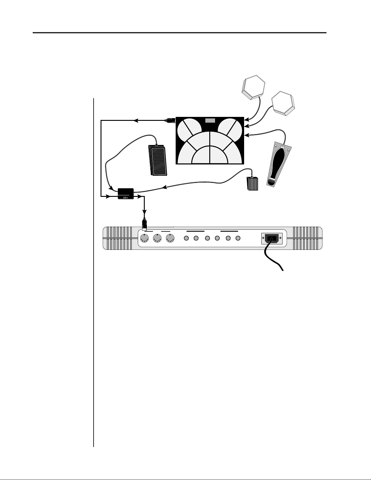
SETUP #4 FULL ELECTRONIC DRUMKIT
MIDI Controller
(MIDI Drum Pads or Trigger Device)
drumKAT
Trigger
Input 1
Control
Footswitch
■
Make sure that the
velocity response is
correctly calibrated on
your MIDI Drum Pads.
Pedal
Hi-Hat and
Control Pedal
Set to:
Modulation
PocKet
PEDAL
Pocket
Pedal
MIDI Out
Procussion operation manual
External Pads
dw
5
0
0
Kick Drum
0
Pedal
▼
When using the
Anatek Pocket Pedal,
the first pedal movement determines the
pedal's polarity.
Down 1st = Normal
Up 1st = Reversed
■
The Hi-Hat Pedal
corresponds to MIDI
key number 52 in the
Standard Factory Kit
Layouts.
MIDI In
MIDI
IN OUT THRU
SUB 2
OUTPUTS POWER
SUB 1
RR
LLLR
STEREOMONO
MAIN
The diagram above shows how to connect the Procussion as a full
electronic drum kit containing: a Kick Drum Pedal, Hi-Hat Pedal, MIDI
Drum Controller (with 2 external pads) and a Control Footswitch.
Kick Drum Pedal In
- In this example, a spring-loaded trigger pedal by
Drum Workshop is used. Connect the output of the pedal to Trigger #1
of your MIDI drum pads.
Hi-Hat Pedal In
- A standard electronic music voltage pedal functions as
a combination Hi-Hat/Control Pedal. In this example, an Anatek Pocket
Pedal is used to merge the pedal into the MIDI data. Connect the
Footswitch and CV Pedal to the inputs of the Pocket Pedal as shown in the
example above. See your dealer about obtaining a suitable control pedal.
MIDI
- Connect MIDI Out from your MIDI drum pads to MIDI In of the
Pocket Pedal. Connect MIDI Out of the Pocket Pedal to MIDI In of
Procussion.
Outputs
- Connect the audio outputs to your other equipment as shown
in setup procedures 1, 2, and 3.
Page 13
Procussion operation manual
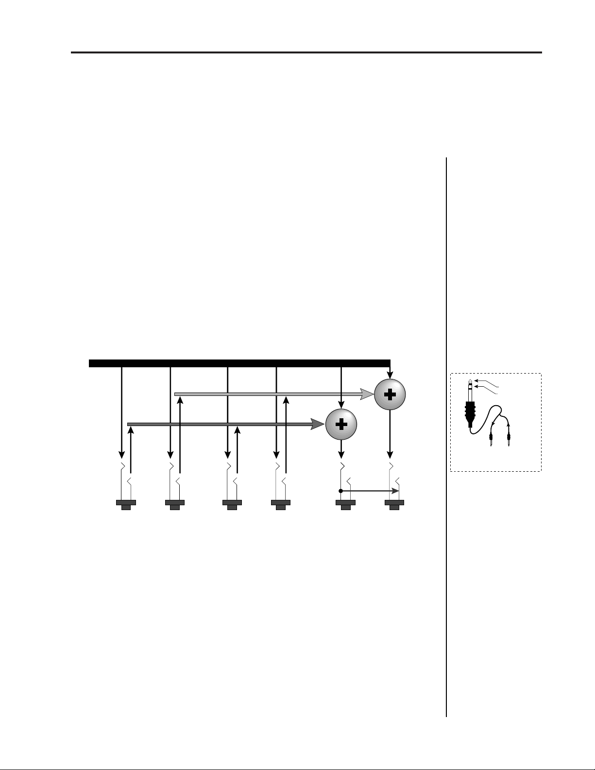
SUBMIX OUTPUTS
If a stereo plug is inserted into a Sub jack, the Ring of the stereo plug serves
as a signal Return which sums into the Main outputs.
Therefore, the Sub 1 and Sub 2 jacks can serve as effect sends and returns
in order to further process selected instruments and then return them to
the main mix.
The diagram below shows the Sub 1 and Sub 2 jacks being used as send/
returns in order to further process selected Procussion instruments
without using the effects bus on the mixing board. In a pinch, the effect
returns could also be used to sum additional instruments into the main
outputs of the Procussion.
Submix I/O
13
Procussion Output Section
L Bus
R Bus
Tip
RL RL RL
The Sub 1 and Sub 2 jacks can be used as effect returns to the Main Outputs.
Tip
Ring
SUB 2 SUB 1 MAIN
Ring
Tip
Ring
Tip
Tip Tip
Ring
Ring
POWER UP!
The power switch is located on the left side of the front panel. The
Procussion and its MIDI controller may be turned on in any order. When
power is applied, the liquid crystal display will light, indicating that the
Procussion is operating.
Sub Output
Return
(To Main Output)
Tip Ring
To Effect From Effect
SEND/RETURN CABLES
■
Use Send/Return
cables as shown above
to access the Submix
Return points.
You may have noticed that there is no 110/220 Volt power selector
switch on the Procussion
.
Procussion automatically switches itself for 110 or 220 Volt operation.
Page 14

14
Procussion operation manual
Page 15

Procussion operation manual Basic Operation
BASIC OPERATION
15
Page 16

16
Procussion operation manual
Page 17
Procussion operation manual Main Controls
BASIC OPERATION
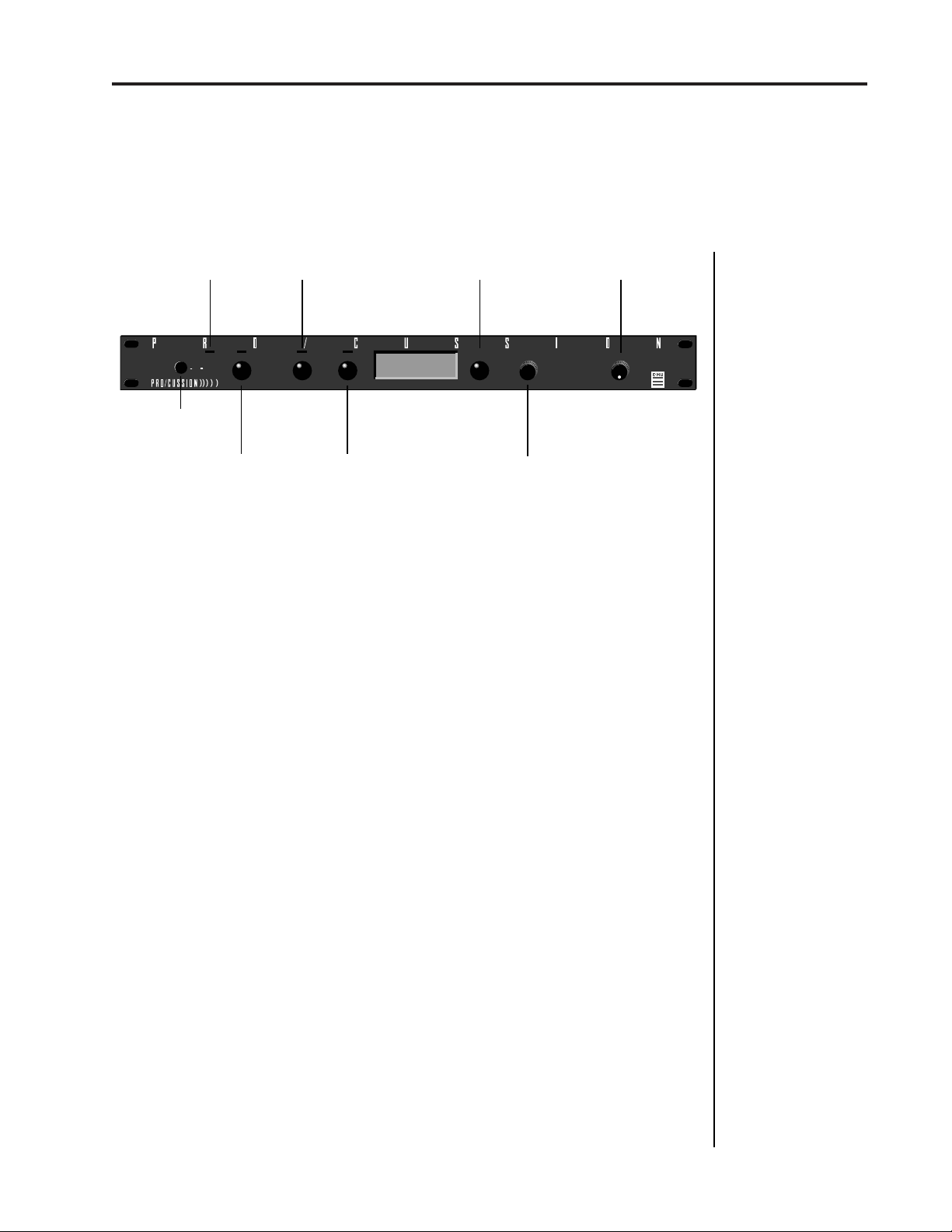
MAIN CONTROLS
17
MIDI
ACTIVITY
I/O
MAXIMUM PERCUSSION MODULE
POWER
SWITCH
MASTER MENU
SELECT
■
Power Switch
■
MIDI Activity LED
■
Master Menu Select Button
EDIT MENU
SELECT
MASTER EDIT DATA VOLUME
BUTTON
- Switches AC power to the Procussion ON and OFF.
- Indicates that MIDI data is being received.
C01 Vol127 Pan=K
031 Sluggo Drums
DISPLAY
ENTER
- The Master menu contains parameters
CURSOR
CONTROL
CURSORENTER
DATA ENTRY
CONTROL
VOLUME
CONTROL
that affect the entire machine, not just certain Kits. An illuminated LED
above the button indicates that you are in the Master menu.
■
Edit Menu Select Button
- The Edit menu is used when you want to
change parameters of a Kit. An illuminated LED above the button
indicates that you are in the Edit menu.
■
Enter Button
- The Enter button is used as a “Home” key or to initiate
a particular operation within the Procussion. The red LED above the enter
button flashes to indicate that the Procussion is waiting for your response.
■
Cursor Control
- This button moves the cursor to the next parameter
on the display. (The cursor is a little flashing line underneath one of the
parameters in the display.) Press the cursor control repeatedly until the
cursor is underneath the desired parameter. The cursor can also be moved
bidirectionally using the data entry control while the cursor select button
is being held down (i.e. Press and hold the cursor button and turn the data
entry knob).
■
Data Entry Control
- The data entry control is a stepped, variable control
which is used to change parameter values. The control increments or
decrements the current value one unit with each click.
■
Volume Control
- This is the master volume control for all audio
outputs. Note: For maximum dynamic range, set this control at full level.
Page 18
18
BASIC OPERATION
KIT SELECTION
Press the cursor key repeatedly until the cursor is underneath the kit
number. (The cursor is a little flashing line underneath one of the
parameters in the display.) As the data entry control is rotated, the kit
number and name will change. The displayed kit will be assigned to the
displayed MIDI channel. Kit numbers range from 000 to 127.
Procussion operation manualChannel Selection
■
If your Procussion is
not responding properly
or plays the wrong kit,
make sure that
Procussion and your
MIDI controller are set
to the same MIDI channel and that the MIDI
Volume is turned up.
For more information
about MIDI, see MIDI
Realtime Controls on
page 44.
C01 Vol127 Pan=K
00
0 Kit Name ÷ Kit Information
÷ MIDI Channel Parameters
MIDI CHANNEL SELECTION
Press the cursor key repeatedly until the cursor is underneath the channel
number. (The cursor is a little flashing line underneath one of the
parameters in the display.) Rotate the data entry control to select MIDI
channel 01-16. As the channel is changed, the display will change to show
the kit, volume and pan associated with the displayed channel.
C0
1 Vol127 Pan+0
000 Kit Name
CHANNEL VOLUME
Press the cursor key repeatedly until the cursor is underneath the volume
value. Rotate the data entry control to select volume 00-127. (This is the
same parameter as MIDI volume control #7, and changes made over
MIDI will be shown in the display.)
■
Channel Pan should
normally be set to “K”
unless realtime control
of panning is desired.
This will allow the
preprogrammed pan
settings for each zone
or stack to be used.
CHANNEL PAN
Press the cursor key repeatedly until the cursor is underneath the pan
value. Rotate the data entry control to select pan values -7 to +7 or “K”.
When “K” is selected, the pan value specified in the kit is selected. Any
other value will override the pan parameter in the kit. (This is the same
parameter as MIDI pan control #10, and changes made over MIDI will be
shown in the display.)
Page 19
Procussion operation manual Multi-Timbral Operation
BASIC OPERATION
MULTI-TIMBRAL OPERATION
Multi-timbral operation means that the Procussion can play more than
one kit at the same time. For example, a MIDI sequencer could be playing
one kit while you play along on another. To access multiple kits on
different MIDI channels simultaneously, follow these instructions:
1. Set the MIDI mode to MULTI-Mode, using the MIDI mode function in
the Master menu (page 24).
2. Decide which MIDI channels you wish the Procussion to receive, and
turn all other channels OFF using the MIDI Enable function in the Master
menu (page 26). Up to 16 channels can be selected simultaneously!
19
3. Select the desired kit for each of the MIDI channels you wish the
Procussion to receive using the MIDI Channel/Kit selection screen (see
previous instructions).
4. Procussion will now respond multi-timbrally on the MIDI channels
you have specified. The volume and pan position parameters can be
adjusted over MIDI (for each MIDI channel) or using the Cursor and Data
Entry control in the MIDI Channel/Kit selection screen.
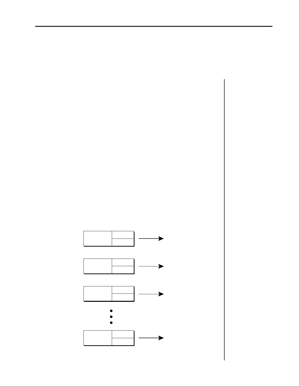
Channel 01
Channel 02
Channel 03
Volume
Pan
Volume
Pan
Volume
Pan
KIT
KIT
KIT
■
Kit numbers for each
MIDI channel can also
be selected via MIDI
program changes.
(This is so simple that it
is often overlooked.)
Channel 16
Each of the 16 MIDI channels can be assigned to play a specific kit in Procussion.
Volume
Pan
KIT
Page 20
20
Master Menu
MASTER MENU
The Master menu contains functions that affect the overall operation of
the Procussion. For example, changing the Master Tune will change the
tuning of all the drum kits, not just the one currently displayed.
TO ENABLE THE MASTER MENU
Press the Master key, lighting the LED. The current screen will be the one
most recently selected since powering up the Procussion. The cursor will
appear underneath the first character of the screen heading on line one.
TO SELECT A NEW SCREEN
Press the cursor key repeatedly (or hold the cursor key while turning the
data entry control) until the cursor is underneath the screen title heading.
(You may also press the Enter button to return the cursor to “Home”
position.) Rotate the data entry control to select another screen.
Procussion operation manual
TO MODIFY A PARAMETER
Press the cursor key repeatedly (or hold the cursor key while turning the
data entry control) until the cursor is underneath the parameter value.
Rotate the data entry control to change the value.
TO RETURN TO KIT SELECT MODE
Press the Master key, turning off the LED.
MASTER MENU FUNCTIONS
MASTER TUNE
Master Tune adjusts the overall tuning of all kits so that the Procussion
may be tuned to other instruments. The master tuning range is ± 1
semitone in 1/64th semitone increments. A master tune setting of "00"
would indicate that the Procussion is perfectly tuned to concert pitch
(A=440 Hz).
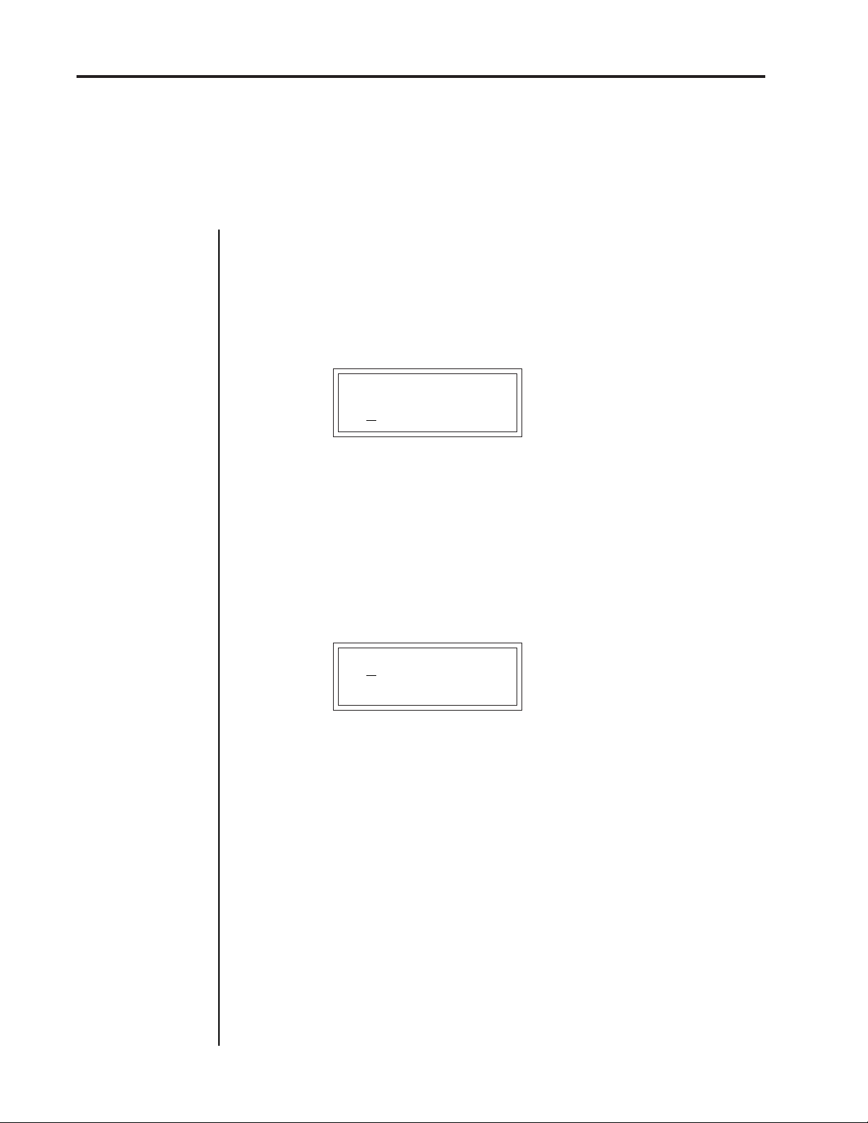
MASTER TUNE
+63
Page 21
Procussion operation manual
TRANSPOSE
This function transposes the key of the Procussion in half-step intervals.
The transpose range is ± 12 semitones or one octave.
TRANSPOSE
+12 semitones
SUBMIX OUTPUTS
The function provides a convenient method of assigning types of instruments a particular output. For example, you might want to direct the kick
drum to one of the submix output for external processing. Each zone may
be assigned to a particular submix group for each kit (As programmed in
the Edit menu). The Submix Output function assigns each of the 16
Submixes to a particular output channel or turns the submix Off. The
Submix Output function selects at which output jack each submix group
will appear. The choices are: Main, Sub 1, Sub 1L, Sub 1R, Sub 2, Sub 2L,
Sub 2R, or Layer. When Layer is selected, each layer in the stack will be
directed to a separate output jack. This function also allows you to change
the output assignment of the factory kits.
SUBMIX OUTPUTS
Kick ->Main
Transpose
21
MASTER MENU
SUBMIX LAYER
Layer 1---- > Sub 1L
Layer 2---- > Sub 1R
Layer 3---- > Sub 2L
Layer 4---- > Sub 2R
■
If no plugs are inserted
into the sub outputs, the
audio will be automatically directed to the main
outputs.
EDIT MENU MASTER MENU
Layer 4
Outputs
L
Main
R
L
Sub 1
R
L
Sub 2
R
Zone
1
2
3
4
5
6
7
8
24
(Sub 16 Set to Submix Layer)
Each zone is assigned to a submix group in the Edit menu. Each submix group is assigned to
the output jacks in the Master menu. The Edit menu functions are programmed for each kit.
The Master menu functions affect ALL kits.
Submix
Kick
Snare
Hi-hat
Tom 1
Tom 2
Sub 6
Sub 7
Sub 16
Layer 1
Layer 2
Layer 3
Page 22

22
MIDI Mode
MASTER MENU
Procussion operation manual
MIDI MODE
This function selects one of the four MIDI modes and the MIDI system
exclusive ID number.
■ Omni mode - Procussion responds to note information on all MIDI
channels and plays the kit currently displayed in the main screen.
■ Poly mode - Procussion only responds to note information received on
the currently selected MIDI channel (on the kit selection screen) and plays
that channel’s associated kit.
■ Multi mode - Procussion responds to data on any combination of MIDI
channels and plays the specific kit associated with each of the MIDI
channels.
■ ID number - This function allows an external programming unit to
distinguish between multiple Procussion units. When an external programmer is being used, each Procussion should have a different ID
number. When transferring SysEx data from one Procussion to another,
both units must have the same ID number.
MIDI MODE ID
Omni 00
GLOBAL VELOCITY CURVE
Incoming velocity data can be modified by a velocity curve in order to
provide different types of dynamics in response to your playing or to
better adapt to a MIDI controller. This function allows you to select one
of the 9 velocity curves or leave the velocity data unaltered (Linear) for
each MIDI channel. When "Kit" is selected, the velocity curves selected in
the kits are used. For more information on the velocity curves, see page
43.
GLOBAL VEL CURVE
C01 Curve #4
Page 23
Procussion operation manual Global Pitch Bend
260
60
120
180
0
127
0
Output
Amount
More
Tempo
Played
Trigger
Tempo
MASTER MENU
GLOBAL TRIGGER TEMPO
Trigger Tempo is a function which generates a control signal based on the
tempo of your playing. When your playing tempo exceeds the selected
Trigger Tempo, the amount of the control signal begins to increase from
zero. This control signal can be used either to switch between drums in a
stack or as a general controller which can affect virtually any parameter
(set in the Edit menu). For example, Trigger Tempo could be routed to
brighten the Tone as you play faster. The Global Trigger Tempo can be set
to any tempo from 20 BPM (Beats-Per-Minute) to 260 BPM or set to use
incoming MIDI clocks as the reference. Alternately, the Trigger Tempo set
in each kit may be used (turn data knob all the way counter-clockwise).
23
GLOBAL TR TEMPO
101 BPM
ZONE MAPS
This function automatically sets up Procussion to respond to various
types of MIDI pad controllers without reprogramming the controller.
Select the Zone Map for the type of controller you are using. There are
preset Zone Maps to match many popular controllers as well as two user
definable maps. If you are using a MIDI keyboard, use the Kit Zone
Map. Zone Maps can be selected for each of the 16 MIDI channels.
ZONE MAPS
C01 Drum Kat
Zone Maps assign
MIDI Numbers to Zones
Note #43 -----> Zone 3 = Snare Stack 1
Note #46 -----> Zone 4 = Ambient Snare Stack
Note #48 -----> Zone 11 = Tiny Tom Stack
Note #50 -----> Zone 12 = Med. Tom Stack
Note #53 -----> Zone 13 = Big Tom Stack
Note #55 -----> Zone 14 = Huge Tom Stack
Note #58 -----> Zone 7 = Hi-Hat Stack
Note #60 -----> Zone 17 = Splash Stack
Note #62 -----> Zone 16 = Crash Stack
Note #65 -----> Zone 15 = Ride Stack
CURSORENTER
E-mu Systems, Inc.
Your MIDI Controller assigns each
Pad a MIDI Number
Note
#58
Note
#48
Note
#60
drumKAT
Note
#50
Note
#43
Note
#53
Note
#46
Note
#62
Note
#65
Note
#55
MIDI
POWER
ON/OFF
C01 Vol127 Pan=K
000 Kit Name
MAXIMUM
PERCUSSION MODULE
CUSSION
PRO
MASTER EDIT DATA VOLUME
This diagram shows how MIDI key numbers are “mapped” to Procussion Zones.
■
When the tempo of
your playing exceeds
the selected Trigger
Tempo, the amount of
the control signal
increases from zero.
▼
Make sure you are
setting the Zone Map
for the correct MIDI
channel.
■
When using a
preprogrammed Zone
Map, set your MIDI
controller to the
following Kit numbers:
Alesis - default
drumKat - Kit 21
E-mu SP-12 - default
Impulse - default
Roland Octa I - Kit A
Roland Octa II - Kit 11
Roland Pad80 - Kit 11
Roland SPD8 - Kit 1
Roland R5 - default
Roland R8 - default
Page 24
24
User Zone Maps 1 + 2
USER ZONE MAP 1 + 2
This function allows you to program the two user definable Zone Maps.
The User Zone Maps are useful to route MIDI note data from existing
drum machine patterns to the appropriate stacks in Procussion for drum
replacement. Each zone may be assigned a MIDI key range. The User
Zone Maps are retained in memory when power is removed.
Procussion operation manual
USER ZONE MAP 1
Z01 036 -> 037
DRUM REPLACEMENT WITH THE USER ZONE MAPS
The two User Zone Maps can be used to replace tracks from your drum
machine or MIDI sequencer with killer Procussion Stacks.
1) Press the Master button on Procussion.
2) Turn the data knob until you find the screen:
ZONE MAPS
C01 Kit
3) Press the cursor button twice so that the flashing cursor line is
underneath the word “Kit”. (There may be another word there, but
place it underneath the word in the second line, OK?)
4) Turn the data knob until the display reads:
ZONE MAPS
C01
User 1
5) Press the Enter button and turn the data knob until the display reads:
USER ZONE MAP 1
Z01 036->036
Page 25
Procussion operation manual
6) Press the cursor button to move the flashing cursor line to the second
line of the display under Z01. Turning the data knob will show you the
key numbers which are currently mapped to each zone.
7) Assign each of your drum machine buttons to a zone. Place the cursor
underneath the key number and press the button on you drum machine to automatically assign the correct number. The chart at the
bottom of this page shows which types of Procussion drum sounds will
be assigned to each zone. For example, if you want the first button on
your drum machine to function as a snare drum, and it is assigned to
note number 43, set up the display to look like this:
User Zone Maps
25
USER ZONE MAP 1
Z03 04
3->043
Zones 3-6 are
reserved for Snare
Drums (see below).
8) Continue assigning zones until each button on your drum machine is
assigned to a different zone, then press the Master button to exit the
module.
9) Start the drum machine and verify that the correct types of drums are
being played. If the sounds are not assigned as you want them, go back
into the “User Zone Map” screen and re-assign them.
The chart below shows how the various types of drums are mapped to the
User Zone Maps in the Procussion factory presets.
PROCUSSION FACTORY ZONE ASSIGNMENTS
Zone 1........... Kick Drum
Zone 2........... Kick Drum
Zone 3........... Snare Drum
Zone 4........... Snare Drum
Zone 5........... Snare Drum
Zone 6........... Snare Drum
Zone 7........... Hi-Hat
Zone 8........... Hi-Hat
Zone 9........... Hi-Hat
Zone 10......... Hi-Hat
Zone 11......... Tom
Zone 12......... Tom
Zone 13......... Tom
Zone 14......... Tom
Zone 15......... Cymbal
Zone 16......... Cymbal
Zone 17......... Cymbal
Zone 18......... Cymbal
Zone 19......... Misc. Percussion
Zone 20......... Misc. Percussion
Zone 21......... Misc. Percussion
Zone 22......... Misc. Percussion
Zone 23......... Misc. Percussion
Zone 24......... Misc. Percussion
■
All Procussion kits
will not fit into the factory zone assignment
scheme so this chart
should be used as a
basic guide rather
than an absolute rule.
Page 26
26
MASTER MENU
Procussion operation manualUser Zone Maps
ENVELOPE MODE
This function allows you to select either a Trigger or Gate mode for each
of the 16 MIDI channels when MIDI note on messages are received. For
more information on the Envelope Generators, see page 36.
■ Trigger mode allows a sound's volume envelope to cycle through all
its stages when a note on is received. Trigger mode is almost always used
with MIDI drum pads and even when using a MIDI keyboard.
■ Gate mode allows a sound's volume envelope to cycle through its Attack
and Hold stages when a MIDI note on command is received. When the
MIDI note off command is received, the Decay phase begins immediately.
Gate mode is used when you want the length of the sound to be controlled
by how long a key is held.
ENVELOPE MODE
C01 Trigger
MIDI ENABLE
When in MIDI Multi mode, this function lets you turn each MIDI channel
On or Off. This is useful when you have other MIDI devices connected
and do not want the Procussion to respond to the MIDI channels reserved
for the other devices. MIDI Enable only operates when in Multi Mode.
MIDI ENABLE
C01 On
PROGRAM CHANGE
This function lets the Procussion utilize or ignore incoming MIDI program (also called Preset or Kit) change commands for each channel.
PROGRAM CHANGE
C01 On
Page 27
Procussion operation manual
MIDI Program Change
MIDI MODE CHANGE
This function selects whether or not MIDI mode change commands
(omni, poly, etc.) are accepted or ignored when received over MIDI (see
MIDI Mode).
MIDI MODE CHANGE
Disabled
MIDI CONTROLLER ASSIGN
The Procussion allows you to assign up to six realtime control sources
from your MIDI controller. These control sources could be foot pedals,
data sliders or whatever. In this screen, you set up which controllers will
be received by Procussion. What effect the controller will have is programmed separately for each Kit. Volume and Pan each have their own
controller. Four other MIDI controllers are assigned a letter A-D. Each of
the controllers can be assigned to a MIDI realtime controller number from
01-31. The MIDI controller number will be automatically sensed by
simply moving the controller (pedal, wheel, etc.) when the cursor is
underneath the value. This way you don't have to remember the controller numbers. For more information, see MIDI Realtime Controls in the
Programming Basics section.
CONTROLLER#
VOL:07 PAN:10
Next Screen:
CONTROLLER# ABCD
01 02 03 04
27
MASTER MENU
Some of the standard
MIDI Controller numbers are listed below.
1 - Modulation Wheel or
Lever
2 - Breath Controller
3 - Pressure: Rev 1 DX7
4 - Foot Pedal
5 - Portamento Time
6 - Data Entry
7 - Volume
8 - Balance
9 - Undefined
10 - Pan
Page 28
28
MIDI Footswitch Assign
MASTER MENU
■
Note that Procussion
does not have footswitch
inputs on the rear panel.
Use the footswitch inputs
on your MIDI controller
and set Procussion to
receive the footswitch
commands over MIDI.
Some of the standard
MIDI switch numbers
are listed below.
64 - Sustain Switch
(on/off)
65 - Portamento Switch
(on/off)
66 - Sostenuto (chord
hold, on/off)
67 - Soft Pedal (on/off)
69 - Hold Pedal 2 (on/off)
Procussion operation manual
MIDI FOOTSWITCH ASSIGN
Like the MIDI Controllers, 4 MIDI footswitches can be assigned to MIDI
footswitch numbers. Footswitches may be assigned numbers from 64-79.
The MIDI footswitch number can be automatically sensed by simply
pressing the footswitch when the cursor is underneath the value. Destinations for the footswitch controllers are programmed in the Edit menu.
FOOTSWITCH# 1234
64 65 66 67
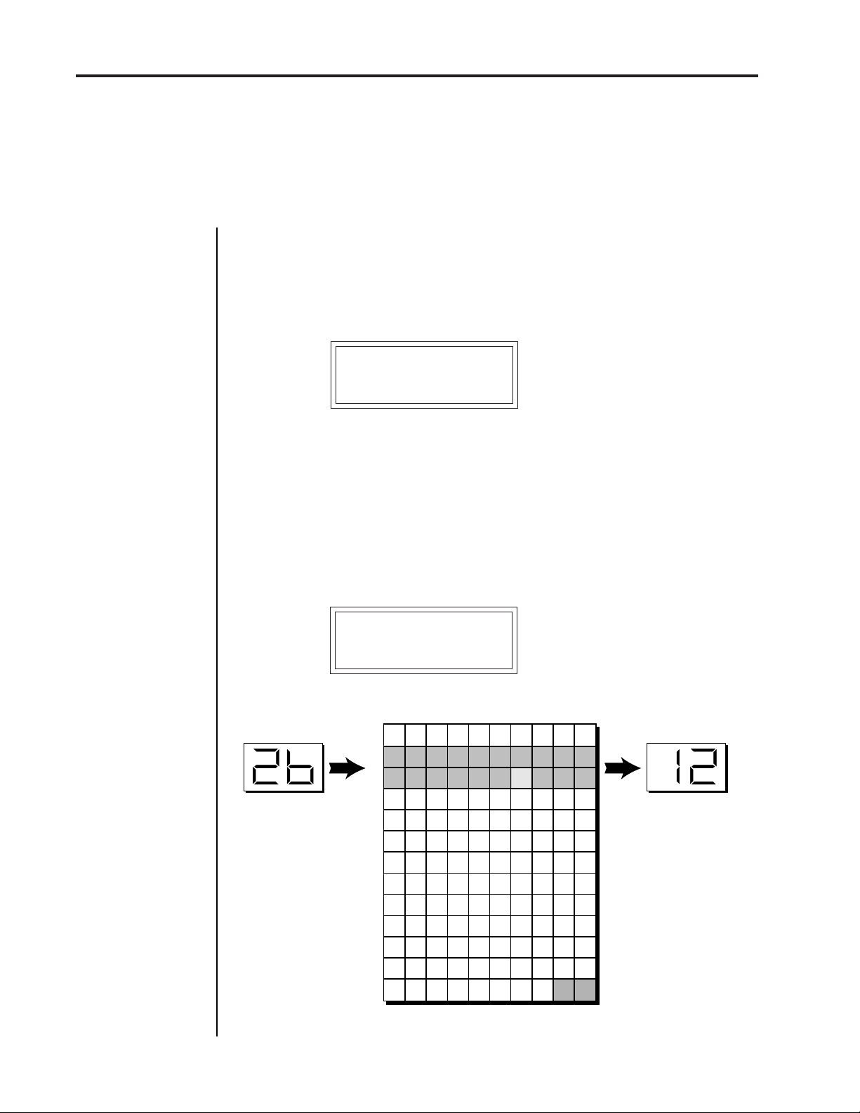
MIDI PROGRAM ➔KIT
Incoming MIDI program changes can be “mapped” to call a different
numbered kit. This is a handy feature when you want a specific program
number sent from your controller to be linked with a specific kit on the
Procussion. Simply selecting a program on your MIDI controller will
automatically call up the proper Procussion kit. Any of the kits in the
Procussion may be mapped to any incoming MIDI program change
number.
MIDI PROG > KIT
Selected
Program
026 > 012
0 1 2 3 4 5 6 7 8 9
0
00 01 02 03 04 05 06 07 08 09
44 191 50 01 15 88 151 78 99 88
1
34 73 106 55 43 75 120 121 108
2
30 31 32 33 34 35 36 37 38 39
3
40 41 42 43 44 45 46 47 48 49
4
50 51 52 53 54 55 56 57 58 59
5
60 61 62 63 64 65 66 67 68 69
6
70 71 72 73 74 75 76 77 78 79
7
80 81 82 83 84 85 86 87 88 89
8
90 91 92 93 94 95 96 97 98 99
9
100 101 102 103 104 105 106 107 108 109
10
110 111 112 113 114 115 116 117 118 119
11
12
120 121 122 123 124 125 126 127
-- Selecting Kit 26 calls up Kit 12
12
Mapped
Program
This chart shows how MIDI program changes can be re-mapped. In this example, program
changes 10-29 have been re-mapped. All other programs will be selected normally.
Page 29
Procussion operation manual
AUTO SELECT
When editing a zone or stack parameter, the current zone or stack can be
"auto-selected" by simply playing it. While this is a very handy feature, it
can sometimes be confusing. Therefore, Auto-Select can be turned On or
Off.
AUTO-SELECT
On
REMOTE EDIT
The Remote Edit function allows access to the front panel controls using
MIDI note-on events. When Remote Edit is turned On, MIDI key numbers
0-5 activate the following functions.
Auto-Select
29
MASTER MENU
MIDI NOTE # FUNCTION
0 Play Current Zone
1 Toggle MASTER menu
2 Toggle EDIT menu
3 Cursor
4 Increment Value
5 Decrement Value
Remote Edit is designed to be used with MIDI drum pads. Create a preset
on your MIDI drum pads which assigns the pads to MIDI key numbers
0-5. Now you can program Procussion without putting down your sticks.
Example - To change the stack assigned to a zone using Remote Edit:
a) Hit pad 2 (Edit) to enter the edit menu.
b) Hit pad 4 twice (Increment) to move to the stack select screen.
c) Hit pad 3 twice (Cursor) to move the cursor down to the lower line.
d) Hit pad 4 (Increment) to increment the stack number.
e) Hit pad 0 (Play Current Zone) to hear the new stack.
f) Alternate between steps "d" and "e" until you have the desired stack.
REMOTE EDIT
Off
Page 30
30
■
To Record MIDI
Data into a
Sequencer:
1. Setup your
sequencer to
receive system
exclusive data.
2. Place sequencer
into record mode,
then Send Data.
Procussion operation manualSend MIDI Data
SEND MIDI DATA
This function will send MIDI System Exclusive data to the MIDI Out port
of Procussion. The MIDI data can either be sent to a computer/sequencer
or to another Procussion. Using the cursor key and the data entry control,
select the type of MIDI data you wish to transmit. The choices are:
Master Settings: Transmits all parameters in the Master menu except
program/kit map and viewing angle. This includes the Kit, Volume, and
Pan information for all 16 MIDI channels.
Program/ Kit Map: Transmits only the program/kit map.
■
To Receive MIDI
Data from a
Sequencer:
1. Simply play back
the sequence into
Procussion.
▼
When transferring
SysEx data from one
Procussion to
another, the ID
numbers of both
units must match.
User Zone Maps: Transmits user zone maps 1 and 2.
Factory Kits: Transmits all the factory kits.
User Kits: Transmits all the user kits.
Any Individual Kit: Transmits only the selected kit.
The Enter LED will be flashing. Press the Enter button to confirm the
operation. To receive MIDI data, simply send the MIDI data into
Procussion from another Procussion or your sequencer.
SEND MIDI DATA
024 Industry
VIEWING ANGLE
This function allows you to change the viewing angle of the display so
that it may be easily read from either above or below. The angle is
adjustable from +7 to -8. Positive values will make the display easier to
read when viewed from above. Negative values make the display easier
to read from below.
VIEWING ANGLE
+7
Page 31

Procussion operation manual
DEMO SEQUENCE
Procussion contains a play-only sequencer in order to give you some idea
of what is possible using this amazing machine. Press the cursor switch
to move the cursor to the bottom line of the display. The Enter LED will
begin flashing. Press the Enter switch to start the sequence. The Enter LED
will be lit and the bottom line of the display will change to "Stop". Pressing
the Enter button again will stop the sequence.
DEMO SEQUENCE
Start Sequence
Demo Sequence
31
Page 32

32
About Procussion
Procussion operation manual
about
PROCUSSION
Procussion utilizes digital recordings of real percussion instruments for
the basis of its sound. This is similar to a tape recorder except that in the
Procussion, the sounds are permanently recorded on digital memory
chips.
To perform this modern miracle, sounds and instrument waveforms are
first sampled into the Emulator III, our top of the line, 16 bit stereo digital
sampler. After the sounds and waveforms have been truncated, looped
and processed, they are “masked” into the Procussion ROM (Read Only
Memory) chips.
Conceptually, the sampling process is very simple, as shown in the Basic
Sampling System diagram. As a sound wave strikes the diaphragm of a
microphone, a corresponding voltage is generated. To sample the sound,
the voltage level is repeatedly measured at a very high rate and the
voltage measurements are stored in memory. To play the sound back, the
numbers are read back out of memory, converted back into voltages, then
amplified and fed to a speaker which converts the voltage back into sound
waves. Of course, playing back 32 channels at different pitches tends to
complicate matters, but this is basically how it works. In Procussion, we
have left out the Analog/Digital converter stage since the sounds are
already sampled for you.
Analog/Digital
Converter
1011001
1011001
Basic Sampling System
Memory
10100101001
01010010100
10101010100
10101001010
3V
0V
-3V
Digital/Analog
Converter
1011001
-1V -2V3V-1V-2V3V1V
Amplifier
Page 33

Procussion operation manual
Instrument
TonePitch
INSTRUMENT LAYER
DelayReverse
Sample
Start
DCA
Pan
Instrument Layer Block Diagram
PROGRAMMING BASICS
R
L
41
Level
Accent
Modulation Destinations
Volume
Envelope
Hld
Atk Dcy
INSTRUMENT LAYER BLOCK DIAGRAM
The diagram above shows the basic architecture of a single instrument
layer. The large, horizontal lines and arrows show the audio signal path.
The small vertical arrows indicate parameters which can be modulated.
The Instrument is one of the 221 sampled percussion sounds stored in
ROM. The instrument can be reversed or delayed and the pitch, tone and
sample start point can be modulated as shown by the small arrows.
Following the signal path, the sound passes through a DCA (Digitally
Controlled Amplifier) which controls the volume of the instrument. In
addition to Volume and Accent modulation, a Volume Envelope Gen-
erator can control the DCA in order to shape the volume of the instrument
over the course of the note.
Lastly, the sound reaches the Panning Network, which positions the
instrument in the stereo field.
CENTER of ZONE
-127 +1280
+-
KEY NUMBER
Key Number is a value generated at the start of the note which varies
according to which key is played. The center of the zone acts as a zero
reference (no effect at the center) and increases in the positive and
negative direction as shown above. The end keys of the zone are always
the maximum values (-127, +128), but these can be scaled in the patch.
Page 34

42
Stack Block Diagram
PROGRAMMING BASICS
Procussion operation manual
Modulation Sources:
Velocity
Key Number
Trigger Tempo (Rate)
Random
MIDI Control A/B/C/D
Pressure
Pitch Wheel
LFO
Destinations:
Pitch, Pitch 1/2/3/4
Volume, Volume 1/2/3/4
Accent, Accent 1/2/3/4
Attack, Attack 1/2/3/4
Hold, Hold 1/2/3/4
Decay, Decay 1/2/3/4
Pitch Env. Amount
Pitch Env. Amt 1/2/3/4
Pitch Env. Decay
Pitch Env. Dcy 1/2/3/4
Pan, Pan 1/2/3/4
Tone, Tone 1/2/3/4
Sample Start
Sample Start 1/2/3/4
LFO Rate, LFO Amount
VELOCITY
STACK
INSTRUMENT LAYER 1
INSTRUMENT LAYER 2
INSTRUMENT LAYER 3
INSTRUMENT LAYER 4
Instrument
Wet Snare 2
DelayReverse
Sample
Start
TonePitch
KEY
NUMBER
TRIGGER
RATE
RANDOM
Modulation Sources
DCA
Accent
CONTROL
Level
MIDI
A/B/C/D
Volume
Envelope
Hld
Atk Dcy
PRESSURE
Pan
PITCH
WHEEL
R
L
LFO
Rate Amt
■
Drum Kits may be
assembled using the
factory stacks or by
creating your own custom stacks. There are 8
custom stacks for each
kit in Procussion.
STACK BLOCK DIAGRAM
The diagram above shows the organization of a Procussion Stack. You
can think of a stack as a single sound, although it can be made up of up
to four different instruments. "Stacking" instruments, in combination
with the various modulation parameters can create almost unlimited
variations in the final sound.
At the stack level, a modulation source can control up to four destinations
or one destination can be controlled by up to four sources. The modulation sources can be applied to an individual instrument layer or all four
layers simultaneously. The possible modulation routings are completely
flexible as shown in the example above.
Three of the modulation destinations, Tone, Sample Start, and Pan cannot
be dynamically varied during the course of the note. Their value is
"locked in" at the start of the sound. All the other destinations marked
with black arrows can be dynamically varied over time.
Page 35

Procussion operation manual
PROGRAMMING BASICS
VELOCITY CURVES
Incoming velocity values can be scaled by one of the 10 velocity curves in
order to match your playing style or better adapt to the MIDI controller.
Selecting "Linear" leaves the velocity data unaltered and "Constant"
always outputs the maximum value of 127. The velocity curve can be
selected globally (for all kits) for each MIDI channel (Master menu), or be
programmed separately for each individual kit. Experiment with the
curves to find the one that works best for your style and MIDI controller.
Velocity Curves
43
Compresses Velocity
Range. For Hard
Hitters.
Expands Velocity
Range. Soft -> Loud.
Outputs High Values.
Linear Dynamics.
Outputs High Values
Only.
Limits Dynamics.
CURVE 1
127
Output
0
0 127
Input
CURVE 3
127
Output
0
0 127
Input
CURVE 5
127
Output
0
0 127
Input
CURVE 7
127
Output
0
0 127
Input
LINEAR
127
CURVE 2
127
Output
0
0 127
Input
CURVE 4
127
Output
0
0 127
Input
CURVE 6
127
Output
0
0 127
Input
CURVE 8
127
Output
0
0 127
Input
CONSTANT
127
Outputs Medium
Values. Compressed
Dynamics.
Expands Velocity
Range. Soft -> Loud.
Outputs High Values
Only.
Limits Dynamics.
Shifts Velocity
Values Upward.
Good Dynamic
Range.
Leaves Incoming
Velocity Values
Unaltered.
Output
0
0 127
Input
Output
0
0 127
Input
Outputs Maximum
Value Only.
No Dynamics.
Page 36

44
MIDI Realtime Controllers
PROGRAMMING BASICS
MIDI REALTIME CONTROLS
The MIDI realtime controllers may seem confusing at first, but they are
really very simple to understand. You probably already know that there
are 16 MIDI channels that can be used. Each of the 16 MIDI channels uses
3 basic types of messages; note on/off, program changes, and continuous
controller messages. Your MIDI keyboard or MIDI drum pads, in addition
to telling Procussion which note was played, may also send realtime
control information, which simply means occurring in real time or live.
(You may be using a MIDI device other than a keyboard, but for
simplicity's sake we'll presume that you're using a keyboard.) Realtime
control sources include such things as pitch wheels or levers, modulation
wheels or levers, control pedals, aftertouch, etc. and are used to add more
expression or control. Your MIDI keyboard sends out realtime controller
information on separate channels called continuous controller channels.
There is a set of 32 continuous controller channels for each of the 16 MIDI
channels. Some of the controller channels, such as pitch wheel, volume,
and pan have been standardized. For example, volume is usually sent on
continuous controller channel #7.
Procussion operation manual
MIDI
Channel 1
Note
On/Off
Program
Change
Continuous
Controllers
MIDI
Channel 2
Note
On/Off
Program
Change
Continuous
Controllers
MIDI
Channel 3
Note
On/Off
Program
Change
Continuous
Controllers
MIDI
Channel 16
Note
On/Off
Program
Change
Continuous
Controllers
Common realtime controllers such as the pitch wheel, volume, pan and
pressure are pre-programmed to their proper destinations. Your keyboard may have other realtime controls such as a control pedal or data
slider which can also be programmed to control most of the parameters
on Procussion.
The Procussion is equipped with a sophisticated MidiPatch
™ system,
which allows you to route any continuous controller to any realtime
modulation destination. The MidiPatch system is also very easy to use.
First, you must know which controller numbers your keyboard or pad
setup can transmit.
Page 37

Procussion operation manual
MIDI Realtime Controllers
PROGRAMMING BASICS
Let's say for instance, that you are using a Yamaha DX7 as your master
keyboard. The DX has pitch and modulation wheels, a breath controller,
a data slider and a foot pedal, all of which transmit their values over MIDI.
The standard MIDI controller numbers for the controls are listed below
(the pitch wheel has a dedicated controller, PWH). First, we would go to
the Master menu, MIDI Controller Assign and define the 4 MIDI controllers that we wish to use. Assign each controller number to one of the letters
A-B-C-D.
01 - Modulation Wheel A
02 - Breath Controller B
04 - Foot Pedal C
06 - Data Entry D
To complete the connections for a particular kit, go to the Edit menu,
Realtime Control, and route the MIDI A, B, C, D to the desired destinations. These could be patched to any 4 destinations or even to the same
destination. The MIDI Controller Amount menu, (in the Edit menu)
allows you to scale the amounts of each of the controllers by a positive or
negative value. The signal flow is shown in the diagram below.
45
Standard MIDI
Controller Numbers:
1- Modulation Wheel
2- Breath Controller
Pressure Rev 1 DX7
3 4- Foot Pedal
5- Portamento Time
6- Data Entry
7- Volume
8- Balance
9- Undefined
10- Pan
MIDI
Master
Menu
0
1
MIDI
2
3
Controller
31
A
0
1
MIDI
2
3
Controller
31
B
0
1
MIDI
2
3
Controller
31
C
0
1
MIDI
2
3
Controller
31
D
Edit
Menu
A
B
C
D
Amount
Control Destinations
Pitch
Pitch (layer 1-4)
+-
+-
+-
+-
Volume
Volume (layer 1-4)
Accent
Accent (layer 1-4)
Attack
Attack (layer 1-4)
Hold
Hold (layer 1-4)
Decay
Decay (layer 1-4)
Pitch Envelope Amount
Pitch Env. Amount (layer 1-4)
Pitch Envelope Decay
Pitch Env. Decay (layer 1-4)
Pan
Pan (layer 1-4)
Tone
Tone (layer 1-4)
Sound Start
Sound Start (layer 1-4)
LFO Amount
LFO Rate
The MIDI controllers A-B-C-D must have both a source (0-31), and a control destination assigned.
Page 38

46
Stereo Mix Outputs
PROGRAMMING BASICS
STEREO MIX OUTPUTS
Procussion has three sets of polyphonic stereo outputs (Main, Sub 1,
Sub 2). Each zone in a particular kit may be directed to appear at any of
these three stereo outputs. This feature is useful for signal processing (EQ,
reverb, etc.) of individual sounds prior to final mixdown.
Each zone in a kit can be assigned to one of the submix groups. In general,
all the kick drums will be assigned to "Kick", snare drums to "Snare", and
so on.
Suppose you wanted to add heavy reverb just to the snare drum. Simply
go into the Master menu, Submix Outputs and assign Snare to a particular
output. The snare drum will now be directed to that output for processing, regardless of what kit you are using.
Procussion operation manual
Note: All kits will be automatically routed to the Main outputs unless
plugs are inserted into the Sub 1 or Sub 2 outputs.
EDIT MENU MASTER MENU
Zone
1
2
3
4
5
6
7
8
24
The Edit menu zone assignments are made for each particular kit, while the Master menu
Submix
Kick
Snare
Hi-hat
Tom 1
Tom 2
Sub 6
Sub 7
Sub 16
output assignments apply to all kits.
Outputs
L
Main
R
L
Aux 1
R
L
Aux 2
R
Page 39

Procussion operation manual
Programming Basics
33
PROGRAMMING BASICS
PROGRAMMING BASICS
Page 40

34
PROGRAMMING BASICS
Procussion operation manual
Page 41

Procussion operation manual
General Information
35
PROGRAMMING BASICS
PROGRAMMING BASICS
Your initial involvement with the Procussion will most likely consist of
using the existing kits and selecting MIDI channels. While the factory kits
are very good, there are probably some things you would like to change,
perhaps the tuning, or the tone of a stack. You may also want to make your
own custom kits using complex modulation routings. Entirely new
sounds can be created by combining the attack portion of one sound with
the body of another sound or by combining the digital waveforms with
sampled sounds. There are 64 user locations (64-127) available to store
your own creations or edited factory kits. Best of all, it’s easy to edit or
create new kits using the edit menu.
Creating your own custom kit is easy. First, you select the key range for
a zone. Then you can simply select the desired stack from the palette of
pre-programmed factory stacks. Repeat these two steps until you have a
large enough drum kit. You may assign up to 24 stacks to a kit and a zone
may contain up to 4 instruments. MIDI drum pads may be programmed
to trigger successive note numbers within a given zone for easy tuned
percussion.
MIDI
Note # -
Up to 4 Instruments
controlled or switched
in various ways.
36
Zone
1
Drum
Stack
which can be
Zone 1
48
Drum
Stack
Up to 4 Instruments
which can be
controlled or switched
in various ways.
MIDI Drums
Zone 24
Zone 2
60 72 84 96
Zone
2
Up to 24 Zones
Zone
24
Drum
Stack
Up to 4 Instruments
which can be
controlled or switched
in various ways.
Zones larger than
1 note are used for
Tuned Percussion
PROCUSSION KIT
Page 42

36
Modulation
PROGRAMMING BASICS
Procussion has an extensive modulation implementation using multiwave LFO’s (Low Frequency Oscillators), envelope generators and the
ability to respond to multiple MIDI controllers. You can simultaneously
route any combination of these control sources to multiple destinations.
MODULA TION
Modulation means to dynamically change a parameter, whether it be the
volume (amplitude modulation), the pitch (frequency modulation), or
whatever. Turning the volume control on your home stereo rapidly back
and forth would be an example of amplitude modulation. To modulate
something we need a modulation source and a modulation destination.
The source is your hand turning the knob, and the destination is the
volume control. If we had a device that would automatically turn the
volume control, we would also call that device a modulation source. The
Procussion is designed so that for each of the variable parameters, such
as the volume, there is an initial setting which can be changed by a
modulation source. Therefore in the case of volume, we have an initial
volume and we can change or modulate that volume with a modulation
source. Two main types of modulation sources on the Procussion are
Envelope Generators and Low Frequency Oscillators. In the example above,
an envelope generator could be routed to automatically turn the volume
control as programmed by the envelope. Or, a low frequency oscillator
could be routed to automatically turn the volume control up and down
in a repeating fashion.
Procussion operation manual
Turning the volume control back and forth on your home stereo is an example of Amplitude Modulation.
Page 43

Procussion operation manual
Modulation Sources
PROGRAMMING BASICS
MODULATION SOURCES
Procussion has several different types of modulation sources, including:
■
MODULATION SOURCES
37
Velocity
Key Number
of zero at the center of the zone's range and increases in the positive (+)
direction as keys are played up the scale and in the negative (-) direction
as keys are played down the scale.
Trigger Tempo
beyond a programmed threshold.
Random
MIDI Controllers A/B/C/D (4)
Keyboard Pressure (mono aftertouch)
key is initially pressed.
Pitch Wheel
Low Frequency Oscillator
- How hard the key or pad is played.
- Generates a value at the start of the note. Outputs a value
- A value which increases as the playing tempo increases
- Generates a random value at the start of the note.
- Any type of MIDI controller data.
- Key pressure applied after the
- A synthesizer pitch bend wheel.
- Generates repeating waves.
Envelope Generator
changes over time when a note is played.
■
FOOTSWITCH MODULATION SOURCES
Changes a parameter when one of the three MIDI footswitches are
pressed. The footswitches can be programmed to switch: Sustain (Layers
1, 2, 3, 4 or All), Alternate Volume Envelope (Layers 1, 2, 3, 4 or All),
Alternate Volume Release (Layers 1, 2, 3, 4 or All), or Reverse the Sound
(Layers 1, 2, 3, 4 or All).
Note that the Procussion does not have actual footswitch input jacks.
Your MIDI controller (keyboard, MIDI drum pads, etc.) should have
footswitch input jacks and be able to send MIDI footswitch commands.
- Generates a programmable “contour” which
Page 44

38
Envelope Generators
PROGRAMMING BASICS
ENVELOPE GENERATORS
■
Each Instrument has
its own factory preset
AHD envelope which is
normally employed. If a
programmable volume
envelope is desired, the
alternate envelope is
used.
An envelope can be described as a “contour” which can be used to shape
the sound in some way over time. Each channel of the Procussion contains
two envelope generators. One of the envelope generators, the Alternate
Volume Envelope, controls the volume of each instrument and has 3
stages, Attack, Hold and Decay. The other envelope, the Pitch Envelope,
is permanently routed to control the pitch of an instrument and has only
one stage, Decay.
There are two envelope modes on Proformance: Trigger Mode (most
often used with drum pads) and Gate Mode (most often used with a
keyboard). In Trigger mode, the envelope always completes the AttackHold-Decay stages, regardless of how long the key was held down. In
Gate Mode, the envelope follows the Attack and Hold phases only as long
as a key is pressed and held. At any time the key is released, the Decay
phase begins. The Envelope parameters can be described as follows:
Procussion operation manual
Percussion
Organ
String
■
These are
generalized
volume envelopes
of a few types of
sounds.
■ Attack - The time it takes to go from zero to the peak (full) level.
■ Hold - The time the envelope will stay at the peak level before starting
the decay phase. If a footswitch is being used to control Sustain, the
envelope will remain in this stage as long as the footswitch is pressed.
■ Decay - The time it takes the envelope to fall to the zero level after the
key is released or the hold time has elapsed (in trigger mode).
level
time
Attack Hold Decay
key
down
key
released
Page 45

Procussion operation manual
PROGRAMMING BASICS
LOW FREQUENCY OSCILLATORS (LFOs)
A Low Frequency Oscillator is simply a wave which repeats at a slow rate.
Procussion has two multi-wave LFOs for each percussion stack. The LFO
waveforms are: Triangle, Sine, Sawtooth and Square.
By examining the diagram of the LFO waveforms, you can see how the
LFO will affect a modulation destination. Suppose we are modulating the
pitch of an instrument. The sine wave looks smooth, and will smoothly
change the pitch. The square wave changes abruptly, and will abruptly
change the pitch from one pitch to another. The sawtooth wave smoothly
increases, then abruptly changes back down. The sound’s pitch will
follow the same course. Controlling the pitch of an instrument is an easy
way to hear the effects of the LFO waves.
LFO
39
Triangle
Sine
Sawtooth
Square
When the amount of an LFO is a negative value, the LFO shape will be
inverted. For example, inverting the sawtooth wave produces a wave that
smoothly decreases, then instantly resets up.
Negative Amount
+-
Sawtooth
Inverted Sawtooth
Page 46

40
Modulation Patch
PROGRAMMING BASICS
MODULATION PATCHES
Connecting a modulation source to a destination is called a patch.
Procussion lets you connect the modulation sources in almost any possible way to the modulation destinations. Each patch also has an amount
parameter which determines “how much” modulation is applied to the
destination. The modulation amount can be positive or negative and will
either add or subtract from the initial value. Modulation sources can be
simultaneously patched to any 4 of the 57 destinations for each stack.
Procussion operation manual
Modulation
Source
Amount +/-
Destination
+-
Velocity
Sources
Velocity
Trig. Tempo
Random
MIDI A/B/C/D
Pressure
Pitch Wheel
In the example above, Velocity (or how hard a key or pad is played) is "Patched" to control the
LFO rate. Since the modulation amount is negative, the harder the note is played, the slower
the LFO rate. If the modulation amount was set to a positive value, the LFO rate would
increase, the harder the key was played.
LFO
Rate
Destinations
Pitch
Volume
LFO Amt.
LFO Rate
Attack
etc.
ACCENT AND VOLUME
Accent and Volume both control loudness, but behave in a slightly
different way when they are modulated. Volume can be modulated
between zero and the maximum initial programmed level. When Accent
is modulated, it adds to the initial level.
Volume
Modulation
Initial
Volume
Volume
Volume Cannot Exceed
Initial Volume Level
Volume
Accent to
ADDs
Initial Volume Level
Initial
Volume
Accent
Modulation
Page 47

Procussion operation manual
PITCH ENV S1L1
On D23 AMT+255
+
Envelope
Amount
increasing pitch
normal
pitch
time
Decay Time
normal
pitch
decreasing pitch
time
Decay Time
-
Envelope
Amount
Low Frequency Oscillator
EDIT MENU
63
A positive envelope amount setting will sweep the pitch downward and a negative setting will
sweep the pitch upward.
LOW FREQUENCY OSCILLATOR
This screen controls the Waveshape, Rate, Amount and Destination of the
LFO. There is one LFO per stack which can be routed to the Pitch of layers
1, 2, 3, 4 or all, or Volume of layers 1, 2, 3, 4 or all. (If a parameter is not
labeled 1, 2, 3, or 4 it affects all.) The LFO can be used to produce vibrato
(when routed to pitch), or tremolo (when routed to control volume). The
four LFO waveshapes are: Triangle, Sine, Sawtooth, and Square. The
amount can be varied from -128 to +127. Negative values will produce
inverted waveshapes.
LFO Tri R36 S1
->Off AMT+016
■
Since the LFO
always starts from the
beginning of its cycle
at the start of a note, it
can be used as an extra
envelope generator
when set to a slow rate.
Triangle
Sine
Sawtooth
Square
Page 48

64
Stack Modulation
EDIT MENU
Procussion operation manual
STACK MODULATION CONTROL
These functions allow you to route modulation sources to any of the
destinations in the eight custom stacks. Up to 4 simultaneous patches may
be programmed (3-6). For each of the modulation patches, there is a
Modulation Source, a Modulation Destination, and an Amount parameter.
The amount parameter is variable from -128 to +127. Place the cursor
under the appropriate parameter and change the Patch Number, User
Stack Number, Modulation Source, Modulation Destination, and the
Amount using the data entry control. If a modulation destination is not
labeled with a layer number, it affects all layers.
Patch Number (3-6)
Custom Stack Number 1-8
Modulation Sources:
Velocity
Key Number
Trigger Tempo (Rate)
Random
MIDI Control A/B/C/D
Pressure
Pitch Wheel
LFO
Destinations:
Pitch, Pitch 1/2/3/4
Volume, Volume 1/2/3/4
Accent, Accent 1/2/3/4
Attack, Attack 1/2/3/4
Hold, Hold 1/2/3/4
Decay, Decay 1/2/3/4
Pitch Env. Amount
Pitch Env. Amt 1/2/3/4
Pitch Env. Decay
Pitch Env. Dcy 1/2/3/4
Pan, Pan 1/2/3/4
Tone, Tone 1/2/3/4
Sample Start
Sample Start 1/2/3/4
LFO Rate, LFO Amount
VELOCITY
STACK MOD 6 S1
Vel->Tone +099
STACK
INSTRUMENT LAYER 1
INSTRUMENT LAYER 2
INSTRUMENT LAYER 3
INSTRUMENT LAYER 4
Instrument
DelayReverse
Sample
Start
TonePitch
Modulation Destinations
KEY
NUMBER
TRIGGER
RATE
RANDOM
Modulation Sources
DCA
Accent
Level
MIDI
CONTROL
A/B/C/D
Amount
Modulation Destination
Modulation Source
Pan
Volume
Envelope
Hld
Atk Dcy
PRESSURE
PITCH
WHEEL
R
L
LFO
Rate Amt
Page 49

Procussion operation manual
STACK FOOTSWITCH 3 AND 4
This function allows you to route the two stack level footswitches (3 and
4) to any of the footswitch destinations for each of the 8 custom stacks. The
footswitches can be routed to switch: Sustain (Layers 1/2/3/4 or All),
Alternate Volume Envelope (Layers 1/2/3/4 or All), or Reverse Sound
(Layers 1/2/3/4 or All).
STACK FTSW 3 S1
->Reverse1
SWITCH MODE
The Super-Switch feature allows a control input (velocity, a control
pedal, trigger rate, etc.) to determine which stack layer(s) will be heard.
This function selects the switch mode for each of the 8 custom stacks.
Stack Footswitch
EDIT MENU
■
There are 8 Custom
Stacks for each Kit.
65
OFF
CROSSFADE
Crossfade
Points
SWITCH MODE S1
Threshold
All layers within the stack are played at their
programmed volumes. The control input is ignored.
The control input determines the relative volumes of
the layers. As the control input is increased, layer 1
will crossfade into layer 2, layer 2 will crossfade into
layer 3, then layer 3 will crossfade into layer 4.
Unassigned layers will not be included in the level
calculation.
Layer 1
Layer 2
Layer 3
Layer 4
Control Input Pedal
CROSSFADE
MODE
■
Note that other
modulation sources
(Velocity, Trigger
Rate, Random, etc.)
besides a pedal may
be used to control
switch mode. Velocity
is commonly used to
switch between
different layers as the
drum pad is struck
harder.
In this example, a control pedal feeds the control input. When the pedal is fully up, only layer 1
will play. As the pedal is moved down, layer 2 will be faded in as layer 1 is faded out. Next,
layer 3 will fade in as layer 2 is faded out. Finally, layer 4 will fade in as layer 3 is faded out.
Page 50

66
Switch Mode
EDIT MENU
Procussion operation manual
▼
Only ONE hi-hat
zone is allowed per kit
(low-number priority).
If other zones are set
to hi-hat mode, they will
simply behave as if in
threshold mode.
■
Instruments 45-54
are particularly useful
with Hi-Hat mode. Use
Mono assignment
mode for the most
realistic effect.
▼
Only controller A, B,
C or D can be used as
the control source
when in hi-hat mode. If
another source is
selected, it will revert
to threshold mode
behavior.
THRESHOLD
If the control input is between 0 and switch point 1,
then layer 1 will be played. If the control input is
between switch points 1 and 2, then layer 2 will be
played. Likewise for layers 3 and 4.
THRESHOLD
MODE
Switch Points
In this example velocity feeds the control input. When the velocity value is below the first switch
point, only layer 1 will play. When the velocity value is between switch points 1 and 2, only layer
2 will be played. When the velocity value is between switch points 2 and 3, only layer 3 will be
played. When the velocity exceeds switch point 3, only layer 4 will play.
HI-HAT
This mode is similar to Threshold mode in the first 3
Increasing Velocity
123
Layer 1
Layer 2
Layer 3
Layer 4
layers, but simulates an actual Hi-Hat pedal in that
layer 4 is only triggered when the control input crosses
points 2 and 3 and is equal or greater than switch point
3. The control source must be controller A, B, C, or D.
Switch
Points
Layer 4
Triggers
ALTERNATE 1
Layers
1
1
2
2
3
3
4
Control Input Pedal
HI-HAT
MODE
If the control input is less than switch point 1, then
layer 1 will be played. Otherwise, a layer will be
selected in a cyclical manner.
ALTERNATE 2
If the control input is greater than switch point 1, then
layer 1 will be played. Otherwise, a layer will be
selected in a cyclical manner.
Page 51

Procussion operation manual
Switch Mode
EDIT MENU
67
RANDOM 1
If the control input is less than switch point 1, then
layer 1 will be played. Otherwise, a layer will be
selected at random.
RANDOM 2
If the control input is greater than switch point 1, then
layer 1 will be played. Otherwise, a layer will be
selected at random.
SWITCH GROUP
This function operates together with Switch Mode and selects either
4-way switching (1/2/3/4) or 2-way switching (1+2/3+4) for each of the
8 custom stacks. If a given stack does not have an instrument assigned, it
will not be used. Only the first switch point is used in 2-way switching.
In 2-way switching, layers 1 and 2 will play when the switch source is
below switch point 1. When the switch source exceeds switch point 1,
layers 3 and 4 will play.
SWITCH GROUP S1
1/2/3/4
SWITCH SOURCE
This function selects the control input for switch mode. The control input
can be:
Layer switches depending on:
Velocity ------------------ How hard a pad or key is played.
Trigger Rate ------------- How fast a pad or key is played.
Random Number ------ A random number.
Controller A/B/C/D --- The position of a MIDI controller.
Footswitch 1/2/3/4 ----- The position of a footswitch.
The footswitches generate a value of 127 when depressed.
SWITCH SOURCE S1
Velocity
Page 52

68
Switch Points
EDIT MENU
Procussion operation manual
SWITCH POINTS
This function selects the control input switch points used in Switch Mode
(for each of the 8 custom stacks).
SWITCH PTS S1
032 064 096
▼
Remember to turn
Audition Layer Off
when you are finished
auditioning.
Switch
Point 1
Switch
Point 2
Switch
Point 3
AUDITION LAYER
When Audition Layer is turned on, only the selected layer will be heard.
This function is useful when editing a specific layer in a stack.
AUDITION LAYER
Layer 1
COPY ZONE
This function allows you to copy a zone from any kit, and place it in any
zone location of the currently selected kit.
To Copy a Zone:
1) First select the kit containing the zone you want to copy. Move the
cursor to the bottom line, select the kit and press the Enter button.
COPY ZONE from
127 Eartha
2) Next, select the source and destination zones, and confirm by pressing
the Enter button. The source zone is from the kit you selected in the
previous step. The destination zone is always in the current kit.
Source
Zone #
COPY ZONE from
Z01 to Z24
Destination
Zone # (in current kit)
Page 53

Procussion operation manual
COPY STACK
This function allows you to copy a stack from any kit, and place it in any
of the 8 custom stack locations of the currently selected kit.
To Copy a Stack:
1) First select either the user kit containing the stack you want to copy or
select “Factory Stacks”. Move the cursor to the bottom line, select the
kit (or Factory Stacks) and press the Enter button.
COPY STACK from
127 Eartha
Copy Stack
69
EDIT MENU
▼
In order to modify a
factory stack, it must
first be copied to a custom stack location.
2) Next, select the stack you wish to copy, and confirm by pressing the
Enter button. The selected stack is from the kit you selected in the
previous step.
Source
Stack
COPY STACK from
S001 Kicker
3) Select the destination stack, and confirm by pressing the Enter
button. The destination stack is always in the current kit.
Destination
Stack
(in current kit)
COPY STACK to
S001 Custom #1
SAVE KIT
Changes made to a kit in the Edit menu are not made permanent until the
Kit is Saved. To save a kit, move the cursor to the bottom line and select
the location for the new kit with the data entry control. The Enter LED will
be flashing. Pressing the Enter button will confirm the operation. Any
user kit (64-127) can be selected using the data entry control. Writing to
a user kit erases the existing kit in that location. Make sure that the
destination preset does not contain information that you wanted to keep.
SAVE KIT to
127 --Default--
To Save a Kit:
1. Select the new location.
2. Press Enter.
Page 54

70
EDIT MENU
Procussion operation manual
Page 55

Procussion operation manual
47
EDIT MENU
EDIT MENU
Page 56

48
EDIT MENU
Procussion operation manual
Page 57

Procussion operation manual
The edit menu contains functions that can be modified by the user and
then saved as kit information in one of the user kits. For example, the
tuning or other parameter can be edited, then the kit can be saved to a user
location (64-127).
While the Edit menu is activated, incoming MIDI kit changes are ignored. This
is a quick and easy way to temporarily turn MIDI Program Change OFF.
Edit Menu Operation
49
EDIT MENU
EDIT MENU
WARNING
Changes made in the Edit menu will be forever lost unless the kit is
"saved" using the Save Kit function (page 69) before changing the kit.
!
TO ENABLE THE EDIT MENU
Press the Edit button, lighting the LED. The current screen will be the one
most recently selected since powering up the machine. The cursor will
appear underneath the first character of the screen heading on line one.
TO SELECT A NEW SCREEN
Press the cursor key repeatedly (or hold the cursor key while turning the
data entry control) until the cursor is underneath the parameter value.
(You may also press the Enter button to return the cursor to “Home”
position.) Rotate the data entry control to select the screen.
TO MODIFY A PARAMETER
Press the cursor key repeatedly (or hold the cursor key while turning the
data entry control) until the cursor is underneath the parameter value.
Rotate the data entry control to change the value.
Note: In many cases, such as selecting Key Ranges, and Zones, the value
may be changed from your MIDI controller by simply playing the proper
key or drum pad. For example, to select a particular Zone, you would
simply play the key or drum pad to which the Zone is assigned.
TO RETURN TO KIT SELECT MODE
Press the Edit button, turning off the LED.
Page 58

50
Procussion Block Diagram
EDIT MENU
PROCUSSION BLOCK DIAGRAM
Kit Name; Vel Curve; Trig. Tempo; Mod. 1 Src/Dest/Amt; Mod. 2 Src/Dest/Amt; Ftsw. 1/2 Dest
Zone
Hi/Lo Key
Stack #
Coarse/Fine Tune
Volume
Pan
Output
Assign Mode
Non-Trans
Mod 1,2/Ft 1,2 Ena
Zone Zone Zone
Stack
Name
Mod 3-6 Src/Dest/Amt
Ftsw. 3, 4 Dest
Sw Pts 1-3
Sw Mode/Grp/Src
KIT
Stack
Name
Mod 3-6 Src/Dest/Amt
Ftsw. 3, 4 Dest
Sw Pts 1-3
Sw Mode/Grp/Src
Stack
Name
Mod 3-6 Src/Dest/Amt
Ftsw. 3, 4 Dest
Sw Pts 1-3
Sw Mode/Grp/Src
Procussion operation manual
●
Up to
24 Zones
Up to 24 Stacks
●
per Kit
8 Custom Stacks
●
per Kit
Layer
Instrument
Instrument #
Coarse/Fine Tune
Volume
Pan
Delay
Reverse
Alt Env On/A/H/D
1
2
Pitch Env. Amt/Dcy
3
4
Instrument
Instrument #
Coarse/Fine Tune
Volume
Pan
Delay
Reverse
Alt Env On/A/H/D
1
2
Pitch Env. Amt/Dcy
3
4
Instrument
Instrument #
Coarse/Fine Tune
Volume
Pan
Delay
Reverse
Alt Env On/A/H/D
1
2
Pitch Env. Amt/Dcy
3
4
The Procussion is organized as shown in the diagram above.
A Procussion kit can be organized into four levels:
1) Kit - Parameters which affect the entire kit.
2) Zone - Parameters affecting the key assignment range.
3) Stack - A composite percussion sound.
4) Instrument - An individual instrument.
The Edit menu encompasses all levels of the kit. The display reveals information about
which level you are currently editing.
KEY RANGE Z01 Zone Level Zone 01
032 > 035
STACK VOL S1L1 Stack Level Stack 1, Instrument Layer 1
110
Page 59

Procussion operation manual
EDIT KIT FUNCTIONS
KIT NAME
Kit Name allows you to name each of the user kits with a name of up to
12 characters. Position the cursor under the character location and use the
data entry control to change the character. The keyboard can also be used
to select characters. The charts below show the keyboard character
assignment.
KIT NAME
000 Untitled
Kit Name
51
EDIT MENU
%
*
#
(
!
&
b
l
"
a
$
n
k
-
+
,
'
)
6
1
4
/
0
.
9
5
2
7
3
8
;=@
:
<
>
B
E
?
D
A
C
GIL
J
F
H
N
Q
O
K
P
M
SUX
T
V
R
Z
]
Y
^
[
W
¥
C3C2 C4 C5 C6C1C0C-1
_ad
c
`
b
f
i
h
e
g
kmp
n
j
l
r
u
s
o
t
q
wy|
x
v
->
}
z
<-
{
C C# D D# E F F# G G# A A# B Pitch
-2
-1
'()*+,-./012
0
3456789: ;< >=
1
?@ABCDEFGH I J
2
KLMNOPQRSTUV
blank
"!#$%&
3
WXYZ[¥]^_`ab
4
cdefghi jklmn
opqrstuvwxyz
5
{|}
6
Octave
No.
Page 60

52
Stack Select
EDIT MENU
■
Zones can be easily
selected by playing
the MIDI note number
assigned to that zone.
■
The Key Range can
be selected by simply
playing the MIDI note
numbers when the
cursor is under the
key numbers on the
display.
Procussion operation manual
STACK SELECT
This function allows you to select which of the available instrument
sounds (or none) will be placed in each zone of the current user kit.
STACK SELECT Z01
S002 Robert
KEY RANGE
This function allows you to assign each of the 24 zones to a range of MIDI
keys. Zones may overlap, but only 2 zones may be assigned to the same
key. If more than two zones are assigned, only the lowest numbered two
zones will play. The original pitch of the stack will always be assigned to
the exact center of the key range. If there are an even number of keys in
the range, then the original pitch will be placed on the lower of the two
center keys.
▼
If the Key Range
function does not
seem to be working
properly, make sure
the Zone Map function
in the Master menu is
set to Kit. You may be
re-mapping the key
assignments.
■
Most factory stacks
have been tuned to C.
KEY RANGE Z01
036 -> 039
ZONE #1
= Original Pitch
CENTER of ZONE
Zone #1 has an Odd number of keys in its range (25), so the original pitch of the stack falls exactly
on the center of the zone. Zone #2 has an Even number of keys in its range (34) and the center
of the zone is a key boundary, therefore the original pitch falls on the next lower key.
ZONE #2
CENTER of ZONE
ZONE TUNING
This function allows you to change the overall tuning of the selected zone.
Coarse tuning is in semitone intervals with a range of ±48 semitones. Fine
tuning is in 1/64 semitone intervals (approx. 1.56 cents) with a range of
± 1 semitone.
TUNING Z01
CRSE+00 FINE+00
Page 61

Procussion operation manual
ZONE VOLUME AND PAN
Volume sets the overall amplitude of the selected zone. This function also
allows you compensate for the relative volume differences between
stacks.
VOLUME PAN Z01
127 =Stack
Zone Pan allows you to set the initial pan position for each zone in the kit.
A value of -7 pans the zone hard left and a value of +7 pans the zone hard
right. This pan setting overrides the pan settings made at the stack level
unless the screen is set to Pan = Stack. The pan setting made here is only
valid if “K”, for kit pan, is selected in the main display.
Zone Pan
53
EDIT MENU
VOLUME PAN Z01
127 -7
The Pan Setting on the Main Screen Overrides Zone Pan!
C01 VOL127 PAN=K Pan in Main Screen
071 Conga must be set to KIT
for Zone pan to have
any effect.
NONTRANSPOSE
Nontranspose mode allows a stack to play throughout its assigned
keyboard range, but at its original pitch only - there will be no transposi-
tion. Nontranspose mode can be turned On or Off for each zone.
When the Procussion is used with a MIDI keyboard you might want to
play several keys at once for a thicker sound. Turning Nontranspose
mode On would let all the notes play at the same pitch.
■
Assign a non-transposed sound and play
several keys at once
for phasing/flanging
effects.
NONTRANSPOSE Z01
Off
Page 62

54
Assignment Mode
EDIT MENU
■
If you don't want to
use the assignment
modes, set the zone
to Poly (32).
Procussion operation manual
ASSIGNMENT MODE
There are a total of 32 output channels on the Procussion. The assignment
mode affects note polyphony and interaction. Using assignment mode,
each zone can be programmed to be polyphonic, with a certain number
of available channels, or can be made monophonic with special assignments.
ASSIGNMENT Z01
Poly (32)
The various assignment modes are described below.
■
Layer Mono 1 + 2
assignment modes
are designed to be
used in combination
with Switch Mode.
POLY (32)
POLY (8)
POLY (4)
MONO
LAYER MONO 1
LAYER MONO 2
EXCLUSIVE 1-8
Notes are played polyphonically, with dynamic
channel assignment, using all 32 channels.
Notes are played polyphonically, with dynamic
channel assignment, but using no more than
8 channels at a time.
Notes are played polyphonically, with dynamic
channel assignment, but using no more than
4 channels at a time.
Any layer in the zone interrupts itself or any other
layer, but does not affect other zones.
Any layer in the stack interrupts itself, but does not
affect other layers or other zones.
Any layer in the zone interrupts any other layer,
but does not affect its own layer or other zones.
The zone's stack is assigned to one of the 8 exclusive “channels”. Notes in any zone in the kit will
interrupt each other if they are assigned to the
same exclusive channel.
For example, playing a fast roll on a ride cymbal in Poly (32) mode will
assign a new channel on each strike which might tend to “muddy” the
sound or use up too many output channels. One solution might be to use
Poly (4) mode, which only allows the cymbal to use 4 channels.
You also might want the closed High Hat to cut off the open High Hat. In
this case, you would assign the High Hats a Mono assignment.
Page 63

Procussion operation manual
If you had a cymbal crash on one drum pad and a choked cymbal on
another, you might assign both zones to Exclusive 1 (or any of the other
exclusive channels) so that hitting the choke pad would cut off the crash.
ZONE SUBMIX
This function allows you to assign each zone to one of the 16 submix
busses. The submix busses are routed to an output jack in the Master
menu. For more information on Submixes, see pages 23 and 46.
SUBMIX Z01
Kick
Zone Submix
EDIT MENU
55
EDIT MENU MASTER MENU
Zone
1
2
3
4
5
6
7
8
24
The Submix buss makes it easy to keep track of your output assignments.
Submix
Kick
Snare
Hi-hat
Tom 1
Tom 2
Tom 3
Tom 4
Effects 3
Outputs
L
Main
R
L
Sub 1
R
L
Sub 2
R
MODULATION ENABLE
This function allows the Modulation 1 and 2 routings to be turned On or
Off for each zone in the kit. (Modulation 1 and 2 affect the entire kit.)
For example, suppose you are using Modulation 1 to route Velocity-toVolume, but you want your snare drum to be at a constant level. Simply
turn Mod 1 Off for the snare drum zone.
MOD ENABLE Z01
1:Off 2:On
Page 64

56
Footswitch Enable
EDIT MENU
■
If the Modulation
Patches do not seem
to be working, check to
make sure that the
Modulation Enable is
turned On for the Zone.
Procussion operation manual
FOOTSWITCH ENABLE
This function allows the Footswitch 1 and 2 routings to be turned On or
Off for each zone in the kit. (Footswitches 1 and 2 affect the entire kit.) For
example, suppose you want Footswitch 1 to reverse zone 1 only. Simply
turn FTSW 1 Off for all zones except zone 1.
FTSW ENABLE Z01
1:On 2:Off
MODULATION PATCH 1 AND 2
These functions allow you to route modulation sources to any of the
modulation destinations and affect all zones in the kit, although they may
be turned On or Off for each zone. For each of the two modulation patches,
there is a Modulation Source, a Modulation Destination, and an Amount
parameter which is variable from -128 to +127. Place the cursor under the
appropriate parameter and change the patch number, modulation
source, modulation destination, or the amount using the data entry
control. If a parameter is not labeled with a layer number, it affects all.
Modulation Sources:
Velocity
Key Number
Trigger Tempo
Random
MIDI Control A/B/C/D
Pressure
Pitch Wheel
Destinations:
Pitch, Pitch 1/2/3/4
Volume, Volume 1/2/3/4
Accent, Accent 1/2/3/4
Attack, Attack 1/2/3/4
Hold, Hold 1/2/3/4
Decay, Decay 1/2/3/4
Pitch Env. Amount
Pitch Env. Amt 1/2/3/4
Pitch Env. Decay
Pitch Env. Dcy 1/2/3/4
Pan, Pan 1/2/3/4
Tone, Tone 1/2/3/4
Sample Start
Sample Start 1/2/3/4
LFO Rate, LFO Amount
VELOCITY
MODULATION 1
Vel >Vol4 +072
Modulation
Source
Modulation
Destination
Modulation
Amount
ALL STACKS
INSTRUMENT LAYER 1
INSTRUMENT LAYER 2
INSTRUMENT LAYER 3
INSTRUMENT LAYER 4
Instrument
DelayReverse
Sample
Start
TonePitch
Mod 2
Mod 1
KEY
NUMBER
TRIGGER
RATE
RANDOM
Accent
DCA
Level
Volume
Envelope
Atk Dcy
MIDI
CONTROL
A/B/C/D
Patch
Number
Hld
PRESSURE
Pan
R
L
PITCH
WHEEL
Page 65

Procussion operation manual
FOOTSWITCH CONTROL
This function allows you to route the two kit level footswitches (1 and 2)
to any of the footswitch destinations. These two “patchcords” affect all
zones in the kit, although they may be turned On or Off for each zone. The
footswitches can be routed to switch: Sustain (Layers 1/2/3/4 or All),
Alternate Volume Envelope (Layers 1/2/3/4 or All), Reverse Sound
(Layers 1/2/3/4 or All), or may trigger a Note-on event on any of the
zones 1-8.
FOOTSWITCH
1 > Note-on Z8
Footswitch Control
EDIT MENU
■
The Alternate
Envelope must be
initially turned Off in
order for the footswitch
to turn it On.
■
If the Footswitches
do not seem to be
working, check to make
sure that the Footswitch
Enable is turned On for
the Zone.
57
VELOCITY CURVE
Incoming velocity data can be modified by a velocity curve in order to
provide different types of dynamics in response to your playing or better
adapt to your MIDI controller. Velocity curves affect the entire kit. This
function allows you select one of the 8 velocity curves, leave the data
unaltered (Linear), or have the velocity scaled to full level (Constant). This
velocity curve selection is only valid if the Global Velocity Curve in the
Master menu is set to “Kit”.
VELOCITY CURVE
Linear
127
LINEAR
127
CONSTANT
■
Use a footswitch as
a kick drum pedal by
triggering a Note-on
event.
Output
0
0 127
Input
Output
0
0 127
Input
Page 66

58
Velocity Curves
Procussion operation manual
EDIT MENU
127
CURVE 1
Output
0
0 127
127
Input
CURVE 3
Output
VELOCITY CURVES
127
Output
0
0 127
127
Output
CURVE 2
Input
CURVE 4
0
0 127
127
Input
CURVE 5
Output
0
0 127
127
Input
CURVE 7
Output
0
0 127
127
Input
CURVE 6
Output
0
0 127
127
Input
CURVE 8
Output
0
0 127
Input
0
0 127
Input
Page 67

Procussion operation manual
Trigger Tempo
EDIT MENU
59
TRIGGER TEMPO
Trigger Tempo is a function which generates a control signal based on the
tempo of your playing. When your playing tempo exceeds the selected
Trigger Tempo, the amount of the control signal begins to increase from
zero. This control signal can be used either to switch between drums in a
stack or as a general controller which can affect virtually any parameter
(see pages 64 + 67). For example, Trigger Tempo could be routed to raise
the pitch as you play faster. Any tempo from 20 BPM (Beats-Per-Minute)
to 260 BPM can be programmed. This Trigger Tempo setting is only valid
if the Global Trigger Tempo set in the Master menu is set to “Per Kit”.
TRIGGER TEMPO
120 BPM
STACK NAME
Stack Name allows you to name each of the 8 custom stacks (for each kit)
with a name of up to 12 characters. Position the cursor under the character
location and use the data entry control to change the character. A MIDI
keyboard can also be used to select characters. The chart below shows the
keyboard character assignment.
Trigger
Tempo
Output
Amount
127
0
More
Tempo
Played
260
180
120
60
0
■
When the tempo of
your playing exceeds
the selected Trigger
Tempo, the amount of
the control signal
increases from zero.
STACK NAME S1
SOO1 Boss Bass
%
*
#
(
!
&
b
l
"
a
$
n
k
-
+
,
'
)
6
1
4
/
0
.
9
5
2
7
3
8
;=@
:
<
>
B
E
?
D
A
C
GIL
J
F
H
N
Q
O
K
P
M
SUX
T
V
R
Z
]
Y
^
[
W
¥
C3C2 C4 C5 C6C1C0C-1
_ad
c
`
b
f
i
h
e
g
kmp
n
j
l
r
u
s
o
t
q
wy|
x
v
->
}
z
<-
{
Page 68

60
Stack Instruments
EDIT MENU
■
There are 8 custom
stacks for each kit in
the Procussion.
Procussion operation manual
STACK INSTRUMENTS
This function allows you to select one of the available instrument sounds
for each layer in the 8 custom stacks.
Custom Stack 1-8
Instrument Layer 1-4
STACK INST S1L1
I001 Dry Kick 1
Instrument
STACK TUNE
This function allows you to change the coarse and fine tuning of each
layer in the 8 custom stacks. The coarse tuning range is ±48 semitones (8
octaves) in semitone steps. The fine tuning range is ±1 semitone in 1/64
semitone steps (approx. 1.56 cents).
STACK TUNE S1L1
CRSE+00 FINE+00
STACK VOLUME
Stack Volume sets the amplitude of each layer in the 8 custom stacks. This
function allows you to blend the four instrument layers or compensate for
the relative volume differences between instruments.
STACK VOL S1L1
127
STACK PAN
Stack Pan allows you to independently set the initial pan position of each
layer in the 8 custom stacks. A value of -7 pans the zone hard left and a
value of +7 pans the zone hard right. The pan setting made here is only
valid if “Stack” is selected in the zone pan setting and if “K”, for kit pan,
is selected in the main display.
STACK PAN S1L1
+2
Page 69

Procussion operation manual
For Stack Pan to Have any Effect:
Delay/Sound Start
EDIT MENU
61
C01 VOL127 PAN=K
079 Tibetan Bell
Kit Pan must be set to
“K”...
and
PAN Z01
=Stack
Zone Pan must be set
to “Stack”
STACK PAN S1L1
+5
DELAY/SOUND START
Delay varies the time between MIDI Note-on reception and the onset of
the sound for each layer in the 8 custom stacks. The delay time is
adjustable from 0-13 seconds (0-63).
Sound Start allows you to set where in the sample the instrument begins
playing. A setting of 000 plays the instrument from the beginning; higher
values move the sound start point toward the end of the sound.
DELAY START S1L1
00 000
The Delay parameter is very useful in producing echo type effects and the
Sound Start parameter can be used to remove the attack portion of the
sound for “Procussion Synthesis” or to “fine tune” when modulating the
Sound Start parameter with velocity or any other modulation source.
Page 70

62
Reverse Sound
EDIT MENU
Procussion operation manual
REVERSE
When reverse is turned On, the instrument will be played backwards.
Reverse can be turned On or Off for each layer in the 8 custom stacks.
REVERSE S1L1
Off
ALTERNATE ENVELOPE
Each instrument layer in the stack has its own preset Attack/Hold/Decay
volume envelope which is normally employed. If a programmable volume envelope is desired, the alternate envelope is used. This screen
allows you to turn the alternate envelope On or Off and set the Attack,
Hold and Decay parameters for each layer in the 8 custom stacks.
ALT ENV S1L1
On A00 H19 D33
DCA
Normal
Envelope
Atk Dcy
Hld
Alternate
Envelope
Atk DcyHld
PITCH ENVELOPE
The Pitch Envelope is a “decay only” envelope which can control the pitch
of an instrument. This screen allows you to turn the pitch envelope On or
Off, and set the Decay and Amount parameters for each layer in the 8
custom stacks. Larger decay values increase the decay time. Similarly,
larger amount values will increase the amount of pitch modulation. A
positive envelope amount setting will sweep the pitch downward and a
negative setting will sweep the pitch upward.
Page 71

Procussion operation manual
Programming Procussion
71
PROGRAMMING PROCUSSION
PROGRAMMING PROCUSSION
Page 72

72
PROGRAMMING PROCUSSION
Procussion operation manual
Page 73

Procussion operation manual
Creating a Custom Kit
73
PROGRAMMING PROCUSSION
PROGRAMMING PROCUSSION
CREATING A CUSTOM KIT
Creating your own custom kit is easy. First, you select the key range for
the zone. Then you may simply select the desired stack from the palette
of pre-programmed factory stacks. Repeat the two steps until you have a
large enough drum kit. You may assign up to 24 stacks to a kit and a zone
may contain 1 or 2 stacks.
BUILDING A CUSTOM KIT … STEP BY STEP
1) Select one of the “--default--” kits which are located at numbers 105-127.
2) Press the Edit button and go to the second screen, “STACK SELECT”.
3) Play the Pad or Key to select the Zone.
4) Move the Cursor underneath the Stack number and use the Data Knob
to change stacks until you find one you like.
5) Repeat steps 3 and 4 until your kit is complete. Then press Enter.
6) If you wish to rename your new kit, do so now using the “KIT NAME”
function.
7) Rotate the Data Knob to the last screen, “SAVE KIT". Move the Cursor
to the lower line and press Enter.
MIDI Drums
Zone 1
Zone 24
Zone 2
MIDI
Note # -
Up to 4 Instruments
controlled or switched
36
Zone
1
Drum
Stack
which can be
in various ways.
48
Drum
Stack
Up to 4 Instruments
which can be
controlled or switched
in various ways.
60 72 84 96
Zone
2
Up to 24 Zones
Zone
24
Drum
Stack
Up to 4 Instruments
which can be
controlled or switched
in various ways.
Zones larger than
1 note are used for
Tuned Percussion
PROCUSSION KIT
■
If you are using the
Procussion with a MIDI
keyboard, set the Zone
Map to “Kit” (Master
Menu). If you are using
MIDI drum pads or a
drum machine you
should use one of the
User Zone Maps or a
Zone Map which is
preprogrammed for
your controller.
■
The center of the
zone is always the original pitch of the stack.
The original pitch of
most factory stacks is
set at “C”. If the zone is
out of tune, use the
Zone Tuning function to
tune the stack to the
correct pitch.
Page 74

74
Editing Kits
PROGRAMMING PROCUSSION
EDITING KITS
The easiest way to make a kit is to edit an existing kit. This is also an
excellent way of becoming familiar with Procussion. You can find a kit
that is almost the way you want it and then slightly modify it to suit your
taste. If you don't like what you hear, simply change the kit and
Procussion reverts back to the original sound. Changes are not made
permanent until you Save them using the “SAVE KIT” function, which is
the last screen in the Edit menu. We'll start with a function that has an
obvious effect on the sound; Stack Tuning. First, choose a kit that strikes
your fancy and press the Edit button.
CHANGING THE TUNING OF A ZONE
Changing the tuning of a zone is something you will often want to do.
And it's so easy. Scroll through the Edit menu until you come to the
screen:
Procussion operation manual
TUNING Z01
CRSE+00 FINE+00
Move the cursor under the Zone Number (using the cursor button) and
play the keyboard key or drum pad containing the stack you want to tune.
The proper zone will automatically be selected.
Next, move the cursor to the bottom line so that it is underneath the
Coarse Tuning amount. As you play the stack, turn the data knob to
change the tuning in semitone intervals. The Fine Tuning parameter
changes the tuning in 1/64 of a semitone intervals.
By moving the cursor back under the Zone Number you could select the
next zone to be tuned. Easy, isn't it? And, if you wanted to save the new
tunings? Press the Enter button and continue.
SAVING YOUR WORK
Every time you have made a series of changes to a kit that you would hate
to lose, you should SAVE your work using the “SAVE KIT” function
which is the last screen in the Edit menu. Kits can be save to any of the User
Kit locations 64-127. Kits 105-127 have been left empty to encourage you
to modify and save your own custom kits.
Page 75

Procussion operation manual
PROGRAMMING PROCUSSION
TO SAVE A KIT
1) Turn the Data Knob clockwise until you get to the last screen, “SAVE
KIT”.
Save the Kits!
75
2) Move the Cursor to the lower line in the display.
3) Turn the Data Knob to select the Kit number where the new kit will be
placed (64-127). Remember - Writing to a kit location erases whatever
kit was already there.
4) When you have selected the new kit location, press Enter. The display
will say, “SAVING KIT”. The kit is now saved.
BUILDING YOUR OWN STACKS
Let's go a step further now and create a hot new sound completely from
scratch. In order to get the most out of this section, you should have
already read the Programming Basics section of this manual and have a
basic understanding of the Procussion architecture.
Assign a Custom Stack
There are 8 Custom Stacks for each User Kit in Procussion.
1) Select one of the “--default--” kits which are located at numbers 105-127.
▼
Saving a Kit
overwrites the
previous Kit in
that location!
2) Press the Edit button and turn the Data Knob clockwise to the second
screen, “STACK SELECT”.
3) Move the Cursor to the lower line and select “Custom #1”, then press
Enter.
4) Turn the Data Knob clockwise to the next screen, “KEY RANGE”.
Choose zone 1 with cursor or data knob or by playing a key.
5) Move the Cursor to the lower line by pressing it twice. The display
should look like this, with the cursor under the first key number:
KEY RANGE Z01
036 -> 036
■
When first learning
your way around
Procussion, keep your
eye on the flashing
cursor to make sure it
is under the correct
parameter.
Page 76

76
Selecting and Tuning Instruments
PROGRAMMING PROCUSSION
6) Play a note on your Keyboard or Drum Pad, and press the Cursor.
7) Play the note again and press Enter to assign the zone to a one-note
range. (The one-note range is only for simplicity. You may of course,
assign a wider range if desired.)
Select and Tune Instruments
8) Turn the Data Knob clockwise until you find the screen:
■
The cursor can be
moved to the function
select position (top-left)
by pressing Enter or by
using the cursor control. Either method is
fine.
STACK INST S1L1
I
000 None
Procussion operation manual
Custom Stack 1-8
Instrument Layer 1-4
Instrument
Set the Stack and Layer numbers to S1 L1 as shown above.
9) Move the Cursor to the lower line as shown above.
10) While playing the note that you assigned in step 7, turn the Data Knob
until you find an instrument that you like. Press Enter.
11) Turn the Data Knob clockwise to the next screen:
STACK TUNE S1L1
CRSE+
00 FINE+00
12) Move the Cursor to the lower line underneath the Coarse Tuning
value. Now turn the Data Knob to change the tuning. Notice how you
can completely change the character of the sound by tuning it out of
its normal range. Also notice the distortionless pitch shifting from
Procussion that makes this possible. Tune this first layer to your
liking, then press Enter.
13) Now go back to the “STACK INST” screen to select the instrument for
layer 2.
14) Move the Cursor underneath the Instrument Layer parameter (see the
diagram above) and use the Data Knob to select Layer 2.
Page 77

Procussion operation manual
Volume and Panning
PROGRAMMING PROCUSSION
15) Now move the Cursor back down to the bottom line and repeat steps
10 through 12. Try to find an instrument which complements the first
one you selected. Remember that the tunings have a lot to do with how
an instrument sounds. Play around awhile with the instruments and
tunings until you have a composite sound that you like. If you want,
you can even add a third or fourth layer to the brew. In any case, press
Enter to select the next screen.
This might be a good time to introduce another cool feature, “Audition
Layer”. This feature allows you to completely mute all layers but the one
you are working on. It is often useful, when working on a complex sound,
to be able to hear exactly what you are doing to a single layer.
77
16) Turn the Data Knob until you find the screen “AUDITION LAYER”
and move the cursor down to the lower line. Use the Data Knob to
select Layers 1, 2, 3, or 4. When you are finished, be sure to turn
Audition Layer “Off” again and press Enter. Now, back to our
programming.
Volume and Panning
17) Turn the Data Knob counter-clockwise until you find the screen:
STACK VOL S1L1
100
Now we will adjust the relative volumes of the instruments. This can
really “fine tune” the composite sound.
18) Go back and forth between the Layer and the Volume amount while
playing the sound until you get the mix just right. Don't turn any of
the levels up full or you won't be able to add accents later (the volume
will already be “Maxed”). A maximum setting of around 100-110 will
leave a little headroom.
19) Move the cursor back up to the top line by either pressing Enter or
simply pressing the Cursor button until it is underneath “Stack Vol”.
Page 78

78
Delay, Sound Start, Reverse
PROGRAMMING PROCUSSION
20) Turn the Data Knob to the next screen, “STACK PAN”. Adjust the pan
positions to hear how this separates the layers. Leave them set near
center (0-2) and press Enter.
Delay, Sound Start and Reverse
21) Turn the Data Knob to the next screen, “DELAY/START”. Play
around with these two parameters and note the effects. Delay will be
obvious. Sound Start removes samples from the start of the sound. A
setting of 000 plays the sound from the beginning, higher values
move the start point toward the end of the sound. These parameters
may or may not appeal to your artistic sensibilities. In any case, now
you know what they do. Next…
Procussion operation manual
➛ ➛ ➛ ➛ ➛ ➛
From here on out we'll
dispense with the stepby-step explanations
since you are probably
becoming familiar with
the way Procussion
operates.
22) Let's move on to the next screen - Reverse. Reverse can be turned on
or off for each layer. Try reversing each layer and note the effects.
Reverse works especially well for special effects. Next function …
23) Alternate Envelope. This function allows you to change the default
volume envelope for each instrument. The Alternate Envelope is a
really powerful function for shaping the sound. Percussion sounds
and waveforms can be shaped and blended over the course of the
sound, creating new and dramatic textures.
When first working with this function, keep track of which layer you
are working on and where your cursor is located. It's easy to get
confused and modify the wrong layer. You may want to make use of
the Audition Layer function while experimenting with the Alternate
Envelope, as it will allow you to hear each layer separately.
24) Pitch Envelope. The Pitch Envelope allows you to add a pitch sweep
(up or down) to each layer of your stack. The decay time of the sweep
and the amount are adjustable. Positive amounts sweep the pitch
down and negative amounts sweep the pitch up. This is another
powerful synthesis function which can completely change the character of a sound. The effect of this function can be subtle or very
obvious. Try changing the initial tuning of the instrument as it relates
to the Pitch Envelope.
25) LFO. The LFO (or Low Frequency Oscillator) allows you to cyclically
sweep either the pitch or the volume of any layer. Note that there is
Page 79

Procussion operation manual
Stack Modulation Routings
PROGRAMMING PROCUSSION
only one LFO for all four layers. There are four different LFO waveforms from which to choose from, as well as a rate (speed) and amount
parameter. Modulating the pitch is an easy way to hear the effects of
the different waveforms.
26) Stack Modulation Routings 3-6. We'll walk you through this one
since it can be confusing. You can make four “patches” in this module
(3, 4, 5, 6) to connect modulation sources to destinations.
Patch Number (3-6)
Custom Stack Number 1-8
STACK MOD 3 S1
Vel->Tone4 +058
Amount
79
VELOCITY
INSTRUMENT LAYER 1
INSTRUMENT LAYER 2
INSTRUMENT LAYER 3
INSTRUMENT LAYER 4
Instrument
Wet Snare 2
DelayReverse
Sample
Start
TonePitch
TRIGGER
KEY
NUMBER
RATE
RANDOM
Modulation Sources
STACK
DCA
Level
Accent
MIDI
CONTROL
A/B/C/D
Modulation Destination
Modulation Source
Pan
Volume
Envelope
Hld
Atk Dcy
PRESSURE
PITCH
WHEEL
R
L
LFO
Rate Amt
Note how the screen parameters relate to the stack block diagram. Try
making a few “patches” and note the effects. The flexible modulation
routing scheme is probably the most powerful feature of Procussion
because it allows you to produce subtle variations in the sound using
performance parameters such as velocity, playing speed, etc. Remember
that everything is “legal” when it comes to making music. Experiment!
Page 80

80
Trigger Tempo, Pitch Wheel
PROGRAMMING PROCUSSION
27) Using Trigger Tempo. Trigger Tempo is a modulation source which
increases from zero when your playing speed exceeds a preset tempo.
First of all, go into the Master menu and turn to the Global Trigger
Tempo screen. Set it to 150 beats-per-minute as shown below.
GLOBAL TR TEMPO
150 BPM
■
Modulation
destinations followed
by a number (Pitch 1,
Pitch 2, etc.) affect only
one layer. Destinations
without numbers affect
all layers.
Go back to the Edit menu, Stack Modulation screen and route Trigger
Tempo to control the Pitch as shown below. Now start playing,
slowly at first, then faster. Notice that the pitch stays constant until
you play faster than 150 BPM, then it begins to increase. That's how
it works!
Procussion operation manual
■
By setting the
Global Trigger
Tempo to MIDI
Clocks, the Trigger
Tempo rate will
follow along with a
sequencer or drum
machine.
▼
Modulation
Enable must be
turned On for each
Stack or the Pitch
Wheel will not work!
MODULATION 3
Trig->Pitch +100
Further your experiments by using Trigger Tempo as a switch source
to switch in different instrument layers depending on your playing
speed. As an example, copy Stack 150, “Rapper Snare” to a User
location (in a Default Kit). Set Switch Mode
➔
Trigger Rate and play. The Tempo controls which layers are heard.
➔
Threshold; Switch Source
28) Routing the Pitch Wheel to Control … Pitch. This is something that
you might want to do either at the Stack level (to affect only one Stack)
or at the Kit level (to affect all the Stacks in the Kit). For now let's
control the pitch of the entire Kit. The Modulation 1 and 2 parameters
affect the entire Kit. Simply set the Modulation 1 (or 2) screen as
shown below and voilà, Pitch Wheel control. Incidentally, the setting
of +114 will produce a pitch bend interval of a perfect fifth. See the
Pitch Modulation Interval Charts (in the Reference Section) for more
information.
MODULATION 1
PWhl->Pitch +056
Page 81

Procussion operation manual
Hit-Hat Investigation
PROGRAMMING PROCUSSION
HI-HAT INVESTIGATION
The Hi-Hat is perhaps the most expressive part of a drum set. Procussion
offers expressive Hi-Hat control; up to 4 different Hi-Hat samples can be
switched-in depending on the position of a pedal or control wheel. Many
of the factory kits already have a Hi-Hat programmed to respond to the
Modulation Wheel of a MIDI keyboard. The Hi-Hat is assigned to MIDI
key number 52 (Zone 9). Play key number 52 (E) while moving the
Modulation Wheel. You will notice that the closed Hi-Hat sound triggers
as the wheel nears maximum. If you are using a MIDI drum pad setup,
you will need a continuous controller pedal which has its output translated into MIDI. The diagram on page 12 shows one such arrangement.
Copy Stack
In order to modify a factory stack, it must first be copied to a user location.
1. Start with a Default Kit (105-127) in the Edit Menu.
2. Press the Edit button and move to the second to last screen, Copy Stack.
3. Copy from: Factory Stacks. Select #243 Mod Hi-Hat 2 (for this example).
4. Copy to: Custom #1 (or any of the Custom Stacks).
81
Assign the Hi-Hat
1. Set Stack Select, Zone 9 to: ModHiHat 2
2. Set Key Range, Zone 9: 052 -> 052.
3. Play MIDI Key # 52. You should be hearing the Hi-Hat.
Examination of the Hi-Hat
1. Go to the Stack Inst. screen. Move the cursor to the Layer (L1) and turn
the data knob. You will see that the ModHiHat 2 stack is made up of four
instruments; L1-HihatB open, L2-HihatB 2/3, L3-HihatB 1/3, L4HihatB shut. Press Enter to return to the screen identifier.
2. Turn to the Switch Mode screen. Notice that the switch mode is Hi-Hat.
3. Turn to the Switch Source screen. Notice that the switch source is
Control A. Control A is normally a Modulation Wheel. Alternately, a
control pedal can be used as shown in the drum kit diagram on page 12.
(If you do not understand the concept of Control A, see pages 44 and 45.)
There are other possible sources such as: Velocity, Trigger Rate, etc., but
when in Hi-Hat mode, only controllers A-D will have any effect.
4. Turn to the next screen, Switch Points. Think of the Modulation Wheel
or Pedal as going from 0-127. These are the points at which the different
Hi-Hat Instruments will be switched in. Try changing the switch points
and note the effects. The points should be in an ascending order for this
function to work correctly. Now continue on your own. Experiment!
■
You can create
custom Hi-Hats by
simply changing the
instruments.
■
You can change the
switch points to adjust
the modulation wheel
or pedal to your own
specifictions.
Page 82

82
Programming Tips
PROGRAMMING PROCUSSION
ON YOUR OWN
In the course of these exercises you have hopefully learned a little about
programming a Procussion Stack. You can experiment as much as you
want and when you come up with something good, save it to one of the
empty kit locations. Feel free to try out all the other parameters that we
did not cover such as the Footswitches and other Super-Switch modes.
Simply trying out the various functions will remove a lot of the mystery
associated with them. Procussion is an extremely powerful tool which
will do a lot of things that no one has even thought of yet. Dig in and
discover them yourself.
PROGRAMMING TIPS and IDEAS
Procussion operation manual
● Use the Stack Select screen in the Edit menu to monitor which stacks
you are playing. This is also a quick way to temporarily disable MIDI
program changes.
● Routing Velocity to Sound Start with a negative amount will remove
the Attack portion of the drum when played softly, simulating the
effect of an actual drum head.
● Remember that the center of the Zone is always the original pitch of the
Stack (usually C), so you may have to retune the stack using the Zone
Tune function when creating tuned instruments such as Marimbas.
● Key Number can be routed to control Pitch (+ or -) in order to change
the normal equal tempered tuning relationship between notes.
● Remember that Sample Start, Tone, Attack and Pan Position are set at
the beginning of the note. Continuous controllers used after the start
of the note (such as pressure) will not have any effect.
● In order to modify a Factory Stack, it must first be copied to a Custom
Stack location.
● Interesting factory ROM stacks may be analyzed by first copying them
to RAM stack locations and then examining the various parameters.
Page 83

Procussion operation manual
Procussion Synthesis
PROGRAMMING PROCUSSION
PROCUSSION SYNTHESIS
Procussion Synthesis is a form of additive synthesis. Normal additive
synthesis uses simple sine waves as the basis of its sound. In Procussion
Synthesis, we start off with complete sampled sounds or complex waveforms and combine all or part of these together to form new sounds. The
process is illustrated below.
PROCUSSION SYNTHESIS
83
Instrument
Layer 1
Layer 2
Fade
Area
In this example, portions of two sounds are dynamically crossfaded in order to produce a new
sound containing elements of both.
Shaped with DCA Added Together to
form Resultant Sound
Fade
Area
The envelope generators controlling the DCAs (digitally controlled amplifiers) can be used to fade between up to four instruments during the
course of a note. This powerful technique allows you to combine elements
of different instruments together to form completely new sounds. New
sounds that are totally natural, because they are based on natural sounds.
Procussion also contains many digitally generated waveforms that may
be combined with other digital waves or with the sampled instruments
in order to change the character of the sound, perhaps to add a digital
“edge” or add more bottom. In addition to the envelope generators,
parameters such as Tone, Tuning, Delay, Sound Start, and Super-Switch
allow you to further control the texture and blend of the four instruments.
Page 84

84
Programming Examples
PROGRAMMING PROCUSSION
As an example, let’s combine two cymbals in order to create a new cymbal
containing elements of both. Use one of the 8 Custom Stacks in a “Default
Kit” for your experiments. Refer to the Edit menu parameters in the chart
below and do not change any parameters but the ones specified.
The Ride Bell instrument is used for the “Attack” (or the sound you hear
when the cymbal is first struck). We'll put this sound on layer 1. The 19"
Pang instrument is used for the “Decay” (or the sound you hear after the
initial strike until the sound fades away). The Pang sound will be layer 2.
The 19" Pang cymbal doesn't seem to quite fit with the Ride cymbal
somehow, but by tuning it up an octave, it sounds fine. Next we'll adjust
the Delay of the Pang so that it comes in after the Ride Bell sound. Moving
the Sound Start parameter of the 19" Pang to 124 removes the attack
portion of the cymbal since we only want to hear the Ride Bell at the start
of the note. The Alternate Envelope generators are used to fade out the
Ride Bell during the decay portion of the sound and also to shorten the 19"
Pang's decay a little. Finally we adjust the volume of the Pang cymbal to
match it up with the Ride Bell. That's it! You have just bought yourself a
new cymbal!
Procussion operation manual
Stack Name: Ride Pang
Layer 1 Layer 2
Instrument: Ride Bell Instrument: 19" Pang
Tuning: C:00 F:00
Volume: 100 Volume: 074
Pan: +0 Pan: +0
Delay: 00 Delay: 03
Sound Start: 000 Sound Start: 124
On A H D
00 02 21
The example above shows one way that you can transform the ROM
instruments into completely new sounds. In this example we have only
used two layers and no modulation parameters at all! Remember that you
can have up to eight layers by assigning two zones to a key range.
Next, we'll cover another exciting new technique, Spatial Convolution.
Tuning: C:12 F:00
On A H D
00 23 36
Page 85

Procussion operation manual
Spatial Convolution
PROGRAMMING PROCUSSION
SPATIAL CONVOLUTION
“It's technical…” Spatial Convolution is a technique of adding reverb
ambience to the sound by combining a “convolved” reverb sound with a
“dry” drum sound of the same type. Convolution involves combining
two sounds so that only frequency components common to both sounds
are accentuated while uncommon frequencies are discarded. In simple
terms this produces a nearly ideal reverb “tail” that can be tuned and
shaped like an ordinary sample. There are four Spatial Convolution
“spaces” (instruments 132-135) in Procussion which were created using
the Transform Multiplication function on our Emax II 16-bit sampler.
Enough tech talk. Let's get busy and add some space to the sound. As
before, use one of the 8 Custom Stacks in a “Default Kit” for your
experiments. Set up the Edit menu parameters as in the chart below and
change only the parameters specified.
85
Stack Name: Ambient Snare
Layer 1 Layer 2
Instrument: Dry Snare8b Instrument: Dry Snare 7
Tuning: C:00 F:-55
Volume: 100 Volume: 095
Pan: +0 Pan: +0
Delay: 00 Delay: 00
Sound Start: 000 Sound Start: 000
Tuning: C:00 F:00
Layer 3 Layer 4
Instrument: Snare Space Instrument: Snare Space
Tuning: C:00 F:+12
Volume: 100 Volume: 100
Pan: +7 Pan: -7
Delay: 00 Delay: 01
Sound Start: 000 Sound Start: 085
Tuning: C:-01 F:-26
Examine the first two layers. This is a straightforward combination of two
snare sounds. Layer 1 has been slightly detuned in order to “fatten up” the
sound a bit. In layers 3 and 4 things start to get interesting. Notice that we
are using the same instrument (#134-Snare Space) on both layers, one
panned hard right and the other hard left. In addition they are quite
detuned from each other in order to give each one a separate identity. The
Delay and Sound Start parameters are used on layer 4 to prevent flanging
effects which occur when identical samples are mixed together. Use the
Audition Layer function in order to hear what each layer contributes to
the overall sound. You will be impressed!
The reverb tail can be further shaped using the Alternate Envelope,
Reverse, the Pitch Envelope or any of the other modulation parameters.
Page 86

86
Sequencing Tips
PROGRAMMING PROCUSSION
USING PROCUSSION WITH A SEQUENCER
We thought you’d never ask. Procussion was designed from its conception with multi-timbral sequencing in mind. Just take a look at the main
screen.
C01 Vol127 Pan=K
000 Ampitheatre
The kit for each MIDI channel is selected from the main screen. Press the
cursor button to move the cursor up so that it is underneath the channel
number.
Procussion operation manual
C0
1 Vol127 Pan=K
000 Ampitheatre
Turn the data entry control and you will see that every MIDI channel has
a kit assigned to it. Just select a kit for each of the MIDI channels. It’s
simple! In order to respond to multiple MIDI channels, Procussion must
be in Multi-Mode. Multi-Mode is selected in the Master menu. Press the
Master menu button and use the data entry control to scroll through the
screens until you find MIDI MODE.
MIDI MODE ID
Multi 00
Move the cursor down to the second line and change the mode to Multi
as shown. Procussion will now respond to multiple MIDI channels.
MORE ADVANCED SEQUENCING
PRE-SEQUENCE SETUP
Suppose that you want to have your sequencer set up everything for you
before the start of the song. Good idea. This will make the Procussion
setup procedure automatic and prevent the wrong kits from playing.
Page 87

Procussion operation manual
Pre-Sequence Setup
PROGRAMMING PROCUSSION
The basic idea of a pre-sequence setup is to send out MIDI information
just before the start of the song. This MIDI information will select all the
proper kits, adjust the mix, and pan positions of each kit.
Note: Procussion setup information should be transmitted from the
sequencer before the song actually starts, perhaps during a lead-in mea-
sure or countdown. DO NOT send setup information just before the first
beat of the song or MIDI timing errors could result.
INITIAL SETUP
1) Set PAN in the main screen to any setting other than Kit. This allows
Procussion to receive pan data over MIDI.
In the Master menu:
87
2) Turn ON Multi-Mode
3) Turn ON Kit Change enable for each channel.
4) Turn OFF MIDI Enable on MIDI channels that are to be used for other
instruments.
KIT, VOLUME and PAN SETUP
Program your MIDI sequencer to transmit the following information
before the song starts.
1) Select the proper kits for each MIDI channel used on Procussion
(program change command).
2) Send MIDI volume information (controller #7) for each MIDI channel
used on Procussion.
3) Send MIDI pan information (controller #10) for each MIDI channel
used on Procussion.
Now your song will play perfectly every time using the proper kits,
volumes and pan positions. In addition, kits, volumes and pan positions
(or anything else for that matter) can be adjusted in realtime during the
song. Note: If the wrong kits are being selected, check the MIDI Program
-> Kit map.
■
Transmitting the
Master Settings will set
up the Kit, Volume and
Pan information for all
16 MIDI channels.
To carry the pre-sequence setup even further, you can even include kit
data for each kit used in the sequence. See page 30 for details.
Page 88

88
Channel Ripoff
PROGRAMMING PROCUSSION
CHANNEL RIPOFF
In very rare instances you may encounter what is commonly known as
“channel ripoff”. When Procussion uses up all its 32 channels and needs
more, it steals a channel from the key that has been held the longest.
Because percussion sounds are generally so short and because 32 instruments are almost never played all at once, the “ripoff” effect would
probably only occur when using Procussion in multi-timbral mode. Since
Procussion dynamically allocates channels as needed, to eliminate ripoff
you must either, play fewer notes, or use simpler stacks (ones without all
four layers used).
USING EXTERNAL PROCESSING
Don’t be afraid to use external processing on specific sounds if you feel the
urge. The submix sends and returns on Procussion are there for a reason.
In many instances a bit of reverb or EQ will be just the thing a drum stack
needs to give it a distinct identity. By dedicating a multi-effects box to a
submix out/in, you can open up a whole new world of possibilities by
effecting only those drums you have routed through the submix.
Procussion operation manual
SUB 2
LLLR
RingTip
Equalizer
OUTPUTS
SUB 1
RR
STEREOMONO
MAIN
RingTip RingTip
Stereo
Reverb Unit
Page 89

Procussion operation manual
Reference
89
REFERENCE SECTION
Page 90

90
Factory Kits
PROCUSSION FACTORY KITS
ROM KITS
Procussion operation manual
■
The ROM kits listed
on this page are
permanently located
in kits 0-63.
The User Kits 64-127,
are listed on a separate insert page which
allows them to be easily updated.
■
Kits marked with an
asterisk (*), follow the
standard kit layout
shown on the following page.
0. Ampitheater *
1. Mega Drums *
2. Rock n Roll *
3. Palladium *
4. Jazz Drums *
5. Metal Drums *
6. Rap Session *
7. Latin Drums
8. Percussion 1
9. Tool Kit
10. Ambient Rock *
11. Acoustic Kit *
12. Thundadome
13. Disco Ball
14. Vibrations
15. Rock Drums *
16. House Machine *
17. Fusion Stix *
32. Rocket Drums
33. Huge Room *
34. Churchyard
35. Drum Dance *
36. Percussion 3
37. Mallet Bells
38. Hip House
39. Latin Layers
40. Big Band
41. Multi FX
42. Heavyosity *
43. Ritual Night
44. Dance Club *
45. Indo Steel
46. Orch Perc
47. Country Kit *
48. Killer Synth
49. Heavy Handed
18. Found Sound
19. Marimba
20. Space Drums *
21. Hard Rock *
22. Stadium Rox *
23. Dance 2000 *
24. Industry
25. Heavy Metal *
26. Hip Hop *
27. Rosewood Tine
28. Percussion 2
29. Sound FX
30. Sluggo Drums *
31. Beat Box
50. Percussives
51. Mystic Land
52. Beach Party
53. Intervallix
54. Jazzy Traps
55. Clavarimba
56. Rockabilly *
57. Control Snares
58. Lotsa Kicks
59. All Snares
60. More Toms
61. More Cymbals
62. More Percussion
63. More Basses
Page 91

Procussion operation manual
STANDARD FACTORY KIT LAYOUT
This diagram shows the layout of the standard trap kits in Procussion.
Special kits, such as Latin Percussion or Sound Effects, will not follow the
standard layout.
MIDI Key #
Factory Kits
91
Tuned Toms,
Bass or other Instrument
Z14
Hihat Open
Z24
Z23
Hihat Shut
Z22
Z06
Snare (Nontransposed)
Snare (Nontransposed)
Kick (Nontransposed)
Z02
Kick (Nontransposed)
Kick (Nontransposed)
Crash or Ride Cymbal 2
Z18
Crash or Ride Cymbal 1
Z16
Percussion
Z10
Z08
Open Hihat
Z07
Closed Hihat
Auxiliary Snare 2
Z05
Z04
Auxiliary Snare 1
Main Kick (Tuned)
Z01
+7
Panning
-7
Hihat 2/3
98
96
95
93
91
89
88
86
84
83
81
79
77
76
74
72
71
69
67
65
64
62
60
59
57
55
53
52
50
48
47
45
43
41
40
38
36
35
33
+7
Tuned Toms,
Bass or other Instrument
Panning
Z14
-7
Hihat Open
Hihat 2/3
Hihat Shut
Hihat Stomp
Z24
Z23
Z22
Z21
Snare (Nontransposed)
Snare (Nontransposed)
Snare (Nontransposed)
Snare (Nontransposed)
Kick (Nontransposed)
Kick (Nontransposed)
Kick (Nontransposed)
Hihat Stack (Controller A)
Auxiliary Ride Cymbal
Cymbal Choke (or other perc)
Tom Tom (Tuned) +7
Tom Tom (Tuned)
Tom Tom (Tuned)
Tom Tom (Tuned)
Tom Tom (Tuned)
Main Snare
Z03
Main Kick (Tuned)
Main Kick (Tuned)
Main Kick (Tuned)
Z02
Z17
Z19
Z20
Z12
Z11
Panning
Z19
-7
Z01
Z06
Z09
Z15
Page 92

92
Factory Stacks
PROCUSSION FACTORY STACKS
Procussion operation manual
9. Dry Kick 1
10. Dry Kick 2
11. Dry Kick 3
12. Dry Kick 4
13. Dry Kick 5
14. Dry Kick 6
15. Room Kick 1
16. Room Kick 2
17. Gated Kick
18. Round Kick
19. The Kicker
20. Fat Kick
21. Mansion Kick
22. Big Foot
23. Bonzo Kick
24. Good Kick
25. Wet Kick 1
26. Wet Kick 2
27. Wet Kick 3
28. Wet Kick 4
29. Wet Kick 5
30. Thick Kick
31. Kick Punch
32. Reek Keek
33. ModSnapKik
34. Kahnbo Kick
35. Metal Kick
36. Havok Kick
37. Cave Kick
38. Boom Bass
39. Bellow Kik
40. Kooky Kick
41. Kick Space
42. DrkK-Space
43. House Kick 1
44. House Kick 2
45. House Kick 3
46. Dance Kick
47. Rap Kick
48. ModToneRap
49. Cymbal Kick
50. Floor Kick
51. Janz Kick
52. Mambo Kick
53. Rapper Kick
54. Kick In
55. SuprSinKik
56. Butt Kicker
57. Space Kick
58. Growth Kick
59. Tam Kick 1
60. Tam Kick 2
61. Tam Kick 3
62. Kick Shake 1
63. Kick Shake 2
64. Tik Kick
65. Kidz Kick
66. Trash Kick
67. Orch Bass
68. Earth Kick
69. Big Bass Drum
70. Stereo BD
71. Timpani
72. Kettle Drum
73. Kettle Drum 2
74. Jazz Kick
75. Dry Snare
76. Dry Rim
77. Dry Click 1
78. Dry Click 2
79. Arid Snare
80. Brush Snare A
81. Brush Snare B
82. Brush Snare C
83. Snap Snare 1
84. Snap Snare 2
85. Snap Snare 3
86. Snap Snare 4
87. Snap Snare 5
88. Snap Snare 6
Page 93

Procussion operation manual
Factory Stacks
93
PROCUSSION FACTORY STACKS
89. Brush Sweep
90. Room Snare 1
91. Room Snare 2
92. Stereo Snare
93. Big Snare
94. Body Snare
95. God's Snare
96. Tight Snare
97. Big Whack
98. Smack Snare
99. Modern Snare
100. Tonal Snare
101. Bonzo Snare
102. Dan's Snare
103. Tite Snare
104. Slap Snare
105. Modern Twin
106. Snare Center
107. Space Snare
108. Aerobic Snare
109. Big Fat Snare
110. Wet Snare 1
111. Wet Snare 2
112. Wet Snare 3
113. Wet Snare 4
114. Ambient Snare
115. Ambi-Snare 1
116. Ambi-Snare 2
117. Krakatoa!
118. Mod Verb Snare
119. Mod Verb Rim
120. Mod Pan Snare
121. ReverbaRim
122. Rim Snare
123. Metal Snare
124. Prairie Snare
125. SNARE 1157
126. SNARE AMB!
127. Noisy SNR
128. BigOSnare
129. HerboSnare
130. Kooky Snare
131. Tough Snare
132. Snare Smash
133. Pipe Snare
134. Sewer Snare
135. Ringer
136. Ratt Dance
137. Canon Snare 1
138. Canon Snare 2
139. Canon Snare 3
140. Dance Snare
141. Analog Snare
142. Synth Snare
143. House Snare 1
144. House Snare 2
145. House Snare 3
146. House Snare 4
147. House Snare 5
148. House Snare 6
149. PW Snarey
150. Rapper Snare
151. Tambo Snare
152. Deep Tam Snare
153. Garbage Boy
154. Trash Snare 1
155. Trash Snare 2
156. Trash Snare 3
157. Trash Snare 4
158. Bullet Snare
159. Brush Dance
160. Rim Tin Tin
161. Vel-XSnare
162. Tam Snare 1
163. Tam Snare 2
164. Clave Snare
165. Clap Snare
166. Backward Snare 1
167. Backward Snare 2
168. Backward Snare 3
Page 94

94
Factory Stacks
PROCUSSION FACTORY STACKS
Procussion operation manual
169. Backward Snare 4
170. Rev Snare 1
171. Rev Snare 2
172. Rev Snare 3
173. Center Reverse
174. Bband Snare
175. Bband Rim
176. Bband Click
177. Psyko Snare
178. Swept Snare
179. Dry 12" Tom
180. Dry 16" Tom
181. Brushed Tom
182. Punch Tom
183. Sloppy Toms
184. 2 Head Tom
185. Tim & Tom
186. Tuned Tom
187. Rock Tom X
188. Room Tom 1
189. Room Tom 2
190. Electro Tom
191. SubaTomic
192. Ambi Tom 1
193. Ambi Tom 2
194. Power Toms
195. Power Tom 1
196. Power Tom 2
197. Power Tom 3
198. Power Tom 4
199. Real Tom
200. Epic Tom
201. ResonanTom
202. EleckTom
203. Tom Stack X
204. dB Toms
205. Tom Hall
206. Tommy Toon
207. Homie Tom
208. House Toms
209. Tuned Tomz
210. Analog Toms
211. Roto Dance
212. Roto 2
213. Minor Tom
214. Apache
215. Tacky Bang
216. Pots & Pans
217. Stereo Tom
218. Bband Tom
219. Wunder Tom
220. Echo Tom
221. Pitch Toms
222. Syn-Tom
223. AcousRoto 1
224. ElecTomic
225. Echo Tom X
226. Falling Tom
227. Backward Tom
228. Mod Tom Fall
229. Mod Wund Tom
230. Mod Brush Tom
231. Mod Echo Tom
232. Hihat A shut
233. Hihat A 1/3
234. Hihat A 2/3
235. Hihat A open
236. Hihat A stomp
237. Hihat B shut
238. Hihat B 1/3
239. Hihat B 2/3
240. Hihat B open
241. Hihat B stomp
242. Mod Hihat 1
243. Mod Hihat 2
244. Closed Tip Hat A
245. Open Hihat A
246. Open Hihat B
247. Closed Tip Hat B
248. 1/2 Open Hat B
Page 95

Procussion operation manual
Factory Stacks
95
PROCUSSION FACTORY STACKS
249. Pedal Hat B
250. Metal Hat 1
251. Metal Hat 2
252. Metal Hat 3
253. Syn Hat 1
254. Syn Hat 2
255. Synth Hat A
256. Synth Hat B
257. Elec Hat 1
258. Elec Hat 2
259. Elec Hat 3
260. Elec Hat 4
261. Dance Hat 1
262. Dance Hat 2
263. House Hat 1
264. House Hat 2
265. House Hat 3
266. House Hat 4
267. House Hat 5
268. House Hat 6
269. Tam Hat
270. Beasty Hat
271. Beasty Open
272. Horny Hat
273. Blasty Hat
274. Noise Hat A
275. Noise Hat B
276. Noise Hat C
277. Hatsoff
278. Hats Off 2U
279. Bband Hat Cl
280. Bband Hat Op
281. Bband Hat St
282. Servo Hat #1
283. Servo Hat #2
284. Servo Hat #3
285. Backward Hat
286. 16" Crash 1
287. 16" Choke 1
288. 16" Crash 2
289. 19" Pang
290. Ride Ping
291. Ride Bell
292. Mallet Cymbal
293. China Gong
294. Mallet Roll
295. Combo Crash
296. Dubl Crash
297. Cymbal Decay
298. HypeRidCym
299. Pang Cymbal
300. Big Crash
301. Velocity Ride
302. Dark Cymbal 1
303. Dark Cymbal 2
304. House Cymbal
305. Crash Dance
306. Splash Dance
307. SoChokeMe
308. Finger Cymbal
309. Gongo'Doom
310. Cymbal Six
311. SFX 1
312. SFX 2
313. SFX 3
314. Smash Cymbal
315. Brash Cymbal
316. SteroCrash
317. Stereo Malt
318. Hypereal
319. Backward Cymbal
320. Backward Cym
321. Noise Burst
322. Big Thwack
323. White Noise
324. Big Rasp
325. Big Hammer
326. Metal Stack
327. Stilleto
328. Stilleto Flange
Page 96

96
Factory Stacks
PROCUSSION FACTORY STACKS
Procussion operation manual
329. Pipe
330. Clank
331. Lazer Hit
332. Sonic Crack
333. Rap Scratch
334. Doubl Scratch 1
335. Double Scratch 2
336. Syn Scratch
337. ErsatScrch
338. BASScratch
339. Squea…
340. Finger Snap
341. RevSnapper
342. Reverb Snaps
343. Hand Claps
344. Fat Claps
345. Odd Claps
346. Wack Claps
347. Klapz
348. RapClav
349. Vox Eek!!
350. Backward Sweep
351. Hand Drum
352. Analog Tick
353. Kick Cymbal
354. Choke-Pipe
355. Choke Clank
356. Castapan
357. Tick Tock
358. Thwack Echo
359. Raspiness
360. Temple Block
361. Agogo Bell
362. Triangle
363. Triangle Mute
364. Hi Triangle
365. Clave
366. Castanet
367. Wood Block
368. Tamborine
369. Cowbell
370. Cow Block
371. Ambi-Stick
372. Bband Cowbell
373. Cowtombell
374. Stereo Marimba
375. Syn Celesta
376. Carillon
377. Log Drum
378. Vibrations
379. Shakatam
380. Synclaves
381. Plastic Cow
382. Octarimba
383. Mambo Open
384. Mambo Closed
385. Campana Open
386. Campana Heel
387. ChaCha Open
388. ChaCha Closed
389. Cabasa Front
390. Cabasa Back
391. Cabasa Roll
392. Guiro Down
393. Guiro Up
394. Shekere Net
395. Shekere Snap
396. Shaker Back
397. Shaker Front
398. Timbale 1a
399. Timbale 1b
400. Timbale 1c
401. Timbale 2a
402. Timbale 2b
403. Timbale 2c
404. Tumba Tone
405. Tumba Rim
406. Quinto Tone
407. Quinto Slap Open
408. Quinto Slap Closed
Page 97

Procussion operation manual
Factory Stacks
97
PROCUSSION FACTORY STACKS
409. Quinto Tip
410. Quinto Heel
411. Hembra Tone
412. Hembra Slap
413. Macho Tip Left
414. Macho Tip Right
415. Macho Rim
416. Macho Tone
417. Macho Slap
418. Slide Conga
419. Shake It
420. Conga Set
421. Indo Steel
422. Bongo! Boy!
423. Tone Drum
424. Velocity Guiro
425. Bass 1
426. Balzy Bass
427. Synth Bass
428. Lazer Bass
429. Bass Stack
430. Mod Bass Tone
431. Mod Woof Tone
432. Mod Saw Tone
433. Mod Pipe Tone
434. Monsta Bass
435. Hip Moog
436. Rap Moog
437. Warm Bass
438. Stone Bone
439. Amazon
440. Hallowell
441. Star Tree
442. Thundadome
443. ShakerDrum
444. Drumborine
445. Gutt Bust
446. Dust Pang
447. Warble Wave
448. Temple Bell
449. Vox Freak 1
450. Vox Freak 2
451. Synth Lead
452. Metalimba
453. Red Sky
454. Jungle Night
455. Kalimdrum
456. Pit o Doom
457. Shaker Drum 2
458. Silvoon
459. Big Al
460. Woodpecker
461. Ganga Log
462. Pipeline
463. Springz
464. Melodic Bel
465. Shaker Bell 1
466. Shaker Bell 2
467. Mutant Mal 1
468. Mutant Mal 2
469. Backward Agogo
470. Big Pipe
471. Marimboid
472. House Pipe
473. Weird O Slap
474. Tinkle Tine
475. Bellhause
476. Golden Gate
477. Mod Shots
478. Surfin' USA
479. Velocity Sweep
480. Metl Ketl
481. Klincker
482. Crackssss!
483. Space Stone
484. Fantasy 99
485. Zapster
486. Cymbaline
487. Mega Garbo
488. BAM BAM
Page 98

98
Factory Stacks
PROCUSSION FACTORY STACKS
Procussion operation manual
489. Super Spring
490. Tone Drum 2
491. Industry
492. Master Blast
493. Ice Missile
494. Fire Biter
495. DUNK
496. Klinkle
497. Pipertam
498. Bellism
499. Jangler
500. Double Drum
501. Mystic Land
502. Macho Cow
503. Inner Val
504. Fibersnap
505. Whole Tone 1
506. Whole Tone 2
507. Gong Pow
508. Ritual Drum
509. Cymbal Drum
510. Springy
511. Baby Breath
512. Bent China
513. Ant Itch
514. Water Pin
515. Sigh…
516. Indian Man
517. Hat Thang
518. Thwack
519. Crack
520. CirckeNoys
521. Gong Attack
522. UFOs
523. Cheering
524. Generator X
525. Noise FX
526. Snare Pegg Left
527. Snare Pegg Right
528. Pipegg Left
529. Pipegg Right
530. Rocket #1
531. Rocket #2
532. Tweek
533. Ear Splitter
534. Space Block
535. Cool FX
536. Qool KlanQ
537. Stick/Tamb
538. The Shaker
539. The Stick
540. Twank
541. Mega Planks
542. Temple O Doom
543. Glong
544. Giant Ratchet
545. Echo Thud
546. Awk Bosk
547. Gymnasium
548. Klicker
549. Der Aufish
550. Bubl Trubl
551. FunkinNoys
552. Lazer Stew
553. Kloggers
554. Rasparity
555. Drum Tree
556. They're Here
Page 99

Procussion operation manual
SAMPLED SOUNDS
1. Dry Kick 1
2. Dry Kick 2
3. Dry Kick 3
4. Room Kick 1
5. Room Kick 2
6. Wet Kick 1
7. Wet Kick 2
8. Wet Kick 3
9. Machine K1
10. Machine K2
11. Rap Kick
12. Orch Bass
13. Dry Snare 1
14. Dry Snare 2
15. Dry Snare 3
16. Dry Rim 3
17. Dry Click 3
18. Dry Click 4
19. Dry Snare 5
20. Dry Snare 6
21. Dry Snare 7
22. Dry Snare 8a
23. Dry Snare 8b
24. Dry Snare 8c
25. Wet Snare 1
26. Wet Snare 2
27. Wet Snare 3
28. Wet Snare 4
29. Wet Snare 5
30. Wet Snare 6
31. Snap'n Snare
32. Dance Snare
33. Analog Snare
34. Synth Snare
35. Brush Snare A
Sampled Sounds
PROCUSSION INSTRUMENTS
36. Brush Snare B
37. Brush Snare C
38. Brush Sweep
39. Dry 12" Tom
40. Dry 16" Tom
41. Room Tom 1
42. Room Tom 2
43. Brushed Tom
44. Electro Tom
45. Hi-Hat A shut
46. Hi-Hat A 1/3
47. Hi-Hat A 2/3
48. Hi-Hat A open
49. Hi-Hat A stomp
50. Hi-Hat B shut
51. Hi-Hat B 1/3
52. Hi-Hat B 2/3
53. Hi-Hat B open
54. Hi-Hat B stomp
55. Mallet Roll
56. 16" Crash 1
57. 16" Choke 1
58. 16" Crash 2
59. 19" Pang
60. Ride Ping
61. Ride Bell
62. Springy
63. Cowbell
64. Side Stick
65. Tambourine
66. Finger Snap
67. Hand Claps
68. Noise Hat A
69. Noise Hat B
70. Noise Hat C
99
Page 100

100
Sampled Sounds
PROCUSSION INSTRUMENTS
Procussion operation manual
71. Noise Burst
72. Big Thwack
73. White Noise
74. Big Rasp
75. Big Hammer
76. Metal Stack
77. Stiletto
78. Pipe
79. Clank
80. Lazer Hit
81. Sonic Crack
82. Rap Scratch 1
83. Rap Scratch 2
84. Syn Scratch
85. Hand Drum
86. Analog Tick
87. Vox Eek !
88. HypeRideCym
89. Temple Block
90. Agogo Bell
91. Triangle
92. Triangle Mute
93. Mambo Open
94. Mambo Closed
95. Campana Open
96. Campana Heel
97. Cha Cha Open
98. Cha Cha Closed
99. Cabasa Front
100. Cabasa Back
101. Cabasa Roll
102. Wood Block
103. Claves
104. Guiro Down
105. Guiro Up
106. Shekere Net
107. Shekere Snap
108. Shaker Back
109. Shaker Front
110. Timbale 1a
111. Timbale 1b
112. Timbale 1c
113. Timbale 2a
114. Timbale 2b
115. Timbale 2c
116. Tumba Tone
117. Tumba Rim
118. Quinto Tone
119. Quinto Slap Open
120. Quinto Slap Closed
121. Quinto Tip
122. Quinto Heel
123. Hembra Tone
124. Hembra Slap
125. Macho Tip L
126. Macho Tip R
127. Macho Rim
128. Macho Tone
129. Macho Slap
130. Marimba
131. Celeste
132. Kick Space
133. DarkK-Space
134. Snare Space
135. DarkSnSpace
136. Synth Bass
137. SE Bass
138. Filter Bass
139. Saw Bass
140. Woofer Pulse
 Loading...