

Page 1
WARNING:
READ THIS
FIRST
IMPORTANT SAFETY INSTRUCTIONS
Use in countries other than the U.S.A. may require the use of a different
line cord or attachment plug, or both. To reduce the risk of fire or
electric shock, refer servicing to qualified service personnel. To reduce
risk of fire or electric shock do not expose this product to rain or moisture.
GROUNDING INSTRUCTIONS
This product must be grounded. If it should malfunction or break down,
grounding provides a path of least resistance for electric current, reducing the risk of electric shock. This product is equipped with a cord
having an equipment-grounding conductor and a grounding plug. The
plug must be plugged into an appropriate outlet properly installed and
grounded in accordance with all local codes and ordinances.
DANGER
Improper connection of equipment grounding conductor can result in
the risk of electric shock. Check with a qualified electrician or service
personnel if you are in doubt as to whether the product is properly
grounded. Do not modify the plug provided with this product. If it will
not fit the outlet, have a proper outlet installed by a qualified technician.
This symbol is intended to alert the user to
the presence of important operating and
maintenance (servicing) instructions in the
literature accompanying the appliance.
This symbol is intended to alert the user to
the presence of un-insulated dangerous
voltage within the product's enclosure that
may be of sufficient magnitude to constitute
a risk of electric shock to persons.
CAUTION
If the 6200, ESI is rack mounted, a standard 19 inch open frame rack
must be used.
USER-MAINTENANCE INSTRUCTIONS
1. The ESI should be kept clean and dust free. Periodically wipe the
unit with a clean, lint free cloth. Do not use solvents or cleaners.
2. There are no user lubrication or adjustment requirements.
3. Refer all other servicing to qualified service personnel.
INSTRUCTIONS PERTAINING TO A RISK OF FIRE, ELECTRIC
SHOCK, OR INJURY TO PERSONS
WARNING; When using electric products, basic precautions should
always be followed, including the following:
1. Read all instructions before using the ESI.
2. To reduce the risk of injury, close supervision is necessary when the
ESI is used near children.
3. Do not use the ESI near water — for example near a bathtub,
washbowl, kitchen sink, in a wet basement, on a wet bar, or near or
in a swimming pool.
4. Situate the ESI so that its location or position does not interfere with
its proper ventilation.
5. The ESI should be located away from heat sources such as radiators,
heat registers, fireplaces, stoves, or ovens.
Contents i
Page 2
6. The ESI should only be connected to a power supply of the type
described in the operating instructions and as marked on the
product.
7. Care should be taken so that objects do not fall and liquids are not
spilled into the enclosure of the ESI through openings.
8. This ESI may be equipped with a polarized line plug (one blade
wider that the other). This is a safety feature. If you are unable to
insert this plug into the outlet, do not defeat the safety purpose of
the plug. Contact an electrician to replace your obsolete outlet.
9. The power supply cord of the ESI should be unplugged from the
outlet when left unused for a long period of time.
10. This product, in combination with an amplifier and headphones and
speakers, may be capable of producing sound levels that could cause
permanent hearing loss. Do not operate for a long period of time at a
high volume level or at a level that is uncomfortable. If you experience any hearing loss or ringing in the ears, consult an audiologist.
11. The product should be serviced by qualified service personnel when:
A. The power supply cord has been damaged; or
B. Objects have fallen, or liquid has been spilled into the product; or
C. The product has been exposed to rain; or
D. The product has been dropped or the enclosure damaged; or
E. The ESI does not operate normally or exhibits a marked change
in performance.
12. All servicing should be referred to qualified service personnel.
SAVE THESE INSTRUCTIONS
CAUTION
RISK OF ELECTRIC SHOCK
DO NOT OPEN
CAUTION: TO REDUCE THE RISK OF ELECTRIC SHOCK
DO NOT REMOVE COVER.
NO USER-SERVICEABLE PARTS INSIDE
REFER SERVICING TO QUALIFIED PERSONNEL
ii ESI Operation Manual
Page 3

RADIO and TELEVISION INTERFERENCE
The equipment described in this manual generates and uses radiofrequency energy. If it is not installed and used properly — that is, in
strict accordance with our instructions - it may cause interference with
radio and television reception.
This equipment has been tested and complies with the limits for a Class
A computing device in accordance with the specifications in Subpart J of
Part 15 of the FCC rules. These rules are designed to provide reasonable
protection against such interference in a residential installation. However, there is no guarantee that the interference will not occur in a
particular installation, especially if a “rabbit ear” TV antenna is used.
If the ESI does cause interference to radio or television reception, you
can try to correct the interference by using one or more of the following
measures:
• Turn the television or radio antenna until the interference stops.
• Move the ESI to one side or the other of the television or radio.
• Move the ESI farther away from the television or radio.
• Plug the ESI into an outlet on a different circuit than the television
or radio.
• Consider installing a rooftop antenna with a coaxial lead-in between
the antenna and television set.
Contents iii
Page 4

iv ESI Operation Manual
Page 5

Contents
1 General Instructions
Introduction ......................................................................................... 3
The ESI ................................................................................................ 4
Connection Instructions ....................................................................... 6
Connection Diagram ............................................................................. 7
Connecting to an Unformatted Hard Disk ............................................ 9
Sampling Basics .................................................................................. 10
Definitions .......................................................................................... 11
Additional Definitions......................................................................... 15
2 Controls
Master Volume .................................................................................... 21
Data Entry Control ............................................................................. 21
Inc/Dec Buttons .................................................................................. 21
Ten Key Pad ........................................................................................ 21
Escape ................................................................................................ 21
Enter ................................................................................................... 21
Cursor/Page ........................................................................................ 22
Preset Selection ................................................................................... 22
Save Bank ........................................................................................... 23
Load Bank ........................................................................................... 23
Drive Select......................................................................................... 24
Audition ............................................................................................. 24
Trigger Mode ...................................................................................... 24
Multimode .......................................................................................... 25
Transpose............................................................................................ 25
3 Guided Tours
Tour 1: Basics...................................................................................... 29
Tour 2: Selecting Zones....................................................................... 33
Tour 3: Dynamic Processing................................................................ 35
Tour 4: Realtime Controls ................................................................... 42
Tour 5: Sampling ................................................................................ 45
Tour 6: Digital Processing ................................................................... 47
A Practice Sampling Session ......................................................... 48
Tour 7: Managing the Bank ................................................................. 54
Tour 8: On Your Own ......................................................................... 54
Contents v
Page 6

The Modules
4 Master/Global
1. Master Tune .................................................................................... 57
2. Rename Bank .................................................................................. 57
3. Erase Bank ......................................................................................58
4. Effects ............................................................................................. 58
5. Export............................................................................................. 59
6. Memory Available ........................................................................... 60
7. Disk Utilities ................................................................................... 60
0. SCSI Setup ......................................................................... 61
1. Mount Drives ..................................................................... 62
2. Rename Disk Bank ............................................................. 62
3. Erase Disk Bank ................................................................. 63
4. Lock Bank & Drive ............................................................ 63
5. Disk Status ......................................................................... 64
6. Format Disk ....................................................................... 65
7. Backup ............................................................................... 67
8. Special ............................................................................................ 70
1. Recalibrate ......................................................................... 71
2. Contrast ............................................................................. 71
3. Headroom/Boost ................................................................ 72
4. Main Output Format .......................................................... 73
5. Software Version ................................................................ 73
6. View Channels ................................................................... 74
7. Trigger Buttons ................................................................... 74
8. RAM Test............................................................................ 75
9. MIDI .............................................................................................. 76
1. MIDI Mix ........................................................................... 77
2. MIDI Globals ..................................................................... 78
Basic Channel ...................................................................... 78
MIDI Mode .......................................................................... 78
Continuous Controller Assignment....................................... 79
3. MIDI Load Bank .................................................................81
4. MIDI Volume Pedal ............................................................ 81
5. MIDI Volume/Pan ............................................................... 82
6. Multimode Enable .............................................................. 82
0. Import Options............................................................................... 83
0. Akai Import........................................................................ 83
1. Emax II Import .................................................................. 89
vi ESI Operation Manual
Page 7

5 Sample Management
0. Select Sample .................................................................................. 95
1. Load Sample ................................................................................... 95
2. Rename Sample .............................................................................. 96
3. Erase Sample .................................................................................. 97
4. Copy Sample .................................................................................. 98
5. Sample Setup .................................................................................. 99
6. Place Sample ................................................................................. 101
7. Arm Sampling ............................................................................... 102
8. Force Sampling ............................................................................. 102
9. MIDI Sample Dump...................................................................... 103
6 Preset Management
1. Load Preset ................................................................................... 107
2. Rename Preset .............................................................................. 108
3. Erase Preset................................................................................... 109
4. Copy Preset .................................................................................. 109
5. Create Preset ................................................................................. 110
6. Preset Size ..................................................................................... 111
7. Merge All Presets .......................................................................... 111
7 Digital Processing
Background ...................................................................................... 114
0. Select Sample ................................................................................ 121
1. Setup ............................................................................................ 121
2. Loop ............................................................................................ 122
3. Truncation .................................................................................... 125
4. Copy Region ................................................................................. 125
5. Cut Region.................................................................................... 127
6. Paste Region ................................................................................. 128
7. Digital Tools I ............................................................................... 131
0. Sample Calculator .............................................................. 131
1. Taper .................................................................................. 132
2. Gain Change ...................................................................... 133
3. Reverse Section .................................................................. 135
4. Stereo <-> Mono ................................................................ 135
5. Left <-> Right ..................................................................... 136
6. DC Filter ............................................................................ 136
7. Sample Integrity ................................................................. 137
8. Digital Tools II .............................................................................. 138
0. Sample Rate Convert .......................................................... 139
1. Digital Tuning .................................................................... 140
2. Compressor ........................................................................ 141
3. Parametric Equalizer .......................................................... 145
4. Time Compression ............................................................. 146
Contents vii
Page 8

5. Pitch Change ...................................................................... 147
6. Transform Multiply ............................................................ 148
7. Doppler/Pan ....................................................................... 149
8. Sonic Enhancer .................................................................. 155
9. Undo ............................................................................................ 156
8 Preset Definition
0. Realtime Controls ......................................................................... 161
1. Load Zone..................................................................................... 166
2. Edit Assignment............................................................................ 169
3. Erase Zone .................................................................................... 172
4. Copy Zone .................................................................................... 173
5. Crossfade/Switch .......................................................................... 176
6. Velocity Switch/Preset Link........................................................... 183
7. Pitch Bend Range .......................................................................... 183
8. Portamento/Attack ........................................................................ 184
9. Effects ........................................................................................... 185
9 Dynamic Processing
Background ...................................................................................... 189
0. Select Zone ................................................................................... 196
1. Setup ............................................................................................ 197
2. VCA .............................................................................................. 198
3. VCF .............................................................................................. 200
4. LFO .............................................................................................. 202
5. Auxiliary Envelope ....................................................................... 204
6. Velocity To .................................................................................... 205
7. Keyboard Mode ............................................................................ 207
8. Realtime Control Enable ............................................................... 208
9. Channel Assignment ..................................................................... 209
viii ESI Operation Manual
10 Appendix
Effects ............................................................................................ 215
Effects Parameters ............................................................................. 231
Using SCSI........................................................................................ 237
Disk Drive Compatibility .................................................................. 241
Keyboard Character Chart ................................................................ 242
ESI Menu Map .................................................................................. 243
MIDI Key Number Chart .................................................................. 244
MIDI Implementation Chart ............................................................. 245
Specifications .................................................................................... 246
Error Codes ...................................................................................... 247
Troubleshooting ................................................................................ 249
Warranty ........................................................................................... 253
Index ................................................................................................ 255
Page 9

1 General Instructions
Introduction ............................. 3
The ESI .................................... 4
Connection Instructions .......... 6
Connection Diagram ................ 7
Connecting to a Hard Disk ...... 9
Sampling Basics ..................... 10
Definitions ............................. 11
Additional Definitions ........... 15
Intro/Basic Setup 1
Page 10

2 ESI Operation Manual
Page 11

Introduction
Welcome to the ESI Digital Sampling System. Congratulations are
definitely in order! The many functions of ESI are detailed in this
manual by their module. Screen displays and step-by-step instructions
are described for all aspects of use and operation. Sidebars are used to
highlight important points or to give useful operational tips which might
not be readily apparent.
If you are totally unfamiliar with samplers and synthesizers in general,
you may need more information than this manual provides. We suggest
that you read some of the many books and magazines on the subject of
music synthesis. This will help you to get the most out of this extremely
powerful instrument.
We encourage you to take a moment now to read the E-mu Systems
warranty and to fill out and send in your warranty registration card. By
doing so, you are assured of receiving news of all updates and manual
revisions.
Intro/Basic Setup 3
Page 12
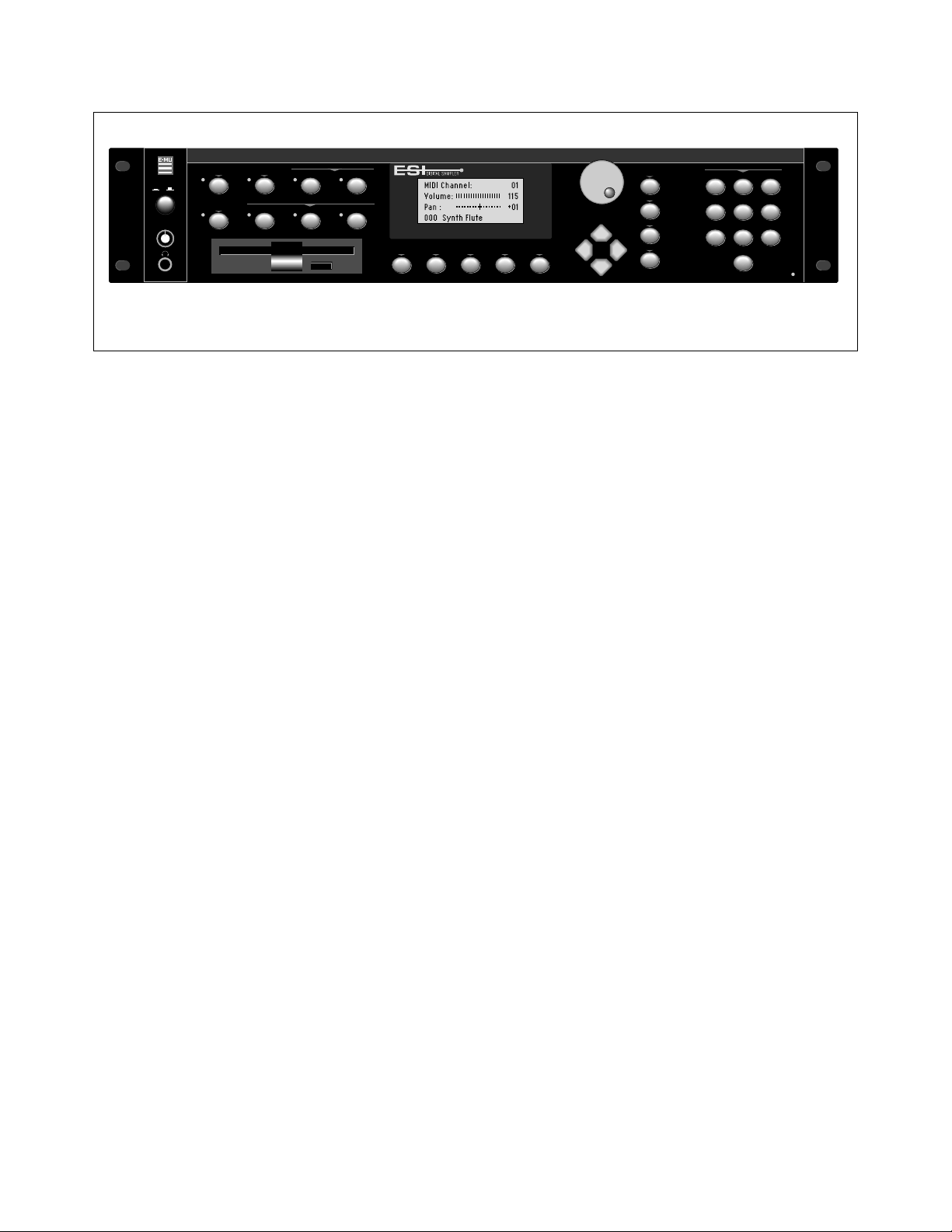
I
VOLUME
TRANSPOSE DIGITAL PROCESSINGSAMPLE MANAGEMENT
O
MULTIMODE
PRESET MANAGEMENT DYNAMIC PROCESINGPRESET DEFINITION
MASTER/GLOBAL
PRESET
SAMPLE
2000
DRIVE SELECT LOAD SAVE AUDITION TRIGGER MODE
INC/YES
DEC/NO
ENTER
ESCAPE
TRIGGERS
ABC
JKL
TUV
QZ
0
DEF
MNO
WXY
123
GHI
456
PRS
789
MIDI
ESI
ESI is the very latest in the long line of high quality and affordable E-mu
sampling products. ESI features 22.05 kHz and 44.1 kHz sampling rates
and 16-bit resolution for CD quality sound. Sampling can be performed
in either mono or true stereo. 64 channels of polyphony allow you to
stack sounds or create lush sequences without fear of channel “ripoff”.
The user-upgradable memory can be expanded to a maximum of 128
Mbytes using standard SIMM modules (Details and installation are
available at your E-mu dealer).
The ESI has full access to the huge library of sounds available from E-mu
and other sources. It is fully compatible with the legendary EIII and
EIIIX libraries, and can import Emax II and Akai S1000/S1100 banks. In
many cases, the ESI can import and convert programs faster than the
source unit!
The advanced features of the ESI make sampling easy. Samples can be
automatically truncated, normalized and placed on the keyboard as the
sample is taken. ESI also contains advanced tools such as Auto Correlation, Loop Compression and Crossfade Looping which allow even the
most difficult sounds to be easily looped.
Samples can be digitally spliced and mixed with other samples, and
dynamically controlled from the keyboard using velocity and positional
crossfading and switching functions. Advanced digital processing
features such as Sample Rate Conversion, Compressor, Digital Parametric Equalizer and Digital Tuning allow you to shape raw samples more
quickly and with greater precision than computer based systems.
Additional digital processing functions include: Time Compression and
Expansion, which shorten or lengthen the time of samples without
changing the pitch; and Doppler/Pan, which allows you to move
samples forward and backwards in space as well as from side to side.
The Sonic Enhancer adds brilliance and cut to a sample, helping it to
stand out in a mix.
4 ESI Operation Manual
Page 13

The ESI contains 19 different filters types for each of its 64 channels.
The digital filters are very “analog sounding” and implement the following filter types:
• 12, 24, or 36 dB/octave Lowpass filters with Resonance
• 2nd & 4th order Highpass filters with Resonance
• 2nd & 4th order Bandpass filters with Resonance
• Contrary Bandpass filter
• Three types of Swept EQ filters
• Three Phasers and one Flanger filter with Resonance
• Two morphing Vocal Formant filters
• Bottom Feeder
• Original ESi-32 24 dB/octave Lowpass filter
Modulation sources include three AHDSR envelope generators and a
multi-wave LFO per channel, as well as full MIDI modulation control
over virtually every parameter.
The ESI's unique Trigger Mode allows up to ten different samples to be
triggered from the front panel without connecting a keyboard, making it
an ideal tool for DJ's.
The ESI is 16 part multi-timbral which means you can create complex
sequences and sound effects.
Four polyphonic audio outputs with integral submix returns allow you
to process certain sounds separately and return them to the main
outputs without using up precious mixer channels. The Turbo option
card adds four additional submix outputs plus an Effects main output.
The ESI can access up to 999 samples per bank arranged in up to 256
presets. The integral 3.5" floppy disk drive provides a convenient means
of storing and loading banks. A built-in SCSI interface provides access to
external high density media such as hard disks, magneto-optical disks or
CD ROM.
A digital interface, available on the “Turbo” option, facilitates the transfer
of stereo digital audio between digital recorders, mixers, etc.
The Turbo option card also contains two stereo 24-bit digital effects
processors which add Reverb, Delay, Flanging and Distortion effects to
the ESI. Over 70 effects are implemented which can be applied on a per
MIDI channel basis or by keyboard “Zone”. Each preset can have its own
effect program when ESI is in Omni or Poly mode.
In developing ESI, we retained the logical and easy-to-use interface of
the industry-proven EIIIX and enhanced it with our state-of-the-art
G-chip and H-chip hardware. The G-chip allows smooth sample
transposition over a wide range while the H-chips retain the warm
character of analog filters.
ESI is an extremely powerful and reliable, seventh generation
instrument. We at E-mu Systems sincerely hope it will help you realize
and further your musical dreams.
Intro/Basic Setup 5
Page 14
Tip:
Inserting a standard mono plug
✱
halfway into either of the sub output jacks
allows you to sum into the main outputs
without a special cable. This is a handy
feature for those times when you run out of
mixer channels.
Tip:
The submix outputs use a “plug
✱
sensing” scheme which re-routes the signal
to the main outputs if a plug is not inserted.
Connecting to a Mixer
Main Outputs: The ESI has provisions for a variety of output connection schemes. The most common hookup is probably using the main
stereo outputs. Output level is -10 dBm (approximately 1-2 volts RMS).
Output impedance is 1K ohm.
Submix Outputs/Mix In: In addition to the main stereo outputs, the
ESI has an additional pair of submix outputs which can be used when
individual processing on specific instruments is desired. Any combination of channels can be programmed to appear at the submix output
pair. Any keyboard zone (key range) can also be assigned to the submix
pair using the Output Channel function in the Dynamic Processing
module. MIDI channels can be assigned to the submix pair using the
Multimode Mix function in the Master/Global module.
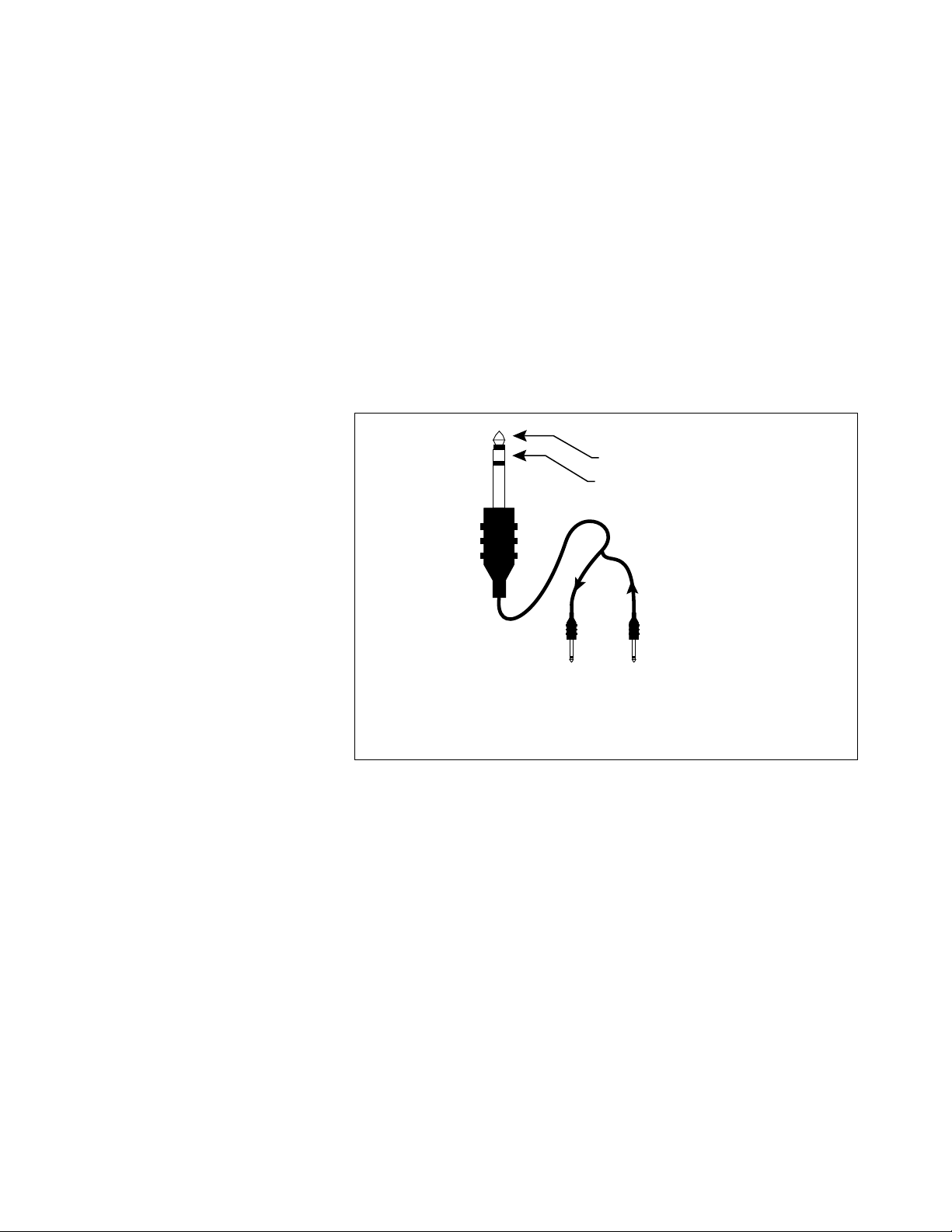
Sub Output
Return
(To Main Output)
Tip Ring
To Effect From Effect
SEND/RETURN CABLES
The Submix Outputs are stereo jacks with -10 dBm outputs on the tip of
the jack. Output impedance is 1K ohm. The ring of each submix jack is
a return input to the main outputs. By using a special cable shown
above, specific presets or MIDI channels can be externally processed and
then returned to the main mix.
Stereo Headphone Output: The headphone output is located on the left
side of the front panel and is capable of driving all types of stereo
headphones. The output level is controlled by the master volume
control.
Turbo Option Outputs: The optional Turbo card contains three additional output channel pairs: FX, Sub 2 and Sub 3. The stereo outputs are
accessed using a stereo plug adapter cable. The FX output is a duplicate
of the main outputs run through the effects processors. When MIDI
channels or Zones are programmed to “Main,” they appear at both the
FX and Main outputs. Submix outputs 2 and 3 incorporate “plug
sensing” which reroutes signals to the FX outputs if a plug is not inserted into the submix jack.
6 ESI Operation Manual
Page 15
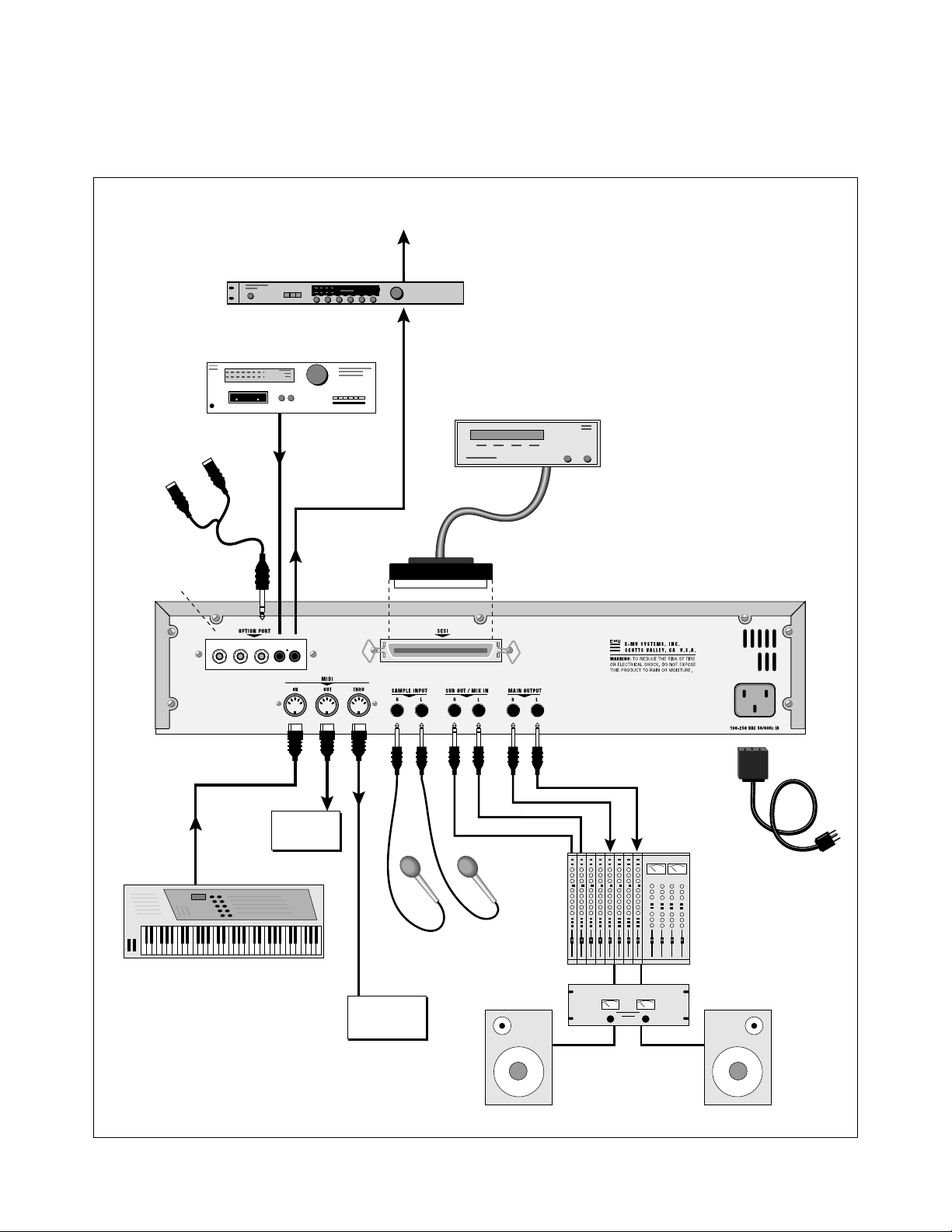
Connection Diagram
To Digital Mixer, DAT, etc.
Digital Effect Device
60 mS
Digital Input Device
DAT Recorder, etc.
Main FX Outputs
To Mixer
Turbo Option Card
Digital I/O
SCSI Device
SCSI
S/PDIF
FX
SUB 2SUB 3
IN OUT
TIP=LEFT RING=RIGHT
MIDI In
Sampler
MIDI Out
MIDI Controller
(MIDI Keyboard, Sequencer, etc.)
Other
Mic or Line Inputs
MIDI In
MIDI In
Additional
MIDI
Devices
Submix Out/Mix In
Mains
Power Amp
Power
Cord
Mixer
Intro/Basic Setup 7
Page 16

! Caution:
specifically for MIDI.
Only use cords designed
Sample Inputs
The two sample input jacks accept any low to high level input (microphone to line level). Input impedance is 10K. The gain of the sample
input preamplifier is controlled from the setup screen in the Sample
Management module. When in the Sample Management module the
sample inputs can be monitored from the main outputs or the headphone jack.
MIDI Connection
ESI provides a MIDI IN, a MIDI OUT and a MIDI THRU port.
• The MIDI IN port connects to the MIDI OUT port of an external
MIDI controller which could be a keyboard, a sequencer, MIDI
drum kit or whatever. Note that the ESI can only respond to
information that your controller transmits. If your MIDI keyboard
does not have velocity and pressure sensitivity, the ESI will not
respond to velocity and pressure.
• MIDI OUT can be connected to another MIDI instrument or
computer. The MIDI OUT jack is used to transmit MIDI sample
dump information (transfers sample data).
• MIDI THRU simply re-transmits any information received at the
MIDI IN port. Use cords that have been designed specifically for
MIDI. While regular 5 pin DIN cords may work, they are not
shielded correctly for MIDI use and may cause ground loops
between equipment.
! Caution:
Turbo Option Kit installed, please use only
low-profile SIMMs when adding RAM to
your ESI-4000.
If you plan on having the ESI
Footpedal and Footswitch Connection
Control pedals and footswitches can be connected if your MIDI
keyboard has inputs for them (most do). The MIDI keyboard translates
the controller movements into MIDI data which is received by ESI.
Controller data is sent over MIDI on a particular continuous controller
number assigned by your MIDI keyboard. ESI must be set to receive the
data using the same continuous controller number.
For more information, see MIDI Globals on page78.
110V / 220V Operation
The ESI may be used in either 110 volt or 220 volt environments at
either 50 Hz or 60 Hz. No change of voltage settings is required.
ESI automatically switches itself for 110 or 220 volt operation.
Digital I/O (Turbo option)
The optional Turbo card contains a digital interface which allows ESI to
transfer digital audio back and forth with other digital devices equipped
with S/PDIF digital I/O. Keeping the signal in the digital domain is
desirable to keep the signal to noise level as high as possible.
The digital input allows you to sample directly from a DAT recorder or
other digital device. The digital output reflects the data at the stereo
outputs of the ESI. See the Sample Management module and Main
Output Format (located under Special in the Master/Global menu) for
more information.
8 ESI Operation Manual
Page 17

Tip:
If you plan on expanding the
✱
memory beyond 4 MB, a mass storage
device is almost a necessity. When dealing
with large banks of up to 128 MB, a floppy
disk drive simply doesn't cut it, even for
back-up. A hard disk is an absolute must!
Furthermore, the extremely useful “Undo”
function will not work without a hard drive
attached.
SCSI
The SCSI connector is a high-speed parallel interface which is used to
connect the ESI with internal or external mass storage devices such as
hard disks or magneto-optical discs. The SCSI port can be used to link
the ESI with an external computer for extremely fast file transfers. The
ESI also supports SMDI (SCSI Musical Data Interchange protocol) which
allows transfer of samples over SCSI.
For more information on SCSI installation, see, “Using SCSI” in the
Appendix of this manual. Also refer to the manual that accompanies
your external SCSI device.
Following are step-by-step instructions on how to connect the ESI to a
SCSI hard disk or other SCSI storage device.
Connecting the ESI to an External, Unformatted Hard Disk
Important: Make sure that all power to the ESI and the SCSI device
is turned OFF.
1. Position the SCSI device and the ESI in a stable location. Hard
disk drives are particularly susceptible to shock and vibration. Make
sure that you position your hard disk where it won't be bumped or
moved while in use.
2. Connect the SCSI device to your ESI using a quality SCSI cable.
Make sure that the connectors are firmly mated and that the wire
“keepers” are locked in place.
! Caution:
the SCSI cable while power is applied to
either the ESI or the SCSI device. Doing so
may cause serious damage to both units!
✱
(Master/Global, Disk Utilities, 1) whenever
an external SCSI device does not appear in
the list of available devices.
NEVER connect or disconnect
Tip:
Use the “Mount Drives” utility
NOTE: There are two type of SCSI cables in common use: the
50-pin Centronics type and the 25-pin DB connector type. ESI uses
the Centronics type connector. If your external SCSI device uses the
DB connector you can use an adaptor cable to eliminate the
mismatch.
3. Set the SCSI ID of your external SCSI device to any number
other than 5 or 0. (5 is the default ID of the ESI, 0 is used by the
floppy drive). Consult the operation manual of your SCSI device for
this procedure.
4. Turn on the external SCSI device.
5. Apply power to the ESI.
6. Make sure the hard disk really is unformatted or contains
information you no longer want. Formatting a hard disk erases all
the data on it. Press the Load button. If the display reads, “No Valid
Drives” the drive isn't formatted. Continue on to step eight.
7. Format the hard disk. Press the Master/Global button, select Disk
Utilities (7), then Format (6). The display should read, “FORMAT
DISK”. Use the Data Entry Control to select your hard disk, then
press ENTER. The display asks, “Are You Sure?” Press the Inc/Yes
button to confirm. Formatting takes a few minutes. Time to take a
break.
Intro/Basic Setup 9
Page 18
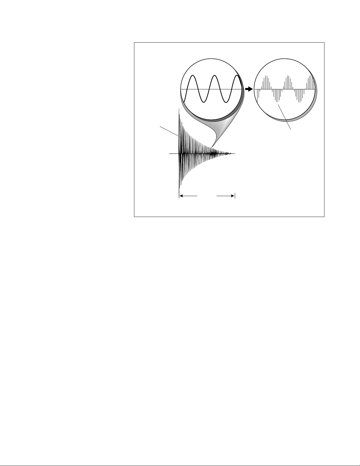
Sampling
Basics
Percussive Voice
1 second
Each vertical line
represents a sample.
Each sample takes
a "snapshot" of the
instantaneous signal level.
DIGITAL SAMPLING
stored in digital memory. Upon playback, the measurements are converted back into voltages to
reconstruct the original waveform.
Throughout this manual we will use the terms and concepts described
and defined below. Read through this section carefully, even if you don’t
retain it all. You can refer back periodically as you read through the
manual until you understand the basics and definitions.
The ESI is conceptually like a tape recorder. However, the recording
process is very different since the ESI digitally records into its computer
memory. Sounds for the ESI can be loaded via removable-media hard
disk, magneto-optical disk, CD-ROM using the SCSI interface; or
through the S/PDIF Digital interface; or even through the MIDI interface
using MIDI Sample Dump.
Computers can accept information only in the form of numbers, so the
ESI accepts audio signals coded into binary numbers. Samplers work by
examining (sampling) the incoming signal level at a very high rate
(44,100 times a second for compact discs), and sequentially recording
these different levels in memory. Once stored, these samples may be
played back (in the proper sequence, of course) to reconstruct the
original signal. For instance, if a two-second sound was being sampled at
44.1 kHz, it would require (2 X 44,100) or 88,200 samples to be
recorded. As you might imagine, shorter sounds require fewer samples.
The signal is repeatedly measured at a high rate and the measurements are
10 ESI Operation Manual
A sound can be manipulated once it has been recorded. Playing back the
samples in reverse order from which they were stored plays the sound
backwards. Playing back the samples at a faster rate than the rate at
which they were stored raises the pitch. Playing back at a slower rate
lowers the pitch, much like a tape recorder’s variable speed control.
Page 19

Definitions
How the ESI Organizes Sounds
Sure, you’re anxious to start coaxing wonderful sounds from the instrument—but the following is a necessary part of learning how to play the
ESI. It is important to understand how the ESI organizes sounds in order
to make best use of the instrument in the shortest possible time. Many
terms will be introduced now that show up later in the manual.
You can think of the ESI as resembling a collection of sound-organizing
modules, all contained within an the ESI bank. Pathways indicate how
information flows within the ESI. Let’s take a closer look at what makes
up this information, and how it is transferred from one section of the
instrument to another. We’ll start with individual samples, then work
our way through the system.
The Sample
Loading in any sound in mono or stereo creates a sample. A sample is
the raw material with which the ESI works. The total available sampling
time can be divided up any way you like—one long sample, lots of short
samples, a few medium samples, or any combination thereof.
The term sample commonly means two different things:
1. A digital recording of a complete sound, or
2. Each snapshot of the sound that makes up the complete sample.
Confusing? You bet! In this manual, we’ll assume sample means the
complete recorded sound unless indicated otherwise.
You can modify a raw sample in several ways:
• Transposition: A sample can be transposed up or down in pitch to
cover a particular range of the keyboard. By doing this, it is not
necessary to record a sample for every key.
• Digital Processing: In the ESI, Digital Processing might consist of
Looping a sample (allowing even short samples to play indefinitely),
Truncating (cutting off unneeded parts of a sample, thus saving
memory), or any of a number of digital processes that actually
change the raw sample data.
• Dynamic Processing: Just as synthesizers include signal processors
(filter, voltage-controlled amplifier, envelope generators, LFO, and
so on) to modify the sounds produced by the synth’s oscillators, the
ESI includes similar modules for modifying the sound of samples or
combinations of samples.
Intro/Basic Setup 11
Page 20
The Preset
As mentioned above, a sample can be assigned to a single note on the
keyboard, or transposed polyphonically to cover a wider keyboard
range. A preset is one entire keyboard setup. The process of assigning,
and optionally transposing, samples to specific ranges of the keyboard is
called making a preset. Making a preset is a three-step process:
1. Create the preset and give it a number and name. The bank can
hold up to 256 Presets (000-255).
2. Place samples to different keyboard ranges. For example, with
five samples you could assign each sample to cover one octave of a
five octave keyboard. A sample can be assigned more than once
within a given preset, and assigned to more than one preset.
3. Choose from a number of available options that further define
the preset. Some examples are: assigning samples to partially or
fully overlap other samples, thus producing doubling effects, or
assigning dynamic control to individual samples in a preset. You can
modify zone parameters, and set up MIDI and dynamic processing
parameters.
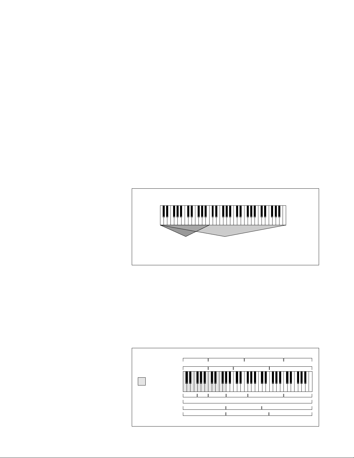
ZONE
= (Keyboard Range)
Any
Range
Entire
Kybd
The Zone
A particular range of the keyboard is called a zone. This zone can
include one or more samples and the zone’s boundaries need not be the
same as the boundaries of the samples contained in the zone. Zones free
you from having to think about where the actual samples are assigned.
You just select a range of keyboard (a zone) and go!
As an example, suppose you wanted to set the velocity response for the
entire keyboard. You would first select the zone range by playing the
lowest and highest keys when prompted by the ESI. Next you would set
the velocity response (in the Dynamic Processing module). Done.
Primary Samples
Secondary Samples
Sample 05
Sample 01
Sample 06
Sample 02 Sample 03 Sample 04
Sample 07 Sample 08
12 ESI Operation Manual
= Copied Zone
Fc
Vel -> Level
Tuning
Pan
Page 21
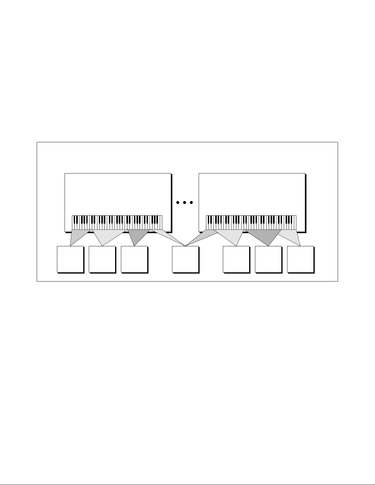
THE BANK
(Holds up to 256 Presets)
Now, suppose you wanted just the lower half of the keyboard to have
increased velocity response. You would simply select a zone for the
lower half of the keyboard, then change the velocity settings as desired.
When you copy a zone, the appropriate samples will be picked up along
with the Dynamic Processing parameters.
The Bank
The memory bank contains samples, zones and presets. Everything.
Consider the bank as the central storehouse for all of the ESI’s data.
Although the memory is volatile, meaning that the data disappears when
you turn off power, all bank data can be saved permanently to the hard
disk drive or other media to keep a record of your work.
Preset 000
All Preset Definition Parameters
All Dynamic Processing Parameters
(One entire keyboard setup)
Sample
Sound
Data
Loop Points
Sample Sample Sample
Sound
Data
Loop Points
Sound
Data
Loop Points
THE BANK All the data loaded into the ESI is called the Bank. Each individual keyboard setup is
called a Preset. Individual Samples can be shared among presets.
The Internal Drive
A disk drive is a memory storage device that stores banks of data. The
standard ESI has a built-in floppy disk drive which can be used to load
and store bank data. However, other types of drives, as described later,
can connect to the ESI to provide sound storage.
Sound
Data
Loop Points
Preset 255
All Preset Definition Parameters
All Dynamic Processing Parameters
(One entire keyboard setup)
Sample Sample Sample
Sound
Data
Loop Points
Sound
Data
Loop Points
Sound
Loop Points
Data
Tip:
Use the “Mount Drives” utility
✱
(Master/Global, Disk Utilities, 1) whenever
an external SCSI device does not appear in
the list of available devices.
• Floppy Disk Drive (Drive 0): The floppy disk drive accommodates
3.5", double-sided, high-density (1.4 MB) floppy disks. The floppy
drive on the ESI is used mainly as a convenient way to load and save
small sound banks. When a bank size larger than 2 MB is used,
(which requires 2 disks) the floppy disk becomes impractical for
backing-up sound data.
• Iomega 100 MB Zip Drive: The ESI is also available with an
internal 100 MB Zip removable disk drive in place of the floppy disk
drive. Treat the internal Zip with care, just as you would any other
hard disk drive. To use: simply insert a disk into the drive with the
label side up.
To eject the disk: press the button on the right.
Intro/Basic Setup 13
Page 22

Tip:
The ESI can only load floppy disks
✱
which were created on the ESI. It can load
hard disk data created on the EIII, EIIIX,
Emax II or the Akai S1000/S1100.
Tip:
Use the “Mount Drives” utility
✱
whenever an external SCSI device does not
appear in the list of available devices.
External Drives
The ESI has a SCSI (Small Computer Systems Interface) connector on
the rear panel. This interface is commonly used in the computer industry, so that many devices made to work with computers—particularly
mass storage devices—will also work with the ESI. Here are some of the
types of mass storage devices that can plug into the ESI’s SCSI connector.
• Hard Disk Drive: A hard disk provides the advantages of much
higher memory capacity and far faster access time. Transferring data
to and from the ESI is quite straightforward. However, you cannot
remove a hard disk and replace it with another one—the disk is a
permanent part of the drive. There are three main cautions involved
with hard disks:
1. Hard disks are sensitive to extreme mechanical shocks. If your hard
disk falls off a keyboard stand, chances are the hard disk will be
damaged.
2. Make sure power is not interrupted when you write data to the hard
disk.
3. Hard disks have reached a very high level of reliability. However,
they can fail from time to time (as can any part of a computer), so
any data should be backed up periodically and regularly on some
other medium.
• Removable-media Hard Disk Drives: These are similar to normal
hard disk drives except that the disk itself can be removed and
replaced with another disk. Disk densities can range from 44 Mbytes
to over 270 Mbytes per platter. Removable-media hard disk drives
allow you to build a sound library of unlimited size and are quite
handy for transferring sounds between machines. They're also
perfect for backups.
• CD-ROM Drive: A CD-ROM is a playback-only (data cannot be
written to it) mass storage memory device whose capacity is
approximately 660 Megabytes. Many high-quality and low cost
CD-ROM libraries are available from several companies (E-mu
Systems, Inc., Northstar, Sound Ideas, Q-Up Arts). These can be
loaded into the bank as easily as you would load from a hard disk.
• Magneto-Optical Drive: Basically a read/writable CD, these high
speed, high density storage devices are currently the hottest thing
around for storing large amounts of sound data. Typically a
magneto-optical drive can hold upwards of 300 Mb per side and the
removable cartridges can be used over and over. Disk access time is
comparable to a normal hard disk, and is sometimes even faster!
Advantages: High-speed, high-density, reliable, removable.
Disadvantage: High cost (although prices are dropping fast).
14 ESI Operation Manual
Page 23

Additional
Definitions
The Primary and Secondary Layers
An ESI key provides for two channels. These contain the primary and
secondary layers. For example, the primary layer might be a sample of a
guitar note and the secondary layer a detuned version of the same guitar
note. When played together, you hear chorusing. Also, a preset contains
information about how the keyboard dynamics affect the primary and
secondary layers. As an example, the primary layer could be a sample of
a drum hit played softly, and the secondary of a drum hit played loudly.
Thus, playing the keyboard softly would play the primary layer, and
playing the keyboard more forcefully would play the secondary layer.
The Current Preset
When you load a bank, a preset will be ready to play and the display will
show the preset number. This is the current preset. If you select another
preset, or create a preset, that will become the current preset.
The Current Sample
When a bank is first loaded, the current sample defaults to Sample 001.
Whenever you record, load, or select a sample, it becomes the current
sample. Thereafter, when you load a bank, the default sample is the
current sample at the time you last saved that bank. For example, if
sample 029 was the current sample the last time you saved the bank,
then the next time you load the bank the current sample defaults to
sample 029. You can always hear the current sample by pressing the
audition button or entering the Digital Processing module.
Tip:
If a module is already active and
✱
you are finished with one submodule, you do
not need to re-activate the module - just key
in the new submodule number.
Modules
A module controls a particular set of functions in the ESI. There are six
main modules: Master/Global, Preset Management, Preset Definition,
Sample Management, Digital Processing and Dynamic Processing.
• Activating a Module and the Module Identifier: To work with a
module, you must first activate it. Press the button associated with
the desired module. The display will then show the Module
Identifier and invite you to select a submodule.
• Submodule: Each module contains several numbered submodules
that set controls for additional functions. There are two ways to
select a submodule within the module. You can move the Data Entry
Control until the display shows the desired submodule, then press
ENTER. As you work with the ESI, though, you will start to
memorize the submodule numbers and will probably find it faster to
simply key in the appropriate submodule number using the numeric
keypad. When using the keypad, it is not necessary to press ENTER.
Pressing either the module button or the Escape button will return
you to the preset selection screen.
Intro/Basic Setup 15
Page 24

Saving
The bank only retains data for as long as the ESI is plugged in and
turned on. Of course, we don’t expect you to leave the thing on all the
time, which brings us to the subject of saving data.
Pressing the SAVE button on the Control Panel shuttles all the bank data
(samples and presets) to the drive of your choice. A hard disk permanently stores data so that even after turning off the ESI, the disk will
contain a record of your work.
IF YOU DO NOT SAVE A BANK, ALL BANK DATA WILL BE
LOST WHEN YOU TURN OFF THE MACHINE.
Do not wait until the end of a session to save. Save your work periodically in case of power failure or some other unforeseen circumstance that
might erase the bank’s memory. Floppy disks and hard disks are not
infallible. All hard disk banks should be backed up periodically to
another hard disk or other media. Should you improve the preset or
sample later, you can always replace the original with the revised version. And if something goes wrong, the original will still be available to
save you the ordeal of starting from scratch. Whenever you have done
enough work that you would hate to lose it, back it up!
Since the disk contains a record of the bank data, loading the disk back
into the bank transfers all the sample and preset data into the bank. This
will replace the existing bank data, if any.
Default
A default setting is what we’ve judged to be a useful initial setting, and
remains in effect until you change it. For example, if you create a new
preset, portamento will default to 0 seconds (off). Had it defaulted to
some higher value, all new presets would have portamento applied.
The Cursor
The cursor is that small flashing line on the display. It sits under the
number or letter that will be altered if you enter data. Entering a new
value will overwrite the number or letter above the cursor, whereupon
the cursor will move on to the next number or letter (if applicable). If
the ESI is expecting a two or three-digit number, in most cases you must
enter all the required digits even if some of these are zeroes (called
leading zeroes). For example, if the ESI is expecting a three-digit number
and you want to enter 8, you would enter 008. If it is expecting a singledigit number, entering 8 would be sufficient.
16 ESI Operation Manual
Data Entry Control & Increment/Decrement Buttons
In virtually all instances where the Data Entry Control selects options,
the Increment (INC/YES) and Decrement (DEC/NO) switches duplicate
the Data Entry Control. Press INC/YES to increase a value, or DEC/NO
to decrease.
Page 25

Selecting
When the instructions say to select an option, you can use whatever
method is most comfortable for you: the Data Entry Control, the Increment/Decrement buttons, the numeric keypad (if applicable) and, when
naming, or selecting pitches, the keyboard keys. Some functions do not
implement all these options; you can’t go wrong by trying, though. If a
function doesn’t respond to the numeric keypad, for instance, then
pressing the keypad will have no effect. Use the Data Entry Control or
the INC/DEC buttons instead.
The Big Re-Cap
• A sample is a raw sound that is loaded into the bank.
• To create a new preset, make sure you have all the samples required
for the preset in the bank, number and name a preset, then assign
combinations of samples from the bank to specific sections of the
keyboard. By specifying one or more of these samples (or portions
thereof) as a zone, the zone may then be processed by the ESI’s
dynamic signal processors.
• After arranging a bank, it can be saved to one or more drives.
• Since loading from a hard disk fills the bank with samples and
presets, you can group these samples into new presets, process the
samples contained in particular zones, or alter existing presets.
Intro/Basic Setup 17
Page 26

18 ESI Operation Manual
Page 27

2 Controls
Master Volume ....................... 21
Data Entry Control ................ 21
INC/DEC Buttons .................. 21
Ten Key Pad ........................... 21
Escape .................................... 21
Enter ...................................... 21
Cursor/Page............................ 22
Preset Selection...................... 22
Load Bank .............................. 23
Save Bank ............................... 23
Drive Select ............................ 24
Audition ................................. 24
Trigger Mode .......................... 24
Multimode.............................. 25
Transpose ............................... 25
Controls 19
Page 28

20 ESI Operation Manual
Page 29

Master
Volume
Data Entry
Control
Inc/Dec
Buttons
The Master Volume Knob controls the volume of every audio output on
the ESI including the submix and headphone outputs. The master
volume knob is a digital control. For maximum dynamic range it should
be kept near the maximum position.
Using the Data Entry Control is the most common way to change
parameter values on the ESI. Moving the control changes either the data
over the flashing cursor or scrolls through options in the display.
In all ESI menus where the data entry control selects options, the
Increment (INC/YES) and Decrement (DEC/NO) Buttons duplicate the
function of the Data Entry Control. The increment/decrement buttons
can be used when a finer degree of control is required. They can also be
used for selecting Yes or No.
Ten Key Pad
Escape
Enter
The Ten Key Pad is used to enter data in precise amounts. For instance,
if you wanted to jump to preset 10, enter 010 on the ten key pad and
the new preset number will be instantly selected, eliminating the process
of finding the number with the data entry control and then pressing
Enter.
The Escape button lets you back out of a module by one menu each time
the button is pressed. It can also be used anytime you do not want to
execute a particular function (bail out). In the Sample Management
module, pressing the Escape button terminates the sampling process.
A flashing Enter LED means that the ESI wants you to do something.
Data may need to be entered, or the ESI may be waiting for you to press
the Enter button to activate a particular operation. If the Enter LED is lit
steadily, pressing Enter is optional. Doing so will exit you from the
function and return you to the module identifier. You also have the
option of going directly to another function within the module.
Controls 21
Page 30

Cursor/Page
The Cursor is a small flashing line that appears in the display window
under the data that is currently being edited. The Cursor/Page buttons
are used to move the cursor around in the display. The buttons are
shaped like arrows which point in the direction of movement. In many
cases a particular function will have more options than will fit on a
single page of the display. In this case the right and left arrow buttons
become the page selects, allowing you to move through the various
pages of the display.
The Cursor/Page buttons perform the following functions:
1. Moving the cursor. To move the flashing cursor line in a particular
direction in order to select a different function, simply press the
corresponding cursor key.
2. Selecting the display page. In many submodules, a single screen of
the LCD cannot display all the available parameters. Arrows (<- ->)
in the display indicate that there are additional screens which may
be viewed by pressing the corresponding cursor button.
Tip:
The cursor buttons can be used to
✱
select presets only when the ESI is in Omni
or Poly modes.
Preset
Selection
3. Selecting presets. When no modules are selected, and the cursor is
placed under the preset number, presets may be incremented or
decremented by pressing the left and right cursor buttons. This
method is useful for live performance - arrange your presets in the
desired order, and step through them as needed.
4. Adding or deleting a space when naming. A quick and easy way to
add or delete a space when naming samples or presets is to use the
left and right cursor keys. The up key adds a space and the down
key deletes a space.
5. Selecting zero crossing points when editing samples. When
editing samples in the Digital Processing module, the left and right
cursor buttons can be used to select points where the waveform
crosses the zero axis.
Selecting the Current Preset
With no modules active, the display shows the Current Preset name
and number on line 1 of the display. The blinking cursor appears under
the preset number’s first digit. There are five ways to change the current
preset:
1. Enter a three-digit number with the keypad. If you enter a number for which there is no preset, the lower display line shows the
illegal preset number and says “Empty Preset.” Try again.
22 ESI Operation Manual
2. Move the data entry control or the increment buttons. The top
display line continues to show the current preset, but the lower line
will scroll through the available presets as you move the data entry
control. When the lower line shows the preset that you want as the
current preset, press ENTER.
3. Increment or decrement the Current Preset (as displayed in the
top line) with the left and right cursor buttons. This method is
useful for live performance—arrange your presets in the desired
order, and step through them as needed.
Page 31

Load Bank
4. Use a MIDI footswitch to advance through the presets.
5. Use a MIDI program change command. Presets 000-127 can be
accessed via a MIDI program change command. Presets 128-255 can
be accessed using a MIDI bank select command, followed by a
program change. See the MIDI Implementation Chart in the Appendix.
To see the current preset number at any time, de-activate any active
module and look at the display.
A bank consists of presets and samples. The Load function loads this
data into the ESI's memory bank from the floppy disk, hard disk or
other external SCSI device.
1. Press Load.
2. If necessary, select the drive containing the bank to be loaded.
The ESI defaults to the current drive. If you want to choose a
different drive, place the cursor under the drive number in line two,
select the appropriate drive and press ENTER.
LOAD BANK from
D1 Internal HD
Save Bank
Select a Bank
3. Select the bank number that contains the bank to be loaded,
then press ENTER. The display will say: Loading Bank. After a few
seconds, the bank will be loaded. The display will revert to the
preset selection screen.
A bank consists of presets and samples. The Save function saves this data
from the ESI's memory bank to the floppy disk, hard disk or other
external SCSI device.
1. Press Save.
2. If necessary, select the drive to which the bank will be saved.
The ESI saves the bank to the current drive by default. If you want
to choose a different drive, place the cursor under the drive number
in line two, select the appropriate drive and press ENTER.
SAVE BANK into
D1 Internal HD
Select a Drive
3. Select the number to which the bank will be saved, then press
ENTER. The approximate size of the bank will be displayed on line
four. Empty banks are indicated as such, along with their bank
number on line three. Or, you can overwrite an existing bank.
Controls 23
Page 32

Drive Select
! Caution:
the drive select screen, such as a computer
or another sampler on the SCSI bus. Please
note that only SCSI storage devices can be
selected.
All SCSI devices are listed in
SAVE BANK into
D1 Internal HD
B00 Stereo Grand
7.8MB in Bank
4. Press ENTER to save the bank. A bar graph appears in the display
showing the progress of the save operation. The display reverts to
the preset selection screen when the save operation is completed.
Use the Drive Select Button to select which storage device to use when
loading or saving. The ESI may have an internal hard disk and/or several
external SCSI devices connected.
1. Press Drive Select. The display shows:
DRIVE SELECT
D1 Sony SMO-C501
Select a Drive
2. Use the Data Entry Control or 10 Key Pad to select the desired
drive, then press ENTER. Any subsequent Load or Save operations
will now use the selected drive.
Audition
Trigger Mode
The Audition button allows you to play the currently selected sample, at
its original pitch, directly from the front panel without having to connect
a keyboard or other controller. (The current sample is selected in the
Digital Processing module.) When you are in the Load Sample
submodule, the Audition button allows you to preview samples directly
off the hard disk without having to first load them.
Note: If you are auditioning from the current RAM bank you hear the audition
in stereo. If you are auditioning from the disk, you hear the audition in mono.
When Trigger Mode is activated, the buttons of the ten key pad become
sound trigger buttons which can access any ten notes in the current
preset. This allows the ESI to be used as a stand-alone sample playback
unit. In Trigger Mode, the LED next to the trigger button illuminates and
all ESI functions operate normally, except that the ten key pad is now
used exclusively for triggering sounds.
The Trigger Buttons are programmed in the Master/Global module,
Special (8), Trigger Buttons (7).
24 ESI Operation Manual
Page 33

Multimode
Tip:
Setting the preset to “Unassigned”
✱
also blocks incoming preset changes on that
channel.
The Multimode Button puts the ESI into Multimode, where it can
receive on up to 16 MIDI channels at once. Multimode is used for multitimbral sequencing and when using a keyboard that can transmit on
more than one MIDI channel at a time. The Multimode screen is where
you assign presets to MIDI channels for multi-timbral sequencing. You
can also set the volume and stereo pan position for each channel's
preset.
1. Press Multimode. The display shows:
MIDI CHANNEL: 01
Volume: 127
Pan-∆ +00
000 Synth Flute
2. Use the cursor buttons to select one of the following parameters
to edit. The volume, pan and preset can be programmed for each of
the 16 MIDI channels. Use the data entry control or INC/DEC
buttons to change the MIDI channel, Volume or Pan setting. If you
do not want the ESI to respond to certain MIDI channels, set the
preset for those channels to “Unassigned” which is located just
below preset 000.
Transpose
MIDI CHANNEL: 02
Volume: 116
Pan-∆ -01
Unassigned
This function transposes the entire ESI in half-step intervals up to
± one octave. When in multimode, all channels will be transposed.
When the ESI is in Transpose mode, the Transpose LED will be lit
steadily. A new transposition can be selected at any time, regardless of
whether or not the Transpose LED is lit.
Some applications are:
• Use one key's fingerings in a different key. Modulate to a different
key without having to use different fingerings.
• Use transpose to easily reach hidden zones that lie beyond the ends
of the physical keyboard.
1. Press and hold Transpose. Its LED flashes, and the display shows:
TRANSPOSE
Play a Key
Controls 25
Page 34

2. While holding Transpose, select the desired transposition
interval. All transpositions are referenced to C2, the second C from
the left hand side of the keyboard.
Some examples are:
• To transpose down one octave, press C1.
• To transpose up one octave, press C3.
• To transpose up a fourth, press F2.
Note that pressing keys C#3-C4, C#4-C5, or C#5-C6 will, in each case,
produce the same effect as pressing keys C#2-C3.
3. While holding Transpose, check the display to confirm the
transposition interval. Upward transpositions are indicated with a
+ symbol, downward transpositions with a - symbol. For example, if
the ESI is transposed up a fifth, the display will show:
TRANSPOSE
+G
Play a Key
4. Release Transpose to retain the transposition. The Transpose LED
stays lit to remind you that the ESI is transposed.
5. To cancel the transposition, press and hold Transpose and press
C2. Display line three will go blank. Release Transpose and the LED
should now be off.
26 ESI Operation Manual
Page 35

3 Guided Tours
1. Basics ................................. 29
2. Selecting Zones .................. 33
3. Dynamic Processing ........... 35
4. Realtime Controls .............. 42
5. Sampling ............................ 45
6. Digital Processing .............. 47
7. Managing the Bank ............ 54
8. On Your Own ..................... 54
Guided Tours 27
Page 36

28 ESI Operation Manual
Page 37

Tour 1:
The Basics
Tip:
ESI banks usually do not fit on a
✱
single floppy disk. To load multiple disk
banks, insert the first disk, then replace it
with the next disk when prompted by the ESI.
Welcome to the Guided Tours! If you have just met the ESI for the first
time, we suggest that you follow these tours until you complete the
Guided Tours section. This will get you up and running on the ESI in
the fastest possible time. Also, you’ll learn some tricks in this section
that will come in handy as you play and become more familiar with the
ESI. This tour covers how to:
• Load and Save to Floppy Disks
• Select Different Presets within the Bank
• Tune the ESI to Other Instruments
• Transpose the Keyboard
Loading a Bank from Floppy Disks
1. Press the Load button. Position the cursor under the drive number
in line two. Select the floppy drive using the Data Entry Control.
2. Insert the first floppy disk of the selected bank and press
ENTER. The display will say: Loading Bank. Remember that loading
in a new bank erases the currently loaded bank, so always think
twice before pressing ENTER to load the bank. (Since ESI banks can
be quite large, it may require several floppy disks to hold an entire
bank. Multiple floppy disks must be inserted in the proper order.
That's why it's a good idea to label them numerically.)
Play the sounds from the newly loaded disks.
Saving Data to a Floppy Disk
The floppy disk drive can be used to make permanent backups of your
work. This can be a time consuming process, especially with large bank
sizes and is best handled using a hard disk. If you do not have a hard
disk installed in, or connected to your ESI, you can back up your work
to floppies. In preparation, you should try to have at least five ESI
formatted, double-sided, high-density, 3.5" diskettes on hand.
To Format a Floppy Disk:
Before a floppy disk can be used by the ESI, it must be formatted using
the Format Disk function.
1. Activate the Master/Global module.
2. Select Disk Utilities (7), Format Disk (6).
3. Select the floppy using the data entry control and press ENTER.
Position the cursor under the drive number in line two. The ESI will
normally default to the floppy drive.
4. Insert a floppy disk into the drive and press Yes to format.
Formatting a disk will erase all information on the disk.
Once the format is complete, the ESI asks if you want to format another
disk. Continue to format at least four more disks
5. The display asks, “Format Another?” Insert the next disk and press
Yes to continue formatting. After formatting the last disk, press No.
Guided Tours 29
Page 38

Saving Data to a Floppy Disk:
1. Press the Save button. Position the cursor under the drive
number in line two. Select the floppy drive using the Data Entry
Control.
2. Insert a floppy disk and press ENTER. The display will say,
“Saving Bank”. If the save requires multiple disks, the display
prompts you to insert the next disk. Once the save operation is
completed, the display returns to the main screen. If the save
required multiple disks, make sure to label them numerically.
Using an External Hard Disk
You may connect an external hard disk, to load and save data, to the ESI
external SCSI port. Before connecting any SCSI device, always make sure
that power to the ESI and the external SCSI device is turned Off.
To Connect an External Hard Disk Drive
1. Turn all power Off to the ESI and the external drive.
2. Connect the external drive to the ESI using the proper type of
SCSI cable. This will most likely be a 50-pin, male to male
Centronics type. (Please read the SCSI section in this manual for
important information on SCSI connections.)
3. Turn on the external SCSI device BEFORE the ESI.
4. Turn on the ESI.
To Format a Hard Disk Drive
Like a floppy disk, a hard disk must also be formatted before it can be
used to store information.
1. Activate the Master/Global module.
2. Select Disk Utilities (7), Format Disk (6).
3. Select the hard disk using the data entry control and press
ENTER. Your hard disk should appear in the list of available drives.
If the hard disk is not listed, use Disk Utilities, 1 to Mount Drive.
After Mounting, the hard disk should appear in the list of available
drives. If it does not appear, turn everything Off, then read the SCSI
chapter in this manual for possible solutions.
4. Consider the consequences of your action. Formatting the hard
disk will erase everything on that disk. The display will inquire if
you want to do this.
5. Press Yes to continue the formatting procedure or No to cancel
the operation and return to the Module Identifier. Formatting a
hard disk can take quite some time, depending on the size of the
disk. Take a break.
30 ESI Operation Manual
Saving Data to a Hard Disk
The hard disk drive is used to make permanent backups of your work.
Although you can back up your work to floppy disks, the capacity of the
floppy drive is too small to be efficient. Only the hard disk (or its
equivalent) should be used for sound storage.
Page 39

To Save a Bank to Disk:
1. Press the Save button. Position the cursor under the drive
number in line two. Select the disk drive using the data entry
control. Press ENTER.
2. Use the Data entry control to select an Empty Bank. Empty
banks are indicated as such, along with their bank number on line
three. Saving to a non-empty bank erases the bank that was previously saved there.
3. Press ENTER to save the bank. The display will revert to the preset
selection screen.
Loading a Bank from a Hard Disk
1. Press the Load button. The display says: Load Bank, and shows the
name and number of the current bank.
Tip:
See Master/Global, Disk Utilities
✱
and the SCSI section of this manual for
important information about hard disk
drives.
2. Select the desired bank. Use the Data Entry Control to scroll
through the available hard disk banks. Stop when you find the bank
you want.
3. Press ENTER.
• An alternate method of loading a hard disk bank is to press
Load, then type in the number of the bank using the numeric
keypad. The display will show the current preset number and name.
The cursor will flash underneath the first digit. Start playing the
keyboard and adjust the master volume Data Entry Control for a
comfortable listening level.
To check out the various presets within the bank, read on.
Selecting Different Presets
The bank you just loaded contains several presets. To call up a new
current preset, use the up/down cursor buttons to position the cursor
under the preset number, then use the keypad underneath the display.
Note that leading zeroes must be entered for preset numbers (for example, type 0, 0 and 2, not just 2, to call up preset 002). Now type the
number of the desired preset on the keypad. The entered preset number
these will replace the numbers indicated by the flashing cursor.
If you enter a number for which there is no preset, the display lists the
entered preset number followed by “Empty Preset.” Try again.
Tip:
Use the “Mount Drives” utility
✱
(Master/Global, Disk Utilities, 1) whenever
an external SCSI device does not appear in
the list of available devices.
To scroll through the presets available in the bank, turn the Data Entry
Control. The various preset names will scroll on the lower display line.
When this line shows the desired preset, press ENTER to make that the
current preset. This is an alternative preset selection method.
Yet another method is to use the left and right cursor buttons to increment or decrement through the presets. This method allows you to
arrange your presets in the proper order, then access them sequentially
with a single press of a button.
When you’re ready to check out some more sounds, proceed.
Guided Tours 31
Page 40

Tuning the ESI to Other Instruments
Select the Master/Globals module. Choose sub-module Master Tune (1).
This function demonstrates how ESI uses the Data Entry Control to
adjust a parameter. Play the keyboard while adjusting the Data Entry
Control to change the overall tuning.
Transposing the Keyboard
Refer to the Transpose button. While holding the transpose button, play
a key on the keyboard in the lower two octaves. The second C from the
bottom (C2) corresponds to normal or no transposition. All transpositions are based from this C2 key. For example, pressing the G key above
C2 will transpose the keyboard up a perfect fifth. If the keyboard has
been transposed, the transpose LED will stay lit. Press and hold the
transpose button while pressing C2 to return to normal transposition.
32 ESI Operation Manual
Page 41

Tour 2:
Selecting
The Current Sample & Current Zone
The ESI has two modules dedicated exclusively to processing samples
within a preset: Sample Management and Digital Processing. Each
sample stored in a bank can be processed by the Digital Processing
module independently. Therefore, we need a way to specify the current
sample, which is the individual sample to be processed.
Zones
The concept of the current sample is important. To process one sample
out of a preset, select one sample to be the current sample, and process
it.
To Identify Which Keyboard Keys Belong to Which
Sample:
1. Activate the Preset Definition module.
2. Select Edit Assignment (2).
Sample
Number
& Name
3. Play a key on the keyboard. Line two shows the preset number
and the last key pressed. Line three shows the primary sample
assigned to the key, and the fourth line shows the secondary sample,
if any, assigned to the key. As you run your fingers up and down the
keyboard, the primary and or secondary sample numbers will
change indicating the keyboard range of those samples. You can also
move the Data Entry control knob to show you the sample boundaries.
EDIT ASSIGNMENT
000 pri D2
001 Sample Name
No Secondary Sample
4. Choose a zone and press ENTER. The display now shows the
range of the current zone on the upper line of the display. Don’t play
any keys but press ENTER again. Now the display shows something
like this, where XX is the name of the key (such as D2).
EDIT ASSIGNMENT
Zone: XX to XX
Select High Key
Guided Tours 33
Page 42

Specifying the Zone of the Dynamic Processing Module
Zones are sections of the keyboard which can be selected to apply
Dynamic Processing parameters or to be copied, erased or loaded from
another preset. A copied zone contains samples as well as dynamic
parameters. A zone can be one key or the entire keyboard range.
Now that we know how many samples there are in the preset, and the
range covered by each sample, let’s specify a range of keys (defined as a
"zone") to be altered by the Dynamic Processing Module. Refer to Tour
3, Dynamic Processing for information about dynamic processing. This
section describes how to specify a zone to be affected, starting with the
lowest key.
1. Activate the Dynamic Processing module.
2. Choose Select Zone (0).
3. Specify the range of the zone. The display instructs you to “Select
Low Key.” Press the lowest key on the keyboard, then press the
ENTER button (whose LED is now flashing). The display then
instructs you to “Select High Key”. Press a key on the keyboard near
the top of the keyboard, then press ENTER. The display now shows
the current zone and prompts you to “Select a Submodule”.
At this point, you can begin modifying the sounds in the bank with the
Dynamic Processing module. The assigned current zone will remain as is
until you either change the current zone assignment, change presets, or
load another bank. If you switch between modules, the current zone
remains as assigned (unless you select the Digital Processing Module,
which will be a subject of a later tour).
Before proceeding, look over Dynamic Processing, 0. Select Zone to help
reinforce what you’ve learned. Now that you know what a zone is and
how to specify it, we’ve reached the end of this tour. Feel free to come
back any time to refresh your memory. In the next tour, we’ll see how to
modify samples with the Dynamic Processing section.
34 ESI Operation Manual
1. Select Low Key, Enter 2. Select High Key, Enter
3. Select a Submodule & Modify Zone
Any range of the keyboard can be a zone. Select the low and high keys which define the zone, then
select the Dynamic Processing parameter to be modified.
Page 43

Tour 3:
Dynamic
Processing
The Dynamic Processing module consists of several interesting sound
processing functions. Let’s start with the Filter and VCA sections, as they
are among the most important.
The VCA function contains a Voltage Controlled Amplifier that controls
the amplitude envelope of a sound. The filter function contains a Voltage
Controlled Filter that controls the timbre of a sound. (Note: The voltage
controlled filters and amplifiers are actually implemented digitally.)
Working with the Filter
A filter is a device which allows you to remove certain components of a
sound depending on its frequency. For example, a Low Pass Filter, like
the one in ESI, lets the low frequencies pass and removes only the high
frequencies.
Tip:
When the filter cutoff is set to 0 Hz,
✱
the sound will be completely cut off. The
initial filter cutoff and all filter Fc modulators
ADD algebraically to determine the actual Fc.
If you are not getting sound, adjust the initial
Fc or reduce the amount of modulation.
Careful adjustment of the filter parameters is
the secret of getting great sounds.
100
80
60
40
Amplitude
20
Output of Filter
40 80 160 360 720 1440 2880
Cutoff Frequency
...
Frequency
The point at which the frequencies begin to be cut is called the Cutoff
Frequency (or Fc for short). A filter that lets only the high frequencies
pass would be called a High Pass filter. Using a filter, we now have a way
to control the harmonic content of a sampled sound. As it turns out, a
low pass filter can simulate the response of many natural sounds.
For example, when a piano string is struck by its hammer, there are
initially a lot of high frequencies present. If the same note is played
softer, there will be fewer of the high frequencies generated by the string.
We can simulate this effect by routing the velocity of the keyboard to
control the amount of high frequencies that the low pass filter lets
through. The result is expressive, natural control over the sound.
Low Q Med Q High Q
Amplitude
Frequency
Turning up the “Q” will emphasize the
frequencies around the cutoff point.
The VCF envelope generator is used to control the cutoff frequency of
the low pass filter. This allows the frequency content to be varied
dynamically over the course of the note. Dynamic filtering coupled with
different samples makes for endless possibilities in the final sound.
Another control on the low pass filter is called Q or resonance. Turning
up the Q of the filter tends to emphasize the frequencies around the
cutoff frequency. In terms of sound, frequencies around the cutoff will
tend to “ring” with high Q settings. If the filter is swept back and forth
slowly with a high Q, various overtones will be “picked out” of the
sound and amplified as the resonant peak sweeps over them. Bells and
gongs are real world examples of sounds which have a high Q.
Guided Tours 35
Page 44

You could activate the Filter Setup function directly by keying in 3.
However, let’s investigate another way to select the filter function. Move
the Data Entry Control to catalog the various Dynamic Processing
functions. When the display shows function 3. VCF, press ENTER.
To Change the Filter Cutoff Frequency:
Increasing the cutoff frequency of a lowpass filter makes the sound
brighter, decreasing the frequency makes the sound duller.
1. Activate the Dynamic Processing module, select VCF (3), and
select the 4 Pole Lowpass filter. The display should look some-
thing like this:
VCF
Type: 4 Pole Lowpass
Cutoff: 861Hz
Q: 0%
Play with the up and down cursor buttons. Note how you can move the
cursor under the various parameters to be adjusted. For now, move the
cursor under the Cutoff frequency on line three.
Tip:
Although we are changing the
✱
sounds in the bank, the sounds on the disk
remain unchanged. This is because we
haven’t saved the bank to disk. You can fool
around with the bank sounds as much as
you want without having to worry about
altering the original sounds on the disk.
2. Select the filter cutoff frequency. To do this, vary the Data Entry
Control. Note how the numbers to the right of cutoff change. Lower
numbers mean a lower filter cutoff frequency (less high frequencies).
Higher numbers mean a higher filter cutoff frequency (more high
frequencies). Observe how only the notes within the current zone
are affected by the Data Entry Control setting.
To Change Filter Q:
Increasing the Filter Q emphasizes the frequency at the cutoff point. See
the diagram on the previous page.
VCF
Type: 4 Pole Lowpass
Cutoff: 22049 Hz
Q: 0%
1. Move the cursor to the Q% on line four. Vary the Q using the
data entry control and note the sharpness of the sound changing. Higher numbers give a sharper sound. Again, this affects only
the range of notes covered by the current zone. In order to really
hear the effect, set the Q at about 60 and proceed.
2. Move the cursor back to Cutoff on line three. Vary the data
entry control. Note how this produces a sort of wa-wa effect.
Remember, you have to re-trigger the key to hear the results of
changing the Q.
36 ESI Operation Manual
3. Set Cutoff to 200 Hz and Q to about 50. The range of notes
covered by the current zone should sound muted.
Page 45

To Change the Filter Cutoff Envelope:
Enabling the envelope generator allows the envelope to control the
cutoff frequency automatically.
1. Select page two by pressing the right cursor arrow.
VCF
Tracking: +1.00
Envelope Amt: +0%
Investigate the effects of envelope control over the filtered sound by
moving the cursor to the Envelope Amount. Use the Data Entry Control
to set a value of +40%. This allows the envelope to control the filter
cutoff frequency.
2. Select page three by pressing the right cursor.
VCF Attack: 0.20s
Hold: 0.00s
Decay: 0.00s
Sus:99% Rel:0.40s
Move the cursor under the Attack time on line one and vary the Data
Entry Control. With larger values, it will take more attack time for the
filter frequency to go from lowest to highest cutoff frequency. Vary the
various envelope parameters, and observe the effect these changes have
on the sound.
To check out inverted envelopes, set the envelope parameters as follows:
VCF Attack: 0.20s
Hold: 0.00s
Decay: 0.00s
Sus:99% Rel:0.40s
Play and hold a chord. This is a non-inverting envelope in the sense that
the envelope increases the filter cutoff frequency above the initial cutoff.
To select an inverting envelope where the cutoff decreases below the
initial cutoff, press the left cursor arrow.
Guided Tours 37
Page 46

VCF
Tracking: +1.00
Envelope Amt: 0%
3. Move the cursor to Envelope Amount and select -40% to invert
the envelope. The envelope effect is not all that noticeable when
you play a chord. This is because the envelope forces the cutoff
frequency in a negative direction. Since the cutoff frequency is
already fairly low, it can’t go that much lower. Now go back to the
cutoff frequency and increase it. The effect will be far more noticeable since there will be more range available for the negative going
envelope excursion.
If you feel like experimenting, play with the Tracking control to affect
the way the filter frequency tracks the keyboard pitch.
4. Before proceeding with the tour, reset the filter parameters to
their default settings. Set Cutoff Frequency to 22049, Q to 00,
Envelope Amount to +00, and Tracking to 1.00. Set the Envelope
Attack to 0.00s, Hold to 0.00s, Decay to 0.00s, Sustain to 100%,
and Release to 0.49s. After entering these values, press ENTER to
return to the Module Identifier.
Piano
Organ
Strings
Changing the Volume Envelope with the Voltage
Controlled Amplifier
The way the volume of a sound changes over time determines how we
perceive that sound. For example, a bell struck with a hammer is
instantly at full volume, then slowly dies away. A bowed violin sound
fades in more slowly and dies away slowly. Using the VCA envelope
generator, you can simulate different types of instrument volume envelopes by programming them appropriately.
In preparation for the following experiments, let’s change the Current
Zone to include the entire keyboard.
1. Select the Select Zone Submodule (0). Move the data entry
control to the bottom of its travel and press ENTER. Now move
the data entry control to the top of its travel and press ENTER
again. You have now specified the entire keyboard as the current
zone.
2. Select the VCA function (2). The display shows:
VCA
Level: 100%
Pan: + 0%
L | R
Percussion
The generalized envelope shapes of a few
types of sounds are shown above.
38 ESI Operation Manual
3. Select the next page of the VCA controls with the right cursor.
Page 47

VCA Attack: 0.20s
Hold: 0.00s
Decay: 0.30s
Sus:50% Rel:0.60s
Move the cursor under the various envelope parameters and observe
how different settings affect the sound. Before moving on, make sure you
have a sound that is fairly sustained with little or no envelope attack
time.
Other Dynamic Processing Options
1. Select Dynamic Setup (1). Note how the tuning, delay, and chorus
controls affect the sound.
2. Add some Low Frequency Oscillator effects. Select the LFO
function (4). The display shows:
LFO
Rate: 4.25Hz
Shape: triangle
Delay: 0.00s
If the LFO rate is different, change the rate so that it is about 4.25 Hz.
3. Use the right cursor/page button to move to the next page of the
LFO controls. The display will show something like this:
LFO
Variation: 0%
LFO->Pitch: 0%
LFO->Cutoff 0%
Position the cursor under each display option. Vary the Data Entry
Control and observe how this affects the sound. Adding LFO to Cutoff
might not sound all that noticeable. If you want a more obvious effect,
bounce back to function 3. VCF and set the Cutoff to about 200 Hz and
Q to about 50. This should make the LFOs effect more noticeable.
4. Select page three of the LFO controls. The display will show:
Guided Tours 39
Page 48

LFO
LFO->Pitch: 0%
LFO->Cutoff 0%
If the LFO settings aren’t to your liking, use the left cursor/page button
to change the LFO rate, delay, and variation.
The Auxiliary Envelope
1. Select 5. Auxiliary Envelope. The display shows the first page:
AUXILIARY ENVELOPE
Dest: off
Envelope Amt: 0%
Move the cursor under Destination on line two, and use the Data Entry
Control to scroll through the auxiliary envelope destinations. Select
Pitch as the destination, then set the Envelope Amount to -50%.
2. Select the next page using the right cursor. Set the parameters so
that the display looks like this:
AUX Attack: 0.00s
Hold: 0.00s
Decay: 0.40s
Sus:0% Rel:1.65s
Now play the keyboard. Since we are using an inverted envelope, notes
will bend up to pitch and then hold there. This is an effect common in
many natural sounds.
Vary the various envelope parameters, and observe the effect these
changes have on the sound.
40 ESI Operation Manual
Page 49

Understanding Velocity
Velocity parameters control the volume of a preset using the force of a
keystroke. This section describes how to set the velocity.
By now you probably have a pretty messy sound as a result of all these
exercises. Let’s start with a clean slate.
1. Press the Load Bank button, then ENTER to re-load the bank.
(Feed floppies as directed.)
2. When the bank is loaded, activate the Dynamic Processing
module. You do not need to specify the current zone. ESI sets the
entire keyboard as the current zone by default!
4. Select Velocity To (6). The display will look something like this:
VELOCITY TO
Pitch: + 0%
VCA Level: + 0%
VCA Attack: + 0%
Moving on to the next velocity page we see:
Tip:
Remember that the velocity-to-
✱
envelope Attack setting interacts with the
initial envelope Attack settings. Call up the
envelope Attack parameters for the filter and
VCA and see how different values interact
with different velocity values.
VELOCITY TO
VCF Cutoff: + 0%
VCF Q: + 0%
VCF Attack: + 0%
Moving on to the last velocity page we see:
VELOCITY TO
Pan: + 0%
Sample Start: + 0%
Auxiliary Env: + 0%
Move the Data Entry Control to select different values, and note the
effects. With positive velocity sent to the VCA, the ESI plays softer as
you play softer. In other words, the ESI equates harder play with the
nominal volume setting and goes down from there as you play softer.
Continue to move the cursor to the other available parameters and vary
the Data Entry Control. Notice that the filter cutoff frequency lowers as
you play softer. The amount downward change is dependent on the
value in the display.
Filter Q is affected differently than Level or Filter Cutoff. It raises from
the initial setting as you play harder. Also, note that velocity can be set
to affect Q inversely. In other words, if the filter is set to a high Q setting,
playing harder on the keyboard will lower the Q.
Guided Tours 41
Page 50

Tour 4:
Realtime
Control
Programming
Ever wanted to add vibrato to a grand piano? Or bend its pitch? The
Realtime Control functions in the Preset Definition module can do this,
and lots more.
Pitch-Bending
First, let’s check out pitch-bending. Pitch-bend can be enabled or
disabled for any zone within a preset. Let’s have pitch bend affect only
the lower half of the keyboard. Activate Dynamic Processing, 0. Select
Zone. Specify the upper half of the keyboard as the current zone.
Next key in Dynamic Processing, 8. Realtime Control Enable. Use the
cursor/page buttons to see a list of modulation destinations. Pitch will be
set to On. Press Off, and like magic, you can now pitch-bend only the
lower half of the keyboard. If modulation does not seem to be affecting a
zone, make sure that modulation is enabled.
Want to change the pitch bend range? Activate the Preset Definition
module, select Pitch Bend Range (7).
Modulation Wheel Destinations
The ESI offers two modulation options: Pre-programmed, which adds a
constant, selectable amount of modulation, and Realtime, where the
player adds in modulation by using one of the wheels or other
controllers.
Each wheel on your MIDI controller can be assigned to a particular
destination. For example, if the left wheel is assigned to pitch, then
rotating the wheel bends pitch. If assigned to the filter, rotating the
wheel varies the cutoff frequency.
Let’s set up for the next part of the tour. Choose preset 01 as the current
preset if it is not already selected. Activate the Dynamic Processing
module and assign the entire keyboard as the current zone if necessary.
Select Realtime Enable (8). Use the cursor/page buttons to select On for
all of the enable options. This will make it easier to hear the results of
the next series of experiments.
Now activate the Preset Definition module, 0. Realtime Controls. To
make “live” playing as simple as possible, the display works somewhat
differently for this module. The display shows:
REALTIME CONTROLS
1 Pitch Control
1 Pitch
Select a Controller
Use the Data Entry Control to scroll through the available Realtime
Control sources and their currently assigned destinations.
42 ESI Operation Manual
Page 51

Control Sources
1: Pitch Control
2: Mod Control
3: Pressure Control
4: Pedal Control
5: MIDI A Control (can be assigned to any MIDI controller #)
6: MIDI B Control (can be assigned to any MIDI controller #)
7: Footswitch 1 (on your MIDI controller)
8: Footswitch 2 (on your MIDI controller)
Modulation Destinations
! Caution:
assigned to a destination. For example, if
you assigned mod. control to VCF cutoff and
then assigned pressure to VCF cutoff, the
ESI would automatically turn off the mod.
control to VCF cutoff routing.
Only one controller can be
0: Off 6: LFO ->VCA
1: Pitch 7: Pan
2: VCF Cutoff 8: Attack
3: VCA Level 9: Crossfade
4: LFO->Pitch 10: VCF Note-On Q
5: LFO -> Cutoff
Footswitch Destinations
0: Off 5: Unused 3
1: Sustain 6: Unused A
2: Cross/Switch 7: Unused B
3: Unused 1 8: Preset Increment
4: Unused 2 9: Preset Decrement
Each of the modulation destinations (0-10) can be controlled by control
source via data sent over MIDI. Each of the footswitch destinations (0-9)
can be controlled by sources 7 and 8. Destinations 3-7 are from the EIII.
You’ll be happy to know that Realtime Control settings are memorized
for each individual preset, so if desired, each preset can react to the
Realtime controls and MIDI controllers in different ways.
Selecting a Control Source and Destination
1. Activate the Preset Definition module.
2. Select Realtime Controls (0).
3. Select Pitch Control as a control source. Move the cursor down
to the next line. The display will direct you to “Select a
Destination”.
The left wheel should be assigned to 1: Pitch. Vary the wheel and check
that the keyboard pitch is indeed affected. If sections of the keyboard are
not affected, check that pitch control is enabled in the Dynamic
Processing module, Realtime Enable (8) submodule.
Guided Tours 43
Page 52

Now try assigning the pitch control to 2: VCF Cutoff. Rotating the wheel
towards you should produce a more muted sound.
If you feel adventurous, check out the other control destinations. Note
that if you select a destination that is already specified for one of the
other control sources, the old assignment will be de-selected and that
control source will be turned off (0).
Think about it for a bit... the left wheel can control a destination, the
right wheel can control a different one (as can a MIDI pedal). There are
other MIDI control possibilities as well. These assignments can be
different for each preset, and particular controller destinations can be
disabled for different presets and samples. We’re talking versatility here,
so if you feel like taking the next couple of hours and checking out all
the possibilities, by all means, do so!
MIDI controller numbers
are assigned here…
Master/Global
(MIDI Globals)
Pitch Control (pwh)
What the controllers actually
do is assigned here.
Preset Definition
1
(Realtime Controls)
2
3
4
5
6
Pitch
1
VCF Cutoff
2
VCA Level
3
LFO Pitch
4
LFO Cutoff
5
LFO VCA
6
Pan
7
Attack
8
Crossfade
9
Note-On Q10
MIDI
IN
Mod Control (1)
Pressure (chp)
Pedal Control (4)
MIDI A (6)
MIDI B (2)
The Realtime Control screen is a digital patchbay where performance controls are routed to the
various synthesizer parameters.
Oh yes, and there are footswitches too. But before experimenting with
the footswitches (sources 7 and 8), we need to understand the difference
between looped and unlooped sounds. Basically, a sustain looped sound
is one where a portion of the sound is put into an infinite repeat loop for
as long as you hold down the key. This is similar to the infinite repeat
function on digital delay lines. Looping allows you to sustain a normally
non-sustaining sound for as long as you like. An unlooped sound is not
artificially sustained, and therefore lasts its normal length.
Keeping this in mind, refer to the Preset Definition module, 0. Realtime
Controls, footswitch destinations 0-9. (Destinations 3-7 are EIII functions which were not implemented in the ESI. The numbers were
retained to maintain compatibility.) Assign various functions to the
footswitches. You will find that some sounds lend themselves to the
sustain function better than other sounds, and we heartily encourage
you to experiment.
44 ESI Operation Manual
Page 53

Tour 5:
Sampling
Sampling involves more than just sticking a microphone in front of
something—sampling is an art. This guided tour gives you the basics,
and also lays the groundwork for the guided tour of the Digital Processing Module. In preparation for this guided tour, please read section 5,
Sample Management module.
Sampling
For this guided tour, simply connect a microphone (or another audio
source such as a CD player) directly to either the left or right sample
input.
1. Activate the Master/Globals module.
2. Select 3. Erase Bank. Answer Yes to the display's query. This
clears out the memory, which gives us maximum sampling time.
3. Activate the Sample Management Module, 5. Setup. The display
shows:
SETUP AdcGain: -04
Thresh: |
L: on |
R: on |
If you are sampling in mono, move the cursor to the input that you are
not using and turn it off with the On/Off buttons. Otherwise, leave both
channels on.
4. Use the right cursor/page button to view the next page of the
Setup section.
SAMPLE SETUP
Source: analog 44100
Length: 5.5secs
200.8 secs Available
Check the available sampling time. This will vary depending on how
much memory you have in your ESI.
5. Change the source using the data entry control for analog
sampling. Set the source to either Analog 22050 Hz or Analog
44100 Hz.
Guided Tours 45
Page 54

6. Use the left cursor/page button to go back to the first page.
SETUP AdcGain: +24
Thresh: |
L: on |
R: on |
Tip:
The optimum gain level setting for
✱
ESI is +00. For high-quality sampling, use
an external microphone preamplifier such as
the one built into your mixer. The mic
preamp in the ESI, while acceptable for some
applications, is not designed to be used for
ultra-critical sampling.
! Caution:
Threshold circuit only reads the left channel
to initiate sampling.
When sampling in stereo, the
Speaking into the microphone, you should see the VU meter move,
indicating that the ESI is receiving signal. Place the cursor on line one of
the display and use the Data Entry Control to adjust the input gain.
Adjust the gain so that the peak bar comes close to the extreme right
side without actually reaching it.
7. Go on to the third page of Sample Setup by pressing the right
cursor button twice. The display shows:
SAMPLE AUTO
Truncate: off
Normalize: off
Placement: 12 keys
Set the automatic parameters as shown. The auto-placement parameter
determines where the samples we are going to take will be automatically
placed. In this case, with auto-placement set at 12 keys, the first sample
will be placed on the lowest octave (C1 to B1), the next sample on the
next octave up (C2 to B2), and so on.
8. Go back to the first page and set the Threshold using the data
entry control. Set it up a few bars from the bottom so that the
ambient room noise does not cause the ESI to trigger falsely. Press
ENTER to return to the Module Identifier.
9. Select Arm Sampling (7). You’re ready to sample! Speak into the
microphone. As soon as the level exceeds the threshold, the display
will say “Sampling.” Chat away freely. If you run out of inspiration,
press Escape to stop sampling.
46 ESI Operation Manual
More Sampling
Continue to experiment with sampling. Try setting a particular sample
length, or using forced sampling instead of threshold-sensitive sampling,
or assigning the sampled sound to other portions of the keyboard. Also,
practice terminating the sampling process.
Let’s try another sample. Notice that the ESI, will overwrite the
existing sample unless you exit and re-enter the sample module. The
new sample is automatically assigned to the next higher octave. This
assignment can always be modified in the Sample Management module,
6. Place Sample.
Page 55

Saving the Sample
To save the sample as part of a preset, de-activate the Sample/Management module. Since memory was cleared prior to sampling, the ESI
created a preset (00) called “Untitled Preset.” This is the preset that
holds your new sample. Had you sampled into a bank with existing
presets, the sample would have been stored with the current preset.
Remember, this guided tour is intended simply as an overview to give
you a feel for the sampling process. Good sampling requires skill,
patience, and above all, practice!
Tour 6:
Digital
Processing
Background and Setup
Digital processing allows you loop samples stored in the bank. In this
guided tour we’ll learn how to do this. First, though, we need to create a
couple of samples with which we can practice.
1. Clear the bank of memory. Use the Master/Globals module, 3.
Erase Bank.
2. Make a sample of yourself speaking. Following the directions in
Guided Tour No. 5, select a four second sample length (Sample
Management module, Setup). After setting the threshold and other
parameters, arm sampling and start jabbering.
3. Take another four second sample. De-activate, then re-activate the
module to sample. You will not have to do any setup — just hit 7.
Arm Sampling, and talk away. You will then have two samples
suitable for experimentation.
4. Assign your samples to a keyboard zone. Use 6. Place Sample.
Choosing the Current Sample
Activate the Digital Processing module. This module acts upon the
current sample. To select another sample, press 0. Select Sample.
Truncating A Sample
Use the Digital Processing module, 3. Truncation, to truncate the ends
off samples. Vary the Data Entry Control as you play a key in the range
assigned to the current sample. Notice the start of the sample will
disappear. Use this technique to get rid of silence at the start of a sample
or for effects. Move the cursor using the up and down arrow keys to the
End display. Use the Data Entry Control to truncate any undesired part
from the end of the sample.
When you are satisfied with your truncating efforts, press ENTER. The
ESI will automatically make a backup of the sample on the hard disk, (if
you have one connected) in case you decide that you don’t like the
truncation after all.
If desired, change the current sample (Digital Processing, 0. Select
Sample) and experiment with truncating the other sample you took.
Guided Tours 47
Page 56

Looping A Sample
If you haven’t yet done so, activate the Digital Processing Module and
assign the current sample.
1. Select 2. Loop to graphically see how looping affects a sample.
Since the loop function is on, if you play and hold a key in the
current sample, it will play indefinitely.
2. Try modifying the loop. Adjust the Start and Length values. Note
that if the length equals the full length of the sample, you will not be
able to set a new start point. Reduce the length, and you should be
able to adjust the start point. For practice, try looping individual
words or sentence fragments.
A Practice Sampling Session
Plug a microphone into the rear panel left Sample Input jack (or through
a DAT into the optional digital I/O).
1. Erase all memory (Master/Globals, 3. Erase Bank).
2. Set the Sample Source for either Analog or Digital sampling
(Sample Management, 5. Setup). “Source” is located on the second
page in the Setup submodule. If you are using the optional digital
inputs, match the sample rate to that of your DAT recorder or the
sample will play back at the wrong pitch.
3. Set the level (Sample Management, 5. Setup). Sing Ahhhh into
the microphone. (This is an easy sound to loop.) The VU level
should not quite reach the top of its range. Adjust the gain using the
Data Entry Control, until a good level is attained.
4. Set the threshold (Sample Management, 5. Setup). This should
be set about five or six bars from the left. When the input sound
exceeds this level, recording will start.
5. Select 7. Arm Sampling, to arm the sampling process. OK, now
get ready to sing Ahhhhh.
6. Sing Ahhhhh! When you are out of breath, press ESCAPE to stop
sampling.
7. Play the keyboard in the assigned range to hear the results. The
sound should default to the lower keyboard range, C1-B1. The
original pitch of the sample should be located at G1.
8. Truncate the silence off of the beginning and end of the sound.
Activate the Digital Processing module. The ESI will default to the
only sample in the unit, which is the one you just made.
9. Select 3, Truncation to enable the truncation function. Adjust the
start and end points by moving the Data Entry Control to remove
any silence or unwanted portion of the sound. You must play the
keyboard after you move the Data Entry Control in order to hear the
results of the Data Entry Control change. Press ENTER to exit
truncation.
48 ESI Operation Manual
10. Activate the Digital Processing module, 2. Loop. Now we are
ready to loop the sound.
Page 57

To loop, first move the Data Entry Control to make the loop length
about half a second long. Next, move the start point into the sustained
portion of the ahhh sound so that the ticking sound becomes softer. The
idea is to loop the “hhh” portion of the “ahhh” but not the “a “ part. The
loop length can be adjusted so that it matches the rhythm or wavering of
the sound. When you get a fairly good loop, press ENTER. The display
says: “Auto Correlate? Y/N.” Press Yes. You now should have a fairly
good loop. If not, adjust the start point and again Auto Correlate. It
takes practice, but you’ll get it. That’s it! Feel free to play around with
other digital and dynamic processors such as the filter, chorus and LFO.
Basically, these are the steps you will go through every time you have a
sampling session:
• Take the sample
• Truncate the sample
• Loop the sample, if desired
• Assign the sample to a keyboard position (Place Sample)
• Continue to refine and make presets
Of course, you will probably develop your own order and style of
sampling techniques. The purpose of this guided tour is to acquaint you
with the concept of looping. There is much more to the subject than
simply fooling around with looping words from a spoken sample. Please
remember too that looping is a very complex process which requires a
great deal of practice to achieve proficiency. The best way to fully
understand looping is to experiment with a variety of signals.
Sample Placement
For sound effects or drums, try setting the Sample Auto Placement
(Sample Management, 5) to white keys. This is a good way to keep your
samples organized when doing rapid-fire sampling. Instead of using the
Auto Sample Placement feature, you can set up your own placements
before or after sampling. To place a sample, refer to Sample Management, 6. Place Sample.
• Select the sample.
• Select primary or secondary layers.
• Select the original key.
• Select the low key of the range.
• Select the high key of the range.
You can create a preset template by erasing the samples from a favorite
preset, then saving the bank. As you take new samples, they will automatically be mapped onto the keyboard with Dynamic Processing
parameters.
Time To Save?
Maybe you haven’t created any masterpieces during these experiments,
but maybe you have. If you want to save a preset to disk, by all means
do so.
Guided Tours 49
Page 58

More Magic…
Contestants, it's time to play, The Backwards Talking Game!
In preparation, first erase all memory (Master/Globals, Erase Bank), then
take a sample of your voice speaking your name.
1. Activate the Digital Processing Module.
2. Select Digital Tools I (7), Reverse (3). The display shows:
REVERSE secs samples
Start: 0.00 00000
End: 1.62 35670
Size: 1.62 35670
3. Press ENTER to reverse the sample. The display defaults to the
entire sample. Play the sample back. Hey, it's backwards! Now
practice saying your name backwards until you feel that you have
learned it well. Think you’ve got it, do you? OK, now sample
yourself saying the reversed version of your name, and then of
course..... reverse that! We guarantee loads of fun and maybe some
surprising insights.
Cut and Paste
This exercise details how to cut portions out of a sample and paste it
into another sample or even the same sample at a different location..
1. Erase all memory using Master/Global, Erase Bank (3).
2. Take yet another sample of your voice. Set the sample length to
about 1.2 seconds. This time say, “Cut and Paste”. Pronounce the
words clearly and distinctly.
3. Activate the Digital Processing module, Cut Region (5). We are
going to rearrange this sample phrase to say: Paste and Cut.
4. Select the sample you just created. Use the Data Entry Control to
choose the sample, then press ENTER. The display shows:
CUT secs samples
Start: 0.00 00000
End: 1.00 44096
Size: 1.00 44096
The original pitch of the sample will appear on key C4, the fourth C up
from the bottom.
50 ESI Operation Manual
5. Move the cursor under End on line three. Adjust the Data Entry
Control so that only the word “cut” is heard. Press ENTER. The
display will inform you that the ESI is backing up the sample, and
then will return you to the module identifier.
Page 59

6. Select Paste Region (6). Use the Data Entry Control to select the
sample to which you want to paste. The display shows:
PASTE secs samples
Offset: 0.00 00000
Select Location
Adjust the offset past that “tt” sound of the word paste. Again use the left
and right cursor keys once you get close. Press ENTER. The sample
should now say, “and paste, cut”.
7. Go back to Cut Region (5). Cut out the word “and” using the
same procedure you used for “cut”.
8. Adjust the offset past the “tt” sound of the word paste.
9. Back in Paste Region (6), use the left and right cursor keys to
adjust the offset. Once you get close, press ENTER. The sample
should now say, “paste and cut”, although it might sound a little
strange. That’s the basic technique. Practice makes perfect.
Now that you have gotten a feel for cut and paste, make up your own
experiments using the various other options such as mixing and
crossfading.
Gain Change & Taper
Sample your voice saying “Ahhh” for one second. This time when you
sample, set the Gain so that the signal only reaches about halfway up the
VU meter at its peak. Also make sure that the sample time runs out
before you finish singing so that the sample is cut off prematurely. We’re
intentionally creating problems so that we can fix them using Taper and
Gain Change.
First, let’s boost the gain to full level using one of the digital tools, Gain
Change. The term for this operation is called normalization. (Don't
worry, it won't make you or your samples normal.)
1. Activate the Digital Processing module.
2. Select Digital Tools I (7), Gain Change (2). The display shows:
GAIN secs samples
Start: 0.00 00000
End: 1.00 44096
Size: 1.00 44096
We want to normalize the entire sample (which is already selected), so
just press ENTER. The display now shows:
Guided Tours 51
Page 60

GAIN CHANGE
Amount: +00dB
+XXdb = Normalize
Where XX is the amount of gain needed to achieve normalization or full
level.
3. Set the amount of gain so that it matches the normalization
reading. Press ENTER to accept the selection. The display shows:
FADE secs samples
Size: 1.00 44096
Type: Linear
4. We don’t want a fade in this example, so simply press ENTER to
affect the gain change.
The sample should now be at a higher volume. Note that you can use
the Digital Processing module, Undo (9) to cancel the effects of Gain
Change. Use this feature to further experiment with different Gain
Change settings.
5. Select Taper (1). Now let’s taper the end of the sample so that it
smoothly fades out instead of ending in a thump. The display
shows:
TAPER secs samples
Start: 0.00 00000
End: 1.00 44096
Size: 1.00 44096
6. Move the start point to about 0.70 seconds and press ENTER.
The display changes to:
TAPER
Start Amount: 0.00db
End Amount: -96db
Type: Linear
The Start and End amounts on lines two and three are already at the
correct settings. There will be no attenuation at the Start point, tapering
to full attenuation at the End point of the sample.
52 ESI Operation Manual
Page 61

7. Move the cursor to Type on line four. Select Exp 2, then press
ENTER. The sample should now smoothly fade out instead of
ending abruptly. And remember that Digital Processing, 9. Undo will
cancel the effects of Taper. You can use this feature to further experiment with different Taper settings.
Pitch Change
Finally we're getting to the fun stuff! Pitch Change allows you to change
the pitch of a sample without changing the time relationship between
events.
1. Take a sample of your voice speaking… anything.
2. Activate the Digital Processing module.
3. Select Submodule 0, Select Sample. Since you may have multiple
samples in memory at this point. Use the Select Sample function to
pick the one you want to Pitch Change. Use the data entry knob to
select the samples, then press ENTER. Each sample will be placed
over the entire keyboard range.
4. Select Digital Tools II (8), Pitch Change (5). The display shows:
Tip:
If you really want to mutate a
✱
sample, repeatedly tune the pitch up and
down. Try the same thing using Time
Compression.
PITCH CHANGE
Tune: -700cts
Type: mid-2
Set the Tune control to about +700 cents (a perfect fifth up). Set the Type
to mid-2. The pitch change Type is not critical, but mid-2 seems to work
well for voice. Press Enter to begin the pitch change.
If you have a hard disk connected, the ESI will automatically back up
your sample before processing it. If you don't like the resulting pitch
change, press Digital Processing, Undo.
Guided Tours 53
Page 62

Tour 7:
Managing
The following functions don’t necessarily do terribly glamorous things,
but they are exceedingly useful for managing your banks of sound data.
This guided tour acquaints you with these utilities. To see how they
work, load any bank from the hard disk.
the Bank
Erasing A Preset
Activate the Preset Management module, 3. Erase Preset and erase preset
01. Don’t worry, it will just be gone from the bank, not the disk. And we
can get it back anyway by...
Loading A Preset
Refer again to the Preset Management module, 1. Load Preset. This time
load preset 01. Now it’s back in the bank again.
This is the basic method for creating a bank with presets from other
banks. The bank can only be saved as a whole. Therefore, individual
presets are loaded into the bank, and when the bank is arranged to your
specifications, it is then saved to disk.
Other Bank Management Functions
The other bank management functions, including copy, rename, create,
and preset size, are pretty much self-explanatory. Refer to the Preset
Management module, 4. Copy Preset, 2. Rename Preset, 5. Create Preset,
and 6. Preset Size. Try these various functions to get a feel for how they
work.
On
Your Own…
The proceeding guided tours cover only the basics. To cover every
possibility of how to use the ESI would drown you in words. It’s better
that you just start playing! The best way to learn about the ESI is to
power up and dive right in. Remember, you can experiment as much as
you want on stuff in the bank. You have to actually save the bank to disk
in order to alter the contents of the disk. In case you’re a nervous type,
you can even lock the disk (see Disk Utilities in Chapter 4, Master/
Global for more information).
Try to spend some time not playing, but rather practicing, with the
instrument. After you’re a bit more familiar with the ESI, read the
manual and delve deeply into a particular module or function. The ESI
is like an audio construction set, where sounds can be captured, held,
processed, mutated, sped up, slowed down... and so much more. Take
advantage of all it has to offer.
The more you practice with your ESI, the more you’ll be able to put your
personal stamp on the music you play. And when you do play, you’ll
know the instrument well enough so that you are free to concentrate
solely on your music.
54 ESI Operation Manual
Page 63

4 Master/Global
1. Master Tune ....................... 57
2. Rename Bank ..................... 57
3. Erase Bank ......................... 58
4. Effects ................................ 58
5. Export ................................ 59
6. Memory Available .............. 60
7. Disk Utilities ...................... 60
0. SCSI Setup ................................. 61
1. Mount Drives ............................. 62
2. Rename Disk Bank..................... 62
3. Erase Disk Bank ......................... 63
4. Lock Bank & Drive .................... 63
5. Disk Status................................. 64
6. Format Disk ............................... 65
7. Backup....................................... 67
8. Special................................ 70
1. Recalibrate ................................. 71
2. Contrast ..................................... 71
3. Headroom/Boost ........................ 72
4. Main Output Format ................. 73
5. Software Version ........................ 74
6. View Channels ........................... 74
7. Trigger Buttons .......................... 74
8. RAM Test ................................... 75
9. MIDI................................... 76
1. MIDI Mix ................................... 77
2. MIDI Globals ............................. 78
3. MIDI Load Bank ........................ 81
4. MIDI Volume Pedal ................... 81
5. MIDI Volume/Pan ...................... 82
6. Multimode Enable ..................... 82
0. Import Options .................. 83
0. Akai Import ............................... 83
1. Emax II Import .......................... 89
Master/Global 55
Page 64

56 ESI Operation Manual
Page 65

1. Master
Master Tune adjusts the tuning of all the samples in the current bank, so
that you can tune the ESI to other instruments.
Tune
2. Rename
1. Activate Master/Global module.
2. Select Master Tune (1).
3. Select the desired tuning offset. This is variable from -100 (one
semitone below concert pitch) to +100 (one semitone above concert
pitch).
MASTER TUNE
Offset: + 0.0 cents
Transpose: off
Select Tuning Offset
4. Select the Transpose amount. Transpose allows you to transpose
the ESI without the use of a keyboard. The transpose range is
± one octave.
5. Press ENTER to exit the submodule. The ESI will return to the
Module Identifier.
This submodule allows you to rename the current bank.
Bank
Tip:
Use the Data Entry Control to
✱
access the complete character set. Most
keyboards do not have enough keys to
access all the available characters.
1. Activate Master/Global module.
2. Select Rename Bank (2).
3. Rename the bank. Choose the characters to be changed with the
left and right cursor buttons. Select the desired characters by using
the ten key pad, Data Entry Control and keyboard. You can also use
the up cursor to insert spaces and the down cursor to delete spaces.
RENAME BANK
B01 Current Bank
[0-9]/Encoder/Kybd
4. Press ENTER to exit the submodule. The ESI will return to the
Module Identifier
Master/Global 57
Page 66

3. Erase
Erasing a bank erases ALL the memory in the ESI, which includes all
samples and presets.
Bank
Tip:
After erasing the bank, the ESI will
✱
automatically create an empty bank for you.
4. Effects
1. Activate Master/Global module.
2. Select Erase Bank (submodule 3).
3. Decide if you really want to erase the bank. The display will
inform you that you are about to erase all samples and presets in the
current bank.
ERASE BANK
Erases All Presets,
and Samples!
Are You Sure? Y/N
4. Press Yes to erase the bank or No to cancel the operation. In
either case, the ESI will return to the Module Identifier.
This function is available only when the Turbo Option Kit is installed in
the ESI. For detailed instructions on how to use the Effects submodule,
refer to the Appendix.
58 ESI Operation Manual
Page 67

5. Export
! Caution:
presets and samples from floppy disks
saved in version 1.04 software.
You cannot load individual
Export Functions
This function allows you to save an ESI bank so that it can be read by a
predecessor of the ESI. If the bank you are trying to save exceeds 8 MB,
or has more then 100 presets or 100 samples, you will not be allowed to
save as an EIII bank. The three export options are as follows.
0 Save as v2.10 Bank: Allows you to save 3.00 banks (this version) as
2.10 banks in order to remain compatible with older ESI's or EIV
family samplers using EOS software below 3.00.
1 Save as E3 Bank: Allows you to save an ESI bank in the original
EIII bank format so that it can be read by an EIII (The EIII is a
predecessor of the ESI). If the bank exceeds 8 MB or has more than
100 presets or 100 samples, you will not be allowed to save as an
EIII bank.
2 Save as v1.04 Floppy: Allows you to save 3.00 banks (this version)
as 1.04 banks in order to remain compatible with older ESI's. Banks
created in version 1.04 format must first be loaded into a v3.00
system, and then saved into v3.00 format before samples and presets
can be loaded.
þ To Export a Bank:
1. Make sure the bank you wish to export has been Saved to hard
disk.
2. Press the Master key. The LED illuminates and the Memory
Statistics screen appears.
3. Select the Export submodule (5).
4. Select one of the three options using the Data Entry Control or by
entering the number (0-2) from the numeric keypad.
5. A popup dialog box appears warning you that the resident bank will
be destroyed as a result of the conversion process. (You DID save it
first didn't you?) Press Yes to continue.
SAVE v2.10 BANK into
D0 Floppy Drive
Select a Drive
6. Select the destination drive for the v2.10 or EIII bank and press
Enter. The bank will be saved. (Note: You cannot save an EIII bank
to floppy disk.)
7. If you chose the Floppy Drive destination, insert the first disk and
press Enter.
Master/Global 59
Page 68

6. Memory
Available
Memory Available shows how much of each type of memory is available,
both as a percentage of available memory and in bytes. For example, if
you have used up 90.0% of the available preset memory, the display will
show that there is 10.0% preset memory remaining.
1. Activate Master/Global module.
2. Select Memory Available (6).
3. Observe the display. Line two displays the percentage and amount
of preset memory available. Line three displays the percentage and
amount of sample memory available. Line four inquires if you want
to collect the memory.
ESI-32 Memory
Sample
Sample
Sample Sample
Sample Sample
Sample
Sample
Sample
Sample
7. Disk
Utilities
Sample
MEMORY AVAILABLE
Preset: 99.8% 127K
Sample: 100% 32.0M
Collect Memory? Y/N
• Collect Memory allows you to defragment the memory of the ESI.
When samples are erased or truncated, the sample memory is left
divided or fragmented until the bank is saved to disk. This may limit
your sample size even though you have plenty of memory left.
4. Press ENTER to exit the submodule. The ESI will return to the
Module Identifier.
Disk Utilities include several additional numbered subsections. Here are
brief descriptions of each subsection. More extensive descriptions follow.
0. SCSI Setup: Allows you to change the ESI's SCSI ID number and
configure SCSI for a Macintosh or PC on the bus.
1. Mount Drives: Instructs the ESI to check the SCSI bus for the
presence of SCSI devices.
2. Rename Disk Bank: Allows you to change the name of any bank on
any of the available hard drives.
60 ESI Operation Manual
3. Erase Disk Bank: Allows you to erase any bank from any of the
available hard drives.
4. Lock Bank and Drive: Prevents a specific bank and/or drive from
being overwritten.
5. Disk Status: For a hard disk drive, this function displays the
amount of space that is available, and if the drive is locked or not.
For floppy disks this function indicates the name and number of a
bank disk, and if the disk is blank.
6. Format Disk: Initializes a floppy disk or a hard drive to store the
ESI bank data.
7. Backup: Floppy disks and hard disk drives can and do fail from
time to time. This function allows you to backup the hard disk
contents on another hard disk or other SCSI media, and if necessary,
reconstruct the hard disk from the data on the backup disk.
Page 69

0. SCSI Setup
This utility allows you to change the SCSI ID number of the ESI itself
(not a connected hard disk) in the event that it conflicts with a device on
the SCSI bus having the same ID number.
The SCSI interface, located as a 50-pin connector on the back panel,
allows the ESI to communicate with external storage devices. The ESI
can support seven SCSI devices (including its internal HD if it has one).
Each device on the SCSI bus has its own ID number so that it can
distinguish its data from data meant for other SCSI devices. If a SCSI
device is added to your system which has the same ID number as an
existing device, a SCSI error would occur. To remedy this situation, the
ID number on the new device will have to be changed. Consult the
operation manual of the external device for information on changing the
SCSI ID number.
The ESI also contains special SCSI software that allows two “master”
devices (the ESI and a Macintosh, for example) to coexist on the SCSI
bus. If you have a computer connected to the ESI SCSI bus, the “Ignore
Host on ID” function should be set to the ID number of the computer so
the ESI will not try to access the computer itself as one of its disk drives.
1. Activate Master/Global module.
2. Select Disk Utilities (7), SCSI Setup (0).
3. Select the new SCSI ID number.
Tip:
The ID number of a Macintosh
✱
computer is set at 7.
SCSI SETUP
ESI SCSI ID: 5
Avoid Host on ID: 7
4. If a computer is present on the SCSI bus set “Avoid Host on ID”
to the computers SCSI ID number. If a computer is not present on
the SCSI bus, this function should be turned Off.
5. Press ENTER to exit the submodule. The ESI saves your choices
to the System and returns to the Module Identifier.
Master/Global 61
Page 70

1. Mount Drives
This utility instructs the ESI to check the SCSI bus for the presence of
SCSI devices.
Tip:
Use the “Mount Drives” utility
✱
whenever an external SCSI device does not
appear in the list of available devices.
If a SCSI device has been powered up after the ESI, it will not appear in
the list of available devices. The Mount Drives utility tells the ESI to
check the SCSI bus and to add any SCSI devices that it finds to its list of
available SCSI devices. Normally, if the external devices are powered up
before the ESI, this will be done automatically.
1. Activate Master/Global module.
2. Select Disk Utilities (7), 1. Mount Drives (1).
3. The ESI will mount the drives, then return to the Module
Identifier.
MOUNT DRIVES
Mounting Drives...
2. Rename Disk Bank
This function allows you to name your hard disk banks.
1. Activate Master/Global module.
2. Select Disk Utilities (7), Rename Disk Bank (2).
3. Select an installed drive, then press ENTER.
RENAME DISK BANK
D1 QUANTUM LP1055
B01 12 String
Select a Drive
4. Select the bank to be renamed, then press ENTER.
5. Rename the bank. Choose the characters to be changed with the
left and right cursor buttons. Select the desired characters by using
the ten key pad, Data Entry Control and keyboard. You can also use
the up cursor to insert spaces and the down cursor to delete spaces.
RENAME DISK BANK
D1 QUANTUM LP1055
B01 12 String
[0-9]/Encoder/Kybd
62 ESI Operation Manual
6. Press ENTER to exit the submodule. The ESI will return to the
Module Identifier.
Page 71

3. Erase Disk Bank
With this utility, banks can be erased from any of the available drives.
1. Activate Master/Global module.
! Caution:
you try to erase a bank or drive that is
locked. Unlock the bank or drive before
proceeding.
The display will advise you if
2. Select Disk Utilities (7), Erase Bank (3).
3. If you wish to select a different drive, press the up cursor. If not,
proceed to step 5.
4. Select the drive containing the bank to be erased, then press
ENTER.
ERASE DISK BANK
D1 QUANTUM LP1055
B01 12 String
Select a Drive
5. Select the bank to be erased, then press ENTER.
ERASE DISK BANK
D1 QUANTUM LP1055
B01 12 String
Select a Bank
6. Decide if in fact you want to erase the selected bank. The display
will ask if you’re sure.
! Caution:
the SCSI bus, the bank will only be locked
when accessed from the ESI that locked it.
Any other ESI on the bus can still erase the
bank.
This function will not let you lock a floppy
disk. To lock a floppy, open the write-protect
window on the disk.
When using multiple ESI's on
7. Press Yes to erase the bank or No to cancel the operation. In
either case, the ESI will return to the Module Identifier.
4. Lock Bank and Drive
If you don’t want to risk curious hands unintentionally erasing a bank or
drive, here’s a safeguard. A complete drive or any bank within that drive
can be locked against inadvertent erasure or tampering, and subsequently unlocked as needed.
1. Activate Master/Global module.
2. Select Disk Utilities (7), Lock Bank/Drive (4).
3. If you want to lock a drive or change the current drive, press the
up cursor button. If not, go on to step 6. The display will show the
current drive and its lock status, whether on or off.
LOCK DRIVE: off
D1 Current Drive
Select a Drive
Master/Global 63
Page 72

4. Select the drive to be locked or unlocked, then press ENTER.
5. Select whether lock is on or off, then press ENTER.
6. Select the bank to be locked or unlocked, then press ENTER.
The display will show the current bank and its lock status, whether
on or off.
LOCK BANK: off
D1 Selected Drive
B00 Current Bank
Select a Bank
7. Select whether lock is on or off, then press ENTER. The ESI will
return to the Module Identifier.
5. Disk Status
This function displays the amount of space that is available on a hard
disk drive and if the drive is locked or not. For floppy disks, this function indicates if it is a software disk, the name and number of a bank
disk, or if the disk is blank.
1. Activate Master/Global module.
2. Select Disk Utilities (7), Disk Status (5).
3. Select a drive, then press ENTER. If selecting the floppy drive,
insert a disk before pressing ENTER.
DISK STATUS
D0 Floppy Drive
Select a Drive
4. One of the following displays will appear:
DISK STATUS
D1 Main Drive
Avail: 20.7% 8.49Mb
88 Banks Unlocked
DISK STATUS
D0 Floppy Drive
64 ESI Operation Manual
Floppy Disk is Blank
Page 73

5. If there is additional data about the drive, the Enter LED will be
flashing. Press ENTER to access the revision number and the
type of drive.
DISK STATUS
D1 Conner CFP21055
Rev 2847 Blksiz:512
Fixed Hard Disk
6. To select another disk, press ENTER and return to step 3.
7. Press the Master/Global button to exit the submodule.
The ESI will return to the Module Identifier.
6. Format Disk
Before a new floppy disk or hard disk can record or store any data, it
first must be told how to record this data. This is called formatting. The
floppy disk formatting procedure should be run on any new disk, or on
recycled disks previously used with other systems (such as home computers), since these will not be formatted correctly for the ESI. Formatting a disk will not erase the bank currently in memory.
! Caution:
standard single density diskettes, we
recommend that you always use High
Density diskettes. High density disks can be
identified by the “HD” logo printed on the
disk.
Although the ESI will accept
1. Activate Master/Global module.
2. Select Disk Utilities (7), Format Disk (6).
3. Select the drive to be formatted and press ENTER. The ESI
defaults to the floppy drive.
FORMAT DISK
D0 Floppy Drive
Select a Drive
4. Consider the implications of your action. Formatting a floppy or
hard disk erases all information on that disk completely. The display
will inquire if in fact you want to do this.
5. Press Yes to continue the formatting procedure or No to cancel
the operation and return to the Module Identifier.
6. If, in step 3, you selected the floppy drive, insert a high-density
floppy disk, press ENTER. Formatting takes about 60 seconds.
7. After formatting a floppy disk, format another, if desired. The
display will ask if you want to format another floppy. To do this,
press Yes, remove the current disk, insert a new disk, and press
ENTER. Otherwise, press No to cancel the operation and return to
the Module Identifier.
Master/Global 65
Page 74

Tip:
The recommended type of
✱
Magneto-Optical drive for the ESI uses the
Sony type cartridge. Brand names include
Sony, Pinnacle, PLI and Alphatronics to
name a few.
Formatting Hard Disks
This works exactly like formatting a floppy disk except when the display
asks you to “Select a Drive”, you should select the hard disk instead of
the floppy. If the hard disk is not listed, use Disk Utilities 1, to Mount
Drive. The hard disk drive should now be listed. Formatting a hard drive
takes several minutes, depending on the size of the HD.
Formatting Read/Write Optical Disks
Read/Write Optical disks are formatted in the same way as a hard disk.
Use optical disk cartridges with 1024 bytes/sector. New optical disk
cartridges usually come with the “low level” formatting already in place.
If so, the disk will format normally. If this low level formatting has not
been performed, the ESI will interrupt the formatting process and show
a “SCSI Hardware Error”. If this happens, follow the procedure for Low
Level formatting on the next page, then format the disk in the normal
way.
Note: Optical disks always verify the data as it is written and so do not
require the long verify process that occurs after formatting has been
completed. You can save hours of time by ejecting the cartridge and rebooting the system after the “VERIFYING FORMAT” message appears in
the ESI display (about 10 seconds).
! Caution:
formatting Iomega Zip drives. The normal
formatting procedure cannot be used with
Zip drives.
! Caution:
interleave. 1:1 is the ESI default so you
probably will not need to change this.
Be sure to use Option #8 when
Most hard disks now are 1:1
Hard Disk Interleave
The ESI contains an internal list of recognized hard disk drives which
also contains parameter information designed to optimize the interface
between the ESI and the drive. Most new hard disk drives use 1:1
interleave. The Appendix contains a listing of disk drives that have been
tested with the ESI. Other types will probably also work. If in doubt, the
best idea is to try out the drive with the ESI before you buy it.
HD Interleave Options
There is a hidden menu when the display asks: “Are You Sure?”
Before choosing Yes or No you may choose one of the following hard
disk interleave options using the numeric keypad:
0 --- Uses the ESI's default interleave for the type of HD.
Fast 1 --- 1:1 interleave
2 --- 2:1 interleave (this is the ESI's default setting)
3 --- 3:1 interleave
4 --- 4:1 interleave
5 --- 5:1 interleave
6 --- 6:1 interleave
Slow 7 --- 7:1 interleave
8 --- Install File System
9 --- Optical Disk Low Level Formatting
66 ESI Operation Manual
Page 75

! Caution:
function, BOTH drives must be unlocked.
In order to use the backup
Option #8 allows you to install the ESI file system on a pre-formatted
hard disk. This option is quite handy since it saves the time of formatting. Many hard disk drive brands of now come pre-formatted.
Option #9 allows you to perform a low level format on a “virgin” optical
platter (of the Sony type only). Most optical disks that you buy will
already have this low level formatting, but some don't and will not be
recognized by the ESI. This utility allows you to perform the function.
This takes about 25 minutes, so don't do it unless absolutely necessary.
7. Backup
This module allows you to backup and restore a portion or the entire
contents of the hard disk. This function makes it so easy that you really
will have no excuse for not backing up all your hard disk banks. If you'd
hate to lose it, BACK IT UP.
To Backup to another Hard Disk:
1. When the display asks you for the source drive (from), select
the disk drive to be backed-up, then press ENTER.
BACKUP from
D0 Main Drive
! Caution:
up to itself.
A disk drive cannot be backed-
Select a Drive
2. The display asks you for the destination drive (into). Select the
disk drive to which the information will be saved, then press
ENTER.
BACKUP into
D0 Main Drive
D1 Removable Media
Select a Drive
3. Select between Automatic or Interactive backup modes.
BACKUP from
D0 Main Drive
D1 Removable Media
Mode: Interactive
Master/Global 67
Page 76

• Automatic Mode: transfers the complete contents of the source hard
disk (or just the updated banks) to the destination drive without
prompting you at each bank.
• Interactive Mode: transfers the banks of the source hard disk drive
to the destination drive, but prompts you to select each source and
destination bank.
4. Select the backup mode and press ENTER.
5. Select the Bank Type. The display shows:
BACKUP from
D0 Main Drive
D1 Removable Media
Bank Type: All
• All: Copies all the banks on your hard disk.
• Range: Copies a selected range of disk banks.
6. Select the bank type and press ENTER. If you selected All or
Updated as the bank type, the screen shown in step 9 will appear.
If you selected Range as the bank type the following screen will appear:
BACKUP Low Range:
D0 Main Drive
D1 Removable Media
13 Baby Burps
7. Select the low bank of the range. In this menu, you select the
lowest bank in the range of banks which will be copied to the
destination hard disk.
BACKUP High Range:
D0 Main Drive
D1 Removable Media
22 Dog Barks
8. Select the high bank of the range.
9. Press ENTER when the highest bank in the range has been
selected. The following screen will appear:
68 ESI Operation Manual
Page 77

BACKUP
D0 Main Drive
D1 Removable Media
Bank Dest: SameBank
• Same Bank: Copies the banks into the same numbered bank
locations on the destination disk.
• Empty Bank: Copies the banks into the lowest consecutive empty
bank locations on the destination disk.
10. Select the bank destination and press ENTER. The display will
inquire if you are sure. Press Yes if you are, and backup will proceed.
Press No to cancel the operation and return to the Module Identifier.
During the Backup procedure, the display will show the banks being
copied.
To Restore:
To restore your backed-up disk, simply reverse the source and destination drives following the directions for backup.
Master/Global 69
Page 78

8. Special
This section contains several additional numbered functions. Here are
short descriptions of each submodule. More extensive descriptions
follow.
1. Recalibrate: Allows you to recalibrate the action of the data and
volume sliders on the front panel.
2. Contrast: This function allows you to adjust the contrast of the
front panel LCD .
3. Headroom/Boost: Allows you to adjust the amount of available
headroom of the ESI's D/A converters.
4. Main Output Format: This function adjusts the ESI for optimum
performance when using either the main analog outputs or the
optional digital I/O.
5. Software Version: States the current version of the operating system
software.
6. View Channels: Allows you to monitor your channel usage with a
bar graph of each channel's level.
7. Trigger Buttons: Programs the ten-key pad to trigger keyboard
notes without a MIDI keyboard when the ESI is in Trigger Mode.
8. RAM Test: Tests the CPU and the sample memory and displays any
errors. You should perform this test if you increase the amount of
sample RAM in the ESI.
To Access Any of the Special Functions:
1. Activate Master/Global.
2. Select the Special (8) submodule and press ENTER.
3. Select the desired function in the submodule and press
ENTER.
70 ESI Operation Manual
Page 79

1. Recalibrate
With this function you can set minimum and maximum values for the
volume control. If you feel that the volume control is not working
correctly, it may be time to recalibrate.
1. Activate Master/Global module.
2. Select Special (8), Volume Recalibrate (1).
3. Move the volume control to the minimum position, then press
ENTER.
VOLUME RECALIBRATE
Min: - 12245
Set Minimum Volume
4. Move the volume control to the maximum position, then press
ENTER again.
VOLUME RECALIBRATE
Min: - 12245
Max: + 13352
Set Maximum Value
5. Check the movement of the control. Verify that the volume control
operates properly. Press ENTER.
6. To save the calibration, press Yes. To cancel the calibration, press
No. In either case, the ESI will return to the Module Identifier.
2. Contrast
This function allows you to change the viewing angle of the LCD so that
it may be easily read from either above or below. The angle is adjustable
from +7 to -8. Positive values make the display easier to read from
above. Negative values make the display easier to read from below.
1. Activate Master/Global module.
2. Select Special (8), Contrast (2).
3. Select the desired contrast setting.
CONTRAST
Contrast: -2
Select Contrast
4. Press ENTER to exit the submodule. The ESI will return to the
Module Identifier.
Master/Global 71
Page 80

Tip:
The headroom adjustment also
✱
controls the level on the optional S/PDIF
digital audio output.
3. Headroom/Boost
Headroom is the amount of dynamic range remaining before clipping
will occur. Sampling instruments are quite different from a CD player,
since a sampler plays multiple channels at once. Each channel boosts the
headroom requirement by 3 dB. The amount of headroom on the ESI is
adjustable from 0 dB to 15 dB in 1 dB increments (with the front panel
volume control set to maximum). A headroom setting of 0 dB for
example, will provide the hottest output level, (and the highest signal to
noise ratio) but may cause “clipping” if too many notes are played at
once. The default headroom setting is 3 dB, which maintains an excellent signal to noise ratio while keeping a reasonable amount of headroom in reserve. If you hear clipping from the ESI, raise the amount of
headroom. The headroom setting is retained when power is switched off.
1. Activate Master/Global module.
2. Select Special (8), Headroom (3).
3. Select the desired amount of headroom. The amount of remaining
headroom is variable from 0 dB to 15 dB in 1 dB increments.
HEADROOM/BOOST
Headroom: 10dB
Output Boost: 0dB
4. Press ENTER to exit the submodule. The ESI will return to the
Module Identifier.
x1
x2
x4
x8
-+
-+
-+
-+
20
20
20
20
7
10
7
10
7
10
7
10
3
5
1
0
VU
3
5
1
0
VU
3
5
1
0
VU
3
5
1
0
VU
1
3
4
1
3
4
1
3
4
1
3
4
72 ESI Operation Manual
Each channel played adds +3 dB to the output level. Increase the headroom to prevent clipping.
Page 81

! Caution:
Format correctly for the type of output you
are using or degraded audio performance
could result.
Be sure to set Main Output
Output Boost digitally raises the output level by +12 dB and is related
to the headroom control. The +12 dB boost provides the best signal-tonoise ratio when only one or two channels are being played at a time.
However, playing back too many channels with the output boosted may
cause the output signal to clip. The Headroom control can be used to
reduce the effect of Output Boost. (0 dB of headroom = maximum
boost.) Output Boost affects both the analog and digital outputs.
1. Press the Master/Global key.
2. Select Special (8), Headroom/Boost (3).
HEADROOM/BOOST
Headroom: 2 dB
Output Boost: 0 dB
3. Set the Output Boost to +12 dB.
4. Press ENTER to exit the submodule. The ESI will return to the
Module Identifier.
4. Main Output Format
The optional Turbo card adds a digital audio output for interfacing with
other digital audio gear. The digital audio interface carries two channels
of audio information which duplicates the audio at the main outputs.
Both the analog and digital outputs are always active. Set the format to
optimize the ESI's output for whatever format is being used. The Output
format can be optimized for AES pro, AES consumer (S/PDIF) or
analog output.
1. Activate Master/Global module.
2. Select Special (8), Output Format (4).
OUTPUT FORMAT
Format: analog
Select Output Format
3. Set the Output to the format you are using.
4. Press ENTER to exit the submodule. The ESI will return to the
Module Identifier.
Master/Global 73
Page 82

5. Software Version
1. Activate Master/Global module.
2. Select Special (8), Software Version (5).
SOFTWARE VERSION
ESI
©1997 E-mu Systems
Version 3.00
3. The display shows the disk software version.
4. Press the right cursor key to view the credits. The names of the
ESI design team are listed, thank-you very much.
5. Press ENTER to exit the submodule. The ESI will return to the
Module Identifier.
6. View Channel Levels
This is a channel monitor screen which enables you to see the volume
envelope status of all 64 voice channels. This is a useful feature when
you are playing back complex sequences and want to know how many
channels you have left.
Tip:
See also, Trigger Mode, in the
✱
Controls chapter of this manual.
! Caution:
MAY cause one or more "unpressed" buttons
to play.
Pressing 3 or more buttons
1. Activate Master/Global module.
2. Select Special (8), View Channels (6).
3. Use the left/right cursor buttons to place the cursor under the
channel to be disabled.
VIEW CHANNEL LEVELS
4. Press Escape to exit the submodule. The ESI will return to the
Module Identifier.
7. Trigger Buttons
This function lets you assign the ten-key pad buttons to trigger specific
notes directly from the ten key pad, whenever trigger mode is selected
from the front panel button. When the mode is set to latch, pressing a
key toggles that note on. Pressing the same key again will toggle the note
off. This mode is useful when you want to trigger a looped sample (such
as background ambience) and have it continue playing without having
to hold the key. The trigger buttons operate on the current preset and
their settings are saved with the bank.
74 ESI Operation Manual
Page 83

1. Activate Master/Global module.
2. Select Special (8), Trigger Buttons (7).
3. Use the left/right cursor keys to select the button. Use the Data
Entry Control, the INC/DEC buttons or your MIDI keyboard to
select the key to be played. Play the ten key pad to hear the trigger
buttons.
TRIGGER BUTTON 1
Key: C1
Velocity: 112
Mode: off
4. Set the velocity for the trigger button (1-127). This is the velocity
that will be used whenever the trigger button is pressed.
5. Select the mode for each trigger button. Mode “On” plays a key
whenever the button is pressed. “Latch” mode holds the key on until
the button is pressed again.
6. Press ENTER to exit the submodule. The ESI will return you to
the Module Identifier.
! Caution:
inside the ESI enclosure. Consult your local
E-mu dealer or call E-mu customer service
for information about updating RAM.
• Use only low profile SIMMs in the ESI.
Dangerous voltages are present
8. RAM Test
RAM is an acronym for Random Access Memory. RAM is used to store
presets and samples in the ESI's bank. There is also another block of
RAM used by the ESI's main computer. This function allows you to test
the memory by first filling it with numbers and then reading them back.
A RAM test should always be performed after you have updated the
amount of sample memory in your ESI. The test will verify if the new
RAM is working and has been correctly installed.
1. Activate Master/Global module.
2. Select Special (8), Ram Test (8). The following screen will appear.
RAM TEST
WARNING
Clears Sample Memory
Proceed? Y/N
3. Press Yes to begin the test. Press No, Exit, or Enter to return to
the Submodule Identifier.
Master/Global 75
Page 84

9. MIDI
4. If you pressed Yes , the CPU RAM test will begin and the amount of
RAM in the machine will be displayed. Allow the CPU RAM test to
run through several cycles (C: = cycles). Press ENTER to proceed
to the sample RAM test.
5. The Sound RAM Fixed Test will begin. After four cycles, the Random
test will begin. Allow the test to run completely through several
cycles. Press ENTER to stop the test. Any memory errors will be
displayed.
6. Press ENTER again to exit the submodule. The ESI will return
you to the Submodule Identifier.
This section contains several additional numbered functions. These
MIDI global functions act on all presets in the ESI. Here are short
descriptions of each submodule. More extensive descriptions follow.
1. MIDI Mix: Allows you to monitor and change the volume and pan
settings of all 16 MIDI channels at once. It also lets you override the
submix output settings made in the zone and assign them according
to MIDI channel.
2. MIDI Globals: MIDI global commands override the MIDI settings
programmed for each preset in the Preset Definition module and
return us to a simpler time when MIDI settings affected all presets.
3. MIDI Load Bank: This feature allows a MIDI command to load
banks from a hard disk.
4. MIDI Volume Pedal: Allows an external MIDI controller (pedal) to
function like a master volume pedal.
5. MIDI Volume/Pan: This function automatically routes the MIDI
controllers 7 and 10 to volume and pan. It also disables controllers 7
and 10 in the Preset Definition MIDI submodule.
6. Multimode Enable: Selects whether or not Multimode On/Off is set
globally or dependent on each bank.
To Access Any of the MIDI Functions:
1. Activate Master/Global.
2. Select the MIDI Submodule (9) and press ENTER.
3. Select the desired Submodule and press ENTER.
76 ESI Operation Manual
Page 85

1. MIDI Mix
The MIDI Mix screen is extremely useful in that it allows you to easily
fine tune the volume and pan of each preset. In addition, it allows you to
override the output channel setting programmed in the Dynamic Processing module and route each MIDI channel to the output of your
choice. These volume and pan settings can also be accessed from the
multimode screen, but the MIDI Mix may be more convenient for
mixdown, since the volume and pan settings for all channels are visible.
Any volume and pan changes made over MIDI will be reflected in the
screen. (Volume = MIDI continuous controller channel #7, Pan = MIDI
continuous controller channel #10)
1. Activate Master/Global module.
2. Select MIDI (9), MIDI Mix (9).
Tip:
You must be in Multimode in order
✱
to change channels in the MIDI Mix screens.
3. Select a MIDI channel. Use the left-right cursor buttons to scroll
through the MIDI channels. Each time you press the cursor button,
the cursor moves to the next channel's bar graph volume display in
line two. The top line of the display shows the MIDI channel and a
decimal readout of the volume setting for that channel. Use the Data
Entry Control or INC/DEC buttons to change the volume levels.
MIX C=01 Volume=127
zzzz zzzz zzzz zzzz
4. Move the cursor down to line three. The volume display on line
one now changes to display the pan setting for the currently selected
MIDI channel. Pan adds to the pan setting made in the dynamic
processing zone it is NOT an absolute pan setting. Use the left-right
cursor buttons to scroll through the MIDI channels.
MIX C=01 Pan=+00
zzzz zzzz zzzz zzzz
5. Move the cursor to line four of the display. The pan display on
line one now changes to display the output channel assignment for
the currently selected MIDI channel. Use the Data Entry Control or
INC/DEC buttons to select the main outputs, submix outputs, or
zone (z), in which the output will be determined by the zone
assignments in the preset assigned to that MIDI channel. Selecting
main, or sub will override the output channel selections made in the
Dynamic Processing module. Use the left-right cursor buttons to
scroll through the MIDI channels.
Master/Global 77
Page 86

Omni Mode -
on any and all channels, but plays only the
current preset.
Poly Mode -
only on the selected MIDI channel, and plays
the current preset.
The ESI receives MIDI data
The ESI receives MIDI data
MIX C=01 Submix=main
Mzzz 111z zzzz zzzz
6. Press ENTER to exit the submodule. The ESI returns to the
Module Identifier.
2. MIDI Globals
MIDI (Musical Instrument Digital Interface) is a universal interface
which allows the exchange of musical information between various
electronic instruments. The global MIDI parameters affect the entire ESI.
1. Activate Master/Global module.
2. Select MIDI (9), MIDI Globals (2). This submodule contains four
pages, as selected with the cursor/page buttons.
3. Move the cursor to the parameter(s) to be adjusted, and select
the desired value(s) with the Data Entry Control. The first page
shows:
MIDI GLOBALS
Basic Channel: 1
MIDI Mode: omni
Rcv Prog Change: on
Multi Mode -
receives MIDI data on any and all channels,
and plays the preset assigned to each MIDI
channel in the Multi screen.
(Multi LED lit) The ESI
• Basic MIDI Channel: This is the default channel over which the
ESI will send and receive MIDI information.
• MIDI Mode: In Omni mode, the ESI will receive data transmitted
over any of the 16 MIDI channels. In Poly mode, the preset will
receive data only over the specified channel.
• Receive Program Change: When this function is turned Off, the
ESI will ignore incoming MIDI program change commands. When
On, the ESI responds to MIDI program changes normally.
4. Select page two by pressing the right cursor button. Pages 2
through four select which MIDI continuous controllers will be
received by the ESI. The second page shows:
MIDI GLOBALS
Pitch Control -> pwh
Mod Control -> 1
Pressure Control–>chp
78 ESI Operation Manual
Page 87

A few of the standardized MIDI
controller numbers are listed below.
1 - Modulation Wheel or Lever
2 - Breath Controller
4 - Foot Pedal
5 - Portamento Time
6 - Data Entry
7 - Volume
8 - Balance
9 - Undefined
10 - Pan
pwh- Pitch Wheel
chp - Channel Pressure
• Pitch Control: Assign the global pitch control to a MIDI continuous
controller number. A continuous controller receives realtime
controller information from sources that are adjustable while you
play such as the pitch wheel, modulations wheel, control pedal,
footswitches and control sliders. Available assignments include off,
controllers 00 through 31, pwh (pitch wheel), or chp (channel
pressure). Normally assigned to pwh. The normal assignment for
Pitch Control would be pwh.
• Mod Control: Assign the Modulation Control to a MIDI continuous
controller number. The process is exactly the same as assigning a
controller to Pitch Control. Normally assigned to #1.
• Pressure Control: (Aftertouch) Assign keyboard mono pressure to a
MIDI continuous controller number. Normally assigned to chp.
5. Select page three by pressing the right cursor button. The third
page shows:
MIDI GLOBALS
Pedal Control -> 3
MIDI A Control -> 4
MIDI B Control -> 5
Tip:
Although the controllers have been
✱
given names such as “Pitch Control, Pedal
Control” etc., any MIDI controller number
can be assigned to them. For example, the
modulation wheel could be assigned to the
Pedal Control by setting it to continuous
controller 1.
Tip:
Pedals and footswitches are
✱
received by ESI over MIDI. Your MIDI
keyboard will probably have inputs for a
pedal and footswitch. In order to receive this
data, your keyboard and ESI must be set to
the same continuous controller number.
• Pedal Control: Assign the foot pedal to a MIDI continuous
controller number. The process is the same as assigning a controller
to the left wheel. Normally assigned to #4.
• MIDI A Control: Assign MIDI Control Source A to a MIDI
continuous controller number. MIDI A is simply another control
source and can be assigned to any MIDI continuous controller
number desired. Follow the same procedure used for the other
controllers.
• MIDI B Control: Assign MIDI Control Source B to a MIDI
continuous controller number. This works the same way as assigning
MIDI Control Source A to a MIDI continuous controller number.
EXAMPLE: Here is an example of how MIDI control sources work.
Refer to the diagram on the following page. Suppose a sequencer is
sending out modulation data over MIDI control number 01, and that
MIDI Control Source A on the ESI controls the filter cutoff frequency.
Selecting 01 for MIDI Control Source A would route the sequencer’s
modulation data to the ESI’s filter cutoff frequency, assuming that the
sequencer’s MIDI Out feeds the ESI’s MIDI In.
You can think of the control assignments as Patchcords. You must
connect both ends for the connection to be made.
One end of the “patchcord” is connected in this submodule, and the
other end is connected in the Preset Definition, Realtime Controls
submodule.
Master/Global 79
Page 88

MIDI controller numbers
are assigned here…
Master/Global
(MIDI Globals)
Pitch Control (pwh)
What the controllers actually
do is assigned here.
Preset Definition
1
(Realtime Controls)
2
3
4
5
6
Pitch
1
VCF Cutoff
2
VCA Level
3
LFO Pitch
4
LFO Cutoff
5
LFO VCA
6
Pan
7
Attack
8
Crossfade
9
Note-On Q10
MIDI
IN
Mod Control (1)
Pressure (chp)
Pedal Control (4)
MIDI A (6)
MIDI B (2)
In order to use the MIDI controllers, you must assign both a source (MIDI screen) and a destination
(Realtime Controls screen).
6. Select page three by pressing the right cursor button. Page four
shows:
MIDI GLOBALS
Footswitch 1: off
Footswitch 2: 65
A few of the standardized MIDI switch
numbers are listed below.
64 - Sustain Switch
65 - Portamento Switch
66 - Sostenuto
67 - Soft Pedal
68 - Hold Pedal 2
80 ESI Operation Manual
The footswitch assignments are like the other control assignments except
that they control switch functions (also assigned in the Preset Definition,
Realtime Control submodule) such as Sustain, Sample Cross-switch, etc..
This screen allows you to match the ESI to your MIDI controller's
footswitch numbers.
• Footswitch 1: Assign footswitch 1 to a MIDI switch controller
number. Available assignments include Off and switch controllers 64
through 79.
• Footswitch 2: Assign footswitch 2 to a MIDI switch controller
number. The process is exactly the same as assigning a switch
controller to footswitch 1.
8. Press ENTER to exit the submodule. The changes will be stored
and the ESI will return to the Module Identifier.
Page 89

3. MIDI Load Bank
This feature allows a MIDI command to load banks from the hard disk.
The “Magic Preset” is a preset number which tells the ESI that the next
preset change command that it receives over MIDI is the bank number
to be loaded. Therefore, to load a hard disk bank over MIDI, two program change commands must be sent, the Magic Preset and the bank
number. For example, if the Magic Preset is set at “085”, and the ESI
receives a preset change command of 085 followed by a preset change
command of 011, the ESI will load bank 011 from the hard disk. If
multiple SCSI drives are connected, the ESI will load from the drive
most recently accessed. The Magic Preset is user definable and can be
turned off or set to any preset number from 000 to 127. MIDI Load
Bank always works, regardless of MIDI Global settings.
1. Activate Master/Global module.
2. Select MIDI (9), MIDI Load Bank (3).
MIDI LOAD BANK
Magic Preset:
--- Off
3. Select the Magic Preset or Off to disable MIDI Load Bank.
4. Press ENTER to exit the submodule. The changes will be stored
and the ESI will return to the Module Identifier.
4. MIDI Volume Pedal
This command overrides any footpedal assignments made in the Preset
Definition, Realtime Controllers submodule and forces the footpedal to
become a volume pedal (emulating the front panel volume knob).
Volume Pedal Global Override can be turned On or Off (default is Off).
This setting is stored as part of the System Software and will remain in
its setting after the ESI is powered down and re-booted.
1. Activate Master/Global module.
2. Select MIDI (9), Volume Pedal (4)
VOLUME PEDAL
Global Override: off
3. Select whether volume pedal global override is on or off.
4. Press ENTER to exit the submodule. The changes will be stored
and the ESI will return to the Module Identifier.
Master/Global 81
Page 90

5. MIDI Volume/Pan
When this function is turned On, the MIDI continuous controllers 7 and
10 will automatically be routed to volume and pan whenever the ESI is
in multimode (Volume and Pan are the standard functions of controller
number 7 & 10.) and their assignments in the Preset Definition
submodule will be ignored. When not in multimode, MIDI controllers 7
and 10 function as programmed in the Preset Definition submodule.
When MIDI Volume/Pan is turned Off, volume and pan must be programmed for each preset in the Preset Definition MIDI submodule.
1. Activate Master/Global module.
2. Select MIDI (9), Volume/Pan (5).
MIDI VOLUME/PAN
Route MIDI volume &
pan to MIDI Mix in
multimode? yes
3. Select whether or not you want the ESI to automatically respond
to the volume and pan MIDI controllers (7 & 10) when in
multimode.
4. Press ENTER to exit the submodule. The changes will be stored
and the ESI will return to the Module Identifier.
6. Multimode Enable
Multimode Enable consists of two functions. “Boot in Multi” automatically turns multimode on whenever the unit is powered up. When “Use
Bank State” is enabled (yes), the state of Multimode (on or off) will be
saved along with the bank. Therefore, if multimode was on when the
bank was saved, it will be turned on when the bank is loaded.
1. Activate Master/Global module.
2. Select MIDI (9), Multimode Enable (6).
MULTIMODE ENABLE
Boot in Multi: yes
Use Bank State: yes
3. Select whether or not you want Multimode to be global or bank
dependent, then press ENTER.
82 ESI Operation Manual
4. Press ENTER to exit the submodule. The changes will be stored
and the ESI will return to the Module Identifier.
Page 91

0. Import
This section contains the import utilities which are used to load and
convert sound files from other equipment.
Options
• 0. Akai Import: Allows the ESI to read and convert programs and
samples from the Akai S1000 and S1100 samplers.
• 1. Emax II Import: Allows the ESI to read and convert presets and
samples from the Emax II sampler.
To Access Any of the Import Functions:
1. Activate Master/Global
2. Select the Import submodule (0) and press ENTER.
3. Select the desired import function and press ENTER.
0. Akai Import
The Akai Import function allows you to import Programs, Samples or
entire Volumes from the Akai S1000 (and S1100) samplers and convert
them into an ESI bank. Data is imported into the ESI, from an Akai
formatted SCSI device. Load time varies and may be either slightly
longer or shorter than the Akai. There are a few fundamental differences
between the Akai samplers and the ESI. For this reason a number of the
Akai program parameters are ignored during the conversion process. In
most cases, however, the converted programs and samples should sound
and behave very similarly to the originals.
1. Activate Master/Global module.
2. Select, Import (0), Akai Import (0).
AKAI IMPORT
Select a Submodule
3. Select the desired import function. There are three options
available. Refer to the chart below.
0. Akai SCSI Setup
Allows the ESI to specify the ID of the Akai device.
1. Akai Import Options
Contains several options related to the import process.
2. Akai Load/Convert
Allows you to browse through the Akai SCSI device, select the
volume, programs or samples to import and start the import
process.
Master/Global 83
Page 92

! Caution:
the ESI uses this number for the floppy disk.
Drive 0 cannot be used since
An Akai SCSI device is NOT mounted and accessed like a normal ESI
drive (the load and drive buttons will not access the Akai drive). Instead,
it is accessed and operated using the Akai menus. Only one Akai SCSI
device can be known to the ESI at any given time.
4. Press 0 on the keypad to select Akai SCSI Setup. This step is
necessary for the ESI to recognize the Akai SCSI device. The display
shows:
AKAI SCSI SETUP
SCSI drive ID:search
TOSHIBA CD-ROM DRIVE
Select search or ID
The setup screen is used to select the SCSI ID of the attached Akai SCSI
device. The SCSI ID may be selected by using the INC/DEC buttons, or
by typing the digit (1-7) directly using the ESI keypad. The default
choice, “Search,” instructs the ESI to search for the first Akai device in
the SCSI chain. Normally you will use “Search” unless you want to select
a specific Akai device out of several on the SCSI bus. Press ENTER, to
confirm your choice and return to the option select screen.
• WARNING: If you have an Akai S1000 or S1100 connected to the
SCSI bus, you MUST enter the SCSI ID number of the Sampler (not
the HD) manually. Failure to do so will cause the system to crash.
Press the right cursor button for the next screen, then select the ID
number of the S1000 or S1100. This ID number is remembered on
power down.
5. Press 1 to select the Import Options screen. The following screen
will appear. Press ENTER when you have selected your choices.
AKAI IMPORT OPTIONS
Adjust loops: on
Full placement: on
Combine -L/-R: off
Adjust Loops
Sample looping is implemented differently on the ESI and the Akai.
Because of this difference, certain sample loops may “tick” slightly or
appear out of tune after being transferred from the Akai. This function
will automatically repair any incorrect sample loops immediately after
the samples are transferred. Be advised that the transfer may take slightly
longer (up to 15% more time) with Adjust Loops turned On.
84 ESI Operation Manual
Page 93

Full Placement
The Akai files may have samples placed on multiple layers in a program.
The ESI only allows a primary and secondary layer in a preset. Turning
the Full Placement function On instructs the ESI to create “Linked” ESI
presets if an Akai preset has more than 2 layers. Velocity crossfade
assignments for these links will be ignored. Any linked presets will be
placed after the main presets in the preset list.
If Full Placement is set to Off, the first two samples assigned to a key will
be placed in the primary and secondary positions for the key, and any
subsequent samples assigned to the key will be ignored.
Combine -L/-R
When this option is set to “On”, the ESI will look within an Akai
keygroup for left/right samples that can be combined into a single stereo
sample. If the first 10 characters of the 12 character sample name match,
and the last two characters of the two samples are ‘-L’ and ‘-R’, they are
combined into an ESI stereo sample. Program parameters for the new
stereo sample are taken from the left sample. The right side parameters
are ignored.
When Combine -L/-R is set to “Off”, stereo samples are not combined
and each sample will be placed in a separate ESI zone.
6. Select page two by pressing the right cursor.
AKAI IMPORT OPTIONS
Preserve order: on
Confirm new bank: off
Preserve Order
When set to “On”, the ESI will attempt to map Akai program numbers to
the ESI preset numbers. If extra “link” presets need to be created in
order to place all samples within an Akai program, they will be placed
after all the base presets.
For example, the Akai S1000 permits multiple programs to have the
same program number (as a way of linking multiple sounds). If three
programs are set to program number, and “Preserve Order” is On, the
ESI will place the first program at preset 0 (if it not already filled), and
the next two at locations 126 and 127. All three presets will be linked
together so that all will sound when preset 0 is selected.
When Preserve Order is turned “Off”, presets will be placed sequentially
in the lowest free preset location.
Confirm New Bank
When this function is set to On, the ESI will issue an extra prompt
whenever a load operation is about to destroy the current bank.
Master/Global 85
Page 94

Tip:
The cursor buttons can be used to
✱
go back to the previous field.
Akai Mini-Glossary
Partition = Akai hard disks are divided into partitions of 30, 40, 50,
or 60 megabytes, unlike the ESI which sees the hard disk as
one continuous area.
Volume = An Akai partition can contain up to 128 Volumes. A
volume is a collection of programs, equivalent to an ESI
bank. Volumes are limited to a total of 64 sample, “program”
and “drum setting” files.
Program = Equivalent to an ESI Preset.
Akai Load
7. Press 2 to select the Akai Load/Convert screen. Immediately after
Load/Convert is selected, the ESI will attempt to read and verify the
Akai disk using Search mode or using the SCSI ID selected in the
SCSI Setup screen. If Search mode was selected, the following screen
will appear:
AKAI LOAD
Searching...
If an Akai disk cannot be found, an error message will be generated
indicating: “No Akai Drive Found”. If a valid Akai device is found, the
following screen will appear:
AKAI LOAD from
P:A Vol:PIANOS
Select Partition
8. Use the INC & DEC buttons to select the Partition number,
then use the right cursor button to move to the next parameter
(or press ENTER).
“P” stands for Partition. Akai partitions are indicated by letters A-Z. The
first volume in the partition is displayed next to the partition letter.
9. Use the INC & DEC buttons or the Data Entry Control to select
the Volume. When the desired Volume is located, press ENTER or
use the right cursor button to move on to the next screen.
AKAI LOAD from
P:A Vol:PIANOS
86 ESI Operation Manual
Select Volume
Page 95

10. Use the INC/DEC buttons or the Data Entry Control to select
the Program. Press ENTER to load and convert a single program.
“All” allows you to load and convert all programs in the volume.
Selecting “None” allows you to load samples only.
AKAI LOAD from
P:A Vol:PIANOS
Program:FullGrand
Select Program
If “All” is selected, the following screen will appear:
! Caution:
already exists in the current bank, two
presets may be created with the same name,
even though they might be different.
If a converted preset NAME
AKAI LOAD from
P:A Vol:PIANOS
Program:**all**
Overwrite Bank? Y/N
Programs and samples may be loaded into a new bank (Overwrite Bank
= Yes) or merged with the existing bank (No).
11. Press Yes to overwrite the current bank or No to merge the
programs with the existing bank. Loading will begin immediately.
AKAI LOAD from
P:A Vol:PIANOS
Program:**none**
Select Program
If “None” is selected, the following screen will appear:
AKAI LOAD from
P:A Vol:PIANOS
Sample: **all**
Select Sample
12. Use the INC/DEC buttons or the Data Entry Control to select
the Sample. Press ENTER to load and convert a single sample.
• “All” allows you to load and convert ALL samples in the
volume.
If “ALL” is selected, the overwrite bank message (as above) will appear,
allowing you to either overwrite the bank or merge the samples with the
current bank.
Master/Global 87
Page 96

Tip:
The cursor buttons can be used to
✱
go back to the previous field.
As the programs or samples are being loaded, the following screen will
appear to indicate the progress of the conversion.
AKAI LOAD
converting sample
-C4 211.4k
When the conversion is complete, the following screen appears.
AKAI LOAD
.....Completed......
Load Another? Y/N
If Yes is selected, the Volume select screen will appear and a new
volume, program or sample can be selected. The “Overwrite Bank?”
prompt will not appear. Data will be merged with the current bank.
Important Note:
Certain Akai disks have samples and programs stored in separate
volumes in order to save space on the disk. If you have an Akai disk
using this format, follow these instructions.
A. Load the volume containing the samples.
B. Answer “Y” to “Load Another?”.
C. Load the preset volume.
The above warning only applies to Akai banks with Samples and
Programs stored in different Volumes.
13. Press No to exit the submodule. The ESI will return to the Module
Identifier.
88 ESI Operation Manual
Page 97

1. Emax II Import
The Emax II Import function allows you to import Presets, Samples or
entire Banks from the Emax II sampler and convert them into an ESI
bank. Data is imported into the ESI, from an Emax II formatted SCSI
device. Load time will be approximately twice that of the Emax II. There
are a few fundamental differences between the Emax II and the ESI. For
this reason a few parameters are ignored during the conversion process.
In most cases, however, the converted presets and samples should sound
and behave very similarly to the originals.
1. Activate Master/Global module.
2. Select Import (0), Emax II Import (1).
EMAX-II IMPORT
Select a Submodule
3. Select the desired import function. There are three options
available. Refer to the chart below.
! Caution:
the ESI uses this number for the floppy disk.
Drive 0 cannot be used since
0. Emax II SCSI Setup
Allows the ESI to specify the ID of the Emax II device.
1. Emax II Import Options
Asks you to confirm before erasing bank data.
2. Emax II Load
Allows you to browse through the Emax II SCSI device, select the
bank, presets or samples to import and start the import process.
An Emax II SCSI device is NOT mounted and accessed like a normal ESI
drive (the load and drive buttons will not access the Emax II drive).
Instead, it is accessed and operated using the Emax II import menus.
Only one Emax or Akai SCSI device can be known to the ESI at any
given time.
4. Press 0 on the keypad to select Emax II SCSI Setup. This step is
necessary for the ESI to recognize the Emax II SCSI device. The
display shows:
EMAX II SCSI SETUP
SCSI ID: SEARCH
TOSHIBA CD-ROM DRIVE
Select SEARCH or ID
Master/Global 89
Page 98

Tip:
The cursor buttons can be used to
✱
go back to the previous field.
The setup screen is used to select the SCSI ID of the attached Emax II
SCSI device. The SCSI ID may be selected by using the INC/DEC
buttons, or by typing the digit (1-7) directly using the keypad. The
default choice, “Search”, instructs the ESI to search for the first Emax II
device in the SCSI chain. Normally you will always use “Search” unless
you want to select a specific Emax II device out of several on the SCSI
bus. Press ENTER to confirm your choice and return to the option select
screen.
5. Press 1 to select the Import Options screen. The following screen
will appear. When this function is set to YES, the ESI will issue an
extra prompt whenever a load operation is about to destroy the
current bank. Press ENTER after selecting your choice.
EMAX II IMPORT
Confirm new bank: Y/N
6. Press 2 to select the Emax II Load screen. Immediately after Load
is selected, the ESI will attempt to read and verify the Emax II disk
using Search mode or using the SCSI ID selected in the SCSI Setup
screen.
EMAX II LOAD from
B01 Bosendorf8M
Select Bank
If an Emax II disk cannot be found, an error message will be generated
indicating: “No Emax Drive Found”.
7. Use the INC/DEC buttons or the Data Entry Control to select
the bank to load. When the correct bank is displayed, press EN-
TER. The following screen will appear:
EMAX II LOAD from
B01 Bosendorf8M
*** ALL PRESETS ***
Select Preset
90 ESI Operation Manual
Page 99

8. Press ENTER to select All Presets in the bank or use the INC/
DEC buttons or the Data Entry Control to select a specific
preset. Another option is “All Samples” which will only load the
samples. Press ENTER. The “Overwrite Bank” warning only appears
if “All Presets” or “All Samples” was selected (and “Confirm New
Bank” was enabled). If a specific preset was chosen the warning will
not appear and the preset (and associated samples) will be merged
with the current bank.
EMAX II LOAD from
B01 Bosendorf8M
*** ALL PRESETS***
Overwrite Bank? Y/N
9. Select Yes to overwrite the current bank or No to merge the data
with the current bank. Loading will begin immediately.
EMAX II LOAD
Converting sample...
S01 647.0k
Sample Size
• Since samples do not have names in the Emax II, they are imported
into the ESI with Sxx appended to the bank name, where xx is the
number of the sample. Example: Bosendorf8M_002 Piano.
• Bank and preset names retain their names from Emax II.
EMAX II LOAD
.....Completed......
Load Another? Y/N
If Yes is selected, the Bank select screen will appear and a new Bank,
Preset or Sample can be selected.
10. Press No to exit the submodule. The ESI will return to the Module
Identifier.
Master/Global 91
Page 100

92 ESI Operation Manual
 Loading...