


Owner's Manual
X Board 1

Owner’s Manual
© 2005 E-MU Systems
All Rights Reserved
PN: 02EM770006000
Revision: A
Software Version: 1.00
E-MU World Headquarters
E-MU Systems
1500 Green Hills Road
Scotts Valley, CA
95067-0015
USA
Europe, Africa,
Middle East Creative Labs
Ballycoolin Business Park
Blanchardstown
Dublin 15
IRELAND
E-MU Japan
Creative Media K K
Kanda Eight Bldg., 3F
4-6-7 Soto-Kanda
Chiyoda-ku, Tokyo
101-0021
JAPAN
www.japan.creative.com
E-MU Systems 2

Table of Contents
Introduction .................................................................7
Requirements .......................................................................................................8
On a PC: ................................................................................................................... 8
On a Mac: ................................................................................................................. 8
Package Contents ................................................................................................. 8
Optional ................................................................................................................... 8
Hardware Installation .......................................................................................... 8
Connecting the X Board to your Computer ........................................................9
USB Connection ...................................................................................................... 9
MIDI Connection ....................................................................................................9
MIDI Interface ........................................................................................................ 10
Software Installation .........................................................................................10
Macintosh OS X ..................................................................................................... 10
Windows 2000 ....................................................................................................... 10
Windows XP ........................................................................................................... 11
Uninstalling all Audio Drivers and Applications ................................................11
Troubleshooting ................................................................................................12
Main Panel Controls ....................................................16
Back Panel Description ...............................................19
Powering the X Board .................................................20
Inserting Batteries into the X-Board ......................................................................20
Basic Operations .........................................................21
Entering Data .....................................................................................................21
Selecting Patches ................................................................................................21
Storing Patches ..................................................................................................22
X Board 3

Changing the MIDI Channel .............................................................................22
Transposing the Keyboard .................................................................................22
Editing Patches ..................................................................................................23
Scrolling Text Display ............................................................................................23
16 Channel Control Mode .................................................................................24
Note Latch Mode ................................................................................................25
Snap Shot ...........................................................................................................26
Bypass Mode ......................................................................................................26
Edit Parameters ..................................................................................................27
Semitone Transpose ...............................................................................................27
Velocity Curve Select ..............................................................................................27
16 Channel CC Number .......................................................................................27
Latch High/Low Note ............................................................................................28
Save CC Value in Patch ..........................................................................................28
CC Send On Recall ................................................................................................28
PGM Send on Recall ..............................................................................................28
Bank Send MSB ......................................................................................................28
Bank Send LSB .......................................................................................................28
Send Prog Change ..................................................................................................29
Aftertouch On/Off .................................................................................................29
Program Change (PGM) Browse Mode ................................................................29
X1 Functions ..........................................................................................................30
E-MU X Board Control ................................................ 31
Definitions .........................................................................................................31
X Board Control WIndow ..................................................................................32
Views ..................................................................................................................32
File View .................................................................................................................32
Bank View ...............................................................................................................33
Device .....................................................................................................................33
Patch Editor Screen ............................................................................................ 34
Basic Operation .................................................................................................34
Patch Modified Indicator ......................................................................................35
Patch Name ............................................................................................................35
MIDI Controller Knob Settings .............................................................................35
Basic MIDI Channel: ..............................................................................................35
MIDI Channel Number Per Control ....................................................................36
16 Channel Control Mode CC Number ...............................................................36
Pitch Wheel Settings ..............................................................................................36
Mod Wheel Settings ...............................................................................................37
E-MU Systems 4

Pedal/Footswitch Settings .....................................................................................37
Octave / Semitone Transpose Settings .................................................................. 37
Note Latch Mode Settings .....................................................................................38
Save Controller Values in Patch ............................................................................ 38
Send Controller Values on Patch Recall ............................................................... 38
Velocity Curve Select .............................................................................................38
Patch Editor View ..................................................................................................39
Menu Items ................................................................40
E-MU X Board Menu .......................................................................................... 40
About E-MU X Board .............................................................................................40
Preferences… .........................................................................................................40
File Menu ...........................................................................................................42
Load From File (PC version) ................................................................................. 42
Save Patch (PC version) ........................................................................................43
Loading and Saving Files from the Mac ...............................................................44
Load From File (Mac version) ............................................................................... 45
Save Bank or Patch (Mac version) ........................................................................46
Choose Folder ........................................................................................................46
Store ........................................................................................................................46
Revert ......................................................................................................................47
Edit Menu ...........................................................................................................48
Cut ..........................................................................................................................48
Copy .......................................................................................................................48
Paste ........................................................................................................................48
Clear .......................................................................................................................48
Restore Pitch Wheel ...............................................................................................48
View Menu .........................................................................................................49
Patch Editor ............................................................................................................ 49
Sort Files .................................................................................................................49
Refresh ....................................................................................................................49
Device Menu ......................................................................................................50
Select .......................................................................................................................50
Help Menu .........................................................................................................50
Appendix ...................................................................51
MIDI Background ..............................................................................................51
MIDI Channels & Continuous Controllers .......................................................... 51
MIDI Program Change Commands .....................................................................52
MIDI Bank Select Commands ...............................................................................52
Footpedal Wiring ...............................................................................................52
X Board 5

LED Scrolling Text Messages .............................................................................53
MIDI Implementation Chart .............................................................................54
Index ......................................................................... 59
Important!
The complete X Board manual is available in .pdf format on the included CD-ROM.
Important
Le manual français de l’ X Board est disponible au format .pdf, sur la CD-ROM
inclus.
Wichtig
Das deutsche Handbuch ist als .pdf Dokument vom enthaltenen CD-ROM
vorhanden.
Battery Safety
• Do not mix batteries of different brands.
• Do not mix old and new batteries. Replace all batteries at the same time.
• Do not mix battery types. Examples of battery types are alkaline, heavy duty,
rechargeable.
• Do not use damaged batteries.
•Observe proper polarity when installing batteries. Take care to prevent
batteries from being put in backwards.
• Promptly remove dead or weak batteries.
• Do not leave the X Board switched “on” after the batteries are exhausted.
•Remove batteries if the X Board will be stored for long periods of time.
E-MU Systems 6

Introduction
INTRODUCTION
Congratulations on your purchase of the E-MU X Board 25 or X Board 49 USB/
MIDI controller. The X Board professional USB/MIDI controllers offer unmatched
playability, real-time control and programmability in portable 25 key or 49 key
packages. Both models feature full-size velocity-sensitive keys with aftertouch, pitch
and modulation wheels and 16 controller knobs. These keyboards are ideal for
either studio or stage use since they can be used as stand-alone MIDI controllers or
with a USB equipped PC or Macintosh computer. The X board MIDI output can
even be used as a MIDI interface for your computer when connected via USB. The X
Boards are ultra-portable and can be powered via USB, battery, or using the
optional 6 VDC power supply.
Each of the 16 controller knobs can be programmed to any controller number on
any MIDI channel. The keyboard can be transposed up or down ±4 octaves in order
to play in any key and any pitch.
Both X Boards contain a host of extra features. The “Snap Shot” feature lets you
send multiple program changes and controller values with a single button press.
The “XBoard Latch Mode” lets you define a section of the keyboard as On/Off
triggers—perfect for drum loops. Each of the 16 internal patches has a programmable footpedal/footswitch setting, can select one of eight velocity curves, and can
send program changes for up to 16 MIDI channels.
X Board 7

Introduction
Requirements
The included X Board Control software provides an intuitive desktop interface that
makes it easy to create custom templates for all your favorite hardware and software
instruments.
On a PC:
You must be running Windows 2000 or XP, and your computer must support USB
to communicate with the X Board. The X Board can operate in MIDI Output mode
without a computer if 6VDC power is supplied via a DC adapter or batteries.
On a Mac:
You must be running Mac OS X to connect the X Board. The X Board can operate in
MIDI Output mode without a computer if 6VDC power is supplied via a DC
adapter or batteries.
Package Contents
•X Board Keyboard
• USB Cable
• CD-ROM containing the following software bundle
+ X Board USB Drivers
+ X Board Control software
+ Proteus X LE Desktop Sound Module
+ Ableton Live Lite 4 for E-MU
+ Adobe PDF Reader
+ PDF manual for X Board and X Board Control software
• This Owner’s Manual
Optional
• DC Power Adapter
Hardware Installation
The connection diagrams on the following pages show how to connect the X Board
to your computer or to another MIDI device.
The supplied USB cable provides power and a two-way data link between the X
Board and your computer. The USB port on your computer is a small (1/8” x 3/8”)
rectangular opening. The connector is keyed so you cannot plug it in wrong. The
other end of the USB cable is square and plugs into the back of the X Board. This
end is also keyed to prevent incorrect insertion.
If the X Board is not connected to the computer via USB it requires a source of
power in the form of a 6VDC adapter (tip positive) or (3) AA batteries.
E-MU Systems 8

Introduction
Connecting the X Board to your Computer
USB Connection
USB provides a two-way data link
between the X Board and your
computer and also supplies
power to the X Board. Always
connect to the USB port on the
computer itself—the USB port on
your computer keyboard will not
supply sufficient power.
U
S
B
C
a
b
l
e
(
i
n
c
l
u
d
e
d
)
MIDI Connection
MIDI Sound Module
CO1A V 127 P PA:01RNIVTG
3
022
trn:Mellotron tr S
In
MIDI
Cable
6 VDC
Adapter
(optional)
(not included)
Out
X Board 9
The X Board sends MIDI
performance data to another
MIDI device, such as a MIDI
sound module. The X Board
always transmits MIDI data
except when “Thru” mode is
enabled.
(See page 30.)

Introduction
MIDI Interface
MIDI Sound Module
CO1A V12 7 P PA:01RNIVTG
3
022
trn:Mellotron tr S
In
MIDI
Cable
U
S
B
C
a
b
l
(
i
n
The X Board can function as a MIDI interface when connected to your computer via
USB. Set the X Board MIDI port to “Thru”
sequencing application to an external MIDI device.
e
c
l
u
d
e
d
)
Out
(page 30)
to transmit MIDI from your
Software Installation
Macintosh OS X
Follow these instructions to install the X Board USB drivers and editor/librarian
software on a Macintosh computer.
1. Double-click on the installer package.
2. Click on the lock icon and enter the administrator password you chose when
you installed OS X.
3. Follow the prompts to install the software.
Windows 2000
Follow these instructions to install the X Board USB drivers and editor/librarian
software on a Windows 2000 computer.
1. Make sure the X-Board is NOT CONNECTED to your computer.
2. Insert the E-MU software Installation CD into your CD-ROM drive. If Windows
AutoPlay mode is enabled for your CD-ROM drive, the CD starts running automatically. If not, from your Windows desktop, click
d:\setup.exe
also simply open the CD and double-click
(replace
d:\
with the drive letter of your CD-ROM drive). You can
Setup.exe
E-MU Systems 10
Start->Run
.
and type

Introduction
3. The installation splash screen appears. Follow the instructions on the screen to
complete the installation. You will have the option to install:
•
E-MU X Board
•
Proteus X LE
•
Ableton Live Lite for E-MU
•Adobe Acrobat Reader
4. Choose “Continue Anyway” when you encounter the “Windows Logo Testing”
warning screen. See the note on the following page.
5. When prompted, restart your computer.
6. Connect the X Board to your computer using the supplied USB cable.
Windows XP
Follow these instructions to install the X Board USB drivers and editor/librarian
software on a Windows XP computer.
1. First connect the X Board to your computer using the supplied USB cable. This
will allow Windows to install a USB Audio Device driver for the product. Wait
for this installation to complete.
2. Insert the E-MU software Installation CD into your CD-ROM drive. If Windows
AutoPlay mode is enabled for your CD-ROM drive, the CD starts running automatically. If not, from your Windows desktop, click
d:\setup.exe
also simply open the CD and double-click
3. The installation splash screen appears. Follow the instructions on the screen to
complete the installation. You will have the option to install:
•
E-MU X Board
•
Proteus X LE
•
Ableton Live Lite for E-MU
tool
(Windows only version at this time)
•Adobe Acrobat Reader
4. Choose “Continue Anyway” when you encounter the “Windows Logo Testing”
warning screen. See the note on the following page.
5. When prompted, restart your computer.
- USB Drivers and X Board Control Application
- A virtual sampling musical instrument (VSTi)
- A loop-based composition/improvisation tool.
Start->Run
(replace
d:\
with the drive letter of your CD-ROM drive). You can
Setup.exe
- USB Drivers and X Board Control Application
- A virtual sampling musical instrument (VSTi)
- A loop-based composition and improvisation
.
and type
Uninstalling all Audio Drivers and Applications
At times you may need to uninstall or reinstall some or all of the X Board's applications and device drivers to correct problems, change configurations, or upgrade
outdated drivers or applications. Before you begin, close all X Board
applications. Applications running during the uninstallation will not be removed.
X Board 11

Introduction
1. Click
2. Double-click the
3. Click the
4. Select the
5. In the
6. Click the
7. Restart your computer when prompted.
8. You may now re-install existing or updated E-MU device drivers or applica-
Start
->
Install/Uninstall
E-MU X Board
InstallShield Wizard
Yes
tions.
Settings
button.
->
Control Panel
Add/Remove Programs
tab (or
entry and then click the
dialog box, select the
.
icon.
Change or Remove Programs
Change/Remove
Remove ALL
button).
button.
option.
Note About Windows Logo Testing
When you install the X Board USB drivers, you will see a dialog box that informs
you that the driver has not passed Windows Logo testing.
However, the X Board USB drivers have been rigorously tested using the same test
procedures that a signed driver requires, and it passes in all important categories,
including those that measure the relative stability of the driver. So, it is perfectly
safe to install these drivers on your computer.
Troubleshooting
Lost Communication
Should you loose MIDI communication between your X Board and an audio application (Cubase, Sonar, etc) or the X Board Editor, the X Board drivers may need to
be re-selected in your application.
1. Go to your application's MIDI I/O settings, de-select the X Board for both
MIDI input and output (or select a different MIDI device).
2. Apply these changes and exit the dialog.
3. Re-enter the application's MIDI settings and re-select the X Board drivers. If this
does not work, the application may need to be restarted.
Wrong Driver in Windows XP or Windows 2000
You may encounter a situation where the X Board Control Editor or Proteus X LE
programs are not running properly, even though the MIDI device itself seems to be
working fine.
If this is the case, you may be in a situation where the Microsoft USB MIDI driver is
running, rather than the E-MU USB MIDI Driver. This may happen if you add a
USB Hub, or if you plug the X Board keyboard into a different USB port than the
one it was plugged into when you installed the X Board software.
E-MU Systems 12

Introduction
To confirm the problem, do the following:
1. Temporarily disconnect any USB audio devices you may have connected (USB
audio/USB MIDI interfaces, etc.).
2. Connect the Xboard to a USB port and switch the power to the on position.
3. Windows may prompt the user with an Add New Hardware Wizard--Cancel
this wizard.
4. Start menu -> Settings -> Control Panel -> System -> Hardware -> Device
Manager.
5. Under Sound, Video and Game Controllers, find the device called either
Audio Device
6. Double-click on this device and then click on
or
E-MU XBoardxx
.
Driver.
USB
7. • If the vendor shown here is E-MU Systems, you have run into a different
problem, and you should contact Technical Support.
• If the vendor shown here is Microsoft, instead of E-MU Systems, you have
indeed run into this situation. Continue on to the next section.
Windows XP -> You may recover by doing the following:
1. Click on
Update Driver
.
2. If you are running Windows Service Pack 2, you will receive this dialog box.
Click on “
No, not this time
”, then
Next
.
X Board 13

Introduction
3. In the next panel, click on
4. In the next panel. click on
(Advanced)
Don't Search
and then
, and then
Next
Next
.
.
5. In the next panel, select the
E-MU USB-MIDI Device
, then
Next
.
E-MU Systems 14

Introduction
6. After a few moments, you will see the Microsoft Digital Signature warning.
Click
Continue Anyway
.
7. At this point, you should now be using the correct driver. It may be necessary
to reboot your computer at this point.
Windows 2000 -> You may recover by doing the following:
1. Double-click the incorrect listing in the Device Manager and choose
Driver...
2. Choose
3. Choose
4. Choose
from the Driver tab.
Next
, then Display a list of known drivers for this device...
Next
.
Have Disk...
Update
5. Insert your Xboard install CD. If the disk autoruns, Exit the disk's installer.
6. Click
Browse
.
7. Browse to the following file, double-click the file, and press OK: ---->
X:\Audio\Drivers\Driver\emuumidi.inf (where X = your CD drive letter).
8. Choose
9. Choose
10. Choose
11 . Click
Next
.
Next
again. The Windows logo testing dialog should appear.
Yes
.
Finish
. It may be necessary to reboot your computer at this point.
X Board 15

Main Panel Controls
MAIN PANEL CONTROLS
8 91012
Panic
DATA ENTRY / MASTER VOLUME
1
2
11 13
Store
3456 7
1. Data Slider / Master Volume
This control is used to enter data values when editing. When not being used
for editing, the Data Slider functions as a master volume control transmitting
a “Universal Real Time System Exclusive” message for Master Volume.
2. Edit
Press this button to edit the current patch.
To Edit:
Press the Edit button, choose the parameter to be edited using the
keyboard keys, enter the value with the slider, then press Enter.
3. Home
The Home button takes you out of edit mode and back into play mode
without saving
your edit. You can also think of this button as an
Escape
button which returns you to the power-up state of the keyboard. The Home
LED is lit whenever the X Board is in Play mode.
4. Store Patch
Use this button to store your keyboard setup in one of the 16 memory
locations.
To Store a Patch:
After pressing Store, select the desired patch number using
the data slider or numeric keys, then press Enter to store the current setup.
5. Enter
Press Enter to confirm your settings when editing. The Home LED illuminates
after Enter is pressed.
E-MU Systems 16

Main Panel Controls
6. Octave Down
This button transposes the keyboard down one octave each time it is pressed.
The octave transpose value (-1, -2, -3, -4) momentarily appears in the display
and the LED on the button remains lit.
7. Octave Up
This button transposes the keyboard up one octave each time it is pressed. The
octave transpose value (+1, +2, +3, +4) momentarily appears in the display
and the LED on the button remains lit.
MIDI Panic Button (6 + 7)
Pressing both of the Octave Transpose buttons simultaneously causes the
following MIDI messages to be sent on all 16 channels: “All Notes Off”, “All
Sounds Off”, “Sustain Pedal Off”. This will turn off any “stuck notes” which
occur when a synthesizer receives a note-on message without receiving a corresponding note-off message.
8. Patch Select
This button is used to select one of the 16 user patches in memory.
To Select a Patch: Press the Patch Select button, then choose a patch using the
data slider or numeric keys and press Enter.
9. MIDI Channel Select
This button selects the active MIDI channel for the keyboard and all controls.
To Select a MIDI Channel: Press the MIDI Channel button, then select the
channel using the data slider or numeric keys, and press Enter.
10. 16 Channel Control Mode
In this mode, one MIDI Continuous Controller number is assigned to all 16
knobs and each numbered knob transmits on the same numbered MIDI
channel. This gives you control of one parameter (such as volume or pan) for
all 16 MIDI channels. See page 24 for detailed information.
11. Latch Mode
In this mode, pressed keys continue to play until they are pressed again to turn
them off. This allows notes to be sustained for any length of time without
having to hold down the keys. A range of latch keys can be defined using the
“Latch High Note” and “Latch Low Note” edit parameters. See page 25.
12. Knob Bypass
Knob Bypass disables the transmission of MIDI messages from the knobs or
control pedal/footswitch to avoid abrupt parameter jumps in performance.
X Board 17

Main Panel Controls
When Bypass is On, you can pre-set the knobs anywhere you like without
sending MIDI controller messages. When you turn Bypass Off again, nothing
is transmitted, but the knobs are now in the desired position for your performance. When you turn a knob, the value of the new knob position will be sent
This feature can also be used to set up any of the knobs the way you want,
then send the values later using the Snapshot feature. See page 26 for more
information.
13. Snapshot
When this button is pressed, the stored current settings of all performance
controls (knobs, wheels, footswitch/pedal) are transmitted. This feature can
also be used in conjunction with the Knob Bypass control to setup, and then
send a group of MIDI continuous controllers messages at once.
Snapshot mode is always accessible, except while Edit mode is active.
14. Controller Knobs
The 16 Controller Knobs are designed to modify the sound during performance. MIDI Continuous Controller messages are transmitted whenever the
knobs are turned (except when “Knob Bypass” is enabled).
Whenever a controller knob is turned, the current value of the knob is
displayed on the LED. Next, the letters “CC” flash on the display, followed by
the flashing MIDI Continuous Controller number of the knob.
Normal mode
Any MIDI Continuous Controller number can be assigned to any knob. See
“MIDI Controller Knob Settings” on page 35.
16 Channel Controller mode
In this mode, one MIDI Continuous Controller number is assigned to all 16
knobs and each numbered knob transmits on the same numbered MIDI
channel. This gives you control of one parameter (such as volume or pan) for
all 16 MIDI channels. See page 24.
E-MU Systems 18

Back Panel Description
BACK PANEL DESCRIPTION
1 2 3 4 5
1. Footswitch / Footpedal Input
This jack accepts either a footswitch or continuously variable footpedal. The
default setting is for a footswitch. To use a footpedal, see page 30.
Footswitch - Accepts either a normally-open or normally closed, momentary
footswitch. The X Board auto-senses the polarity on power-up.
Footpedal - Accepts most standard footpedals with a stereo plug. See the wiring
diagram shown on page 52 for pedal wiring specifications.
2. MIDI Output
Outputs note and controller MIDI data from the X Board. This jack can also be
used as a MIDI interface from a computer software application. See page 30.
Use a standard MIDI cable to connect the X Board to the MIDI input jack of
other MIDI devices.
3. USB
Connects X Board to your computer via the supplied USB cable. The USB
connection provides two-way communication when connected to the
computer and also supplies power to the X Board. Always connect to the USB
jack on the computer itself and NOT an unpowered USB connection that
may be present on your computer keyboard or other USB peripheral.
4. 6 Volt DC Power
This jack allows the X Board to be powered from a standard 6VDC Adapter
(positive tip) when not connected to the computer via USB.
5. On/Off Switch
This switch turns the X Board on or off whether powered via USB, AC Adapter,
or batteries.
X Board 19

Back Panel Description
POWERING THE X BOARD
The X Board can be powered using any of the following power sources:
• USB from the host computer
•6 VDC Adapter (optional)
• (3) AA batteries
The priority of power sources is as follows:
1. 6VDC power - will be used over all other power sources if available.
2. USB power - will be used if connected and 6VDC is not available.
3. Battery power - will be used only if no other power source is available.
Inserting Batteries into the X-Board
Sometimes it’s nice not to have to hassle with power at all. Thankfully the X Board
can be operated using (3) AA batteries. Battery life generally exceeds 5 hours using
standard alkaline batteries. Lithium batteries typically last 16+ hours.
To Insert Batteries
The battery compartment is located on the bottom of the unit.
1. Press the two tabs toward the middle of the battery door while lifting up. The
compartment door lifts up and out.
2. Insert (3) AA batteries. Make sure you install them as indicated at the bottom
of the battery compartment with + aligned with the + side of the battery.
Insert Batteries
here
This Side
Not Used
3. Insert the tabs of the battery compartment door into the hinge slots, then press
down to snap the door closed.
E-MU Systems 20

Basic Operations
BASIC OPERATIONS
Entering Data
There are two ways to enter data from the X Board front panel.
• Data Slider - Move the slider to select the data value.
• Keyboard Data Entry - The black and white keyboard keys marked with
numbers can be used to directly enter data values (except when changing the
MIDI channel number or storing and selecting patches).
Selecting Patches
The X Board can hold 16 patches in its internal memory. A patch contains the
settings for all user programmable controls of the X Board.
In addition, depending on the patch settings, the X Board can send MIDI program
changes message(s) and initial controller settings for the knobs, wheels and
footswitch/pedal when a particular patch is selected.
To Select a Patch
1. Press the Patch Select button, illuminating the LED.
2. Select the desired patch number using the data slider.
3. The Enter button will be flashing. Press Enter to confirm the operation. Press
Home to cancel the operation.
1
To Select a Patch:
DATA ENTRY / MASTER VOLUME
1. Press Patch Select
2. Select Patch using
OCTAVE TRANSPOSE
Store
2
3
Panic
X Board 21
the Data Slider
3. Press Enter.

Basic Operations
Storing Patches
To Store a Patch:
1. Press the Store button. The Enter LED begins flashing.
2. Select the desired patch number using the data slider.
3. The Enter button will be flashing. Press Enter to store the patch. Press Home to
cancel the operation.
DATA EN TRY
1. Press Store
2. Select Save Location
OCTAVE TRANSPOSEOCTAVE TRANSPOSE
StoreStore
using the Data Slider
3. Press Enter.
312
Changing the MIDI Channel
The MIDI specification allows for up to 16 channels to be used. This control allows
you to set the Basic MIDI channel for data transmitted by the X Board keyboard
and controllers.
To Change the MIDI Channel:
1. Press the MIDI Channel button. The MIDI Channel LED illuminates.
2. Select the desired MIDI channel using the data slider.
3. The Enter button will be flashing. Press Enter to confirm the operation.
Press Home to cancel the operation.
To Store a Patch:
Transposing the Keyboard
The keyboard can be transposed up and down ±4 octaves by
pressing the Transpose buttons. The octave number appears
momentarily in the display. The LED on the transpose
button remains lit to remind you that the keyboard is transposed. The transposition value is stored with the patch.
E-MU Systems 22

Basic Operations
Editing Patches
The editable program functions are accessed using the labelled keyboard keys.
To Edit a Patch:
1. Press the Edit button. The Edit LED illuminates.
2. Select the desired Function to be edited by pressing one of the marked keyboard keys. (The Velocity Curve is being edited in the example below.)
3. Adjust the value of the parameter using the data slider or using the numeric
keyboard keys. The Enter button will be flashing.
4. Press Enter to confirm the operation. Press Home to cancel the operation.
5. Remember to Store the Patch or your changes will be lost when the X Board is
turned off. See page 22.
1
1. Press Edit
2. Select Function
3. Adjust Value
4. Press Enter
PGM Send
PGM Send
Bank
Bank
Bank
Recall
Recall
On
On
On
On
Recall
Recall
MSB
MSB
Bank
Sel
Sel
Sel
Sel
LSB
LSB
Change
Change
Send
Send
Prog
Prog
AftertouchAftertouch
Save CC
Save CC
Val in
Val in
Patch
Patch
Step:
CC Send
CC Send
DATA ENTRY / MASTER VOLUME
Semitone
Semitone
Tran spose
Tran spose
2
Curve
Curve
Select
Select
Edit
Store
43
Vel
Vel
16-Ch.
16-Ch.
Latch
Latch
Latch
Low
Low
Note
Note
Latch
High
High
Note
Note
CC
CC
Number
Number
Scrolling Text Display
In the Edit menu, the 3-digit LED serves double duty as a scrolling text display.
When you first press the Edit button, the word “SELECt” scrolls continuously across
the display, prompting you to select an edit parameter by pressing one of the
labelled keys. After an edit parameter is selected, the current value of the parameter
is displayed. After a short delay, the edit parameter name begins scrolling. If you
enter a value, the display stops scrolling.
X Board 23

Basic Operations
You’ll notice that the scrolling messages mix upper and lower case characters. This
is a necessary compromise to display alphabetical characters on a numeric display.
A complete list of the scrolling messages appears on page 53.
16 Channel Control Mode
16 Channel Control mode is a special performance mode in which all 16 knobs
send one CC number on MIDI channels 1 through 16. This allows you to control a
single parameter on all 16 MIDI channels. For example, if the controller number
were set to #7 (Channel Volume), the knobs could be used to mix the volumes of
all 16 MIDI channels.
In 16 Channel Control Mode, each knob transmits on its same-numbered MIDI Channel.
All knobs transmit the same MIDI Controller Number.
To Select 16 Channel Control Mode:
1. Press the 16 Channel button. The 16 Channel LED illuminates.
2. Press the button again to exit 16 Channel Control Mode. The LED goes off.
To Set the 16 Channel Control Number:
1. Press the Edit button. The Edit LED illuminates.
2. Press the keyboard key marked 16-Ch. CC Number.
3. Select a CC number from 0-127 using the data slider or using the numeric
keyboard keys. The Enter button will be flashing.
4. Press Enter to confirm the operation. Press Home to cancel the operation.
E-MU Systems 24

Basic Operations
Note Latch Mode
This is a performance mode in which a selected range of keys can be set to Latch. A
latched key remains on when pressed once. Pressing the key again turns the note
off. Latched notes can be useful to trigger loops or repeating rhythmic patterns
without having to hold the key.
Any range of keys (0-127) can be specified as latch notes. Therefore, you could set a
range of latch keys that are only accessible with the keyboard transposed down, so
as to be out the way in normal operation. Note that you cannot set a low key
number higher that the high key, or a high key number lower than the low key.
Note latching is independent per MIDI channel. Notes can remain latched on a
given channel while you switch to a different channel, either via direct channel
setting change or via patch load. Additional notes can be latched on the new
channel.
Turning Latch Mode off manually, via the Latch button, will switch off all latched
notes, regardless of their channel or the sequence in which they were latched.
Latched notes are NOT switched off upon loading a new patch in which Latch
Mode is OFF. To turn these notes off, either return to the original MIDI channel and
play the same notes again, or manually switch Latch Mode ON and then OFF.
Latching Notes
Latch
Low Note
To Select Latch Mode:
Latch
High Note
These notes play normally
1. Press the Latch button. The Latch LED illuminates.
2. Press the button again to exit Latch Mode. The LED goes off.
To Set the Keyboard Range of Latched Notes:
1. Low Key -> Press the Edit button, illuminating the LED.
2. Press the keyboard key marked Latch Low Note.
3. Press the keyboard key of the lowest note you want to be in Latch Mode.
X Board 25

Basic Operations
4. Press Enter to confirm the operation. Press Home to cancel the operation.
5. High Key -> Press the Edit button, illuminating the LED.
6. Press the keyboard key marked Latch High Note.
7. Press the keyboard key of the Highest note you want to be in Latch Mode.
8. Press Enter to confirm the operation. Press Home to cancel the operation.
Snap Shot
The X Board can store the settings of the 16 knobs and footpedal/footswitch with
the Patch. When the Snap Shot button is pressed, the currently stored settings of all
performance controls (knobs, wheels, footpedal) are transmitted. The initial setting
of the footswitch is not transmitted.
Here’s an example of how you might use this feature. The knob settings can be
stored with the Patch, and can either be transmitted when the Patch is selected or
not. For the purpose of this example, suppose the knob settings are NOT transmitted when the Patch is selected. At a certain point in your song, you could press
Snap Shot and completely change the sound by sending the stored controller
messages.
This feature can also be used in conjunction with the Knob Bypass control to set
up, and then send a group of MIDI continuous controllers messages at once. See
the description of “Bypass Mode” below.
Bypass Mode
When you move a controller knob on the X Board, the position value is immediately transmitted via MIDI. Knob Bypass disables the transmission of MIDI
messages from the knobs or control pedal/footswitch.
Bypass mode allows you to pre-set the knobs to a known position in order to avoid
abrupt parameter jumps in performance when you turn the knob.
When Bypass is On, you can set the knobs anywhere you like without sending MIDI
controller messages. When you turn Bypass Off again, nothing is transmitted, but
the knobs are now in the desired position for your performance. When you turn a
knob, the value of the new position will be sent.
This feature can also be used in conjunction with the Snap Shot feature. In Bypass
mode, moving the controller knobs temporarily changes the stored settings.
Pressing Snap Shot in Bypass mode transmits the stored settings with any changes
you made while in Bypass mode.
E-MU Systems 26

Basic Operations
Edit Parameters
These parameters are accessed via the Edit button. See “Editing Patches” on page 23
for detailed instructions about how to access the Edit mode.
Semitone Transpose
The keyboard can be transposed up or down in one-semitone steps. Transpose
works by shifting the keyboard position relative to middle C.
The transposition range is -64 to +63 semitones.
Velocity Curve Select
This function selects one of the eight velocity curves to customize the feel of the
keyboard. When playing a velocity-sensitive sound (such as piano), select a curve
that provides the most natural response to your playing style.
Select a curve from 1 to 8.
1234
Linear -
No change
to velocity.
Compressed -
For hard players.
Medium
medium velocity.
Compressed dynamics
- Outputs
Compress/Limit -
Outputs medium
values. Limits dynamics.
5678
Low Vel 1
compression. Outputs
low velocity values.
16 Channel CC Number
16 Channel Control mode is a special performance mode in which all 16 knobs
send one CC number on MIDI channels 1 through 16. This allows you to control a
single parameter on all 16 MIDI channels. See “16 Channel Control Mode” on page 24
for more information about how to use this function.
X Board 27
- Extreme
Low Vel 2
compression. Outputs
low velocity values.
- Extreme
Expanded
velocity range.
Soft -> Loud.
- Expands
Full Velocity
outputs full velocity.
- Only

Basic Operations
Latch High/Low Note
These keys allow you to set the keyboard range for Latch mode. Please see page 25,
for detailed information about Latch mode.
Save CC Value in Patch
When this parameter is set to On, the position of the 16 knobs, Mod Wheel and
Footswitch/Footpedal settings will be stored with the Patch. If this parameter is Off,
the existing continuous controller settings are retained.
Select on to save the continuous controller settings, or oFF if you don’t want the
current CC settings stored with the patch.
CC Send On Recall
When this parameter is set to On, the stored settings of the 16 Controller Knobs,
the Mod Wheel and the Footswitch/Footpedal will be transmitted when the Patch is
selected. When set to Off the continuous controller settings will not be transmitted
when the patch is selected.
Select on to transmit the initial CC settings, or oFF if you don’t want the stored CC
settings transmitted.
PGM Send on Recall
This switch enables or disables transmission of stored MIDI Program Changes
when a new patch is selected. (The stored program changes for each MIDI channel
can only be programmed from the X Board Control application.)
Select on to transmit stored program changes when a patch is selected, or oFF if you
don’t want the stored program changes transmitted on patch select.
Bank Send MSB
This parameter allows you to select the MIDI Bank MSB (most significant byte) that
will be used when selecting program changes with the Send PC or PC Browse Mode
commands.
Select a Bank MSB from 0-127.
For more information on MIDI Bank Select commands, see page 52.
Bank Send LSB
This parameter allows you to select the MIDI Bank LSB (least significant byte) that
will be used when selecting program changes with the Send PC or PC Browse Mode
commands.
Select a Bank LSB from 0-127.
For more information on MIDI Bank Select commands, see page 52.
E-MU Systems 28

Basic Operations
Send Prog Change
This function sends MIDI program changes to your external gear on the currently
selected MIDI channel.
To Send an External Program Change
1. Press the Edit button.
2. Press the PC Send keyboard key.
3. Select the desired program change number from 0-127 using the Data Slider
or numeric keyboard keys.
4. Press Enter to send the program change.
5. Press Home to exit without sending the program change.
Aftertouch On/Off
When Aftertouch is On, the keyboard will transmit channel aftertouch messages.
Aftertouch is transmitted when additional pressure is applied to the keyboard after
the keys have been pressed.
Select on to turn Aftertouch on, or oFF to turn it off.
Program Change (PGM) Browse Mode
This function allows you to browse through MIDI programs while playing the
keyboard. Program change messages are sent on the basic MIDI channel.
To Browse MIDI Program Changes
1. Press the Edit button.
2. Press the PGM Browse Mode keyboard key.
3. Select the desired program change number using the Data Slider. The program
change numbers are shown on the LED. You can play the keyboard to listen to
the selected program. (Program change messages are transmitted when the
slider stops moving for one second.)
4. Press Enter or Home to exit Edit mode.
X Board 29

Basic Operations
X1 Functions
This key accesses two miscellaneous functions. These are global functions which
affect all patches. For example, if Pedal is set to Sus, it will remain so for all patches.
• Mid - Out or Thru - When Out is selected, the MIDI output transmits local
data from the keyboard and knobs. When Thru is selected, the MIDI
output transmits data from the host application.
• PEd - Selects between a footswitch (SuS) or a continuous footpedal (ctL)
To Select one of the X1 Functions
1. Press the Edit button. The Edit LED illuminates.
2. Select X1.
3. Adjust the data slider to view the four functions: Mid, PEd, SyS.
4. Press Enter to select the desired function.
5. Select the desired value using the data slider.
6. Press Enter to confirm your selection. Press Home to cancel the operation.
Mid
The X Board can function as a MIDI interface between your computer applications
and external MIDI gear. When set to Thru, MIDI data from your computer application is transmitted on the X Board’s MIDI output jack. When Out is selected, the
MIDI output transmits local data from the keyboard and knobs.
X Board keyboard and controller data is NOT transmitted from the MIDI output
when this function is set to Thru. (Keyboard/Controller data is always sent via USB.)
Pedal
This function sets up the Footswitch / Footpedal input to accept a switch or a
variable pedal control input.
• SuS = Sustain or footswitch input. In this mode, the X Board automatically
senses the footswitch polarity on power up (either normally-open, or
normally-closed). Because of the automatic sensing feature, you should not
hold down the footswitch during power up or the switch action will be
reversed.
• ctL = Control Pedal. The X Board accepts control pedals wired as shown on
page 52.
E-MU Systems 30

E-MU X Board Control
E-MU X BOARD CONTROL
The E-MU X Board Control software allows you to easily edit and then archive X
Board patches on your PC or Mac. All the features of the X Board are logically
displayed on a single page, which makes patch editing a breeze.
X Board Control makes it easy to mix and match your favorite X Board patches,
then save or archive them on your host computer.
In addition, the X Board Control allows you to program several other parameters,
which are not accessible from the X Board keyboard. The additional features are as
follows:
•X Board can send a different program change on any or all MIDI channels
when a new Patch is selected.
• The MIDI channel and CC number are programmable for each of the 16
controller knobs.
• The initial settings for the 16 controller knobs, plus the pitch/mod wheels
and control pedal can be transmitted when a new Patch is selected.
• The CC number for Pitch/Mod Wheels and Control Pedal are programmable.
• Knob controllers and X Board patches can be named with up to 16 characters.
Definitions
Active Buffer The area of memory used by the X Board to hold control settings
before a patch has been stored.
Bank A set of 16 patches representing one complete memory dump
from the X Board.
Patch One complete set of parameters for the X Board.
Refresh
Store The act of writing a patch into the X Board non-volatile memory.
X Board 31
This function updates the X Board Control application so that it
matches the stored patches in the k X Board. Refresh is not
performed automatically, You must manually Refresh if you have
made edits on the X Board.

E-MU X Board Control
X Board Control WIndow
The X Board Control window is divided into three sections: File View, Bank View,
and Patch Editor View.
Views
File View
Section
Currently
selected
Patch
Select a Patch by Clicking on it Here
Bank View
Section
Patch Editor View
Section
File View
The file view section allows you to browse through your computer to locate X Board
bank and patch files.
Loading and Saving Bank or Patch Files
• Bank files can be loaded by simply dragging them onto the bank view section.
•Patch files can be loaded by simply dragging them onto a patch location.
• Bank or patch files can be saved by dragging and dropping (or copying and
pasting) them onto the File View section.
E-MU Systems 32

E-MU X Board Control
File View
You can drag and drop
Patches and Banks over
to the Bank View section.
Select a Patch by
clicking its Name
in the Bank View
section.
Bank View
Bank View
The bank view shows the current bank of 16 patches. Patches can be copied and
arranged in the bank using copy and paste, drag and drop or menu operations. You
can name the bank itself by typing in the Bank Name field.
IMPORTANT: Any modifications you make using the editor are immediately
transferred to the X Board active buffer. The opposite is NOT true. Edits made
via the X Board hardware will not be transferred to the X Board Control
software until you Refresh, using the Refresh option in the View menu.
Depending on the setting in the Preferences menu, a patch will either be automatically saved when you select a new patch, or a pop-up dialog box will appear asking
whether or not you want to store the patch. Whenever an edited patch is Stored, the
Patch Name turns Red until the bank or patch is saved to disk.
Device
The Device field allows you to switch to a different X Board in the event that you
have more than one X Board connected to your computer. The list displays all MIDI
devices, but you are only allowed to select X Board. When a new selection is made,
that connection becomes the default connection the next time the program is
launched.
Re-selecting the current E-MU USB device is useful to re-establish lost communication between your computer and the X Board and will also “Refresh” the editor
with the current X Board settings.
X Board 33

E-MU X Board Control
Patch Editor Screen
Current Patch
Number
MIDI
Controller
Knob
Settings
Keyboard
Settings
Velocity
Curves
Patch Modified
Indicator
Stored Program Changes Sent on Patch Recall
Store Current
Patch Button
Patch
Name
Basic Operation
Changes on the X Board Control software are immediately reflected on the X Board.
Changing Settings
• Knob or wheel changes can be made by moving the knob or wheel.
• Numeric values can be edited by typing in the field.
Storing Patches
• Pressing the Store button immediately stores the current Patch to the X Board.
• Changing the current Patch in the Bank View section causes the Patch you
last selected to be automatically stored in the X Board. See Prefs on page 40.
Changing Patches
• Select a new patch from the Bank View, Patches section. Any changes you
made to the previous patch will be automatically stored in the X Board.
E-MU Systems 34

E-MU X Board Control
Patch Modified Indicator
This indicator lights whenever the displayed patch settings are not identical to the
same-numbered patch stored in the X Board.
Patch Name
This field allows you to assign a name of up to 16 characters to each patch.
MIDI Controller Knob Settings
Label Field
MIDI Channel
This group of 16 controls corresponds to the
16 controller knobs on the X Board. The 8character label is visible only in the X Board
Control.
CC Channel No.
Knob Setting
The Value field displays the exact position of
the controller knob. Numeric values from 0 to
127 can be directly typed in.
Initial Knob Settings - Turning the knob on the screen won’t affect your softsynth. Instead, set the value using the X Board knob, then press Refresh to update
the screen.
The CC Channel number field allows you to set the MIDI continuous controller
number (0-127) for each knob. The X Board CC numbers must match the CC
numbers on your synthesizer in order to operate.
• Note: Don’t confuse MIDI channels with MIDI CC channels. See “MIDI
Channels & Continuous Controllers” on page 51 for more information.
The MIDI Channel field allows you to set the MIDI channel for each knob). This
field is “greyed out” (and unavailable) unless the “MIDI Channel Number Per
Control” option is selected (see below). Normally, all the controller knobs use the
Basic MIDI channel. The “MIDI Channel Number Per Control” option allows you
to select a different MIDI channel for each knob, the wheels, and the footpedal.
This feature is only accessible from the X Board Control software.
The keyboard ALWAYS transmits on
this MIDI channel. The knobs also
transmit on this channel, except
when “MIDI Channel” Number Per
Control” is selected.
Basic MIDI Channel:
The keyboard always transmits on the basic MIDI channel. The controller knobs,
wheels and footpedal/footswitch also transmit on the Basic MIDI channel, except
when the “MIDI Channel Number Per Control” option is selected. See next option.
X Board 35

E-MU X Board Control
MIDI Channel Number Per Control
Normally, the keyboard and all controllers are transmitted on the Basic MIDI
channel. This option allows you to select any MIDI channel for each knob, the two
wheels and the footpedal.
The example below shows how you might control four parameters on four different
synthesizers using the sixteen controller knobs.
Volume on MIDI Ch. 1-4 Filter Cutoff on MIDI Ch. 1-4
Env. Decay on MIDI Ch. 1-4 LFO Rate on MIDI Ch. 1-4
16 Channel Control Mode CC Number
This is the continuous controller number that will be used for all 16 knobs when
the 16 Channel Control mode is enabled. See page 24.
16 Channel Control mode is a special performance mode in which all 16 knobs
send one CC number on MIDI channels 1 through 16. This allows you to control
one parameter on all 16 MIDI channels. For example, if the controller number were
set to #7 (Channel Volume), the knobs could be used to mix the volume of all 16
MIDI channels.
Pitch Wheel Settings
The pitch wheel can either be programmed as a
MIDI Channel
Initial Wheel
Setting
CC Channel No.
MIDI pitch bender or set to any MIDI
continuous controller number with an initial
setting, CC number and MIDI channel.
The normal use for the spring-loaded pitch
wheel is a pitch bender. A pitch wheel is a special
type of MIDI controller with higher resolution
and its own dedicated CC channel.
When any alphabetical character is typed into the CC channel number field, the
entry changes to read “PW”, and the control operates as a pitch wheel. (The
“Restore Pitch Wheel” option in the Edit menu also sets this controller to the Pitch
Wheel function.)
E-MU Systems 36
E-MU X Board Control
When programmed as a pitch wheel, the screen wheel jumps back to the center
setting when released, just like its counterpart on the X Board. You can pre-set the
initial setting of the Pitch Wheel by typing a number into the value field.
If a number from 0-127 is entered in the CC fields, the wheel becomes an ordinary
continuous controller and the screen wheel no longer jumps back to the center
position when released.
The MIDI Channel field allows you to set the MIDI channel for the pitch wheel.
This field is unavailable unless the “MIDI Channel Number Per Control” option is
selected. (See page 35.) Note that it is possible using this control, to set the pitch
wheel to a MIDI channel other than the one the keyboard is using.
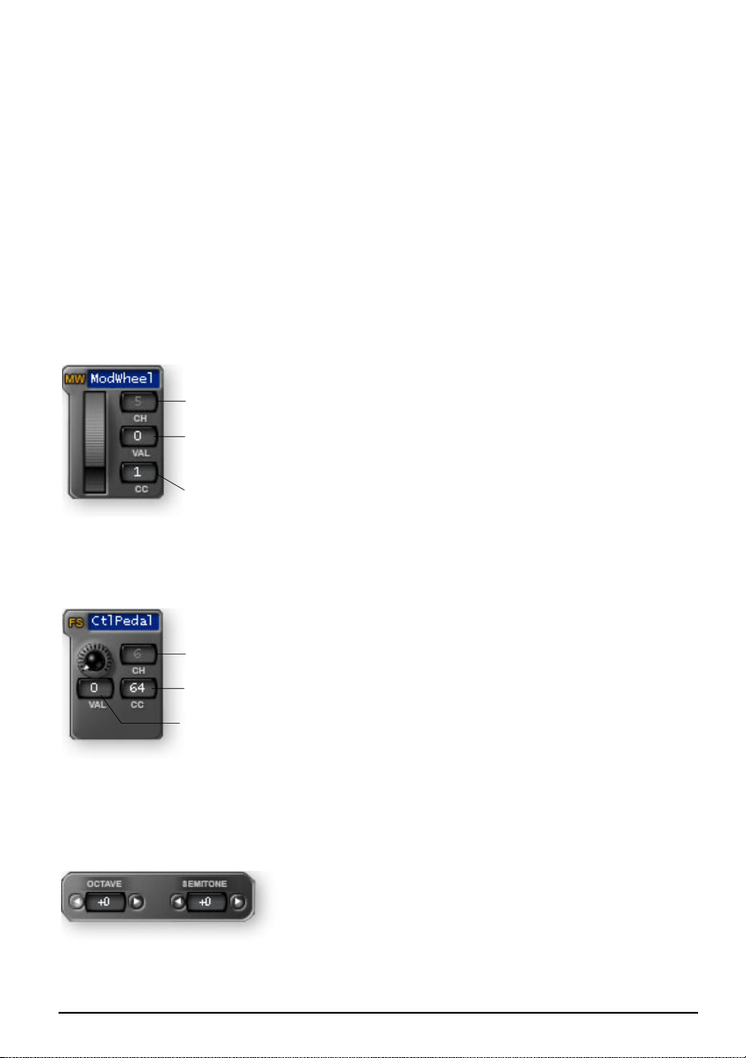
Mod Wheel Settings
The modulation wheel settings are program-
MIDI Channel
Initial Wheel
Setting
mable just like the other controller knobs with
an initial setting, CC number and MIDI channel.
The MIDI Channel field allows you to set the
MIDI channel for the mod wheel. This field is
unavailable unless the “MIDI Channel Number
CC Channel No.
Per Control” option is selected. (See page 35.)
You will normally leave the Mod Wheel set to it’s
default setting of CC 1, since this is a standard function on every MIDI synthesizer.
Pedal/Footswitch Settings
The Control Pedal input accepts either a
momentary-on footswitch or a continuously
MIDI Channel
CC Channel No.
Initial
Pedal Setting
variable pedal. Like the other controllers, an
initial setting, CC number and MIDI channel can
be programmed. The MIDI Channel field allows
you to set the MIDI channel for the mod wheel.
This field is unavailable unless the “MIDI
Channel Number Per Control” option is
selected. (See page 35.) The default setting for the Control Pedal is CC 64, which is
the standard MIDI sustain pedal number.
Octave / Semitone Transpose Settings
These settings allow you to transpose the keyboard
up or down in octave or semitone steps. The octave
transpose range is ±4 octaves. The semitone transposition range is -64 to +63 semitones.
X Board 37

E-MU X Board Control
Note Latch Mode Settings
This section allows you to program the high and
low keys for latch mode, as described on page 25.
You can also turn latch mode on or off by pressing
the amber-colored button. Note that you cannot
set a low key number higher that the high key, or a
high key number lower than the low key.
Save Controller Values in Patch
When this parameter is set to On, the
position of the 16 knobs, Mod Wheel
and Footswitch/Footpedal settings will
be saved with the Patch.
If this parameter is Off, the existing continuous controller settings are retained.
Send Controller Values on Patch Recall
When this parameter is set to On, the stored settings of the 16 Controller Knobs,
the Mod Wheel and the Footswitch/Footpedal will be transmitted when the Patch is
selected. When set to Off the continuous controller settings will not be transmitted
when the patch is selected.
Note: Pressing the Snapshot button will immediately send the stored controller
values.
Velocity Curve Select
This function selects one of the eight velocity curves to customize the velocity
response of the keyboard. Select a synthesizer preset that has velocity programmed
(such as a piano), then choose a curve that gives you the best control.
Click on an image to select the desired velocity curve for the patch. See page 27 for
descriptions of the curves.
E-MU Systems 38

E-MU X Board Control
Program Change per MIDI Channel
Master Enable
In this example, five program changes will be transmitted.
The X Board has the ability to transmit a MIDI Program Change on each of the 16
MIDI channels whenever a patch is selected. This feature allows you to set up all
your MIDI instruments for a performance by simply selecting a patch on the X
Board. Program Bank MSB and LSB numbers are also transmitted. See “MIDI Bank
Select Commands” on page 52 for more information.
The Master Enable button turns Program Change transmit on or off for all 16 MIDI
channels. The enable buttons over each channel slot allow you to select which
channels will transmit program change messages when the patch is selected.
This feature is only accessible via the X Board Control software.
Patch Editor View
All patch parameters can be edited in this screen. Any changes you make are
immediately sent to the active buffer on the X Board, but will not be stored.
Changes will be stored in the X Board if you:
1. Press the Store button or…
2. Change the Current Patch from the Bank View.
If you have made changes to the Patch Editor controls and don’t want them saved,
select the Revert function from the File menu to revert to the X Board’s stored
settings for that patch.
X Board 39

E-MU X Board Control
MENU ITEMS
E-MU X Board Menu
About E-MU X Board
This popup dialog box displays the current revision of the X Board Control
software.
Preferences…
Macintosh view
File View Folder
These options allow you to choose the location in your computer where saved
Banks and Patches will be stored.
Default Folder - Saved Patches and Banks will be stored in the selected folder.
Startup Folder - Default or Last - This option lets you choose whether the
Default bank or the last bank selected in “File, Choose
Folder…” will be shown when you launch the X Board
Control.
E-MU Systems 40

E-MU X Board Control
Backups
These options allow you to choose the location where automatic backups will be
stored and how many backup files will be retained 2-4. Backup files are created
whenever you quit the X Board Control application.
Backups Folder - Backup Patches and Banks will be stored in the selected
(Mac App only)
folder.
Num Backups Retained - Selects how many backup files will be retained
(2, 3 or 4).
Device
Auto Store Patches - Ask First or Always - When Ask First is selected, a popup
dialog box appears asking if you want to store when you
change a patch without storing. When Always is
selected, a modified patch is automatically stored
without asking when you change patches.
PC App -> shows “Auto save when changing patches”
Startup Device - Default or Last - This option selects which keyboard will
Note: On the PC this
is called:
“Program startup
folder for File View”.
be selected on startup when you have more than one X
Board connected to USB. You can choose the default X
Board (as selected in the Device menu), or you can
choose the last X Board you selected.
PC view
X Board 41

E-MU X Board Control
File Menu
Load From File (PC version)
This option allows you to Load saved Bank Files, Patch Files or Both into the X
Board Control.
Select Folder
Select File Type
To Load a Bank or Patch
1. Select Load from File from the File menu. The popup dialog box shown above
appears.
2. Locate the folder containing your Banks and P.atches. (The default folder is set
in the Preferences menu.)
3. Select Bank files, Patch files or Both to be shown.
4. Select the desired Bank or Patch file.
5. Press Open to load the file or Cancel to cancel the operation.
E-MU Systems 42

E-MU X Board Control
Save Patch (PC version)
This option allows you to Save X Board Patches to your hard disk.
To Save a Patch to Disk
1. Select Save Patch from the File menu. The popup dialog box shown below
appears.
2. Locate the folder where the Patch will be saved. (The default folder is set in the
Preferences menu.)
3. Select Patch files as the type.
4. Press Save to save the Patch or Cancel to cancel the operation.
To Save a Bank to Disk
1. Select Save Bank from the File menu. The popup dialog box shown above
appears.
2. Locate the folder where the Bank will be saved. (The default folder is set in the
Preferences menu.)
3. Select Bank files as the type.
4. Press Save to save the Bank or Cancel to cancel the operation.
X Board 43

E-MU X Board Control
Loading and Saving Files from the Mac
The Load and Save options in the File menu change depending on whether an
object in the File or Bank section is selected.
• Load/Save Bank - Select an object in the File Section.
• Load/Save Patch - Select an object in the Bank Section.
Load/Save Bank Load/Save Patch
File Section
Bank Section
Select an object in the File Section… Select an object in the Bank Section…
…then choose Load or Save from the File Menu.
E-MU Systems 44

E-MU X Board Control
Load From File (Mac version)
This option allows you to load saved Bank Files, Patch Files into the X Board
Control.
To Load a Bank or Patch
1. Select any object in the File Section to load a Bank.
Select any object in the Bank Section to load a Patch.
2. Select Load Bank or Patch from File in the File menu.
3. Locate the folder containing your Banks and Patches. (The default folder is set
in the Preferences menu.)
4. Select the desired Bank or Patch file. (Only the file type you selected will be
available to load.)
5. Press Open to load the file or Cancel to cancel the operation.
X Board 45

E-MU X Board Control
Save Bank or Patch (Mac version)
This option allows you to save X Board Banks or Patches to your hard disk.
To Save a Bank or Patch to Disk
1. Select any object in the File Section to save a Bank.
Select any object in the Bank Section to save a Patch.
2. Select Save Bank or Patch to File in the File menu.
3. Locate the folder containing your Banks and Patches. (The default folder is set
in the Preferences menu.)
4. Select the location for your Bank or Patch file.
5. Press Save to save the file or Cancel to cancel the operation.
Choose Folder
This option allows you to select the folder that will appear in the File View area of
the patch editor to be used for loading or saving X Board files.
Store
This menu option stores the current Patch into the X Board’s non-volatile memory.
This function duplicates the Store button on the X Board Control Patch Editor
screen.
E-MU Systems 46

E-MU X Board Control
Revert
The X Board Control automatically backs up the contents of the X Board whenever
you open the editor. This is so you can undo any changes you make during an
editing session if you so desire. See “Backups” on page 41.
Revert allows you to select one of the auto-backups so that you can “go back” to a
previous state of the X Board.
The Revert dialog box is shown below. The date and time of the auto-backups are
recorded. Backup number one is the oldest backup.The number of automatic
backups can be selected in the Preferences menu. See page 41.
• On the Macintosh version, a second “Patch” revert file is also created when you
open the application. This patch file is rewritten whenever the current patch s
edited. This allow you to revert to the last patch you edited.
X Board 47

E-MU X Board Control
Edit Menu
Cut
Selected patch files can be cut (removed) from the Bank View area. After choosing
Cut, the file is placed on a temporary “clipboard” so that it can be “Pasted” into
another patch location or into the selected File folder. (Select the new location,
then choose “Paste”.)
Cut can also be used to remove an edited patch. A default factory patch will be left
in its place.
Copy
This function copies a selected bank or patch from the patch or file area and places
it on a temporary “clipboard” so that it can be “Pasted” into another patch location
or into the selected File folder.
• Banks can be copied from the File View section or from the Bank Name in
the Bank Section.
• Patches can be copied from the File View section or from the list in the Bank
Section.
Paste
This function writes the clipboard contents into the file folder or into a patch
location.
• Banks can be pasted into the file folder or onto the Bank Name field in the
Bank View section.
• Patches can be pasted into the File View section or over an existing Patch in
the Bank Section.
Clear
This option removes the selected patch from the bank list. A default factory patch
will be left in its place.
Restore Pitch Wheel
The Pitch Wheel controller on the Patch Editor can be reprogrammed to operate as
a standard MIDI real-time controller. This option restores the Pitch Wheel
controller to its normal function as a synthesizer pitch wheel.
E-MU Systems 48

E-MU X Board Control
View Menu
Patch Editor
This option allows you to either show or hide the patch editor section of the X
Board Control software.
Sort Files
Files in the File View section can be sorted by Name, Type, or Date in either
ascending or descending order. The sort dialog box (Mac) is shown below. (This
option is only available in Mac OS X.)
Macintosh only
Refresh
Selecting this option updates the X Board Control display with the current state of
the X Board, including the active buffer and non-volatile memory contents. Refresh
also updates the File view with the current contents of the specified file folder
Refresh should be performed any time you have changed the Controls on the X
Board and want the X Board Control Editor to show these changes. For example, if
you adjust the controller knobs on the X Board, the display will not reflect the
current state of the knobs until you select Refresh.
X Board 49

E-MU X Board Control
Device Menu
Select
This option selects the current X Board in the event that you have more than one X
Board connected to your computer.
Help Menu
The Help menu calls the .pdf version of this operation manual.
E-MU Systems 50

Appendix
APPENDIX
MIDI Background
MIDI Channels & Continuous Controllers
MIDI continuous controllers may seem confusing at first, but they are really very
simple once you understand them. You probably already know that there are 16
MIDI channels per MIDI cable. Information on a MIDI channel will only be
received by an instrument set to receive that channel. MIDI channels are usually
associated with different sounds. In this way, up to 16 sounds per MIDI cable can
can be separately controlled.
Each MIDI channels uses three basic types of messages; note on/off, preset changes,
and continuous controller messages. When you play the keyboard, the X Board
transmits information about which notes were played and how hard.
The X Board can also send continuous controller information from its 16 knobs, pitch
and mod. wheels as well as aftertouch from the keyboard (key pressure applied after
the notes have been pressed). These controls are used to add more expression or
control.
The controller knobs send out information on separate continuous controller
numbers. There is a set of 128 continuous controller numbers (0-127) for each
MIDI channel. Some continuous controllers, such as modulation wheel, volume,
and pan have standardized numbers. For example, volume is usually sent on
continuous controller #7.
Normally, the X Board controller knobs and wheels transmit on a single MIDI
channel, but each of the 16 knobs and wheels can be programmed to transmit on a
different MIDI channel if you so desire. See page 35 for more information.
MIDI
Channel 1
Note
On/Off
Program
Change
Continuous
Controllers
MIDI
Channel 2
Note
On/Off
Program
Change
Continuous
Controllers
MIDI
Channel 3
Note
On/Off
Program
Change
Continuous
Controllers
MIDI
Channel 16
Note
On/Off
Program
Change
Continuous
Controllers
X Board 51

Appendix
g
MIDI Program Change Commands
The X Board has the ability to transmit a different MIDI Program Change command
on each of the 16 MIDI channels. This feature can only be programmed using the X
Board Control software.
MIDI Bank Select Commands
The X Board also transmits MIDI bank select commands using MIDI continuous
controller numbers. Continuous Controller (CC) 0 is the MSB (most significant
byte) and CC 32 is the LSB (least significant byte). Normally you send both the
MSB and LSB controllers to implement a bank change.
The selected bank remains selected until you change it (either via MIDI or by
changing the bank from the display). Standard MIDI Program Change commands
select from 128 presets within the selected bank.
Footpedal Wiring
The potentiometer value can be anywhere from 10KΩ to 250KΩ in value. Pedals
with these specifications are available at any music dealer.
Footpedal Wiring
Sleeve
10K - 250K
Ring
Tip
Sleeve
E-MU Systems 52
Tip
Rin

Appendix
LED Scrolling Text Messages
The three digit LED display doubles as a text display to help identify many of the
edit functions. You’ll notice that the scrolling messages mix upper and lower case
characters. This is a necessary compromise to display alphabetical characters on a
numeric display. The complete list of scrolling text messages are shown below.
Scrolling Text Messages
Displayed Text Translation
Select
Continuous Controller number
16 Channel CC number
Latch Low Note
Latch High Note
CC Store in Patch
CC Send on Patch Recall
Program Send on Patch Recall
Bank Select MSB
Bank Select LSB
Program Send Direct
Aftertouch
Local out destination (MIDI or USB)
MIDI Thru
USB Thru
MIDI Output Mode
Pedal Input Mode
SysEx Device ID
Panic Button
X Board 53

Appendix
MIDI Implementation Chart
MIDI Information Transmitted Recognized Remarks
MIDI Channels 1-16 No 16 MIDI Channels
Note Numbers 0-127 No
Program Change 0-127 No
Bank Select Response? Yes No MSB + LSB
Modes: Omni
Mono
Poly
Mode 4
Multi
Note On Velocity Yes No
Note Off Velocity No No
Channel Aftertouch Yes No
Poly (Key) Aftertouch No No
Pitch Bend Yes No
Active Sensing No No
System Reset No No
Tune Request No No
System Exclusive
Sample Dump Standard
File Dump
MIDI Tuning
Master Volume
Master Balance
Notation Information
Turn GM1 System On
Turn GM2 System On
Turn GM1 System Off
Other
NRPNs No No
RPN 00
RPN 01
RPN 02
RPN 03
RPN 04
RPN 05
MIDI Timing & Sync No No
MIDI Clock No No
Song Position Pointer No No
Song Select No No
Start
Continue
Stop
MIDI Time Code No No
MIDI Machine Control No No
MIDI Show Control No No
General MIDI Compat?
Is GM default mode?
DLS compatible?
Import DLS Files?
Export DLS Files?
(Mode 1)
(Mode 2)
(Mode 3)
(Y/N)
(Mode 5)
(See Remarks)
(Pitch Bend Sensi.)
(Chan. Fine Tune)
(Chan Coar. Tune)
(Tuning Prog Sel.)
(Tuning Bank Sel.)
(Mod Depth Rang)
No
No
No
No
No
No
No
No
No
Yes
No
No
No
No
No
No
No
No
No
No
No
No
No
No
No
No
No
No
No
No
No
No
No
No
No
No
No
No
No
No
No
No
No
No
No
No
No
No
No
No
No
No
No
No
No
No
No
No
No
No
E-MU Systems 54

Appendix
MIDI Implementation Chart (part 2 - Controllers)
Control # Function Transmitted Recognized Remarks
0 Bank Select MSB Yes No See Note *
1 Mod Wheel MSB Yes No *
2Breath Cntl MSB No No *
3No*
4 Foot Cntl MSB No No *
5 Portamento MSB No No *
6 Data Entry MSB No No *
7 Chan Volume MSB No No *
8 Balance MSB No No *
9 *
10 Pan MSB No No *
11 Expression MSB No No *
12 Effect Cntl 1 MSB No No *
13 Effect Cntl 2 MSB No No *
14 - 15 UNDEFINED - - - - - - *
16 GenPur Ctrl 1 MSB No No *
17 GenPur Ctrl 2 MSB No No *
18 GenPur Ctrl 3 MSB No No *
19 GenPur Ctrl 4 MSB No No *
20 - 31 UNDEFINED - - - - - - *
32 Bank Select LSB Yes No *
33 Mod Wheel LSB Yes No *
34 Breath Cntl LSB No No *
35 *
36 Foot Cntrlr LSB No No *
37 Portamento LSB No No *
38 Data Entry LSB No No *
39 Chan Volume LSB No No *
40 Balance LSB No No *
41 *
42 Pan LSB No No *
43 Expression LSB No No *
44 Effect Cntl 1 LSB No No *
45 Effect Cntl 2 LSB No No *
46 *
47 *
X Board 55

Appendix
MIDI Implementation Chart (part 2 - Controllers)
Control # Function Transmitted Recognized Remarks
48 Gen Pur Ctrl 1 LSB No No *
49 Gen Pur Ctrl 2 LSB No No *
50 Gen Pur Ctrl 3 LSB No No *
51 Gen Pur Ctrl 4 LSB No No *
52 *
53 *
54 *
55 *
56 *
57 *
58 *
59 *
60 *
61 *
62 *
63 *
64 Sustain Pedal Yes No *
65 Portamento on/off No No *
66 Sostenuto No No *
67 Soft Pedal No No *
68 Legato Footswitch No No *
69 Hold 2 No No *
70 Variation No No *
71 Timbre/Har Inten No No *
72 Release Time No No *
73 Attack Time No No *
74 Brightness No No *
75 Sound Cntrlr 6 No No *
76 Sound Cntrlr 7 No No *
77 Sound Cntrlr 8 No No *
78 Sound Cntrlr 9 No No *
79 Sound Cntrlr 10 No No *
80 Gen Purp Cntrlr 5 No No *
81 Gen Purp Cntrlr 6 No No *
82 Gen Pur Ctrlr 7 No No *
83 Gen Pur Ctrlr 8 No No *
84 Portamento Cntrl No No *
E-MU Systems 56

Appendix
MIDI Implementation Chart (part 2 - Controllers)
Control # Function Transmitted Recognized Remarks
85 - 90 Undefined - - - - - - *
91 Effects 1 Depth No No *
92 Effects 2 Depth No No *
93 Effects 3 Depth No No *
94 Effects 4 Depth No No *
95 Effects 5 Depth No No *
96 Data Increment No No
97 Data Decrement No No
98 NRPN (LSB) No No
99 NRPN (MSB) No No
100 RPN (LSB) No No
101 RPN (MSB) No No
102 - 119 UNDEFINED
120 All Sound Off Yes No
121 Reset All Controllers No No
122 Local Cntrl on/off No No
123 All Notes Off Yes No
124 Omni Mode Off No No
125 Omni Mode On No No
126 Poly Mode Off No No
127 Poly Mode On No No
NOTES: *
The X Board can transmit ANY continuous controller number from 1 to 127.
A “No” response simply indicates that the controller is not transmitted or
received by default.
X Board 57

Appendix
E-MU Systems 58

Numerics
INDEX
Numerics
16 Channel CC Number 27
16 Channel Control Mode 24
button 17
6 Volt DC Power Jack 19
A
Aftertouch On/Off 29
All Notes Off, sending MIDI 17
Auto Store Patches 41
B
Bank Send LSB 28
Bank Send MSB 28
Bank View, X Board Control software
33
Basic MIDI channel
select on Control software 35
select on X Board 22
Batteries, operating with 20
Battery Type 20
Browse Program Changes 29
Bypass Mode 26
Bypass, knob 18
C
CC Number
16 channel mode 27
definition 51
CC Send On Recall 28
Channel Select Button 17
Clear 48
Connection Diagrams 9
Continuous Controller 51
Controller
knobs 18
transmit as a “snapshot” 26
transmit when patch is selected 28
MIDI #7 51
Controller Settings, X Board Control 35
Copy 48
Cut 48
D
Data Slider 16
Data, entering 21
Default Folder 40
Device Field, X Board Control software
33
Driver Problems 12
E
Edit Button 16
E-MU USB MIDI Driver, not installed
12
Enter Button 16
External Program Change, sending 29
F
File View
folder 40
X Board Control software 32
Footpedal
jack 19
wiring diagram 52
Footswitch Type 19
Footswitch/Footpedal Input 19
X Board 59

H
H
Help Menu 50
Home Button 16
I
Implementation Chart, MIDI 54, 55
Initial Value, of knobs 35
Interface, using X Board as a MIDI 10,
19, 30
J
Jumping Knob Values 26
K
Keyboard USB, don’t use 9
Knob Bypass 26
button 17
Knobs
programming 24
setting initial value 35
L
Latch Mode 25
button 17
Load From File 42, 44, 45
Load, bank or patch 42, 45
Loops, triggering with the X Board 25
Lost Communication, between X Board
and audio app 12
M
Microsoft USB MIDI driver problem 12
MIDI
bank select commands 52
select bank 28
cc send on patch recall 28
channel select button 17
channel, changing 22
connection diagram 9
implementation chart 54, 55
interface, using X Board as 10, 19, 30
output jack 19
panic button 17
program change 29, 39, 52
per MIDI channel 39
transmit when patch is selected 28
program send on patch recall 28
Mixer, using controller knobs as a 24
N
Note Latch Mode Settings 38
O
Octave Transpose Buttons 17
On/Off Switch 19
P
Package Contents 8
Panic Button, MIDI 17
Paste 48
Patch Editor 34
show/hide 49
Patch Select Button 17
Patches
editing
from X Board 23
from X Board Control software 31
selecting 17, 21
storing 22
Pedal
setup 30
wiring diagram 52
PGM Browse Mode 29
PGM Send on Recall 28
Powering the X Board 20
Preferences Menu 40
Pressure, channel on/off 29
Problem Solving 12
E-MU Systems 60

R
Program Change Browsing 29
Program Change Commands 52
R
Red, patch name 33
Refresh 49
by re-selecting the device 33
Restore Pitch Wheel 36, 48
Revert 47
S
Save CC Value in Patch 28
Save Controller Values in Patch 38
Save, bank or patch 43, 46
Scrolling Text Messages 23, 53
Select, device 50
Semitone Transpose 27
Send Prog Change 29
Snap Shot Mode 26
Snapshot Button 18
Software Installation
Mac OS X 10
Windows 2000 10
Windows XP 11
Sort Files 49
Startup Device 41
Startup Folder 40
Store Button 16, 46
U
Uninstalling Drivers & App 11
Update Driver 13
USB Jack 19
USB Thru Mode 30
V
Velocity Curves
description 27
selecting 27
from X Board control app 38
View Menu 49
W
Windows Logo Testing Note 12
Wrong Driver Installed 12
X
X Board Control software 31
T
Text Display, scrolling 23
Text Messages, listing 53
Touch Response, adjusting 27
Transpose
keyboard 22
octave 17
semitone 27
Troubleshooting 12
X Board 61
 Loading...