

Page 1

EMULATOR IV
OPERATION MANUAL
PROFESSIONAL DIGITAL SAMPLING SYSTEM
FI460 REV. D
Copyright E-mu Systems Inc.
1994
Page 2

Emulator IV
Professional Digital Sampling System
Operation Manual
© 1994 E-mu Systems, Inc.
All Rights Reserved
• FI460 Rev. D
IMPORTANT NOTICE:
IN ORDER TO OBTAIN WARRANTY SERVICE ON
YOUR EMULATOR IV UNIT, THE SERIAL
NUMBER STICKER MUST BE INTACT AND YOU
MUST HAVE A SALES RECEIPT OR OTHER
PROOF OF PURCHASE. IF THERE IS NO SERIAL
NUMBER STICKER ON THE E-IV, PLEASE
CONTACT E-MU SYSTEMS AT ONCE.
THIS PRODUCT IS COVERED UNDER ONE OR
MORE OF THE FOLLOWING U. S. PATENTS:
3,969,682; 3,986,423; 4,404,529; 4,506,579;
4,699,038; 4,987,600; 5,013,105; 5,072,645;
5,111,727 AND FOREIGN PATENTS AND/OR
PENDING PATENTS. E-IV IS A REGISTERED
TRADEMARK OF E-MU SYSTEMS, INC.
E-MU WORLD HEADQUARTERS
E-MU SYSTEMS, INC. U.S.A.
P.O. BOX 660015
SCOTTS VALLEY, CA USA
95067–0015
TELEPHONE: 408-438-1921
FAX: 408-438-8612
EUROPE, AFRICA, MIDDLE EAST
E-MU SYSTEMS, LTD.
SUITE 6, ADAM FERGUSON HOUSE
ESKMILLS INDUSTRIAL PARK
MUSSELBURGH, EAST LOTHIAN
SCOTLAND, EH21 7PQ
TELEPHONE: +44 (0) 131-653-6556
FAX: +44 (0) 131-665-0473
C-iContents
Page 3

WARNING:
READ THIS
FIRST
This symbol is intended
to alert the user to the
presence of important
operating and maintenance (servicing)
instructions in the
literature accompanying
the appliance.
IMPORTANT SAFETY INSTRUCTIONS
Use in countries other than the U.S.A. may require the use of a
different line cord or attachment plug, or both. To reduce the risk
of fire or electric shock, refer servicing to qualified service personnel. To reduce risk of fire or electric shock do not expose this
product to rain or moisture.
GROUNDING INSTRUCTIONS
This product must be grounded. If it should malfunction or
break down, grounding provides a path of least resistance for
electric current, reducing the risk of electric shock. This product is
equipped with a cord having an equipment-grounding conductor
and a grounding plug. The plug must be plugged into an appropriate outlet properly installed and grounded in accordance with all
local codes and ordinances.
DANGER
Improper connection of equipment grounding conductor can
result in the risk of electric shock. Check with a qualified electrician or service personnel if you are in doubt as to whether the
product is properly grounded. Do not modify the plug provided
with this product. If it will not fit the outlet, have a proper outlet
installed by a qualified technician.
CAUTION
If the 6300, E-IV is rack mounted, a standard 19 inch open
frame rack must be used.
USER-MAINTENANCE INSTRUCTIONS
1. The E-IV should be kept clean and dust free. Periodically wipe
the unit with a clean, lint free cloth. Do not use solvents or
cleaners.
2. There are no user lubrication or adjustment requirements.
3. Refer all other servicing to qualified service personnel.
This symbol is intended
to alert the user to the
presence of un-insulated
dangerous voltage
within the product's
enclosure that may be of
sufficient magnitude to
constitute a risk of
electric shock to persons.
INSTRUCTIONS PERTAINING TO A RISK OF FIRE, ELECTRIC SHOCK, OR INJURY TO PERSONS
WARNING; When using electric products, basic precautions
should always be followed, including the following:
1. Read all instructions before using the E-IV.
2. To reduce the risk of injury, close supervision is necessary
when the E-IV is used near children.
3. Do not use the E-IV near water — for example near a bathtub,
washbowl, kitchen sink, in a wet basement, on a wet bar, or
near or in a swimming pool.
C-ii E-mu Systems Emulator IV
Page 4

4. The E-IV should be situated so that its location or position
does not interfere with its proper ventilation.
5. The E-IV should be located away from heat sources such as
radiators, heat registers, fireplaces, stoves, or ovens.
6. The E-IV should only be connected to a power supply of the
type described in the operating instructions and as marked on
the product.
7. Care should be taken so that objects do not fall and liquids are
not spilled into the enclosure of the E-IV through openings.
8. This E-IV may be equipped with a polarized line plug (one
blade wider that the other). This is a safety feature. If you are
unable to insert this plug into the outlet, do not defeat the
safety purpose of the plug. Contact an electrician to replace
your obsolete outlet.
9. The power supply cord of the E-IV should be unplugged from
the outlet when left unused for a long period of time.
10. This product, in combination with an amplifier and headphones and speakers, may be capable of producing sound
levels that could cause permanent hearing loss. Do not operate
for a long period of time at a high volume level or at a level
that is uncomfortable. If you experience any hearing loss or
ringing in the ears, consult an audiologist.
11. The product should be serviced by qualified service personnel
when:
A. The power supply cord has been damaged; or
B. Objects have fallen, or liquid has been spilled into the
product; or
C. The product has been exposed to rain; or
D. The product has been dropped or the enclosure damaged; or
E. The E-IV does not operate normally or exhibits a marked
change in performance.
12. All servicing should be referred to qualified service personnel.
SAVE THESE INSTRUCTIONS
C-iiiContents
Page 5
RADIO and TELEVISION INTERFERENCE
The equipment described in this manual generates and uses
radio-frequency energy. If it is not installed and used properly-that is, in strict accordance with our instructions - it may cause
interference with radio and television reception.
This equipment has been tested and complies with the limits for
a Class B computing device in accordance with the specifications
in Subpart J of Part 15 of the FCC rules. These rules are designed to
provide reasonable protection against such interference in a
residential installation. However, there is no guarantee that the
interference will not occur in a particular installation, especially if
a “rabbit ear” TV antenna is used.
If the E-IV does cause interference to radio or television reception, you can try to correct the interference by using one or more
of the following measures:
• Turn the television or radio antenna until the interference stops.
• Move the E-IV to one side or the other of the television or radio.
• Move the E-IV farther away from the television or radio.
• Plug the E-IV into an outlet on a different circuit than the
television or radio.
• Consider installing a rooftop antenna with a coaxial lead-in
between the antenna and television set.
6
CAUTION: TO REDUCE THE RISK OF ELECTRIC SHOCK
NO USER-SERVICEABLE PARTS INSIDE
REFER SERVICING TO QUALIFIED PERSONNEL
C-iv E-mu Systems Emulator IV
CAUTION
RISK OF ELECTRIC SHOCK
DO NOT OPEN
DO NOT REMOVE COVER.
Page 6

Contents
1 General Instructions
Introduction 1-3
Main Controls 1-6
Connections 1-9
Connecting to an Unformatted Hard Disk 1-13
Connecting to a Formatted SCSI Device 1-14
Sampling Basics 1-15
Definitions 1-17
Instant Gratification 1-28
2 Disk Menu
Disk Browser 2-2
Disk Utilities 2-6
Mount Drives 2-7
Copy System 2-7
Format Disk 2-8
Install File System 2-9
Backup 2-9
Load Bank 2-11
Save Bank 2-12
View 2-12
Info… 2-13
Folder 2-14
Bank 2-18
Preset 2-23
Sample 2-26
C-vContents
Page 7

The Modules
3 Master
Memory Statistics 3-3
Utilities Menu 3-4
Assignable Keys 3-4
Channel Volume 3-5
Tones 3-6
Volume Recalibration 3-6
Test Access 3-7
About the E-IV 3-8
Bank Menu 3-9
Erase Bank 3-9
Name Bank 3-10
Auto Load Bank 3-10
Tune Menu 3-11
Output Menu 3-13
Headroom 3-13
Output Format 3-15
Output Clock Rate 3-16
AES Boost 3-17
Miscellaneous Menu 3-18
MIDI Globals 3-25
Basic Channel 3-26
Mode 3-27
MIDI Mix 3-29
Controllers 3-30
Preferences 3-32
C-vi E-mu Systems Emulator IV
Page 8

4 Sample Manage
Overview 4-3
Utilities 4-4
Erase Sample 4-4
Copy Sample 4-5
Sample Dump 4-5
Defragment Memory 4-7
Name Sample 4-8
Create Sample 4-9
Left/Right Channels 4-9
Source & Rate 4-10
ADC Gain 4-11
Threshold 4-12
Sample Length 4-12
Arm Sample 4-13
Force Sample 4-13
Monitor On/Off 4-13
Automatic Parameters 4-14
Place Sample 4-18
Export Sample 4-19
Get Info 4-20
5 Sample Edit
Background 5-3
Utilities 5-12
Cut Section 5-13
Copy Section 5-15
Paste Section 5-16
DC Filter 5-20
Sample Calculator 5-21
Sample Integrity 5-22
Loop Type 5-23
C-viiContents
Page 9

Tools 1 5-25
Loop 5-25
Truncation 5-28
Taper 5-29
Gain Change 5-31
Stereo <-> Mono 5-33
Swap Left <-> Right 5-33
Tools 2 5-34
Sample Rate Convert 5-34
Digital Tuning 5-35
Compressor 5-36
Parametric EQ 5-41
Reverse Section 5-43
Tools 3 5-44
Time Compression 5-45
Pitch Change 5-46
Transform Multiplication 5-47
Doppler 5-48
Exciter 5-51
Undo 5-52
6 Preset Manage
Name Preset 6-4
Erase Preset 6-5
Copy Preset 6-6
New Preset 6-7
Export Preset 6-8
Get Info… 6-9
C-viii E-mu Systems Emulator IV
Page 10

7 Preset Edit
Background 7-2
Programming Basics 7-14
Dynamic Filter 7-14
Preset Editor 7-21
Preset Edit - Global 7-24
Preset Edit - Links 7-25
Utilities 7-26
Links - Key Window 7-29
Links - Velocity Window 7-31
Preset Edit - Voices 7-33
Utilities 7-34
Sample Zone 7-37
Sample Velocity Ranges 7-39
Voices - Key Window 7-41
Voices - Velocity Window 7-46
Voices - Realtime Window 7-49
Preset Edit - Dynamic Processing 7-51
Utilities 7-54
Voice Tuning, Modifiers & Setup 7-62
Amplifier/Filter 7-70
LFO/Auxiliary Envelope 7-76
Cords 7-79
8 Appendix
SCSI 8-3
Emulator IV Menu Maps 8-7
Memory Upgrade 8-10
Specifications 8-14
Warranty 8-15
Index 8-17
C-ixContents
Page 11

C-x E-mu Systems Emulator IV
Page 12

General
Instructions
1
Introduction 1-3
Main Controls 1-6
Connections 1-9
Connecting an Unformatted Hard Disk 1-13
Connecting a Formatted SCSI Device 1-14
Sampling Basics 1-15
Definitions 1-17
Instant Gratification 1-28
Instructions
General
General Instructions 1-1
Page 13

General
Instructions
1-2 E-mu Systems Emulator IV
Page 14

Introduction
Congratulations on your purchase of the E-IV Digital
Sampling System! The various functions of the E-IV are
organized in this manual by their module. Screen displays
and step-by-step instructions are described for all aspects of
use and operation. Sidebars are used to highlight important
points or to give useful operational tips which might not be
readily apparent.
If you are totally unfamiliar with samplers and synthesizers in general, you may need more information than this
manual provides. We suggest that you read some of the
many books and magazines on the subject of music synthesis. This will help you to get the most out of this extremely
powerful instrument.
Important Upgrade information
The Emulator IV is a software-based device. The features
and functions of the E-IV will be periodically enhanced and
upgraded and the new software will be mailed to you on
floppy disk. Please take a moment now to read the E-mu
Systems warranty and to fill out and send in your warranty
registration card. We NEED your mailing address in order to
send you upgrades and manual revisions.
Instructions
General
The Emulator IV
The E-IV was designed to be the ultimate in professional
sampling instruments. Every feature of the E-IV expands the
state-of-the-art in sampling instrument design, from ease of
use to the impeccable audio specifications. For starters, the
E-IV contains an incredible 128 channels of polyphony (64
stereo). The basic E-IV comes with 8 Megabytes of sample
memory, but this is user-expandable up to 128 megabytes
with standard SIMM modules. With fully expanded memory,
the E-IV provides over 24 minutes of sampling time!
General Instructions 1-3
Page 15

Sound Libraries
The E-IV has full access to the huge library of sounds
available from E-mu and other sources. It is fully compatible
with the legendary EIII and EIIIX libraries, and can transparently read Emax II and Akai S1000/S1100 banks as if they
were its own.
General
Instructions
Sound Storage
The E-IV can access up to 1000 samples per bank arranged
in up to 1000 presets. The dual connector 50-pin SCSI
interface provides access to high density media such as hard
disks, magneto-optical disks or CD-ROM. The integral 3.5"
floppy disk drive provides a convenient means of updating
the E-IV software which is periodically being enhanced and
improved. Most software upgrades will be mailed free to
registered owners. The E-IV also has 3 rear panel option slots
to accommodate hardware expansion cards.
Other professional features include selectable sample rates
of 22.05 kHz, 24 kHz, 44.1 kHz, and 48 kHz. D/A converters
are 18-bit linear. The Sigma-Delta A/D converters are 16-bit
linear. Sampling can be performed in either mono or true
stereo.
Advanced DSP
The E-IV’s advanced features make sampling a breeze.
Samples can be automatically truncated, normalized and
placed on the keyboard as the sample is taken and advanced
tools such as Auto Correlation, Loop Compression and
Crossfade Looping allow even the most difficult sounds to
be easily looped.
Samples can be digitally spliced and mixed with other
samples, and dynamically controlled from the keyboard
using velocity and positional crossfading and switching
functions. Advanced digital processing features such as
Sample Rate Conversion, Compression, Parametric Equalizer
and Digital Tuning allow you to shape raw samples more
quickly and with greater precision than computer based
systems. Samples can easilybe transferred between the E-IV
and an external computer via SCSI if so desired.
Additional digital processing functions include: Time
Compression and Expansion, which shorten or lengthen the
time of samples without changing the pitch; Transform
Multiplication, which can be used to create weird and
wonderful new timbres; and Doppler which allows you to
1-4 E-mu Systems Emulator IV
Page 16

move samples forward and backwards in space as well as
from side to side.
Digital Hardware Features
The E-IV’s digital hardware implements 128 Z-Plane
filters. These digital filters are very “analog-sounding” and
currently implement the following types of filters:
• 12, 24, or 36 dB/octave Lowpass filters with resonance
• 2nd & 4th order Highpass filters with resonance
• 2nd & 4th order Bandpass filters with resonance
• Three types of swept EQ filters
• Three phasers and one flanger with resonance
• Two morphing vocal formant filters
Modulation sources include three multi-stage envelope
generators and two multi-wave LFOs per channel, as well as
a full MIDI modulation control over virtually every parameter.
The E-IV is 16 part multi-timbral (32 MIDI channels with
option card), allowing complex sequencing and sound
effects creation, and can be controlled by remote control
using an external computer.
• Eight balanced polyphonic audio outputs allow you to
mix and process specific sounds. The main stereo outputs
are simultaneously available at 1/4" phone jacks and XLR
connectors.
• Resampling - The E-IV can resample its own output in the
digital domain for layering and the creation of new and
exciting effects.
• IBM compatible ASCII keyboard interface controls all E-IV
operations including naming and browsing.
• A digital interface (AES/EBU & S/PDIF) is another
standard option which facilitates the transfer of stereo
digital audio between digital recorders, mixers, etc.
The E-IV is based on the latest G-chip and H-chip digital
hardware. The G-chip allows smooth sample transposition
over a 10-octave range while the H-chips retain the warm,
musical character of traditional analog filters.
The E-IV is an extremely powerful and reliable seventh
generation instrument. We at E-mu Systems sincerely hope
it will help you realize and further your musical potential.
Instructions
General
General Instructions 1-5
Page 17
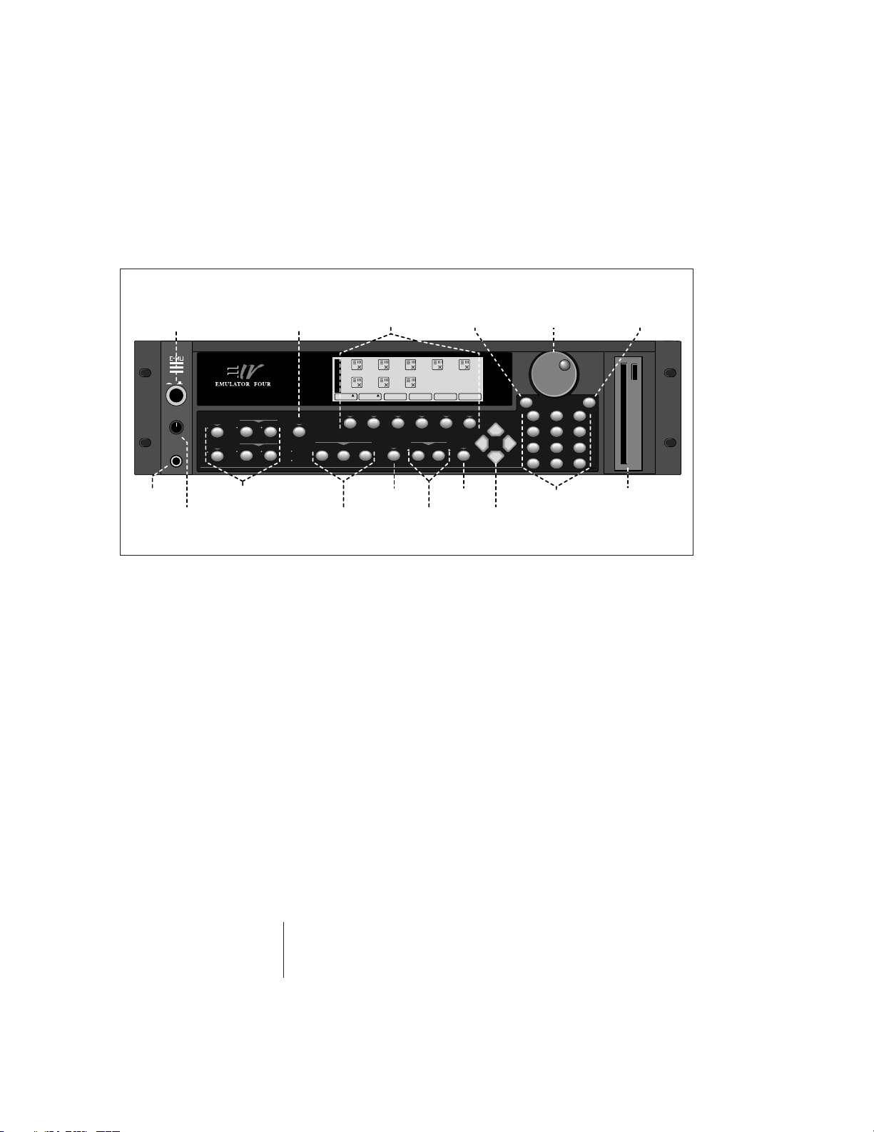
Main Controls
General
Power
Instructions
Switch
I
O
VOLUME
PHONES
MASTER
PRESET
MANAGE EDIT
SAMPLE
DISK
MANAGE EDIT
Audition
AUDITION
MIDI
SCSI
Function Keys
B
A
B00 Horns
B01 Proteus 1 B02 Synth Box
N
K
B05 Set 1 B06 World B07 Pianos
Utils Browse
F1 F2 F3 F4 F5
ASSIGNABLE KEYS
123
Decrement
B03 Indian B04 All Drums
Save…View Info…
Load
F6
PAGE
EXIT
PREV NEXT
ENTER
Control
DEC INC
ABC DEF
1
23
456
789
QZ
+/- 0 .
Increment
MNOJKLGHI
WXYTUVPRS
Data Entry
Phones
Master
Volume
Module
Select
Assignable
Keys
Page
Select
EnterExit
Cursor
Numeric
Keypad
Keys
Disk
Drive
Volume Control
This is the master volume control for all outputs including
digital I/O and the headphone output. The master volume is
a digital control. For maximum dynamic range, set this
control near or at maximum.
Module Select Keys
The functions of the Emulator IV are grouped according to
their function in six modules. The Sample Manage and
Sample Edit modules deal with operations at the sample
level. The Preset Manage and Preset Edit modules deal with
operations at the preset level. The Master module contains
functions that affect the entire machine. Any function that
has to do with the disk, such as loading, saving and the like
is accessed through the Disk module.
MIDI & SCSI Indicator LEDs
The LEDs illuminate to show activity on the SCSI bus or
incoming MIDI data.
1-6 E-mu Systems Emulator IV
Page 18

Exit Button
The exit button allows you to back out of a module one
menu at a time, each time the button is pressed. It can also
be used anytime you do not want to execute a particular
function. In the Sample Manage module, it can also be used
to terminate the sampling process.
Function Keys
The lower line of the display will usually contain a row of up
to six “soft key” buttons. These soft-key buttons indicate the
function of the function keys directly below them.
Assignable Keys
These are user-assigned keys which can cause a jump to any
screen.
Audition Button
The audition button allows you to play notes on the E-IV
directly from the front panel without having a MIDI keyboard connected. The note that will be played is selected
under “Tune” in the Master module. The Audition button
also allows you to play samples directly from the hard disk
before loading them when in the sample browser.
Page Select Keys
The previous and next page keys are primarily used to move
back and forth between pages when multiple pages of
options exist. Each button has an associated LED arrow
which illuminates if there is more information on the
previous or next page. Arrows in the top corners of the
display also indicate if there are more available pages. In the
preset selection screen, the page select keys can be used to
select the previous or next preset.
Instructions
General
Enter Button
The enter button is used to confirm a particular operation.
Enter can be used in place of an affirmative function key
response such as “OK” or “Go”. In the Disk Browser, pressing
the Enter key will advance the selection from: Drives ->
Folders -> Banks -> Presets -> Samples. (The Exit key reverses
the progression.)
General Instructions 1-7
Page 19

General
Instructions
- Tip: Holding down
the Enter key while
turning the data entry
control allows “fine
tuning” of the value by
one number per click.
Cursor Keys
The left, right, up, and down cursor keys are primarily used
to move the cursor around in the display. The cursor is a
reversed-out section in the display which indicates the
currently selected parameter. In the preset selection screen
the left and right cursor keys can be used to select the
previous or next preset.
Data Entry Control
The data entry control is a stepped, variable control which is
used to change parameter values. The control increments or
decrements the current value one unit each click. This
control incorporates acceleration (values advance faster if
the control is quickly turned).
Inc/Dec Keys
The increment and decrement keys are used primarily to
duplicate the function of the data entry control when a finer
degree of control is required. In the preset selection screen
the inc/dec keys can be used to select the previous or next
preset.
Numeric Key Pad
The numeric keypad is used to enter data in precise
amounts. For example, if you wanted to select preset 10,
enter 010 on the keypad and the preset will be instantly
selected. The numeric keypad can be used anytime the data
to be entered is a number. The numeric keypad can be used
to select samples and presets when you know the exact
number. You could simply enter the number without the
leading zero as in “10”, In this case, after entering the
number, you will be asked to confirm the value by pressing
“Go”. The +/- key can be used to indicate if the value is
positive or negative. The keypad can also be used for naming
as each key is labeled “telephone-style” with 3 characters
above the key.
Floppy Disk Drive
The floppy disk drive is used primarily to update the software of the E-IV, but can also be used to store and transfer
sound banks in a pinch. Due to the low capacity of floppy
disks, they are not practical for backing up sound data.
1-8 E-mu Systems Emulator IV
Page 20
Connections
Instructions
General
Expansion
Ports
SCSI SCSI
Sample
Inputs
Submix
Outputs
Jacks
MIDI
Interface
SCSI
SCSI is a high-speed parallel interface which is normally used
to interface the E-IV with external mass storage devices such
as hard disks or magneto-optical discs. The dual 50-pin SCSI
ports can also be used to link the E-IV with an external
computer for extremely fast file transfers. The E-IV contains
advanced SCSI links to facilitate multiple “master” devices
on the SCSI bus, such as multiple E-IVs or a computer and
an E-IV.
For more information on SCSI installation, see page 1-13.
Also refer to the manual that accompanies your external
SCSI device.
Main
Outputs
Digital
AC
Power
ASCII
Keyboard
Interface
General Instructions 1-9
Page 21
General
Instructions
Sample Inputs
The two sample input jacks accept any level input from
microphone to line level. Input impedance is 4KΩ. The gain
of the sample input preamplifiers is controlled from the New
screen in the Sample Manage module. When in the Sample
Manage module the sample inputs can be monitored from
the main outputs.
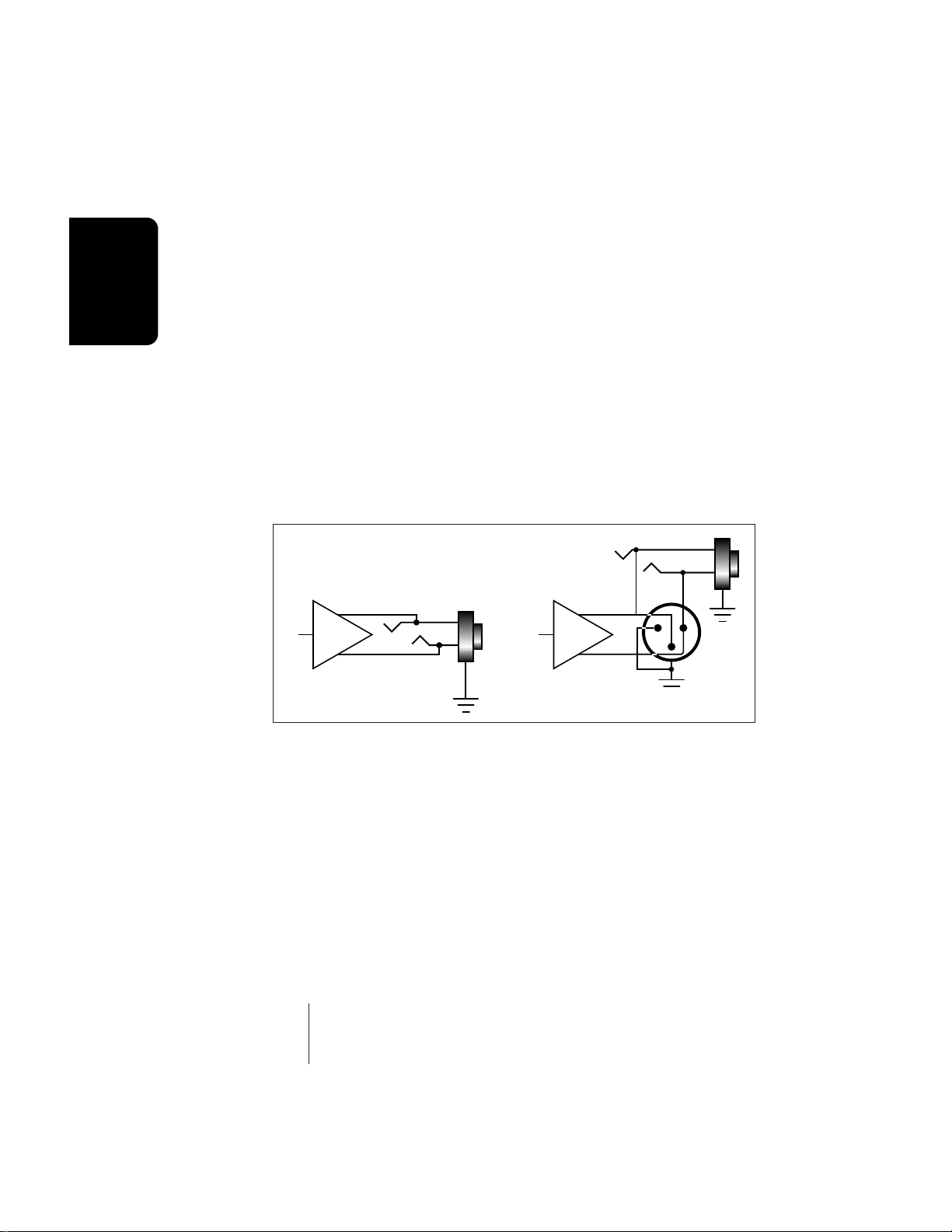
Main Outputs
The E-IV has provisions for a variety of output connection
schemes. The most common hookup will probably be using
the main stereo outputs. The main outputs are available at
both XLR and 1/4" phone jacks. Both outputs are balanced
outputs. Insert a stereo plug into the 1/4" output for a
balanced signal or a standard mono plug for unbalanced
signal. Output level is +4 dBm (approximately 1.23 volts
RMS). Output impedance is 50 ohms.
Tip
Submix
+
Balanced
Tip
-
Ring
Main
Balanced
Ring
+
12
3
-
Submix Outputs
In addition to the main stereo outputs, the E-IV has three
additional pairs of balanced submix outputs which can be
used when individual processing on specific instruments is
desired. Any combination of channels can be programmed
to appear at a submix output pair. Any voice can also be
assigned to a submix pair (In the Amplifier screen of the
Preset Edit module). MIDI channels can be assigned to the
submix pair using the Multimode Mix function in the
Master module. The Submix Outputs are balanced stereo
jacks with +4 dBm outputs on the tip and ring of the jack.
Output impedance is 50 ohms.
1-10 E-mu Systems Emulator IV
Page 22

MIDI Connection
E-IV provides a MIDI IN, a MIDI OUT and a MIDI THRU
port.
• The MIDI IN port connects to the MIDI OUT port of an
external MIDI controller which could be a keyboard, a
sequencer, MIDI drum kit or whatever. Note that the E-IV
can only respond to information that your controller
transmits. (i.e. If your MIDI keyboard does not have
velocity and pressure sensitivity, the E-IV will not respond
to velocity and pressure.)
• MIDI OUT can be connected to another MIDI instrument
or computer. The MIDI OUT jack is used to transmit
preset change information, or for MIDI sample dump
information (transfers sample data).
• MIDI THRU simply re-transmits any information received
at the MIDI IN port.
Digital I/O
The digital interface allows the E-IV to transfer digital audio
back and forth with other digital devices equipped with AES/
EBU or S/PDIF digital I/O. Keeping the signal in the digital
domain is desirable to keep the signal to noise level as high
as possible.
The digital input allows you to sample directly from a
DAT recorder or other digital device. The digital output
reflects the data at the stereo outputs of the E-IV. See the
Sample Manage module and Output Format (located under
Output in the Master menu) for more information.
Instructions
General
AC Power Connection
The E-IV may be used in either 110 volt or 220 volt environments at either 50 Hz or 60 Hz. No change of voltage settings is required. The E-IV automatically switches itself for
110 or 220 volt operation.
Expansion Ports
Three expansion ports allow for additional hardware upgrades such as an additional MIDI port (which adds another
16 MIDI channels) and other options to be announced.
General Instructions 1-11
Page 23

General
Instructions
ASCII Keyboard Interface
A standard IBM PC style ASCII keyboard can be connected
to the rear panel ASCII Keyboard connector. The keyboard
must be connected before power is applied in order for the
E-IV to recognize it. All the front panel controls of the E-IV
can be accessed via the keyboard. Having an ASCII keyboard
is also a real time saver when naming samples, presets and
banks. The keyboard functions are charted below.
E-IV ASCII KEYBOARD
Exit Esc
Ten Key Pad Ten Key Pad
Cursor Keys Cursor Keys, Ten Key Pad
Page Keys Ten Key Pad 3, 9
Numeric Selection [Num Lock, Ten Key Pad]
Inc/Dec +/-
F1-F6 [F1-F6]
Preset Edit [Alt, A], [Alt, F], [Ctrl, E]
Sample Manage [Alt, S]
Sample Edit [Alt, D], [Ctrl, G]
Preset Manage [Alt, P]
Master [Alt, M]
Multimode [Alt, Z]
Disk [Ctrl, D]
Load Bank [Ctrl, L], [Alt, ] ]
Save Bank [Ctrl, S], [Alt, [ ]
Search Dialog [Ctrl, F] in Browser
Rename Dialog [Ctrl, R] in Browser
Audition Preset/Sample [Ctrl, A] Depending on module
1-12 E-mu Systems Emulator IV
Page 24

þTo Connect the E-IV to an Unformatted Hard Disk
1. Position the SCSI device and the E-IV in a stable location. Hard disk drives are particularly susceptible to
shock and vibration. Make sure that you position your
hard disk where it won’t be bumped or moved while in
use.
2. Important: Make sure that all power to the E-IV and the
SCSI device is turned OFF.
3. Connect the SCSI device to your E-IV using a quality
SCSI cable. Make sure that the connectors are firmly
mated and that the wire “keepers” are locked in place.
There are two type of SCSI cables in common use: the
50-pin Centronics type and the 25-pin DB connector
type. The E-IV uses the 50-pin Centronics type connector.
4. Set the SCSI ID of your external SCSI device to any
number other than 6. (6 is the default ID of the E-IV).
Consult the operation manual of your SCSI device for
this procedure.
5. Turn on the external SCSI device and the E-IV.
6. Make sure your hard disk really is unformatted. Formatting a hard disk erases all the data on it. Press the Disk
button. If the display does not show the external hard
disk icon, the hard disk is may be unformatted. Try
mounting the drives (Utilities, in the Disk Browser). Also
check that the SCSI ID is not set to 6 (E-IV's default).
7. Format the hard disk. While in the Disk Browser, press
the soft key Utils. A new line of options will appear.
8. Select Format. The display will warn that formatting
erases everything on the hard disk. Press the soft key OK
to continue.
9. The E-IV will format the hard disk drive. Formatting
takes a few minutes. The time will vary depending of the
capacity of the disk..
10. After formatting, the hard disk will appear in the disk
browser and is now ready to accept data. Use the left/
right cursor keys or the data entry control to select the
newly formatted hard drive. Use the function key under
Info… to get information about the new drive.
Instructions
General
- Tip: If the hard disk
is already formatted
with another file system,
you can use the Install
File System function
instead of formatting
the disk . See Disk
Utilities.
General Instructions 1-13
Page 25

General
Instructions
- Tip: Use the “Mount
Drives” utility whenever
an external SCSI device
does not appear in the
display.
þTo Connect the E-IV to a Formatted SCSI Device
The E-IV will recognize and load from SCSI devices formatted for EIII, EIIIX, Emax II, ESI-32 and Akai S1000/S1100.
1. Position the SCSI device and the E-IV in a stable location.
2. Important: Make sure that all power to the E-IV and the
SCSI device is turned OFF before you connect or disconnect the SCSI cable.
3. Connect the SCSI device to your E-IV using a quality
SCSI cable. Make sure that the connectors are firmly
mated and that the wire “keepers” are locked in place.
The E-IV uses a 50-pin Centronics type connector.
4. Set the SCSI ID of your external SCSI device to any
number other than 6. (6 is the default ID of the E-IV,
although this number is user selectable. Master, Misc).
Consult the operation manual of your SCSI device for
this procedure.
5. Turn on the external SCSI device and the E-IV.
6. The SCSI device will appear as a new icon in the disk
browser screen.
1-14 E-mu Systems Emulator IV
Page 26
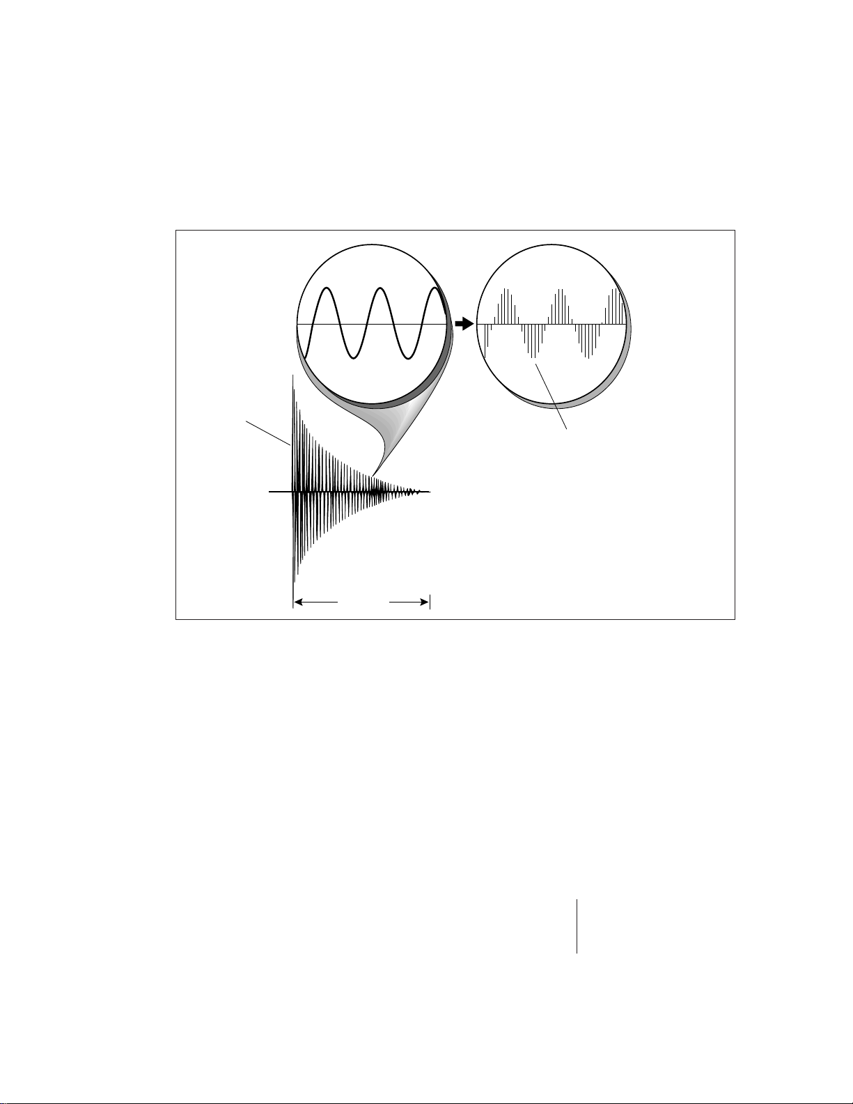
Sampling Basics
Percussive
Sample
Instructions
General
Each vertical line
represents a sample.
Each sample takes
a "snapshot" of the
instantaneous signal level.
1 second
Throughout this manual we will use the terms and concepts described and defined below. Read through this section
carefully, even if you don’t retain it all. You can refer back
periodically as you read through the manual until you
understand the basics and definitions.
The E-IV is conceptually like a tape recorder. However, the
recording process is very different since the E-IV digitally
records into its computer memory. Sounds for the E-IV can
be loaded via removable-media hard disk, magneto-optical
disk or CD-ROM using the SCSI interface; or they can be
sampled through the analog inputs or the AES/EBU digital
interface; or even through the MIDI interface using MIDI
Sample Dump.
General Instructions 1-15
Page 27

General
Instructions
Computers can accept information only in the form of
numbers, so the E-IV accepts audio signals coded into binary
numbers. Samplers work by examining (sampling) the
incoming signal level at a very high rate (44,100 times a
second for compact disc rate), and sequentially recording
these different levels in memory. Once stored, these samples
may be played back (in the proper sequence, of course) to
reconstruct the original signal. For instance, if a two-second
sound were being sampled at 44.1 kHz, it would require 2 X
44,100 or 88,200 samples to be recorded. As you might
imagine, shorter sounds require fewer samples.
A sound can be manipulated once it has been recorded.
Playing back the samples in reverse order from which they
were stored plays the sound backwards. Playing back the
samples at a faster rate than the rate at which they were
stored raises the pitch. Playing back at a slower rate lowers
the pitch, much like a tape recorder’s variable speed control.
Advanced onboard sample editing processors such as Time
Compression/Expansion and Doppler allow you to manipulate the sound in both time and space. Other digital processors provide standard studio functions such as parametric
equalization, compression and exciter. Far more radical
transformations are possible using our exclusive Transform
Multiplication process.
Sounds can also be manipulated in real-time by filtering
or by modulating amplitude and pitch.
1-16 E-mu Systems Emulator IV
Page 28

Definitions
How the E-IV Organizes Sounds
It is important to understand how the E-IV organizes
sounds in order to make best use of the instrument in the
shortest possible time. Many terms will be introduced now
that show up later in the manual.
You can think of the E-IV as resembling a collection of
sound-organizing modules, all contained within the E-IV
bank. Pathways indicate how information flows within the
E-IV. Let’s take a closer look at what makes up this information, and how it is transferred from one section of the
instrument to another. The Disk is the largest element in the
E-IV hierarchy; the Sample is the smallest element.
• Disk Drive - Floppy Disk, Hard Disks, CD-ROM Drives,
Optical Drives, etc.
• Folder - Used to group and organize collections of Banks.
• Bank - All samples voices and presets - Everything, that
resides in the E-IV's RAM (memory).
• Preset - One complete keyboard setup containing one or
more voices.
• Voice - One complete sound which contains one or more
samples with keyboard and velocity settings and all
programmable synthesizer parameters.
• Sample - An individual digital recording with a name,
sample rate and looping information.
Instructions
General
We’ll start with individual samples, then work our way
through the system.
General Instructions 1-17
Page 29

General
Instructions
The Sample
Loading in any sound in mono or stereo creates a sample,
the raw material with which the E-IV works. The total
available sampling time can be divided up any way you
like—one long sample, lots of short samples, a few medium
samples, or any combination thereof.
The term sample commonly means two different things:
1. A digital recording of a complete sound, or
2. Each snapshot of the sound that makes up the com-
plete sample. Confusing? You bet! In this manual, we’ll
assume sample means the complete recorded sound
unless indicated otherwise.
You can modify a raw sample in several ways:
• Transposition: A sample can be transposed up or down in
pitch to cover a particular range of the keyboard. By doing
this, it is not necessary to record a sample for every key.
• Sample Edit: In the E-IV, sample editing might consist of
Looping a sample (allowing even short samples to play
indefinitely), Truncating (cutting off unneeded parts of a
sample, thus saving memory), or any of a number of
digital processes that actually change the raw sample data.
Samples can also be named. It is usually a good idea to
name your samples with the original pitch as part of the
name so that you can place it on the keyboard later at the
proper pitch.
Voices
An Emulator IV voice is a complete sound which can be
assigned to a range of the keyboard. A sample is the soundgenerating portion of a voice. You can think of a voice as a
complete instrument consisting of one or more samples,
which can then be used as a building block in constructing
more complicated presets. A voice consists of one or more
samples, a low-pass filter with resonance, a dynamic amplifier, three, 6-stage envelope generators, two multi-wave LFOs
and 16 modulation routings called “Cords” to connect
everything together.
In a typical scenario, you might record several samples of
an instrument (such as a piano), then place them into the
same voice. Normally these samples would be placed side by
side on the keyboard as in the diagram on the following
page. You assign the sample to a range by setting the original
1-18 E-mu Systems Emulator IV
Page 30
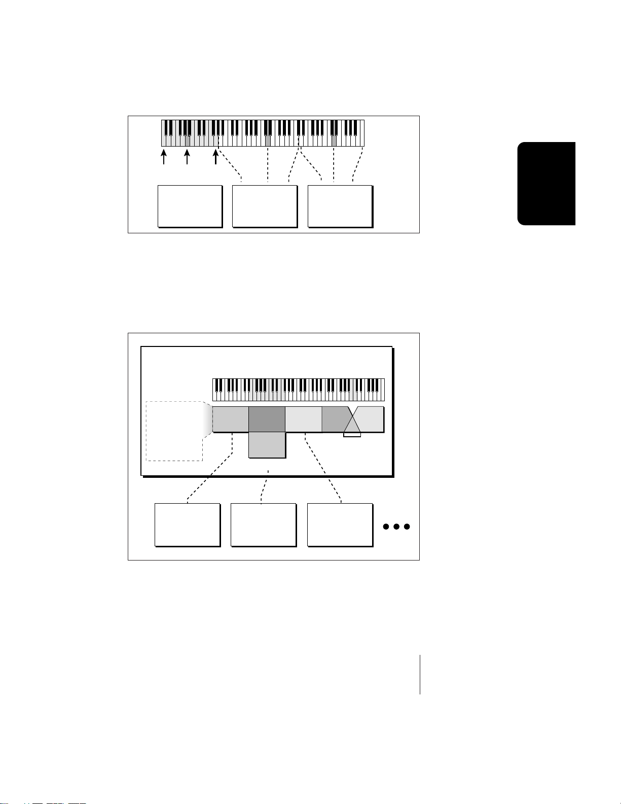
HighOrigLow HighOrigLow
Original
Low
Key
Key
High
Key
S02 Piano D3 S03 Piano D5S01 Piano A0
Sample Sample Sample
key, (which is usually the original pitch of the sample) a
high key and a low key. The number of samples needed for a
realistic emulation varies with the instrument, but in general, “More is better”.
When a sample is taken, it is automatically placed into a
voice with one sample. You can then place the voice (and its
sample) on the keyboard.
Voice
Each Sample:
Orig. Key
Tune
Volume
Pan
Key Range/Fades
Velo Range/Fades
S01
S10
S02
Velocity Crossfade
S03 S05
S04
Positional
Crossfade
Instructions
General
Sample 01
Loop, Info,
Sample Rate
Sample 02
Loop, Info,
Sample Rate
Sample 03
Loop, Info,
Sample Rate
If more than one voice is assigned to the same range, then
pressing a key in that range will play all the voices assigned
to that range. Voices assigned to the keyboard can be
crossfaded by their position on the keyboard or the key
velocity. Voices can also be switched or faded depending on
the value of a realtime controller such as a modulation
wheel, an LFO or an envelope generator.
General Instructions 1-19
Page 31

Preset
General
Instructions
KYBD Range KYBD Range KYBD Range
Voice
Voice
Voice
Group #
Key #
Velocity
Gate
Samples
Pitch
Chorus
Retrigger
LFOs
Glide
Start Offset
Envelope
Frequency
Gen.
Voice
Z-Plane
Filter
Resonance
Envelope
Gen.
Amp
Pan
Vol
- 16 Cords -
Envelope
Gen.
Velocity
or Realtime
Crossfade
L
R
Mod
Proc.
Sample 01
Loop, Info,
Sample Rate
Samples
S01
S10
S02
Velocity Crossfade
Sample 02
Loop, Info,
Sample Rate
1-20 E-mu Systems Emulator IV
S04
S03 S05
Positional
Crossfade
Sample 03
Loop, Info,
Sample Rate
Page 32

The Preset
A voice can be assigned to a single note on the keyboard,
or transposed polyphonically to cover a wider keyboard
range. A preset is one entire keyboard setup consisting of
one or more voices. The process of assigning, and optionally
transposing, samples to specific ranges of the keyboard is
called making a preset. Making a preset is a three-step
process:
1. Create the preset and give it a number and name.
2. Place voices to different keyboard ranges. For example,
with five voices you could assign each voice to cover one
octave of a five octave keyboard. A voice can be assigned
more than once within a given preset, and assigned to
more than one preset. Up to 256 voices can be assigned
to a single preset.
3. Choose from a number of available options that further
define the preset. Some examples are: assigning samples
to partially or fully overlap other samples, thus producing doubling effects, or assigning dynamic control to
individual voices in a preset. Overlapping voices can be
crossfaded using any modulation source. You can modify
voice parameters and set up MIDI and dynamic processing parameters.
The Emulator IV allows you to be very flexible in the way
you construct presets. Consider this — you can assign
samples to the keyboard inside the voice or assign single
sample voices to the keyboard. Unless you specify otherwise,
only one sample is assigned per voice. In this case you would
assign voices (and the single sample it contains) to the
keyboard and create presets. On the other hand, you may
wish to create finished voices before you start designing
presets and treat the voice as your finished sound. In this
case, the preset can be used to crossfade, layer or switch
multiple complex voices.
Instructions
General
The Bank
The memory bank contains samples, voices and presets.
Everything that is loaded into the E-IV is part of the bank.
Although the memory is volatile, meaning that the data
disappears when you turn off power, all bank data can be
saved permanently to the hard disk drive or other media to
keep a record of your work. An E-IV bank can hold up to
1000 presets (000-999).
General Instructions 1-21
Page 33

General
Instructions
BANK
00
100 Banks per Folder
BANK
BANK
01
BANK
Folders
A folder can contain up to 100 banks (0-99). You can use
folders to organize your sound banks or you might want to
include all the banks used for a particular project in a folder.
The number of folders in a disk depends on the size of the
disk. As an example, a one gigabyte hard disk can hold 96
folders.
The Internal Drive
A disk drive is a memory storage device that stores banks
of data. The E-IV has an optional internal hard disk drive
which can be used to load and store bank data. The floppy
BANK
02
03
BANK
98
99
drive on the E-IV is used mainly to update the operating
system software. (The operating system of a computer
consists of the instructions that tell the computer what to
do.) Because of the large bank size of the E-IV (8-128 MB) the
floppy disk is impractical for backing-up sound data, although it can be used to save sound banks if desired. However, other types of drives, as described below, can connect
to the E-IV to provide efficient sound storage.
• Floppy Disk Drive (Drive 0): The floppy disk drive
accommodates 3.5", double-sided, high-density (1.4MB)
floppy disks. The floppy drive is used mainly as a
convenient way to update the operating system software.
As new enhancements are developed, the new software is
distributed on floppy disks. This software can be copied
into Flash RAM and made a permanent part of the E-IV.
Undo: The E-IV
?
contains a handy Undo
feature which requires a
hard disk.
To Update the Software of the E-IV
1) Turn off power to the E-IV.
2) Insert the floppy disk into the drive with the label
side towards the center of the unit.
3) Turn on power.
4) Press Enter to update or Exit to cancel.
5) Wait for the E-IV to update its firmware.
• Hard Disk Drive (Drive 1): A hard disk provides the
advantages of much higher memory capacity and far
faster access time. However, the hard disk cannot be
removed and its data must be backed up to another
medium for safekeeping.
1-22 E-mu Systems Emulator IV
Page 34

External Drives
The E-IV contains two SCSI (Small Computer Systems
Interface) connectors on the rear panel. This interface is
commonly used in the computer industry, so many devices
made to work with computers—particularly mass storage
devices—will also work with the E-IV. Here are some of the
types of mass storage devices that can plug into the E-IV’s
SCSI connectors.
• Hard Disk Drive: A hard disk provides the advantages of
much higher memory capacity and far faster access time.
Transferring data to and from the E-IV is quite
straightforward. However, you cannot remove a hard disk
and replace it with another one—the disk is a permanent
part of the drive. There are three main cautions involved
with hard disks:
1. Hard disks are sensitive to extreme mechanical shocks. If
your hard disk falls off a keyboard stand, chances are the
hard disk will be damaged.
2. Make sure power is not interrupted when you write data
to the hard disk.
3. Hard disks have reached a very high level of reliability.
However, they can fail from time to time (as can any part
of a computer), so any data should be backed up periodically on some other medium.
Importing: When a
?
bank is imported from
another sampler, the E-IV
will organize the samples
into voices and
multisampled oscillators
as logically as possible.
For example, when
importing from the EIIIX,
samples with identical
dynamic processing
parameters will be placed
into the same voice.
Primary and secondary
layers will be placed in
groups 1 and 2.
Instructions
General
• Removable-media Hard Disk Drives: These are similar to
normal hard disk drives except that the disk itself can be
removed and replaced with another disk. Disk densities
can range from 44 Mbytes to well over 100 Mbytes per
platter. Removable-media hard disk drives allow you to
build a sound library of unlimited size and are quite
handy for transferring sounds between machines. They’re
also perfect for backups.
• CD-ROM Drive: A CD-ROM is a playback-only (data
cannot be written to it) mass storage memory device
whose capacity is approximately 660 Megabytes. Quality
CD-ROM libraries are available from several companies
(E-mu Systems, InVision, Northstar, Q-Up Arts). These can
be loaded into the bank as easily as you would load from a
hard disk.
General Instructions 1-23
Page 35

General
Instructions
• Magneto-Optical Drive: Basically a read/writable CD,
these high speed, high density storage devices are
currently the hottest thing around for storing large
amounts of sound data. Typically a magneto-optical drive
can hold upwards of 300 Mb per side and the removable
cartridges can be used over and over. Disk access time is
comparable to a normal hard disk.
Advantages: High-speed, high-density, reliable,
removable.
Disadvantage: Slower than most hard disks. High cost
(although prices are dropping fast).
Modules
A module controls a particular set of functions in the E-IV.
There are six main modules: Master, Disk, Preset Manage,
Preset Edit, Sample Manage and Sample Edit.
• Activating a Module: To work with a module, you must
first activate it. Press the button associated with the
desired module.
• Softkey Menus: Menus are selected using the soft keys
along the bottom of the display. Pop-up menus may also
be used when a field being edited has a small number of
choices.
• Page Selection: Each module contains several pages
which contain controls for additional functions.
In a graphical display, the different fields can be selected
in the following ways:
• By pressing the arrow keys (up, down, left, right)
• By turning the data entry control
• By assigning an assignable key to jump directly to the
screen you want to edit.
Pressing either the module button or the Exit button will
cancel any operation.
1-24 E-mu Systems Emulator IV
Page 36

The Module keys are located on the left side of the control panel. Each module affects a specific area of the Emulator IV's operation.
• Disk: This module controls everything to do with the disk
drives where the Emulator IV's sounds are stored. You can
browse through the disks, examine their contents and
audition sounds directly from a hard disk before loading.
If you are looking for a specific sound, the E-IV can help
you find it with its “Find” function.
• Master: This module contains functions that affect the
entire machine, such as master tuning offset, output
headroom, output sample rate, LCD contrast, and more.
• Sample Manage: This “recording studio” module records
sounds from the outside world into the bank. Features
include adjustable preamp gain, variable threshold
setting, and adjustable sample rate and length.
• Sample Edit: With this powerful module, you can edit a
sample's length, loop (i.e. infinitely sustain) any portion
of the sample and have the E-IV automatically find the
best loop points (Auto Correlate). You could splice two
different samples together, mix samples, or perform a
variety of advanced digital signal processes on the sample.
• Preset Manage: This module handles the preset
“housekeeping”, allowing you to create new presets, copy
them to any location, rename them or erase them.
• Preset Edit: This module lets you alter the synthesizer
voice parameters of the Emulator IV, such as shaping the
amplitude and filter dynamics or adjusting the keyboard
dynamic response. Voices can be placed on the keyboard,
moved around or shaped in just about any possible way.
Instructions
General
Saving
The bank only retains data for as long as the E-IV is
plugged in and turned on. Of course, we don’t expect you to
leave the thing on all the time, which brings us to the
subject of saving data.
Pressing the DISK button on the control panel shuttles all
the bank data (samples, voices and presets) to the drive of
your choice. A hard disk permanently stores data so that
even after turning off the E-IV, the disk will contain a record
of your work.
General Instructions 1-25
Page 37

General
Instructions
IF YOU DO NOT SAVE A BANK, ALL BANK DATA
WILL BE LOST WHEN YOU TURN OFF THE E-IV.
Do not wait until the end of a session to save. Save your
work periodically in case of power failure or some other
unforeseen circumstance that might erase the bank’s
memory. Hard disks are not infallible. All hard disk banks
should be backed up periodically to another hard disk or
other media. Should you improve the preset or sample later,
you can always replace the original with the revised version.
And if something goes wrong, the original will still be
available to save you the ordeal of starting from scratch.
Whenever you have done enough work that you would
hate to lose it, back it up!
Since the disk contains a record of the bank data, loading
the disk bank transfers all the sample and preset data into
the bank. This will replace the existing bank data, if any.
Default
A default setting is what we’ve judged to be a useful initial
setting, and remains in effect until you change it. For example, if you create a new preset, transpose will default to
“0”. Had it defaulted to +12, all new presets would be transposed up an octave.
D0 Floppy
This is the icon for the
floppy disk drive.
Icons
An icon is a little picture of an object such as a floppy
disk, a hard disk, folders, banks, presets or samples. In the
disk browser screens, icons are used as an easy way to identify and select the appropriate object. When an icon is
selected, the image will reverse (black to white & vice-versa).
The Cursor
The cursor is that small flashing line on the display. It sits
under the number or letter that will be altered if you enter
data. Entering a new value will overwrite the number or
letter above the cursor, whereupon the cursor will move on
to the next number or letter (if applicable). If the E-IV is
expecting a two or three-digit number, in most cases you
must enter all the required digits even if some of these are
zeroes. If it is expecting a single-digit number, entering 8
would be sufficient. In the preset selection screen, the E-IV
displays a soft key labeled “Go” after the first digit is entered.
Pressing this key confirms the entered value and instantly
1-26 E-mu Systems Emulator IV
Page 38

selects the preset. In other screens, you will be asked to
“Press OK to Confirm Change” after entering a value. Although the method of data entry may vary slightly in the
various modules, in all cases you will find that they are
logical and very easy to use.
Data Entry Control & Increment/Decrement Keys
In virtually all instances where the data entry control
selects options, the increment (Inc/Yes) and decrement (Dec/
No) switches duplicate the data entry control. Press Inc/Yes
to increase a value, or Dec/No to decrease by one value at a
time.
Selecting
When the instructions say to select an option, you can
use whatever method is most comfortable for you: the data
entry control, the increment/decrement keys, the numeric
keypad (if applicable) and, when naming, the keyboard keys.
Some functions do not implement all these options; you
can’t go wrong by trying, though. If a function doesn’t
respond to the numeric keypad, for instance, then pressing
the keypad will have no effect. Use the data entry control or
the inc/dec keys instead.
The Big Re-Cap
• A sample is a raw sound that is loaded into the bank.
• A voice is a complete Emulator IV sound, cosisting of one
or more samples, processed through the dynamic signal
processors, that is mapped onto the keyboard.
• To create a new preset, make sure you have all the samples
required for the preset, then assign combinations of voices
from the bank to specific sections of the keyboard.
• After arranging a bank, it can be saved to one or more
drives.
• Since loading from a hard disk fills the bank with samples,
voices and presets, you can group these voices and
samples into new presets, process the samples contained
in particular voices, or alter existing presets.
Instructions
General
General Instructions 1-27
Page 39

Instant Gratification
General
Instructions
This short section is designed to get you playing sounds in
the shortest amount of time. It contains only a partial
explanation of disk operations. For more complete instructions, see Chapter 2, Disk Module.
þLoading a Bank from the Hard Disk
1. From the main screen, press the Arrow function key (F6)
in the lower left corner of the display .
Press
Four additional soft key choices will appear.
3. Press the Load function key (F4). The following screen
will appear.
1-28 E-mu Systems Emulator IV
Page 40

4. Choose a bank to load using the data entry control, the
inc/dec keys or the numeric keypad. Press OK to load the
bank or Cancel to cancel the operation. If you pressed
“OK” the bank will be loaded and the first preset of the
bank you selected will appear.
þSelecting Presets
1. The main preset selection screen is shown above. Presets
can be selected using the data entry control, the cursor
keys, the page keys, the inc/dec keys, the numeric
keypad or from your MIDI controller. The previous and
next presets are displayed in the upper corners of the
display.
2. When using the numeric keypad to select presets, you
may enter leading zeros (i.e. type 0, 0 and 2 to select
preset 002) or simply type in 2, then press Go. If you do
not enter the leading zeros a screen will appear to confirm your choice. Press Go to confirm your choice or
Cancel to cancel the operation.
þSelecting Multimode
Multimode allows the Emulator IV to respond to multiple
MIDI channels at once. Press the Multi function key (F6) to
turn on Multimode and display the Multimode screen as the
main screen. The Multimode screen is shown below.
Instructions
General
The MIDI Mix screen allows you to display and adjust the
preset, volume, pan settings and output assignments for up
to 16 MIDI channels (32 channels with the optional MIDI
interface card). This is a useful feature to fine tune multitimbral sequences. This screen also allows you to override
the output channel programmed in the voice. Any volume
pan and preset changes made over MIDI will be reflected in
this display. (Volume = MIDI continuous controller channel
#7, Pan = MIDI continuous controller channel #10).
General Instructions 1-29
Page 41

General
Instructions
Note:MIDI channels
?
17-32 are not available
unless you have the
MIDI Interface Option
Card installed, which
adds 16 additional MIDI
channels.
Note: Pan ADDS to
?
the pan setting made in
the voice and is not an
absolute pan setting.
þTo Adjust the MIDI Mix
1. Select the desired MIDI channel using the up/down
cursor keys.
2. Select preset, volume, pan or the output assignments
using the left/right cursor keys. Change the parameter
values using the data entry control, the inc/dec keys, or
the numeric keypad.
3. Press the NEXT page key to select MIDI channels 17-32.
4. Press the key to call up the Load, Save and
Omni soft keys. Press Omni to return to normal mode.
5. Press the View key to change the display to list view
mode. The list view screen displays the values of the
pitch and modulation wheels. The amounts of the
wheels can also be adjusted here, just as if you were
moving the wheels on the controller.
- Tip: Omni mode
plays only the currently
selected preset from any
MIDI channel.
6. Press the right arrow key to display (or change) the
values of MIDI controllers A-H.
7. Press the View key to toggle the MIDI Mix back to
graphic display mode.
1-30 E-mu Systems Emulator IV
Page 42

Disk Menu
2
Disk Browser 2-2
Disk Utilities 2-6
Mount Drives 2-7
Copy System 2-7
Format Disk 2-8
Install File System 2-9
Backup 2-9
Load Bank 2-11
Save Bank 2-12
View 2-12
Disk
Info… 2-13
Folder 2-14
Bank 2-18
Preset 2-23
Sample 2-26
2-1Disk Menu
Page 43

Disk Browser
Icon
Disk
Identifier
D
I
S
K
Functions
Function
Keys
Utils Browse
- Tip: The Info… key
gives information about
the selected object..
The type of View (list or
icon) you choose is
remembered for each
level.
Selected Object
D0 Floppy
F1 F2
D1 Conner CPF10605
Load
F3
The Disk Browser makes it easy to navigate through the
different levels of the disk drives. Take the time to familiarize
yourself with this section because the browser is such an
integral part of the E-IV. A brief recap of the Emulator IV disk
hierarchy is as follows:
• Disk Drive - Floppy disk, hard disks, CD-ROM drives,
optical drives, etc.
• Folder - Used to group and organize collections of banks.
• Bank - A group of presets which can be loaded into the EIV's memory.
• Preset - A complete sound: samples, voices and all
programmable options.
F4 F5 F6
Save…View Info…
Activates
Sub
Menu
• Sample - An individual digital recording with looping
information.
2-2 E-mu Systems Emulator IV
Page 44

þTo Browse the Disk:
1. Press the Disk key. The LED will illuminate and the
screen shown on the previous page will appear. If you do
not have a hard disk connected, only the floppy disk will
appear in the display
2. Use the left/right cursor keys, the inc/dec keys or the
data entry knob to select the hard disk drive. The selected drive will be reversed out. In the diagram above,
the Conner hard disk is selected. When an object is
selected, its full name is displayed.
3. The browser lets you examine the various levels of the
disk, such as banks, presets and samples.
4. Press the View function key (F3). The display now
changes to a list format. Press the view key again to
return to the icon display.
5. Press the Info… function key (F6). a pop-up window
appears with information about the hard disk drive.
Press the OK function key to return.
Disk
6. Press the Browser function key (F2). Another row of
function key choices will appear.
D
D0 Floppy
I
D1 Conner CPF10605
S
K
Drives Folders
Man Browse
7. Press the function key under Banks. The LED will illuminate and the screen shown on the next page will appear.
Banks
Load
Presets Samples
Save… View Info…
2-3Disk Menu
Page 45

Disk
- Tip: Use the Exit key
to back out of the
pages.
- Tip: The Enter key
can be used to step
forward through the
Folder, Bank, Preset and
Sample browsers.
8. The display now shows the various banks of presets
resident on the hard disk. Use the cursor keys, inc/dec
keys, or the data entry knob to select the active object.
• If another page of choices exists, the right page arrow
LED will be illuminated.
9. Choose one of the banks, then press the function key
under Browser again, Press the function key under
Presets to examine the presets in the selected bank.
10. Choose one of the presets, then press the function key
under Browser again, Press the function key under
Samples to examine the samples in the selected preset.
2-4 E-mu Systems Emulator IV
Page 46

11. Pressing the Audition key while in the sample browser
plays the selected sample directly from disk.
12. Press the Info… function key (F6). a pop-up window
appears with information about the hard disk drive.
Press the OK function key to return.
S
S002 Piano A0 Type: E3 sample (stereo)
M
Length: 39139 samples Duration: 3.01 secs
P
Srate: 13000 Loop: 26319--39133
L
S005 Piano
S010 Piano
OK
13. Pressing the Exit key “backs you out” of the pages. Press
the exit key once from the sample browser to return to
the bank page. Pressing Exit again puts you in the folder
page. Press it once more and you're in the disk page.
Press Exit one more time and you're out of the disk
module altogether and back in the preset selection
screen.
EIIIEIII EIII EIII EIII
Disk
2-5Disk Menu
Page 47

D
I
D0 Floppy
S
K
Disk
Utils Browse
DISK
D1 Conner CPF10605
Load
The disk page of the browser contains functions and operations related to storage media such as floppy disks, hard
disks, CD-ROM drives, magneto-optical drives or whatever.
When in the disk page, all drives which are connected to the
SCSI port will appear as icons in the display.
DISK UTILITIES
The Disk Utilities menu contains several additional
functions. Pressing the Utils function key (F1) from the disk
browser enables a second row of soft keys.
Save…View Info…
• Mount Drives: Instructs the E-IV to check the SCSI bus
for the presence of SCSI devices.
• Copy System: Allows you to update and make copies of
the E-IV operating system supplied on floppy disk by
E-mu Systems or your authorized dealer.
• Format Disk: Initializes a floppy disk or a hard disk drive
to store Emulator IV data.
• Install FS: Allows you to install the E-IV file system on
pre-formatted hard disks.
• Backup: Hard disk drives can and do fail from time to
time. This function allows you to backup and restore
your valuable data to another hard disk or SCSI media.
• Find: This function allows you to find specific samples
presets, folders and banks anywhere in your library.
2-6 E-mu Systems Emulator IV
Page 48

Mount Drives
This utility instructs the E-IV to check the SCSI bus for the
presence of SCSI devices. Use this function whenever a
connected SCSI device does not appear in the disk browser.
þ To Mount Drives:
1. From the Disk Browser, press the Utilities function key
(F1).
2. Press the Mount function key (F1). The E-IV will mount
all SCSI devices.
Copy System
From time to time the E-IV operating system will be
updated with new features and functions. This software is
usually distributed on floppy disk and can be permanently
copied into the E-IV's Flash RAM so that it will automatically
load whenever you turn on the E-IV. Software can also be
saved to a floppy disk in order to back it up.
Each version of software is numbered and is indicated
when you select “About” under the “Utilities” menu in the
Master module. Copying software will not affect any other
data such as samples or presets.
þ To Update the E-IV Software:
1. Turn off power to the E-IV.
2. Insert the E-IV software floppy disk with the label side
toward the center of the E-IV.
3. Turn on power to the E-IV. The display will show the
software version on the floppy and ask if you wish to
update Flash RAM from the floppy software.
4. Press Enter to update, or Exit to cancel the operation.
Disk
þ To Backup the E-IV Software to Floppy Disk:
1. From the Disk Browser, select the floppy drive using the
data entry control, cursor keys or inc/dec keys.
2. Press the Utilities function key (F1).
3. Press the CopySys function key (F2). The display will ask
you to insert a floppy disk. Insert a formatted floppy disk
with the label side toward the center of the E-IV. (If the
floppy disk is unformatted, the E-IV will ask if you want
to format it.)
2-7Disk Menu
Page 49

Disk
4. Press Ye s, remove the current disk, insert a new disk and
press OK. Otherwise, press Cancel or Exit to cancel the
operation and return to the disk browser.
Format Disk
Before a new floppy disk or hard disk can record or store
any data, it must be told how to record this data. This is
called formatting. The floppy disk formatting procedure
should be run on any new disk, or on recycled disks previously used with other systems (such as personal computers)
since these will not be formatted correctly for the E-IV.
Formatting a hard disk or optical drive works exactly like
formatting a floppy disk. If the hard disk drive is not shown
in the disk browser, use the Mount Drive function. The hard
disk or optical drive should now be displayed.
þTo Format a Floppy Disk:
1. From the Disk Browser, select the floppy drive using the
data entry control, cursor keys or inc/dec keys.
2. Press the Utilities function key (F1).
3. Press the Format function key (F3). The display will ask
you to insert a floppy disk. Insert a floppy disk with the
label side toward the center of the E-IV.
4. Consider the implications of your action. Formatting a
floppy disk erases all information on that disk, com-
pletely. Press OK to format the disk or Cancel to cancel
the operation. Formatting takes about a minute and a
half.
5. After formatting the floppy disk, format another if
desired. The display will ask you if you want to format
another floppy. To do this, press Yes , remove the current
disk, insert a new disk and press OK. Otherwise, press
Cancel or Exit to cancel the operation and return to the
disk browser.
þTo Format a Hard Disk or Optical Disk:
1. From the Disk Browser, select the desired SCSI drive
using the data entry control, cursor keys or inc/dec keys.
2. Press the Utilities function key (F1).
3. Press the Format function key (F3). The display will
warn you if you are about to destroy Emulator IV data.
2-8 E-mu Systems Emulator IV
Page 50

4. Press OK to format the disk or Cancel to cancel the
operation. Formatting time varies depending on the size
of the disk.
Install File System
Many new hard disk and optical drives as well as removable
hard disk cartridges now come pre-formatted. This function
allows you to install the E-IV file system on pre-formatted
hard disks without having to reformat the disk. This can
save quite some time, especially with large capacity disks. To
find out if a disk is pre-formatted, try installing the file
system first. If this doesn't work, format the disk normally.
þ To Install the File System:
1. From the Disk Browser, select the desired SCSI drive
using the data entry control, cursor keys or inc/dec keys.
2. Press the Utilities function key (F1).
3. Press the Install FS function key (F4). The display will
warn you if you are about to destroy E-IV data.
4. Press OK to Install the file system on the disk or Cancel
to cancel the operation. Installing the file system time
takes a minute or more, depending on the size of the
disk.
Disk
Backup
This function allows you to backup and restore a portion or
the entire contents of the hard disk. You should develop the
habit of backing up any and all important data or risk
catastrophe at some future date. If you'd hate to lose it,
BACK IT UP!
þ To Backup your Hard Disk Data:
1. From the Disk Browser, select the SCSI drive you want to
back up using the cursor keys, inc/dec keys or the data
entry control.
2. Press the Utils function key (F1).
3. Press the Backup function key (F5). The display will
warn you if you are about to overwrite the current bank
in RAM.
4. Press OK to continue or Cancel to cancel the operation.
The following screen will appear.
Notes on Bank
?
Compatibility:
1) E-IV can load banks
from e-64, ESI-32, EIIIX,
EIII, Emax II, and Akai
hard disks or CD-ROMs.
2) E-IV cannot load
banks from ESI-32, EIIIX,
EIII, Emax II or Akai
floppies.
3) If E-IV backs up an
ESI-32/EIIIX bank, the
ESI-32/EIIIX will no
longer be able to load it.
2-9Disk Menu
Page 51

Disk
5. Select the destination drive using the inc/dec keys, or
data entry control.
6. Move the cursor down to “Backup Type” and select the
type of backup mode with the inc/dec keys or data entry
control.
Your choices are:
• All: Transfers all banks from the source disk to the
destination disk.
• Range: Transfers a selected range of banks from the source
disk to the destination disk.
• Incremental: Transfers only those banks which have been
modified since the last backup.
• Range: Transfers a selected range of banks from the source
disk to the destination disk.
- Tip: Use “Same as
Source” when backing up
to an ESI-32 or EIIIX drive
if you want these
machines to see your
E-IV files. They will
overwrite any files stored
in those locations. The
ESI-32 and EIIIX cannot
load E-IV files, but the
drive can be used for
both machines. Use “Use
Empty”␣ if backing up to
an ESI-32 or EIIIX drive
and you want the E-IV
files to be invisible to
those machines. In this
case, ESI or EIIIX files will
not be overwritten.
2-10 E-mu Systems Emulator IV
7. Move the cursor down to “Destination Bank Numbers”
to select where the banks will be placed on the destination disk.
Your choices are:
• Same as Source: Copies the banks into the same
numbered bank locations on the destination disk.
• Use Empty: Copies the banks into the lowest consecutive
empty bank locations on the destination disk.
8. When you have made your choices, press OK to continue or Cancel to cancel the operation.
Choosing All or Incremental causes the backup to begin
immediately. Choosing “Range”, causes the following screen
to appear.
Page 52

9. Select the Folder to be copied.
10. Select the starting and ending banks of the range to be
copied, then press Backup.
þ To Restore your Hard Disk Data:
Select your backup disk in the disk browser and simply
backup to your regular work disk.
LOAD BANK
A bank can be loaded directly from the disk browser.
þ To Load a Bank:
1. From the Disk Browser, press the Load function key (F4).
The following screen will appear:
D
L
Drive: D1 Conner CFP1060S
I
O
|Folder: F00 Folder
S
A
Bank: B01 Proteus 1/Pop X
K
D
Disk
Cancel
2. Choose a bank to load using the data entry control, the
inc/dec keys or the numeric keypad. You may also
change the current drive or folder by using the up/down
cursor keys to select the drive or folder. Press OK to load
the bank or Cancel to cancel the operation. If you
pressed “OK” the bank will be loaded and the main
preset selection screen will appear.
OK
2-11Disk Menu
Page 53

Disk
SAVE BANK
A bank can be saved to disk from the disk browser.
þTo Save a Bank:
1. From the Disk Browser, press the Save function key (F5).
The following screen will appear:
D
S
Drive: D1 Conner CFP1060S
I
A
|Folder: F00 Folder X
S
V
Bank: B01 Empty Bank
K
E
Cancel
2. Choose a location for the bank using the data entry
control, the inc/dec keys or the numeric keypad. You
may change the current drive or folder by using the up/
down cursor keys to select the drive or folder. Press OK to
load the bank or Cancel to cancel the operation. If you
pressed “OK” the bank will be saved and the main preset
selection screen will appear. If you are about to overwrite
an existing bank, the display will warn you.
OK
VIEW…
The display can be changed to a list format instead of the
normal icon-based format.
þTo Change the Display View:
From the Disk Browser, press the View function key (F3).
The screen will change to a list format. The List view is
shown below. Pressing the View function key again
toggles the view back to icon view.
2-12 E-mu Systems Emulator IV
Page 54

INFO…
The Emulator IV can display information on the
selected disk drive.
þ To Get Disk Info:
From the Disk Browser, press the Info… function
key (F6). A pop-up window will appear with the
vital statistics of the selected disk.
Disk
2-13Disk Menu
Page 55

F
F00 Main Folder F01 FX
L
D
R
FOLDER
Disk
Utils
Browse View Info…
Folders help you organize your banks of sounds by providing
another level between the bank and disk level. You may
want to organize your banks by a particular project or by the
type of sounds contained within, such as: Sound Effects,
Pianos, Strings, etc. If you do not wish to use folders, simply
place everything on the disk into one folder. You can skip
over the folder level in the browser and forget that folders
even exist.
FOLDER UTILITIES
The Folder Utilities menu contains several additional functions. Pressing the Utils function key (F1) from the folder
browser enables a second row of soft keys.
F
F00 Main Folder F01 FX
L
D
R
Man Browse View Info…
New
Find…RenameDelete
• New: Allows you to create a new folder.
• Delete: Allows you to delete an unwanted folder
• Rename: Allows you to rename the selected folder
• Find: Allows you to search the disk for a particular
folder.
2-14 E-mu Systems Emulator IV
Page 56

New
This utility allows you to create a new folder.
þ To Create a New Folder:
1. From the Folder Browser, press the Utilities function key
(F1).
2. Press the New function key (F2). A pop-up window will
appear prompting you to name your new folder.
3. Press OK after naming the new folder and it will appear
on the screen.
Delete
This utility allows you to delete a folder and all of its contents.
þ To Delete a Folder:
1. From the Folder Browser, select the folder you wish to
delete using the cursor keys, inc/dec keys or the data
entry control.
2. Press the Utilities function key (F1).
3. Press the Delete function key (F3). A pop-up window will
appear asking you if you want to delete the folder.
4. Press the OK function key (F6) to delete the folder and
its contents or the Cancel function key (F1) to cancel the
operation.
Disk
Rename
This utility allows you to rename a folder.
þ To Rename a Folder:
1. From the Folder Browser, select the folder you wish to
rename using the cursor keys, inc/dec keys or the data
entry control.
2. Press the Utilities function key (F1).
3. Press the Rename function key (F4). A pop-up window
will appear prompting you to rename the folder.
4. Change the name of the folder. Letters can be selected
using the numeric pad, data entry control, inc/dec keys
and cursor keys, or using an ASCII keyboard.
- Tip: The up/down
cursor keys add and
delete spaces when
renaming. The tab key
on an ASCII keyboard
clears the entire name.
2-15Disk Menu
Page 57

Disk
5. Press the OK function key (F6) to confirm the new name
or the Cancel function key (F1) to cancel the operation.
Find…
This utility searches for folders, banks, presets, or samples on
the disk for a particular search string (a pattern of letters and
numbers). If it finds the selected string anywhere in the name,
the item will be selected. Use the Find utility again to find
additional matching items.
þTo Find:
1. From the Folder Browser, press the Utils function key (F1).
2. Press the Find function key (F6). The screen shown below
will appear.
3. Select the type of item (folder, bank, preset or sample)
you wish to search for. If you have an idea of where the
item is located, you can narrow the search by inputting
additional data on the drive, folder or bank. Selecting
“All” tells the E-IV to search everything.
4. Press the String function key (F4), and enter the search
string. Letters can be selected using the numeric pad,
data entry control, inc/dec keys and cursor keys, or using
an ASCII keyboard.
5. Press the Search function key (F6) to search for the item
or the Cancel function key (F1) to cancel the operation.
2-16 E-mu Systems Emulator IV
Page 58

VIEW
The display can be changed to a list format instead of
the normal icon-based format.
þ To Change the Display View:
From the Folder Browser, press the View function
key (F3). The screen will change to a list format.
Pressing the View function key again toggles the
view back to icon view.
INFO…
The E-IV can display information on the selected
folder.
þ To Get Folder Info:
1. From the Folder Browser, press the Info… function key (F6). A popup window will appear with
the vital statistics of the selected disk.
Disk
F
F00 Main Folder F01 FX
L
D
R
F00 Main Folder
Max files: 112 Used: 16 14%
Total size of all files: 95.6mb
OK
2-17Disk Menu
Page 59

BANK
B
A
B00 Horns B02 Synth B03 Bosend B04 Orches
N
B01 Proteus 1/Pop
K
Disk
B06 Indian B07 Car Gl B09 APPLAU B50 Sines
Utils Browse
B08 SODA
Load
The Bank is a set of up to 1000 presets which can be loaded
into and saved to disk from the Emulator IV's internal
memory (RAM). When you save to disk, that collection of
presets and samples is a bank. Banks can be constructed as
large as the memory in your E-IV will allow, which in the
case of 128 MB, is large.
BANK UTILITIES
The Bank Utilities menu contains several additional functions. Pressing the Utils function key (F1) from the bank
browser enables a second row of soft keys.
Save…View Info…
• Delete: Allows you to delete an unwanted bank.
• Name: Allows you to name or rename the selected bank.
• Find: Allows you to search the disk for a particular bank.
2-18 E-mu Systems Emulator IV
Page 60

Delete
This utility allows you to delete an entire bank.
þ To Delete a Bank:
1. From the Bank Browser, select the bank you wish to
delete using the cursor keys, inc/dec keys or the data
entry control.
2. Press the Utilities function key (F1).
3. Press the Delete function key (F3). A pop-up window will
appear asking you if you want to delete the bank.
4. Press the OK function key (F6) to delete the bank or the
Cancel function key (F1) to cancel the operation.
Rename
This utility allows you to rename a bank.
þ To Rename a Bank:
1. From the Bank Browser, select the bank you wish to
rename using the cursor keys, inc/dec keys or the data
entry control.
2. Press the Utilities function key (F1).
3. Press the Rename function key (F4). A pop-up window
will appear prompting you to rename the bank.
4. Change the name of the bank. Letters can be selected
using the numeric pad data entry control, inc/dec keys
and cursor keys, or using an ASCII keyboard.
5. Press the OK function key (F6) to confirm the new name
or the Cancel function key (F1) to cancel the operation.
Disk
- Tip: The up/down
cursor keys add and
delete spaces when
renaming. The tab key
on an ASCII keyboard
clears the entire name.
2-19Disk Menu
Page 61

Disk
Find…
This utility searches your disk library for a particular pattern
of letters and numbers (a search string). If it finds the selected string anywhere in the name, the bank will be selected. Use the Find utility again to find additional matching
items.
þTo Find:
1. From the Bank Browser, press the Utilities function key
(F1).
2. Press the Find function key (F6). The screen shown
below will appear.
3. Select the type of item (folder, bank, preset or sample)
you wish to search for. If you have an idea of where the
item is located, you can narrow the search by inputting
additional data on the drive, folder or bank. Selecting
“All” tells the E-IV to search everything.
4. Press the String function key (F4), and enter the search
string. Letters can be selected using the numeric pad,
data entry control, inc/dec keys and cursor keys, or using
an ASCII keyboard.
5. Press the Search function key (F6) to search for the item
or the Cancel function key (F1) to cancel the operation.
LOAD BANK
A bank can be loaded from the bank browser.
þTo Load a Bank:
1. From the Bank Browser, select the bank you wish to load
using the cursor keys, inc/dec keys or the data entry
control.
2-20 E-mu Systems Emulator IV
Page 62

2. Press the Load function key (F4).
3. Loading a bank overwrites the bank currently in memory
unless you choose to Merge the banks.
4. Press Yes to overwrite the current bank or Cancel to
cancel the operation.
5. Press Merge to add the new bank to the current bank in
memory.
6. A pop-up dialog box will appear, prompting you to select
the starting destination preset. Use the data entry control, inc/dec keys or the numeric pad to select the starting destination preset. As the new bank is merged, its
presets will “fill in” any empty presets after this preset.
SAVE BANK
A bank can be saved to disk from the bank browser.
þ To Save a Bank:
1. From the Bank Browser, press the Save function key (F5).
The following screen will appear:
B
S
Drive: D1 Conner CFP1060S
A
A
|Folder: F00 Main Folder
N
V
Bank: B01 Empty Bank
E
K
Disk
Cancel
2. Choose a location for the bank using the data entry
control, the inc/dec keys or the numeric keypad. You
may change the current drive or folder by using the up/
down cursor keys to select the drive or folder. Press OK
to load the bank or Cancel to cancel the operation. If
you pressed “OK” the bank will be saved and the main
preset selection screen will appear. If you are about to
overwrite an existing bank, the display will warn you.
OK
2-21Disk Menu
Page 63

Disk
B08 SODA
Cancel Merge Yes
B
A
N
K
B00 Horns B02 Synth B03 Bosend B04 Orches
B06 Indian B07 Car Gl B09 APPLAU B50 Sines
B01 Proteus 1/Pop
?
Destroys resident bank…
continue?
VIEW
The display can be changed to a list format instead of the
normal icon-based format.
þTo Change the Display View:
From the Bank Browser, press the View function key
(F3). The screen will change to a list format. Pressing the
View function key again toggles the view back to icon
view.
INFO…
The E-IV can display information on the selected bank.
þTo Get Bank Info:
1. From the Bank Browser, press the Info… function key
(F6). A popup window will appear with the vital statistics
of the selected bank.
B
B01 Proteus 1/Pop X Type: E3X BANK
B00 Horns B02 Synth B03 Bosend B04 Orches
A
N
K
B06 Indian B07 Car Gl B09 APPLAU B50 Sines
B01 Proteus 1/Pop
Total bank size: 5.4MB
B08 SODA
OK
2. Press OK to return to the bank browser.
2-22 E-mu Systems Emulator IV
Page 64

PRESET
E3 E3 E3 E3
E3
P
Stereo Grand WarmGrand2 Bright Grand 128 V Piano
R
Warm Grand 1
S
T
Boys Choir Breathy Marcato Str Legato Str
Synth Lead
Utils Browse Load…View Info…
A preset is one complete keyboard setup containing voices
and samples arranged on the keyboard together will all
programmable synthesizer parameters.
UTILITIES
The Utilities menu contains several additional functions.
Pressing the Utils function key (F1) from the preset browser
enables a second row of soft keys. Only one option is currently implemented.
• Find: Allows you to search the disk for a particular bank.
E3E3E3E3E3
Disk
Find…
This utility searches your disk library for a particular pattern
of letters and numbers (a search string). If it finds the selected string anywhere in the name, the bank will be selected. Use the Find utility again to find additional matching
items.
þ To Find:
1. From the Preset Browser, press the Utilities function key
(F1).
2-23Disk Menu
Page 65

2. Press the Find function key (F6). The screen
shown below will appear.
Disk
3. Select the type of item (folder, bank, preset or sample)
you wish to search for. If you have an idea of where the
item is located, you can narrow the search by inputting
additional data on the drive, folder or bank. Selecting
“All” tells the E-IV to search everything.
4. Press the String function key (F4), and enter the search
string. Letters can be selected using the numeric pad,
data entry control, inc/dec keys and cursor keys, or using
an ASCII keyboard.
5. Press the Search function key (F6) to search for the item
or the Cancel function key (F1) to cancel the operation.
LOAD PRESET
An individual preset can be loaded into the bank from the
preset browser. This is a way you can create your own custom banks. Simply load in the desired presets, then save the
bank to disk.
þTo Load a Preset:
1. From the Bank Browser, select the bank containing the
preset you wish to load using the cursor keys, inc/dec
keys or the data entry control.
2. From the Preset Browser, select the preset you wish to
load.
2. Press the Load function key (F4). A pop-up window will
prompt you to select the destination preset.
2-24 E-mu Systems Emulator IV
Page 66

4. Choose a location for the preset using the data entry
control, the inc/dec keys or the numeric keypad. You
may overwrite an existing preset or choose an empty
preset as the destination.
5. Press OK to load the selected preset or Cancel to cancel
the operation.
VIEW
The display can be changed to a list format instead of the
normal icon-based format.
þ To Change the Display View:
From the Preset Browser, press the View function key
(F3). The screen will change to a list format. Pressing the
View function key again toggles the view back to icon
view.
INFO…
The E-IV can display information on the selected preset.
þ To Get Preset Info:
1. From the Preset Browser, press the Info… function key
(F6). A popup window will appear with the vital statistics
of the selected preset.
Disk
2. The preset size indicates the amount of memory that the
programmable preset parameters occupy. It does not
include the samples used in the preset. Press OK to
return to the preset browser.
2-25Disk Menu
Page 67

SAMPLE
EIII
EIII
EIII
EIII
EIII
S
M
P
Piano E0 Piano D1 Piano F#1 Piano C#2
EIII
Piano A0
EIII
EIII
EIII
EIII
L
Piano G#2 Piano C#3 PianoC#4 Piano F#4
Disk
Piano G#3
Utils Browse Load…View Info…
A sample is the most basic E-IV sound element and consists
of the digitized sound together with truncation and looping
parameters.
UTILITIES
The Utilities menu contains several additional functions.
Pressing the Utils function key (F1) from the sample browser
enables a second row of soft keys. Only one option is currently implemented.
• Find: Allows you to search the bank for a particular
sample.
Find…
This utility searches your disk library for a particular pattern
of letters and numbers (a search string). If it finds the selected string anywhere in the name, the bank will be selected. Use the Find utility again to find additional matching
items.
þTo Find:
1. From the Sample Browser, press the Utils function key
(F1).
2. Press the Find function key (F6). The find screen (shown
on the following page) screen will appear.
2-26 E-mu Systems Emulator IV
Page 68

3. Select the type of item (folder, bank, preset or sample)
you wish to search for. If you have an idea of where the
item is located, you can narrow the search by inputting
additional data on the drive, folder or bank. Selecting
“All” tells the E-IV to search everything.
4. Press the String function key (F4), and enter the search
string. Letters can be selected using the numeric pad,
data entry control, inc/dec keys and cursor keys, or using
an ASCII keyboard.
5. Press the Search function key (F6) to search for the item
or the Cancel function key (F1) to cancel the operation.
LOAD SAMPLE
An individual sample can be loaded into the bank from the
sample browser. This is an easy way to create your own
custom presets. Simply load in the desired samples, build
your preset, then save the bank to disk.
þ To Load a Sample:
1. From the Bank Browser, select the bank containing the
preset you wish to load using the cursor keys, inc/dec
keys or the data entry control.
2. From the Sample Browser, select the sample you wish to
load.
3. Press the Load function key (F4). A pop-up window will
prompt you to select the destination sample.
4. Choose a location for the sample using the data entry
control, the inc/dec keys or the numeric keypad. You
may overwrite an existing sample or choose an empty
sample as the destination.
5. Press OK to load the selected sample or Cancel to cancel
the operation.
Disk
2-27Disk Menu
Page 69

Disk
VIEW
The display can be changed to a list format instead of the
icon-based format.
þTo Change the Display View:
From the Sample Browser, press the View function key
(F3). The screen will change to a list format. Pressing the
View function key again toggles the view back to icon
view.
INFO…
The E-IV can display vital information on the selected
sample.
þTo Get Sample Info:
1. From the Sample Browser, press the Info… function key
(F6). A popup window will appear with information
about the selected preset.
S
EIIIEIII EIII EIII EIII
S002 Piano A0 Type: E3 sample (stereo)
M
Length: 39139 samples Duration: 3.01 secs
P
Srate: 13000 Loop: 26319--39133
L
2. The window indicates: sample length, duration in
seconds, the sample rate, and the loop points in samples.
Press OK to return to the sample browser.
S005 Piano
S010 Piano
OK
2-28 E-mu Systems Emulator IV
Page 70

Master Menu
3
Memory Statistics 3-3
Utilities Menu 3-4
Assignable Keys 3-4
Channel Volume 3-5
Tones 3-6
Volume Recalibration 3-6
Test Access 3-7
About the Emulator IV 3-8
Bank Menu 3-9
Erase Bank 3-9
Name Bank 3-10
Auto Load Bank 3-10
Tune Menu 3-11
Master
Output Menu 3-13
Headroom 3-13
Output Format 3-15
Output Clock Rate 3-16
AES Boost 3-17
Miscellaneous Menu 3-18
MIDI Globals 3-25
Basic Channel 3-26
Mode 3-27
MIDI Mix 3-29
Controllers 3-30
Preferences 3-32
3-1Master Menu
Page 71

Master
3-2 E-mu Systems Emulator IV
Page 72

Memory Statistics
The Master Menu contains functions which affect the
entire machine, not just certain presets, or banks such as
overall tuning, LCD contrast, MIDI modes etc.
The main screen shows the E-IV's memory status. There
are two types of memory in the Emulator IV, preset memory
and sample memory. An E-IV contains around half a megabyte of preset memory. The amount of sample memory can
vary from 8 megabytes to 128 megabytes. Preset memory is
used to hold the preset parameter information. Sample
memory contains the actual samples. Presets require much
less memory than samples, so you are not likely to ever run
out, even when creating huge banks.
The master menu contains six main sub menus:
• Utilities - Controls for the assignable keys, test tones and
volume control recalibration. Also contains the channel
status indicator, credits and software version display.
• Bank - Allows you to name or erase the bank and set a
bank to be auto-loaded on power-up.
• Tuning - Contains functions related to tuning.
• Output - Contains functions related to the audio outputs
and the digital audio interface.
• Miscellaneous - LCD contrast and SCSI utilities, etc.
Master
- Tip: The Master
settings are saved into
flash RAM when you exit
the module.
• MIDI - Contains global MIDI controls, velocity curve and
other miscellaneous MIDI functions.
3-3Master Menu
Page 73

Master
Utilities
The Master Utilities menu contains several additional
functions.
• Assignable Keys
• Channel Volume
• Reference Tones
• Recalibration
• Test Access
• About the E-IV
ASSIGNABLE KEYS
The three assignable keys on the front panel of E-IV can
be programmed to call up any almost any screen with a
single key press. This saves you from having to page through
multiple menus to find the screen you want to edit. The
assignable keys can be programmed either from the assignable keys screen or directly from any screen you are working
in.
þTo Program the Assignable Keys from the Master Menu
1. Press the Master key. The LED will illuminate and the
Memory Statistics screen will appear.
2. Press the Utilities function key (F1). A second row of soft
keys will appear.
3. Press the AsnKey function key (F1). The following screen
will appear.
3-4 E-mu Systems Emulator IV
Page 74

4. Use the data entry control or the inc/dec keys to change
the screen associated with each assignable key.
5. Press Save to store the assignable keys settings and
return to the memory statistics screen.
6. Press Cancel to cancel the operation and return to the
memory statistics screen.
þTo Program an Assignable Key from the Current Screen
This method allows you to program an assignable key to
the screen you are currently in.
1. Press and hold one of the assignable keys from any
screen in the Emulator IV.
2. After two seconds a pop up window will appear informing you that the assignable key has been programmed
for the current screen.
CHANNEL VOLUME
This function calls up a bar graph display showing the
volume of all 128 output channels of the E-IV. The channel
status display is a useful indicator of your channel usage.
The 128 channels of the E-IV are assigned in a circular order,
( i.e. 1, 2, 3… 128, then back to 1). Channels become available for reassignment when their output volume falls below
a certain level.
Master
3-5Master Menu
Page 75

Master
TONES
This function generates accurate reference tones which
can be used to troubleshoot your audio system without
loading a bank or to test each output of the E-IV.
þTo Enable the Reference Tone
1. Press the Master key. The LED will illuminate and the
Memory Statistics screen will appear.
2. Press the Utilities function key (F1). A second row of soft
keys will appear.
3. Press the Tones… function key (F3). The following
screen will appear.
4. Adjust the frequency, waveform, gain, and the output
submix channel using the data entry control or inc/dec
keys.
5. Press Exit to return to the memory statistics screen.
RECALIBRATION
This screen allows you to recalibrate the front panel
volume control on the E-IV. The analog components of the
volume control may change slightly over time. Use this
function if the front panel volume control does not seem to
be functioning properly.
þTo Recalibrate the Volume Control
1. Press the Master key. The LED will illuminate and the
Memory Statistics screen will appear.
2. Press the Utilities function key (F1). A second row of soft
keys will appear.
3. Press the Recal… function key (F4). The following screen
will appear.
3-6 E-mu Systems Emulator IV
Page 76

4. Follow the instructions and adjust the volume knob to
the minimum position, then press OK.
5. The display will ask you to move the control to the
maximum position. Do this and press OK.
6. The high and low values will be displayed. Press OK to
store the values in Flash RAM and return to the memory
statistics screen. Press Cancel or Exit to cancel the
operation and return to the memory statistics screen.
TEST ACCESS
This screen provides access to the Service Center diagnostic routines. Some of the diagnostic routines have the potential to destroy the data on your hard disk. It is for this reason
that the diagnostics are protected from casual use by a secret
password.
þTo Access the Diagnostic Access Screen
1. Press the Master key. The LED will illuminate and the
Memory Statistics screen will appear.
3. Press the Utilities function key (F1). A second row of soft
keys will appear.
5. Press the Tests function key (F5). A pop up dialog box
will appear asking for the diagnostics password.
8. Enter the proper password then press OK to enter the
diagnostics menus.
what? you don't know the secret
password? if we told you, it wouldn't be a secret.
Master
3-7Master Menu
Page 77

Master
ABOUT THE EMULATOR IV
This screen displays the current software version resident
in the E-IV. It also credits the creators of the E-IV and displays the phone number to order additional sounds.
þTo List the Software Version
1. Press the Master key. The LED will illuminate and the
Memory Statistics screen will appear.
2. Press the Utilities function key (F1). A second row of soft
keys will appear.
3. Press the About… function key (F6). A pop-up dialog
box lists the resident software version.
4. Press Exit to return to the memory statistics screen.
3-8 E-mu Systems Emulator IV
Page 78

Bank
The Bank submenu currently contains only two functions,
which allow you to name and erase the bank.
ERASE BANK
Erasing a bank erases ALL the memory in the Emulator IV
RAM which includes all samples, voices and presets. Erasing
the bank does not erase anything stored on your hard disk,
only the contents of the E-IV's RAM.
þTo Erase the Bank:
1. Press the Master key. The LED will illuminate and the
Memory Statistics screen will appear.
2. Press the Bank function key (F2). A second row of soft
keys will appear.
3. Press the Erase… function key (F1). A pop-up dialog box
will appear asking you if you want to erase all presets
and samples.
4. Press the OK to erase the bank or Cancel to cancel the
operation.
Master
3-9Master Menu
Page 79

Master
& Caution:
Bank Load works on
bank numbers, not their
names. If you move a
bank to another location
or switch removable
media, the bank may
not load or the wrong
bank may be loaded on
power-up.
Auto
NAME BANK
This utility allows you to name the current bank.
þTo Name the Bank:
1. Press the Master key. The LED will illuminate and the
Memory Statistics screen will appear.
2. Press the Bank function key (F2). A second row of soft
keys will appear.
3. Press the Name… function key (F2). A pop-up dialog box
will appear asking you to enter the new bank name.
4. Name the bank. Letters can be selected using the numeric keypad, data entry control, inc/dec keys and
cursor keys, or using an ASCII keyboard.
5. Press OK to clear the bank or Cancel to cancel the
operation.
AUTO BANK LOAD
This function automatically loads the selected bank
whenever the E-IV is first powered up.
þTo Set the Auto Load Bank:
1. Press the Master key. The LED will illuminate and the
Memory Statistics screen will appear.
2. Press the Bank function key (F2). A second row of soft
keys will appear.
3. Press the Auto… function key (F3). The pop-up dialog
box shown below will appear.
4. Set the bank to be automatically loaded on power up.
Banks can be selected using the numeric keypad, data
entry control, inc/dec keys and cursor keys.
5. Press Save to confirm your choice or Cancel to cancel
the operation.
3-10 E-mu Systems Emulator IV
Page 80

Tune
The tune submenu contains three additional functions.
TUNING OFFSET
Tuning Offset adjusts the overall tuning of the Emulator
IV so that it can be tuned to other instruments. The range of
tuning offset is ±100 cents or 1 semitone in approximately
1.2 cent increments.
þTo Change the Tuning Offset:
1. Press the Master key. The LED will illuminate and the
Memory Statistics screen will appear.
2. Press the Tune function key (F3). The following screen
will appear.
3. If it is not already there, move the cursor to the tuning
offset amount using the cursor keys or by pressing the F1
key.
4. Adjust the tuning offset of the E-IV using the data entry
control, or inc/dec keys.
5. Press the Exit key to return to the memory statistics
screen.
Master
3-11Master Menu
Page 81

& Caution:
transposition before
selecting or modifying
any presets to prevent
confusion. Transpose
transposes the key
number rather than the
sample assignment,
Selecting the zone and
any other use of the
keyboard will show the
transposed key number.
Turn off
Master
TRANSPOSE
This function transposes the Emulator IV in half-step
intervals. The range of transposition is ±1 octave. Transpose
allows you to play in a different key without having to use
different fingerings. Transpose will also allow you to play
beyond the range of your physical keyboard.
þTo Change the Transposition:
1. Press the Master key. The LED will illuminate and the
Memory Statistics screen will appear.
2. Press the Tune function key (F3). The following screen
will appear.
3. Move the cursor to the transposition amount using the
cursor keys or by pressing the F2 key.
4. Adjust the transposition of the E-IV using the data entry
control, or inc/dec keys.
5. Press the Exit key to return to the memory statistics
screen.
AUDITION KEY
This function allows you to set the key that will be played
when the audition key on the front panel is pressed (except
in the Sample Edit module where the audition key auditions
samples from disk). The audition key allows you to audition
sounds from the Emulator IV without having a MIDI keyboard connected.
þTo Change the Audition Key:
1. Press the Master key. The LED will illuminate and the
Memory Statistics screen will appear.
2. Press the Tune function key (F3). The following screen
will appear.
3. If it is not already there, move the cursor to the audition
key using the cursor keys or by pressing the F3 key.
4. Select the audition key using the data entry control, or
inc/dec keys.
5. Press the Exit key to return to the memory statistics
screen.
3-12 E-mu Systems Emulator IV
Page 82

Output
The Output submenu contains functions dealing with the
Emulator IV's audio and digital outputs.
HEADROOM
Headroom is the amount of dynamic range remaining
before clipping will occur. Unlike a CD player, a sampler
must play multiple channels at once. Each channel boosts
the headroom requirement by 3 dB. The amount of headroom on the E-IV is adjustable from O dB to 15 dB in 1 dB
increments (with the front panel volume control set to
maximum). A headroom setting of 0 dB for example, will
provide the hottest output level, (and the highest signal to
noise ratio) but may produce “clipping” if too many notes
are played at once. The default headroom setting on the E-IV
is 10 dB, which maintains an excellent signal to noise ratio
while keeping a reasonable amount of headroom in reserve.
If you hear the signal clipping or breaking up, raise the
amount of headroom. The headroom adjustment also
controls the level of the digital output. The headroom
setting is retained in flash RAM.
Master
- Tip: The headroom
adjustment also controls
the level of the digital
audio output.
3-13Master Menu
Page 83

x1
-+
20
7
10
3
5
1
0
1
3
4
VU
Master
Each additional channel adds +3 dB to the output level of the E-IV. Increasing the headroom
allows you to play more channels without clipping.
x2
x4
x8
-+
20
7
10
3
5
1
0
1
3
4
VU
-+
20
7
10
3
5
1
0
1
3
4
VU
-+
20
7
10
3
5
1
0
1
3
4
VU
To Change the Headroom:
þ
1. Press the Master key. The LED will illuminate and the
Memory Statistics screen will appear.
2. Press the Output function key (F4). The output menu
will appear.
3. If it is not already there, move the cursor to the headroom amount using the cursor keys or by pressing the F1
key.
4. Adjust the amount of remaining headroom of the E-IV
using the data entry control, or inc/dec keys.
5. Press the Exit key to return to the memory statistics
screen.
3-14 E-mu Systems Emulator IV
Page 84

OUTPUT FORMAT
The Emulator IV is equipped with a digital audio output
for interfacing with other digital audio equipment. Both the
AES/EBU (professional) and the S/PDIF (consumer) formats
are supported. The digital audio interface carries two channels of audio information which mirrors the audio at the
main outputs. The analog and digital outputs are always
active. This function optimizes the output of the Emula-
tor IV for whatever format is being used.
þTo Change the Output Format:
1. Press the Master key. The LED will illuminate and the
Memory Statistics screen will appear.
2. Press the Output function key (F4). The output menu
will appear.
3. Move the cursor to the output format using the cursor
keys or by pressing the F2 key.
4. Set the output format using the data entry control, or
inc/dec keys.
5. Press the Exit key to return to the memory statistics
screen.
- Tip: Always use
high-quality, lowcapacitance, three-wire
cable for the AES/EBU
interface to insure data
integrity.
Master
AES to S/PDIF
Adapter Cable
N.C.
Digital
OUT
12
+
3
-
To connect the E-IV's digital audio output to consumer gear, it may be
necessary to use an adapter cable. This adapter should be constructed
using video-grade cable.
- Tip: The headroom
adjustment, the master
volume control, AES
Boost and the zone level
all control the output
level of the digital audio
output. These controls
can be adjusted when
transferring digital audio
to optimize the signal
level.
3-15Master Menu
Page 85

Master
44.1kHz or
48kHz
Any
Sample Rate
Pitch
Shifter
OUTPUT CLOCK
This function is used to adjust the output sample rate of
the Emulator IV between 44.1 kHz or 48 kHz. This function
sets the output rate of the entire machine (analog as well as
digital outputs), If you wish to sample at 48 kHz, the output
clock should also be set to 48 kHz or the output sample rate
will be interpolated down to 44.1 kHz. Digital audio recorders will automatically record at the clock rate of the source,
so set this control at 48 kHz to record into a DAT recorder.
þTo Change the Output Clock Rate:
1. Press the Master key. The LED will illuminate and the
Memory Statistics screen will appear.
2. Press the Output function key (F4). The output menu
will appear.
3. Move the cursor to the output clock using the cursor
keys or by pressing the F4 key.
4. Set the output clock rate using the data entry control, or
inc/dec keys.
5. Press the Exit key to return to the memory statistics
screen.
The E-IV uses “constant sample rate” pitch shifting technology which
outputs at either 44.1 kHz or 48 kHz regardless of the input sample rate.
3-16 E-mu Systems Emulator IV
Page 86

AES BOOST
When this function is on, the gain of the digital output is
boosted by +6 dB. This allows a better signal to noise ratio
when using only a few of the Emulator IV's output channels.
Caution: playing back too many channels with AES Boost
On may cause digital overload and clipping.
þTo Change the Digital Output Level:
1. Press the Master key. The LED will illuminate and the
Memory Statistics screen will appear.
2. Press the Output function key (F4). The output menu
will appear.
3. Move the cursor to AES Boost using the cursor keys or by
pressing the F4 key.
4. Turn AES Boost On or Off using the data entry control, or
inc/dec keys.
5. Press the Exit key to return to the memory statistics
screen.
Master
3-17Master Menu
Page 87

Master
Miscellaneous
The Misc submenu, as the name suggests, contains master
miscellaneous functions which don't fit in any other category. The Next key reveals another page containing several
Akai import options.
CONTRAST
This function allows you to change the viewing angle of
the front panel LCD so that it may be easily read from either
above or below. The angle is adjustable from +7 to -8. Adjust
the contrast for the most comfortable viewing.
þTo Change the Contrast:
1. Press the Master key. The LED will illuminate and the
Memory Statistics screen will appear.
2. Press the Misc function key (F5). The Miscellaneous
menu will appear.
3. Move the cursor to the contrast amount using the cursor
keys or by pressing the F1 key.
4. Set the contrast using the data entry control, or inc/dec
keys.
5. Press the Exit key to return to the memory statistics
screen.
3-18 E-mu Systems Emulator IV
Page 88

E4 SCSI ID
This utility allows you to change the SCSI ID number of
the Emulator IV in the event that it conflicts with a device
on the SCSI bus having the same ID number.
þTo Change the ID Number of the E-IV:
1. Press the Master key. The LED will illuminate and the
Memory Statistics screen will appear.
2. Press the Misc function key (F5). The Miscellaneous
menu will appear.
3. Move the cursor to the SCSI ID number using the cursor
keys or by pressing the F2 key.
4. Select the ID number using the data entry control, or
inc/dec keys.
5. Press the Exit key to return to the memory statistics
screen.
SCSI TERMINATION ON/OFF
This utility allows you to turn the internal SCSI termination On or Off under software control. Termination helps
reduce line echoes or standing waves on the SCSI bus. Only
the first and last device in a SCSI chain should be terminated. This function should normally be left On, since the
E-IV is usually connected at one end of the SCSI line.
Master
þTo Turn SCSI Termination On or Off:
1. Press the Master key. The LED will illuminate and the
Memory Statistics screen will appear.
2. Press the Misc function key (F5). The Miscellaneous
menu will appear.
3. Move the cursor to the SCSI Termination On/Off using
the cursor keys or by pressing the F3 key.
4. Turn SCSI Termination On or Off using the data entry
control, or inc/dec keys.
5. Press the Exit key to return to the memory statistics
screen.
3-19Master Menu
Page 89

Master
MAC ON SCSI BUS
The Emulator IV contains special software which allows
multiple “Master” devices to peacefully coexist on the SCSI
bus. A Macintosh computer connected to the SCSI bus along
with the E-IV presents special requirements. Turn this
function On if you have a Macintosh connected to the SCSI
bus.
þTo Enable a Macintosh on the SCSI Bus:
1. Press the Master key. The LED will illuminate and the
Memory Statistics screen will appear.
2. Press the Misc function key (F5). The Miscellaneous
menu will appear.
3. Move the cursor to “Mac on SCSI Bus”.
4. Turn “Mac on SCSI Bus” On or Off using the data entry
control, or inc/dec keys.
5. Press the Exit key to return to the memory statistics
screen.
ZERO CROSSING THRESHOLD
Background
The term zero crossing refers to the point at which the
positive slope of a waveform passes through zero. In many
sample editing applications, such as splicing and looping, it
is useful to locate zero crossings in order to make glitch-free
joins and loops. On some signals, however, a simple zero
crossing may not be effective because the signal contains
excessive noise or low-level, high-frequency harmonics. In
these cases, every few samples may cross through zero. By
setting a zero crossing threshold, we can ignore low-level
zero crossings and wait for the signal to reach a certain level
before choosing the next zero-crossing. Zero crossing threshold sets a level that a signal must exceed before the next zero
crossing with a positive slope is selected. The selected zero
crossing threshold is used in the Auto-Truncate function or
whenever you manually select a zero crossing using the
cursor keys.
The diagram on the following page illustrates zero crossing in action. The small x marks the initial position. To
move forward through the sound to the next zero crossing,
3-20 E-mu Systems Emulator IV
Page 90

press the right cursor button, as shown in the upper diagram. The E-IV will find the first zero crossing on the positive slope after the signal has crossed the designated
threshold.
To move backward through the sound to the next zero
crossing, as shown in the lower diagram, press the left cursor
button. The Emulator IV will find the first zero crossing on
the positive slope after the signal has crossed the designated
threshold.
Use the data entry control or inc/dec buttons to select the
zero crossing threshold. A setting of -96 dB will be the most
sensitive; a setting of -30 dB will be the least sensitive. The
selected zero crossing threshold is used in the auto-truncate
function or whenever you manually select a zero crossing
using the left/right cursor keys. If auto truncate does not
seem to be working well, try adjusting the zero crossing
threshold.
Zero X Threshold
(Set at -30 dB)
Slope of
Wave
Ignored
-30dB
+-
Master
-96dB
-30dB
-96dB
Selected
Slope of
Wave
+-
Ignored
Selected
3-21Master Menu
Page 91

Master
& Caution:
Redo cannot backup to
a floppy disk drive. A
hard disk drive must be
connected.
Undo/
þTo Set the Zero-Crossing Threshold:
1. Press the Master key. The LED will illuminate and the
Memory Statistics screen will appear.
2. Press the Misc function key (F5). The Miscellaneous
menu will appear.
3. Move the cursor to Zero-X Threshold using the cursor
keys or the F4 key.
4. Set the desired zero-crossing threshold using the data
entry control, or inc/dec keys.
5. Press the Exit key to return to the memory statistics
screen.
UNDO/REDO ENABLE
Background - Undo and Redo
During many Sample Editing operations, the E-IV will
automatically back up the sample being processed and store
this backup on the system drive (hard disk). If you do not
like the results of the processing, you can call up the Undo
function, and restore the original sample from the system
drive. (Ah, if only life itself were so simple.) Best of all, the
processed sample will now move onto the system drive.
Thus, if you decide you liked the processed version better
after all, you can actually undo the undo. (Redo.)
The display will inform you if there is not enough
memory to back up a sample onto the system drive. You
then have two choices: either free up some additional
memory by erasing banks on the system drive, or disable the
backup process using this function. Of course, if backup is
disabled, you will not be able to undo an operation.
þTo Enable Undo/Redo:
1. Press the Master key. The LED will illuminate and the
Memory Statistics screen will appear.
2. Press the Misc function key (F5). The Miscellaneous
menu will appear.
3. Move the cursor to Undo/Redo Enable using the cursor
keys or the F5 key.
3-22 E-mu Systems Emulator IV
Page 92

4. Enable or disable Undo/Redo using the data entry
control, or inc/dec keys.
5. Press the Exit key to return to the memory statistics
screen.
COMPLETION BEEP ON/OFF
Certain sample editing operations, may take some time to
process, especially with longer samples. This function, when
On, causes the E-IV to output a beep tone from the main
outputs whenever it has finished processing its task.
þTo Enable the Completion Beep
1. Press the Master key. The LED will illuminate and the
Memory Statistics screen will appear.
2. Press the Misc function key (F5). The Miscellaneous
menu will appear.
3. Move the cursor to Completion Beep On/Off using the
cursor keys.
4. Enable or disable Completion Beep using the data entry
control, or inc/dec keys.
5. Press the Exit key to return to the memory statistics
screen.
Master
WRAP FIELD SELECTION
When wrap field selection is On, moving the cursor past
the last selection in a window makes it jump back up to the
first selection. With wrap field selection Off, the cursor will
NOT move past the last selection in a window by pressing
the right or down cursor keys. You have to use the up or left
cursor key to go back.
þTo Turn Wrap Field Selection On or Off:
1. Press the Master key. The LED will illuminate and the
Memory Statistics screen will appear.
2. Press the Misc function key (F5). The Miscellaneous
menu will appear.
3. Move the cursor to Wrap Field Selection using the cursor
keys.
3-23Master Menu
Page 93

Master
4. Turn Wrap Field Selection On or Off using the data entry
control, or inc/dec keys.
5. Press the Exit key to return to the memory statistics
screen.
AKAI IMPORT OPTIONS
The Emulator IV has the ability to read Akai S1000 and
S1100 programs, samples or volumes. This page contains
several options related to the import of Akai samples. There
are a few differences between the Akai samplers and the E-IV.
For this reason a number of Akai program parameters are
ignored, during the conversion process. In most cases however, the converted programs and samples should sound and
behave very much like the originals.
The Akai options are as follows:
• Combine L/R into Stereo: When this option is set to
On, the E-IV will look within an Akai keygroup for left/
right samples that can be combined into a single stereo
sample. If the first ten characters of the 12 character
sample name match, and the last two characters are “-L”
and “-R”, they will be combined into an E-IV stereo
sample. Program parameters for the new stereo sample are
taken from the left sample. The right side parameters are
ignored. When this function is Off, stereo samples are not
created and each sample is placed in a separate voice.
• Adjust Fractional Loops: Sample looping is
implemented differently on the E-IV and the Akai.
Because of this difference, certain loops may “tick”
slightly or appear out of tune after being transferred from
the Akai. This function will automatically repair any
incorrect sample loops after being transferred. Be advised
that the transfer may take slightly longer (up to 15% more
time) with Adjust Fractional Loops turned On.
• Akai Sampler SCSI ID: If you have an Akai sampler
connected to the SCSI bus the E-IV needs to know its SCSI
ID in order to avoid SCSI conflicts. The Akai SCSI ID
should be entered before connecting the sampler onto the
SCSI chain. You do NOT have to set this parameter for
Akai formatted storage devices as these will be recognized
automatically.
3-24 E-mu Systems Emulator IV
Page 94

þTo Set the Akai Import Options:
1. Press the Master key. The LED will illuminate and the
Memory Statistics screen will appear.
2. Press the Misc function key (F5). The Miscellaneous
menu will appear.
3. Press the Next page key. The AKAI Import Options menu
will appear.
4. Move the cursor to the desired option using the cursor
keys and change the parameter using the data entry
control or the inc/dec keys.
5. Press the Exit key to return to the memory statistics
screen.
Master
3-25Master Menu
Page 95

MIDI GLOBALS
The MIDI Global Menu allows you to change the MIDI
parameters which affect the overall MIDI operation. The
MIDI Globals menu is accessed by pressing the MIDI key
from the Memory Statistics screen.
Master
The MIDI Globals menu contains three sub menus:
• Mode - Selects MIDI basic channel and mode.
• Controls 1 & 2 - Sets the MIDI controller numbers
received by the E-IV.
• Preferences - Miscellaneous MIDI functions.
3-26 E-mu Systems Emulator IV
Page 96

MIDI Mode
BASIC CHANNEL
The Basic MIDI Channel is only used when the Emulator
IV is set to Poly Mode. In Poly Mode, the E-IV only receives
MIDI data on the selected basic channel and ignores data on
all other channels.
þTo Set the Basic MIDI Channel
1. Press the Master key. The LED will illuminate and the
Memory Statistics screen will appear.
2. Press the MIDI function key (F6). The MIDI Globals sub
menu will appear.
3. Press the Mode function key (F1). The MIDI Mode menu
will appear.
4. Move the cursor to Basic Channel using the cursor keys
or the F1 key.
5. Set the basic MIDI channel using the data entry control,
or inc/dec keys.
6. Press the Exit key twice to return to the memory statistics screen.
Master
3-27Master Menu
Page 97

Master
MIDI MODE
The Emulator IV can be used in either of three MIDI modes:
• Omni Mode - Receives MIDI data on any and all channels
at once and plays the current preset.
• Poly Mode - Receives MIDI data only on the basic
channel and plays the current preset.
• Multi Mode - Receives MIDI data on any and all channels
at once and plays the preset assigned to each MIDI
channel as assigned in the main Multimode screen.
þTo Change the MIDI Mode
1. Press the Master key. The LED will illuminate and the
Memory Statistics screen will appear.
2. Press the MIDI function key (F6). The MIDI Globals sub
menu will appear.
3. Press the Mode function key (F1). The MIDI Mode menu
will appear.
4. Move the cursor to MIDI Mode using the cursor keys or
the F2 key.
5. Change the MIDI model using the data entry control, or
inc/dec keys.
6. Press the Exit key twice to return to the memory statistics screen.
3-28 E-mu Systems Emulator IV
Page 98

MULTI MODE - MIDI MIX
When Multimode is selected as the MIDI mode, the main
display of the Emulator IV transforms from a single preset
selection screen into a MIDI Mix screen. The MIDI Mix
screen allows you to display and adjust the preset, volume,
pan settings and output assignments for up to 32 MIDI
channels. This is a useful feature to fine tune multi-timbral
sequences. This screen also allows you to override the output
channel programmed in the voice. Any volume, pan and
preset changes made over MIDI will be reflected in this
display. (Volume = MIDI continuous controller channel #7,
Pan = MIDI continuous controller channel #10)
þTo Change the MIDI Mix
1. Set the MIDI mode to Multi as described on the previous
page, or simply select Multi after pressing the
key on the main preset screen.
2. Select the desired MIDI channel using the up/down
cursor keys.
3. Select preset, volume, pan or the output channel using
the left/right cursor keys. Change the parameter values
using the data entry control, the inc/dec keys, or the
numeric keypad.
Master
• Pan ADDS to the pan setting made in the voice and is not
an absolute pan setting.
4. Press the NEXT page key to select MIDI channels 17-32.
MIDI channels 17-32 are not valid unless you have the
MIDI Interface Option Card installed, which adds 16
additional MIDI channels.
5. Set MIDI mode to Poly or Omni to change the main
screen back to a single preset display format.
3-29Master Menu
Page 99

Master
MIDI Controllers
This menu is where you assign 8 MIDI continuous controllers which will be received by the Emulator IV. Match
these numbers to the controllers transmitted by your MIDI
keyboard. The 8 MIDI controllers will be used by all presets.
(Note: the names attached to the controllers such as “Pitch
Control” and “Mod Control” are arbitrary. They can be
assigned to any destination in the Preset Edit menu.)
þTo Setup the MIDI Controllers
1. Press the Master key. The LED will illuminate and the
Memory Statistics screen will appear.
2. Press the MIDI function key (F6). The MIDI Globals sub
menu will appear.
3. Press the Controls 1 or 2 function key (F2 or F3). The
MIDI Controllers menus shown above will appear.
4. Move the cursor to desired controller name using the
cursor keys or the indicated “F” keys.
5. Select the MIDI controller numbers using the data entry
control, or inc/dec keys.
6. Press the Exit key twice to return to the memory statistics screen.
3-30 E-mu Systems Emulator IV
Page 100

ABOUT MIDI CONTROLLERS
You probably already know that there are 16 MIDI channels that can be used. Each of the 16 MIDI channels uses
basically 3 types of messages; note on/off, program changes,
and continuous controller messages.
MIDI
Channel 1
Note
On/Off
Program
Change
Continuous
Controllers
MIDI
Channel 2
Note
On/Off
Program
Change
Continuous
Controllers
MIDI
Channel 3
Note
On/Off
Program
Change
Continuous
Controllers
Your MIDI keyboard, in addition to describing which note
was played, also sends realtime control information. Realtime
control sources include such things as pitch wheels or levers,
modulation wheels or levers, control pedals, aftertouch, etc.
and are used to add more expression or control.
Your MIDI keyboard sends out realtime controller information on separate channels called continuous controller
channels. There is a set of 32 continuous controller channels
for each of the 16 MIDI channels. Some of the controller
channels, such as pitch wheel, volume, and pan have been
standardized. For example, volume is usually sent on continuous controller channel #7.
The E-IV allows you to route any continuous controller to
any realtime modulation destination. The connections for a
particular preset are completed in the Preset Edit menu.
MIDI
Channel 16
Note
On/Off
Program
Change
Continuous
Controllers
- Tip: A few of the
standardized MIDI
Controller numbers are
listed below.
1 - Modulation Wheel
or Lever
2 - Breath Controller
3 - Aftertouch: Rev 1
DX7
4 - Foot Pedal
5 - Portamento Time
6 - Data Entry
7 - Volume
8 - Balance
9 - Undefined
10 - Pan
11 - Expression
Master
3-31Master Menu
 Loading...