

Page 1
Page 2

Emulator IIIX
Reference Manual
© 1992 by E-mu Systems, Inc.
■ FI 401 Rev. D
E-mu Systems, Inc.
1600 Green Hills Road
P.O. Box 660015
Scotts Valley, California 95067-0015
(408) 438-1921
Important Notice: In order to obtain
warranty service on your Emulator
III, the serial number sticker on the
back panel must be intact, and you
must have a sales receipt or other
proof of purchase. If there is no serial
number sticker on your Emulator III,
please contact E-mu Systems at once.
Page 3
WARNING: READ THIS FIRST!
IMPORTANT SAFETY INSTRUCTIONS
Use in countries other than the U.S.A. may require the use of a different line cord or
attachment plug, or both. To reduce the risk of fire or electric shock, refer servicing
to qualified service personnel. To reduce risk of fire or electric shock do not expose
this product to rain or moisture.
GROUNDING INSTRUCTIONS
This product must be grounded. If it should malfunction or break down, grounding
provides a path of least resistance for electric current, reducing the risk of electric
shock. This product is equipped with a cord having an equipment-grounding
conductor and a grounding plug. The plug must be plugged into an appropriate
outlet properly installed and grounded in accordance with all local codes and
ordinances.
DANGER
Improper connection of equipment grounding conductor can result in the risk of
electric shock. Check with a qualified electrician or service personnel if you are in
doubt as to whether the product is properly grounded. Do not modify the plug
provided with this product. If it will not fit the outlet, have a proper outlet installed
by a qualified technician.
CAUTION
If the 6100, EIIIxp is rack mounted, a standard 19 inch open frame rack must be used.
USER-MAINTENANCE INSTRUCTIONS
1. The EIIIxp should be kept clean and dust free. Periodically wipe the unit with a
clean, lint free cloth. Do not use solvents or cleaners.
2. There are no user lubrication or adjustment requirements.
3. Refer all other servicing to qualified service personnel.
■ This symbol is intended
to alert the user to the presence of important operating
and maintenance (servicing) instructions in the literature accompanying the
appliance.
INSTRUCTIONS PERTAINING TO A RISK OF FIRE, ELECTRIC
SHOCK, OR INJURY TO PERSONS
WARNING; When using electric products, basic precautions should always be
followed, including the following:
1. Read all instructions before using the EIIIxp.
2. To reduce the risk of injury, close supervision is necessary when the EIIIxp is used
near children.
3. Do not use the EIIIxp near water — for example near a bathtub, washbowl, kitchen
sink, in a wet basement, on a wet bar, or near or in a swimming pool.
4. The EIIIxp should be situated so that its location or position does not interfere with
its proper ventilation.
5. The EIIIxp should be located away from heat sources such as radiators, heat
registers, fireplaces, stoves, or ovens.
6. The EIIIxp should only be connected to a power supply of the type described in
the operating instructions and as marked on the product.
7. Care should be taken so that objects do not fall and liquids are not spilled into the
enclosure of the EIIIxp through openings.
■ This symbol is intended to
alert the user to the presence of uninsulated dangerous voltage within the
product's enclosure that
may be of sufficient magnitude to constitute a risk of
electric shock to persons.
Page 4
8. This EIIIxp may be equipped with a polarized line plug (one blade wider that the
other). This is a safety feature. If you are unable to insert this plug into the outlet, do
not defeat the safety purpose of the plug. Contact an electrician to replace your
obsolete outlet.
9. The power supply cord of the EIIIxp should be unplugged from the outlet when
left unused for a long period of time.
10. This product, in combination with an amplifier and headphones and speakers,
may be capable of producing sound levels that could cause permanent hearing loss.
Do not operate for a long period of time at a high volume level or at a level that is
uncomfortable. If you experience any hearing loss or ringing in the ears, consult an
audiologist.
11. The product should be serviced by qualified service personnel when:
A. The power supply cord has been damaged; or
B. Objects have fallen, or liquid has been spilled into the product; or
C. The product has been exposed to rain; or
D. The product has been dropped or the enclosure damaged; or
E. The EIIIxp does not operate normally or exhibits a marked change in performance.
12. All servicing should be referred to qualified service personnel.
SAVE THESE INSTRUCTIONS
RADIO and TELEVISION INTERFERENCE
The equipment described in this manual generates and uses radio-frequency energy.
If it is not installed and used properly-- that is, in strict accordance with our
instructions - it may cause interference with radio and television reception.
This equipment has been tested and complies with the limits for a Class A computing
device in accordance with the specifications in Subpart J of Part 15 of the FCC rules.
These rules are designed to provide reasonable protection against such interference
in a residential installation. However, there is no guarantee that the interference will
not occur in a particular installation, especially if a “rabbit ear” TV antenna is used.
If the EIIIxp does cause interference to radio or television reception, you can try to
correct the interference by using one or more of the following measures:
■ Turn the television or radio antenna until the interference stops.
■ Move the EIIIxp to one side or the other of the television or radio.
■ Move the EIIIxp farther away from the television or radio.
■ Plug the EIIIxp into an outlet on a different circuit than the television or radio.
■ Consider installing a rooftop antenna with a coaxial lead-in between the antenna
and television set.
Page 5

CONTENTS
1-GENERAL INSTRUCTIONS
Introduction 1-3
Initial SCSI Setup 1-5
Connection Instructions 1-8
Sampling Basics 1-12
Definitions 1-14
Additional Definitions 1-18
2-CONTROLS
3-GUIDED TOURS
EIIIX Modules 3-2
1 - Meet the EIIIxp 3-4
2 - Specifying the Current 3-7
Sample and Current Zone
3 - Dynamic Processing 3-9
of a Zone
4 - Realtime Control 3-17
Programming
5 - Basic Sampling 3-20
6 - Digital Processing 3-24
7 - Managing the Bank 3-31
8 - On Your Own 3-32
■ MODULES
4-MASTER/GLOBALS
1. Master Tune 4-2
2. Rename Bank 4-3
3. Erase Bank 4-4
4. Dynamic Allocation 4-5
5. Save as EIII Bank 4-6
6. Memory Available 4-7
7. Disk Utilities 4-8
8. Special 4-21
9. MIDI 4-30
0. Import Options 4-37
5-SAMPLE MANAGEMENT
0. Select Sample 5-2
1. Load Sample 5-3
2. Rename Sample 5-5
3. Erase Sample 5-6
4. Copy Sample 5-7
5. Setup 5-8
6. Place Sample 5-10
7. Arm Sampling 5-12
8. Force Sampling 5-13
9. MIDI Sample Dump 5-14
6-PRESET MANAGEMENT
1. Load Preset 6-2
2. Rename Preset 6-4
3. Erase Preset 6-5
4. Copy Preset 6-6
5. Create Preset 6-7
6. Preset Size 6-8
7. Stack Mode 6-9
8. Velocity Switch Level 6-10
9. Merge Presets 6-11
Page 6

7-DIGITAL PROCESSING
About Looping 7-2
0. Select Sample 7-7
1. Setup 7-8
2. Loop 7-10
3. Truncation 7-13
4. Copy Section 7-14
5. Cut Section 7-16
6. Paste Section 7-18
7. Taper 7-22
8. Digital Tools 7-24
9. Undo 7-39
8-PRESET DEFINITION
1. Load Zone 8-2
2. Edit Assignment 8-6
3. Erase Zone 8-9
4. Copy Zone 8-11
5. Crossfade/Switch 8-14
6. MIDI 8-18
7. Arpeggiator 8-23
8. Pitch Bend Range 8-26
9. Portamento/Attack 8-27
0. Realtime Controls 8-28
9-DYNAMIC PROCESSING
Background 9-2
0. Select Zone 9-4
1. Setup 9-6
2. VCA 9-8
3. VCF 9-10
4. LFO 9-13
5. Auxiliary Envelope 9-15
6. Velocity To 9-17
7. Keyboard Mode 9-20
8. Realtime Control Enable 9-22
9. Output Channels 9-23
■ SUPPLEMENT
10-USING SCSI
SCSI Basics 10-3
Termination 10-5
Multiple Hosts 10-8
Connection Examples 10-10
11-APPENDIX
Keyboard Character Chart 11-2
EIIIX Menu Map 11-3
MIDI Key Chart 11-4
MIDI Implementation Chart 11-5
Specifications 11-6
Error Codes 11-7
Troubleshooting 11-9
Page 7

Page 8

Page 9

1-GENERAL INSTRUCTIONS
INTRODUCTION 1-3
INITIAL SCSI SETUP 1-5
CONNECTION 1-8
INSTRUCTIONS
SAMPLING BASICS 1-12
DEFINITIONS 1-14
ADDITIONAL 1-18
DEFINITIONS
Page 10

Page 11

This is the reference manual for the Emulator Three X Digital Sound
Production System. It contains detailed information on all aspects
of the EIIIX's operation.
If you are totally unfamiliar with samplers and synthesizers in
general, you may need more information than this manual provides. We suggest that you read some of the many books and
magazines on the subject of music synthesis in order to learn the
basics while you are learning about the Emulator IIIX. This will help
you to get the most out of this extremely powerful instrument.
The functions of the Emulator IIIX are detailed in this manual by
their module. Screen displays and step-by-step instructions are
described for all aspects of use and operation. ■ Sidebars are used
to highlight important points or to give useful operational tips
which might not be readily apparent.
We encourage you to take a moment now to read the E-mu Systems
warranty and to fill out and send in your warranty registration card.
By doing so, you are assured of receiving news of all updates and
manual revisions.
INTRODUCTION
Page 12

What's an EIIIX?
The EIIIX is the latest in the long line of E-mu sampling products,
beginning with the Emulator I and evolving into the EII and EIII. In
developing the EIIIX, we have retained the logical and easy-to-use
user interface of the EIII and enhanced it with our all-digital, stateof-the-art G-chip and H-chip hardware. The G-chip allows noisefree sample transposition over a ±5 octave range. The H-chips retain
the warm character of analog filters while keeping the signal
entirely in the digital domain.
The EIIIX can be used as an EIII expander unit or as a stand-alone
sample playback system. In addition, the EIIIX is fully compatible
with the original EIII and has full access to the huge library of
sounds available from E-mu and other sources.
Some of the major enhancements from the original EIII are as
follows:
■ 32 megabytes of sample RAM (non-proprietary, user installable)
■ 32 audio channels (16 stereo)
■ 8 polyphonic, balanced audio outputs
■ Up to 999 samples per bank
■ Up to 256 presets per bank
■ All digital signal path for lower noise and improved reliability
■ Digital I/O (S/PDIF, AES/EBU)
■ Improved user interface simplifies multi-timbral operation
One difference from the original EIII is in the deliberate omission of
analog sample inputs. We have discovered that most people do not
sample their own sounds and we feel that you should not have to
pay for a expensive feature that you may not use. Furthermore, the
widespread use of portable DAT recorders incorporating digital I/
O makes built-in A/D converters redundant. Any audio gear
incorporating an A/D converter and digital I/O can function as a
sampling “front end” for the EIIIX.
You should plan on purchasing a mass storage device for use with
the EIIIX, if you don't already own one. When dealing with large
banks of up to 32 MB, a floppy disk drive simply doesn't cut it even
for back-up. An optical or hard disk is an absolute must!
The EIIIX is an extremely powerful and reliable, fourth generation
instrument. We at E-mu Systems sincerely hope it will help you
realize and further your musical dreams.
Page 13
INITIAL SCSI SETUP
In order to move sounds in and out of the EIIIX you need a mass
storage device such as a hard disk or optical disk. The EIIIX can load
and save sounds using the floppy disk drive, but this is really a
terrible waste of your time. Plan on getting a mass storage device as
soon as possible. If your EIIIX has a built-in hard disk drive, you can
skip this section and go directly to the connection instructions. This
initial setup section contains step-by-step instructions on how to
connect the EIIIX to the following SCSI setups:
■ Connecting the EIIIX to a pre-formatted and loaded hard disk.
■ Connecting the EIIIX to an un-formatted hard (or optical) disk.
Connecting EIIIX to a Pre-formatted Hard Disk
(Your EIIIX dealer has pre-formatted a hard disk drive for you and loaded
it with sounds.)
1. Position the SCSI device and the EIIIX in a stable location.
Hard disk drives are particularly susceptible to shock and vibration. Make sure that you position your hard disk where it won't be
bumped or moved while in use.
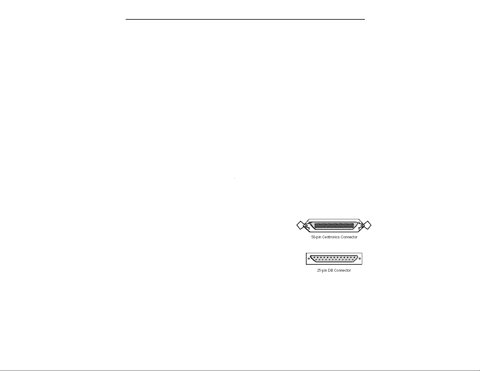
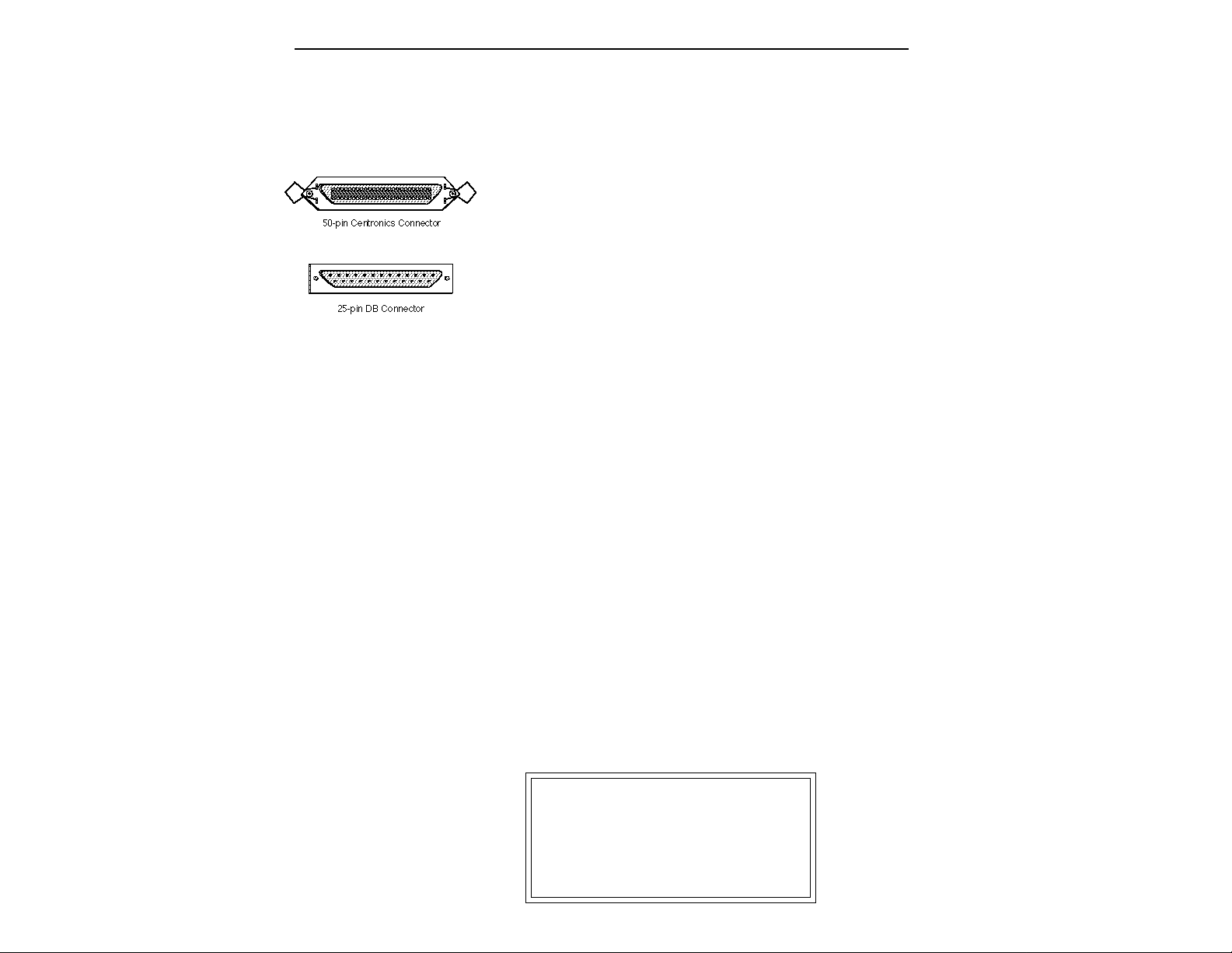
2. Connect the SCSI device to your EIIIX. Connect the EIIIX to
your SCSI system using a quality SCSI cable. There are two type of
SCSI cables in regular use: 50-pin Centronics type and the 25-pin DB
connector type. The EIIIX uses the Centronics type connector. If
your external SCSI device uses the DB connector you can use an
adaptor cable to eliminate the mismatch.
3. Turn on the external SCSI device.
4. Wait about five seconds, then apply power to the EIIIX. The
EIIIX should power up normally.
5. Check the SCSI connection. Press LOAD BANK. Use the data
slider to scroll through the available presets and press ENTER to
load the desired preset.
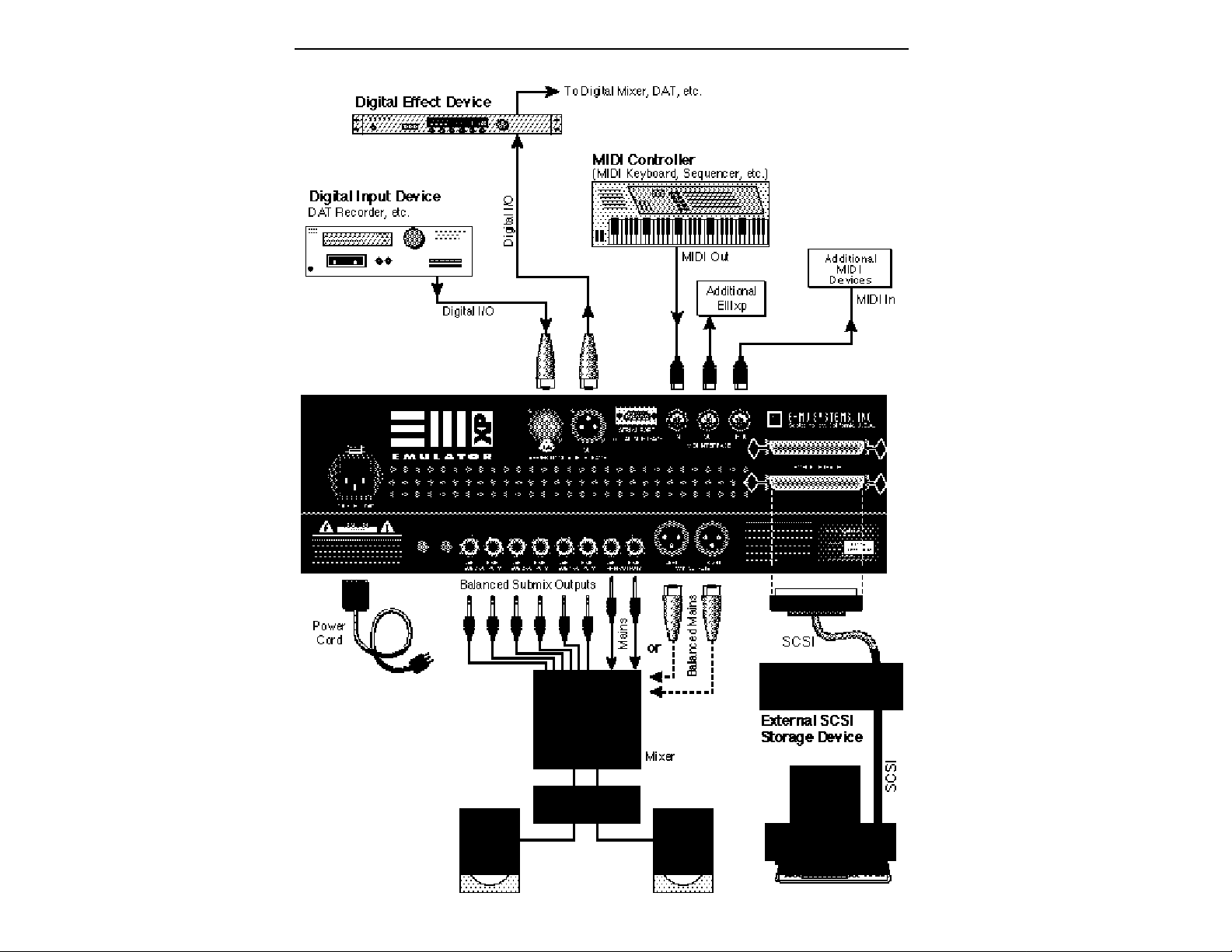
6. Connect the EIIIX to your audio mixer and MIDI setup.
■ If you are unfamiliar with
connecting a SCSI systems or
need additional information,
please refer to the section
“USING SCSI”.
▼ Turn all devices OFF whenever you change the SCSI
cable. Devices left on when
the cable is unplugged, may
not respond properly until
powered off and on.
Page 14
Connecting EIIIX to an Unformatted Hard Disk
1. Position the SCSI device and the EIIIX in a stable location.
Hard disk drives are particularly susceptible to shock and vibration. Make sure that you position your hard disk where it won't be
bumped or moved while in use.
2. Connect the SCSI device to your EIIIX. Connect the EIIIX to
your SCSI system using a quality SCSI cable. There are two type of
SCSI cables in regular use, 50-pin Centronics type and the 25-pin DB
connector type. The EIIIX uses the Centronics type connector. If
your external SCSI device uses the DB connector you can use an
adaptor cable to eliminate the mismatch.
3. Set the SCSI ID of your external SCSI device to any number
other then 5. (5 is the default ID of the EIIIX). Consult the operation
manual of your SCSI device for this procedure.
4. Turn on the external SCSI device.
■ Always use 50-pin
Centronics-type cables with
the EIIIX. These cables
have much better electrical
characteristics and have
fewer problems.
▼ Turn all devices OFF when-
ever you change the SCSI
cable. Devices left on when
the cable is unplugged, may
not respond properly until
powered off and on.
5. Insert the software floppy disk supplied with your EIIIX into the
floppy disk drive. Insert the disk, metal end first with the label side
up.
6. Apply power to the EIIIX. The EIIIX should power up normally.
It will wait a few seconds, then begin loading the floppy disk
software. Remove the floppy disk when the EIII has finished loading and put it aside in a safe place.
7. Make sure your hard disk really is unformatted. Formatting a
hard disk erases all the data on it. Press the Load button. If the
display reads, “No Valid Drives” the drive isn't formatted. Continue on to step eight.
8. Format the hard disk. Press the Master/Global button, then 77
on the numeric keypad. The display should read, “FORMAT
DISK”. Use the data slider to select your hard disk, then press
ENTER. The display asks, “Are You Sure?” Press the Inc/Yes
button to confirm. Formatting takes a few minutes. Time to take a
break.
9. Copy the floppy disk software onto the hard disk. Use the
Copy Software function (Master/Globals, 7, 4). The display shows:
COPY SOFTWARE from
D0 Floppy Drive
Select a Drive
Page 15

Press ENTER. The display now asks you to insert the software disk.
Insert the software disk supplied with your EIIIX. Press ENTER.
The display now shows:
COPY SOFTWARE from
D0 Floppy Drive
Erases Bank! OK? Y/N
Press the Inc/Yes button. (Don't worry. Since you haven't loaded
anything into the bank yet, there is nothing to be erased.) The software
will be loaded from the floppy disk into the EIIIX's memory. The
display now shows:
COPY SOFTWARE into
D0 Floppy Drive
D1 Hard Disk Name
Select a Drive
Your hard disk should be listed on line 3 of the display. If it is not,
use the data slider to select it. Press ENTER.
10. Reboot the System. Remove the floppy disk from the drive if
you haven't already. Turn off the EIIIX and the hard disk, then turn
both units back on. The EIIIX should now boot from your hard disk.
■ If you are unfamiliar with
connecting a SCSI systems or
need additional information,
please refer to the section
“USING SCSI”.
■ The EIIIX software should
not be copied to more than one
disk drive. The EIIIX will always boot from the drive with
the lowest ID number. Use the
Erase Software function
(MASTER, Disk Utilities, 9) to
remove the software from a
disk drive.
▼ Turn all devices OFF whenever you change the SCSI
cable. Devices left on when
the cable is unplugged, may
not respond properly until
powered off and on.
Put your software floppy disk in a safe place in case anything ever
goes wrong.
(You should make another copy of the software floppy disk as a
backup. Simply use the same formatting and software copying
procedure you just performed except that you choose floppy disk
instead of the hard disk when asked.)
Page 16
Page 17
CONNECTION INSTRUCTIONS
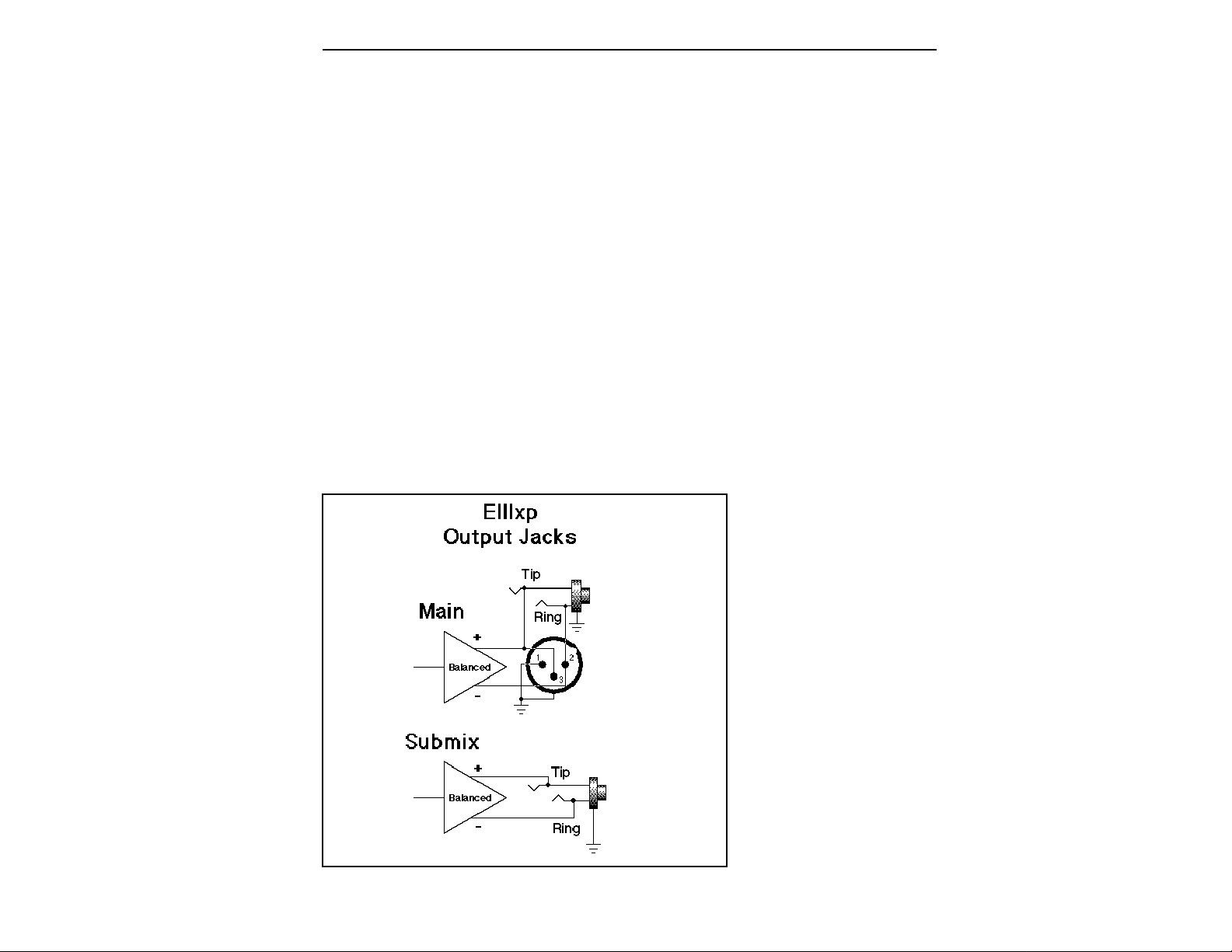
■ The submix outputs use a
“plug sensing” scheme which
re-routes the signal to the
main outputs if a plug is not
inserted.
Connecting to a Mixer
■ Main Outputs: The Emulator IIIX has provisions for a variety of
output connection schemes. The most common hookup will probably be using the main stereo outputs. The outputs of the EIIIX are
all balanced, but they can be used as unbalanced outputs by
grounding the negative pin. Output level is +4 dBm (approximately
12 volts p-p). Output impedance is 10Ω. The EIIIX will also drive
stereo headphones, which can be plugged directly into the headphone output on the front panel.
■ Submix Outputs: In addition to the main stereo outputs, the EIIIX
has three additional pairs of submix outputs that can be used when
individual processing on specific instruments is desired. These
outputs are all +4 dBm and are balanced. Output impedance is 10Ω.
Any combination of channels can be programmed to appear at any
of the submix output pairs (1, 2 or 3). Any keyboard zone (key range)
can be assigned to any submix pair using the Output Channel
function in the Dynamic Processing module. MIDI channels can be
assigned to submix outputs using the Multimode Mix function in
the Master/Globals module.
This diagram shows how the EIIIX output jacks are wired. The submix
outputs function as unbalanced outputs when a standard mono plug is
Page 18

Stereo Headphone Output
The headphone output is located on the left side of the front panel
and is capable of driving all types of stereo headphones. The output
level is controlled by the master volume slider.
MIDI Connection
The Emulator IIIX provides a MIDI IN, a MIDI OUT and a MIDI
THRU port.
■ The MIDI IN port on the EIIIX connects to the MIDI OUT port of
an external MIDI controller which could be a keyboard, a sequencer,
MIDI drum kit or whatever. Note that the EIIIX can only respond to
information that your controller transmits. If your MIDI keyboard
does not have velocity and pressure sensitivity, the EIIIX will not
respond to velocity and pressure.
■ MIDI OUT can be connected to another MIDI instrument or
computer. The MIDI OUT jack is used to transmit preset change
information, MIDI sample dump information (transfers sample
data) or for MIDI Overflow mode, which allows a second EIIIX to be
connected to the MIDI OUT to double the number of channels. See
Preset Definition, 6, MIDI for more details.
■ MIDI THRU simply re-transmits any information received at the
MIDI IN port. Use cords that have been designed specifically for
MIDI. While regular 5 pin DIN cords may work, they are not
shielded correctly for MIDI use and may cause ground loops
between equipment.
Digital I/O
The digital input and output jacks allow you to transfer audio back
and forth with other digital devices equipped with either AES/EBU
or S/PDIF digital I/O. The digital input allows you to sample
directly from a DAT recorder or other digital device. The digital
output reflects the data at the main outputs of the EIIIX. See the
Sample Management module and Main output Format (located
under Special in the Master/Globals menu) for more information.
SCSI
The SCSI connectors are high-speed parallel interfaces which are
normally used to interface the EIIIX with external mass storage
devices such as hard disks or magneto-optical discs. A SCSI port can
also be used to link the EIIIX with an external computer for extremely fast file transfers.
Page 19

For more information on SCSI installation, see the section, “Using
SCSI”. You may also want to refer to the operation manual that
accompanies your external SCSI device.
110V / 220V Operation
The Emulator IIIX may be used in either 110 volt or 220 volt
environments at either 50 Hz or 60 Hz. No change of voltage settings
is required. The EIIIX automatically switches itself for 100 or 220
Volt operation.
AC Power Connection and Fuse
The AC power connector is where the Emulator IIIX gets its power.
The fuse receptacle is located directly over the power receptacle.
Before changing or checking a fuse, UNPLUG the power cord. To
remove the fuse holder, squeeze the two tabs located on either side
of the fuse holder together. The fuse holder will now pop out with
its two fuses. The Emulator IIIX uses two 2-amp, 250 volt fast-blo
mini-fuses. The EIIIX should not normally blow fuses. If a fuse that
has been replaced blows again, do not attempt another replacement. Have the unit serviced!
Page 20
SAMPLING BASICS
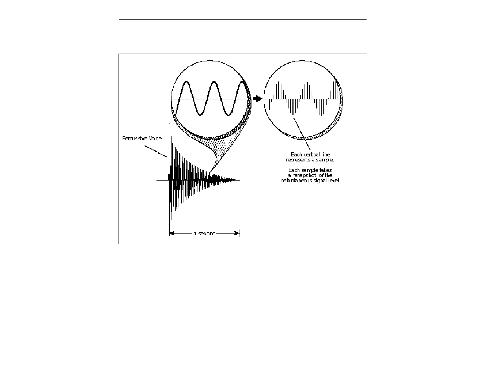
DIGITAL SAMPLING. The signal level is repeatedly measured at a high rate and the measurements stored
in digital memory. On playback, the measurements are converted back into voltages to reconstruct the
original waveform.
Throughout this manual we will use the terms and concepts described and defined below. Read through this section carefully,
even if you don’t retain it all. You can refer back periodically as you
read through the manual until you understand the basics and
definitions.
The Emulator IIIX is conceptually like a tape recorder. However, the
recording process is very different since the EIIIX digitally records
into its computer memory. Sounds for the EIIIX can be loaded via
removable-media hard disk, magneto-optical disk, CD-ROM using
the SCSI interface; or through the AES/EBU Digital interface; or
through MIDI using MIDI Sample Dump.
Page 21

Computers can accept information only in the form of numbers, so
first the EIIIX accepts audio signals coded into binary numbers.
Samplers work by examining (sampling) the incoming signal level
at a very high rate (44,100 times a second for compact discs), and
sequentially records these different levels in memory. Once stored,
these samples may be played back (in the proper sequence, of
course) to reconstruct the original signal. For instance, if a twosecond sound was being sampled at 44.1 kHz, it would require (2 X
44,100) or 88,200 samples to be recorded. As you might imagine,
shorter sounds require fewer samples.
A sound can be manipulated once it has been recorded. Playing
back the samples in reverse order from which they were stored
plays the sound backwards. Playing back the samples at a faster rate
than the rate at which they were stored raises the pitch. Playing back
at a slower rate lowers the pitch, much like a tape recorder’s variable
speed control.
How the Emulator IIIX Organizes Sounds
Sure, you’re anxious to start coaxing wonderful sounds from the
instrument—but the following is a necessary part of learning how
to play the Emulator IIIX. It is important to understand how the
EIIIX organizes sounds in order to make best use of the instrument
in the shortest possible time. Many terms will be introduced now
that show up later in the manual.
You can think of the EIIIX as resembling a collection of soundorganizing modules, all contained within an EIIIX bank. Pathways
indicate how information flows within the EIIIX. Let’s take a closer
look at what makes up this information, and how it is transferred
from one section of the instrument to another. We’ll start with
individual samples, then work our way through the system.
The Sample
Loading in any sound in mono or stereo creates a sample, the raw
material with which the EIIIX works. The total available sampling
time can be divided up any way you like—one long sample, lots of
short samples, a few medium samples, or any combination thereof.
The term sample commonly means two different things:
1) A digital recording of a complete sound, or
2) each snapshot of the sound that makes up the complete sample.
Confusing? You bet! In this manual, we’ll assume sample means the
complete recorded sound unless indicated otherwise.
Page 22

■ Since wide-range transposi-
tion alters the sample’s timbre,
it is often necessary to use
multiple samples and trans-
pose each one over a small
range to give the most realistic
sound. This is particularly true
with acoustic instruments.
DEFINITIONS
You can modify a raw sample in several ways:
■ Transposition: A sample can be transposed up or down in pitch
to cover a particular range of the keyboard. By doing this, it is not
necessary to record a sample for every key.
■ Digital Processing: Digital processing consists of Looping a
sample (allowing even short samples to play indefinitely).
■ Dynamic Processing: Just as synthesizers include signal proces-
sors (filter, voltage-controlled amplifier, envelope generators, LFO,
and so on) to modify the sounds produced by the synth’s oscillators,
the Emulator IIIX includes similar modules for modifying raw
samples or combinations of samples.
The Preset
As mentioned above, a sample can be assigned to a single note on
the keyboard, or transposed polyphonically to cover a wider keyboard range. A preset is one entire keyboard setup. The process of
assigning, and optionally transposing, samples to specific ranges of
the keyboard is called making a preset. Making a preset is a threestep process:
1. Create the preset and give it a number and name. The bank can
hold up to 256 Presets (000-255).
2. Place samples to different keyboard ranges. For example,
with five samples you could assign each sample to cover one octave
of the keyboard. A sample can be assigned more than once within
a given preset, and assigned to more than one preset.
3. Choose from a number of the available options that further
define the preset. Some examples are: assigning samples to par-
tially or fully overlap other samples, thus producing doubling
effects, or assigning dynamic control to individual samples in a
preset. You can modify zone parameters, add arpeggiation, and set
up MIDI and dynamic processing parameters.
Page 23
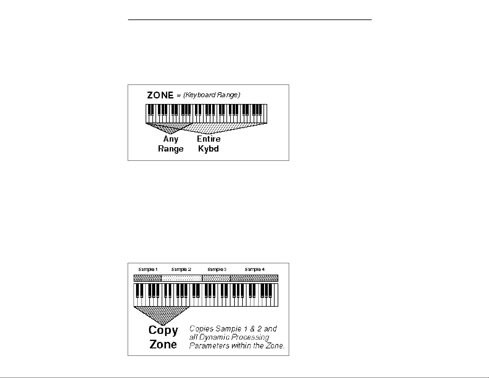
The Zone
A particular range of the keyboard is called a zone. This can
include one or more samples. The zone’s boundaries need not be the
same as the boundaries of the samples contained in the zone. Zones
free you from having to think about where the actual samples are
assigned. You just select a range of keyboard (a zone) and go!
As an example, suppose you wanted to set the velocity response for
the entire keyboard. You would first select the zone range by
playing the lowest and highest keys when prompted by the EIIIX.
Next you would set the velocity response (in the Dynamic Processing module). Done.
Now, suppose you wanted just the lower half of the keyboard to pan
from left to right as you play up the keyboard. You would simply
select a zone for the lower half of the keyboard, then change the pan
settings as desired.
When you copy a zone, the appropriate samples will be picked up
along with the Dynamic Processing parameters.
Page 24
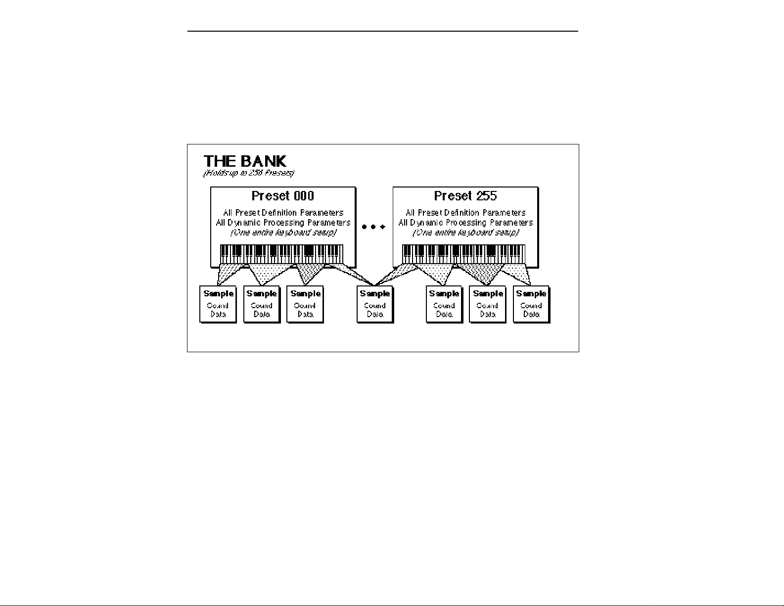
The Bank
The memory bank contains samples, zones and presets. Everything. Consider the bank as the central storehouse for all of the
Emulator IIIX’s data. Although the memory is volatile, meaning
that the data disappears when you turn off power, all bank data can
be saved permanently to the hard disk drive or other media to keep
a record of your work.
The Internal Drive
A disk drive is a mass-storage memory device that stores banks. The
Emulator IIIX has a built-in floppy disk drive which is used mainly
for operating system software. (The operating system of a computer
are the instructions that tell the computer what to do.) However,
other types of drives, as described below, can connect to the EIIIX to
provide sound storage.
■ Floppy Disk Drive (Drive 0): The floppy disk drive accommo-
dates 3.5", double-sided, double-density (DSDD) floppy disks. The
floppy drive on the EIIIX is used mainly as a convenient way to
periodically update the operating system software although it can
be used to load and save sounds. Because of the larger bank size of
the EIIIX, the floppy disk is not practical for backing-up sound data.
When the E-mu wizards come up with exciting new enhancements,
the new software is usually distributed on floppy disk. As described
later in the manual, this software can be copied on to a hard disk and
made a permanent part of the EIIIX.
Page 25

External Drives
The EIIIX includes a SCSI (Small Computer Systems Interface)
connector on the rear panel. This interface is commonly used in the
computer industry, so many devices made to work with computers—particularly mass storage devices—will also work with the
EIIIX. Here are some of the types of mass storage devices that can
plug into the EIIIX’s SCSI connector.
■ Hard Disk Drive: A hard disk provides the advantages of much
higher memory capacity and far faster access time. Transferring
data to and from the EIIIX is quite straightforward. However, you
cannot remove a hard disk and replace it with another one—the disk
is a permanent part of the drive. There are three main cautions
involved with hard disks:
■ Hard disks are sensitive to extreme mechanical shocks. If
your hard disk falls off a keyboard stand, chances are the
hard disk will be damaged.
■ Make sure power is not interrupted when you write data to
the hard disk.
■ Hard disks have reached a very high level of reliability.
However, they can fail from time to time (as can any part of
a computer), so any data should be backed up periodically
and regularly on some other medium.
■ Removable-media Hard Disk Drives: These are similar to normal
hard disk drives except that the disk itself can be removed and
replaced with another disk. Disk densities can range from 44
Mbytes to well over 100 Mbytes per platter. Removable-media hard
disk drives allow you to build a sound library of unlimited size and
are quite handy for transferring sounds between machines.
■ CD-ROM Drive: A CD-ROM is a playback-only (data cannot be
written to it) mass storage memory device whose capacity is approximately 660 Megabytes. Quality CD-ROM libraries are available from several companies. (Northstar, Optical Media International, E-mu Systems, Inc.) These can be loaded into the bank as
easily as you would load from a hard disk.
■ Magneto-Optical Drive: Basically a read/writable CD, these
high speed, high density storage devices are currently the hottest
thing around for storing large amounts of sound data. Typically a
magneto-optical drive can upwards of 300 Mb per side and the
removable cartridges can be used over and over. Disk access time is
comparable to a normal hard disk, and is sometimes even faster!
Advantages: High-speed, high-density, reliable, removable.
Disadvantage: High cost (although prices are dropping fast).
Page 26

ADDITIONAL DEFINITIONS
The Primary and Secondary Sample
An Emulator IIIX key provides for two channels. These contain the
primary and secondary samples. For example, the primary sample
might be a guitar note and the secondary sample a detuned version
of the same guitar note. When played together, you hear chorusing.
Also, a preset contains information about how the keyboard dynamics affect the primary and secondary samples. As an example,
the primary sample could be that of a drum hit played softly, and the
secondary of a drum hit played loudly. Thus, playing the keyboard
softly would play the primary sample, and playing the keyboard
more forcefully would play the secondary sample.
The Current Preset
When you load a bank, a preset will be ready to play and the display
will show the preset number. This is the current preset. If you select
another preset, or create a preset, that will become the current
preset.
The Current Sample
When loading an individual sample, you will need to specify the
sample number and name into which the sound should be recorded.
This is called the current sample.
■ If a module is already active,
and you are finished with one
submodule, you do not need to
re-activate the module—just
key in the new submodule
number.
Modules
A module controls a particular set of functions in the Emulator IIIX.
There are six main modules : Master/Globals, Preset Management,
Preset Definition, Sample Management, Digital Processing, and
Dynamic Processing.
■ Activating a Module and the Module Identifier: To work with a
module, you must first activate it. Press the button associated with
the desired module. The display will then show the Module Identifier and invite you to select a submodule.
■ Submodule: Each module contains several numbered
submodules that set controls for additional functions. There are two
ways to select a submodule within the module. You can move the
data slider until the display shows the desired submodule, then
press ENTER. As you work with the EIIIX, though, you will start to
memorize the submodule numbers and will probably find it faster
to simply key in the appropriate submodule number using the
numeric keypad. When using the keypad, it is not necessary to press
ENTER. Pressing either the module button or the Escape button
will cancel the operation.
Page 27

Saving
The bank only retains data for as long as the Emulator IIIX is
plugged in and turned on. Of course, we don’t expect you to leave
the thing on all the time, which brings us to the subject of saving
data.
Pressing the SAVE button on the Control Panel shuttles all the bank
data (samples and presets) to the drive of your choice . A hard disk
permanently stores data so that even after turning off the Emulator
IIIX, the disk will contain a record of your work.
IF YOU DO NOT SAVE A BANK, ALL BANK DATA WILL
BE LOST WHEN YOU TURN OFF THE MACHINE.
Do not wait until the end of a session to save. Save your work
periodically in case of power failure or some other unforeseen
circumstance that might erase the bank’s memory. Hard disks are
not infallible. All hard disk banks should be backed up periodically
to another hard disk or other media. Should you improve the preset,
sample, or sequence later, you can always replace the original with
the revised version. And if something goes wrong, the original will
still be available to save you the ordeal of starting from scratch.
Whenever you have done enough work that you would hate to
lose it, back it up!
Since the disk contains a record of the bank data, loading the disk
back into the bank transfers all the sample and preset data into the
bank. This will replace the existing bank data, if any.
Booting
Booting is a computer term that means “having the computer read
the software necessary for its operation from the disk.” (It’s easy to
see why this was shortened to booting.) The EIIIX automatically
boots itself from a hard disk when you turn it on. Once booted, the
instrument is ready to go. If the hard disk is damaged for some
reason, the EIIIX can be booted from a suitable floppy disk.
Default
A default setting is what we’ve judged to be a useful initial setting,
and remains in effect until you change it. For example, if you create
a new preset, the arpeggiator will default to Off. Had it defaulted to
the on position, all new presets would be arpeggiated.
■ If you want to maintain
compatability with the original
EIII, use function Master, 5
“Save as EIII Bank”. This will
allow the EIII to load your EIIIX
bank.
Page 28

The Cursor
The cursor is that small flashing line on the display. It sits under the
number or letter that will be altered if you enter data. Entering a new
value will overwrite the number or letter above the cursor, whereupon the cursor will move on to the next number or letter (if
applicable). If the EIIIX is expecting a two or three-digit number, in
most cases you must enter all the required digits even if some of
these are zeroes (called leading zeroes). For example, if the EIIIX is
expecting a three-digit number and you want to enter 8, you would
enter 008. If it is expecting a single-digit number, entering 8 would
be sufficient.
Data Slider & Increment/Decrement Buttons
In virtually all instances where the data slider selects options, the
Increment (Inc/Yes) and Decrement (Dec/No) switches duplicate
the slider. Press Inc/Yes to increase a value, or Dec/No to decrease.
Selecting
When the instructions say to select an option, you can use whatever
method is most comfortable for you: the data slider, the Increment/
Decrement buttons, the numeric keypad (if applicable) and, when
naming, the keyboard keys. Some functions do not implement all
these options; you can’t go wrong by trying, though. If a function
doesn’t respond to the numeric keypad, for instance, then pressing
the keypad will have no effect. Use the data slider or the Inc/Dec
buttons instead.
The Big Re-Cap
■ A sample is a raw sound that is loaded into the bank.
■ To create a new preset, make sure you have all the samples
required for the preset in the bank, number and name a preset, then
assign combinations of samples from the bank to specific sections of
the keyboard. By specifying one or more of these samples (or
portions thereof) as a zone, the zone may then be processed by the
EIIIX’s dynamic signal processors.
■ After arranging a bank, it can be saved to one or more drives.
■ Since loading from a hard disk fills the bank with samples and
presets, you can group these samples into new presets, process the
samples contained in particular zones, or alter existing presets.
Page 29

Page 30

Page 31

2-CONTROLS
MASTER VOLUME 2-2
DATA SLIDER 2-2
INC/DEC BUTTONS 2-2
TEN KEY PAD 2-2
ESCAPE 2-3
ENTER 2-3
AUDITION 2-4
CURSOR/PAGE 2-3
PRESET SELECTION 2-4
SAVE BANK 2-5
LOAD BANK 2-6
DRIVE SELECT 2-7
MULTIMODE 2-8
TRANSPOSE 2-9
Page 32

MASTER VOLUME
The Master Volume Slider controls the volume of every audio
output on the EIIIX including the submix and headphone outputs.
The master volume slider is a digital control. For maximum dynamic range it should be kept near the maximum position.
DATA SLIDER
Using the Data Slider is the most common way to change parameter
values on the EIIIX. Moving the slider changes either the data over
the flashing cursor or scrolls through options in the display.
INCREMENT/DECREMENT BUTTONS
On all EIIIX menus where the data slider selects options, the
Increment (Inc/Yes) and Decrement (Dec/No) Buttons duplicate
the slider function. The increment/decrement should be used when
a finer degree of control is required. They can also be used for
selecting Yes or No.
TEN KEY PAD
The Ten Key Pad is used to enter data in precise amounts. For
instance, if you wanted to jump to preset 10, enter 10 on the ten key
pad and the new preset number will be instantly selected, eliminating the process of finding the number with the data slider and then
pressing ENTER.
Page 33

The Escape button lets you back out of the module by one menu
each time the button is pressed. It can also be used anytime you do
not want to execute a particular function (bail out). In the Sample
Management module, pressing the Escape button terminates the
sampling process.
A flashing ENTER LED means that the EIIIX wants you to do
something, indicating either that data needs to be entered, or that
pressing the ENTER button will activate an operation. If the EN-
TER LED is lit steadily, pressing ENTER is optional. Doing so will
exit you from the function and return you to the Module Identifier.
You also have the option of going directly to another function
within the module.
The Audition Button allows you to play notes on the EIIIX directly
from the front panel without a MIDI keyboard being connected. The
note that will be played is selected from the Audition Key function,
located under Special in the Master/Globals module.
ESCAPE
ENTER
AUDITION
The Cursor is a small flashing line that appears in the display
window under the data that is currently being edited. The Cursor/
Page Buttons are used to move the cursor around in the display. The
buttons are marked with arrows to indicate the direction of movement. Some of the functions on the Emulator IIIX have more options
than will fit on a single page of the display. In this case the < and >
arrows become the Page selects, allowing you to move through the
various pages of the display.
CURSOR/PAGE
Page 34

CURSOR/
PAGE
The Cursor/Page keys perform the following functions:
1.Moving the cursor. To move the flashing cursor line in a particular direction in order to select a different function, simply press the
corresponding cursor key.
■ Selecting Presets using the
left and right cursor keys only
works when the EIIIX is NOT in
Multimode.
PRESET
SELECTION
2.Selecting the display page. In many submodules, a single
screen of the LCD cannot display all the available parameters.
Arrows (<- ->) in the display indicate that there are additional
screens which may be viewed by pressing the corresponding cursor
button.
3.Selecting presets. When no modules are selected, and the
cursor is placed under the preset number, presets may be
incremented or decremented by pressing the left and right cursor
buttons. This method is useful for live performance - arrange your
presets in the desired order, and step through them as needed.
4.Adding or deleting a space when naming. A quick and easy
way to add or delete a space when naming samples or presets is to
use the left and right cursor keys. The up key adds a space and the
down key deletes a space.
Selecting the Current Preset
With no modules active, the display will show the Current Preset
name and number on line 1 of the display. The blinking cursor will
appear under the preset number’s first digit. There are five ways to
change the Current Preset:
1. Enter a three-digit number with the keypad. If you enter a
number for which there is no Preset, the lower display line will
show the illegal Preset number and say Empty Preset. Try again.
2. Move the data slider or the increment buttons. The top display
line will continue to show the Current Preset, but the lower line will
scroll through the available Presets as you move the data slider.
When the lower line shows the Preset that you want as the Current
Preset, press ENTER.
3. Increment or decrement the Current Preset (as displayed in
the top line) with the left and right cursor buttons. This method
is useful for live performance—arrange your Presets in the desired
order, and step through them as needed.
4. Use a footswitch to advance through the presets.
5. Use a MIDI program change command. Receive Preset Change
must be enabled (Preset Definition, 6, MIDI).
To see the Current Preset number at any time, de-activate any active
modules and look at the display.
Page 35

A bank consists of presets and samples. The Save function saves this
data from the Emulator IIIX's memory bank to the floppy disk, hard
disk or other external SCSI device.
1. Press Save.
2. If necessary, select the drive top which the bank will be
saved. The EIIIX will default to the current drive. If you want to
choose a different drive, place the cursor under the drive number in
line two, select the appropriate drive and press ENTER.
SAVE BANK into
D1 Internal HD
Select a Drive
3. Select the bank number to which the bank will be saved, then
press ENTER. Empty banks are indicated as such, along with their
bank number on line three. Or, you can overwrite an existing bank.
SAVE BANK
■ If you want to maintain compatibility with the original EIII,
use function Master, 5 “Save
as EIII Bank”. This will allow
the EIII to load your EIIIX bank.
SAVE BANK into
D1 Internal HD
B00 Stereo Grand X
Select a Bank
EIIIX banks always have an “X” at the end of the bank name to
differentiate it from an EIII bank.
4. After pressing ENTER the bank will be saved. The display will
say: Saving Bank. The display will revert to the preset selection
screen.
▼ You cannot load and save
floppy disk files from the
original EIII.
Page 36

LOAD BANK
A bank consists of presets and samples. The Load function loads
this data into the Emulator IIIX's memory bank from the floppy
disk, hard disk or other external SCSI device.
1. Press Load.
2. If necessary, select the drive containing the bank to be
loaded. The EIIIX will default to the current drive. If you want to
choose a different drive, place the cursor under the drive number in
line two, select the appropriate drive and press ENTER.
LOAD BANK from
D1 Internal HD
Select a Drive
■ EIIIX banks will not load
into the original EIII. If you
want to maintain compatibil-
ity with the EIII, use function
Master, 5 “Save as EIII
Bank”. This will allow the EIII
to load your EIIIX bank.
▼ You cannot load and save
floppy disk files from the
original EIII.
3. Select the bank number that contains the bank to be loaded,
then press ENTER. The display will say: Loading Bank. After a
few seconds, the bank will be loaded. The display will revert to the
preset selection screen.
SAVE BANK from
D1 Internal HD
B00 Stereo Grand X
Select a Bank
EIIIX banks always have an “X” at the end of the bank name to
differentiate it from an EIII bank.
Page 37

The Drive Select Button selects which storage device will be used
when loading or saving. The Emulator IIIX may have an internal
hard disk and/or several external SCSI devices connected. Drive
Select allows you to select which storage device will be used.
1. Press Drive Select. The display shows:
DRIVE SELECT
D1 Sony SMO-C501
Select a Drive
2. Use the Data Slider or 10 Key Pad to select the desired drive,
then press ENTER. Any subsequent Load or Save operations will
now use the selected drive.
DRIVE SELECT
Page 38

MULTIMODE
The Multimode Button puts the Emulator IIIX into Multimode,
where it can receive on up to 16 MIDI channels at once. Multimode
is used for multi-timbral sequencing and when using a keyboard
that can transmit on more than one MIDI channel at a time. The
Multimode screen is where you assign presets to MIDI channels for
multi-timbral sequencing. You can also set the volume and stereo
pan position for each channel's preset.
1. Press Multimode. The display shows:
MIDI CHANNEL: 01
Volume: 127
Pan ∆ +00
000 Synth Flute
2. Use the cursor buttons to select one of the following parameters to edit. The volume, pan and preset can be programmed for
each of the 16 MIDI channels. Use the data slider or inc/dec buttons
to change the MIDI channel, Volume or Pan setting. If you do not
want the EIIIX to respond to certain MIDI channels, set the preset
for those channels to “Unassigned” which is located just below
preset 000.
▼ Pan∆ adds to the pan set-
tings made in the dynamic
processing module. Setting
the Dynamic Processing Pan
to 00 allows the Pan∆ param-
eter to have total control of
stereo positioning.
MIDI CHANNEL: 02
Volume: 116
Pan ∆ -01
Unassigned
3. After assigning the Preset, Volume and Pan setting for each
MIDI channel, press ENTER. The display will revert to the preset
selection screen.
Page 39

This function transposes the entire EIIIX in half-step intervals up to
± one octave. When in multimode, all channels will be transposed.
When the EIIIX is in Transpose mode, the Transpose LED will be lit
steadily. A new transposition can be selected at any time, regardless
of whether or not the Transpose LED is lit.
Some applications are:
■ Use one key's fingerings in a different key. Modulate to a different
key without having to use different fingerings.
■ Use transpose to easily reach hidden zones that lie beyond the
ends of the physical keyboard.
1. Press and hold Transpose. Its LED flashes, and the display
shows:
TRANSPOSE
TRANSPOSE
Play a Key
2. While holding Transpose, select the desired transposition
interval. All transpositions are referenced to C2, the second C from
the left hand side of the keyboard.
Some examples are:
■ To transpose down one octave, press C1.
■ To transpose up one octave, press C3.
■ To transpose up a fourth, press F2.
Note that pressing keys C#3-C4, C#4-C5, or C#5-C6 will, in each
case, produce the same effect as pressing keys C#2-C3.
Page 40

3. While holding Transpose, check the display to confirm the
transposition interval. Upward transpositions are indicated with
a + symbol, downward transpositions with a - symbol. For example,
if the EIIIX is transposed up a fifth, the display will show:
TRANSPOSE
+G
Play a Key
4. Release Transpose to retain the transposition. The Transpose
LED stays lit to remind you that the EIIIX is transposed.
5. To cancel the transposition, press and hold Transpose and
press C2. Display line three will go blank. Release Transpose and
the LED should now be off.
Page 41

Page 42

Page 43

3-GUIDED TOURS
EIIIX Modules 3-2
Guided Tour No. 1: 3-4
Meet the Emulator IIIX
Guided Tour No. 2: 3-7
Specifying the Current
Sample and Current Zone
Guided Tour No. 3: 1-9
Dynamic Processing
of a Zone
Guided Tour No. 4: 3-17
Realtime Control
Programming
Guided Tour No. 5: 3-20
Basic Sampling
Guided Tour No. 6: 3-24
Digital Processing
Guided Tour No. 7: 3-31
Managing the Bank
Guided Tour No. 8: 3-32
On Your Own
Page 44

THE EIIIX MODULAR SYSTEM
Each module of the Emulator IIIX affects a certain area of the
Emulator IIIX’s operation. You first select a module, then choose
which parameter with the module you wish to adjust.
Each module will be discussed in detail later on; the following is
intended mostly as background information.
■ Function Buttons: These are the buttons that get you going. Load
Bank and Enter load disk data into the EIIIX, Save Bank lets you save
your work to disk, and Transpose, as you probably suspect, transposes the keyboard.
■ Master/Globals: This module contains functions that affect the
overall keyboard or bank: Master Tune, Memory Available, Erase
Bank, Rename Bank Save as EIII Bank, various disk utilities, global
MIDI settings and the Special commands.
■ Sample Management: This module allows you to input sounds
from the digital I/O port or through MIDI into the bank.
■ Digital Processing: With this module, you may edit the loop (i.e.
infinitely sustain) any portion of the sample.
■ Preset Management: This module handles the preset “house-
keeping duties”, including load presets or entire banks from disk,
create, copy, rename, or erase presets and check on how much
memory space a preset uses up.
■ Preset Definition: This module lets you change parameters
within a given preset. You can set up the arpeggiator or MIDI
options, assign pitch bend and modulation wheels to control various
parameters in realtime, copy or erase zones, edit the sample assignment, and set some keyboard parameters (dynamics and crossfade
between overlapping samples).
■ Dynamic Processing: This module sets parameters that are
familiar to those who have worked with analog synthesizers. You
can set the dynamics by adjusting the VCA envelope, control timbre
using the VCF (filter) and its associated AHDSR envelope generator,
modulate the signal with the LFO, tie the keyboard velocity to
various parameters, set the tuning, attenuation, and delay for each
zone, and more.
Page 45

Activating a Module, Selecting Functions, and
De-activating a Module
Here is important background information on how to access the
various module functions. As the Guided Tours progress, this
information will relate to practical examples.
■ Activating: Each module has an associated switch. Most of these
are in the right-most section indicated by the blue bars next to the
buttons. Pushing the associated switch activates the module, and is
indicated by an LED next to the switch. Upon activation, the top line
of the display will show the Module Identifier (such as Master/
Globals, Preset Management, etc.). In some cases, upon activation
the display will ask you to specify the current zone or current sample
(as described in the next guided tour).
■ Selecting Functions: Each module includes a printed list of func-
tions on the front panel. These functions are available when the
module is active. To select a module function, key in its associated
number with the keypad.
■De-activating: When you’re finished with the module, either press
its button again to de-activate, or activate a new module. Pressing
the Escape button will move you back out of the module by one
menu.
■ Remember: if you want to
save modified presets, save
the altered bank to disk. Otherwise, any changes will be lost
as soon as power to the Emulator IIIX is interrupted.
■ Any time you make a mistake, get confused or otherwise "lost in the module" and
want to bail out, you can deactivate, then reactivate the
module and try again. The
Escape button works in a similar manner.
Page 46

Guided Tour No. 1: MEET THE EIIIX
Welcome to the Guided Tours! If you have just met the Emulator IIIX
for the first time, we suggest that you follow these tours until you
complete the Guided Tours section. This will get you up and running
on the EIIIX in the fastest possible time. Also, you’ll learn some tricks
in this section that will come in handy as you play some more with
the Emulator IIIX. This tour covers how to:
■ Load a Bank from the Hard Disk
■ Select Different Presets within the Bank
■ Load and Save to Floppy Disks
■ Tune the EIIIX to Other Instruments
■ Transpose the Keyboard
Loading a Bank From the Hard Disk
Press the Load button. The display says: Load Bank, and shows the
name and number of the current bank. Use the data slider to scroll
through the available hard disk banks. Stop when you find the bank
you want, then press ENTER.
An alternate method of loading a hard disk bank is to press Load,
then type in the number of the bank using the numeric keypad. The
display will show the current preset number and name. The cursor
will flash underneath the first digit. Start playing the keyboard and
adjust the master volume slider for a comfortable listening level.
Selecting Different Presets
The bank you just loaded contains several presets. To call up a new
current preset, use the up/down cursor buttons to position the
cursor under the preset number, then use the keypad underneath the
display. Note that leading zeroes must be entered for preset numbers (i.e. type 0, 0 and 2, not just 2, to call up preset 002). Now type
0, 0 then 2 on the keypad; these will replace the numbers indicated
by the flashing cursor.
Now call up more presets. If you enter a number for which there is
no preset, the display will list the entered preset number and say
“Empty Preset”. Try again.
Page 47

To scroll through the presets available in the bank, move the data
slider. The various preset names will scroll on the lower display line.
When this line shows the desired preset, press ENTER to make that
the current preset. This is an alternative preset selection method.
Yet another method is to use the left and right cursor buttons to
increment or decrement through the presets. This method allows
you to arrange your presets in the proper order, then access them
sequentially with a single press of a button.
When you’re ready to check out some more sounds, proceed.
Saving Data to a Hard Disk
The hard disk drive is used to make permanent backups of your
work. The capacity of the floppy drive is too small to make efficient
back-ups, therefore only the hard disk (or its equivalent) can be used
for sound storage.
■ To Save a Bank to Disk:
1. Press the Save button. Position the cursor under the drive
number in line two. Select the disk drive using the data slider. Press
ENTER.
2. Use the Data Slider to select an Empty Bank. Empty banks are
indicated as such, along with their bank number on line three. Saving
to a non-empty bank erases the bank that was previously saved
there.
3. Press ENTER to save the Bank. The display will revert to the
preset selection screen.
Tuning the EIIIX to Other Instruments
Refer to the Master/Globals module, 1. Master Tune. This function
demonstrates how the Emulator IIIX uses the data slider to adjust a
parameter. Play the keyboard while adjusting the data slider to
change the overall tuning.
Page 48

Transposing the Keyboard
Refer to the function button Transpose. While holding the transpose
button, play a key on the keyboard in the lower two octaves. The
second C from the bottom (C2) corresponds to normal or no transposition. All transpositions are based from this C2 key. For example,
pressing the G key above C2 will transpose the keyboard up a perfect
fifth. If the keyboard has been transposed, the transpose LED will
stay lit. Press and hold the transpose button while pressing C2 to
return to normal transposition.
Page 49

Guided Tour No. 2: SPECIFYING THE
CURRENT SAMPLE and THE CURRENT ZONE
The Emulator IIIX has two modules dedicated exclusively to processing samples within a preset: Digital Processing and Sample
Management. Each sample stored in a bank can be processed by the
Digital Processing module independently. Therefore, we need a way
to specify the current sample, which is the individual sample to be
processed.
The concept of the current sample is important. To process one
sample out of a preset, assign the current sample to be that one
sample, and process it.
Zones are sections of the keyboard which can be selected to apply
Dynamic Processing parameters or to be copied, erased or loaded
from another preset. A copied zone contains samples as well as
analog parameters. A zone can be one key or the entire keyboard
range.
■ To Identify Which Keyboard Keys Belong to Which Sample:
1. Activate the Preset Definition module.
2. Select 2. Edit Assignment.
EDIT ASSIGNMENT
P00 pri D2
p01 Sample Name
No Secondary Sample
3. Play a key on the keyboard. Line two shows the preset number
and the last key pressed. Line three shows the primary sample
assigned to the key, and line four shows the secondary sample, if
any, assigned to the key. As you run your fingers up and down the
keyboard, the primary and or secondary sample numbers will
change indicating the keyboard range of those samples. Moving the
data slider will also show you the sample boundaries.
Page 50

4. Choose a sample and press ENTER. The display now shows the
range of the current zone on the upper line of the display. Don’t play
any keys but press ENTER again. Now the display shows something
like this, where XX is the name of the key (such as D2).
EDIT ASSIGNMENT
Zone: XX to XX
Select High Key
Specifying the Zone of the Dynamic Processing Module
Now that we know how many samples there are in the preset, and
the range covered by each sample, let’s specify a range of keys to be
altered by the Dynamic Processing Module, starting with the lowest
key.
1. Activate the Dynamic Processing module.
2. Select 0. Select Zone.
3. Specify the range of the zone. The display instructs you to
“Select Low Key”. Press the lowest key on the keyboard, then press
the ENTER button (whose LED is now flashing). The display then
instructs you to “Select High Key”. Press a key on the keyboard near
the top of the keyboard, then press ENTER. The display now shows
the current zone and prompts you to “Select a Submodule”.
At this point, you can begin modifying the sounds in the bank with
the Dynamic Processing module. The assigned current zone will
remain as is until you either change the current zone assignment,
change presets, or load another bank. If you switch between modules, the current zone remains as assigned (unless you select the
Digital Processing Module, which will be a subject of a later tour).
Before proceeding, look over Dynamic Processing, 0. Select Zone to
help reinforce what you’ve learned. Now that you know what a zone
is and how to specify it, we’ve reached the end of this tour. Feel free
to come back any time to refresh your memory. In the next tour, we’ll
see how to modify samples with the Dynamic Processing section.
Page 51
Guided Tour No. 3: DYNAMIC PROCESSING
OF A ZONE
The Dynamic Processing module consists of several interesting
sound processing functions. Let’s start with the Filter and VCA
sections, as they are among the most important.
The VCA function contains 32 Voltage Controlled Amplifiers that
control the amplitude envelope of a sound. The filter function
contains 32 Voltage Controlled Filters that control the timbre of a
sound. (Note: The voltage controlled filters and amplifiers are actually
implemented digitally. The names VCF and VCA are kept for EIII compatibility.)
Working with the Filter
You could activate the Filter Setup function directly by keying in 3.
However, let’s investigate another way to select the filter function.
Move the data slider to catalog the various Dynamic Processing
functions. When the display shows function 3. VCF, press ENTER.
■ To Change the Filter Cutoff Frequency:
1. Activate the Dynamic Processing module, 3. VCF. The display
should look something like this:
VCF
Cutoff: 74040 Hz
Q: 0%
Play with the up and down cursor buttons. Note how you can move
the cursor under the various parameters to be adjusted. For now,
move the cursor under the Cutoff frequency on line three.
2. Select the filter cutoff frequency. To do this, vary the data slider.
Note how the numbers to the right of cutoff change. Lower numbers
mean a lower filter cutoff frequency (less high frequencies). Higher
numbers mean a higher filter cutoff frequency (more high frequencies). Observe how only the notes within the current zone are
affected by the slider setting.
■ You must re-trigger a note to
hear any changes. Holding
down a note and playing the
slider will not change the
sound; you must play the note
after changing the slider to
hear the results. This is true
when making any changes to
the sound, not just while you’re
in the filter function or the Dynamic Processing Module.
Page 52
Now might be a good time to mention that although we are changing
the sounds in the bank, the sounds on the disk remain unchanged.
This is because we haven’t saved the bank to disk. You can fool
around with the bank sounds as much as you want without having
to worry about altering the original sounds on the disk.
■ To Change Filter Q:
VCF
Cutoff: 22049 Hz
Q: 0%
1. Move the cursor to the Q% on line four. Vary the slider to change
the sharpness of the sound. Higher numbers give a sharper sound.
Again, this affects only the range of notes covered by the current
zone. Set the Q at about 60 and proceed.
2. Move the cursor back to Cutoff on line three. Vary the data
slider. Note how this produces a sort of wa-wa effect. Remember,
you have to re-trigger the key to hear the results of changing the Q.
Set Cutoff to 200 Hz and Q to about 50. The range of notes covered
by the current zone should sound muted.
■ To Change the Filter Cutoff Envelope:
1. Select page two by pressing the right cursor arrow.
VCF
Tracking: +1.00
Envelope Amt: 0%
Investigate the effects of envelope control over the filtered sound by
moving the cursor to the Envelope Amount. Use the slider to set a
value of +40%. This allows the envelope to control the filter cutoff
frequency.
Page 53

2. Select page three by pressing the right cursor.
VCF Attack: 0.20s
Hold: 0.00s
Decay: 0.00s
Sustain:99% Rel:0.40s
Move the cursor under the Attack time on line one and vary the
slider. With larger values, it will take more attack time for the filter
frequency to go from lowest to highest cutoff frequency. Vary the
various envelope parameters, and observe the effect these changes
have on the sound.
To check out inverted envelopes, set the envelope parameters as
follows:
VCF Attack: 0.20s
Hold: 0.00s
Decay: 0.00s
Sustain:99% Rel:0.40s
Play and hold a chord. This is a non-inverting envelope in the sense
that the envelope increases the filter cutoff frequency above the
initial cutoff. To select an inverting envelope where the cutoff
decreases below the initial cutoff, press the left cursor arrow.
VCF
Tracking: +1.00
Envelope Amt: 0%
3. Move the cursor to Envelope Amount and select -40% to invert
the envelope. The envelope effect is not all that noticeable when you
play a chord. This is because the envelope forces the cutoff frequency
Page 54

in a negative direction. Since the cutoff frequency is already fairly
low, it can’t go that much lower. Now go back to the cutoff frequency
and increase it. The effect will be far more noticeable since there will
be more range available for the negative going envelope excursion.
If you feel like experimenting, play with the Tracking control to
affect the way the filter frequency tracks the keyboard pitch.
Before proceeding with the tour, set Cutoff Frequency to 22049, Q to
00, Envelope Amount to +00, and Tracking to 1.00. Set the envelope
Attack to 0.00s, Hold to 0.00s, Decay to 0.00s, Sustain to 100%, and
Release to 0.49s. After entering these values, press ENTER to return
to the Module Identifier.
Fun With Voltage Controlled Amplifiers
In preparation for the following experiments, let’s change the
Current Zone to include the entire keyboard.
1. Select Submodule 0. Select Zone. Move the data slider to the
bottom of its travel and press ENTER. Now move the data slider to
the top of its travel and press ENTER again. You have now specified
the entire keyboard as the current zone.
2. Select the 2. VCA function. The display shows:
VCA
Level: 100%
Pan: + 0%
L | R
3. Select the next page of the VCA controls with the right cursor.
VCA Attack: 0.20s
Hold: 0.00s
Decay: 0.30s
Sustain:50% Rel:0.60s
Page 55

Move the cursor under the various envelope parameters and observe how different settings affect the sound. Before moving on,
make sure you have a sound that is fairly sustained with little or no
envelope attack time.
Other Dynamic Processing Options
1. Select 1. Setup. Note how the tuning, delay, and chorus controls
affect the sound.
2. Add some Low Frequency Oscillator effects. Select the 4. LFO
function. The display shows:
LFO
Rate: 4.25Hz
Shape: triangle
Delay: 0.00s
If the LFO rate is different, change the rate so that it is about 4.25 Hz.
3. Use the right cursor/page button to move to the next page of
the LFO controls. The display will show something like this:
LFO
Variation: 0%
LFO->Pitch: 0%
LFO->Cutoff 0%
Position the cursor under each display option. Vary the data slider
and observe how this affects the sound. Adding LFO to Cutoff might
not sound all that noticeable. If you want a more obvious effect,
bounce back to function 3. VCF and set the Cutoff to about 200 Hz
and Q to about 50. This should make the LFOs effect more noticeable.
Page 56

4. Select page three of the LFO controls. The display will show:
If the LFO settings aren’t to your liking, use the left cursor/page
button to change the LFO rate, delay, and variation.
LFO
LFO->Pitch: 0%
LFO->Cutoff 0%
The Auxiliary Envelope
1. Select 5. Auxiliary Envelope. The display shows the first page:
Move the cursor under Destination on line two, and use the data
AUXILIARY ENVELOPE
Dest: off
Envelope Amt: 0%
slider to scroll through the auxiliary envelope destinations. Select
Pitch as the destination, then set the Envelope Amount to -50%.
2. Select the next page using the right cursor. Set the parameters
so that the display looks like this:
AUX Attack: 0.00s
Hold: 0.00s
Decay: 0.40s
Sustain:99% Rel:1.65s
Page 57

Now play the keyboard. Notes will bend up, since we are using an
inverted envelope, to pitch and then hold there. This is an effect
common in many natural sounds.
Vary the various envelope parameters, and observe the effect these
changes have on the sound.
Understanding Velocity
By now you probably have a pretty messy sound as a result of all
these exercises. Let’s start with a clean slate.
1. Press the Load Bank button, then ENTER to re-load the bank.
2. When the bank is loaded, activate the Dynamic Processing
module.
3. Specify a zone. Let’s make the entire keyboard the current zone.
Since the default zone is the entire keyboard we don’t have to do
anything!
4. Select 6. Velocity To. The display will look something like this:
VELOCITY TO
Pitch: +0%
VCA Level: +0%
VCA Attack: +0%
Moving on to the next velocity page we see:
VELOCITY TO
VCF Cutoff: +0%
VCF Q: +0%
VCF Attack: +0%
Page 58

Moving on to the last velocity page we see:
VELOCITY TO
Pan: +0%
Sample Start: +0%
Auxiliary Env: +0%
Move the slider to select different values, and note the effects. With
positive velocity sent to the VCA, the EIIIX plays softer as you play
softer. In other words, the EIIIX equates harder play with the
nominal volume setting and goes down from there as you play
softer.
Continue to move the cursor to the other available parameters and
vary the slider. Notice that the filter cutoff frequency lowers as you
play softer. The amount downward change is dependent on the
value in the display.
Filter Q is affected differently than Level or Filter Cutoff. It raises
from the initial setting as you play harder. Also, note that velocity
can be set to affect Q inversely. In other words, if the filter is set to a
high Q setting, playing harder on the keyboard will lower the Q.
Remember that the velocity-to-envelope Attack setting interacts
with the initial envelope Attack settings. Call up the envelope Attack
parameters for the filter and VCA and see how different values
interact with different velocity values.
Page 59

Guided Tour No. 4: REALTIME CONTROL
PROGRAMMING
Ever wanted to add vibrato to a grand piano? Or bend its pitch? The
Realtime Control functions in the Preset Definition module can do
this, and lots more.
Pitch-Bending
First, let’s check out pitch-bending. Pitch-bend can be enabled or
disabled for any zone within a preset. Let’s have pitch bend affect
only the lower half of the keyboard. Activate Dynamic Processing,
0. Select Zone. Specify the upper half of the keyboard as the current
zone.
Next key in Dynamic Processing, 8. Realtime Control Enable. Use
the cursor/page buttons to see a list of modulation destinations.
Pitch will be set to On. Press Off, and like magic, you can now pitchbend only the lower half of the keyboard. If modulation does not
seem to be affecting a zone, make sure that modulation is enabled.
Want to change the pitch bend range? Activate the Preset Definition
module, 6. MIDI.
Modulation Wheel Destinations
The Emulator IIIX offers two modulation options: Pre-programmed,
which adds a constant, selectable amount of modulation, and Realtime, where the player adds in modulation by using one of the
wheels or other controller.
Each Emulator IIIX wheel can be assigned to a particular destination.
For example, if the left wheel is assigned to pitch, then rotating the
wheel bends pitch. If assigned to the filter, rotating the wheel varies
the cutoff frequency.
Let’s set up for the next part of the tour. Choose preset 01 as the
current preset if it is not already selected. Activate the Dynamic
Processing module and assign the entire keyboard as the current
zone if necessary. Select 8. Realtime Control Enable. Use the cursor/
page buttons to select On for all of the Enable options. This will make
it easier to hear the results of the next series of experiments.
Page 60

Now activate the Preset Definition module, 0. Realtime Controls. To
make “live” playing as simple as possible, the display works somewhat differently for this module. The display shows:
REALTIME CONTROLS
1 Left Wheel
1 Pitch
Select a Controller
Use the data slider to scroll through the available Realtime Control
sources and their currently assigned destinations.
■ Emulator IIIX Control Sources
1: Left Wheel
2: Right Wheel
3: Pressure
4: Control Pedal (plugs into rear panel pedal jack)
5: MIDI Control A (can be assigned to any MIDI controller #)
6: MIDI Control B (can be assigned to any MIDI controller #)
7: Footswitch 1 (on your MIDI controller)
8: Footswitch 2 (on your MIDI controller)
■ Emulator IIIX Modulation Destinations
0: Off 5: LFO -> Cutoff
1: Pitch 6: LFO ->VCA
2: VCF Cutoff 7: Pan
3: VCA Level 8: Attack
4: LFO->Pitch 9: Crossfade
■ EIIIX Footswitch Destinations
0: Off 4: Arpeggiator Latch
1: Sustain 5: Preset Increment
2: Cross/Switch 6: Preset Decrement
3: Arpeggiator On/Off
Each of the modulation destinations (0-9) can be controlled by
control source 1, 2, 3, or 4, or via data sent over MIDI. Each of the
footswitch destinations (0-6) can be controlled by sources 7 and 8.
You’ll be happy to know that Realtime Control settings are memorized for each individual preset, so if desired, each preset can react
to the Realtime controls and MIDI controllers in different ways.
Page 61

Selecting a Control Source and Destination
1. Activate the Preset Definition module, 0. Realtime Controls.
2. Select the left wheel as a control source. Move the cursor down
to the next line. The display will direct you to “Select a Destination”.
The left wheel should be assigned to 1: Pitch. Vary the wheel and
check that the keyboard pitch is indeed affected. If sections of the
keyboard are not affected, check that pitch control is enabled (Dynamic Processing, 8. Realtime Control Enable).
Now try assigning the left wheel to 2: VCF Cutoff. Rotating the wheel
towards you should produce a more muted sound.
If you assign 3: VCA Level, the left wheel will affect overall volume.
If you feel adventurous, check out the other control destinations.
Note that if you select a destination that is already specified for one
of the other control sources, the old assignment will be de-selected
and that control source will be turned off (0).
Think about it for a bit... the left wheel can control a destination, the
right wheel can control a different one (as can the pedal), and there
are MIDI control possibilities as well. These assignments can be
different for each preset, and particular controller destinations can
be disabled for different presets and samples. We’re talking versatile
here, so if you feel like taking out the next couple of hours and
checking out all the possibilities, by all means, do so!
Oh yes, and there are footswitches too. But before experimenting
with the footswitches (sources 7 and 8), we need to understand the
difference between looped and unlooped sounds. Basically, a sustain looped sound is one where a portion of the sound is put into an
infinite repeat loop for as long as you hold down the key. This is
similar to the infinite repeat function on digital delay lines. Looping
allows you to sustain a normally non-sustaining sound for as long as
you like. An unlooped sound is not artificially sustained, and therefore lasts its normal length.
■ One control source can control up to six destinations. This
can be done by setting more
than one source to the same
controller number in the MIDI
submodule (Preset Definition,
6).
For example, by setting right
wheel and pressure to 01, (in
the MIDI submodule) the mod.
wheel on your controller will
now control two sources in the
realtime controls submodule.
Keeping this in mind, refer to the Preset Definition module, 0.
Realtime Controls, footswitch destinations 0-6. Assign various functions to the footswitches. You will find that some sounds lend
themselves to the sustain function better than other sounds, and we
heartily encourage you to experiment.
Page 62

Guided Tour No. 5: BASIC SAMPLING
Sampling involves more than just sticking a microphone in front of
something—sampling is an art. This guided tour gives you the
basics, and also lays the groundwork for the guided tour of the
Digital Processing Module. In preparation for this guided tour,
please read section 5, Sample Management module.
■ To connect the EIIIX to S/
PDIF format machines, an
adapter cable wired as shown
above shoud be used. Always
use video-grade cabling when
connecting digital I/O.
Sampling with a DAT Recorder
The EIIIX can sample from either analog or digital sources. Your
EIIIX may or may or may not be equipped with the optional analog
inputs. Without the analog inputs youwill need to have some sort of
device with a digital audio output such as a DAT or stand-alone
A/D converter unit. To sample from a DAT recorder, connect the
digital output of the DAT to the digital input of the EIIIX. Either the
AES/EBU or the consumer S/PDIF formats can be used. By putting
the DAT recorder in record/pause mode you can sample directly
into the EIIIX just as if it had analog sample inputs. Playing a DAT
tape works the same way. For this tour, plug a microphone into the
DAT recorder.
Sampling with the Optional Analog Inputs
If you wish to use the analog sampling inputs for this guided tour,
simply connect a microphone directly to either the left or right
analog input.
■ To connect a standard XLR
type microhone to the analog
input of the EIIIX, an adapter
cable wired as shown above
should be used.
1. Activate the Master/Globals module.
2. Select 3. Erase Bank. Answer Yes to the display's query. This
clears out the memory, which gives us maximum sampling time.
3. Activate the Sample Management Module, 5. Setup. The
display shows:
SETUP Gain: -10dB
Thresh: |
L: on |
R: on |
Page 63

If you are sampling in mono, move the cursor to the input that you
are not using and turn it off with the On/Off buttons. Otherwise,
leave both channels on.
4. Use the right cursor/page button to view the next page of the
Setup section.
SAMPLE SETUP
Source: Digital44.1K
Length: 5.5secs
200.8 secs Available
Check the available sampling time. This will vary depending on how
much memory you have in your EIIIX.
5. Change the source using the data slider to match the type of
input you are using. If you are using the analog sample inputs, set
the source to either Analog 29.4 kHz or Analog 44.1 kHz. If you are
using the digital inputs, set the source to Digital 32 kHz, 44.1 kHz or
48 kHz to match the sample rate of your input device. (If the digital
sample is set incorrectly the sample will play back at the wrong
pitch.)
6. Use the right cursor/page button to go back to the first page.
SETUP Gain: -10dB
Thresh: |
L: on |
R: on |
With the connection peak into the microphone, you should see the
VU meter move, indicating that the EIIIX is receiving signal.
If you are using the analog inputs, place the cursur on line one of the
display and use the data slider to adjust the input gain. Speak into the
microphone and observe the bar graph display. Adjust the gain so
that the peak bar comes close to the extreme right side without
actually reaching it. (The gain control has no effect on the digital
input.)
Page 64

If you are using a DAT recorder, make sure the DAT is in record/
pause mode. You should see the bar graph display move as you
speak into the mic; if not, check your connections.
7. Go on to the third page of Sample Setup by pressing the right
cursor button twice. The display shows:
SAMPLE SETUP(Auto)
Truncate: off
Normalize: off
Placement: 12keys
Set the automatic parameters as shown. The auto-placement parameter determines where the samples we are going to take will be
automatically placed. In this case, with auto-placement set at 12
keys, the first sample will be placed on the lowest octave (C1 to B1),
the next sample on the next octave up (C2 to B2), and so on.
8. Go back to the first page and set the Threshold using the data
slider. Set it up a few bars from the bottom so that the EIIIX does not
trigger on the ambient room noise. Press ENTER to return to the
Module Identifier.
9. Select 7. Arm Sampling. You’re ready to sample! Speak into the
microphone. As soon as the level exceeds the threshold, the display
will say “Sampling.” Chat away freely . If you run out of inspiration,
press Escape to stop sampling.
More Sampling
Continue to experiment with sampling. Try setting a particular
sample length, or using forced sampling instead of threshold-sensitive sampling, or assigning the sampled sound to other portions of
the keyboard. Also, practice terminating the sampling process.
Let’s try another sample. Notice that the EIIIX, will overwrite the
existing sample unless you exit an re-enter the sample module. The
new sample is automatically assigned to the next higher octave. This
assignment can always be modified in the Sample Management
module, 6. Place Sample.
Page 65

Saving the Sample
To save the sample as part of a preset, de-activate the Sample/
Management module. Since memory was cleared prior to sampling,
the EIIIX created a preset (00) called “Untitled Preset.” This is the
preset that holds your new sample. Had you sampled into a bank
with existing presets, the sample would have been stored with the
current preset.
Remember, this guided tour is intended simply as an overview to
give you a feel for the sampling process. Good sampling requires
skill, patience, and above all, practice!
Page 66

Guided Tour No. 6: DIGITAL PROCESSING
Background and Setup
Digital processing allows you loop samples stored in the bank. In
this guided tour we’ll learn how to do this. First, though, we need to
create a couple of samples with which we can practice.
1. Clear the bank of memory. Use the Master/Globals module, 3.
Erase Bank.
2. Make a sample of yourself speaking. Following the directions
in Guided Tour No. 5, select a four second sample length (Sample
Management module, 5. Setup). After setting the threshold and
other parameters, arm sampling and start jabbering.
3. Take another four second sample. De-activate, then re-activate
the module to sample. You will not have to do any setup — just hit
7. Arm Sampling, and talk away. You will then have two samples
suitable for experimentation.
4. Assign your samples to a keyboard zone. Use 6. Place Sample.
Choosing the Current Sample
Activate the Digital Processing module. This module acts upon the
current sample. To select another sample, press 0. Select Sample.
Truncating A Sample
Use the Digital Processing module, 3. Truncation, to truncate the
ends off samples. Vary the data slider as you play a key in the range
assigned to the current sample. Notice the start of the sample will
disappear. Use this technique to get rid of silence at the start of a
sample or for effects. Move the cursor using the up and down arrow
keys to the End display. Use the data slider to truncate any undesired
part off the end of the sample.
When you are satisfied with your truncating efforts, press ENTER.
The EIII makes a backup of the sample on the hard disk, in case you
decide that you don’t like the truncation after all.
If desired, change the current sample (Digital Processing, 0. Select
Sample) and experiment with truncating the other sample you took.
Page 67

Looping A Sample
If you haven’t yet done so, activate the Digital Processing Module
and assign the current sample.
1. Select 2. Loop to graphically see how looping affects a
sample. Since the loop function is on, if you play and hold a key in
the current sample, it will play indefinitely.
2. Try modifying the loop. Adjust the Start and Length values. Note
that if the length equals the full length of the sample, you will not be
able to set a new start point. Reduce the length, and you should be
able to adjust the start point. For practice, try looping individual
words or sentence fragments.
A Practice Sampling Session
Plug a microphone into the rear panel right Sample Input jack (or
through a DAT into the digital I/O).
1. Erase all memory (Master/Globals, 3. Erase Bank).
2. Set the Sample Source for either Analog or Digital sampling
(Sample Management, 5. Setup). “Source” is located on the second
page in the Setup submodule. If you are using the digital inputs,
match the sample rate to that of your DAT recorder or the sample will
play back at the wrong pitch.
3. Set the level (Sample Management, 5. Setup). Sing Ahhhh into
the microphone. (This is an easy sound to loop.) The VU level should
not quite reach the top of its range. Adjust the gain using the data
slider, until a good level is attained.
4. Set the threshold (Sample Management, 5. Setup). This should
be set about five or six bars from the left. When the input sound
exceeds this level, recording will start.
5. Select 7. Arm Sampling, to arm the sampling process. OK,
now get ready to sing Ahhhhh.
6. Sing Ahhhhh! When you are out of breath, press ENTER to stop
sampling.
7. Play the keyboard in the assigned range to hear the results.
The sound should default to the lower keyboard range, C1-B1.
8. Truncate the silence off of the beginning and end of the
sound. Activate the Digital Processing module. The EIIIX will
default to the only sample in the unit, which is the one you just made.
Page 68

Now select 3, Truncation to enable the truncation function. Adjust
the start and end points by moving the slider to remove any silence
or unwanted portion of the sound. You must play the keyboard after
you move the data slider in order to hear the results of the slider
change. Press ENTER, then No to exit truncation.
9. Activate the Digital Processing module, 2. Loop. Now we are
ready to loop the sound.
To loop, first move the data slider to make the loop length about half
a second long. Next, move the start point into the sustained portion
of the ahhh sound so that the ticking sound becomes softer. The idea
is to loop the “hhh” portion of the “ahhh” but not the “a “ part. The
loop length can be adjusted so that it matches the rhythm or wavering of the sound. When you get a fairly good loop press ENTER. The
display says: “Auto Correlate? Y/N.” Press Yes. You now should
have a fairly good loop. If not, adjust the start point and again Auto
Correlate. It takes practice, but you’ll get it.
That’s it! Feel free to play around with other digital and dynamic
processors such as the filter, chorus and LFO.
So basically, these are the steps you will go through every time you
have a sampling session:
■ Take the sample
■ Truncate the sample
■ Loop the sample, if desired
■ Assign the sample to a keyboard position
■ Continue to refine and make presets
Of course, you will probably develop your own order and style of
sampling techniques.
The purpose of this guided tour is to acquaint you with the concept
of looping. There is much more to the subject than simply fooling
around with looping words from a spoken sample. Please remember
too that looping is a very complex process which requires a great
deal of practice to achieve proficiency. The best way to fully understand looping is to experiment with a variety of signals.
Time To Save?
Maybe you haven’t created any masterpieces during these
experiments...but maybe you have. If you want to save a preset to
disk, by all means do so.
Page 69

More Digital Magic
Let’s play The Backwards Talking Game! In preparation for this fun,
erase all memory (Master/Globals, 3. Erase Bank), then take a
sample of your voice speaking your own name.
1. Activate the Digital Processing Module.
2. Select 1. Playback Setup. The display shows:
PLAYBACK SETUP
Loop Type: forward
Loop in Release: on
Reverse Playback:off
3. Move the cursor to Reverse Playback and select on. Now play
the sample back. It is backwards! Now practice saying your name
backwards until you feel that you have learned it well. Think you’ve
got it, do you? OK, now sample yourself saying the reversed version
of your name, and then of course..... reverse that. We guarantee loads
of fun and maybe some surprising insights.
Cut and Paste
1. Erase all memory (Master/Globals, 3. Erase Bank).
2. Take yet another sample of your voice. Set the sample length to
about 1.2 seconds. This time say,“Cut and Paste”. Pronounce the
words clearly and distinctly.
3. Activate the Digital Processing module, 5. Cut Section. We are
going to rearrange this sample phrase to say: Paste and Cut. The
display shows:
CUT secs samples
Start: 0.00 00000
End: 1.00 44096
Size: 1.00 44096
■ Use the left and right cursor
keys to adjust the cut and
paste points once you get
close. The left and right cursor
keys will only select zero
crossing points.
Page 70

The original pitch of the sample will appear on key C4, the fourth C
up from the bottom.
4. Move the cursor under End on line three. Adjust the data slider
so that only the word “cut” is heard. Press ENTER. The display will
inform you that the EIII is backing up the sample, and then will
return you to the module identifier.
5. Select 6. Paste. The display shows:
PASTE secs samples
Offest: 0.00 00000
Select Location
Adjust the offset past that “tt” sound of the word paste. Again use the
left and right cursor keys once you get close. Press ENTER. The
sample should now say,”and paste, cut”.
6. Go back to 5. Cut Section. Cut out the word “and” using the same
procedure you used for “cut”.
7. Adjust the offset past the “tt” sound of the word paste. Back
in 6. Paste Section, use the left and right cursor keys to adjust the
offset once you get close. Press ENTER. The sample should now
say,”paste and cut”, although it might sound a little strange. That’s
the basic technique. Practice makes perfect.
Now that you have gotten a feel for cut and paste, make up your own
experiments using the various other options such as mixing and
crossfading.
DSP
Let’s try using a couple of DSP functions. In preparation, sample
your voice saying “Ahhh” for one second. This time when you
sample, set the Gain so that the signal only reaches about halfway up
the VU meter at its peak. Also make sure that the sample time runs
out before you finish singing so that the sample is cut off prematurely. We’re intentionally creating problems so that we can fix them
using Taper and Gain Change.
Page 71

First, let’s boost the gain to full level using one of the digital tools,
Gain Change. The term for this operation is called normalization.
1. Activate the Digital Processing module.
2. Select 8, Digital Tools, 2-Change Gain. The display shows:
GAIN secs samples
Start: 0.00 00000
End: 1.00 44096
Size: 1.00 44096
We want to normalize the entire sample (which is already selected),
so just press ENTER. The display now shows:
GAIN CHANGE
Amount: +00dB
+XXdb = Normalize
where XX is the amount of gain needed to achieve normalization or
full level. Set the amount of gain so that it matches the normalization
reading and press ENTER. The display shows:
FADE secs samples
Start: 0.00 00000
End: 1.00 44096
Size: 1.00 44096
We don’t want a fade in this example, so simply press ENTER to
affect the gain change. The sample should now be at a higher
volume. Note that you can use the Digital Processing module, 9.
Undo to cancel the effects of Gain Change. Use this feature to further
experiment with different Gain Change settings.
3. Select 7, Taper. Now let’s taper the end of the sample so that it
smoothly fades out instead of ending in a thump. The display shows:
Page 72

TAPER secs samples
Start: 0.00 00000
End: 1.00 44096
Size: 1.00 44096
Move the start point to about 0.70 seconds and press ENTER. The
display changes to:
TAPER
Start Amount: 0.00db
End Amount: -96db
Type: Linear
The Start and End amounts on lines two and three are already at the
correct settings. There will be no attenuation at the Start point,
tapering to full attenuation at the End point of the sample.
4. Move the cursor under the curve Type on line four. Select
Exponential Curve 2, then press ENTER. The sample should now
smoothly fade out instead of ending abruptly. And remember that
Digital Processing, 9. Undo will cancel the effects of Taper. You can
use this feature to further experiment with different Taper settings.
Page 73

Guided Tour No. 7: MANAGING THE BANK
The following functions don’t necessarily do terribly glamorous
things, but they are exceedingly useful for managing your banks of
sound data. This guided tour acquaints you with these utilities. To
see how they work, load any bank from the hard disk.
Erasing A Preset
Activate the Preset Management module, 3. Erase Preset and erase
preset 01. Don’t worry, it will just be gone from the bank, not the disk.
And we can get it back anyway by...
Loading A Preset
Refer again to the Preset Management module, 1. Load Preset. This
time load preset 01. Now it’s back in the bank again.
This is the basic method for creating a bank with presets from other
banks. The bank can only be saved as a whole. Therefore, individual
presets are loaded into the bank, and when the bank is arranged to
your specifications, it is then saved to disk.
Other Bank Management Functions
The other bank management functions, including copy, rename,
create, and preset size, are pretty much self-explanatory. Refer to the
Preset Management module, 4. Copy Preset, 2. Rename Preset, 5.
Create Preset, and 6. Preset Size. Try these various functions to get a
feel for how they work.
Page 74

Guided Tour No. 8: ON YOUR OWN
The proceeding guided tours cover only the basics. To cover every
possibility of how to use the XP would drown you in words. It’s
better that you just start playing! The best way to learn the EIIIX is to
power up and dive right in. Remember, you can experiment as much
as you want on stuff in the bank. You have to actually save the bank
to disk in order to alter the contents of the disk. In case you’re a
nervous type, you can even lock the disk.
Try to spend some time not playing, but rather practicing, with the
instrument. After you’re a bit more familiar with the EIIIX, read the
Manual and delve deeply into a particular module or function. The
Emulator Three XP is like an audio construction set, where sounds
can be captured, held, processed, mutated, sped up, slowed down...
and so much more. Take advantage of all it has to offer.
The more you practice with your EIIIX, the more you’ll be able to put
your personal stamp on the music you play. And when you do play,
you’ll know the instrument well enough so that you are free to
concentrate solely on your music. Because that's what matters.
Page 75

Page 76

Page 77

4-MASTER/GLOBALS
1. MASTER TUNE 4-2
2. RENAME BANK 4-3
3. ERASE BANK 4-4
4. DYNAMIC ALLOCATION 4-5
5. SAVE AS EIII BANK 4-6
6. MEMORY AVAILABLE 4-7
7. DISK UTILITIES 4-8
0. SCSI Setup 4-9
1. Mount Drives 4-10
2. Rename Disk Bank 4-10
3. Erase Disk Bank 4-11
4. Copy Software 4-12
5. Lock Bank and Drive 4-13
6. Disk Status 4-14
7. Format Disk 4-15
8. Backup 4-17
9. Erase Software 4-20
8. SPECIAL 4-21
1. Audition Key 4-22
2. Recalibrate 4-22
3. Contrast 4-23
4. Headroom 4-24
5. Main Output Format 4-25
6. Software Version 4-25
7. Disable Channels 4-26
8. Volume Curve 4-28
9. FX Modes 4-30
9. MIDI 4-31
1. MIDI Mix 4-32
2. MIDI Globals 4-33
3. MIDI Load Bank 4-34
4. MIDI Volume Pedal 4-35
5. MIDI Volume/Pan 4-35
6. Multimode Enable 4-36
0. IMPORT OPTIONS 4-37
Page 78

1. MASTER TUNE
Master Tune adjusts the tuning of all the samples in the current bank,
so that you can tune the Emulator IIIX to other instruments.
1. Activate Master/Globals module.
2. Select Submodule 1.
3. Select the desired tuning offset. This is variable from -100 (one
semitone below concert pitch) to +100 (one semitone above concert
pitch).
4. Select the Transpose amount. Transpose allows you to transpose the EIIIX without the use of a keyboard. The transpose range is
± one octave.
MASTER TUNE
Offset:+ 0.0 cents
Transpose: off
Select Tuning Offset
5. Press ENTER to exit the submodule. The EIIIX will return to the
Module Identifier.
Page 79

This submodule allows you to rename any bank.
2. RENAME BANK
1. Activate Master/Globals module.
2. Select Submodule 2.
3. Rename the bank. Choose the characters to be changed with the
left and right cursor buttons. Select the desired characters by using
the ten key pad, data slider and keyboard. You can also use the up
cursor to insert spaces and the down cursor to delete spaces.
RENAME BANK
B01 Current Bank
[0-9]/Slider/Keyboard
4. Press ENTER to exit the submodule. The EIIIX will return to the
Module Identifier
■ Use the data slider to access
the full character set. The keyboard does not have enough
keys to access all available
characters.
■ An EIIIX bank will always
have an “X” as the last character of the name in order to
differentiate it from a standard
EIII bank.
Page 80

3. ERASE BANK
Erasing a bank erases ALL the memory in the Emulator IIIX, which
includes all samples, presets, and sequences.
1. Activate Master/Globals module.
2. Select Submodule 3.
3. Decide if you really want to erase the bank. The display will
inform you that you are about to erase all samples, presets, and
sequences in the current bank.
■ After erasing the bank, the
EIIIX will automatically create
an empty preset for you.
ERASE BANK
Erases All Presets,
& Samples!
Are You Sure? Y/N
4. Press Yes to erase the bank or No to cancel the operation. In
either case, the EIIIX will return to the Module Identifier.
Page 81

4. DYNAMIC ALLOCATION
This function (when on) bypasses the channel assignments made in
the Channel Assignment submodule of the Dynamic Processing module, and allows all of the 32 voices to be assigned in a circular manner
as needed.
1. Activate Master/Globals module.
2. Select Submodule 4.
3. Select whether dynamic allocation is on or off.
DYNAMIC ALLOCATION
Mode: off
Select on/off
4. Press ENTER to exit the submodule. The EIIIX will return to the
Module Identifier.
Page 82

5. SAVE AS EIII BANK
This function allows you to save an EIIIX bank in the original EIII
bank format so that it can be read by an EIII (the EIII is the predecessor
of the EIIIX). If the bank you are trying to save exceeds 8 Mb, or has
more then 100 presets or 100 samples, you will not be allowed to save
as an EIII bank.
1. Activate Master/Globals module.
2. Select Submodule 6.
3. If necessary, select the drive to which the bank will be saved.
The EIIIX will default to the current drive. If you want to choose a
different drive, place the cursor under the drive number in line two
of the display, select the appropriate drive and press ENTER.
SAVE E3 BANK into
D3 Syquest SQ555
Select a Drive
4. Select the bank number to which the bank will be saved. Empty
banks will be indicated as such, along with their bank number on line
three. Or, you can overwrite an existing bank.
SAVE E3 BANK into
D3 Syquest SQ555
B02 Rik 12 String
Select a Bank
5. After selecting the bank number and drive, press ENTER. The
display will say “Saving Bank”. After a few seconds, the bank will
be saved. The display will revert to the preset selection screen.
Page 83

6. MEMORY AVAILABLE
Memory Available shows how much of each type of memory is available, both as a percentage of available memory and in bytes. For
example, if you have used up 90.0% of the available preset memory, the
display will show that there is 10.0% preset memory remaining.
1. Activate Master/Globals module.
2. Select Submodule 6.
3. Observe the display. Line three shows the percentage and amount
of preset memory available. Line four shows the percentage and amount
of sample memory available. Line four shows the number of sequencer
events available.
MEMORY AVAILABLE
Preset: 99.8% 127K
Sample: 100% 32.0M
4. Press ENTER to exit the submodule. The EIIIX will return to the
Module Identifier.
Memory Defragment: When samples are erased or truncated, the
memory is left fragmented until the bank is saved to disk. Fragmented
memory may limit new sample size , even though you have plenty of
memory left. This hidden function allows you to manually defragment.
1. Press the Inc/Yes button while in Memory Available.
COLLECT SAMPLE MEM
Collect Memory? Y/N
2. Press Yes to collect the samples, No to exit the submodule.
Page 84

7. DISK UTILITIES
Disk Utilities Include several additional numbered sub-sections.
Here are brief descriptions of each sub-section. More extensive
descriptions follow.
■ 0. SCSI Setup: Allows you to change the EIIIX's SCSI ID number
■ 1. Mount Drives: Instructs the Emulator IIIX to check the SCSI bus
■ 2. Rename Disk Bank: Allows you to change the name of any
■ 3. Erase Disk Bank: Allows you to erase any bank from any of the
■ 4. Copy Software: Allows you to update and make new copies of
■ 5. Lock Bank and Drive: Prevents a specific bank and/or drive
and configure SCSI for a McIntosh on the bus.
for the presence of SCSI devices.
bank on any of the available hard drives.
available hard drives.
the operating software supplied on a floppy disk by E-mu
Systems or your authorized dealer.
from being overwritten.
■ 6. Disk Status: For a hard disk drive, this function displays the
amount of space that is available, and if the drive is locked or
not. For floppy disks this function indicates if it is a software
disk, the name and number of a bank disk, and if the disk is
blank.
■ 7. Format Disk: Initializes a floppy disk, or the hard drive, to store
Emulator IIIX data.
■ 8. Backup and Restore: Although E-mu has taken every precau-
tion to ensure reliable components, hard disk drives can fail
from time to time. This function allows you to backup the hard
disk contents on another hard disk or other SCSI media, and if
necessary, re-construct the hard disk from the data on the
backup disk.
■ 9. Erase Software: Allows you to erase the EIIIX software from a
hard disk drive.
Page 85

■ 0. SCSI SETUP
This utility allows you to change the SCSI ID number of the EIIIX itself
(not it's internal hard disk) in the event that it conflicts with a device
on the SCSI bus having the same ID number.
The SCSI interface, located as a 25-pin connector on the back panel,
allows the EIIIX to communicate with external storage devices. The
EIIIX can support seven SCSI devices (including it's internal HD if it
has one). Each device on the SCSI bus has it’s own ID number so that
it can distinguish its data from data meant for other SCSI devices. If a
SCSI device is added to your system which has the same ID number
as an existing device, a SCSI error would occur. To remedy this
situation, the ID number on the new device will have to be changed.
Consult the operation manual of the external device for information
on changing the SCSI ID number.
The EIIIX also contains special SCSI software that allows two “master”
devices (the EIIIX and a McIntosh) to coexist on the SCSI bus. If you
have a Macintosh computer connected to the EIIIX SCSI bus, the Mac
on SCSI bus function should be turned On.
1. Activate Master/Globals module.
2. Select 7. Disk Utilities, 0. SCSI Setup (7/0).
3. Select the new SCSI ID number.
SCSI SETUP
EIIIX SCSI ID: 5
Mac on SCSI Bus: no
4. If a Macintosh is present on the SCSI bus, turn “Mac on SCSI
Bus” On.
5. Press ENTER to exit the submodule. The EIIIX will save your
choices to the System and return to the Module Identifier.
Page 86

■ 1. Mount Drives
This utility instructs the EIIIX to check the SCSI bus for the presence
of SCSI devices.
■ Use the "Mount Drives" util-
ity whenever an external SCSI
device does not appear on the
list of available devices.
If a SCSI device has been powered up after the Emulator IIIX, it will
not appear in the list of available devices. The Mount Drives utility
tells the EIIIX to check the SCSI bus and to add any SCSI devices that
it finds to its list of available SCSI devices. Normally, if the external
devices are powered up before the EIIIX, this will be done automatically.
1. Activate Master/Globals module.
2. Select 7. Disk Utilities, 1. Mount Drives (7/1).
3. The Emulator IIIX will mount the drives, then return to the
Module Identifier.
■ 2. Rename Disk Bank
This function allows you to name your banks.
1. Activate Master/Globals module.
2. Select 7. Disk Utilities, 2. Rename Disk Bank (7/2).
3. Select an installed drive, then press ENTER.
RENAME DISK BANK
D1 QUANTUM LP1055
B01 12 String X
Select a Drive
4. Select the bank to be renamed, then press ENTER.
5. Rename the bank. Choose the characters to be changed with the
left and right cursor buttons. Select the desired characters by using
the ten key pad, data slider and keyboard. You can also use the up
cursor to insert spaces and the down cursor to delete spaces.
Page 87

RENAME DISK BANK
either case, the EIIIX will return to the Module Identifier.
■ The display will advise you if
you try to erase a bank or drive
that is locked. Unlock the bank
and/or drive before proceeding.
■ The “X” at the end of the
bank name indicates that the
bank is an EIIIX bank.
D1 QUANTUM LP1055
B01 12 String X
[0-9]/Slider/Kybd
5. Press ENTER to exit the submodule. The EIIIX will return to the
Module Identifier.
■ 3. Erase Disk Bank
With this utility, banks can be erased from any of the available drives.
1. Activate Master/Globals module.
2. Select 7. Disk Utilities, 3. Erase Bank (7/3).
3. If you wish to select a different drive, press the up cursor. If
not, proceed to step 5.
4. Select the drive containing the bank to be erased, then press
ENTER.
ERASE DISK BANK
D1 QUANTUM LP1055
B01 12 String X
Select a Drive
5. Select the bank to be erased, then press ENTER.
ERASE DISK BANK
D1 QUANTUM LP1055
B01 12 String X
Select a Bank
6. Decide if in fact you want to erase the selected bank. The
display will ask if you’re sure.
7. Press Yes to erase the bank or No to cancel the operation. In
Page 88

■ If there is not enough
sample memory left to accom-
modate the new software, the
display will ask if you want to
erase the bank. Press Yes to
erase the bank and continue
loading software from the
drive. Press No to cancel the
operation so that you can save
the bank first, before copying
the new software.
■ 4. Copy Software
From time to time, the E-mu engineers devise new operating system
software intended to enhance or add new features to the EIIIX’s
existing capabilities. This software is distributed on a floppy disk.
Software should be copied over to the hard disk so that the new
system will automatically load whenever you turn on the EIIIX. The
system software should be resident on only one hard disk drive in
your equipment setup. If you do not install new software on the hard
disk you will have to load it from the floppy disk each time you
power up the machine.
Each version of the operating system is numbered, and is indicated
when you select 8. Special, 6. Software Version (8/6). Copying
software on to the hard disk will not change any other data like
samples, presets, and sequences. It is a good idea to keep at least two
backup copies of the system software on floppy disk.
1. Activate Master/Globals module.
■ If you copied new software
to the boot drive, now is a good
time to power the Emulator IIIX
off and on.
■ If the disk you are copying to
is an unformatted floppy, you
will be asked if you wish to
format the disk. Press Yes to
format the floppy disk, or insert
a formatted disk and press No.
2. Select 7. Disk Utilities, 4. Copy Software (7/4).
3. Select the drive containing the new software and press
ENTER. Usually this will be the floppy drive. After pressing ENTER,
the display will inform you that the new software is being loaded.
COPY SOFTWARE from
D0 Floppy Drive
Select a Drive
4. Select the destination drive for the new software and press
ENTER. Typically, this will be the Emulator IIIX’s internal hard disk
drive. After pressing ENTER, the software will be copied and the
EIIIX will return to the Module Identifier.
COPY SOFTWARE into
D0 Floppy Drive
D1 Quantum LP1055
Select a Drive
Page 89

■ 5. Lock Bank and Drive
If you don’t want to risk curious hands unintentionally erasing a
bank or drive, here’s a safeguard. A complete drive or any bank
within that drive can be locked against inadvertent erasure or
tampering, and subsequently unlocked as needed.
1. Activate Master/Globals module.
2. Select 7. Disk Utilities, 5. Lock Bank/Drive (7/5).
3. If you want to lock a drive or change the current drive, press
the up cursor button. If not, go on to step 6. The display will show
the current drive and its lock status, whether on or off.
LOCK DRIVE: off
D1 Current Drive
Select a Drive
4. Select the drive to be locked or unlocked, then press ENTER.
5. Select whether lock is on or off, then press ENTER.
6. Select the bank to be locked or unlocked, then press ENTER.
The display will show the current bank and its lock status, whether
on or off.
LOCK BANK: off
D1 Selected Drive
B00 Current Bank
Select a Bank
7. Select whether lock is on or off, then press ENTER. The EIIIX
will return to the Module Identifier.
▼ When using multiple EIIIX's,
the bank will only be locked
when accessed from the EIIIX
that locked it. Any other EIIIX
on the SCSI buss can still
erase the bank.
■ This function will not let you
lock a floppy disk. To lock a
floppy, open the write-protect
window on the disk.
Page 90

■ 6. Disk Status
This function displays the amount of space that is available on a hard
disk drive and if the drive is locked or not. For floppy disks, this
function indicates if it is a software disk, the name and number of a
bank disk, or if the disk is blank.
1. Activate Master/Globals module.
2. Select 7. Disk Utilities, 6. Disk Status (7/6).
3. Select a drive, then press ENTER. If selecting the floppy drive,
insert a disk before pressing ENTER.
DISK STATUS
D0 Floppy Drive
Select a Drive
4. One of the following displays will appear:
DISK STATUS
D1 Main Drive
Avail: 20.7% 8.49Mb
88 Banks Unlocked
DISK STATUS
D0 Floppy Drive
Software: Ver. 1.0
Software Floppy Disk
DISK STATUS
D0 Floppy Drive
Floppy Disk is Blank
Page 91

5. To select another disk, press ENTER and return to step 3.
6. Press the Master/Globals button to exit the submodule. The
EIIIX will return to the Module Identifier.
■ 7. Format Disk
Before a new floppy disk or hard disk can record or store any data, it
first must be told how to record this data. This is called formatting. The
floppy disk formatting procedure should be run on any new disk, or
on recycled disks previously used with other systems (such as home
computers), since these will not be formatted correctly for the Emulator IIIX.
1. Activate Master/Globals module.
2. Select 7. Disk Utilities, 7. Format Disk (7/7).
3. Select the drive to be formatted and press ENTER. The EIIIX will
default to the floppy drive.
FORMAT DISK
D0 Floppy Drive
■ Formatting a floppy disk will
not erase the bank currently in
memory.
Select a Drive
4. Consider the implications of your action. Formatting a floppy or
hard disk erases all information on that disk completely. The display
will inquire if in fact you want to do this.
5. Press Yes to continue the formatting procedure or No to cancel
the operation and return to the Module Identifier.
6. If in step 3 you selected the floppy drive, insert a floppy disk,
and press ENTER. Formatting takes about 20 seconds.
7. After formatting a floppy disk, format another, if desired. The
display will ask if you want to format another floppy. To do this, press
Yes, remove the current disk, insert a new disk, and press ENTER.
Otherwise, press No to cancel the operation and return to the Module
Identifier.
Page 92

■ The recommended type of
R/W Optical drive for the
EIIIX uses the Sony type
cartridge. Brand names
include Sony, Pinnacle, PLI,
and Alphatronics to name a
few.
FORMATTING HARD DISKS
This works exactly like formatting a floppy disk except when the
display asks you to "Select a Drive", you should select the hard disk
instead of the floppy. If the hard disk is not listed, use Disk Utilities
1, to Mount Drive. The hard disk drive should now be listed.
Formatting a hard drive takes several minutes, depending on the size
of the HD.
R/W OPTICAL DISKS
Read/Write Optical disks are formatted in the same way as a hard
disk. Use optical disk cartridges with 512 bytes/sector rather than
the 1024 byte/sector type. New optical disk cartridges usually come
with the "low level" formatting already in place. If so, the disk will
format normally. If this low level formatting has not been performed,
the EIIIX will interrupt the formatting process and show a "SCSI
Hardware Error". If this happens, follow the procedure for Low
Level formatting on the next page, then format the disk in the normal
way.
Note: Optical disks always verify the data as it is written and so do
not require the long verify process that occurs after formatting has
been completed. You can save hours of time by ejecting the cartridge
and re-booting the system after the "VERIFYING FORMAT" message appears in the EIIIX display (about 10 seconds).
HARD DISK INTERLEAVE
The Emulator Three contains an internal list of recognized hard disk
drives. The list contains parameter information designed to optimize
the interface between the EIIIX and the drive. The following hard
disk drive brands are currently listed:
■ Miniscribe 2:1 interleave
■ Rodime 2:1 interleave
■ CDC 1:1 interleave
■ Syquest 1:1 interleave
■ Qume 4:1 interleave
■ Quantum 1:1 interleave
Other hard disk brands will probably also work. If in doubt, the best
idea is to try out the drive with the EIIIX before you buy it. If your
brand of hard drive is not listed but works with the EIIIX, you may
be able to optimize its performance even further.
8. There is a hidden menu when the display asks: "Are You
Sure?".
Page 93

Before choosing Yes or No you may choose one of the following hard
disk interleave options:
0--- Uses the EIIIX's default interleave for the type of HD.
Fast 1--- 1:1 interleave
2--- 2:1 interleave (this is the EIIIX's default setting)
3--- 3:1 interleave
4--- 4:1 interleave
5--- 5:1 interleave
6--- 6:1 interleave
7--- 7:1 interleave
Slow 8--- 8:1 interleave
9--- Optical Disk Low Level Formatting
After formatting the HD, measure the time it takes to save a file to the
hard disk using the different interleaves. The fastest one wins! The
lower the interleave ratio, the faster the hard disk.
Option #9 allows you to perform a low level format on a "virgin"
optical platter (of the Sony type only). Most optical disks that you buy
will already have this low level formatting, but some don't and will not
be recognized by the EIIIX. This utility allow you to perform the
function. This takes about 25 minutes, so don't do it unless absolutely
necessary.
■ 8. Backup
This module allows you to backup and restore a portion or the entire
contents of the hard disk. This function makes it so easy that you really
will have no excuse for not backing up all your hard disk banks. If
you'd hate to lose it, BACK IT UP.
To Backup to another Hard Disk:
1. When the display asks you for the source drive (from), select
the disk drive to be backed-up, then press ENTER.
BACKUP from
D0 Main Drive
Select a Drive
▼ In order to use the back-up
function, BOTH drives must
be unlocked.
Page 94

▼ A disk drive cannot be
backed-up to itself.
2. The display asks you for the destination drive (into). Select the
disk drive to which the information will be saved, then press
ENTER.
BACKUP into
D0 Main Drive
D1 Removable Media
Select a Drive
3. Select between Automatic or Interactive backup modes.
BACKUP from
D0 Main Drive
D1 Removable Media
Mode: Interactive
■ Automatic Mode : transfers the complete contents of the source
hard disk (or just the updated banks) to the destination drive without
prompting you at each bank.
■ Interactive Mode: transfers the banks of the source hard disk drive
to the destination drive, but prompts you to select each source and
destination bank.
4. Select the backup mode and press ENTER.
5. Select the Bank Type. The display shows:
BACKUP from
D0 Main Drive
D1 Removable Media
Bank Type: All
Page 95

■ All: Copies all the banks on your hard disk.
■ Updated: Copies only those banks which have been modified since
your last back up.
■ Range: Copies a selected range of disk banks.
6. Select the bank type and press ENTER. If you selected All or
Updated as the bank type, the screen shown in step 7 will appear.
If you selected Range as the bank type the following screen will
appear:
BACKUP Low Range:
D0 Main Drive
D1 Removable Media
13 Baby Burps X
7. Select the low bank of the range. In this menu, you select the
lowest bank in the range of banks which will be copied to the
destination hard disk.
■ The “X” at the end of the
bank name indicates that the
bank is an EIIIX bank.
BACKUP High Range:
D0 Main Drive
D1 Removable Media
22 Dog Barks X
8. Select the high bank of the range.
9. Press ENTER when the highest bank in the range has been selected.
The following screen will appear:
BACKUP
D0 Main Drive
D1 Removable Media
Bank Dest: SameBank
Page 96

■ Same Bank: Copies the banks into the same numbered bank
locations on the destination disk.
■ Empty Bank: Copies the banks into the lowest consecutive empty
bank locations on the destination disk.
10. Select the bank destination and press ENTER. The display
will inquire if you are sure. Press Yes if you are, and backup will
proceed. Press No to cancel the operation and return to the Module
Identifier.
During the Backup procedure, the display will show the banks being
copied.
To Restore:
To restore your backed-up disk, simply reverse the source and
destination drives following the directions for backup.
■ 9. Erase Software
With this function, software can be erased from any of the hard disk
drives. If the EIIIX operating system software has been copied onto
more than one hard disk, you might want to erase it so that the EIIIX
will boot from a particular drive. This utility allows you to do it.
1. Activate Master/Globals module.
2. Select 7. Disk Utilities, 9. Erase Software (7/9).
3. Select the drive containing the software to be erased, then
press ENTER.
ERASE SOFTWARE
D0 Main Drive
Select a Drive
4. Decide if you really want to erase the software. The display will
ask if you really want to do this.
5. Press Yes to erase the software or No to cancel the operation.
In either case, the EIIIX will return to the Module Identifier.
Page 97

This section contains several additional numbered functions. Here are
short descriptions of each sub-module. More extensive descriptions
follow.
■ 1. Audition Key: Allows the Emulator IIIX to be played without a
keyboard. This function sets the key that will be played when the
Audition button on the front panel is pressed.
■ 2. Recalibrate: Allows you to recalibrate the action of the data and
volume sliders on the front panel.
■ 3. Contrast: This function allows you to adjust the contrast of the
front panel LCD .
■ 4. Headroom: Allows you to adjust the amount of available head-
room of the EIII's D/A converters.
■ 5. Main Output Format: This function adjusts the EIIIX for optimum
performance when using either the main analog outputs or the digital
I/O.
■ 6. Software Version: States the current version of the operating
system software.
8. SPECIAL
■ 7. Disable Channels: If an Emulator IIIX output channel fails, you
can locate and disable it with this function.
■ 8. Volume Curve: Allows you to select 1 of 8 volume response
curves. These curves are applied to any controller that affects the final
volume, such as volume envelope, MIDI volume, etc.
■ To Access Any of the Special Functions:
1. Activate Master/Globals.
2. Select Submodule 8 and press ENTER.
3. Select the desired function in Submodule 8 and
press ENTER.
Page 98

■ The Audition button allows
you to preview samples
directly from the hard disk
when you are in the “Load
Sample” screen.
■ 1. Audition Key
This screen allows you to set the key that will be played when the
Audition button on the front panel is pressed. The audition button
allows you to audition sounds from the EIIIX with having a MIDI
keyboard connected.
1. Activate Master/Globals module.
2. Select 8. Special, 1. Audition Key (8/1).
3. Select the pitch to be auditioned when the audition button is
pressed.
AUDITION KEY
Pitch: C3
Select a Pitch
5. Press ENTER to exit the submodule. The EIIIX will return to the
Module Identifier.
■ 2. Recalibrate
With this function you can set minimum and maximum values for
the data and volume sliders. If you feel that the sliders are not
working correctly, it may be time to recalibrate.
1. Activate Master/Globals module.
2. Select 8. Special, 2. Recalibrate (8/2).
3. Select the controller to be recalibrated using the inc/dec
buttons, then press ENTER. Moving the slider shows the current
range of movement. The values should range from 000-255.
RECALIBRATE
1 Data Slider
Value: 255
Select a Controller
Page 99

4. Move the slider to the minimum position, then press ENTER.
The display now shows the pre-processed values for the slider.
RECALIBRATE
1 Data Slider
Min: 000E
Set Minimum Value
5. Move the slider to the maximum position, then press ENTER.
RECALIBRATE
1 Data Slider
Min: 000E Max: 0302
Set Maximum Value
6. Check the movement of the slider. The value shown should
range from 000-255. Press ENTER.
7. To save the calibration, press Yes. To cancel the calibration,
press No. In either case, the display will jump ahead to the next
slider to be recalibrated. When both sliders have been recalibrated,
the EIIIX will return to the Module Identifier.
■ 3. Contrast
This function allows you to change the viewing angle of the LCD so
that it may be easily read from either above or below. The angle is
adjustable from +7 to -8. Positive values make the display easier to
read when viewed from below. Negative values make the display
easier to read from above.
1. Activate Master/Globals module.
2. Select 8. Special , 3. Contrast (8/3)
3. Select the desired contrast setting.
Page 100

■ The headroom adjustment
also controls the level on the
digital audio output.
CONTRAST
Contrast: -2
Select Contrast
4. Press ENTER to exit the submodule. The EIIIX will return to the
Module Identifier.
■ 4. Headroom
Headroom is the amount of dynamic range remaining before clipping will occur. Sampling instruments are quite different from a CD
player, since a sampler plays multiple channels at once. Each channel
boosts the headroom requirement by 3 dB. The amount of headroom
on the EIIIX is adjustable from 0 dB to 15 dB in 1 dB increments (with
the front panel volume control set to maximum). A headroom setting
of 0 dB for example, will provide the hottest output level, (and the
highest signal to noise ratio) but may cause “clipping” if too many
notes are played at once. The default headroom setting is 10 dB,
which maintains an excellent signal to noise ratio while keeping a
reasonable amount of headroom in reserve. If you hear clipping from
the EIIIX, raise the amount of headroom. The headroom setting is
retained when power is switched off.
1. Activate Master/Globals module.
2. Select 8. Special , 4. Headroom (8/4)
3. Select the desired amount of headroom. The amount of remain-
ing headroom is variable from 0 dB to 15 dB in 1 dB increments.
HEADROOM
Headroom: 10dB
Select Headroom
4. Press ENTER to exit the submodule. The EIIIX will return to the
Module Identifier.
 Loading...