

Page 1

E-mu Systems, Inc.
applied magic for the arts
E M U L A T O R T H R E E
D I G I T A L S O U N D P R O D U C T I O N S Y S T E M
R E F E R E N C E M A N U A L
Page 2

Emulator Three
Digital Sound Production System
Reference Manual
© 1988 by E-mu Systems, Inc.
■ FI 351 Rev H
Manual by Craig Anderton,
Nancy Enge, and Riley Smith
E-mu Systems, Inc.
1600 Green Hills Road
P.O. Box 660015
Scotts Valley, California 95067-0015
(831) 438-1921
Page 3

Page 4

Page 5

CONTENTS
1-GENERAL INSTRUCTIONS
Introduction 1-3
Connection Instructions 1-5
Sampling Basics 1-7
Definitions 1-10
Additional Definitions 1-14
Character Charts 1-18
2-CONTROLS
■ MODULES
3-MASTER
1. Master Tune 3-2
2. Rename Bank 3-3
3. Erase Bank 3-4
4. Supermode 3-5
5. Audio Trigger 3-7
6. Memory Available 3-9
7. Disk Utilities 3-10
8. Special 3-24
4-SAMPLE
1. Load Sample 4-2
2. Rename Sample 4-4
3. Erase Sample 4-5
4. Copy Sample 4-6
5. Setup 4-7
6. Place Sample 4-9
7. Arm Sampling 4-11
8. Force Sampling 4-12
9. MIDI Sample Dump 4-13
0. Select Sample 4-15
5-PRESET MANAGEMENT
1. Load Preset 5-2
2. Rename Preset 5-4
3. Erase Preset 5-5
4. Copy Preset 5-6
5. Create Preset 5-7
6. Preset Size 5-8
7. Stack Mode 5-9
8. Velocity Switch Level 5-10
Page 6

CONTENTS
6-DIGITAL PROCESSING
Background 6-2
1. Setup 6-10
2. Loop 6-13
3. Truncation 6-16
4. Copy Section 6-17
5. Cut Section 6-19
6. Paste Section 6-21
7. Sample Rate Conversion 6-25
8. Digital Effects 6-26
9. Undo 6-52
0. Select Sample 6-54
7-PRESET DEFINITION
1. Load Zone 7-2
2. Edit Assignment 7-6
3. Erase Zone 7-9
4. Copy Zone 7-11
5. Crossfade/Switch 7-14
6. MIDI 7-18
7. Arpeggiator 7-23
8. Pitch Blend Range 7-27
9. Velocity Curve 7-28
0. Realtime Controls 7-29
Keyboard Velocity Curves 7-34
■ SEQUENCER
9-BACKGROUND
TRANSPORT CONTROLS
10-MANAGEMENT
1. Load Segment/Song 10-2
2. Tempo 10-3
3. Clock 10-4
4. Track Status 10-6
5. Track Mix 10-7
6. Data Filters 10-8
7. MIDI Options 10-9
8. SMPTE Start 10-10
9. Write SMPTE 10-11
11-SETUP
1. Length 11-2
2. Time Signature 11-3
3. Countdown 11-4
4. Autocorrect 11-5
5. Metronome 11-7
6. Looping 11-8
7. Preset Assignment 11-9
8. Cue List Mode 11-10
8-ANALOG PROCESSING
Background 8-2
1. Setup 8-4
2. VCA 8-6
3. VCF 8-9
4. LFO 8-12
5. Auxiliary Envelope 8-14
6. Velocity To 8-16
7. Keyboard Mode 8-20
8. Realtime Control Enable 8-22
9. Output Channels 8-23
0. Select Zone 8-24
Page 7

12-EDIT
SEGMENT/CUE LIST
1. Step Edit 12-2
2. Rename Segment 12-5
3. Erase Segment 12-6
4. Copy Segment 12-8
5. Cut Segment 12-13
6. Paste Segment 12-15
7. Erase Track 12-18
8. Bounce Track 12-19
9. Punch-in 12-21
0. Special Functions 12-23
SONG
1. Step Edit 12-31
2. Rename Song 12-34
3. Erase Song 12-35
4. Copy Song 12-37
5. Cut Song 12-39
6. Paste Song 12-40
CONTENTS
13-EPILOGUE
Glossary 13-3
MIDI Charts 13-20
Transposition Charts 13-22
Error Codes 13-24
Troubleshooting 13-26
Warranty 13-33
Registration Card 13-35
Page 8

Page 9

1-GENERAL INSTRUCTIONS
INTRODUCTION 1-3
CONNECTION 1-5
INSTRUCTIONS
SAMPLING BASICS 1-7
DEFINITIONS 1-10
ADDITIONAL 1-14
DEFINITIONS
CHARACTER CHARTS 1-18
Page 10

1-2
Page 11

This is the reference manual for the Emulator Three Digital Sound
Production System. It contains detailed information on all aspects of
the EIII's operation.
If you are totally unfamiliar with samplers and synthesizers in
general, you may need more information than this manual provides.
We suggest that you read some of the many books and magazines on
the subject of music synthesis in order to learn the basics while you
are learning about the Emulator III. This will help you to get the most
out of this extremely powerful instrument.
The functions of the Emulator III are detailed in this manual by their
module. Screeen displays and step-by-step instructions are described for all aspects of use and operation. ■ Sidebars are used to
highlight important points or to give useful operational tips which
might not be readily apparent. A glossary at the end of this section
provides a reference for unfamiliar terms.
We encourage you to take a moment now to read the E-mu Systems
Warranty and to fill out and send in your warranty registration card.
By doing so, you are assured of receiving news of all updates and
manual revisions.
1-3
INTRODUCTION
Page 12

1-4 Connection Diagram
Page 13

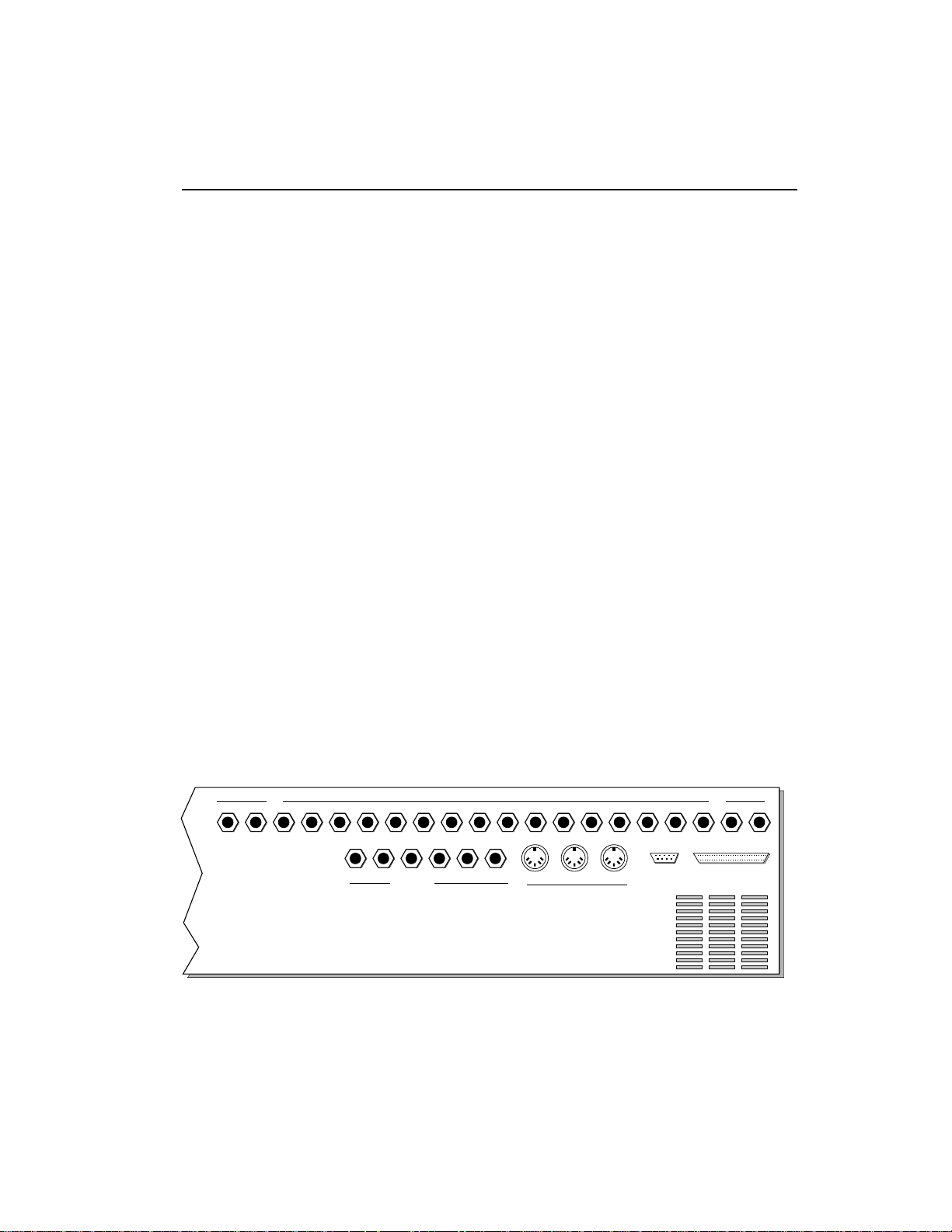
EIII CONNECTION INSTRUCTIONS
ConnectingTo a Mixer
■ Stereo: The Emulator III has provisions for a variety of output
connection schemes. The most common hookup will probably be for
stereo operation. Stereo operation allows the use of the EIII’s panning features and adds another dimension to the sound. Connect the
left and right audio out phone jacks to the inputs of your mixer or
stereo preamp. The EIII will also drive stereo headphones, which can
be plugged directly into the left/stereo output.
■ Mono: If a monophonic amplifier is used, connect the right/mono
output to the input of the amplifier. The output level of the EIII is
somewhere between instrument and line level. Care should be taken
when connecting to an instrument amplifier so that delicate nerve
cells in your ears are not damaged.
■ Individual Outputs: There may be times when different equaliza-
tion or reverb settings are desired on the various instruments that
have been sampled. The EIII has sixteen channel outputs that can be
used when individual processing on specific instruments is desired.
Inserting a plug into an output channel jack removes that channel
from the stereo mix. Zones can be assigned to output channels.
Output impedance is 470 Ω.
General Instructions
1-5
Sample In Connection
The sample input jacks can accept any signal level from microphone
level to line level. The gain is adjusted with the data slider while in
VU/gain mode in the sample module. The levels can be read in the
display while in this mode. Input impedance is 10K Ω. If you need to
preamplify the signal being sampled, set the sample gain to 00 dB
(which is one third of the way up) and use an external, high-quality
mic preamp to increase the signal level going into the EIII.
MIDI Connection
The Emulator III provides a MIDI IN, a MIDI OUT, and a MIDI
THRU port.
■ The MIDI IN port on the EIII is connected to the MIDI OUT port
of an external MIDI controller which could be a keyboard, a sequencer, MIDI drum kit or whatever. Note that the EIII can only
respond to information that your controller transmits. If your MIDI
keyboard does not have velocity and pressure sensitivity, the EIII
will not respond to velocity and pressure.
Page 14

1-6
■ MIDI OUT can be connected to another MIDI instrument or
sequencer. In MIDI OUT mode, only information from the EIII’s
keyboard, sequencer or realtime controls will be transmitted, except
when overflow mode is selected. Overflow mode allows a second
EIII to be connected to the MIDI OUT to allow 32 channel operation.
See Preset Definition, 6. MIDI for more details.
■ MIDI THRU simply retransmits any information that is received
at the MIDI IN port. Use cords that have been designed specifically
for MIDI. While regular 5 pin DIN cords may work, they are not
shielded correctly for MIDI use and may cause ground loops between equipment.
Footswitch and Pedal Connection
■ Two control footswitch jacks are provided for performance control of sequencer, arpeggiator, sustain, Xswitch, and preset increment/decrement. The footswitches need not be connected for the
unit to operate but they offer exciting control possibilities.
Footswitches should be of the momentary-contact type but can be
either normally-open or normally-closed.
■ The control pedal is used as a realtime control in the same manner
as the wheels. It can be programmably routed to a destination by
using the realtime control section of the Preset Definition module.
The pedal should be a voltage type (which varies 0-10 volts on the
tip of the jack).
SMPTE In and SMPTE Out Connection
■ The SMPTE (clock) In jack allows the Emulator III's sequencer to
read SMPTE time code at any of the four standard frame rates (24, 25,
30, 30 df). It also allows an external non-MIDI device such as a drum
machine or sequencer to control the tempo of the sequencer or
arpeggiator. The Emulator III can receive input clock rates of 24, 48,
or 96 pulses-per-quarter-note. The pulses should be at least one
millisecond wide and have a level of one to five volts.
■ The SMPTE Out jack allows the Emulator III to generate industry
standard SMPTE time code at any of the four frame rates (24, 25, 30,
30df).
RS-422 Connection
The RS-422 connector is a high-speed serial communication port
which allows data to be transferred to and from an external computer at a very high rate (500K baud). The connection cable to the
external computer will generally be supplied with a software package that you purchase.
Page 15
SCSI
The SCSI connector is a high-speed parallel interface which is
normally used to interface the EIII with external mass storage
devices such as hard disks, optical discs, or WORM drives. The SCSI
port can also be used to link the EIII with an external computer for
extremely fast file transfers. When connecting multiple external
devices to the SCSI port, the external devices should be powered up
before the Emulator Three. For more information on installation, see
Master module, 7. Disk Utilities, 1. Mount Drive, or the manual that
accompanies the external device.
110V/220 V Selector
The 110V/220V selector allows the Emulator III to be used in either
110 volt or 220 volt environments at either 50 Hz or 60 Hz. In the USA,
110 volts is the standard. To change the voltage setting, first UNPLUG the unit; then use a flat blade screwdriver to change the
setting. WARNING: Operating EIII at the wrong setting will seriously
damage the unit.
AC Power Connection and Fuse
The AC power connector is how the Emulator III gets power. The
fuse receptacle is not as obvious. It is located directly over the power
receptacle. Before changing or checking a fuse, UNPLUG the power
cord. To remove the fuse holder, squeeze the two tabs located on
either side of the fuse holder together. The fuse holder will now pop
out with its two fuses. The Emulator III uses two 2-amp, 250 volt fastblo mini-fuses. The EIII should not normally blow fuses. If a fuse that
has been replaced blows again, do not attempt another replacement.
Have the unit serviced!
1-7
SAMPLE
In Out
SMPTE
Met
OUTPUTS
2 Pedal
1
FOOTSWITCH
MIDI
MIX
16
LR
SCSIRS 422ThruOutIn
13121110987654321RL
1514
Page 16
1-8
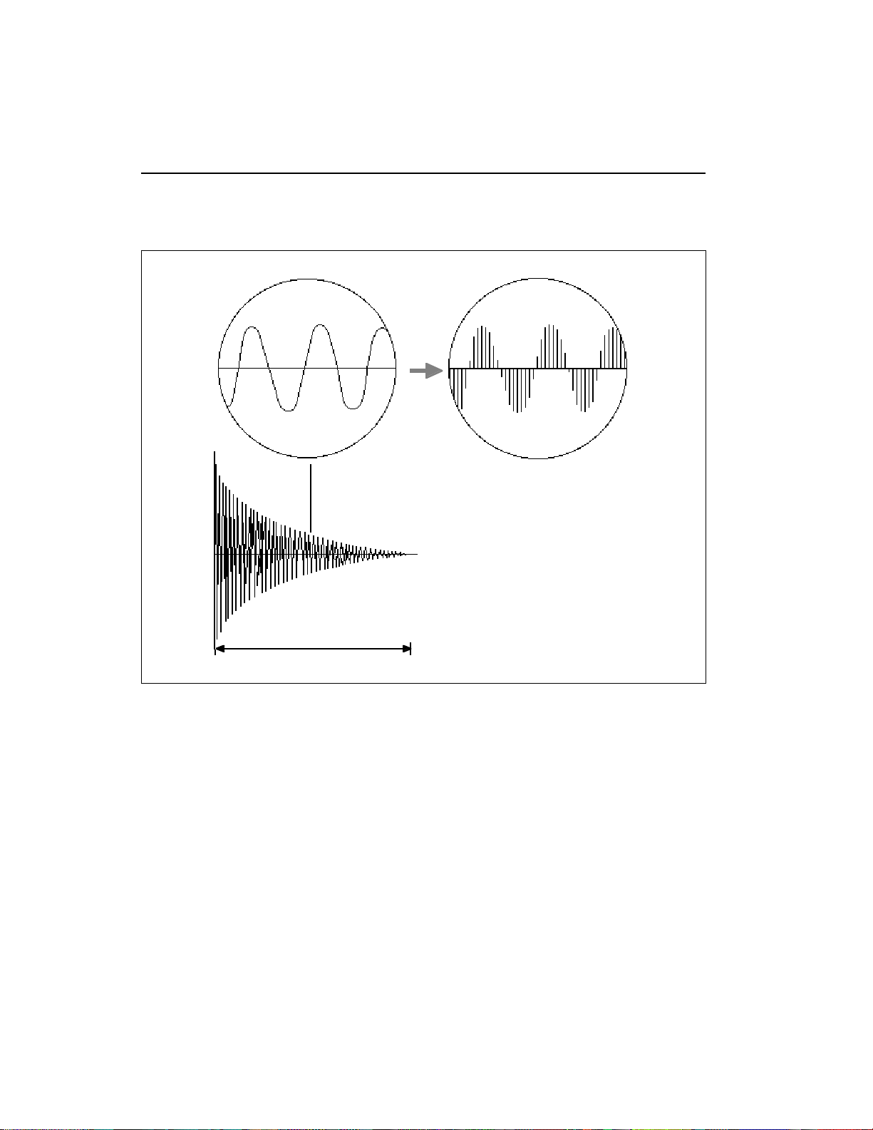
Sampling Basics
SAMPLING BASICS
Each vertical line represents a sample.
Each sample takes a "snapshot" of the
instantaneous signal level.
Percussive Sample
1 second
DIGITAL SAMPLING. Each vertical line represents a sample. Each sample takes a snapshot of the instantaneous
signal level.
Throughout this manual we will use the terms and concepts described and defined below. Read through this section carefully, even
if you don’t retain it all. You can refer back periodically as you read
through the manual until you understand the basics and definitions.
The Emulator III is conceptually like a tape recorder in that it records
sound. However, the recording process is very different since the
EIII digitally records into its computer memory.
Computers can accept information only in the form of numbers, so
first the EIII converts audio signals into numbers. It does this by
examining (sampling) the incoming signal level at your choice of
either 44,100 times a second (for maximum fidelity) or 33,100 times
Page 17

a second (to use less memory), and sequentially records these
different levels in memory. Once stored in the EIII’s memory bank,
these samples may be played back (in the proper sequence, of
course) to reconstruct the original signal. For instance, if a twosecond sound was being sampled at the highest sampling rate, it
would require (2 X 44,100) or 88,200 samples to be recorded. As you
might imagine, shorter sounds require fewer samples.
Just like tape, a sound can be manipulated once it has been recorded.
Playing back the samples in reverse order from which they were
stored plays the sound backwards. Playing back the samples at a
faster rate than the rate at which they were stored raises the pitch.
Playing back at a slower rate lowers the pitch, much like a tape
recorder’s variable speed control.
How the Emulator III Organizes Sounds
Sure, you’re anxious to start coaxing wonderful sounds from the
instrument—but the following is a necessary part of learning how to
play the Emulator III. It is important to understand how the EIII
organizes sounds in order to make best use of the instrument in the
shortest possible time. Many terms will be introduced now that
show up later in the manual.
You can think of the EIII as resembling a collection of soundorganizing modules, all contained within an EIII bank. Pathways
indicate how information flows within the EIII. Let’s take a closer
look at what makes up this information, and how it is transferred
from one section of the instrument to another. We’ll start with
individual samples, then work our way through the system.
1-9
The Sample
Sampling any sound in mono or stereo using the Emulator III’s
recording capabilities creates a sample, the raw material with which
the EIII works. The total available sampling time can be divided up
any way you like—one long sample, lots of short samples, a few
medium samples, or any combination thereof.
The term sample commonly means two different things:
1) A digital recording of a complete sound, or
2) each snapshot of the sound that makes up the complete sample.
Confusing? You bet! In this manual, we’ll assume sample means the
complete recorded sound unless indicated otherwise.
You can modify a raw sample in several ways:
■ Transposition: A sample can be transposed up or down in pitch to
cover a particular range of the keyboard. By doing this, it is not
necessary to record a sample for every key.
■ Digital Processing: Digital processing includes Looping a sample
■
Since wide-range transposition alters the sample’s timbre,
it is often necessary to use
multiple samples and transpose each one over a small
range to give the most realistic
sound. This is particularly true
with acoustic instruments.
Page 18

1-10
DEFINITIONS
(allowing even short samples to play indefinitely), Truncating (cutting off unneeded parts of the sound, thus saving memory), and
many Special Effects, to name but a few. These functions are very
sophisticated and are described later in full.
■ Analog Processing: Just as a standard analog synthesizer includes
signal processors (filter, voltage-controlled amplifier, envelope generators, LFO, and so on) to modify the sounds produced by the
synth’s oscillators, the Emulator III includes similar modules for
modifying raw samples or combinations of samples.
The Zone
A particular range of the keyboard is called a zone. This can include
one or more samples. The zone’s boundaries need not be the same as
the boundaries of the samples contained in the zone. For example, if
one sample covers the range from C1 to Bb1, and a second sample
covers the range from C2 to C3, the zone could cover C1 to C3; but
F1 to F2, G1 to A2, and so on are also equally acceptable zones.
A zone can be sent to the Analog and Digital Processing modules.
The samples (or portions thereof) included in the zone will then be
processed as specified in the Analog and Digital Processing module
functions.
Every key potentially has two zones (primary and secondary) assigned to it. If a zone is selected which includes previously defined
zones, only the parameters that are altered in the new zone will be
altered in the previously defined zones. All other parameters will
remain as previously specified.
The Preset
As mentioned above, a sample can be assigned to a single note on the
keyboard, or transposed polyphonically to cover a wider keyboard
range. The process of assigning, and optionally transposing,
samples to specific ranges of the keyboard is called making a preset.
Making a preset is a three-step process:
1. Create the preset and give it a number and name.
hold up to 100 Presets (00-99).
2. Place samples to different keyboard ranges.
five samples you could assign each sample to cover one octave of the
The bank can
For example, with
Page 19
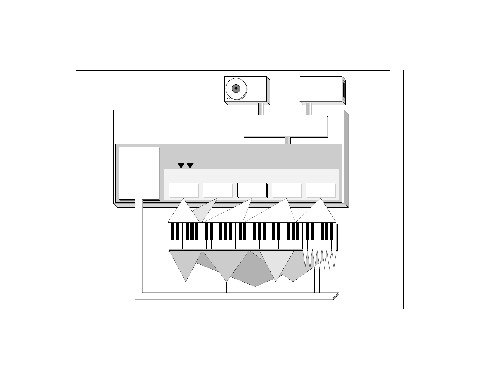
Mic or Line
Inputs
Hard
Disk
Floppy
Disk
Drive
EIII BANK
Analog
Processing
Module
Zones can be
applied to any
area of the
keyboard
Central Computer
and Master Control
Preset Definition Module
Sample and Digital Processing Modules
Sample
01
Pri Pri Pri Pri
Filt.
Cutoff
Sample
02
Sec
LFO->VCA Arpeg.
ANALOG PROCESSING ZONES
Sample
03
Vel/Level
Sample
04
Pan
Sample
99
Tun i ng
1-11Block Diagram
Page 20

1-12
keyboard. A sample can be assigned more than once within a given
preset, and assigned to more than one preset.
3. Choose from a number of the available options that further
define the preset
tially or fully overlap other samples, thus producing doubling
effects, or assigning dynamic control to individual samples in a
preset. You can modify zone parameters, add arpeggiation, and set
up MIDI and analog processing parameters.
. Some examples are: assigning samples to par-
The Bank
The memory bank contains samples, presets, and sequence data.
Everything. Consider the bank as the central storehouse for all of the
Emulator III’s data. Although the memory is volatile, meaning that
the data disappears when you turn off power, all bank data can be
saved permanently to either the floppy disk or hard disk drive
(described below) to keep a record of your work.
The Internal Drives
A disk drive is a mass-storage memory device that stores banks. The
Emulator III has two built-in drives, the floppy drive and hard drive.
However, other types of drives, as described below, can connect to
the EIII and provide additional storage.
■ Floppy Disk Drive (Drive 0): The floppy disk drive accommodates
3.5", double-sided, double-density (DSDD) floppy disks. The floppy
drive has four major applications:
■ Saving Bank Data: The EIII’s volatile bank memory can be
saved to floppy disk for more permanent storage. Since the
bank memory may exceed the capacity of the floppy disk,
it may be necessary to save to more than one disk.
■ Backing up the Hard Disk: The hard disk data can be backed
up to floppy disks. If the hard disk is full, it is necessary to
save a lot of data—you’ll need about 40 floppy disks to do
the job. The EIII has a special backup routine that guides
you through the backup process.
■ Restoring the Hard Disk: If for some reason the hard disk
fails, you can take your backup floppies and re-construct
the hard disk data. As with backing up, the EIII has a special
routine that guides you through the restoration process.
■ Distributing New Software: When the E-mu wizards come
up with exciting new enhancements, the new software is
usually distributed on floppy disk. As described later in the
manual, this software can be copied on to the hard disk and
made a permanent part of the EIII.
■ Hard Disk Drive (Drive 1): Floppy disks have been used for years
Page 21

as a mass memory storage unit for samplers. However, a hard disk
provides the advantages of much higher memory capacity (over 40
times that of a floppy disk) and far faster access time. In most cases,
you can treat the hard disk like a super-floppy. Transferring data to
and from the EIII is quite straightforward. However, you cannot
remove a hard disk and replace it with another one—the disk is a
permanent part of the drive. There are three main cautions involved
with hard disks:
■ Hard disks are sensitive to extreme mechanical shocks. If
your EIII falls off a keyboard stand, chances are the hard
disk will be damaged.
■ Make sure power is not interrupted when you write data
to the hard disk.
■ Hard disks have reached a very high level of reliability.
However, they can fail from time to time (as can any part of
a computer), so any data should be backed up periodically
and regularly on some other medium.
External Drives 2-7 (User Assigned Systems)
The EIII includes a SCSI (Small Computer Systems Interface) connector on the rear panel. This interface is commonly used in the
computer industry, so many devices made to work with computers—particularly mass storage devices—will also work with the EIII.
Here are some of the types of mass storage devices that can now, or
will soon be able to plug into the EIII’s SCSI connector.
■ CD-ROM Drive: A CD-ROM is a playback-only (data cannot be
written to it) mass storage memory device whose capacity is approximately 16 times greater than the Emulator III’s internal hard
disk (660 Megabytes instead of 40 Megabytes). Companies such as
Optical Media International produce CD-ROM disks that hold a
variety of high-quality digitized samples and sound effects. These
can be loaded into the bank as easily as you would load from a floppy
or hard disk.
■ WORM Drive: WORM stands for “Write Once, Read Many.” This
is like a CD-ROM, however, you get one shot at writing data to it,
after which that data is permanently stored in the WORM drive.
After writing, the WORM drive becomes a read-only device.
■ External Hard Disk Drives: If more memory is required, addi-
tional hard disk drives can connect to the SCSI port.
1-13
Page 22

1-14
ADDITIONAL DEFINITIONS
The Primary and Secondary Sample
An Emulator III key provides for two channels. These contain the
primary and secondary samples. For example, the primary sample
might be a guitar note and the secondary sample a detuned version
of the same guitar note. When played together, you hear chorusing.
Also, a preset contains information about how the keyboard dynamics affect the primary and secondary samples. As an example, the
primary sample could be that of a drum hit played softly, and the
secondary of a drum hit played loudly. Thus, playing the keyboard
softly would play the primary sample, and playing the keyboard
more forcefully would play the secondary sample.
The Current Preset
When you load a bank, a preset will be ready to play and the display
will show the preset number. This is the current preset. If you select
another preset, or create a preset, that will become the current preset.
■
If a module is already active,
and you are finished with one
submodule, you do not need to
re-activate the module—just
key in the new submodule
number.
The Current Sample
When recording a sample, you will need to specify the sample
number and name into which the sound should be recorded. This is
called the current sample.
Modules
A module controls a particular set of functions in the Emulator III.
There are six main modules : Master, Preset Management, Preset
Definition, Sample, Digital Processing, and Analog Processing.
The sequencer is made up of: Management, Setup, Edit, and Mode.
The large module to the left of the sequencer is the Control Panel.
This provides several controls, many of which are designed to select
options when working with the main or sequencer modules.
■ Activating a Module and the Module Identifier: To work with a
module, you must first activate it. Press the button associated with
the desired module. The display will then show the Module Identifier and invite you to select a submodule.
■ Submodule: Each module contains several numbered submodules
that set controls for additional functions. There are two ways to
select a submodule within the module. You can move the data slider
until the display shows the desired submodule, then press ENTER.
As you work with the EIII, though, you will start to memorize the
submodule numbers and will probably find it faster to simply key in
the appropriate submodule number using the numeric keypad.
Page 23

When using the keypad, it is not necessary to press ENTER. Pressing
the module button will cancel the operation.
Velocity-Sensitive Keyboard
A velocity-sensitive keyboard measures how long it takes for a key
to go from the key up to key down position, and uses this data to
control dynamics. If it takes a long time for the key to reach the key
down position, it is assumed you are playing that key less forcefully
(minimum dynamics). If the key goes to the key down position
almost instantaneously, it is assumed that you are playing the key
more forcefully (maximum dynamics). In this manual, we will refer
to playing the keyboard harder or softer, even though technically
speaking the keyboard is reacting to speed of key position change,
not force.
Pressure-Sensitive Keyboard
A pressure-sensitive (also called aftertouch) keyboard responds to
the pressure applied to a key after it is down. This pressure data
typically controls vibrato amount, pitch-bending, volume, and/or
other elements that add expressiveness to a part.
Saving
The bank only retains data for as long as the Emulator III is plugged
in and turned on. Of course, we don’t expect you to leave the thing
on all the time, which brings us to the subject of saving data.
Pressing the SAVE BANK button on the Control Panel shuttles all
the bank data (samples, presets, and sequences) to the drive of your
choice (usually the internal hard disk). The hard disk permanently
stores data (well, at least as long as the disk lasts) so that even after
turning off the Emulator III, the disk will contain a record of your
work. Data can also be saved to floppy disks.
IF YOU DO NOT SAVE A BANK, ALL BANK DATA WILL BE LOST
WHEN YOU TURN OFF THE MACHINE . Do not wait until the end
of a session to save. Save your work periodically in case of power
failure or some other unforeseen circumstance that might erase the
bank’s memory. Hard disks are not infallible. All hard disk banks
should be backed up periodically on floppy disk. Should you improve the preset, sample, or sequence later, you can always replace
the original with the revised version. And if something goes wrong,
the original will still be available to save you the ordeal of starting
from scratch. Individual presets, and the samples they contain, can
also be saved to disk. Whenever you have done enough work on a
preset, sample, or sequence that you would hate to lose it, back it up!
Since the disk (hard or floppy) contains a record of the bank data,
1-15
Page 24

1-16
loading the disk back into the bank transfers all the sample, preset,
and sequencer data into the bank. This will replace the existing bank
data, if any.
The Channel Outputs
The Emulator III assigns the sounds you play to the various output
channels. For example, when you play a key, that key’s sound is
assigned to output channel one. If you hold this key and play another
key, the new key’s sound will be assigned to output channel two. The
EIII includes sixteen channels. You can play up to sixteen sounds
simultaneously. Each channel has its own output jack, and there are
also stereo output jacks (use one for mono) that mix the sixteen
channels together.
You can change the channel assignments.This process is described
in Analog Processing, 9. Output Channels.
Booting
Booting is a computer term that means “having the computer read
the software necessary for its operation from the disk.” (It’s easy to
see why this was shortened to booting.) The EIII automatically boots
itself from the hard disk when you turn it on. Once booted, the
instrument is ready to go. If the hard disk is damaged for some
reason, the EIII can be booted from a suitable floppy disk.
Default
A default setting is what we’ve judged to be a useful initial setting,
and remains in effect until you change it. For example, if you create
a new preset, the arpeggiator will default to Off. Had it defaulted to
the on position, all new presets would be arpeggiated.
The Cursor
The cursor is that small flashing line on the display. It sits under the
number or letter that will be altered if you enter data. Entering a new
value will overwrite the number or letter above the cursor, whereupon the cursor will move on to the next number or letter (if
applicable). If the EIII is expecting a two or three-digit number, in
most cases you must enter all the required digits even if some of these
are zeroes (called leading zeroes). For example, if the EIII is expecting a three-digit number and you want to enter 8, you would enter
008. If it is expecting a single-digit number, entering 8 would be
sufficient.
Data Slider & Increment/Decrement Buttons
In virtually all instances where the data slider selects options, the
Increment +/YES/ON and Decrement -/NO/OFF switches duplicate the slider. Press +/YES/ON to increase a value, or -/NO/OFF
Page 25

to decrease.
Selecting
When the instructions say to select an option, you can use whatever
method is most comfortable for you: the data slider, the Increment/
Decrement buttons, the numeric keypad (if applicable) and, when
naming, the keyboard keys. Some functions do not implement all
these options; you can’t go wrong by trying, though. If a function
doesn’t respond to the numeric keypad, for instance, then pressing
the keypad will have no effect. Use the data slider or the Inc/Dec
buttons instead.
The Big Re-Cap
One more time: A sample is a raw sound that is recorded into the
bank. The sample can be processed or otherwise modified.
To create a new preset, make sure you have all the samples required
for the preset in the bank, number and name a preset, then assign
combinations of samples from the bank to specific sections of the
keyboard. By specifying one or more of these samples (or portions
thereof) as a zone, the zone may then be processed by the EIII’s
analog and digital signal processors.
After arranging a bank , it can be saved to one or more drives. Usually
this will be the internal hard drive or floppy drive.
Since loading from a floppy or hard disk fills the bank with samples
and presets, you can group these samples into new presets, process
the samples contained in particular zones, or alter existing presets.
1-17
Page 26
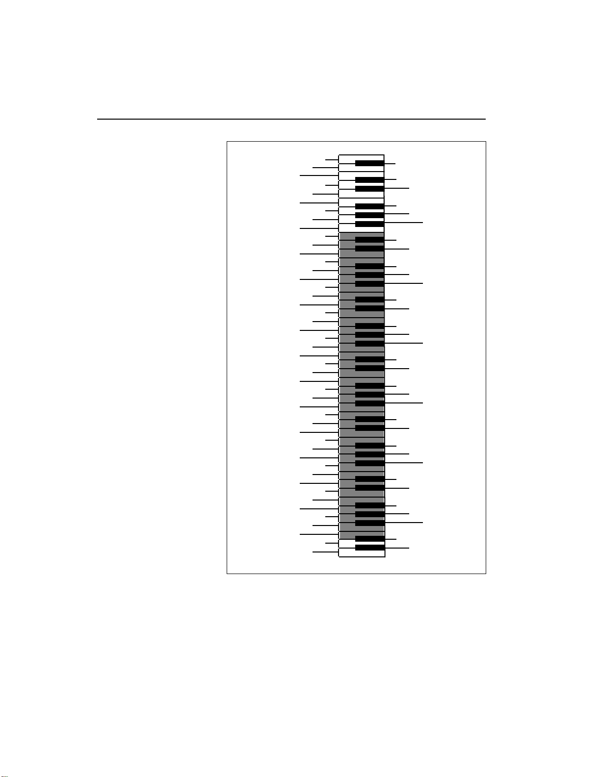
1-18 Keyboard Characters
■
The shaded area represents
the five octave keyboard on
the Emulator III.
M
W
0
2
3
5
7
8
:
<
>
?
A
C
D
F
H
J
K
O
P
R
T
V
Y
[
¥
^
`
b
c
e
g
h
j
l
n
o
q
s
t
v
x
z
{
}
<-
1
4
6
9
;
=
@
B
E
G
I
L
N
Q
S
U
X
Z
]
_
a
d
f
i
k
m
p
r
u
w
y
|
->
Page 27
C C# D D# E F F# G G# A A# B Pitch
1-19Available Characters
-1
0
1
2
3
4
5
6
blank
'()*+,-./012
3456789: ;< >=
?@ABCDEFGH I J
KLMNOPQRSTUV
WXYZ[¥]^_`ab
cdefghijklmn
opqrstuvwxyz
{|}
"!#$%&
Octave
No.
AVAILABLE CHARACTERS. Banks, drives, samples, presets, segments, and songs can be named or renamed
using these characters. Select the characters using the ten key pad, data slider, and keyboard. You can also use
the up cursor to insert spaces and the down cursor to delete spaces. Shaded characters are only available using
the data slider.
Page 28

1-20
Page 29

3-MASTER
1. MASTER TUNE 3-2
2. RENAME BANK 3-3
3. ERASE BANK 3-4
4. SUPERMODE 3-5
5. AUDIO TRIGGER 3-7
6. MEMORY 3-9
AVAILABLE
7. DISK UTILITIES 3-10
0. Change SCSI ID# 3-11
1. Mount Drives 3-11
2. Rename Drive 3-12
3. Erase Disk Bank 3-12
4. Copy Software 3-13
5. Lock Bank and Drive 3-14
6. Disk Status 3-15
7. Format Disk 3-16
8. Backup and Restore 3-17
9. Erase Software 3-20
8. SPECIAL 3-22
1. Audition Key 3-23
2. Disable Outputs 3-23
3. Recalibrate 3-24
4. Footswitch Polarity 3-25
5. Dynamic Allocation 3-26
6. Software Version 3-26
7. MIDI Globals 3-27
8. Volume Pedal Global 3-28
9. MIDI Load Bank 3-29
Page 30

3-2
Master Tune
1. MASTER TUNE
Master Tune adjusts the tuning of all the samples in the current
bank, so that you can tune the Emulator III to other instruments.
1. Activate Master module.
2. Select Submodule 1.
3. Select the desired tuning offset.
semitone below concert pitch) to +100 (one semitone above concert
pitch).
This is variable from -100 (one
MASTER TUNE
Offset: + 0.0 cents
Select Tuning Offset
4. Press ENTER to exit the submodule.
Module Identifier.
The EIII will return to the
Page 31

2. RENAME BANK
This submodule allows you to rename any bank.
1. Activate Master module.
2. Select Submodule 2.
3. Rename the bank.
left and right cursor buttons. Select the desired characters by using
the ten key pad, data slider and keyboard. You can also use the up
cursor to insert spaces and the down cursor to delete spaces.
B01 Current Bank
[0-9]/Slider/Keyboard
Choose the characters to be changed with the
RENAME BANK
Rename Bank
■
Use the data slider to access
the full character set. The keyboard does not have enough
keys to access all available
characters.
3-3
4. Press ENTER to exit the submodule.
Module Identifier
The EIII will return to the
Page 32

3-4
Erase Bank
3. ERASE BANK
Erasing a bank erases ALL the memory in the Emulator III, which
includes all samples, presets, and sequences.
1. Activate Master module.
2. Select Submodule 3.
■
After erasing the bank, the
EIII will automatically create
an empty preset for you.
3. Decide if you really want to erase the bank.
inform you that you are about to erase all samples, presets, and
sequences in the current bank.
The display will
ERASE BANK
Erases All Presets,
Samples & Sequences!
Are You Sure? Y/N
4. Press Yes to erase the bank or No to cancel the operation.
either case, the EIII will return to the Module Identifier.
In
Page 33

Supermode is a wonderful MIDI function that maps data occurring
on a specific MIDI channel to a specific preset within the bank. This
is similar to MIDI’s standard Omni Off/Mono mode but much more
flexible, since each channel will not only be directed to its own preset,
but can contain polyphonic note data as well. Supermode allows up
to 16 individual presets to be addressed and play simultaneously
over MIDI.
When used in conjunction with Supermode, the internal sequencer
built into the EIII is capable of simultaneously recording data received on multiple MIDI channels and routing the data received on
each individual MIDI channel to a separate sequencer track. For
more information, refer to the Sequencer section.
1. Activate Master module.
2. Select Submodule 4.
3-5Supermode
4. SUPERMODE
■
Enable Supermode by
pressing the Supermode button located in the Controls
section.
3. Select a MIDI channel.
the EIII displays the currently mapped preset on line three.
As you scroll through the MIDI channels,
SUPERMODE
MIDI Channel: 01
P00 Mapped Preset
Select a Channel
4. Move the cursor to line three and select a preset.
default to the first non-empty preset, if the previous mapped preset
was empty.
The EIII will
SUPERMODE
MIDI Channel: 01
P01 Current Preset
Select a Preset
5. Move the cursor to line two and repeat steps 3 and 4 to map
additional MIDI channels.
■
Even in Supermode, the total number of voices sounding
on all channels cannot exceed
16.
■
Only one set of Supermode
preset assignment parameters can be stored in each
bank.
Page 34

3-6
SUPERMODE
MIDI Channel 1
MIDI Channel 2
MIDI Channel 3
MIDI Channel 15
MIDI Channel 16
Preset 20
Preset 01
Preset 12
Preset 02
Preset 10
MIDI
IN
Supermode
6. Press ENTER to exit the submodule.
Module Identifier.
In addition, Supermode preset assignments can be changed in
realtime over MIDI. For preset changes to occur, Supermode must be
enabled by pressing the Supermode button. (Its associated LED will
light, and remain lit until Supermode is disabled.)
Also, you must set preset change parameters to On for the current
preset in the Preset Definition module, 6. MIDI, as shown on line
three of that window:
The EIII will return to the
MIDI
Send Preset Chg: on
Recv Preset Chg: on
Send Start/Stop: on
■ To Execute a Supermode Preset Change Over MIDI:
1. Send the preset change command on the MIDI channel that
the desired change is to occur upon.
Page 35

5. AUDIO TRIGGER
The Audio Trigger function allows the Emulator III to be triggered
from an audio source or directly from electronic drum pads. Applications include replacing sounds recorded on tape with sampled
sounds, using the EIII as a fast, 16-bit drum set with two pads, or
perhaps as a high-fidelity, sonically triggered burglar alarm.
In the Audio Trigger mode, the sample inputs function as the trigger
inputs. Standard (Simmons-type) electronic drum pads work well as
trigger sources, as do acoustic drums recorded on tape. Use the
sample input slider to adjust the level. A microphone serves well to
help learn the operation of the various functions.
1. Activate Master module.
Audio Trigger
■
Audio Trigger assignments
and parameters are stored for
each individual bank. They
also affect the current preset.
3-7
2. Select Submodule 5.
the following parameters:
There are two pages. The first page shows
AUDIO TRIGGER:Both
Threshold: |
Left: Off |
Right: C#1 |||||||||
3. Select page two by pressing the right cursor button.
display shows:
The
AUDIO TRIGGER
Duration: 999ms
Capture Time: 20ms
Recovery Time: 5ms
4. Use the cursor buttons to select one of the following
parameters to edit:
■ Audio Trigger: Allows you to select whether you are viewing and
editing the trigger parameters for the left, right, or both channels.
■ Threshold: This is the level at which a sound is triggered. The
trigger threshold should be set at a point high enough so that the
background noise does not trigger the sound and low enough so that
___________________________
Page 36

3-8
Audio Trigger
Noise
Floor
Capture
Time
Trigger Threshold
Percussion Transient
Recovery
Time
Note Duration
AUDIO TRIGGER FUNCTIONS. This chart displays trigger threshold, capture and recovery times and the note
duration of a percussion transient.
■
Experiment with the Gate/
Trigger Keyboard modes
(Analog Processing, 7. Keyboard Mode) and/or the VCA
Envelope generator (Analog
Processing, 2.VCA) for best
triggering results, and also for
special effects.
the sound will trigger accurately. It should be noted that the trigger
threshold “rides” the noise floor. The EIII constantly measures the
noise floor and keeps track of the minimum value. The minimum
value is reset after every trigger.
■ Left: This allows you to set the keyboard note to be triggered by the
left input. The VU meter shows the relative input level as controlled
by the sample input slider.
■ Right: This allows you to set the keyboard note to be triggered by
the right input. The VU meter shows the relative input level as
controlled by the sample input slider.
■ Duration: The note duration is the time between note on and note
off. If you were playing the keyboard, this would be the amount of
time that you held the note. This also affects the MIDI OUT note
duration. Re-triggering the input will cause an immediate note off to
occur.
■ Capture Time: This is the amount of time that the EIII will analyze
■
When a sound is re-triggered using the Audio Trigger
function, each new trigger will
cause the sound to be played
on a new output channel. This
may cause the sounds to overlap and may not always be
desirable. To re-trigger the
same channel, assign the selected key to only one output
channel in Analog Processing,
9. Output Channels.
the trigger input signal to determine the maximum level that is used
to determine velocity.This should be kept at a minimum to avoid
unnecessary delay. Since this function does delay the trigger, it
should be set to 0ms if velocity is not being routed to any analog
parameters as set in Analog Processing, 6.Velocity To.
■ Recovery Time: This is the time period which must elapse before
the EIII will allow re-triggering of the sound.
5. Press ENTER to exit the submodule.
The EIII will return to the
Module Identifier.
Page 37

6. MEMORY AVAILABLE
Memory Available shows how much of each type of memory is
available, both as a percentage of available memory and as memory
units. For example, if you have used up 90.0% of the available preset
memory, the display will show that there is 10.0% preset memory
remaining. This is equivalent to 5,555 memory units.
MEMORY AVAILABLE (EMPTY BANK)
Preset Sample Sequence
4 Mbyte
8 Mbyte
1. Activate Master module.
2. Select Submodule 6.
55,554 2,092,032 523,008
55,554 4,189,184 1,047,296
Memory Available
3-9
3. Observe the display.
of preset memory available. Line three shows the percentage and
amount of sample memory available. Line four shows the number of
sequencer events available.
Line two shows the percentage and amount
MEMORY AVAILABLE
Preset: 99.7% 55512
Sample: 100% 2092032
Seq Events: 523008
4. Press ENTER to exit the submodule.
Module Identifier.
The EIII will return to the
■
The EIII uses the same
block of memory for samples
as it does for sequences. Creating samples will eat up sequence events and vice versa.
The ratio is four sample words
for each sequence event.
Page 38

3-10
Disk Utilities
7. DISK UTILITIES
Disk Utilities include several additional numbered sub-sections.
Here are brief descriptions of each sub-section. More extensive
descriptions follow.
■ 0. EIII SCSI ID#: Allows you to change the EIII's SCSI ID number.
■ 1. Mount Drives: Instructs the Emulator III to check the SCSI bus
for the presence of SCSI devices.
■ 2. Rename Drive: Changes the name of a particular drive.
■ 3. Erase Disk Bank: Erases a bank from any of the available hard
drives.
■ 4. Copy Software: Allows you to update and make new copies of
the operating software supplied on a floppy disk by E-mu Systems
or your authorized dealer.
■ 5. Lock Bank and Drive: Prevents a specific bank and/or drive
from being overwritten.
■ 6. Disk Status: For a hard disk drive, this function displays the
amount of space that is available, and if the drive is locked or not. For
floppy disks this function indicates if it is a software disk, the name
and number of a bank disk, and if the disk is blank.
■ 7. Format Disk: Initializes a floppy disk, or the hard drive, to store
Emulator III data.
■ 8. Backup and Restore: Although E-mu has taken every precau-
tion to ensure reliable components, hard disk drives can fail from
time to time. This function allows you to backup the hard disk
contents on to multiple floppy disks, and if necessary, re-construct
■
All external SCSI devices
should be turned on before the
Emulator Three.
the hard disk from the data on those floppies.
■ 9. Erase Software: Erases the operating software from any of the
available hard disk drives.
■ To Access Any of the Disk Utilities:
1. Activate Master module.
2. Select Submodule 7.
3. Select the desired disk utility within Submodule 7.
Page 39

■
0. CHANGE SCSI ID#
This utility allows you to change the SCSI ID number of the EIII (not
it's internal hard disk) or the HD300 in the event that they conflict
with a device on the SCSI bus having the same ID number.
The SCSI interface, located as a 25-pin connector on the back panel,
allows the EIII to communicate with external storage devices. The
EIII can support seven SCSI devices (including it's internal HD).
Each device on the SCSI bus has it’s own ID number so that it can
distinguish its data from data meant for other SCSI devices. If a SCSI
device is added to your system which has the same ID number as an
existing device, a SCSI error would occur. To remedy this situation,
the ID number on the new device will have to be changed. Consult
the operation manual of the external device for information on
changing the SCSI ID number.
1. Activate Master module.
2. Select 7. Disk Utilities, 0. Change SCSI ID# (7/0).
3. Select a SCSI Device (either the EIII or the HD300).
4. Select the new SCSI ID number.
3-11Disk Utilities
CHANGE SCSI ID#
Device Type: EIII
5. Press ENTER to exit the submodule.
choice to the System and return to the Module Identifier.
■
1. Mount Drives
This utility instructs the EIII to check the SCSI bus for the presence
of SCSI devices.
If a SCSI device has been powered up after the Emulator III, it will not
appear in the list of available devices. The Mount Drives utility tells
the EIII to check the SCSI bus and to add any SCSI devices that it finds
to its list of available SCSI devices. Normally, if the external devices
are powered up before the EIII, this will be done automatically.
The EIII will save your
■
Use the "Mount Drives" utility whenever an external SCSI
device does not appear on the
list of available devices.
Page 40

3-12
Disk Utilities
1. Activate Master module.
2. Select 7. Disk Utilities, 1. Mount Drives (7/1).
3. The Emulator III will mount the drives, then return to the
Module Identifier.
■
2. Rename Drive
1. Activate Master module.
2. Select 7. Disk Utilities, 2. Rename Drive (7/2).
3. Select an installed drive, then press ENTER.
RENAME DRIVE
D01 Current Drive
Select a Drive
4. Rename the drive.
left and right cursor buttons. Select the desired characters by using
the ten key pad, data slider and keyboard. You can also use the up
cursor to insert spaces and the down cursor to delete spaces.
Choose the characters to be changed with the
RENAME DRIVE
D01 Current Drive
[0-9]/Slider/Kybd
5. Press ENTER to exit the submodule.
Module Identifier.
■
3. Erase Disk Bank
With this utility, banks can be erased from any of the available
drives.
1. Activate Master module.
The EIII will return to the
Page 41

2. Select 7. Disk Utilities, 3. Erase Bank (7/3).
3. If you wish to select a different drive, press the up cursor. If
not, proceed to step 5.
4. Select the drive containing the bank to be erased, then press
ENTER.
ERASE DISK BANK
D1 Internal HD
Select a Drive
5. Select the bank to be erased, then press ENTER.
ERASE DISK BANK
D1 Internal HD
B00 Current Bank
Select a Bank
Disk Utilities
■
The display will advise you if
you try to erase a bank or drive
that is locked. Unlock the bank
and/or drive before proceeding.
3-13
6. Decide if in fact you want to erase the selected bank.
display will ask if you’re sure.
7. Press Yes to erase the bank or No to cancel the operation.
either case, the EIII will return to the Module Identifier.
■
4. Copy Software
From time to time, E-mu engineers devise new operating system
software intended to enhance or add new features to the EIII’s
existing capabilities. This software is distributed on a floppy disk.
Software should be copied over to the hard disk so that the new
system will automatically load whenever you turn on the EIII. The
system software should be resident on only one hard disk drive in
your equipment setup. If you do not install new software on the hard
disk you will have to load it from the floppy disk each time you
power up the machine.
Each version of the operating system is numbered, and is indicated
when you select 8. Special, 6. Software Version (8/6). Copying
software on to the hard disk will not change any other data like
samples, presets, and sequences. It is a good idea to keep at least two
backup copies of the system software on floppy disk.
The
In
■
If the disk you are copying to
is an un-formatted floppy, you
will be asked if you wish to
format the disk. Press Yes to
format the floppy disk, or insert
a formatted disk and press No.
■
It is also possible to copy the
system software from the hard
disk back to a floppy, although
sounds and software cannot
coexist on a floppy.
Page 42

3-14
Disk Utilities
■
If there is not enough
sample memory left to accomodate the new software, the
display will ask if you want to
erase the bank. Press Yes to
erase the bank and continue
loading software from the
drive. Press No to cancel the
operation so that you can save
the bank first, before copying
the new software.
■
If you copied new software
to the boot drive, now is a good
time to power the Emulator III
off and on.
Hard Disk Drive
w/software
1. Activate Master module.
2. Select 7. Disk Utilities, 4. Copy Software (7/4).
3. Select the drive containing the new software and press
ENTER.
ENTER, the display will inform you that the new software is being
loaded.
Usually this will be the floppy drive. After pressing
COPY SOFTWARE from
D0 Floppy Drive
Select a Drive
4. Select the destination drive for the new software and press
ENTER.
drive. After pressing ENTER, the software will be copied and the
EIII will return to the Module Identifier.
Typically, this will be the Emulator III’s internal hard disk
COPY SOFTWARE into
D0 Floppy Drive
D1 Internal Drive
Select a Drive
N
o
C
a
l
C
a
l
After copying new software from a floppy disk to
the internal hard disk drive, it is a good idea to
save the software from the internal hard disk back
to a floppy disk.
Hard Disk Drive
No software
Floppy
Software
l
a
g
e
l
l
l
l
a
C
This process will save the EIII’s calibrations as
well as the software on the floppy disk. The calibrations include important information pertaining to the panel controls and individual channel
trims.
Page 43

■
5. Lock Bank and Drive
If you don’t want to risk curious hands unintentionally erasing a
bank or drive, here’s a safeguard. A complete drive or any bank
within that drive can be locked against inadvertent erasure or
tampering, and subsequently unlocked as needed.
1. Activate Master module.
2. Select 7. Disk Utilities, 5. Lock Bank/Drive (7/5).
3. If you want to lock a drive or change the current drive, press
the up cursor button. If not, go on to step 6.
the current drive and its lock status, whether on or off.
The display will show
LOCK DRIVE: off
D1 Current Drive
Select a Drive
4. Select the drive to be locked or unlocked, then press ENTER.
Disk Utilities
3-15
5. Select whether lock is on or off, then press ENTER.
6. Select the bank to be locked or unlocked, then press ENTER.
The display will show the current bank and its lock status, whether
on or off.
LOCK BANK: off
D1 Selected Drive
B00 Current Bank
Select a Bank
7. Select whether lock is on or off, then press ENTER.
will return to the Module Identifier.
■
6. Disk Status
This function displays the amount of space that is available on a hard
disk drive and if the drive is locked or not. For floppy disks, this
function indicates if it is a software disk, the name and number of a
bank disk, or if the disk is blank.
The EIII
■
This function will not let you
lock a floppy disk. To lock a
floppy, open the write-protect
window on the disk.
Page 44

3-16
Disk Utilities
1. Activate Master module.
2. Select 7. Disk Utilities, 6. Disk Status (7/6).
3. Select a drive, then press ENTER.
insert a disk before pressing ENTER.
If selecting the floppy drive,
DISK STATUS
D1 Internal HD
Select a Drive
4. One of the following displays will appear:
DISK STATUS
D1 Internal HD
Avail: 20.7% 8.49Mb
88 Banks Unlocked
DISK STATUS
D0 Floppy Drive
Software: v1.00
Software Floppy Disk
DISK STATUS
D0 Floppy Drive
Piano Bank
Disk 4 of 8
DISK STATUS
D0 Floppy Drive
Floppy Disk is Blank
Page 45

.
To select another disk, press ENTER and return to step 3.
5
Disk Utilities
3-17
6. Press the Master button to exit the submodule.
return to the Module Identifier.
■
7. Format Disk
Before a new floppy disk or hard disk can record or store any data,
it first must be told how to record this data. This is called formatting.
The floppy disk formatting procedure should be run on any new
disk, or on recycled disks previously used with other systems (such
as home computers), since these will not be formatted correctly for
the Emulator III.
1. Activate Master module.
2. Select 7. Disk Utilities, 7. Format Disk (7/7).
3. Select the drive to be formatted and press ENTER.
default to the floppy drive.
The EIII will
The EIII will
FORMAT DISK
D0 Floppy Drive
Select a Drive
■
Use only 3.5 inch DSDD
(double-sided, double-density) disks. Avoid bargain
disks. To save money, consider purchasing disks in large
quantities.
■
Formatting a floppy disk will
not erase the bank currently in
memory.
4. Consider the implications of your action.
or hard disk erases all information on that disk completely. The
display will inquire if in fact you want to do this.
Formatting a floppy
FORMAT DISK
D0 Floppy Drive
Are You Sure? Y/N
5. Press Yes to continue the formatting procedure or No to
cancel the operation and return to the Module Identifier.
6. If in step 3 you selected the floppy drive, insert a floppy disk,
and press ENTER.
Formatting takes about 20 seconds.
Page 46

3-18
Disk Utilities
■
The recommended type
of R/W Optical drive for the
EIII uses the Sony type
cartridge. Brand names include Sony, Pinnacle, PLI,
and Alphatronics to name a
few.
7. After formatting a floppy disk, format another, if desired.
The
display will ask if you want to format another floppy. To do this,
press Yes, remove the current disk, insert a new disk, and press
ENTER. Otherwise, press No to cancel the operation and return to
the Module Identifier.
FORMATTING HARD DISKS
This works exactly like formatting a floppy disk except when the
display asks you to "Select a Drive", you should select the hard disk
instead of the floppy. If the hard disk is not listed, use Disk Utilities
1, to Mount Drive. The hard disk drive should now be listed.
Formatting a hard drive takes about 15 to 45 minutes, depending on
the size of the HD.
R/W OPTICAL DISKS
Read/Write Optical disks are formatted in the same way as a hard
disk. Use optical disk cartidges with 512 bytes/sector rather than the
1024 byte/sector type. New optical disk cartidges usually come with
the "low level" formatting already in place. If so, the disk will format
normally. If this low level formatting has not been performed, the
EIII will interrupt the formatting process and show a "SCSI Hardware Error". If this happens, follow the procedure for Low Level
formatting on the next page, then format the disk in the normal way.
Note: Optical disks always verify the data as it is written and so do
not require the long verify process that occurs after formatting has
been completed. You can save hours of time by ejecting the cartridge
and re-booting the system after the "VERIFYING FORMAT" message appears in the EIII display (about 10 seconds).
HARD DISK INTERLEAVE
The Emulator Three contains an internal list of recognized hard disk
drives. The list contains parameter information designed to optimize the interface between the EIII and the drive. The following hard
disk drive brands are currently listed:
■ Miniscribe 2:1 interleave
■ Rodime 2:1 interleave
■ Conner 3:1 interleave
■ Seagate 3:1 interleave
■ CDC 1:1 interleave
■ Syquest 1:1 interleave
■ Qume 4:1 interleave
Other hard disk brands will probably also work. If in doubt, the best
idea is to try out the drive with the EIII before you buy it. If your
brand of hard drive is not listed but works with the EIII, you may be
able to optimize its performance even further.
8. There is a hidden menu when the display asks: "Are You
Page 47

Sure?".
Before choosing Yes or No you may choose one of the following hard
disk interleave options:
FORMAT DISK
D1 Internal HD
Are You Sure? Y/N
0--- Uses the EIII's default interleave for the type of HD.
Fast 1--- 1:1 interleave
2--- 2:1 interleave (this is the EIII's default setting)
3--- 3:1 interleave
4--- 4:1 interleave
5--- 5:1 interleave
6--- 6:1 interleave
7--- 7:1 interleave
Slow 8 --- 8:1 interleave
9--- Optical Disk Low Level Formatting
Disk Utilities
3-19
After formatting the HD, measure the time it takes to save a file to the
hard disk using the different interleaves. The fastest one wins! The
lower the interleave ratio, the faster the hard disk.
Option #9 allows you to perform a low level format on a "virgin"
optical platter (of the Sony type only). Most optical disks that you
buy will already have this low level formatting, but some don't and
will not be recognized by the EIII. This utility allow you to perform
the function. This takes about 25 minutes, so don't do it unless
absolutely necessary.
Page 48

3-20
Disk Utilities
■
8. Backup and Restore
This module allows you to backup and restore a portion or the entire
contents of the hard disk. This function makes it so easy that you
really will have no excuse for not backing up all your hard disk
banks. If you'd hate to lose it, BACK IT UP.
There are two ways to back up your sound banks:
■ To Backup to Floppy Disk:
We suggest labeling bank sets numerically. Keep your bank sets
organized, and try to backup regularly, at least once a week.
1. Activate Master module.
2. Select 7. Disk Utilities, 8. Backup & Restore (7/8).
■
Use only 3.5 inch DSDD
(double-sided, double-density) disks. Avoid bargain
disks. To save money, consider purchasing disks in large
quantities.
■
If the disk you are copying to
is an un-formatted floppy, you
will be asked if you wish to
format the disk. Press Yes to
format the floppy disk or insert
a formatted disk and then
press No.
3. Select the source drive.
contains the data you wish to backup. The display shows:
The source drive is the drive that
BACKUP/RESTORE from
D1 Internal HD
Select a Drive
4. Use the data slider to select the internal hard disk drive and
press ENTER.
BACKUP/RESTORE into
D1 Internal HD
D0 Floppy Drive
Select a Drive
5. Use the data slider to select the destination, D0 Floppy Drive,
then press ENTER.
updated banks, which are the banks that have changed since you last
backed up. Saving a bank to the hard disk constitutes a change
You now have the option to backup all banks or
Page 49

If you select all banks, then you may choose from any bank on the
hard disk. If you select updated banks, you may choose only from the
updated list.
Disk Utilities
3-21
6. Press ENTER after you have selected the Backup mode.
display will say Erases Bank! OK? Y/N. Press Yes if you want to
erase the bank, or press No to cancel the operation and return to the
Module Identifier.
The
BACKUP/RESTORE from
D1 Internal HD
D0 Floppy Drive
Bank Type: All
If you selected Yes, the display will say Select a Bank and the cursor
will flash under the lowest numbered bank.
BACKUP/RESTORE into
B01 Stereo Grand
Select a Bank
7. When you have selected a bank to be backed up, press
ENTER.
bank.
The display will prompt you to insert the first disk of the
8. Press ENTER after inserting each disk in the drive as directed
by the Emulator III.
BACKUP/RESTORE from
B01 Stereo Grand to
Floppy Drive
Insert Disk 1 of 5
Page 50

3-22
Disk Utilities
■ To Backup to an External Hard Disk:
If you have another hard disk drive, you will be able to save even
more time when backing up.
1. When the display asks you for the destination drive, select the
external hard disk drive, then press ENTER.
BACKUP/RESTORE into
D1 Internal HD
D2 External HD
Select a Drive
2. Select between Automatic or Interactive backup modes.
BACKUP/RESTORE from
D1 Internal HD to
D2 External HD
Mode: Interactive
■ Automatic Mode : transfers the complete contents of the source
hard disk (or just the updated banks) to the destination drive
without prompting you at each bank. Existing destination disk
banks will be overwritten with the like-numbered source bank files.
For example, if you have banks one, three, and five on the internal
hard disk, those same banks will be overwritten on the destination
drive. The other banks will be left untouched.
BACKUP/RESTORE into
D01 Floppy Drive
D1 Internal HD
Select a Drive
Page 51

■ Interactive Mode: transfers the complete contents of the source
hard disk drive (or just the updated banks) to the destination drive,
but prompts you to select each source and destination bank.
Disk Utilities
3-23
3. Select the backup mode and press ENTER.
inquire if you are sure. Press Yes if you are, and backup will proceed.
Press No to cancel the operation and return to the Module Identifier.
■ To Restore:
Restore works in exactly the same way as Backup. The only difference is that the source and destination drives are reversed.
■
9. Erase Software
With this function, software can be erased from any of the hard disk
drives.
1. Activate Master module.
2. Select 7. Disk Utilities, 9. Erase Software (7/9).
3. Select the drive containing the software to be erased, then
press ENTER.
The display will
ERASE SOFTWARE
D1 Internal HD
Select a Drive
4. Decide if you really want to erase the software.
erase the system, which includes all the calibration and machine
variables. The display will ask if you really want to do this.
5. Press Yes to erase the software or No to cancel the operation.
In either case, the EIII will return to the Module Identifier.
This will also
Page 52

3-24
Special
8. SPECIAL
This section contains several additional numbered functions. Here
are short descriptions of each sub-module. More extensive descriptions follow.
■ 1. Audition Key: Allows the Emulator III to be played without a
keyboard. This is particularly useful for the rack mount EIII.
■ 2. Disable Outputs: If an Emulator III output channel fails, you can
locate and disable it with this function.
■ 3. Recalibrate: With this function you can select minimum and
maximum values for the data slider,volume slider, left wheel, right
wheel, keyboard pressure, and foot pedal. You can also select a
center value for the left wheel. If you feel that one or more of the
realtime controllers is not operating correctly, or the EIII seems to
drift in pitch, it may be time to recalibrate. This procedure should be
done periodically since the analog components used in the realtime
controls may change over time.
■ 4. Footswitch Polarity: This allows you to use a normally closed
or normally open footswitch, and determine which state represents
on and which state represents off.
■ 5. Dynamic Allocation: This function bypasses existing zones to
output channel assignments, and makes all zones available at all
channels.
■ 6. Software Version: States the current version of the operating
system software.
■ 7. MIDI Globals: MIDI Global commands override the MIDI
settings programmed for each preset in the Preset Definition module
and return us to a simpler time when MIDI settings affected all
presets.
■ 8. Volume Pedal Global Override: Overrides any footpedal
assignments made in Realtime Controls and forces the footpedal to
become a volume pedal.
■ 9. MIDI Load Bank: This feature allows a MIDI command to load
banks from the hard disk.
■ To Access Any of the Special Functions:
1. Activate Master module.
2. Select Submodule 8 and press ENTER.
3. Select the desired function in Submodule 8 and press ENTER.
Page 53

■
1. Audition Key
1. Activate Master module.
2. Select 8. Special, 1. Audition Key (8/1).
3. Select the pitch to be auditioned.
AUDITION KEY
Pitch: C3
Select a Key & [0-9]
Special
3-25
4. Press a numeric key between 0 and 9.
lower the velocity value. You can press the numeric keys while
adjusting the data slider to select different pitches.
5. Press ENTER to exit the submodule.
Module Identifier.
■
2. Disable Outputs
In rare situations, an output channel can fail. It may go quietly, or it
may produce unwanted sounds. In either case, the individual output
channel can be temporarily turned off so as not to cause problems
until it can be repaired.
1. Activate Master module.
2. Select 8. Special, 2. Disable Outputs (8/2).
3. Use the left/right cursor buttons to place the cursor under the
channel to be disabled.
small bar graphs of the VCA Envelopes for each of the 16 channels,
making it easier to determine the bad channel(s).
As notes are played the display will show
The lower the key, the
The EIII will return to the
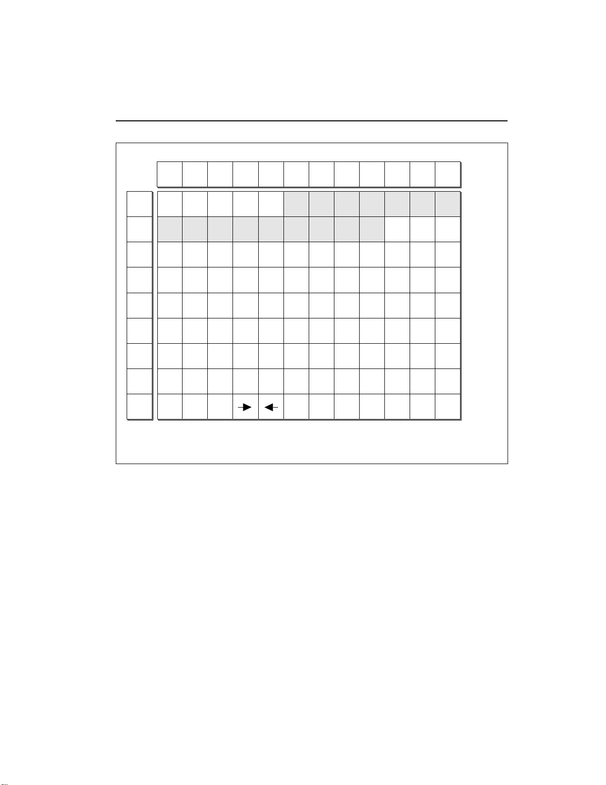
DISABLE OUTPUTS
1 5 9 13
---- ---- ---- ----
x
Page 54

3-26
Special
4. When the cursor is under the channel to be edited, press Off
to disable, or On to enable.
indicated by a small X below the channel number.
If the channel is disabled, it will be
5. Press ENTER to exit the submodule.
Module Identifier.
■
3. Recalibrate
With this function you can select minimum and maximum values for
the data slider, volume slider, left wheel, right wheel, keyboard
pressure, and foot pedal. You can also select a center value for the left
wheel. If you feel that one or more of the realtime controllers is not
operating correctly, or the EIII seems to drift in pitch, it may be time
to recalibrate. This procedure should be done periodically since the
analog componants used in the realtime controls may change over
time.
1. Activate Master module.
2. Select 8. Special, 3. Recalibrate (8/3).
3. Select the controller to be recalibrated and press ENTER.
The EIII will return to the
RECALIBRATE
3 Left Wheel
Value:
Select a Controller
4. While holding the wheel in position,vary the control to select
the minimum desired value, then press ENTER.
RECALIBRATE
3 Left Wheel
Min: 0015
Set Minimum Value
5. Vary the control to select the maximum desired value, then
press ENTER.
Page 55

RECALIBRATE
3 Left Wheel
Min: 0015 Max:6BE3
Set Maximum Value
6. If you are recalibrating the left wheel, then vary the left wheel
to select the center desired value. Press ENTER.
RECALIBRATE
3 Left Wheel
Center: 3A34
Set Center Value
7. Vary the control and check the range covered by each control,
then press ENTER.
This should be in the range of 0 to 255.
RECALIBRATE
3 Left Wheel
Value: 127
Check Value
Special
3-27
8. To save the calibration, press Yes. To cancel the recalibration,
press No.
higher-numbered controller to be recalibrated. Upon initiating this
step and after reaching the last control to be recalibrated, the EIII will
return to the Module Identifier.
■
4. Footswitch Polarity
With this function you can choose whether a footswitch’s open or
closed state will be interpreted as on by the Emulator III.
1. Activate Master module.
2. Select 8. Special, 4. Footswitch Polarity (8/4).
3. Select the desired footswitch polarity.
In either case, the display will jump ahead to the next
■
The pitch wheel and volume
slider must be “flipped” after
recalibration to assume their
correct positions.
Page 56

3-28
Special
■
You must exit the recalibration menu and hit the foot
switch twice to see the effect of
changing the footswitch polarity.
FOOTSWITCH POLARITY
Footswitch On=Closed
Select Open/Closed
4. Press ENTER to exit the submodule.
Module Identifier.
■
5. Dynamic Allocation
This function bypasses existing zone-to-output channel assignments, and makes all zones available at all channels.
1. Activate Master module.
2. Select 8. Special, 5. Dynamic Allocation (8/5).
3. Select whether dynamic allocation is on or off.
The EIII will return to the
DYNAMIC ALLOCATION
Mode: off
Select on/off
4. Press ENTER to exit the submodule.
Module Identifier.
■
6. Software Version
1. Activate Master module.
2. Select 8. Special, 6. Software Version (8/6).
The EIII will return to the
SOFTWARE VERSION
Emulator III
© 1988 E-mu Systems
Jan 18,1999 v1.2
Page 57

3. The display shows the RAM software version.
Special
3-29
4. Press ENTER to exit the submodule.
Module Identifier.
■
7. MIDI Globals
MIDI Global commands override the MIDI settings programmed for
each preset in the Preset Definition module and return us to a simpler
time when MIDI settings affected all presets. When MIDI Globals are
On, the MIDI settings for each preset are ignored (except Realtime
Controls). When MIDI Globals are turned Off, the MIDI settings for
each preset are valid. For explanations of each MIDI parameter refer
to the Preset Definition module, 6. MIDI.
1. Activate Master module.
2. Select 8. Special, 7. MIDI Globals (8/7).
3. Move the cursor to the parameter(s) to be adjusted, and select
the desired value(s) with the data slider.
The EIII will return to the
The first page shows:
MIDI GLOBALS: off
Basic Channel: 1
MIDI Mode: omni
MIDI Overflow: on
4. Select page two by pressing the right cursor button.
second page shows:
MIDI GLOBALS
Send Preset Chg: on
Recv Preset Chg: on
Send Start/Stop: on
5. Select page three by pressing the right cursor button.
third page shows:
The
The
Page 58

3-30
Special
MIDI GLOBALS
Recv Start/Stop: on
Send Clocks Only: on
Recv Clocks Only: on
6. Select page four by pressing the right cursor button.
fourth page shows:
The
MIDI GLOBALS
Local Control: on
■
8. Volume Pedal Global Override
This command overrides any footpedal assignments made in the
Realtime Control submodule and forces the footpedal to become a
volume pedal.With the pedal in the "up" position, the EIII will have
no output; With the pedal fully depressed, the level of each zone will
be equal to the VCA Level setting as specified in Analog Processing
#2. Volume Pedal Global Override can be turned "On" or "Off"
(default is Off). This setting is stored as part of the "System Software"
and will remain in its setting after the EIII is powered down and rebooted. The Volume Pedal Override allows the VCA levels of each
zone to retain their respective level differences in relationship to
each other.Volume Pedal Global works both locally and over MIDI.
To receive volume pedal data over MIDI, make sure that each preset
that is to receive pedal data is set to the same MIDI controller number
(as specified in the MIDI submodule, Preset Definition, #6).
1. Activate Master module.
2. Select 8. Special, 8. Volume Pedal (8/8)
VOLUME PEDAL
Global Override: off
Page 59

3. Select whether volume pedal global override is on or off.
3-31
4. Press ENTER to exit the submodule.
Module Identifier.
■
9. MIDI Load Bank
This feature allows a MIDI command to load banks from the hard
disk. The "Magic Preset" is a preset number which tells the EIII that
the next preset change command that it receives over MIDI is the
bank number to be loaded. Therefore, to load a hard disk bank over
MIDI, two program change commands must be sent, the "Magic
Preset" and the bank number. For example, if the "Magic Preset" is set
at "P85", and the EIII receives a preset change command of 85
followed by a preset change command of 11, the EIII will load bank
11 from the hard disk. If multiple SCSI drives are connected, the EIII
will load from the drive most recently accessed. The "Magic Preset"
is user definable and can be turned off or set to any preset number
from 0 to 99. MIDI Load Bank always works, regardless of MIDI
Global or MIDI submodule settings.
1. Activate Master module.
2. Select 8. Special, 9. MIDI Load Bank (8/9).
The EIII will return to the
MIDI LOAD BANK
Magic Preset:
Pxx Off
3. Select the Magic Preset or Off to disable MIDI Load Bank.
4. Press ENTER to exit the submodule.
Module Identifier.
The EIII will return to the
Page 60

3-32
Page 61

4-SAMPLE
1. LOAD SAMPLE 4-2
2. RENAME SAMPLE 4-4
3. ERASE SAMPLE 4-5
4. COPY SAMPLE 4-6
5. SETUP 4-7
6. PLACE SAMPLE 4-9
7. ARM SAMPLING 4-11
8. FORCE SAMPLING 4-12
9. MIDI SAMPLE DUMP 4-13
0. SELECT SAMPLE 4-15
Page 62

4-2 Load Sample
1. LOAD SAMPLE
Samples can be loaded individually from the internal hard disk, or
external storage devices.
1. Activate Sample module.
2. Select Submodule 1.
3. If you wish to select a different drive, then press the up cursor
button. If not, proceed to step five.
4. Select the drive containing the sample to be loaded, then
press ENTER.
LOAD SAMPLE from
D1 Internal HD
Select a Drive
5. Select the bank that contains the sample to be loaded, then
press ENTER.
LOAD SAMPLE from
D1 Internal HD
B00 Current Bank
Select a Bank
6. Select the sample to be loaded, then press ENTER.
scroll through the samples, the display shows the names of the
existing samples, whether stereo or mono, sampling rate, and
sample length.
As you
Page 63

LOAD SAMPLE from
S00 Current Sample
Stereo 44100Hz
3.0secs
7. Select the destination sample number into which the source
sample will be loaded, then press ENTER.
an existing sample, you will be asked if you do want to overwrite.
Enter Yes to replace the existing sample, No to cancel the operation.
If you try to overwrite
LOAD SAMPLE into
S00 Selected Sample
S00 Empty Sample
Select Dest Sample
4-3Load Sample
8. If desired, rename the sample.
changed with the left and right cursor buttons. Select the desired
characters by using the ten key pad, data slider and keyboard. You
can also use the up cursor to insert spaces and the down cursor to
delete spaces. (See Sample, 2. Rename Sample.)
9. Press ENTER to exit the submodule.
Module Identifier.
Choose the characters to be
The EIII will return to the
Page 64

4-4
Rename Sample
2. RENAME SAMPLE
This submodule allows you to rename any sample.
1. Activate Sample module.
2. Select Submodule 2.
3. Scroll through the samples available for renaming, then press
ENTER.
S00 Current Sample
RENAME SAMPLE
Select a Sample
■
Use the data slider or Increment/Decrement buttons to
access the full character set.
The keyboard does not have
enough keys to access all
available characters.
4. Rename the sample.
the right and left cursor buttons. Select the desired characters by
using the ten key pad, data slider and keyboard. You can also use the
up cursor to insert spaces and the down cursor to delete spaces.
Choose the characters to be changed with
RENAME SAMPLE
S00 Untitled Sample
[0-9]/Slider/Kybd
5. Press ENTER to exit the submodule.
Module Identifier.
The EIII will return to the
Page 65

3. ERASE SAMPLE
Individual samples can be erased from the bank loaded into the
Emulator III, and newly created locked samples currently in memory can be erased using this function.
1. Activate Sample module.
2. Select Submodule 3.
3. Select the sample to be erased, then press ENTER.
ERASE SAMPLE
S00 Current Sample
Select a Sample
4. If the sample is stereo, select whether you want to erase the
left side, right side, or the entire stereo sample.
4-5Erase Sample
ERASE SAMPLE
S00 Selected Sample
Side: Stereo
Select L/R/Stereo
5. Decide if you really want to erase the sample.
inquire if you are sure.
6. Press Yes to erase the sample, or No to cancel the operation.
In either case the EIII will return to the Module Identifier.
The EIII will
Page 66

4-6 Copy Sample
4. COPY SAMPLE
Samples can be copied to other sample numbers within the same
bank.
1. Activate Sample module.
2. Select Submodule 4.
3. Select the sample to be copied, then press ENTER.
4. Select the destination sample number into which the source
sample will be copied, then press ENTER.
an existing sample, you will be asked if you do want to overwrite.
Enter Yes to replace the existing sample, or No to cancel the
operation.
COPY SAMPLE from
S00 Current Sample
Select Source Sample
If you try to overwrite
COPY SAMPLE to
S00 Selected Sample
S00 Empty Sample
Select Dest Sample
5. Rename the sample.
the right and left cursor buttons. Select the desired characters by
using the ten key pad, data slider and keyboard. You can also use the
up cursor to insert spaces and the down cursor to delete spaces.
6. Press ENTER to exit the submodule.
Module Identifier.
Choose the characters to be changed with
The EIII will return to the
Page 67

In this submodule, you will prepare the Emulator III for sampling.
When sampling, make sure all proper connections have been made.
If you are sampling in stereo, plug into the left and right sample
input jacks. If you are sampling in mono, plug into either the left or
right sample input jack.
Setup
5. SETUP
4-7
1. Activate Sample module.
number shown on the display, you need do nothing except proceed
to the next step. To sample into a different sample number, refer to
0. Select Sample.
2. Select Submodule 5.
3. Use the cursor buttons to select one of the following parameters to edit.
Page one displays:
If you want to sample into the sample
SAMPLE SETUP
Thresh: |
L : O n ||||||| |
R: Off |
■ VU Meters: Set the sample level with the sample input slider so
that the left and right side meters indicate optimum sampling level.
This is defined as the maximum level short of reaching the extreme
right side of the display.
■ Thresh: (Threshold) Set the sampling threshold with the data
slider. If you arm sampling (7. Arm Sampling) and the signal to be
sampled exceeds the threshold, sampling will begin.
■ L: (Left Channel) Line three shows the left input level, record
status, and whether on or off. Press On or Off to enable or disable
recording into the left channel. When sampling into one channel
only, turn off the other channel to conserve memory.
■ R: (Right Channel) Line four shows the right input level, record
status, and whether on or off. Press On or Off to enable or disable
recording into the left channel. When sampling into one channel
only, turn off the other channel to conserve memory.
4. Select page two by pressing the right cursor button.
shows:
Page two
Page 68

4-8
Setup
■
Line four displays how much
sampling time is left in memory. The sample length set on
line three cannot exceed this.
SAMPLE SETUP
Rate: 44053Hz
Length: 100.3secs
120.4secs Available
■ Rate: Choose between 44053 Hz (20 kHz bandwidth, maximum
fidelity) or 33333 Hz (15 kHz bandwidth, uses less memory) sample
rate.
■ Length: This allows you to select the amount of sampling (recording) time. The maximum available length depends on the amount of
memory available and the sampling rate.
5. Select page three by pressing the right cursor.
shows the following parameters:
Page three
SAMPLE SETUP(Auto)
Truncate: off
Normalize: absolute
Placement: 24 Keys
■ Truncate: automatically truncates the start, end, or both start and
end as soon as the sample is taken. Selecting Off disables autotuncation.
■ Normalize: increases the amplitude of a sound until the peak
amplitude of the loudest sample reaches 100% of full scale. If either
Absolute or Relative is selected this is done automatically after the
sample is taken. Selecting Off disables auto-normalization. Relative
increases the amplitude of stereo samples until the peak sample of
either the left or right sample reaches 100% of full level. The relative
amplitudes of the left or right samples remain intact. Selecting
absolute will increase the amplitude of both the left and right
samples to full level. When sampling in mono, selecting absolute or
relative makes no difference.
■ Placement: selects the transposition range in which new samples
will be placed. For example, selecting a range of 24 keys places the
next sample over a 24 key range with the original pitch in the center
of that range. Selecting white keys places each new sample on the
next white key, which is useful for sound effects.
6. Press ENTER to exit the submodule.
Module Identifier.
The EIII will return to the
Page 69

6. PLACE SAMPLE
Samples in the bank can be placed to cover a particular range of the
keyboard. The exact pitch shifting range depends on the sample rate.
Place Sample
4-9
1. Activate Sample module.
sample number and name. If this is not the sample you want to place,
refer to Sample, 0. Select Sample.
2. Select Submodule 6.
3. Select whether you want to place the sample to a primary or
secondary zone, then press ENTER.
The display will show the current
PLACE SAMPLE
pri
Select pri/sec
4. Select the original pitch of the sample, then press ENTER.
you select notes, the display will show the samples mapped into the
preset.
As
PLACE SAMPLE
pri G1
Select Original Key
5. Select the lowest key of the sample range, then press ENTER.
The display will indicate the preset status (described in step four).
PLACE SAMPLE
pri G1 C1
Select Low Key
Page 70

4-10
■
Preset templates may be
created by assigning empty
samples and analog parameters to keyboard locations and
then saving the bank.
Place Sample
6. Select the highest key of the sample range, then press ENTER.
The display will indicate the preset status (as described in step four).
PLACE SAMPLE
pri G1 C1 to B1
Select High Key
7. If the display asks
overwrite, or N o to return to the Module Identifier.
Yes to overwrite, any previously assigned samples that fall within
the just-specified keyboard zone will be de-assigned from that zone.
Overwrite Zone? Overwrite Zone?
Overwrite Zone?
Overwrite Zone? Overwrite Zone?
press Yes to
If you press
Page 71

7. ARM SAMPLING
Upon initiating this submodule, the Emulator III will begin sampling as soon as the sound to be sampled exceeds the threshold set
in Sample, 5. Setup. The EIII will actually capture samples just before
the threshold is exceded to preserve the attack portion of the sound
(12mS at 44100Hz, 17mS at 31000Hz).
1. Activate Sample module.
Arm Sampling
4-11
2. Select Submodule 7.
sample prior to arming, the first empty sample will be automatically
selected. To overwrite an existing sample, erase it first.
3. Play the sound to be sampled.
the threshold set in 5. Setup, the display will indicate that sampling
has begun.
4. Terminate sampling.
the end of the sample length set in 5. Setup, or if the EIII runs out of
memory. To stop sampling manually, press ENTER. In any case, the
display will return to the Module Identifier.
5. Decide if you like the sample.
the sample, re-arm sampling or force sampling and re-sample before
de-activating the module. Once you de-activate the module, the
sample will be locked against re-sampling. To erase a locked sample,
use 3. Erase Sample.
If you did not select a specific empty
When the sound level exceeds
This will occur automatically after reaching
Play the keyboard. If you don't like
■
If the input was clipped during sampling the display will
say
Overload
.
Page 72

4-12
Force Sampling
8. FORCE SAMPLING
Force Sampling lets you initiate sampling manually as an alternative
to threshold-sensitive sampling. This is useful for situations where
the signal to be sampled is more or less continuous. Continuous
signals greatly complicate the threshold-setting process described in
Sample, 5. Setup. Upon initiating this submodule, the Emulator III
will begin sampling immediately.
1. Activate Sample module.
■
If the input was clipped during sampling the display will
say
Overload
.
2. Select Submodule 8 when you are ready to begin sampling.
you did not select a specific empty sample prior to force sampling,
the first empty sample will be automatically selected. To overwrite
an existing sample, erase it first.
If
3. Wait as the signal is sampled.
4. Terminate sampling.
the end of the sample length (if set in 5. Setup), or if the EIII runs out
of memory. To stop sampling manually, press ENTER. In any case,
the display will return to the Module Identifier.
5. Decide if you like the sample.
the sample, re-arm sampling or force sampling again and re-sample
BEFORE de-activating the module. Once you de-activate the module, the sample will be locked against re-sampling.
This will occur automatically after reaching
Play the keyboard. If you don't like
Page 73

9. SAMPLE DUMP
Sample Dump allows sample data to be transferred to and from the
Emulator Three using the MIDI Sample Dump Standard. The EIII
can transmit sample data with a word size of either 14 or 16 bits
(Certain instruments such as the SP-1200 require the use of the 14 bit
word size). In addition, for instruments that use 14 bits or less, 14 bit
mode transmits data 30% faster.
4-13
Before initiating MIDI Sample Dump, make sure that the MIDI
cables are properly connected. A single MIDI cable (open-loop) is
sufficient but the data transfer will be much faster if two MIDI cables
are used (closed-loop). The closed-loop allows the two units to
handshake and prevents idle time between each data packet. The
cables should be connected between the MIDI In and MIDI Out of
both units.
In the Sample Dump Standard and in the EIII, samples are assigned
numbers. The EIII sample number and the MIDI sample number
remain the same. For example, sample #36 transferred from another
device to the EIII will be placed in sample location 36.
When transferring samples to the Emax, the sample location numbers correspond to sample dump MIDI key numbers. For example,
a sample placed in location #60 in the EIII, once transmitted, will be
placed on MIDI key #60 (middle C) of the Emax. If sample location
#36 is chosen as a reception location on the EIII, the EIII will request
that the sample placed on MIDI key # 36 (C1) of the Emax be sent.
1. Activate Sample module.
2. Select Submodule 9.
3. Select whether you want to transmit or receive a sample and
press ENTER.
EIII
MIDI
In
MIDI
Out
Computer
or Sampler
■
A "closed-loop" connection
greatly accelerates MIDI data
transfer.
MIDI
Out
MIDI
In
SAMPLE DUMP
Direction: Transmit
Select Direction
Page 74

4-14
■
Sampling with the EIII and
transmitting the data to other
samplers can dramatically
improve the quality of the
other sampler's sounds.
4. Select the word size and press ENTER.
SAMPLE DUMP
Direction: Transmit
Word Size: 16 Bits
Select 14/16 Bits
5. Select a sample to be transmitted and press ENTER.
selected sample is stereo, the EIII will ask you to select which side is
to be transmitted.
If the
SAMPLE DUMP
Direction: Transmit
S01 Selected Sample
Select a Sample
6. Press ENTER to begin the Sample Dump.
Page 75

0. SELECT SAMPLE
This submodule selects a sample for placing on the keyboard, or the
sample into which a sound will be recorded.
1. Activate Sample module.
2. Select Submodule 0.
Select Sample
4-15
3. Select the desired sample and press ENTER.
through non-empty samples, the display will show the sample
number, name, sampling rate, sampling length, how many presets
use the sample, and whether the sample is stereo, left, or right. And,
as you scroll through the samples, they will be playable on the
keyboard. Is that considerate, or what?
As you scroll
SELECT SAMPLE
S00 Selected Sample
Stereo 44100Hz
10 Presets 120.3secs
Page 76

4-16
Page 77

5-PRESET MANAGEMENT
1. LOAD PRESET 5-2
2. RENAME PRESET 5-4
3. ERASE PRESET 5-5
4. COPY PRESET 5-6
5. CREATE PRESET 5-7
6. PRESET SIZE 5-8
7. STACK MODE 5-9
8. VELOCITY SWITCH 5-10
LEVEL
Page 78

5-2
Load Preset
1. LOAD PRESET
A preset, with its samples, can be loaded from the internal hard disk
or external storage devices.
1. Activate Preset Management module.
2. Select Submodule 1.
3. If you wish to select a different drive, move the cursor to the
drive number. If not, go to step 5.
4. Select the drive containing the preset to be loaded, then press
ENTER.
LOAD PRESET from
D1 Internal HD
Select a Drive
5. Select the bank number that contains the preset to be loaded,
then press ENTER.
LOAD PRESET from
D1 Internal HD
B00 Current Bank
Select a Bank
6. Select the preset to be loaded, then press ENTER.
LOAD PRESET from
P00 Current Preset
Select Source Preset
Page 79

7. Select the destination preset number into which the source
preset will be loaded, then press ENTER.
an existing preset, you will be asked if you are sure. Enter Yes to
replace the existing sample, or No to cancel the operation.
If you try to overwrite
LOAD PRESET into
P00 Selected Preset
P00 Empty Preset
Select Dest Preset
8. If desired, rename the preset.
changed with the left and right cursor buttons. Select the desired
characters by using the ten key pad, data slider and keyboard. You
can also use the up cursor to insert spaces and the down cursor to
delete spaces. (See 2. Rename Preset.)
Choose the characters to be
5-3Load Preset
■
If you load a preset that uses
samples already present in
the bank, new copies of the
samples will not be loaded.
This technique saves a great
deal of memory space. However the samples must be
identical, even to the name,
otherwise new samples will be
loaded.
9. Press ENTER to exit the submodule.
Module Identifier.
The EIII will return to the
Page 80

5-4
Rename Preset
2. RENAME PRESET
This submodule allows you to rename any preset in the Emulator
III's current bank.
■
Use the Data Slider or Increment/Decrement buttons to
access the full character set;
the keyboard does not have
enough keys to access all
available characters.
1. Activate Preset Management module.
2. Select Submodule 2.
3. Scroll through the presets available for renaming. When the
display shows the desired preset, press ENTER.
RENAME PRESET
P00 Current Preset
Select a Preset
4. Rename the preset.
left and right cursor buttons. Select the desired characters by using
the ten key pad, data slider, and keyboard. You can also use the up
cursor to insert spaces and the down cursor to delete spaces.
Choose the characters to be changed with the
RENAME PRESET
P00 Untitled Preset
[0-9]/Slider/Kybd
5. Press ENTER to exit the submodule.
Module Identifier.
The EIII will return to the
Page 81

3. ERASE PRESET
Individual presets, with or without their samples, can be erased from
the bank loaded into the Emulator III to free up memory space.
1. Activate Preset Management module.
2. Select Submodule 3.
3. Select the preset to be erased, then press ENTER.
Erase Preset
5-5
ERASE PRESET
P00 Current Preset
Select a Preset
4. Press Yes to erase the preset, or No to cancel the operation.
If the preset you are erasing contains samples unique to this preset,
you will be asked if you want to Erase Samples Also? Enter Yes
to erase the unique samples, or No to erase the preset. In either case
the EIII will return to the Module Identifier.
■
Erasing a preset won’t necessarily free up sample memory if the same samples are
used in other presets that are
not erased.
Page 82

5-6
Copy Preset
4. COPY PRESET
Presets can be copied to other preset numbers within the same bank.
This is useful if you want to create variations on a particular preset.
■
Copying a preset will not
make copies of the samples
used in the preset.
For example, you may want to alter the MIDI, velocity, or arpeggiator setups, or Analog Processing parameters.
1. Activate Preset Management module.
2. Select Submodule 4.
3. Select the preset to be copied, then press ENTER.
4. Select the destination preset number into which the source
preset will be copied, then press ENTER.
an existing preset, you will be asked if you want to overwrite. Press
Yes to replace the existing sample, or No to cancel the operation.
COPY PRESET from
P00 Current Preset
Select Source Preset
If you try to overwrite
COPY PRESET into
P00 Selected Preset
P00 Empty Preset
Select Dest Preset
5. If desired, rename the preset.
changed with the left and right cursor buttons. Select the desired
characters by using the ten key pad, data slider and keyboard. You
can also use the up cursor to insert spaces and the down cursor to
delete spaces.
6. Press ENTER to exit the submodule.
Module Identifier.
Choose the characters to be
The EIII will return to the
Page 83

5. CREATE PRESET
An empty preset must be initialized by the Emulator III before it can
hold samples. This initialization process is called creating a preset.
1. Activate Preset Management module.
2. Select Submodule 5.
Create Preset
5-7
3. Select the preset to be created, then press ENTER.
to overwrite an existing preset, you will be asked if you want to
overwrite. Enter Yes to replace the existing preset, or No to cancel the
operation.
If you try
CREATE PRESET
P00 Empty Preset
Select a Preset
5. If desired, rename the preset.
changed with the left and right cursor buttons. Select the desired
characters by using the ten key pad, data slider and keyboard. You
can also use the up cursor to insert spaces and the down cursor to
delete spaces.
6. Press ENTER to exit the submodule.
Module Identifier.
Choose the characters to be
The EIII will return to the
Page 84

5-8
Preset Size
6. PRESET SIZE
■
The percentages of sample
memory used may add up to
considerably more than 100%
if the same samples are used
in several presets.
How much bank memory does a preset require? Use this function to
find out.
1. Activate Preset Management module.
2. Select Submodule 6.
3. Scroll through the preset numbers and select the Preset
whose size you want to check.
preset, the third line the amount of preset memory used (both as a
percentage of the total bank memory and as an absolute number of
bytes), and the fourth line the amount of sample memory used (both
as a percentage of the total bank memory and as an absolute number
of bytes).
The second line shows the selected
PRESET SIZE
P00 Current Preset
Preset:3.5% 1962
Sample:27.9% 877020
4. Press ENTER to exit the submodule.
Module Identifier.
The EIII will return to the
Page 85

7. STACK MODE
Stack Mode allows you to place multiple presets on each key of the
keyboard. In stack mode, the current preset can be linked with
another preset. The linked preset can in turn, be linked with another
preset and so on until all of the available channels are used up. As an
example, suppose you link preset 01 to preset 02 and that preset 02
has previously been linked to preset 08. When preset 01 is played,
presets 02 and 08 will play as well. When preset 02 is played, preset
08 will also play. The polyphony of the Emulator III will vary
according to the voice architecture of each preset in the stack. If two
presets are linked to themselves, forming a loop, those two presets
will play in unison up to the 16 channel limit of the EIII.
Stack Mode
5-9
Link to:
P02
Preset 01 Preset 02 Preset 08
1. Select the current preset.
2. Activate Preset Management module.
3. Select submodule 7.
4. Use the data slider to choose the preset (or none) that will be
linked to the current preset.
Link to:
P08
STACK MODE
Link to:
Pxx No Link
5. Press ENTER to exit the submodule.
Module Identifier.
The EIII will return to the
Page 86

5-10
Velocity Switch
8. VELOCITY SWITCH LEVEL
The velocity cross-switch function in the Preset Definition module,
(5. Crossfade/Switch) allows overlapping samples to be switched
according to key velocity. This function sets the velocity at which
samples are cross-switched.
1. Activate Preset Management module.
2. Select submodule 8.
3. Use the data slider to select the velocity at which samples will
be cross-switched.
Level:64
Velocity values range from one to 127.
VEL SWITCH LEVEL
4. Press ENTER to exit the submodule.
Module Identifier.
The EIII will return to the
Page 87

6-DIGITAL PROCESSING
BACKGROUND 6-2
1. SETUP 6-10
2. LOOP 6-13
3. TRUNCATION 6-16
4. COPY SECTION 6-17
5. CUT SECTION 6-19
6. PASTE SECTION 6-21
7. SAMPLE RATE 6-25
CONVERSION
8. DIGITAL EFFECTS 6-26
1. Digital Tuning 6-26
2. Taper 6-27
3. Gain Change 6-29
4. Reverse Section 6-31
5. Stereo<->Mono 6-32
6. Sample Calculator 6-33
7. Left<->Right 6-33
8. Ping Pong 6-33
9. Digital Delay 6-36
0. Digital Effects 2 6-38
9. UNDO 6-46
0.SELECT SAMPLE 6-48
Page 88

6-2
Digital Processing
BACKGROUND: ABOUT LOOPING
Sampling is the process of storing sounds in digital memory. Since
each individual sample (not the complete sample, but each element
of the sample) requires one memory slot, memory requirements
increase if you sample long sounds or use high sampling rates.
The Emulator III does not scrimp on memory. It has more than a
stock Mac Plus or SE, Amiga, and Atari ST computer put together.
But memory capacity is finite. Cost considerations dictate how much
memory can be included...which brings us to looping.
■ How Looping Works: Looping is a technique that can extend a
sound’s length without using lots of memory. It is based on the fact
that many sounds start off with a complex attack transient, then
settle down to a comparatively steady sound. Listen carefully to a
Loop
Page 89

plucked guitar string. The first part of the sound consists of a
generally complex mixture of pick noise and several harmonics;
after a while, the string decays down to a pretty steady repetitive
waveform.
Since the latter part of the waveform is repetitive, there is no need to
waste memory sampling several seconds of it. Instead, you can mark
off a loop of the repetitive section, and instruct the EIII to play that
looped section for as long as the key is held down. After playing to
the end of the loop, the EIII will jump back to the beginning of the
loop and play through the loop again. This process repeats until you
release the key playing back the sample.
■ Looping Saves Memory: Since the loop can repeat indefinitely,
any samples that occur past the loop end are unneeded. Therefore,
you can truncate those samples, and free up the memory they used.
■ Creating Attack and Decay Characteristics for the Looped Portion: One potential problem is that the loop repeats at the same level.
This is usually acceptable for sustaining instruments (flute, organ,
brass, etc.), but is unacceptable for plucked or struck sounds, which
decay over time. Fortunately, the Analog Processing module provides a means to shape the attack, sustain, and decay characteristics
of a sample. You can create a decay during the looped portion, and
simulate pluck or struck sounds.
Digital Processing
6-3
Artificial Decay can be applied to a looped sound.
■ Different Ways of Looping: Another potential problem is that loop
beginning and end points must be very carefully chosen for the best
sounding loop. If there is a level shift between the beginning and end
of the loop, a pop or tick will sound every time the loop jumps from
the end of the loop back to the beginning. The Emulator III offers four
different ways to overcome this notorious problem:
■ Auto Correlation: The EIII’s computer examines the loop
points, and shifts your estimated loop start and end points
to provide the best possible loop within the vicinity of the
estimated loop points you set.
Page 90

6-4
Digital Processing
■ Forward/Backward Looping: With this type of loop, the EIII plays
to the end of the loop, then reverses direction and plays backward to
the beginning of the loop. It then reverses itself and plays forward to
the loop end, repeating this process for as long as the key is held
down. Forward/backward looping is usually most effective with
fairly long loops.
...then replays the marked loop for
as long as the key is held down.
First the note
plays to the end
of the loop...
- Size -
Start-
- End
■ Loop Compression: The looped section of the sample can be
compressed, which "evens out" any changes in amplitude. Changes
in amplitude can cause "breathing" effects, thumping or clicks.
■ Crossfade Looping: The Emulator III fades between the beginning
and end of the loop so that as the end fades out, the beginning fades
in. This virtually eliminates the clicks and pops that can occur with
other types of looping.
Source Data is faded in and out with this data
Loop Start Loop End
CROSSFADE LOOPING. Crossfade Looping takes sound data from around
the loop start point and fades it into the sound data around the loop end point
so that the data at those loop points is identical.
Page 91

Digital Processing
6-5
BACKGROUND: CUT, COPY, PASTE, & UNDO
Imagine a printout of a sample. Now imagine that you have a pair
of scissors capable of cutting a piece out of that sample (or a copy of
that piece if you don’t want to affect the original), as well as a
clipboard to neatly hold the cut or copied piece. Now imagine that
you can either perfectly insert the clipboard contents at any given
point in any sample, or mix the clipboard contents in with any
sample, starting at any designated point. The Emulator III can do all
this, and all electronically. The EIII also provides Auto Correlation
and optional Crossfade functions that result in seamless transitions
between the cut, copied, and pasted parts.
■
The clipboard contents are
designated as Sample 00.
Sample 00
CLIPBOARD DATA. The clipboard will retain data until replaced by other data to be copied, cut, or backed up. This
occurs with several EIII operations where you want to be able to undo an action that doesn’t work out as anticipated.
Since clipboard data stays intact when you call up another sample, data can be cut or copied from one sample and
pasted to another.
■ Undo and Redo: During several Emulator III digital processing operations such as cut, paste, and
Page 92

6-6
Digital Processing
sample rate conversion, the EIII will automatically back up the
sample being processed and store this backup on the system drive.
If you do not like the results of the processing, you can call up the
Undo function, and restore the original sample from the system
drive. (Ah, if only life itself was so simple.) Best of all, the processed
sample will now move onto the system drive. Thus, if you decide you
liked the processed version better after all, you can actually undo the
undo. (Redo.)
■ Insufficient System Drive Memory: The display will inform you if
there is not enough memory to back up a sample onto the system
drive. You then have two choices: either free up some additional
memory by erasing banks on the system drive, or call up the Undo
function (Digital Processing, 9. Undo) and disable the backup process. Of course, if backup is disabled, you will not be able to undo an
operation.
■ Typical Applications: Typical cut/copy/paste applications
would be to splice the beginning of one sample to the end of
another,or to mix two samples together to conserve memory. (Do
this by copying an entire sample, then pasting it at the beginning of
the second sample using the mix option.) You can splice an attack
transient on to a synthesizer waveform loop to produce realistic
sounds that take up virtually no memory, or take out a pop or click
in a sample. Another possibility is for flanging and chorusing. Paste
(mix) a sample to itself, offset from the beginning by a few hundred
samples or so, to thicken up the sound.
We suggest you practice cut, copy, and paste techniques on a spoken
phrase. Samples of political speeches can be particularly amusing
when subjected to cut and paste operations.
This submodule lets you select the type of loop, the playback mode,
Page 93

BACKGROUND: THE SCRUB WHEEL
The Scrub Wheel is an Emulator III function that allows you to use
the pitch wheel in many Digital Processing functions to quickly
move through a sound, similar in concept to rocking the reels of a
reel-to-reel tape recorder. The scrub wheel makes it easy to locate a
particular section of a sound because you are able to hear the sound
as you move through it.
To use the scrub wheel, move the pitch wheel of the EIII or your MIDI
keyboard while in a Digital Processing function such as Truncation
or Looping. If the pitch wheel is moved slightly forward, the sound
will play slowly through its length. If the wheel is pushed forward
all the way, the sound will play through faster. If the wheel is moved
backwards (towards you) the sound will play backwards through
the sound. The scrub wheel operates like the accelerator on your car:
the harder you press it, the faster it goes. The scrub wheel can be
calibrated to your own preference in Digital Processing, 1. Setup. If
the scrub wheel does not seem to work properly, the left wheel may
need recalibration. (Refer to the Recalibration function, located in
the Master module, 8. Special, 3. Recalibrate.)
Digital Processing
6-7
FAST
FORWARD
SLOW
STOP
SLOW
REVERSE
FAST
EMULATOR THREE SCRUB WHEEL. Move the wheel slightly to advance
slowly through the sound. Move the wheel more to advance quickly through
the sound.
Page 94

6-8
Digital Processing
BACKGROUND: AUTO CORRELATION AND
ZERO CROSSING
Auto Correlation
First of all, just what does auto correlation mean? Auto correlation
simply means automatic correlation or comparison. The computer
analyzes the signal around the loop points you have specified and
then moves the end point of the loop until it finds a section of the
wave that closely matches the section around the start point. Auto
correlation may be used again and again with the computer moving
the analysis window slightly each time to try to zero in on the
optimum loop.
Zero Crossing
The term zero crossing refers to the point at which the positive slope
of a waveform passes through zero. In many digital processing
applications, such as splicing and looping, it is useful to locate zero
crossings in order to make glitch-free joins and loops. On some
signals, however, a simple zero crossing may not be effective because the signal contains excessive noise or low-level, high-frequency harmonics. In these cases, every few samples may cross
through zero. By setting a zero crossing threshold, we can ignore
low-level zero crossings and wait for the signal to reach a certain
level before choosing the next zero-crossing. Zero crossing threshold
sets a level that a signal must exceed before the next zero crossing
with a positive slope is selected. The selected zero crossing threshold
is used in the Auto-Truncate function (Sample, 5. Setup) or whenever you manually select a zero crossing using the cursor keys.
The diagrams on the following page illustrate zero crossing in action.
The small x marks the initial position. To move forward through the
sound to the next zero crossing, press the right cursor button, as
shown in the upper diagram. The EIII will find the first zero crossing
on the positive slope after the signal has crossed the designated
threshold.
To move backward through the sound to the next zero crossing, as
shown in the lower diagram, press the left cursor button. The EIII
will find the first zero crossing on the positive slope after the signal
has crossed the designated threshold.
Page 95

Ignored
Zero X Threshold
(Set at -30 dB)
Selected
Slope of
wave
Slope of
wave
Digital Processing
6-9
Ignored
Selected
ZERO CROSSING POINTS. To move forward through the sound to the next zero crossing, press the right cursor.
To move backward through the sound to the next zero crossing, press the left cursor. The Emulator III will find the
first zero crossing on the positive slope after the signal has crossed the designated threshold.
Page 96

6-10
1. SETUP
Setup
and set various parameters concerning other Digital Processing
functions. For more information, see Background: About Looping ,The
Scrub Wheel, and Zero Crossing at the beginning of this section.
1. Activate Digital Processing module.
2. Select Submodule 1.
3. Select the loop type on line two.
SETUP
Loop Type: forward
Loop in Release: on
Reverse Playback:off
Your choices are:
Start-
■ Off: The loop is disabled and the sample plays as recorded.
■ Forward: The sample plays normally
Loop
- Size -
- End
until it reaches the end of the loop. It then
jumps back to the start point and replays
through the loop. Upon reaching the loop
end, it again re-plays the loop. This looping
process continues for as long as the key is
pressed.
■ Fwd/Bkwd: (Forward/Backward)The
sample plays normally until it reaches the
end of the loop. It then plays backward
until it reaches the start point, then reverses
direction and replays through the loop
until it reaches the loop end. At that point,
playback reverses direction again. This forward/backward looping action continues
for as long as the key is pressed.
Page 97

6-11Setup
4. Select whether Loop in Release on line three is on or off.
are your choices:
■ Off: Lifting your finger off a key initiates the release phase of the
VCA envelope. If Loop in Release is off, the loop will not continue
during the release phase. The portion of the sample after the loop will
be played during release. The signal may cut off abruptly after you
remove your fingers from the keys if the sample has been truncated
after the loop.
■ On: With Loop in Release on, the loop will keep playing—even
after you lift your finger off the key—for the duration of the VCA
release.
5. Select whether Reverse Playback on line four is on or off.
Here are your choices:
■ Off: The sample plays back as recorded.
■ On: The sample is played back in the reverse order in which it was
recorded. For example, a percussive sound, when played backwards, will have an attack time instead of a decay time.
Here
■
If a sample ends in a loop,
playing it backwards will repeat the loop. The sample will
not play back prior to the loop
start.
6. Select page two by pressing the right cursor.
SETUP
Scrub Slow: - 0 semi
Scrub Fast: + 0 semi
Beep Type: orig key
Scrub Slow sets the speed at which the sample will play when the
wheel is moved slightly. Scrub Fast sets the speed at which the
sample will play when the wheel is moved full forward or backward.
If the Scrub Slow setting is set at -12 semitones and the wheel moved
slightly forward, the sound would play as if you had hit a key one
octave down from the original pitch or at half its original speed. The
Page 98

6-12
Setup
Scrub Slow and Fast settings allow you to adjust the scrub wheel to
your personal preference.
If Beep Type is enabled, you will get an audible indication when the
digital processing is done. The second page allows you to select the
beep type on line four. Your choices are:
■ Off: no beep
■ Original Key: will play the calculated sound in the original key.
■ Metronome: will buzz the metronome.
7. Select page three by pressing the right cursor.
SETUP
Audition Sample: on
Zero X Thresh: -54dB
■
If Audition Key is "Off",
pressing a key once selects
the primary sample and pressing it again selects the secondary sample.
8. Select whether Audition Sample is on or off.
Sample "Off" allows you to listen to the current preset while working
in the Digital Processing module (default is "On"). When Audition
Sample is turned "Off", all parameters assigned to the current preset
(VCA, VCF, Realtime Controls, etc.), will remain in effect while
working in the Digital Processing module. In addition, while in the
Select Sample, Cut, Copy,or Paste functions, samples can be selected
simply by playing the keyboard.
Caution:
not be able to hear your changes until the proper preset is selected.
9. Use the data slider to select the desired zero crossing
threshold.
-30dB will be least sensitive. The selected Zero Crossing Threshold
is used in the Auto-Truncate function (Sample, 5. Setup) or whenever you manually select a zero crossing using the cursor keys. If the
Auto-Truncate function does not seem to be working well, try
adjusting the zero crossing threshold.
10. Press ENTER to exit the submodule.
Module Identifier.
This submodule allows you to specify loop start and length points.
If the current sample is not in the current preset, you will
A setting of -96dB will be most sensitive, and a setting of
Turning Audition
The EIII will return to the
Page 99

If you have a difficult time finding good loop points, the Emulator III
can assist you with the Auto Correlation function. If Auto Correlation doesn’t produce acceptable results , the beginning and end of a
loop can be Crossfaded to help mask loop discontinuities. For more
information, see Background: About Looping at the beginning of this
section.
1. Activate Digital Processing module.
2. Select Submodule 2.
Loop
6-13
2. LOOP
LOOP secs samples
Start: 1.59 35016
End: 2.43 53599
Size: 0.84 18584
3. Select the values for the start point on line two and the loop
size on line four that give the best looping effect, then press
ENTER.
size so that the loop automatically falls on positive zero crossing
points in the waveform.
The sample size equals the difference in samples between the start
and end points. These settings interact in the following ways:
4. The display will inquire if you want to Auto Correlate. Press
YES to Auto Correlate, or NO to proceed directly to step six,
Compress Loop.
niques to choose optimum loop points. Without Auto Correlation,
unless you are proficient with sampling techniques, loops will
usually have discontinuities between the splice points that can
produce annoying ticks, pops, or other glitches.
With Auto Correlation, the Emulator III looks for loop points near
The left and right cursor will change the start point and/or
■ Changing the size will automatically change the end
point, so that the difference in samples between the start
and end points remains equal to the size.
■ Changing the start point will change the end point to
maintain a constant size.
■ Changing the end point changes the size, and the start
point remains constant.
Auto Correlation uses artificial intelligence tech-
■
The loop points can be continually adjusted using the
scrub wheel or data slider
while the sound is playing.
Page 100

6-14
■
If a sample's loop disappears as soon as you have left
the Digital Processing module, check to see if the loop
function has been disabled in
Analog Procesing, 1. Setup.
Loop
LOOP secs samples
Start: 1.59 35016
End: 2.43 53599
Auto Correlate? Y/N
the ones you chose that can be spliced together with minimum
discontinuity. Occasionally it will be impossible for either you or the
EIII to locate a perfect splice point, but in most cases you’ll find that
Auto Correlation, combined with practice and experimentation, can
produce very smooth loops.
5. If desired, repeat steps three and four, until the best possible
loop results.
and carry on.
6. The display will inquire if you want to Compress the Loop.
When you’re finished looping, press NO in step four
LOOP secs samples
Start: 1.59 35016
End: 2.43 53599
Compress Loop? Y/N
Press Yes to Compress, or No to proceed directly to step seven,
Crossfade Loop.
yet another way to achieve a smooth sounding loop. Compression
"evens out" the changes in level during the loop which are perceived
by the listener as amplitude modulation.
7. Select the Crossfade Loop size and type, then press ENTER.
Crossfading means that as one part of the loop fades out, the other
fades in. Instead of butt-splicing the end of the loop back to the
beginning when forward looping, (or butt-splicing the loop end and
start points with forward/backward looping), Crossfade looping
smoothly crossfades between the two sounds on either side of the
splice. Crossfading virtually eliminates any loop glitches, although
there may be level variations instead. These variations are not as
noticeable as loop glitches. For more information, see Background:
About Looping at the beginning of this section.
Your Crossfade looping type choices are:
Compressing just the loop portion of the sound is
 Loading...