

Page 1
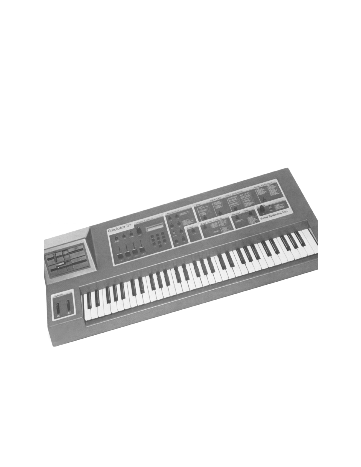
EMULATOR II+
OWNERS
MANUAL
By Craig Anderton
OS Version 3.1 and 3.1 HD
© 1985,1986,1987 E-mu Systems, Inc., Scotts Valley, CA ▪ All Rights Reserved
Restored by the Emulator Archive ▪ www.emulatorarchive.com
Page 2

CONTENTS
CONTENTS
INTRODUCTION ......................................................................................11
WHAT’S AN EMULATOR II?............................................................................................. 12
WELCOME TO THE EII+ and EII+HD ...........................................................................................13
MANUAL RESTORATION NOTES................................................................................................13
SEND IN YOUR WARRANTY CARD NOW! ...................................................................... 14
HOW TO USE THIS MANUAL........................................................................................... 17
DEFINITIONS: HOW THE EMULATOR II ORGANIZES SOUND ...................................... 18
Sampling Basics .............................................................................................................................18
The Emulator II “Map”.....................................................................................................................19
The Bank ........................................................................................................................................21
The Voice .......................................................................................................................................21
The Preset ......................................................................................................................................21
Voice Processing ............................................................................................................................22
The Disk Archives...........................................................................................................................23
The Keyboard .................................................................................................................................24
The Output Channels .....................................................................................................................24
Re-cap ............................................................................................................................................24
Always Remember to Save Your Work..........................................................................................24
OTHER DEFINITIONS ....................................................................................................... 25
THE GUIDED TOURS ..............................................................................26
HOW TO USE THE GUIDED TOURS ................................................................................ 27
GETTING READY FOR THE GUIDED TOURS.................................................................. 27
GUIDED TOUR #1: MEET THE EMULATOR .................................................................... 28
DISK HANDLING............................................................................................................................28
LOADING A PERFORMANCE DISK .............................................................................................28
SELECTING DIFFERENT PRESETS............................................................................................28
THE EMULATOR II’s “MODULAR” PHILOSOPHY........................................................................29
ACTIVATING and DE-ACTIVATING MODULES, SELECTING FUNCTIONS ..............................30
LOADING OTHER PERFORMANCE DISKS.................................................................................30
TUNING THE EMULATOR II TO OTHER INSTRUMENTS...........................................................31
TRANSPOSING THE KEYBOARD................................................................................................31
FORMATTING DISKS ....................................................................................................................31
GUIDED TOUR #2: SPECIFYING THE “CURRENT VOICE”............................................ 32
BACKGROUND..............................................................................................................................32
IDENTIFYING WHICH KEYBOARD KEYS BELONG TO WHICH VOICE ....................................32
GUIDED TOUR #3: THE FILTER and VCA/LFO MODULE............................................... 36
BACKGROUND..............................................................................................................................36
SPECIFYING THE CURRENT VOICE...........................................................................................36
© 1985, 1986, 1987 E-mu Systems, Inc. Page 2
Page 3

CONTENTS
FILTER FUNCTION 1: CHANGING CUTOFF FREQUENCY, Q, and ENVELOPE ......................36
FILTER FUNCTION 2: LFO AMOUNT AND KEYBOARD TRACKING .........................................37
FILTER FUNCTION 3: ADSR SETTINGS .....................................................................................37
VCA/LFO FUNCTION 1: ADSR SETTINGS ..................................................................................38
VCA/LFO FUNCTION 2: LFO SETTINGS .....................................................................................38
GUIDED TOUR #4: REAL TIME CONTROL and VIBRATO DEPTH................................. 39
BACKGROUND..............................................................................................................................39
SELECTING A CONTROL SOURCE and CONTROL DESTINATION .........................................40
REAL TIME FUNCTIONS ..............................................................................................................40
PROGRAMMING VIBRATO DEPTH .............................................................................................41
GUIDED TOUR #5: THE DYNAMIC KEYBOARD.............................................................. 42
BACKGROUND..............................................................................................................................42
ASSIGNING KEYBOARD VELOCITY TO DYNAMICS .................................................................42
GUIDED TOUR #6: BASIC SAMPLING............................................................................. 43
SETUP............................................................................................................................................43
GUIDED TOUR #7: DIGITALLY PROCESSING SAMPLES .............................................. 45
PLAYING A VOICE BACKWARDS................................................................................................46
TRUNCATING A VOICE ................................................................................................................46
LOOPING A VOICE........................................................................................................................47
SPLICING VOICES ........................................................................................................................47
COMBING VOICES........................................................................................................................47
SAVING VOICES ...........................................................................................................................47
GUIDED TOUR #8: OTHER VOICE DEFINITION FUNCTIONS ........................................ 48
CHECKING SOUND LENGTH .......................................................................................................48
SOLO MODE..................................................................................................................................48
VOICE ATTENTUATION AND TUNING ........................................................................................48
CONTROL ENABLE.......................................................................................................................48
GUIDED TOUR #9: MANAGING THE BANK .................................................................... 49
WHAT’S IN THE BANK? ................................................................................................................49
COPYING AND ERASING WITHIN THE BANK ............................................................................49
GUIDED TOUR #10: CREATING PRESETS and LIBRARY DISKS.................................. 50
GENERAL INSTRUCTIONS.....................................................................51
1 - SELECTING THE CURRENT PRESET ........................................................................ 52
2 - ASSIGNING THE CURRENT VOICE............................................................................ 53
3 - EXITING A FUNCTION ................................................................................................. 55
4 - LIBRARY DISK VOICE NUMBERING PROTOCOL ..................................................... 55
5 - DISK HANDLING.......................................................................................................... 56
Common Courtesy for Disks ..........................................................................................................56
Disk Type........................................................................................................................................56
The Disk Drive ................................................................................................................................56
© 1985, 1986, 1987 E-mu Systems, Inc. Page 3
Page 4

CONTENTS
Labeling Disks ................................................................................................................................56
Write-Protecting Disks....................................................................................................................57
Single-drive vs. Dual-drive Emulator Il’s.........................................................................................58
Inserting the Disk in the Drive ........................................................................................................58
Always have a Disk in the Top Drive!.............................................................................................58
6 - SELECTING REAL TIME CONTROL FUNCTIONS...................................................... 59
7 - CATALOGUING............................................................................................................ 60
8 - KEYBOARD NUMBERING PROTOCOL ...................................................................... 61
MASTER CONTROL MODULE................................................................62
DYNAMIC ALLOCATION .................................................................................................. 63
TUNE ................................................................................................................................. 63
TRANSPOSE ..................................................................................................................... 64
DOUBLE MEMORY ........................................................................................................... 65
DOUBLE MEMORY HARD DISK SAVES......................................................................................66
FILTER MODULE.....................................................................................67
0 - CHANGE CURRENT VOICE ........................................................................................ 68
1 - FREQUENCY, Q, ENVELOPE AMOUNT ..................................................................... 68
2 - LFO AMOUNT, KEYBOARD AMOUNT........................................................................ 69
3 - ADSR SETTINGS ......................................................................................................... 70
LFO/VCA MODULE..................................................................................71
0 - CHANGE CURRENT VOICE ........................................................................................ 72
1 - ADSR SETTINGS ......................................................................................................... 72
2 - LFO PARAMETERS AND VCA AMOUNT.................................................................... 73
VOICE DEFINITION MODULE .................................................................74
00 - CHANGE CURRENT VOICE ...................................................................................... 75
11 - TRUNCATE START and END of SAMPLE ................................................................ 76
12 - SET LOOP START and LOOP LENGTH POINTS...................................................... 80
About Autolooping ..........................................................................................................................83
© 1985, 1986, 1987 E-mu Systems, Inc. Page 4
Page 5

CONTENTS
13 - FORWARD/REVERSE LOOP..................................................................................... 87
14 - SPLICE....................................................................................................................... 89
About Autosplicing ..........................................................................................................................91
15 - SOUND LENGTH........................................................................................................ 93
21 - VELOCITY ASSIGNMENT TO LEVEL and ATTACK................................................. 94
22 - VELOCITY ASSIGNMENT TO FILTER....................................................................... 96
23 - VIBRATO DEPTH ....................................................................................................... 98
24 - VOICE ATTENUATE/TUNE........................................................................................ 98
25 - SOLO MODE .............................................................................................................. 99
26 - LOOP IN RELEASE.................................................................................................... 99
27 - BACKWARDS MODE............................................................................................... 100
28 - COMBINE VOICES................................................................................................... 101
28 - COMBINE VOICES................................................................................................... 102
29 - CONTROL ENABLE ................................................................................................. 103
30 - SAVE VOICE TO DISK ............................................................................................. 104
PRESET DEFINITION MODULE ............................................................105
11 - GET VOICE............................................................................................................... 106
12 - COPY/NAME VOICE................................................................................................. 107
13 - ERASE VOICE.......................................................................................................... 108
14 - ERASE SEQUENCE ................................................................................................. 109
15 - ERASE PRESET....................................................................................................... 110
16 - ERASE BANK........................................................................................................... 111
17 - CATALOG VOICES .................................................................................................. 111
18 - CATALOG SEQUENCES ......................................................................................... 112
19 - CATALOG PRESETS ............................................................................................... 112
20 - MEMORY REMAINING............................................................................................. 113
© 1985, 1986, 1987 E-mu Systems, Inc. Page 5
Page 6

CONTENTS
21 - CREATE PRESET .................................................................................................... 114
22 - ASSIGN VOICE ........................................................................................................ 115
23 - EDIT ASSIGNMENT ................................................................................................. 117
24 - DE-ASSIGN VOICE .................................................................................................. 119
25 - VELOCITY SWITCH ................................................................................................. 120
26 - VELOCITY CROSSFADE ......................................................................................... 121
27 - POSITIONAL CROSSFADE ..................................................................................... 122
28 - NONTRANSPOSE .................................................................................................... 123
29 - ARPEGGIATOR........................................................................................................ 124
30 - MIDI SETUP.............................................................................................................. 126
31 - COPY/RENAME PRESET......................................................................................... 130
32 - REPLICATE PRESET............................................................................................... 131
SAMPLE MODULE.................................................................................132
1 - VU MODE ................................................................................................................... 133
2 - DEFINE VOICE........................................................................................................... 133
3 - GAIN SET ................................................................................................................... 135
4 - THRESHOLD SET...................................................................................................... 135
5 - SAMPLE LENGTH...................................................................................................... 136
7 - ARM SAMPLING ........................................................................................................ 136
9 - FORCE SAMPLING.................................................................................................... 137
0 - STOP SAMPLING....................................................................................................... 137
DISK MODULE.......................................................................................138
1 - GET BANK DISK 1..................................................................................................... 139
2 - GET BANK DISK 2..................................................................................................... 140
3 - SPACE REMAINING................................................................................................... 141
3 - DISK IDENTITY .......................................................................................................... 142
© 1985, 1986, 1987 E-mu Systems, Inc. Page 6
Page 7

CONTENTS
4 - COPY DISK ................................................................................................................ 142
5 - CATALOG VOICE....................................................................................................... 144
6 - ERASE VOICE............................................................................................................ 144
7 - SAVE BANK ............................................................................................................... 146
8 - FORMATTING A PERFORMANCE OR LIBRARY DISKETTE................................... 147
HARD DISK SUPPLEMENT...................................................................149
BACKGROUND : WHY HARD DISKS............................................................................. 150
THE HARD DISK PERSONALITY ................................................................................... 150
POWER-ON WITH HARD DISK MODEL......................................................................... 151
HARD DISK SECTION NOTES........................................................................................ 151
DISK 2 - GETTING A BANK FROM HARD DISK ............................................................ 152
DISK 7 - SAVING A BANK TO HARD DISK.................................................................... 153
DISK 8 - FORMATTING FLOPPIES IN A HARD DISK SYSTEM..................................... 154
HARD DISK SPECIAL FUNCTIONS................................................................................ 155
SPECIAL 22 - FORMATTING .......................................................................................... 155
Important Note: Errors ..................................................................................................................157
SPECIAL 21 - SHOW HARD DISK ERROR LOCATION................................................. 158
SPECIAL 20 - ERROR SCAN.......................................................................................... 159
SPECIAL 19 - ENTER ERROR LIST ............................................................................... 160
SPECIAL 18 - AUTO HARD DISK BACKUP................................................................... 161
SPECIAL 17 - COPY HARD DISK SOFTWARE.............................................................. 161
REALTIME CONTROL MODULE...........................................................162
CONTROL 0 - Destination: OFF..................................................................................... 163
CONTROL 1 - Destination: PITCH.................................................................................. 163
CONTROL 2 - Destination: FILTER Fc........................................................................... 163
CONTROL 3 - Function: LEVEL..................................................................................... 164
© 1985, 1986, 1987 E-mu Systems, Inc. Page 7
Page 8

CONTENTS
CONTROL 4 - Function: LFO to PITCH.......................................................................... 164
CONTROL 5 - Function: LFO to FILTER Fc................................................................... 165
CONTROL 6 - Function: LFO to LEVEL......................................................................... 165
CONTROL 7 - Function: ATTACK RATE ....................................................................... 166
FOOTSWITCH 0 - Function: OFF................................................................................... 166
FOOTSWITCH 1 - Function: SEQ CTRL ........................................................................ 166
FOOTSWITCH 2 - Function: SUSTAIN........................................................................... 166
FOOTSWITCH 3 - Function: RELEASE.......................................................................... 167
FOOTSWITCH 4 - Function: SUSTENUTO .................................................................... 167
FOOTSWITCH 5 - Function: ADVANCE PRESET.......................................................... 167
ENTER MODULE ...................................................................................168
ENTER DATA .................................................................................................................. 169
SEQUENCER MODULE.........................................................................170
BACKGROUND ............................................................................................................... 171
WORKING WITH A SEQUENCE.................................................................................................171
ACTIVATING AND DE-ACTIVATING THE MODULE..................................................................172
THE “CURRENT SEQUENCE” ....................................................................................................172
NOTES, PRESETS, TRACKS, and CHANNELS .........................................................................172
SETUP PROTOCOL ....................................................................................................................173
SEQUENCER EXT CLOCK ............................................................................................. 174
DEFINE 1 - Function: CREATE SEQUENCE.................................................................. 178
DEFINE 2 - Function: TIME SIGNATURE....................................................................... 179
DEFINE 3 - Function: SEQUENCE LENGTH.................................................................. 180
DEFINE 4 - SUPERMODE ............................................................................................... 181
SETUP 1 - Function: SELECT TRACK........................................................................... 183
SETUP 2 - Function: TEMPO.......................................................................................... 184
SETUP 3 - Function: AUTO CORRECT.......................................................................... 184
SETUP 4 - Function: CUE............................................................................................... 185
© 1985, 1986, 1987 E-mu Systems, Inc. Page 8
Page 9

CONTENTS
SETUP 5 - Function: SMPTE START ............................................................................. 186
SETUP 6 - COUNTDOWN ............................................................................................... 186
RECORD, PLAY and STOP............................................................................................. 187
Record ..........................................................................................................................................187
Playback .......................................................................................................................................187
Stop ..............................................................................................................................................187
SELECT SEQUENCE ...................................................................................................... 188
EDIT 1 - ERASE TRACK ................................................................................................. 189
EDIT 2 – PUNCH-IN......................................................................................................... 190
EDIT 3 – BOUNCE TRACKS ........................................................................................... 191
EDIT 4 - STORE CONTROLS.......................................................................................... 192
EDIT 5 – REASSIGN PRESET......................................................................................... 193
EDIT 6 – APPEND SEQUENCE....................................................................................... 193
ADVANCED APPLICATIONS ................................................................194
THE ART OF SAMPLING ................................................................................................ 195
PART 1: TAKING THE BEST POSSIBLE SAMPLE........................................................ 196
GENERAL TIPS ...........................................................................................................................196
SAMPLING FROM TAPES ..........................................................................................................197
PART 2: MANIPULATING THE SAMPLE........................................................................ 198
TIPS ON MANIPULATING SYNTHESIZER SAMPLES...............................................................199
“SIGNAL PROCESSING” WITH THE EMULATOR II ..................................................................199
PART 3: EFFICIENTLY COMBINING SAMPLES INTO PRESETS ................................. 201
I. The Situation .............................................................................................................................201
II. Getting ready ............................................................................................................................201
III. Sampling the Voices................................................................................................................202
PART 4: CREATING MULTI-INSTRUMENT PRESETS .................................................. 204
MIDI SUPPLEMENT...............................................................................207
BASICS: QUESTIONS AND ANSWERS ABOUT MIDI ................................................... 208
What does the MIDI cable do?.....................................................................................................208
How can information control a synthesizer? ................................................................................208
How does MIDI differentiate between different MIDI instruments? ..............................................209
16 channels, huh? Sounds like a lot of patch cords to me!..........................................................209
What kind of words does the MIDI language include? .................................................................209
TYPICAL MIDI APPLICATIONS ...................................................................................... 210
© 1985, 1986, 1987 E-mu Systems, Inc. Page 9
Page 10

CONTENTS
CREATING A “MIDI PRESET” WITH THE EMULATOR II .............................................. 211
FINDING OUT ABOUT OTHER SYNTHESIZER’S MIDI CAPABILITIES ........................ 212
DEALING WITH “MIDIOSYNCRACIES” ......................................................................... 213
SMPTE SUPPLEMENT ..........................................................................214
SMPTE OVERVIEW......................................................................................................... 215
SMPTE PROTOCOL........................................................................................................ 215
APPENDICES.........................................................................................217
APPENDIX A: GLOSSARY OF TERMS .......................................................................... 218
APPENDIX B: EMULATOR II FUNCTIONS, DEFAULT SETTINGS, and CONTROL
RANGES.......................................................................................................................... 220
APPENDIX C: EMULATOR II ERROR MESSAGES........................................................ 224
Emulator II Credits.......................................................................................................... 226
© 1985, 1986, 1987 E-mu Systems, Inc. Page 10
Page 11

INTRODUCTION
INTRODUCTION
© 1985, 1986, 1987 E-mu Systems, Inc. Page 11
Page 12

INTRODUCTION
WHAT’S AN EMULATOR II?
The Emulator II is a responsive, surprisingly easy-to-use musical instrument with staggering
creative possibilities. It’s also a sound effects designer’s dream come true, a composer’s
personal orchestra, a recording studio’s chance to have hundreds of acoustic and electronic
instruments “on call” at any time, a university’s research tool...but most of all, it provides the
means for some truly special musical experiences. To give you a better idea of its capabilities,
here are just some of the Emulator II’s highlights.
* * * * *
Rather than synthesizing sounds, the Emulator II digitally records (“samples”) real-world sounds
into its memory. If you want the Emulator II to sound like a piano, sample a piano; if you want it
to sound like a barking dog, sample a dog.
These sounds may then be modified with the Emulator II’s analog synthesizer processors
and/or state-of-the-art digital processors. The analog-type processors include:
Lowpass voltage-controlled filter (VCF) with ADSR envelope generator
Voltage-controlled amplifier (VCA) with ADSR envelope generator
LFO with adjustable rate, delay, and speed variation
Two programmable modulation wheels for real-time control over pitch, filter cutoff, ADSR
attack rate, level, LFO modulation, etc.
Two programmable footswitches for real-time control over sustain, release, sustenuto,
“patch” change, and Sequencer
Velocity-sensitive keyboard, where keyboard dynamics can control any or all of the
following: VCA level, VCA attack, VCF cutoff, VCF attack, and VCF Q.
The keyboard can play up to eight notes simultaneously. Like standard analog synthesizers,
there is a complete set of modifiers for each note; so, when we refer to the “filter” or we are
really talking about eight filters and VCA’s.
Digital processing techniques include:
Truncation (shortening the beginning and/or end of the sample)
Looping the sample (or any portion thereof)
Digitally combining (mixing) two samples
Sound reversal (“backwards tape” effects)
Splicing two samples together (imagine a soprano voice changing into a guitar note...)
Advanced split capabilities -- assign a different sample to each note of the keyboard, or
split in more conventional ways (i.e. cellos in lower octaves, violins in upper octaves).
Easy doubling, plus velocity-controlled crossfading and switching between doubled
samples
Individual tuning and attenuation for each sample
Ultra-flexible, programmable arpeggiation
Eight channel sequencer with (among other features) auto correct, track bounce, cuing,
punch-in/punch out, and the ability to drive eight MIDI instruments. It also responds to
dynamics and remembers modulation wheel settings.
© 1985, 1986, 1987 E-mu Systems, Inc. Page 12
Page 13

INTRODUCTION
Sounds are stored on commonly available double-sided, double-density (DS/DD) 5.25” floppy
disks (as used with many personal computers). Thanks to sophisticated disk management
techniques, it’s easy to save, organize, retrieve, rename, and catalog various sounds. In fact, if
the Emulator II was just a computer it would be pretty impressive: There’s almost four times
more RAM (memory) than a basic IBM PC, and the two disk drives store as much data as
fourteen Commodore-64s!
For outside-world interfacing, the built-in eight-track sequencer (and the arpeggiator) can sync
up to a 24, 48, or 96 pulses-per-quarter note click track, SMPTE time code, or MIDI; there’s also
a complete complement of MIDI functions, as well as an RS-422 port for control via external
computer.
Despite all this flexibility the Emulator II is nonetheless not that hard to learn...as you will see
during the course of this manual.
WELCOME TO THE EII+ and EII+HD
If you have purchase the enhanced version of the Emulator II, it has all the features of the
original with new expanded capabilities as well. Throughout this manual, you’ll find references to
the Emulator II. Just ignore the name difference. All instructions for the operation of the
Emulator II are compatible with those for the Emulator II+ and Emulator II+HD, except for the
Double Memory and Hard Disk sections described later in this manual. Please refer to specific
sections for the instructions on procedures that you are not familiar with.
If you have just purchased an Emulator II+ or Emulator II+HD, please refer to the Double
Memory Section in this manual for operating instructions.
If you have just purchased an Emulator II+HD please refer to the Hard Disk Supplement in this
manual for operating instructions and other pertinent advice.
MANUAL RESTORATION NOTES
This manual is a collation of all the known User Instructions for the EII, EII+ and EII+HD. It
includes information on all operating systems release up until the final OS 3.1 and OS 3.1 HD
versions of late 1987. It is based around the Owners Manual for OS 2.3 - the last full manual
released by E-mu Systems in 1985. All original errors have been corrected, except for the
sampling rate, which is incorrectly stated as 27,500 Hz rather than the actual sample rate of
27,777Hz.
The manual was restored in June 2002 by the Emulator Archive - www.emulatorarchive.com
We have tried to keep as much of the original style as possible, but we have made it easier to
use and included all the supplements as sections. This manual is not for resale or reproduction
and it is FREE.
Rob Keeble
Sussex, UK
June 2002
Thanks to Craig Anderton for writing a great manual.
Thanks to E-mu Systems for the best sampler in the universe.
© 1985, 1986, 1987 E-mu Systems, Inc. Page 13
.
Page 14
INTRODUCTION
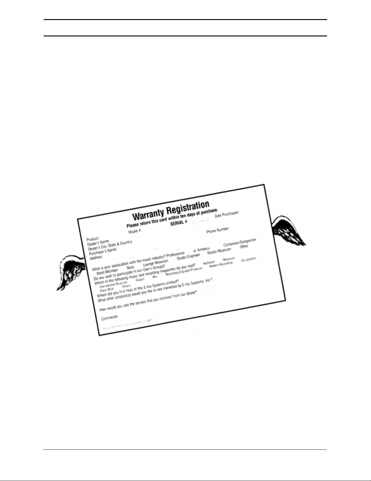
SEND IN YOUR WARRANTY CARD NOW!
It is vital that you send in your warranty card so that we can notify you of enhancements, new
features, and (nobody’s perfect) software bugs & cures. Sending in the warranty card also
entitles you to a free one-year subscription to “The Emu-Letter”, a bi-monthly company bulletin
carried in Electronic Musician (formerly Polyphony) magazine. You also become a part of the
Emulator II Users Group, your passport to the near- legendary annual parties where (among
other things) Emulator II owners swap disks, gossip, and tips.
But none of these wonderful things will happen to you unless you send in your warranty card.
Don’t miss out: Send it in now!
© 1985, 1986, 1987 E-mu Systems, Inc. Page 14
Page 15

INTRODUCTION
INSTANT GRATIFICATION!
If you just can’t wait another second before hearing the Emulator II, we understand. Follow the
directions below EXACTLY as given and get ready to hear some great sounds. (Incidentally, in
case you make a mistake or run into problems, don’t worry. This process is described in greater
detail in Guided Tour #1.)
1. Making sure that the Emulator II is unplugged; patch the rear panel MIX OUT jack to the
input of a high quality amplification system.
2. Turn the front panel MIX OUT volume control (located near the Emulator II logo) fully
counter-clockwise.
3. Check that the rear panel voltage selector is set for the correct voltage in your part of the
world.
4. Plug the Emulator II line cord into an AC outlet.
5. If you are not familiar with how to handle computer disks, you will have to delay your Instant
Gratification somewhat. Please turn to the GENERAL INSTRUCTIONS section and read the
part labeled GENERAL INSTRUCTIONS 5 on proper disk handling. If you know how to treat
disks with the proper loving care, then proceed.
6. Check that there are no disks currently in the disk drive(s). If there are, or if the disk drives
contain cardboard packing materials, turn the drive latches to their counter-clockwise
positions (see Fig. GENINS-3 in the GENERAL INSTRUCTIONS section), remove the disks
or packing materials, and put them in a safe place.
7. Turn on power. All LED’s will flash for a moment, except for the disk drive LED’s which will
continue to flash. The display will say Insert Diskette.
8. Select one of the factory disks supplied with the Emulator II, and insert it label side ~ with
the label going in last into the top disk drive (or the only disk drive with a single-drive
Emulator). Fig. GENINS-4 in the GENERAL INSTRUCTIONS section shows how to insert a
disk. When the disk is seated in the drive, turn the disk drive latch clockwise until it is
pointing straight down. The drive LED will turn on steadily, and the display will start
communicating with you.
9. When the drive LED turns off, turn up the MIX OUT control and start playing the keyboard.
All right!! The display will show you the number (P followed by two digits) and name of the
sound you are playing. These sounds are called Presets, for reasons that will become clear
later.
10. Use the calculator-type keypad underneath the display to call up different Presets. Press a
two-digit number; start with 01 and play the keyboard for a while, then press 02 and play,
03, 04, etc. At some point you will run out of factory Presets, and the display will say NOT
FOUND.
If you want, vary the modulation wheels towards the left hand side of the keyboard. They
perform different functions with different Presets.
© 1985, 1986, 1987 E-mu Systems, Inc. Page 15
Page 16

INTRODUCTION
11. To try out Presets from other factory disks, open the latch, remove the existing disk, and
insert another factory disk. Close the latch. Now, find the portion of the front panel labeled
“DISK” (towards the lower-right hand corner). Press its switch, and its LED will light up. Now
press 1 on the keypad. The disk drive will start making noises, and you will be on your way
to loading another bunch of sounds into the Emulator II. When the drive LED goes out,
press the DISK switch once more, then start playing the keyboard and selecting more
Presets.
* * * * *
By now you should be pretty impressed, but there’s much more to come...so keep reading, and
you’ll find out all about it.
© 1985, 1986, 1987 E-mu Systems, Inc. Page 16
Page 17

INTRODUCTION
HOW TO USE THIS MANUAL
The Emulator II is not an instrument that can be mastered in a few days. Therefore, this manual
is organized so that you can take “guided tours” of different sections of the Emulator II and learn
at your own pace.
The manual comprises five major parts:
1. Definitions This section explains how the Emulator II organizes sounds. It’s not exactly
easy reading, but pay close attention - it lays vital groundwork for the rest of the manual.
2. Guided Tours This part describes several “guided tours” you can take through the
Emulator manual’s Reference Section to help learn the instrument’s operation. Each tour
gives any necessary background information, and then directs you to particular parts of
the Reference Section where concepts are further developed. By following these tours in
the order presented, subjects are introduced logically and build on previously introduced
material.
3. Reference Section This is the heart of the manual, and describes every function
available on the Emulator II.
4. Advanced Applications (the Art of Sampling, MIDI and SMPTE supplements)
This includes information on how to get the most out of the Emulator II.
5. Appendix If you’re not sure what a VCF is, or what Q really means, relax...the answers
are here. Whenever you see a technical word or abbreviation that you don’t know, check
this section for the definition.
Caution: Much of the manual presents material as a series of steps. Always read to the end of
each numbered step before pushing any buttons! Sometimes a step presents several
alternatives, and tells you which one to choose at the end.
© 1985, 1986, 1987 E-mu Systems, Inc. Page 17
Page 18
INTRODUCTION
DEFINITIONS: HOW THE EMULATOR II ORGANIZES SOUND
Forget everything you’ve ever learned about voices, presets, and channels: The Emulator II
does things differently from traditional keyboard instruments.
Sampling Basics
The Emulator II is conceptually like a tape recorder in that it records sound. However, the
recording process is very different since the Emulator II is recording into computer memory.
Computers can accept information only in the form of numbers, so the Emulator converts audio
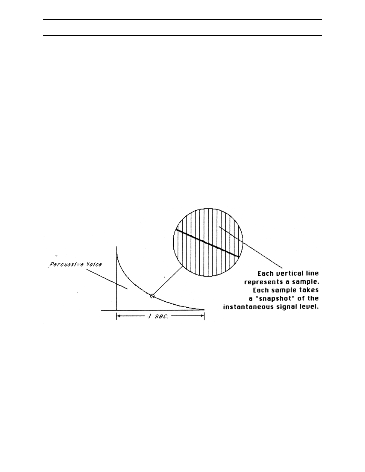
signals into numbers. It does this by examining (sampling) the incoming signal level 27,500
times a second, and sequentially recording these different levels in computer memory.
Figure 1 shows a one-second percussive sound being sampled. The magnified view shows
how the samples define the instantaneous level of the signal. Once stored in the Emulator II’s
memory bank, these samples may be played back (in the proper sequence, of course) to
reconstruct the original signal. If a two second sound was being sampled, it would require
2x 27,500 or 55,000 samples. Shorter sounds require fewer samples.
Figure 1
Just like tape, a sound can be manipulated once it has been recorded. Playing back, the
samples in the reverse order from which they were stored plays the sound backwards. Playing
back the samples at a faster rate than the rate at which they were stored raises pitch; playing
back at a slower rate lowers pitch (like a tape recorder’s variable speed control).
© 1985, 1986, 1987 E-mu Systems, Inc. Page 18
Page 19

INTRODUCTION
The Emulator II “Map”
Sure, you’re anxious to start coaxing wonderful sounds from the instrument -- but like ground
school for pilots, the following is a necessary part of learning how to play the Emulator II. It is
important to understand how the Emulator II organizes sounds in order to make best use of the
instrument in the shortest possible time. Also, many terms will be introduced now that will show
up later in the manual.
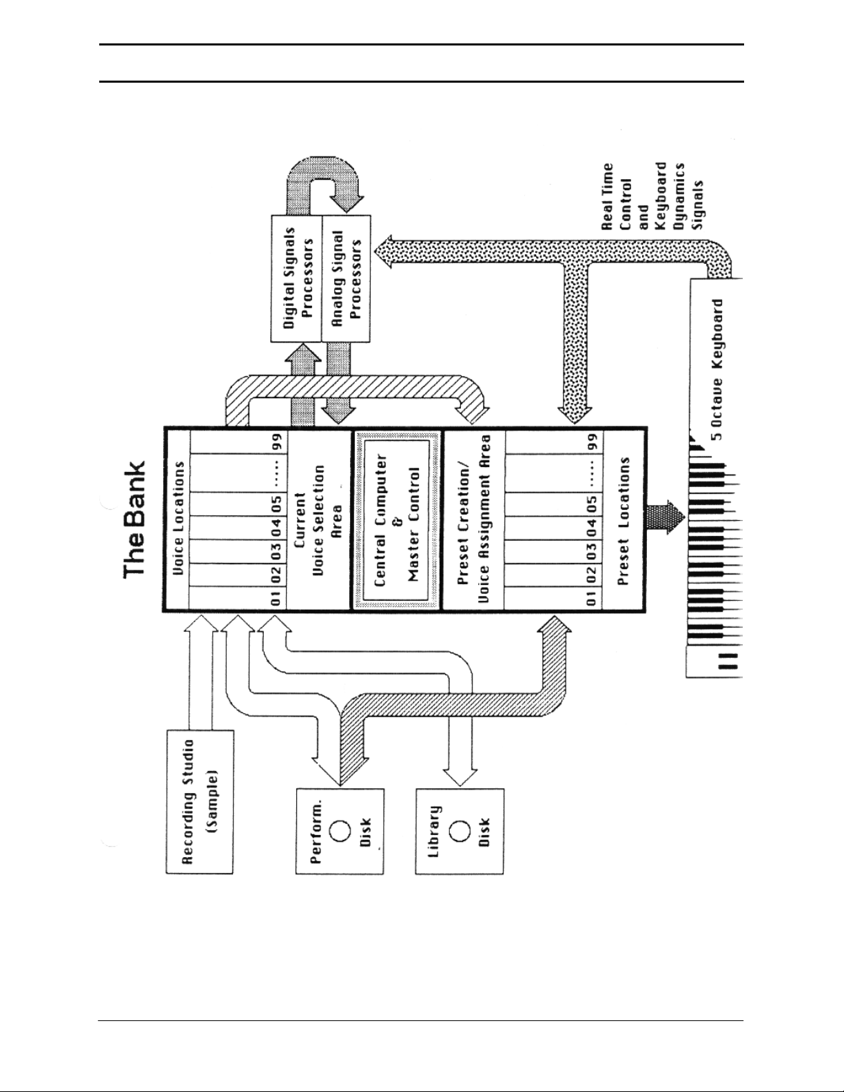
You can think of the Emulator II as resembling a collection of modules, linked by various
pathways (see the Map in Figure 2). These paths indicate how information flows within the
Emulator II; let’s take a closer look at what makes up this information, and how it is transferred
from one section of the instrument to another.
© 1985, 1986, 1987 E-mu Systems, Inc. Page 19
Page 20
INTRODUCTION
© 1985, 1986, 1987 E-mu Systems, Inc. Page 20
Page 21

INTRODUCTION
The Bank
The Bank contains all of the Emulator II’s memory (where, among other things, the sounds are
recorded), plus a high-performance Central Computer. The Bank is the central storehouse for all
of the Emulator II’s data. Although the memory is volatile, meaning that the data disappears
when you turn off power, the Bank data can be saved permanently on disk to keep a record of
your work. (This process is somewhat like saving the data in a regular polyphonic synthesizer to
cassette, but using disks results in far more efficient operation.)
Also note that because the memory is volatile, when you first turn on the Emulator II there’s
nothing in the Bank. Before you can make any sounds, data must be loaded into the Bank from
disk or by sampling sounds.
Since we now have a place to store information temporarily (the Bank), and a way to store
information permanently (saving to disk), let’s take a look at the different kinds of information
being stored.
The Voice
Sampling a sound using the instrument’s “Recording Studio” capabilities (upper left-hand block)
creates what the Emulator II calls a Voice, the “raw material” with which the instrument works.
(Voices can also be loaded in the Bank from disks, as described later.) This Voice could be a
sampled drum sound, violin note, jet plane, zither, oboe, steam press, or whatever. And if
having the entire world, as a potential sound source isn’t enough for you, the Emulator II can
also process Voices in a wide variety of ways (as we’ll discuss in “Voice Processing”).
The Bank can store up to 99 Voices, each with its own two-digit Voice number and name (i.e.
V21 Grand Piano). The total available sampling time is 17.6 seconds (484,000 samples); the
Bank Voices can divide up the 17.6 seconds any way you like (i.e. ten 1.76 second samples,
eighty-eight 200 millisecond samples, one 17.6 second sample, etc.).
A Voice can be assigned to a single note on the keyboard, but may be transposed
polyphonically to cover up to a two-octave range. The process of assigning, and optionally
transposing, Voices to specific ranges of the keyboard is called making a Preset. Note: It is
often necessary to use multiple Voices to make up a Preset, since wide-range transposition
alters the Voice’s timbre. Therefore, using multiple samples and transposing each over a small
range usually gives the most realistic sound.
The Preset
Making a Preset is a three-step process:
1. Give the Preset a number (i.e. P03) and name. The Bank can hold up to 99 Presets.
2. Assign the desired Bank Voices to different ranges of the keyboard (for example, with
five Voices you could assign each Voice to cover one octave of the keyboard.) This is
represented in Figure 2 by the path connecting the Voice Locations to the Preset
Creation/Voice Assignment Area. Note that the same Voice can be assigned to more
than one range of the keyboard in a given Preset, and also, Voices can be combined in
more than one way to make more than one Preset.
© 1985, 1986, 1987 E-mu Systems, Inc. Page 21
Page 22

INTRODUCTION
3. Choose from a number of options that further define the Preset, such as assigning
Voices to partially or fully overlap other Voices (thus producing doubling effects),
assigning dynamic control to individual Voices in a Preset, erasing Presets you don’t
like, cataloguing Presets, cataloguing the Bank Voices to see what’s available for
making up a Preset, adding arpeggiation, setting up MIDI parameters, etc.
Note that a Preset does not store the actual sounds that make up the Voices in the Preset;
rather, it stores data about the Voices (which ones to use, where they are assigned on the
keyboard, whether they should respond to keyboard dynamics, and the like). Because of this,
Presets do not take up as much Bank memory as Voices since data takes up less memory
space than sounds. (For an analogy, think of the cassette interface in a digital drum machine. In
just a few seconds, the cassette can record all of the patch data for the entire machine; it would
take far longer to record the actual sounds of all the drum machine patterns and sequences.)
OK...that’s the story on creating Voices and assigned them to the keyboard to make up a Preset
or Presets. Now let’s take a look at processing Voices.
Voice Processing
Once a Voice is loaded in the Bank and assigned to a Preset, it can be sent to the Analog and
Digital Processing modules. However, since (as mentioned earlier) a Preset typically contains
several Voices, we need to specify which Voice, or Voices, we want to process. This is called
selecting the Current Voice, another three-step process:
1. Call up a Preset that contains the Voice(s) to be processed.
2. Choose the Voice to be processed, or select several Voices and group them together so
that they are all processed simultaneously (this group of Voices is still referred to as the
“Current Voice”).
3. Send the Current Voice through the Analog and Digital Processing modules, whereupon
they return back to the Bank in their modified form. All Presets containing these Voices
will reflect the changes caused by processing.
The Current Preset
As you found out in the “Instant Gratification” section, as soon as a Performance disk is loaded
a Preset will be ready to go. This is the Current Preset. If you select another Preset, or create a
Preset, this becomes the Current Preset.
When you sample a sound to create a Voice, the Voice is automatically assigned to the two
lowest octaves (unless you specify otherwise) of the Current Preset. If the Bank was not empty
and you had a Preset selected, the sample will replace whatever sample was already in the
lowest two octaves of this Current Preset. (However, you do not over-write the Voice itself,
which stays safely tucked away in the Bank; you are simply over-writing the Voice assignment in
that particular Preset.)
If the Bank was empty prior to sampling (it’s generally best to clear the memory before
sampling; among other advantages, this allows for the maximum possible sampling time), the
Bank will automatically create a “NULL PRESET” into which it will assign the Voices that you
sample. Each successive Voice you sample will be assigned to the lowest two octaves of the
© 1985, 1986, 1987 E-mu Systems, Inc. Page 22
Page 23

INTRODUCTION
keyboard (unless you specify otherwise), and over-write the previous Voice assignment
(although as mentioned in the end of the last paragraph, the sampled Voices themselves remain
in memory).
The Disk Archives
So far, we’ve loaded a bunch of Voices into the Bank, created some Presets containing those
Voices, and done some Voice processing. However, remember that the Bank only retains this
information for as long as the Emulator II is plugged in and turned on. Of course, we don’t
expect you to leave the thing on all the time, which brings us to the subject of saving data on
disks.
There are two types of Emulator II disks, Performance disks and Library disks.
Commanding the Central Computer to “Save Bank” causes it to shuttle all the Bank data
(Voices, Presets, and Sequencer Sequences) on to a Performance disk. This disk permanently
stores data so that even after turning off the Emulator II. The disk will contain a record of your
work.
IF YOU DO NOT SAVE A BANK TO DISK, ALL BANK DATA WILL BE LOST WHEN YOU
TURN OFF THE EMULATOR II. Do not wait until the end of a session to save -- save your work
periodically in case of power failure or some other unforeseen circumstance which might erase
the Bank’s memory.
Since the Performance disk contains a record of the Bank data, loading the disk back into the
Bank transfers all the Voice, Preset, and Sequencer data into the Bank (this will replace the
existing Bank data, if any). Therefore, you can work a Bank of sounds out at leisure, and save
the results of your work on disk; when you go to a gig, simply take the Performance disk with
you and load all your hard work from disk into the Emulator II in a few seconds.
Library disks record and play back Voices only (unprocessed or processed), and contain no
Preset information. They are useful when building up a library of raw sounds. For example, you
might want to sample an instrument, but are unclear about what kind of Presets you want to
make up from these sampled Voices. Simply save the individual Voices to the Library disk, and
then load them into the Bank at a later date when you want to create some Presets. And, if
while creating the Preset you process the Voices too heavily and wish that you had the originals
back, no problem...they are still preserved on the Library disk.
Think of the Performance disk as something you take with you on gigs, and of the Library disk
as a means of storing a collection of raw sounds which can be used later on to make up
Performance disks. Note: With either disk type, if you pull a Voice or Preset from a disk, alter it,
and then save it to that same disk without changing its identifying number, the disk will erase the
original version and replace it with the processed version.
Incidentally, the process of having new data erase and replace old data is called over-writing.
© 1985, 1986, 1987 E-mu Systems, Inc. Page 23
Page 24

INTRODUCTION
The Keyboard
Note the two paths coming from the keyboard in Figure 2; the LFO, VCA, VCF, and ADSR
Analog Signal Processors are tied to keyboard dynamics (for example, playing harder can alter
the loudness, attack time, filter cutoff, etc.), as are some Preset assignment characteristics (i.e.
playing louder assigns a different Voice to a particular key).
The Output Channels
The Central Computer assigns keyboard keys to the output channels. When you play a key, that
key’s sound is assigned to Output Channel 1. If you hold this key and play another key, the new
key’s sound will be assigned to Output Channel 2. The Emulator II includes eight channels, so
you can play up to eight sounds simultaneously. Each channel has its own output jack, and
there is also a master output jack, which mixes the eight channels together. Individual Voices
can also be restricted to particular channels, which will be covered in detail later when we
discuss the Emulator II’s sequencer.
Re-cap
One more time: A Voice is a sampled sound. It is temporarily stored in the Emulator II’s Bank
and may be permanently stored on a Library disk. While a sampled Voice must be assigned to a
Preset prior to processing, a sampled Voice may nonetheless be processed immediately after
sampling since the Emulator automatically assigns the sampled Voice to a Preset it creates,
called the Null Preset.
To create a new Preset, make sure you have all the Voices required for the Preset in the Bank,
number and name a Preset, then assign combinations of Voices from the Bank to specific
sections of the keyboard. By specifying one or more of these Voices as the Current Voice, the
Current Voice may then be processed by the Emulator II’s analog and digital signal processors.
Since loading in a Performance disk fills the Bank with Voices and Presets, you can group these
Voices into new Presets, process the Voices, or alter the existing Presets.
Always Remember to Save Your Work
Once a Bank contains the desired Presets and Voices, it must be saved to a Performance disk.
Specific Voices can be saved to a Performance disk as part of a Bank, or saved individually to a
Library disk.
© 1985, 1986, 1987 E-mu Systems, Inc. Page 24
Page 25

INTRODUCTION
OTHER DEFINITIONS
Booting the Emulator II is not a repair technique; rather, it is a computer term that means
“putting a disk in the disk drive after you first turn it on, and having the computer read software
necessary for its operation from that disk”. (It’s easy to see why this was shortened to “booting”.)
To boot, insert a Performance or Library disk in the drive before, or just after, you turn on the
Emulator II. Closing the disk drive latch tells the Emulator to start reading the software. Once
booted, the instrument is ready to go. (Note: Booting from a Performance disk takes longer than
booting from a Library disk since after booting, the Emulator II loads the Performance disk Bank
data.)
A Default setting is what we’ve judged to be a useful initial setting, and remains in effect until
you change it. For example, the mic preamp in the sampling section defaults to zero gain when
you first turn on the Emulator II. Had it defaulted to the maximum gain position, this might have
blasted your ears off if you accidentally put in a line level signal, so we figured zero gain was
better.
The display’s cursor, a small line, will flash when it wants data from you about the number or
letter under which it is located. Entering a new value over-write the old one, whereupon the
cursor moves on to the next number or letter (if applicable).
Note: If the Emulator II is expecting a two or three-digit number, you must enter all the required
digits even if some of these are zeroes (called “leading zeroes”). For example, if the Emulator II
is expecting a three-digit number and you want to enter 8, you would enter 008. If it were
expecting a single-digit number, entering 8 would be sufficient.
Saving is the important process of saving your work to disk. Despite what computer
manufacturers would like you to believe, computers are not infallible and besides, the world
sometimes plays cruel tricks (like a power surge in the middle of a sampling session). To help
defy Murphy’s Law (“if anything can go wrong, it will”), whenever you have done enough work
on a Voice or Bank that you would hate to lose it, save it on at least one disk. Should you
improve the Voice or Bank later, you can always replace the original with the revised version -and if something goes wrong, the original will still be available to save you the hassle of starting
from scratch.
© 1985, 1986, 1987 E-mu Systems, Inc. Page 25
Page 26

THE GUIDED TOURS
THE GUIDED TOURS
© 1985, 1986, 1987 E-mu Systems, Inc. Page 26
Page 27

THE GUIDED TOURS
HOW TO USE THE GUIDED TOURS
Occasionally during a tour you will be told to refer to something like PRESET DEFINITION 11,
DISK 8, SAMPLE 2, or some other name. This means that you will find more information in the
specified section of the manual’s Reference Section. For example, PRESET DEFINITION 11
indicates that the information is in the Preset Definition chapter under section 11; DISK 2
indicates that the information is in the Disk chapter under section 2. Note that these chapters
are arranged in the same order as you encounter the Emulator II front panel “modules” if you
move from left to right along the top row of modules, then move from right to left along the lower
row of modules.
Figures are referred to by a shorthand name for the chapter and a number. For example, Fig.
GENINS-3 would be the third figure in the GENERAL INSTRUCTIONS chapter.
GETTING READY FOR THE GUIDED TOURS
Have you sent in your warranty card yet? Listen, we’re not kidding! Send it in!!
Okay. Now you can proceed.
1. Set up the Emulator II as described earlier under Instant Gratification. After completing
step 6, return to this section.
Remember - at this point playing the keyboard will not produce sound. In order to hear
anything, you must “load” a sound into the Emulator II from disk (which we’ll describe
shortly).
2. Make sure you have about a half-dozen 5.25” blank disks (double-sided/double-density,
48 TPI) on hand, plus a paper and pencil for taking notes.
© 1985, 1986, 1987 E-mu Systems, Inc. Page 27
Page 28

THE GUIDED TOURS
GUIDED TOUR #1: MEET THE EMULATOR
This tour covers how to:
Care for diskettes
Load a Bank from a Performance disk when first turning on power
Select different Presets from the Bank
Load additional Performance disks
Tune the Emulator II to other instruments
Transpose the keyboard
...and also discusses the Emulator II’s “modular” design philosophy.
DISK HANDLING
Disks are delicate and store valuable data. Before proceeding, carefully read GENERAL
INSTRUCTIONS 5 (“Disk Handling”) for important information on how to care for your disks.
LOADING A PERFORMANCE DISK
1. Turn on the Emulator II, then insert the Grand Piano disk in Drive 1 according to the
instructions given in the next to last section of GENERAL INSTRUCTIONS 5 (“Disk
Handling”).
2. After about 20 seconds of loading time, the display will show the Current Preset number
and name (the cursor will flash underneath the first digit). Start playing the keyboard and
turn up the MIX OUT control for a comfortable listening level.
SELECTING DIFFERENT PRESETS
1. The Bank you just loaded contains several Presets. To call up a new Current Preset, use
the keypad underneath the display. Note that “leading zeroes” must be entered for
Preset numbers (i.e. type 0 and 2, not just 2, to call up Preset 02). Now type 0 then 2 on
the keypad; these will replace the numbers indicated by the flashing cursor.
2. The display says P02 Piano #2. Play the keyboard...hey, it sounds just like a piano!
3. Now call up more Presets (refer to GENERAL INSTRUCTIONS 1, “Selecting the Current
Preset”), steps 1 and 2). If you make a mistake and enter a number for which there is no
Preset, the display will list the entered Preset number and say NOT FOUND; try calling
up the desired Preset again. To find out what Presets are available on the disk, refer to
PRESET DEFINITION 19, “Catalog Presets”.
When you’re ready to check out some more sounds, proceed.
© 1985, 1986, 1987 E-mu Systems, Inc. Page 28
Page 29

THE GUIDED TOURS
THE EMULATOR II’s “MODULAR” PHILOSOPHY
The Emulator II front panel is divided into modules. Each module will be discussed in detail later
on; the following is intended mostly as background information. Each module affects a certain
area of the Emulator II’s operation. Refer to the map (Fig. INTRO-2) to see how some of these
modules fit into the Emulator II’s overall structure.
Master Control. This includes controls that affect the entire keyboard (such as Tune, Volume,
and Transpose), a ten-digit calculator-like keypad with numbers printed above the keys, the
display, and four sliders, which set variable parameters (described later). Note that keypad
switch 7 doubles as a NO button and keypad switch 9 doubles as a YES button (sometimes the
Emulator II will ask you yes-no questions, and this is how to communicate with it).
Sequencer. This module is an eight-track solid state recorder with sophisticated features such
as SMPTE and MIDI control, punch-in and erase, track bounce, cue, and auto correct.
Filter. You can dynamically change the timbre of any Voice or group of Voices (in other words,
the Current Voice) via lowpass filtering. The filter features variable cutoff, variable Q, variable
envelope amount (normal or inverted), variable keyboard tracking, LFO modulation, and
includes its own ADSR envelope generator.
VCA/LFO. You may change the attack/decay/sustain/release characteristics of the Current
Voice by modulating the VCA with its associated ADSR envelope generator. This module also
sets most LFO parameters.
Voice Definition. With this powerful module, you may edit a Voice’s length, loop (e.g. infinitely
sustain) any portion of the Voice (with several different looping options), have the Emulator II
automatically find the best loop points (“AutoLoop”), adjust the relative mix of various Voices,
save Voices to disk, and perform other Voice-related operations. This module also sets
independent keyboard touch sensitivity for each of several filter and VCA destinations
(dynamics, cutoff frequency, Q, attack time) and programs the mix (audio balance) for each
individual Voice in the Preset.
After modifying Voices, don’t forget chat the only way to keep these modifications is to save
them to disk. Otherwise, any changes will be lost as soon as power to the Emulator II is
interrupted.
Preset Definition Does all the “housekeeping” for the Emulator II: You may name Voices or
Presets, erase them, copy them, assign Voices to different places on the keyboard, “catalog”
the names of Voices and Presets stored in the Bank, etc. Other Preset Definition functions
include MIDI and arpeggiator selection as well as three keyboard-related special effects
(velocity switch, velocity crossfade, and positional crossfade).
Sample. This “recording studio” module records sounds from the outside world into the Bank.
Features include adjustable preamp gain, variable threshold setting, and adjustable sample
length.
Disk. The DISK module archival data traffic between the Emulator II and its disks. Sounds may
be stored on disk, read back from disk, catalogued, and more.
© 1985, 1986, 1987 E-mu Systems, Inc. Page 29
Page 30

THE GUIDED TOURS
Special. This module mostly contains test routines. However, because of its computer-based
nature, the Emulator II can be updated easily. This module will also access any new functions
dreamed up by the wizards at E-mu. Calling up its Catalog will tell you what special functions
are present.
Real-Time Control. This assigns different destinations (pitch, filter cutoff, VCA attack, etc.) to
your choice of the two modulation wheels (located at the left of the keyboard), foot pedal, three
MIDI control channels, and dual programmable footswitches.
Enter. Just as you can activate a module to tell the Emulator II something you want to do, the
Emulator II can activate this module when it wants to signal ~ to do something. It communicates
in one of two ways: by flashing the ENTER light, or turning it on steadily. The significance of the
two states will be explained later.
ACTIVATING and DE-ACTIVATING MODULES, SELECTING FUNCTIONS
Here’s important background information on how to access the various module functions. In the
next section of this tour, we’ll relate this information to a practical example.
Activating: Each module, except for Master Control and Sequencer, includes a switch and
accompanying LED. Pushing this switch “activates” the module, as indicated by the LED lighting
up. (Note: There must be a disk in the drive when you activate any module; the disk drive may
run for a second or two before the module LED lights up.) The display’s top line will give a
Module Identifier (such as “VCA/LFO”, “Disk”, “VoiceDef”, or the like), followed by the range of
possible numbers you may enter to call up various module functions (see below).
Selecting functions: Each module includes a printed list of functions on the front panel; these
functions are available when the module is active. Selecting a module function requires keying
in its associated number with the keypad. We will shortly give an example of how this all works.
De-activating: When you’re finished with the module either press its button again to deactivate, or simply activate a new module.
Hint: Any time you make a mistake, get confused, or otherwise get “lost in the module” and
need to bail out, simply de-activate the module. Then, re-activate and try again.
LOADING OTHER PERFORMANCE DISKS
So far, so good...now it’s time to move on from the piano. The following instructions are for a
dual-drive Emulator II; see the end of this section for single-drive Emulator II instructions.
1. Select the Performance disk of your choice and insert it into the disk drive of your
choice.
2. If the Performance disk was inserted in Drive 1, refer to DISK 1. (“Get Bank Disk 1”). If
the Performance disk was inserted in Drive 2, refer to DISK 2 (“Get Bank Disk 2”)
instead. After following the directions in the indicated section, return to this section.
© 1985, 1986, 1987 E-mu Systems, Inc. Page 30
Page 31

THE GUIDED TOURS
Note: You can have different Performance disks in both drives, and load a Bank from either disk
(but not both simultaneously) by using the appropriate command (GET BANK DISK 1 or GET
BANK DISK 2). Loading in a new Bank will erase any currently loaded Bank.
Loading instructions for single-drive Emulator II:
1. Remove the old Performance disk from Drive 1, then insert and latch the new
Performance disk into Drive 1.
2. Refer to DISK 1 (“Get Bank Disk 1”), follow the instructions, and then return to this
section.
TUNING THE EMULATOR II TO OTHER INSTRUMENTS
Refer to MASTER CONTROL - TUNE. This function demonstrates how the Emulator II uses the
slide controls to set parameters. In this case, only one of the four sliders is used. However,
when setting such parameters as ADSR values for the filter or VCA, all four sliders are used.
TRANSPOSING THE KEYBOARD
Refer to MASTER CONTROL - TRANSPOSE.
FORMATTING DISKS
Format an equal number of Performance and Library disks (at least two of each) according to
the instructions given in DISK 8, “Formatting a Performance or Library Disk”. These will come in
handy during future guided tours.
© 1985, 1986, 1987 E-mu Systems, Inc. Page 31
Page 32

THE GUIDED TOURS
GUIDED TOUR #2: SPECIFYING THE “CURRENT VOICE”
BACKGROUND
The Emulator II has three main Voice processing modules:
1. Filter varies a Voice’s harmonic content via a four pole, low pass filter and associated
ADSR envelope generator.
2. VCA/LFO varies the Voice’s LFO parameters as well as the amplitude attack, decay,
sustain, and release characteristics.
3. Voice Definition provides sophisticated digital processing and also sets the keyboard
dynamics.
Each Voice stored in a Bank can have its own individual Filter, VCA/LFO, and Voice Definition
settings. Therefore, we need a way to specify the Current Voice, which is the individual Voice
(or collection of individual Voices) to be processed.
The concept of the Current Voice is important. To process one Voice out of a Preset, assign the
Current Voice to be that one Voice, and process it. To process more than one Voice at a time,
specify a group of Voices to be the Current Voice and process all Voices simultaneously.’
This section covers how to identify which keyboard keys belong to which Voice, and how to
specify which Voice or Voices make up the Current Voice. For a short form version of this tour,
see GENERAL INSTRUCTIONS 2 (“Assigning the Current Voice”).
To begin, if the Grand Piano Performance disk described in Guided Tour #1 has not been
loaded, load it from Drive 1 and select Preset 01. Also, read ENTER (the last chapter in the
Reference Section) on the function of the ENTER button, as it will be used during this and most
subsequent tours.
IDENTIFYING WHICH KEYBOARD KEYS BELONG TO WHICH VOICE
Once the Emulator II Bank has sounds in it, activate the Filter, VCA/LFO, or Voice Definition
module; its LED will light. If a Voice has not been previously selected, the display will say:
No Current Voice
Play a Key
If so, move on to step 2. If a Current Voice has been previously assigned, the display’s
top line will give the Module Identifier. The bottom line will give the Voice number (V
followed by two digits), and the Voice name (such as PIANO A.2). If this is the
© 1985, 1986, 1987 E-mu Systems, Inc. Page 32
Page 33

THE GUIDED TOURS
case, before proceeding, to step 2 initiate the CHANGE CURRENT VOICE function by
keying in 00 if the Voice Definition module is active, or 0 if the Filter or VCA/LFO module
is active.
Note: We hereby formally apologize that the Voice Definition CHANGE CURRENT
VOICE function (00) is not printed on the front panel label. This is because we had the
labels printed up before the function was implemented, and since we have over 1,000
pricey custom labels sitting in the warehouse and we aren’t about to throw them
out...well, you get the picture.
1. Play a key. The display’s top line will now give the Voice number and name of the Voice
assigned to that key; the bottom line will most likely say “Play a Key”. The ENTER LED
will be flashing.
Example: Play a note in the lowest octave, and the display identifies the Voice...
V01 Piano A1*
Play a Key
* or possibly A2
If the bottom line reads “Again2nd Voice” instead of “Play a Key”, it means that another
Voice overlaps (“doubles”) this key. Press the same key again; the display’s top line will
show the overlapping Voice, and the bottom line will say Again=2nd Voice.
2. Play different keys, one at a time, over the full range of the keyboard. The display will
give the Voice number and name to which each key belongs, and (if appropriate)
indicate when it is being doubled by another Voice. Take a minute or two and note
where the various Voices begin and end, and which Voices are at which locations on the
keyboard.
Hint: Most Emulator II owners list the pitch of the originally sampled note with a Voice
name. In the previous example, Voice 01 was a piano note originally sampled at pitch of
A, lowest octave (A1). Octaves are referenced so that the left-most octave spans C1-B1,
the next octave to the right C2-B2, and so on until the right-most octave spans C5-C6.
(Note: Early Grand Piano disks have the octave numbers offset by one. These disks are
identical to newer versions in all other respects.)
3. When the display shows the Voice (or one of the Voices) to be processed, press
ENTER. For now, choose any Voice and press ENTER; this Voice has now been
assigned as the Current Voice.
© 1985, 1986, 1987 E-mu Systems, Inc. Page 33
Page 34

THE GUIDED TOURS
4. The display now asks:
V01 Piano A1*
Addl Voices? Y/N
* or Voice to be modified
There are two possible choices. To make this single Voice the Current Voice, press NO
to tell the Emulator II you want no additional Voices; when you select a processing
module, it will process only this Voice. To specify additional Voices as part of the Current
Voice, press YES. For now, press YES to see how this process works.
5. The display asks:
V01 Piano A1*
Entire Kybd? Y/N
* or Voice to be modified
To assign all Voices on the keyboard as the Current Voice, press YES; when you select
a processing module, it will affect all Voices on the keyboard simultaneously. To assign
additional Voices (but not the entire keyboard) as the Current Voice, press NO. For now,
press NO.
6. The display asks:
V01 Piano A1*
Play Addl Voice
* Voice numbers you just assigned
As you play additional Voices, a new Voice number and name will appear on the
display’s top line, while the bottom line says Play a Key. Play various keys; when the
display shows a Voice you want to modify, press ENTER to make it part of the Current
Voice. Before proceeding to the next step, choose a Voice and press ENTER.
7. The display now updates the Current Voice listing (top line) by displaying both of the
Voice numbers chosen for processing, while the bottom line says Play Addl Voice.
Continue playing additional Voices and pressing ENTER until you have assigned all of
the Voices that make up the Current Voice (for now, assign one more Voice). To finish
the Current Voice assignment, press ENTER once more.
Note: If you assign more than five Voices as the Current Voice, the display will list the
first five Voices assigned. An additional + symbol indicates there are more Voices
assigned than the display can list.
© 1985, 1986, 1987 E-mu Systems, Inc. Page 34
Page 35

THE GUIDED TOURS
8. If all is well, the display should look something like:
Module Identifier
XX*
* Voice numbers you just assigned
9. The assigned Current Voice will remain as is until you change the Current Voice
assignment, change Presets, or load another Bank. If you switch between modules, the
Current Voice remains as assigned.
To change the Current Voice, initiate the CHANGE CURRENT VOICE function by keying in
00 for the Voice Definition module (see VOICE DEFINITION 00) or 0 for the Filter or
VCA/LFO module (see FILTER 0 or VCA/LFO 0 respectively), then return to step 2.
Now that you know what a Current Voice is all about and how to specify it, we’ve reached
the end of this tour (although you may need to come back from time to time to refresh your
memory). In the next tour, we’ll see how to modify Voices with the VCF and VCA/LFO.
© 1985, 1986, 1987 E-mu Systems, Inc. Page 35
Page 36

THE GUIDED TOURS
GUIDED TOUR #3: THE FILTER and VCA/LFO MODULE
BACKGROUND
The filter module contains eight 24dB/octave low pass filters (one per channel) that vary a
sound’s high frequency content.
The VCA/LFO module contains eight VCA’s that control a sound’s amplitude envelope, and
eight LFO’s that provide modulation to the filters or VCA’s.
We suggest loading in the synthesizer disk and selecting Preset 01 (arpeggiated bass/synth) to
most clearly hear the filter and VCA/LFO effects, however, any other sustaining sound (strings,
piano, etc.) is acceptable. We will cover the filter module first, and then proceed to the VCA/LFO
module.
SPECIFYING THE CURRENT VOICE
1. Activate the Filter module (if it is not already) by pushing its button.
2. Assign the Current Voice according to the instructions given in GENERAL
INSTRUCTIONS2 (“Assigning the Current Voice”); the filter will affect this Voice or these
Voices. If you loaded the synthesizer disk, you may process the entire synthesizer by
specifying Vl6, V17, V18, and V19 as the Current Voice.
To specify a different Current Voice, refer to FILTER 0.
FILTER FUNCTION 1: CHANGING CUTOFF FREQUENCY, Q, and ENVELOPE
1. After specifying the Current Voice, the display will give the Module Identifier in the top
line and list the assigned Voices in the bottom line.
2. Now follow the instructions in FILTER 1 (“Frequency, Q, Envelope Amount”). When it
describes how sliders A, B, and C affect the sound, vary these sliders while playing the
keyboard to hear the results.
Important note: Any slider setting change will not affect the note(s) being held down
(except with the Master Tune function); you must hit a new note or re-trigger the same
one to hear any effect.
Since we do not yet want to exit this function, after reading step 1 in FILTER I return to
this section starting with step 3.
3. After playing with the three sliders, before proceeding to the next section set Freq to
000, Q to 50, and Env to +40. Then exit the function by pressing ENTER (as described
in GENERAL
© 1985, 1986, 1987 E-mu Systems, Inc. Page 36
Page 37

THE GUIDED TOURS
FILTER FUNCTION 2: LFO AMOUNT AND KEYBOARD TRACKING
1. Follow the instructions in FILTER 2. When it describes how sliders A and B affect the
sound, vary these sliders while playing the keyboard to hear the results.
As mentioned previously, slider-setting changes will not affect the note(s) being held
down; you must hit a new note to hear any effect.
Since we do not yet want to exit this function, after reading step 1 in FILTER 2 return to
this section starting with step 2.
2. After playing with the two sliders, before proceeding to the next section set LFO Amt to
00 and KBD Amt to 1.00, then exit the function by pressing ENTER (as described in
GENERAL INSTRUCTIONS 3, “Exiting a Function”).
FILTER FUNCTION 3: ADSR SETTINGS
1. Follow the instructions in FILTER 3; when it describes how sliders A, B, C, and D affect
the sound; vary these sliders while playing the keyboard to hear the results. Remember,
slider setting changes will not affect the note(s) being held down so you must hit a new
note to hear any effect. (Since you’ve probably figured this out after all our repeated
warnings, from now on we’ll give you a break and not mention the bit about having to hit
new notes anymore.)
Since we do not yet want to exit this function, after reading step 1 in FILTER 3 return to
this section starting with step 2.
2. After playing with the four sliders, before proceeding to the next section set Atk = 01,
Dec 01, Sus = 32, and Rel = 32. This opens up the filter all the way, and makes it easier
to observe the effects of changing the VCA settings. Exit the function by pressing
ENTER to return to the Module Identifier, or even more conveniently, go directly to the
VCA/LFO module by activating it (as described in GENERAL INSTRUCTIONS 3,
“Exiting the Function”).
Since you have no doubt figured out how to Exit a Function by now, we’ll stop putting in
all these references to GENERAL INSTRUCTIONS 3.
© 1985, 1986, 1987 E-mu Systems, Inc. Page 37
Page 38

THE GUIDED TOURS
VCA/LFO FUNCTION 1: ADSR SETTINGS
1. Assuming that you have the same Current Voice as specified during the previous part of
the tour, the display’s top line will give the Module Identifier and the bottom line will list
the Voices that make up the Current Voice.
2. Follow the instructions in VCA/LFO 1; when it describes how sliders A, B, C, and D
affect the sound, vary these sliders while playing the keyboard to hear the results.
Since we do not yet want to exit this function, after reading step 1 in VCA/LFO 2 return
to this section starting with step 3.
3. After playing with the four sliders, before proceeding to the next section set Atk = 01,
Dec = 01, Sus = 30, and Rel = 30 and press ENTER to exit the function. Entering these
values lets the VCA stay open long enough to easily observe the effects of changing the
LFO settings.
VCA/LFO FUNCTION 2: LFO SETTINGS
1. Follow the instructions in VCA/LFO 2, but before playing with any of the sliders, move
Slider D up to maximum. This gives maximum VCA modulation, thus making it easier to
hear the effects of varying sliders A-C. As you vary these three sliders, play the
keyboard to hear the results, and then experiment with slider D. The Emulator II’s sine
wave LFO is typically used to add vibrato.
Since we do not yet want to exit this function, after reading step 1 in section VCA/LFO 2
return to this section starting with step 2.
2. After playing with the four sliders, this might be a good time to experiment some more
with the Filter and VCA/LFO module settings. Or, de-activate VCA/LFO, load in a new
disk, and then experiment with the Filter and VCA/LFO controls. Whatever, have a good
time and when you want to find out how to use the keyboard dynamics and get into realtime modulation control, proceed to the next tour.
© 1985, 1986, 1987 E-mu Systems, Inc. Page 38
Page 39

THE GUIDED TOURS
GUIDED TOUR #4: REAL TIME CONTROL and VIBRATO DEPTH
BACKGROUND
Ever wanted to add vibrato to a grand piano? Or bend its pitch? The Real Time Control module
can do this, and lots more. Incidentally, for future reference GENERAL INSTRUCTIONS 6
(“Selecting Real Time Control Functions”) contains a short form version of the material
presented in the first part of this tour.
Note: The Emulator II offers two vibrato functions: Pre-programmed (which adds a constant,
selectable amount of vibrato), and Real-time (where the player adds in vibrato by using one of
the modulation wheels). These two are mutually exclusive; if you specify real-time vibrato, the
pre-programmed vibrato will become inactive and vice-versa.
To make “live” playing as simple as possible, the display works somewhat differently for this
module. Load in the disk of your choice (preferably with fairly long and sustained sounds), then
activate the Real Time Control module. The display shows eight pairs of numbers:
1:0 2:0 3:0 4:0
5:0 6:0 7:0 8:0
The first number of each pair stands for one of the eight possible control sources (the left-hand
column of functions printed in the module), namely:
1. Left modulation wheel (center detent, spring return type)
2. Right modulation wheel (continuously variable type)
3. Control voltage pedal (plugs into rear panel PEDAL A/D jack; also accepts any 0 to +10V
control voltage source)
4. MIDI control channel A
5. MIDI control channel B
6. MIDI control channel C
7. Footswitch 1 (plugs into rear panel FOOT SW1 jack)
8. Footswitch 2 (plugs into rear panel FOOT SW2 jack)
The second number of the pair represents a control destination (the right-hand column of
functions printed in the module) that you assign to a control source.
Each of the destinations printed in the upper right-hand column (0 - 7) can be controlled by
control source 1, 2, or 3 or via data sent through any of the three MIDI control channels. Each
destination can be controlled by only a single source; assigning a destination to another source
de-assigns it from the previous source to which it was assigned.
© 1985, 1986, 1987 E-mu Systems, Inc. Page 39
Page 40

THE GUIDED TOURS
MIDI Controls 4,5 and 6 are described more fully in PRESET DEFINITION 30, “MIDI Setup”,
and in the Advanced Applications section of this manual.
Each of the destinations printed in the lower right-hand column (0 - 5) can be controlled by
sources 7 and 8. Each destination can be controlled only by a single source.
You’ll be happy to know that Realtime control settings are memorized for each Preset. Thus, if
desired each Preset can react to the real time controls and MIDI control channels in different
ways.
Note: Real-time functions usually control all Voices on the keyboard. However, when making up
a Preset, it is possible to exempt individual Voices from real-time control. This is described fully
in VOICE DEFINITION 29 (“Control Enable”).
SELECTING A CONTROL SOURCE and CONTROL DESTINATION
1. With the Real Time Control module activated, select a control source (wheel, pedal, or
footswitch) by keying in its associated number. For now, enter 1 for Left wheel; the
cursor will flash underneath the number to the right of the chosen control source
number, thus indicating that the Emulator II is ready for you to key in the control source’s
destination.
2. Enter the desired destination number. For now, enter 1 so that the previously chosen
Left wheel controls pitch. The flashing cursor will disappear and you will now be able to
select another control source if desired. (If a control source has been previously
assigned, the old assignment will be replaced with the new one.)
3. Experiment with using the Left Wheel to bend pitch, and then proceed.
REAL TIME FUNCTIONS
To learn about the real time functions, refer to the REAL TIME CONTROL section in the
Reference Section. Practice assigning various destinations to the two wheels and to the
footpedal (sources 1, 2, and 3 respectively).
Note: When assigning the footpedal, make sure it’s plugged in to prevent unpredictable results.
Before experimenting with the footswitches (sources 7 and 8), we need to understand the
difference between looped and unlooped sounds. Looping is described more fully in VOICE
DEFINITION 12 and VOICE DEFINITION 13, but basically, a looped sound is one where a
portion of the sound is put into an “infinite repeat” loop for as long as you hold down the key.
This is similar to the infinite repeat function on digital delay lines. Looping allows for sustaining a
normally non-sustaining sound for as long as you like. An unlooped sound is not artificially
sustained, and therefore lasts its normal length.
Keeping this in mind, refer to REAL TIME (FOOTSWITCH DESTINATION) O through REAL
TIME (FOOTSWITCH DESTINATION) 5 and assign various functions to the footswitches. Note
© 1985, 1986, 1987 E-mu Systems, Inc. Page 40
Page 41

THE GUIDED TOURS
that some sounds lend themselves to these functions better than other sounds, so feel free to
experiment with loading different disks to experience the full range of real time control options.
PROGRAMMING VIBRATO DEPTH
While real time control is invaluable for such applications as adding expressiveness to solo
lines, for those times when you want to add a pre-programmed (constant amount) of vibrato (i.e.
adding vibrato to something like a string section, preferably using vibrato delay and variation
effects described later in this manual), refer to VOICE DEFINITION 23 (“Vibrato Depth”).
© 1985, 1986, 1987 E-mu Systems, Inc. Page 41
Page 42

THE GUIDED TOURS
GUIDED TOUR #5: THE DYNAMIC KEYBOARD
BACKGROUND
The Emulator II not only delivers polyphonic dynamics, but for maximum expressiveness also
allows for dynamic control over several other parameters.
The following steps set up the synthesizer sound so that any changes in dynamics are very
noticeable.
1. Load the bass/synthesizer Factory Disk into the Emulator II (see section DISK 1 and
DISK 2, “Get Bank from Disk”), and specify Preset 01 (arpeggiated bass/synth).
2. Activate the filter module, and specify Voices V16, V17, V18, and V19 (the synthesizer
Voices) as the Current Voice; then call up FILTER 1 and set Freql2O, Q30, and Env
+00.
3. Activate the VCA/LFO module and select VCA/LFO 1. Set AtkOl, DecOl, Sus=32, and
Rel15.
ASSIGNING KEYBOARD VELOCITY TO DYNAMICS
1. Activate the Voice Definition module. Voices V16 - V19 should make up the Current
Voice; if not, key in 00 to change the Voice assignment and assign these Voices (see
GENERAL INSTRUCTIONS 2, “Assigning the Current Voice”).
2. Follow the instructions in VOICE DEFINITION 21 and play the keyboard. Note how
varying Slider A varies the overall dynamics, while varying Slider B controls how the
attack time is affected by how you play the keyboard.
3. Since we do not yet want to exit this function, after reading step 1 in VOICE DEFINITION
21 proceed to VOICE DEFINITION 22 on assigning keyboard velocity to filter
parameters.
4. ‘When you reach step 2 in VOICE DEFINITION 22, congratulations! By this point in the
Guided Tours, you have learned the rudiments of loading and modifying sounds.
Proceed to the next section -- the one you’ve been waiting for -- on how to sample.
© 1985, 1986, 1987 E-mu Systems, Inc. Page 42
Page 43

THE GUIDED TOURS
GUIDED TOUR #6: BASIC SAMPLING
Sampling does not just involve sticking a microphone in front of something; sampling is an art.
As a result, we’ve devoted a whole section to the art of sampling in the Advanced Applications
section of this manual. Meanwhile, this Guided Tour gives you the basics, and also lays the
groundwork for guided tours of the Voice Definition and Preset Definition modules.
SETUP
1. Plug a microphone into the rear panel SAMPLE IN jack (an instrument can also be used,
but a mic is easier to work with for now).
2. Format a Performance or Library disk (see DISK 8, “Format Disk”), then insert and latch
it into Drive 1. The maximum available sampling time (with nothing stored in memory) is
17.6 seconds; sampling reduces this memory until all 17.6 seconds are used up. To free
up as much sampling space as possible, clear out the existing memory just before
sampling (to clear memory, refer to PRESET DEFINITION 16, “Erase Bank”, then
return). The 17.6 seconds can be divided any way you want -- one long sample, or
several shorter samples. To monitor how much memory is left, refer to PRESET
DEFINITION 20 (“Memory Remaining”).
3. Now it’s time to start the sampling process. Begin by setting levels as described in
SAMPLE 1 (“VU Mode”) and SAMPLE 3 (“Gain Set”), then set the threshold as
described in SAMPLE 4 (“Threshold Set”).
4. The Emulator II default assignment places the original sampled sound on key C2, and
transposes it across the range from C1 to C3. Leave this as is for now (to change this
default assignment, see SAMPLE 2, “Define Voice”).
5. Once the levels, threshold, and assignment are set, begin sampling (see SAMPLE 7,
“Arm Sampling”). Either sample the entire 17.6 seconds, or press 0 to stop sampling. Do
not deactivate the module after the sample is complete.
6. Play the keyboard in the assigned range to hear the results of your sampling.
7. Now experiment with more sampling: Try setting a particular sample length (SAMPLE 5),
using forced sampling instead of threshold-sensitive sampling (SAMPLE 9), assigning
the sampled sound to other portions of the keyboard (SAMPLE 2), and also, practice
terminating the sampling process (SAMPLE 0). As long as you do not de-activate the
module, new samples will replace previous samples.
8. To save a Voice in memory and move on to sampling another Voice, de-activate the
Sample module. The previously sampled Voice, identified with the Voice number
assigned during SAMPLE 2 (“Define Voice”), will be saved in memory. Upon activating
the sample module, either the top line of the display will give a number for the new Voice
to be sampled, or the bottom line will say NEED MORE ROOM. The latter doesn’t mean
that the Emulator II is getting claustrophobic, but rather, that you’ve used up all the
memory on previous samples. To continue experimenting, first save anything you need
to save on disk (see DISK 7, “Save Bank” and VOICE DEFINITION 30, “Save Voice to
© 1985, 1986, 1987 E-mu Systems, Inc. Page 43
Page 44

THE GUIDED TOURS
Disk”), and then create additional room by erasing all memory (see PRESET
DEFINITION 16, “Erase Bank”).
9. Remember, this Guided Tour is intended simply as an overview to give you a “feel” for
the sampling process. Later on, we will learn how to organize these Voices in a
musically useful way.
© 1985, 1986, 1987 E-mu Systems, Inc. Page 44
Page 45

THE GUIDED TOURS
GUIDED TOUR #7: DIGITALLY PROCESSING SAMPLES
Digital processing allows for radically altering Voices stored in the Bank. In this Guided Tour,
we’ll learn -- among other topics -- how to truncate, loop, reverse, splice, and mix samples. First,
though, we need to take a couple of samples with which we can practice.
1. If the Emulator II has been turned off, insert a formatted Performance or Library disk in
Drive 1 and boot the instrument. After booting, or if the instrument was already on, check
that there is nothing in memory you want to save. If there is, save it. If not, clear the
Bank memory by activating the Preset Definition module then pressing 16, YES, and
YES. Finally, deactivate the module.
2. Make a sample of yourself speaking some words by doing the following:
a. Plug a microphone into the SAMPLE INPUT jack.
b. Activate the sample module and turn up the sample module CAIN control.
c. Talk into the mic. If the display’s VU meter reads a low signal level, press 3 to
increase the gain. Move Slider A until the display shows an input gain of 40
dB, then press ENTER.
d. While continuing to talk into the mic, adjust GAIN for the strongest possible
VU meter signal short of overload.
e. Press 4 and use Slider A to set a threshold above the background noise
present at the mic. Then press ENTER.
f. Press 5 and use Slider A to select about a 3 second sampling time.
g. Press 7 to arm sampling, and begin talking. If the sample is not good or you
want to try again, press 7 and take another sample.
h. Play C2. You should hear your sample. Now play in the range of C1 through
C3 to hear the transposed sample.
i. If you’re not satisfied with the sample, erase it with PRESET DEFINITION 13
and try again. Once you’re satisfied with the sample, de-activate the sample
module. The sample you just recorded is Voice V01.
3. We will need a second sample of you talking, so...
j. Activate the sample module. Talk into the microphone to check for level; the
level should already be correctly set from the last sample. Note that the
sample module will remember the +40 dB preamp gain setting until you
change it or turn off the Emulator. If the level is not correct, repeat steps C
and D above.
k. Press 4 and use Slider A to set a threshold above the background noise
present at the mic. Then press ENTER.
l. Press 5 and use Slider A to select about a 3 second sampling time.
m. We want to assign this new sample to a different range of the keyboard, so
press 2.
n. Press C4 (this becomes the original pitch), then C3 (this sets the lowest
transposition from the original pitch), then C5 (this sets the highest
transposition from the original pitch).
© 1985, 1986, 1987 E-mu Systems, Inc. Page 45
Page 46

THE GUIDED TOURS
o. The display now identifies this Voice as NEW VOICE V02. If you want to call
it by a different number, you could do so by pressing the appropriate numbers
of the keypad; but for now, V02 is just fine. Press ENTER.
p. Press 7 to arm sampling, and begin talking. If the sample is not good or you
want to try again, press 7 and take another sample.
q. Play C4. You should hear your sample. Now play in the range of C3 through
C5 to hear the transposed sample. Note: The new sample’s lowest key, C3,
is the same as V01’s highest key. When sampling, if a new sample is
assigned to the same key range as an older sample, the new sample will
override the old sample.
r. If you’re not satisfied with the sample, erase it with PRESET DEFINITION 13
and try again. Once you’re satisfied with the sample, de-activate the sample
module. You now have two samples, V01 and V02.
PLAYING A VOICE BACKWARDS
1. You can play samples backwards as well as forwards. Activate the Voice Definition
module and refer to VOICE DEFINITION 27.
TRUNCATING A VOICE
1. Activate the Voice Definition module. Assign the first sample as the Current Voice by
playing a key in the range of C1 - B2, then pressing ENTER (for more details, see
GENERAL INSTRUCTIONS 2, “Assigning the Current Voice”). Truncating involves
cutting off the beginning or end of a sample; proceed to VOICE DEFINITION 11 and
adjust the sliders to hear how truncation works.
2. Practice truncating by isolating individual words from the sample. This will give you a feel
for the truncation process. This may seem difficult at first, but with practice, truncation
becomes second nature.
3. When you reach step 6 in VOICE DEFINITION 11, press YES to cancel the truncation
so that the full sample is available for subsequent experiments in this tour.
4. If desired, change the Current Voice to V02 and experiment with truncating this sample
as well as V01. Again, upon reaching step 6 in VOICE DEFINITION 11, press YES to
cancel the truncation so that the full sample is available for subsequent experiments in
this tour.
© 1985, 1986, 1987 E-mu Systems, Inc. Page 46
Page 47

THE GUIDED TOURS
LOOPING A VOICE
1. Activate the Voice Definition module if it is not already, and assign V01 as the Current
Voice.
2. Refer to VOICE DEFINITION 12 to graphically see how looping affects a sample.
Experiment with looping different parts of the sample; try looping individual words or
sentence fragments.
Please remember that looping is a very complex process that requires a great deal of
practice for proficiency. The only way to fully understand looping is to practice with a
variety of signals. The purpose of this Guided Tour is to acquaint you with the concept of
looping, but there is much more to the subject than simply fooling around with looping
words from a spoken sample. For more information, refer to the Advanced Applications
section of this manual.
3. After establishing a loop, refer to VOICE DEFINITION 13 for how to change the loop to a
backwards/forwards loop.
4. After establishing a looped Voice, activate the VCA/LFO module, and press 1 to adjust
the ADSR parameters. Set attack and decay to 01, sustain to 32, and release for a long
release time (i.e. 26) in accordance with VCA/LFO 1.
Next, play the Voice until you start hearing the looped section. Release your finger from
the key; note how the Voice continues to loop. This is because the Emulator II defaults
to “loop in release” mode, where the loop continues to play -- even after you lift your
finger off the key -- for as long as the VCA release lasts. To selectively activate or deactivate this mode, refer to VOICE DEFINITION 26.
SPLICING VOICES
Splicing marks an end point in one sample and a start point in a second sample; the first sample
end and second sample start are then joined together. See VOICE DEFINITION 14 to
graphically see how this process works, then follow the instructions given to splice the two
samples together. When you reach step 9, read all the way through but make sure you press
NO in order to keep the original samples intact for subsequent exercises. (Of course, you could
always press YES and re-record two samples for the next part.)
COMBING VOICES
Combining mixes two samples together digitally into a single sample whose length equals that
of the longer sample. Assuming you still have two samples on the keyboard, follow the
instructions in VOICE DEFINITION 14 and combine them. If not, clear the Bank memory and
record two samples as instructed at the beginning of this section.
SAVING VOICES
Maybe you haven’t created a masterpiece of a Voice, but maybe you have. If you’d like to save
the Voice, take a formatted Library disk and put it in Drive 1 (if you have a dual-drive Emulator II
and already have a disk in Drive 1, feel free to put the formatted Library disk in Drive 2). Then
follow the instructions in VOICE DEFINITION 30 to save the Voice to disk.
© 1985, 1986, 1987 E-mu Systems, Inc. Page 47
Page 48

THE GUIDED TOURS
GUIDED TOUR #8: OTHER VOICE DEFINITION FUNCTIONS
We will now cover the remaining Voice Definition functions. Begin by selecting the Bass + Synth
disk, inserting it in Drive 1, activating the Disk module, and pressing 1 to load the disk into the
Bank. Select Preset 01 if it is not already.
CHECKING SOUND LENGTH
1. To familiarize yourself with this process, assign a Current Voice and follow the steps
under VOICE DEFINITION 15.
SOLO MODE
1. Activate the Voice Definition module, and assign all synth Voices (V16, Vl7, V18, and
V19 -- the top split of the keyboard) as the Current Voice.
2. Follow the steps under VOICE DEFINITION 25.
3. Before proceeding, cancel Solo Mode by activating the Voice Definition module, keying
in 25, pressing NO, and then ENTER.
VOICE ATTENTUATION AND TUNING
The Current Voice can be made softer than the other Voices on the keyboard, and its tuning can
also be changed with respect to the other Voices.
1. Follow the steps given in VOICE DEFINITION 24. Play the synthesizer part of the
keyboard as you vary Slider A; note how the amplitude of the Current Voice changes
with respect to the other Voices. Then vary Slider B and note how the tuning changes.
2. Return to 00 attenuation and 00 cents tuning variation before proceeding.
CONTROL ENABLE
Control enable exempts particular Voices from Real Time control.
Example: To bend pitch in. the upper register of the keyboard but not the lower register, exempt
the lower register Voices from the pitch bend function.
1. Activate the Voice Definition module and follow the steps in VOICE DEFINITION 29.
Practice enabling and disabling various real time control functions for different Voices.
© 1985, 1986, 1987 E-mu Systems, Inc. Page 48
Page 49

THE GUIDED TOURS
GUIDED TOUR #9: MANAGING THE BANK
These are Preset Definition functions that don’t necessarily do glamorous things, but are very
useful. This Guided Tour acquaints you with these utilitarian functions.
Begin by loading a Performance disk (see DISK 1 or DISK 2).
WHAT’S IN THE BANK?
1. Refer to PRESET DEFINITION 19, which tells how to catalog the various Presets in the
Bank.
2. Next, refer to PRESET DEFINITION 17, which tells how to catalog the various Voices in
the Bank.
3. To find out if there is any space left in memory for doing more experiments, refer to
PRESET DEFINITION 20.
COPYING AND ERASING WITHIN THE BANK
1. Now’s the time to learn how to copy and rename Voices. Refer to PRESET DEFINITION
12’, and select the highest-numbered Voice on the disk with Slider A. Copy it into the
next highest Voice number, and give it a name. If there’s “Not Enough Memory”, try
another Voice or boot up a different disk.
2. Next, eliminate the copy you just made of the Bank Voice in step 1 by referring to
PRESET DEFINITION 13 (“Erase Voice”).
3. Copy and rename a Preset by referring to PRESET DEFINITION 31. If there’s “Not
Enough Memory”, try copying a different Preset or boot up a different disk.
4. Eliminate the copy you just made of the Preset by referring to PRESET DEFINITION 15
(“Erase Preset”).
5. While we’re at it, let’s cover replication. Replicate a Preset by referring to PRESET
DEFINITION 22, and then catalog the Voices (PRESET DEFINITION 17). Note how a
new set of Voices has been created through replication, as indicated by an * after the
Voice name.
Clear memory (PRESET DEFINITION 16), before embarking on the next Guided Tour.
© 1985, 1986, 1987 E-mu Systems, Inc. Page 49
Page 50

THE GUIDED TOURS
GUIDED TOUR #10: CREATING PRESETS and LIBRARY DISKS
In the following tour, we’ll make up a Preset from Voices. We recommend that you sample four
or five Voices, use these to create a Preset, then save them to disk. Alternately, you can load a
Performance disk and use those Voices to create Presets; however, you will not be able to
check out the Library disk functions presented in this tour.
Incidentally, the process of sampling and creating a good Preset is a lengthy one. It can take
hours to end up with a great Preset, and a couple more hours to “tweak” it up and create
additional Presets. For the sake of getting through these exercises in a reasonable amount of
time, make simple vocal samples using a microphone and create simple Presets.
1. If you have not already, clear the Bank (PRESET DEFINITION 16). Then, sample five or
six different Voices into the Bank. Refer to the previous Guided Tour on sampling, and
the SAMPLE MODULE Reference section for details. If you’ve already created a Library
disk of Voices, you may load some of these into the Bank instead -- see PRESET
DEFINITION 11.
2. Create a Preset (PRESET DEFINITION 21), renaming if desired, then assign the Bank
Voices to the Preset (PRESET DEFINITION 22). Make sure to overlap some of the
Voices so that you can check out the Velocity Crossfade (PRESET DEFINITION 26),
Velocity Switch (PRESET DEFINITION 25), and Positional Crossfade (PRESET
DEFINITION 27) functions.
3. Now experiment with other Preset Definitions. Edit a Voice assignment (PRESET
DEFINITION 23), de-assign a Voice (PRESET DEFINITION 24), and put a Voice in
Nontranspose mode (PRESET DEFINITION 28).
4. Save one of the Voices to a Library disk by specifying a current Voice and then referring
to VOICE DEFINITION 30. Save the remaining Voices in a similar manner.
5. Still looking for more fun? Call up the arpeggiator (PRESET DEFINITION 29). That
should keep you occupied for a while.
6. For information on how to transfer Voices from various Performance and Library disks to
a single Performance disk, thus creating a multi-instrument Performance disk, refer to
Part 4 in the section on Advanced Applications.
This has been a very fast, and somewhat superficial, tour of the world of Library disks and
Presets. For tips and techniques on how to make best use of the Emulator II’s resources when
creating Presets, Banks, Performance disks, and Library disks, refer to he Advanced
Applications section of this manual.
© 1985, 1986, 1987 E-mu Systems, Inc. Page 50
Page 51

GENERAL INSTRUCTIONS
GENERAL INSTRUCTIONS
1 - SELECTING THE CURRENT PRESET
2 - ASSIGNING THE CURRENT VOICE
3 - EXITING A FUNCTION
4 - LIBRARY DISKS
5 - DISK HANDLING
6 - REALTIME FUNCTIONS
7 - CATALOGUING
8 - KEYBOARD NUMBERING PROTOCOL
© 1985, 1986, 1987 E-mu Systems, Inc. Page 51
Page 52

GENERAL INSTRUCTIONS
1 - SELECTING THE CURRENT PRESET
This function chooses one of the available Bank Presets.
1. With no modules active, the display will show the Current Preset name and number. The
blinking cursor will appear under the first digit of the Preset number.
2. To change the Current Preset, enter a two-digit number with the keypad. If you enter a
number for which there is no Preset, the display lower line will give the illegal Preset
number and say NOT FOUND. Try again.
3. To determine the Current Preset at any time, de-activate any active modules. The
Current Preset name and number will show in the display.
© 1985, 1986, 1987 E-mu Systems, Inc. Page 52
Page 53

GENERAL INSTRUCTIONS
2 - ASSIGNING THE CURRENT VOICE
The processing modules (Filter, VCA/LFO, and Voice Definition) can process each Voice
in a Preset, as well as groups of Voices in the Preset, individually. Therefore, it is
necessary to specify the Voice, or group of Voices, to be processed. This Voice or group
of Voices is called the Current Voice.
1. To assign the Current Voice, one of the processing modules must be active and the
bottom display line must say Play a Key. If the display says something else, before
proceeding to step 2 initiate the CHANGE CURRENT VOICE function by keying in 00 if
the Voice Definition module is active (remember, this function is not printed on the front
panel label), or 0 if the Filter or VCA/LFO module is active (refer to sections VOICE
DEFINITION 00, FILTER 0, or VCA/LFO 0 respectively).
2. Play a key. The display’s top line will now give the Voice number and name to which that
key belongs; the bottom line will most likely say, “Play a Key”.
If the bottom line reads “Again2nd Voice” instead of “Play a Key”, it means that another
Voice overlaps (“doubles”) this key. Press the same key again; the display’s top line will
show the overlapping Voice, and the bottom line will say “Again2nd Voice”.
3. As you play different keys, one at a time, the display will give the Voice number and
name to which each key belongs, and (if appropriate) indicate when it is being doubled
by another Voice.
4. When the display shows the Voice (or one of the Voices) to be processed, press
ENTER.
5. The display now asks:
V01 Bass E1
Addl Voices? Y/N
© 1985, 1986, 1987 E-mu Systems, Inc. Page 53
Page 54

GENERAL INSTRUCTIONS
There are two choices. To select this one Voice as the Current Voice, press NO to tell
the Emulator II you want no additional Voices; the display will return to the Module
Identifier and the Current Voice assignment process is complete. When you select a
processing module, it will process only this Voice.
To specify additional Voices as part of the Current Voice
asks:
V01 Bass E1
Entire Kybd? Y/N
6. Again, there are two choices. To specify all Voices on the keyboard as the Current
Voice, press YES; the display will return to the Module Identifier and the Current Voice
assignment process is complete. When you select a processing module, it will affect all
Voices on the keyboard simultaneously. To specify additional Voices (but not the entire
keyboard) as the Current Voice, press NO.
7. The display now asks:
V01 Bass E1
Play Addl Voice
As you play additional Voices, a new Voice number and name will appear on the
display’s top line, while the bottom line says Play a Key. Play various keys; when the
display shows a Voice you want to assign to the Current Voice, press ENTER. The
display will update the Current Voice listing (top line) by displaying both of the assigned
Voice numbers, while the bottom line says Play Addl Voice. Continue playing additional
Voices and pressing ENTER until you have assigned all desired Voices to the Current
Voice. To finish the Current Voice assignment process, press ENTER once more.
Note: If you specify a Current Voice with more than five Voices, the display will list the
first five Voices assigned. An additional + symbol indicates there are more Voices
assigned than the display can list.
8. The specified Current Voice will remain as is until you either change the Voice
assignment (see FILTER 0, VCA/LFO 0, and VOICE DEFINITION 00), change Presets,
or load another Bank. If you switch between modules, the Current Voice remains as
assigned.
1
, press YES. The display then
1
VOICE DEFINITION 11 and 12 (Truncate and Loop) can process only one Voice at a time. When the Current Voice
consists of more than one Voice, these functions will process only the first Voice listed in the display.
© 1985, 1986, 1987 E-mu Systems, Inc. Page 54
Page 55

GENERAL INSTRUCTIONS
3 - EXITING A FUNCTION
After modifying a Current Voice or Preset by adjusting any of its parameters, you have
three options on how to proceed.
1. Press ENTER. You will remain in the currently selected module, ready to select another
function. The display top line will show the Module Identifier.
2. De-activate the module (Emulator II returns to Current Preset).
3. Activate another function within the module or activate another module.
Remember: A modified Voice or Preset is saved in the Bank, which loses its memory when
the power goes off. To permanently save modified individual Voices and complete Banks,
save to Library and Performance disks respectively.
4 - LIBRARY DISK VOICE NUMBERING PROTOCOL
Voices are stored in the Bank under Voice numbers, which range from V01 to V99. When
a Voice is saved to a Library disk, the Voice number designation is replaced with a File
number designation, and the Voice is stored on the disk under the lowest available File
number.
The reason for changing from a Voice to File number is that many times, different Voices from
different Banks will have the same Voice number (for example, with one Bank Voice 10 might
be a piano sound; in another Bank, Voice 10 could be a snare drum). Saving these likenumbered Voices to disk would cause problems (i.e. should a like-numbered Voice over-write
an existing Voice, change its Voice number, or what?); also, loading Voices from a Library disk
would also be more complicated (if you had two Voices on disk named V01and tried to load V01
into the Bank, which would be the proper one to load?).
Using File numbers solves these problems. When loading Voices from a Library disk (PRESET
DEFINITION 11, “Get Voice”)), specify the File number of the Voice to be loaded, then assign
the Bank Voice number into which you want to load the Voice. Once in the Bank, the Voice is
referred to only by its Voice number.
© 1985, 1986, 1987 E-mu Systems, Inc. Page 55
Page 56

GENERAL INSTRUCTIONS
5 - DISK HANDLING
Disks represent the sum total of your experience with the Emulator II, and should be
handled with care.
Common Courtesy for Disks
Disks should never
Bent or sat on
Exposed to strong magnetic fields (TV’s, speakers, etc.)
Subjected to temperature extremes
Left out in the sun
Touched where any of the inner plastic disc is exposed
Used for coasters or Frisbees.
Disks should always
Stored vertically in their protective jackets
Kept away from dust, dirt, and smoke
Treated carefully and gently.
be:
be:
Disk Type
The Emulator II requires double-sided, double-density, 48 tracks- per-inch (TPI) 5.25” floppy
disks.
The Disk Drive
Before transporting the Emulator II (even if it’s only across the room), always insert and latch
either the original packing material (see SETUP in the Introduction) or a “scrap” disk into each
drive. This protects the drive from vibration. Do not use a good disk, as it could become
damaged during transit.
When active, the Drive’s LED will light. Do not try to operate the Emulator II controls when the
LED is on. The mechanism will occasionally make whirring and “clunking” sounds; these are
normal.
Labeling Disks
Write on the adhesive label before attaching it to the disk. Writing on a label attached to a disk
can damage it; but if you’re the gambling type, at least use a felt-tip pen and apply very little
pressure.
© 1985, 1986, 1987 E-mu Systems, Inc. Page 56
Page 57

GENERAL INSTRUCTIONS
Write-Protecting Disks
Write-protecting a disk turns off the disk drive’s ability to record on to the disk, thus preventing
accidental erasure. To write-protect a disk, fold a small adhesive tab (usually supplied with the
disk) over both sides of the disk so that the write-protect notch (see Fig. GENINS-1 is
completely covered (see Fig. GENINS-2). As long as the notch is covered, you will not be able
to accidentally record over the disk.
If you try to write on a disk and cannot, check whether it is write-protected before proceeding.
Fig. GENINS-1
Fig. GENINS-2
© 1985, 1986, 1987 E-mu Systems, Inc. Page 57
Page 58

GENERAL INSTRUCTIONS
Single-drive vs. Dual-drive Emulator Il’s
A dual-drive Emulator II offers more convenience than a single-drive Emulator II, particularly for
copying disks. In this manual, we will assume a dual-drive Emulator II (with the top drive = Drive
1 and the lower drive = Drive 2) except where noted.
Inserting the Disk in the Drive
Referring to Fig. GENINS-3, first make sure that the latch is in the open position. Next, insert an
Emulator II disk label side up with the labelled side going in last (see Fig. GENINS-4). Gently
push the disk all the way in until it can go no further, then turn the latch clockwise 90 degrees
until it clicks into place (straight down position).
Fig. GENINS-3
Fig. GENINS-4
Always have a Disk in the Top Drive!
Because Emulator II disks contain Operating System software that is occasionally referenced by
the computer, there must always be either a Performance disk or Library disk in the top drive.
© 1985, 1986, 1987 E-mu Systems, Inc. Page 58
Page 59

GENERAL INSTRUCTIONS
6 - SELECTING REAL TIME CONTROL FUNCTIONS
Real time functions are designed for fast, easy selection while playing live. Each Preset
can have its own unique set of pre-programmed real time functions.
1. Activate the Real Time Control module.
2. The display shows each control source as a pair of numbers. The first digit of each pair
represents the control source, the second digit the control source’s destination. Select
the control source to which you want to assign a destination by keying in the appropriate
control source number:
1: Left modulation wheel (center detent, spring return type)
2: Right modulation wheel (continuously variable type)
3: Control voltage pedal (plugs into rear panel PEDAL A/D jack;
also accepts any 0 to +10V control voltage source)
4: MIDI control channel A
5: MIDI control channel B
6: MIDI control channel C
7: Footswitch 1 (plugs into rear panel FOOT SW1 jack)
8: Footswitch 2 (plugs into rear panel FOOT SW2 jack)
3. Each of destinations 0 - 7 printed in the upper right-hand column of the module can be
controlled by control source 1, 2, or 3. Each destination can be controlled by only a
single source.
4. In addition to being controlled via the Emulator II’s controllers, these destinations can
also be controlled via MIDI. First, up to three destinations are assigned to the three MIDI
control sources (4, 5, and 6). Second, these MIDI control sources are given controller
numbers (see PRESET DEFINITION 30). These numbers match up with the numbers of
the controllers “transmitting” data from a MIDI unit into the Emulator II. For more
information, see the MIDI supplement.
5. Each of destinations 0 - 5 printed in the lower right-hand column of the module can be
controlled by sources 7 and 8. Each destination can be controlled only by a single
source.
6. The cursor will flash under the second number of the pair, indicating that you may now
select one of the destinations printed on the right-hand side of the module (and listed in
the REAL TIME CONTROL section of this manual). There are eight destinations (0-7)
available for the first six control sources, and six additional destinations (0 - 5) available
for control sources 7 and 8 (footswitches). Sources cannot share destinations.
Note: Real-time functions usually control all Voices on the keyboard. However, when making up
a Preset, it is possible to exempt Voices from real-time control. This is described fully in VOICE
DEFINITION 29 (“Control Enable”).
Note: For some Presets on factory disks, default destinations will already have been selected.
For other Presets, all control sources will be turned OFF (0).
© 1985, 1986, 1987 E-mu Systems, Inc. Page 59
Page 60

GENERAL INSTRUCTIONS
7 - CATALOGUING
Several commands allow you to catalog the Voices, Presets, and Sequences in a Bank.
For example, when erasing a Voice, you can catalog the Voices to make sure you are
erasing the right one.
In each case, cataloguing occurs by moving Slider A. The slider motion corresponds to moving
a list of Voices, Presets, or Sequences underneath the display window (see Fig. GENINS-5). In
other words, moving the slider up will cause progressively higher Voice or Preset numbers to be
visible in the display, while moving the slider downwards will cause progressively lower Voice or
Preset numbers to be visible in the display.
Note: Some functions ask you to enter a particular Voice, Preset, or Sequence number either
via the keypad or by cataloguing. When cataloguing, to enter a Voice, Preset, or Sequence,
simply press ENTER whenever the desired Voice, Preset, or Sequence appears.
Slider
Moving the slider up moves the list of Voices
or Presets up underneath the LCD “window”.
Note: Some functions ask you to enter a particular Voice, Preset or Sequence number either via
the keypad or by cataloguing. When cataloguing, to enter a Voice, Preset or Sequence, simply
ENTER whenever the desired Voice, Preset or Sequence appears.
P01 Trumpet
P02 Grand Piano
P03 E-bow Guitar
P04 Drill Press
P05 Door Closing
P06 Heavy Metal
P06 Heavy Metal
P07 Bass
P07 Bass
P08 Quake Bass
P09 Piano 2
P10 Piano 3
P11 Piano 4
P12 Xylophone
P13 Harpistude
Fig. GENINS-5
LCD “Window”
© 1985, 1986, 1987 E-mu Systems, Inc. Page 60
Page 61

GENERAL INSTRUCTIONS
8 - KEYBOARD NUMBERING PROTOCOL
Several functions reference particular keyboard keys. E-mu numbers the keyboard keys
as follows.
The left-most (lowest) C is C1. The next highest note is C#1, then D1, D#1, E1, etc. through to
B1. After B1, the next higher C is C2. Notes proceed upwards from C2 (C#2, D2, D#2, E2, etc.)
until the next higher C, which is C3. Notes count upwards in a similar fashion until reaching the
very highest C, which is C6.
In summary:
The lowest octave spans the range C1 - B1.
The next octave higher spans the range of C2 - B2.
The next octave higher spans the range of C3 - B3.
The next octave higher spans the range of C4 - B4.
The next octave higher spans the range of C5 - B5.
The very highest note is C6.
© 1985, 1986, 1987 E-mu Systems, Inc. Page 61
Page 62

MASTER CONTROL MODULE
MASTER CONTROL MODULE
DYNAMIC ALLOCATION
TUNE
TRANSPOSE
DOUBLE MEMORY
© 1985, 1986, 1987 E-mu Systems, Inc. Page 62
Page 63

MASTER CONTROL MODULE
DYNAMIC ALLOCATION
This function bypasses existing Voice to Output Channel assignments, and makes all
Voices available at all Channels (as if all Voices were assigned to Channels 1 – 8, refer to
PRESET DEFINITION 22, “Assign Voice”).
Application: Audition all Voice sounds without having to listen to specific Channels.
1. Press DYNAMIC ALLOCATION to override Voice Output Channel assignments; press
again to de-activate.
TUNE
This function enables tuning the Emulator II to other instruments.
1. Press TUNE. The display says:
TUNING YXX CENTS
USE SLIDER
. ..where XX is a two-digit number and Y indicates plus or minus.
2. As you play the keyboard, vary slider A to change tuning. The display will indicate
whether you are sharp (+) or flat (-) compared to the normal keyboard pitch, and by how
many cents (up to +48 cents, -50 cents). Note that the tunings of individual Voices can
also be varied (see VOICE DEFINITION 24).
3. Press TUNE again to store the new tuning and de-activate the tune function.
© 1985, 1986, 1987 E-mu Systems, Inc. Page 63
Page 64

MASTER CONTROL MODULE
TRANSPOSE
This function transposes the keyboard in half-step intervals up to ± one octave.
Applications: Use one key’s fingerings in a different key. Modulate to a different key without
having to use different fingerings.
1. Press and hold TRANSPOSE; its LED will light. The display says:
TRANSPOSED C2
PLAY A KEY
2. The display shows the amount of transposition referenced to C2 (see GENERAL
INSTRUCTIONS 8), the second C from the left-hand side of the keyboard. Therefore, if
the display says C2 there is no transposition.
3. To transpose: Continue to hold TRANSPOSE and press a key between C1 and C3. The
display shows which keyboard key you have selected for the transposition ratio
(compared to C2).
4. To retain the transposition: Release TRANSPOSE (its LED stays lit to remind you the
Emulator II is transposed).
5. To cancel the transposition: Press and hold TRANSPOSE, press C2, and then release
TRANSPOSE (its LED should now be off).
Note: When transposing, remember that a Voice cannot be transposed more than
±1 octave. Therefore, if you transpose the keyboard in such a way that the highest note of
the highest Voice is lower than the highest note of the keyboard (or the lowest note of the
lowest Voice is higher than the lowest note of the keyboard), transposition will not occur
beyond this limit. Under these conditions, rather than leaving blank keys the Emulator II fills
the beyond-transposition-limit keys with notes from the closest available octave.
We know this sounds pretty complicated - and the following example sounds pretty
complicated, too - but once you actually try transposing the Emulator II keyboard it should all
make sense.
Example: Suppose a Voice is assigned with its lowest note as C4, its original note as C5,
and its highest note as C6. If you transpose up a fifth (G2), the note that was formerly G5
will end up at C5, and the highest note (formerly C6) will end up at F5. The Voice cannot
“manufacture” new notes higher than the highest note (formerly C6, now F5), so the Voice
will not be transposed between F5 and C6. Instead, the Emulator II fills up these keys with
notes from the nearest available octave. In this case, G5 has the same pitch as G4, A5 has
the same pitch as A4, and so on.
© 1985, 1986, 1987 E-mu Systems, Inc. Page 64
Page 65

MASTER CONTROL MODULE
DOUBLE MEMORY
The Emulator II+ is available in three models: a single-disk drive version, a dual disk drive
version, and a hard disk version. Each model is equipped with a feature we call “Double
Memory”. This function allows you to load and access two floppy disk sound banks in the
machine’s memory, by switching from one bank to the other. The overall operation and
performance of the instrument is otherwise not affected.
To use, turn on the Emulator II+ with a floppy disk in the disk drive (the top one, if you have a
dual drive model.) We’ll use disk #4 “Grand Piano” as an example. Wait for the Emulator II+ to
finish booting. You have now loaded the Grand Piano into Sound Bank A.
Press Preset 00 on the keypad to switch banks. Because there is nothing loaded into the
second bank, the display should read:
P01 NULL PRESET
Swapped>Bank B
Now load another floppy into Bank B, for example disk #5, “Marcato Strings”, by pressing Disk
Module 1 (or 2 if you have a dual drive model, and have the disk in the second drive.)
Press 00 again to return to Sound Bank A. The display should read:
P01 Piano #1
Swapped>Bank A
Press 00 to access Bank B again. The display should read:
P01 Marcato Strg
Swapped>Bank B
Both banks are now loaded with sounds, and available for use.
Note: Double Memory is not contiguous - either bank can be saved to disk, but not both
simultaneously.
You’ll need to save each bank to a separate floppy disk. (Whenever you press Disk 7 you will
save to disk the bank currently active.)
1. Insert a blank formatted floppy disk (see Guided Tour #1 for formatting instructions) in
the disk drive and secure the latch.
2. Press Disk 7
3. Press Disk 1 for single-drive EII+ owners, or Disk 1 or 2 for dual-drive owners.
(Depending on the location of the floppy disk being saved to.)
4. When the first sound bank has been saved, swap banks (Preset 00) and repeat the
procedure described above.
© 1985, 1986, 1987 E-mu Systems, Inc. Page 65
Page 66

MASTER CONTROL MODULE
DOUBLE MEMORY HARD DISK SAVES
Hard disk EII+ owners have the option of also saving each Double Memory sound bank to hard
disk for quick access. Follow the procedure for saving to the floppy disk drive:
1. Select the Bank to be saved,
2. Press Disk 7
3. Press Disk 02 - 47 (available hard disk banks in EII+ memory)
4. Swap Double Memory sound banks (Preset 00), and repeat the hard disk save
procedure.
Please see the Hard Disk Supplement for details on saving sounds to hard disk.
© 1985, 1986, 1987 E-mu Systems, Inc. Page 66
Page 67

FILTER MODULE
FILTER MODULE
0 - CHANGE CURRENT VOICE
1 - FREQUENCY, Q, ENVELOPE AMOUNT
2 - LFO AMOUNT, KEYBOARD AMOUNT
3 - ADSR SETTINGS
© 1985, 1986, 1987 E-mu Systems, Inc. Page 67
Page 68

FILTER MODULE
0 - CHANGE CURRENT VOICE
This function lets you change the Current Voice assignment.
1. To change the Current Voice, with the module active, key in 0.
2. The display’s top line lists which Voices make up the current Voice. If more than five
Voices have been assigned, the display shows the first five assigned Voices and a +
symbol. The bottom line invites you to Play a Key.
3. Follow the Voice assignment process described in GENERAL INSTRUCTIONS 2.
1 - FREQUENCY, Q, ENVELOPE AMOUNT
This function determines the filters initial cutoff frequency and Q (sharpness), as well as
the extent to which the associated ADSR envelope affects the filter cutoff frequency.
Application: Change the timbral quality of a sound.
1. With the module active, Current Voice assigned (see GENERAL INSTRUCTIONS 2),
and the ENTER LED either lit steadily or off, key in 1. The display says:
Freq Q Env
XXX XX XXX
...where X is a numeral.
Freq, controlled by Slider A, ranges from 000 to 120. Higher values correspond to higher
filter cutoff frequencies. Its maximum sweep range is most obvious with Env set to +00.
Q, controlled by Slider B, ranges from 00 to 99. Higher values correspond to increased
resonance, which gives a sharper, more whistling sound.
Env, controlled by Slider C, ranges from -50 (maximum inverted envelope) to +00 (no
envelope) to +50 (maximum positive envelope). It is usually necessary to raise the filter
cutoff value when using inverted envelopes.
2. To exit to another function, see GENERAL INSTRUCTIONS 3 (“Exiting a Function”).
© 1985, 1986, 1987 E-mu Systems, Inc. Page 68
Page 69

FILTER MODULE
2 - LFO AMOUNT, KEYBOARD AMOUNT
This function determines the extent to which the LFO modulates the filter cutoff
frequency, and also sets keyboard tracking between 0.00 (minimum) and 1.87
(maximum).
Application (Keyboard Tracking): With no tracking, a sound will become progressively less
bright as you play higher on the keyboard. This is useful with some bass sounds, where you
don’t want the high notes to sound too trebly. With normal tracking (keyboard amount 1.00), the
timbre of a sound remains constant as you play up the keyboard. This is generally used to give
the most realistic synthesizer and instrument sounds. With overtracking (keyboard amount
greater than 1.00), the overall timbre becomes brighter as you play higher up on the keyboard.
This is useful for playing upper keyboard register leads that really “cut” while also playing a
more sedate, muted line in the lower registers.
1. With the module active, Current Voice assigned (see GENERAL INSTRUCTIONS 2),
and the ENTER LED either lit steadily or off, key in 2. The display says:
LFO Amt KBD Amt
XX X.XX
...where x is a numeral.
LFO Amt, controlled by Slider A, determines the extent to which the LFO modulates the
filter cutoff frequency. Range is from 00 to 15, with higher values giving more
modulation.
Note: LFO rate, delay, and variation are set from the VCA/LFO module (see
VCA/LFO 2).
KBD Amt, controlled by Slider B, sets the filter tracking from 0.00 (no tracking) to 1.87
(overtracking). With 0.00 tracking, the filter cutoff will not be affected by the keyboard
pitch. With 1.00 tracking, the filter cutoff will precisely track the keyboard pitch. With 1.87
tracking, the filter cutoff will change at almost twice as fast a rate as keyboard pitch
changes.
2. To exit to another function, see GENERAL INSTRUCTIONS 3 (“Exiting a Function”).
© 1985, 1986, 1987 E-mu Systems, Inc. Page 69
Page 70

FILTER MODULE
3 - ADSR SETTINGS
This function sets the attack, decay, sustain, and release characteristics of the filter
ADSR envelope generator.
Application: Change the filter cutoff frequency dynamically with respect to time.
1. With the module active, Current Voice assigned (see GENERAL INSTRUCTIONS 2),
and the ENTER LED either lit steadily or off, key in 3. The display says:
Atk Dec Sus Rel
XX XX XX XX
...where X is a numeral.
Hint: Filter and VCA settings interact. For example, if the VCA is set for an extremely
short decay, then you won’t hear the effects of setting a long filter attack or decay.
Atk, controlled by Slider A, varies the filter envelope attack time from 01 to 32 (higher
values increase the attack time).
Dec, controlled by Slider B, varies the filter envelope initial decay time from 01 to 32
(higher values increase the initial decay time). 32 gives “infinite decay” (envelope stays
at maximum amplitude for as long as you hold down keys).
Sus, controlled by Slider C, varies the filter envelope sustain level from 01 to 32 (higher
values give higher sustain levels).
Rel, controlled by Slider D, varies the filter envelope release time from 01 to 32 (higher
values increase the release time). A setting of 32 inhibits the release phase of the
envelope, thus keeping the filter open at the previously selected Sustain level. This is
useful if you want to trigger a long sound by simply tapping a key.
Note: If the VCA and filter release are both at 32 (also see VCA/LFO 1), a key will
sustain at the sustain level even after you take your fingers off the keys. This is like the
HOLD function found on standard synthesizers. The sound will continue to sustain
unless you play more notes than there are available channels, in which case previously
assigned channels will be assigned to newly played notes.
2. To exit to another function, see GENERAL INSTRUCTIONS 3 (“Exiting a Function”).
© 1985, 1986, 1987 E-mu Systems, Inc. Page 70
Page 71

LFO/VCA MODULE
LFO/VCA MODULE
0 – CHANGE CURRENT VOICE
1 – ADSR SETTINGS
2 – LFO PARAMETERS AND VCA AMOUNT
© 1985, 1986, 1987 E-mu Systems, Inc. Page 71
Page 72

LFO/VCA MODULE
0 - CHANGE CURRENT VOICE
This function lets you change the Current Voice assignment.
1. To specify the Current Voice, with the module active key in 0.
2. The display’s top line lists which Voices make up the current Voice. If more than five
Voices have been assigned, the display shows the first five assigned Voices and a +
symbol. The bottom line invites you to Play a Key.
3. Follow the Voice assignment process described in GENERAL INSTRUCTIONS 2.
1 - ADSR SETTINGS
This function sets the attack, decay, sustain, and release characteristics of the VCA’s
ADSR envelope generator.
Application: Change a Voice’s dynamics with respect to time.
1. With the module active, Current Voice assigned (see GENERAL INSTRUCTIONS 2),
and the ENTER LED either lit steadily or off, key in 1. The display says:
Atk Dec Sus Rel
XX XX XX XX
...where X is a numeral.
Hint: Filter and VCA settings interact. For example, if the VCA is set for an extremely
short decay, then you won’t hear the effects of setting a long filter decay.
Atk, controlled by Slider A, varies the VCA envelope attack time from 01 to 32 (higher
values increase the attack time).
Dec, controlled by Slider B, varies the VCA envelope initial decay time from 01 to 32
(higher values increase the initial decay time). 32 gives “infinite decay” (envelope stays
at maximum amplitude for as long as you hold down keys).
Sus, controlled by Slider C, varies the VCA envelope sustain level from 01 to 32 (higher
values give higher sustain levels).
Rel, controlled by Slider D, varies the VCA envelope release time from 01 to 32 (higher
values increase the release time). A setting of 32 inhibits the release phase of the
envelope, thus keeping the VCA open at the previously selected Sustain level.
Note: If the filter and VCA release are both at 32 (also see FILTER 3), a key will sustain
at the sustain level even after you take your fingers off the keys. This is like the HOLD
© 1985, 1986, 1987 E-mu Systems, Inc. Page 72
Page 73

LFO/VCA MODULE
function found on standard synthesizers. The sound will continue to sustain unless you
play more notes that there are available channels, in which case previously assigned
channels will be assigned to newly played notes.
2. To exit to another function, see GENERAL INSTRUCTIONS 3 (“Exiting a Function”).
2 - LFO PARAMETERS AND VCA AMOUNT
This function sets three LFO parameters (initial rate, delay before onset of LFO
modulation, and LFO variation), and also determines the extent to which the LFO
modulates the VCA.
Application: After pressing a key(s), LFO delay (function 2B) delays the onset of vibrato by an
adjustable amount. This simulates an effect often used by string players, where the vibrato is
brought in only after the initial note pitch has been clearly established.
Application: LFO variation (function 2C) adds a randomised quality to ensemble sounds by
providing slightly different vibrato rates for each key being held down. This can make orchestral
Voices sound truly polyphonic.
Application: LFO modulating VCA (function 2D) provides tremolo effects, as used for years in
guitar amplifiers.
1. With the module active, Current Voice assigned (see GENERAL INSTRUCTIONS 2),
and the ENTER LED either lit steadily or off, key in 2. The display says:
Rate Del Var VCA
XX XX XX XX
...where x is a numeral.
Slider A controls the LFO Rate from 01 to 99 (higher values give a faster modulation
rate).
Slider B controls LFO Delay (the amount of time between hitting a key and the onset of
modulation). Range is from 00 to 99, with 99 giving an approximate 2 second delay.
Slider C controls LFO Variation. In addition to having true, one-LFO-per-Voice
polyphonic modulation, the Emulator II also has a great new feature called variation.
With 00 variation, each key will have the same vibrato rate. Increasing variation (to a
maximum of 15) alters the LFO rate every time you hit a key; the higher the number, the
greater the variation in LFO frequency. For effects such as ensemble playing, the
variation feature is invaluable as it creates the illusion of multiple players, each having
their own vibrato rate.
Slider D determines the extent to which the LFO modulates the VCA level.
© 1985, 1986, 1987 E-mu Systems, Inc. Page 73
Page 74

VOICE DEFINITION MODULE
VOICE DEFINITION MODULE
00 - CHANGE CURRENT VOICE
11 - TRUNCATE START AND END OF SAMPLE
12 - SET LOOP START AND LOOP LENGTH POINTS
13 - FORWARD/REVERSE LOOP
14 - SPLICE
15 - SOUND LENGTH
21 - VELOCITY ASSIGNMENT TO LEVEL AND ATTACK
22 - VELOCITY ASSIGNMENT TO FILTER
23 - VIBRATO DEPTH
24 - VOICE ATTENTUATE/TUNE
25 - SOLO MODE
26 - LOOP IN RELEASE
27 - BACKWARDS MODE
28 - COMBINE VOICES
29 - CONTROL ENABLE
30 - SAVE VOICE TO DISK
© 1985, 1986, 1987 E-mu Systems, Inc. Page 74
Page 75

VOICE DEFINITION MODULE
00 - CHANGE CURRENT VOICE
This function lets you change the Current Voice assignment. A special prize will be
awarded to any Emulator II owner who finds this function printed on the front panel label.
1. To change the Current Voice, with the module active, key in 00.
2. The display’s top line lists which Voices make up the current Voice. If more than five
Voices have been assigned, the display shows the first five assigned Voices and a +
symbol. The bottom line invites you to Play a Key.
3. Follow the Voice assignment process described in GENERAL INSTRUCTIONS 2.
© 1985, 1986, 1987 E-mu Systems, Inc. Page 75
Page 76

VOICE DEFINITION MODULE
11 - TRUNCATE START and END of SAMPLE
Truncation shortens a Voice’s length by trimming off parts of the beginning and/or end.
Applications: Cut off unneeded portions of a Voice to conserve memory. Change instrument
characteristics (i.e. remove the attack from a plucked string note). Cut off long decay (i.e.
simulate noise-gated reverb effect on drums). Use to isolate a particular section of a sample.
1. With the module active, assign the Current Voice (see GENERAL INSTRUCTIONS 2).
Note: Truncation works on only one Voice at a time. If the Current Voice contains more
than one Voice, the first Voice listed in the display will be truncated.
2. After assigning the Current Voice (the ENTER LED will be off), key in 11. The display
says:
Trun Start 000000
Trun End 000000
...and the ENTER light will flash.
Hint: It is good practice to move sliders A and B all the way down, and sliders C and D
all the way up, before truncating. This puts them in their “no truncation” positions.
3. The six digits in the upper display line indicate, in samples, how much is being cut off the
start of the Voice. Slider A gives coarse control over the start truncation, Slider B fine
control. Moving the sliders upwards increases the amount of truncation. Example:
Adjusting these sliders so that the bottom line indicates Trun Start 027500 cuts one
second off the beginning of the sample (see Fig. VDEF-1).
Percussive
Sound
Envelope
Start = 27,500
1 2 3 4
Fig. VDEF- 1
Time in Seconds
© 1985, 1986, 1987 E-mu Systems, Inc. Page 76
Page 77

VOICE DEFINITION MODULE
Note that samples are truncated in groups rather than one sample at a time, even with
the fine truncation slider. Also note that activating Slider B may alter Slider A’s initial
setting; readjust Slider A to compensate. Go back and forth between these two controls
until you find the ideal start truncation point.
4. The six digits in the lower display line indicate, in samples, how much is being cut off the
end of the sample. Slider C gives coarse control over end truncation, Slider D fine
control. Moving the sliders downwards increases the amount of truncation.
Example: Adjusting these sliders so that the top line indicates Trun End 027500 cuts
one second off the end of the sample (see Fig. VDEF-2).
Percussive
Sound
Envelope
1 2 3 4
Fig. VDEF- 2
End = 27,500
Time in Seconds
© 1985, 1986, 1987 E-mu Systems, Inc. Page 77
Page 78

VOICE DEFINITION MODULE
As with start truncation, samples are truncated in groups rather than one at a
time, even with the fine truncation slider. Also, activating Slider D may alter Slider
C’s initial setting; readjust Slider D to compensate. Go back and forth between
these two controls until you find the ideal end truncation point.
5. After setting the desired truncation points, press ENTER. The display asks:
Cancel
Truncation? Y/N
Now’s your chance to bail out, if need be, and start over again. Press YES to
cancel truncation and return to the Module Identifier. Otherwise, press NO and
proceed.
6. The display now asks:
Make Truncation
Permanent? Y/N
To permanently erase the truncated sections, press YES. To retain the truncated
information in memory (so that you can truncate the sample again later in a
different way), press NO. Either response will return you to the Module Identifier.
Note: If you want to erase the truncated sections to conserve Bank memory, yet
keep a copy the untruncated Voice, save it to a Library disk (see VOICE
DEFINITION 30).
7. If you try to truncate a sample which has already been truncated, but for which
the truncation has not been made permanent, display will first ask:
Cancel
Truncation? Y/N
If you press YES, the Emulator II assumes you didn’t really want to truncate the
sample and returns to the Module Identifier. If you press NO, the display will read
the current truncation settings. You may continue to play with truncation, or exit
to another function as described in GENERAL INSTRUCTIONS 3 (“Exiting a
Function”).
© 1985, 1986, 1987 E-mu Systems, Inc. Page 78
Page 79

VOICE DEFINITION MODULE
Loop Length
Time in Seconds
Percussive
Sound
Envelope
Loop Start
1 2 3 4
Fig. VDEF- 3
© 1985, 1986, 1987 E-mu Systems, Inc. Page 79
Page 80

VOICE DEFINITION MODULE
12 - SET LOOP START and LOOP LENGTH POINTS
“Looping” lets you mark off a section (called a loop) of a Voice with a Start point
and loop Length (see Fig. VDEF-3). When you press a key, the Voice plays
normally until it reaches the end of the loop. It then jumps back to the Start point
and re-plays through the loop. Upon reaching the loop end, it again re-plays the
loop. This looping process continues for as long as the key is pressed. Fig. VDEF-
4 indicates a typical looping action. (Note: VOICE DEFINITION 26 lets the loop
continue even after you remove your fingers from the keys to accommodate
sounds with long release times. VOICE DEFINITION 13 provides an alternate
looping action where the loop plays both backwards and forwards. Refer to these
sections for specifics.)
Applications: Looping provides “infinite sustain” effects, extends short samples, and if
the loop is rhythmically related to a composition, produces interesting rhythmic effects.
1. With the module active, assign the Current Voice (see GENERAL
INSTRUCTIONS 2).
Note: Looping works on only one Voice at a time. If you specify more than one
Voice as the Current Voice, the first Voice listed in the display will be looped.
2. After assigning the Current Voice (the ENTER LED will be off), key in 12. The
display says:
etc.
… then replays the marked loop
for as long as the key is held
down
Length
1 2 3 4
Fig. VDEF- 4
© 1985, 1986, 1987 E-mu Systems, Inc. Page 80
Page 81

VOICE DEFINITION MODULE
A
S000004 LXXXXX
AutoLp:Press Yes
...and the ENTER light flashes. S is the Start point of the loop, and L is the loop
Length in samples. Initially, S is set to the beginning of the Voice (approximately
000000) and L equals the length of the sample.
3. Remember -- L sets the Length, not the end point, of the loop. Example:
Consider the loop in Fig. VDEF- 5. When S moves, the loop end point (as
determined by the loop Length) moves in tandem with S.
Hint: If the loop Length is at maximum (as occurs when you first call up a Voice
for looping), you cannot set a new S point since that would force the loop to “run
out of sample” (see Fig. VDEF- 6). Shorten the Length before moving the S
point.
L1
1 2 3 4
1 2 3 4
L2
Fig. VDEF– 5
L1
Fig. VDEF– 6
s S1 moves to S2 the loop
length follows along to create a
new end point
Same as Fig VDEF- 5, except
that START has moved far
enough to place the end point
beyond the end of the sample.
© 1985, 1986, 1987 E-mu Systems, Inc. Page 81
Page 82

VOICE DEFINITION MODULE
Hint: It is good practice to move sliders A through D all the way down before
looping. This sets the Start point to the beginning of the sample and the loop
Length to 000000. With a loop Length of 000000, there is nothing to loop;
therefore, when you press a key, the sample will stop playing as soon as it
encounters the loop. This makes it easier to set the loop Start point.
4. The six digits following the S indicate, in samples, where the loop starts. Slider A
gives coarse control over the Start point; Slider B gives fine control. Moving the
sliders upwards moves the Start point closer to the end of the sample.
Example: Adjusting these sliders so that the top line reads S027500 means that
the Start point is located one second into the sample (see Fig. VDEF- 7).
Note: The Start time is adjusted in groups of samples rather than one sample at
a time, even with fine control Slider B. Also note that activating Slider B may alter
Slider A’s initial setting; re-adjust Slider A to compensate. Go back and forth
between these two controls until you find the desired Start point.
5. The six digits following the L indicate, in samples, the loop Length. Slider C gives
coarse control over the loop Length, Slider D fine control. Moving the sliders
upwards increases the loop Length.
Example: Adjusting these sliders so that the top line reads L027500 means that
the loop is one second long (see Fig. VDEF- 7).
Note: The Length is adjusted in groups of samples rather than one sample at a
time, even with the fine control slider D. Also note that activating Slider D may
alter Slider C’s initial setting; re-adjust Slider C to compensate. Go back and forth
between these two sliders until you find the desired Length point.
Loop Start = 27,500
Loop Length = 27,500
1 2 3 4
Time in Seconds
Fig. VDEF- 7
© 1985, 1986, 1987 E-mu Systems, Inc. Page 82
Page 83

VOICE DEFINITION MODULE
Before proceeding, study the following background information about
Autolooping.
About Autolooping
Looping performs an electronic “cut and paste” (splice) which sometimes
produces annoying glitches. Here’s why.
Refer to Fig. VDEF- 8, which shows the waveform where a sample is to be
looped. As the signal loops, note the discontinuity at the “splice point”. This can
produce an annoying ticking or popping sound.
Fortunately, the Emulator II is a smart instrument and can help find the optimum
splice point for you. Set the S and L points as best you can with the sliders, then
press YES to invoke Autoloop. The computer will look for nearby points that can
be spliced together with minimum discontinuity. Example: If you invoke Autoloop
for the sample given in Fig. VDEF- 9, the computer will find a good splice point in
the vicinity of the S and L points you programmed (see Fig. VDEF-10). The
display will update to reflect the computer-chosen S and L points.
How well does Autolooping work? Incredibly well, once you get the hang of it
(getting the most out of this function does require practice). Autoloop can save
you much time when doing looped samples, and is remarkably effective with
short, sustained samples.
© 1985, 1986, 1987 E-mu Systems, Inc. Page 83
Page 84

VOICE DEFINITION MODULE
Fig. VDEF- 8
Fig. VDEF- 9
© 1985, 1986, 1987 E-mu Systems, Inc. Page 84
Page 85

VOICE DEFINITION MODULE
Fig. VDEF-10
6. After finding good loop S and L points, see if Autoloop can produce an even
better loop. Press YES at any point during the looping process to invoke
Autoloop.
Note: The Emulator II is very intelligent, but not quite as hip as a human. So,
sometimes it will choose the correct splice point from a technical standpoint, not
a musical one. Therefore, if you find a good splice point, write down the S and L
numbers before invoking Autoloop. That way, if by some chance Autolooping
produces an inferior splice point, you can regain your original setting (or close to
it) by moving the sliders.
© 1985, 1986, 1987 E-mu Systems, Inc. Page 85
Page 86

VOICE DEFINITION MODULE
7. To try for another splice point, move the sliders and press YES again for
Autoloop. Continue moving the sliders in small increments and pressing YES
until you end up with a glitch-free loop.
Note: Sometimes it will be impossible for you or the computer to find a perfect
splice point. When you first try looping, you will probably think this is a common
occurrence. However, you’ll generally find that Autoloop, combined with practice
and experimentation, can usually produce smooth, glitch-free loops.
8. After establishing the desired loop points, press ENTER The display asks:
Remove Loop?
Press Y/N
9. To remove the loop and return to the Module Identifier, press YES. If you don’t
want to remove the loop, press NO; the display then asks:
Trunc After Loop
Press Y/N
10. This gives the option of discarding all of the Voice data after the loop end point.
Pressing YES will help conserve memory; however, if you might want to use the
same sample later with a different loop point, either save it to a Library disk
(VOICE DEFINITION 30) before pressing YES, or press NO to keep the entire
sample intact. Pressing NO returns you to the Module Identifier.
11. If you press YES in step 8, the display asks:
Set Lp in Rls?
Press Y/N
12. This lets you select the Loop in Release function. Press NO, and when you lift
your fingers off the keys the Voice will play through to the end of the loop and
then stop. Press YES, and the loop will continue playing after you release the
key(s) if any release time has been programmed. For more information on Loop
in Release, see VOICE DEFINITION 26. Pressing either NO or YES returns you
to the Module Identifier.
© 1985, 1986, 1987 E-mu Systems, Inc. Page 86
Page 87

VOICE DEFINITION MODULE
13 - FORWARD/REVERSE LOOP
See VOICE DEFINITION 12 for a description of standard looping. With
forward/reverse looping, upon reaching the end of the loop the loop plays
“backwards” to the loop Start point, then forwards to the end of the loop, then
backwards to the loop Start point, etc. See Fig. VDEF-11.
Application: Some sustained sounds (string section, fuzz guitar, and long samples)
loop more smoothly with this looping mode. Experiment when looping to determine if this
mode gives better results.
First the note
plays to the end
of the loop
1. With the module active, assign the Current Voice (see GENERAL
INSTRUCTIONS 2). Unlike truncation and normal looping, when specifying
forward/reverse looping the Current Voice can consist of more than one Voice.
After assigning the Current Voice (the ENTER LED will be off), key in 13. The
display gives the default setting (forward/reverse loop off):
**Mode: no
Press Y/N
...and the ENTER light will flash. To select the forward/reverse loop, press YES.
To cancel a previously initiated forward/reverse loop, press NO. Either answer
returns you to the Module Identifier.
Note: When in Forward/Reverse mode, the loop Length display for the loop
function (the second set of numbers in VOICE DEFINITION 12’s display)
etc.
… then replays the
marked loop for as long
as the key is held down
Length
1 2 3 4
Fig. VDEF-11
© 1985, 1986, 1987 E-mu Systems, Inc. Page 87
Page 88

VOICE DEFINITION MODULE
changes to show the loop End point. This is more appropriate since the loop
begins its repeat from the End point. Because of the display change, while in
VOICE DEFINITION 12 you can easily tell whether the loop is forward/reverse or
normal --just check whether the second set of digits begins with E or L.
© 1985, 1986, 1987 E-mu Systems, Inc. Page 88
Page 89

VOICE DEFINITION MODULE
14 - SPLICE
Splicing marks an End point in one sample and a Start point in a second sample,
then joins the end of the first sample to the start of the second sample. Portions of
the samples not used in the spliced version are discarded, and any loops are
ignored. Fig. VDEF-12 summarizes how splicing works.
Applications: Splice an unusual attack to one sample, or unusual decay on to another.
Do multiple short splices on multiple samples, one splice at a time, to create complex
“tape collage” effects.
End of 1st Voice
Voice 1: Percussive
Voice 2: Bowed
Splice Point
Start of 2nd Voice
New Voice
Fig. VDEF-12
© 1985, 1986, 1987 E-mu Systems, Inc. Page 89
Page 90

VOICE DEFINITION MODULE
1. With the module active, assign the Current Voice (see GENERAL
INSTRUCTIONS 2). This Voice provides the first part of the spliced sound.
2. After assigning the Current Voice (the ENTER LED will be off), key in 14. The
display asks:
Splice with V__
Use Slider A
...and the ENTER light will flash. Either use the keypad to specify the Voice
number that will provide the second half of the splice, or move Slider A to catalog
(see GENERAL INSTRUCTIONS 7) the Voices available for splicing. When the
display shows the Voice to be spliced on to the initially selected Voice, press
ENTER.
3. The display now says:
EXXXXXX S000000
AutoSp: Press Yes
...where XXXXXX is the initial End point of the first Voice and 000000 is the initial
Start point of the second Voice.
Hint: It is good practice to move sliders A through D all the way up before
splicing. This turns off the second Voice (by setting its Start point at the end of
the Voice), thus making it easier to concentrate on setting the proper End point in
the first Voice.
4. The six digits following the E indicate, in samples, the first Voice’s End point.
Slider A gives coarse control over the End point; Slider B gives fines control.
Moving the sliders downwards shifts the End point closer to the beginning of the
sample. Example: Adjusting these sliders for a reading of E027500 means that
the end point is located one second into the sample.
Note: The End point is adjusted in groups of samples rather than one sample at
a time, even with the fine control Slider B. Also note that activating Slider B may
alter Slider A’s initial setting; re-adjust Slider A to compensate. Go back and forth
between these two controls until you find the desired End point.
5. The six digits following the S indicate, in samples, the second Voice’s Start point.
Slider C gives coarse control over the Start point; Slider D gives fine control.
Moving the sliders downwards shifts the Start point closer to the beginning of the
Voice. Example: Adjusting these sliders so that the top line reads SO27500
means that the Start point is one second into the second Voice.
Note: The Start point is adjusted in groups of samples rather than one sample at
a time, even with the fine control Slider D. Also note that activating Slider D may
alter Slider C’s initial setting; re-adjust Slider C to compensate. Go back and forth
between these two controls until you find the desired End point.
© 1985, 1986, 1987 E-mu Systems, Inc. Page 90
Page 91

VOICE DEFINITION MODULE
Before proceeding, study the following background information On Autosplicing.
About Autosplicing
Splicing two Voices together can sometimes produce an annoying glitch at the
splice point. Consider Fig. VDEF-13, which shows two samples being spliced
together; note the discontinuity at the “splice point”. This can produce an
annoying ticking or popping sound.
As with Autolooping, the Emulator II can help you find the optimum splice point.
Set the splice points as best you can with the sliders, then press YES to invoke
Autosplice. The computer will look for places within the Voices that can be
spliced together with minimum discontinuity. Example: If you call up Autosplice
for the sample given in Fig. VDEF-14, the computer will find a good splice point
in the vicinity of the E and S points you chose (see Fig. VDEF-15). The display
will update to reflect the computer-chosen E and S points.
Manually chosen splice
Fig. VDEF-13
Manually chosen E and S points
Fig. VDEF-14
© 1985, 1986, 1987 E-mu Systems, Inc. Page 91
Page 92

VOICE DEFINITION MODULE
6. After finding good E and S points, see if Autosplice can produce an even better
splice. Press YES at any point during the splicing process to invoke Autosplice.
Note: Sometimes the Emulator II will choose the correct splice point from a
technical standpoint, not a musical one. Therefore, if you find a good splice point,
write down the E and S numbers before invoking Autosplice. That way, if by
some chance Autosplicing produces an inferior splice point, you can regain your
original setting (or close to it) by moving the sliders.
6. To try for another splice point, move the sliders and press YES again for
Autosplice. Continue moving the sliders in small increments and pressing YES
until you end up with a glitch-free splice.
Note: Sometimes it will be impossible for you or the computer to find a perfect
splice point. However, you will generally find that Autosplice, combined with
practice and experimentation, will produce smooth, glitch-free splices.
7. After establishing the desired splice points, press ENTER. The display asks:
Make Permanent?
(Kills Origs) Y/N
To permanently join the two samples together, press YES. This replaces each
Voice with the spliced Voice and returns you to the Module Identifier. Example: If
you spliced V01 and V02 together, both V01 and V02 will now contain the spliced
version.
If you do not want to eliminate the originals, or otherwise change your mind about
the splice, press NO to return to the Module Identifier.
8. To continue splicing other Voices on to the Voice you just spliced, you must first
erase one of the spliced versions of the Voice. (In the example given in step 8,
you would erase either V01 or V02 and continue splicing on to the remaining
Voice.)
Hint: Before doing a splice, copy the Voices to be spliced to new Voice numbers
(see PRESET DEFINITION 12). Thus, if you make the splice permanent but
don’t like the results, you can always retrieve the original Voices.
© 1985, 1986, 1987 E-mu Systems, Inc. Page 92
Page 93

VOICE DEFINITION MODULE
15 - SOUND LENGTH
This function lets you know the length of the specified Voice.
Applications: Check Voice length to make sure it will fit in the space remaining on a
Library disk. Compare different Voice lengths when sampling.
1. With the module active, assign one Voice as the Current Voice.
2. Key in 15. The display’s lower line indicates the length of the specified Voice in
bytes (samples). If more than one Voice is assigned to the Current Voice, the
display will show the length of the first Voice assigned.
Autosplice chosen loop points
Fig. VDEF-15
© 1985, 1986, 1987 E-mu Systems, Inc. Page 93
Page 94

VOICE DEFINITION MODULE
21 - VELOCITY ASSIGNMENT TO LEVEL and ATTACK
This function ties overall dynamics (level) and/or VCA attack time to how
forcefully you play the keyboard.
Application: Sample sounds from an instrument (i.e. older synthesizers) without
dynamics, and assign dynamics.
Application: Keyboard-controlled VCA attack is excellent for string and horn sounds,
where bowing or blowing softly produces a slower attack than rapid bowing or blowing,
which produces a much faster attack.
Application: Since each Voice in a Preset can have its own keyboard dynamics
settings, lower register bass sounds can have minimum dynamics to provide a constant
bottom, while upper register lead sounds can be played more dynamically.
1. With the module active, Current Voice assigned (see GENERAL
INSTRUCTIONS 2), and the ENTER LED either lit steadily or off, key in 21. The
display says:
Vel-Lvl Vel-Atk
XX XX
...where XX is a two digit number between 00 and 15. Slider A determines the
extent to which keyboard velocity controls dynamics. When set to 00, the overall
level is at maximum (loudest possible dynamics) no matter how forcefully or
softly you play the keyboard. Progressively higher values give a progressively
wider dynamic range by making soft sounds softer (see Fig. VDEF-16). Example:
When set to 05, softly played notes sound somewhat quieter than forcefully
played notes; when set to 15, softly played notes sound drastically quieter than
forcefully played notes.
Slider B determines the extent to which keyboard velocity controls attack time.
When set to 00, no matter how hard or soft you play the attack time will remain
as set by VCA/LFO parameter 1A. Increasing the value causes the attack time to
increase as you play more softly. A setting of 15 gives the greatest variation in
attack times between hard and soft playing.
2. To exit to another function, see GENERAL INSTRUCTIONS 3 (“Exiting a
Function”).
© 1985, 1986, 1987 E-mu Systems, Inc. Page 94
Page 95

VOICE DEFINITION MODULE
Keyboard
Dynamic
Range is a
function of
slider
setting
Slider Setting
Fig. VDEF-16
© 1985, 1986, 1987 E-mu Systems, Inc. Page 95
Page 96

VOICE DEFINITION MODULE
22 - VELOCITY ASSIGNMENT TO FILTER
This function ties the filter cutoff frequency and/or filter ADSR attack and/or filter
Q to how forcefully you play the keyboard.
Application: Acoustic instruments often sound brighter when played forcefully. The
Emulator II can simulate this effect by tying filter cutoff to keyboard dynamics.
Application: Tying keyboard dynamics to filter ADSR attack is very useful with string
parts when you want legato sections to sound more timbrally muted than percussive
sections.
Application: Increasing Q with increasing velocity thins out a sound, yet also increases
its sharpness. This can work well with percussive Voices when you want a more intense,
but not necessarily louder, sound.
1. With the module active, Current Voice assigned (GENERAL INSTRUCTIONS 2),
and the ENTER LED either lit steadily or off, key in 22. The display says:
Vel-Freq Atk Q
00 00 +00
Slider A determines the extent to which keyboard velocity controls filter cutoff
frequency. When set to 00, the filter cutoff frequency remains constant no matter
how forcefully or softly you play the keyboard. Progressively higher values give a
wider cutoff frequency range by lowering the cutoff frequency for softer playing
(see Fig. VDEF-17). Example: When set to 05, softly played notes have a
somewhat lower cutoff frequency than ‘forcefully played notes; when set to 15,
softly played notes have a drastically lower cutoff frequency.
Slider B determines the extent to which keyboard velocity controls filter attack
time. When set to 00, no matter how hard or soft you play the filter attack time
will remain as set by Filter parameter 3A. Increasing the value causes the filter
attack time to increase as you play more softly. A setting of 15 gives the greatest
variation in attack times between hard and soft playing.
Slider C determines the extent to which keyboard velocity controls filter Q. When
set to 00, no matter how hard or soft you play the Q stays constant. With positive
values (up to +15), playing more forcefully increases the Q. With, negative values
(down to -15), playing more forcefully decreases Q. Note that overall volume
levels can change with changes in Q; this is normal.
Note: The above settings all interact with the Filter module controls. You will
probably need to “tweak” the Filter module settings for optimum results.
2. To exit to another function, see GENERAL INSTRUCTIONS 3 (“Exiting a
Function”).
© 1985, 1986, 1987 E-mu Systems, Inc. Page 96
Page 97

VOICE DEFINITION MODULE
© 1985, 1986, 1987 E-mu Systems, Inc. Page 97
The extent to which filter cutoff changes
according to keyboard dynamics as a
function of slider setting.
Fig. VDEF-17
Page 98

VOICE DEFINITION MODULE
23 - VIBRATO DEPTH
This function determines the extent to which the LFO (vibrato) signal modulates
the Current Voice pitch.
1. With the module active, Current Voice assigned (see GENERAL
INSTRUCTIONS 2), and the ENTER LED either lit steadily or off, key in 23. The
display says:
Vibrato Depth 00
Slider A determines the extent to which the LFO modulates the Current Voice
pitch, with higher values (up to 15) giving greater vibrato depth. Vibrato rate,
delay, and variation are set in the VCA/LFO module (see VCA/LFO 2).
Note: This control interacts with the Real Time Control module vibrato control
(see REAL TIME 4). Selecting Real Time vibrato disables this function, and viceversa.
2. To exit to another function, see GENERAL INSTRUCTIONS 3 (“Exiting a
Function”).
24 - VOICE ATTENUATE/TUNE
This function attenuates selected Voices assigned to a Preset, thus attaining a
proper balance between all Voices; the tuning of each Voice can also be trimmed
± approximately one half-step.
1. With the module active, Current Voice assigned (see GENERAL
INSTRUCTIONS 2), and the ENTER LED either lit steadily or off, key in 24. The
display says:
Atten Pitch
-XXdB YXXCents
...where Y indicates + or -, and XX is a value between 00 and approximately 48.
2. Adjust Slider A to attenuate the Current Voice relative to the other Voices.
3. Adjust Slider B to change the pitch of the Current Voice relative to the other
Voices.
4. To exit to another function, see GENERAL INSTRUCTIONS 3 (“Exiting a
Function”).
© 1985, 1986, 1987 E-mu Systems, Inc. Page 98
Page 99

VOICE DEFINITION MODULE
25 - SOLO MODE
This function provides the playing action of a monophonic synthesizer with single
triggering and last-note priority. With single triggering, you must lift your finger
off a key to initiate a new envelope.
Application: Produce more realistic effects when working with monophonic instrument
sounds (i.e. solo trumpet, flute, sax, etc.) since this mode does not allow you to play a
chord. Simulate the keying action of monophonic synthesizers.
1. With the module active, assign the Current Voice (see GENERAL
INSTRUCTIONS 2). Next, key in 25. The display says:
Solo Mode: no
Press Y/N
This confirms that the default setting is NO. To activate solo mode, press YES.
2. To exit to another function, see GENERAL INSTRUCTIONS 3 (“Exiting a
Function”).
26 - LOOP IN RELEASE
With a looped Voice, after releasing a key the Voice will play to the end of the
loop, play through any sound (if not already truncated) past the loop end point,
and stop. This can create a problem with long release times since the signal will
cut off abruptly after the loop ends; and if you specified a long release, you clearly
wanted the sound to fade away slowly and gently. This function provides a “Loop
in Release” mode, where the loop continues to play -- even after you lift your
finger off the key -- for as long as the VCA release lasts.
1. With the module active, assign the Current Voice (see GENERAL
INSTRUCTIONS 2). Next, key in 26. The display says:
Lp in Rls:yes
Press Y/N
This confirms that the default setting is. YES. To de-activate Loop in Release for
the Current Voice, press NO. After making your choice, exit to another function
as described in GENERAL INSTRUCTIONS 3 (“Exiting a Function”).
© 1985, 1986, 1987 E-mu Systems, Inc. Page 99
Page 100

VOICE DEFINITION MODULE
27 - BACKWARDS MODE
This function reads the Voice out of memory in the reverse order from which it
was stored. .derots saw ti hcihw morf redro esrever eht ni yromem fo tuo ecioV
eht sdaer noitcnuf sihT
Applications: Backwards tape effects simulation. Reverse attack and decay
characteristics of Voices.
1. With the module active, assign the Current Voice (see GENERAL
INSTRUCTIONS 2).
2. After assigning the Current Voice (the ENTER LED will be off), key in 27. The
display says:
Backwards: no
Press Y/N
...and the ENTER light will flash. This confirms that the default setting is NO. To
initiate Backwards mode, press YES then ENTER To cancel a previously initiated
backwards mode, press NO then ENTER Either answer will return you to the
Module Identifier.
Note: When backwards mode encounters a loop, it will play backwards to the
loop Start point, then jump to the loop end point and play through to the Start
again. With VOICE DEFINITION 13 (forward/reverse loop), the sample will play
backwards to the Start point, then forwards to the loop end, then backwards to
the Start point, etc. (see Fig. VDEF-18).
© 1985, 1986, 1987 E-mu Systems, Inc. Page 100
 Loading...