

Page 1
06055 Marsciano (Perugia) - ITALY - Tel.075.874021 - Fax.075.8743903
EMU Group S.p.A.
e.mail: info@emu.it - www.emu.it
IST.263/A
Page 2
The SHADE MAST (2) must be assembled to the base by n.5 screws. The plate of the MAST (2) is 145 mm in
BUTTONS must be left inserted at all times as they ensure the SHADE canopy structure opens easily by not allowing the
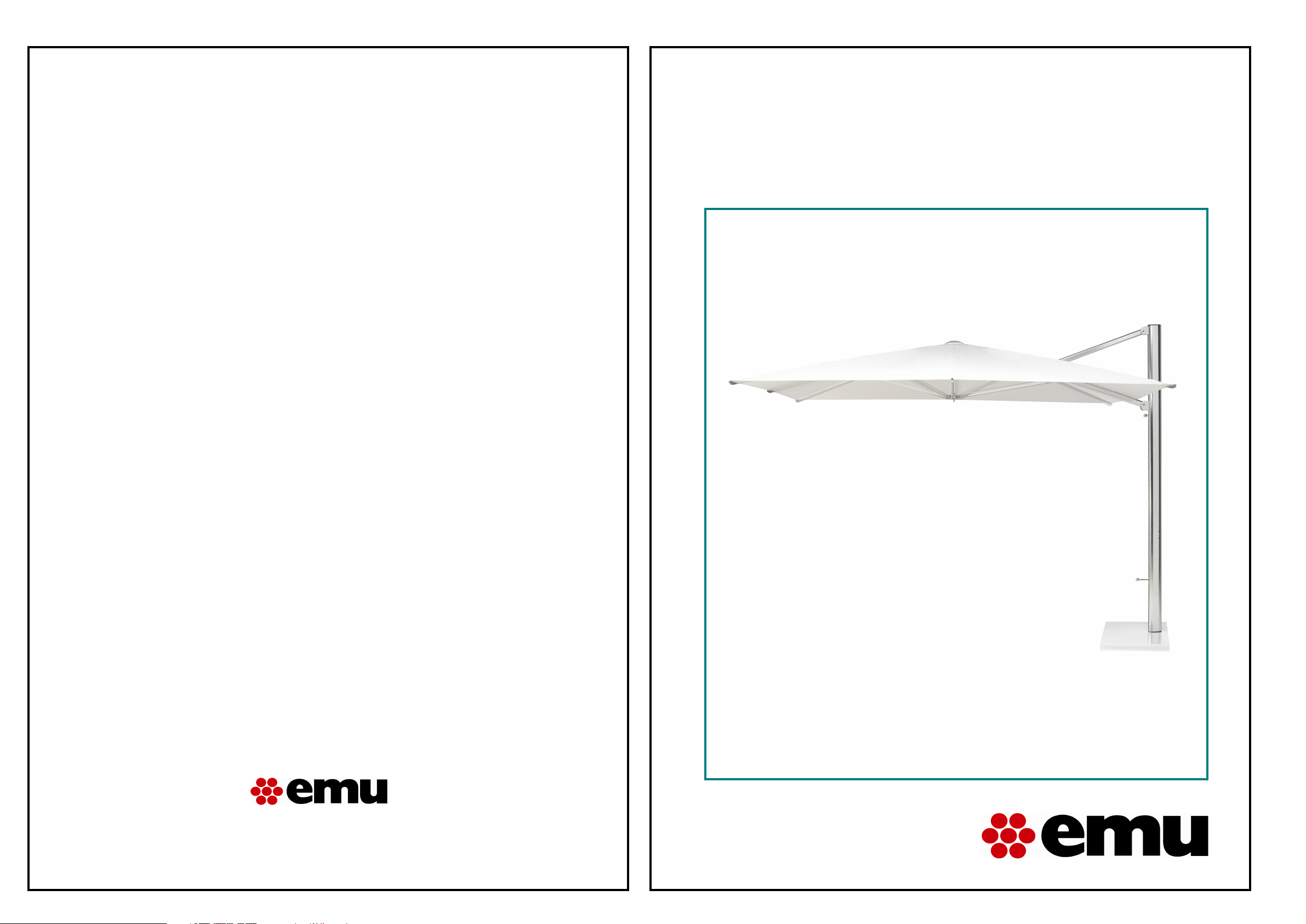
EMU SHADE UMBRELLA ART.981
IMPORTANT: Please read this entire manual before installing or operating your EMU Shade Umbrella.
Upon receipt of your SHADE art.981, please check to ensure you have received all the components. If anything is
missing or damaged, contact your seller.
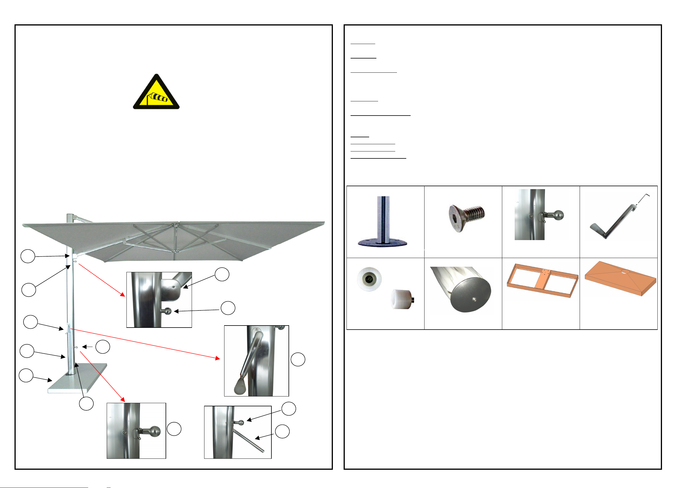
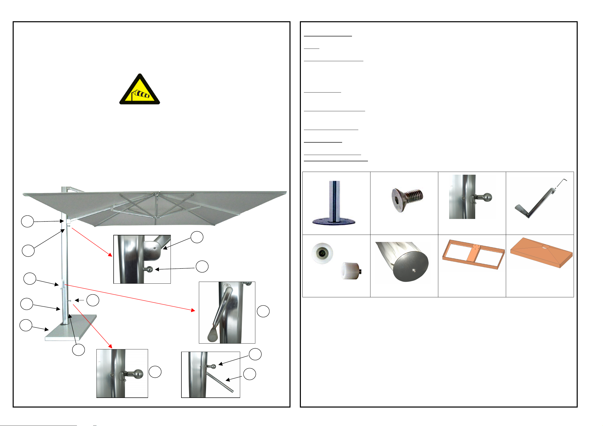
COMPONENTS, FITTINGS & HARDWARE
A. MAST:
diameter and 12 mm thick and it has 5 holes where to insert 5 bolts.
B. BOLTS
[M10X20].
C. LOCATOR PIN
TURNING HANDLE (7) is located below the LOCATOR PIN (4). When the LOCATOR PIN (4) is pulled out, the
TURNING HANDLE (7) can be lifted to rotate the MAST (2) to one of 12 holes, allowing the SHADE to rotate 360
degrees around the mast.
D. CRANK
the MAST by a screw and hexagonal key.
E. SPACER BUTTONS
: Five (5) countersunk BOLTS are used to bolt the MAST (2) to the BASE (1). BOLTS are 20mm in length.
: When the LOCATOR PIN (4) is inserted through the MAST (2), it locks the MAST (2) into place. The
: The CRANK (3) facilitates the opening and closing of the SHADE canopy structure. It must be assembled to
: Eight (8) SPACER BUTTONS are inserted into predrilled holes on the arms. SPACER
SHADE UMBRELLA WIND RESISTANCE GUIDELINES: Light to Moderate Winds
When installed properly, the Shade Umbrella is engineered to handle light to moderate wind conditions in the open
canopy position. Please adhere to these common sense wind guidelines:
1. Do not keep the Shade Umbrella in a tilt position if you are experiencing windy conditions.
2. As winds get stronger or in anticipation of uncertain/severe weather conditions, the canopy should be
lowered to the folded position and strapped to the mast.
3. The Shade Umbrella should always be left in the folded and strapped position when unattended or not in use.
4. In anticipation of and during extremely severe weather conditions, it is advisable to remove and store
the entire Shade Umbrella structure to protect it from storm-related debris.
DIAGRAM & LEGEND:
6
6
5
arms to get locked down.
F. CAP
G. BASE FRAME
H. BASE COVER
I. BALLAST (optional)
: This CAP saves the fabric cover top from injures due to the movement.
: The 1174X520 mm base frame is in e-coated steel, and it is the housing of n.4 BALLASTS.
: 1180X525 mm metal sheet cover.
: It is 500X500X50 mm ballast of weight 25 kg.
A. MAST
B. BOLT
C. LOCATOR PIN
D. CRANK
3
2
1
1. Base
2. Mast
3. Crank
4. Locator pin
5. Slider car stop pin
6. Slider car
7. Turning handle
5
E. SPACER BUTTONS F. CAP
4
3
7
4
4
7
G. BASE FRAME
1
H. BASE COVER
2
Page 3
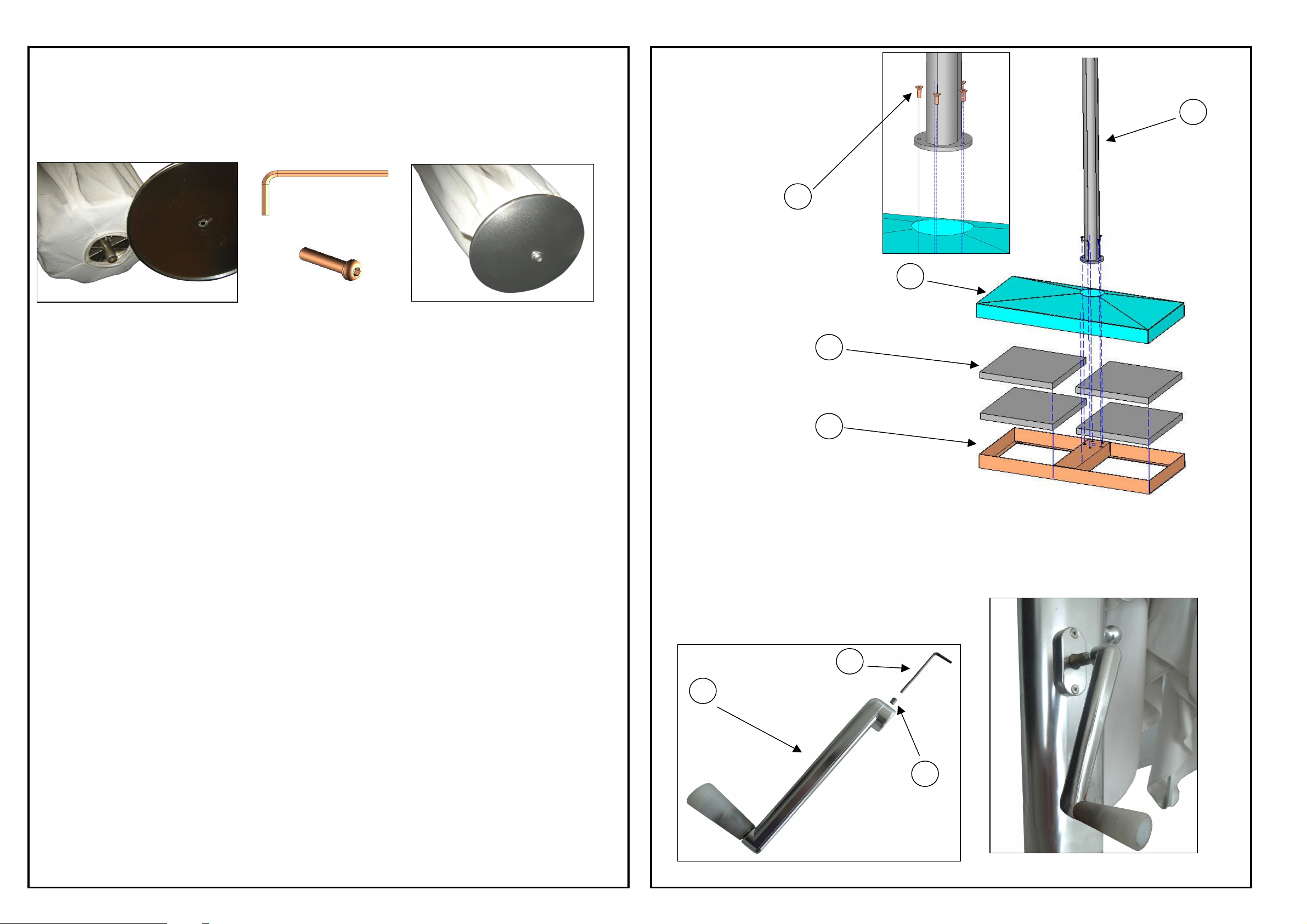
CAP ASSEMBLING
Before installing the SHADE art.981 and the basement, it needs to assemble the CAP by screw and hexagonal key. To
SHADE is provided with the not-assembled aluminium CAP, which need to protect the top fabric cover from any injure.
assemble the cap we suggest to put the umbrella over the carton board of the packaging to avoid any injures to the
fabric cover.
n.1 ROUNDED HEAD SCREW
1 2 3
1. Base frame
2. Ballast
3. Base cover
4. Mast
5. Bolts
4
5
3
2
INSTALLATION OPTIONS & GUIDELINES
To ensure longevity, correct installation is essential. There are two standard installation options which provide the best
stability for the SHADE art.981.
1. BASE
2. BASE IN-GROUND FITTING
INSTALLATION INSTRUCTIONS
To ensure proper installation, please carefully follow these instructions before installing your BASE or BASE INGROUND FITTING:
PROPER ALIGNMENT OF THE SHADE
If the exact position of the SHADE art.981 canopy (when in the open position) is important to you, it is imperative that
the installation fitting (BASE) is properly aligned. Please read the instructions below to ensure that your canopy hangs
in the desired position.
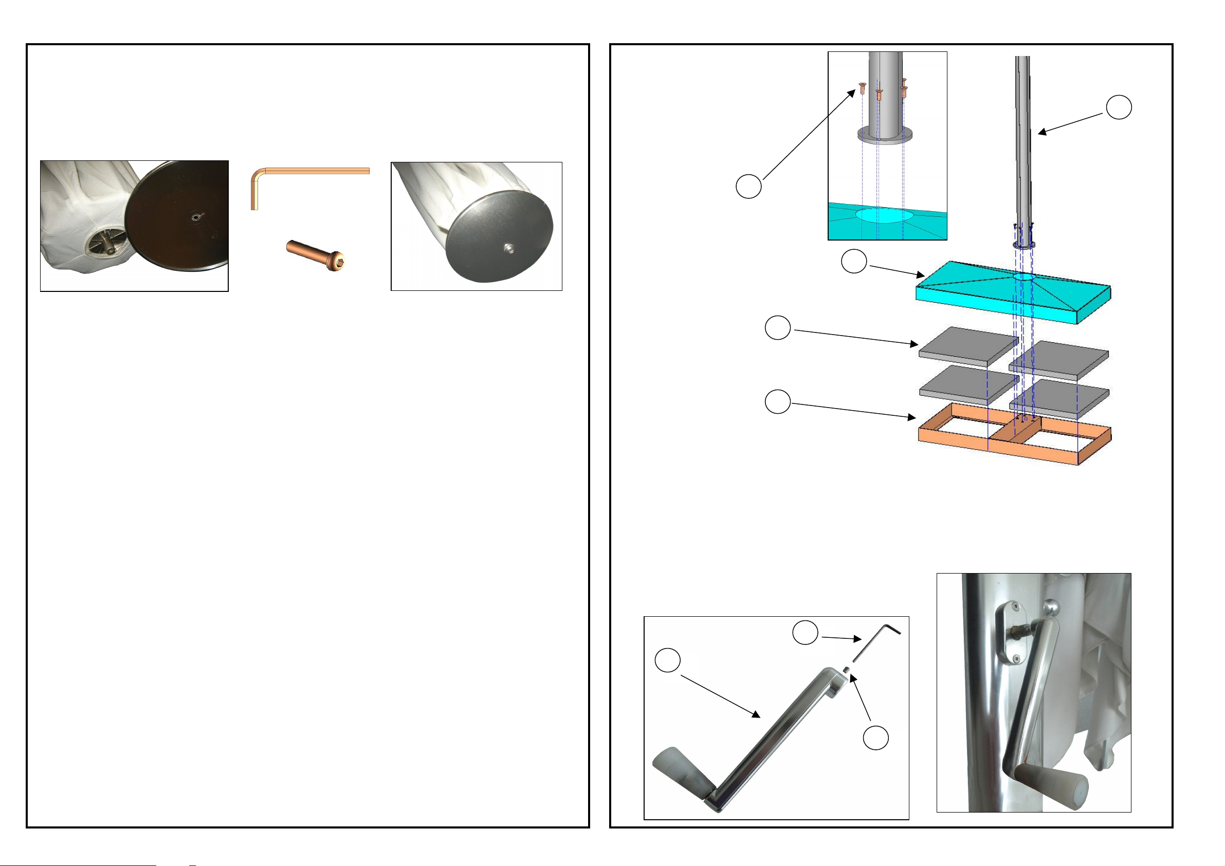
BASE INSTALLATION
Please, keep the umbrella closed and tied up with the strap to avoid that it can be opened during the assembling
process.
The BASE has five (5) threaded holes. We suggest to put n.4 BALLASTS (optional) into the BASE frame in order to
keep fixed at the ground the umbrella. The five (5) holes of the MAST(2) must be aligned to the five (5) threaded holes
of the base. The MAST must be lined up square to whatever you are aligning your SHADE with (i.e. the side of your
house, the edge of your patio, etc.), so that you can achieve the SHADE in the PRIMARY CANOPY POSITION. When
MAST holes are aligned to the BASE ones, you can start screwing the bolts to fix the MAST to the BASE.
1
CRANK ASSEMBLING
Once that you have installed the BASE with the umbrella, you can assemble the CRANK, before opening SHADE
art.981.
To assemble the CRANK you need a screw (without head) and hexagonal key you can find in the assembly kit.
You have to put the CRANK into the BRASS INSERT and fix it tightening the screw by the hexagonal key.
1. Crank
2. Screw without head
3. Hexagonal key
3
1
BASE IN-GROUND FITTING INSTALLATION
Please, keep the umbrella closed and tied up with the strap to avoid that it can be opened during the assembling
process. Pay attention to install the BASEMENT in an area without obstacles which can impede the operating of the
umbrella.
The BASE has four (4) holes to fix itself in-ground. You need steel bolts (not included) to fix it in the ground. They are
not available in SHADE assembly kit. We suggest putting n.4 BALLASTS into the housing of the base and then the
BASE COVER, aligned with the central hole. The MAST must be lined up square to whatever you are aligning your
SHADE with (i.e. the side of your house, the edge of your patio, etc.), so that you can achieve the SHADE in the
PRIMARY CANOPY POSITION. When MAST holes are aligned to the BASE ones, you can start screwing the bolts to
fix the MAST to the BASE.
The BASE can be fixed to the floors, by the holes of the BASE and suitable bolts for cement floors. Please, ask to an
hardware store the bolts most suitable for your floor.
2
3
4
Page 4
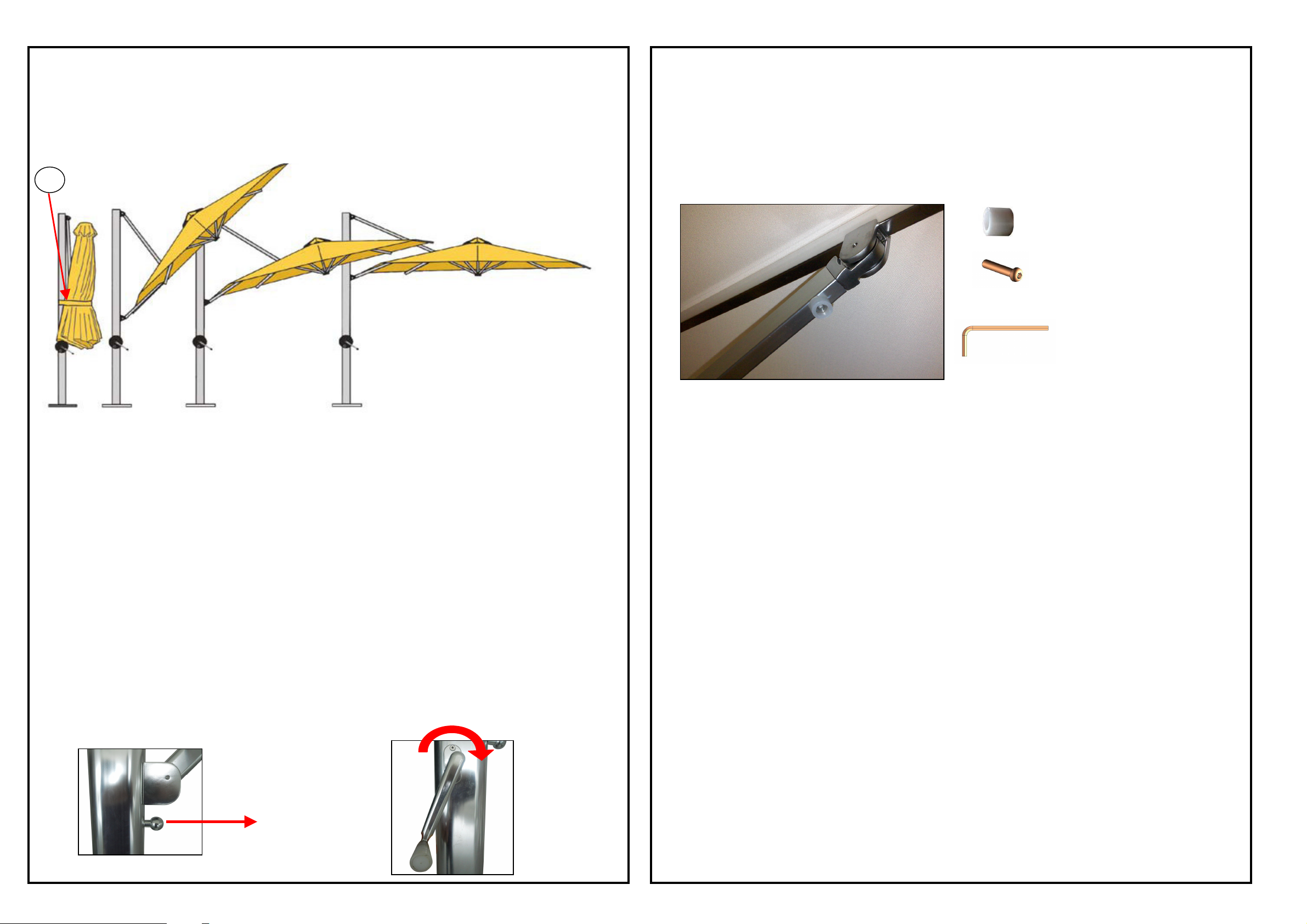
OPERATING INSTRUCTIONS
winding open the canopy. The SHADE art.981 warranty does not cover repairs resulting from not having all seven
At any time, you may skip a position and open to the desired position by keeping pulled-out the SLIDER CAR STOP PIN .
position(s) and go directly to the horizontal canopy position, you may keep the pin pulled-out and continue winding, but be
By now you have installed your BASE (in ground or not) with BALLASTS, bolted your MAST to the BASE. The
LOCATOR PIN(4) should be inserted through the MAST(2).
If the MAST is properly seated and the LOCATOR PIN properly inserted, the SHADE art.981 will not rotate or lift. You
are now ready to operate your SHADE art.981.
Your SHADE art.981 has 3 positions: Tilt Position 1, Tilt Position 2, Horizontal Position 3.
A
CAUTION:
NEVER FORCE THE ARMS OPEN IF YOU FEEL RESISTANCE IN THE WINDER! If you feel resistance in the crank,
you should manually pull out a few arms to help facilitate winding. Once the canopy is open, look up into the arms to
confirm all seven (7) SPACER BUTTONS are inserted. Please, replace the seven (7) SPACER BUTTONS already
assembled to the arms with the seven (7) SPACER BUTTONS you can find in the assembly kit. Until you have not
installed all seven (7) SPACER BUTTONS, continue to manually pull out a few arms with each opening to facilitate
SPACER BUTTONS of the assembly kit inserted.
n.7 SPACER BUTTONS
n. 7 ROUNDED HEAD SCREWS
n.1 HEXAGONL KEY
Closed 1 2 3
POSITIONS
0 Closed Position
1. Tilt Position 1 blocks extremely angular sun
2. Tilt Position 2 blocks moderately angular sun
3. Horizontal Position
NOTE: Do not use the tilt positions in windy conditions.
TO OPEN THE SHADE CANOPY
The following instructions will walk you through the sequential progression of opening the SHADE art.981 canopy
structure as shown in the diagram. At any time, you may skip a position and open to the desired position.
OPEN TO THE FIRST POSITION
1. Remove the STRAP (A) that holds the SHADE art.981 to the MAST(2) when in the closed position. Take note of
the“parachute” folding method used to fold the canopy when closed.
2. Make sure your SLIDER CAR STOP PIN(5) is pulled out.
3. Turn clockwise the CRANK(3) until the SLIDER CAR STOP PIN(5) autolocates into the lowest predetermined hole.
Continue winding until the canopy is taut. The canopy will now be in TILT POSITION 1.
4. The CRANK(3) locks automatically when you stop winding.
STEP 2.
STEP 3.
OPEN TO THE SECOND POSITION
1. Turn CRANK(3) counter-clockwise slightly to release the pressure.
2. Quickly pull out the SLIDER CAR STOP PIN(5) (making sure it stays in the horizontal position), and let it slide up the
SLIDER CAR(6) on its own until the pin autolocates in the next predetermined hole. It will be necessary to turn the
CRANK(3) a few times until the pin autolocates. Once the pin is located in the hole, continue winding until the canopy is
taut. The canopy will now be in TILT POSITION 2.
OPEN TO THE THIRD POSITION
1. Repeat steps 1-2 outlined above.
2. The canopy will now be in HORIZONTAL POSITION.
HELPFUL HINT:
In this position, the pin will NOT autolocate as it passes over the predetermined holes. If you choose to pass the tilt
sure to turn the pin back to the horizontal position before the HORIZONTAL CANOPY POSITION is attained. If you pass
the top hole, unwind the winder slightly and then pull the SLIDER CAR STOP PIN down and into the top hole.
CLOSING OF THE UMBRELLA
In every time you can close the SHADE umbrella or come back to the previous position of the umbrella, turning counterclockwise the CRANCK, and pushing the SLIDER downward, to make easier the going down of the cantilever of the
umbrella. During the closing process it needs to keep the SLIDER CAR STOP PIN pulled out from the MAST.
5 6
Page 5
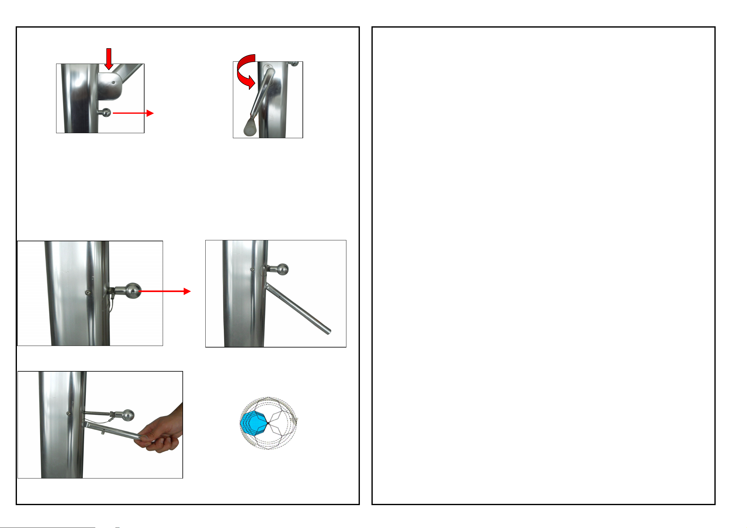
TO ROTATE THE SHADE LATERALLY THROUGH 360 DEGREES/12 POSITIONS
water (i.e. garden hose) every so often so dirt does not become ingrained. Allow the fabric to dry
where the canopy is likely to become soiled.
with a similar product, according to the current regulations.
which have been modified, altered or cleaned up with improper procedures and products.
Don't place the base on moveable or lifted bases, bases with wheels, sloped floor, and whatever unstable ground. If
There are 12 position in th MAST, you can choose the position you like following this procedure:
1. Pull out the LOCATOR PIN (4) above the TURNING HANDLE (7).
2. Raise the TURNING HANDLE (7) and rotate MAST (2) to a new position.
3. Push LOCATOR PIN (4) back in and turn it to lock it into any one of 12 positions.
MAINTAINING THE SHADE FRAME & FITTINGS
1. Hose mast and frame with water periodically, more often if installation is in a salty or industrial environ
ment.
2. Inspect the installation fitting on a regular basis and tighten if necessary.
3. Lubricate the track and slider car mechanism as needed to enhance the ease of operation. Silicon spray
or WD40 is recommended. (Spray 3-4 times per year)
MAINTAINING THE SHADE CANOPY FABRIC
1. Clean up spills and stains right away. Spills can be removed by using a clean, absorbent cloth.
2. For general maintenance, use a soft brush to remove dust and dry soil or wash down with clean, warm
naturally before closing the canopy.
3. If a thorough cleaning is necessary, sponge over the fabric using a mild soap solution (2% solution).
Rinse well with plenty of water to remove all soap residues.
4. Never use detergents, cleaning fluids or solvents. Grease and oil stains may be removed by using
turpentine or similar with an absorbent cloth.
5. We recommend giving the canopy a good cleaning on a more frequent basis if installed in a location
WARRANTY
SHADE art.981 is guaranteed by the manufacturer (Emu Group S.p.A.) against faulty workmanship, mechanical
failure and defective materials of the items and complements found at the product purchaising. SHADE art.981
canopy fabric is guaranteed against heavy discoloration or fading.
Warranty is valid 2 years since the product purchaising day.
If you find defects during the warranty time period, Emu Group S.p.A. will check the product and evaluate if it can
be covered by the warranty. Afterwards, Emu Group S.p.A. will recover the product if it is defective, or replace it
Warranty is valid since the product purchaising day and it needs to exhibit original receipt of the product.
Warranty is not valid for products that have not been well assembled, maintained, and used in a suitable way, and
Warranty doesn't cover usual strain, scratches or other damages due to accidents, careless use, lack of
maintenance, and improper use of the product.
Warranty doesn't cover accidental damages due to uncertain/severe weather conditions.
WARNINGS
Check peiodically (not less that one time per week) all the components and the junctions of the umbrella.
you need to place the umbrella on a sloped ground/floor, it needs to anchor the product to the ground/floor.
Place SHADE art.981 in safe areas, without any kind of risks and obstacles.
Please, don't give up careless opened SHADE art.981, also if weather is not windy.
1
2
If the ballasts are damaged, please, replace them, and don't use umbrellas with them.
Don't allow to children and unqualified people use components of the umbrella, in order to not make them
dangerous because of an improper use.
Emu Group S.p.A. is not responsable for the damages to things, people and the same SHADE, due to an improper
use, a mistaken installation.
SHADE UMBRELLA WIND RESISTANCE GUIDELINES: Light to Moderate Winds
When installed properly, the Shade Umbrella is engineered to handle light to moderate wind conditions in the open
canopy position. Please adhere to these common sense wind guidelines:
1. Do not keep the Shade Umbrella in a tilt position if you are experiencing windy conditions.
2. As winds get stronger or in anticipation of uncertain/severe weather conditions, the canopy should be
lowered to the folded position and strapped to the mast.
3. The Shade Umbrella should always be left in the folded and strapped position when unattended or not in use.
4. In anticipation of and during extremely severe weather conditions, it is advisable to remove and store
the entire Shade Umbrella structure to protect it from storm-related debris.
3
7
8
Page 6
OMBRELLONE EMU SHADE
IMPORTANTE: Leggere interamente questo manuale prima di installare e di aprire il tuo ombrellone SHADE
Una volta ricevuto il tuo ombrellone SHADE art. 981, assicurarsi che si siano ricevuti tutti i componenti. Se qualcosa
art.981.
manca o è danneggiato contattare il rivenditore.
LINEE GUIDA SULLA RESISTENZA AL VENTO DELL'OMBRELLONE SHADE: Venti da leggeri a moderati.
Una volta installato correttamente l'ombrellone SHADE art.981, lo stesso è adatto per essere utilizzato in condizioni
di vento leggero a moderato nella posizione con il telo aperto. Per cortesia segui queste linee guida:
1. Non tenere l'ombrellone SHADE art.981 in posizione inclinata in presenza di condizioni atmosferiche ventose.
2. Quando il vento diventa più forte o prima di condizioni atmosferiche incerte e preoccupanti, l'ombrello deve
essere chiuso, abbassato e legato al palo laterale.
3. L'ombrello va tenuto in posizione chiusa e legato al palo centrale in condizioni di non utilizzo.
4. Prima o durante condizioni meteorologiche estremamente gravi, è consigliabile rimuovere e proteggere al chiuso
l'intero ombrellone SHADE art.981 comprensivo di struttura.
COMPONENTI E VITERIE:
A. PALO LATERALE:
piastra del PALO LATERALE di diam. 145 mm e altezza 12 mm ha 5 fori su cui inserire cinque viti.
B. VITI
(1).
C. PERNO DI POSIZIONE
blocca il PALO LATERALE (2) in quella posizione. La MANIGLIA DI ROTAZIONE (7) è colocata sotto il PERNO DI
POSIZIONE (4). Quando il PERNO DI POSIZIONE (4) è tirato fuori dal PALO LATERALE (2), la MANIGLIA DI
ROTAZIONE (7) può essere sollevata per ruotare il PALO LATERALE (2) intorno all'asse per ottenere una delle 12
posizioni consentite, permettendo all'ombrellone di ruotare di 360° intorno al PALO LATERALE (2).
D. MANOVELLA
MANOVELLA (3) si trova all'interno del kit di assemblaggio e deve essere assemblata con una vite e una chiave
esagonae.
E. DISTANZIERE STECCA
presenti sulle stecche dell'ombrellone. Questi particolari devono essere lasciati inseriti poichè assicurano l'apertura
automatica dell'ombrello dello SHADE facilmente, evitando che la struttura dell'ombrello si blocchi. .
F. COVER OMBRELLO:
movimentazione dell'articolo.
G. BASAMENTO
costituisce l'alloggiamento per 4 mattonelle di zavorra..
H. COVER BASAMENTO
I. MATTONELLA (opzionale)
produttore.
: Cinque (5) VITI a testa svasata sono usati per fissare il PALO LATERALE (2) dell'ombrellone al BASAMENTO
Il PALO LATERALE (2) dello SHADE deve essere assemblato al basamento con n.5 viti. La
: Quando il PERNO DI POSIZIONE (4) è inserito all'interno del PALO LATERALE (2), esso
: La MANOVELLA (3) facilita le operazioni di apertura e chiusura dell'ombrello dello SHADE. La
: I DISTANZIERI DELLE STECCHE sono otto (8) e devono essere assemblati sui fori
Questo cover protegge la sommità del tessuto dell'ombrello da eventuali danni dovuti alla
: Il BASAMENTO ha una dimensione di 1174x520 mm ed è in acciaio trattato per un uso esterno, e
: E' di dimensioni 1180X525 mm, ed è realizzato in lamiera di acciaio piegata.
: La mattonella è di dimensioni 500X500X50 mm e del peso di 25 kg ed è consigliata dal
DIAGRAMMA & LEGENDA:
6
5
3
2
A. PALO LATERALE
B. VITE
6
5
E. DISTANZIERE STECCA F. COVER
4
3
C. PIN DI POSIZIONE
G. BASAMENTO
D. MANOVELLA
H. COVER BASAMENTO
1
7
1. Basamento
2. Palo laterale
3. Manovella
4. Perno di posizione
5. Perno bloccaggio slider
6. Slider
7. Maniglia per rotazione
4
4
7
9
10
Page 7
Fare attenzione a verificare che l'ombrellone venga installato in una zona libera da ostacoli che possano impedire il suo
ASSEMBLAGGIO COVER
Prima di installare lo SHADE art.981 e il BASAMENTO è necessario assemblare il COVER OMBRELLO con una vite a
L'ombrellone SHADE art.981 è provvisto di un COVER da assemblare alla struttura per proteggere la sommità del
tessuto dell'ombrello da eventuali danneggiamenti per movimentazione.
testa bombata e una chiave esagonale (presenti nel kit di assemblaggio).
Per eseguire questa operazione si consiglia di appoggiare l'ombrello sopra il cartone degli imballi per evitare
danneggiamenti.
n.1 VITE TESTA BOMBATA
1 2 3
LINEE GUIDA PER INSTALLAZIONE DELL'OMBRELLONE SHADE
Per assicurare longevità all'ombrellone, una corretta installazione dell'ombrellone è essenziale. Ci sono due opzioni di
installazione standard che forniscono una buona stabilità all'ombrellone SHADE:
1. Installazione su BASAMENTO.
2. Installazione su BASAMENTO fissato a terra.
ISTRUZIONI DI INSTALLAZIONE
Per assicurae una corretta installazione, segui attentamente le seguenti istruzioni.
1. Basamento
2. Mattonella
3. Cover basamento
4. Palo laterale
4
5
3
2
1
ALLINEAMENTO CORRETTO DELL'OMBRELLONE SHADE
Se l'esatta posizone dell'ombrello dello SHADE art.981 (in configurazione aperta) è importante, è assoluatmente
necessario che l'ombrellone venga assemblato al BASAMENTO (1) con l'orientamento desiderato e con l'allineamento
dei fori del PALO LATERALE (2) e del BASAMENTO (1).
INSTALLAZIONE SU BASAMENTO
Si raccomanda di tenere l'ombrellone legato con l'apposito laccio, per evitare che si apra durante la fase di montaggio.
Il BASAMENTO (1) ha 5 fori filettati. Prima di assemblare l'ombrellone al BASAMENTO 81), è necessario collocare n.4
MATTONELLE all'interno del BASAMENTO (1) come zavorra. I cinque fori del PALO LATERALE devono essere
allineati ai cinque fori filettati del BASAMENTO (1). Il PALO LATERALE (2) deve essere posizionato in senso
ortogonale rispetto a ciò con cui si vuole allineare lo SHADE (per esempio, il lato di una casa, l'angolo di un cortile,
etc.), così che si può ottenere l'ombrellone SHADE art.981 nella POSIZIONE PRIMARIA. Quando i 5 fori dei due
componenti sono allineati, si può iniziare ad avviarte le viti su di essi.
INSTALLAZIONE SU BASAMENTO FISSATO A TERRA
Si raccomanda di tenere l'ombrellone legato con l'apposito laccio, per evitare che si apra durante la fase di montaggio.
utilizzo.
Il BASAMENTO (1) ha 4 fori per fissare lo stesso a terra. E' necessario disporre di picchetti (non inclusi nella
confezione) per il fissaggio a terra del BASAMENTO (1). Nonostante il BASAMENTO (1) sia fissato a terra, si
suggerisce di inserire n.4 MATTONELLE all'interno del BASAMENTO (1) come zavorra. I cinque fori del PALO
LATERALE (2) devono essere allineati ai cinque fori filettati del BASAMENTO (1). Il PALO LATERALE (2) deve essere
posizionato in senso ortogonale rispetto a ciò con cui si vuole allineare lo SHADE (per esempio, il lato di una casa,
l'angolo di un cortile, etc.), così che si può ottenere l'ombrellone SHADE art.981 nella POSIZIONE PRIMARIA. Quando
i 5 fori dei due componenti sono allineati, si può iniziare ad avviarte le viti su di essi.
Su pavimenti, il BASAMENTO (1) può essere fissato tramite gli appositi fori con degli stop. Scegliere in ferramenta
quelli più adeguati e idonei in funzione del tipo di pavimento.
ASSEMBLAGGIO DELLA MANOVELLA
Una volta installato il BASAMENTO (1) con il PALO LATERALE (2), è necessario assemblare la manovella, prima di
aprire l'ombrellone SHADE art.981.
Per assemblare la manovella è necessario utilizzare n.1 vite senza testa e chiave a brucola presenti nel kit di
assemblaggio. e' necessario inserire la manovella nell'inserto di ottone presente sul PALO LATERALE (2) e serrare la
vite con la chiave a brucola.
1. Manovella
2. Vite senza testa
3. Chiave a brucola
3
1
2
11
12
Page 8

ISTRUZIONI PER LE OPERAZIONI DI APERTURA E CHIUSURA OMBRELLONE
per facilitare la rotazione della manovella. La garanzia dell'ombrellone SHADE art.981 non copre danni dovuti al fatto
meccanico che tiene sollevato l'ombrello. Durnate la chiusura è necessario mantenere il PERNO BLOCCAGGIO SLIDER
4. La MANOVELLA si blocca automaticamente nel momento in cui si finisce di ruotarla.
A questo punto, è stato installato l'ombrellone sul BASAMENTO comprensivo di MATTONELLE. Il PERNO DI
POSIZIONE dovrebbe essere inserito dentro al PALO LATERALE (2).
Se il PALO LATERALE è correttamente installato sul BASAMENTO e il PERNO DI POSIZIONE opportunamente
inserito nel PALO LATERALE, l'ombrellone SHADE art.981 non ruota e non si solleva. In queste condizioni è possibile
avvciare la procedura di apertura dell'ombrellone.
L'ombrellone SHADE art.981 ha 3 posizioni: Posizione inclinata 1, Posizione inclinata 2, Posizione orizzontale 3.
A
ATTENZIONE:
NON FORZARE MAI LE STECCHE DELL'OMBRELLONE NEL CASO IN CUI SI AVVERTE REISTENZA NELLA
MANOVELLA! Se si avverte resistenza nella manovella, è necessario tirare manualmente e delicatamente alcune
stecche dell'ombrellone per facilitare la rotazione della manovella. Una volta che l'ombrello si è aperto, verificare che
all'interno dell'ombrello, in corrispondenza delle stecche, siano presenti 7 DISTANZIERI STECCA, assemblati
mediante viti alle stecche stesse. Sostituire i 7 DISTANZIERI STECCHE, già assemblati all'ombrellone, con i 7
DISTANZIERI STECCHE presenti nel kit di assemblaggio. Finchè non si è proceduto ad assemblare i DISTANZIERI
STECCHE del kit di assemblaggio, è necessario continuare ad tirare manualmente alcune stecche dell'ombrellone
di non aver assemblato i DISTANZIERI STECCHE del kit di assemblaggio dell'ombrellone.
n.7 DISTANZIERI STECCHE
n. 7 VITI TESTA
n.1 CHIAVE A BRUCOLA
Chiuso 1 2 3
POSIZIONI
0 Configurazione chiusa
1. Posizione inclinata 1 - protegge dai raggi solari estremamente inclinati.
2. Posizione inclinata 2 - protegge dai raggi solari moderatamente inclinati.
3. Poszione orizzontale.
NOTA: Non usare l'ombrellone in posizione inclinata in condizioni meteorologiche ventose.
APERTURA DELL'OMBRELLO DELLO SHADE
Le seguenti istruzioni indicano la procedura sequenziale da seguire per aprire l'ombrellone SHADE art.981, come
mostrato nel diagramma superiore. In qualsiasi momento è possibile saltare una posizone ed aprire l'ombrellone nella
posizione desiderata.
APERTURA DELL'OMBRELLO NELLA PRIMA POSIZONE
1. Rimuovere il laccio (A) che tiene l'ombrello dello SHADE art.981 accanto al PALO LATERALE in posizone chiusa.
2. Controllare che il PERNO BLOCCAGGIO SLIDER sia al tirato fuori dal PALO LATERALE.
3. Ruotare in senso orario la MANOVELLA finchè il PERNO BLOCCAGGIO SLIDER si inserisce automaticamente nel
predeterminato foro più basso. Continuare a girare la manovella finchè il telo dell'ombrello risulti rigido. Adesso
l'ombrellone è in POSIZIONE INCLINATA 1.
FASE 3.
FASE 2.
APERTURA DELL'OMBRELLO NELLA SECONDA POSIZONE
1. Ruotare leggermente la MANOVELLA in senso anti-orario per rilasciare la pressione sul perno.
2. Tirare velocemente il PERNO BLOCCAGGIO SLIDER, e far scorrere lo SLIDER autonomamente, finchè il PERNO si
inserisce automaticamente nel prossimo predeterminato foro.E' necessario ruotare la MANOVELLA per un pò affinchè il
PERNO BLOCCAGGIO SLIDER si inserisca autonomamente nel foro. Una volta che il perno si è posizionato, continuare
a ruotare la MANOVELLA finchè il telo dell'ombrellone diventi teso.
L'ombrellone adesso si trova in POSIZONE INCLINATA 2.
APERTURA DELL'OMBRELLO NELLA TERZA POSIZONE
1. Ripetere i passaggi sopra da 1 a 2.
2. L'ombrellone si trova in POSIZIONE ORIZZONTALE.
SUGGERIMENTO:
In qualsiasi momento è possibile saltare una posizione e aprire l'ombrellone nella posizione desiderata mantenendo il
PERNO BLOCCAGGIO SLIDER esternamente al PALO LATERALE. In questa posizione, il perno NON si inserisce
automaticamente nel foro, perchè oltrepassa i predeterminati fori. Se si sceglie di oltrepassare le posizioni inclinati 1 e 2,
e andare direttamente alla posizione orizzontale, è necessario manetnere il PERNO BLOCCAGGIO SLIDER esterno al
PALO LATERALE e continuare a ruotare la MANOVELLA. Attenzione, prima di raggiungere la POSIZIONE
ORIZZONTALE è necessario inserire il PERNO BLOCCAGGIO SLIDER all'interno del PALO LATERALE.
Nel caso in cui l'ultimo predeterminato foro venga oltrepassato, ruotare in senso anti orario la manovella leggermente
finchè il PERNO BLOCCAGGIO SLIDER si inserisca autonomamente nel foro superiore.
13
CHIUSURA OMBRELLONE
In qualsiasi momento è possibile chiudere l'ombrellone o tornare alla poszione precedente, ruotando la MANOVELLA in
senso anti-orario e facendo pressione verso il basso sullo SLIDER (6) così da spingere verso il basso il braccio
al di fuori del PALO LATERALE.
14
Page 9

RUOTARE L'OMBRELLONE SHADE DI 360°/12 POSIZIONI
Verificare periodicamente (almeno ogni settimana) tutte le parti in movimento e le varie giunzioni dello SHADE art.981.
E' possibile ruotare l'ombrellone intorno al PALO LATERALE di 360°/12 posizioni.
1. Tirare fuori il PERNO DI POSIZIONE (4), appena sopra la MANIGLIA PER ROTAZIONE (7).
2. Sollevare la MANIGLIA PER ROTAZIONE (7) e ruotare il PALO LATERALE (2) nella posizione desiderata.
3. Spingere il PERNO DI POSIZIONE (4) all'interno del PALO LATERALE (2) in una delle 12 posizioni consentite.
MANUTENZIONE DELLA STRUTTURA DELL'OMBRELLONE E VITERIE
1. Pulire con un getto d'acqua il palo laterale e la struttura di alluminio periodicamente, e più spesso se l'ombrellone è
stato installato in un ambiente marino o industriale.
2. Verificare l'assemblaggio delle viterie sulla base e serrare periodicamente se necessario.
3. Lubrificare la guida e lo slider, per rendere più semplice lo scorrimento sul palo laterale. Sono consigliati spray
lubrificanti al teflon, 3-4 volte per anno.
MANUTENZIONE DEL TESSUTO DELL'OMBRELLONE
1. Pulire macchie presenti sul telo, utilizzando un panno pulito ed assorbente.
2. Per una manutenzione generale, usare una spazzola morbida per rimuovere la polvere o terra secca, o sciacquare
spesso con acqua calda e pulita spesso per non far radicare la sporcizia nel tessuto. Permettere al tessuto di
asciugarsi naturalmente prima di chiudere l'ombrellone.
3. Se è necessaria una pulizia radicale, pulire con una spugna usando una delicata soluzione di sapone neutro (2% in
soluzione). Risciacquare abbondantemente e interamente il telo per rimuovere residui di sapone.
4. Non usare mai detergenti e solventi. Macchie di grasso e olio possono essere rimosse usando opportuni
smacchiatori idonei per tessuto poliestere con un panno assorbente.
5. Si raccomanda di pulire il telo dell'ombrellone molto frequentemente, se installato in un posto in cui è soggetto a
diventare sporco facilmente.
GARANZIA
La garanzia copre eventuali difetti riscontrati nei materiali e nella realizzazione dei componenti dello SHADE art.981 e
complementi dalla data di acquisto. La garanzia copre eventuali notevoli scolorimenti del tessuto dell'ombrellone.
La garanzia è valida 2 anni a partire dalla data di acquisto del prodotto.
Nel caso in cui si riscontrassero difetti nel periodo di garanzia, Emu Group S.p.A. esaminerà il prodotto e valuterà se il
problema rientra nella copertura della garanzia. A seguito dell'esame del prodotto, Emu Group S.p.A. riparerà lo stesso
se difettoso o provvederà a sostituirlo con un prodotto uguale o paragonabile, a suo giudizio, nel rispetto della
normativa vigente.
La garanzia è valida a partire dalla data di acquisto del prodotto ed è necessario esibire lo scontrino in originale del
prodotto.
La garanzia non èo applicata al prodotto che è stato conservato o montato in modo non corretto, usato in modo non
adeguato, che è stato manomesso, alterato o pulito con procedure o prodotti non idonei. La garanzia non copre il
normale logorio, tagli, graffi oppure danni provocati da urti, incidenti, mancanza di manutenzione e uso improprio del
prodotto. La garanzia non copre danni accidentali dovuti a condizioni meteorologiche gravose per il prodotto.
AVVERTENZE D'USO
Non posizionare il basamento dello SHADE art.981 su: piedistalli mobili o rialzati, carrelli con ruote, piani inclinati, e
qualsiasi tipo di terreno instabile. Dove si renda indispensabile posizionare l'ombrellone su un piano inclinato è
necessario ancorare il prodotto al pavimento.
E' necessario posizionare lo SHADE art.981 all'interno di zone sicure e prive di qualsiasi tipologia di rischio.
1
3
2
Non lasciare mai lo SHADE art.981 aperto incostudito, anche in assenza di vento.
Se la zavorra presenta segni di deterioramento provvedere a sostituire le parti deteriorate, non utilizzare lo SHADE
art.981 con parti di zavorra mancanti o fratturate.
Non permettere a bambini o persone non componenti di utilizzare i componenti dell'ombrellone, affinchè gli stessi non
diventino pericolosi per un uso improprio.
La Emu Group S.p.A. non si assume nessuna repsonsabilità qualora, a causa di un uso improprio, di errata
installazione, della non osservanza di queste condizioni, si provochino danni a cose, persone o allo stesso ombrellone.
LINEE GUIDA SULLA RESISTENZA AL VENTO DELL'OMBRELLONE SHADE: Venti da leggeri a moderati.
Una volta installato correttamente l'ombrellone SHADE art.981, lo stesso è adatto per essere utilizzato in condizioni di
vento leggero a moderato nella posizione con il telo aperto. Per cortesia segui queste linee guida:
1. Non tenere l'ombrellone SHADE art.981 in posizione inclinata in presenza di condizioni atmosferiche ventose.
2. Quando il vento diventa più forte o prima di condizioni atmosferiche incerte e preoccupanti, l'ombrello deve essere
chiuso, abbassato e legato al palo laterale.
3. L'ombrello va tenuto in posizione chiusa e legato al palo centrale in condizioni di non utilizzo.
4. Prima o durante condizioni meteorologiche estremamente gravi, è consigliabile rimuovere e proteggere al chiuso
l'intero ombrellone SHADE art.981 comprensivo di struttura..
15
16
Page 10

PARASOL EMU SHADE
jusqu'à modéré dans la position ouverte. Veuillez suivre ces lignes directrices :
2. Lorsque le vent devient plus fort ou avant des conditions atmosphériques incertaines et préoccupantes, le parasol doit
LE MÂT LATÉRAL (2) du SHADE doit être assemblé à la BASE à l'aide de 5 vis. La plaque du MÂT
Lorsque la GOUPILLE DE POSITION (4) est tirée hors du MÂT LATÉRAL (2), la POIGNÉE DE ROTATION (7) peut être
A. MÂT LATÉRAL
IMPORTANT : Lire tout le contenu de ce manuel avant d'installer et d'ouvrir votre parasol SHADE art.981.
Au moment de la livraison du parasol SHADE art. 981, veuillez vous assurer d'avoir aussi reçu tous les composants. S'il
manque quelque chose ou si un composant est endommagé, contacter le revendeur.
LIGNES DIRECTRICES SUR LA RÉSISTANCE DU PARASOL SHADE AU VENT : Vents légers jusqu'à modérés.
Après avoir correctement installé le parasol SHADE art.981, celui-ci s'adapte parfaitement aux conditions de vent léger
1. Ne pas garder le parasol SHADE art.981 dans la position inclinée dans des conditions de vent.
être fermé, abaissé et lié au mât latéral.
3. Lorsque le parasol n'est pas utilisé, il faut le garder fermé et lié au mât central.
4. Avant ou durant des conditions météorologiques extrêmement graves, il est conseillé d'enlever et de mettre tout le
parasol SHADE art.981 avec sa structure à l'abri.
DIAGRAMME & LÉGENDE :
COMPOSANTS ET VIS :
A. MÂT LATÉRAL :
LATÉRAL de 145 mm de diamètre et de 12 mm de hauteur a 5 trous où introduire 5 vis.
B. VIS
C. GOUPILLE DE POSITION
bloque ce dernier dans cette position. La POIGNÉE DE ROTATION (7) se trouve sous la GOUPILLE DE POSITION (4).
soulevée pour faire tourner le MÂT LATÉRAL (2) autour de l'axe pour obtenir l'une des 12 positions permises, en
permettant au parasol de tourner de 360° autour du MÂT LATÉRAL (2).
D. MANIVELLE
MANIVELLE (3) se trouve dans le kit d'assemblage et doit être assemblée avec une vis et une clé hexagonale.
E. ÉCARTEUR BALEINE
trouvant sur les baleines du parasol. Il faut les laisser introduits car ils garantissent l'ouverture automatique et aisée du
parasol SHADE, en évitant que la structure du parasol ne se bloque.
F. COUVERTURE DE PROTECTION DU PARASOL (COVER) :
dommages dus au transport de l'article.
G. BASE
pour les 4 briques.
H. COVER BASE
I. BRIQUE (en option)
: Cinq (5) VIS à tête fraisée sont employées pour fixer le MÂT LATÉRAL (2) du parasol à la BASE (1).
: Lorsque la GOUPILLE DE POSITION (4) est introduite dans le MÂT LATÉRAL (2), elle
: La MANIVELLE (3) facilite les opérations d'ouverture et de fermeture du parasol SHADE. La
: LES ÉCARTEURS DES BALEINES sont huit (8) et doivent être assemblés sur les trous se
Elle protège le sommet du tissu du parasol contre tous
: La BASE a 1174x520mm de dimension et est en acier traité pour usage externe, elle constitue le logement
: elle a 1180X525mm de dimension et est en tôle d'acier pliée.
: La brique a 500X500X50mm de dimension et pèse 25 kg, elle est conseillée par le fabricant.
6
5
3
2
1
1. Base
2. Mât latéral
3. Manivelle
4. Goupille de position
5. Goupille de blocage
bague coulissante
6. Bague coulissante
7. Poignée pour rotation
B. VIS
6
5
E. ÉCARTEUR BALEINE F. COVER
4
3
7
4
4
7
C. PIN DE POSITION
G. BASE
17
D. MANIVELLE
H. COVER BASE
18
Page 11

Veuillez garder le parasol lié avec le lacet prévu pour éviter qu'il ne s'ouvre durant le montage.
ASSEMBLAGE COUVERTURE DE PROTECTION (COVER)
Le parasol SHADE art.981 est pourvu d'une couverture de protection (cover) à assembler à la structure pour protéger
le sommet du tissu contre les dommages éventuels dus à la manipulation et transport.
Avant d'installer le SHADE art.981 et la BASE, il faut assembler la COUVERTURE DE PROTECTION (COVER) du
PARASOL à l'aide d'une vis à tête bombée et d'une clé hexagonale se trouvant dans le kit d'assemblage).
Pour effectuer cette opération, veuillez appuyer le parasol sur le carton de l'emballage pour éviter de l'endommager.
n.1 VIS À TÊTE BOMBÉE
1 2 3
1. Base
2. Brique
3. Cover base
4. Mât latéral
4
5
3
LIGNES DIRECTRICES POUR L'INSTALLATION DU PARASOL SHADE
Pour que le parasol dure dans le temps, il est essentiel de l'installer correctement. Il y a deux options d'installation
standard pouvant donner une bonne stabilité au parasol SHADE :
1. Installation sur BASE.
2. Installation sur BASE fixée au sol.
INSTRUCTIONS POUR L'INSTALLATION
Pour une installation correcte, suivre scrupuleusement les instructions suivantes.
ALIGNEMENT CORRECT DU PARASOL SHADE
Si la position exacte du parasol SHADE art.981 (en configuration ouverte) est importante, il est absolument nécessaire
que le parasol soit assemblé à la BASE (1) avec l'orientation désirée et avec l'alignement des trous du MÂT LATÉRAL
(2) et de la BASE 1).
INSTALLATION SUR LA BASE
La BASE (1) a 5 trous filetés. Avant d'assembler la parasol à la BASE 81), il faut placer 4 BRIQUES dans la BASE (1)
comme lest. Les cinq trous du MÂT LATÉRAL doivent être alignés aux cinq trous filetés de la BASE (1). Le MÂT
LATÉRAL (2) doit être positionné dans le sens orthogonal par raport avec ce que l'on désire aligner, le parasol SHADE
(par exemple, le côté d'une maison, le coin d'une cour, etc.), afin d'obtenir le parasol SHADE art.981 dans la
POSITION PRIMAIRE. Lorsque les 5 trous des deux composants sont alignés, on peut commencer à visser les vis.
INSTALLATION SUR LA BASE FIXÉE AU SOL
Nous recommandons de garder le parasol lié avec le lacet prévu pour éviter qu'il ne s'ouvre pendant le montage. Faire
attention à ce que le parasol soit installé dans une zone sans obstacles pouvant empêcher de l'utiliser.
La BASE (1) a 4 trous pour être fixée au sol. Il faut disposer de piquets (non inclus dans l'emballage) pour fixer la
BASE (1) au sol. Même si la BASE (1) est fixée au sol, nous suggérons d'introduire 4 BRIQUES dans la BASE (1)
comme lest. Les cinq trous du MÂT LATÉRAL (2) doivent être alignés aux cinq trous filetés de la BASE (1). Le MÂT
LATÉRAL (2) doit être positionné dans le sens orthogonal par rapport avec ce que l'on désire aligner, le parasol
SHADE (par exemple, le côté d'une maison, le coin d'une cour, etc.), afin d'obtenir le parasol SHADE art.981 dans la
POSITION PRIMAIRE. Lorsque les 5 trous des deux composants sont alignés, on peut commencer à visser les vis.
Sur les pavés, la BASE (1) peut être fixée à travers les trous prévus avec des arrêts. Choisir dans une quincaillerie
ceux les plus appropriés en fonction du type de pavés.
2
1
ASSEMBLAGE DE LA MANIVELLE
Après avoir installé la BASE (1) avec le MÂT LATÉRAL (2), il faut assembler la manivelle avant d'ouvrir le parasol
SHADE art.981.
Pour assembler la manivelle, utiliser la vis sans tête et la clé Allen se trouvant dans le kit d'assemblage, il faut
introduire la manivelle dans l'insert en laiton se trouvant sur la MÂT LATÉRAL (2) et serrer la vis avec la clé Allen.
1. Manivelle
2. Vis sans tête
3. Clé Allen
3
1
2
19
20
Page 12

INSTRUCTIONS POUR LES OPÉRATIONS D'OUVERTURE ET DE FERMETURE DU PARASOL
PHASE 2.
PHASE 3.
GOUPILLE DE BLOCAGE DE LA BAGUE COULISSANTE à l'extérieur du MÂT LATÉRAL. Dans cette position la goupille
contraire des aiguilles d'une montre et en faisant pression vers le bas sur la BAGUE COULISSANTE (6) de manière à pousser vers le
4. La MANIVELLE se bloque automatiquement à l'instant où l'on termine de la faire tourner.
Le parasol est à ce stade installé sur la BASE avec les BRIQUES. La GOUPILLE DE POSITION devrait être introduite
dans le MÂT LATÉRAL (2).
Si le MÂT LATÉRAL est bien installé sur la BASE et que la GOUPILLE DE POSITION est introduite dans le MÂT
LATÉRAL, le parasol SHADE art.981 ne tourne et ne se soulève pas. Il est donc possible de procéder à l'ouverture de
ce dernier.
Le parasol SHADE art.981 a 3 positions : Position inclinée 1, Position inclinée 2, Position horizontale 3.
A
ATTENTION :
NE JAMAIS FORCER LES BALEINES DU PARASOL EN CAS DE RÉSISTANCE DE LA MANIVELLE ! Si l'on
remarque une résistance de la manivelle, il faut tirer délicatement à la main quelques baleines du parasol pour
faciliter la rotation de la manivelle. Lorsque le parasol est ouvert, vérifier que dans ce dernier, en correspondance
des baleines, se trouvent les 7 ÉCARTEURS BALEINE, assemblés par des vis aux baleines. Remplacer les 7
ÉCARTEURS BALEINES, déjà assemblés au parasol, par les 7 ÉCARTEURS BALEINES se trouvant dans le kit
d'assemblage. Jusqu'au moment où l'on a assemblé les ÉCARTEURS BALEINES du kit d'assemblage, il faut
continuer à tirer à la main certaines baleines pour faciliter la rotation de la manivelle. La garantie du parasol SHADE
art.981 ne couvre pas les dommages dus au fait de ne pas avoir assemblé les ÉCARTEURS BALEINES du kit
d'assemblage du parasol.
n.7 ÉCARTEURS BALEINES
n. 7 VIS TÊTE
n.1 CLÉ ALLEN
POSITIONS
0 Configuration fermée
1. Position inclinée 1 - protège des rayons de soleil extrêmement inclinés.
2. Position inclinée 2 - protège des rayons de soleil modérément inclinés.
3. Position horizontale.
NOTE : Ne pas utiliser le parasol dans une position inclinée dans des conditions de vent
OUVERTURE DU PARASOL SHADE
Le instructions suivantes indiquent les séquences de la procédure à suivre pour ouvrir le parasol SHADE art.981,
comme illustré sur la figure ci-dessus. Il est à tout moment possible de sauter une position et d'ouvrir le parasol dans la
position souhaitée.
OUVERTURE DU PARASOL DANS LA PREMIÈRE POSITION
1. Enlever le lacet (A) qui maintient le parasol SHADE art.981 à côté du MÂT LATÉRAL en position fermée.
2. Vérifier que la GOUPILLE DE BLOCAGE DE LA BAGUE COULISSANTE est tirée hors du MÂT LATÉRAL.
3. Tourner dans le sens des aiguilles d'une montre la MANIVELLE jusqu'à ce que la GOUPILLE DE BLOCAGE DE LA
BAGUECOULISSANTE s'introduise automatiquement dans le trou le plus bas. Continuer à tourner la manivelle jusqu'à
ce que la toile du parasol soit rigide. Le parasol est à présent en POSITION INCLINÉE 1.
OUVERTURE DU PARASOL DANS LA DEUXIÈME POSITION
1. Faire tourner légèrement la MANIVELLE dans le sens contraire aux aiguilles d'une montre pour relâcher la pression
sur la goupille.
2. Tirer rapidement la GOUPILLE DE BLOCAGE DE LA BAGUE COULISSANTE et faire coulisser cette dernière jusqu'à
ce que la GOUPILLE ne s'introduise automatiquement dans le trou suivant prévu. Il faut faire tourner la MANIVELLE
pendant un moment afin que la GOUPILLE DE BLOCAGE DE LA BAGUE COULISSANTE ne s'introduise dans le trou.
Lorsque la goupille est bien positionnée, continuer à faire tourner la MANIVELLE jusqu'à ce que la toile du parasol soit
bien tendue.
Le parasol se trouve à présent dans la POSITION INCLINÉE 2.
OUVERTURE DU PARASOL DANS LA TROISIÈME POSITION
1. Répéter les passages de 1 à 2 susmentionnés.
2. Le parasol se trouve dans la POSITION HORIZONTALE.
SUGGESTION :
Il est possible à tout moment de sauter une position et d'ouvrir le parasol dans la position souhaitée en gardant la
NE s'introduit PAS automatiquement dans le trou car elle dépasse les trous prévus. Si l'on choisit de sauter les positions
inclinées 1 et 2 et d'aller directement à la position horizontale, il faut garder la GOUPILLE DE BLOCAGE DE LA BAGUE
COULISSANTE à l'extérieur du MÂT LATÉRAL et continuer à faire tourner la MANIVELLE. Attention, avant d'atteindre la
POSITION HORIZONTALE, il faut introduire la GOUPILLE DE BLOCAGE DE LA BAGUE COULISSANTE dans la MÂT
LATÉRAL.
Si l'on dépasse le dernier trou prévu, faire tourner légèrement la manivelle dans le sens contraire des aiguilles d'une
montre jusqu'à ce que la GOUPILLE DE BLOCAGE DE LA BAGUE COULISSANTE s'introduise dans le trou supérieur.
21
FERMETURE DU PARASOL
Il est possible de fermer à tout moment le parasol et de revenir à la position précédente, en tournant la MANIVELLE dans le sens
bas le bras mécanique qui maintient le parasol soulevé. Il faut, pendant la fermeture, maintenir la GOUPILLE DE BLOCAGE DE LA
BAGUE COULISSANTE hors du MÂT LATÉRAL.
22
Page 13

TOURNER LE PARASOL SHADE DE 360°/12 POSITIONS
Vérifier périodiquement (au moins une fois par semaine) toutes les parties en mouvement et les différentes jonctions du
Emu Group S.p.A. décline toute responsabilité quant aux dommages causés aux objets, personnes et parasol dus à un
Lorsque le parasol SHADE art.981 est bien installé, il peut être utilisé dans des conditions de vent léger à modéré dans
4. Avant ou durant des conditions météorologiques extrêmement graves, il est conseillé de retirer et de mettre à l'abri le
Il est possible de faire tourner le parasol autour du MÂT LATÉRAL de 360°/12 positions.
1. Tirer au-dehors la GOUPILLE DE POSITION (4), juste au-dessus de la POIGNÉE POUR LA ROTATION (7).
2. Soulever la POIGNÉE POUR LA ROTATION (7) et tourner le MÂT LATÉRAL (2) dans la position souhaitée.
3. Pousser la GOUPILLE DE POSITION (4) dans la MÂT LATÉRAL (2) dans l'une des 12 positions permises.
ENTRETIEN DE LA STRUCTURE DU PARASOL ET DES VIS
1. Nettoyer périodiquement à l'aide d'un jet d'eau le mât latéral et la structure en aluminium, plus souvent si le parasol
est installé près de la mer ou dans une zone industrielle.
2. Vérifier l'assemblage des vis sur la base et les serrer périodiquement si nécessaire.
3. Lubrifier la glissière et la bague coulissante pour faciliter le coulissement sur la mât latéral. Veuillez utiliser des
sprays lubrifiants au téflon, 3-4 fois par an.
ENTRETIEN DU TISSU DU PARASOL
1. Nettoyer les taches sur la toile à l'aide d'un chiffon humide et absorbant.
2. Pour un entretien général, utiliser une brosse souple pour éliminer la poussière ou la terre sèche, ou rincer souvent
avec de l'eau chaude et nettoyer fréquemment pour ne pas faire imprégner la saleté dans le tissu. Attendre que le tissu
soit complètement sec avant de refermer le parasol.
3. Pour un nettoyage radical, nettoyer à l'aide d'une éponge en utilisant une solution délicate à base de savon neutre
(2% en solution). Rincer abondamment et entièrement la toile pour éliminer toutes traces de savon.
4. Ne jamais employer de détergents et solvants. Vous pouvez éliminer les taches de graisse et d'huile à l'aide de
détachants pour tissu polyester avec un chiffon absorbant
5. Nous recommandons de nettoyer la toile du parasol très fréquemment si le parasol est installé dans un endroit où il
se salit facilement.
GARANTIE
La garantie couvre les éventuels défauts relevés sur les matériaux et dans la réalisation des composants du SHADE
art.981 et des compléments à compter de la date d'achat. La garantie couvre les décolorations anormales du tissu du
parasol
La garantie est valable 2 ans à compter de la date d'achat du produit.
En cas de défauts pendant la période de garantie, Emu Group S.p.A. examinera le produit et évaluera si le problème
est couvert par la garantie. Après avoir examiné le produit, Emu Group S.p.A. réparera ce dernier s'il est défectueux ou
le remplacera par un produit équivalant ou semblable dans le respect de la réglementation en vigueur.
La garantie est valable à compter de la date d'achat du produit et il faut présenter le ticket de caisse original du produit.
La garantie ne peut être appliquée au produit mal conservé ou installé de manière incorrecte, mal utilisé ou manipulé,
altéré ou nettoyé avec des procédures ou des produits non appropriés. La garantie ne couvre pas l'usure normale, les
coupures, les rayures ou les dommages causés par des chocs, accidents, manque d'entretien et usage impropre du
produit. La garantie ne couvre pas les dommages accidentels dus à des conditions météorologiques en mesure de
détériorer le produit.
AVERTISSEMENTS POUR L'UTILISATION
SHADE art.981.
Ne pas positionner la base du SHADE art.981 sur : piédestaux mobiles ou surélevés, chariots sur roues, plans inclinés,
et tous types de terrain instable. Si le parasol doit être installé sur un plan incliné, il faut bien ancrer le produit au sol.
1
3
2
Il faut positionner le SHADE art.981 dans des zones sûres et sans aucun type de risque.
Ne jamais laisser le SHADE art.981 ouvert sans surveillance, même s'il n'y a pas de vent.
Si le lest présente des traces de détérioration, remplacer les parties détériorées, ne pas utiliser le SHADE art.981 avec
des parties de lest manquantes ou fracturées.
Ne pas permettre aux enfants ou personnes d'utiliser les composants du parasol pour ne pas que ces dernières ne
deviennent dangereuses pour une utilisation impropre.
usage impropre, une installation incorrecte et le non-respect de ces conditions.
LIGNES DIRECTRICES SUR LA RÉSISTANCE AU VENT DU PARASOL SHADE: Vents de légers à modérés.
la position avec la toile ouverte. Veuillez suivre les instructions ci-dessous :
1. Ne pas garder le parasol SHADE art.981 dans la position inclinée lorsqu'il y a beaucoup de vent.
2. Lorsque le vent devient plus fort ou avant des conditions météorologiques incertaines ou préoccupantes, le parasol
doit être fermé, abaissé et lié au mât latéral.
3. Lorsqu'il n'est pas utilisé, garder le parasol fermé et lié au mât central.
parasol SHADE art.981 ainsi que sa structure.
23
24
Page 14

: Fünf (5) SENKSCHRAUBEN werden benutzt, um den SEITLICHEN MAST (2) des Sonnenschirms am
(4). Wenn der POSITIONSSTIFT (4) aus dem SEITLICHEN MAST (2) gezogen ist, kann der GRIFF ZUR DREHUNG (7)
Schirmstäben vorhandenen Löchern angebracht werden müssen. Diese Teile müssen an ihrem Platz bleiben, da sie das
: Der STÄNDER misst 1174x520 mm, er besteht aus für den Außengebrauch behandeltem Stahl und stellt
SONNENSCHIRM EMU SHADE
Vergewissern Sie sich nach dem Empfang Ihres Sonnenschirms SHADE Art. 981, dass Sie alle Bestandteile
WICHTIG: Lesen Sie bitte dieses Handbuch ganz durch, bevor Sie Ihren Sonnenschirm SHADE Art.981
montieren und öffnen.
erhalten haben. Falls etwas fehlt oder beschädigt ist, wenden Sie sich bitte an Ihren Händler.
RICHTLINIEN ZUR WINDFESTIGKEIT DES SONNENSCHIRMS SHADE: Leichter bis mäßiger Wind.
Nach der richtigen Montage ist der Sonnenschirm SHADE Art.981 zur Benutzung bei leichtem bis mäßigem Wind
mit offeneb Tuch geeignet. Befolgen Sie bitte diese Richtlinien:
1. Den Sonnenschirm SHADE Art.981 nicht in geneigter Position halten, wenn es windig ist.
2. Wenn der Wind stärker wird, oder bei unsicheren und Besorgnis erregenden Witterungsbedingungen ist der
Sonnenschirm zu schließen, zu senken und am seitlichen Mast anzubinden.
3. Wenn der Schirm nicht benutzt wird, ist er geschlossen zu halten und am mittleren Mast anzubinden.
4. Vor oder während einer äußerst schwer wiegenden Wetterlage ist es ratsam, den gesamten Schirm SHADE
Art.981 mit dem Gestell zu entfernen und an einem geschlossenen Ort geschützt aufzubewahren.
BESTANDTEILE UND SCHRAUBEN:
A. SEITLICHER MAST:
befestigen. Die Platte des SEITLICHEN MASTS mit einem Durchmesser von 145 mm und einer Höhe von 12 mm hat 5
Löcher, in die fünf Schrauben einzusetzen sind.
B. SCHRAUBEN
STÄNDER (1) zu befestigen.
C. POSITIONSSTIFT
SEITLICHEN MAST (2) in dieser Position. Der GRIFF ZUR DREHUNG (7) befindet sich unter dem POSITIONSSTIFT
angehoben werden, um den SEITLICHEN MAST (2) um die Achse zu drehen, um eine der 12 möglichen Positionen zu
erhalten und den Sonnenschirm um 360° um den SEITLICHEN MAST (2) drehen zu können.
D. KURBEL
KURBEL (3) ist im Montagebausatz enthalten und ist mit einer Schraube und einem Sechskantschlüssel zu montieren.
E. STABABSTANDSHALTER
leichte automatische Öffnen des Sonnenschirms garantieren und vermeiden, dass das Schirmgestell blockiert.
F. SCHIRMABDECKUNG:
Bewegung des Artikels.
G. STÄNDER
den Sitz für 4 Ballastplatten dar.
H. STÄNDERABDECKUNG
I. PLATTE (optional)
: Die KURBEL (3) erleichtert die Verfahren zum Öffnen und Schließen des Sonnenschirms SHADE. Die
Der SEITLICHE MAST (2) des Sonnenschirms SHADE ist mit 5 Schrauben am Ständer zu
: Wenn der POSITIONSSTIFT (4) in den SEITLICHEN MAST (2) eingesetzt ist, blockiert er den
: Es sind acht (8) ABSTANDSHALTER DER STÄBE vorhanden, die auf den an den
Diese Abdeckung schützt den Schirmstoff an der Spitze vor eventuellen Schäden durch die
: Sie misst 1180X525 mm und besteht aus gebogenem Stahlblech.
: Die Platte misst 500X500X50 mm, sie wiegt 25 kg und ist vom Hersteller empfohlen.
SCHAUBILD & LEGENDE:
6
5
3
2
1
6
5
4
3
A. SEITLICHER
E.
STABABSTANDSHALTER
B. SCHRAUBE
F. ABDECKUNG
C. POSITIONSSTIFT
G. STÄNDER
D. KURBEL
H.
STÄNDERABDECKUNG
7
1. Sockel
2. Seitlicher Mast
3. Kurbel
4. Positionsstift
5. Slider-Sperrstift
6. Slider
7. Griff zur Drehung
4
4
7
25 26
Page 15

Wir empfehlen, den Sonnenschirm mit dem entsprechenden Band zusammenzubinden, um zu vermeiden, dass er sich
Wir empfehlen, den Sonnenschirm mit dem entsprechenden Band zusammenzubinden, um zu vermeiden, dass er sich
MONTAGE DER ABDECKUNG
Vor der Montage des SHADE Art.981 und des STÄNDERS ist die SCHIRMABDECKUNG mit einer Halbrundschraube
Zur Ausführung dieses Verfahrens raten wir, den Schirm auf den Verpackungskarton zu legen, um Beschädigungen zu
Der Sonnenschirm SHADE Art.981 ist mit einer ABDECKUNG ausgestattet, die an das Gestell zu montieren ist, um
den oberen Teil des Schirmstoffs vor eventuellen Schäden durch Bewegung zu schützen.
und einem Sechskantschlüssel (im Montagebausatz enthalten) zu befestigen.
vermeiden.
1 HALBRUNDSCHRAUBE
1 2 3
RICHTLINIEN ZUR MONTAGE DES SONNENSCHIRMS SHADE
Um eine lange Lebensdauer des Sonnenschirms zu garantieren, ist die richtige Montage von wesentlicher Bedeutung.
Es gibt zwei Standardaufstellmöglichkeiten, die dem Sonnenschirm SHADE eine gute Stabilität verleihen:
1. Montage auf einen STÄNDER.
2. Montage auf einen am Boden befestigten STÄNDER.
MONTAGEANLEITUNG
Zur richtigen Montage die folgenden Anweisungen genau befolgen.
1. Ständer
2. Platte
3. Ständerabdeckung
4. Seitlicher Mast
4
5
3
2
1
RICHTIGE AUSRICHTUNG DES SONNENSCHIRMS SHADE
Wenn die genaue Position des Sonnenschirms SHADE Art.981 (in geöffneter Position) wichtig ist, muss der
Sonnenschirm unbedingt mit der gewünschten Ausrichtung und der Angleichung der Löcher des SEITLICHEN MASTS
(2) und des STÄNDERS (1) auf den STÄNDER (1) montiert werden.
MONTAGE AUF EINEN STÄNDER
bei der Montage öffnet.
Der STÄNDER (1) hat 5 Gewindelöcher. Vor der Montage des Sonnenschirms auf den STÄNDER (1) müssen im
Innern des STÄNDERS (1) 4 PLATTEN als Ballast untergebracht werden. Die fünf Löcher des SEITLICHEN MASTS
(2) müssen an die fünf Gewindelöcher des STÄNDERS (1) angepasst werden. Der SEITLICHE MAST (2) ist
rechtwinklig zu dem Punkt, an dem der Sonnenschirm SHADE ausgerichtet werden soll (z.B. eine Hausseite, eine
Hofecke usw.) zu platzieren, sodass die HAUPTSTELLUNG des Sonnenschirms SHADE Art.981 erzielt werden kann.
Wenn die 5 Löcher der beiden Bestandteile angeglichen sind, können die Schrauben daran angeschraubt werden.
MONTAGE AUF EINEN AM BODEN BEFESTIGTEN STÄNDER
bei der Montage öffnet. Darauf achten, den Sonnenschirm in einem Bereich aufzustellen, in dem keine Hindernisse
vorhanden sind, die seine Benutzung behindern können.
Der STÄNDER (1) hat 4 Löcher, um ihn am Boden zu befestigen. Zur Bodenfestigung des STÄNDERS (1) müssen
Pflöcke zur Verfügung stehen (nicht in der Verpackung enthalten). Obwohl der STÄNDER (1) am Boden befestigt wird,
raten wir, 4 PLATTEN als Ballast ins Innere des STÄNDERS (1) zu geben. Die fünf Löcher des SEITLICHEN MASTS
(2) müssen an die fünf Gewindelöcher des STÄNDERS (1) angepasst werden. Der SEITLICHE MAST (2) ist
rechtwinklig zu dem Punkt, an dem der Sonnenschirm SHADE ausgerichtet werden soll (z.B. eine Hausseite, eine
Hofecke usw.) zu platzieren, sodass die HAUPTSTELLUNG des Sonnenschirms SHADE Art.981 erzielt werden kann.
Wenn die 5 Löcher der beiden Bestandteile angeglichen sind, können die Schrauben daran angeschraubt werden.
Auf Fußböden kann der STÄNDER (1) mithilfe der entsprechenden Löcher mit Dübeln befestigt werden. Wählen Sie in
der Eisenwarenhandlung diejenigen aus, die für die Art des Fußbodens am besten geeignet sind.
27
MONTIEREN DER KURBEL
Nach der Befestigung des STÄNDERS (1) am SEITLICHEN MAST (2) muss die Kurbel montiert werden, bevor der
Sonnenschirm SHADE Art.981 geöffnet wird.
Zum Montieren der Kurbel sind 1 Schaftschraube und ein Inbusschlüssel zu verwenden, die im Montagebausatz
enthalten sind. Die Kurbel in den Kupfereinsatz, der sich am SEITLICHEN MAST (2) befindet, einsetzen und die
Schraube mit dem Inbusschlüssel anziehen.
1. Kurbel
2. Schaftschraube
3. Inbusschlüssel
3
1
2
28
Page 16

werden, um die Drehung der Kurbel zu erleichtern. Nachdem sich der Schirm geöffnet hat, überprüfen, dass im
SLIDER-SPERRSTIFT selbständig in das Loch einfügt. Nach der Positionierung des Stifts die KURBEL weiterhin drehen,
Arm, der den Schirm gehoben hält, nach unten gedrückt wird. Während des Schließens muss der SLIDER-SPERRSTIFT
ANLEITUNG ZUM ÖFFNEN UND SCHLIESSEN DES SCHIRMS
Der Sonnenschirm SHADE Art.981 hat 3 Positionen: Geneigte Position 1, Geneigte Position 2, Waagrechte Position 3.
4. Die KURBEL wird automatisch blockiert, sobald sie nicht mehr gedreht wird.
Nun ist der Sonnenschirm auf den STÄNDER mit den PLATTEN montiert. Der POSITIONSSTIFT müsste in den
SEITLICHEN MAST (2) eingesetzt sein.
Wenn der SEITLICHE MAST richtig auf den STÄNDER montiert ist und der POSITIONSSTIFT entsprechend in den
SEITLICHEN MAST eingesetzt ist, dreht und hebt sich der Sonnenschirm SHADE Art.981 nicht. Unter diesen
Bedingungen kann mit dem Verfahren zum Öffnen des Sonnenschirms begonnen werden.
A
ACHTUNG:
DIE SCHIRMSTÄBE NIEMALS FORCIEREN, FALLS IN DER KURBEL EIN WIDERSTAND ZU BEMERKEN IST!
Wenn in der Kurbel ein Widerstand bemerkt wird, müssen einige Schirmstäbe vorsichtig mit der Hand gezogen
Innern des Schirms an den Stäben 7 STABABSTANDSHALTER vorhanden sind, die mit Schrauben an die Stäbe
montiert sind. Die bereits am Schirm montierten 7 STABABSTANDSHALTER durch die im Montagebausatz
enthaltenen 7 STABABSTANDSHALTER ersetzen. Solange die STABABSTANDSHALTER des Montagebausatzes
nicht montiert sind, müssen weiterhin einige Schirmstäbe vorsichtig mit der Hand gezogen werden, um die Drehung
der Kurbel zu erleichtern. Die Garantie auf den Sonnenschirm SHADE Art.981 deckt nicht die Schäden, die dadurch
entstehen, dass die STABABSTANDSHALTER des Montagebausatzes des Sonnenschirms nicht montiert wurden.
7 STABABSTANDSHALTER
7 KOPFSCHRAUBEN
1 INBUSSCHLÜSSEL
POSITIONEN
0 Geschlossene Position
1. Geneigte Position 1 - schützt vor extrem schrägen Sonnenstrahlen.
2. Geneigte Position 2 - schützt vor mäßig schrägen Sonnenstrahlen.
3. Waagrechte Position.
HINWEIS: Den Sonnenschirm nicht in geneigter Position benutzen, wenn es windig ist.
ÖFFNEN DES SONNENSCHIRMS SHADE
Die folgende Anleitung gibt das im oberen Schaubild gezeigte Verfahren, das zum Öffnen des Sonnenschirms SHADE
Art.981 zu befolgen ist, in der Reihenfolge an. Es ist jederzeit möglich, eine Position zu überspringen und den
Sonnenschirm in der gewünschten Position zu öffnen.
ÖFFNEN DES SONNENSCHIRMS IN DER ERSTEN POSITION
1. Das Band (A) entfernen, mit dem der Sonnenschirm SHADE Art.981 in geschlossener Position an den SEITLICHEN
MAST gebunden ist.
2. Kontrollieren, dass der SLIDER-SPERRSTIFT aus dem SEITLICHEN MAST gezogen ist.
3. Die KURBEL im Uhrzeigersinn drehen, bis der SLIDER-SPERRSTIFT automatisch in das vorbestimmte niedrigere
Loch eingesetzt wird. Die Kurbel weiterdrehen, bis das Tuch des Sonnenschirms gespannt ist. Nun ist der
Sonnenschirm in der GENEIGTEN POSITION 1.
PHASE 2.
PHASE 3.
ÖFFNEN DES SONNENSCHIRMS IN DER ZWEITEN POSITION
1. Die KURBEL leicht gegen den Uhrzeigersinn drehen, um den Druck auf den Stift zu lockern.
2. Den SLIDER-SPERRSTIFT schnell ziehen und den SLIDER selbständig gleiten lassen, bis sich der STIFT
automatisch in das nächste vorbestimmte Loch einfügt. Die KURBEL muss eine Weile gedreht werden, bis sich der
bis der Schirmstoff gespannt ist.
Der Sonnenschirm befindet sich nun in der GENEIGTEN POSITION 2.
ÖFFNEN DES SONNENSCHIRMS IN DER DRITTEN POSITION
1. Die obigen Vorgänge von 1 bis 2 wiederholen.
2. Der Sonnenschirm befindet sich nun in der WAAGRECHTEN POSITION.
TIPP:
Es ist jederzeit möglich, eine Position zu überspringen und den Sonnenschirm in der gewünschten Position zu öffnen,
indem man den SLIDER-SPERRSTIFT außen am SEITLICHEN MAST hält. In dieser Position fügt sich der Stift NICHT
automatisch in das Loch ein, weil er die vorbestimmten Löcher überspringt. Wenn man die geneigten Positionen 1 und 2
überspringen und direkt zur waagrechten Position gehen will, muss der SLIDER-SPERRSTIFT innen am SEITLICHEN
MAST eingesetzt werden.
Falls das letzte vorbestimmte Loch übersprungen wird, die Kurbel leicht gegen den Uhrzeigersinn drehen, bis sich der
SLIDER-SPERRSTIFT automatisch in das obere Loch einfügt.
29
SCHLIESSEN DES SONNENSCHIRMS
Es ist jederzeit möglich, den Sonnenschirm zu schließen oder zur vorherigen Position zurückzugehen, indem man die
KURBEL gegen den Uhrzeigersinn dreht und nach unten auf den SLIDER (6) Druck ausübt, sodass der mechanische
außerhalb des SEITLICHEN MASTS gehalten werden.
30
Page 17

DEN SONNENSCHIRM SHADE UM 360° /12 POSITIONEN DREHEN
normalen Verschleiß, Schnitte, Kratzer oder durch Stöße, Unfälle, mangelnde Pflege und missbräuchliche Verwendung
Verbindungen des SHADE Art.981 kontrollieren.
jede Art von unstabilem Boden stellen. Falls es unerlässlich ist, den Schirm auf eine geneigte Fläche zu stellen, muss
Kindern oder inkompetenten Personen die Benutzung der Bestandteile des Sonnenschirms nicht gestatten, damit diese
Der Sonnenschirm kann um 360°/12 Positionen um den SEITLICHEN MAST gedreht werden.
1. Den POSTIONSSTIFT (4), wenig oberhalb des GRIFFS ZUR DREHUNG (7), herausziehen.
2. Den GRIFF ZUR DREHUNG (7) anheben und den SEITLICHEN MAST (2) in die gewünschte Position drehen.
3. Den POSITIONSSTIFT (4) im SEITLICHEN MAST (2) in eine der 12 möglichen Positionen drücken.
WARTUNG DES SCHIRMGESTELLS UND DER SCHRAUBEN
1. Die mittlere Stange und die Aluminiumkonstruktion periodisch mit einem Wasserstrahl reinigen. Wenn der Schirm
am Meer oder in Industriewerken aufgestellt ist, muss diese Reinigung öfter erfolgen.
2. Die Befestigung der Schrauben am Untersatz überprüfen und bei Bedarf periodisch anziehen.
3. Die Führung und den Slider schmieren, um den Lauf an der seitlichen Stange zu erleichtern. Wir empfehlen TeflonSchmierspray, 3-4-mal im Jahr.
PFLEGE DES SCHIRMSTOFFS
1. Auf dem Stoff vorhandene Flecken mit einem trockenen Schwammtuch entfernen.
2. Zur allgemeinen Pflege eine weiche Bürste verwenden, um Staub oder trockene Erde zu entfernen, oder oft mit
sauberem warmem Wasser abspülen, damit sich der Schmutz nicht im Stoff festsetzt. Den Stoff natürlich trocknen
lassen, bevor der Schirm geschlossen wird.
3. Falls eine gründliche Reinigung erforderlich ist, mit einem Schwamm und einer milden Seifenlösung (2% neutrale
Seife in Lösung) säubern. Den Stoff gründlich und vollständig spülen, um Seifenrückstände zu entfernen.
4. Niemals Reinigungs- oder Lösungsmittel verwenden. Fett- und Ölflecken können unter Verwendung geeigneter
Fleckenentferner mit einem Schwammtuch entfernt werden
5. Wenn der Schirm an einem Ort aufgestellt ist, an dem er leicht schmutzig wird, empfehlen wir, den Stoff sehr häufig
zu reinigen.
GARANTIE
Die Garantie deckt eventueller Fehler, die an den Materialien und der Herstellung der Bauteile des SHADE art.981 und
Zubehör ab dem Kaufdatum festgestellt werden. Die Garantie deckt eventuelle beträchtliche Ausbleichungen des
Schirmstoffs.
Die Garantie ist 2 Jahre ab Kaufdatum des Produkts gültig.
Falls in der Garantiezeit Fehler festgestellt werden, prüft Emu Group S.p.A. das Produkt und beurteilt, ob das Problem
unter die Garantie fällt. Nach der Prüfung des Produkts repariert die Firma Emu Group S.p.A. entweder das
fehlerhafte Produkt oder sorgt für den Ersatz durch ein gleiches oder vergleichbares Produkt. Dies erfolgt nach ihrem
Ermessen und unter Beachtung der geltenden Bestimmungen.
Die Garantie ist ab dem Kaufdatum des Produkts gültig, und es muss der Kassenzettel des Produkts im Original
vorgelegt werden.
Die Garantie wird nicht auf ein Produkt angewandt, das falsch aufbewahrt oder montiert, auf unangemessene Weise
benutzt, abgewandelt oder mit ungeeigneten Verfahren oder Produkten gereinigt wurde. Die Garantie deckt nicht den
des Produkts verursachte Schäden. Die Garantie deckt keine unvorhergesehenen Schäden, die durch für das Produkt
nachteilige Witterungsbedingungen entstehen.
GEBRAUCHSHINWEISE
In regelmäßigen Abständen (mindestens einmal in der Woche) alle beweglichen Teile und die verschiedenen
1
3
2
31
Den Ständer des SHADE Art.981 nicht auf bewegliche oder erhöhte Sockel, Wagen mit Rädern, geneigte Flächen und
er fest am Boden verankert werden.
Der SHADE Art.981 muss in sicheren Bereichen aufgestellt werden, die keinerlei Gefahren aufweisen.
Den SHADE Art.981 niemals ohne Aufsicht geöffnet lassen, auch nicht bei Windstille.
Wenn der Ballast Verschleißerscheinungen aufweist, die beschädigten Teile ersetzen, den SHADE Art.981 nicht mit
fehlenden oder gebrochenen Ballastteilen benutzen.
nicht aufgrund unsachgemäßer Benutzung gefährlich werden.
Emu Group S.p.A. lehnt jede Haftung ab, falls aufgrund unsachgemäßer Verwendung, falscher Montage,
Nichtbeachtung dieser Bedingungen Schäden an Sachen, Personen oder dem Sonnenschirm selbst entstehen.
RICHTLINIEN ZUR WINDFESTIGKEIT DES SONNENSCHIRMS SHADE: Leichter bis mäßiger Wind.
Nach der richtigen Montage ist der Sonnenschirm SHADE Art.981 zur Benutzung bei leichtem bis mäßigem Wind mit
offenem Tuch geeignet. Befolgen Sie bitte diese Richtlinie:
1. Den Sonnenschirm SHADE Art.981 nicht in geneigter Position halten, wenn es windig ist.
2. Wenn der Wind stärker wird, oder bei unsicheren und Besorgnis erregenden Witterungsbedingungen ist der
Sonnenschirm zu schließen, zu senken und am seitlichen Mast anzubinden.
3. Wenn der Schirm nicht benutzt wird, ist er geschlossen zu halten und am mittleren Mast anzubinden.
4. Vor oder während einer äußerst schwer wiegenden Wetterlage ist es ratsam, den gesamten Schirm SHADE Art.981
mit dem Gestell zu entfernen und an einem geschlossenen Ort geschützt aufzubewahren.
32
Page 18

SOMBRILLA EMU SHADE
IMPORTANTE: Lea esta manual por completo antes de instalar y abrir la sombrilla SHADE art.981.
Al recibir la sombrilla SHADE art. 981, asegúrese de que todos los componentes estén completos. Si falta algo o
se detectan daños, póngase en contacto con el revendedor.
DIRECTRICES SOBRE LA RESISTENCIA AL VIENTO DE LA SOMBRILLA SHADE: Vientos de ligeros a
moderados.
Una vez instalada correctamente, la sombrilla SHADE art.981 podrá utilizarse en condiciones de viento de ligero a
moderado con la tela abierta. Le rogamos atenerse a las siguientes directrices:
1. No ponga la sombrilla SHADE art.981 en posición inclinada en presencia de condiciones atmosféricas ventosas.
2. Cuando el viento se vuelve más fuerte o antes de condiciones atmosféricas inciertas y preocupantes, la
sombrilla debe cerrarse, bajarse y atarse al bastón lateral.
3. La sombrilla debe permanecer cerrada y atada al bastón central en condiciones de no uso.
4. Antes o durante condiciones meteorológicas extremamente graves, se recomienda quitar y guardar en un lugar
cubierto toda la sombrilla SHADE art.981 incluyendo el armazón.
DIAGRAMA Y CLAVE DE LECTURA:
COMPONENTES Y PERNOS:
A. BASTÓN LATERAL
: El BASTÓN LATERAL (2) de la sombrilla SHADE debe ensamblarse en la base con 5 tornillos.
La placa del BASTÓN LATERAL de 145 mm de diámetro y 12 mm de altura tiene 5 agujeros en los cuales deben
introducirse los tornillos.
B. TORNILLOS
: Cinco (5) TORNILLOS de cabeza avellanada se usan para fijar el BASTÓN LATERAL (2) de la
sombrilla a la BASE (1).
C. PERNO DE POSICIÓN
: Cuando el PERNO DE POSICIÓN (4) se introduce en el BASTÓN LATERAL (2), lo bloquea
en la posición en la que se encuentra. La MANILLA DE ROTACIÓN (7) se pone bajo el PERNO DE POSICIÓN (4).
Cuando el PERNO DE POSICIÓN (4) se saca del PALO LATERAL (2), la MANILLA DE ROTACIÓN (7) puede
levantarse para girar el BASTÓN LATERAL (2) alrededor del eje para obtener una de las 12 posiciones admitidas,
permitiendo a la sombrilla girar 360° alrededor del BASTÓN LATERAL (2).
D. MANIVELA
: La MANIVELA (3) facilita las operaciones de apertura y cierre de la sombrilla SHADE. La MANIVELA (3)
se halla en el kit de ensamblaje y debe ensamblarse con un tornillo y una llave hexagonal.
E. ESPACIADOR DE LA VARILLA
: LOS ESPACIADORES DE LAS VARILLAS son ocho (8) y deben ensamblarse en
los agujeros presentes en las varillas de la sombrilla. Estas piezas deben dejarse dentro ya que aseguran la apertura
automática de la sombrilla SHADE fácilmente, evitando que el armazón de la sombrilla se bloquee.
F. CUBIERTA DE LA SOMBRILLA
: Esta cubierta protege la parte superior del tejido de la sombrilla contra posibles
daños causados al desplazar el artículo.
G. BASE
: La BASE tiene una dimensión de 1174x520 mm. Está hecha en acero tratado para uso en exteriores y
constituye el alojamiento para 4 briquetas de lastre.
H. CUBIERTA DE LA BASE
I. BRIQUETA (opcional)
: Sus dimensiones son 1180X525 mm, y está hecha en chapa de acero plegada.
: La briqueta tiene dimensiones de 500X500X50 mm, pesa 25 kg y su uso es recomendado por
el fabricante.
6
5
3
2
1
1. Base
2. Bastón lateral
3. Manivela
4. Perno de posición
5. Perno de bloqueo de la
corredera
6. Corredera
7. Manilla para rotación
A. BASTÓN LATERAL
B. TORNILLO
C. PERNO DE POSICIÓN
D. MANIVELA
6
5
H. CUBIERTA DE LA BASE
E. ESPACIADOR DE VARILLA
F. CUBIERTA
G. BASE
4
3
7
4
4
7
33
34
Page 19

ENSAMBLAJE DE LA CUBIERTA
La sombrilla SHADE art.981 está provista de una CUBIERTA que ha de ensamblarse al armazón para proteger la
parte superior del tejido de la sombrilla contra posibles daños debidos al desplazamiento del artículo.
Antes de instalar la sombrilla SHADE art.981 y la BASE es necesario ensamblar la CUBIERTA DE LA SOMBRILLA
con un tornillo de cabeza bombeada y una llave hexagonal (presentes en el kit de ensamblaje).
Para esta operación se recomienda apoyar la sombrilla sobre el cartón del embalaje para evitar daños.
1 TORNILLO CABEZA
BOMBEADA
1 2 3
DIRECTRICES PARA LA INSTALACIÓN DE LA SOMBRILLA SHADE
Para garantizar la duración de la sombrilla, es fundamental instalarla correctamente. Hay dos opciones de instalación
estándares que dan buena estabilidad a la sombrilla SHADE:
1. Instalación sobre BASE.
2. Instalación sobre BASE fijada al suelo.
INSTRUCCIONES PARA LA INSTALACIÓN
Para asegurar una instalación correcta, siga con atención las instrucciones que se describen a continuación.
1. Base
2. Briqueta
3. Cubierta de la base
4. Bastón lateral
4
5
3
2
1
ALINEACIÓN CORRECTA DE LA SOMBRILLA SHADE
Si la posición exacta de la sombrilla SHADE art.981 (en configuración abierta) es importante, es absolutamente
necesario que la sombrilla se ensamble en la BASE (1) orientándola como se desea y con la alineación de los
agujeros del BASTÓN LATERAL (2) y de la BASE (1).
INSTALACIÓN SOBRE BASE
Se recomienda mantener la sombrilla atada con el lazo, para evitar que se abra durante la fase de montaje.
La BASE (1) tiene 5 agujeros roscados. Antes de ensamblar la sombrilla en la BASE (1), es necesario poner 4
BRIQUETAS en el interior de la BASE (1) como lastre. Los cinco agujeros del BASTÓN LATERAL deben estar
alineados con los cinco agujeros roscados de la BASE (1). EL BASTÓN LATERAL (2) debe estar puesto en sentido
ortogonal respecto al elemento con el que se desea alinear la sombrilla SHADE (por ejemplo, el lado de una casa, el
ángulo de un patio, etc.), de manera tal que la sombrilla SHADE art.981 resulte en la POSICIÓN PRIMARIA. Cuando
los 5 agujeros de los dos componentes están alineados, se puede empezar a fijarlos con los tornillos.
INSTALACIÓN SOBRE BASE FIJADA AL SUELO
Se recomienda mantener la sombrilla atada con el lazo, para evitar que se abra durante la fase de montaje. Preste
atención para que la sombrilla se instale en una zona libre de obstáculos que puedan impedir el uso de la misma.
LA BASE (1) tiene 4 agujeros para la fijación al suelo. Es necesario disponer de estacas (no incluidas en el empaque)
para la fijación al suelo de la BASE (1). Aunque la BASE (1) se fije al suelo, se recomienda introducir 4 BRIQUETAS
en su interior (1) como lastre. Los cinco agujeros del BASTÓN LATERAL (2) deben estar alineados con los cinco
agujeros roscados de la BASE (1). EL BASTÓN LATERAL (2) debe estar puesto en sentido ortogonal respecto al
elemento con el que se desea alinear la sombrilla SHADE (por ejemplo, el lado de una casa, el ángulo de un patio,
etc.), de manera tal que la sombrilla SHADE art.981 resulte en la POSICIÓN PRIMARIA. Cuando los 5 agujeros de los
dos componentes están alineados, se puede empezar a fijarlos con los tornillos.
Sobre el piso, la BASE (1) puede fijarse mediante los respectivos agujeros con inmovilizadores. Seleccione en una
ferretería los más adecuados y aptos en función del tipo de piso.
35
ENSAMBLAJE DE LA MANIVELA
Una vez instalada la BASE (1) con el BASTÓN LATERAL (2), es necesario ensamblar la manivela, antes de abrir la
sombrilla SHADE art.981.
Para ensamblar la manivela es necesario utilizar 1 tornillo sin cabeza y una llave Allen, presentes en el kit de
ensamblaje. Es preciso introducir la manivela en la inserción de latón presente en el BASTÓN LATERAL (2) y apretar
el tornillo con la llave Allen.
1. Manivela
2. Tornillo sin cabeza
3. Llave Allen
3
1
2
36
Page 20

INSTRUCTIONS POUR LES OPÉRATIONS D'OUVERTURE ET DE FERMETURE DU PARASOL
PHASE 2.
PHASE 3.
de ensamblaje, habrá que seguir tirando manualmente de algunas varillas de la sombrilla para facilitar la rotación de
4. La MANIVELA se bloquea automáticamente en cuanto deja de girarse.
Le parasol est à ce stade installé sur la BASE avec les BRIQUES. La GOUPILLE DE POSITION devrait être introduite
dans le MÂT LATÉRAL (2).
Si le MÂT LATÉRAL est bien installé sur la BASE et que la GOUPILLE DE POSITION est introduite dans le MÂT
LATÉRAL, le parasol SHADE art.981 ne tourne et ne se soulève pas. Il est donc possible de procéder à l'ouverture de
ce dernier.
Le parasol SHADE art.981 a 3 positions : Position inclinée 1, Position inclinée 2, Position horizontale 3.
A
ATENCIÓN:
¡NUNCA FUERCE LAS VARILLAS DE LA SOMBRILLA SI NOTA RESISTENCIA EN LA MANIVELA! Si nota
resistencia en la manivela es necesario tirar a mano delicadamente algunas varillas de la sombrilla para facilitar la
rotación de la manivela. Una vez abierta la sombrilla, revise que en el interior, coincidiendo con las varillas, haya 7
ESPACIADORES DE VARILLA, ensamblados mediante tornillos en las varillas mismas. Cambie los 7
ESPACIADORES DE VARILLAS ya ensamblados en la sombrilla por los 7 ESPACIADORES DE VARILLAS que se
encuentran en el kit de ensamblaje. Mientras no se hayan ensamblado los ESPACIADORES DE VARILLAS del kit
la manivela. La garantía de la sombrilla SHADE art.981 no cubre daños provocados por el hecho de no haber
ensamblado los ESPACIADORES DE VARILLAS del kit de ensamblaje de la sombrilla.
7 ESPACIADORES DE VARILLAS
7 TORNILLOS CON CABEZA
1 LLAVE ALLEN
POSITIONS
0 Configuration fermée
1. Position inclinée 1 - protège des rayons de soleil extrêmement inclinés.
2. Position inclinée 2 - protège des rayons de soleil modérément inclinés.
3. Position horizontale.
NOTE : Ne pas utiliser le parasol dans une position inclinée dans des conditions de vent
OUVERTURE DU PARASOL SHADE
Le instructions suivantes indiquent les séquences de la procédure à suivre pour ouvrir le parasol SHADE art.981,
comme illustré sur la figure ci-dessus. Il est à tout moment possible de sauter une position et d'ouvrir le parasol dans la
position souhaitée.
OUVERTURE DU PARASOL DANS LA PREMIÈRE POSITION
1. Enlever le lacet (A) qui maintient le parasol SHADE art.981 à côté du MÂT LATÉRAL en position fermée.
2. Vérifier que la GOUPILLE DE BLOCAGE DE LA BAGUE COULISSANTE est tirée hors du MÂT LATÉRAL.
3. Tourner dans le sens des aiguilles d'une montre la MANIVELLE jusqu'à ce que la GOUPILLE DE BLOCAGE DE LA
BAGUECOULISSANTE s'introduise automatiquement dans le trou le plus bas. Continuer à tourner la manivelle jusqu'à
ce que la toile du parasol soit rigide. Le parasol est à présent en POSITION INCLINÉE 1.
APERTURA DE LA SOMBRILLA EN LA SEGUNDA POSICIÓN
1. Gire ligeramente la MANIVELA en sentido opuesto a las agujas del reloj para soltar la presión en el perno.
2. Tire rápidamente del PERNO DE BLOQUEO DE LA CORREDERA, y haga que la CORREDERA se desplace en
forma autónoma, hasta que el PERNO se introduzca automáticamente en el agujero predeterminado siguiente. Es
necesario girar la MANIVELA un poco para que el PERNO DE BLOQUEO DE LA CORREDERA se introduzca en forma
autónoma en el agujero. Una vez que el perno ha alcanzado su posición, siga girando la MANIVELA hasta que la tela de
la sombrilla resulte tensada.
La sombrilla está ahora en la POSICIÓN INCLINADA 2.
APERTURA DE LA SOMBRILLA EN LA TERCERA POSICIÓN
1. Repita los pasos descritos arriba del 1 al 2.
2. La sombrilla está en la POSICIÓN HORIZONTAL.
SUGERENCIA:
En cualquier momento se puede saltar una posición y abrir la sombrilla en la posición deseada, manteniendo el PERNO
DE BLOQUEO DE LA CORREDERA fuera del BASTÓN LATERAL. En esta posición, el perno NO se introduce
automáticamente en el agujero, ya que supera los agujeros predeterminados. Si se decide superar las posiciones
inclinadas 1 y 2, e ir directamente a la posición horizontal, es necesario mantener el PERNO DE BLOQUEO DE LA
CORREDERA fuera del BASTÓN LATERAL y seguir girando la MANIVELA. Atención; antes de alcanzar la POSICIÓN
HORIZONTAL es necesario introducir el PERNO DE BLOQUEO DE LA CORREDERA en el BASTÓN LATERAL.
Si se supera el último agujero predeterminado, gire la manivela ligeramente en sentido opuesto a las agujas del reloj
hasta que el PERNO DE BLOQUEO DE LA CORREDERA se introduzca en forma autónoma en el agujero superior.
CIERRE DE LA SOMBRILLA
En cualquier momento se puede cerrar la sombrilla o regresar a la posición anterior, girando la MANIVELA en sentido
opuesto a las agujas del reloj, y presionando hacia abajo la CORREDERA (6) para empujar de esta manera hacia abajo
el brazo mecánico que sostiene la sombrilla elevada. Durante el cierre es preciso mantener el PERNO DE BLOQUEO
DE LA CORREDERA fuera del BASTÓN LATERAL.
37 38
Page 21

Revise periódicamente (por lo menos una vez a la semana) todas las partes en movimiento y las diferentes juntas de la
Vientos de ligeros a moderados.
ROTACIÓN DE LA SOMBRILLA SHADE DE 360°/12 POSICIONES
Es posible girar la sombrilla alrededor del BASTÓN LATERAL 360°/12 posiciones.
1. Saque el PERNO DE POSICIÓN (4), justo sobre la MANILLA PARA LA ROTACIÓN (7).
2. Levante la MANILLA PARA LA ROTACIÓN (7) y gire el BASTÓN LATERAL (2) a la posición deseada.
3. Empuje el PERNO DE POSICIÓN (4) para introducirlo en el BASTÓN LATERAL (2), en una de las 12 posiciones
admitidas.
MANTENIMIENTO DEL ARMAZÓN DE LA SOMBRILLA Y PERNOS
1. Limpie con un chorro de agua el bastón lateral y el armazón de aluminio periódicamente, y con mayor frecuencia si
la sombrilla se ha instalado en un ambiente marino o industrial.
2. Revise el ensamblaje de los tornillos en la base y apriételos periódicamente de ser necesario.
3. Lubrique la guía y la corredera, para agilizar el desplazamiento por el bastón lateral. Se recomienda usar lubricantes
con teflón en spray, 3-4 veces al año.
MANTENIMIENTO DEL TEJIDO DE LA SOMBRILLA
1. Limpie las manchas presentes en la tela, usando un paño limpio y absorbente.
2. Para un mantenimiento general, use un cepillo suave para quitar el polvo o tierra seca, o enjuague a menudo con
agua caliente y limpia, para que la suciedad no se apelmace en el tejido. Deje secar el tejido naturalmente antes de
cerrar la sombrilla.
3. Si es preciso llevar a cabo una limpieza radical, limpie con una esponja usando una solución delicada de jabón
neutro (2% en solución). Enjuague abundantemente toda la tela para eliminar los restos de jabón.
4. Nunca use detergentes o disolventes. Las manchas de grasa y aceite pueden eliminarse con desmanchadores
adecuados para tejidos de poliéster con un paño absorbente.
5. Se recomienda limpiar la tela de la sombrilla con mucha frecuencia si esta está instalada en un lugar en el que se
ensucia fácilmente.
GARANTÍA
La garantía cubre los defectos que puedan detectarse en el material y en la mano de obra de los componentes y
accesorios de la sombrilla SHADE art.981 a partir de la fecha de compra. La garantía cubre cualquier descoloramiento
apreciable del tejido de la sombrilla.
La garantía tiene una validez de 2 años a partir de la fecha de compra del producto.
En caso de detectar defectos durante el período cubierto por la garantía, Emu Group S.p.A. examinará el producto y
decidirá si el problema forma parte de la categoría de problemas que cubre la garantía. Tras el análisis del producto,
Emu Group S.p.A. se encargará de repararlo en caso de defectos o lo sustituirá con un producto igual o análogo, a su
discreción, conforme a las normativas vigentes.
La garantía entra en vigor a partir de la fecha de compra del producto, y es necesario exhibir el recibo de compra
original del producto.
La garantía no podrá hacerse efectiva si el producto ha sido guardado o montado en un modo incorrecto, usado en
forma no adecuada, manipulado, alterado o limpiado con procedimientos o productos no adecuados. La garantía no
cubre el desgaste normal, cortes, rayas o daños provocados por golpes, accidentes, mantenimiento insuficiente y uso
impropio del producto. La garantía no cubre daños accidentales debidos a condiciones meteorológicas adversas que
puedan perjudicar el producto.
ADVERTENCIAS PARA EL USO
1
3
2
39
sombrilla SHADE art.981.
No ponga la base de la sombrilla SHADE art.981 sobre: pedestales móviles o elevados, carros con ruedas, superficies
inclinadas o cualquier tipo de terreno inestable. Si resulta inevitable colocar la sombrilla sobre una superficie inclinada,
habrá que fijarla al suelo.
La sombrilla SHADE art.981 debe colocarse en zonas seguras y libres de cualquier tipo de riesgo.
Nunca deje la sombrilla SHADE art.981 abierta sin vigilancia, incluso cuando no hay viento.
Si el lastre presenta señales de deterioro, cambie las partes deterioradas; no utilice la sombrilla SHADE art.981 con
partes de lastre incompletas o rotas. No deje que los niños o personas no competentes utilicen los componentes de la
sombrilla, para que estos no puedan constituir un peligro debido a un uso impropio.
Emu Group S.p.A. declina toda responsabilidad si, debido a un uso impropio, por instalación incorrecta, o por el
incumplimiento de estas condiciones, se producen daños a cosas, personas o a la sombrilla en sí.
DIRECTRICES SOBRE LA RESISTENCIA AL VIENTO DE LA SOMBRILLA SHADE:
Una vez instalada correctamente, la sombrilla SHADE art.981 podrá utilizarse en condiciones de viento de ligero a
moderado con la tela abierta. Le rogamos atenerse a las siguientes directrices:
1. No ponga la sombrilla SHADE art.981 en posición inclinada en presencia de viento.
2. Cuando el viento se vuelve más fuerte o antes de condiciones atmosféricas inciertas y preocupantes, la sombrilla
debe cerrarse, bajarse y atarse al bastón lateral.
3. La sombrilla debe permanecer cerrada y atada al bastón central en condiciones de no uso.
4. Antes o durante condiciones meteorológicas extremamente graves, se recomienda quitar y guardar en un lugar
cubierto toda la sombrilla SHADE art.981 incluyendo el armazón.
40
 Loading...