


P2500
Product Data sheets
DOC.DSE.PN.US Rev. *
0D\ 2011
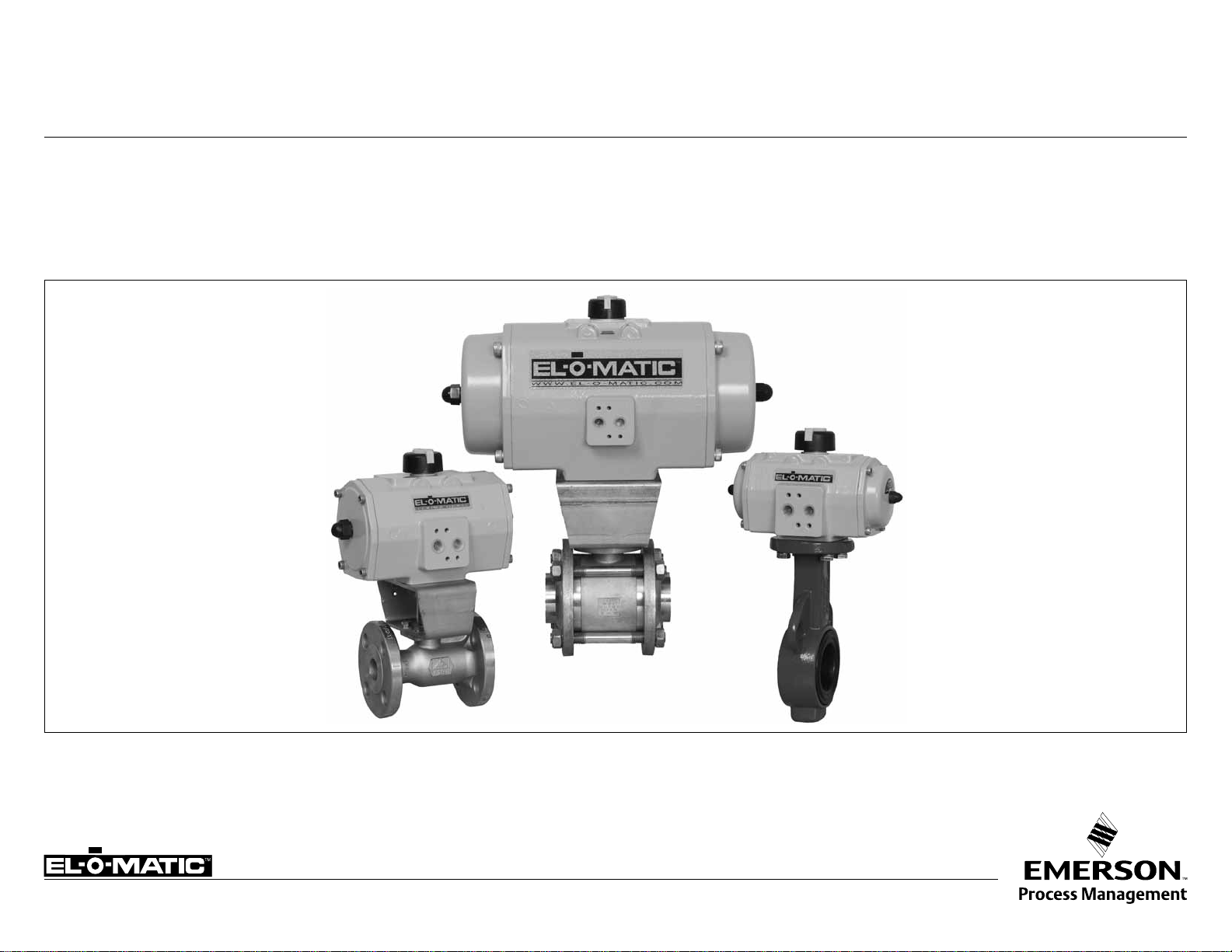
El-O-Matic E and P Series
Technical data pneumatic Rack and Pinion actuators
www.El-O-matic.com
Data sheet
A B
A B
A B
Sheet No.:
Date: June 2010
A1.102 Rev. B
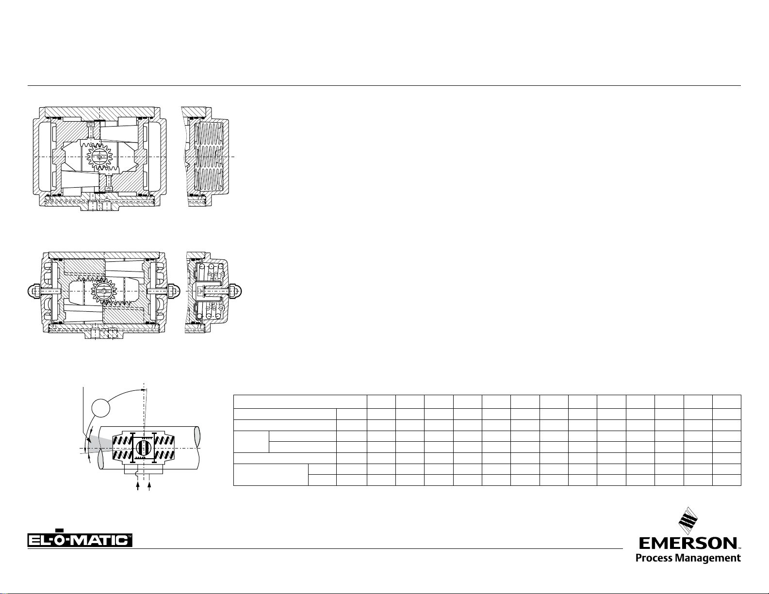
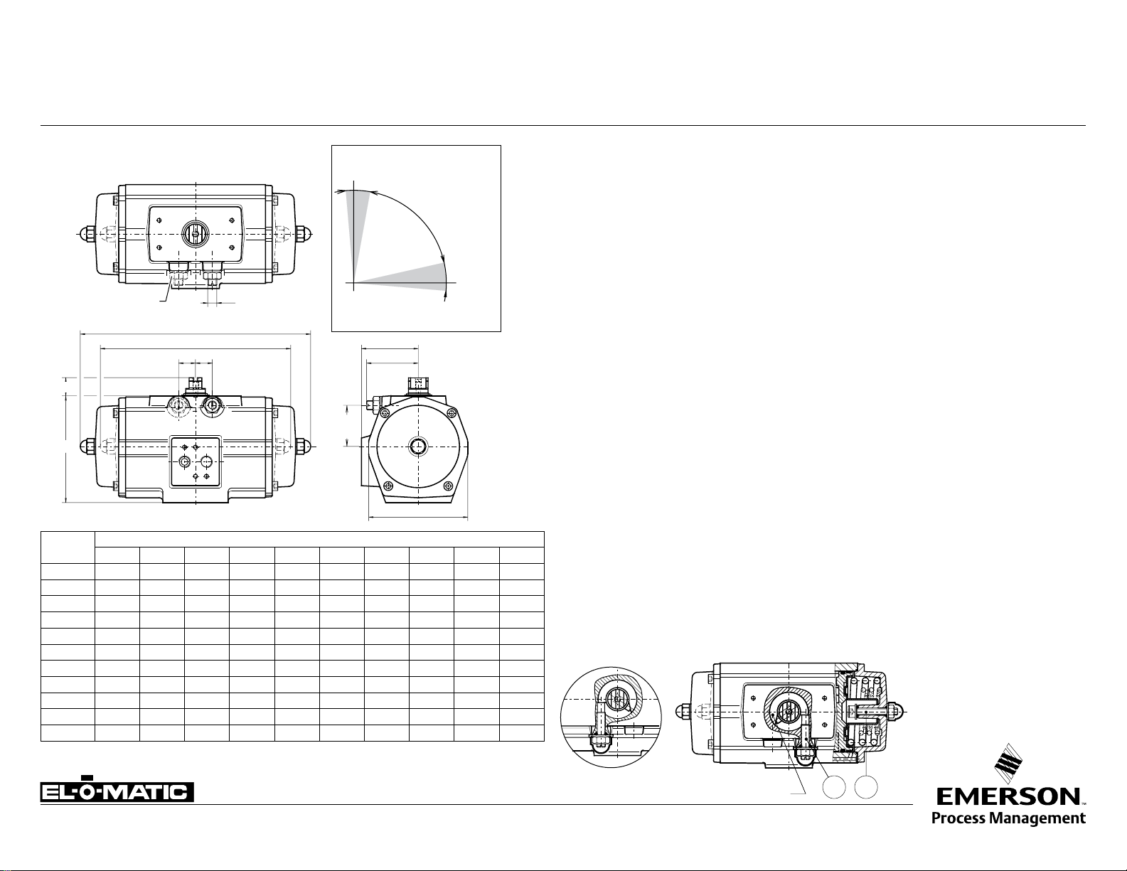
TECHNICAL DETAILS, STANDARD ACTUATOR E/P
P-series
PD = Double acting
E-series
ED = Double acting
11°
Adjustable
range*
91°
Open
*
only standard on E-Serie actuators
A B
A B
91.5°
A
PS = Spring return
ES = Spring return
-0.5° Closed
B
Specification
Pressure range : Double acting 20 to 120 psi
: Spring return 80 to 120 psi,, with max. spring set
40 to 120 psi, reduced spring
quantity
: 180° actuators 87 psi maximum
Torque : 1133 to 40,000 in.lb at 80psi supply
See torque datasheets 1.104.01 and 1.104.02
Operating media : Air, dry or lubricated and inert gasses
: For sub-zero applications take appropriate measures
Temperature : -4° to +176°F
European Directives
PED : All actuators are suiteable for use
with Group 2 gasses according to
Pressure Equippement Directive
97/23/EC
: Optional : actuators suiteable for
use with Group 1 gasses
ATEX : All basic actuators are suiteable
for use in hazardous area's
classified II 2 GD, zones 1 or 2
(Gasses) and 21 or 22 (Dust)
Lubrication : Factory lubricated for the normal life of the actuator
Construction : Suitable for indoor and outdoor installation
Finish : Polyester non-TGIC based powder coating
(see data sheet A4.204.01)
Rotation : 91.5° (-0.5° CW to 91° CCW)
Russian Approvals
El-O-Matic E and P series pneumatic actuators are
available with the GOST-R and Rostechnadzor (RTN)
approvals.
Double acting : Standard counter clockwise with port "A" pressurized
(code A, see data sheet A1.503 for other assembly
codes)
Spring return : Clockwise fail action
(code A, see data sheet A1.504 for other assembly
codes)
Note
1. Operating time is average with actuator under load
and solenoid valve fitted.
2. Air consumption is the actual free air volume at 1 atm.
3. Pressure is in barg.
Limit stops : Standard on E-series. Adjustable range 91°/80°
: Optional on P-series. See datasheet A1.501.01
: For double stroke adjustment. See datasheet
A1.501.05
ACTUATOR TYPE E12 E25 E40 E65 E100 E150 E200 E350 E600 E950 E1600 P2500 P4000
Bore inch
Stroke inch
Weight:
Operating time sec.
Air consumption at
1 atm (cu./in.)
Double acting lb.
Spring return lb.
port A stroke
port B stroke
1.8 2.2 2.8 3.1 3.6 4.1 4.3 5.7 6.9 7.9 9.1 11.8 12.8
0.5 0.6 0.7 0.9 1.0 1.2 1.5 1.5 1.7 2.0 2.5 2.2 3.2
1.3 2.9 4.0 5.3 6.8 10.5 12.8 23 43 58 94 125 191
1.5 3.7 5.3 7.9 10.1 15.2 20.1 37 61 85 145 194 291
0.4 0.5 0.7 1.1 1.2 1.8 2.3 3.6 4.5 5.4 6.9 7 12
3.1 6.1 9.8 20 21 45 49 110 177 287 445 488 824
3.7 6.7 13 22 30 40 61 116 189 299 488 568 1,068
www.El-O-matic.com
Copyright © Emerson Process Management. The information in this document is subject to change without notice.
Updated data sheets can be obtained from our website www.El-O-Matic.com or from your nearest Valve Automation Center USA: +1 813 319 0266 Europe: +31 74 256 10 10 Asia-Pacific: +65 6501 4600

Data sheet
Sheet No.:
Date: November 2010
A1.102.10 Rev. C
EL-O-MATIC BASIC PNEUMATIC ACTUATOR CONFIGURATION E/P
Single or Double action
ES
PS
or
= Single acting,
Actuator siz
E-series
0012 = E12 0025 = E25 0040 = E40 0065 = E65 0100 = E100 0150 = E150
0200 = E200 0350 = E 350 0600 = E600 0950 = E950 1600 = E1600
P-series
2500 = P2500 4000 = P4000
e
ED or PD
= Double acting
Valve flange
Metric Metric UNC/NPT
ISO 5211 DIN 3337 ISO 5211
M = D =
N = E = V =
O =
F =
U =
W =
Finish
Standard
CSR coating
CSR coating
(2
+ Aluminum pinion
(2
+ Stainless Steel pinion
(3
Limit stops
0 = No limit stops 1 = L1 One way limit stops 2 = Double Stroke Adjustment
Standard on P-series Standard on E-Series Standard on DSA-Series
Assemb
ly code
Code Action Rotation Mounting
A =
B =
C =
D =
ing to close clock wise in line with pipeline
Spr
Spring to close clock wise across pipeline
Spr
ing to open counter clock wise across pipeline
Spring to open counter clock wise in line with pipeline
Spring set E-serie Spring set P-serie
00 = Double acting actuator 00 = Double acting actuator
01 = Springset 1 04 = Springset 4 04 = Springset 4 10 = Springset 10
02 = Springset 2 05 = Springset 5 06 = Springset 6 12 = Springset 12
03 = Springset 3 06 = Springset 6 08 = Springset 8 14 = Springset 14
Future expansion
A = Standard
Default Insert
Size (in mm.)
- ISO or UNC 00 11 14 14 19 19 22 27 27 36 46 00 00
- DIN 00 11 14 14 17 17 22 22 27 36 46 00 00
(1
E12 E25 E40 E65 E100 E150 E200 E 350 E600 E950 E1600 P2500 P4000
See following data sheets
for more information
A1.104.01 / A1.104.02
A1.103.106 / A1.103.073 /
A1.103.102 / A1.103.103
A1.101.30 / A1.101.33 /
A4.204.01
A1.501.01/
A1.501.05
A1.503/
A1.504
A1.104.02
A1.103.073
A1.103.106
A1.103.120
Visual Indication Code
D = Disk K = Knob N = No visual indication
A1.101.70 / A1.101.71
ES 0040.M 1 A 05 A.14 N 1
Temperature range
0 = Standard TS: 80°C (176°F) -20°C ( -4°F)
1 = High temp TS: 120°C (248°F) -20°C ( -4°F)
2 = Low temp TS: 80°C (176°F) -40°C (-40°F)
(1
Actuators E12, P2500 and P4000 have no inserts. They have have a inner square the shaft
180° actuators are not covered by this configuration matrix.
(2
CSR Coating not possible in combination with Double Stroke Adjustment limit stops (DSA series).
(3
Stainless Steel Pinion not possible in combination with Double Stroke Adjustment limit stops (DSA series).
www.El-O-matic.com
Copyright © Emerson Process Management. The information in this document is subject to change without notice.
Updated data sheets can be obtained from our website www.El-O-Matic.com or from your nearest Valve Automation Center USA: +1 813 319 0266 Europe: +31 74 256 10 10 Asia-Pacific: +65 6501 4600
Data sheet
TM
B
A
C
D
Sheet No.:
Date: November 2009
A1.501.01 Rev. A
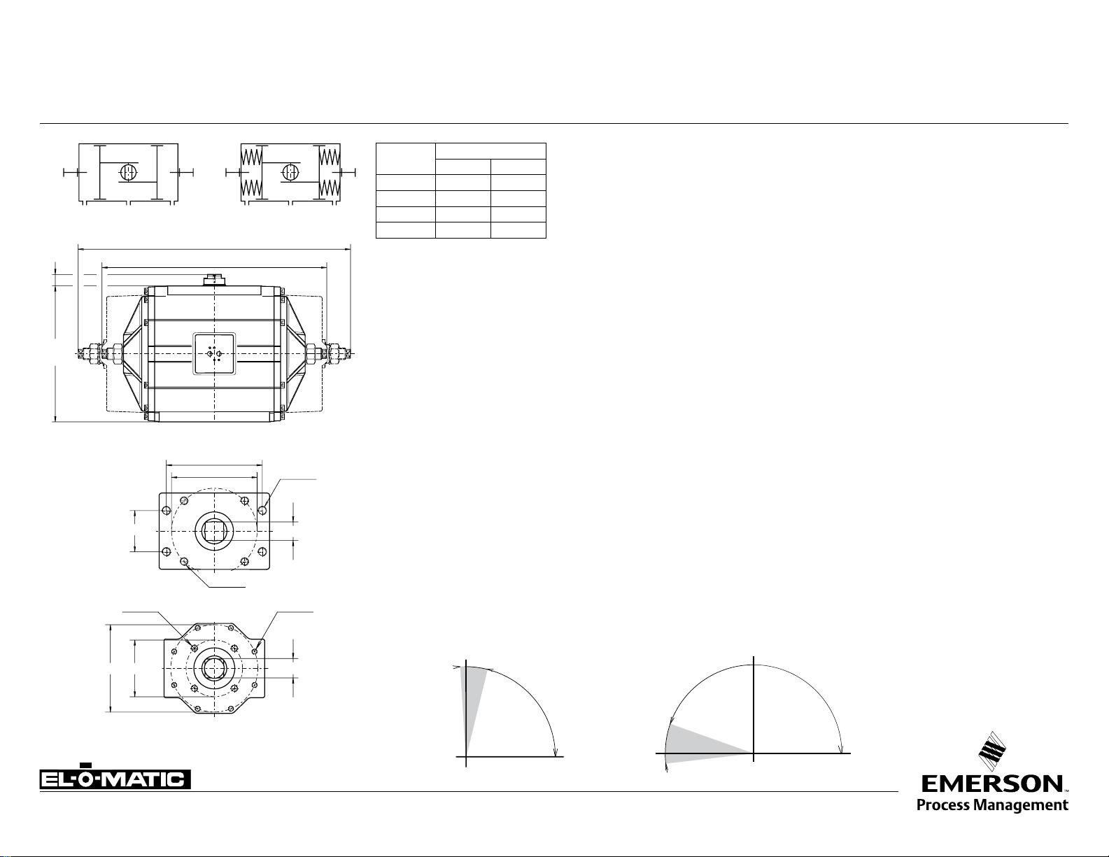
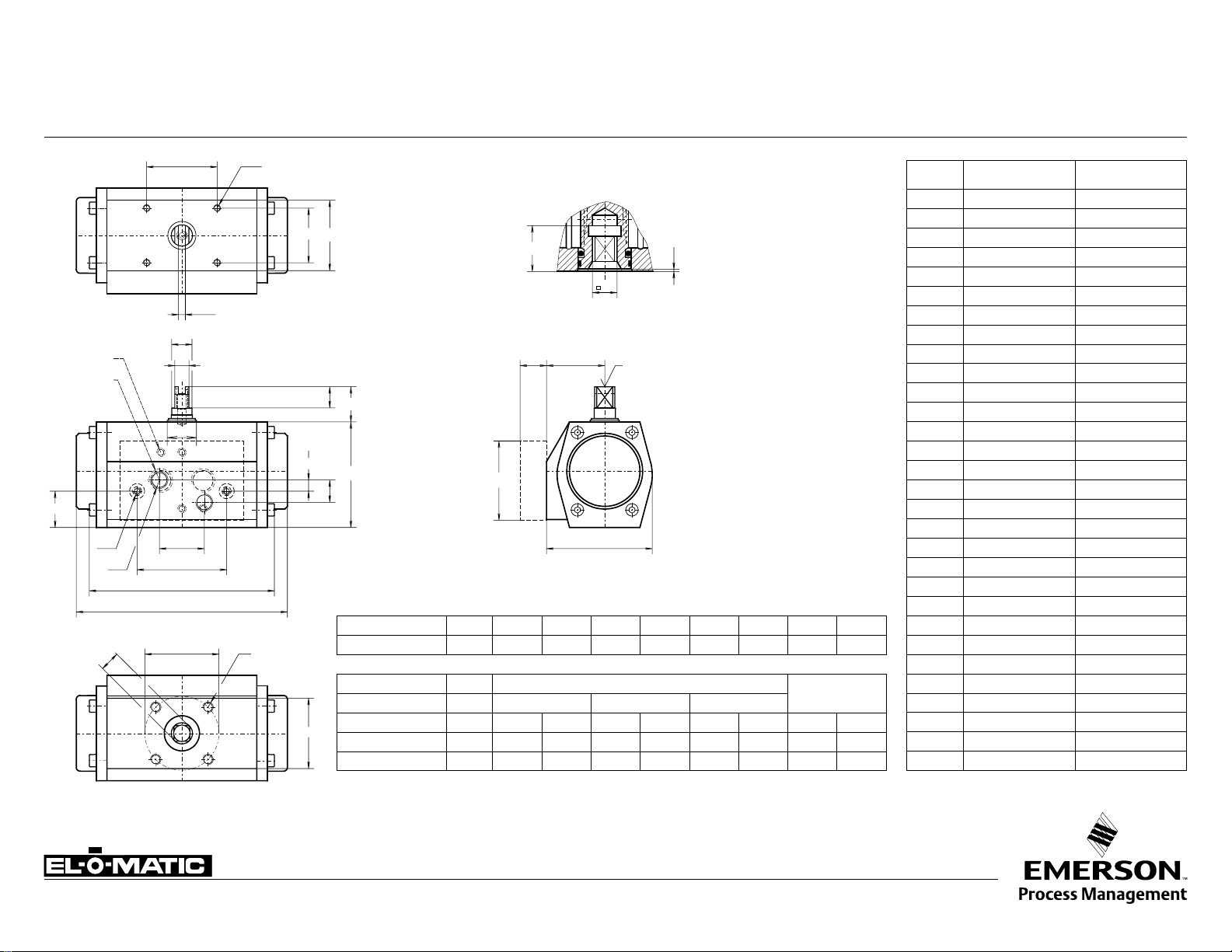
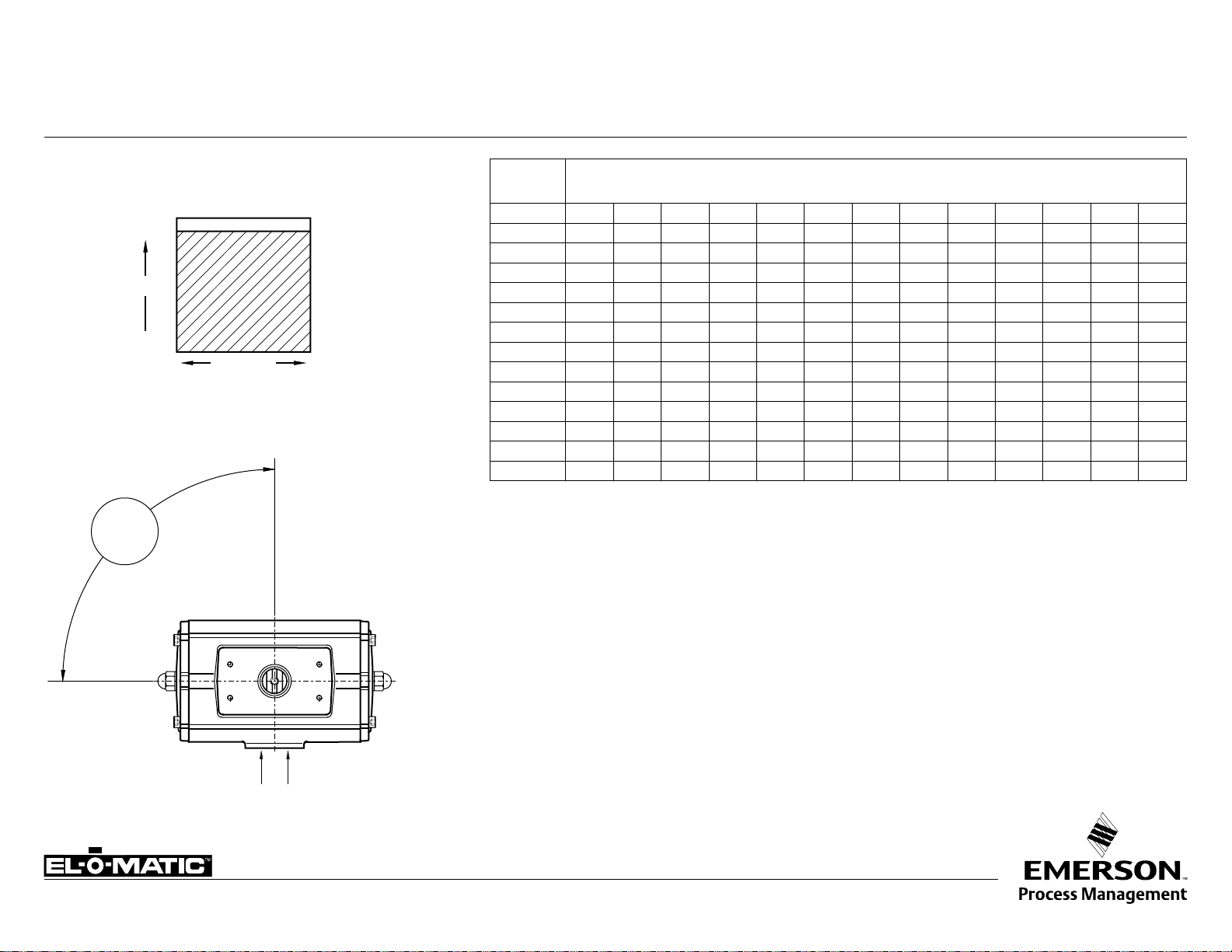
EL-O-MATIC ACTUATOR WITH ONE WAY LIMIT STOPS L1/LF
Description
Actuators with one way adjustable limit stops are used where the maximum opening (or closing)
position of the valve needs to be reduced. For instance to adjust the maximum capacity of a
remote operated valve.
Also actuators with 180° rotation are available with these stops.
Operation
DOUBLE ACTING
SPRING RETURN
Dim.
in inch
A
B
C
D
ACTUATOR TYPE
P2500 P4000
22.8 27.9
31.3 45.4
14.0 15
1.2 1.2
Stop screws are fitted to both endcaps and the screw length is such that adjustment is possible
through the specified rotation of the actuator.
The modified endcap is machined for -0.5° to +93° rotation for all P-series models.
Identification
“L1” is added to the basic part number i.e. PD2500-L1
Specification:
Pressure : Up to 120 PSI
Media : Air, dry or lubricated or non-corrosive gas
Torque (90°) : Data sheet A1.104.01 - A1.104.04
(180°) : Data sheet P-serie A1.204.01 and A1.204.02
Other dimensions : Data sheet A 1.103.XXX (90°)
: Data sheet A 1.203.011 (180°)
Temperature : -4.0° to +176°F
9.236
6.496
5/8"-11x.98
Adjustable range : 80°-93°(90°) or 160°-186° (180°)
Adjustable position (see data sheet A1.503 or A1.504)
code position
A Valve open (spring to close)
3.827
1.811
P2500
B Valve open (spring to close)
C Valve closed (spring to open)
D Valve closed (spring to open)
Note:
10x1.14
3/4"-10x1.14
5/8"-11x.98
1) Can be provided with extra long screws for full range adjustment
(identification: PD2500-LF)
2) This option in combination of a manual override gearbox is redundant
6.496
3/4"-
2.16510.000
P4000
Open
3° 10°
Adjustable range
90° actuator
Adjustable range
180° actuator
Note: Do not adjust under pressure
-20°
Closed
www.El-O-matic.com
Copyright © Emerson Process Management. The information in this document is subject to change without notice.
Updated data sheets can be obtained from our website www.El-O-Matic.com or from your nearest Valve Automation Center USA: +1 813 319 0266 Eur ope: +31 74 256 10 10 Asia-Pacific: +65 6501 4600
+6°
Open
Closed
Data sheet
TM
E
Gmax.
F
WO
V
H
max.
+1° -15°
+0.5°
-15°
Sheet No.:
Date: November 2009
A1.501.03 Rev. A
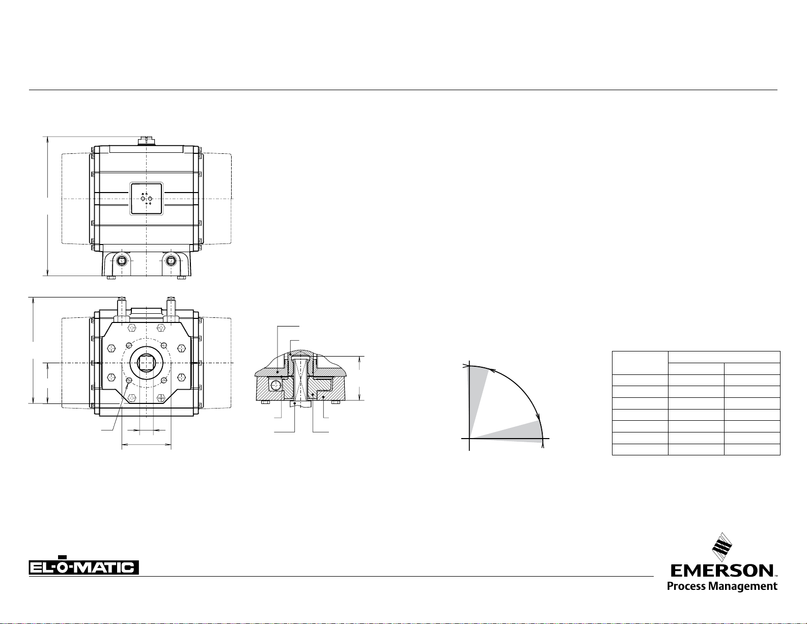
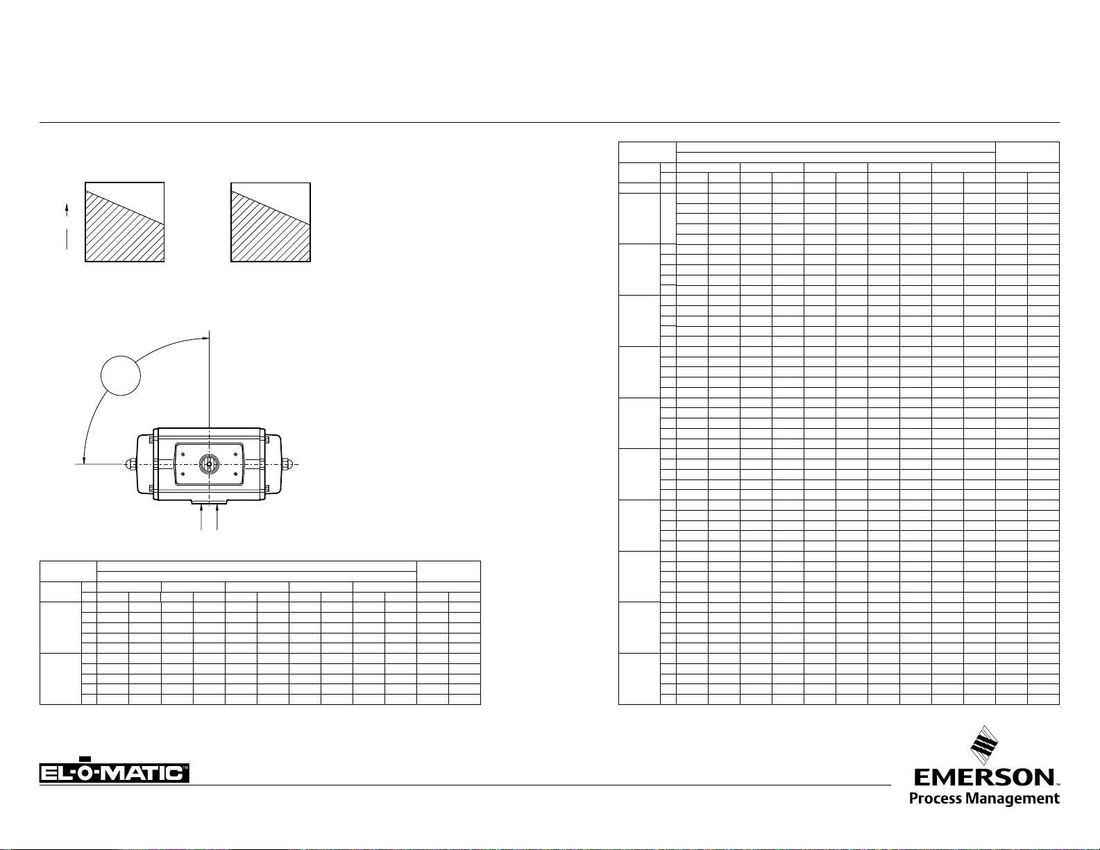
LIMIT STOP PLATE DIMENSIONS LS 420
Description
These limit stop plates are used when precise control is required for both end of stroke positions.
It is possible to adjust 15° of both ends of the standard stroke.
Construction
The complete stop plate assembly may be added to the 90° P- series actuators.
The assembly is normally sandwiched between the actuator and mounting surface of the valve
or bracket. Bearing rings are used at both surfaces to provide a long life expectancy.
The unit is assembled with a drive adaptor which passes through the stop plate, into the square
actuator and provides the coupling between the two components.
This drive adaptor normally also accommodates the coupling of the valve stem.
Identification
"LS420" is added to the basic part number i.e. PD2500-LS420
Other dimensions
See data sheet A1.103.xxx
Option
Version for 180° or DIN-standard actuator
Actuator base
Drive shaft
Cover plate
Drive adaptor
Note: Cover plate only in combination with P2500
www.El-O-matic.com
Copyright © Emerson Process Management. The information in this document is subject to change without notice.
Updated data sheets can be obtained from our website www.El-O-Matic.com or from your nearest Valve Automation Center USA: +1 813 319 0266 Eur ope: +31 74 256 10 10 Asia-Pacific: +65 6501 4600
Housing limit stop
Cam
Open
Adjustable range
90° actuators
Closed
Dim.
in inches
E
F
G
H
O
V
W
ACTUATOR TYPE
P2500 P4000
18.3 19.3
5.3 5.3
12.7 12.7
5.1 5.6
1.8 2.2
165 165
M20x30 M20x30
Data sheet
TM
Y
A
B
C
H
I
X
J
1
LL
D
3° 10°
3°
15°
1
2
Sheet No.:
Date: November 2009
A1.501.05 Rev. A
EL-O-MATIC ACTUATOR WITH DOUBLE STROKE ADJUSTMENT DSA
Open
stopscrew (2)
adjustable
range
Description
Actuators with double stroke adjustment are normally used for high performance butterfly valves
where a fine adjustment is required for the closed position. In this version adjustment is provided
at the end of the opening and closing stroke positions. DSA actuators may be double acting or
spring return, though are normally used as spring return (fail close) actuators.
Operation
The closed position is adjusted by means of the stop-screw (1) located in the actuator body and
for the open position by the stop-screws (2) in the actuator end caps.
Factory option:
Fail to Open
Closed
stopscrew (1)
Identification
See data sheet A1.102.10
Specification
Pressure : Up to 120 psi
Operating media : Air, dry or lubricated or non-corrosive gas
Torque (90°) : Data sheet A1.104.01 - A1.104.02
Rotation -
- Spring return : Clock-wise on air failure.
- Double acting : Counter clock-wise with port “A” pressurised.
Other dimensions : Data sheet A1.103.XXX
Temperature : -4° to +176° F
Adjustable range : Closed position (1), -3° - 15°
Open position (2), 80° - 93°
Dim.
in inch.
A DA
B SR
C
D
H
J1
L
Y
X
X max.
E25 E40 E65 E100 E150 E200 E350 E600 E950 E1600
6.26 7.09 7.83 8.70 10.00 11.14 12.01 15.35 17.32 20.47
6.77 8.03 9.80 10.51 12.20 14.17 15.24 18.90 20.94 25.24
3.15 3.66 4.13 4.65 5.51 5.63 7.13 8.66 10.20 11.69
0.79 0.79 0.79 0.79 0.79 0.79 0.79 1.18 1.18 1.18
2.91 3.39 3.86 4.25 4.76 5.04 6.81 8.15 9.09 264.00
I
1.81 2.01 2.26 2.48 2.76 2.87 3.71 4.45 4.96 5.59
1.11 1.38 1.57 1.72 1.92 2.12 2.85 3.50 4.03 4.50
0.45 0.61 0.61 0.73 0.97 0.97 0.97 1.63 1.63 1.87
1/4"-20 5/16"-18 5/16"-19 3/8"-16 3/8"-16 1/2"-13 1/2"-13 5/8"-11 5/8"-11 3/4"-10
1.42 1.63 1.63 1.99 2.36 2.46 2.85 4.02 4.02 4.31
1.63 1.91 1.91 2.30 2.64 2.91 3.31 4.51 4.51 4.88
Actuator type
Note
1) Can be provided with extra long end-cap stop screws for full range adjustment of the “open”
position.
2) This DSA option is not required on actuators fitted with manual override gearboxes, as MO
gearboxes already incorporate this function.
Important
1) "Fail open" is factory option.
2) When assembled for “fail open” operation (code D; see data sheet A1.504), both stop-screws
(1) and (2) will adjust the closed position. There is no adjustment for the open position!
www.El-O-matic.com
Copyright © Emerson Process Management. The information in this document is subject to change without notice.
Updated data sheets can be obtained from our website www.El-O-Matic.com or from your nearest Valve Automation Center USA: +1 813 319 0266 Eur ope: +31 74 256 10 10 Asia-Pacific: +65 6501 4600
Factory option:
"Fail open"
Stroke adjustment cam
Data sheet
Sheet No.:
Date: May 2011
A1.103.106 Rev. D
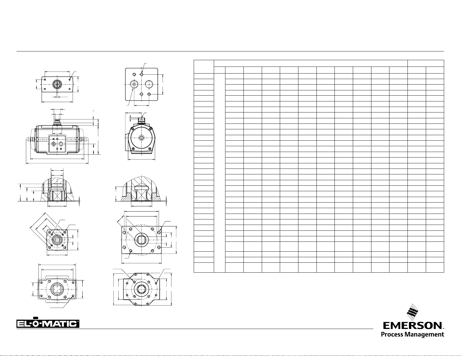
DIMENSION SHEET STANDARD ACTUATOR - ISO E/P
U1 R1
E-series
M1
M2
M3
øV1
øV
+0.02
0
øP
E25-E950
E1600
T1
S1
E
F
E2
A
B
øP2
øP1
øK
S
S
9.236
0.16
W
UNC 10-24x.31
±0.02
N
W1
R
O
UNC 10-24x.31
B
1.26
A
0.16
0.95
I
M6x.47
H
1/4”NPT
G
D
C
J
P-series
M1
W
øP
+0.02
øK
T
0
øV
W
S
±0.02
N
W2
O
U
P2500
W1
R
Dim.
in inch
A DA
B SR
C
D
E
E2
F
G
H
I
J
K
M1
M2
M3
N
O max.
O min.
P
P1
P2
R
R1
R2
S
S1
T1
U1
V
W
V1
W1
E 12 E 25 E 40 E 65 E100 E150 E200 E 350 E600 E950 E1600 P2500 P4000
For E12 dimensions see data sheet A1.103.102
6.26 7.09 7.83 8.70 10.00 11.14 12.01 15.24 16.69 20.31 14.88 19.76
6.77 8.03 9.80 10.51 12.20 14.17 15.24 18.78 20.35 25.08 22.44 32.83
3.15 3.66 4.13 4.65 5.51 5.63 7.13 8.66 10.20 11.69 14.02 14.96
0.79 0.79 0.79 0.79 0.79 0.79 0.79 1.18 1.18 1.18 1.18 1.18
0.63 0.87 0.87 0.87 1.42 1.42 1.42 2.17 2.17 2.52 2.17 2.52
0.91 1.18 1.18 1.18 1.77 1.77 1.77 2.56 2.56 2.95 2.56 3.15
0.39 0.55 0.55 0.55 0.75 0.75 0.75 1.42 1.42 1.42 1.42 1.42
0.47 0.47 0.47 0.47 0.47 0.47 0.47 0.39 0.39 0.39 0.39 0.39
2.91 3.39 3.86 4.25 4.76 5.04 6.81 8.15 9.09 10.43 13.78 14.96
1.81 2.09 2.26 2.48 2.76 2.87 3.71 4.45 4.96 5.59 7.28 7.87
1.26 1.32 1.54 1.59 1.59 1.99 2.85 3.33 4.15 4.74 7.01 7.48
0.94 1.30 1.30 1.50 2.17 2.17 2.17 2.68 2.95 3.74 3.35 4.72
1.36 1.36 1.36 1.36 1.97 1.97 1.97 2.05 2.52 3.23 2.60 3.03
- - - 1.06 - 1.46 1.46 - - - - -
0.669 0.669 0.669 0.787 0.787 1.161 1.161 1.161 1.949 2.303 - -
0.04 0.04 0.04 0.06 0.04 0.06 0.06 0.06 0.06 0.06 0.12 0.06
0.437 0.556 0.556 0.753 0.871 0.871 1.068 1.068 1.424 1.817 1.817 2.173
0.433 0.551 0.551 0.748 0.866 0.866 1.063 1.063 1.417 1.811 1.811 2.165
0.555 0.713 0.713 0.992 1.110 1.110 1.425 1.425 1.898 2.370 2.370 2.843
0.555 0.713 0.831 0.909 1.303 1.303 1.303 1.437 1.909 2.382 - -
- - - 0.988 1.264 1.264 1.264 - - - - -
2.05 2.56 2.76 2.76 3.39 3.54 4.49 4.88 5.12 6.06 6.69 6.69
1.97 1.97 1.97 2.36 2.36 2.36 2.36 3.54 3.54 4.92 6.30 6.30
- - - - - - - - - 5.20 - 10.31
2.05 2.56 2.76 2.76 3.62 3.54 4.49 4.88 5.59 11.02 11.42 11.42
3.94 3.94 3.94 3.94 3.94 3.94 3.94 6.69 6.69 8.27 9.65 9.65
3.150 3.150 3.150 3.150 3.150 3.150 3.150 5.118 5.118 5.118 5.118 5.118
1.181 1.181 1.181 1.181 1.181 1.181 1.181 1.181 1.181 1.181 1.181 1.181
F03 F05 F05 F05 F07 F07 F07 F10 F10 F16 F16 F16
1.417 1.969 1.969 1.969 2.756 2.756
10-24
1/4"-20
x.31"
F05 F07 F07 F07 F10 F10 F10 F12 F14 - - F25
1.969 2.756 2.756 2.756 4.016 4.016 4.016 4.921 5.512 - - 10.000
1/4"-20
5/16"-18
x.39"
x.39"
x.39"
1/4"-20
x.39"
5/16"-18
x.39"
Actuators E-series P-series
1/4"-20
x.39"
5/16"-18
x.39"
5/16"-18
x.39"
3/8"-16
x.63"
5/16"-18
x.39"
3/8"-16
x.63"
2.756 4.016 4.016 6.496 6.496 6.496
5/16"-18
3/8"-16
x.39"
x.63"
3/8"-16
x.63"
1/2"-13
x.79"
3/8"-16
x.63"
5/8"-11
x.98"
3/4"-10
x1.14"
- -
3/4"-10
x1.14"
3/4"-10
x1.14"
"5/8""-11
x.98"
3.827
R2
øV
R
R2
Note
øV1
1. Flange and square drive to ISO 5211
5/8”-11
x .98”
P4000
2. Top and solenoid flange to VDI/VDE 3845 (NAMUR)
3. For P-series actuators with limit stops see A1.501.01
www.El-O-matic.com
Copyright © Emerson Process Management. The information in this document is subject to change without notice.
Updated data sheets can be obtained from our website www.El-O-Matic.com or from your nearest Valve Automation Center USA: +1 813 319 0266 Europe: +31 74 256 10 10 Asia-Pacific: +65 6501 4600
Data sheet
TM
T
W2
U
R1
0.16
UNC10-24x .31
1/4"
E
F
G
D
K1
K
C
E2
W1
X
L
L1
A
B
J
øP
+0.02
0
øV
R
W
YI
H
1.77
0.59
M
N
±0.02
O
Sheet No.:
Date: November 2009
A1.103.102 Rev. A
DIMENSION SHEET ACTUATOR ISO E12 (90°/180°)
Dim. in
Inches
A ED
B ES
C
D
E
E2
F
G
H
I
DOUBLE ACTING TORQUE (ED)
Pressure psi 40 50 60 70 80 90 100 120
Torque 90°/180° (in.lb.)
59 74 89 104 119 134 149 179
SINGLE ACTING TORQUE (ES)
Pressure psi 60 80 100
Position - start end start end start end start end
Torque 90° (in.lb.)
Torque 180° (in.lb.)
48 23 80 55 112 87 64 41
49 25 81 57 112 88 63 40
Air stroke
Spring
stroke
J
K
K1
L
L1
M
N
Omax.
Omin.
P
R
R1
T
U
V
W
W1
W2
X
Y
90° 180°
4.06 6.10
4.65 8.50
2.36 2.36
0.79 0.79
0.63 0.63
0.91 0.91
0.39 0.39
0.47 0.47
2.36 2.36
1.30 1.30
0.83 0.83
0.50 0.50
0.25 0.25
1.00 1.00
2.00 2.00
0.65 0.65
0.039 0.039
0.358 0.358
0.354 0.354
0.476 0.476
1.57 1.57
1.57 1.57
1.57 1.57
1.22 1.22
1.654 1.654
10-24 UNCx.24" 10-24 UNCx.24"
10-24 UNCx.24" 10-24 UNCx.24"
10-24 UNCx.24" 10-24 UNCx.24"
1/8"NPT 1/8"NPT
M6x.48 M6x.48
www.El-O-matic.com
Copyright © Emerson Process Management. The information in this document is subject to change without notice.
Updated data sheets can be obtained from our website www.El-O-Matic.com or from your nearest Valve Automation Center USA: +1 813 319 0266 Eur ope: +31 74 256 10 10 Asia-Pacific: +65 6501 4600
Data sheet
Ø P2
Ø P1
M1
M2
Sheet No.:
Date: May 2011
A1.103.200 Rev. B
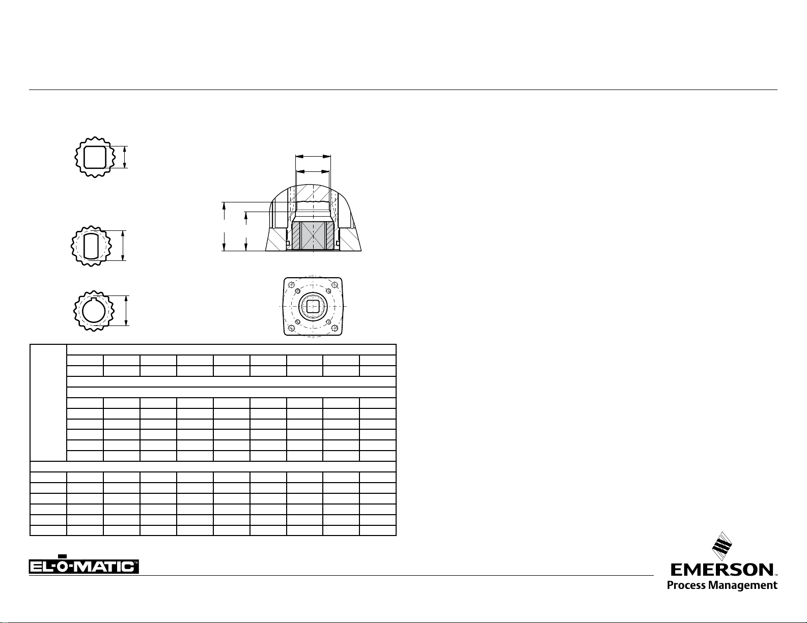
DRIVE INSERTS FOR EL-O-MATIC ACTUATORS E
Standard available
insert shapes
sq Max.
Optional available
insert shapes
D Max.
D Max.
Standard inserts with inner-square-dimensions per actuator type
E25 E40 / E65 E100 E150 E200 E350 E600 E950 E1600
0.433 0.551 0.748 0.866 0.866 1.063 1.063 1.417 1.811
Optional insert dimensions
0.354 0.394 0.472 0.551 0.551 0.551 0.551 0.866
0.394 0.472 0.551 0.630 0.630 0.630 0.630
0.63 0.669 0.669 0.669 0.669
0.748 0.748 0.748 0.748
0.945 0.945 0.866 0.866
1.063 1.063 0.945 0.945
Maximum insert dimensions
M1 1.36 1.36 1.36 1.97 1.97 1.97 2.05 2.52 3.23
M2 - - 1.06 1.46 1.46 1.46 - - P1 0.71 0.71 0.91 1.26 1.26 1.26 1.44 1.91 2.38
P2 - - 0.99 1.43 1.43 1.43 - - -
SQ max. 0.630 0.630 0.748 1.063 1.063 1.063 1.063 1.417 1.811
D max. 0.827 0.827 0.929 1.323 1.323 1.323 1.323 1.772 2.362
Insert mounting
acc. ISO 5211
Description
Most of the El-O-Matic actuators are fitted with drive inserts. This enables actuators to be
directly mounted onto suitable valves and eliminates the need for a bracket and coupling type
mounting kit. The use of direct mounts significantly cuts the cost of the valve/actuator assembly.
Standard actuators are fitted with square drive inserts in accordance with ISO 5211 (or DIN
3337), but a wide variety of other inserts are also available. Special inserts may have oversize or
undersize squares, double-D and shaft key way forms.
Drive inserts can be supplied on factory built actuators or as loose items and are easily
replaceable at distributor or end user level.
Where direct mounts are not possible, for instance on valves with exposed grand packing, the
use of inserts often simplifies the design of the mounting kit.
Material : Aluminum alloy
Finish : Anodized
The following actuator types do not have inserts.
- E12,
- P2500 and P4000
- 180° actuators
These actuators have inner square directly in the bottom of the pinion. See the following data
sheets for more information :
E12 ISO5211 A1.103.102
P2500/P4000 ISO 5211 A1.103.106
180° ISO 5211 A1.203.011
www.El-O-matic.com
Copyright © Emerson Process Management. The information in this document is subject to change without notice.
Updated data sheets can be obtained from our website www.El-O-Matic.com or from your nearest Valve Automation Center USA: +1 813 319 0266 Europe: +31 74 256 10 10 Asia-Pacific: +65 6501 4600
Data sheet
91.5°
-0.5°
91°
AB
Sheet No.:
Date: January 2010
A1.104.01 Rev. B
DOUBLE ACTING ACTUATOR TORQUE (In.lb.) 90°
DOUBLE ACTING TORQUE
Start End
Torque
Rotation
CLOSED
Actuator
Type Size 30 35 40 45 50 55 60 70 75 80 90 100 120
ED 12
ED 25
ED 40
ED 65
ED 100
ED 150
ED 200
ED 350
ED 600
ED 950
ED 1600
PD 2500
PD 4000
43.9 51.4 58.9 66.4 73.9 81.4 88.9 104 111 119 134 149 179
81.4 95.3 109 123 137 151 165 193 206 220 248 276 332
153 179 205 231 257 283 309 361 387 413 466 518 622
233 272 312 352 392 431 471 551 590 630 709 789 948
344 402 461 520 578 637 696 813 872 930 1048 1165 1400
551 645 739 833 927 1021 1115 1303 1397 1491 1680 1868 2244
754 883 1011 1140 1269 1398 1527 1784 1913 2042 2299 2557 3072
1310 1534 1757 1981 2205 2428 2652 3100 3323 3547 3994 4442 5337
2226 2606 2986 3366 3747 4127 4507 5267 5647 6028 6788 7548 9069
3323 3890 4458 5025 5593 6160 6728 7862 8430 8997 10132 11267 13537
5493 6431 7369 8307 9245 10183 11121 12998 13936 14874 16750 18626 22379
8774 10273 11825 13270 14768 16267 17847 20858 22363 23869 26880 29891 35912
14874 17414 19962 22495 25035 27576 30127 35210 37751 40293 45375 50458 60623
Torque of double acting actuators (in In.lb)
Supply pressure (psi)
Note
1. Emerson Process Management recommends that the valve manufacturer supply the maximum required torque
values (Including any adjustments or suggested safety factors for valve service conditions or application).
Additionally, the valve manufacturer must identify at which position(s) and direction(s) of rotation
(Counter Clock Wise or Clock Wise) these maximum requirements occur.
2. If in doubt, or you require any assistance with sizing actuators, do not hesitate to contact your
nearest Emerson's Valve Automation Division representative.
3 Pressure on port "A" opens the actuator*
4 The actuator is shown in closed position*
(* code A, data sheet A1.503)
OPEN
www.El-O-matic.com
Copyright © Emerson Process Management. The information in this document is subject to change without notice.
Updated data sheets can be obtained from our website www.El-O-Matic.com or from your nearest Valve Automation Center USA: +1 813 319 0266 Eur ope: +31 74 256 10 10 Asia-Pacific: +65 6501 4600
Data sheet
91.5°
C
F
D E
-0.5°
91°
AB
Sheet No.:
Date: January 2010
A1.104.02 Rev. B
SPRING RETURN ACTUATOR TORQUE (In.lb.) 90°
Start
Torque
Springset
Actuator
Type
PS 2500
PS 4000
C
OPEN
SINGLE ACTING TORQUE
D
End
Rotation
Counter Clockwise
SPRING STROKEAIR STROKE
E
Start
F
End
Rotation
Clockwise
Note
1. Emerson Process Management
recommends that the valve manufacturer
supply the maximum required torque values
(Including any adjustments or suggested
safety factors for valve service conditions or
application).
Additionally, the valve manufacturer must
identify at which position(s) and direction(s)
of rotation (Counter Clock Wise or Clock
Wise) these maximum requirements occur.
2. If in doubt, or you require any assistance
with sizing actuators, do not hesitate to
CLOSED
contact your nearest Emerson's Valve
Automation Division representative.
3 Pressure on port "A" opens the actuator*
4 The actuator is shown in closed position*
(* code A, data sheet A1.504)
nr.
40 60 80 100 120 (lbf/in)
C D C D C D C D C D E F
6 6881 4278 12875 10273 18869 16267 24863 22261 30858 28255 7013 4401
8 5251 1781 11245 7775 17239 13769 23233 19764 29228 25758 9351 5868
10 - - 9615 5278 15609 11272 21603 17266 27597 23260 11689 7335
12 - - 7985 2780 13979 8774 19973 14768 25967 20763 14026 8803
14 - - - - 12349 6277 18343 12271 24337 18265 16364 10270
6 11701 7310 21862 17472 32024 27633 42185 37795 52347 47956 11835 7429
8 8949 3096 19111 13257 29272 23419 39434 33580 49595 43742 15780 9905
10 - - 16359 9042 26521 19204 36682 29365 46844 39527 19725 12381
12 - - 13608 4828 23770 14989 33931 25150 44093 35312 23670 14857
14 - - - - 21018 10774 31180 20936 41341 31097 27615 17333
Air Stroke (lbf/in)
SUPPLY PRESSURE (in PSI)
Spring Stroke
Actuator
Type
ES 12
ES 25
ES 40
ES 65
ES 100
ES 150
ES 200
ES 350
ES 600
ES 950
ES 1600
Springset
nr.
40 60 80 100 120 (lbf/in)
C D C D C D C D C D E F
2 - - 48 24 80 55 111 87 143 119 63 40
71 44 130 103 189 162 248 221 306 280 62 39
2
48 8 107 67 166 126 225 185 284 244 94 59
3
4
- - 85 31 144 90 203 149 262 208 125 78
5
- - - - 121 54 180 113 239 172 156 98
6
- - - - 99 18 158 77 217 136 188 117
2 133 82 243 193 354 303 464 414 575 524 117 73
3 91 15 201 125 312 236 422 346 533 457 176 110
4 - - 159 58 270 169 380 279 491 390 234 146
5 - - - - 228 101 338 212 449 322 293 183
6 - - - - 185 34 296 144 406 255 351 220
2 196 117 365 285 533 454 701 622 870 790 186 117
3 129 10 297 178 466 347 634 515 802 683 279 176
4 - - 230 71 398 240 567 408 735 576 372 234
5 - - - - 331 133 500 301 668 470 465 292
6 - - - - 264 26 432 194 601 363 558 351
2 303 192 552 441 801 690 1050 939 1299 1188 258 161
3 211 44 460 293 709 542 958 791 1206 1039 387 242
4 - - 367 144 616 393 865 642 1114 891 516 323
5 - - - - 523 245 772 494 1021 743 646 403
6 - - - - 430 96 679 345 928 594 775 484
2 485 297 884 696 1283 1094 1681 1493 2080 1892 423 259
3 337 54 735 453 1134 852 1533 1250 1931 1649 634 388
4 - - 587 210 985 609 1384 1007 1783 1406 845 517
5 - - - - 837 366 1235 764 1634 1163 1056 647
6 - - - - 688 123 1087 522 1485 920 1268 776
2 656 406 1202 952 1747 1498 2293 2043 2838 2589 579 362
3 448 74 994 619 1539 1165 2085 1710 2631 2256 868 542
4 - - 786 287 1332 832 1877 1378 2423 1924 1158 723
5 - - - - 1124 500 1669 1045 2215 1591 1447 904
6 - - - - 916 167 1462 713 2007 1258 1736 1085
2 1105 684 2053 1632 3001 2580 3949 3528 4897 4476 1025 658
3 727 95 1675 1043 2623 1991 3571 2939 4519 3887 1537 987
4 - - 1297 455 2245 1403 3193 2351 4141 3299 2049 1317
5 - - - - 1866 814 2814 1762 3762 2710 2561 1646
6 - - - - 1488 225 2436 1173 3384 2121 3074 1975
2 1920 1183 3531 2794 5142 4405 6753 6016 8364 7628 1723 1082
3 1298 193 2909 1804 4520 3415 6131 5026 7742 6637 2585 1624
4 - - 2287 814 3898 2425 5509 4036 7120 5647 3446 2165
5 - - - - 3276 1434 4887 3046 6498 4657 4308 2706
6 - - - - 2654 444 4265 2055 5876 3666 5169 3247
2 2898 1777 5303 4182 7708 6587 10113 8992 12518 11397 2563 1587
3 1986 304 4391 2709 6796 5114 9201 7519 11606 9924 3844 2381
4 - - 3479 1236 5884 3641 8288 6046 10693 8451 5125 3175
5 - - - - 4971 2168 7376 4573 9781 6978 6407 3968
6 - - - - 4059 695 6464 3100 8869 5505 7688 4762
2 4765 2988 8741 6964 12716 10939 16692 14915 20668 18890 4193 2646
3 3244 578 7220 4554 11196 8530 15171 12505 19147 16481 6289 3970
4 - - 5699 2145 9675 6120 13650 10096 17626 14071 8385 5293
5 - - - - 8154 3711 12129 7686 16105 11662 10481 6616
6 - - - - 6633 1301 10608 5277 14584 9252 12578 7939
Air Stroke (lbf/in)
SUPPLY PRESSURE (in PSI)
Spring Stroke
www.El-O-matic.com
Copyright © Emerson Process Management. The information in this document is subject to change without notice.
Updated data sheets can be obtained from our website www.El-O-Matic.com or from your nearest Valve Automation Center USA: +1 813 319 0266 Eur ope: +31 74 256 10 10 Asia-Pacific: +65 6501 4600
Data sheet
TM
Sheet No.:
Date: November 2009
A1.101.33 Rev. A
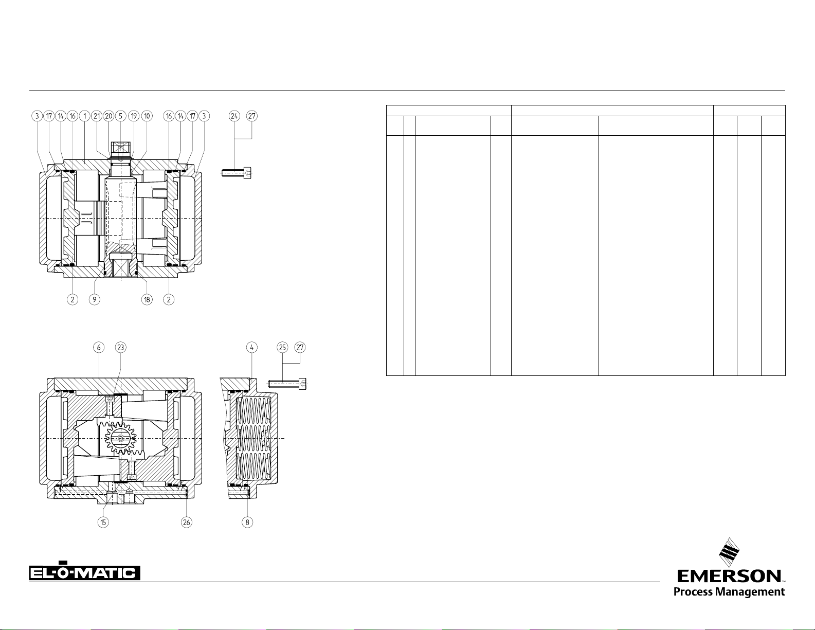
CONSTRUCTION, PARTS AND MATERIALS E-SERIE ACTUATORS E
Optional center-plate
Notes
1 Hard anodized
aluminum alloy:
AlZnMgCu1.5,
DIN 1725/1
2 Deltatone Coating
3 Anodized
4 Zinc plated and
passivated
5 CSR Coating
(see 4.204.02)
6 Stainless Steel
Sandvic 1802, SS2382
7 Stainless Steel
X35CrM017
8 No insert, adaptor
square direct in pinion
Nr. Description Qty. Description Specification Std
1 Body 1 Aluminum Alloy UNS A13600, ASTM B85 - - 5
2 Piston 2 Aluminum Alloy UNS A03560, ASTM B26 - - 3 Drive pinion 1 GAlSi10Mg, DIN 1725/2 UNS 1 77075, ASTM 7075 T6 1 6 6
4 End Cap ED 2 Aluminum Alloy UNS A13600, ASTM B85 - - 5
5 End Cap ES 2 Aluminum Alloy UNS A13600, ASTM B85 - - 5
6 Spring- inner 2 Carbon Spring Steel UNS G10860, ASTM A228 2 2 2
7 Spring- mid 2 Carbon Spring Steel UNS G10860, ASTM A228 2 2 2
8 Spring- outer 2 Carbon Spring Steel UNS G10860, ASTM A228 2 2 2
9 Spring Holder 2 Steel C45, DIN 17200 3 3 3
10 * Guide Band 1 Nylatron PA6.6 + MoS2 - - 11 * Guide Band 2 PTFE, Carbon filled PTFE + 25% C - - 12 * Bearing Bush 1 Nylatron PA6.6 + MoS2 - - 20 * Bearing Bush 1 Delrin POM - - 21 * O-ring 1 Nitrile Rubber Buna N - - -
22 * Washer ES 2 Nylon PA6 - - 23 * Washer ED 2 Nylon PA6 - - 25 * O-ring 2 Nitrile Rubber Buna N - - 26 * O-ring 2 Nitrile Rubber Buna N - - 27 * Washer 1 ZEDEX 100 K - - - 28 * O-ring 1 Nitrile Rubber Buna N - - 29 * O-ring 4 Nitrile Rubber Buna N - - 30 * O-ring 2 Nitrile Rubber Buna N - - 34 Washer ES 2 Steel C35 3 3 3
35 * Spring Clip 1 Carbon Spring Steel MIL - R-212 48B 2 7 7
36 End Cap Bolt ED/ES 8 Stainless Steel AISI 304 - - 37 Limit Stop Bolt ES 2 Stainless Steel AISI 304 - - 38 Nut 2 Stainless Steel AlSl 304 - - 40 Limit Stop Bolt ED 2 Stainless Steel AISI 304 - - 41 Nut 2 Stainless Steel AISI 304 - - 42 Nut Cover 2 Polyethylene PE - - 43 * O-ring 2 Nitrile Rubber Buna N - - 44 Insert 1 Aluminum Alloy UNS 1 6082, ASTM 6082 4 9 4
45 Threaded insert 8 Steel UNS G10430, ASTM A29 3 3 3
* Recommended spare parts (contained in Repair kits)
Parts Materials Excecutions
Remark
All materials are European origin, listed are the nearest US equivalents.
DOUBLE ACTING ED SINGLE ACTING ES
Finish
Standard : Polyester non-TGIC based powder coating
(see data sheet A4.204.01)
CSR : CSR Coating (see data sheet A4.204.02)
www.El-O-matic.com
Copyright © Emerson Process Management. The information in this document is subject to change without notice.
Updated data sheets can be obtained from our website www.El-O-Matic.com or from your nearest Valve Automation Center USA: +1 813 319 0266 Eur ope: +31 74 256 10 10 Asia-Pacific: +65 6501 4600
S.S.
Shaft
CSR
Data sheet
TM
Sheet No.:
Date: November 2009
A1.101.30 Rev. A
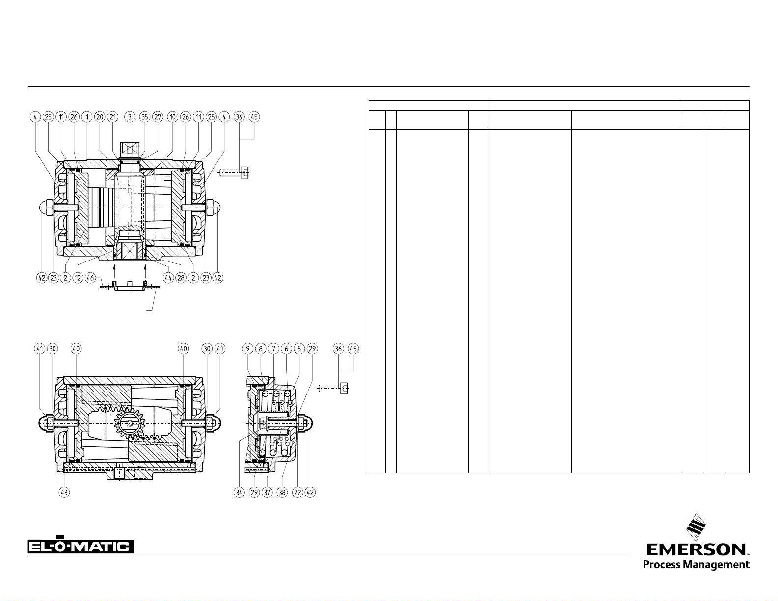
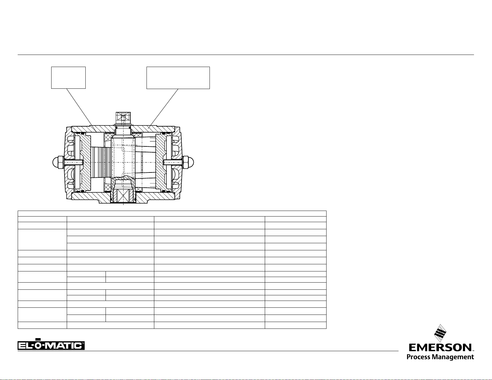
CONSTRUCTION, PARTS AND MATERIALS P-SERIE ACTUATORS P
Parts Materials Excecutions
Nr. Description Qty. Description Specification Std
1 Body 1 Aluminum Alloy UNS A13600, ASTM B85 - - 6
2 Piston 2 Aluminum Alloy UNS A03560, ASTM B26 - - 3 Endcap PDA 2 Aluminum Alloy UNS A13600, ASTM B85 - - 6
4 Endcap PSA 2 Aluminum Alloy UNS A13600, ASTM B85 - - 6
5 Drive pinion 1 Aluminum Alloy UNS 1 77075, ASTM 7075 T6 1 4 4
6 Gear Rack 2 Steel UNS G10950, ASTM A108 - - 8 Spring 14 Carbon Spring Steel UNS G10860, ASTM A228 2 2 2
9 * Bearing Bush 1 Nylatron GS PA6.6 + MoS2 - - 10 * Bearing Bush 1 Delrin POM - - 14 * Guide band 2 PTFE, Carbon filled PTFE + 25% C - - 15 * Guide band 2 PTFE, Carbon filled PTFE + 25% C - - 16 * O-ring 2 Nitrile Rubber Buna N - - 17 * O-ring 2 Nitrile Rubber Buna N - - 18 * O-ring 1 Nitrile Rubber Buna N - - 19 * O-ring 1 Nitrile Rubber Buna N - - 20 * Spring Clip 1 Carbon Spring Steel MIL - R-212 48B 2 5 5
21 * Thrust Washer 1 ZEDEX 100 K - - - 23 Bolt 4 Alloy Steel 12.9 ASTM F568 - - 24 Endcap bolt PDA 20 Alloy Steel 8.8 ASTM F568 2 4 4
25 Endcap bolt PSA 20 Alloy Steel 8.8 ASTM F568 2 4 4
26 * O-ring 2 Nitrile Rubber Buna N - - 27 Threaded insert 20 Steel UNS G10430, ASTM A29 3 3 3
* Recommended spare parts (contained in Repair kit)
S.S.
Shaft
Notes
1 Hard anodized
2 Deltatone® Coating
3 Zinc plated and passivated
4 Stainless Steel AISI 304
5 Stainless Steel, X35CrM017
6 CSR Coating (see A4.204.02)
7 P4000 has a stainless steel (AISI 304)
locking ring between spring clip (20)
and thrust washer (21)
8 P4000 has in the springs a guiding bush (PVC)
CSR
Remark
All materials are European origin, listed are the nearest US equivalents
Finish
Standard : Polyester non-TGIC based powder coating
(see data sheet A4.204.01)
DOUBLE ACTING PD SINGLE ACTING PS
www.El-O-matic.com
Copyright © Emerson Process Management. The information in this document is subject to change without notice.
Updated data sheets can be obtained from our website www.El-O-Matic.com or from your nearest Valve Automation Center USA: +1 813 319 0266 Eur ope: +31 74 256 10 10 Asia-Pacific: +65 6501 4600
CSR : CSR Coating (see data sheet A4.204.02)
Data sheet
TM
5
6
8
10
12
13
14
12347
9
11
Sheet No.:
Date: November 2009
A1.101.60 Rev. A
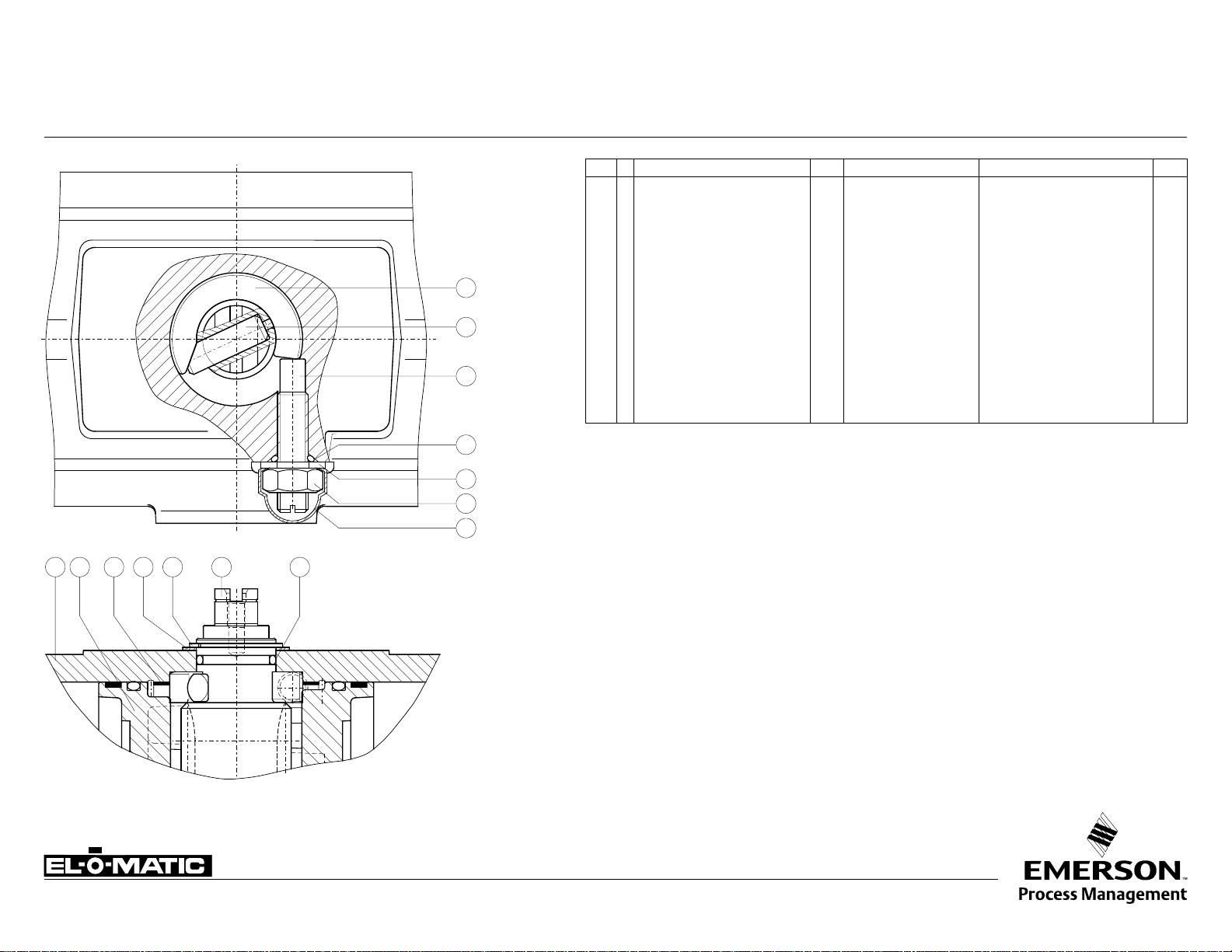
CONSTRUCTION, PARTS AND MATERIALS DSA ACTUATOR
Nr. Description Qty. Material Specification Note
1 Body DSA 1 Aluminum Alloy UNS A13600, ASTM B85 2 Piston DSA 2 Aluminum Alloy UNS A03560, ASTM B26 3 Drive pinion DSA 1 Aluminum Alloy UNS 1 77075, ASTM 7075 T6 1
4 * Guide Band DSA 1 Nylatron GS UNS A13600, ASTM B85 5 Cam for stroke adj. DSA 1 Stainless Steel UNS A13600, ASTM B85 6 Shaftpin for stroke adj. DSA 1 Chrome nickel steel UNS G10860, ASTM A228 7 * Washer 1 ZEDEX 100 K - 8 * Washer 1 Nylon UNS G10860, ASTM A228 -
9 * O-ring shaft top 1 Nitrile Rubber C45, DIN 17200 10 * O-ring limit stop bolt DSA 1 Nitrile Rubber PA6.6 + MoS2 11 Circlip 1 Carbon spring steel PTFE + 25% C 2
12 Limitstop bolt DSA 1 Stainless Steel PA6.6 + MoS2 13 Nut 1 Stainless Steel POM 14 Nut Cover 1 Polyethylene Buna N -
* Recommended spare parts (contained in Repair kits DSA)
Finish
Polyester non-TGIC based powder coating (see data sheet A4.204.01)
Note
1 Hard anodized
2 Deltatone® coating
DSA
Remark
This data sheet shows only the extra or specific parts of a DSA actuator.
For all the other parts see data sheet A1.101.33
www.El-O-matic.com
Copyright © Emerson Process Management. The information in this document is subject to change without notice.
Updated data sheets can be obtained from our website www.El-O-Matic.com or from your nearest Valve Automation Center USA: +1 813 319 0266 Eur ope: +31 74 256 10 10 Asia-Pacific: +65 6501 4600
Data sheet
Sheet No.:
Date: June 2010
A1.101.70 Rev. C
LOW TEMPERATURE ACTUATOR SPECIFICATIONS
-40°C / +80°C
-40°F / +176°F
Silicone
MVQ 70
Sealings
Materials
Part Material Specifications Remark
Housing
Drive Shaft
Piston
Sealings
Grease
Shaft bearings
Piston bearings
Bodybearings
Shaft thrust washer
End cap bolts
Springs
Castrol Optitemp TT1
Low Temperature
A double piston, rack and pinion pneumatic actuator incorporating a three point piston support
system, anti-blowout spindle and with high duty synthetic bearings at all bearing points.
Grease
This version is a standard aluminum actuator, but incorporating parts and materials suitable for
low temperature operation.
Note
When operating actuators in sub-zero temperatures (< 0°C or < 32°F) care should be taken to
counter the effects of freezing condensate inside the actuator.
Specification
Max. pressure : 120 psi (8 bar)
Torque : Standard
Media : Air or non corrosive gas
Temperature : -40°F to +176°F (-40°C to +80°C)
Finish : Polyester non-TGIC based powder coating (see data sheet A4.204.01)
Spare parts
Dedicated low temperature spare parts are available for maintenance or make a standard
actuator suiteable for low temperature operation.
Aluminum Alloy UNS A13600, ASTM B85
Aluminum Alloy UNS 1 77075, ASTM 7075 T6 Hard anodized
Steel (180° rotation) ETG100 or 42CrMo4V XM Zinc Plated type > P750
Stainless Steel Sandvic 1802, SS2382 or X35CrM017 type > E950
Aluminum Alloy UNS A03560, ASTM B26
Silicone MVQ 70 O-rings -/-
Description
Castrol Optitemp TT1
Top : Delrin POM
Bottom : Nylatron PA6.6 + MoS2
PTFE 25% Carbon filled
PTFE (“P” serie) 25% Carbon filled
Nylatron (“E” serie) PA6.6 + MoS2
ZEDEX 100 K -/-
Stainless Steel (“E” serie) AISI 304 A2
Alloy Steel (“P” serie) 8.8 DIN 912
Carbon Spring Steel UNS G10860, ASTM A228
-/-
Deltatone
Deltatone
®
coating
®
coating
www.El-O-matic.com
Copyright © Emerson Process Management. The information in this document is subject to change without notice.
Updated data sheets can be obtained from our website www.El-O-Matic.com or from your nearest Valve Automation Center USA: +1 813 319 0266 Europe: +31 74 256 10 10 Asia-Pacific: +65 6501 4600

Data sheet
Sheet No.:
Date: January 2010
A1.101.71 Rev. B
HIGH TEMPERATURE ACTUATOR SPECIFICATIONS
-20°C / +120°C
-4°F / +248°F
Sealings
Materials
Part Material Specifications Remark
Housing
Drive Shaft
Piston
Sealings
Grease
Shaft bearings
Piston bearings
Bodybearings
Shaft thrust washer
End cap bolts
Springs
Viton
FPM
Castrol
LMX
A double piston, rack and pinion pneumatic actuator incorporating a three point piston support
system, anti-blowout spindle and with high duty synthetic bearings at all bearing points.
Grease
This version is a standard aluminum actuator, but incorporating parts and materials suitable for
high temperature operation.
Specification
Max. pressure : 8 bar ~ 120psi
Torque : Standard
Media : Air or non corrosive gas
Temperature : -4°F to +248°F (-20°C to +120°C)
Finish : Polyester non-TGIC based powder coating (see data sheet A4.204.01)
Spare parts
Dedicated high temperature spare parts are available for maintenance or make a standard
actuator suiteable for high temperature operation.
Aluminum Alloy UNS A13600, ASTM B85
Aluminum Alloy UNS 1 77075, ASTM 7075 T6 Hard anodized
Steel (180° rotation) ETG100 or 42CrMo4V XM Zinc Plated type > P750
Stainless Steel Sandvic 1802, SS2382 or X35CrM017 type > E950
Aluminum Alloy UNS A03560, ASTM B26
Viton FPM O-rings -/Castrol LMX -/-
Top : Delrin POM
Bottom : Nylatron PA6.6 + MoS2
PTFE 25% Carbon filled
PTFE (“P” serie) 25% Carbon filled
Nylatron (“E” serie) PA6.6 + MoS2
ZEDEX 100 K -/-
Description
Stainless Steel (“E” serie) AISI 304 A2
Alloy Steel (“P” serie) 8.8 DIN 912 Deltatone
Carbon Spring Steel UNS G10860, ASTM A228 Deltatone
®
coating
®
coating
www.El-O-matic.com
Copyright © Emerson Process Management. The information in this document is subject to change without notice.
Updated data sheets can be obtained from our website www.El-O-Matic.com or from your nearest Valve Automation Center USA: +1 813 319 0266 Eur ope: +31 74 256 10 10 Asia-Pacific: +65 6501 4600
Data sheet
TM
Sheet No.:
Date: November 2009
A4.201 Rev.A
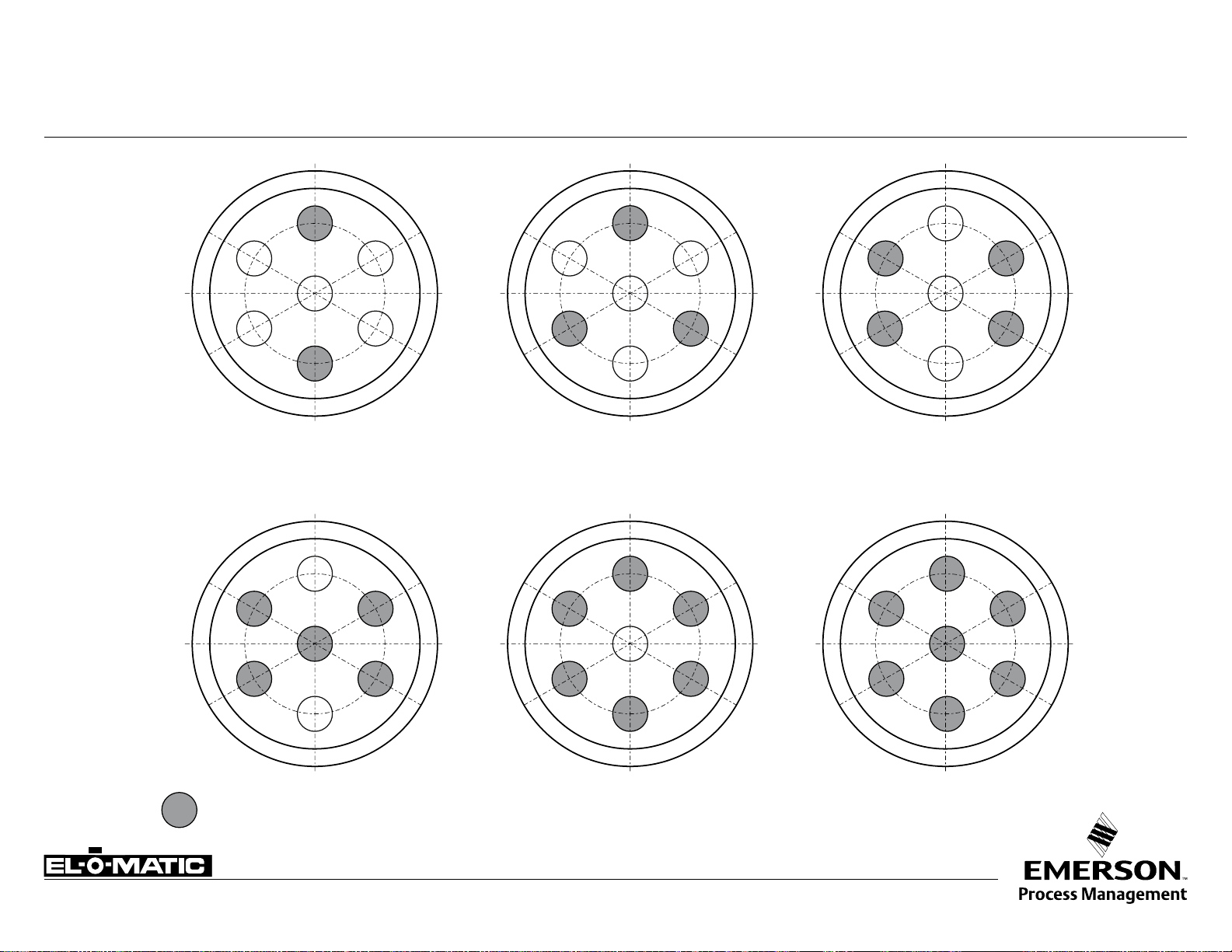
INSTALLATION OF SPRINGS OF P-SERIES ACTUATOR P
4 SPRINGS 6 SPRINGS 8 SPRINGS
10 SPRINGS 12 SPRINGS 14 SPRINGS
SPRING
www.El-O-matic.com
Copyright © Emerson Process Management. The information in this document is subject to change without notice.
Updated data sheets can be obtained from our website www.El-O-Matic.com or from your nearest Valve Automation Center USA: +1 813 319 0266 Eur ope: +31 74 256 10 10 Asia-Pacific: +65 6501 4600
Data sheet
TM
Sheet No.:
Date: November 2009
A4.202 Rev.A
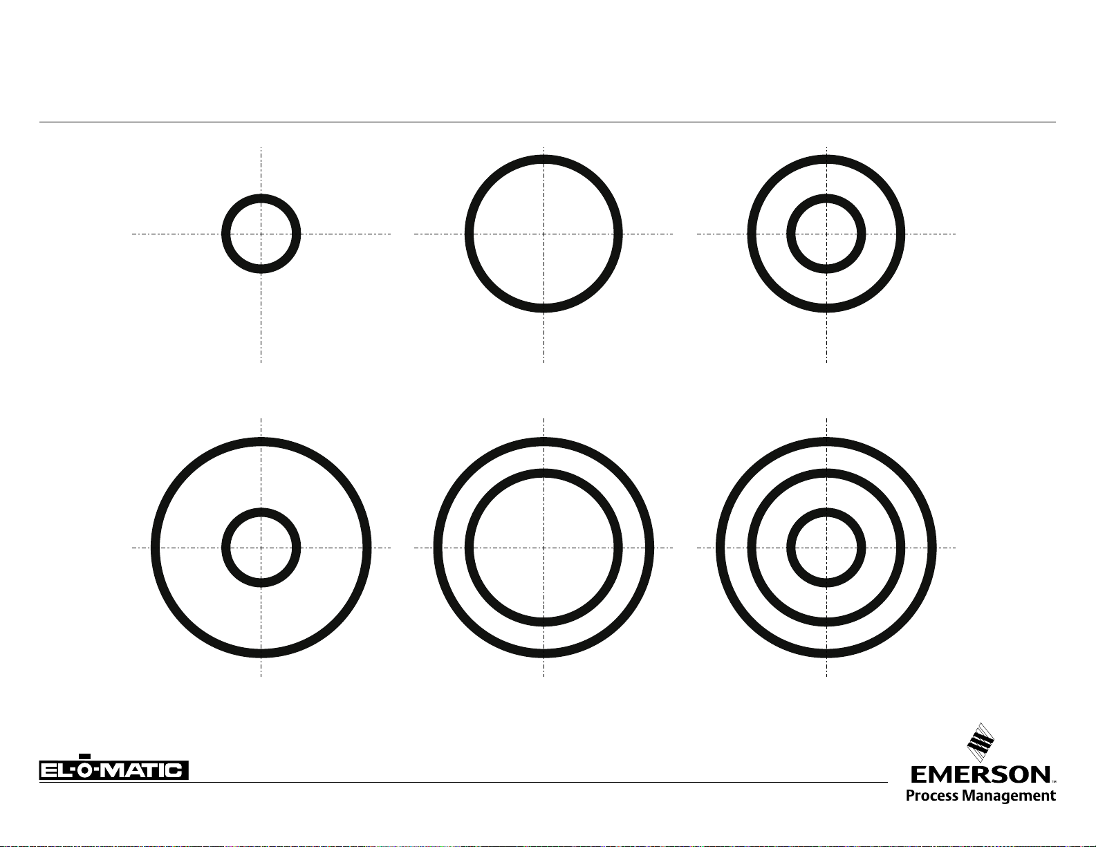
INSTALLATION OF SPRINGS OF E-SERIES ACTUATOR E
SPRING SET No. 1
inner spring
SPRING SET No. 4
inner spring
outer spring
SPRING SET No. 2
mid spring
SPRING SET No. 5
mid spring
outer spring
SPRING SET No. 3
inner spring
mid spring
SPRING SET No. 6
inner spring
mid spring
outer spring
www.El-O-matic.com
Copyright © Emerson Process Management. The information in this document is subject to change without notice.
Updated data sheets can be obtained from our website www.El-O-Matic.com or from your nearest Valve Automation Center USA: +1 813 319 0266 Eur ope: +31 74 256 10 10 Asia-Pacific: +65 6501 4600
 Loading...