


OXYMITTER 4000 IM-106-340
Table of contents
 Loading...
Instruction Manual
IM-106-340, Rev 4.0
May 2006
Oxymitter 4000
Oxygen Transmitter
http://www.raihome.com


HIGHLIGHTS OF CHANGES
Effective May 31, 2006 Rev. 4.0
Page Summary
General Reformatted entire manual from a two column layout. Removed all references to JIS
specifications. Replaced SPS 4000 information with SPS 4001B information.
Cover Updated photo, revision number and date.
viii Removed Figure 3. Oxymitter 4000 with SPS 4000 Wiring Diagram from Quick Start
Guide.
1-2 Revised Figure 1-1 to show SPS 4001B and updated IMPS 4000.
1-5 Revised Figure 1-2 to show SPS 4001B.
1-8 Added step 11 and Figure 1-6.
1-10, 1-11 Revised Figure 1-8 and Figure 1-9 to show SPS 4001B.
1-12 Removed Components paragraph.
1-13 Removed Figure 1-9. SPS 4000.
1-15 Updated Figure 1-14. Abrasive Shield Assembly.
1-16, 1-17 Revised Specifications.
1-18, 1-19 Revised Product Matrix table.
2-1 Added two additional warnings.
2-5 Removed Figure 2-3. Oxymitter 4000 Installation (with SPS 4000).
2-12, 2-15 Revised Figure 2-9 and Figure 2-10 to show grounding locations.
2-16 Revised Install Interconnecting Cable paragraph. Removed Electrical Installation (For
Oxymitter 4000 with SPS 400).
2-18 Added SPS 4001B Connections.
3-1, 4-1 Revised Terminal Block Wiring text.
5-2 Added Reference Air information.
7-9 Added D/A Trim Procedure.
8-3 Revised Alarm Indications to include signal alarm levels.
8-23 Removed SPS 4000 Troubleshooting.
9-8, 9-9 Revised Figure 9-3 and Figure 9-4.
9-11, 9-13 Revised Figure 9-6 and Figure 9-7 with updated circuit board.
9-17 Revised Figure 9-10.
9-20 Removed SPS 4000 Maintenance and Component Replacement.
10-3, 10-4 Updated part numbers for the Cell Replacement Kit, ANSI 15’ and 18’.
10-4 Updated part numbers for the Contact and Thermocouple Replacement Assembly, 15’ and
18’.

HIGHLIGHTS OF CHANGES (CONTINUED)
Effective May 31, 2006 Rev. 4.0 (Continued)
Page Summary
10-5 Removed Ceramic Diffuser Hub Assy. Changed part numbers 4851B89G04 and
4851B90G04 to 10 microns.
10-6 Revised Table 10-2. Removed Replacement Parts for SPS 4000 table.
11- 4 Revised Figure 11-4 to show the SPS 4001B.
11- 6 Added Figure 11-7 and explanation of the Oxybalance Display and Averaging System.
A-21 Added General Precautions for Handling and Storing High Pressure Gas Cylinders.

Instruction Manual
IM-106-340, Rev 4.0
May 2006
Oxymitter 4000
Table of Contents
Essential Instructions . . . . . . . . . . . . . . . . . . . . . . . . . . . . . . . . . . . . . . . . i
SECTION i
Introduction
SECTION 1
Description and
Specifications
Preface. . . . . . . . . . . . . . . . . . . . . . . . . . . . . . . . . . . . . . . . . . . . . . . . . . iv
Definitions . . . . . . . . . . . . . . . . . . . . . . . . . . . . . . . . . . . . . . . . . . . . . . . iv
Symbols . . . . . . . . . . . . . . . . . . . . . . . . . . . . . . . . . . . . . . . . . . . . . . . . . iv
What You Need To Know. . . . . . . . . . . . . . . . . . . . . . . . . . . . . . . . . . . . v
Can You Use the Quick Start Guide? . . . . . . . . . . . . . . . . . . . . . . . . . .vii
Quick Start Guide for Oxymitter 4000 Systems . . . . . . . . . . . . . . . . . . viii
Quick Reference Guide Manual Calibration Instructions . . . . . . . . . . . . ix
HART Communicator Fast Key Sequences . . . . . . . . . . . . . . . . . . . . . . x
Component Checklist . . . . . . . . . . . . . . . . . . . . . . . . . . . . . . . . . . . . . . 1-1
System Overview . . . . . . . . . . . . . . . . . . . . . . . . . . . . . . . . . . . . . . . . . 1-1
Scope . . . . . . . . . . . . . . . . . . . . . . . . . . . . . . . . . . . . . . . . . . . . . . . 1-1
System Description . . . . . . . . . . . . . . . . . . . . . . . . . . . . . . . . . . . . . 1-3
System Configuration . . . . . . . . . . . . . . . . . . . . . . . . . . . . . . . . . . . 1-4
System Features. . . . . . . . . . . . . . . . . . . . . . . . . . . . . . . . . . . . . . . 1-4
Handling the Oxymitter 4000 . . . . . . . . . . . . . . . . . . . . . . . . . . . . . 1-8
System Considerations . . . . . . . . . . . . . . . . . . . . . . . . . . . . . . . . . .1-9
IMPS 4000 (Optional). . . . . . . . . . . . . . . . . . . . . . . . . . . . . . . . . . . . . 1-12
SPS 4001B (Optional) . . . . . . . . . . . . . . . . . . . . . . . . . . . . . . . . . . . . 1-12
Mounting . . . . . . . . . . . . . . . . . . . . . . . . . . . . . . . . . . . . . . . . . . . . 1-12
Operation . . . . . . . . . . . . . . . . . . . . . . . . . . . . . . . . . . . . . . . . . . . 1-12
Model 751 Remote Powered Loop LCD Display . . . . . . . . . . . . . . . . 1-13
Probe Options . . . . . . . . . . . . . . . . . . . . . . . . . . . . . . . . . . . . . . . . . . 1-13
Diffusion Elements . . . . . . . . . . . . . . . . . . . . . . . . . . . . . . . . . . . . 1-13
Specifications . . . . . . . . . . . . . . . . . . . . . . . . . . . . . . . . . . . . . . . . . . . 1-16
SECTION 2
Installation
SECTION 3
Configuration of
Oxymitter 4000
with Membrane
Keypad
Mechanical Installation . . . . . . . . . . . . . . . . . . . . . . . . . . . . . . . . . . . . . 2-2
Selecting Location. . . . . . . . . . . . . . . . . . . . . . . . . . . . . . . . . . . . . . 2-2
Probe Installation . . . . . . . . . . . . . . . . . . . . . . . . . . . . . . . . . . . . . . 2-2
Remote Electronics Installation. . . . . . . . . . . . . . . . . . . . . . . . . . . . 2-9
Electrical Installation (with Integral Electronics) . . . . . . . . . . . . . . . . .2-10
Electrical Installation (with Remote Electronics) . . . . . . . . . . . . . . . . 2-13
Install Interconnecting Cable. . . . . . . . . . . . . . . . . . . . . . . . . . . . . 2-16
Pneumatic Installation . . . . . . . . . . . . . . . . . . . . . . . . . . . . . . . . . . . .2-16
IMPS 4000 Connections . . . . . . . . . . . . . . . . . . . . . . . . . . . . . . . . . . 2-18
SPS 4001B Connections . . . . . . . . . . . . . . . . . . . . . . . . . . . . . . . . . . 2-18
Verify Installation . . . . . . . . . . . . . . . . . . . . . . . . . . . . . . . . . . . . . . . . . 3-1
Mechanical Installation . . . . . . . . . . . . . . . . . . . . . . . . . . . . . . . . . . 3-1
Terminal Block Wiring . . . . . . . . . . . . . . . . . . . . . . . . . . . . . . . . . . .3-1
Oxymitter 4000 Configuration . . . . . . . . . . . . . . . . . . . . . . . . . . . . . 3-2
Logic I/O. . . . . . . . . . . . . . . . . . . . . . . . . . . . . . . . . . . . . . . . . . . . . . . . 3-5
Recommended Configuration . . . . . . . . . . . . . . . . . . . . . . . . . . . . . 3-6
TOC-1

Oxymitter 4000
Instruction Manual
IM-106-340, Rev 4.0
May 2006
SECTION 4
Configuration of
Oxymitter 4000 with LOI
SECTION 5
Startup and Operation of
Oxymitter 4000 with
Membrane Keypad
SECTION 6
Startup and Operation of
Oxymitter 4000 with LOI
Verify installation . . . . . . . . . . . . . . . . . . . . . . . . . . . . . . . . . . . . . . . . . 4-1
Mechanical Installation . . . . . . . . . . . . . . . . . . . . . . . . . . . . . . . . . . 4-1
Terminal Block Wiring. . . . . . . . . . . . . . . . . . . . . . . . . . . . . . . . . . . 4-1
Oxymitter 4000 Configuration. . . . . . . . . . . . . . . . . . . . . . . . . . . . . 4-2
Logic I/O . . . . . . . . . . . . . . . . . . . . . . . . . . . . . . . . . . . . . . . . . . . . . . . 4-4
Recommended Configuration. . . . . . . . . . . . . . . . . . . . . . . . . . . . . 4-6
Power Up . . . . . . . . . . . . . . . . . . . . . . . . . . . . . . . . . . . . . . . . . . . . . . . 5-1
Operation . . . . . . . . . . . . . . . . . . . . . . . . . . . . . . . . . . . . . . . . . . . . . . . 5-2
Overview. . . . . . . . . . . . . . . . . . . . . . . . . . . . . . . . . . . . . . . . . . . . . 5-2
Power Up . . . . . . . . . . . . . . . . . . . . . . . . . . . . . . . . . . . . . . . . . . . . . . . 6-1
Start Up Oxymitter 4000 Calibration . . . . . . . . . . . . . . . . . . . . . . . . . . 6-3
Navigating the Local Operator Interface . . . . . . . . . . . . . . . . . . . . . . . 6-3
Overview. . . . . . . . . . . . . . . . . . . . . . . . . . . . . . . . . . . . . . . . . . . . . 6-3
Lockout . . . . . . . . . . . . . . . . . . . . . . . . . . . . . . . . . . . . . . . . . . . . . . 6-3
LOI Key Designations . . . . . . . . . . . . . . . . . . . . . . . . . . . . . . . . . . . . . 6-4
LOI Menu Tree. . . . . . . . . . . . . . . . . . . . . . . . . . . . . . . . . . . . . . . . . . . 6-4
Oxymitter 4000 Setup at the LOI . . . . . . . . . . . . . . . . . . . . . . . . . . . . . 6-6
LOI Installation. . . . . . . . . . . . . . . . . . . . . . . . . . . . . . . . . . . . . . . . . . . 6-9
Oxymitter 4000 Test Points . . . . . . . . . . . . . . . . . . . . . . . . . . . . . . . . 6-10
Remote Powered Loop LCD Display (Optional) . . . . . . . . . . . . . . . . 6-10
SECTION 7
HART/AMS
SECTION 8
Troubleshooting
SECTION 9
Maintenance and Service
Overview . . . . . . . . . . . . . . . . . . . . . . . . . . . . . . . . . . . . . . . . . . . . . . . 7-1
HART Communicator Signal Line Connections. . . . . . . . . . . . . . . . . . 7-2
HART Communicator PC Connections . . . . . . . . . . . . . . . . . . . . . . . . 7-2
Off-Line and On-Line Operations. . . . . . . . . . . . . . . . . . . . . . . . . . . . . 7-4
Logic I/O Configurations . . . . . . . . . . . . . . . . . . . . . . . . . . . . . . . . . . . 7-4
HART/AMS Menu Tree . . . . . . . . . . . . . . . . . . . . . . . . . . . . . . . . . . . . 7-4
HART Communicator O
Defining a Timed Calibration via HART . . . . . . . . . . . . . . . . . . . . . . . . 7-9
D/A Trim Procedure . . . . . . . . . . . . . . . . . . . . . . . . . . . . . . . . . . . . . . . 7-9
Overview . . . . . . . . . . . . . . . . . . . . . . . . . . . . . . . . . . . . . . . . . . . . . . . 8-1
General . . . . . . . . . . . . . . . . . . . . . . . . . . . . . . . . . . . . . . . . . . . . . . . . 8-3
Alarm Indications . . . . . . . . . . . . . . . . . . . . . . . . . . . . . . . . . . . . . . . . . 8-3
Alarm Contacts . . . . . . . . . . . . . . . . . . . . . . . . . . . . . . . . . . . . . . . . . . 8-4
Identifying and Correcting Alarm Indications . . . . . . . . . . . . . . . . . . . . 8-5
Calibration Passes, but Still Reads Incorrectly . . . . . . . . . . . . . . . . . 8-22
Overview . . . . . . . . . . . . . . . . . . . . . . . . . . . . . . . . . . . . . . . . . . . . . . . 9-1
Calibration with Keypad . . . . . . . . . . . . . . . . . . . . . . . . . . . . . . . . . . . . 9-1
Automatic Calibration . . . . . . . . . . . . . . . . . . . . . . . . . . . . . . . . . . . 9-2
Semi-Automatic Calibration . . . . . . . . . . . . . . . . . . . . . . . . . . . . . . 9-3
Manual Calibration with Membrane Keypad. . . . . . . . . . . . . . . . . . 9-3
Calibration with LOI . . . . . . . . . . . . . . . . . . . . . . . . . . . . . . . . . . . . . . . 9-5
Oxymitter 4000 Repair. . . . . . . . . . . . . . . . . . . . . . . . . . . . . . . . . . . . . 9-7
Removal and Replacement of Probe . . . . . . . . . . . . . . . . . . . . . . . 9-7
Cal Method . . . . . . . . . . . . . . . . . . . . . . . . . 7-8
2
TOC-2

Instruction Manual
IM-106-340, Rev 4.0
May 2006
Oxymitter 4000
SECTION 10
Replacement Parts
SECTION 11
Optional
Accessories
APPENDIX A
Safety Data
APPENDIX B
Return of Material
Probe Replacement Parts . . . . . . . . . . . . . . . . . . . . . . . . . . . . . . . . .10-1
Electronics Replacement Parts . . . . . . . . . . . . . . . . . . . . . . . . . . . . .10-6
HART Handheld 375 Communicator . . . . . . . . . . . . . . . . . . . . . . . . .11-1
Asset Management Solutions (AMS) . . . . . . . . . . . . . . . . . . . . . . . . . 11-2
By-Pass Packages . . . . . . . . . . . . . . . . . . . . . . . . . . . . . . . . . . . . . . . 11-2
IMPS 4000 Intelligent Multiprobe Test Gas Sequencer . . . . . . . . . . .11-3
SPS 4001B Single Probe Autocalibration Sequencer . . . . . . . . . . . . 11-4
O
Calibration Gas . . . . . . . . . . . . . . . . . . . . . . . . . . . . . . . . . . . . . . . 11-5
2
Catalyst Regeneration . . . . . . . . . . . . . . . . . . . . . . . . . . . . . . . . . . . . 11-6
OxyBalance Display and Averaging System . . . . . . . . . . . . . . . . . . . 11-6
Safety Instructions . . . . . . . . . . . . . . . . . . . . . . . . . . . . . . . . . . . . . . . A-2
Safety Data Sheet for Ceramic Fiber Products . . . . . . . . . . . . . . . . A-15
Returning Material . . . . . . . . . . . . . . . . . . . . . . . . . . . . . . . . . . . . . . . B-1
TOC-3

Oxymitter 4000
Instruction Manual
IM-106-340, Rev 4.0
May 2006
TOC-4

Instruction Manual
IM-106-340, Rev. 4.0
May 2006
Oxymitter 4000
Oxymitter Oxygen Transmitters
READ THIS PAGE BEFORE PROCEEDING!
ESSENTIAL INSTRUCTIONS
Emerson Process Management designs, manufactures and tests its products
to meet many national and international standards. Because these
instruments are sophisticated technical products, you MUST properly
install, use, and maintain them to ensure they continue to operate within
their normal specifications. The following instructions MUST be adhered to
and integrated into your safety program when installing, using, and
maintaining Rosemount Analytical products. Failure to follow the proper
instructions may cause any one of the following situations to occur: Loss of
life; personal injury; property damage; damage to this instrument; and
warranty invalidation.
• Read all instructions
product.
• If you do not understand any of the instructions, contact your
Rosemount Analytical representative for clarification.
• Follow all warnings, cautions, and instructions
supplied with the product.
• Inform and educate your personnel in the proper installation,
operation, and maintenance of the product.
• Install your equipment as specified in the Installation Instructions
of the appropriate Instruction Manual and per applicable local and
national codes. Connect all products to the proper electrical and
pressure sources.
• To ensure proper performance, use qualified personnel
operate, update, program, and maintain the product.
• When replacement parts are required, ensure that qualified people use
replacement parts specified by Rosemount Analytical. Unauthorized
parts and procedures can affect the product's performance, place the
safe operation of your process at risk, and VOID YOUR WARRANTY.
Look-alike substitutions may result in fire, electrical hazards, or
improper operation.
• Ensure that all equipment doors are closed and protective covers
are in place, except when maintenance is being performed by
qualified persons, to prevent electrical shock and personal injury.
prior to installing, operating, and servicing the
marked on and
to install,
http://www.processanalytic.com
The information contained in this document is subject to change without
notice.
If a Model 275/375 Universal HART® Communicator is used with this unit, the software
within the Model 275/375 may require modification. If a software modification is required,
please contact your local Rosemount Analytical Service Group or National Response
Center at 1-800-433-6076 or 1-888-433-6829.


Instruction Manual
IM-106-340, Rev. 4.0
May 2006
Section i Introduction
Preface . . . . . . . . . . . . . . . . . . . . . . . . . . . . . . . . . . . . . . . . . page iv
Definitions . . . . . . . . . . . . . . . . . . . . . . . . . . . . . . . . . . . . . . page iv
Symbols . . . . . . . . . . . . . . . . . . . . . . . . . . . . . . . . . . . . . . . . page iv
What You Need To Know . . . . . . . . . . . . . . . . . . . . . . . . . . page v
Can You Use the Quick Start Guide? . . . . . . . . . . . . . . . . page vii
Quick Start Guide for Oxymitter 4000 Systems . . . . . . . . page viii
Quick Reference Guide Manual Calibration Instructions page ix
HART Communicator Fast Key Sequences . . . . . . . . . . . page x
Oxymitter 4000
http://www.processanalytic.com
Instruction Manual
IM-106-340, Rev. 4.0
Oxymitter 4000
May 2006
PREFACE The purpose of this manual is to provide information concerning the
components, functions, installation and maintenance of the Oxymitter 4000
Oxygen Transmitter.
Some sections may describe equipment not used in your configuration. The
user should become thoroughly familiar with the operation of this module
before operating it. Read this instruction manual completely.
DEFINITIONS The following definitions apply to WARNINGS, CAUTIONS, and NOTES
found throughout this publication.
Highlights an operation or maintenance procedure, practice, condition, statement, etc. If not
strictly observed, could result in injury, death, or long-term health hazards of personnel.
Highlights an operation or maintenance procedure, practice, condition, statement, etc. If not
strictly observed, could result in damage to or destruction of equipment, or loss of
effectiveness.
SYMBOLS
NOTE
Highlights an essential operating procedure, condition, or statement.
:
EARTH (GROUND) TERMINAL
:
PROTECTIVE CONDUCT OR TERMINAL
:
RISK OF ELECTRICAL SHOCK
:
WARNING: REFER TO INSTRUCTION MANUAL
NOTE TO USERS
The number in the lower right corner of each illustration in this publication is a
manual illustration number. It is not a part number, and is not related to the
illustration in any technical manner.
iv
Instruction Manual
IM-106-340, Rev. 4.0
May 2006
WHAT YOU NEED TO KNOW
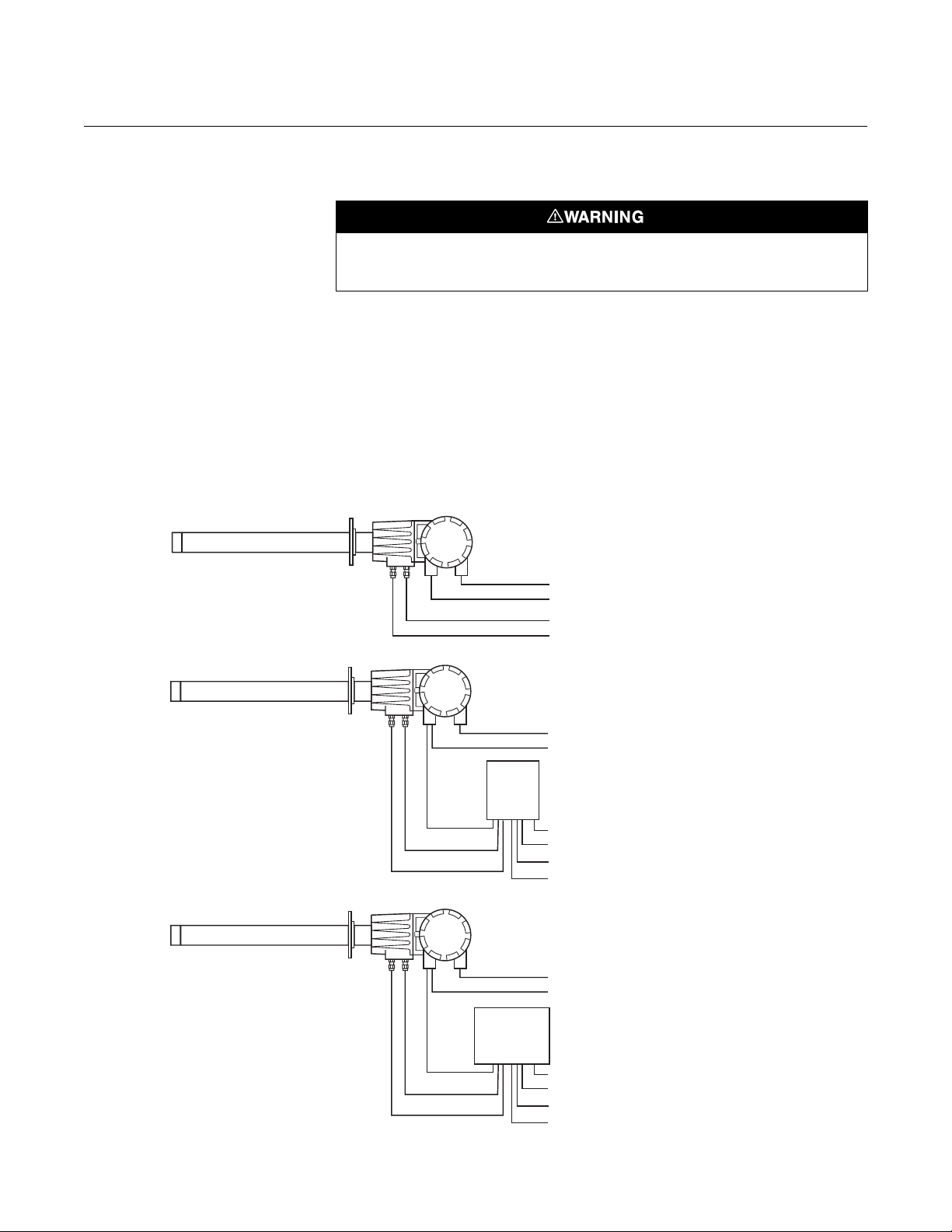
Figure 1. Installation Options Oxymitter 4000 with Integral
Electronics
Oxymitter 4000
Highlights an operation or maintenance procedure, practice, condition, statement, etc. If not
strictly observed, could result in injury, death, or long-term health hazards of personnel.
BEFORE INSTALLING AND WIRING A ROSEMOUNT ANALYTICAL
OXYMITTER 4000 OXYGEN TRANSMITTER
1. What type of installation does your system require?
Use the following drawings, Figure 1 and Figure 2, to identify which type
of installation is required for your Oxymitter 4000 system.
LOGIC I/O
Cal. Gas
Ref. Air
OXYMITTER 4000
Line Voltage
4-20 mA
Cal. Gas
Instr. Air (Ref. Air)
OXYMITTER 4000 WITH
SPS 4001B
Line Voltage
4-20 mA
SPS
4001B
Line Voltage
Cal. Gas 1
Cal. Gas 2
Instr. Air (Ref. Air)
OXYMITTER 4000 WITH REMOTE
IMPS 4000 OPTION
Line Voltage
4-20 mA
LOGIC I/O
Cal. Gas
Ref. Air
IMPS
4000
Line Voltage
Cal. Gas 1
Cal. Gas 2
Instr. Air (Ref. Air)
37260001
v
Oxymitter 4000
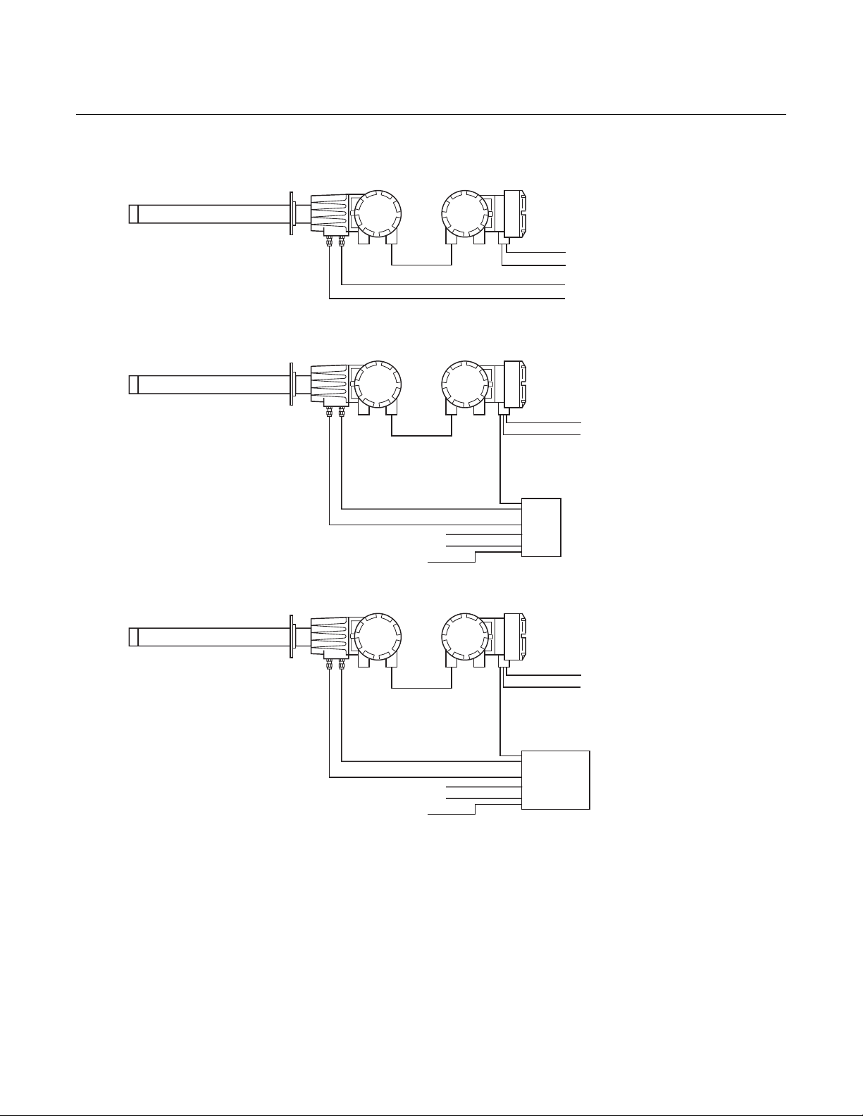
Figure 2. Installation Options Oxymitter 4000 with Remote
Electronics
Instruction Manual
IM-106-340, Rev. 4.0
May 2006
OXYMITTER 4000
Line Voltage
4-20 mA
Cal. Gas
Instr. Air (Ref. Air)
Calibration Gas
Reference Air
Cal. Gas 2
Cal. Gas 1
Instr. Air
Calibration Gas
Reference Air
Cal. Gas 2
Cal. Gas 1
Instr. Air
Logic I/O
SPS
4001B
Logic I/O
OXYMITTER 4000
WITH
REMOTE ELECTRONICS
AND SPS 4001B
Line Voltage
4-20 mA
OXYMITTER 4000
WITH
REMOTE ELECTRONICS
AND IMPS
Line Voltage
4-20 mA
IMPS
4000
37260049
vi

Instruction Manual
IM-106-340, Rev. 4.0
May 2006
Oxymitter 4000
CAN YOU USE THE QUICK START GUIDE?
Use this Quick Start Guide if...
1. Your system requires an Oxymitter 4000 with or without the SPS 4001B
OPTION. Installation options for the Oxymitter 4000 are shown in
Figure 1.
2. Your system does NOT require an IMPS 4000 OPTION installation.
3. Your system does NOT use a Remote Electronics as shown in Figure 2.
4. You are familiar with the installation requirements for the Oxymitter 4000
Oxygen Transmitter. You are familiar with the installation requirements
for the Oxymitter 4000 Oxygen Transmitter with a SPS 4001B.
If you cannot use the Quick Start Guide, turn to Section 2: Installation, in
this Instruction Manual.
vii

Oxymitter 4000
Instruction Manual
IM-106-340, Rev. 4.0
May 2006
QUICK START GUIDE FOR OXYMITTER 4000 SYSTEMS
Before using the Quick Start Guide, please read "WHAT YOU NEED TO
KNOW BEFORE INSTALLING AND WIRING A ROSEMOUNT
ANALYTICAL OXYMITTER 4000 OXYGEN TRANSMITTER" on the
preceding page.
1. Install the Oxymitter 4000 in an appropriate location on the stack or
duct. Refer to "Selecting Location" in Section 2: Installation, for
information on selecting a location for the Oxymitter 4000.
2. If using an SPS 4001B, connect the calibration gasses to the
appropriate fittings on the SPS 4001B manifold.
3. Connect reference air to the Oxymitter 4000 or SPS 4001B, as
applicable.
4. If using an SPS 4001B, make the wiring connections as shown in the
SPS 4001B Single Probe Autocalibration Sequencer Instruction
Manual.
5. If NOT using an SPS 4001B, make the following wire connections as
shown in Figure 3: line voltage, 4-20 mA, and logic I/O.
6. Verify the Oxymitter 4000 switch configuration is as desired. Refer to
"Oxymitter 4000 Configuration", "SW1 Setting", and "SW2 Setting" all in
Section 3: Configuration of Oxymitter 4000 with Membrane Keypad, or
"Oxymitter 4000 Configuration", "SW1 Setting", and "SW2 Setting" all in
Section 4: Configuration of Oxymitter 4000 with LOI.
7. Apply power to the Oxymitter 4000; the cell heater will turn on. Allow
approximately one half hour for the cell to heat to operating
temperature. Once the ramp cycle has completed and the
Oxymitter 4000 is at normal operation, proceed with step 8 or 9.
8. If using an SPS 4001B, initiate a semi-automatic calibration.
9. If NOT using an SPS 4001B, perform a manual calibration. Refer to
"Calibration with Keypad" or "Calibration with LOI" both in Section 9:
Maintenance and Service, in this instruction manual.
viii
NOTE
If your system has a membrane keypad you can refer to the Quick Start Guide
on the following pages.
Instruction Manual
IM-106-340, Rev. 4.0
May 2006
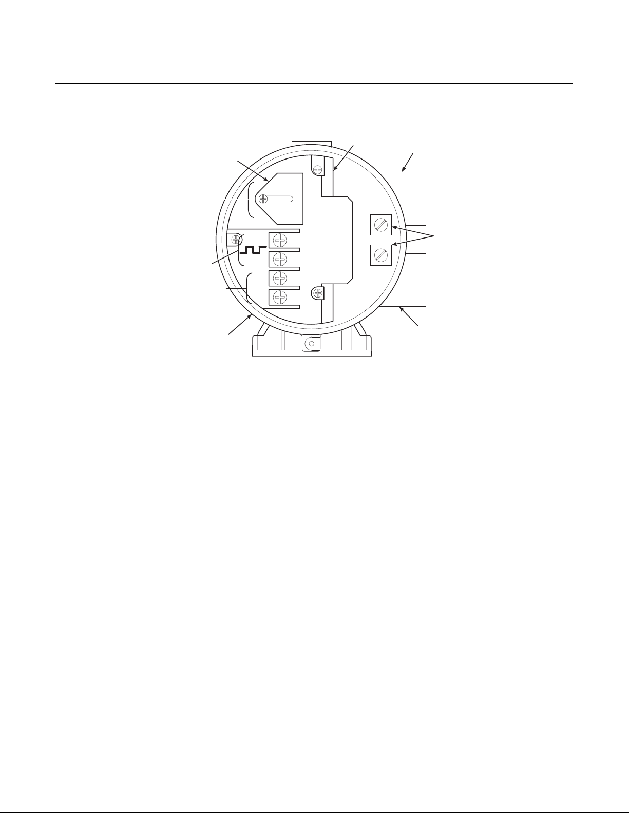
Figure 3. Oxymitter 4000 without
SPS 4001B Wiring Diagram
AC Terminal
Cover
Terminal
Block
Oxymitter 4000
AC Line
Voltage Port
(85 to 264 VAC)
QUICK REFERENCE GUIDE MANUAL CALIBRATION INSTRUCTIONS
Line Voltage
Logic I/O
4-20 mA
Signal
Left Side of
Oxymitter 4000
AC L1
AC N
Ground
Lugs
Signal
Port
29770003
4-20
+
-
+
-
Performing a Manual Calibration with a Membrane Keypad
1. Place the control loop in manual.
2. Press the CAL key. The CAL LED will light solid.
3. Apply the first calibration gas.
4. Press the CAL key. When the unit has taken the readings using the first
calibration gas, the CAL LED will flash continuously.
5. Remove the first calibration gas and apply the second calibration gas.
6. Push the CAL key. The CAL LED will light solid. When the unit has
taken the readings using the second calibration gas, the CAL LED will
flash a two-pattern flash or a three-pattern flash. A two-pattern flash
equals a valid calibration, three-pattern flash equals an invalid
calibration.
7. Remove the second calibration gas and cap off the calibration gas port.
8. Press the CAL key. The CAL LED will be lit solid as the unit purges.
When the purge is complete, the CAL LED will turn off.
9. If the calibration was valid, the DIAGNOSTIC ALARMS LEDs indicate
normal operation. If the new calibration values are not within the
parameters, the DIAGNOSTIC ALARMS LEDs will indicate an alarm.
10. Place the control loop in automatic.
ix

Oxymitter 4000
HART COMMUNICATOR FAST KEY SEQUENCES
Perform Calibration
2 3 1 1
Instruction Manual
IM-106-340, Rev. 4.0
O Upper Range Value
2
3 2 1
May 2006
Trim Analog Output
2 4
Toggle Analog Output Tracking
2 3 1 2
Analog Output Lower Range Value
2 2
3
View O Value
2
1 1 1
View Analog Output
1 2 1
Technical Support Hotline:
For assistance with technical problems, please call the Customer Support
Center (CSC). The CSC is staffed 24 hours a day, 7 days a week.
Phone: 1-800-433-6076 1-440-914-1261
In addition to the CSC, you may also contact Field Watch. Field Watch
coordinates Emerson Process Management’s field service throughout the
U.S. and abroad.
Phone: 1-800-654-RSMT (1-800-654-7768)
Rosemount Analytical may also be reached via the Internet through e-mail
and the World Wide Web:
e-mail: GAS.CSC@.emersonprocess.com
38330001
World Wide Web: www.raihome.com
x

Instruction Manual
IM-106-340, Rev. 4.0
May 2006
Oxymitter 4000
Section 1 Description and Specifications
Component Checklist . . . . . . . . . . . . . . . . . . . . . . . . . . . . . page 1-1
System Overview . . . . . . . . . . . . . . . . . . . . . . . . . . . . . . . . page 1-1
IMPS 4000 (Optional) . . . . . . . . . . . . . . . . . . . . . . . . . . . . . page 1-12
SPS 4001B (Optional) . . . . . . . . . . . . . . . . . . . . . . . . . . . . . page 1-12
Model 751 Remote Powered Loop LCD Display . . . . . . . page 1-13
Probe Options . . . . . . . . . . . . . . . . . . . . . . . . . . . . . . . . . . . page 1-13
Specifications . . . . . . . . . . . . . . . . . . . . . . . . . . . . . . . . . . . page 1-16
COMPONENT CHECKLIST
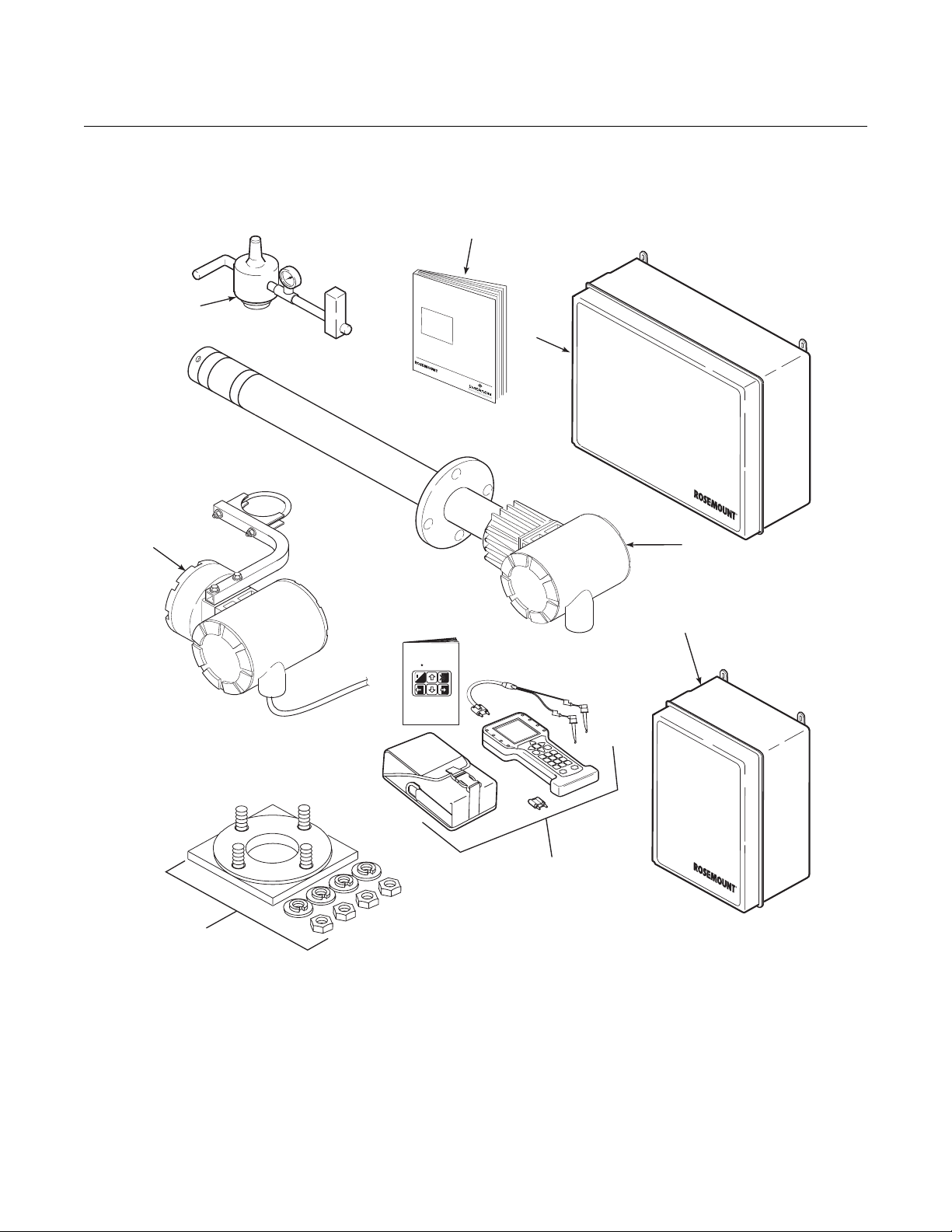
A typical Rosemount Analytical Oxymitter 4000 Oxygen Transmitter should
contain the items shown in Figure 1-1. Record the part number, serial number,
and order number for each component of your system in the table located on
the first page of this manual.
Also, use the product matrix in Table 1-1 at the end of this section to compare
your order number against your unit. The first part of the matrix defines the
model. The last part defines the various options and features of the Oxymitter
4000. Ensure the features and options specified by your order number are on
or included with the unit.
SYSTEM OVERVIEW
Scope This Instruction Manual is designed to supply details needed to install, start
up, operate, and maintain the Oxymitter 4000. Signal conditioning electronics
outputs a 4-20 mA signal representing an O
keypad or fully functional Local Operator Interface (optional) for setup,
calibration, and diagnostics. This same information, plus additional details,
can be accessed with the HART Model 275/375 handheld communicator or
Asset Management Solutions (AMS) software.
value and provides a membrane
2
http://www.processanalytic.com
Oxymitter 4000
Analytical
Figure 1-1. Typical System
Package
8
Instruction Manual
IM-106-340, Rev. 4.0
May 2006
1
I
n
s
t
r
u
c
I
t
M
i
o
-
n
1
0
M
6
-
D
a
3
n
e
4
u
c
0
e
a
C
m
l
R
b
e
e
v
r
.
2
4
0
.
0
2
5
O
X
Y
M
H
IT
A
Z
TE
A
R
O
D
R
X
O
Y
40
U
G
S
E
0
N
A
0
R
T
E
R
A
A
N
S
M
I
T
T
E
R
2
A
n
a
l
y
t
i
c
a
l
Analytical
7
MAN4275A00
English
HART
Communicator
o
5
6
1. Instruction Manual
2. IMPS 4000 Intelligent Multiprobe Test Gas Sequencer (Optional)
3. Oxymitter 4000 with Integral Electronics
4. SPS 4001B Single Probe Autocalibration Sequencer (Optional) (Shown with reference air option)
5. HART® 275/375 Communicator Package (Optional)
6. Adapter Plate with Mounting Hardware and Gasket
7. Remote Electronics and Cable (Optional)
8. Reference Air Set (used if SPS 4001B without reference air option or IMPS 4000 supplied)
3
4
Analytical
37260002
1-2

Instruction Manual
IM-106-340, Rev. 4.0
May 2006
Oxymitter 4000
System Description The Oxymitter 4000 is designed to measure the net concentration of oxygen
in an industrial combustion processes process; i.e., the oxygen remaining
after all fuels have been oxidized. The probe is permanently positioned within
an exhaust duct or stack and performs its task without the use of a sampling
system.
The equipment measures oxygen percentage by reading the voltage
developed across a heated electrochemical cell, which consists of a small
yttria stabilized, zirconia disc. Both sides of the disc are coated with porous
metal electrodes. When operated at the proper temperature, the millivolt
output voltage of the cell is given by the following Nernst equation:
EMF = KT log10(P1/P2) + C
Where:
1. P2 is the partial pressure of the oxygen in the measured gas on one
side of the cell.
2. P1 is the partial pressure of the oxygen in the reference air on the
opposite side of the cell.
3. T is the absolute temperature.
4. C is the cell constant.
5. K is an arithmetic constant.
NOTE
For best results, use clean, dry, instrument air (20.95% oxygen) as the
reference air.
When the cell is at operating temperature and there are unequal oxygen
concentrations across the cell, oxygen ions will travel from the high oxygen
partial pressure side to the low oxygen partial pressure side of the cell. The
resulting logarithmic output voltage is approximately 50 mV per decade. The
output is proportional to the inverse logarithm of the oxygen concentration.
Therefore, the output signal increases as the oxygen concentration of the
sample gas decreases. This characteristic enables the Oxymitter 4000 to
provide exceptional sensitivity at low oxygen concentrations.
The Oxymitter 4000 measures net oxygen concentration in the presence of all
the products of combustion, including water vapor. Therefore, it may be
considered an analysis on a "wet" basis. In comparison with older methods,
such as the portable apparatus, which provides an analysis on a "dry" gas
basis, the "wet" analysis will, in general, indicate a lower percentage of
oxygen. The difference will be proportional to the water content of the
sampled gas stream.
1-3

Instruction Manual
IM-106-340, Rev. 4.0
Oxymitter 4000
May 2006
System Configuration Oxymitter 4000 units are available in seven length options, giving the user the
flexibility to use an in situ penetration appropriate to the size of the stack or
duct. The options on length are 18 in. (457 mm), 3 ft (0,91 m), 6 ft (1,83 m),
9 ft (2,7 m), 12 ft (3,66 m), 15 ft (4,57 m), and 18 ft (5,49 m).
The electronics control probe temperature and provide an isolated output,
4-20 mA, that is proportional to the measured oxygen concentration. The
power supply can accept voltages of 90-250 VAC and 48/62 Hz; therefore, no
setup procedures for power are required. The oxygen sensing cell is maintained at a constant temperature by modulating the duty cycle of the probe
heater portion of the electronics. The electronics accepts millivolt signals generated by the sensing cell and produces the outputs to be used by remotely
connected user devices. The output is an isolated 4-20 mA linearized current.
The Oxymitter 4000 transmitter is available with an integral or remote electronics package. Two calibration gas sequencers are available: the IMPS
4000 and the SPS 4001B (Figure 1-2).
Systems with multiprobe applications may employ an optional IMPS 4000
Intelligent Multiprobe Test Gas Sequencer. The IMPS 4000 provides automatic calibration gas sequencing for up to four Oxymitter 4000 units and
accommodates autocalibrations based on the CALIBRATION RECOMMENDED signal from the Oxymitter 4000, a timed interval set up in HART or
the IMPS 4000, or whenever a calibration request is initiated.
For systems with one or two Oxymitter 4000 units per combustion process, an
optional SPS 4001B Single Probe Autocalibration Sequencer can be used
with each Oxymitter 4000 to provide automatic calibration gas sequencing.
The SPS 4001B is fully enclosed in a NEMA cabinet suited for wall-mounting.
The sequencer performs autocalibrations based on the CALIBRATION RECOMMENDED signal from the Oxymitter 4000, a timed interval set up in HART,
or whenever a calibration request is initiated.
System Features 1. The CALIBRATION RECOMMENDED feature detects when the sensing
cell is likely out of limits. This may eliminate the need to calibrate on a
"time since last cal" basis.
2. The cell output voltage and sensitivity increase as the oxygen
concentration decreases.
1-4
Instruction Manual
Analytical
IM-106-340, Rev. 4.0
May 2006
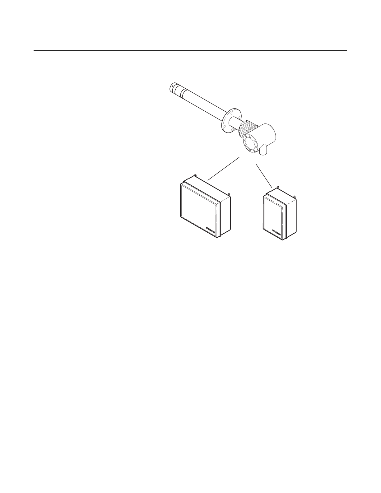
Figure 1-2. Oxymitter 4000
AutoCalibration System Options
Oxymitter 4000
OXYMITTER 4000
Analytical
IMPS 4000
(1 to 4 Probes)
Analytical
SPS 4001B
(1 Probe)
37260039
3. Membrane keypad, Figure 1-3, and HART communication are standard.
To use the HART capability, you must have either:
a. HART Model 275/375 Communicator.
b. Asset Management Solutions (AMS) software for the PC.
1-5
Oxymitter 4000
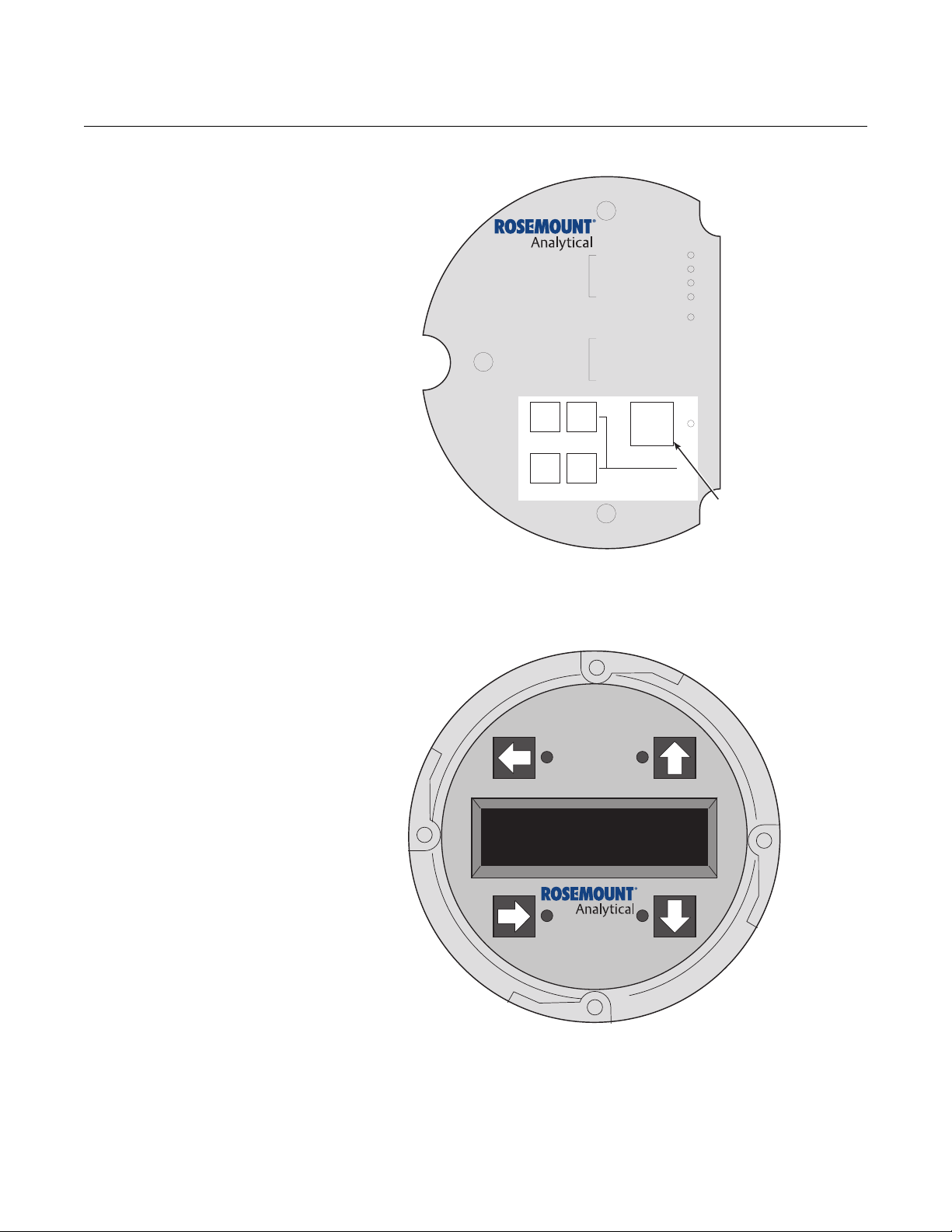
Figure 1-3. Membrane Keypad
HEATER T/C
DIAGNOSTIC
ALARMS
CALIBRATION RECOMMENDED
TEST
POINTS
HEATER
02 CELL
CALIBRATION
02 CELL mV +
02 CELL mv HEATER T/C +
HEATER T/C -
Instruction Manual
IM-106-340, Rev. 4.0
May 2006
Figure 1-4. Local Operator
Interface (LOI)
INC INC
HIGH
LOW
GAS
GAS
DEC DEC
CAL
TEST GAS +
PROCESS -
%02
MEMBRANE
KEYPAD
37260003
4. An optional Local Operator Interface, Figure 1-4, allows continuous O
display and full interface capability.
2
1-6
37260004
5. Field replaceable cell, heater, thermocouple, and diffusion element.
6. The Oxymitter 4000 is constructed of rugged 316 L stainless steel for all
wetted parts.
7. The electronics are adaptable for line voltages from 90-250 VAC;
therefore, no configuration is necessary.

Instruction Manual
IM-106-340, Rev. 4.0
May 2006
Oxymitter 4000
8. The Oxymitter 4000 membrane keypad is available in five languages:
English
French
German
Italian
Spanish
9. An operator can calibrate and diagnostically troubleshoot the Oxymitter
4000 in one of four ways:
a. Membrane Keypad. The membrane keypad, housed within the right
side of the electronics housing, provides fault indication by way of
flashing LEDs. Calibration can be performed from the membrane
keypad.
b. LOI. The optional LOI takes the place of the membrane keypad and
allows local communication with the electronics. Refer to Section 6
for more information.
c. Optional HART Interface. The Oxymitter 4000's 4-20 mA output line
transmits an analog signal proportional to the oxygen level. The
HART output is superimposed on the 4-20 mA output line. This
information can be accessed through the following:
i. Rosemount Analytical Model 275/375 Handheld
Communicator - The handheld communicator requires
Device Description (DD) software specific to the
Oxymitter 4000. The DD software will be supplied with
many Model 275/375 units but can also be programmed
into existing units at most Rosemount Analytical service
offices. See Section 7, HART/ AMS, for additional
information.
ii. Personal Computer (PC) - The use of a personal
computer requires AMS software available from
Rosemount Analytical.
iii. Selected Distributed Control Systems - The use of
distributed control systems requires input/output (I/O)
hardware and AMS software which permit HART
communications.
d. Optional IMPS 4000. The Programmable Logic Controller (PLC) in
the IMPS 4000 provides fault indications using flashing LEDs and
LCD display messages. Refer to the IMPS 4000 Intelligent
Multiprobe Test Gas Sequencer Instruction Manual for more
information.
1-7
Oxymitter 4000
+
+
++
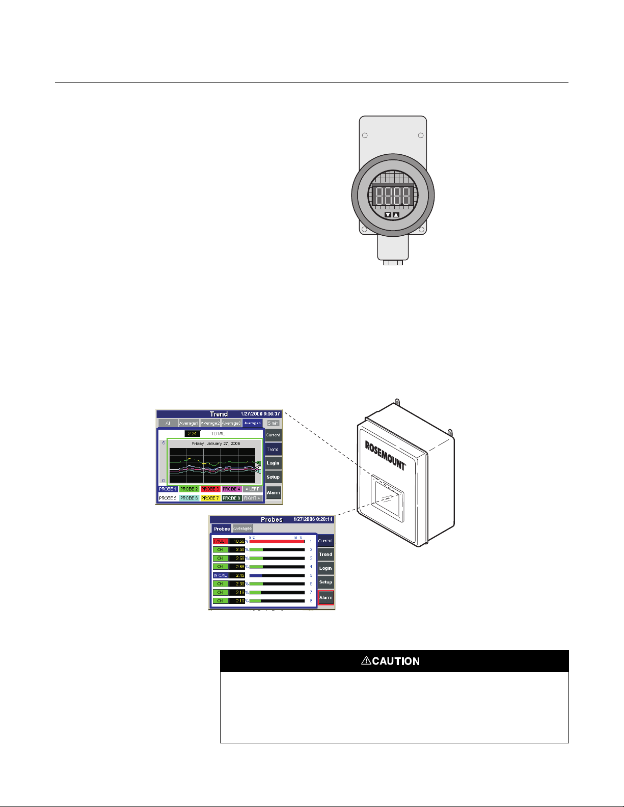
Figure 1-5. Model 751 LCD
Display Panel
Figure 1-6. OxyBalance Display
Displaying Outputs
Instruction Manual
IM-106-340, Rev. 4.0
May 2006
%
22220059
10. The optional Rosemount Analytical 751 remote-mounted LCD display
panel shown in Figure 1-5 is loop-driven by the 4-20 mA output signal
representing the O
11. Optional OxyBalance Display and Averaging System. Reviews up to
eight 4-20 mA signals from individual probes. Trends individual outputs,
calculates four programmable averages as additional 4-20 mA outputs.
percentage.
2
Handling the Oxymitter 4000
Analytical
38370013
It is important that printed circuit boards and integrated circuits are handled only when
adequate antistatic precautions have been taken to prevent possible equipment damage.
The Oxymitter 4000 is designed for industrial applications. Treat each component of the
system with care to avoid physical damage. Some probe components are made from
ceramics, which are susceptible to shock when mishandled.
1-8
Instruction Manual
IM-106-340, Rev. 4.0
May 2006
Oxymitter 4000
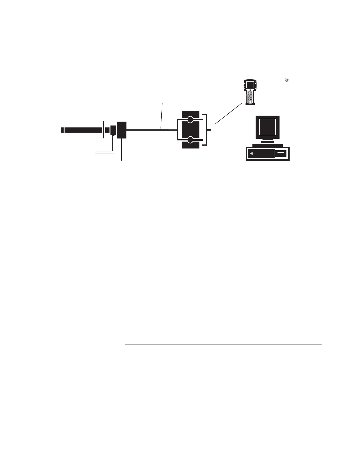
Figure 1-7. Oxymitter 4000
HART Communications and
AMS Application
HART
Model 275/375
Handheld
Interface
Hazardous Area
Oxymitter 4000
with Integral Electronics
2 Calibration Gas Lines
by Customer
[ ( ) max]300 ft 90 m
Line Voltage
4-20 mA Output
(Twisted Pairs)
Termination in
Control Room
Asset Management Solutions
System Considerations Prior to installing your Oxymitter 4000, make sure you have all the
components necessary to make the system installation. Ensure all the
components are properly integrated to make the system functional.
37260005
After verifying that you have all the components, select mounting locations
and determine how each component will be placed in terms of available line
voltage, ambient temperatures, environmental considerations, convenience,
and serviceability.
Figure 1-7 shows a typical system wiring.
A typical system installation for an Oxymitter 4000 with integral electronics is
shown in Figure 1-8. A typical system installation for an Oxymitter 4000 with
remote electronics is shown in Figure 1-9.
A source of instrument air is optional at the Oxymitter 4000 for reference
air use. Since the unit is equipped with an in place calibration feature,
provisions can be made to permanently connect calibration gas bottles to the
Oxymitter 4000.
If the calibration gas bottles will be permanently connected, a check valve is
required next to the calibration fittings on the integral electronics.
This check valve is to prevent breathing of the calibration gas line and
subsequent flue gas condensation and corrosion. The check valve is in
addition to the stop valve in the calibration gas kit or the solenoid valves in the
IMPS 4000 or SPS 4001B.
NOTE:
The electronics is rated NEMA 4X (IP66) and is capable of operation at
temperatures up to 185°F (85°C).
The optional LOI is also rated for operation at temperatures up to 185°F
(85°C). The infrared keypad functionality will degrade at temperatures above
158°F (70°C).
Retain the packaging in which the Oxymitter 4000 arrived from the factory in
case any components are to be shipped to another site. This packaging has
been designed to protect the product.
1-9
Oxymitter 4000
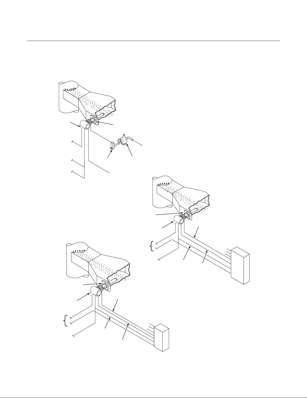
Figure 1-8. Typical System
Installation - Oxymitter 4000 with
Integral Electronics
Instruction Manual
IM-106-340, Rev. 4.0
May 2006
Gases
Stack
Oxymitter
4000
Line
Voltage
Logic I/O
4to20mA
Signal
STANDARD
Duct
Adapter
Plate
Flowmeter
Calibration
Gas
SPS 4001B* SINGLE PROBE
AUTOCALIBRATION OPTION
(WITH REFERENCE AIR OPTION)
Gases
Pressure
Regulator
Voltage
Instrument
Air Supply
(Reference Air)
Gases
Stack
Adapter
Plate
Oxymitter
4000
Line
IMPS 4000* MULTIPROBE
AUTOCALIBRATION
OPTION
Duct
Calibration
Gas
Inst. Air Supply
Calibration Gas 2
Calibration Gas 1
1-10
Adapter Plate
Line Voltage
4to20mA
Oxymitter
4000
Signal
Stack
Calibration Gas
Logic I/O
Duct
Calibration Gas 2
Calibration Gas 1
Reference
Air
4to20mA
Signal
Inst. Air Supply
SPS 4001B
Logic I/O
Reference
Air
IMPS 4000
37260047
Instruction Manual
IM-106-340, Rev. 4.0
May 2006
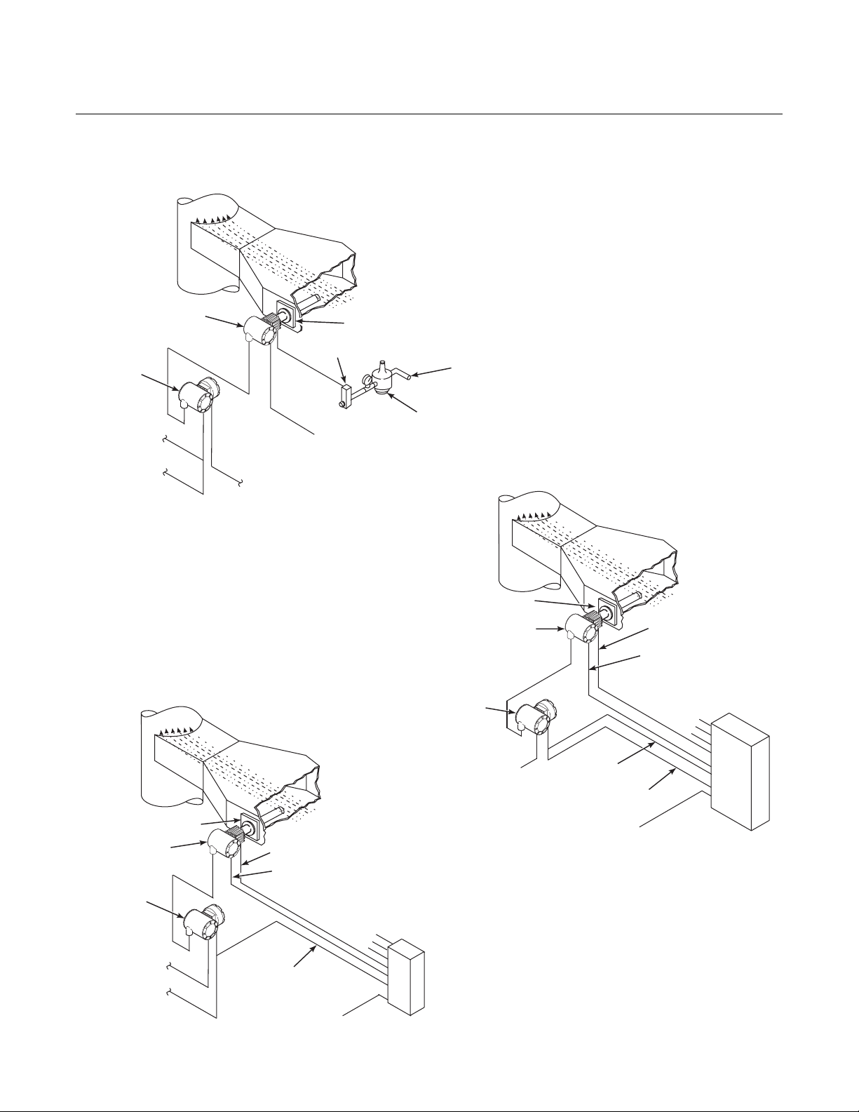
Figure 1-9. Typical System
Installation - Oxymitter 4000 with
Remote Electronics
Oxymitter 4000
Oxymitter 4000
Remote
Electronics
Logic I/O
4to20mA
Signal
Gases
Stack
Line
Voltage
STANDARD
Duct
Adapter Plate
Flowmeter
Calibration
Gas
Instrument
Air Supply
(Reference Air)
Pressure
Regulator
Adapter Plate
Gases
Stack
IMPS 4000* MULTIPROBE
AUTOCALIBRATION
OPTION
Duct
SPS 4001B* SINGLE PROBE
AUTOCALIBRATION OPTION
(WITH REFERENCE AIR OPTION)
Gases
Duct
Stack
Adapter Plate
Oxymitter
Remote
Electronics
Line Voltage
4to20mA
Signal
4000
Calibration Gas
Reference Air
Calibration Gas 1
Logic I/O
Line Voltage
Inst. Air Supply
Calibration Gas 2
Electronics
SPS 4001B
Oxymitter 4000
Remote
Line Voltage
Calibration Gas
Reference Air
Inst. Air Supply
Calibration Gas 2
Calibration Gas 1
Logic I/O
4to20mA
Signal
Line Voltage
IMPS 4000
*Note: The IMPS 4000 or SPS 4001B must
be installed in a non-hazardous,
explosive-free environment.
37260006
1-11

Instruction Manual
IM-106-340, Rev. 4.0
Oxymitter 4000
May 2006
IMPS 4000 (OPTIONAL) Information on the IMPS 4000 is available in the IMPS 4000 Intelligent
Multiprobe Test Gas Sequencer Instruction Manual.
SPS 4001B (OPTIONAL) The SPS 4001B Single Probe Autocalibration Sequencer provides the
capability of performing automatic, timed or on demand, calibrations of a
single Oxymitter 4000 without sending a technician to the installation site.
Mounting The SPS 4001B is fully enclosed in a NEMA cabinet suited for wall-mounting.
This cabinet provides added protection against dust and minor impacts. The
SPS 4001B consists of a manifold and a calibration gas flowmeter. The manifold provides electrical feedthroughs and calibration gas ports to route power
and signal connections and calibration gases to and from the sequencer. In
addition, the manifold houses two calibration gas solenoids that sequence the
gases to the Oxymitter 4000, a pressure switch that detects low calibration
gas pressure, and two PC boards. A terminal strip housed within the terminal
cover provides convenient access for all user connections.
Components optional to the SPS 4001B include a reference air flowmeter and
pressure regulator. The reference air flowmeter indicates the flow rate of
reference air continuously flowing to the Oxymitter 4000. The reference air
pressure regulator ensures the instrument air (reference air) flowing to the
Oxymitter 4000 is at a constant pressure [20 psi (138 kPa)]. The regulator
also has a filter to remove particulates in the reference air and a drain valve to
bleed the moisture that collects in the filter bowl.
Brass fittings and Teflon tubing are standard. Stainless steel fittings and
tubing are optional. Also, disposable calibration gas bottles are available as
an option or can be purchased through a local supplier.
Operation The SPS 4001B works in conjunction with the Oxymitter 4000's CALIBRA-
TION RECOMMENDED feature to perform an autocalibration. This feature
automatically performs a gasless calibration check every hour on the Oxymitter 4000. If a calibration is recommended and its contact output signal is set
for "handshaking" with the sequencer, the Oxymitter 4000 sends a signal to
the sequencer. The sequencer automatically performs a calibration upon
receiving the signal. Thus, no human interface is required for the automatic
calibration to take place. For further SPS 4001B information, refer to the SPS
4001B Single Probe Autocalibration Sequencer Instruction Manual.
1-12
Loading...