

Page 1
Liebert® DS™ Thermal Management Unit
System Design Manual - 28-105kW (8-30 Tons), Downflow/Upflow, 60Hz
Floor Mounted, Air-Cooled, Water/Glycol-Cooled, GLYCOOL Economizer Coil, Dual-Cool DX with
Secondary Chilled Water Coil
Page 2

Page 3

TABLE OF CONTENTS
LIEBERT DS MODEL NUMBER . . . . . . . . . . . . . . . . . . . . . . . . . . . . . . . . . . . . . . . . . . . . . . . . . . . . 1
1.0 COOLING CONFIGURATIONS . . . . . . . . . . . . . . . . . . . . . . . . . . . . . . . . . . . . . . . . . . . . . . . .2
2.0 BLOWER CONFIGURATIONS . . . . . . . . . . . . . . . . . . . . . . . . . . . . . . . . . . . . . . . . . . . . . . . .3
3.0 AIR-COOLED SYSTEMS. . . . . . . . . . . . . . . . . . . . . . . . . . . . . . . . . . . . . . . . . . . . . . . . . . . .6
3.1 Capacity and Physical Data. . . . . . . . . . . . . . . . . . . . . . . . . . . . . . . . . . . . . . . . . . . . . . . . . . . . 6
3.2 Standard Electrical Connections . . . . . . . . . . . . . . . . . . . . . . . . . . . . . . . . . . . . . . . . . . . . . . . 14
3.3 Optional Electrical Connections . . . . . . . . . . . . . . . . . . . . . . . . . . . . . . . . . . . . . . . . . . . . . . . 15
3.4 Optional Low-Voltage Terminal Package Connections . . . . . . . . . . . . . . . . . . . . . . . . . . . . . 15
3.5 Dimensions—Liebert DS 028-042, Downflow, Air-Cooled Models . . . . . . . . . . . . . . . . . . . . 16
3.6 Dimensions—Liebert DS 053-077, Downflow, Air-Cooled Models . . . . . . . . . . . . . . . . . . . . 23
3.7 Dimensions—Liebert DS 105, Downflow, Air-Cooled Models . . . . . . . . . . . . . . . . . . . . . . . . 32
3.8 Dimensions—Liebert DS 028-042, Upflow, Air-Cooled Models. . . . . . . . . . . . . . . . . . . . . . . 38
3.9 Dimensions—Liebert DS 053-077, Upflow, Air-Cooled Models. . . . . . . . . . . . . . . . . . . . . . . 45
3.10 Dimensions—Liebert DS 105, Upflow, Air-Cooled Models . . . . . . . . . . . . . . . . . . . . . . . . . . 52
3.11 Heat Rejection—Liebert MC, Fin/Tube and Piggyback Condensers. . . . . . . . . . . . . . . . . . . 57
3.11.1 Liebert MC Microchannel Condensers . . . . . . . . . . . . . . . . . . . . . . . . . . . . . . . . . . . . . . . . . . . 57
3.12 Piping—Liebert MC™ Condensers . . . . . . . . . . . . . . . . . . . . . . . . . . . . . . . . . . . . . . . . . . . . . 65
3.12.1 Fin/Tube Condensers . . . . . . . . . . . . . . . . . . . . . . . . . . . . . . . . . . . . . . . . . . . . . . . . . . . . . . . . . 68
3.12.2 Piggyback Condensers . . . . . . . . . . . . . . . . . . . . . . . . . . . . . . . . . . . . . . . . . . . . . . . . . . . . . . . . 78
3.13 Ancillary Items—Air-Cooled Systems . . . . . . . . . . . . . . . . . . . . . . . . . . . . . . . . . . . . . . . . . . . 84
4.0 WATER-COOLED, GLYCOL-COOLED AND GLYCOOL SYSTEMS . . . . . . . . . . . . . . . . . . . . .91
4.1 Capacity and Physical Data. . . . . . . . . . . . . . . . . . . . . . . . . . . . . . . . . . . . . . . . . . . . . . . . . . . 91
4.2 Standard Electrical Connections . . . . . . . . . . . . . . . . . . . . . . . . . . . . . . . . . . . . . . . . . . . . . . 105
4.3 Optional Electrical Connections . . . . . . . . . . . . . . . . . . . . . . . . . . . . . . . . . . . . . . . . . . . . . . 106
4.4 Optional Low-Voltage Terminal Package Connections . . . . . . . . . . . . . . . . . . . . . . . . . . . . 106
4.5 Dimensions—Liebert DS 028-042, Downflow, Water/Glycol/GLYCOOL Models . . . . . . . . 107
4.6 Dimensions—Liebert DS 053-077, Downflow, Water/Glycol/GLYCOOL Models . . . . . . . . 111
4.7 Dimensions—Liebert DS 105, Downflow, Water/Glycol/GLYCOOL-Cooled Models . . . . . 116
4.8 Dimensions—Liebert DS 028-042, Upflow, Water/Glycol/GLYCOOL-Cooled Models . . . . 121
4.9 Dimensions—Liebert DS 053-077, Upflow, Water/Glycol/GLYCOOL-Cooled Models . . . . 125
4.10 Dimensions—Liebert DS 105, Upflow, Water/Glycol/GLYCOOL Models. . . . . . . . . . . . . . 129
4.11 Heat Rejection—Drycoolers and Pumps . . . . . . . . . . . . . . . . . . . . . . . . . . . . . . . . . . . . . . . . 133
4.11.1 Drycooler Selection—Prop Fan Drycoolers . . . . . . . . . . . . . . . . . . . . . . . . . . . . . . . . . . . . . . . 133
4.11.2 Dimensions—Prop Fan Drycoolers . . . . . . . . . . . . . . . . . . . . . . . . . . . . . . . . . . . . . . . . . . . . . 133
4.11.3 Electrical Data—Prop Fan Drycoolers . . . . . . . . . . . . . . . . . . . . . . . . . . . . . . . . . . . . . . . . . . 136
4.11.4 Piping—Prop Fan Drycoolers. . . . . . . . . . . . . . . . . . . . . . . . . . . . . . . . . . . . . . . . . . . . . . . . . . 138
4.11.5 Pump Packages & Expansion Tank. . . . . . . . . . . . . . . . . . . . . . . . . . . . . . . . . . . . . . . . . . . . . 143
4.11.6 Drycooler Selection—Indoor Piggyback Drycoolers . . . . . . . . . . . . . . . . . . . . . . . . . . . . . . . . 147
4.11.7 Weights and Dimensions—Indoor Piggyback Drycoolers . . . . . . . . . . . . . . . . . . . . . . . . . . . 147
4.11.8 Electrical Data—Piggyback Drycoolers. . . . . . . . . . . . . . . . . . . . . . . . . . . . . . . . . . . . . . . . . . 148
4.11.9 System Piping—Piggyback Drycoolers . . . . . . . . . . . . . . . . . . . . . . . . . . . . . . . . . . . . . . . . . . 150
4.12 Ancillary Items—Water-Cooled Systems . . . . . . . . . . . . . . . . . . . . . . . . . . . . . . . . . . . . . . . 152
i
Page 4

5.0 GUIDE SPECIFICATIONS . . . . . . . . . . . . . . . . . . . . . . . . . . . . . . . . . . . . . . . . . . . . . . . . .157
1.0 GENERAL . . . . . . . . . . . . . . . . . . . . . . . . . . . . . . . . . . . . . . . . . . . . . . . . . . . . . . . . . . 157
2.0 PRODUCT . . . . . . . . . . . . . . . . . . . . . . . . . . . . . . . . . . . . . . . . . . . . . . . . . . . . . . . . . . 157
3.0 EXECUTION . . . . . . . . . . . . . . . . . . . . . . . . . . . . . . . . . . . . . . . . . . . . . . . . . . . . . . . . 169
ii
Page 5
LIEBERT DS MODEL NUMBER
Cooling Type
A = Air-Cooled
D = Dual-Cooling, Air-Cooled
W = Water/Glycol
K = GLYCOOL (Liebert Economizer Coil)
H = Dual-Cooling, Water-Cooled
Nominal kW
028, 035, 042, 053, 070, 077, 105
(8, 10, 12, 15, 20, 22, 30 tons)
Air Distribution
DS = Downflow Standard
VS = Upflow Standard
1 2 3 4 5 6 7 8 9 10 11 12 13 14 15
DS035AUA0EI****
Compressor
U - Semi-Hermetic with Four-Step, R-407C
S - Scroll, R-407C
D - Digital Scroll, R-407C
Fan Type
0 = Centrifugal Fans
1 = Electronically
Commutated (EC)
Fans
Humidification
0 - None
I - Infrared
S - Steam Generating
Canister
Reheat Type
0 - None
E - 3-Stage Electric
S - SCR
Voltag e
A - 460/3/60
B - 575/3/60
C - 208/3/60
D - 230/3/60
2 - 380/3/60
Factory Configuration
Number
Liebert DS Model Number
Not all combinations of options are available on all units.
Digital Scroll Compressors
• Not available on 077 and 105 models
• Not compatible with SCR reheat because digital scroll provides variable capacity control
EC Fans, Direct-Drive
• Not available on upflow (VS) configuration
• Liebert Econ-O-Coil
Steam Generating Canister Humidifier
• Not available on upflow (VS) configurations
• Not available on EC fan configurations
575 Volt Option Limitations
• Digital scroll compressors available only on 053, 070 models
GLYCOOL Liebert Economizer Models
• 105 model requires semi-hermetic compressors only, so as to prevent potential coil freezing
Turning Vanes
• Not available on floor stands 6" (152.4mm) tall
• Not available or required on units with EC fans
™
not available on 028, 035, 042 models with 208/230V
1Liebert
®
DS
™
Page 6
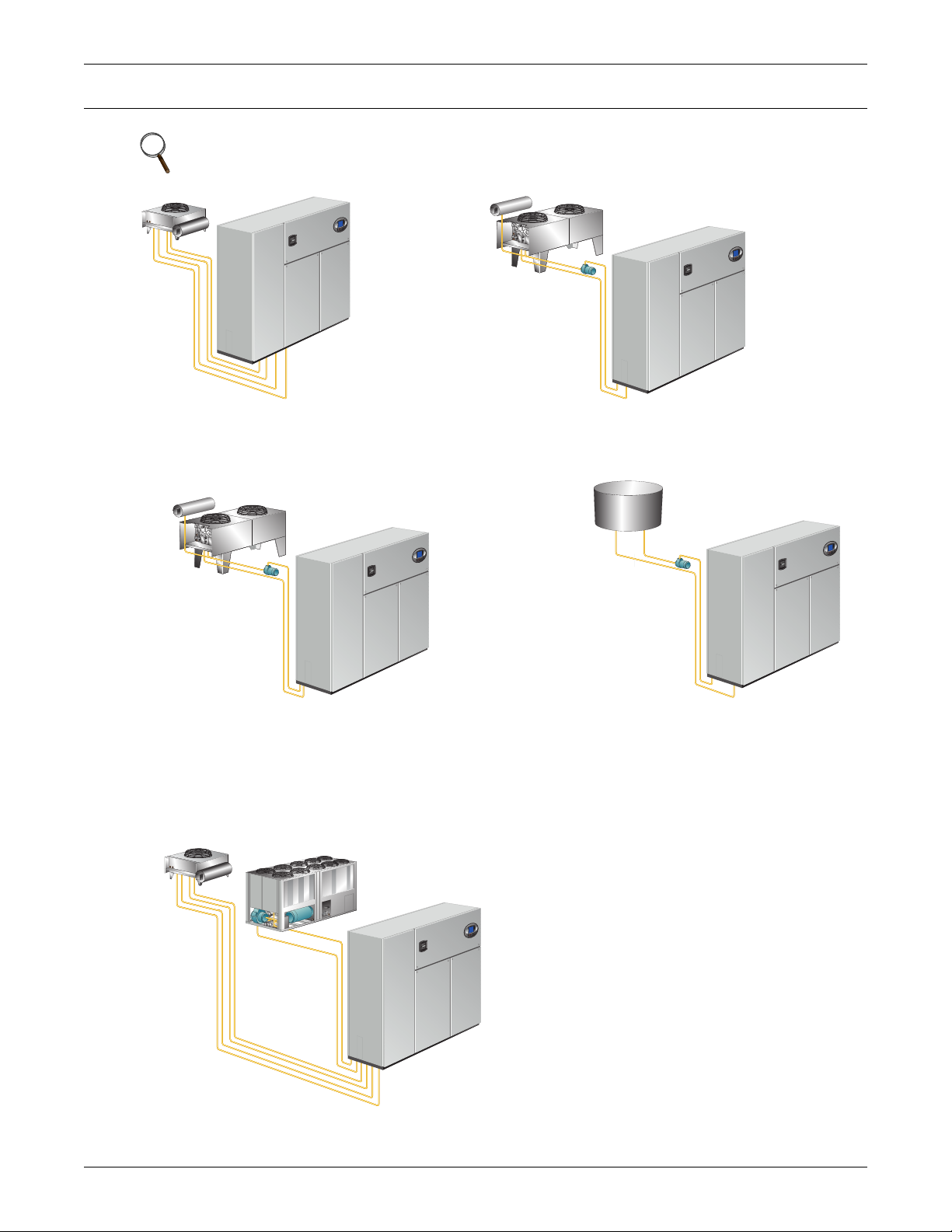
1.0 COOLING CONFIGURATIONS
AIR-COOLED
Air-cooled unit piping is spun closed from the
factory and contains a nitrogen holding charge.
Each installation requires field-supplied
refrigerant and piping to a condenser.
GLYCOL-COOLED
Glycol-cooled units are factory-charged and
tested. Field-supplied and field-installed piping is
required from the unit to the drycooler and pump
package.
WATER-COOLED
Water-cooled units are factory-charged and
tested. Field-supplied and field-installed
water piping is required from the unit to the
cooling tower.
GLYCOOL-INTEGRATED FLUID ECONOMIZER
GLYCOOL units are factory-charged and tested. Field-supplied
and field-installed piping is required from the unit to the
drycooler and pump package. An additional Liebert Economizer
coil is included for use when fluid temperatures are sufficiently
low (below room temperature). Economizer cooling is provided
by circulating cold glycol through this second coil, reducing or
eliminating compressor operation.
DUAL-COOL
This system has all of the features of a compressorized
system, but adds a second cooling coil that is connected
to a source of chilled water. Cooling is provided by
circulating chilled water, when available, through this
second coil and reducing compressor operation.
NOTE
All field-installed piping must comply with applicable local, state and federal codes.
Cooling Configurations
Liebert® DS
™
2
Page 7
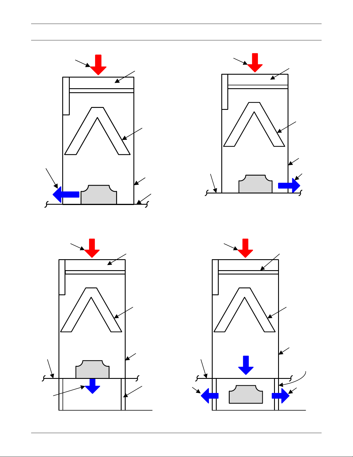
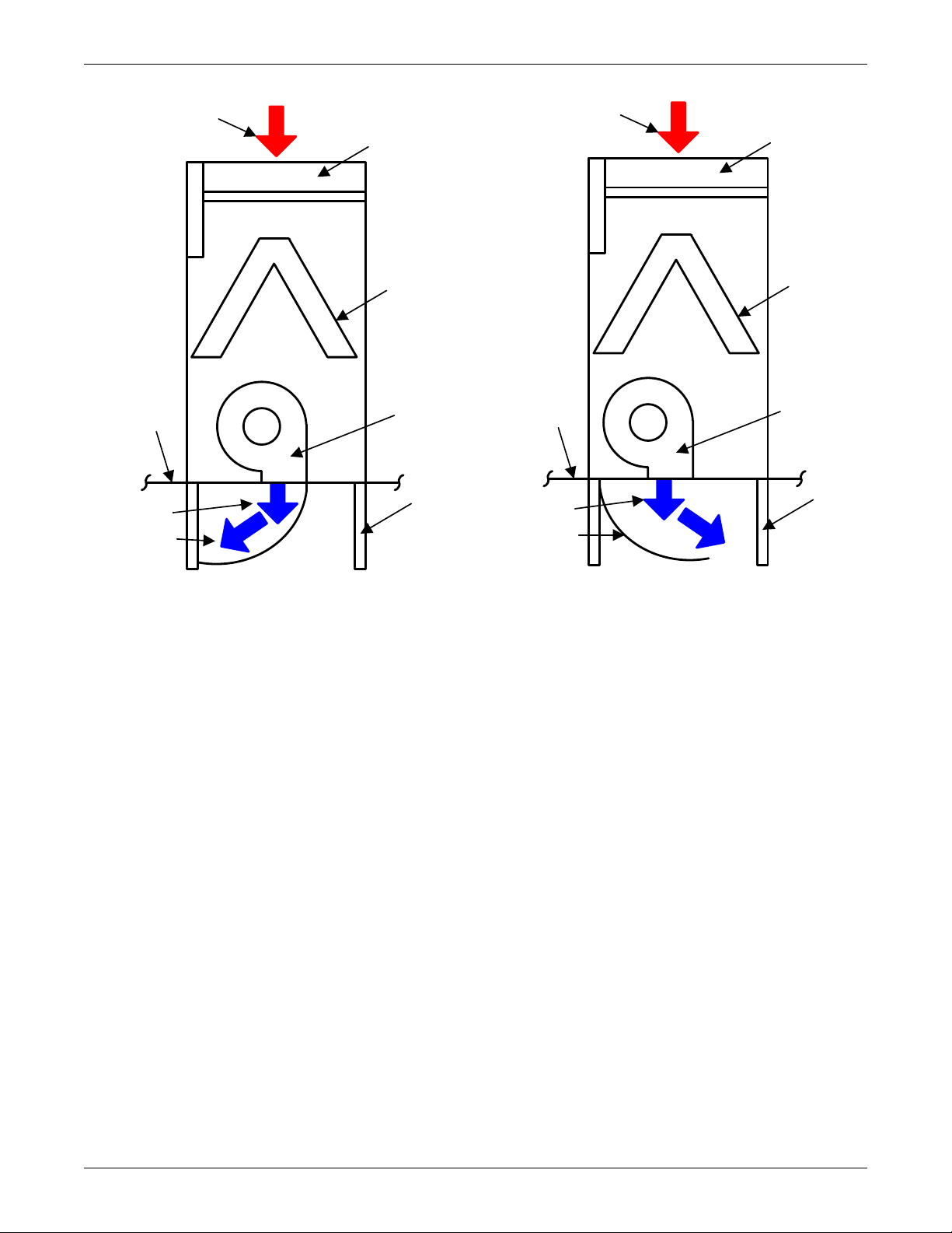
2.0 BLOWER CONFIGURATIONS
Front
Filter
Coil
Blower
Raised
Floor
Return Air
Supply
Air
Front Supply, EC Fans
Front
Filter
Coil
Blower
Raised
Floor
Return Air
Supply
Air
Rear Supply, EC Fans
Applicable to installations
without raised floors
Applicable to installations
without raised floors
Front
Filter
Coil
Blower
Floor
Stand
(optional )
Raised
Floor
Return Air
Supply
Air
Front
Filter
Coil
Blower
Floor Stand
(optional )
Raised
Floor
Return Air
Supply Air
Supply
Air
Under-Floor Supply, EC Fans
Bottom Supply, EC Fans
Figure 1 Blower configurations—Downflow, front and rear supply models, EC fans
Blower Configurations
Figure 2 Blower configurations—Downflow, bottom supply and under-floor supply models, EC fans
3Liebert
®
DS
™
Page 8
Blower Configurations
Front
Filter
Coil
Blower
Floor
Stand
(optional )
Raised
Floor
Return Air
Supply Air
Turning Vane
(optional )
Front Supply, Forward-Curved Fans
Front
Filter
Coil
Blower
Floor
Stand
(optional )
Raised
Floor
Return Air
Supply Air
Turning Vane
(optional )
Rear Supply, Forward-Curved Fans
Figure 3 Blower configurations—Downflow, front and rear supply models, centrifugal fans
Liebert® DS
™
4
Page 9
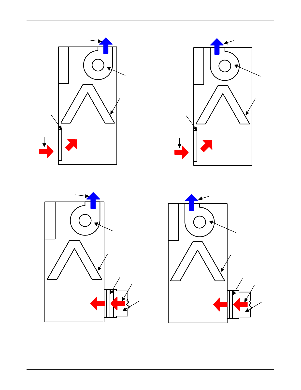
Figure 4 Blower configurations—Upflow, front return models, centrifugal fans
Front
Coil
Return
Air
Supply Air
Blow er
Filter
Front
Coil
Return
Air
Supply Air
Blow er
Filter
Top Supply, Front Throw Forward-Curved Fans Top Supply, Rear Throw Forward-Curved Fans
Front
Coil
Supply Air
Blower
Filter
Return
Air
Ductwork
Front
Coil
Supply Air
Blower
Filter
Return
Air
Ductwork
Top Supply, Rear Throw, Forward-Curved FansTop Supply, Front Throw, Forward-Curved Fans
Blower Configurations
Figure 5 Blower configurations—Upflow, rear return models, centrifugal fans
5Liebert
®
DS
™
Page 10
Air-Cooled Systems
3.0 AIR-COOLED SYSTEMS
3.1 CAPACITY AND PHYSICAL DATA
Table 1 Performance Data—Air-cooled, EC fan, under-floor discharge
Model Size 028 035 042 053 070 077 105
CAPACITY DATA with EC Fans
Net Capacity Data kW (BTUH), Standard Air Volume and Evaporator Fan Motor
Semi Hermetic Compressors with EC Fans
85°F DB, 64.5°F WB, 52.3°F DP (29.4°C DB, 18.1°C WB) 32.4% RH
Total kW (kBTUH) 34.1 (116.4) 42.1 (143.6) 47.9 (163.6) 61.7 (210.6) 72.4 (247.1) 79.2 (270.3) 103.3 (352.5)
Sensible kW
(kBTUH)
80°F DB, 62.9°F WB, 52.3°F DP (26.7°C DB, 17.1°C WB) 38.2% RH
Total kW (kBTUH) 32.4 (110.5) 40.1 (136.8) 45.7 (156.1) 58.3 (198.9) 68.8 (234.8) 75.3 (257.1) 99.1 (338.2)
Sensible kW
(kBTUH)
75°F DB, 61.1°F WB, 52.3°F DP (23.9°C DB, 16.2°C WB) 45.1% RH
Total kW (kBTUH) 30.9 (105.3) 38.3 (130.8) 43.8 (149.5) 55.4 (189) 65.6 (223.9) 72 (245.8) 95.2 (325)
Sensible kW
(kBTUH)
72°F DB, 60.0°F WB, 52.3°F DP (22.2°C DB, 15.6°C WB) 49.9% RH
Total kW (kBTUH) 30 (102.5) 37.3 (127.4) 42.7 (145.8) 53.8 (183.6) 63.9 (218) 70.2 (239.7) 93.1 (317.6)
Sensible kW
(kBTUH)
Net Capacity Data kW (BTUH), Standard Air Volume and Evaporator Fan Motor
Scroll or Digital Scroll Compressors with EC Fans
85°F DB, 64.5°F WB, 52.3°F DP (29.4°C DB, 18.1°C WB) 32.4% RH
Total kW (kBTUH) 35.4 (120.8) 40.2 (137.1) 45.5 (155.3) 63.5 (216.8) 75.8 (258.6) 81.3 (277.6) 103.6 (353.7)
Sensible kW
(kBTUH)
80°F DB, 62.9°F WB, 52.3°F DP (26.7°C DB, 17.1°C WB) 38.2% RH
Total kW (kBTUH) 33.4 (113.9) 38.2 (130.4) 43.4 (148.1) 60.5 (206.5) 72.7 (248) 77.9 (265.8) 99.7 (340.2)
Sensible kW
(kBTUH)
75°F DB, 61.1°F WB, 52.3°F DP (23.9°C DB, 16.2°C WB) 45.1% RH
Total kW (kBTUH) 31.6 (107.8) 36.5 (124.7) 41.6 (141.9) 57.8 (197.4) 69.9 (238.4) 74.9 (255.5) 96 (327.8)
Sensible kW
(kBTUH)
72°F DB, 60.0°F WB, 52.3°F DP (22.2°C DB, 15.6°C WB) 49.9% RH
Total kW (kBTUH) 30.6 (104.3) 35.6 (121.5) 40.6 (138.5) 56.4 (192.6) 68.3 (233) 73.2 (249.9) 93.8 (320.3)
Sensible kW
(kBTUH)
Standard Air
Volume,
CFM (CMH)
0.2" External Static
Standard Fan
Motor,
Nominal kW
(total for all fans)
Number of Fans 1 1 1 2 2 2 3
1. Capacity data is rated and factory-certified per ASHRAE 127-2012 with a 5% tolerance.
2. Some options or combinations of options may result in reduced air flow—consult factory for recommendations.
3. Digital scroll not available on 077 and 105 models; units available with semi-hermetic and standard scroll compressors only.
34 (116) 41.4 (141.2) 47.9 (160.9) 61.6 (210.2) 72 (245.9) 78.9 (269.2) 98.9 (337.5)
31 (105.9) 37.5 (128.1) 45.7 (146.2) 56.8 (193.9) 66.4 (226.6) 72.9 (248.8) 90 (307.2)
27.5 (93.9) 33.3 (113.8) 43.8 (129.9) 50.8 (173.3) 59 (201.3) 64.9 (221.5) 80 (273.1)
25.3 (86.3) 30.7 (104.8) 42.7 (119.7) 46.7 (159.3) 54.2 (184.9) 59.7 (203.6) 73.8 (251.8)
Scroll Compressors Only
35.2 (120) 40 (136.4) 45.3 (154.7) 63.2 (215.7) 74.9 (255.6) 80.6 (275.1) 99.1 (338.3)
31.8 (108.7) 36.5 (124.6) 41.6 (141.9) 58.3 (199.1) 68.9 (235) 74.1 (253) 90.3 (308.2)
28.2 (96.1) 32.5 (110.8) 37 (126.3) 52 (177.6) 61.4 (209.4) 65.9 (224.9) 80.4 (274.3)
25.8 (88.2) 29.9 (102.1) 34.1 (116.3) 47.9 (163.6) 56.5 (192.9) 60.6 (206.9) 74.1 (253)
FAN SECTION - Downflow Models - EC Fans Under Floor
4,400
(7,476)
2.8 2.8 2.8 2.5 4.0 5.9 7.8
5,200
(8,835)
6200
(10533.9)
8,000
(13,592)
9,600
(16,310)
11,000
(18,689)
13,700
(23,276)
Liebert® DS
™
6
Page 11
Air-Cooled Systems
Table 2 Performance data—Air-cooled, centrifugal fan
Model Size 028 035 042 053 070 077 105
CAPACITY DATA with Centrifugal Fans
Net Capacity Data kW (BTUH), Standard Air Volume and Evaporator Fan Motor
Semi Hermetic Compressors with Centrifugal Fans
85°F DB, 64.5°F WB, 52.3°F DP (29.4°C DB, 18.1°C WB) 32.4% RH
Total kW (kBTUH) 40.3 (137.6) 41.0 (140.0) 46.2 (157.6) 60.2 (205.3) 70.5 (240.6) 76.9 (262.6) 101.3 (345.6)
Sensible kW
(kBTUH)
38.0 (129.6) 40.3 (137.6) 45.5 (155.3) 59.7 (203.8) 69.7 (237.9) 76.2 (259.9) 96.6 (329.6)
80°F DB, 62.9°F WB, 52.3°F DP (26.7°C DB, 17.1°C WB) 38.2% RH
Total kW (kBTUH) 38.6 (131.8) 39.1 (133.3) 43.9 (150) 57.2 (195.1) 67.2 (229.3) 73.4 (250.6) 97.1 (331.5)
Sensible kW
(kBTUH)
34.3 (117.2) 36.5 (124.6) 41.2 (140.5) 54.8 (187.1) 63.8 (217.7) 69.8 (238.2) 87.7 (299.4)
75°F DB, 61.1°F WB, 52.3°F DP (23.9°C DB, 16.2°C WB) 45.1% RH
Total kW (kBTUH) 37.1 (126.5) 37.3 (127.2) 42 (143.3) 54.4 (185.6) 64.1 (218.9) 70.2 (239.7) 93.3 (318.4)
Sensible kW
(kBTUH)
30.5 (104.2) 32.3 (110.3) 36.4 (124.2) 48.7 (166.2) 56.5 (192.9) 61.8 (210.9) 77.8 (265.4)
72°F DB, 60.0°F WB, 52.3°F DP (22.2°C DB, 15.6°C WB) 49.9% RH
Total kW (kBTUH) 36.1 (123.3) 36.3 (123.8) 40.9 (139.6) 52.9 (180.6) 62.5 (213.2) 68.6 (234) 91.0 (310.6)
Sensible kW
(kBTUH)
28.2 (96.3) 29.7 (101.3) 33.4 (113.9) 44.7 (152.7) 51.9 (177.2) 56.7 (193.6) 71.5 (244.1)
Net Capacity Data kW (BTUH), Standard Air Volume and Evaporator Fan Motor
Scroll or Digital Scroll Compressors with Centrifugal Fans
85°F DB, 64.5°F WB, 52.3°F DP (29.4°C DB, 18.1°C WB) 32.4% RH
Total kW (kBTUH) 34.1 (116.4) 39.7 (135.5) 43.7 (149.2) 62.1 (212.1) 74.0 (252.6) 79.1 (270.1) 101.6 (346.9)
Sensible kW
(kBTUH)
40.1 (136.9) 34.0 (116.0) 43.6 (148.9) 61.3 (209.3) 72.3 (246.6) 77.8 (265.6) 96.8 (330.4)
80°F DB, 62.9°F WB, 52.3°F DP (26.7°C DB, 17.1°C WB) 38.2% RH
Total kW (kBTUH) 32.4 (110.5) 38.3 (130.8) 41.6 (141.9) 59.3 (202.5) 71.2 (243) 75.9 (259) 97.7 (333.5)
Sensible kW
(kBTUH)
31.0 (105.9) 36.1 (123.2) 39.9 (136.1) 56.1 (191.6) 65.9 (225) 71.1 (242.6) 88.0 (300.4)
75°F DB, 61.1°F WB, 52.3°F DP (23.9°C DB, 16.2°C WB) 45.1% RH
Total kW (kBTUH) 30.9 (105.3) 36.7 (125.4) 39.8 (135.7) 56.9 (194.2) 68.5 (233.9) 73 (249.3) 94.1 (321.1)
Sensible kW
(kBTUH)
27.5 (93.9) 32.1 (109.4) 35.3 (120.6) 49.9 (170.4) 58.6 (200.1) 63.1 (215.2) 78.1 (266.6)
72°F DB, 60.0°F WB, 52.3°F DP (22.2°C DB, 15.6°C WB) 49.9% RH
Total kW (kBTUH) 30.0 (102.5) 35.9 (122.4) 38.8 (132.3) 55.5 (189.5) 67 (228.7) 71.4 (243.7) 91.9 (313.7)
Sensible kW
(kBTUH)
25.3 (86.3) 29.5 (100.6) 32.4 (110.5) 46.0 (157) 54.0 (184.3) 58.0 (197.8) 71.9 (245.5)
FAN SECTION - Downflow Models - Fixed Pitch, Two Belts
Standard Air
Volume - CFM
(CMH) 0.2"
4,400
(7,476)
5,200
(8,835)
6,300
(10,704)
7,500
(12,743)
9,000
(15,291)
external static
Standard Fan
Motor hp (kW)
2 (1.5) 3 (2.2) 5.0 (3.7) 3 (2.2) 5 (3.7) 7.5 (5.6) 10.0 (7.5)
Number of Fans 1 1 1 2 2 2 3
1. Capacity data is rated and factory-certified per ASHRAE 127-2012 with a 5% tolerance.
2. Some options or combinations of options may result in reduced air flow—consult factory for recommendations.
3. Digital scroll not available on 077 and 105 models; units available with semi-hermetic and standard scroll compressors only
Scroll Compressors Only
10,400
(17,670)
13,700
(23,276)
®
7Liebert
DS
™
Page 12
Air-Cooled Systems
Table 3 Physical data—Air-cooled systems
Model Size 028 035 042 053 070 077 105
EVAPORATOR COIL- A-Frame - Copper Tube/Aluminum Fin
Face Area, sq. ft. (sq. m)
Rows of Coil
Electric Reheat - Three-Stage, Stainless Steel Fin Tubular, capacity does not include fan motor heat
Capacity - kW (kBTUH) - Standard
Selection
Capacity, kW (kBTUH) - Optional
Selection
Electric Reheat - SCR Control, Stainless Steel Fin Tubular (optional selection)
Capacity, kW (kBTUH)
Infrared Humidifier (Steam canister humidifiers available on downflow models with centrifugal fans)
Capacity, lb./hr. (kg/h)
FILTER SECTION - Disposable Type - Nominal Sizes and Quantities, Standard MERV 8 or Optional MERV 11
(filter types cannot be mixed, must be all MERV 8 or all MERV 11)
Downflow Models
Quantity
Nominal Size, inches
Upflow Models (Front & Rear return) Filters located in separate filter box on rear return, located on lower unit panel
Quantity
Nominal Size, inches 25x20 25x20 25x20 25x20 25x20 25x20 25x20
PIPING CONNECTION SIZES - Air-cooled Liebert DS Indoor Unit (Not External Line Sizes)
Liquid Line, O.D. Copper (2/unit) 1/2 1/2 1/2 5/8 5/8 5/8 5/8
Hot Gas Line, O.D. Copper (2/unit) 5/8 5/8 5/8 7/8 7/8 7/8 1-1/8
Infrared Humidifier, O.D. Copper
Condensate Drain, FPT
Condensate Drain w/Optional
Condensate Pump, OD
OUTDOOR AIR-COOLED CONDENSER, STANDARD 95°F AMBIENT SELECTION; see Tables 44 and 49 for other selections
Model (R-407C refrigerant) MCM080_8 MCM080_8 MCM080_8 MCM080_8 MCM080_8 MCM080_8 MCL110_8
Number of Fans 222 2 2 2 2
DUAL-COOL UNITS DATA, Water (0% Glycol), Net Capacity Data kW (kBTUH)
CAUTION: CuNi coil option must be specified when Econ-O-Coil is applied to open water tower.
75°F DB, 61.1 WB (23.9°C DB, 16.2°C WB) 45% RH, 45°F EWT, 55°F LWT Based on Centrifugal Fans
Total Capacity, kW (kBTUH)
Sensible Capacity, kW (kBTUH) 24.9 (85) 28.8 (98.2) 31.6 (107.8) 46 (157.1) 51.7 (176.4) 54.3 (185.4)
Flow Rate GPM (I/m) @ 10°F Rise 19 (71.9) 22.4 (84.8) 25.5 (96.5) 36.4 (138) 41.7 (158) 46 (174)
Pressure Drop, ft. (kPa), valve, coil 6.1 (18.23) 8.3 (24.81)
Airflow, CFM (CMH) 4400 (7475) 5500 (9344)
Econ-O-Coil fluid volume, gal (l)
Capacity data is rated per ASHRAE 127-2012 with a 5% tolerance
17.1 (1.6) 17.1 (1.6) 17.1 (1.6) 24.7 (2.3) 24.7 (2.3) 24.7 (2.3) 32.3 (3.0)
333 3 3 3 3
REHEAT SECTION
15.0 (51.2) 15.0 (51.2) 15.0 (51.2) 25.0 (85.3) 25.0 (85.3) 25.0 (85.3) 30.0 (102.4)
10.0 (34.1) 10.0 (34.1) 10.0 (34.1) 15.0 (51.2) 15.0 (51.2) 15.0 (51.2) 20.0 (68.3)
15.0 (51.2) 15.0 (51.2) 15.0 (51.2) 25.0 (85.3) 25.0 (85.3) 25.0 (85.3) 30.0 (102.4)
HUMIDIFIER SECTION
11.0 (5.0) 11.0 (5.0) 11.0 (5.0) 22.0 (10.0) 22.0 (10.0) 22.0 (10.0) 22.0 (10.0)
333 4 4 4 4
2 @ 25x20
1 @ 25x16
444 6 6 6 8
1/4 1/4 1/4 1/4 1/4 1/4 1/4
3/4 3/4 3/4 3/4 3/4 3/4 3/4
1/2 1/2 1/2 1/2 1/2 1/2 1/2
26.2 (89.2) 29.8 (101.6) 32.2 (109.8) 49.9 (170.4) 55.3 (188.8) 57.7 (196.8)
2 @ 25x20
1 @ 25x16
2 @ 25x20
1 @ 25x16
10.50 (31.39) 10.40 (31.09)
6600
(11213)
4 @ 25x20 4 @ 25x20 4 @ 25x20 4 @ 25x20
8000
(13592)
13.3 (39.8) 15.9 (47.6)
9600
(16310)
11000
(18689)
75.8 (258.8)
73 (249.1)
59.4 (225)
15.9 (47.5)
13,700
(23,256)
Fluid Volumes
5 (19.0) 5 (19.0) 5 (19.0) 8 (30.4) 8 (30.4) 8 (30.4) 10 (38.0)
Liebert® DS
™
8
Page 13
Table 4 Electrical data—Air-cooled systems with EC fans
Air-Cooled Systems
Reheat
Options
Humid-
ifier
Options Infrared Infrared None None Humidifier No Humidifier
Model
#
Volts 208 230 460 575 208 230 460 575 208 230 460 575 208 230 460 575 208 230 460 575 208 230 460 575
FLA 67.3 64.8 32.1 25.5 56.3 54.1 26.9 24.2 67.3 64.8 32.1 25 43 43 21.1
DS028
WSA 82 78.9 39.2 31.9 60.6 58.4 29.1 25.9 82 78.9 39.2 30.5 47.3 47.3 23.3
OPD 80804030707035308080403060 6030
FLA 70.7 68.2 33.4 25.5 63.1 60.9 29.5 25.2 70.7 68.2 33.4 25.5 49.8 49.8 23.7
DS035
WSA 86.3 83.2 40.8 31.9 68.3 66.1 32 27.1 86.3 83.2 40.8 31.1 55 55 26.2
OPD 90904530808040309090453070 7035
FLA 78.2 75.9 37.7 33 78.1 75.9 37.7 33 78.2 75.7 37.5 29.4 64.8 64.8 31.9
DS042
WSA 95.7 92.5 46 36 85.2 83 41.2 35.8 95.7 92.5 46 36 71.9 71.9 35.4
OPD 110 110 50 45 110 110 50 45 110 110 50 40 100 100 45
FLA 119.9 116 57.1 43.5 109.2 104.8 52.4 42 119.9 116 57.1 43.5 82.6 82.6 40.8
DS053
WSA 145.3 140.4 69.4 53.9 117.2 112.8 56.5 45 145.3 140.4 69.4 52.8 90.6 90.62 44.9
OPD 150 150 70 50 125 125 70 50 150 150 70 50 110 110 60
FLA 129.2 125.3 59.9 46.4 127.8 123.4 58 46.4 129.2 125.3 59.9 45.7 101.2 101.2 46.4
DS070
WSA 156.9 152 72.9 55.5 138.2 133.8 62.8 50 156.9 152.0 72.9 55.5 111.6 111.6 51.2
OPD 175 175 80 60 175 175 80 60 175 175 80 60 150 150 70
FLA 139.2 134.8 61.4 50 139.2 134.8 61 50 134.9 131 61.4 47.5 112.6 112.6 49.4
DS077
WSA 164 159.2 74.8 57.8 151. 146.6 66.2 54 164.0 159.2 74.8 57.8 124.37 124.4 54.6
OPD 175 175 80 70 175 175 80 70 175 175 80 60 150 150 70
FLA 171.5 167.1 83.7 69.1 171.5 167.1 83.7 69.1 164 163.5 79.8 62.6 144.9 144.9 72.1
WSA 198.8 198.2 97.4 76.4 186.5 182.1 91.6 75.4 198.8 198.2 97.4 76.4 159.9 159.9 80
DS105
OPD 225 225 110 100 225 225 110 100 225 225 110 90 200 200 110
1. Reduced reheat for 028, 035, and 042 models is 10kW.
2. Reduced reheat for 053, 070, and 077 models is 15kW.
3. Consult local representative for SCR reheat values.
4. Reduced reheat for 105 kW models is 20kW.
5. SCCR - Short Circuit Current Rating 65,000 amps rms symmetrical maximum.
6. Steam canister humidifiers not available on models with EC fans.
Electric
Standard, kW None
Electric
Standard kW None
16.8 56.3
18.5 64.8
25 70
17.8 63.1
19.7 69
25 80
25.6 78.1
28.4 85.2
35 110
30.4 109.2
33.4 117.2
45 125
34.8 127.8
38.4 138.2
50 175
38.4 139.2
42.4 151
50 175
57.5 171.5
63.8 186.5
80 225
Electric,
Downsized kW
54.1 26.9 24.2 53.5 51.9 25.6 19.9
62.8 31.1 25.9 64.8 62.8 31.1 24.1
70 35 30 70 70 35 25
60.9 29.5 25.2 56.9 55.3 26.9 20.4
67 32.7 27.1 69 67 32.7 24.8
80 40 30 80 80 35 25
75.9 37.7 33 64.8 64.8 31.9 25.6
83 41.2 35.8 78.4 76.4 37.8 29.6
110 50 45 100 100 45 35
104.8 52.4 42 92.1 89.6 44.1 33.5
112.8 56.5 45 110.52 107.4 53.1 40.3
125 70 50 125 125 60 45
123.4 58 46.4 101.4 101.2 46.9 35.7
133.8 62.8 50 122.15 119.02 56.6 43
175 80 60 150 150 70 50
134.8 61 50 112.6 112.6 49.4 38.4
146.6 66.2 54 129.27 126.15 58.5 45.3
175 80 70 150 150 70 50
167.1 83.7 69.1 144.9 144.9 72.1 57.5
182.1 91.6 75.4 169.3 165.5 81.3 63.9
225 110 100 200 200 110 80
Electric,
Downsized kW
®
9Liebert
DS
™
Page 14
Air-Cooled Systems
Table 5 Electrical data—Air-cooled systems with centrifugal fans
Reheat Options Electric, Std. kW None Electric, Std. kW None
Humidifier
Options
Motor
Model
hp Volts 208 230 460 575 208 230 460 575 208 230 460 575 208 230 460 575
FLA 66.4 63.2 31.8 25.2 55.4 52.5 26.6 23.9 66.4 63.2 31.8 24.7 42.1 41.4 20.8 16.5
028 2.0
WSA 81.1 77.3 38.9 31.5 59.7 56.8 28.8 25.6 81.1 77.3 38.9 30.2 46.4 45.7 23 18.2
OPD80804030707035308080403060603025
FLA 69.5 66.0 33.2 26.4 58.5 55.3 28.0 25.1 69.5 66.0 33.2 25.9 45.2 44.2 22.2 17.7
028 3.0
WSA 84.2 80.1 40.3 33 62.8 59.6 30.2 26.8 84.2 80.1 40.3 31.4 49.5 48.5 24.4 19.4
OPD90804030807035309080403060603025
FLA 72.9 69.4 34.5 26.4 65.3 62.1 30.6 26.1 72.9 69.4 34.5 26.4 52.0 51.0 24.8 18.7
035 3.0t
WSA 88.5 84.4 41.9 33.0 70.5 67.3 33.1 28.0 88.5 84.4 41.9 32.0 57.2 56.2 27.3 20.6
OPD90904535908040359090453570703525
FLA 79.0 75.0 37.3 28.6 71.4 67.7 33.4 28.3 79.0 75.0 37.3 28.6 58.1 56.6 27.6 20.9
035 5.0
WSA 94.6 90.0 44.7 35.8 76.6 72.9 35.9 30.2 94.6 90.0 44.7 34.2 63.3 61.8 30.1 22.8
OPD 100 100 45 35 90 90 45 35 100 100 45 35 80 80 40 30
FLA 86.5 82.7 41.6 36.1 86.4 82.7 41.6 36.1 86.5 82.5 41.4 32.5 73.1 71.6 35.8 28.7
042 5.0
WSA 104 99.3 49.9 39.1 93.5 89.8 45.1 38.9 104.0 99.3 49.9 39.1 80.2 78.7 39.3 31.5
OPD 110 110 50 50 110 110 50 50 110 110 50 45 100 100 50 40
FLA 94.0 89.5 45.0 39.0 93.9 89.5 45.0 39.0 94.0 89.3 44.8 35.4 80.6 78.4 39.2 31.6
042 7.5
WSA 111.5 106.1 53.3 42.0 101.0 96.6 48.5 41.8 111.5 106.1 53.3 42.0 87.7 85.5 42.7 34.4
OPD 125 110 60 50 125 110 60 50 125 110 60 45 110 110 50 45
FLA 112.1 107.2 53.9 41 101.4 96 49.2 39.5 112.1 107.2 53.9 41 74.8 73.8 37.6 27.9
053 3.0
WSA 137.5 131.6 66.2 50.8 109.4 104.0 53.3 42.5 137.5 131.6 66.2 50.3 82.8 81.8 41.7 30.9
OPD 150 125 70 50 125 125 60 50 150 125 70 50 110 110 50 40
FLA 118.2 112.8 56.7 43.2 107.5 101.6 52.0 41.7 118.2 112.8 56.7 43.2 80.9 79.4 40.4 30.1
053 5.0
WSA 143.6 137.2 69.0 53.5 115.5 109.6 56.1 44.7 143.6 137.2 69.0 52.5 88.9 87.4 44.5 33.1
OPD 150 150 70 50 125 125 70 50 150 150 70 50 110 110 60 45
FLA 127.5 122.1 59.5 46.1 126.1 120.2 57.6 46.1 127.5 122.1 59.5 45.4 99.5 98 46 34.5
070 5.0
WSA 155.2 148.8 72.5 55.2 136.5 130.6 62.4 49.7 155.2 148.8 72.5 55.2 109.9 108.4 50.8 38.1
OPD 175 150 80 60 175 150 80 60 175 150 80 60 150 125 70 50
FLA 135.0 128.9 62.9 49.0 133.6 127.0 61.0 49.0 135.0 128.9 62.9 48.3 107.0 104.8 49.4 37.4
070 7.5
WSA 162.7 155.6 75.9 58.1 144.0 137.4 65.8 52.6 162.7 155.6 75.9 58.1 117.4 115.2 54.2 41.0
OPD 175 175 80 60 175 175 80 60 175 175 80 60 150 150 70 50
FLA 145 138.4 64.4 52.6 145.0 138.4 64.0 52.6 140.7 134.6 64.4 50.1 118.4 116.2 52.4 41.0
077 7.5
WSA 169.8 162.8 77.8 60.4 156.8 150.2 69.2 56.6 169.8 162.8 77.8 60.4 130.2 128.0 57.6 45.0
OPD 200 175 90 70 200 175 80 70 175 175 90 70 175 175 70 60
FLA 151.6 144.4 67.4 54.6 151.6 144.4 67.0 54.6 147.3 140.6 67.4 52.1 125.0 122.2 55.4 43.0
077 10.0
WSA 176.4 168.8 80.8 62.4 163.4 156.2 72.2 58.6 176.4 168.8 80.8 62.4 136.8 134.0 60.6 47.0
OPD 200 200 90 70 200 200 90 70 200 175 90 70 175 175 80 60
FLA 177.4 170.2 88.4 72.6 177.4 170.2 88.4 72.6 169.9 166.6 84.5 66.1 150.8 148 76.8 61.0
105 10.0
WSA 204.7 201.3 102.1 79.9 204.7 201.3 102.1 79.9 204.7 201.3 102.1 79.9 165.8 163.0 84.7 67.3
OPD 250 225 125 100 250 225 125 100 225 225 110 90 225 200 110 90
FLA 192.3 184.2 95.4 78.6 192.3 184.2 95.4 78.6 185.3 180.6 91.5 72.1 166.2 162.0 83.8 67.0
105 15.0
WSA 220.1 215.3 109.1 85.9 220.1 215.3 109.1 85.9 220.1 215.3 109.1 85.9 181.2 177.0 91.7 73.3
OPD 250 250 125 100 250 250 125 100 250 250 125 100 225 225 110 90
1. Reduced reheat for 028, 035, and 042 models is 10kW.
2. Reduced reheat for 053, 070, and 077 models is 15kW.
3. Consult local representative for SCR reheat values.
4. Reduced reheat for 105 kW models is 20kW.
5. SCCR - Short Circuit Current Rating 65,000 amps rms symmetrical maximum.
Infrared or Steam
Generating Canister
Infrared or Steam
Generating Canister None None
Liebert® DS
™
10
Page 15
Table 5 Electrical data—Air-cooled systems with centrifugal fans (continued)
Reheat Options Electric, Downsized kW
Humidifier Options Infrared or Steam Generating Canister None
Model Motor, hp Volts 208 230 460 575 208 230 460 575
FLA 55.4 52.5 26.6 23.9 52.6 50.3 25.3 19.6
028 2.0
028 3.0
035 3.0
035 5.0
042 5.0
042 7.5
053 3.0
053 5.0
070 5.0
070 7.5
077 7.5
077 10.0
105 10.0
105 15.0
1. Reduced reheat for 028, 035, and 042 models is 10kW.
2. Reduced reheat for 053, 070, and 077 models is 15kW.
3. Consult local representative for SCR reheat values.
4. Reduced reheat for 105 kW models is 20kW.
5. SCCR - Short Circuit Current Rating 65,000 amps rms symmetrical maximum.
WSA 63.9 61.2 30.8 25.6 63.9 61.2 30.8 23.8
OPD 70 70 35 30 70 70 35 25
FLA 58.5 55.3 28 25.1 55.7 53.1 26.7 20.8
WSA 67.0 64.0 32.2 26.8 67.0 64.0 32.2 25.0
OPD 80 70 35 30 70 70 35 25
FLA 65.3 62.1 30.6 26.1 59.1 56.5 28.0 21.3
WSA 71.2 68.2 33.8 28.0 71.2 68.2 33.8 25.7
OPD 90 80 40 35 80 80 40 30
FLA 71.4 67.7 33.4 28.3 65.2 62.1 30.8 23.5
WSA 77.3 73.8 36.6 30.2 77.3 73.8 36.6 27.9
OPD 90 90 45 35 90 80 40 30
FLA 86.4 82.7 41.6 36.1 73.1 71.6 35.8 28.7
WSA 93.5 89.8 45.1 38.9 86.7 83.2 41.7 32.7
OPD 110 110 50 50 100 100 50 40
FLA 93.9 89.5 45.0 39.0 80.6 78.4 39.2 31.6
WSA 101.0 96.6 48.5 41.8 94.2 90.0 45.1 35.6
OPD 125 110 60 50 110 110 50 45
FLA 101.4 96.0 49.2 39.5 84.3 80.8 40.9 31
WSA 109.4 104.0 53.3 42.5 102.7 98.6 49.9 37.8
OPD 125 125 60 50 110 110 60 45
FLA 107.5 101.6 52.0 41.7 90.4 86.4 43.7 33.2
WSA 115.5 109.6 56.1 44.7 108.8 104.2 52.7 40.0
OPD 125 125 70 50 125 125 60 45
FLA 126.1 120.2 57.6 46.1 99.7 98 46.5 35.4
WSA 136.5 130.6 62.4 49.7 120.5 115.8 56.2 42.7
OPD 175 150 80 60 150 125 70 50
FLA 133.6 127.0 61.0 49.0 107.2 104.8 49.9 38.3
WSA 144.0 137.4 65.8 52.6 128.0 122.6 59.6 45.6
OPD 175 175 80 60 150 150 70 50
FLA 145 138.4 64.0 52.6 118.4 116.2 52.4 41.0
WSA 156.8 150.2 69.2 56.6 135.1 129.8 61.5 47.9
OPD 200 175 80 70 175 175 70 60
FLA 151.6 144.4 67.0 54.6 125.0 122.2 55.4 43.0
WSA 163.4 156.2 72.2 58.6 141.7 135.8 64.5 49.9
OPD 200 200 90 70 175 175 80 60
FLA 177.4 170.2 88.4 72.6 150.8 148 76.8 61.0
WSA 192.4 185.2 96.3 78.9 175.2 168.6 86.0 67.4
OPD 250 225 125 100 225 200 110 90
FLA 192.8 184.2 95.4 78.6 166.2 162.0 83.8 67.0
WSA 207.8 199.2 103.3 84.9 190.6 182.6 93.0 73.4
OPD 250 250 125 100 225 225 110 90
Air-Cooled Systems
11 Liebert® DS
™
Page 16
Air-Cooled Systems
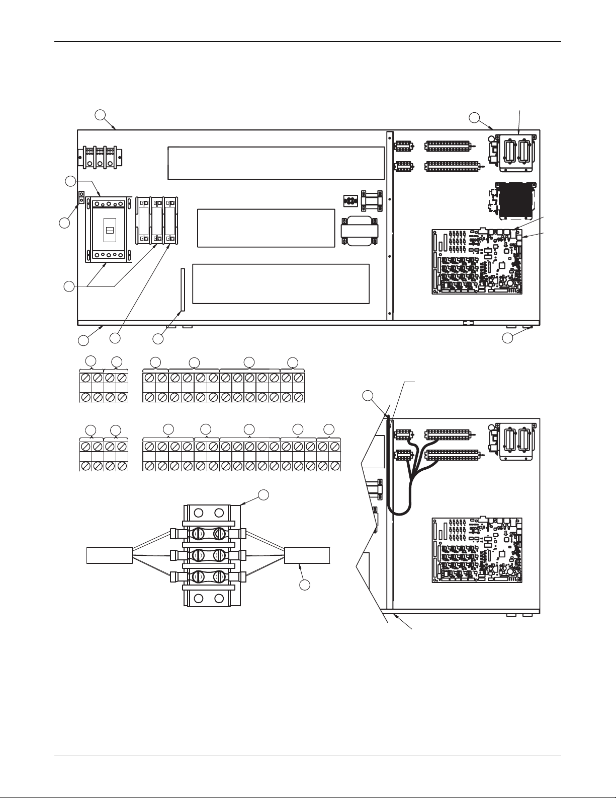
See 3.2 - Standard Electrical Connections, 3.3 Optional Electrical Connections and 3.4 - Optional
Low-Voltage Terminal Package Connections for keys
to numbered components.
Figure 6 Electrical field connections—Upflow and downflow models, single molded case switch
disconnect with main fuses
2
4
Liebert
IntelliSlot
Housing
15
6
60Hz
13
17
5
18
83
88
1
82 89
A
24
23
OVERCURRENT PROTECTION DEVICES
CONTACTORS
CONTACTORS, RELAYS, &
OVERLOAD PROTECTORS
Typical orientation of components shown.
6
Component location varies by option and unit size
9
7576949596 97 91
22
16
92
93
80
19
81
12
11
UPFLOW
B
21
7
8
10
20
A
B
CD
Alternate
Location
P64
P67
E
DOWNFLOW
3
DOWNFLOW LOW-VOLT SECTION
CAUTION
Risk of broken or shorted low-voltage
3
wiring. Field-installed low-voltage wiring
must be routed with loop as shown
to allow electric box to swing.
50
59
84
58 85
37C
38C
37B
38B
37 38 24
51
56
55
7071230
CD
11
SH49-1
49-3
12
Item 12 Installation Conditions
1. Follow all local installation codes.
2. Do not run CAN cables in same conduit, raceway, or
chase as high voltage wires (120-600V).
3. Separate high-voltage wires from CAN wires by 12" (305mm).
4. For runs greater than 350ft (107m), contact Emerson factory.
E
73
72
Point of Hinged Low-Voltage Electric Box
DS UPFLOW LOW VOLT SECTION
DPN000807
Pg. 2, Rev. 8
Liebert® DS
™
12
Page 17
Air-Cooled Systems
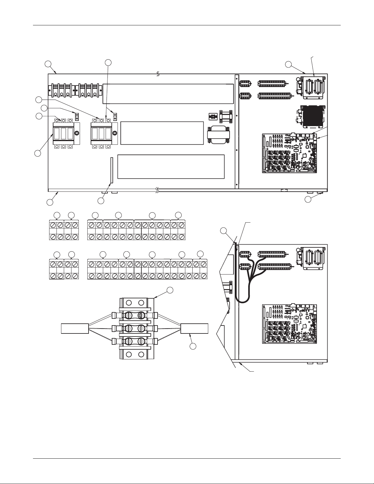
See 3.2 - Standard Electrical Connections, 3.3 Optional Electrical Connections and 3.4 - Optional
Low-Voltage Terminal Package Connections for keys
to numbered components.
Figure 7 Electrical field connections—Upflow and downflow models, dual fused disconnect switches
Liebert
2
14
4
IntelliSlot
Housing
15
15
13
60 Hz
6
1
17 18
82 89
24
PRIMARY
83
A
B
Alternate
Alternate
Location
Location
P64
P67
OVERCURRENT PROTECTION DEVICES
SECONDARY
CONTACTORS
A
CD
CONTACTORS, RELAYS and
OVERLOAD PROTECTORS
E
Typical orientation of components shown.
6
Component location varies by option and unit size
9
22
16
19
DOWNFLOW LOW-VOLTAGE SECTION
UPFLOW
92
88
7576949596 97 91
93
80
81
12
11
3
DOWNFLOW
CAUTION:
Risk of broken or shorted low-voltage
wiring. Field-installed low-voltage wiring
must be routed with loop as shown
to allow electric box to swing.
3
B
23
21
7
8
10
20
50
E
51
56
55
7071230
11
SH49-1
49-3
72
12
37C
37B
59
84
58 85
38C
38B
37 38 24
CD
Item 12 Installation Conditions
1. Follow all local installation codes.
2. Do not run CAN cables in same conduit, raceway or
chase as high-voltage wires (120-600V).
3. Separate high-voltage wires from CAN wires by 12" (305mm).
4. Contact Liebert factory for runs greater than 350ft. (107m).
5. All electrical loads may not be capable of being connected to both
power feeds, with automatic transfer switch.
Consult local representative for dual power configurations available.
73
Point of Hinged Low-Voltage
Electric Box
DS UPFLOW LOW-VOLTAGE SECTION
DPN000807
Pg. 3, Rev. 8
13 Liebert® DS
™
Page 18

3.2 STANDARD ELECTRICAL CONNECTIONS
Source: DPN000807, Rev. 8
1. Primary high voltage entrance—2.5" (64mm); 1.75" (44mm); 1.375" (35mm) diameter
concentric knockouts located in bottom of box.
2. Secondary high voltage entrance—2.5" (64mm); 1.75" (44mm); 1.375" (35mm) diameter
concentric knockouts located in top of box.
3. Primary low voltage entrance—Quantity (3) 1.375" (35mm) diameter knockouts located in
bottom of unit.
4. Secondary low voltage entrance—Quantity (3) 1. 375" (35mm) diameter knockouts located in
top of box.
5. Three phase electrical service—Terminals are on main fuse block (disregard if unit has
optional disconnect switch). Three-phase service not by Emerson.
6. Earth ground—Terminal for field-supplied earth grounding wire. Earth grounding required for
Liebert units.
7. Remote unit shutdown—Replace existing jumper between Terminals 37 & 38 with
field-supplied normally closed switch having a minimum 75VA, 24VAC rating. Use field-supplied
Class 1 wiring.
8. Customer alarm inputs—Terminals for field-supplied, normally open contacts, having a
minimum 75VA, 24VAC rating, between Terminals 24 & 50, 51, 55 & 56. Use field-supplied
Class 1 wiring. Terminal availability varies by unit options.
9. Common alarm—On any alarm, normally open dry contact is closed across Terminals 75 & 76
for remote indication. 1A, 24VAC maximum load. Use Class 1 field-supplied wiring.
10. Heat rejection interlock—On any call for compressor operation, normally open dry contact is
closed across Terminals 70 & 71 (Circuit 1), 230 (Circuit 2) to heat rejection equipment. 1A,
24VAC maximum load. Use field-supplied Class 1 wiring. When a Liebert DS unit is paired with a
Liebert MC series condenser, remove jumper between Terminal 71 and Terminal 230. Three
wires must connect Terminals 70, 71 and 230 of the indoor unit to Terminals 70, 71 and 230 of the
Liebert MC series condenser.
Air-Cooled Systems
Liebert® DS
™
14
Page 19

3.3 OPTIONAL ELECTRICAL CONNECTIONS
Source: DPN000807, Rev. 8
11. Unit factory installed disconnect switch, Fuse Block and Main Fuses—Two types of
disconnect switches are available: Non-Locking and Locking. The Non-Locking Type consists of a
non-automatic molded case switch operational from the outside of the unit. Access to the
high-voltage electric panel compartment can be obtained with the switch in either the On or Off
position. The Locking Type is identical except access to the high-voltage electric panel
compartment can be obtained only with the switch in the Off position. Units with fused
disconnects are provided with a defeater button that allows access to the electrical panel when
power is On. The molded case switch disconnect models contain separate main fuses. Units with
fused disconnect have main fuses within the disconnect. Only fused disconnects are used on dual
disconnect options.
12. Secondary disconnect switch and earth ground
13. Three-phase electrical service—Terminals are on top of disconnect switch. Three-phase
service not by Emerson.
14. Smoke sensor alarm—Factory-wired dry contacts from smoke sensor are 91-common, 92-NO,
and 93-NC. Supervised contacts, 80 & 81, open on sensor trouble indication. This smoke sensor is
not intended to function as or replace any room smoke detection system that may be required by
local or national codes. 1A, 24VAC maximum load. Use field-supplied Class 1 wiring.
15. Reheat and humidifier lockout—Remote 24VAC required at Terminals 82 & 83 for lockout of
reheat and humidifier.
16. Condensate alarm (with condensate pump option)—On pump high water indication,
normally open dry contact is closed across Terminals 88 & 89 for remote indication. 1A, 24VAC
maximum load. Use field-supplied Class 1 wiring.
17. Remote humidifier—On any call for humidification, normally open dry contact is closed across
Terminals 11 & 12 to signal field-supplied remote humidifier. 1A, 24VAC maximum load. Use
Class 1 field-supplied wiring.
18. Auxiliary cool contact—On any call for Econ-O-coil operation, normally open dry contact is
closed across Terminals 72 & 73 on dual cool units only. 1A, 24VAC maximum load. Use
field-supplied Class 1 wiring.
Air-Cooled Systems
3.4 OPTIONAL LOW-VOLTAGE TERMINAL PACKAGE CONNECTIONS
Source: DPN000807, Rev. 8
19. Remote unit shutdown—Two additional contact pairs available for unit shutdown (labeled as
37B & 38B, 37C and 38C). Replace jumpers with field-supplied, normally closed switch having a
minimum rating of 75VA, 24VAC. Use field-supplied Class 1 wiring.
20. Common alarm—On any alarm, two additional normally open dry contacts are closed across
Terminals 94 & 95 and 96 & 97 for remote indication. 1A, 24VAC maximum load. Use
field-supplied Class 1 wiring.
21. Main fan auxiliary switch—On closure of main fan contactor, normally open dry contact is
closed across Terminals 84 & 85 for remote indication. 1A, 24VAC maximum load. Use
field-supplied Class 1 wiring.
22. Liebert Liqui-tect
open dry contact is closed across Terminals 58 & 59 for remote indication (Liebert Liqui-tect
sensor ordered separately). 1A, 24VAC maximum load. Use field-supplied Class 1 wiring.
™
shutdown and dry contact—On Liebert Liqui-tect activation, normally
15 Liebert® DS
™
Page 20
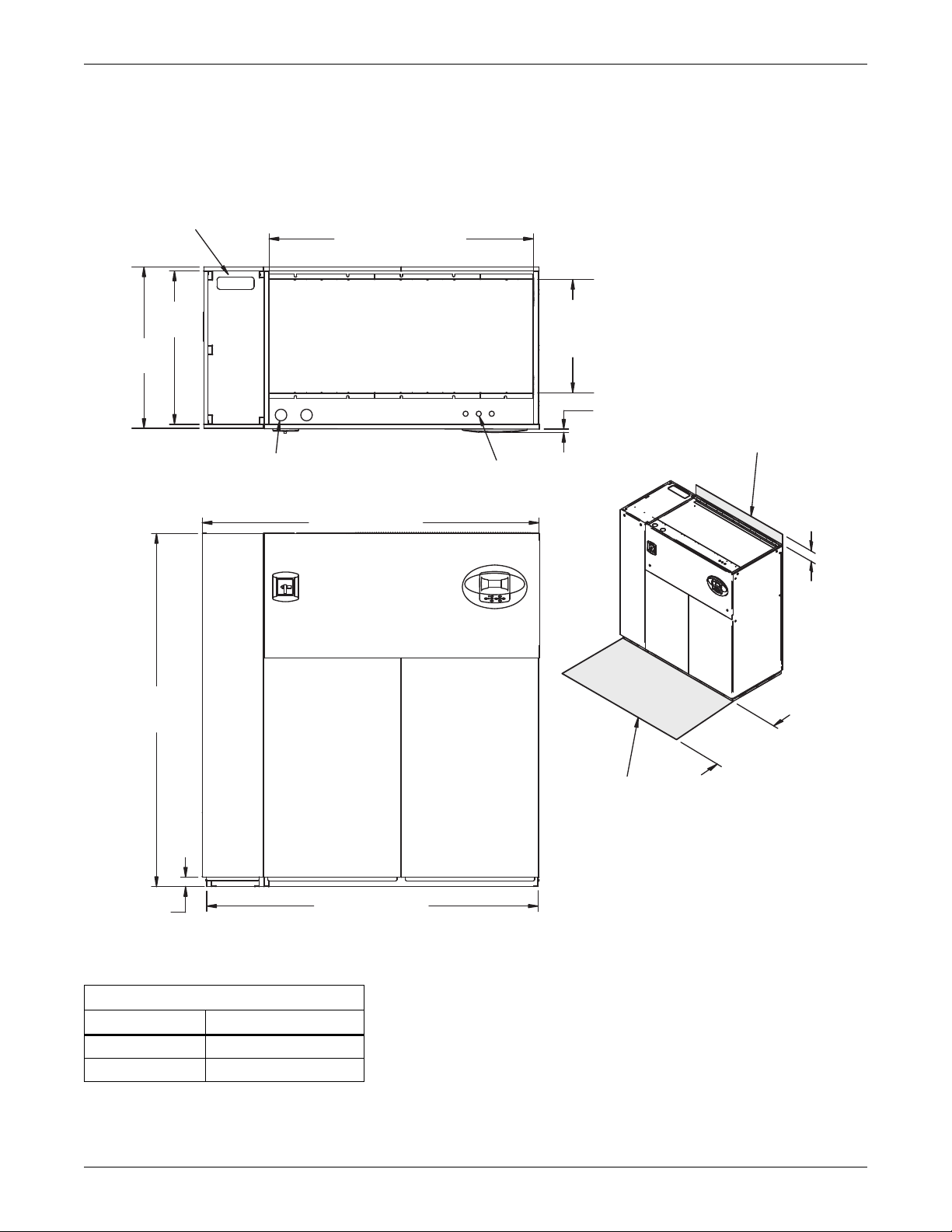
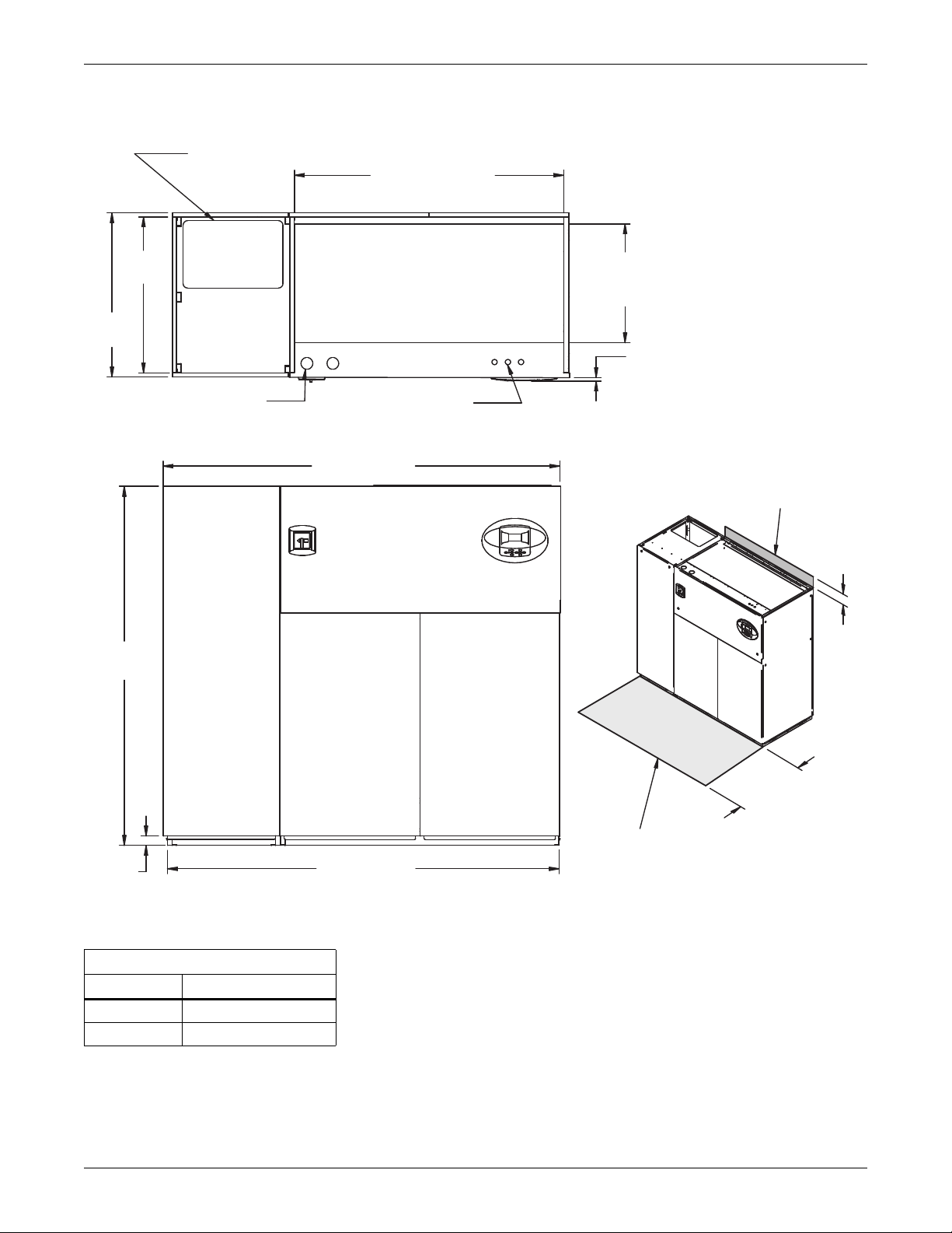
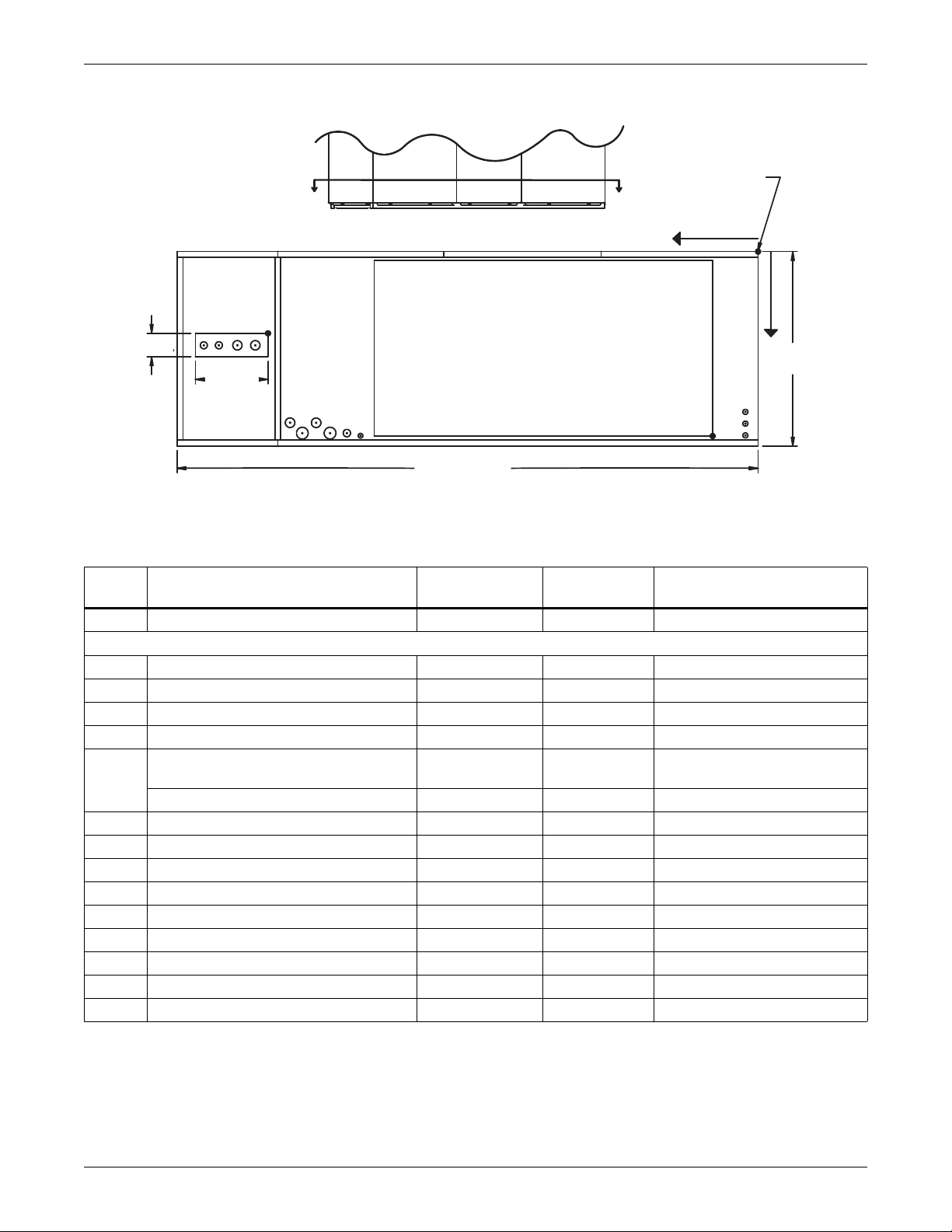
3.5 DIMENSIONS—LIEBERT DS 028-042, DOWNFLOW, AIR-COOLED MODELS
Secondary Refrigerant
Piping Entrance
DPN000796
Rev. 3
Filters are accessible
through top of unit only.
Downflow electrical
connections can be made
from top or bottom of unit.
Shaded area indicates a
recommended minimum
clearance for component
access.
TOP VIEW
Air Inlet Opening
Secondary Entrance
High-Volt Connection(s)
Secondary Entrance
Low-Volt Connections
Minimum required
for filter replacement
73" (1854mm)
72" (1829mm)
76"
(1930mm)
35"
(889mm)
56-7/8"
(1445mm)
Opening
Opening
3/4"
(19mm)
24-3/8"
(619mm)
34" (864mm)
33"
(838mm)
5"
(127mm)
Bezels
FRONT VIEW
2"
(51mm)
The following figures are general illustrations that show the dimensional layout for a Liebert DS unit.
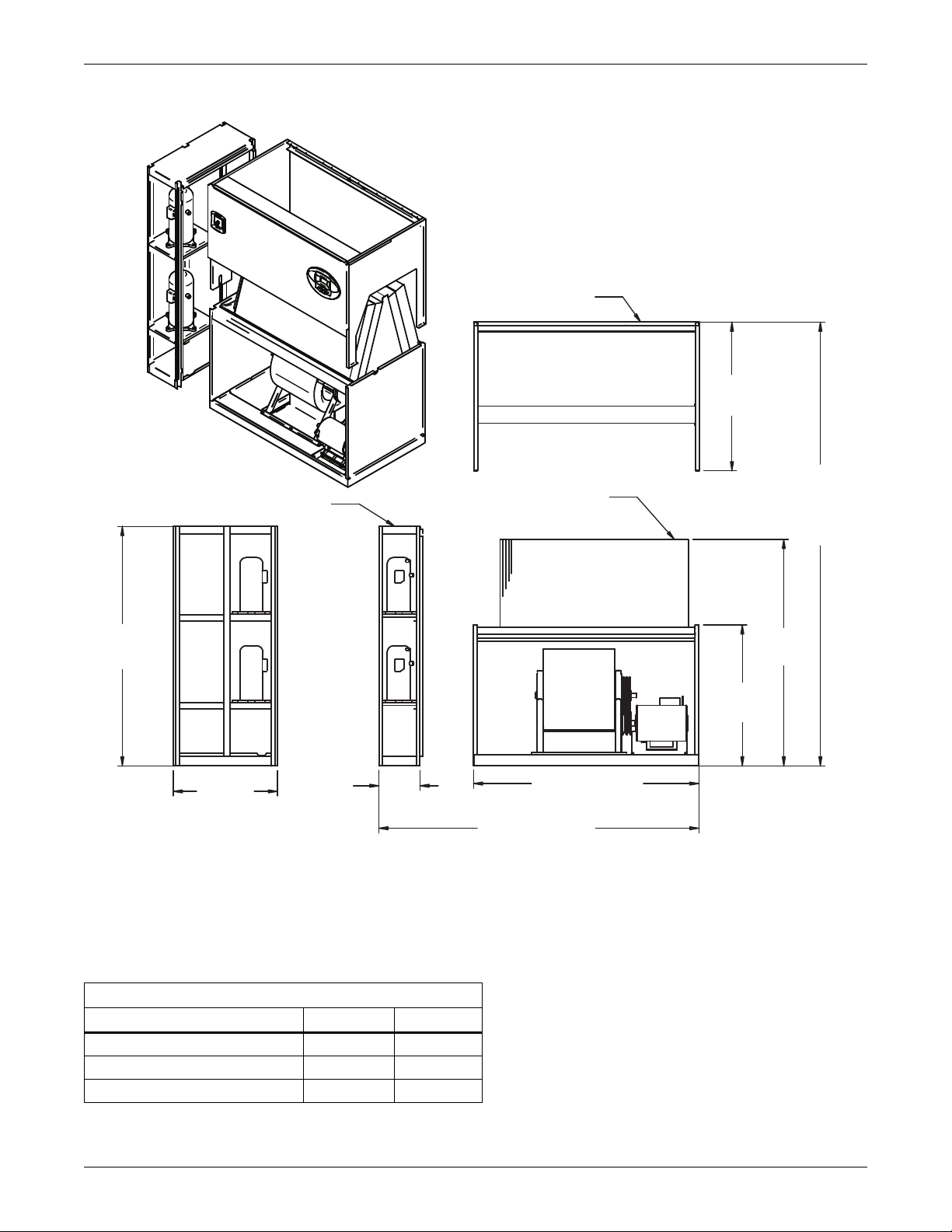
Figure 8 Dimensions—downflow, air-cooled, 28-42kW (8-12 ton), scroll or digital scroll compressors
with centrifugal fans
Air-Cooled Systems
Table 6 Weights—downflow, air-cooled, 28-42kW (8-12 ton), scroll/digital scroll compressors
Dry Weight, Approximate, lb. (kg)
Model Type Model Size: 028-042
Air-Cooled 1470 (668)
Dual-Cool 1620 (736)
Source: DPN000796, Rev. 3
Liebert® DS
™
16
Page 21
Air-Cooled Systems
Figure 9 Dimensions—downflow, air-cooled, 28-42kW (8-12 ton), front and/or rear discharge models
Minimum required
for filter replacement
Filters are accessible
only through top of unit.
5"
(127mm)
Secondary Refrigerant
Piping Entrance
(1445mm) Opening
56-7/8"
24" (610mm)
Required for Condenser
cleanout on Water/Glycol or
GLYCOOL/Dual Cool
3"
(77mm)
24-3/8"
(619mm)
Opening
3/4"
(19mm)
Bezels
Shaded area indicates a
recommended minimum
clearance for component access.
3"
(76mm)
(483mm)
19"
3-1/4"
(81mm)
33-3/8"
(848mm)
Air Outlet
Opening
REAR VIEW
33"
(838mm)
35"
(889mm)
Secondary Entrance
High-Voltage Connection(s)
76"
(1930mm)
2"
(51mm)
FRONT VIEW
AIR INLET OPENING
TOP VIEW
Secondary Entrance
Low-Voltage Connections
A
33-1/2"
(851mm)
19"
(483mm)
Air Outlet
Opening
3-1/4"
(83mm)
B
Customer Piping and Wiring Connections
1. For primary connection locations see standard submittals DPN000803, DPN000804 or DPN000900.
A floor stand at least 9" high is recommended if primary connections locations are to be used.
2. If no floor stand is used and unit is placed directly on the floor, then do the following:
a) Use secondary connection locations (shown on standard floor planning submittals).
b) Order a condensate pump.
c) Field pipe condensate and humidier line (if ordered) to secondary connection point in
compressor section.
d) Or order additional SFA's to relocate connection locations
34"
(864mm)
310697
Pg. 1, Rev. 0
Dry Weight, lb (kg) Approximate Dimensions, In. (mm)
Compressor Type Model
Semi-Hermetic
Scroll / Digital
Source: 310697, Pg. 1, Rev. 0
028-042 A B
Air-Cooled 1780 (809)
Dual Cool 1930 (877)
Air-Cooled 1470 (668)
Dual Cool 1620 (736)
86 (2184mm) 85 (2159)
73 (1854) 72" (1829)
17 Liebert® DS
™
Page 22
Air-Cooled Systems
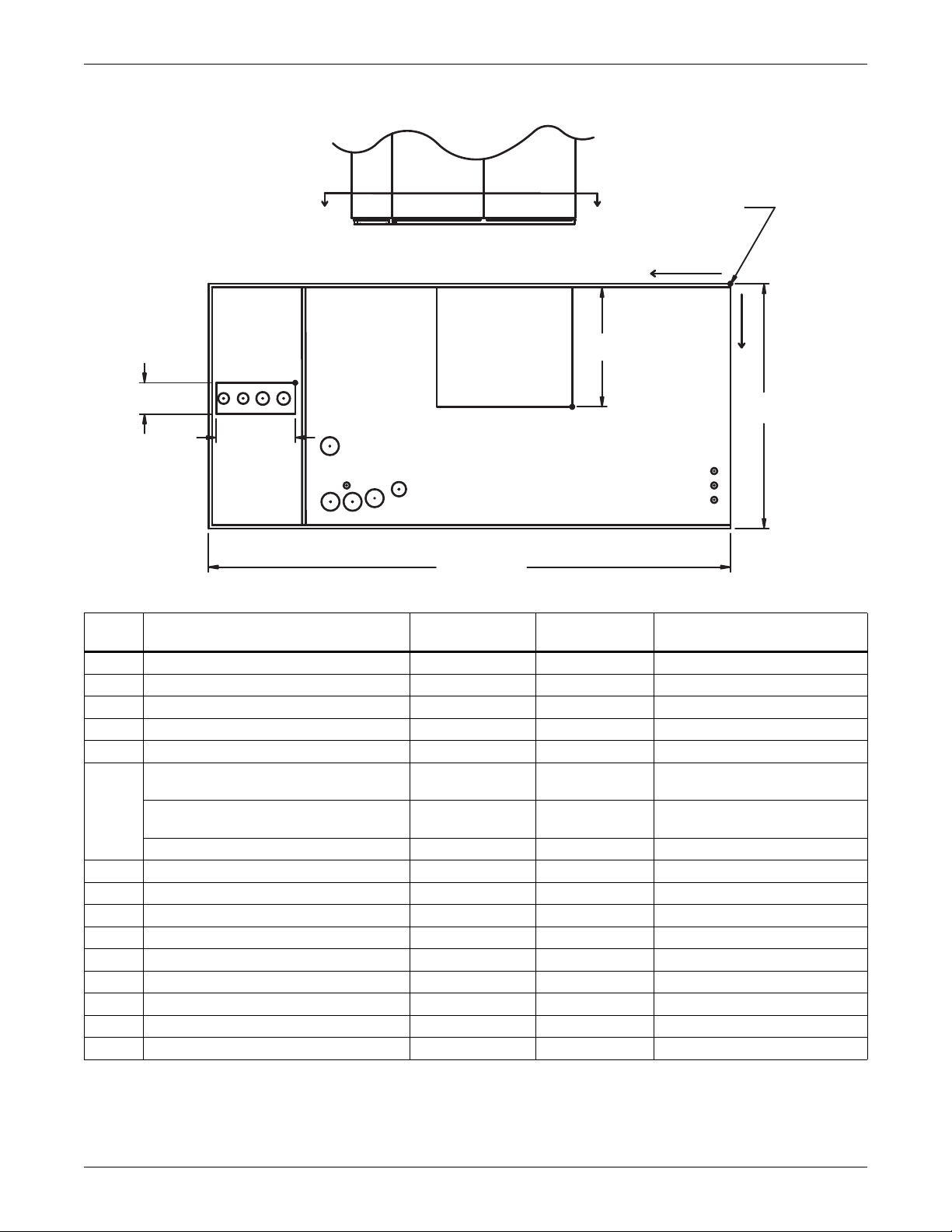
Figure 10 Primary connection locations—downflow, air-cooled, 28-42kW (8-12 ton), scroll or
digital scroll compressors with centrifugal fans
NOTE: Drawing not to scale.
Tolerance on
all piping dimensions
is ± 1/2" (13mm).
G1
L1
4" (102mm)
L2
11-3/16"
(284mm)
G2
A
FRONT VIEW
SECTION A-A
BLOWER
R
ECS
HUM
CD
E2
ECR
E1
OUTLET
16-1/16"
(408mm)
B
FRONT OF UNIT
73" (1854mm)
A
All dimensions from
rear corner of unit,
including panels
X
LV1
LV2
LV3
O
Y
35"
(889mm)
DPN000804
Rev. 3
Table 7 Piping data—downflow, air-cooled, 28-42kW (8-12 ton), scroll/digital scroll
Point Description
in. (mm)
R Refrigerant Access 59-5/16 (1507) 14-3/4 (375) 11-3/16 x 4 (284 x 102)
L1 Liquid Line System 1 69-15/16 (1776) 16-13/16 (411) 1/2" Cu Sweat
L2 Liquid Line System 2 67-5/8 (1718) 16-13/16 (411) 1/2" Cu Sweat
G1 Hot Gas Discharge 1 65-1/2 (1664) 16-13/16 (411) 5/8" Cu Sweat
G2 Hot Gas Discharge 2 62-7/16 (1586) 16-13/16 (411) 5/8" Cu Sweat
X
CD
Condensate Drain
(infrared humidifier or no humidifier) *
Condensate Drain
(steam generating humidifier) *
46 (1168) 29-1/2 (749) 3/4" FPT
46 (1168) 29-1/2 (749) 1-1/4" FPT
W/ Optional Pump 46 (1168) 29-1/2 (749) 1/2" Cu Sweat
HUM Humidifier Supply Line 53-1/2 (1359) 29 (737) 1/4" Cu Sweat
ECS Econ-O-Coil Supply 54-7/8 (1394) 22-9/16 (573) 1-5/8" Cu Sweat
ECR Econ-O-Coil Return 49-3/8 (1254) 30-3/4 (781) 1-5/8" Cu Sweat
E1 Electrical Conn. (High Volt) 55-1/2 (1410) 31-1/4 (794) 2-1/2"
E2 Electrical Conn. (High Volt) 52-7/16 (1332) 31-1/4 (794) 2-1/2"
LV1 Electrical Conn. (Low Volt) 2-1/4 (57) 27 (686) 7/8"
LV2 Electrical Conn. (Low Volt) 2-1/4 (57) 29 (737) 7/8"
LV3 Electrical Conn. (Low Volt) 2-1/4 (57) 31 (787) 7/8"
B Blower Outlet 21-15/16 (557) 18-1/16 (459) 18-3/4 x 16-1/16 (476 x 408)
* Field pitch condensate drain line a minimum of 1/8" (3.2 mm) per foot (305 mm). All units contain a factory-installed condensate trap. Do
not trap external to the unit. Drain line may contain boiling water. Select appropriate drain system materials. The drain line must comply
with all local codes.
Piping dimensions shown are connection sizes; field piping sizes may be different depending on distance. Refer to user manual, SL-18825.
Source: DPN000804, Rev. 3
Y
in. (mm)
Connection Size / Opening
in. (mm)
Liebert® DS
™
18
Page 23
Air-Cooled Systems
59" (1499mm)
DPN000802
Rev. 2
33"
(838mm)
13"
(330mm)
76"
(1930mm)
72" (1829mm)
Assembled Length
76"
(1930mm)
Assembled
Height
60-3/16"
(1529mm)
37"
(940mm)
39"
(991mm)
Compressor Assembly
Filter & Electric
Box Assembly
Blower & Coil
Assembly
NOTES: Drawing views are simplified with panels removed to show overall dimensions.
See disassembly and handling instructions in installation manual.
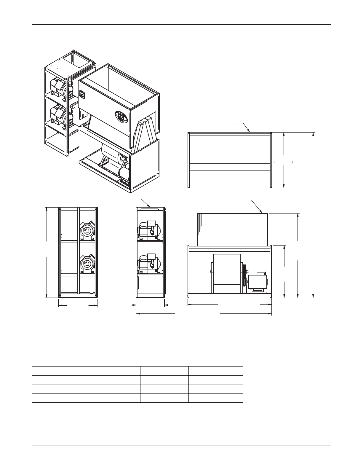
Figure 11 Disassembly dimensions—downflow, air-cooled, 28-42kW (8-12 ton), scroll or digital scroll
compressors with centrifugal fans
Table 8 Component weights—downflow, air-cooled, 28-42kW (8-12 ton), scroll or digital scroll
compressors
Dry Weight, Approximate, lb. (kg)
Component
Compressor Assembly 490 (223) 490 (223)
Filter and Electric Box Assembly 210 (96) 210 (96)
Blower and Coil Assembly 770 (350) 920 (418)
Source: DPN000802, Rev. 2
Air-Cooled Dual-Cool
19 Liebert® DS
™
Page 24
DPN000795
Rev. 4
Filters are accessible
through top of unit only.
Downflow electrical
connections can be made
from top or bottom of unit.
Shaded area indicates a
recommended minimum
clearance for component
access.
TOP VIEW
FRONT VIEW
Air Inlet Opening
Secondary Entrance
High Volt Connection(s)
Secondary Refrigerant
Piping Entrance
Secondary Entrance
Low Volt Connections
Minimum required
for filter replacement
86" (2184mm)
85" (2159mm)2"
(51mm)
76"
(1930mm)
35"
(889mm)
56-7/8"
(1445mm)
Opening
3/4"
(19mm)
Opening
34"
(864mm)
33"
(838mm)
5"
(127mm)
Bezels
24-3/8"
(619mm)
Air-Cooled Systems
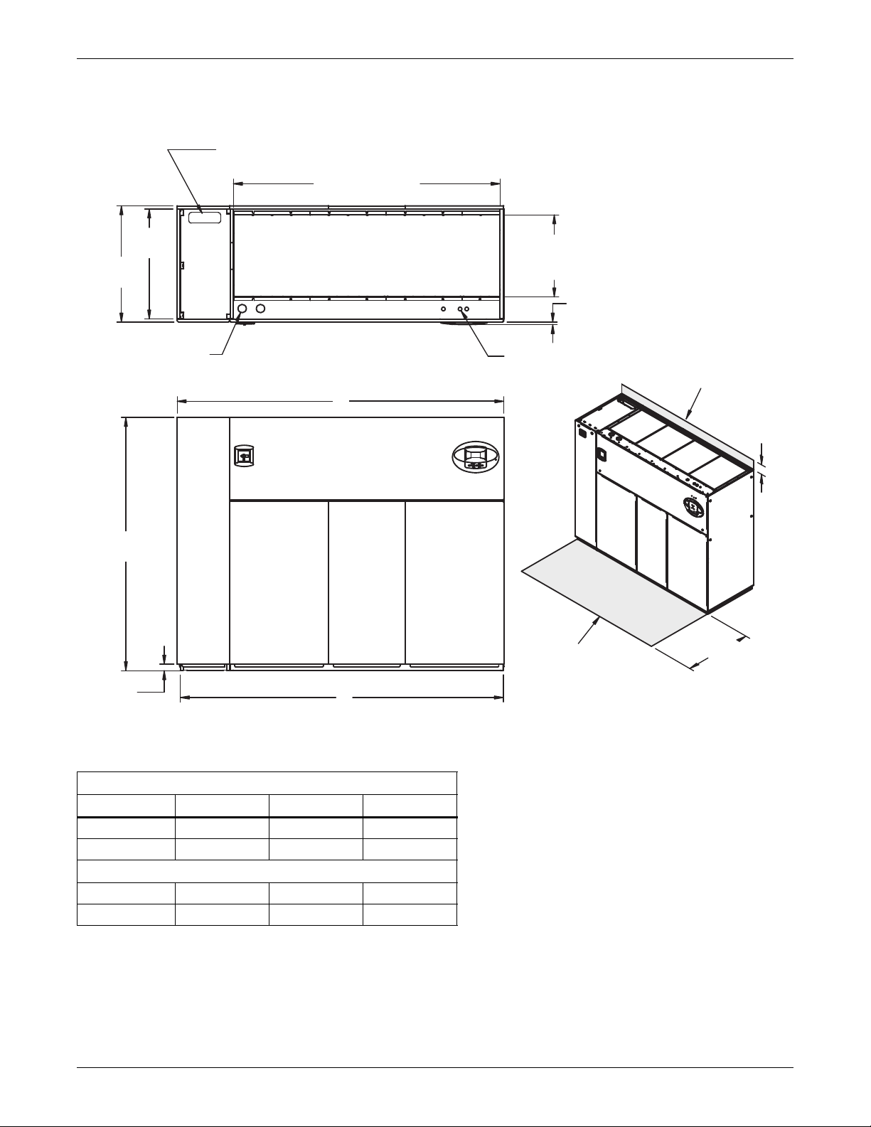
Figure 12 Dimensions—downflow, air-cooled, 28-42kW (8-12 ton), semi-hermetic compressors with
centrifugal fans
Table 9 Weights—downflow, air-cooled, 28-42kW (8-12 ton), semi-hermetic compressors
Dry Weight, Approximate, lb. (kg)
Model Type Model Size: 028-042
Air-Cooled 1780 (809)
Dual-Cool 1930 (877)
Source: DPN000795, Rev. 4
Liebert® DS
™
20
Page 25
Air-Cooled Systems
L1
L2
G1
G2
R
E1
E2
HUM
B
O
X
Y
A
A
ECS
ECR
CD
FRONT VIEW
LV1
NOTE: Drawing not to scale.
Tolerance on
all piping dimensions
is ± 1/2" (13mm).
4" (102mm)
BLOWER
OUTLET
All dimensions from
rear corner of unit
including panels
16-1/16"
(408mm)
35"
(889mm)
LV2
LV3
SECTION A-A
FRONT OF UNIT
16-7/16"
(418mm)
86"
(2184mm)
DPN000803
Rev. 4
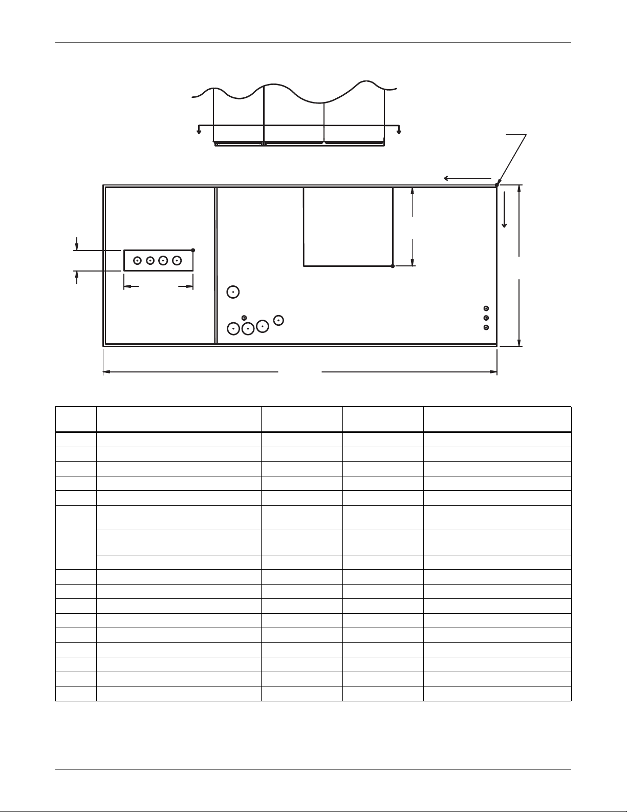
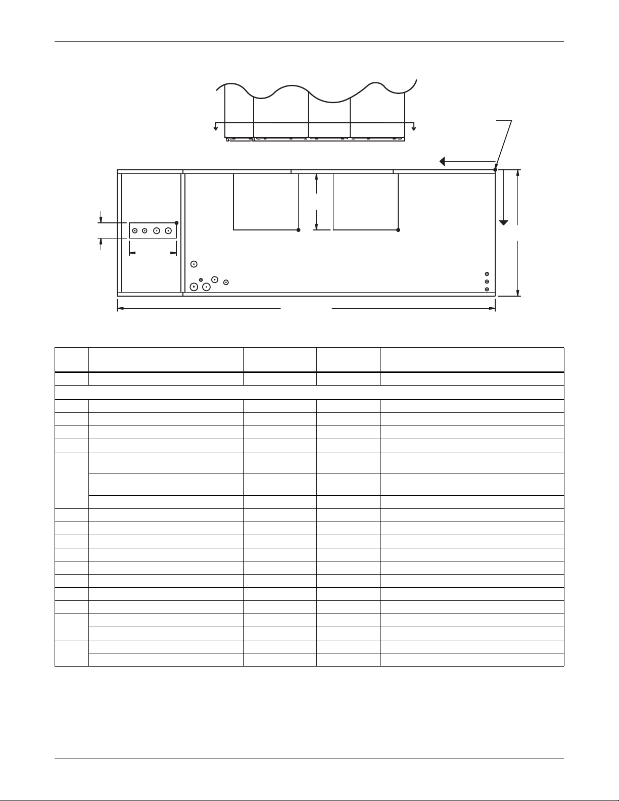
Figure 13 Primary connection locations—downflow, air-cooled, 28-42kW (8-12 ton), semi-hermetic
compressors with centrifugal fans
Table 10 Piping data—downflow, air-cooled, 28-42kW (8-12 ton), semi-hermetic compressors
Point Description
R Refrigerant Access 63 (1600) 13-13/16 (351) 16-7/16 x 4 (418 x 102)
L1 Liquid Line System 1 79-3/16 (2011) 16-3/4 (425) 1/2" Cu Sweat
L2 Liquid Line System 2 76-1/2 (1943) 16-3/4 (425) 1/2" Cu Sweat
G1 Hot Gas Discharge 1 73-7/8 (1876) 16-3/4 (425) 5/8" Cu Sweat
G2 Hot Gas Discharge 2 70-1/8 (1780) 16-3/4 (425) 5/8" Cu Sweat
CD
HUM Humidifier Supply Line 53-1/2 (1359) 29 (737) 1/4" Cu Sweat
ECS Econ-O-Coil Supply 54-7/8 (1394) 22-9/16 (573) 1-5/8" Cu Sweat
ECR Econ-O-Coil Return 49-3/8 (1254) 30-3/4 (781) 1-5/8" Cu Sweat
E1 Electrical Conn. (High Volt) 55-1/2 (1410) 31-1/4 (794) 2-1/2"
E2 Electrical Conn. (High Volt) 52-7/16 (1332) 31-1/4 (794) 2-1/2"
LV1 Electrical Conn. (Low Volt) 2-1/4 (57) 27 (686) 7/8"
LV2 Electrical Conn. (Low Volt) 2-1/4 (57) 29 (737) 7/8"
LV3 Electrical Conn. (Low Volt) 2-1/4 (57) 31 (787) 7/8"
B Blower Outlet 21-15/16 (558) 18-1/16 (459) 18-3/4 x 16-1/16 (476 x 408)
* Field pitch condensate drain line a minimum of 1/8" (3.2 mm) per foot (305 mm). All units contain a factory-installed condensate trap. Do
not trap external to the unit. Drain line may contain boiling water. Select appropriate drain system materials. The drain line must comply
with all local codes.
Piping dimensions shown are connection sizes; field piping sizes may be different depending on distance. Refer to user manual, SL-18825.
Source: DPN000803, Rev. 4
Condensate Drain
(infrared humidifier or no humidifier)*
Condensate Drain
(steam generating humidifier)*
W/ Optional Pump 46 (1168) 29-1/2 (749) 1/2" Cu Sweat
X
in. (mm)
Y
in. (mm)
Connection Size / Opening
in. (mm)
46 (1168) 29-1/2 (749) 3/4" FPT
46 (1168) 29-1/2 (749) 1-1/4" FPT
21 Liebert® DS
™
Page 26
Air-Cooled Systems
39"
991mm
59" (1499mm)
DPN000801
Rev. 2
33"
(838mm)
76"
(1930mm)
26"
(660mm)
85" (2159mm)
Assembled Length
76"
(1930mm)
Assembled
Height
60-3/16"
(1529mm)
37"
(940mm)
39"
(991mm)
Compressor Assembly
Filter & Electric
Box Assembly
Blower & Coil
Assembly
NOTES: Drawing views are simplified with panels removed to show overall dimensions.
See disassembly and handling instructions in installation manual.
Figure 14 Disassembly dimensions—downflow, air-cooled, 28-42kW (8-12 ton), semi-hermetic
compressors with centrifugal fans
Table 11 Component weights—downflow, air-cooled, 28-42kW (8-12 ton), semi-hermetic compressors
Dry Weight, Approximate, Including Panels, lb (kg)
Component
Compressor Assembly 800 (364) 800 (364)
Filter and Electric Box Assembly 210 (96) 210 (96)
Blower and Coil Assembly 770 (350) 920 (418)
Source: DPN000801, Rev. 2
Air-Cooled Dual-Cooled
Liebert® DS
™
22
Page 27
Air-Cooled Systems
33"
(838mm)
35"
(889mm)
A
76"
(1930mm)
2"
(51mm)
B
34"
(864mm)
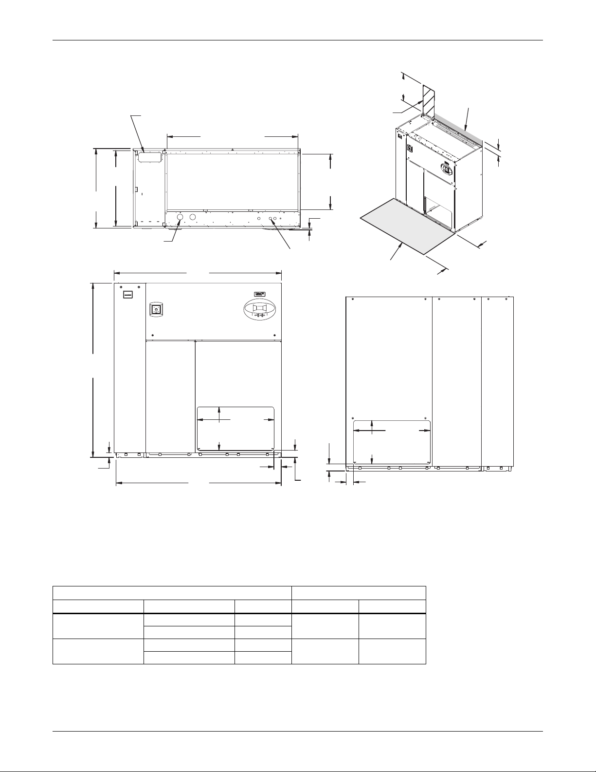
Shaded area indicates a
recommended minimum
clearance for component access.
5"
(127mm)
3/4"
(19mm)
Bezels
24-5/8"
(619mm)
Opening
80"
(2032mm)
Second Refrigerant
Piping Entrance
AIR INLET OPENING
Opening
Secondary Entrance
Low-Volt Connections
Minimum required
for filter replacement
Secondary Entrance
High-Volt Connection(s)
TOP VIEW
FRONT VIEW
Notes: Filters are accessible
through top of unit only.
Downflow electrical
connections can be made
from top or bottom of unit.
DPN000925
Rev. 2
Digital scroll compressors
not available on DS 077.
3.6 DIMENSIONS—LIEBERT DS 053-077, DOWNFLOW, AIR-COOLED MODELS
Figure 15 Dimensions—downflow, air-cooled, 53-77kW (15-22 ton), scroll or digital scroll compressors
with centrifugal fans
Table 12 Weights—downflow, air-cooled, 53-77kW (15-22 ton), scroll or digital scroll compressors
Model No. DS 053 DS 070 DS 077 *
Air Cooled 1920 (871) 1970 (894) 2020 (916)
Dual Cool 2100 (953) 2150 (975) 2200 (998)
Air Cooled “A” 98 (2489) 98 (2489) 98 (2489)
Air Cooled “B” 97 (2464) 97 (2464) 97 (2464)
* Digital scroll compressors not available on DS 077
Source: DPN000925, Rev. 2
Dry Weight, lb (kg) Approximate
Dimensions, in (mm)
23 Liebert® DS
™
Page 28
Air-Cooled Systems
A
A
L1
L2
G1
G2
R
ECS
ECR
E1
E2
HUM
CD
B1
O
X
Y
B2
FRONT VIEW
LV1
NOTE: Drawing not to scale.
Tolerance on
all piping dimensions
is ± 1/2" (13mm).
4"
(102mm)
BLOWER
OUTLET
All dimensions from
rear corner of unit
including panels
16-1/16"
(408mm)
35"
(889mm)
LV2
LV3
SECTION A-A
FRONT OF UNIT
12-3/16"
(310mm)
98" (2489mm)
BLOWER
OUTLET
DPN000929
Rev. 4
Digital scroll compressors
not available on DS 077.
Figure 16 Primary connection locations—downflow, air-cooled, 53-77kW (15-22 ton), scroll or digital
scroll compressors with centrifugal fans
Table 13 Piping data—downflow, air-cooled, 53-77kW (15-22 ton), scroll or digital scroll compressors ***
Point Description
R Refrigerant Access 81-3/4 (2076) 14-3/4 (374) 12-3/16 x 4 (310 x 102)
L1 Liquid Line System 1 94-11/16 (2405) 16-3/4 (425) 1/2" / 5/8" Cu Sweat
L2 Liquid Line System 2 91-7/8 (2334) 16-3/4 (425) 1/2" / 5/8" Cu Sweat
G1 Hot Gas Discharge 1 88-3/4 (2254) 16-3/8 (416) 7/8" / 1-1/8" Cu Sweat
G2 Hot Gas Discharge 2 85-9/16 (2173) 16-3/8 (416) 7/8" / 1-1/8" Cu Sweat
CD
HUM Humidifier Supply Line 76-1/2 (1943) 29 (736) 1/4" Cu Sweat
ECS** Econ-O-Coil Supply 78-5/8 (1997) 22-1/4 (565) 2-1/8" Cu Sweat
ECR** Econ-O-Coil Return 72 (1829) 29 (737) 2-1/8" Cu Sweat
E1 Electrical Conn. (High Volt) 78-1/2 (1994) 31-1/8 (790) 2-1/2"
E2 Electrical Conn. (High Volt) 75-3/8 (1915) 31-1/8 (790) 2-1/2"
LV1 Electrical Conn. (Low Volt) 1-7/8 (48) 28-1/2 (724) 7/8"
LV2 Electrical Conn. (Low Volt) 1-7/8 (48) 30-1/4 (768) 7/8"
LV3 Electrical Conn. (Low Volt) 1-7/8 (48) 32 (813) 7/8"
B1
B2
* Field pitch condensate drain line a minimum of 1/8" (3.2 mm) per foot (305 mm). All units contain a factory-installed condensate trap. Do
** Supplied on Dual-Cooling systems only (four-pipe system)
*** Digital scroll compressors not available on DS 077.
Piping dimensions shown are connection sizes; field piping sizes may be different depending on distance. Refer to user manual, SL-18825.
Source: DPN000929, Rev 4
Liebert® DS
X
in. (mm)
Y
in. (mm)
Connection Size / Opening
in. (mm)
53kW (15 ton) / 70& 77kW (20 & 22 ton)
Condensate Drain
(infrared humidifier or no humidifier)*
Condensate Drain
(steam generating humidifier)*
67-11/16 (1719) 30-1/2 (775) 3/4" FPT
67-11/16 (1719) 30-1/2 (775) 1-1/4" FPT
W/ Optional Pump 67-11/16 (1719) 30-1/2 (775) 1/2" Cu Sweat
Blower Outlet (15 x 15) 23-1/8 (587) 18-1/16 (459) 18-3/4 x 16-1/16 (476 x 408)
Blower Outlet (15 x 11) 27-3/4 (705) 18-1/16 (459) 14-3/4 x 16-1/16 (375 x 408)
Blower Outlet (15 x 15) 50-3/8 (1280) 18-1/16 (459) 18-3/4 x 16-1/16 (476 x 408)
Blower Outlet (15 x 11) 54-3/8 (1381) 18-1/16 (459) 14-3/4 x 16-1/16 (375 x 408)
not trap external to the unit. Drain line may contain boiling water. Select appropriate drain system materials. The drain line must comply
with all local codes.
™
24
Page 29
Air-Cooled Systems
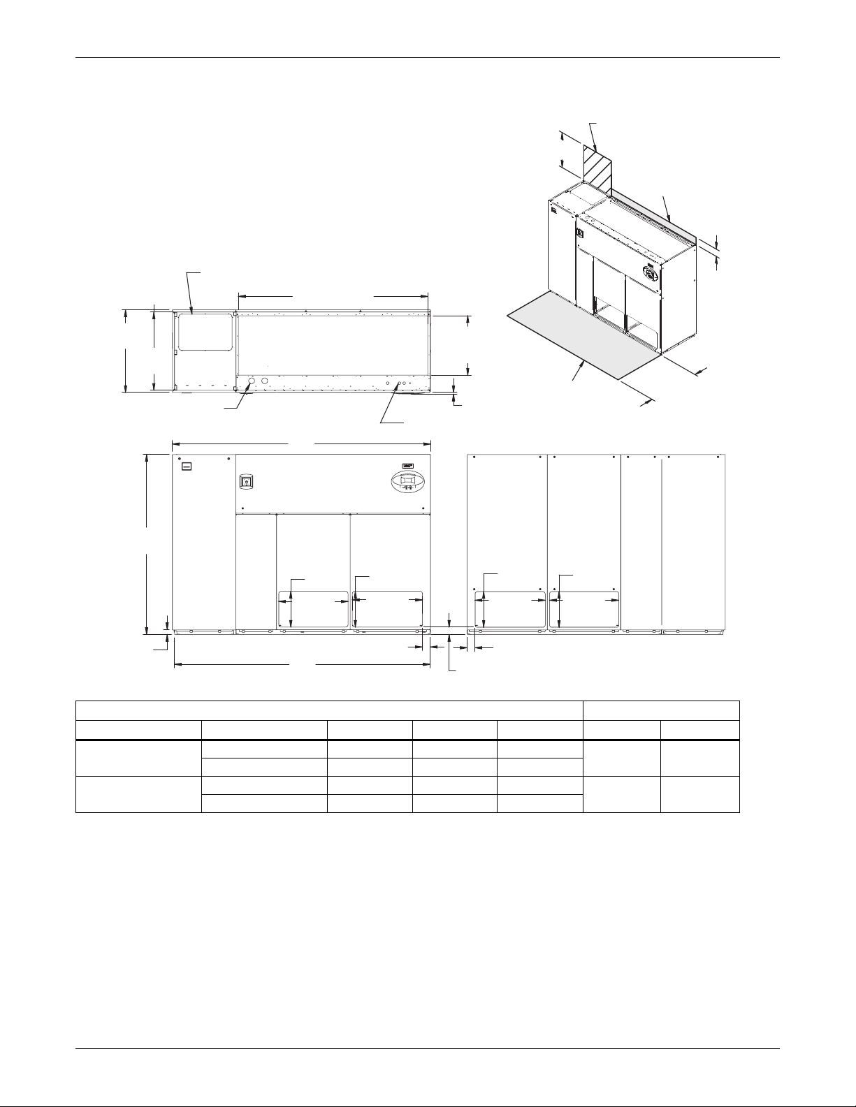
Figure 17 Dimensions—downflow, air-cooled, 53-77kW (15-22 ton), front and/or rear discharge models
with EC fans
Required for Condenser
cleanout on Water/Glycol or
Customer Piping and Wiring Connections
1. For primary connection locations see standard submittals DPN000928,
DPN000929 or DPN000933.
A floor stand at least 9" high is recommended if primary connections locations are to be used.
2. If no floor stand is used and unit is placed directly on the floor, then do the following:
a) Use secondary connection locations (shown on standard floor planning submittals).
b) Order a condensate pump.
c) Field pipe condensate and humidier line (if ordered) to secondary connection point in
compressor section.
d) Or order additional SFA's to relocate connection locations
Secondary Refrigerant
Piping Entrance
80" (2032mm)
Opening
24" (610mm)
GLYCOOL/Dual Cool
Minimum required
for filter replacement
Filters are accessible
only through top of unit.
5"
(127mm)
35"
(889mm)
33"
(838mm)
Secondary Entrance
High-Voltage Connection(s)
AIR INLET OPENING
TOP VIEW
A
76"
(1930mm)
15-1/8"
(384mm)
29-1/4"
(743mm)
Air Outlet
Opening
2"
(51mm)
FRONT VIEW
B
Dry Weight, lb (kg) Approximate Dimensions, in. (mm)
Compressor Type
Semi-Hermetic
Scroll / Digital
* Digital scroll compressors not available on 077 models
Source: 310697, Pg. 2, Rev. 0
Model 53 70 77 * A B
Air-Cooled 2350 (1069) 2400 (1091) 2450 (1114)
Dual Cool 2530 (1150 2580 (1173) 2630 (1196)
Air-Cooled 1920 (873) 1970 (896) 2020 (919)
Dual Cool 2100 (955) 2150 (978) 2200 (1000)
15-1/8"
(384mm)
29-5/8"
(752mm)
3-1/4"
(83mm)
25-5/8"
(619mm)
Opening
3/4"
Secondary Entrance
Low-Voltage Connections
Air Outlet
Opening
(19mm)
3-1/8"
(79mm)
Shaded area indicates a
recommended minimum
clearance for component access.
15-1/8"
(384mm)
29-5/8"
(752mm)
3-1/4"
(83mm)
Air Outlet
Opening
15-1/8"
(384mm)
29-1/4"
(743mm)
Air Outlet
Opening
REAR VIEW
109 (2769) 108 (2743)
34"
(864mm)
310697
Pg. 2, Rev. 0
98 (2489) 97 (2464)
25 Liebert® DS
™
Page 30
Air-Cooled Systems
12-3/16"
(310mm)
FRONT OF UNIT
FRONT VIEW
DPN002182
Rev. 1
SECTION A-A
NOTE: Drawing not to scale.
Tolerance on
all piping dimensions
is ± 1/2" (13mm).
ECS
ECR
E1
E2
CD
R
LV1
LV2
LV3
X
AA
Y
O
All dimensions from
rear corner of unit
including panels
35"
(889mm)
BLOWER
OUTLET
HUM
L1 L2 G1
G2
B1
4" (102mm)
98" (2489mm)
Digital scroll compressors not
available on 077 models.
Figure 18 Primary connection locations—downflow air-cooled 53-77kW (15-22 ton), scroll or digital
scroll compressors with EC fans, front, rear or bottom discharge
Table 14 Piping details—downflow air-cooled 53-77kW (15-22 ton) with EC fans, scroll or digital scroll
Point Description
R Refrigerant Access 81-3/4 (2076) 14-3/4 (374) 12-3/16x4 (310x102)
L1 Liquid Line System 1 94-11/16 (2405) 16-3/4 (425) 1/2 / 5/8 Cu Sweat
L2 Liquid Line System 2 91-7/8 (2334) 16-3/4 (425) 1/2 / 5/8 Cu Sweat
G1 Hot Gas Discharge 1 88-3/4 (2254) 16-3/8 (416) 7/8 / 1-1/8 Cu Sweat
G2 Hot Gas Discharge 2 85-9/16 (2173) 16-3/8 (416) 7/8 / 1-1/8 Cu Sweat
CD
HUM Humidifier Supply Line 76-1/2 (1943) 29 (736) 1/4 Cu Sweat
ECS** Econ-O-Coil Supply (DS Only) 78-5/8 (1997) 22-1/4 (565) 2-1/8 Cu Sweat
ECR** Econ-O-Coil Return (DS Only) 73-15/16 (1862) 26-9/16 (675) 2-1/8 Cu Sweat
E1 Electrical Conn. (High Volt) 78-1/2 (1994) 31-1/8 (790) 2-1/2
E2 Electrical Conn. (High Volt) 75-3/8 (1915) 31-1/8 (790) 2-1/2
LV1 Electrical Conn. (Low Volt) 2 (51) 29 (737) 7/8
LV2 Electrical Conn. (Low Volt) 2 (51) 30-7/8 (784) 7/8
LV3 Electrical Conn. (Low Volt) 2 (51) 32 (813) 7/8
B1 Blower Outlet 4-1/2 (114) 33 (838) 58-3/8x30 (1483x762)
* Field pitch condensate drain line a minimum of 1/8" (3.2 mm) per foot (305 mm). All units contain a factory-installed condensate trap. Do
not trap external to the unit. Drain line may contain boiling water. Select appropriate drain system materials. The drain line must comply
with all local codes.
** Supplied on Dual-Cooling systems only (four-pipe system)
*** Digital scroll compressors not available on DS 077
Piping dimensions shown are connection sizes; field piping sizes may be different depending on distance. Refer to user manual, SL-18825.
Source: DPN002182, Rev. 1
Liebert® DS
compressors ***
Condensate Drain
(Infrared Humidifier or No Humidifier)*
W/ Optional Pump 68-3/8 (1737) 31-3/8 (797) 1/2 Cu Sweat
™
X
in. (mm)
Y
in. (mm)
Connection Size / Opening
53kW (15 ton)/ 70 & 77kW (20 & 22 ton)
68-3/8 (1737) 31-3/8 (797) 3/4 FPT
26
in. (mm)
Page 31

Air-Cooled Systems
Digital scroll compressors
not available on DS 077.
Figure 19 Disassembly dimensions—downflow, air-cooled, 53-77kW (15-22 ton), scroll or digital scroll
compressors
Filter & Electric
Box Assembly
Forward curved
blowers shown.
DA units only
available with EC
blowers, optional
on DS units.
Compressor Assembly
Blower & Coil
Assembly
76"
(1930mm)
33"
(838mm)
DS053-DS077 =
15" (381mm)
DA080,DA085 =
17" (432mm)
Assembled Length
97" (2464mm)
82" (2083mm)
NOTES: Drawing views are simplified with panels removed to show overall dimensions.
See disassembly and handling instructions in installation manual.
39"
(991mm)
76"
(1930mm)
Assembled
Height
59-7/16"
(1509mm)
37"
(940mm)
DPN000927
Rev. 4
Table 15 Component weights—downflow, air-cooled, 53-77kW (15-22 ton), scroll or digital scroll
compressors *
Dry Weight, Approximate, Including Panels, lb (kg)
Component
Compressor Assembly 540 (246) 540 (246)
Filter and Electric Box Assembly 250 (114) 250 (114)
Blower and Coil Assembly 1230 (560) 1410 (641)
* Digital scroll compressors not available on DS 077
Source: DPN00927, Rev. 4
Air-Cooled Dual-Cool
27 Liebert® DS
™
Page 32

Air-Cooled Systems
33"
(838mm)
35"
(889mm)
109" (2769mm)
76"
(1930mm)
2"
(51mm)
108" (2743mm)
34"
(864mm)
Shaded area indicates a
recommended minimum
clearance be provided for
component access.
5"
(125mm)
3/4"
(19mm)
24-5/8"
(625mm)
Opening
80"
(2032mm)
Second Refrigerant
Piping Entrance
AIR INLET OPENING
Opening
Bezels
Secondary Entrance
Low-Volt Connections
Minimum required
for filter replacement
Secondary Entrance
High-Volt Connection(s)
TOP VIEW
FRONT VIEW
Notes: Filters are accessible
through top of unit only.
Downflow electrical
connections can be made
from top or bottom of unit.
DPN000924
Rev. 3
Figure 20 Dimensions—downflow, air-cooled, 53-77kW (15-22 ton) with centrifugal fans, semi-hermetic
compressors with centrifugal fans
Table 16 Weights—downflow, air-cooled, 53-77kW (15-22 ton), semi-hermetic compressors
Model Type
Air-Cooled 2350 (1069) 2400 (1091) 2450 (1114)
Dual-Cool 2530 (1150) 2580 (1173) 2630 (1196)
Source: DPN000924, Rev. 3
Dry Weight, Approximate, lb. (kg)
Model Size
053 070 077
Liebert® DS
™
28
Page 33

Air-Cooled Systems
L1
L2
G1
G2
R
B1
O
X
Y
B2
ECS
ECR
E1
E2
HUM
CD
FRONT VIEW
LV1
NOTE: Drawing not to scale.
Tolerance on
all piping dimensions
is ± 1/2" (13mm).
BLOWER
OUTLET
All dimensions from
rear corner of unit
including panels
LV2
LV3
SECTION A-A
FRONT OF UNIT
AA
BLOWER
OUTLET
16-1/16"
(408mm)
16-7/16"
(418mm)
4" (102mm)
109" (2769mm)
35"
(889mm)
DPN000928
Rev. 4
Figure 21 Primary connection locations—downflow, air-cooled, 53-77kW (15-22 ton), semi-hermetic
compressors with centrifugal fans
Table 17 Piping data—downflow, air-cooled, 53-77kW (15-22 ton), semi-hermetic compressors
Point Description
R Refrigerant Access 82-3/4 (2102) 13-7/8 (352) 16-7/16 x 4 (418 x 102)
L1 Liquid Line System 1 97 (2464) 16-7/8 (428) 1/2" / 5/8" Cu Sweat
L2 Liquid Line System 2 93-5/16 (2370) 16-7/8 (428) 1/2" / 5/8" Cu Sweat
G1 Hot Gas Discharge 1 90-5/8 (2302) 16-5/8 (422) 7/8" / 1-1/8" Cu Sweat
G2 Hot Gas Discharge 2 88 (2235) 16-5/8 (422) 7/8" / 1-1/8" Cu Sweat
CD
HUM Humidifier Supply Line 76-1/2 (1943) 29 (736) 1/4" Cu Sweat
ECS** Econ-O-Coil Supply 78-5/8 (1997) 22-1/4 (565) 2-1/8" Cu Sweat
ECR** Econ-O-Coil Return 72 (1829) 29 (737) 2-1/8" Cu Sweat
E1 Electrical Conn. (High Volt) 78-1/2 (1994) 31-1/8 (790) 2-1/2"
E2 Electrical Conn. (High Volt) 75-3/8 (1915) 31-1/8 (790) 2-1/2"
LV1 Electrical Conn. (Low Volt) 1-7/8 (48) 28-1/2 (724) 7/8"
LV2 Electrical Conn. (Low Volt) 1-7/8 (48) 30-1/4 (768) 7/8"
LV3 Electrical Conn. (Low Volt) 1-7/8 (48) 32 (813) 7/8"
B1
B2
* Field pitch condensate drain line a minimum of 1/8" (3.2 mm) per foot (305 mm). All units contain a factory-installed condensate trap. Do
not trap external to the unit. Drain line may contain boiling water. Select appropriate drain system materials. The drain line must comply
with all local codes.
** Supplied on Dual-Cooling Systems only (four-pipe system)
Piping dimensions shown are connection sizes; field piping sizes may be different depending on distance. Refer to user manual, SL-18825.
Source: DPN000928, Rev. 4
X
in. (mm)
Y
in. (mm)
Connection Size / Opening
in. (mm)
53kW (15 tons) / 70 & 77kW (20 & 22 tons)
Condensate Drain
(infrared humidifier or no humidifier) *
Condensate Drain
(steam generating humidifier)*
67-11/16 (1719) 30-1/2 (775) 3/4" FPT
67-11/16 (1719) 30-1/2 (775) 1-1/4" FPT
W/ Optional Pump 67-11/16 (1719) 30-1/2 (775) 1/2" Cu Sweat
Blower Outlet (15 x 15) 23-1/8 (587) 18-1/16 (459) 18-3/4 x 16-1/16 (476 x 408)
Blower Outlet (15 x 11) 27-3/4 (705) 18-1/16 (459) 14-3/4 x 16-1/16 (375 x 408)
Blower Outlet (15 x 15) 50-3/8 (1280) 18-1/16 (459) 18-3/4 x 16-1/16 (476 x 408)
Blower Outlet (15 x 11) 54-3/8 (1381) 18-1/16 (459) 14-3/4 x 16-1/16 (375 x 408)
29 Liebert® DS
™
Page 34

Air-Cooled Systems
16-7/16"
(418mm)
FRONT OF UNIT
FRONT VIEW
DPN002179
Rev. 0
SECTION A-A
NOTE: Drawing not to scale.
Tolerance on
all piping dimensions
is ± 1/2" (13mm).
ECS ECR
E1
CD
R
LV1
LV2
LV3
X
AA
Y
O
All dimensions from
rear corner of unit
including panels
35"
(889mm)
BLOWER
OUTLET
HUM
L1
L2 G1 G2
B1
4" (102mm)
109" (2769mm)
Figure 22 Primary connection locations—downflow, air-cooled 53-77kW (15-22 ton), semi-hermetic
compressors with EC fans, front, rear or bottom discharge
Table 18 Piping details—downflow, air-cooled 53-77kW (15-22 ton) with EC fans, semi-hermetic
Point Description
G1 Hot Gas Discharge 1 90-5/8 (2302) 16-5/8 (422) 7/8 / 1-1/8 Cu Sweat
G2 Hot Gas Discharge 2 88 (2235) 16-5/8 (422) 7/8 / 1-1/8 Cu Sweat
CD
HUM Humidifier Supply Line 76-1/2 (1943) 29 (736) 1/4 Cu Sweat
ECS** Econ-O-Coil Supply 78-5/8 (1997) 22-1/4 (565) 2-1/8 Cu Sweat
ECR** Econ-O-Coil Return 73-15/16 (1862) 26-9/16 (675) 2-1/8 Cu Sweat
E1 Electrical Conn. (High Volt) 78-1/2 (1994) 31-1/8 (790) 2-1/2
E2 Electrical Conn. (High Volt) 75-3/8 (1915) 31-1/8 (790) 2-1/2
LV1 Electrical Conn. (Low Volt) 2 (51) 29 (737) 7/8
LV2 Electrical Conn. (Low Volt) 2 (51) 30-7/8 (784) 7/8
LV3 Electrical Conn. (Low Volt) 2 (51) 32 (813) 7/8
B1 Blower Outlet 4-1/2 (114) 33 (838) 58-3/8 x 30 (1483x762)
* Field pitch condensate drain line a minimum of 1/8" (3.2 mm) per foot (305 mm). All units contain a factory-installed condensate trap. Do
** Supplied on Dual-Cooling systems only (four-pipe system)
Piping dimensions shown are connection sizes; field piping sizes may be different depending on distance. Refer to user manual, SL-18825.
Source: DPN002179, Rev. 0
Liebert® DS
compressors
X
in. (mm)
R Refrigerant Access 82-3/4 (2102) 13-7/8 (352) 16-7/16 x 4 (4181x102)
L1 Liquid Line System 1 97 (2464) 16-7/8 (428) 1/2 / 5/8 Cu Sweat
L2 Liquid Line System 2 93-5/16 (2370) 16-7/8 (428) 1/2 / 5/8 Cu Sweat
Condensate Drain
(Infrared Humidifier or No Humidifier)*
68-3/8 (1737) 31-3/8 (797) 3/4 FPT
W/ Optional Pump 68-3/8 (1737) 31-3/8 (797) 1/2 Cu Sweat
Y
in. (mm)
Connection Size / Opening
in. (mm)
53kW (15 ton) /70 & 77kw (20 & 22 ton)
not trap external to the unit. Drain line may contain boiling water. Select appropriate drain system materials. The drain line must comply
with all local codes.
™
30
Page 35

Air-Cooled Systems
Figure 23 Disassembly dimensions—downflow, air-cooled, 53-77kW (15-22 ton), semi-hermetic
compressors with centrifugal fans
Filter & Electric
Box Assembly
39"
(991mm)
Compressor Assembly
Blower & Coil
Assembly
76"
(1930mm)
Assembled
Height
76"
(1930mm)
59-7/16"
(1509mm)
37"
(940mm)
33"
(838mm)
26"
(660mm)
82" (2083mm)
108" (2743mm)
Assembled Length
NOTES: Drawing views are simplified with panels removed to show overall dimensions.
See disassembly and handling instructions in installation manual.
DPN000926
Rev. 4
Table 19 Component weights—downflow, air-cooled, 53-77kW (15-22 ton), semi-hermetic compressors
Dry Weight, Approximate, Including Panels, lb (kg)
Component
Compressor Assembly 970 (441) 970 (441)
Filter and Electric Box Assembly 250 (114) 250 (114)
Blower and Coil Assembly 1230 (560) 1410 (641)
Source: DPN000926, Rev. 4
Air-Cooled Dual-Cool
31 Liebert® DS
™
Page 36

Air-Cooled Systems
5"
(127mm)
Notes: Filters are accessible
through top of unit only.
Downflow electrical
connections can be made
from top or bottom of unit.
TOP VIEW
AIR INLET OPENING
Shaded area indicates a
recommended minimum
clearance be provided for
component access.
24-3/8"
(619mm)
Opening
3/4"
(19mm)
Bezels
Secondary Entrance
High-Volt Connection(s)
76"
(1930mm)
FRONT VIEW
DPN0001012
Rev. 4
34" (864mm)
131" (3327mm)
132" (3353mm)
35"
(889mm)
Secondary Refrigerant
Piping Entrance
Secondary Entrance
Low-Volt Connections
102-13/16"
(2611mm) Opening
33"
(838mm)
Minimum required
for filter replacement
Digital scroll
compressors not
available on DS 105.
3.7 DIMENSIONS—LIEBERT DS 105, DOWNFLOW, AIR-COOLED MODELS
Figure 24 Dimensions—downflow, air-cooled, 105kW (30 ton), standard scroll and semi-hermetic
compressors with centrifugal fans
Table 20 Weights—downflow, air-cooled, 105kW (30 ton), standard scroll and semi-hermetic
Compressor Type
Semi-Hermetic
Compressors
Scroll Compressors *
* Digital scroll compressors not available on DS 105
Source: DPN001012, Rev. 4
compressors
Cooling Type
Air-Cooled 3040 (1382)
Dual-Cool 3400 (1545)
Air-Cooled 2920 (1327)
Dual-Cool 3280 (1491)
Forward-Curved Fans
Weight, lb. (kg)
Liebert® DS
™
32
Page 37

Figure 25 Primary connection locations—downflow, air-cooled, 105kW (30 ton), standard scroll and
ECS
ECR
E1
E2
CD
B1
O
X
Y
A
A
B2
B3
HUM
R
L1 L2
G1 G2
FRONT VIEW
LV1
NOTE: Drawing not to scale.
Tolerance on
all piping dimensions
is ± 1/2" (13mm).
4" (102mm)
BLOWER
OUTLET
All dimensions from
rear corner of unit
including panels
35"
(889mm)
LV2
LV3
SECTION A-A
FRONT OF UNIT
16-7/16"
(418mm)
131" (3327mm)
BLOWER
OUTLET
BLOWER
OUTLET
15-11/16"
(398mm)
DPN001014
Rev. 3
Digital scroll compressors not
available on 105 models.
semi-hermetic compressors with centrifugal fans
Table 21 Piping data—downflow, air-cooled, 105kW (30 ton), standard scroll*** and semi-hermetic
compressors
Point Description
R Refrigerant Access 109 (2769) 15-3/4 (400) 16-7/16 x 4 (418 x 102)
L1 Liquid Line System 1 121-3/4 (3092) 16-3/4 (425) 5/8" Cu Sweat
L2 Liquid Line System 2 118-1/8 (3000) 16-3/4 (425) 5/8" Cu Sweat
G1 Hot Gas Discharge 1 118-1/4 (3004) 14-1/4 (362) 1-1/8" Cu Sweat
G2 Hot Gas Discharge 2 115-5/8 (2937) 14-1/4 (362) 1-1/8" Cu Sweat
Condensate Drain
(infrared humidifier or no humidifier)*
CD
HUM Humidifier Supply Line 102-3/4 (2610) 31-3/4 (806) 1/4" Cu Sweat
ECS** Econ-O-Coil Supply 101-7/8 (2588) 29 (737) 2-5/8" Cu Sweat
ECR** Econ-O-Coil Return 94-9/16 (2402) 29 (737) 2-5/8" Cu Sweat
E1 Electrical Conn. (High Volt) 98-1/8 (2492) 31-1/4 (794) 2-1/2"
E2 Electrical Conn. (High Volt) 91 (2311) 31-1/4 (794) 2-1/2"
LV1 Electrical Conn. (Low Volt) 2 (51) 28-1/4 (718) 7/8"
LV2 Electrical Conn. (Low Volt) 2 (51) 30-1/4 (768) 7/8"
LV3 Electrical Conn. (Low Volt) 2 (51) 32 (813) 7/8"
B1 Blower Outlet 27-7/8 (708) 18 (457) 14-1/2 x 15-11/16 (368 x 398)
B2 Blower Outlet 52-1/16 (1322) 18 (457) 14-1/2 x 15-11/16 (368 x 398)
B3 Blower Outlet 76-1/4 (1937) 18 (457) 14-1/2 x 15-11/16 (368 x 398)
* Field pitch condensate drain line a minimum of 1/8" (3.2 mm) per foot (305 mm). All units contain a factory-installed condensate trap. Do not
trap external to the unit. Drain line may contain boiling water. Select appropriate drain system materials. The drain line must comply with all
local codes.
** Supplied on
** Digital scroll compressors not available on DS 105
*
Piping dimensions shown are connection sizes; field piping sizes may be different depending on distance. Refer to user manual, SL-18825.
Source: DPN001014, Rev. 3
Condensate Drain
(steam generating humidifier)*
Dual-Cooling systems only (four-pipe system)
X
in. (mm)
Y
in. (mm)
Connection Size / Opening
83-13/16 (2129) 30 (762) 3/4" FPT
83-13/16 (2129) 30 (762) 1-1/4" FPT
W/ Optional Pump 83-13/16 (2129) 30 (762) 1/2" Cu Sweat
33 Liebert® DS
Air-Cooled Systems
in. (mm)
™
Page 38

Air-Cooled Systems
Customer Piping and Wiring Connections
1. For primary connection locations see standard submittals DPN001014 or DPN001015.
A floor stand at least 9" high is recommended if primary connections locations are to be used.
2. If no floor stand is used and unit is placed directly on the floor, then do the following:
a) Use secondary connection locations (shown on standard floor planning submittals).
b) Order a condensate pump.
c) Field pipe condensate and humidier line (if ordered) to secondary connection point in
compressor section.
d) Or order additional SFA's to relocate connection locations
Secondary Entrance
High-Voltage Connection(s)
Shaded area indicates a
recommended minimum
clearance for component access.
Secondary Refrigerant
Piping Entrance
Secondary Entrance
Low-Voltage Connections
TOP VIEW
FRONT VIEW
310697
Pg. 3, Rev. 0
Air Outlet
Opening
Air Outlet
Opening
Air Outlet
Opening
3/4"
(19mm)
25-5/8"
(649mm)
24-7/8"
(649mm)
28-1/4"
(718mm)
16-1/8"
(410mm)
16-1/8"
(410mm)
16-1/8"
(410mm)
24-3/8"
(619mm)
Opening
102-7/8" (2611mm)
Opening
132" (3353mm)
30-7/8"
(783mm)
57-1/2"
(1459mm)
131" (3326mm)
3/4"
(19mm)
33"
(838mm)
35"
(889mm)
5"
(127mm)
34"
(864mm)
Required for Condenser
cleanout on Water/Glycol or
GLYCOOL/Dual Cool
Downflow electrical
connections can be made
from top or bottom of unit
24" (610mm)
Minimum required
for filter replacement
Filters are accessible
only through top of unit.
AIR INLET OPENING
76"
(1930mm)
Figure 26 Dimensions—downflow, air-cooled, 105kW (30 ton), front discharge models with EC fans
Dry Weight, lb (kg) Approximate
Model 105
Air-Cooled
2774 (1258)
Dual Cool 3134 (1422)
Air-Cooled
2654 (1204)
Dual Cool 3014 (1367)
Compressor Type
Semi-Hermetic
Scroll
Digital scroll compressors not available on DS 105
Source: 310697, Pg. 3, Rev. 0
Liebert® DS
™
34
Page 39

Air-Cooled Systems
16-7/16"
(418mm)
FRONT OF UNIT
FRONT VIEW
DPN002154
Rev. 0
SECTION A-A
NOTE: Drawing not to scale.
Tolerance on
all piping dimensions
is ± 1/2" (13mm).
ECS
ECR
E1
E2
CD
LV1
LV2
LV3
X
Y
O
A
A
All dimensions from
rear corner of unit
including panels
35"
(889mm)
BLOWER
OUTLET
HUM
L1
L2
G1 G2
B1
R
4" (102mm)
132" (3353mm)
Digital scroll compressors
not available on 105
models.
Figure 27 Primary connection locations—downflow, air-cooled 105kW (30 ton), standard scroll and
semi-hermetic compressors with EC fans, front, rear or bottom discharge
Table 22 Piping data—downflow, air-cooled 105kW (30 ton) with EC fans, standard scroll*** and
Point Description
R Refrigerant Access 109 (2769) 15-3/4 (400) 16-7/16 x 4 (418 x 102)
L1 Liquid Line System 1 121-3/4 (3092) 16-3/4 (425) 5/8 Cu Sweat
L2 Liquid Line System 2 118-1/8 (3000) 16-3/4 (425) 5/8 Cu Sweat
G1 Hot Gas Discharge 1 118-1/4 (3004) 14-1/4 (362) 1-1/8 Cu Sweat
G2 Hot Gas Discharge 2 115-5/8 (2937) 14-1/4 (362) 1-1/8 Cu Sweat
CD
HUM Humidifier Supply Line 85-5/16 (2167) 32-1/2 (825) 1/4 Cu Sweat
ECS ** Econ-O-Coil Supply 101-7/8 (2588) 29 (737) 2-5/8 Cu Sweat
ECR ** Econ-O-Coil Return 94-9/16 (2402) 29 (737) 2-5/8 Cu Sweat
E1 Electrical Conn. (High Volt) 98-1/8 (2492) 31 (788) 2-1/2
E2 Electrical Conn. (High Volt) 91 (2311) 31 (788) 2-1/2
LV1 Electrical Conn. (Low Volt) 2 (51) 29 (737) 7/8
LV2 Electrical Conn. (Low Volt) 2 (51) 30-7/8 (784) 7/8
LV3 Electrical Conn. (Low Volt) 2 (51) 32 (813) 7/8
B1 Blower Outlet
* Field pitch condensate drain line a minimum of 1/8" (3.2 mm) per foot (305 mm). All units contain a factory-installed condensate trap. Do
not trap external to the unit. Drain line may contain boiling water. Select appropriate drain system materials. The drain line must comply
with all local codes.
** Supplied on Dual-Cooling systems only (four-pipe system)
*
** Digital scroll compressors not available on DS 105
Piping dimensions shown are connection sizes; field piping sizes may be different depending on distance. Refer to user manual, SL-18825.
Source: DPN002154, Rev. 0
semi-hermetic compressors
X
in. (mm)
Condensate Drain
(Infrared Humidifier or No Humidifier)*
87-3/8 (2220) 31 (787) 3/4 FPT
W/ Optional Pump 83-13/16 (2129) 30 (762) 1/2 Cu Sweat
4-1/2 (114) 33 (838)
Y
in. (mm)
Connection Size / Opening
in. (mm)
77-3/8 x 30 (1965 x 762)
35 Liebert® DS
™
Page 40

Air-Cooled Systems
DPN001058
Rev. 2
NOTES: Drawing views are simplified with panels removed to show overall dimensions.
See disassembly and handling instructions in installation manual.
Filter & Electric Box Assembly
Compressor Assembly
Blower & Coil
Assembly
39"
(991mm)
41-11/16"
(1059mm)
76"
(1930mm)
Assembled Height
59-7/16"
(1510mm)
37"
(940mm)
105" (2667mm)
131" (3327mm)
Assembled Length
76"
(1930mm)
26"
(660mm)
33"
(838mm)
Digital scroll compressors not
available on 105 models.
Figure 28 Disassembly dimensions—downflow, air-cooled, 105kW (30 ton), standard scroll compressors
with centrifugal
Table 23 Component weights—downflow, air-cooled, 105kW (30 ton), standard scroll compressors *
Dry Weight, Approximate
Including Panels, lb (kg)
Forward-Curved Fans
Air-Cooled Dual-Cool
Component
Compressor Assembly 830 (377) 830 (377)
Filter and Electric Box Assembly 270 (123) 270 (123)
Blower and Coil Assembly 1820 (827) 2180 (991)
* Digital scroll compressors not available on DS 105
Source: DPN001058, Rev. 2
Liebert® DS
™
36
Page 41

Air-Cooled Systems
Filter & Electric Box Assembly
Compressor Assembly
Blower & Coil
Assembly
39"
(991mm)
76"
(1930mm)
Assembled
Height
37"
(940mm)
33"
(838mm)
76"
(1930mm)
NOTES: Drawing views are simplified with panels removed to show overall dimensions.
See disassembly and handling instructions in installation manual.
59-7/16”
(1509mm)
26”
(660mm)
105" (2667mm)
131" (3327mm)
Assembled Length
41 11/16"
(1059mm)
DPN001057
Rev. 2
Figure 29 Disassembly dimensions—downflow, air-cooled, 105kW (30 ton), semi-hermetic compressors
with centrifugal
Table 24 Component weights—downflow, air-cooled, 105kW (30 ton), semi-hermetic compressors
Dry Weight, Approximate,
Including Panels, lb (kg)
Forward-Curved Fans
Component
Compressor Assembly 950 (432) 950 (432)
Air-Cooled Dual-Cool
Filter and Electric Box Assembly 270 (123) 270 (123)
Blower and Coil Assembly 1820 (827) 2180 (991)
Source: DPN001057, Rev. 2
37 Liebert® DS
™
Page 42

Air-Cooled Systems
3.8 DIMENSIONS—LIEBERT DS 028-042, UPFLOW, AIR-COOLED MODELS
Figure 30 Dimensions—upflow, air-cooled, 28-42kW (8-12 ton), scroll or digital scroll compressors with
centrifugal fans
Alternate Refrigerant
Piping Entrance
Note: Front air return unit shown. For
33"
(838mm)
35"
(889mm)
High-Volt Connection(s)
1-1/2"
(38mm)
TOP VIEW
73"
(1854mm)
Low-Volt Connection(s)
rear return unit, in addition to front service
area shown, also include 25" (635mm) on
one side of unit for access to rear return
filter box. See DPN001196.
3/4" (19mm)
Bezels
Minimum required
for blower replacement
76"
(1930mm)
34"
(864mm)
Shaded area indicates a
2"
(51mm)
72" (1829mm)
FRONT VIEW
recommended minimum
clearance for component
access.
DPN001163
Rev. 2
Table 25 Weights—upflow, air-cooled, 28-42kW (8-12 ton), scroll or digital scroll compressors
Dry Weight, Approximate, lb. (kg)
Model Type Forward-Curved Fans
Air-Cooled 1520 (689)
Dual-Cool 1670 (758)
Source: DPN001163, Rev. 2
24"
(610mm)
Liebert® DS
™
38
Page 43

Air-Cooled Systems
DPN001119
Rev. 2
O
X
Y
E1
E2
LV1
LV2
LV3
BLOWER
OUTLET
L1
L2
G1
G2
R2
L1 L2 G1G2
R1
FRONT OF UNIT
3.
3.
3.
4.
NOTES:
1. Drawing not to scale.
2. Tolerance on all piping dimensions
is ± 1/2" (13mm).
Field routed alternatives for refrigerant
gas and liquid line connection points.
See submittal page DPN001120 for
blower outlet and deck dimensional data.
All dimensions from
rear corner of unit
including panels
73" (1854mm)
LEFT SIDE SECTION
35"
(889mm)
Factory Location
FRONT SECTION
TOP VIEW
CGD*
CGD*
R3
6"
(152mm)
17-3/16"
(437mm)
3-7/8"
(98mm)
14-1/4"
(362mm)
15-7/8"
(403mm)
4
3
4-1/8" (105mm)
10-1/8"
(257mm)
HUM
CPD
ECR
ECS
11-1/8"
(283mm)
4" (102mm)
17-1/16"
(434mm)
(Left Front Panel Not Shown)
3
3
3
Figure 31 Primary connection locations—upflow, air-cooled, 28-42kW (8-12 ton), scroll or digital scroll
compressors with centrifugal fans
Table 26 Piping data—upflow, air-cooled, 28-42kW (8-12 ton), scroll or digital scroll compressors
Point Description
R1 Refrigerant Access (Top) 60-1/2 (1537) 1-7/8" (48mm) 10-1/8 x 4-1/8 (257 x 105)
R2 Refrigerant Access (Bottom) 59-3/8" (1508mm) 14-3/4" (375mm) 11-1/8 x 4 (283 x 102)
L1 Liquid Line System 1 70" (1778mm) 16-3/4 (425) 1/2" Cu Sweat
L2 Liquid Line System 2 67-5/8" (1718mm) 16-3/4 (425) 1/2" Cu Sweat
G1 Hot Gas Discharge 1 65-3/8" (1661mm) 16-5/8 (422) 5/8" Cu Sweat
G2 Hot Gas Discharge 2 63" (1600mm) 16-5/8 (422) 5/8" Cu Sweat
R3 Refrigerant Access (Side) — — 6 x 17-3/16 (152 x 437)
CGD* Condensate Gravity Drain — — 3/4" FPT
CPD Condensate Pump Discharge (Opt) 56-1/4 (1429) 11-1/8 (283) 1/2" Cu Sweat
HUM Humidifier Supply Line 56-1/4 (1429) 9-1/8 (233) 1/4" Cu Sweat
ECS** Econ-O-Coil Supply 56 (1423) 7-5/16 (186) 1-5/8" Cu Sweat
ECR** Econ-O-Coil Return 56 (1423) 4-1/2 (114) 1-5/8" Cu Sweat
E1 Electrical Conn. (High Volt) 52-3/8 (1330) 30 (762) 2-1/2"
E2 Electrical Conn. (High Volt) 46-7/8 (1191) 30 (762) 2-1/2"
LV1 Electrical Conn. (Low Volt) 19-1/2 (495) 29-1/16 (738) 7/8"
LV2 Electrical Conn. (Low Volt) 19-1/2 (495) 30-1/2 (775) 7/8"
LV3 Electrical Conn. (Low Volt) 19-1/2 (495) 31-15/16 (811) 7/8"
* Field pitch condensate drain line a minimum of 1/8" (3.2 mm) per foot (305 mm). All units contain a factory-installed condensate trap.
Do not trap external to the unit. Drain line may contain boiling water. Select appropriate drain system materials. The drain line must
comply with all local codes.
** Supplied on Dual-Cool systems only (four-pipe system)
Piping dimensions shown are connection sizes; field piping sizes may be different depending on distance. Refer to user manual, SL-
18825.
Source: DPN001119, Rev. 2
in. (mm)
X
Y
in. (mm)
Connection Size / Opening
in. (mm)
39 Liebert® DS
™
Page 44

Air-Cooled Systems
NOTES: Drawing views are simplified with panels removed to show overall dimensions.
See disassembly and handling instructions in installation manual.
31-1/4"
(794mm)
76" (1930mm)
Assembled
Height
45-13/16"
(1163mm)
DPN001172
Rev. 1
59" (1499mm)
72"
(1829mm)
13"
(330mm)
33"
(838mm)
76"
(1930mm)
Compressor Assembly
Filter & Coil
Assembly
Blower & Electric
Box Assembly
Assembled Length
Figure 32 Disassembly dimensions—upflow, air-cooled, 28-42kW (8-12 ton), scroll or digital scroll
compressors with centrifugal fans
40
Table 27 Component weights—upflow, air-cooled, 28-42kW (8-12 ton), scroll or digital scroll
compressors
Dry Weight, Approximate, Including Panels, lb (kg)
Component
Compressor Assembly 490 (223) 490 (223)
Blower and Electric Box Assembly
(Forward-Curved Fans)
Filter and Coil Assembly 520 (236) 670 (304)
Source: DPN001172, Rev. 1
Liebert® DS
™
Air-Cooled Dual-Cool
510 (231) 510 (231)
Page 45

Air-Cooled Systems
Figure 33 Dimensions—upflow, air-cooled, 28-42kW (8-12 ton), semi-hermetic compressors with
centrifugal fans
Alternate Refrigerant
Piping Entrance
Note: Front air return unit shown. For
rear return unit, in addition to front service
33"
(838mm)
35"
(889mm)
High-Volt Connection(s)
1-1/2"
(38mm)
TOP VIEW
86" (2184mm)
Low-Volt
Connection(s)
area shown, also include 25" (635mm) on
one side of unit for access to rear return
filter box. See DPN001196.
3/4"
(19mm)
Bezels
Minimum required
for blower replacement
24"
(610mm)
76"
(1930mm)
Shaded area indicates a
recommended minimum
clearance for component
access.
2"
(51mm)
85" (2159mm)
FRONT VIEW
DPN001162
Rev. 2
Table 28 Weights—upflow, air-cooled, 28-42kW (8-12 ton), semi-hermetic compressors
Dry Weight, Approximate, lb (kg)
Model Type Forward-Curved Fans
Air-Cooled 1830 (830)
Dual-Cool 1980 (898)
Source: DPN001162, Rev. 2
34"
(864mm)
41 Liebert® DS
™
Page 46

Air-Cooled Systems
All dimensions from
rear corner of unit
including panels
Blower
Outlet
22-1/2"
(572mm)
NOTES:
1. Drawing not to scale.
2. Tolerance on all piping dimensions
is ± 1/2" (13mm).
Field-routed alternatives for refrigerant
gas and liquid line connection points.
See submittal page DPN001120 for
blower outlet and deck dimensional data.
16-7/16"
(418mm)
4"
(102mm)
35"
(889mm)
15-3/16"
(386mm)
86" (2184mm)
TOP VIEW Front of Unit
20-1/16"
(509mm)
Factory Location
FRONT SECTION VIEW
(Left Front Panel Not Shown)
14-1/4"
(362mm)
6"
(152mm)
17-3/16"
(437mm)
3-7/8"
(98mm)
15-7/8"
(403mm)
LEFT SIDE SECTION VIEW
DPN001114
Rev. 2
CGD *
CGD *
L1
G1
L2
G2
E1
ECR
ECS
HUM
CPD
E2
LV1
LV2
LV3
G1L2L1 G2
R3
R2
3
3
3
4
X
0
Y
3
4
333
Figure 34 Primary connection locations—upflow, air-cooled, 28-42kW (8-12 ton), semi-hermetic
compressors with centrifugal fans
Table 29 Piping data—upflow, air-cooled, 28-42kW (8-12 ton), semi-hermetic compressors
Point Description
R1 Refrigerant Access (Top) 60-11/16 (1542) 1-7/8 (48) 22-1/2 x 15-3/16 (572 x 386)
R2 Refrigerant Access (Bottom) 63 (1600) 13-13/16 (351) 16-7/16 x 4 (418 x 102)
L1 Liquid Line System 1 79-3/16 (2011) 16-3/4 (425) 1/2" Cu Sweat
L2 Liquid Line System 2 76-1/2 (1943) 16-3/4 (425) 1/2" Cu Sweat
G1 Hot Gas Discharge 1 73-7/8 (1876) 16-3/4 (425) 5/8" Cu Sweat
G2 Hot Gas Discharge 2 70-1/8 (1780) 16-3/4 (425) 5/8" Cu Sweat
R3 Refrigerant Access (Side) — — 6 x 17-3/16 (152 x 437)
CGD* Condensate Gravity Drain — — 3/4" FPT
CPD Condensate Pump Discharge (Opt) 56-1/4 (1429) 11-1/8 (283) 1/2" Cu Sweat
HUM Humidifier Supply Line 56-1/4 (1429) 9-1/8 (233) 1/4" Cu Sweat
ECS** Econ-O-Coil Supply 56 (1423) 7-5/16 (186) 1-5/8" Cu Sweat
ECR** Econ-O-Coil Return 56 (1423) 4-1/2 (114) 1-5/8" Cu Sweat
E1 Electrical Conn. (High Volt) 52-3/8 (1330) 30" (762mm) 2-1/2"
E2 Electrical Conn. (High Volt) 46-7/8 (1191) 30" (762mm) 2-1/2"
LV1 Electrical Conn. (Low Volt) 19-1/2 (495) 29-1/16 (738) 7/8"
LV2 Electrical Conn. (Low Volt) 19-1/2 (495) 30-1/2 (775) 7/8"
LV3 Electrical Conn. (Low Volt) 19-1/2 (495) 31-15/16 (811) 7/8"
* Field pitch condensate drain line a minimum of 1/8" (3.2 mm) per foot (305 mm). All units contain a factory-installed condensate trap. Do
not trap external to the unit. Drain line may contain boiling water. Select appropriate drain system materials. The drain line must comply
with all local codes.
** Supplied on Dual-Cool systems only (four-pipe system)
Piping dimensions shown are connection sizes; field piping sizes may be different depending on distance. Refer to user manual, SL-18825.
Source: DPN001114, Rev. 2
Liebert® DS
™
X
in. (mm)
Y
in. (mm)
42
Connection Size / Opening
in. (mm)
Page 47

Air-Cooled Systems
DPN001171
Rev. 1
31-1/4"
(794mm)
45-13/16"
(1163mm)
76"
(1930mm)
Assembled\
Height
85" (2159mm)
Assembled Length
59"
(1499mm)
26"
(660mm)
NOTES: Drawing views are simplified with panels removed to show overall dimensions.
See disassembly and handling instructions in installation manual.
33"
(838mm)
76"
(1930mm)
Compressor Assembly
Blower & Electric
Box Assembly
Filter & Coil
Assembly
Figure 35 Disassembly dimensions—upflow, air-cooled, 28-42kW (8-12 ton), semi-hermetic compressors
with centrifugal fans
Table 30 Component weights—upflow, air-cooled, 28-42kW (8-12 ton), semi-hermetic compressors
Dry Weight, Approximate, Including Panels, lb (kg)
Component
Compressor Assembly 800 (364) 800 (364)
Blower and Electric Box Assembly (Forward-Curved Fans) 510 (231) 510 (231)
Blower and Electric Box Assembly (EC Fans) 360 (163) 360 (163)
Filter and Coil Assembly 520 (236) 670 (304)
Source: DPN001171, Rev. 1
Air-Cooled Dual-Cool
43 Liebert® DS
™
Page 48

Air-Cooled Systems
Figure 36 Blower outlet and deck dimensions—upflow, air-cooled, 28-42kW (8-12 ton) with centrifugal
fans
73" (1854mm) or 86" (2184mm) Ref
Blower Outlet *
A
E
C
35"
(889mm)
B
Ref
Blower Outlet Location - Top View
Front of Unit
* Duct flange not provided
Top of Unit
Blower Deck
D
1-1/2"
(38mm)
76"
(1930mm)
Ref
DPN001120
Front or Rear Throw Air Supply
Table 31 Blower outlet and deck dimensions—upflow, air-cooled, 28-42kW (8-12 ton)
Dimensional data, in. (mm)
Model Blower Supply A B C D E
15 x 15
28-42kW
(8-12ton)
15 x 11
Source: DPN001120, Rev. 3
Front Throw 15-7/8 (404) 18-5/8 (472) 2-1/8 (54) 25-5/8 (651) 25 (635)
Rear Throw 15-7/8 (404) 18-5/8 (472) 11-5/8 (295) 25-5/8 (651) 25 (635)
Front Throw 15-7/8 (404) 14-1/2 (368) 2-1/8 (54) 25-5/8 (651) 25 (635)
Rear Throw 15-7/8 (404) 14-1/2 (368) 11-5/8 (295) 25-5/8 (651) 25 (635)
Rev. 3
Liebert® DS
™
44
Page 49

Air-Cooled Systems
33"
(838mm)
NOTE: Front air return unit shown. For rear return unit, in addition to front service
area shown, also include 25" (635mm) on one side of unit for access to rear
return filter box. See DPN001196.
1-1/2"
(38mm)
TOP VIEW
High-Volt Connection(s)
Alternate Refrigerant
Piping Entrance
Low-Volt
Connection(s)
FRONT VIEW
DPN001166
Rev. 2
3/4"
(19mm) Bezels
35"
(889mm)
76"
(1930mm)
2"
(51mm)
98" (2489mm)
97" (2464mm)
Shaded area indicates a
recommended minimum
clearance for component access.
24"
(610mm)
34"
(864mm)
Minimum required
for blower replacement
Digital scroll compressors
not available on DS 077.
3.9 DIMENSIONS—LIEBERT DS 053-077, UPFLOW, AIR-COOLED MODELS
Figure 37 Dimensions—upflow, air-cooled, 53-77kw (15-22 ton), scroll or digital scroll compressors with
centrifugal fans
Table 32 Weights - upflow, air-cooled, 53-77kw (15-22 ton)—scroll or digital scroll compressors
Dry Weight, Approximate, lb (kg)
Model #
Compressor Type
Fan Type
Forward-Curved Blowers 2070 (939) 2250 (1021) 2070 (939) 2250 (1021)
* Digital scroll compressors not available on DS 077
Source: DPN001166, Rev. 2
Scroll/Digital Scroll Standard Scroll
Air-Cooled Dual-Cool Air-Cooled Dual-Cool
053, 042 077 *
45 Liebert® DS
™
Page 50

Air-Cooled Systems
NOTES:
1. Drawing not to scale.
2. Tolerance on all piping dimensions
is ± 1/2" (13mm).
3. Field-routed alternatives for refrigerant
gas and liquid line connection points.
4. See submittal page DPN001191 for
blower outlet and deck dimensional data.
6"
(152mm)
17-1/16"
(433mm)
Factory
Location
DPN001213
Rev. 1
LEFT SIDE SECTION VIEW OF UNIT
FRONT SECTION VIEW OF UNIT
(Left Front Panel Not Shown)
14-1/4"
(362mm)
15-7/8"
(403mm)
3-7/8"
(98mm)
17-3/16"
(437mm)
TOP VIEW OF UNIT
All dimensions from
rear corner of unit
including panels
12-13/16"
(325mm)
12" (305mm)
35"
(889mm)
98" (2489mm)
4"
(102mm)
4"
(102mm)
Front of Unit
Blower
Outlet
Blower
Outlet
Digital scroll compressors not
available on DS 077.
3
3
3
Figure 38 Primary connection locations—upflow, air-cooled, 53-77kw (15-22 ton), scroll compressors
with centrifugal fans
Table 33 Piping data - upflow, air-cooled, 53-77kw (15-22 ton)—scroll compressors ***
Point Description
R1 Refrigerant Access (Top) 83-5/8 (2124) 2 (51) 12 x 4 (305 x 102)
R2 Refrigerant Access (Bottom) 82-3/4 (2102) 14-3/4 (374) 12-3/16 x 4 (310 x 102)
L1 Liquid Line System 1 94-11/16 (2405) 16-3/4 (425) 1/2" / 5/8" Cu Sweat
L2 Liquid Line System 2 91-7/8 (2334) 16-3/4 (425) 1/2" / 5/8" Cu Sweat
G1 Hot Gas Discharge 1 88-3/4 (2254) 16-3/8 (416) 7/8" / 1-1/8" Cu Sweat
G2 Hot Gas Discharge 2 85-9/16 (2173) 16-3/8 (416) 7/8" / 1-1/8" Cu Sweat
R3 Refrigerant Access (Side) — — 6 x 17-3/16 (152 x 437)
CGD* Condensate Gravity Drain — — 3/4" FPT
CPD Condensate Pump Discharge (Opt) 79-5/16 (2015) 11-7/8 (302) 1/2" Cu Sweat
HUM Humidifier Supply Line 79-5-16 (2015) 9-7/8 (251) 1/4" Cu Sweat
ECS Econ-O-Coil Supply 78-5/8 (1998) 7-7/8 (200) 2-1/8" Cu Sweat
ECR Econ-O-Coil Return 78-5/8 (1998) 4-5/8 (117) 2-1/8" Cu Sweat
E1 Electrical Conn. (High Volt) 75-3/8 (1915) 30 (762) 2-1/2"
E2 Electrical Conn. (High Volt) 69-7/8 (1775) 30 (762) 2-1/2"
LV1 Electrical Conn. (Low Volt) 19-1/2 (495) 29-1/16 (738) 7/8"
LV2 Electrical Conn. (Low Volt) 19-1/2 (495) 30-1/2 (775) 7/8"
LV3 Electrical Conn. (Low Volt) 19-1/2 (495) 31-15/16 (811) 7/8"
* Field pitch condensate drain line a minimum of 1/8" (3.2 mm) per foot (305 mm). All units contain a factory installed condensate trap. Do not
trap external to the unit. Drain line may contain boiling water. Select appropriate drain system materials. The drain line must comply with all
local codes.
** Supplied on dual-cool systems only.
*** Digital scroll compressors not available on DS 077
Piping dimensions shown are connection sizes; field piping sizes may be different depending on distance. Refer to user manual, SL-18825.
Source: DPN001213, Rev. 1
Liebert® DS
™
X
in. (mm)
Y
in. (mm) Connection Size / Opening, in. (mm)
46
53kW (15 ton) / 70 & 77kW (20 & 22 ton)
Page 51

Air-Cooled Systems
82" (2083mm)
NOTES: Drawing views are simplified with panels removed to show overall dimensions.
See disassembly and handling instructions in installation manual.
33"
(838mm)
76"
(1930mm)
DPN001210
Rev. 1
15"
(381mm)
Compressor Assembly
Blower & Electric
Box Assembly
Filter & Coil
Assembly
45-13/16"
(1163mm)
31-1/4"
(794mm)
76"
(1930mm)
Assembled
Height
97" (2464mm) Assembled Length
Digital scroll compressors
not available on DS 077.
Figure 39 Disassembly dimensions—upflow, air-cooled, 53-77kw (15-22 ton), scroll or digital scroll
compressors with centrifugal fans
Table 34 Component weights—upflow, air-cooled, 53-77kw (15-22 ton), scroll or digital scroll
Dry Weight, Approximate, Including Panels, lb (kg)
Component
Compressor Assembly 540 (246) 540 (246) 540 (246) 540 (246)
Blower and Electric Box Assembly
Forward-Curved Fans
Filter and Coil Assembly 760 (345) 940 (426) 760 (345) 940 (426)
* Digital scroll compressors not available on DS 077
Source: DPN001210, Rev. 1
compressors
Model # 053, 070 077
Compressor Scroll/Digital Scroll Standard Scroll *
Air-Cooled Dual-Cool Air-Cooled Dual-Cool
770 (349) 770 (349) 770 (349) 770 (349)
47 Liebert® DS
™
Page 52

Air-Cooled Systems
33"
(838mm)
NOTE: Front air return unit shown. For rear return unit, in addition to front service
area shown, also include 25" (635mm) on one side of unit for access to rear
return filter box. See DPN001196.
1-1/2"
(38mm)
TOP VIEWHigh-Volt Connection(s)
Alternate Refrigerant
Piping Entrance
Low-Volt
Connection(s)
FRONT VIEW
DPN001165
Rev. 2
3/4"
(19mm) Bezels
35"
(889mm)
76"
(1930mm)
2"
(51mm)
109" (2769mm)
108" (2743mm)
Shaded area indicates a
recommended minimum
clearance for component access.
24"
(610mm)
34"
(864mm)
Minimum required
for blower replacement
Figure 40 Dimensions—upflow, air-cooled 53-77kw (15-22 ton), semi-hermetic compressors with
centrifugal fans
Table 35 Weights—upflow, air-cooled, 53-77kW (15-22 ton), semi-hermetic compressors
Dry weight, including panels, lb. (kg)
053 070, 077
Model Type
Forward-Curved Fans 2350 (1069) 2530 (1150) 2500 (1134) 2680 (1216)
Source: DPN001165, Rev. 2
Air-Cooled Dual-Cool Air-Cooled Dual-Cool
Liebert® DS
™
48
Page 53

Air-Cooled Systems
NOTES:
1. Drawing not to scale.
2. Tolerance on all piping dimensions
is ± 1/2" (13mm).
3. Field-routed alternatives for refrigerant
gas and liquid line connection points.
4. See submittal page DPN001191 for
blower outlet and deck dimensions.
6"
(152mm)
20-1/16"
(509mm)
Factory Location
DPN001212
Rev. 2
LEFT SIDE SECTION VIEW OF UNIT
FRONT SECTION VIEW OF UNIT
(Left Front Panel Not Shown)
14-1/4"
(362mm)
15-7/8"
(403mm)
3-7/8"
(98mm)
17-3/16"
(437mm)
TOP VIEW OF UNIT
All dimensions from
rear corner of unit
including panels
X
O
Y
16-7/16"
(418mm)
15-3/16"
(386mm)
22-1/2"
(572mm)
35"
(889mm)
109" (2769mm)
Blower
Outlet
Blower
Outlet
4"
(102mm)
Front of Unit
CGD *
333
Figure 41 Primary connection locations—upflow air-cooled 53-77kW (15-22 ton), semi-hermetic
compressors with centrifugal fans
Table 36 Piping data—upflow, air-cooled, 53-77kW (15-22 ton), semi-hermetic compressors
Point Description
R1 Refrigerant Access (Top) 83-3/4 (2127) 1-7/8 (48) 22-1/2 x 15-3/16 (572 x 386)
R2 Refrigerant Access (Bottom) 86 (2184) 13-7/8 (352) 16-7/16 x4 (418 x102)
L1 Liquid Line System 1 97 (2464) 16-3/4 (425) 1/2" / 5/8" Cu Sweat
L2 Liquid Line System 2 93-5/16 (2370) 16-3/4 (425) 1/2" / 5/8" Cu Sweat
G1 Hot Gas Discharge 1 90-5/8 (2302) 16-5/8 (422) 7/8" / 1-1/8" Cu Sweat
G2 Hot Gas Discharge 2 88 (2235) 16-5/8 (422) 7/8" / 1-1/8" Cu Sweat
R3 Refrigerant Access (Side) — — 6 x 17-3/16 (152 x 437)
CGD* Condensate Gravity Drain — — 3/4 FPT
CPD Condensate Pump Discharge (Opt) 79-5/16 (2015) 11-7/8 (302) 1/2" Cu Sweat
HUM Humidifier Supply Line 79-5/16 (2015) 9-7/8 (251) 1/4" Cu Sweat
ECS Econ-O-Coil Supply 78-5/8 (1998) 7-7/8 (200) 2-1/8" Cu Sweat
ECR Econ-O-Coil Return 78-5/8 (1998) 4-5/8 (117) 2-1/8" Cu Sweat
E1 Electrical Conn. (High Volt) 75-3/8 (1915) 30 (762) 2-1/2"
E2 Electrical Conn. (High Volt) 69-7/8 (1775) 30 (762) 2-1/2"
LV1 Electrical Conn. (Low Volt) 19-1/2 (495) 29-1/16 (738) 7/8"
LV2 Electrical Conn. (Low Volt) 19-1/2 (495) 30-1/2 (775) 7/8"
LV3 Electrical Conn. (Low Volt) 19-1/2 (495) 31-15/16 (811) 7/8"
* Field pitch condensate drain line a minimum of 1/8" (3.2 mm) per foot (305 mm). All units contain a factory installed condensate trap. Do not
trap external to the unit. Drain line may contain boiling water. Select appropriate drain system materials. The drain line must comply with all
local codes.
** Supplied on dual-cool systems only.
Piping dimensions shown are connection sizes; field piping sizes may be different depending on distance. Refer to user manual, SL-18825.
Source: DPN001212, Rev. 2
X
in. (mm)
Y
in. (mm)
53kW (15 ton) / 70 & 77kW (20 & 22 ton)
49 Liebert® DS
Connection Size / Opening
in. (mm)
™
Page 54

Air-Cooled Systems
82" (2083mm)
NOTES: Drawing views are simplified with panels removed to show overall dimensions.
See disassembly and handling instructions in installation manual.
33"
(838mm)
76"
(1930mm)
DPN001209
Rev. 1
26"
(660mm)
Compressor Assembly
Blower & Electric
Box Assembly
Filter & Coil
Assembly
45-13/16"
(1163mm)
31-1/4"
(794mm)
76" (1930mm)
Assembled Height
108" (2743mm)
Assembled Length
Figure 42 Disassembly dimensions—upflow, air-cooled, 53-77kW (15-22 ton), semi-hermetic
compressors with centrifugal fans
Table 37 Component weights—upflow air-cooled 53-77kw (15-22 ton), semi-hermetic compressors
Dry Weight, Approximate, Including Panels, lb (kg)
Component
Compressor Assembly 970 (441) 970 (441)
Blower and Electric Box Assembly
Forward-Curved Fans
Filter and Coil Assembly 760 (345) 940 (426)
Source: DPN001209, Rev. 1
Liebert® DS
™
Air-Cooled Dual-Cool
770 (349) 770 (349)
50
Page 55

Air-Cooled Systems
Front or Rear Air Throw Supply
Blower Deck
1-1/2"
(38mm)
76"
(1930mm)
Ref.
DPN001191
Rev. 6
Blower Outlets *
98" (2449mm) or 109" (2769mm)
* Duct flanges not provided.
Blower Outlet Location - Top View
35"
(889mm)
Ref
Front of Unit
Top of Unit
B
C
E
F
B
AA
D
Figure 43 Blower outlet and deck dimensions—upflow 53-77kW (15-22 ton) with centrifugal fans
Table 38 Blower outlet and deck dimension—upflow, 53-77kW (15-22 ton)
Models Blower Supply
15 x 15
53-77kW
(15-22 ton)
Source: DPN001191, Rev. 6
15 x 11
ABCDEF
Front Throw 15-7/8 (404) 18-5/8 (472) 2-1/8 (54) 25-5/8 (651) 27-3/4 (705) 55-1/2 (1410)
Rear Throw 15-7/8 (404) 18-5/8 (472) 11-5/8 (295) 25-5/8 (651) 27-3/4 (705) 55-1/2 (1410)
Front Throw 15-7/8 (404) 14-11/16 (373) 2-1/8 (54) 25-5/8 (651) 31-3/8 (797) 58-7/16 (1484)
Rear Throw 15-7/8 (404) 14-11/16 (373) 11-5/8 (295) 25-5/8 (651) 31-3/8 (797) 58-7/16 (1484)
Dimensional Data, in. (mm)
51 Liebert® DS
™
Page 56

Air-Cooled Systems
DPN001168
Rev. 1
FRONT VIEW
TOP VIEW
High-Volt Connection(s)
Alternate Refrigerant
Piping Entrance
Low-Volt Connection(s)
Shaded area indicates a
recommended minimum
clearance for component
access.
Minimum required
for blower replacement
Note: Front air return unit shown. For rear return unit, in addition to front
service area shown, also include 25" (635mm) on one side of unit
for access to rear return filter box. See DPN001196.
34"
(864mm)
24"
(610mm)
3/4"
(19mm)
Bezels
33"
(838mm)
35"
(889mm)
2"
(51mm)
76"
(1930mm)
1-1/2"
(38mm)
131" (3327mm)
132" (3353mm)
Digital scroll compressors
not available on 105 models.
3.10 DIMENSIONS—LIEBERT DS 105, UPFLOW, AIR-COOLED MODELS
Figure 44 Dimensions—upflow, air-cooled, 105kW (30 ton), semi-hermetic and scroll compressors with
centrifugal fans
Table 39 Weights—upflow, air-cooled, 105kW (30 ton), semi-hermetic and scroll compressors *
Dry Weight, Approximate, lb (kg)
Semi-Hermetic Scroll
Liebert® DS
Fan Type
Forward-Curved Fans
* Digital scroll compressors not available on DS 105.
Source: DPN001168, Rev. 1
™
Air-Cooled Dual-Cool Air-Cooled Dual-Cool
3000 (1361) 3330 (1510) 2880 (1306) 3210 (1456)
52
Page 57

Air-Cooled Systems
Digital scroll compressors not
available on 105 models.
3
3
3
Figure 45 Primary connection locations—upflow, air-cooled, 105kW (30 ton), semi-hermetic and scroll
compressors with centrifugal fans
All dimensions from
rear corner of unit
including panels
Blower
Outlet
Blower
Outlet
LV1
LV2
LV3
LV4
X
Y
Front Of Unit
35"
(889mm)
NOTES:
1. Drawing not to scale.
2. Tolerance on all piping dimensions
is ± 1/2" (13mm).
3. Field routed alternatives for refrigerant
gas and liquid line connection points.
4. See submittal page DPN001192 for
blower outlet and deck dimensional data.
6"
(152mm)
R3
17-3/16"
(437mm)
CGD*
(102mm)
15-3/16"
(386mm)
4"
20-1/16"
(509mm)
L1
22-1/2"
(572mm)
16-7/16"
(418mm)
G1
L2
G2
R2
ECR
ECS
HUM
CPD
E1
Blower
Outlet
E2
132" (3353mm)
TOP VIEW
O
3-7/8"
(98mm)
14-1/4"
(362mm)
15-7/8"
(403mm)
LEFT SIDE SECTION VIEW
Table 40 Piping data—upflow, air-cooled 105kW (30 ton), semi-hermetic and scroll compressors ***
Point Description
R1 Refrigerant Access (Top) 106-7/8 (2715) 1-7/8 (48) 22-1/2 x 15-3/16 (572 x 386)
R2 Refrigerant Access (Bottom) 109-1/8 (2772) 13-7/8 (352) 16-7/16 x 4 (418 x 102)
L1 Liquid Line System 1 121-3/4 (3092) 16-3/4 (425) 5/8" Cu Sweat
L2 Liquid Line System 2 118-1/8 (3000) 16-3/4 (425) 5/8" Cu Sweat
G1 Hot Gas Discharge 1 118-1/4 (3004) 14-1/4 (362) 1-1/8" Cu Sweat
G2 Hot Gas Discharge 2 115-5/8 (2937) 14-1/4 (362) 1-1/8" Cu Sweat
R3 Refrigerant Access (Side) — — 6 x 17-3/16 (152 x 437)
CGD* Condensate Gravity Drain — — 3/4" FPT
CPD Condensate Pump Discharge (Opt) 102-3/8 (2600) 13-5/8 (346) 1/2" Cu Sweat
HUM Humidifier Supply Line 101-1/8 (2569) 13-1/8 (333) 1/4" Cu Sweat
ECS** Econ-O-Coil Supply 101-1/8 (2569) 10-1/4 (260) 2-5/8" Cu Sweat
ECR** Econ-O-Coil Return 101-1/8 (2569) 5-1/4 (133) 2-5/8" Cu Sweat
E1 Electrical Conn. (High Volt) 98-1/2 (2502) 30 (762) 2-1/2"
E2 Electrical Conn. (High Volt) 93 (2362) 30 (762) 2-1/2"
LV1 Electrical Conn. (Low Volt) 41-1/8 (1045) 30-3/8 (772) 7/8"
LV2 Electrical Conn. (Low Volt) 38-7/8 (987) 30-3/8 (772) 7/8"
LV3 Electrical Conn. (Low Volt) 35-1/8 (892) 30-3/8 (772) 7/8"
LV4 Electrical Conn. (Low Volt) 31-5/8 (803) 30-3/8 (772) 7/8"
* Field pitch condensate drain line a minimum of 1/8" (3.2 mm) per foot (305 mm). All units contain a factory-installed condensate trap. Do not
trap external to the unit. Drain line may contain boiling water. Select appropriate drain system materials. The drain line must comply with all
local codes.
** Supplied on dual-cool systems only.
*** Digital scroll compressors not available on DS 105
Piping dimensions shown are connection sizes; field piping sizes may be different depending on distance. Refer to user manual, SL-18825.
Source: DPN001257, Rev. 0
CGD*
Factory Location
FRONT SECTION VIEW
(Left Front Panel Not Shown)
DPN001257
Rev. 0
X, in. (mm) Y, in. (mm) Connection Size / Opening
53 Liebert® DS
™
Page 58

Air-Cooled Systems
DPN001255
Rev. 1
31-1/4"
(794mm)
33"
(838mm)
76"
(1930mm)
26"
(660mm)
Filter & Coil Assembly
Compressor
Assembly
Blower & Electric
Box Assembly
NOTE: Drawing views are simplified with panels removed to show overall dimensions.
See disassembly and handling instructions in installation manual.
105"
(2667mm)
131" (3327mm
Assembled Length
45-13/16"
(1164mm)
76"
(1930mm)
Assembled
Height
Digital scroll compressors
not available on DS 105.
Figure 46 Disassembly dimensions—upflow, air-cooled, 105kW (30 ton), standard scroll compressors
with centrifugal fans
Table 41 Component weights—upflow, air-cooled, 105kW (30 ton), standard scroll compressors *
Dry Weight, Approximate, Including Panels, lb (kg)
Component
Air-Cooled Dual-Cool
Compressor Assembly 830 (376) 830 (376)
Blower and Electric Box Assembly
Forward-Curved Fans
Filter and Coil Assembly 970 (440) 1300 (590)
*Digital scroll compressors not available on DS 105
Source: DPN001255, Rev. 1
1080 (490) 1080 (490)
Liebert® DS
™
54
Page 59

Air-Cooled Systems
Figure 47 Disassembly dimensions—upflow, air-cooled, 105kW (30 ton), semi-hermetic compressors
with centrifugal fans
Blower & Electric
Box Assembly
31-1/4"
(794mm)
Compressor
Assembly
Filter & Coil
Assembly
76"
(1930mm)
45-13/16"
(1164mm)
33"
(838mm)
26"
(660mm)
105" (2667mm)
131" (3327mm
Assembled Length
NOTES: Drawing views are simplified with panels removed to show overall dimensions.
See disassembly and handling instructions in installation manual.
DPN001254
Rev. 1
Table 42 Component weights—upflow, air-cooled, 105kW (30 ton), semi-hermetic compressors
Dry Weight, Approximate, Including Panels, lb (kg)
Component
Compressor Assembly 950 (431) 950 (431)
Blower and Electric Box Assembly
Forward-Curved Fans
Filter and Coil Assembly 970 (440) 1300 (590)
Source: DPN001254, Rev. 0
Air-Cooled Dual-Cool
1080 (490) 1080 (490)
76"
(1930mm)
Assembled
Height
55 Liebert® DS
™
Page 60

Air-Cooled Systems
Figure 48 Blower outlet and deck dimensions—upflow 105kW (30 ton), with centrifugal fans
132" (3353mm)
G
Blower Outlets *
F
E
C
A
BLOWER OUTLET LOCATION - TOP VIEW
* Duct flanges not provided
A
B
B
A
TOP OF UNIT
Blower Deck
1-1/2"
(38mm)
76"
(1930mm)
Ref
Front or Rear Throw Air Supply
35"
B
(889mm)
Ref
Front of Unit
DPN001192
Rev. 1
Table 43 Blower outlet and deck dimension—upflow 105kW (30 ton), with centrifugal fans
Dimensional Data, in. (mm)
Blower SUPPLY
15 x 11
Source: DPN001192, Rev. 1
Front Throw 15-7/8 (404) 14-11/16 (373) 2-1/8 (54) 25-5/8 (651) 30-3/4 (781) 54-1/2 (1384) 78-1/8 (1984)
Rear Throw 15-7/8 (404) 14-11/16 (373) 11-5/8 (295) 25-5/8 (651) 30-3/4 (781) 54-1/2 (1384) 78-1/8 (1984)
ABCDEFG
Liebert® DS
™
56
Page 61

Air-Cooled Systems
3.11 HEAT REJECTION—LIEBERT MC, FIN/TUBE AND PIGGYBACK CONDENSERS
3.11.1 Liebert MC Microchannel Condensers
Liebert MC Condenser Selection
Table 44 Traditional open room (75°F/45RH return air conditions)
Outdoor Design Ambient Temperature
Model #
DS/VS028A MCM080_8 MCM080_8 MCM080_8 MCL110_8 MCL110_8 MCL110_8
DS/VS035A MCM080_8 MCM080_8 MCM080_8 MCL110_8 MCL110_8 MCL110_8
DS/VS042A MCM080_8 MCM080_8 MCL110_8 MCL110_8 MCL110_8 MCL110_8
DS/VS053A MCM080_8 MCM080_8 MCL110_8 MCM160_8 MCM160_8 MCL220_8
DS/VS070A MCM080_8 MCL110_8 MCL110_8 MCM160_8 MCM160_8 MCL220_8
DS/VS077A MCM080_8 MCL110_8 MCL110_8 MCM160_8 MCM160_8 MCL220_8
DS/VS105A MCL110_8 MCM160_8 MCM160_8 MCL220_8 MCL220_8 MCL220_8
Table 45 High-temperature return (85°F/33RH return air conditions)
Model #
95°F (35°C) 100°F (38°C) 105°F (41°C) 110°F (43°C) 115°F (46°C) 120°F (49°C)
Outdoor Design Ambient Temperature
95°F (35°C) 100°F (38°C) 105°F (41°C) 110°F (43°C) 115°F (46°C) 120°F (49°C)
DS/VS028A MCM080_8 MCM080_8 MCL110_8 MCL110_8 MCL110_8
DS/VS035A MCM080_8 MCM080_8 MCL110_8 MCL110_8 MCM160_8
DS/VS042A MCM080_8 MCL110_8 MCL110_8 MCM160_8 MCM160_8
DS/VS053A MCL110_8 MCL110_8 MCM160_8 MCL220_8 MCL220_8
DS/VS070A MCL110_8 MCM160_8 MCM160_8 MCL220_8 MCL220_8
DS/VS077A MCL110_8 MCM160_8 MCM160_8 MCL220_8 MCL220_8
DS/VS105A MCM160_8 MCL220_8 MCL220_8 MCL220_8 MCL220_8
™
Table 46 Traditional open room (75°F/45RH return air conditions) Liebert QuietLine
Liebert DS
Model #
DS/VS028A MCM080E8 MCM080E8 MCL110E8 MCL110E8 MCL110E8
DS/VS035A MCM080E8 MCL110E8 MCL110E8 MCM160E8 MCM160E8
DS/VS042A MCM080E8 MCL110E8 MCL110E8 MCM160E8 MCM160E8
DS/VS053A MCL110E8 MCL110E8 MCM160E8 MCL220E8 MCL220E8
DS/VS070A MCL110E8 MCM160E8 MCL220E8 MCL220E8 MCL220E8
DS/VS077A MCL110E8 MCM160E8 MCL220E8 MCL220E8 MCL220E8
DS/VS105A MCM160E8 MCL220E8
95°F (35°C) 100°F (38°C) 105°F (41°C) 110°F (43°C) 115°F (46°C)
Outdoor Design Ambient Temperature
Consult Factory
sound levels
MCM160_8
MCM160_8
MCM160_8
MCL220_8
MCL220_8
MCL220_8
—
57 Liebert® DS
™
Page 62

Air-Cooled Systems
DPN002172, Rev 3
DPN002189, Rev. 4
A
B
C
F
G
H
D
E
46-5/16"
(1177mm)
44-3/8"
(1127mm)
Leg supplied for
each Liebert
Lee-Temp kit on
2- & 4-fan models
Electric Box End
39-5/16"
(999mm)
46"
(1168mm)
46"
(1168mm)
15-1/4"
387mm
15-1/4"
387mm
For dual
circuit only
46-1/4"
(1175mm)
46-1/4"
(1175mm)
Height to Top
of Fan Guard
Height to Top
of Fan Guard
Provided On
Four-Fan Models
Emerson recommends a clearance of
36" (915mm) on each side for proper
operation and component access.
Eyebolts for lifting
condenser provided
on four-fan models
A
B
C
F
G
H
46-5/16"
(1177mm)
44-3/8"
(1127mm)
39-5/16"
(999mm)
One-Fan
Condenser
Electric Box End
ANCHOR PLAN
(One-Fan Condenser)
ANCHOR PLAN
Dimensions—Liebert MC™ Condensers
Figure 49 Condenser planning dimensions—MCM080, MCM160 with/without Liebert Lee-Temp™
Liebert
Model No.
MCM080 2
MCM160 4
* Cross bracing required for legs longer than 18". Number of legs varies per model and options selected.
Source: DPN002172, Rev. 3; DPN002189, Rev4
Liebert® DS
™
No. of
Fans
A
in. (mm)
105-1/4
(2674)
202-7/16
(5142)
in. (mm)
B
—
113-1/2
(2883)
C
in. (mm)
96-1/16
(2440)
192-1/4
(4883)
in. (mm)
94-7/16
(2398)
94-7/16
(2398)
58
D
E
in. (mm)
—
96-3/16
(2444)
Leg Height
F* in. (m.)Gin. (mm)Hin. (mm)
18
(457)
36
(914)
48
(1219)
60
(1524)
31-5/8
(803)
49-5/8
(1260)
61-5/8
(1565)
73-5/8
(1870)
39-5/8
(1006)
57-5/8
(1464)
69-5/8
(1768)
81-5/8
(2073)
Page 63

Air-Cooled Systems
Figure 50 Cabinet and anchor dimensions—Liebert MC™ models MCL110 and MCL220 with Liebert Lee-
Temp receivers
Emerson recommends a clearance of
55-5/8"
(1413mm)
36" (915mm) on each side for proper
operation and component access.
Eyebolts for lifting condenser
provided on 3&4 fan models
Height
to Top
of Fan
Guard
15-1/4"
(387mm)
15-1/4"
(387mm)
E
D
Provided on
(2806)
(2806)
(1) leg supplied for
each Liebert
Lee-Temp
kit on 2, 3, & 4
fan models
54-3/8"
(1381mm)
— 18 (457)
112-1/4
(2851)
3- & 4- Fan
Models
ANCHOR PLAN
Model
No
MCL110 2
MCL220 4
* Cross bracing required for legs longer than 18". Number of legs varies per model and
options selected.
Source: DPN002415, Rev. 3
No. of
Fans
A
in. (mm)Bin. (mm)Cin. (mm)Din. (mm)Ein (mm)
124 1/8
(3152)
236-5/16
(6003)
—
129-9/16
(3291)
112-1/8
(2848)
224-3/8
5699)
110-1/2
110-1/2
55-1/2"
(1409mm)
48-3/4"
(1239mm)
53-7/8"
(1368mm)
Electric Box End
For
Dual-Circuit
Only
DPN002415
Rev. 3
Leg
Height
F* in. (m.)Gin. (mm)Hin. (mm)
36 (914)
48 (1219)
60 (1524)
35-7/8
(911)
53-7/8
(1368)
65-7/8
(1673)
77-7/8
(1978)
43-5/8
(1108)
61-5/8
(1565)
73-5/8
(1870)
85-5/8
(2175)
59 Liebert® DS
™
Page 64

Figure 51 Condenser planning dimensions—MCL110 and MCL220
Emerson recommends a clearance of
36" (915mm) on each side for proper
operation and component access.
Eyebolts for lifting condenser
provided on 3&4 fan models
55-5/8"
(1413mm)
55-1/2"
(1409mm)
53-7/8"
(1368mm)
Electric Box End
48-3/4"
(1239mm)
Height to Top
of Fan Guard
DPN002416
Rev. 2
ANCHOR PLAN
Provided on
3- & 4- Fan Models
D
E
Air-Cooled Systems
# of
Model #
MCL110 2
MCL220 4
* 18" legs standard for all models. Cross-bracing required for legs longer than 18" (457mm). Number varies according to model and options.
Source: DPN002416, Rev. 2
FansAin. (mm)Bin. (mm)Cin. (mm)Din. (mm)Ein. (mm)
124-1/8
(3152)
236-5/16
(6003)
—
129-9/16
(3291)
112-1/8
(2848)
224-3/8
(5699)
Leg Height
F * In. (mm)GIn. (mm)HIn. (mm)
110-1/2
(2806)
110-1/2
(2806)
— 18 (457)
112-1/4
(2851)
56-1/8
(1425)
36 (914)
48 (1219)
35-7/8
(911)
53-7/8
(1368)
65-7/8
(1673)
43-5/8
(1108)
61-5/8
(1565)
73-5/8
(1870)
Liebert® DS
™
60
Page 65

Figure 52 Typical Liebert MC™ condenser footprint—dimensions
13/16"
21mm
2-1/2"
(64mm)
3-5/8"
(93mm)
1-7/8" (48mm)
2-1/2"
(64mm)
Air-Cooled Systems
3-5/8"
(93mm)
1/2"x1"
(12.7mm x 25.4mm)
Obround
1-7/8"
(48mm)
61 Liebert® DS
™
Page 66

Air-Cooled Systems
See Electrical Connections—Premium
Efficiency Control, Liebert MC Condensers on
page 63 for key to numbered components
Electrical Data—Liebert MC™ Condensers
Table 47 Liebert MC electrical data, three-phase, 60Hz condenser, Premium Version (EC control)
Power Requirements
Number
Model #
of Fans
208/230V 380/415V 460V 208/230V 380/415V 460V 208/230V 380/415V 460V
MCM080 2 4.6 2.8 2.8 5.5 3.3 3.3 15 15 15
MCM160 4 9.2 5.6 5.6 9.8 6.0 6.0 15 15 15
MCL110 2 11.4 5.6 5.6 12.8 6.3 6.3 15 15 15
MCL220 4 22.8 11.2 11.2 24.2 11.9 11.9 25 15 15
1. FLA = Full Load Amps; WSA = Wire Size Amps; OPD = Maximum Overcurrent Protection Device.
2. 208V–460V premium models must be connected to Wye 3-phase systems.
FLA WSA OPD
Electrical Field Connections—Liebert MC Condensers
Figure 53 Electrical field connections—Liebert MC Condensers premium efficiency control, with and
without Liebert Lee-Temp
Fan 2
Fan 1
Lee-Temp receiver tank (1 per circuit).
NOTE: Standard heater pads are 150 watt each.
(Optional 300 watt heater pads are available.)
Standard heater pad voltage is 230V.
(120V heater pad voltage is optional.)
Fan 2
Electrical Connection
Box with Cover
Electrical service connection. Pigtails in electric
handy box are factory-wired to Liebert Lee-Temp
heater pads for field-connection of separate
continuous electric source; wire not by Liebert
5A
5B
10
Fan 1
1
6
4
5C7
2
3
8
9
DPN002169
Rev. 3
DPN002374
Pg. 2, Rev. 1
Liebert® DS
™
62
Page 67

Electrical Connections—Premium Efficiency Control, Liebert MC Condensers
Key Electrical Details; Source: DPN002169, Rev. 3 and DPN002374 Rev. 2
1. Three-phase electrical service—Terminals are on top of disconnect switch for one-fan and
two-fan units. Terminals are on bottom of disconnect switch for three-fan and four-fan units.
Three-phase service not by Emerson. See Note 5.
2. Earth ground—Field lug terminal for earth ground connection. Ground terminal strip for fan
motor ground connection.
3. Primary high voltage entrance—Three 7/8" (22.2mm) diameter knockouts located at the
bottom of the enclosure.
4. SPD field connection terminals—High-voltage surge protection device (SPD) terminals. SPD
is an optional device.
5. CANbus terminal connections—Field terminals for CANbus cable connection.
• 5A is the CANbus connectors
• TB49-1 is the input terminal for CANbus high
• TB49-3 is the input terminal for CANbus low
• TB50-1 is output terminal for CANbus high
• TB50-3 is the output terminal for CANbus low
• Each CANbus cable shield is connected to terminal “SH”, Item 9.
• 5B is the “END OF LINE” jumper.
• 5C is the CANbus “DEVICE ADDRESS DIP SWITCH”. CANbus cable not by Emerson. See Note 2.
6. Remote unit shutdown—Replace exiting jumper between terminals TB38-1 and TB38-2 with
field-supplied normally closed switch having a minimum 75VA 24VAC rating. Use field-supplied
Class 1 wiring.
7. Alarm terminal connections
a. Common Alarm Relay indicates when any type of alarm occurs. TB74-1 is common; TB74-2 is
normally open; and TB74-3 is normally closed. 1 Amp 24VAC is the maximum load. Use
field-supplied Class 1 wiring.
b. Shutdown Alarm Relay indicates when condenser loses power or when a critical alarm has
occurred that shuts down the condenser unit. TB74-4 is common, TB74-5 is normally open
and TB74-6 is normally closed. 1 Amp 24VAC is the maximum load. Use field-supplied
Class 1 wiring.
8. Indoor unit interlock and SPD alarm terminals
a. On any call for compressor operation, normally open contact is closed across Terminals 70 &
71 for Circuit 1, and normally open contact is closed across Terminals 70 & 230 for Circuit 2
from indoor room unit.
b. During SPD alarm, normally open contact is closed across Terminals 12 &13. SPD is an
optional device.
9. CANbus shield terminal—Terminal for field connection of the CANbus field-supplied cables.
Shield of CANbus field-supplied cables must not be connected to ground at the condenser.
10. Primary low voltage entrance—One 7/8" (22.2mm) diameter knockout that is free for
customer low-voltage wiring.
Air-Cooled Systems
63 Liebert® DS
™
Page 68

NOTES
Air-Cooled Systems
1. Refer to specification sheet for unit voltage rating, full load amp and wire size amp ratings.
2. The CANbus wiring is field supplied and must be:
•shielded
• 22-18AWG stranded tinned copper,
• twisted pair (minimum 8 twists per foot),
• low capacitance (15pf/ft or less),
• plenum rated (NEC type CMP) if required by local codes,
• UV and moisture resistant or run within conduit once in an outdoor environment, and
• must be temperature and voltage rated for conditions present.
Examples: Belden part number 89207(plenum rated) or Alpha Wire part number 6454
(UV resistant outdoor rated) Category 5, 5e or higher.
3. Do not run the CANbus cable in the same conduit, raceway, or chase as high voltage.
4. For CANbus network lengths greater than 350ft. (107m), contact Liebert factory.
5. All wiring must be sized and selected for insulation case per NEC and other local codes.
6. The electrically commutated (EC) motors included in the Liebert MC condensers are suitable for
connection to power supplies with a solidly grounded neutral. (Some platforms can accept power
supplies listed under Item b below. Contact the factory for more information.)
a. Acceptable power supplies for 208 to 480V nominal units
• 208V wye with solidly grounded neutral and 120V line to ground;
• 380V wye with solidly grounded neutral and 220V line to ground;
• 480V wye with solidly grounded neutral and 277V line to ground.
b. Unacceptable power supplies for 208V to 480V nominal units:
• wye with high resistance (or impedance) ground;
• delta without ground or with floating ground;
• delta with corner ground; or
• delta with grounded center tap
Liebert® DS
™
64
Page 69

3.12 PIPING—LIEBERT MC™ CONDENSERS
Typical System Configurations—LIEBERT MC CONDENSERS
Figure 54 shows a single refrigeration circuit diagram, displaying the indoor air conditioning unit,
the outdoor condenser (with or without Liebert Lee-Temp
Figure 54 Liebert MC piping schematic with and without Liebert Lee-Temp
™
) and field-supplied interconnection piping.
Air-Cooled Systems
Check Valve
Relief Valve
Liebert Lee-Temp Receiver
Condenser
Coil
Liebert Lee-Temp
Service
Valve
Check
Valve
Service
Valve
Liquid Return
Head Pressure
Control Valve
Hot Gas Discharge
Compressor
Liquid
Service
Valve
Sensing
Bulb
Suction
External
Equalizer
Condenser
Coil
Evaporator
Coil
Field installed relief valve(s) required
for 50Hz EU CE units
Optional Field-Installed
Fusible Plug
For rises over 25ft. (7.6m),
trap every 20ft. (6m) or at
evenly divided distances*
*Isolation
Valve
Hot Gas Discharge
Expansion
Valve
NOTES
Single refrigeration circuit shown for clarity.
Schematic representation shown. Do not use for specific connection locations.
Solenoid
Valve
Sight
Glass
Refrigerant Piping
Field Piping
Service/Schrader (Access) Connection No Valve Core
Service/Schrader (Access) Connection With Valve Core
Filter Drier
Liquid Line
* Components are not supplied by
Liebert but are recommended for
proper circuit operation and
maintenance
*Isolation
Valve
Trap at base of risers
over 5ft. (1.5m)*
DPN002188
Rev. 1
65 Liebert® DS
™
Page 70

Air-Cooled Systems
Note:
1. The following materials are supplied by Emerson for each circuit (shipped loose with condenser)
for field installation: insulated Liebert Lee-Temp storage tank with sight glasses, head pressure control
valve, check valve, rotalock valve and pressure relief valve. All other piping to be supplied and installed by others.
2. Consult factory for proper line sizing for runs longer than 150ft. (45.7m) equivalent length.
Field Piping
Detail AA
Isolator
Metal Clamp
Fasten hot gas line to cabinet
using flat surface clamps with
isolators (field-supplied)
See Detail A A
Hot Gas Line
To Condenser
Entering Hot
Gas Line
Entering Hot
Gas Line
Liquid Line
From Condenser
Leaving
Liquid Line
Position elbow to
direct relief valve
downward
Position elbow to
direct relief valve
downward
Liquid Line
From Condenser
Leaving
Liquid Line
Hot Gas Line
To Condenser
Inverted traps in refrigerant
lines are internal to
the condenser. Do not trap
external to the unit.
R407C 2 and 4 Fan
Piping Assembly
R410A 2 Fan
Piping Assembly
Liebert-supplied piping assembly
will include one or two valve and check
valves, depending on condenser
capacity and refrigerant
R410A 4 Fan
Piping Assembly
GENERAL ARRANGEMENT
C
View
DPN002426
Rev. 4
B
View
Figure 55 Piping dimensions—Liebert MC™ dual circuit condensers with Liebert Lee-Temp
™
Table 48 Piping dimensions—Liebert MC dual circuit condensers with Liebert Lee-Temp
Model #
Condenser Connections
ODS, in. Liebert Lee-Temp Connections
Circuit
No. Hot Gas Liquid
Hot Gas Tee
IDS, in.
Liquid Line
to Lee-Temp Valve
ODS, In.
Receiver Out
MCM080 2 7/8 5/8 7/8 5/8 5/8 5/8
MCL110 2 1-1/8 7/8 1-1/8 7/8 7/8 7/8
MCM160 2 1-1/8 7/8 1-1/8 7/8 1-1/8 1-1/8
MCL220 2 1-3/8 1-1/8 1-3/8 1-1/8 1-1/8 1-1/8
Source: DPN002426, Rev. 4
Liebert® DS
™
66
R407C
IDS, in.
Receiver Out
R410A
IDS, in.
Page 71

Figure 56 Piping connections—Liebert MC™ dual circuit two-fan and four-fan units
Optional fusible plug service kit to
be brazed into the liquid line(s) in
either the vertical or horizontal
position. (where required)
(vertical position is preferred,
horizontal position is optional.)
for two circuit systems, one
fusible plug kit will need to
be installed in each circuit.
Circuit #2
Circuit #1
Horizontal
Leaving Liquid
Line
Vertical
Field Piping
Entering Hot
Gas Line
Inverted traps in refrigerant
lines are internal to
the condenser. Do not trap
external to the unit.
DPN002425
Rev. 3
Air-Cooled Systems
Table 48 Liebert MC piping connection sizes—Liebert MC dual-circuit, two-fan and four-fan units
# of
Model #
MCM080 2 7/8 5/8
MCL110 2 1-1/8 7/8
MCM160
MCL220 4 1-3/8 1-1/8
Source: DPN002425, Rev. 3
Fans
4
Connection Sizes, OD, in
Hot Gas Line Liquid Line
1-1/8 7/8
67 Liebert® DS
™
Page 72

Air-Cooled Systems
3.12.1 Fin/Tube Condensers
Fin/Tube Selections
Table 49 Liebert DS air-cooled condenser selection, finned-tubular design, R-407C
Ambient Temperature °F (°C)
Liebert DS
Model
028 CD*-205 CD*-205 CD*-251 CD*-214 CD*-214 CD*-286
035 CD*-205 CD*-205 CD*-251 CD*-214 CD*-214 CD*-286
042 CD*-205 CD*-251 CD*-308 CD*-286 CD*-286 CD*-409
053 CD*-251 CD*-308 CD*-415 CD*-286 CD*-409 CD*-409
070 CD*-308 CD*-415 CD*-415 CD*-409 CD*-477 CD*-572
077 CD*-308 CD*-415 CD*-616 CD*-409 CD*-572 CD*-572
105 CD*-415 CD*-616 CD*-616 CD*-572 N/A N/A
Outdoor Condenser Outdoor Quiet-Line Condenser
95 (35) 100 (38) 105 (41) 95 (35) 100 (38) 105 (41)
Dimensions—Fin/Tube Condensers
Table 50 Fin/tube condenser physical data and R-407C refrigerant required per condenser circuit
Connection Size, OD, In.
Model
Number
Standard Models
CD*165 2 2 7/8 5/8 425 (193) 5 (2.3) 26 (11.8)
CD*205 2 2 1-1/8 7/8 495 (225) 7 (3.2) 54 (24.4)
CD*251 3 2 1-1/8 7/8 500 (227) 10 (4.6) 36 (16.3)
CD*308 3 2 1-3/8 1-1/8 670 (304) 11 (5.0) 55 (24.9)
CD*415 4 2 1-3/8 1-1/8 840 (381) 24 (10.9) 102 (46.2)
CD*510 4 2 1-5/8 1-1/8 1188 (539) 29 (13.2) 142 (64.4)
CD*616 6 2 1-5/8 1-1/8 1380 (626) 26 (11.8) 108 (49.0)
Quiet-Line Models
DCD*143 2 2 1-1/8 7/8 515 (234) N/A 61 (27.7)
DCD*214 3 2 1-1/8 7/8 840 (381) N/A 77 (34.9)
DCD*286 4 2 1-1/8 7/8 1105 (501) N/A 119 (54.0)
DCD*409 6 2 1-5/8 1-1/8 1380 (626) N/A 125 (55.8)
DCD*572 8 2 2-1/8 1-1/8 2430 (1102) N/A 186 (84.4)
Number
of Fans
Number
of Circuits
Hot Gas Liquid
Net Weight
lb (kg)
FSC or
VFD
Dual Circuit
lb/circuit (kg/circuit)
Liebert Lee-Temp
(includes receiver)
Liebert® DS
™
68
Page 73

Figure 57 Fin/tube condenser dimensions, 2-fan model
91-1/2"
(2324mm)
43-9/16"
(1106mm)
37-7/8"
(962mm)
18"
(457mm)
84"
(2134mm)
43-3/16"
(1097mm)
Emerson recommends a
clearance of 36" (915mm)
on each side for proper
operation and component
access.
Note:
Overall height to the top of fan guard
43-1/8" (1095mm)
Eyebolts
for Lifting
37-7/8"
(962mm)
37-7/8"
(962mm)
171-1/2"
(4356mm)
70"
(1778mm)
131-1/2"
(3340mm)
124"
(3150mm)
164"
(4166mm)
43-3/16"
(1097mm)
43-3/16"
(1097mm)
43-9/16"
(1106mm)
43-9/16"
(1106mm)
18"
(457mm)
18"
(457mm)
Emerson recommends a
clearance of 36" (915mm)
on each side for proper
operation and component
access.
Air-Cooled Systems
Figure 58 Fin/tube condenser dimensions, 3-fan and 4-fan models
69 Liebert® DS
™
Page 74

Figure 59 Fin/tube condenser dimensions, 6-fan and 8-fan models
171-1/2"
(4356mm)
37-7/8"
(962mm)
131-1/2"
(3340mm)
18"
(457mm)
70" (1778mm)
86-3/4"
(2203mm)
86-3/4"
(2203mm)
124"
(3150mm)
164"
(4166mm)
Overalll height to the top
of the fan guard is 43-1/8” (1095mm).
1-1/2" (38mm)
diameter hole for
rigging (typ.4)
87-1/8"
(2213mm)
87-1/8"
(2213mm)
18"
(457mm)
59"
(1499mm)
37-7/8"
(962mm)
Emerson recommends
a clearance of 36"
(915mm) on each side
for proper operation
and component
access.
Air-Cooled Systems
Liebert® DS
™
70
Page 75

Air-Cooled Systems
Electrical Data—Fin/Tube Condensers
Table 51 Fin/tube condenser data, 60Hz
Model # 83, 104 165, 205 251, 308 415, 510 616 830, 1010
Input
Voltage ph
Fan Speed Controlled
208/230
460 2.5 3.1 15 — — — — — — — — — — — — — — —
575 1.9 2.4 15 — — — — — — — — — — — — — — —
208/230
460 — — — 4.2 4.8 15 5.9 6.5 15 7.6 8.2 15 11.8 12.4 15 15.2 15.8 20
575 — — — 3.3 3.8 15 4.7 5.2 15 6.1 6.6 15 9.4 9.9 15 12.2 12.7 15
VFD Controlled
208/230
460 1.8 2.3 15 3.5 4.0 15 5.2 5.7 15 6.9 7.4 15 N/A N/A N/A N/A N/A N/A
Lee-Temp Controlled/Fan-Cycling
208/230
460 1.7 2.1 15 3.4 3.8 15 5.1 5.5 15 6.8 7.2 15 10.2 10.6 15 13.6 14.0 20
575 1.4 1.8 15 2.8 3.2 15 4.2 4.6 15 5.6 6.0 15 8.4 8.8 15 11.2 11.6 15
FLA = Full Load Amps; WSA = Wire Size Amps; OPD = Maximum Overcurrent Protection Device
1
3
3
3
1 Fan 2 Fans 3 Fans 4 Fans 6 Fans 8 Fans
FLA WSA OPD FLA WSA OPD FLA WSA OPD FLA WSA OPD FLA WSA OPD FLA WSA OPD
4.86.015—— —————— ———————
— — — 8.3 9.5 15 11.8 13.0 15 15.3 16.5 20 23.6 24.8 30 30.6 31.8 40
3.7 4.6 15 7.2 8.1 15 10.7 11.6 15 14.2 15.1 20 N/A N/A N/A N/A N/A N/A
3.5 4.4 15 7.0 7.9 15 10.5 11.4 15 14.0 14.9 20 21.0 21.9 25 28.0 28.9 35
Table 52 Fin/tube condenser data, Liebert Quiet-Line™ (Liebert Lee-Temp™ controlled/fan-cycling), 60Hz
Model # ph 63 119, 127, 143 214 286 409 572
Input
Voltage ph
208/230
460 0.9 1.1 15 1.8 2.0 15 2.7 2.9 15 3.6 3.8 15 5.4 5.6 15 7.2 7.4 15
575 0.7 0.9 15 1.4 1.6 15 2.1 2.3 15 2.8 3.0 15 4.2 4.4 15 5.6 5.8 15
FLA = Full Load Amps; WSA = Wire Size Amps; OPD = Maximum Overcurrent Protection Device
3
1 Fan 2 Fans 3 Fans 4 Fans 6 Fans 8 Fans
FLA WSA OPD FLA WSA OPD FLA WSA OPD FLA WSA OPD FLA WSA OPD FLA WSA OPD
1.8 2.3 15 3.6 4.1 15 5.4 5.9 15 7.2 7.7 15 10.8 11.3 15 14.4 14.9 20
71 Liebert® DS
™
Page 76

Electrical Field Connections—Liebert Fin/Tube Condensers
Earth ground connection (60Hz).
Connection terminals for field
supplied earth grounding wire
when factory disconnect is NOT
supplied.
Electric service, not by Liebert.
Single-phase for condenser
models CSF, CDF with single
fan motor. Three-phase for
all other condenser models.
DPN000666
Rev. 0
Electric service connection
terminals when factory
disconnect is NOT supplied.
Electric service connection
terminals when factory
disconnect is supplied.
Electric service entrance. A 7/8"
(22.2mm) diameter hole in a
1 1/8 in (28.6mm) knockout
provided in bottom of electric box.
Factory installed disconnect
switch (optional).
Electric service connection
and fuse block.
Factory wired to 24V
Class 2 control circuit.
Factory-wired to components
on electric panel.
Earth ground bar (optional on 50Hz only).
Connection terminals with factory
ground from each high voltage
component for field-supplied
earth grounding wire.
Earth ground connection (60Hz).
Connection terminal for fieldsupplied earth grounding wire
when factory disconnect is
supplied.
Control interlock (70, 71)
Field-supplied Class 2 wiring to
interlock condenser 24V controls
to Liebert room unit;
7/8 in. (22.2mm) diameter
hole provided in bottom
of electric box.
NOTE: Refer to specification sheet for full load amp and wire size amp ratings.
Figure 60 Electrical field connections for Fan Speed Control fin/tube condensers
Air-Cooled Systems
Liebert® DS
™
72
Page 77

Figure 61 Electrical field connections for VFD control fin/tube condensers
V
F
D
SPD
Alarm Connections
Field-supplied 24V Class 1
wiring to remote alarm circuits
Surge Protection Device (SPD)
alarm contact connections (11, 12).
Variable Frequency Drive (VFD)
alarm contact connections (13, 14)
Factory-wired to 24V
control circuit.
Control interlock (70, 71)
Field-supplied
Class 1 wiring to
interlock condenser 24V
controls to Liebert
room unit; 7/8 in.
(22.2mm) diameter
hole provided in
bottom of electric box.
Factory-wired to components
on electric panel.
Earth ground bar (optional on 50Hz only).
Connection terminals with factory
ground from each high voltage
component for field-supplied
earth grounding wire.
Earth ground connection (60Hz).
Connection terminal for
field-supplied earth grounding wire
when factory disconnect is supplied.
Factory-installed fuse block on
60Hz units. Circuit breaker supplied
in lieu of fuse block on 50Hz units.
Electric service connection
terminals with factorysupplied disconnect
Electric service entrance.
A 7/8" (22.2mm) diameter
hole in a 1-1/8 in (28.6mm)
knockout provided in bottom
of electric box.
Electric service,
not by Emerson
Factory-installed
disconnect switch
DPN001051
Rev. 1
NOTE: Refer to specification sheet for full load amp and wire size amp ratings.
Air-Cooled Systems
73 Liebert® DS
™
Page 78

Figure 62 Electrical field connections for Liebert Lee-Temp control fin/tube condensers
70
71
Electric service. Three-phase for
all models. Wiring not by Emerson.
DPN000683
Rev. 0
Lee-Temp receiver tank (1 per circuit).
NOTE: Standard heater pads are 150 watts each.
(Optional 300 watt heater pads are available.)
Standard heater pad voltage is 230V. (120V
heater pad voltage is optional.)
Electrical connection box with cover.
Electrical service connection.
Pigtails in electric handy
box are factory wired to LeeTemp heater pads for field
connection of separate
continuous electric source,
wiring not by Emerson.
Electric service connection
terminals when factory
disconnect is NOT supplied.
Electric service connection
terminals when factory
disconnect is supplied.
Factory-installed disconnect
switch (optional).
Electric service entrance. A
7/8 in (22.2mm) diameter hole
in a 1 1/8 in (28.6mm) knockout
provided in bottom of electric box.
Earth ground connection (60Hz).
Connection terminal for field-supplied
earth grounding wire when factory disconnect
is supplied.
Earth ground connection (60Hz).
Connection terminal for field-supplied
earth grounding wire when factory
disconnect is NOT supplied.
Earth ground bar (optional on 50Hz only).
Connection terminals with factory ground
from each high-voltage component
for field-supplied earth grounding wire.
Factory-wired to components
on electric panel.
Electric service connection
and fuse block.
Factory wired to 24V
Class 2 control circuit.
Control interlock (70, 71)
Field-supplied Class 2 wiring to
interlock condenser 24V controls
to Liebert room unit;
7/8 in. (22.2mm) diameter
hole provided in bottom
of electric box.
NOTE: Refer to specification sheet for full load amp and wire size amp ratings.
Air-Cooled Systems
Table 53 Liebert Lee-Temp receiver electrical data, fin/tube condensers
Rated Voltage - Single Phase 120 200/208/230
Watts/Receiver 150 300 450 150 300 450
Full Load Amps 1.4 2.8 4.2 0.7 1.4 2.1
Wire Size Amps 1.8 3.5 5.3 0.9 1.8 2.7
Maximum Overcurrent
Protection Device, Amps
The Liebert Lee-Temp receiver requires a separate power feed for heaters. The condenser is not designed to supply power to the receiver.
Liebert® DS
™
15 15 15 15 15 15
74
Page 79

Air-Cooled Systems
DPN000797
Rev. 6
Filter Drier
Solenoid
Val ve
Expansion
Valve
Sight
Glass
SUCTION
LIQUID
COMPRESSOR
EVAPORATOR
COIL
Muffler
CONDENSER
COIL
(FAN SPEED or VFD)
REFRIGERANT PIPING
FIELD PIPING
Service / Schrader (Access) Connection With Valve Core
Service / Schrader (Access) Connection No Valve Core
For rises over
25ft. (7.6m),
trap every 20ft. (6m) or
evenly divided*
NOTES: Two refrigeration circuits provided.
Single refrigeration circuit shown for clarity.
Schematic representation shown.
Do not use for specific connection locations.
CONDENSER
COIL
(Liebert Lee-Temp)
Cylinder
Unloader(s)
Sensing
Bulb
Liebert Lee-Temp Receiver
External
Equalizer
* Components are not supplied by
Emerson but are recommended for
proper circuit operation and
maintenance.
** Components supplied by Emerson
and must be field-installed (70kW,
77 kW & 105kW models only)
Service
Valve
Service
Val ve
*Isolation
Valve
**Muffler
*Isolation
Valve
Liquid Return
Hot Gas Discharge
Hot Gas Discharge
LIEBERT LEE-TEMP
Inverted Trap on discharge
and liquid lines to extend above
base of coil by a minimum of
7-1/2" (190mm).
Check Valve
Check
Valve
Service
Valve
Relief Valve
Head Pressure
Control Valve
Liquid Return
Trap at base of risers
over 5ft. (1.5m)*
Optional Field-Installed
Fusible Plug
Optional
Sub-Cooling
Coil
Optional
Sub-Cooling
Coil
Piping—Fin/Tube Condensers
Typical System Configurations—Fin/Tube
Figure 64 shows a single refrigeration circuit diagram, displaying the indoor air conditioning unit,
the outdoor condenser (VFD, Fan Speed Control or Liebert Lee-Temp) and field-supplied interconnection piping.
Figure 63 Piping schematic, air-cooled with semi-hermetic compressor with fin/tube condenser
75 Liebert® DS
™
Page 80

Air-Cooled Systems
r
Figure 64 Piping schematic, air-cooled with scroll or digital scroll compressor with fin/tube condenser
Relief
Inverted Trap on discharge
& liquid lines to extend above
Check Valve
Valve
Service Valve
LIQUID RETURN
base of coil by a minimum of
7-1/2" (190mm).
Liebert Lee-Temp Receiver
Head Pressure
Control Valve
CONDENSER
COIL
(Fan Speed or VFD)
FAN SPEED/VFD
(Liebert Lee-Temp or VFD condenser
is required with digital scroll)
28-42kW Digital Solenoid Valve
53-70kW Digital
Solenoid Valve
Service
Valve
Check
Valve
Compressor
Optional field
installed fusible
plug
LIQUID
Sensing
Bulb
SUCTION
Service
Valve
External
Equalizer
CONDENSER
COIL
(Liebert Lee-Temp)
Hot Gas
LIEBERT LEE-TEMP
Discharge
(Liebert Lee-Temp or VFD condenser
is required with digital scroll)
EVAPORATOR
COIL
HOT GAS DISCHARGE
* For rises over
25ft. (7.6m)
trap every 20ft.
(6m) or evenly
divided
*Isolation
Valve
Expansion
Valve
Solenoid
Valve
Refrigerant Piping
Field Piping
Service/Schrader (Access) Connection; No Valve Core
Service/Schrader (Access) Connection With Valve Core
Sight
Glass
Filter Drier
LIQUID RETURN
* Components are not supplied
by Emerson but are recommended
for proper circuit operation and
maintenance.
NOTES: Schematic representation shown. Do not use for specific connection locations.
Two refrigeration circuits provided. Single refrigeration circuit shown for clarity.
Liebert® DS
™
76
*Isolation
Valve
DPN000798
Rev. 5
Trap at base
of risers ove
5ft. (1.5m)
Page 81

Figure 65 VFD and Fan Speed Control condenser piping—Fin/tube condensers
Fasten liquid and hot gas lines to leg using
flat surface clamps with isolators (field-supplied).
Support field piping separately to avoid coil damage
and loss of charge.
See
Detail
A-A
Inverted Traps (field-supplied)
to extend a minimum of
7-1/2" (190mm) above coil base
DPN001065
Rev. 1
Entering Hot
Gas Line
Leaving
Liquid Line
Detail A-A
Metal
Clamp
Isolator
Optional fusible plug service kit to
be brazed into the liquid line(s) in
either the vertical or horizontal
position (where required).
(Vertical position is preferable,
horizontal position is optional.)
For two-circuit systems, one
fusible plug kit must to
be installed in each circuit.
Horizontal
Vertical
Fasten liquid and hot gas lines
to leg using flat surface clamps
with isolators (field-supplied).
Support field piping separately
to avoid coil damage and loss
of charge.
Liquid
Line
Hot Gas Line
See Detail A-A
Inverted Traps (field-supplied)
to extend 8" (203mm)
above coil base
DPN000669
Rev. 2
Position elbow to direct
relief valve downward
Entering Hot
Gas Line
Leaving
Liquid
Line
Detail A-A
Metal
Clamp
Isolator
Air-Cooled Systems
Figure 66 Liebert Lee-Temp head pressure control condenser piping—Fin/tube condensers
77 Liebert® DS
™
Page 82

3.12.2 Piggyback Condensers
Piggyback Selections
Table 54 Liebert DS piggyback condenser selection
Air-Cooled Condenser Selection Liebert DS Size
Condenser
Type
Piggyback
Table 55 Piggyback condenser airflow and static pressure data
Model
PB-350A 2 7600/12,920 2/580 3/650 3/720 3/790
PB-550A 2 6600/11,200 2/575 3/650 3/725 3/800
PB-675A 2 6900/11,730 2/605 3/680 3/750 3/820
PB-925A 2 12,500/21,250 7.5/760 7.5/810 7.5/870 7.5/920
PB-1100A 2 12,300/20,910 7.5/780 7.5/830 7.5/890 7.5/940
PB-1350A 2 16,500/28,050 10/640 10/695 10/740 15/790
Values are without filter box. External Static Pressure = filter pressure drop + other static drops.
Source: DPN000695, Rev. 0
of Fans CFM / m3 / hr
Ambient
Temp. °F (°C) 028 035 042 053 070 077 105
95 (35) PB-925 PB-925 PB-1100 PB-1350 N/A N/A N/A
100 (38) PB-1100 PB-1100 PB-1350 N/A N/A N/A N/A
105 (41) PB-1100 PB-1350 N/A N/A N/A N/A N/A
HP/RPM
No.
0.25 (62.3) 0.50 (125) 0.75 (187) 1.0 (249)
Ext. Static Pressure - in. (Pa)
Air-Cooled Systems
Liebert® DS
™
78
Page 83

Dimensions—Indoor Piggyback Condensers
E
K
H
J
K
S
H
J
R
G
C
F
A
B
D
10" (254mm)
R
Floor Level
Drain Outlet
Opening
DPN000695
Rev. 0
NOTE: A 1" (25.4mm) flange is provided on all units
for duct connection to coil duct opening and
fan air discharge opening.
UNIT DIMENSIONAL DATA
Shaded areas
indicate a recommended
clearance of 34" (864mm)
for component access.
Fan Discharge
Optional Fan
Discharge
Disconnect
Switch (optional)
FLOOR CUTOUT DIMENSIONS
1" (25.4mm)
A
Unit Base
C
Unit Base
72"
(1829mm)
Overall Di
mensions
Overall Dimensions
5"
(127mm)
35-1/8"
(892mm)
1-1/8"
(29mm)
Condenser Coil Inlet
And Duct Connection
Figure 67 Piggyback condenser planning dimensions
Air-Cooled Systems
Table 56 Piggyback condenser dimensions, in. (mm)
Table 57 Piggyback condenser physical data, 60Hz
Model A B C D E F G H J K R S
72
PB-350A
PB-550A
PB-675A
PB-925A
PB-1100A
PB-1350A
Source: DPN000695, Rev. 0
Model
PB-350 2 5/8 1/2 18 8.2)
PB-550 2 5/8 1/2 17 (7.8)
PB-675 2 7/8 1/2 25 (11.2)
PB-925 2 7/8 1/2 22 (9.9)
PB-1100 2 1-1/8 5/8 34 (15.5)
PB-1350 2 1-1/8 5/8 34 (15.5)
(1829)74(1880)31(787)32(813)
72
(1829)74(1880)31(787)32(813)
72
(1829)74(1880)31(787)32(813)
97
(2464)99(2515)33(838)34(864)
97
(2464)99(2515)33(838)34(864)
97
(2464)99(2515)33(838)34(864)
Number
of Circuits
Connection Size, OD, In.
1-1/8
(29)33(838)60(1524)
1-1/8
(29)33(838)60(1564)
1-1/8
(29)33(838)60(1564)
3-1/8
3-1/8
3-1/8
(79)
(79)
(79)
45-1/2
(1156)85(2159)
45-1/2
(1156)85(2159)
45-1/2
(1156)85(2159)
8-5/8
(219)
8-5/8
Condenser Charge Per Circuit
(219)
8-5/8
(219)
23-5/16
(592)
23-5/16
(592)
16-5/16
(421)
R-407C, lb (kg)Hot Gas Liquid
50-3/16
(1275)
50-3/16
(1275)
50-3/16
(1275)
50-3/16
(1275)
50-3/16
(1275)
63-7/8
(1622)
16-1/16
(408)
16-1/16
(408)
16-1/16
(408)
16-1/16
(408)
16-1/16
(408)
19-1/8
(486)
13-3/16
(335)
13-3/16
(335)
13-3/16
(335)
23-1/2
(597)
23-1/2
(597)
16-13/16
(427)
79 Liebert® DS
14-11/16
(373)
14-11/16
(373)
14-11/16
(373)
14-11/16
(373)
14-11/16
(373)
11-5/8
(295)
™
Page 84

Electrical Data—Piggyback Condensers
7
1
7
0
9
0
9
1
DPN000697
Rev. 0
Factory-installed unit disconnect switch (optional)
Field-supplied disconnect switch
when factory-installed unit disconnect
switch is not provided.
Three phase electric
service not by
Emerson
Three-phase connection. Electric
service connection terminals
when factory disconnect switch
is supplied
Factory-installed disconnect
switch (optional)
Electric conduit knockouts
on bottom of wire raceway
Knockout sizes 1-3/8"
(34.9mm) or 1-3/4" (44.5mm)
or 2 1/2" (63.5mm)
Three-phase electric service not by
Emerson
Earth ground connection (60Hz).
Connection terminal for field-supplied
earth grounding wire.
Control interlock Field-supplied, Class 2 wiring to
Terminals 70 & 71 to interlock condenser 24V
controls to Liebert room unit; 7/8 in. (22.2mm)
diameter knockout provided in bottom of box
Factory-wired to components
on electric panel
Refer to specification sheet for full load amp and wire size amp ratings.
Liebert Lee-Temp electric
service connection to terminals
supplied from factory-wired
Liebert Lee-Temp heater pads
for field connection of separate
continuous electrical source,
not supplied by Emerson.
Factory-wired to components
on electric panel.
Three-phase connection. Electric service
connection terminals when factory
disconnect switch is not supplied
Table 58 Piggyback condenser electrical data, 60 Hz, 3 phase
208 230 460 575
hp
FLA LRA FLA LRA FLA LRA FLA LRA
2.0 7.5 51.0 6.8 44.0 3.4 22.0 2.7 17.6
3.0 10.6 73.6 9.6 64.0 4.8 32.0 3.9 25.6
5.0 16.7 106.0 15.2 88.0 7.6 44.0 6.1 35.2
7.5 25.3 129.4 22.0 111.4 11.0 55.7 9.0 44.8
10.0 30.8 186.0 28.0 162.0 14.0 84.0 11.0 66.0
15.0 46.2 267.0 42.0 225.0 21.0 116.0 17.0 93.0
1. See Table 59 for separate power feed needed for Lee-Temp receiver heaters.
2. FLA: Full Load Amps; LRA: Lock Rotor Amps
3. Source: DPN000695, Rev. 0
1
Electrical Field Connections—Liebert Piggyback Condensers
Figure 68 Electrical field connections for Liebert piggyback condensers
Air-Cooled Systems
Liebert® DS
™
80
Page 85

Air-Cooled Systems
7
1
7
0
9
0
9
1
DPN000697
Rev. 0
Factory-installed unit disconnect switch (optional)
Field-supplied disconnect switch
when factory-installed unit disconnect
switch is not provided.
Three phase electric
service not by
Emerson
Three-phase connection. Electric
service connection terminals
when factory disconnect switch
is supplied
Factory-installed disconnect
switch (optional)
Electric conduit knockouts
on bottom of wire raceway
Knockout sizes 1-3/8"
(34.9mm) or 1-3/4" (44.5mm)
or 2 1/2" (63.5mm)
Three-phase electric service not by
Emerson
Earth ground connection (60Hz).
Connection terminal for field-supplied
earth grounding wire.
Control interlock Field-supplied, Class 2 wiring to
Terminals 70 & 71 to interlock condenser 24V
controls to Liebert room unit; 7/8 in. (22.2mm)
diameter knockout provided in bottom of box
Factory-wired to components
on electric panel
Refer to specification sheet for full load amp and wire size amp ratings.
Liebert Lee-Temp electric
service connection to terminals
supplied from factory-wired
Liebert Lee-Temp heater pads
for field connection of separate
continuous electrical source,
not supplied by Emerson.
Factory-wired to components
on electric panel.
Three-phase connection. Electric service
connection terminals when factory
disconnect switch is not supplied
Table 59 Separate electrical supply requirements for Liebert Lee-Temp
™
Voltage 120 120 208/230 208/230
Watts/Receiver 150 300 150 300
FLA 2.5 5.0 1.4 2.8
WSA 3.1 6.2 1.8 3.6
OPD 15 15 15 15
Only one independent input power supply is needed per piggyback unit; connect to Terminals 90 & 91.
Figure 69 Electrical field connections for Liebert piggyback condensers
receivers, 60Hz, 1 Ph
81 Liebert® DS
™
Page 86

Figure 70 Piggyback condenser piping and electrical connection locations
See Note 2
See Note 2
See Note 1
C
"
1-13/16"
See Note 3
See Note 2
See Note 1
9-11/16"
(246mm)
(46mm)
7-7/8"
(200mm)
E
D
E
See Note 3
12-5/8"
(321mm)
3" (76mm)
1" (25mm)
Panel
3" (76mm)
3" (76mm)
F
MODELS PB-350A THRU PB-1100A
G
4-1/2" (114mm)
See Note 1
See Note 2
9-11/16"
(246mm)
Air-Cooled Systems
A
1-13/16"
(46mm)
E
D
See Note 2
See Note 1
7-7/8"
(200mm)
MODEL PB-1350A
B
See Note 3
E
12-5/8"
(321mm)
C
3" (76mm)
1" (25mm)
Panel
3" (76mm)
3" (76mm)
4-1/2"
(114mm)
5-1/2" (140mm) See Note 1
3-1/4" (85mm) See Note 2
6"
(152mm)
3"
(76mm)
Drain Outlet
Location
1-1/4" (32mm) F.P.T.
See Note 3
ALL MODELS
1-1/2"
(38mm)
3"
(76mm)
1. Multiple knockouts of 1-3/8" (35mm), 1-3/4" (45mm) and 2-1/2" (64mm) for main power supply (typical).
2. 7/8" (22.2mm) knockouts for Liebert Lee-Temp power supply (typical).
3. Cover plate for access of liquid line and hot gas line.
DPN00696
Rev. 1
Table 60 Dimensions—Piggyback condensers, in. (mm)
Model A B C D E F G
PB-350A — — 27-1/4 (692) 2-1/2 (64) 6 (152) 10-1/8 (267) 28-3/4 (730)
PB-550A — — 27-1/4 (692) 2-1/2 (64) 6 (152) 10-1/8 (267) 28-3/4 (730)
PB-675A — — 27-1/4 (692) 2-1/2 (64) 6 (152) 10-1/8 (267) 28-3/4 (730)
PB-925A — — 27-1/4 (692) 2-1/2 (64) 6 (152) 10-1/8 (267) 28-3/4 (730)
PB-1100A — — 27-1/4 (692) 2-1/2 (64) 6 (152) 10-1/8 (267) 28-3/4 (730)
PB-1350A 11-1/4 (286) 24 (610) 26-1/2 (673) 7 (178) 6 (152) — —
Table 61 Piping connection sizes, ODS, in. (mm)
Model Liquid Line
PB-350A 2 @ 1/2 (13) 2 @ 5/8 (16) 1-1/4 (32)
PB-550A 2 @ 1/2 (13) 2 @ 5/8 (16) 1-1/4 (32)
PB-675A 2 @ 1/2 (13) 2 @ 7/8 (22) 1-1/4 (32)
PB-925A 2 @ 1/2 (13) 2 @ 7/8 (22) 1-1/4 (32)
PB-1100A 2 @ 5/8 (16) 2 @ 1-1/8 (29) 1-1/4 (32)
PB-1350A 2 @ 5/8 (16) 2 @ 1-1/8 (29) 1-1/4 (32)
Hot Gas Line Drain
8"
(203mm)
Liebert® DS
™
82
Page 87

Air-Cooled Systems
Figure 71 Piping schematic—Liebert DS with piggyback condenser and Liebert Lee-Temp
Condenser Coil
Liquid Return from
Condenser Coil
Rotalock Valve
Pressure
Relief Valve
Sight Glasses
Evaporator
Coil
* Traps
every
25 ft.
(7.6m)
of Rise
Head Pressure
Control with
Integral Check
Valve
Service
Valve
Check
Valve
Liebert
Lee-Temp
Receiver
™
Double discharge risers
are required wWhen unit
is operating below 30%
of full capacity. Consult
factory for proper selection.
Hot Gas
Discharge
* Shutoff
Valve
Liquid
Return
to Unit
Solenoid
Valve
Sight
Glass
Filter
Dryer
* * Muffler
SINGLE CIRCUIT SHOWN
FACTORY PIPING
OPTIONAL PIPING
FIELD PIPING
Expansion
Valve
Sensing Bulb
External
Equalizer
Service
Valves
Muffler
Cylinder
Unloaders
(Optional)
Compressor
* Components are not supplied by Emerson
but are recommended for proper
circuit operation and maintenance
** Components supplied by Emerson
and must be field-installed.
DPN000692
Rev. 0
83 Liebert® DS
™
Page 88

3.13 ANCILLARY ITEMS—AIR-COOLED SYSTEMS
DPN000820
Rev. 3
NOTE: Right side of paneled unit is flush with right side of floorstand. All other paneled sides overhang
floor stand 1" (25mm).
* Leveling feet are provided with ± 1-1/2" (38mm) adjustment from nominal height C.
Gussets supplied on floor stands
12" (305 mm) tall and greater
Turning vane air outlet
Optional turning vane can be field-installed
in supply air discharge opening for front or
rear air discharge.
Supply air
discharge
opening
Optional turning vane
shown as front air discharge.
Supply air
discharge opening
33"
(838mm)
47-15/16"
(1218mm)
34-1/2"
(876mm)
(with feet)
A+1-1/2"
(38mm) (with feet)
16-3/4"
(425mm)
1"
(25mm) TYP.
3"
(76mm)
7/8"
(23mm)
4-1/2"
(114mm)
A
B
Figure 72 Floor stand dimensions—28-42kW (8-12 ton), downflow
Air-Cooled Systems
Table 62 Floor stand and floor planning dimensions—28-42kW (8-12 ton), downflow
Dimensional Data, in. (mm) Height, in. (mm)
Model A B C* D turning vane
Air-Cooled Semi-Hermetic Models and
All Water/Glycol/GLYCOOL Models85(2159)26(660)
Air-Cooled Scroll Models and
Air-Cooled Digital Scroll Models
Source: DPN000820, Rev. 3
Liebert® DS
™
72
(1829)13(330)
9 (229) 4 (111)
12 (305) 7 (187)
15 (381) 10 (264)
18 (457) 13 (340)
21 (533) 16 (416)
24 (610) 19 (492)
84
Page 89

Figure 73 Floor stand dimensions—53-77kW (15-22 ton), downflow
DPN000930
Rev. 2
NOTE: Right side of paneled unit is flush with right side of floor stand. All other paneled sides overhang
floor stand 1" (25mm). * Leveling feet are provided with ± 1-1/2" (38mm) adjustment from nominal height C.
Gussets supplied on floor stands
12" (305 mm) tall and greater
Turning vane air outlet
Optional turning vane can be field-installed
in supply air discharge opening for front or
rear air discharge.
Supply air
discharge
opening
Optional turning vane
shown as front air discharge.
Supply air
discharge opening
34-1/2"
(876mm)
(with feet)
A+1-1/2"
(38mm) (with feet)
33"
(838mm)
69-3/4" (1772mm)
16-3/4"
(425mm)
1"
(25mm) TYP.
3"
(76mm)
7/8"
(23mm)
A
B
Air-Cooled Systems
Table 63 Floor stand and floor planning dimensions—53-77kW (15-22 ton), downflow
Dimensional Data, in. (mm) Height, in. (mm)
Air-Cooled Semi-Hermetic Models and
All Water/Glycol/GLYCOOL Models
Air-Cooled Scroll Models and
Air-Cooled Digital Scroll Models
Source: DPN000930, Rev. 2
Model A B C * D - Turning Vane
108
(2743)26(660)
97
(2464)15(381)
9 (229) 4 (111)
12 (305) 7 (187)
15 (381) 10 (264)
18 (457) 13 (340)
21 (533) 16 (416)
24 (610) 19 (492)
85 Liebert® DS
™
Page 90

Air-Cooled Systems
B
F *
D
E
A
Piping Access Area
See Note 4
32"
(813mm)
Center Feet
C
Support Feet Centers
3/4"
(19mm)
3/4"
(19mm)
3/4"
(19mm)
31-1/2"
(800mm)
1"
(25mm)
33"
(838mm)
35"
(889mm)
Overall Depth
7/8"
(23mm)
3"
(76mm)
32-3/4"
(832mm)
DPN002151
Rev. 1
1. This floor stand should be used when EC fans are intended to be lowered under
a raised floor. The standard Liebert DS floor stand can be used if the fans are to
remain in their original raised position.
2. Right side of paneled unit is flush with right side of floor stand. All other paneled sides
overhang floor stand 1" (25mm).
3) The floor stand used with EC units is not symmetrical and its orientation to the
Liebert DSE is critical for lowering the EC fans. Unless the floor stand is installed in
the correct position, the blowers will not lower into the floor stand.
4. Jack and jack support are shipped loose and are intended to be placed into position
under each fan and utilized to lower or raise that fan as needed.
* Leveling feet are provided with ±1-1/2" (38mm) adjustment from nominal height C.
Figure 74 Floor stand and floor planning dimension, downflow 53-77kW (15-22 tons) models with EC
fans
Table 64 Floor stand and floor planning dimensions—53-77kW (15-22 ton), downflow with EC fans
Liebert DS Model
AB C D E F
DS053-077, Air-Cooled Semi-Hermetic
and all Water/Glycol/ GLYCOOL
Models
DS053-077, Air-Cooled Scroll and
Air-Cooled Digital Scroll Models
Source: DPN002151, Rev. 1
Liebert® DS
™
108 (2743) 26 (660) 106.5 (2705) 108 (2743) 109.5 (2781) 24 (610)
97 (2464) 15 (381) 5.5 (2426) 97 (2464) 98.5 (2502) 30 (762)
86
Dimensional Data in (mm)
36 (914)
42 (1067)
48 (1219)
Page 91

Air-Cooled Systems
Height - A
in. (mm)
24 (610)
30 (762)
36 (914)
42 (1067)
48 (1219)
Digital scroll compressors
not available on 105 models.
Figure 75 Floor stand and floor planning dimensions—downflow 105kW (30 ton) models with EC fans,
standard scroll and semi-hermetic compressors without turning vane
132-1/2" (3366mm)
34-1/2"
(876mm)
(with feet)
(with feet)
25"
(635mm)
33"
(838mm)
131" (3327mm)
NOTE:
1) This floor stand should be used when EC fans are intended
to be lowered under a raised floor. The standard Liebert DS
floor stand can be used if the fans are to remain in their
original raised position.
2) Right side of paneled unit is flush with right side of floor stand.
All other paneled sides overhang floor stand 1" (25mm).
3) The floor stand used with EC units is not symmetrical and
its orientation to the Liebert DS is critical for lowering the EC fans.
Unless the floor stand is installed in the correct position,
the blowers will not lower into the floor stand.
4) Jack and jack support are shipped loose and are intended
to be placed into position under each fan and utilized to lower
or raise that fan as needed.
*Leveling feet are provided with ± 1-1/2" (38mm) adjustment from nominal height “A”.
74" (1880mm)
Gussets supplied on floor stands
12" (305mm) tall and greater.
1"
(25mm Typ.)
3"
(76mm)
A*
(889mm)
Overall
Depth
DPN002152
Rev. 1
See Note 4
35"
87 Liebert® DS
™
Page 92

Air-Cooled Systems
D
DPN001059
Rev. 2
NOTE: Right side of paneled unit is flush with right side of floorstand. All other paneled sides overhang
floor stand 1" (25mm).
* Leveling feet are provided with ± 1-1/2" (38mm) adjustment from nominal height C.
Gussets supplied on floor stands
12" (305 mm) tall and greater
Turning vane air outlet
Optional turning vane can be field-installed
in supply air discharge opening for front or
rear air discharge.
Supply air
discharge
opening
Optional turning vane
shown as front air discharge.
Supply air
discharge opening
33"
(838mm)
34-1/2"
(876mm)
(with feet)
132-1/2"
(3366mm) (with feet)
26"
(660mm)
91-3/4"
(2330mm)
131"
(3327mm)
16-3/4"
(425mm)
1"
(25mm) TYP.
3"
(76mm)
7/8"
(23mm)
4-1/2"
(114mm)
C*
Figure 76 Floor stand dimensions—105kW (30 ton), downflow with turning vane and centrifugal fans
Table 65 Floor stand and floor planning dimensions—105kW (30 ton), downflow
Height, in. (mm)
C* D Turning Vane
9 (229) 4 (111)
12 (305) 7 (187)
15 (381) 10 (264)
18 (457) 13 (340)
21 (533) 16 (416)
24 (610) 19 (492)
Source: DPN001059, Rev. 2
Liebert® DS
™
88
Page 93

Figure 77 Plenum dimensions—28-105kW (8-30 ton), upflow
WITH GRILLE
B A
H
WITHOUT GRILLE
FRONT VIEWS
WITH GRILLE
WITHOUT GRILLE
REAR VIEWS
Panel removable
for condenser clean
out access
(Water/Glycol/GLYCOOL
models only)
RIGHT SIDE VIEWS -
CHECK ONE (1):
WITH GRILLE
WITHOUT
GRILLE
FRONT VIEW - UNIT WITH PLENUM
SIDE VIEW - UNIT WITH PLENUM
WITH GRILLE
WITHOUT
GRILLE
Notes:
1. Typical 53-77kW (15-22 Tons) unit orientation shown with grille Plenum.
View varies by unit size and Plenum selection.
2. All Plenums are shipped flat and must be field assembled.
3. Optional grille Plenum kits must include front or rear grille.
4. Non-grille Plenums are open on the top and not designed with duct flange.
LEFT SIDE VIEWS -
CHECK ONE (1):
34"
(864mm)
1"
(25mm)
76"
(1930mm)
DPN001187
Rev. 1
Air-Cooled Systems
Table 66 Plenum dimensions, in. (mm)—28-105kW (8-30 ton), upflow
28-42kW (8-12 ton) Air-Cooled Scroll and
Air-Cooled Digital Scroll Models
28-42kW (8-12 ton) Semi-Hermetic and
all Water/Glycol/GLYCOOL Models
53-77kW (15-22 ton) Air-Cooled Scroll and
Air-Cooled Digital Scroll Models
53-77kW (15-22 ton) Semi-Hermetic and
all Water/Glycol/GLYCOOL Models
105kW (30 ton)—All Models
Source: DPN001187, Rev. 1
Dimensions, in. (mm) Grille Size, in (mm) - Nominal Height, in. (mm)
Model A B
59-1/4
(1505)
59-1/4
(1505)
82-1/4
(2089)
82-1/4
(2089)
105-1/4
(2673)
13-3/4
(349)
26-3/4
(679)
15-3/4
(400)
26-3/4
(679)
26-3/4
(679)
Front/Rear
Grilles Side Grille H
18 x 55
(457 x 1397)
18 x 55
(457 x 1397)
18 x 78
(457 x 1981)
18 x 78
(457 x 1981)
(1) 18 x 20
(457 x 508)
(1) 18 x 78
18 x 20
(457 x 508)
18 x 20
(457 x 508)
18 x 20
(457 x 508)
18 x 20
(457 x 508)
18 x 20
(457 x 508)
20 (508)
24 (610)
30 (762)
36 (914)
(457 x 1981)
89 Liebert® DS
™
Page 94

Figure 78 Floor stand dimensions, piggyback condensers with centrifugal fans
A
B
C
1"
(25.4mm)
Center Leg Provided
on 99" Cabinets
Leg Support on Models
18, 21 & 24" High
* H ± 1-1/2" (38mm)
For height selection
refer to chart.
DPN000727
Rev. 0
See Table 68 for
height selection
Table 67 Floor stand dimensions, in. (mm)
Model
PB-350A, PB-550A
PB-675A
PB-925A, PB-1100A
PB-1350A
Source: DPN000727, Rev. 0
ABC
72 (1829) 36 (914) 31 (787)
97 (2464) 48-1/2 (1232) 33 (838)
Air-Cooled Systems
Table 68 Floor stand height selection, in. (mm)
Nominal Range (Nominal ±1-1/2 *)
9 (229) 7-1/2 to 10-1/2 (191 to 267)
12 (305) 10-1/2 to 13-1/2 (267 to 343)
15 (381) 13-1/2 to 16-1/2 (343 to 419)
18 (458) 16-1/2 to 19-1/2 (419 to 495)
21 (553) 19-1/2 to 22-1/2 (495 to 572)
24 (610) 22-1/2 to 25-1/2 (572 to 648)
Leveling feet are provided with ±1-1/2" (38mm)
Adjustment from nominal height "H".
Source: DPN000727, Rev. 0
Liebert® DS
™
90
Page 95

Water-Cooled, Glycol-Cooled and GLYCOOL Systems
4.0 WATER-COOLED, GLYCOL-COOLED AND GLYCOOL SYSTEMS
4.1 CAPACITY AND PHYSICAL DATA
Table 69 Performance data—Water-cooled, EC fans
Model Size 28 35 42 053 070 077 105
CAPACITY DATA WITH EC FANS
Net Capacity Data kW (BTUH), Standard Air Volume and Evaporator Fan Motor
Semi Hermetic Compressors with EC Fans
85°F DB, 64.5°F WB, 52.3°F DP (29.4°C DB, 18.1°C WB) 32.4% RH
Total kW (kBTUH) 42.1 (143.8) 38.7 (132) 50.1 (171) 65.1 (220) 78.6 (268.3) 87.1 (297.1) 112.1 (382.3)
Sensible kW (kBTUH) 39.6 (135) 31.7 (108.2) 48.9 (166.9) 63.4 (212.9) 75.7 (258.2) 83.6 (285.4) 103.9 (354.6)
80°F DB, 62.9°F WB, 52.3°F DP (26.7°C DB, 17.1°C WB) 38.2% RH
Total kW (kBTUH) 40.5 (138.1) 39.7 (135.4) 47.9 (163.4) 62.2 (212.1) 75.3 (256.9) 83.4 (284.7) 107.8 (367.7)
Sensible kW (kBTUH) 35.9 (122.4) 34.4 (117.3) 44.4 (151.4) 58 (197.7) 68.9 (235) 76 (259.5) 94.3 (321.9)
75°F DB, 61.1°F WB, 52.3°F DP (23.9°C DB, 16.2°C WB) 45.1% RH
Total kW (kBTUH) 38.9 (132.7) 41.4 (141.4) 45.9 (156.7) 59.4 (202.6) 72 (245.8) 80 (273) 103.4 (352.9)
Sensible kW (kBTUH) 32 (109.3) 38.7 (131.9) 39.5 (134.7) 51.7 (176.4) 61.2 (209) 67.6 (230.8) 83.7 (285.7)
72°F DB, 60.0°F WB, 52.3°F DP (22.2°C DB, 15.6°C WB) 49.9% RH
Total kW (kBTUH) 38 (129.6) 43.5 (43.5) 44.8 (152.9) 57.8 (197.2) 70.2 (239.6) 78 (266.2) 101 (344.6)
Sensible kW (kBTUH) 29.7 (101.4) 42.6 (42.6) 36.4 (124.3) 47.7 (162.8) 56.5 (192.9) 62.4 (212.8) 77.5 (264.3)
Net Capacity Data kW (BTUH), Standard Air Volume and Evaporator Fan Motor
Scroll or Digital Scroll Compressors with EC Fans
85°F DB, 64.5°F WB, 52.3°F DP (29.4°C DB, 18.1°C WB) 32.4% RH
Total kW (kBTUH) 35.2 (120) 42 (143.3) 47.5 (162.1) 66.3 (224.1) 80.8 (275.6) 88.5 (301.9) 111.3 (379.9)
Sensible kW (kBTUH) 35.1 (119.9) 41.6 (142.1) 47.2 (161) 64.3 (215.6) 77 (262.6) 84.5 (288.3) 103.6 (353.4)
80°F DB, 62.9°F WB, 52.3°F DP (26.7°C DB, 17.1°C WB) 38.2% RH
Total kW (kBTUH) 34 (116.1) 40.1 (136.7) 45.4 (154.8) 63.3 (216.1) 77.5 (264.6) 85 (290.2) 107.2 (365.9)
Sensible kW (kBTUH) 32.5 (111) 37.9 (129.4) 43.1 (147) 58.6 (200.1) 70 (238.9) 76.9 (262.3) 94.1 (321.1)
75°F DB, 61.1°F WB, 52.3°F DP (23.9°C DB, 16.2°C WB) 45.1% RH
Total kW (kBTUH) 32.8 (111.8) 38.4 (131) 43.5 (148.4) 60.5 (206.5) 74.3 (253.5) 81.8 (279.1) 103.2 (352.2)
Sensible kW (kBTUH) 29.1 (99.2) 33.8 (115.2) 38.4 (130.9) 52.2 (178.3) 62.3 (212.7) 68.5 (233.6) 83.8 (285.9)
72°F DB, 60.0°F WB, 52.3°F DP (22.2°C DB, 15.6°C WB) 49.9% RH
Total kW (kBTUH) 32 (109.2) 37.5 (127.9) 42.5 (145) 58.9 (201.1) 72.5 (247.5) 79.9 (272.6) 100.9 (344.2)
Sensible kW (kBTUH) 26.8 (91.6) 31.2 (106.3) 35.4 (120.7) 48.3 (164.7) 57.7 (196.7) 63.2 (215.6) 77.5 (264.4)
FAN SECTION - Downflow Models - EC Fans Under Floor
Standard Air Volume, CFM (CMH)
Standard Fan Motor, Nominal kW
1. Canister humidifier not available with EC fans.
2. Capacity data is rated and factory certified per ASHRAE 127-2012 with a 5% tolerance.
3. Some options or combinations of options may result in reduced air flow—consult factory for recommendations.
4. Digital scroll not available on 077 and 105 models; units available with semi-hermetic and standard scroll compressors only
0.2" external static
(total for all fans)
Number of Fans 1 1 1 2 2 2 3
4,400 (7,476) 5,200 (8,835)
2.8 2.8 2.8 2.5 4.0 5.9 7.8
6200
(10534)
8,000
(13,592)
9,600
(16,310)
Scroll Compressors
11,000
(18,689)
Only
13700
(23276)
91 Liebert® DS
™
Page 96

Water-Cooled, Glycol-Cooled and GLYCOOL Systems
Table 70 Performance data—Water-cooled units with centrifugal fans
Model Size 28 35 42 053 070 077 105
CAPACITY DATA WITH CENTRIFUGAL FANS
Net Capacity Data kW (BTUH), Standard Air Volume and Evaporator Fan Motor
Semi-Hermetic Compressors with Centrifugal Fans
85°F DB, 64.5°F WB, 52.3°F DP (29.4°C DB, 18.1°C WB) 32.4% RH
Total kW (kBTUH)
Sensible kW (kBTUH)
80°F DB, 62.9°F WB, 52.3°F DP (26.7°C DB, 17.1°C WB) 38.2% RH
Total kW (kBTUH)
Sensible kW (kBTUH)
75°F DB, 61.1°F WB, 52.3°F DP (23.9°C DB, 16.2°C WB) 45.1% RH
Total kW (kBTUH)
Sensible kW (kBTUH)
72°F DB, 60.0°F WB, 52.3°F DP (22.2°C DB, 15.6°C WB) 49.9% RH
Total kW (kBTUH)
Sensible kW (kBTUH)
Net Capacity Data kW (BTUH), Standard Air Volume and Evaporator Fan Motor
Scroll or Digital Scroll Compressors with Centrifugal Fans
85°F DB, 64.5°F WB, 52.3°F DP (29.4°C DB, 18.1°C WB) 32.4% RH
Total kW (kBTUH)
Sensible kW (kBTUH)
80°F DB, 62.9°F WB, 52.3°F DP (26.7°C DB, 17.1°C WB) 38.2% RH
Total kW (kBTUH)
Sensible kW (kBTUH)
75°F DB, 61.1°F WB, 52.3°F DP (23.9°C DB, 16.2°C WB) 45% RH
Total kW (kBTUH)
Sensible kW (kBTUH)
72°F DB, 60.0°F WB, 52.3°F DP (22.2°C DB, 15.6°C WB) 49.9% RH
Total kW (kBTUH)
Sensible kW (kBTUH)
Standard Air Volume,
CFM (CMH)
0.2" external static
Standard Fan Motor, hp
Number of Fans
1. Capacity data is rated and factory certified per ASHRAE 127-2012 with a 5% tolerance.
2. Some options or combinations of options may result in reduced air flow—consult factory for recommendations.
3. Digital scroll not available on 077 and 105 models; units available with semi-hermetic and standard scroll compressors only
41.5 (141.6) 42.4 (144.7) 48.4 (165.2) 62.1 (211.9) 76.9 (262.5) 85.0 (289.9) 110.3 (376.4)
38.9 (132.8) 41.6 (141.9) 47.4 (161.7) 57 (194.6) 72.8 (248.4) 80.4 (274.4) 102.2 (348.7)
39.8 (135.9) 40.4 (137.9) 46.1 (157.4) 59.7 (205.2) 73.7 (251.6) 81.5 (278.1) 106 (361.8)
35.2 (120.2) 37.6 (128.3) 42.8 (146.1) 51.9 (180.6) 66.1 (225.5) 72.9 (248.8) 92.6 (315.9)
38.3 (130.5) 38.6 (131.9) 44.2 (150.7) 57.2 (196.9) 70.6 (240.8) 78.2 (266.7) 101.7 (346.9)
31.4 (107.1) 33.3 (113.8) 37.9 (129.3) 46.4 (162.1) 58.7 (200.3) 64.7 (220.8) 82 (279.8)
37.3 (127.4) 37.7 (128.5) 43.1 (146.9) 55.8 (191.9) 68.8 (234.7) 76.2 (260.1) 99.2 (338.6)
29.1 (99.2) 30.7 (104.7) 34.8 (118.8) 43 (150.6) 54.2 (184.9) 59.6 (203.5) 75.7 (258.4)
Scroll Compressors
Only
34.5 (117.8) 40.9 (139.7) 45.8 (156.3) 64.9 (219.6) 79.0 (269.6) 86.5 (295.1) 109.6 (374)
34.5 (117.7) 40.6 (138.5) 45.6 (155.5) 62.0 (207.9) 74.0 (252.5) 81.3 (277.3) 101.8 (347.5)
33.4 (113.9) 39.0 (133.2) 43.6 (148.8) 62.2 (212.1) 75.9 (259.1) 83.1 (283.6) 105.5 (360)
31.9 (108.8) 36.9 (125.8) 41.5 (141.6) 56.4 (192.6) 67.2 (229.3) 73.7 (251.5) 92.4 (315.2)
32.1 (109.6) 37.4 (127.5) 41.7 (142.3) 59.5 (202.9) 72.8 (248.5) 80 (272.9) 101.5 (346.3)
28.4 (97) 32.7 (111.7) 36.8 (125.5) 50.3 (171.5) 59.8 (203.9) 65.5 (223.7) 82.1 (280)
31.4 (107) 36.5 (124.4) 40.7 (138.9) 57.9 (197.5) 71.1 (242.6) 78.1 (266.5) 99.1 (338.3)
26.2 (89.4) 30.1 (102.8) 33.8 (115.2) 46.4 (158.4) 55.3 (188.6) 60.5 (206.4) 75.8 (258.5)
FAN SECTION - Downflow Models - Fixed Pitch, Two Belts
4,400 (7,476) 5,200 (8,835) 6200 (10534) 7,500 (12,743) 9,000 (15,291) 10,400 (17,670) 13,700 (23,276)
(kW)
2 (1.5) 3 (2.2) 5.0 (3.7) 3 (2.2) 5 (3.7) 7.5 (5.6) 10.0 (7.5)
111 2 2 2 3
Liebert® DS
™
92
Page 97

Water-Cooled, Glycol-Cooled and GLYCOOL Systems
Table 71 Physical data—Water-cooled units
Model Size 028 035 042 053 070 077 105
EVAPORATOR COIL- A-Frame - Copper Tube/Aluminum Fin
Face Area, sq. ft. (sq. m) 17.1 (1.6) 17.1 (1.6) 17.1 (1.6) 24.7 (2.3) 24.7 (2.3) 24.7 (2.3) 32.3 (3.0)
Rows of Coil 33333 3 3
REHEAT SECTION
Electric Reheat - Three-stage, Stainless Steel Fin Tubular, capacity does not include fan motor heat
Capacity, kW (kBTUH), Standard Selection 15.0 (51.2) 15.0 (51.2) 15.0 (51.2) 25.0 (85.3) 25.0 (85.3) 25.0 (85.3) 30.0 (102.4)
Capacity, kW (kBTUH), Optional Selection 10.0 (34.1) 10.0 (34.1) 10.0 (34.1) 15.0 (51.2) 15.0 (51.2) 15.0 (51.2) 20.0 (68.3)
Electric Reheat - SCR Control, Stainless Steel Fin Tubular (optional selection)
Capacity, kW (kBTUH) 15.0 (51.2) 15.0 (51.2) 15.0 (51.2) 25.0 (85.3) 25.0 (85.3) 25.0 (85.3) 30.0 (102.4)
HUMIDIFIER SECTION
Infrared Humidifier
Capacity, lb./hr. (kg/h) 11.0 (5.0) 11.0 (5.0) 11.0 (5.0) 22.0 (10.0) 22.0 (10.0) 22.0 (10.0) 22.0 (10.0)
FILTER SECTION - Disposable Type - Nominal Sizes and Quantities, Standard MERV 8 or Optional MERV 11
Downflow Models
Nominal Size, inches
Nominal Size, inches 25x20 25x20 25x20 25x20 25x20 25x20 25x20
Upflow Models (Front & Rear return) Filters located in separate filter box on rear return, located on lower unit panel
WATER COOLED SYSTEM - SEMI-HERMETIC Compressors, based on 75°F/45% room conditions with EC Fans
Condenser Flow Requirements - Maximum design water pressure 150psi (1034kPa), 350psi (2413kPa) available as option
THR, kBTUH (kW) 49.2 (167.7) 50.5 (172.3) 59.9 (204.3) 74.7 (255) 92.7 (316.5) 105.6 (360.4) 139.3 (475.5)
83°F (23.8°C) EWT, GPM (l/m) 28 (105.90) 29 (109.7) 34 (128.7) 43 (162.7) 53 (200.6) 60 (227.1) 79 (299.0)
Pressure Drop, ft. of water (kPa), with valve 8.9 (26.70) 9.5 (28.4) 12.8 (38.3) 11.2 (33.5) 16.6 (49.6) 20.9 (62.5) 31.3 (93.6)
WATER COOLED SYSTEM - DIGITAL SCROLL Compressors, based on 75°F/45% room conditions
Condenser Flow Requirements - Maximum design water pressure 150psi (1034kPa), 350psi (2413kPa) available as option; with EC Fans
THR, BTUH (kW) 41.6 (141.8) 49.8 (169.8) 57 (194.5) 75.8 (258.5) 95.3 (325.3) 107.2 (365.6) 134.7 (459.6)
83°F (23.8°C) EWT, GPM (l/m) 24 (90.85) 28.5 (107.9) 32.5 (123) 44 (166) 55.5 (210.1) 62.5 (236.6) 78 (295.3)
Pressure Drop, ft. of water (kPa), valve 6.6 (19.73) 9.2 (27.50) 11.8 (35.27) 11.7 (34.97) 18.1 (54.10) 22.6 (67.55) 30.6 (91.40)
Water Supply, O.D. Copper 1-5/8" (41) 1-5/8" (41) 1-5/8" (41) 2-1/8" (54) 2-1/8" (54) 2-1/8" (54) 2-1/8" (54)
Water Return, O.D. Copper 1-5/8 1-5/8" (41) 1-5/8" (41) 2-1/8" (54) 2-1/8" (54) 2-1/8" (54) 2-1/8" (54)
Infrared Humidifier, O.D. Copper 1/4 1/4 1/4 1/4 1/4 1/4 1/4
Condensate Drain, FPT 3/4 3/4 3/4 3/4 3/4 3/4 3/4
Condensate Drain w/Optional Condensate
Pump, OD
Hot Water Reheat, O.D. Copper 5/8 5/8 5/8 5/8 5/8 5/8 5/8
DUAL-COOL UNITS CAPACITY DATA, Water (0% Glycol), Net Capacity Data kW (kBTUH)
CAUTION: CuNi coil option must be specified when Econ-O-Coil is applied to open water tower.
75°F DB, 62.57 WB (23.9°C DB, 16.9°C WB) 45% RH, 45°F EWT, 55°F LWT; with EC Fans
Total Capacity, kW (kBTUH) 26.2 (89.2) 29.8 (101.6) 32.2 (109.8) 49.9 (170.4) 58 (198.1) 57.7 (196.8)
Sensible Capacity, kW (kBTUH) 24.9 (85) 28.8 (98.2) 31.6 (107.8) 46 (157.1) 53.2 (181.4) 54.3 (185.4)
Flow Rate, GPM (I/m) @ 10°F Rise 19 (1.2) 22.4 (1.4) 25.5 (1.6) 36.4 (2.3) 389 (1.9) 446 (2.2)
Pressure Drop, ft. (kPa), valve, coil 6.1 (18.23) 8.3 (24.81) 10.50 (31.39) 10.40 (31.09) 17.2 (51.41) 15.9 (47.6)
Econ-O-Coil Fluid Volume, gal (l) 5 (19.0) 5 (19.0) 5 (19.0) 8 (30.4) 8 (30.4) 8 (30.4) 10 (38.0)
Unit Volume, Without Econ-O-Coil, gal, (l) 4 (15.2) 4 (15.2) 4 (15.2) 7 (26.6) 7 (26.6) 7 (26.6) 8 (30.4)
(filter types cannot be mixed, must be all MERV 8 or all MERV 11)
Quantity33344 4 4
2 @ 25x20
1 @ 25x16
Quantity44466 6 8
PIPING CONNECTION SIZES -Water-Cooled Liebert DS Indoor Unit
1/21/21/21/21/2 1/2 1/2
2 @ 25x20
1 @ 25x16
FLUID VOLUMES
2 @ 25x20
1 @ 25x16
4 @ 25x20 4 @ 25x20 4 @ 25x20 4 @ 25x20
STANDARD SCROLL
Compressors Only
82.1 (280.1)
4 (63.7)
137.76 (2.2)
18 (53.80)
93 Liebert® DS
™
Page 98

Water-Cooled, Glycol-Cooled and GLYCOOL Systems
Table 72 Performance data—Glycol-cooled units with EC fans
Model Size 028 035 042 053 070 077 105
CAPACITY DATA with EC Fans
Net Capacity Data kW (BTUH), Standard Air Volume and Evaporator Fan Motor,
Semi-Hermetic Compressors with EC Fans
85°F DB, 64.5°F WB, 52.3°F DP (29.4°C DB, 18.1°C WB) 32.4% RH
Total kW (kBTUH) 36.7 (125.3) 38.2 (130.4) 43.9 (149.9) 57.1 (194.8) 70 (238.9) 77.9 (265.7) 101.5 (346.3)
Sensible kW (kBTUH) 36.4 (124.4) 38.2 (130.4) 43.9 (149.9) 56.7 (193.5) 69.7 (237.7) 77.3 (263.8) 97.7 (333.4)
80°F DB, 62.9°F WB, 52.3°F DP (26.7°C DB, 17.1°C WB) 38.2% RH
Total kW (kBTUH) 34.9 (119.1) 35.8 (122.3) 41.3 (141) 54.2 (185.1) 66.5 (226.8) 74.1 (252.9) 97.1 (331.4)
Sensible kW (kBTUH) 33.1 (112.9) 35.4 (120.9) 40.7 (138.8) 52.1 (177.6) 63.9 (218.1) 71.0 (242.2) 89.1 (304)
75°F DB, 61.1°F WB, 52.3°F DP (23.9°C DB, 16.2°C WB) 45.1% RH
Total kW (kBTUH) 33.3 (113.6) 33.9 (115.8) 39.2 (133.8) 51.6 (176) 63.3 (215.9) 70.8 (241.5) 92.9 (317.1)
Sensible kW (kBTUH) 29.4 (100.3) 31.5 (107.6) 36.2 (123.6) 46.4 (158.4) 57.0 (194.5) 63.2 (215.7) 79.0 (269.6)
72°F DB, 60.0°F WB, 52.3°F DP (22.2°C DB, 15.6°C WB) 49.9% RH
Total kW (kBTUH) 32.4 (110.6) 32.9 (112.3) 38.1 (130) 50.0 (170.6) 61.4 (209.7) 68.9 (235.2) 90.6 (309)
Sensible kW (kBTUH) 27.1 (92.4) 29.0 (98.9) 33.3 (113.6) 42.7 (145.5) 52.4 (178.8) 58.2 (198.5) 72.7 (248.1)
Net Capacity Data kW (BTUH), Standard Air Volume and Evaporator Fan Motor
Scroll or Digital Scroll compressors with EC Fans
85°F DB, 64.5°F WB, 52.3°F DP (29.4°C DB, 18.1°C WB) 32.4% RH
Total kW (kBTUH) 31.9 (108.7) 37.5 (128) 42.5 (145.2) 59.7 (203.6) 71.6 (244.5) 79.9 (272.6) 101.0 (344.6)
Sensible kW (kBTUH) 31.9 (108.7) 37.5 (128) 42.5 (145.2) 59.5 (203) 71.0 (242.2) 78.9 (269.2) 97.4 (332.3)
80°F DB, 62.9°F WB, 52.3°F DP (26.7°C DB, 17.1°C WB) 38.2% RH
Total kW (kBTUH) 30.2 (103) 35.3 (120.6) 40.1 (136.8) 56.7 (193.4) 68.3 (233.1) 76.3 (260.5) 96.9 (330.7)
Sensible kW (kBTUH) 30.1 (102.6) 35.1 (119.6) 39.8 (135.9) 54.8 (187) 65.1 (221.1) 72.3 (246.6) 89.0 (303.6)
75°F DB, 61.1°F WB, 52.3°F DP (23.9°C DB, 16.2°C WB) 45% RH
Total kW (kBTUH) 28.6 (97.6) 33.6 (114.7) 38.2 (130.2) 54.0 (184.1) 65.4 (223.2) 73.2 (249.8) 93.1 (317.6)
Sensible kW (kBTUH) 27.0 (92) 31.4 (107.1) 35.7 (121.8) 49.0 (167.2) 58.1 (198.4) 64.4 (219.7) 79.1 (270)
72°F DB, 60.0°F WB, 52.3°F DP (22.2°C DB, 15.6°C WB) 49.9% RH
Total kW (kBTUH) 27.7 (94.5) 32.7 (111.6) 37.1 (126.8) 52.4 (178.7) 63.8 (217.6) 71.4 (243.8) 90.9 (310.1)
Sensible kW (kBTUH) 24.8 (84.5) 28.9 (98.6) 32.8 (112.1) 45.1 (153.9) 53.6 (182.8) 59.3 (202.3) 72.9 (248.8)
FAN SECTION - Downflow Models - EC Fans Under Floor
Standard Air Volume,
CFM (CMH) 0.2"
external static
Standard Fan Motor,
1. Capacity data is rated and factory certified per ASHRAE 127-2012 with a 5% tolerance.
2. Some options or combinations of options may result in reduced air flow—consult factory for recommendations.
3. Digital scroll not available on 077 and 105 models; units available with semi-hermetic and standard scroll compressors only
nominal kW
(total for all fans)
Number of fans 1 1 1 2 2 2 3
4,400 (7,476) 5,200 (8,835) 6200 (10534) 8,000 (13,592) 9,600 (16,310) 11,000 (18,689) 13.700 (23,276)
2.8 2.8 2.8 2.5 4.0 5.9 7.8
Scroll Compressors Only
Liebert® DS
™
94
Page 99

Water-Cooled, Glycol-Cooled and GLYCOOL Systems
Table 73 Performance Data—Glycol-cooled units with centrifugal fans
Model Size 028 035 042 053 070 077 105
CAPACITY DATA WITH CENTRIFUGAL FANS
Net Capacity Data kW (BTUH), Standard Air Volume and Evaporator Fan Motor, Semi-Hermetic Compressors
Semi-Hermetic Compressors with Centrifugal Fans
85°F DB, 64.5°F WB, 52.3°F DP (29.4°C DB, 18.1°C WB) 32.4% RH
Total kW (kBTUH) 36.1 (123.1) 37.2 (126.8) 42.3 (144.4) 57.1 (194.8) 68.3 (233.2) 75.9 (258.8) 99.8 (340.4)
Sensible kW (kBTUH) 35.8 (122.2) 37.2 (126.8) 42.3 (144.4) 56.7 (193.5) 67.4 (229.9) 74.7 (254.9) 96.0 (327.4)
80°F DB, 62.9°F WB, 52.3°F DP (26.7°C DB, 17.1°C WB) 38.2% RH
Total kW (kBTUH) 34.2 (116.9) 34.8 (118.8) 39.6 (135.3) 54.2 (185.1) 65 (221.8) 72.3 (246.6) 95.4 (325.5)
Sensible kW (kBTUH) 32.4 (110.7) 34.4 (117.3) 39.1 (133.4) 52.1 (177.6) 61.5 (209.7) 68.1 (232.5) 87.3 (298)
75°F DB, 61.1°F WB, 52.3°F DP (23.9°C DB, 16.2°C WB) 45% RH
Total kW (kBTUH) 32.7 (111.4) 32.9 (112.3) 37.5 (128) 51.6 (176) 62 (211.5) 69.1 (235.6) 91.2 (311.2)
Sensible kW (kBTUH) 28.7 (98.1) 30.5 (104.1) 34.7 (118.3) 46.4 (158.4) 54.6 (186.4) 60.4 (206.2) 77.3 (263.7)
72°F DB, 60.0°F WB, 52.3°F DP (22.2°C DB, 15.6°C WB) 49.9% RH
Total kW (kBTUH) 31.8 (108.4) 31.9 (108.8) 36.4 (124.2) 50 (170.6) 60.3 (205.7) 67.3 (229.5) 88.8 (303)
Sensible kW (kBTUH) 26.4 (90.2) 28.0 (95.4) 31.7 (108.2) 42.7 (145.5) 50.2 (171.4) 55.5 (189.5) 71 (242.2)
Net Capacity Data kW (BTUH), Standard Air Volume and Evaporator Fan Motor
Scroll or Digital Scroll Compressors with Centrifugal Fans
85°F DB, 64.5°F WB, 52.3°F DP (29.4°C DB, 18.1°C WB) 32.4% RH
Total kW (kBTUH) 31.2 (106.5) 36.5 (124.5) 40.8 (139.4) 58.4 (199.3) 70.1 (239) 77.9 (265.7) 99.3 (338.7)
Sensible kW (kBTUH) 31.2 (106.5) 36.5 (124.5) 40.8 (139.4) 57.8 (197.1) 68.7 (234.3) 76.1 (259.8) 95.6 (326.3)
80°F DB, 62.9°F WB, 52.3°F DP (26.7°C DB, 17.1°C WB) 38.2% RH
Total kW (kBTUH) 29.6 (100.8) 34.3 (117) 38.3 (130.8) 55.6 (189.8) 66.9 (228.3) 74.5 (254.3) 95.2 (324.8)
Sensible kW (kBTUH) 29.4 (100.4) 34 (116.1) 38.1 (130.2) 52.9 (180.5) 62.6 (213.5) 69.4 (236.7) 87.2 (297.7)
75°F DB, 61.1°F WB, 52.3°F DP (23.9°C DB, 16.2°C WB) 45% RH
Total kW (kBTUH) 28 (95.4) 32.6 (111.2) 36.4 (124) 53.1 (181.1) 64.1 (218.8) 71.5 (244) 91.3 (311.6)
Sensible kW (kBTUH) 26.3 (89.8) 30.3 (103.5) 34.1 (116.3) 47.2 (161) 55.7 (190.1) 61.6 (210.1) 77.4 (264)
72°F DB, 60.0°F WB, 52.3°F DP (22.2°C DB, 15.6°C WB) 49.9% RH
Total kW (kBTUH) 27 (92.3) 31.7 (108.1) 35.3 (120.6) 51.5 (175.7) 62.6 (213.5) 69.8 (238.1) 89.1 (304.2)
Sensible kW (kBTUH) 24.1 (82.3) 27.9 (95) 31.2 (106.5) 43.4 (148.1) 51.3 (175.2) 56.7 (193.4) 71.2 (242.9)
FAN SECTION - Downflow Models - Fixed Pitch, Two Belts
Standard Air Volume,
CFM (CMH) 0.2" external
static
Standard Fan Motor hp
(kW)
4,400
(7,476)
5,200
(8,835)
6,300
(10,704)
7,500
(12,743)
9,000
(15,291)
2 (1.5) 3 (2.2) 5.0 (3.7) 3 (2.2) 5 (3.7) 7.5 (5.6) 10.0 (7.5)
Number of Fans 1 1 1 2 2 2 3
1. Capacity data is rated and factory certified per ASHRAE 127-2012 with a 5% tolerance.
2. Some options or combinations of options may result in reduced air flow—consult factory for recommendations.
3. Digital scroll not available on 077 and 105 models; units available with semi-hermetic and standard scroll compressors only
Scroll Compressors Only
10,400
(17,670)
13,700
(23,276)
95 Liebert® DS
™
Page 100

Water-Cooled, Glycol-Cooled and GLYCOOL Systems
Table 74 Physical data—Glycol-cooled units
Model Size 028 035 042 053 070 077 105
EVAPORATOR COIL - A-Frame - Copper Tube/Aluminum Fin
Face Area, sq. ft. (sq. m) 17.1 (1.6) 17.1 (1.6) 17.1 (1.6) 24.7 (2.3) 24.7 (2.3) 24.7 (2.3) 32.3 (3.0)
Rows of Coil33333 3 3
REHEAT SECTION
Electric Reheat - Three-Stage, Stainless Steel Fin Tubular, Capacity Does Not Include Fan Motor Heat
Capacity, kW (kBTUH), Standard
Capacity, kW (kBTUH), Optional
Electric Reheat - SCR Control, Stainless Steel Fin Tubular (Optional Selection)
Capacity, kW (kBTUH) 15.0 (51.2) 15.0 (51.2) 15.0 (51.2) 25.0 (85.3) 25.0 (85.3) 25.0 (85.3) 30.0 (102.4)
Infrared Humidifier
Capacity, lb/hr (kg/h) 11.0 (5.0) 11.0 (5.0) 11.0 (5.0) 22.0 (10.0) 22.0 (10.0) 22.0 (10.0) 22.0 (10.0)
Selection
Selection
FILTER SECTION - Disposable Type - Nominal Sizes and Quantities, Standard MERV 8 or Optional MERV 11
(filter types cannot be mixed, must be all MERV 8 or all MERV 11)
Downflow Models
Quantity
Nominal Size, inches
Upflow Models (Front & Rear Return) Filters located in separate filter box on rear return, located on lower unit panel
Quantity
Nominal Size, inches
OUTDOOR DRYCOOLERS - STANDARD 95°F AMBIENT SELECTION; SEE Table 103 FOR OTHER SELECTIONS
Model Number D-174 D-174 D-197 D-260 D-310 D-350 D-466
Number of Fans 2 2 2 3 3 3 4
GLYCOL-COOLED SYSTEM -Semi-Hermetic Compressors, based on 75°F/45% room conditions with EC fans
THR, kBTUH (kW) 45.4 (154.9) 46.6 (159.1) 55.4 (189) 69.8 (238.3) 87.2 (297.7) 100.2 (341.8) 133.9 (456.9)
104°F (40°C) EGT, GPM (l/m) 32 (121.1) 33.5 (135) 39 (148) 49 (185) 62 (234.7) 70 (265) 96 (363)
Pressure Drop, ft. of water (kPa), 12.9 (38.5) 14 (41.9) 18.6 (55.7) 16 (47.7) 25 (74.7) 31.3 (93.6) 50.6 (151.3)
GLYCOL-COOLED SYSTEM - Digital Scroll Compressors, based on 75°F/45% room conditions
THR, BTUH (kW) 39.4 (134.5) 47.6 (162.4) 54.7 (186.8) 72.7 (248) 91.2 (311.1) 103.7 (353.7) 129 (440.1)
104°F (40°C) EGT, GPM (l/m) 28 (106) 33.5 (127) 39 (148) 52 (163.5) 64 (242) 73.5 (278) 91.5 (264.9)
Pressure Drop, ft. of water (kPa) 10.0 (29.80) 14.0 (41.85) 18.6 (55.60) 17.9 (53.50) 26.6 (79.51) 34.4 (102.82) 46.2 (138.09)
Glycol Supply, O.D. Copper 1-5/8" (41) 1-5/8" (41) 1-5/8" (41) 2-1/8" (54) 2-1/8" (54) 2-1/8" (54) 2-1/8" (54)
Glycol Return, O.D. Copper 1-5/8" (41) 1-5/8" (41) 1-5/8" (41) 2-1/8" (54) 2-1/8" (54) 2-1/8" (54) 2-1/8" (54)
Infrared Humidifier, O.D. Copper 1/4 1/4 1/4 1/4 1/4 1/4 1/4
Condensate Drain, FPT 3/4 3/4 3/4 3/4 3/4 3/4 3/4
Condensate Drain w/Optional
Condensate Pump, OD
Hot Water Reheat, O.D. Copper 5/8 5/8 5/8 5/8 5/8 5/8 5/8
15.0 (51.2) 15.0 (51.2) 15.0 (51.2) 25.0 (85.3) 25.0 (85.3) 25.0 (85.3) 30.0 (102.4)
10.0 (34.1) 10.0 (34.1) 10.0 (34.1) 15.0 (51.2) 15.0 (51.2) 15.0 (51.2) 20.0 (68.3)
HUMIDIFIER SECTION
33344 4 4
2 @ 25x20
1 @ 25x16
2 @ 25x20
1 @ 25x16
2 @ 25x20
1 @ 25x16
4 @ 25x20 4 @ 25x20 4 @ 25x20 4 @ 25x20
44466 6 8
25x20 25x20 25x20 25x20 25x20 25x20 25x20
CONDENSER FLOW REQUIREMENTS—with 40% ethylene glycol
Standard Scroll
with EC Fans
PIPING CONNECTION SIZES - Glycol-Cooled Liebert DS Indoor Unit
1/2 1/2 1/2 1/2 1/2 1/2 1/2
Compressors
with EC Fans
Liebert® DS
™
96
 Loading...