

Page 1
h
is
l
w
o
©
.
R
www
M
EMERSON AND THE G-CLEF LOGO ARE REGISTERED TRADEMARKS
.
F EMERSON RADIO CORP., PARSIPPANY, NEW JERSEY, U.S.A
spaño
rança
nglis
LC407E
wner's Manual
Manuel du Propriétaire
ES
anual del Propietari
MODEL NUMBE
Need help?
esoin d’aide? Appelez notre numéro gratuit ou visitez notre site web à l’adresse
Necesita ayuda?Llame por favor sin costo ó visite nuestro sitio web en
-866-
lease call toll free or visit our web site belo
309-8819
.
emersonaudiovideo.com
ERIAL NUMBER
2010 Funai Electric Co., Ltd
Page 2

WARNING:
:
T
.
N
Th
.
T
.
T
.
.
.
.
.
.
.
h
.
d
t
t
.
th
.
t
trip
th
lightning
.
pply
liquid h
th
lly
d.
TO REDUCE THE RISK OF FIRE OR ELECTRIC SHOCK, DO NOT EXPOSE THIS
APPARATUS TO RAIN OR MOISTURE.
APPARATUS SHALL NOT BE EXPOSED TO DRIPPING OR SPLASHING AND NO OBJECTS
FILLED WITH LIQUIDS, SUCH AS VASES, SHALL BE PLACED ON THE APPARATUS.
AUTIO
RISK OF ELECTRIC SHOCK
DO NOT OPEN
AUTION
O REDUCE THE RISK OF ELECTRIC SHOCK, DO
OT REMOVE COVER (OR BACK). NO USER
ERVICEABLE PARTS INSIDE. REFER SERVICING TO
UALIFIED SERVICE PERSONNEL
he caution marking is located on the rear or bottom of the cabinet
he lightning flash with arrowhead symbol, within an
equilateral triangle, is intended to alert the user to the
resence of uninsulated “dangerous voltage” within the
apparatus’s enclosure that may be of sufficient magnitude
to constitute a risk of electric shock to persons
e exclamation point within an equilateral triangle is
ntended to alert the user to the presence of important
operating and maintenance (servicing) instructions in the
terature accompanying the apparatus
Important Safety Instructions
.Read these instructions
2.Keep these instructions
.Heed all warnings
4.Follow all instructions
.Do not use this apparatus near water.
. Clean only with dry cloth
. Do not block any ventilation openings. Install in
accordance with the manufacturer’s instructions
8. Do not install near any heat sources suc
as radiators, heat registers, stoves, or other
apparatus (including amplifi ers) that produce
eat
9. Do not defeat the safety purpose of the
polarized or grounding-type plug. A polarized
ug has two blades with one wider than the
ther. A grounding type plug has two blades
an
a third grounding prong. The wide blade or
he third prong are provided for your safety. If
he provided plug does not fi t into your outlet,
onsult an electrician for replacement of the
solete outlet
10. Protect the power cord from being walked on
r pinched particularly at plugs, convenience
receptacles, and the point where they exit from
e apparatus
11. Only use attachments / accessories specifi ed by
he manufacturer.
12. Use only with the cart, stand,
od, bracket, or table specifi ed
the manufacturer, or sold with
e apparatus. When a cart is used,
se caution when moving the cart / apparatus
ombination to avoid injury from tip-over.
13. Unplug this apparatus during
when unused for long periods of time
14. Refer all servicing to qualifi ed service personnel.
ervicing is required when the apparatus has
een damaged in any way, such as power-
su
cord or plug is damaged,
spilled or objects have fallen into the apparatus,
e apparatus has been exposed to rain or
moisture, does not operate norma
een droppe
storms or
as been
, or has
2
Page 3
nglis
h
G
E
a
Y
Trade N
.
1
Add
.
Teleph
T
7
W
.
Th
4
.
W
LAMP IN LCD CONTAINS MERCURY, DISPOSE ACCORDING TO LOCAL, STATE OR
LAW.
G
’
.
B
.
W
.
.
T
E
.
A
.
.
G
.
A
.
I
y
l
.
.
.
.
.
®
.
T
.
the original ENERGY STAR
®
.
T
.
CC WARNIN
This apparatus may generate or use radio frequency energy. Changes or modifications to this apparatus may cause harmful interference
unless the modifications are expressly approved in the manual. The user could lose the authority to operate this apparatus if an
unauthorized change or modification is made.
ADIO-TV INTERFERENC
This apparatus has been tested and found to comply with the limits for a Class B digital device, pursuant to Part 15 of the FCC Rules.
These limits are designed to provide reasonable protection against harmful interference in a residential installation. This apparatus
generates, uses, and can radiate radio frequency energy and, if not installed and used in accordance with the instructions, may cause
harmful interference to radio communications. However, there is no guarantee that interference will not occur in a particular installation.
If this apparatus does cause harmful interference to radio or television reception, which can be determined by turning the apparatus off
nd on, the user is encouraged to try to correct the interference by one or more of the following measures:
) Reorient or relocate the receiving antenna.
2) Increase the separation between the apparatus and receiver.
3) Connect the apparatus into an outlet on a circuit different from that to which the receiver is connected.
4) Consult the dealer or an experienced radio/TV technician for help.
DECLARATION OF CONFORMIT
his Class B digital apparatus complies with Canadian ICES-003. Standard Television Receiving Apparatus, Canada BETS-7 / NTMR-
ame:merson
odel:LC407EM
esponsible Party:UNAI CORPORATION, Inc
ress:9900 Van Ness Avenue, Torrance, CA 90501 U.S.A
one Number:1-866- 309-8819
AUTION :
ARNING :
Danger of explosion if battery is incorrectly replaced. Replace only with the same or equivalent type.
Batteries (battery pack or battery installed) shall not be exposed to excessive heat such as sunshine, fire or the like.
Disconnect the mains plug to shut off when find trouble or not in use. The mains plug shall remain readily operable
is apparatus should not be placed in a built-in installation such as a bookcase or rack unless proper ventilation is provided.
Make sure to leave a space of
inches (
cm) or more around this apparatus
ARNING: To prevent injury, this apparatus must be securely attached to the wall in accordance with the instructions.
Do not place the unit on the furniture that is capable of being tilted by a child and an adult leaning, pulling, standing or
climbing on it. A falling unit can cause serious injury or even death.
NOTE ABOUT RECYCLIN
This unit
HEN CARRYING THIS UNIT
s packaging materials are recyclable and
an be reused. Please dispose of any materials in
accordance with your local recycling regulations
atteries should never be thrown away or
ncinerated but disposed of in accordance with your
ocal regulations concerning chemical wastes
At least 2 people are required when
arrying this unit
ake sure to hold the upper and bottom
frames of the unit fi rmly as illustrated
Trademark Information
HDMI, the HDMI Logo, and High-Defi nition Multimedia Interface
are trademarks or registered trademarks of HDMI Licensing LLC
n the United States and other countries
O AVOID THE HAZARDS OF
ELECTRICAL SHOCK AND FIR
Do not handle the AC power cord with wet hands
Do not pull on the AC power cord when disconnecting it from an
C outlet. Grasp it by the plug
Do not put your fi ngers or objects into the unit
Manufactured under license from Dolby Laboratories. Dolby and
the double-D symbol are trademarks of Dolby Laboratories
OCATION AND HANDLIN
o not install the unit in direct sunlight or in a place subject to
ust or strong vibration
void a place with drastic temperature changes
nstall the unit in a horizontal and stable position. Do not place
anything directly on top or bottom of the unit. Depending on
our external devices, noise or disturbance of the picture and / or
sound may be generated if the unit is placed too close to them.
n this case, please ensure enough space between the externa
evices and the unit
Depending on the environment, the temperature of this unit may
ncrease slightly. This is not a malfunction
rotection Agency and the U.S. Department of Energy helping
us all save money and protect the environment through energy
effi cient products and practices
onsumer Notice:
his TV has been set to maximize energy effi ciency while
elivering the best possible picture using the factory installed
ome mode settings
hanging or enabling other features in this TV (e.g. brightened
backlighting) will possibly increase energy consumption beyond
is a joint program of the U.S. Environmental
Be sure to unplug the AC power cord from the AC outlet before
arrying the unit
he American Academy of Pediatrics discourages television
viewing for children younger than two years of age
qualifi ed limits
Page 4

4
INTRODUCTION
T
4
A
T
7
lling the B
A
9
9
4
4
1
7
7
7
9
A
9
A
A
1
1
2
2
4
7
9
1
T
2
4
4
7
Y
g
.
Y
th
DTV prog
.
Thi
lly
.
T
.
r
.
A
.
,
th
ill
.
r
Y
.
:
.
.
d
y
.
HDMI Link
t
W
.
t
t
t
t
©
.
A
t
c
hibited.
bli
o
o
c
pli
igh
hibited. F
prop
Features
• DTV / TV / CATV
ou can use your remote control to select channels which
are broadcast in digital format and conventional analo
format. Also, cable subscribers can access their cable TV
Contents
Important Safety Instructions
rademark Information
annels
• Information Display (ATSC only)
ou can display the title, contents and other information of
e current
ram on the TV screen
•Autoprogram
INTRODUCTION
eatures
upplied Accessories
mbols Used in this Manual
ttaching the Base
xing the Unit on Your Furniture
ontrol Panel 6
erminals
Remote Control Function 8
nsta
atteries 8
PREPARATION
ntenna Connection
onnection to Cable Receiver or Satellite Box
External Device Connection
0
able Management 1
lug In the AC Power Cord 1
Initial Setup 15
WATCHING TV
reeze Mode 16
leep Timer 16
ound Functions 16
witching Each Input Mode
TV Screen Display Mode 1
hannel Selection 1
TV Screen Information 18
Reducing the Brightness 18
un-Link Options 18
OPTIONAL SETTING
Main Menu 1
utoprogram 1
hannel List 20
dd Channels 20
ntenna Confi rmation 2
Language Selection 2
icture Adjustment 2
ound Adjustment 2
s unit automatica
available in your area, eliminating difficult setup procedures
•
hild Lock
his feature allows you to block children’s access to
nappropriate programs
•
losed Caption Decode
Built-in closed caption decoder displays text for closed
aption supported programs
• MTS / SAP Tuner
udio can be selected from the remote control
•Auto Standby
If there is no input signal and no operation for 15 minutes
•
e unit w
leep Time
go to the standby mode automatically
ou can set the unit to go to the standby mode after a
specific amount of time
•
hoices for On-screen Language
elect your on-screen language
English, Spanish or French
•
tereo Sound Function
•
LL Frequency Synthesized Tuning
rovides free and easy channel selection and lets you tune
rectly to any channel using the number and decimal point
buttons on the remote control
•Various Adjustment for Picture and Soun
ustomizes image quality suitable for your room and sets
our sound preference
•
un-Link via
(HDMI Cable not Included)
un-Link allows your other HDMI link devices (such as
Magnavox DVD) to be controlled by the HDMI cable
onnected to your TV.
•
Inpu
hen using HDMI1 Input, you can enjoy this unit as a PC
monitor if your PC has a DVI output terminal
•
omponent Video Input
•
-Video Inpu
•AV Inpu
• Digital Audio Outpu
•Analog Audio Outpu
scans and memorizes channels
losed Caption 2
hild Lock 2
Fun-Link 2
Energy Saving Mode 30
ocation
urrent Software Info
TROUBLESHOOTING
AQ 3
roubleshooting Guide 3
INFORMATION
lossary 3
Maintenance 3
eneral Specifi cations 3
Electrical Specifi cation 3 5
ther Specifi cations 35
0
0
2010 Funai Electric Co., Ltd
ll rights reser ved. No part of this manual may be reproduced, copied,
ransmitted, disseminated, transcribed, downloaded or stored in any storage
medium, in any form or for any purpose without the express prior written
onsent of Funai. Furthermore, any unauthorized commercial distribution of this
manual or any revision hereto is strictly pro
Infor mation in this docu ment is subje ct to change without notice. Funai
reserves the right to change the content herein without the o
with the design is a registe red trade mark of Funai Elec tric Co.,
td. and may not be used in any way without the express written consent
f Funai . All other tr ademarks used here in remain the exclusive property
f their respective owners. Nothing contained in this manual should be
onstrued as granting, by im
se any of the trademarks displayed herein. Misuse of any trademarks or
any other content in this manual is strictly pro
enfor ce its i ntellectual
cation or otherwise, any license or r
erty rights to the fullest e xtent of the law.
Limited Warranty 3
gation to
t to
unai shall aggressively
Page 5
h
Supplied Accessories
N
9
)
N
)
e
m
9
)
r
s
AAA
AAA
f
A
)
t
ill
l.
M
×
Philli
.
T
t
:
AT S C
NTSC
h.
Y
.
.
p
to d
.
w
g
ligned.
Dri
Philli
il they
ight.
Philli
A
.
W
f
.
.
.
W
.
.
m
y
.
wner’s Manual
2741
1EM
Remote Control
(NH200UD)
atterie
(AAA, 1.5V x 2)
If you need to replace these accessories, please refer
o the part No. with the
free customer support line found on the cover of this
manua
Note
If you lose the screws, please purchase
ocal store
uick Start Guide
27420
1EM
If you have any questions, please visit our website at
www.
mersonaudiovideo.co
Quick
Start
EN
Installation
FR
Installation
ES
Instalación
2713
(1EMN
(WAV0162LW001) o
(WAV0162LTE03)
(WAV152ZHN001)
Screw kit
or attaching the base
23096
1ES
ustrations and call our toll
ps head screws at your
nglis
INTRODUCTION
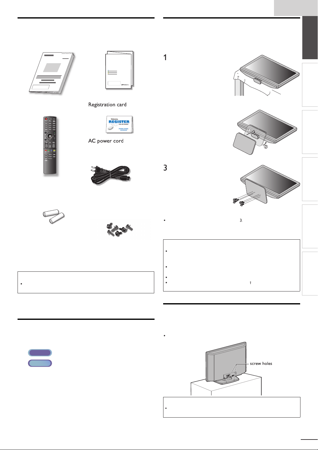
Attaching the Base
ou must attach the base to the unit to have it as a table top
nit. Be sure the front and rear of the base match the proper
rection
Spread a thick and soft
oth over a table as
own
lace the main unit face
u
onto it. Make sure not
amage the screen. At
east 2 people are required
for this step
Insert 2 hooks under the
bottom of the main unit
nto base holes. (shown by
arro
), then move the
ase in the direction as
own by arrow
r
tops and the 6 mountin
oles are a
ve
ps head screws
until it
nto the 6 threaded holes
at the bottom of the base
unt
are t
To remove the base from this unit
nscrew the
fter the screws are removed, move the base in the opposite direction as
own by arrow
nit. Be careful not to drop the base when you remove it
ps head screws on step
on step 2, then pull the base up toward the front of the
Note
hen attaching the base, ensure that all screws are tightly fastened. If the
base is not properly attached, it could cause the unit to
njuries as well as damage to the unit
Make sure to use a table which can support the weight of this unit and is
arger than this unit
ake sure the table is in a stable location
hen attaching the base, ensure that FRONT
upward. If it's not upward, the 2 hooks don't fi t in the base
all, resulting in
written on the base is
PREPARATION
WATCHING TV
OPTIONAL SETTING
TROUBLESHOOTING
INFORMATION
Symbols Used in this Manual
he following is the description for the symbols used in
his manual. Description refers to
: Digital TV operation
: Analog / Cable TV oper ation
If neither symbol appears, the operation is applicable to
ot
Fixing the Unit on Your Furniture
crew this unit on your furniture tightly using wood screws
(not supplied) in the 2 holes at the back of the base as shown
Recommended screw dimension : 5.1 x 20 m
ear of this unit
Note
When you remove this unit make sure to unscrew the wood screws from
our Wood Stand, Furniture and other wood item
Page 6
P
r
(
)
.
7
P
r
(
)
.
4
R
5
P
T
d.
w
l.
Ligh
.
r
Ligh
.
w
.
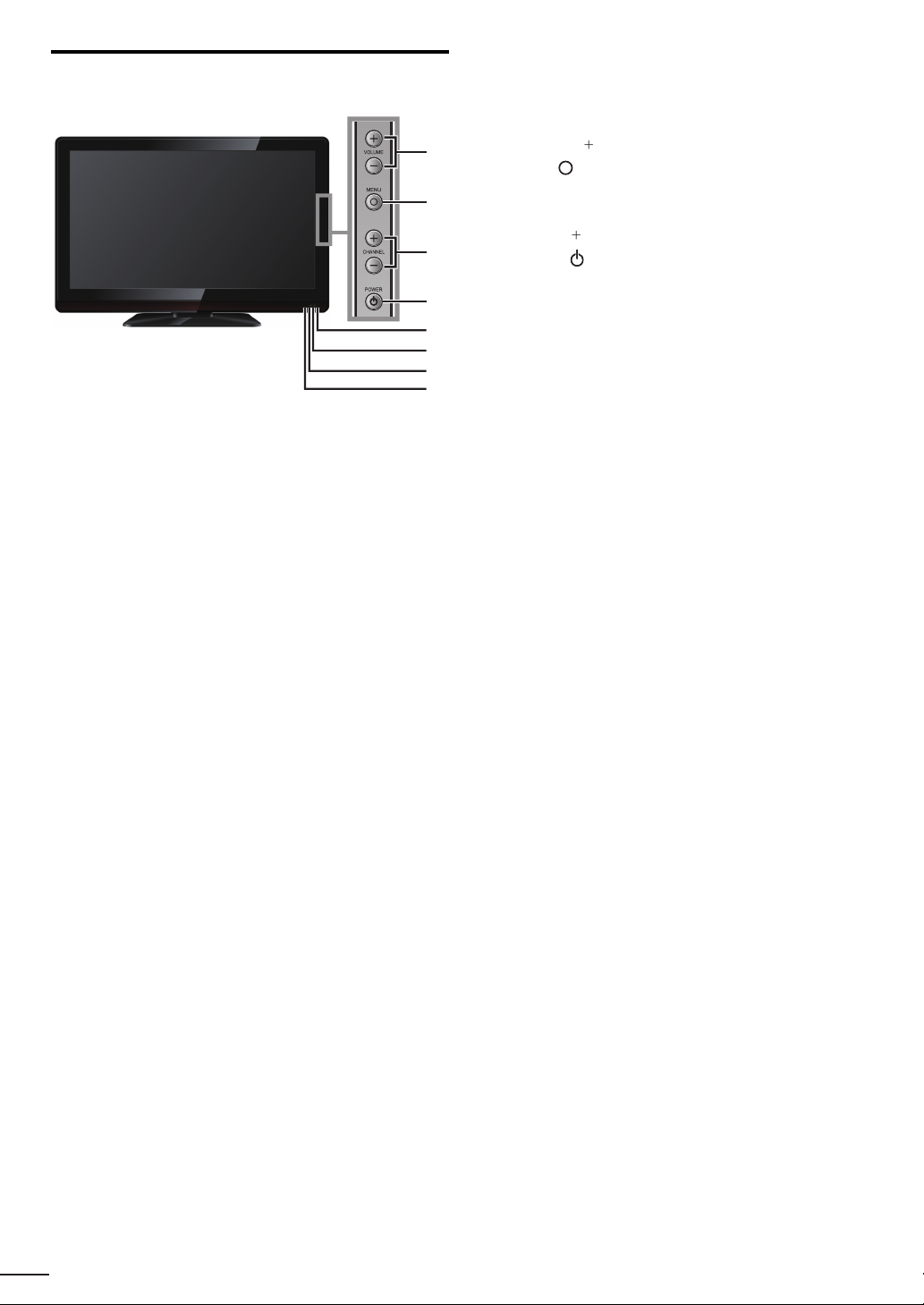
Control Panel
VOLUME + / −
ress to adjust the volume o
1
move right
/ left (–) through the main menu items
2
2
3
4
5
6
7
8
HANNEL + / −
ress to select channels o
move up
/ down (–) through the main menu items
OWE
ress to turn the unit on and go to the standby mode.
o completely turn off the unit, you must unplug the AC
power cor
Infrared sensor windo
Receives infrared rays transmitted from the remote
ontro
OWER indicator
ts up green when power is on
p. 16
p. 19
p. 1
p. 1
STAND BY indicato
ts up red when the unit goes to standby mode
8
uminance sensor windo
Alters the brightness of the TV screen automatically by
etecting your room lighting level. Do not block anything
n front of its window to work properly
Page 7
h
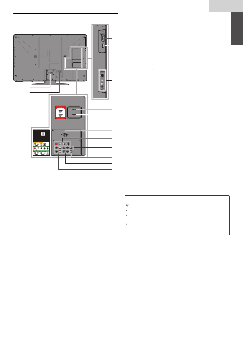
Terminals
l
0
l
AC power
4
.
,
y
s
1
s
1
.
,
ll.
.
l
).
T
d
s
11
12
Side Pane
9 HDMI 3 Input jack
9
*
0 S-Video / Composite Video / Audio (L/R)
Input jacks for VIDEO 2
ear Pane
able management
2
cord Inlet
3 HDMI 2 Input jack
10
HDMI 1 Input jack
HDMI connection for HDMI or DVI device
When you connect your PC that has a DVI terminal
ou can enjoy this unit as a PC monitor.
5 Antenna Input jack
13
14
6 S-Video / Composite Video / Audio (L/R)
Input jacks for VIDEO 1
7 Component Video and Audio (L/R) Input jack
15
16
8 Digital Audio Output jack
9 Analog Audio (L/R) Output jack
17
20 Analog Audio (L/R) Input jacks for HDMI
18
19
20
Audio cable connection from a DVI device
When you connect your PC that has a DVI terminal
use a stereo mini plug conversion cable as we
(For HDMI 1Input jack only)
Note for service terminal
service terminal (service use only)
se this terminal only when a software update is necessary
ser should not connect any devices to the serviceterminal such as digita
camera, keyboard, mouse, etc. (because these will not work
he software update is, in most cases, handled by an authorized ser vice
person or in some circumstances the user may be asked to do the software
ate themselve
up
9, 1
1,
.
p. 1
9, 10
9, 10, 13
9
1,
9 , 1
.
.
, 13
nglis
INTRODUCTION
2
2
PREPARATION
WATCHING TV
OPTIONAL SETTING
TROUBLESHOOTING
INFORMATION
Page 8
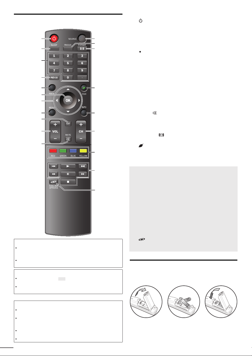
Remote Control Function
1
5
7
6
3
11
9
10
2
4
8
15
17
16
14
12
13
18
19
20
t
.
.
.
pli
.
.
.
.
.
5
.
T
d.
7
.
4
7
P
l.
P
.
5
5
MENU
7
.
7
.
igh
.
7
.
H
G
the disc.
B
k.
E
D
.
F
k.
C
k.
HDMI
.
.
(power)
Press to turn the unit on and go to the standby mode
o completely turn off the unit, you must unplug the AC
power cor
➠
SLEEP
Number buttons
➠
(dot)
Press to shift the subchannel from the main channel
PREV CH
ress to return to previously viewed channe
BACK
ress to return to the previous menu operation
OK
▲/▼/
8
/►
cursor)
➠
➠
➠
9 SAP
0 VOL +/−
1
SOURCE
3
Press to freeze screen image
4 FORMAT
Press to select aspect ratio available for the TV screen
5 ECO
Press to reduce the br
tness
6 INFO
7
H +/−
8 RED / GREEN / BLUE / YELLOW
unctionally useful for Fun-Link
9
/
ress to skip backward or forward chapters, titles or tracks of
➠
➠
➠
➠
➠
➠
p. 1
p. 16
p. 1
p. 1
p. 18
p. 1
p. 1
p. 19
p. 16
p. 16
p. 16
p. 1
p. 16
p. 1
p. 18
p. 18
p. 1
p. 29
p. 29
When using a universal remote control to operate this unit.
ake sure the component code on your universal remote control is set
o our brand. Refer to the manual accompanying your remote control for
more details
We do not guarantee 100% interoperability with all universal remote
ontrols
Note
Buttons in gray background ( ) are not available unless you are
onnected to devices that are compatible with Fun-Link function
We do not guarantee 100% interoperability with other brands of HDMI link
om
ant devices
Battery Precautions:
Be sure to follow the correct polarity as indicated in the battery
ompartment. Reversed batteries may cause damage to the device
Do not mix different types of batteries together (e.g. Alkaline and
arbon-Zinc, or rechargeable batteries like ni-cad, ni-mh, etc) or old
atteries with fresh ones
If the device is not to be used for a long period of time, remove the
atteries to prevent damage or injury from possible batter y leakage
o not try to recharge batteries; they can overheat and rupture
8
ress to begin the disc playbac
/
ress to search backward or forward through the disc
p. 29
p. 29
p. 29
ress to pause the disc playbac
p. 29
ress to stop the disc playbac
20 FUN-LINK OPTIONS
Press to call up various menu from your Fun-Link device
connected through an
cable
p. 18, 29
Installing the Batteries
Install the batteries (AAA, 1.5V x 2) matching the polarity
ndicated inside battery compartment of the remote control
Page 9
h
PREPARATION
.
p
anal
a
l
t
ilabl
5
,
v
.
.
.
insid
.
T
ily b
l
HDMI
t
.
t
h
ll
x
l
PPV
component video cablescomponent video cables
and audio and audio
cables
th
Y
lli
HDMI
t
.
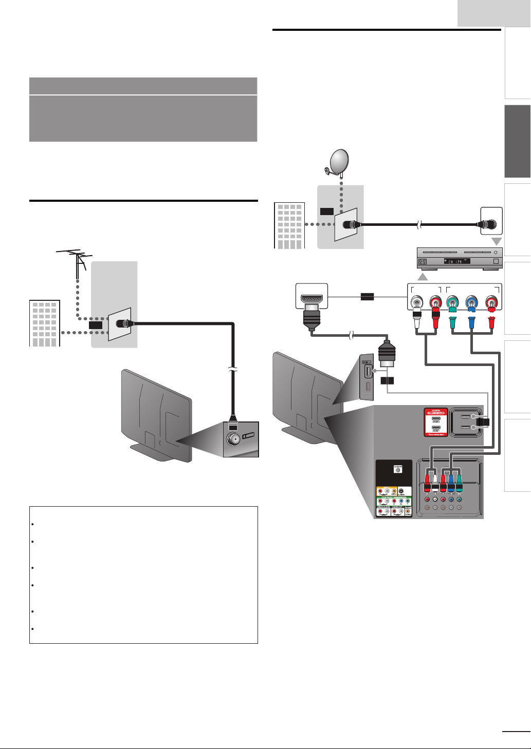
No supplied cables are used with these connections:
Please purchase the necessary cables at your local store.
Use an HDMI cable with the HDMI logo (a certifi ed HDMI cable).
High Speed HDMI cable (also known as HDMI category 2
cable) is recommended for the better compatibility.
Before you connect:
e sure your antenna or other device is connected properly
before plugging in the AC power cord
Connection to Cable Receiver or Satellite Box
se an
HDMI or the Component Video Input jacks of the unit to
he HDMI or the component video output jacks of the cable
receiver / satellite box
If you connect to the unit’s Component Video Input jacks,
onnect audio cables to the Audio L/R Input jacks right beside
he Component Video connector.
e.g.)
or component video cables to connect the
satellite dis
nglis
INTRODUCTION
INTRODUCTION
PREPARATION
PREPARATION
WATCHING TV
Antenna Connection
onnect the RF coaxial cable on your home outlet to the
antenna in
e.g.)
VHF / UHF
cable TV signa
nce connections are completed, turn on the unit and begin initial
setup. Channel scanning is necessar y for the unit to memorize all
ava
Note
If you have any question about the DTV’s antenna
Depending on your antenna system, you may need different types of
combiners (mixers) or separators (splitters). Contact your local electronics
store for these items
For your safety and to avoid damage to this unit, please unplug the RF
coaxial cable from the antenna input jack before moving the unit
If you use an antenna to receive analog TV, it should also work for DTV
reception. Outdoor or attic antennas will be more effective than a set top
or
antenna se
If you are not receiving a signal from your cable service, contact the Cable
ut jack of this unit.
og
or
antenn
or
ear of this uni
e channels in your area.
isit www.antennaweb.org for further information
e antenna
o switch your reception source eas
ector.
rovider.
Initial Setup]➠ p. 1
coaxial cable
etween antenna and cable, install an
cable TV signa
including
HDMI OUT
or
cable receiver /
sate
or
cable
coaxial cable
ite bo
AUDIO OUT
COMPONENT VIDEO OUT
RL
ANT IN
STEREO
PCM
or
or
ide or rear of
is unit
ou can also connect this unit to the cable receiver or sate
ther than the
or the component video output jacks because
te box
hey might have different output jacks
Required cables and connecting methods of the cable receiver /
satellite box, or the availability channel for the clear QAM may differ
epending on the cable / satellite provider. For more information,
please contact your cable / satellite provider.
OPTIONAL SETTING
Pr/CrPb/CbY
TROUBLESHOOTING
INFORMATION
9
Page 10
External Device Connection
y.
video and multi-channel digital audio through a single cable.
)
h the HDMI
k
HDMI-DVI
ipped with DVI
To HDMI1
To HDMI1
conversion cableconversion cable
with the DVI
k
aud
s
t
HDMI
T
1080i
.
T
.
Y
.
T
.
HDMI-DVI
T
1080i
.-DVI
.
.
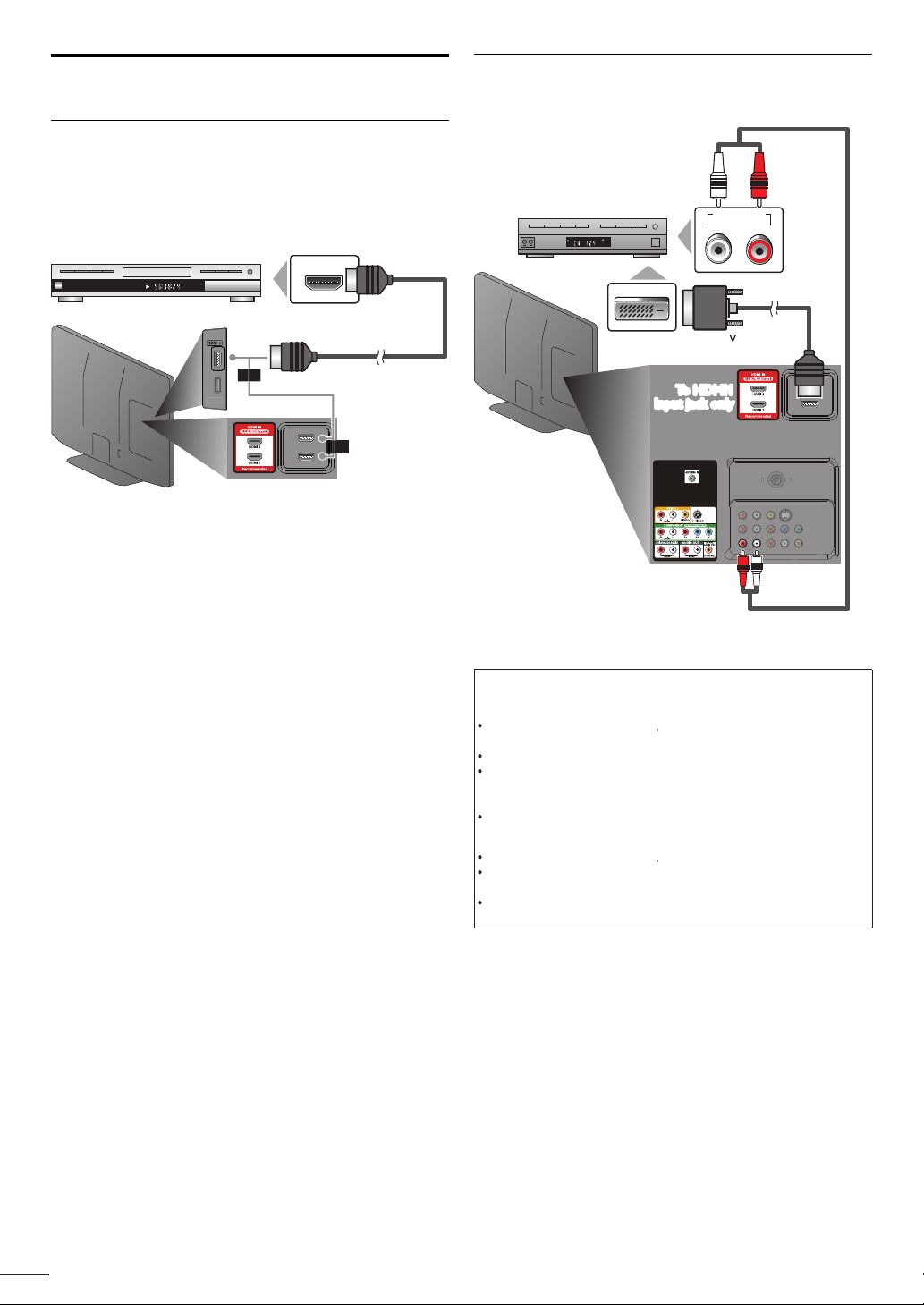
HDMI Connection
HDMI connection offers the highest picture qualit
(High-Defi nition Multimedia Interface) transports high defi nition
e.g.
BD/DVD recorder
wit
TITLE 5
CHAPTER 15
REPEAT A-B
output jac
HDMI OUT
or
cable
HDMI-DVI Connection
se an
xternal video devices equ
e.g.)
cable receiver or satellite box
conversion cable to connect the unit to
output jac
STEREO
PCM
DVI OUT
output jack.
AUDIO OUT
RL
side or rear of this unit
or
ear of this uni
io cable
Note
or
or
connection
he unit accepts 480i, 480p, 720p
ignals, and 32kHz, 44.1kHz and 48kHz of audio signals
his unit accepts only 2 channel audio signal (LPCM)
ou need to select "PCM" for the digital audio of the device you connected
r check the HDMI audio setting. There may be no audio output if you
elect "Bitstream", etc
his unit accepts only signals in compliance with EIA861
and 1080p 24/30/60Hz of video
connection
he unit accepts 480i, 480p, 720p
connection requires separate audio connections as well and the
audio signals are converted from digital to analog
DVI does not display 480i image which is not in compliance with EIA/
EA-861/861B
and 1080p video signals
Page 11
h
1
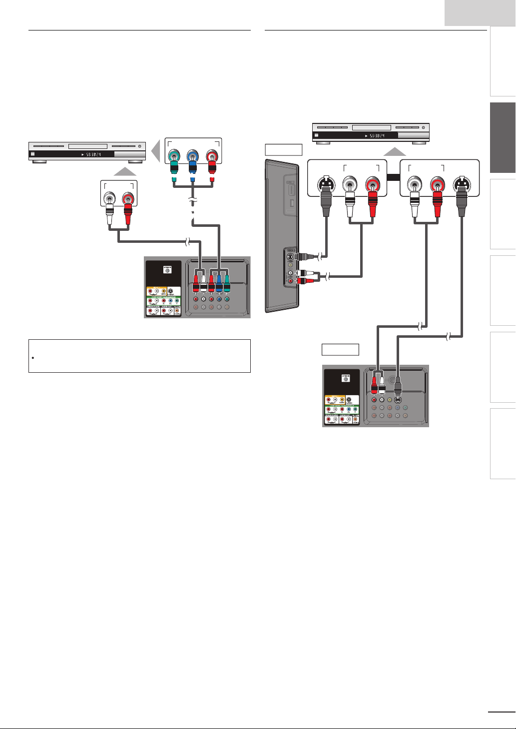
Component Video Connection
id
.
t
CHAPTER 15
REPEAT A-B
TITLE 5
COMPONENT VIDEO OUT
Pr/CrPb/CbY
AUDIO OUT
RL
k
t
aud
s
component video cables
component video cables
T
ion.
p
CHAPTER 15
REPEAT A-B
TITLE 5
AUDIO OUT
RL
S-VIDEO
OUT
AUDIO OUT
RL
S-VIDEO
OUT
t
ocabl
aud
s
aud
s
t
omponent Video connection offers better picture quality for
v
eo devices connected to the unit
If you connect to the unit’s Component Video Input jacks,
onnect audio cables to the Audio L/R Input jacks right beside
he Component Video connector.
e.g.)
BD/DVD recorder with
the component video output jac
S-Video Connection
-Video connection offers good picture quality for video
evices connected to the unit. If you connect to the unit’s
-Video Input jack, connect audio cables to the Audio L/R
In
ut jacks right beside the Composite Video connector.
.g.)
VIDEO2
BD/DVD recorder, camcorder and
VCR with the S-Video output jack
nglis
INTRODUCTION
PREPARATION
io cable
rear of this uni
Note
he unit accepts 480i / 480p / 720p and 1080i of video signals for this
connect
S-Vide
side of this uni
e
io cable
VIDEO1
ear of this uni
or
io cable
S-Video cable
WATCHING TV
OPTIONAL SETTING
TROUBLESHOOTING
INFORMATION
1
Page 12
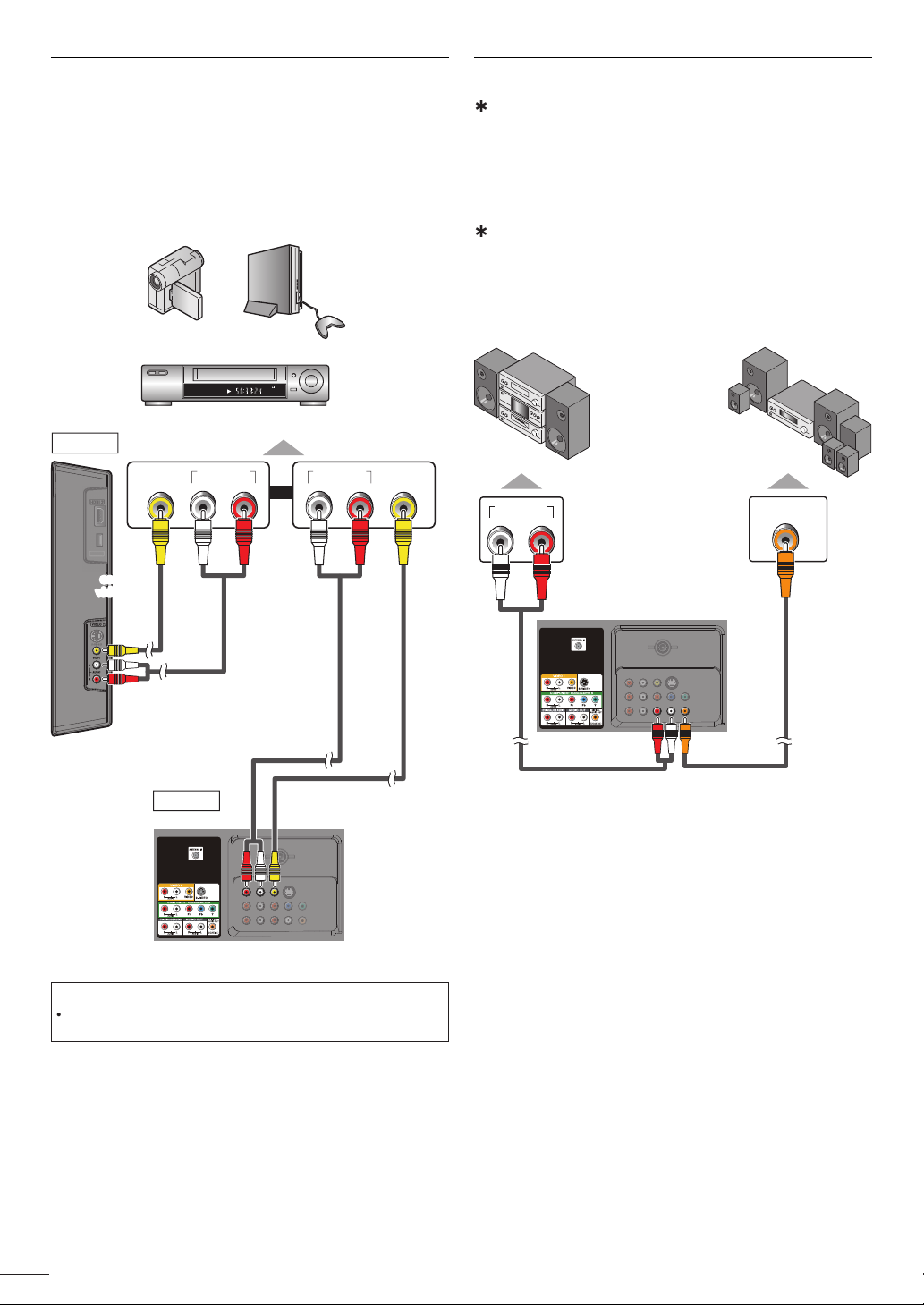
Composite Video Connection
y
t
t
V
A
.
STEREO
STAND-BY
AUDIO OUT
RL
VIDEO
OUT
AUDIO OUT
RL
VIDEO
OUT
vid
t
co
composite
v
video cable
aud
s
aud
s
t
.
)
y
d.
.
A
,
y
.
dio devi
.
DIGITAL AUDIO
COAXIAL IN
AUDIO IN
RL
t
aud
s
Audio Output Connection
omposite Video connection offers standard picture quality
for video devices connected to the unit. If
ou connect to
he unit’s Composite Video Input jack, connect audio cables
o the Audio L/R Input jacks right beside the Composite
ideo connector. When the audio jack of the video device is
monaural, connect an audio cable to the
e.g.)
camcorder
VIDEO2
eo game
VCR
udio L Input jack
or
igital(for digital broadcasting only
If you connect this unit to an external digital audio device,
ou can enjoy multi-channel audio like 5.1ch digital
roadcasting soun
se a digital audio coaxial cable to connect the unit to
xternal digital audio devices
nalog (for both analog and digital broadcasting)
If you connect this unit to an external analog audio device
ou can enjoy stereo (2-channel) audio
se audio cables to connect the unit to external analog
au
.g.)
stereo system
ces
ear of this uni
olby Digital
ecoder
io cable
side of this uni
VIDEO1
ear of this uni
io cable
composite video cable
Note
If you connect to the S-Video Input jack and the Composite Video Input
jack at the same time, the S-Video connection will have priority
io cable
igital audio coaxial cable
2
Page 13

h
PC Connection
T
.
qui
ll.
s
DVI
t
To HDMI1
To HDMI1
DVI
l
T
:
t
n
VGA
A
XGA
4
x
7
WXGA
x
7
x
7
.
DVI
.
.
.
.
his unit can be connected to your PC that has a DVI terminal
se an HDMI-DVI conversion cable for this connection and it
re
res stereo mini plug conversion cables as we
If you connect this unit to your PC, you can use this unit as a
C monitor.
e.g.)
ear of this uni
nglis
INTRODUCTION
PREPARATION
WATCHING TV
OPTIONAL SETTING
stereo mini plug
conversion cable
-
persona
computer
DVI OUT
should be with ferrite core.
conversion cable
-
conversion cable
he following video signals can be displayed
orma
esolutio
Refresh rate
640x480
VG
800x600
02
280
360
68
68
68
60Hz
920x 080
ther formats or non-standard signals will not be displayed
orrectly
Note
ease purchase the
The following operations may reduce noise
- Attach a ferrite core to the AC power cord of your PC
- Unplug the AC power cord and use the built-in battery of your PC
-
conversion
able that has a ferrite core
TROUBLESHOOTING
INFORMATION
13
Page 14

Cable Management
.
t
.
A
d
A
t
t
).
.
Each ti
.
eep the cables through this holder to avoid tangling them
ear of this uni
Use the following accessory with this connection:
• AC power cord x 1
Plug In the AC Power Cord
Make sure that the AC power cord must be plugged to an AC
utlet after all the necessary connections are completed
ear of this uni
Caution:
Do not connect the AC power cord to a power supply outside the
ndicated voltage of this unit (AC 120V
onnecting the AC power cord to a power supply outside of this range may
result in fi re or electrical shocks
Note
me you plug in the AC power cord, no operations will be performed
for a few seconds. This is not a malfunction
C power cor
C outle
Page 15

h
5
These operations are accessible by remote control.
T
d
i
.
:
.
A
,
.
.
it i
.
(Eng
TV
.
]
ill begin.
4
U
ill b
i
ibl
®
.
t
to y
.
Wh
g
the l
ill be displ
.
ider
duri
ill b
d.
T
the i
.
Y
y
.
A
.
]
.
]
0
.
]
1
.
]
0
Some may also be accessible by controls on the main unit.
se
/► to select the desired location setting, then
press
Initial Setup
nglis
INTRODUCTION
Initial Setup
his section will guide you through the unit’s initial setting
which includes selecting a language for your on-screen menu
an
autoprogram, which automatically scans and memorizes
v
ewable channels
Before you begin
ake sure the unit is connected to antenna or cable
1
fter making all the necessary connections
press to turn on the unit
It may take a few moments to turn on the unit for the
first time
Initial Setup]menu appears automatically after the
un
s turned on
2
se ▲/▼ to select the on-screen language from the
choices
screen
3
se ▲/▼ to select Antenna]for TV channels or
for CATV channels, then press
Initial Setup
Make sure the antenna is connected to ''ANT. IN'' jack.
Select your signal source.
Initial Setup
lish / Español / Français) on the right side of the
Antenna
Select OK Back Skip
Cable
Or
ANT.IN
utoprogram]w
Please wait while the system is scanning for channels.
Auto programming may take more than 20 minutes to complete.
0%
Digital channels
Analog channels
0 ch
0 ch
Skip
Antenna
Cable
Skip
able
Select “Retail” or “Home” for your location.
Home
e set up with
Retail
Select OK
elect
etail] store, the unit w
predefined setting for retail displays. In this setting, the
power consumpt
on may poss
y exceed the limited
qualification
elect
ome], the unit is set to maximize the energy
efficiency for home setting and it can be adjusted
hrough a choice of picture and sound quality according
our preference
en the initial setup is completed, the lowest
memorized channel with the confirmation messa
ocation setting w
ayed on the TV screen
Note
If you are not receiving a signal from your cable service, contact the Cable
.
prov
If you pressr
he initial autoprogram function can be executed for either
Cable]only once. When you change the connection (Antenna / Cable),
etutoprogram]again.
If there is no signal input from the antenna terminal and no operation for
everal seconds after you turn on the unit,
nstructions listed on the TV screen
Initial Setup
No channel is registered.
Try Autoprogram again?
Verify that you have a cable connected to the "ANT. IN" jack on the
back of the TV, the channel installation process searches this
connection. If you are using a cable or satellite box, please confirm the
input which you have connected the box and press "SOURCE" key on
the remote control to select the appropriate source input.
ou must set
ou adjusted will not be memorized after the unit goes to the standby mode
ome] in step 4. Otherwise,
ng autoprogram, this setting w
p. 19
Helpful Hints] appears. Follow
Select OK Skip
icture]and
e cancele
ntenna]or
Retry
Later
Sound]settings
fter an initial setup is completed...
If you want to scan the channels automatically again
utoprogram
You can add the desired cable and analog channels
nmemorized by autoprogram
Add Channels
If you want to change to another language
Language Selection
If you want to change the location setting
ocation
p. 19
p. 2
p. 2
p. 3
PREPARATION
WATCHING TV
OPTIONAL SETTING
e of
TROUBLESHOOTING
INFORMATION
1
Page 16

WATCHING TV
.
.
Th
ill
d.
T
.
t
s
).
once to call up the display for checking the remaining time.
T
repeatedly until
d.
.
.
will be displayed for a few seconds
wh
.
to turn off the sound temporarily.
w
.
again or
V
l
.
AT S C
AP
repeatedly to cycle through the available audio languages.
A
.
glish,
.
11.1
NTSC
to display the currently selected audio mode.
th
l.
Freeze Mode
ress
e sound output w
o cancel freeze mode, press any buttons except
an freeze the image shown on the TV screen for 5 minutes
to freeze the image
Freeze
not be pause
Sleep Timer
an be set the unit to go to the standby mode after an incremental period of time
ress SLEEP repeatedly to change the amount of time (ncreases
he time by 30 minutes up to 120 minute
o cancel sleep timer, press
splaye
Sleep Off] is
Sleep 120min.
Sound Functions
escribe how to change the audio or the audio language as well as the volume
Volume Adjustment
se VOL +/− to adjust the volume
Volume 30
en adjusting the volume
Silence Mode
ress
hi!
hola!
salut!
Mute
ress
volume
ill be displayed for a few seconds
Switching Audio Mode
ress S
vailable languages differ depending on the broadcast
Other] is displayed when the audio language cannot be
acquired, or the acquired languages are other than En
panish or French
While receiving an MTS broadcast, press repeatedly to cycle
rough the available audio channe
.g.)When all audio are available
SAP / STEREO
SAP / STEREO
TEREO : Outputs stereo-audio
AP : Outputs second audio program
MONO: Outputs mono-audio
SAP / MONO
6
OL +/− to recover the origina
English 1/3
SAP / STEREO
11
Page 17

h
Switching Each Input Mode
.
.
.
put
)
.
dly
.
l
l
Wid
d
Z
l
.
.
d
v
.
Z
with
.
Wid
Thi
.
l
l
Wid
d
Z
l
.
.
d
t
t
.
Z
t
.
Wid
th
.
For PC input signal
through
de
l
ll
l
.
ll
.
t
iginal size.
s
T
s
T
s
the Number buttons
AT S C
1
.
l.
NTSC
1
[A
ill
l.
external devices when they are connected to the unit
ress
OURCE or
e.g.)
DTV / TV channel
ressing
H +repeatedly to cycle through the input modes
H−reverses the direction of the input modes
an easily switch with the remote control between TV (ATSC or NTSC) and
ComponentVideo2 HDMI1 HDMI2 HDMI3Video111.1
PC in
TV Screen Display Mode
types of display modes can be selected when the broadcasting station is sending 16:9 or 4:3 video signal. And 3 types of display
modes can be selected for PC input signal
ress FORMAT repeate
or 16:9 video signa
orma
e
or 4:3 video signa
orma
e
orma
to switch the TV aspect ratio
4:3
oom
16:9
oom
HDMI1
Input mo
u
ovie Expan
ovie Expan
ot By Dot
isplays a 16:9 picture at its original size
orma
isplays a 16:9 picture at a 4:3 size; the picture
4:3
s shortened horizontally. Sidebars appear on both
edges of the screen
ovie Expan
ertically stretched to fi ll the screen. This only crops
out the top of the picture
oom
out changing its horizontal and vertical ratio
e
crops out the left and right sides of the picture
orma
idebars appear on both edges of the screen
isplays a 4:3 picture at a 16:9 size; the picture is
16:9
stretched horizontally to fi ll the screen
ovie Expan
he picture is stretched more vertically at the top of
he screen. This crops out the top of the picture
oom
maximum size that is more vertically stretched to fi ll
he screen. This crops out the top and bottom of the
picture
e
original size and the edges stretched horizontally to fi ll
e screen
orma
idebars appear on both edges of the screen
isplays a picture that is stretched out of
u
proportion horizontally to fi ll the screen
ot By Do
isplays a 16:9 picture that is
isplays a 16:9 picture at its maximum size
splays a horizontally stretched picture.
isplays a 4:3 picture at its original size.
isplays a 4:3 picture at a 16:9 size;
isplays a 4:3 picture at a 16:9 size; at its
splays the picture with its center at the
splays a proportionately stretched picture.
splays a picture in its or
nglis
INTRODUCTION
PREPARATION
WATCHING TV
OPTIONAL SETTING
s
TROUBLESHOOTING
INFORMATION
Channel Selection
elect channels by using H/− or the Number button
o select the memorized channels, use H/− or the
o select the non-memorized channels, usethe Number button
o use
When selecting digital channel 11.
e sure to press ●before entering the subchannel number
REV CH to return to the previously viewed channe
[No Signal] will appear on the TV screen after the subchannel broadcast is over.
udioonly program] message w
Note
umber button
When selecting cable or analog channel 1
appear on the TV screen, when you receive only sound signa
11.1
Page 18

TV Screen Information
O
AT S C
11.1
TV: TV-14
1080i
1080i
16:9
16:9HDHD
CC
CC
KABC
KABC
1 23 4
5
6, 7, 8
9
10
A
NTSC
1
2
prog
)
r
)
6
7
]
)
hild lock
.
Y
K
ll.
]
is displayed wh
d.
d.
;
Vid
k.
T
.
0
.
h
iority.
Y
0
h
.
Y
d
y
.
a
;
X
X
F
7
1
s
y
Link
Opt
Opt
Opt
p
p
ions
T
t
T
t
.
e
T
.
U
.
.
W
li
.
You can display the currently selected channel or other
information such as the audio mode on the TV screen.
In the digital mode, the detailed broadcasting information for
the current channel such as program title, program guides are
displayed.
ress INF
A Day of Memories
Day of Memories
A quarter-century ago,which may now qualify as the
good old days of newspapering,run-of-paper sales
accounted for 80 percent of the industry's advertising
revenues.Department stores and supermarket were
4
11
SAP / STEREO
480i
480i
TV-PG DLSV
5
4:3SDSD
4:3
6, 7, 8
CC
CC
9
10
rogram title
ram guide
The program guide added to broadcasting
nformation is displayed to a maximum of 4 lines.
3broadcast station
channel numbe
5 audio language (ATSC) / audio mode (NTSC
Switching Audio Mode]p. 16
effective scanning lines and scan mode
TV format
8 program aspect ratio
9 CC (not available if closed caption is set to
0 c
rating
To clear the display, press INFOagain
ou can also press BAC
Note
When the program guide consists of more than 4 lines, use
o description provided.
rovide
While the program guide is displayed, the closed caption function is
nterrupte
In external input mode, the following screen is displayed
e.g.) When an external device is connected to
English 1/2
Rating
Off
/▼to scro
en the program guide is not
eoInput jac
Reducing the Brightness
Backlight brightness can be reduced which may save on power
consumption more than you just set [On] in [Energy Saving
Mode].
p. 3
ress ECO once to reduce the brightness
ress ECO again to increase the brightness.
Note
Even if this function is in effect, the brightness will be increased when you
ange
Energy Saving Mode]on or off due to the energy saving mode has
c
pr
ou must set
therwise, the settings you adjusted will not be memorized after the unit
goes to t
ome] in
e standby mode
ocation]
p. 3
Fun-Link Options
If you have our brand products such as BD player or DVD
recorder that are compatible with Fun-Link functions, connect
them to this unit via an HDMI cable so you can simply operate
various items from this unit's remote control.
Before you begin:
ou must set
Fun-Link Control]
therwise, FUN-LINK OPTIONS
ou connected our brand devices to this unit
To enjoy Fun-Link, verified and recommended devices
re as follows
MAGNAVO
MBP1100 / F
Pres
Device-menu
Device-contents
Device-favorit
On] in
Device Control] an
. 2 9
B530MG
B500MG1
FUN-LINK OPTIONSto displa
unLink Options] menu
Fun-Link Options
Device-menu
Device-contents
Device-favorite
oes not work even if
SYLVANIA
B530SLX
B500SL
his function allows you to control
he menu of your connected Fun-Link
evice.
his function allows you to control the
op menu of your DVD or Blu-ray discs
his function allows you to control the
pop-up menu of your Blu-ray discs
Video1
SD
480i
SD
480i
TV-PG DLSV
he information display will automatically disappear in 1 minute
8
CC
CC
2
se ▲/▼/◄/► /
on this unit's remote control to
operate the desired functions for your devices
Note
ome of Fun-Link functions may not be available depending on your
un-Link devices or discs
e do not guarantee 100% interoperability with other brands of HDMI link
ant devices
comp
Page 19

h
OPTIONAL SETTING
T
t
.
e
Y
lly
.
[
]
0
T
t
.
[
]
0
th
.
]
4
.
[
7
Y
.
[F
Y
.
]
0
[L
]
0
.
[
]
0
]
1
.
y
DTV ch
t
.
:
.
4
U
W
,
]
W
]
ill begin.
ill be displ
d.
A
kip
ilable prog
lly.
ill b
d.
AC p
g
The PIN
ill b
PIN
]
7
]
Main Menu
his section describes the overview of the main menu
splayed when you press
he function setting items below
ress
Pictur
Picture Adjustment]
Sound [Sound Adjustment]
Setup
utoprogram]
ou can automatica
Channel List
he Channels that were autoprogrammed are in
his Channel list, use
Add Channels
You can add TV channels that were not found by
e autoprogram scan
eatures [Closed Caption
You can change the display closed caption format
which displays the dialogue of a TV program or
other text information across the TV screen
Child Lock]
ou can set viewing limitations
un-Link]
ou can set Fun-Link options
[Energy Saving Mode
ocation
witch setting from
esiredicture] andSound]mode to be kept in
memory
Current Software Info
anguageLanguage Selection
hange the Main Menu language
. The main menu consists of
Picture
Sound
Setup
Features
Language
scan the viewable channels
H + / −to access them
etail] to
ome] to allow the
p. 22
p. 22
p. 19
p. 2
p. 2
p. 2
p. 2
p. 29
p. 3
p. 3
p. 3
p. 2
nglis
Autoprogram
If you switch wires (e.g. between antenna and CATV) or if you
move the unit to a different area after the initial setting, or if
ou restore the
o use Autoprogram to perform a new channel search
Before you begin
ake sure the unit is connected to antenna or cable
Press MENU to display the main menu.
2
se ▲/▼to select
se ▲/▼to select Autoprogram], then press
se ▲/▼to select an appropriate option, then press
Picture
Sound
Setup
Features
Language
hen connected to VHF / UHF antenna
select
Antenna
hen connected to CATV, select
utoprogram]w
Please wait while the system is scanning for channels.
Auto programming may take more than 20 minutes to complete.
75%
Digital channels
Analog channels
When the scanning and memorizing are completed, the
owest memorized channel w
Note
fter setting
unava
If you are not receiving a signal from your cable service, contact the Cable
rovider.
If you press or
Even if
ressin
p. 2
If you want to change your PIN code, follow the instruction of
Change PIN
utoprogram], using
rams automatica
utoprogram] is completed, the channel setting will be lost if the
ower cord is unplugged before the unit goes to the standby mode by
code w
annels you deleted, it is recommended
Setup], then press
Autoprogram
Autoprogram will rescan all channels.
Auto programming may take more than 20 minutes to
complete.
Select your signal source.
Antenna
Cable
Or
Back
Antenna
Cable
ANT.IN
Cable
10 ch
6 ch
Exit
aye
H + / − on the remote control s
during autoprogram, the setting w
e required once you set a
28
code in the
s
e cancele
Child Lock
INTRODUCTION
PREPARATION
WATCHING TV
OPTIONAL SETTING
TROUBLESHOOTING
INFORMATION
9
Page 20

0
Channel List
Th
kipped wh
–
Th
ill b
s
.
T
Y
ill
–
highlighted.
d
ll.
.
Th
.
.
T
l
.
P
.
s
]
.
]
is displ
d.
ill be displ
.
.
e channels selected here can be s
annels using
ose channels can st
H+ /
e selected with the Number button
en selecting the
Add Channels
his function lets you add the channels that were not added
y the autoprogram due to reception conditions at the initia
setting
Press
2
se ▲/▼ to select
3
se ▲/▼ to select
4
se ▲/▼ to select the channel you want to remove, then
to display the main menu
Setup], then press
hannel List], then press
press
Channel List
Picture
Sound
Setup
Features
Language
Highlight channels for Ch
Up / Down key selection.
Ch Select
DTV 6.1
27.1
DTV 8.1
9.1
DTV 48.1
58.1
DTV 67.1
Watch/Skip Back
he channel display for the removed channel darkens.
ou w
not be able to select the channel again using
H+ /
To reactivate a removed channel, use ▲/▼ and press
. The registered channels are
When you remove a main channel, its subchannels are
as we
to exit
5
remove
ress
Note
e channel with the
therwise the channel is NTSC
indicated on the display is ATSC
ress
2
se ▲/▼to select
3
se ▲/▼to select Add Channel
4
se the Number buttons to enter the number of the
to display the main menu
Setup], then press
, then press
annel you want to add, then press
Add Channels
5
ress
Picture
Sound
Setup
Features
Language
For analog channels, select a
channel to be added using number
keys.
For digital channels, you must
perform Autoprogram function.
Ch Change Back
to exit
Add Channels
Note
If setup completes successfully,
If external input is used, it is not possible to register the channel and
navailable] w
y using
H + /
, you can select the memorized channels only
dded to the channel list
ayed on the TV screen
11
aye
2
Page 21

h
1
Antenna Confi rmation
AT S C
T
l.
.
a
]
–
t
h.
dition.
.
h
]
l
]
s
]
.
K
K
.
his function lets you check the digital signal strength of each
anne
Press
2
se ▲/▼ to select
3
se ▲/▼to select Antenn
to display the main menu
Setup], then press
, then press
nglis
Language Selection
You can choose English, Spanish, or French as your on-screen
language.
1 Press MENU to display the main menu.
2
se ▲/▼to select anguage], then press
3
se ▲/▼to select
nglis
press
spaño
or
rançai
then
INTRODUCTION
PREPARATION
4
se the Number buttons or
H+ /
o select the
channel for which you want to check the digital signal
strengt
Antenna
Picture
Sound
Setup
Features
Language
Current 50 Max 50
Ch Change
If the channel is set to analog (cable) channel or
external input, you cannot confirm the antenna
con
Video1
Antenna
Picture
Sound
Setup
Features
Language
Indicator is available
for digital broadcasting
only.
Ch Change
Back
Back
11.1
Language
4
ress
Picture
Sound
Setup
Features
Language
Select your menu language.
Seleccione el idioma para el menú.
Sélectionnez la langue du menu.
to exit
English
Español
Français
Note
If you need the English menus instead of the Spanish or French menus, press
. Use ▲/▼to select
se ▲/▼ to select
ress
to exit the main menu
ioma]or
nglish], then press O
angue], then press O
WATCHING TV
OPTIONAL SETTING
TROUBLESHOOTING
INFORMATION
5
ress
to exit
2
Page 22

Picture Adjustment
Y
]
i
0
.
.
Adj
.
e
Mode
]
)
e
Y
t
.
igh
s
to i
igh
s
t
t
to i
t
to i
Tint
d
t
e
lors
l
s
.
Y
.
Y
]
i
0
.
.
You can adjust picture mode, or customize the picture quality
as your preference.
Before you begin:
ou must set
therwise, the settings you adjusted will not be memorized
after the unit goes to the standby mode
1
ress
2
se ▲/▼ to select
3
se ▲/▼ to select the item you want to adjust, then press
ome
n
ocation]
to display the main menu
icture], then press
p. 3
Sharpness
Sharpness 0
Adjust Move OK
olor Temperatur
Color Temp. Normal
Adjust Move OK
5
ress
OK
OK
to exit
ress
to soften
ress
to add warm
co
ress
to sharpen
ress
to add coo
color
Sound Adjustment
ou can adjust the sound mode, equalizer and some other
sound functions
Picture
Picture
Sound
Setup
Features
Language
4
ust the following items
Picture Mode
Brightness
Contrast
Color
Tint
Sharpness
Color Temperature
Pictur
se ▲/▼to select the desired setting, then press
ersonal]
Picture
Sound
Setup
Features
Language
Standard]
Picture
Picture Mode
Brightness
Contrast
Color
Tint
Sharpness
Color Temperature
Sports]
Personal
30
60
36
0
0
Normal
ovie] and
Game
Personal
Standard
Sports
Movie
Game
Before you begin:
ou must set
therwise, the settings you adjusted will not be memorized
after the unit goes to the standby mode
1
ress
2
se ▲/▼to select
3
se ▲/▼to select the item you want to adjust, then press
Picture
Sound
Setup
Features
Language
ome
n
ocation]
to display the main menu
ound], then press
Sound
Sound Mode
Equalizer
Virtual Surround Sound
Auto Volume Leveling
TV Speakers
Primary MTS
p. 3
Standard
On
Off
Ext. Amp
Stereo
22
Sharpness
Color Temperatur
ou can only adjust the following options when you set
o
ersonal] in
esired setting, then use
rightness
Brightness 30
Adjust Move OK
ontras
Contrast 60
Adjust Move OK
olor
Color 36
Adjust Move OK
Tint 0
Adjust Move OK
Picture Mode]. Use ▲/▼ to select the
/► to adjust
ress
OK
OK
OK
OK
to decrease
r
tnes
ress
to decrease
contras
ress
to decrease
color intensity
ress
to add re
ress
ncrease
r
tnes
ress
ncrease
ontras
ress
ncrease
olor intensity
ress
o add green
Page 23

h
4
A
.
de
]
)
Adj
p
Vi
l
▼
.
f
.
A
T
.
TV
.
f
.
HDMI
t
]
T
k
.
f
T
’
.
Y
HDMI link devi
'
.
pli
.
Y
.
Thi
o
.
o
.
.
.
djust the following items
Sound Mo
se ▲/▼ to select the desired setting, then press
ersonal]
Picture
Sound
Setup
Features
Language
Standard]
Sound
Sound Mode
Equalizer
Virtual Surround Sound
Auto Volume Leveling
TV Speakers
Primary MTS
ovie]
Equalizer
ust tonal quality for each frequencies. Use
select the s
evel, then press
Picture
Sound
Setup
Features
Language
ecifi c frequency and use ▲/▼to adjust the
Equalizer
0
120Hz0500Hz01.5kHz05kHz010kHz
usic] and
Personal
Standard
Movie
Music
News
ews
/►to
n
f
Reduces volume differences between the
commercials and the programs
emoves the auto volume leveling
TV Speakers
elect the audio output from the unit’s speakers, or not.
If your amplifi er is HDMI link function compatible and
onnected by an
perations such as volume up can be changed by using
his unit’s remote control. Make sure
s set to
On] ➠p. 29
se ▲/▼to select the desired option, then press
Picture
Sound
Setup
Features
Language
n
f
xt. Amp
cable to this unit, some sound
Fun-Link Control
TV Speakers
"On":
Sound will be output from the TV
speakers.
"Off":
Sound will not be output from the
TV speakers.
"Ext. Amp":
"Operation is possible by connecting
to the HDMI-CEC compatible amp
with a HDMI cable. For details look
in the user manual."
he sound will be output from the unit’s
spea
ers
he sound will not be output from the
s speakers
unit
ou can control audio output from your
onnected
s remote control
unit
On
Off
Ext. Amp
ces by using this
nglis
INTRODUCTION
PREPARATION
WATCHING TV
OPTIONAL SETTING
TROUBLESHOOTING
rtual surround sound gives you the stereo phonic virtua
space through your existing 2-channel stereo system. Use
▲/
to select the desired option, then press
Virtual Surround Sound
Picture
Sound
Setup
Features
Language
This selects the modes for
more spatial or surround sound
reproduction.
On
Off
n Emphasized effect
f
atural effect
uto Volume Leveling
his function keeps a constant loudness differential
etween the TV commercials and the programs
se ▲/▼ to select the desired option, then press
Auto Volume Leveling
Picture
Sound
Setup
Features
Language
Auto Volume Leveling reduces
volume differences between
channels and programs, providing
a consistent audio level.
On
Off
Note
We do not guarantee 100% interoperability with other brands of HDMI
nk com
ant devices
rimary MTS
ou can set the output mode as a default for the sound
mode (NTSC only)
s setting is not interlocked when you change the
utput mode by pressing SAP Sound Functions]p. 1
se ▲/▼to select the desired option, then press
Sound
Picture
Sound
Setup
Features
Language
Stere
on
SAP
ress
Sound Mode
Equalizer
Virtual Surround Sound
Auto Volume Leveling
TV Speakers
Primary MTS
utputs stereo-audio
utputs mono-audio
utputs second audio program
to exit
Stereo
Mono
SAP
INFORMATION
23
Page 24

4
Closed Caption
.
.
A
A. Caption Service
U
Th
p
.
.
T
.
,
T
.
e
ly.
de
th
.
de
g (
).
P
.
You can view closed captioning (CC) for TV programs,
movies and news. Closed caption refers to text of dialogue or
descriptions displayed on-screen.
A. Caption Service
4
se ▲/▼to select aption Service], then press
se ▲/▼to select the desired closed caption, then press
Press
2
se ▲/▼ to select
Use ▲/▼ to select
to display the main menu
eatures], then press
losed Caption], then press
ee the following description for setting each item
Closed Caption
Picture
Sound
Setup
Features
Language
Caption Service
Digital Caption Service
Caption Style
Off
Off
Picture
Sound
Setup
Features
Language
C-1 and T-1
C-3 and T-3
C-2, CC-4
-2 and T-4
Closed Caption
Caption Service
Digital Caption Service
Caption Style
e primary caption and text services. The
aptioning or text is displayed in the same
anguage as the program’s dialogue (up to
4 lines of scri
t does not obstruct relevant parts of the
picture)
erve as the preferred data channels
he captioning or text is often a secondary
anguage
arely available and broadcasters use them
nly in special conditions, such as when
CC-1]and
ot available
t on the TV screen, where
CC-3] or
Off
CC-1
CC-2
CC-3
CC-4
T-1
T-2
T-3
T-4
T- 1] andT- 3] are
• There are 3 display modes according to programs:
Paint-on mod
op-on mo
oll-up mo
ress
splays input characters on the TV screen
mmediate
nce characters are stored in memor y,
ey are displayed all at once
splays the characters continuously by
scrollin
max. 4 lines
to exit
2
Page 25

h
B. Digital Caption Service
B. Digital Caption Service
AT S C
dditi
DTV h
pti
digital
t
.
4
digital
f
.
6
]
i
.
.
.
C. Caption Style
AT S C
Y
tc.
4
U
▼
So, y o u mu st be P hi li p. H i!
I’m p le as ed t o me et y o u.
y
T
.
.
n a
on to the basic closed caption,
ca
on called
caption service. Use this menu to change
he settings for digital caption service
se ▲/▼to select
5
se ▲/▼to select the desired
Digital Caption Service], then press
ress
Closed Caption
6
Picture
Sound
Setup
Features
Language
f
S-1 to CS-
ress
Caption Service
Digital Caption Service
Caption Style
elect if you do not want digital caption
ervice
Select one of these before changing
any other item in
menu. Choose
rcumstances
c
to exit
as its own closed
caption service, then
Off
CS-1
CS-2
CS-3
CS-4
CS-5
CS-6
Closed Caption
CS-1] under normal
C. Caption Style
ou can change the caption style such as font, color or size,
e
se ▲/▼to select
se ▲/▼to select
Picture
Sound
Setup
Features
Language
6
se ▲/▼to select
se ▲/▼to select an item, then press
▲/
to select the desired setting and press
Picture display
So, you must be Philip. Hi!
So, you must be Philip. Hi!
I’m pleased to meet you.
I’m pleased to meet you.
Caption Style], then press
User Setting], then press
Closed Caption
User Setting
Font Style
Font Size
Font Color
Font Opacity
Background Color
Background Opacity
Edge Color
Edge Type
n], then press
Off
Font0
Middle
White
Solid
Black
Solid
Black
None
. Then use
nglis
INTRODUCTION
PREPARATION
WATCHING TV
OPTIONAL SETTING
TROUBLESHOOTING
Note
Digital Caption Service] that you can switch differs depending on the
roadcast description
ge
Edge Color and Edge Type)
ont
Font Style, Font Size, Font Color and Font Opacit
or Transparency)
ackground
( Background Color and Background Opacity or
Transparency)
he setting description for each item is shown on the
ext page
eview your setting choice made on the next page
y looking in the upper right corner of the displayed
etting box (not all selections show the differences
elected)
INFORMATION
25
Page 26

Font Style
ill
d.
d.
r
d.
y
d.
r
itched
ill
d.
itched
ill
d.
r
pti
d.
i
d.
.
ion.
T
i
.
.
.
.
A
ds.
A
.
Th
ill
hil
f
.
]
r
li
:
El
Weak si
T
.
.
losed Captioning font style
an be changed as
ustrate
Closed Caption
Background Opacity
Closed Caption
Background opacity of the
splayed caption can be
sw
as
ustrate
Solid
Flash
Translucent
Transparent
Font Size
ont size of the displayed
aption can be switched as
ustrate
Font Colo
ont color of the displayed
aption can be switched as
ustrate
Font Opacit
ont opacity of the displayed
aption can be switched as
ustrate
Background Colo
Background color of the
splayed caption can be
sw
as
ustrate
Closed Caption
Large
Middle
Small
Closed Caption
White
Black
Red
Green
Blue
Yellow
Magenta
Cyan
Closed Caption
Solid
Flash
Translucent
Transparent
Closed Caption
White
Black
Red
Green
Blue
Yellow
Magenta
Cyan
Edge Colo
Closed Caption
Edge color of the displayed
ca
on can be switched as
ustrate
ge Type
White
Black
Red
Green
Blue
Yellow
Magenta
Cyan
Closed Caption
Edge type of the displayed
capt
on can be switched as
ustrate
None
Raised
Depressed
Uniform
L. Shadow
R.Shadow
8
ress
to exit
Note
losed caption will not be displayed when you are using an HDMI
connect
o show the closed caption on your TV screen, broadcast signal must
n the closed caption data
conta
ot all TV programs and commercials have the closed caption or all types
of the closed caption
aptions and texts may not exactly match the TV voice
hanging channels may delay the closed caption for a few seconds
djusting or muting the volume may delay the closed caption for a few
secon
bbreviations, symbols and other grammatical shortcuts may be used in
order to keep pace with the on-screen action. This is not a malfunction
e caption or text characters w
unctions display is shown
or
If a black box appears on the TV screen, this means that the closed caption
s set to the text mode. To clear the box, select
CC-4] or
If the unit receives poor quality television signals, the captions may contain
errors, or there might be no captions at all. Some possible causes of poo
qua
-Automobile ignition noise
-
-
- Multiplex signal reception (ghosts or screen fl utter)
- Data dropout and Pixelation (for DTV only)
When the unit receives special effects playback signal (e.g. Search, Slow
and Still) from a VCR’s video output channel (ch3 or ch4), the unit may not
Off
ty signals are
ectric motor noise
gnal reception
he unit retains the closed caption setting if the power fails
splay the correct caption or text
not be displayed w
CC-1]
e the main menu
CC-2]
CC-3]
26
Page 27

h
7
Child Lock
t
h
t
ible.
.
]
y
PIN
.
Wh
PIN
ter
0
Wh
PIN
d.
.
A
Wh
high
ill b
y
g.
Wh
high
]
lly.
To block
k]
T
.
ill
ill b
l
.
.
T
y.
A. Channel Lock
ible i
t
.
dly
w
]
d
]
V
o
V
C
1
3
40
.
B. Setting US Movie ratings
.
w
]
d
]
X
7PG-13PG
G
g
y
X
7
d
3
G
d
g
.
hild lock reads the ratings for programs, then denies access
o the programs which exceed the rating level you set. Wit
his function, you can block certain programs inappropriate
for children and any channels or external input modes can be
nvis
1
ress
2
se ▲/▼ to select
3
se ▲/▼ to select
4
se the Number buttonsto enter the 4-digit numbers for
our
to display the main menu
Features
Picture
Sound
Setup
Features
Language
Closed Caption
Child Lock
Fun-Link
Energy Saving Mode
Location
Current Software Info
code
eatures], then press
, then press
On
Home
A. Channel Lock
articular channels or external input modes can be invis
his function
5
se ▲/▼to select
6
se ▲/▼to select the desired rating, then press
7
repeate
ress
to switch between Vie
Picture
Sound
Setup
Features
Language
Channel L], then press
Channel Lock
Select
to exit
ide
ideo2
omponent
DMI
DMI
.1 DTV
View / Block
an
Back
nglis
INTRODUCTION
n
PREPARATION
WATCHING TV
OPTIONAL SETTING
Setup
Features
en you have not set up your
0 0 0
en
en the
Enter PIN.
code is correct,
- ---
code,
Child Lock] menu is
splaye
ee the following description for setting each item
Child Lock
Picture
Sound
Setup
Features
Language
Channel Lock
US Movie Ratings Lock
US TV Ratings Lock
Canadian English Rating
Canadian French Rating
Region Ratings Lock
Clear Region Ratings Lock
Change PIN
Note
en you select a rating and set it to
blocked automaticall
en you set the
automatica
any inappropriate programs, set your limits in
ock]
US TV Ratings Lock]andegion Ratings Loc
he child lock setting will be retained after a power failure (except the PIN
code reverts to 0000)
If the rating is blocked, w
egion Ratings Lock] w
roadcast using the new rating system
or the United States, the unit may download the Region Ratings Lock Table,
f required
he Canadian rating systems on this unit are based on CEA-766-A and
RTC polic
. The lower ratings will be available for viewin
est rating to
appear.
e available when the unit receives a digita
ock], the
iew], all ratings turn to
er ratings w
US Movie Ratings
iew
B. Setting US Movie ratings
TROUBLESHOOTING
S Movie ratings lock is the rating system created by MPAA
5
se ▲/▼to select
6
se ▲/▼to select the desired rating, then press
repeatedly to switch between Vie
Picture
Sound
Setup
Features
Language
e
atin
NC-1
PG-13
P
7
ress
US Movie Ratings Lock], then press
an
US Movie Ratings Lock
-1
Select
View / Block
Back
ategor
ature audience only
o one under 17 admitte
Restricted; under 17 requires accompanying
parent or adult guardian
nsuitable for children under 1
arental guidance suggeste
eneral audience
o ratin
to exit
INFORMATION
2
Page 28

C. Setting TV ratings
C. Setting TV ratings
]
repeatedly to switch between
View
]
]
VST
A
T
G
TV-G
TV-Y7
T
y
TV-MA
T
4
T
G
d
TV-G
TV-Y7
Approp
r
TV-Y
A
r
.
gs
A
t
T
.
dly
k]
V
S
T
A
TV-14
T
G
TV-G
TV-Y7
TV-Y
y
TV-Y7
V
Viol
T
A
T
4
T
G
T
G
ill
.
]
lly chang
(
]
).
D. Change PIN
A
y
PIN
.
.
PIN
.
.
.
.
.
T
.
D. Change PIN
se ▲/▼to select
5
6
se ▲/▼ / ◄/► to select the desired rating, then press
, then press
and
US TV Ratings Lock
Picture
Sound
Setup
Features
Language
ating
V-M
-
V-P
V-Y
Select
V
View / Block
ategor
ature audience only
V-14
V- P
nsuitable for children under 1
arental guidance suggeste
eneral audience
riate for all children 7 and
e
ppropriate for all children
7
ress
to exit
o set the sub ratin
s for TV-MA, TV-14, TV-PG, or TV-Y7, you can further set
he sub ratings to block specifi c elements of programming.
o set the sub ratings, follow the step below
Back
igher
owe
lthough the default PIN code (0000) is supplied with the unit,
ou can set your own
5
se ▲/▼to select
6
ress the Number buttons to enter the new 4-digit PIN
code
hange PIN], then press
ode
7
nter
ress
Picture
Sound
Setup
Features
Language
code again in
Channel Lock
Enter PIN.
Confirm PIN.
to exit
Confirm PIN.] entry field
-
---
- ---
PIN Code
Back
Note
Make sure new PIN code and confi rm PIN code must be exactly the same.
If they are different, the space is cleared for reentering
Your PIN code will be erased and return to the default (0000) when a
ower failure occurs
If you forget the PIN code, unplug the AC power cord while turning the unit
on, wait for 10 seconds to plug the AC power cord again
he unit will restore the PIN code to 0000 as the factory default
se ▲/▼ / ◄/► to select the desired rating, then press
repeate
Picture
Sound
Setup
Features
Language
Sub Rating
S
to switch between
US TV Ratings Lock
V-M
V-P
Select
ategor
antasy Violence
ence
exual Situation
oarse Language
uggestive Dialogue
iew] and
View / Block
V- M
V- 1
V- P
V-14, TV-P
Note
ocked sub rating w
US TV Ratings Lock]menu
You cannot block a sub rating (D, L, S or V) if the main rating is set to
iew
hanging the category to
ratings to the same
appear beside the main rating category in
ock] or
ock] or
iew]automatica
iew
oc
Back
ating
es all its sub
28
Page 29

h
Fun-Link
T
i
HDMI
.
.
Adj
.
]
T
y
]
t
.
fsabl
k.
A
f
Y
t
f
icall
de.
f
th
.
A
Thi
ill
l
.
Thi
y
.
f
T
.
Y
’
.
B
FU
//// /
/
l
fsabl
l.
t
T
.
HDMI devi
the TV
.
his function allows you to operate the linked functions
between our brand devices with a Fun-Link feature and this
un
t connecting through an
1
ress
2
se ▲/▼to select
3
se ▲/▼to select
Picture
Sound
Setup
Features
Language
4
se ▲/▼to select the desired setting, then press
5
ust the following items
to display the main menu
Fun-Link
Fun-Link Control
Auto Device Off
Auto TV On
Device Control
Device List
un-Link Control
et the Fun-Link
he following additional settings will be grayed out when
ou set to
se ▲/▼ to select the desired setting, then press
Picture
Sound
Setup
Features
Language
n
f
On]or
Off
Fun-Link Control
When set to "On", Fun-Link
functions are enabled.
elects if you have connected an external device
hat is compatible with the Fun-Link function
es all Fun-Lin
uto Device Of
ou can set your device to turn off by interlocking from
his unit’s power.
se ▲/▼ to select the desired setting, then press
Auto Device Off
Picture
Sound
Setup
Features
Language
n
f
When set to "On" and TV is
turned off, connected devices
are turned off automatically.
Your connected Fun-Link device turns of
automat
mo
Your connected Fun-Link device stays on even if
e unit goes to the standby mode
cable
eatures], then press
un-Link], then press
Off
y when the unit goes to the standby
nglis
29
INTRODUCTION
PREPARATION
WATCHING TV
OPTIONAL SETTING
TROUBLESHOOTING
INFORMATION
uto TV On
s unit w
s sent from your connected Fun-Link device
se ▲/▼to select the desired setting, then press
Picture
Sound
Setup
Features
On
On
On
On
Language
n
f
turn on detected when the power on signa
Auto TV On
On
When set to "On", TV and
connected device are turned on
automatically.
Off
s unit turns on automatically when you turn on
our connected Fun-Link device
his unit stays the standby mode even if you turn
n your connected Fun-Link device
Device Control
ou can operate some functions such as disc playback or
call up the menu of the connected devices, by using this
unit
s remote control
se ▲/▼to select the desired setting, then press
Device Control
Picture
Sound
Setup
Features
On
Off
Language
n
f
When set to "On", the
connected device is controlled
using the remote control.
/ C/D/ E/ G/ H/ F/
N-LINK OPTIONS/▲
BACK/ the Number buttons/
ELLOW can be used to control your
onnected Fun-Link devices by this unit's remote
ontro
es the device contro
On
Off
/
REEN/
Device Lis
his function lets you see the product model number or
name of connected devices
se ▲/▼to select the desired
screen, then press
Device List
On
Off
6
ress
Picture
Sound
Setup
Features
Language
to exit
HDMI1
HDMI2
Select
K.
NB530MGX
MBP1100 / F7
Input Change
ce listed on
Back
Page 30

Energy Saving Mode
Y
.
.
4
.
f
Th
ibl
®
.
.
Wh
®
q
.
.
4
.
T
d.
.
U
o
]
4
.
ou can set whether the power consumption is saved or not
1
ress
2
se ▲/▼ to select
Use ▲/▼ to select
Use ▲/▼ to select the desired mode, then press
to display the main menu
eatures], then press
Energy Saving Mode], then press
Current Software Info
his function shows what version of the software currently
se
1
ress
2
se ▲/▼to select
se ▲/▼to select
to display the main menu
eatures], then press
urrent Software Inf
, then press
Energy Saving Mode
Picture
Sound
Setup
Features
Language
n
f
ress
When set to "On", power
consumption is reduced by
decreasing backlight
brightness.
educes the power consumption
e power consumption may poss
exceed the limited requirement of the
to exit
qualification
Location
en you select
ossibly exceed the limited requirement of the
etail] store, the power consumption may
ualifi cation
Confi rm the version of the software currently used.
On
Off
Picture
Sound
Setup
Features
Language
y
ress
Current Software Info
Release Version:
XXXXXXX_XXX_X_XXXX
to exit
Back
1
ress
2
se ▲/▼ to select
Use ▲/▼ to select
to display the main menu
eatures], then press
ocation], then press
Use ▲/▼ to select the desired location, then press
Location
Picture
Sound
Setup
Features
Language
ress
Location Home is
recommended for normal home
use.
In the Retail Store mode, all
settings are fixed.
to exit
Retail
Home
Page 31

h
TROUBLESHOOTING
?
.
.
l.
T
.
4
A
.
.
.
t
.
.
a
?
.
.
Why I
]
h
A
t
.
Th
g.
Wh
]
is i
ill
ived. Mak
Th
7
T
.
f
?
7
.
.
Wh
d
a
.
T
i
T
.
Wh
?
.
?
.
FAQ
Question Answer
heck the antenna or cable connection to the main unit
heck the batteries of the remote control
heck if there is an obstacle between the infrared sensor window and the remote
ontro
est the signal output. If OK, then possible infrared sensor trouble
y remote control does not
work.
What should I do
ow come the Initial setup
ppears every time I turn on
this unit
cannot watch some RF
signal TV programs.
ow come there is no image
rom the connected external
evices
enever I entere
channel number, it changes
utomatically.
y are captions not displayed
entirely
r, captions are delayed behind
the dialogue.
How can I set the clock
IR Signal Check]
im the remote control directly at the infrared sensor window on the front of the unit
educe the distance to the unit
Re-insert the batteries with their polarities (+/– signs) as indicated
When there is an infrared-equipped device such as PC near this unit, it may interrupt
he remote control signal of this unit
Move the infrared-equipped device away from this unit, change the angle of the infrared
sensor or turn off the infrared communication function
onnect the RF coaxial cable to the unit directly and run the initial setup
Make sure to complete the channel scan before the unit goes to the standby mode
ake sure
utoprogram must be completed when you set up the unit for the fi rst time or move it
o a location where previously unavailable channels are broadcast
e selected channel may not be broadcastin
en
rece
VHF /UHF), an external antenna (VHF /UHF) or an RF coaxial cable from your wall
able/satellite box needs to be plugged into the unit
Switching Each Input Mode]p. 1
When using the Component Video Connection check that the Green (Y), Blue (Pb/Cb)
and Red (Pr/Cr) connectors are connected to their corresponding colored jacks on the
unit
stat
(e.g., input ch#30 auto change to ch#6.1)
nsure that the captions remain up-to date with the current TV screen dialogue
There is no clock function on this unit
utoprogram
e selected channel cannot be viewed by the
he unit requires some kind of antenna input. An indoor antenna
heck if the right input mode is selected by pressing
heck the antenna or cable connection to the unit
any digital channels have alternate channel numbers
he unit changes the numbers automatically to the ones signifying the broadcasting
on channel number.
hese basic numbers used for previous analog broadcasts
aptions that are delayed a few seconds behind the actual dialogue are common for live
roadcasts. Most captioning production companies can display a dialogue to maximum
f 220 words per minute. If a dialogue exceeds that rate, selective editing is used to
p. 3
utoprogram
e sure to complete.
as been completed.
nterrupted and not completed, some channels w
p. 19
p.19
Child Lock] setting.
OURCE or using
p. 2
not be
H +/–
nglis
INTRODUCTION
PREPARATION
WATCHING TV
OPTIONAL SETTING
OPTIONAL SETTING
TROUBLESHOOTING
TROUBLESHOOTING
INFORMATION
Page 32

Troubleshooting Guide
gg
r
.
pp
y.
.
.
.
.
.
d
ly.
y
k.
d
d
.
.
y
Vi
k si
h.
d
.
d
.
k.
d
d
ill
.
0
]
to adjust the
.
r
.
.
A
]
ti
.
0
r
.
Adj
]
i
.
Vi
k si
h.
.
.
r
Vi
ight be limited
k signal
h.
y.
Y
d.
.
T
.
.
Vi
.
If the unit does not perform properly when operated as instructed in this manual,
Symptom Remedy
• Make sure the AC power cord is plugged in
o powe
ontrol button does not work
ower is ON but no screen
mage
o picture or soun
o colo
djusted
settings are not effective every
me the unit is turned on
ound OK, picture poo
icture OK, sound poo
ou see a distorted picture or
ear an unusual soun
icture] or
Sound
• Make sure that the AC outlet supplies the proper voltage, plug another electrical
liance into the AC outlet to ensure that AC outlet operates normall
a
• If a power failure occurs, unplug the AC power cord for 1 minute to allow the unit to
reset itself
•
ress only one button at a time. Do NOT press more than one button at the same time
• Ensure that no buttons on the remote are depressed and move freely
•
heck whether the connection of the antenna, cable receiver or satellite box is
connecte
•
heck whether all the cables to the unit are connected to the correct output jack of
our device like BD / DVD recorder.
•
ake sure that the selected input mode is connected to the working input jac
•
heck if your computer is NOT in sleep mode when the input mode of this unit is in PC
mo
•
heck if the power is on
•
heck if the right input mode is selected
•
heck whether all the cables to the unit are connected to the correct output jack of
our device like BD / DVD recorder.
ew other TV channels. The problem might be limited to the broadcasting station or
•
wea
•
nplug the AC power cord and wait for about 1 minute, then plug the AC power cord
an
•
heck whether the connection of the antenna, cable receiver or satellite box is
connecte
•
ake sure that the selected input mode is connected to the working input jac
•
heck if your computer is NOT in sleep mode when the input mode of this unit is in PC
mo
ake sure that the sound is not muted. Press
•
current volume level w
• Make sure that the volume is NOT set to
esired volume
•View other TV channels. The problem might be limited to the broadcasting station
•Adjust
• You must set [Home] in [Location].
Otherwise, the settings you adjusted will not be memorized after the unit goes to the
standby mode.
Electrical interference from nearby appliances may affect picture quality
ew other TV channels. The problem might be limited to the broadcasting station or
wea
or the best picture quality, watchHigh Definition" wide screen programs
If the HD content is not available, watch "Standard Definition
ew other TV channels. The problem m
wea
heck if the audio cable is connected in correctl
You may be getting interference from electrical appliances, automobiles, motorcycles or
fl uorescent lights
ry moving the unit to another location to see if this is the cause of the problem
correct
e. Tap any key on the keyboard to wake up your computer.
gnal strengt
turn on the unit again
correctly
e. Tap any key on the keyboard to wake up your computer.
appear on the TV screen
Color] in the main menu
ust
Contrast] andrightness
gnal strengt
strengt
or
p. 3
n the main menu
so that the volume bar an
ute]. If so, use VOL +/
programs instead
to the broadcasting station or
hosts, lines or streaks in picture
2
Electrical interference from nearby appliances may affect picture quality
ew other TV channels. The problem might be limited to the broadcasting station
Page 33

h
Symptom Remedy
Y
.
W
h.
issi
Y
d th
.
T
.
.
Y
d th
.
.
The displ
th
.
.
.
.
.
.
T
.
.
T
]
T
.
T
.
.
ou see
screen
noise"or
Different color marks on the TV
screen
ou switch to a different input
e volume changes
an
ou switch to a different input
e screen size changes
an
ay image does not cover
e entire screen
trash" on the
ignal will be increased to match the capabilities of the display of the unit. This may cause
oise or tras
View other TV channels. The problem might be limited to the broadcasting station,
m
his unit will memorize the volume level from the last time you adjusted it
If the volume of the sound from another device is higher or lower, then the loudness will
ange
This unit will memorize the viewing mode from the last time you used the particular
nput modes
If you are watching TV or using the Composite Video, S-Video, Component Video or
HDMI with 480i Input, press FORMAT
aptions are displayed as a white
ox
o caption is displayed in the
losed Caption-supported
Interference from buildings or weather conditions may cause captioning to be incomplete
roadcasting station may shorten the program to insert advertisement
he closed caption decoder cannot read the information of the shortened program
program
ack box is displayed on the TV
screen
he text mode is selected for caption. Select
hen the capabilities of the unit exceed the capabilities of the digital broadcasting, the
ng data or pixelation.
repeatedly to switch various screen modes
CC-1]
CC-2]
CC-3]
CC-4]or
Off
nglis
INTRODUCTION
PREPARATION
WATCHING TV
OPTIONAL SETTING
TROUBLESHOOTING
Note
he LCD panel is manufactured to provide many years of useful life. Occasionally a few non active pixels may appear as a fi xed point of blue, green or red
his is not to be considered a defect in the LCD screen
ome functions are not available in specifi c modes, but this is not a malfunction. Read the description in this manual for more details on correct operations
INFORMATION
3
Page 34

INFORMATION
ATSC
A
t
.
A
o
T
.
o
T
th
l
Th
lby Lab
digital
.
pp
.
(High Definition TV)
lity.
C
A
t
.
.
A
.
Thi
bili
.
.
o
(y)
.
.
.
W
t
.
t
)
t
.
With
a
l. P
l
th
di
Glossary
cronym that stands for Advanced Television Systems Committee and
he name of the digital broadcasting standards
spect Rati
he width of a TV screen relative to its height. Conventional TVs
are 4:3 (in other words, the TV screen is almost square); widescreen
models are 16:9 (the TV screen is almost twice as wide as its height)
omponent Vide
his is a video signal format that conveys each of 3 principal colors
of light (red, blue and green) through different signal lines. This allows
e viewers to experience picture colors as original as it is. There are
several signal formats, including Y / Pb / Pr and Y / Cb / Cr.
olby Digita
e system developed by Do
sound. It offers stereo sound (2ch) or multi-channel audio
(High-Definition Multimedia Interface)
Interface that su
ncluding set-top box, BD / DVD recorder or digital television, over a
single cable
ltimate digital format that produces high resolution and high picture
qua
orts all uncompressed, digital audio / video formats
NTS
cronym that stands for National Television Systems Committee and
he name of analog broadcasting standards
ff the air NTSC signals are no longer being sent by major
broadcasting stations in the USA
code
stored 4-digit number that allows access to parental control features
SAP
Secondary Audio Program)
econd-audio channel delivered separately from main-audio channel.
s audio channel is used as an alternate in
SDTV
Standard Definition TV)
tandard digital format that is similar to the NTSC picture quality
S-Vide
ffers higher quality images by delivering each signal, color (c) and
uminance
independently of each other through a single cable
oratories to compress
ngual broadcasting
Maintenance
Cabinet Cleaning
Wipe the front panel and other exterior surfaces of the
unit with a soft cloth
ever use a solvent or alcohol. Do not spray insecticide
iquid near the unit. Such chemicals may cause damage and
iscoloration to the exposed surfaces
Panel Cleaning
ipe the panel of the unit with a soft cloth. Before cleaning
he panel, disconnect the AC power cord
Servicing
hould your unit become inoperative, do not try to correct
he problem yourself. There are no user serviceable parts
nside. Call our toll free customer support line found on the
over of this manual to locate an authorized service center.
IR Signal Check
If the remote control is not working properly, you can use a
igital camera (including a cellular phone with built-in camera
o see if it is sending out an infrared signal
a digital camer
including built-in cell phone cameras):
oint the Digital Camera towards the remote
control infrared diode at the front of the
remote contro
remote contro
isplay. If the infrared pulsating light appears
rough the camera, the remote control is
sen
ng out an IR signal.
ress any button on the
and look through the camera
Page 35

h
T
ls
A
t
VHF
V
7
A
s
t
t
3
Y
r
700 mV p-p (75Ω)
3
l
A
j
1
)
A
t
2
s
l
)
s
%
D
l
thout base
Width
2
inches
)
3
inches
3
inches
3
inches
W
ht
3
lbs.
General Specifi cations
d
§
VHF
3
)
.
VHF
3
9
2~13, A~W,
,
A
T
Di
A
2
i
bli
.
ill be English.
nglis
INTRODUCTION
Other Specifi cations
TV format ATSC / NTSC-M TV standar
losed caption system
§15.122 / FCC (digital CC)
15.119 / FCC (analog CC)
hannel coverage (ATSC / NTSC)
Terrestrial DTV (ATSC)
2~1
14~51 each channel has e.g.
2.1~2.9, 3.1~3.9, etc
Terrestrial Analog (NTSC)
2~1
14~6
W+1~W+94 (analog W+1~W+84)
A-5~A-1, 5
uning system Channel frequency synthesized tuning
system
hannel access
rect access keyboard,
Programmable scan, and up / down
Electrical Specifi cation
udio Output
0 W, 8 Ω x
ermina
ntenna Inpu
udio InputRCA jack (L/R) x 8 500mV rm
ompositeVideo Input
S-Video Inpu
omponentVideo Inpu
InputHDMI 19 pin x
igita
udio Output (coaxial)
nalogAudio Outpu
/
/
AT
RCA jack x
Mini DIN 4pin jack x Y 1 V p-p (75 Ω)
RCA jack x
ack x
RCA
RCA jack (L/R) x
5 Ω unbalanced (F-type)
V p-p (75 Ω)
286 mV p-p (75 Ω)
1V p-p (75 Ω)
b/Cb 700 mV p-p (75Ω)
r/C
500 mV p-p (75 Ω
500 mV rm
emote contro
Digital encoded infrared light system
perating temperature
41 °F (5 °C) to 104 °F (40 °C
ower requirement
20V~ AC +/- 10 %, 60 Hz +/- 0.5
ower consumption (maximum)
205 W
LC
imensions
eig
40 inches full HD pane
wi
9.2 inches995.2 mm)9.
eight 25.1 inches(637.0 mm) 27.
epth 4.
5.94 lbs.(16.30 kg) 41.2
>
(107.5 mm)
with base>
0.
995.2 mm
(691.7 mm)
(260.0 mm)
(18.70 kg)
PREPARATION
WATCHING TV
OPTIONAL SETTING
TROUBLESHOOTING
Designs and specifi cations are subject to change without
not
ce and without our legal o
If there is a discrepancy between languages, the default
anguage w
INFORMATION
gation
5
Page 36

6
Page 37

h
LIMITED WARRANTY
NINETY (90) DAY LABOR / ONE(1)YEAR PARTS
nglis
INTRODUCTION
WARRANTY COVERAGE:
This warranty obligation is limited to the terms as set forth
below.
WHO IS COVERED:
This product warranty is issued to the original purchaser or the
person receiving the product as a gift against defects in materials
and workmanship as based on the date of original purchase
(“Warranty Period”) from an Authorized Dealer. The original
sales receipt showing the product name and the purchase date
from an authorized retailer is considered such proof.
WHAT IS COVERED:
This warranty covers new products if a defect in material or
workmanship occurs and a valid claim is received within the
Warranty Period. At its option, the company will either (1)
repair the product at no charge, using new or refurbished
replacement parts, or (2) exchange the product with a product
that is new or which has been manufactured from new, or serviceable used parts and is at least functionally equivalent or most
comparable to the original product in current inventory, or (3)
refund the original purchase price of the product.
Replacement products or parts provided under this warranty are
covered against defects in materials and workmanship from the
date of the replacement or repair for ninety (90) days or for the
remaining portion of the original product’s warranty, whichever
provides longer coverage for you. When a product or part is
exchanged, any replacement item becomes your property and the
replaced item becomes company property. When a refund is
given, your product becomes company property.
Note: Any product sold and identified as refurbished or
renewed
Replacement product can only be sent if all warranty
requirements are met. Failure to follow all requirements
can result in delay.
WHAT IS NOT COVERED - EXCLUSIONS AND LIMITATIONS:
This Limited Warranty applies only to new company manufac-
to any hardware product or any software, even if packaged or
sold with the product, as manufacturers, suppliers, or publishers
may provide a separate warranty for their own products packaged with the bundled product.
carries a ninety (90) day limited warranty.
mission, or (d) if any serial number has been removed or defaced,
or (e) product, accessories or consumables sold “AS IS” without
warranty of any kind by including refurbished product sold “AS
IS” by some retailers.
This Limited Warranty does not cover:
• Shipping charges to return defective product.
• Labor charges for installation or setup of the product, adjustment of customer controls on the product, and installation or
repair of antenna/signal source systems outside of the product.
• Product repair and/or part replacement because of improper
installation or maintenance, connections to improper voltage
supply, power line surge, lightning damage, retained images or
tent for extended periods, product cosmetic appearance items
due to normal wear and tear, unauthorized repair or other
cause not within the control of the company.
• Damage or claims for products not being available for use, or
for lost data or lost software.
• Damage from mishandled shipments or transit accidents when
returning product.
it to operate in any country other than the country for which
it was designed, manufactured, approved and/or authorized, or
• A product used for commercial or institutional purposes
(including but not limited to rental purposes).
can be provided.
• Failure to operate per Owner’s Manual.
TO OBTAIN ASSISTANCE…
Contact the Customer Care Center at:
REPAIR OR REPLACEMENT AS PROVIDED UNDER THIS
WARRANTY IS THE EXCLUSIVE REMEDY FOR THE CONSUMER, WITH THE ISSUING COMPANY NOT LIABLE FOR
ANY INCIDENTAL OR CONSEQUENTIAL DAMAGES FOR
BREACH OF ANY EXPRESS OR IMPLIED WARRANTY ON
THIS PRODUCT. EXCEPT TO THE EXTENT PROHIBITED BY
APPLICABLE LAW, ANY IMPLIED WARRANTY OF MERCHANTABILITY OR FITNESS FOR A PARTICULAR PURPOSE
ON THIS PRODUCT IS LIMITED IN DURATION TO THE
DURATION OF THIS WARRANTY.
1-866-
309-8819
PREPARATION
WATCHING TV
OPTIONAL SETTING
TROUBLESHOOTING
INFORMATION
The company is not liable for any damage to or loss of any programs, data, or other information stored on any media contained
within the product, or other additional product or part not covered by this warranty. Recovery or reinstallation of programs,
data or other information is not covered under this Limited
Warranty.
This warranty does not apply (a) to damage caused by accident,
abuse, misuse, neglect, misapplication, or non-supplied product,
(b) to damage caused by service performed by anyone other than
company approved Authorized Service Location, (c) to a product
FUNAI CORPORATION, Inc. 19900 Van Ness Avenue, Torrance, CA 90501
rinted in China
Some states do not allow the exclusions or limitation of incidental or consequential damages, or allow limitations on how long an
implied warranty lasts, so the above limitations or exclusions may
not apply to you.
 Loading...