

Page 1
Form Number A6115
Part Number D301150X412
March 2011
FloBoss™ S600+ Flow Computer
Instruction Manual
Remote Automation Solutions
Page 2

S600+ Instruction Manual
Revision Tracking Sheet
March 2011
This manual may be revised periodically to incorporate new or updated information. The revision
date of each page appears at the bottom of the page opposite the page number. A change in
revision date to any page also changes the date of the manual that appears on the front cover.
Listed below is the revision date of each page (if applicable):
Page Revision
All pages Mar-11
All pages Jan-11
All pages Jan-07
All pages Sep-04
Initial issue Aug-01
NOTICE
Remote Automation Solutions (“RAS”), division of Emerson Process Management shall not be liable for technical or editorial errors in this
manual or omissions from this manual. RAS MAKES NO WARRANTIES, EXPRESSED OR IMPLIED, INCLUDING THE IMPLIED
WARRANTIES OF MERCHANTABILITY AND FITNESS FOR A PARTICULAR PURPOSE WITH RESPECT TO THIS MANUAL AND, IN
NO EVENT SHALL RAS BE LIABLE FOR ANY INCIDENTAL, PUNITIVE, SPECIAL OR CONSEQUENTIAL DAMAGES INCLUDING,
BUT NOT LIMITED TO, LOSS OF PRODUCTION, LOSS OF PROFITS, LOSS OF REVENUE OR USE AND COSTS INCURRED
INCLUDING WITHOUT LIMITATION FOR CAPITAL, FUEL AND POWER, AND CLAIMS OF THIRD PARTIES.
Bristol, Inc., Bristol Canada, BBI SA de CV and Emerson Process Management Ltd, Remote Automation Solutions division (UK), are
wholly owned subsidiaries of Emerson Electric Co. doing business as Remote Automation Solutions (“RAS”), a division of Emerson
Process Management. FloBoss, ROCLINK, Bristol, Bristol Babcock, ControlWave, TeleFlow and Helicoid are trademarks of RAS. AMS,
PlantWeb and the PlantWeb logo are marks of Emerson Electric Co. The Emerson logo is a trademark and service mark of the Emerson
Electric Co. All other trademarks are property of their respective owners.
The contents of this publication are presented for informational purposes only. While every effort has been made to ensure informational
accuracy, they are not to be construed as warranties or guarantees, express or implied, regarding the products or services described
herein or their use or applicability. RAS reserves the right to modify or improve the designs or specifications of such products at any time
without notice. All sales are governed by RAS’ terms and conditions which are available upon request.
RAS does not assume responsibility for the selection, use or maintenance of any product. Responsibility for proper selection, use and
maintenance of any RAS product remains solely with the purchaser and end-user.
© 2001-2011. Remote Automation Solutions, division of Emerson Process Management. All rights reserved.
ii Revised Mar-11
Page 3

S600+ Instruction Manual
Contents
Chapter 1 – General Information 1-1
1.1 Scope of Manual..........................................................................................................................1-1
1.2 FloBoss S600+ Flow Computer...................................................................................................1-2
1.3 Config600
1.3.1 Config600 Lite................................................................................................................1-6
1.3.2 Config600 Lite+..............................................................................................................1-6
1.3.3 Config600 Pro................................................................................................................1-7
1.4 Additional Technical Information..................................................................................................1-8
1.4.1 Open Source Software...................................................................................................1-8
Chapter 2 – Installation 2-1
2.1 Preparing for Installation..............................................................................................................2-1
2.2 Environmental Considerations.....................................................................................................2-2
2.3 Required Tools for Installation.....................................................................................................2-2
2.4 Installing the S600+ .....................................................................................................................2-3
2.4.1 Unpacking the S600+ ....................................................................................................2-3
2.4.2 Removing the Front Panel.............................................................................................2-3
2.4.3 Installing the Panel-Mounted Unit..................................................................................2-6
2.4.4 Reinstalling the Front Panel...........................................................................................2-8
2.5 Installing and Removing Modules................................................................................................2-8
2.6 Installing EMC Protection...........................................................................................................2-10
™
Configuration Software.............................................................................................1-5
Chapter 3 – CPU Module 3-1
3.1 CPU Module (P152).....................................................................................................................3-1
3.2 Power Supply...............................................................................................................................3-4
3.2.1 Watchdog Relay.............................................................................................................3-4
3.2.2 On-Board Battery Backup..............................................................................................3-4
3.3 Communication Ports...................................................................................................................3-5
3.3.1 EIA-232 (RS-232) Serial Port ........................................................................................3-6
3.3.2 EIA-422 (RS-422)/EIA-485 (RS-485) Multi-drop Port....................................................3-7
3.3.3 Ethernet LAN Ports........................................................................................................3-7
3.3.4 Local Operator PC or Remote Display Port...................................................................3-7
3.4 CPU Connectors and Jumpers....................................................................................................3-8
3.5 USB Port ......................................................................................................................................3-9
3.6 Additional Technical Information..................................................................................................3-9
Chapter 4 – Input/Output (I/O) 4-1
4.1 I/O Module (P144)........................................................................................................................4-1
4.1.1 Analogue Inputs (ANIN).................................................................................................4-3
4.1.2 Analogue Outputs (DAC)...............................................................................................4-5
4.1.3 Digital Inputs (DIGIN).....................................................................................................4-6
4.1.4 Digital Outputs (DIGOUT)..............................................................................................4-8
4.1.5 Turbine Pulse Inputs......................................................................................................4-9
4.1.6 Pulse Outputs (PULSEOUT) .......................................................................................4-10
4.1.7 Raw Pulse Output (RAWOUT) ....................................................................................4-11
4.1.8 Frequency Inputs.........................................................................................................4-12
4.1.9 PRT/RTD Inputs...........................................................................................................4-13
4.1.10 Jumper Settings...........................................................................................................4-14
4.2 Prover Module (P154)................................................................................................................4-17
4.2.1 Digital Inputs (DIGIN)...................................................................................................4-19
Revised Mar-11 iii
Page 4

S600+ Instruction Manual
4.2.2 Digital Outputs (DIGOUT)............................................................................................4-21
4.2.3 Turbine Pulse Inputs....................................................................................................4-22
4.2.4 Pulse Outputs (PULSEOUT) .......................................................................................4-23
4.2.5 Frequency Inputs.........................................................................................................4-24
4.2.6 Jumper Settings...........................................................................................................4-26
4.3 HART Module (P188).................................................................................................................4-27
4.4 Mezzanine Module (P148).........................................................................................................4-29
Chapter 5 – Front Panel 5-1
5.1 Description................................................................................................................................5-1
5.2 Front Panel Port........................................................................................................................5-2
5.3 Keypad......................................................................................................................................5-2
5.3.1 Function Keys (F1 - F4).............................................................................................5-3
5.3.2 Direction and Menu Keys ..........................................................................................5-3
5.3.3 Numeric Keys............................................................................................................5-3
5.3.4 Operation Keys..........................................................................................................5-3
5.3.5 Alarm LED and Alarm Keys.......................................................................................5-4
5.4 LCD Display............................................................................................................................5-5
5.5 Navigating the Displays..........................................................................................................5-7
5.5.1 DISP Key...................................................................................................................5-9
5.5.2 Moving Through the Menus.......................................................................................5-9
5.5.3 Menu Hierarchy.........................................................................................................5-9
5.5.4 Security Codes..........................................................................................................5-9
5.6 Changing a Display Option.....................................................................................................5-10
5.7 Changing a Display Value ......................................................................................................5-11
5.8 Changing a Calculation Mode.................................................................................................5-12
5.9 Assigning a Default Page .......................................................................................................5-12
5.10 Assigning a Page to a Function (F) Key.................................................................................5-13
5.11 Using the Exponential (EXPT) Key.........................................................................................5-13
5.12 Using the Print Key.................................................................................................................5-13
5.13 Exporting Reports (USB)........................................................................................................5-15
5.14 Selecting a Configuration........................................................................................................5-16
5.15 Enabling Encryption................................................................................................................5-17
Chapter 6 – Webserver Access 6-1
6.1 Defining Webserver Access.........................................................................................................6-1
6.2 Accessing the S600+...................................................................................................................6-2
6.3 Navigating the Webserver Interface.............................................................................................6-4
Chapter 7 – Startup 7-1
7.1 Starting the S600+ .......................................................................................................................7-1
7.2 Warm Start...................................................................................................................................7-1
7.3 Cold Start.....................................................................................................................................7-2
7.3.1 Initiating a Cold Start......................................................................................................7-2
7.4 Startup Menu................................................................................................................................7-3
7.4.1 Network Setup ...............................................................................................................7-4
7.5 Messages.....................................................................................................................................7-7
Chapter 8 – Troubleshooting 8-1
8.1 Guidelines ....................................................................................................................................8-1
8.2 Checklists.....................................................................................................................................8-2
8.2.1 Power Issues .................................................................................................................8-2
8.2.2 Startup Menu .................................................................................................................8-2
8.2.3 Front Panel Lighting.......................................................................................................8-2
8.2.4 Front Panel LED ............................................................................................................8-2
8.2.5 I/O LED ..........................................................................................................................8-3
8.2.6 I/O Fail Messages..........................................................................................................8-3
8.2.7 Serial Communications..................................................................................................8-3
iv Revised Mar-11
Page 5

S600+ Instruction Manual
8.3 Procedures...................................................................................................................................8-3
8.3.1 Reflash Firmware...........................................................................................................8-4
8.3.2 Send and Reflash the Config File..................................................................................8-4
8.3.3 Clear SRAM...................................................................................................................8-5
8.3.4 Changing the Fuse.........................................................................................................8-6
Appendix A – Glossary A-1
Appendix B – Front Panel Navigation B-1
B.1 Main Menu ...................................................................................................................................B-1
B.2 Flow Rates Menu.........................................................................................................................B-2
B.3 Totals Menu .................................................................................................................................B-2
B.4 Operator Menu.............................................................................................................................B-3
B.5 Plant I/O Menu.............................................................................................................................B-4
B.6 System Settings Menu.................................................................................................................B-5
B.7 Tech/Engineer Menu....................................................................................................................B-5
B.8 Calculations Menu........................................................................................................................B-6
Index I-1
Revised Mar-11 v
Page 6

S600+ Instruction Manual
[This page is intentionally left blank.]
vi Revised Mar-11
Page 7

Chapter 1 – General Information
This manual covers the installation and startup procedures (including
basic maintenance, operation, and troubleshooting) for the FloBoss™
S600+ flow computer (the “S600+”). For information about
Config600™, the PC-based configuration software for the S600+, refer
to the Config600 Pro Software User Manual (Form A6169).
Note: This manual focuses on the S600+, the enhanced version of the
S600 with a new CPU module. Refer to technical specification
FloBoss S600+ (S600) for technical information.
This chapter details the structure of this manual and provides an
overview of the S600+ and its components.
In This Chapter
1.1 Scope of Manual.................................................................................1-1
1.2 FloBoss S600+ Flow Computer..........................................................1-2
1.3 Config600
1.3.1 Config600 Lite.........................................................................1-6
1.3.2 Config600 Lite+.......................................................................1-6
1.3.3 Config600 Pro .........................................................................1-7
1.4 Additional Technical Information ........................................................1-8
1.4.1 Open Source Software............................................................1-8
™
Configuration Software...................................................1-5
S600+ Instruction Manual
1.1 Scope of Manual
This manual contains the following chapters:
Chapter Contents
Chapter 1
General Information
Chapter 2
Installation
Chapter 3
CPU
Chapter 4
Input/Output (I/O)
Chapter 5
Front Panel
Provides an overview of the S600+ and its
configuration software (Config600).
Provides instructions on installing the S600+
housing, as well as installation preparation and
panel mounting procedures. This chapter also
describes the installation and removal of the plug-in
modules.
Describes the use of the communications and power
connector blocks, field wiring configurations, and
jumper settings for the CPU module.
Describes the use of the plug-in connector blocks,
field wiring configurations, and bit link settings for
the I/O modules.
Describes the front panel keypad, communications
port, and display area. This chapter also shows how
you access the S600+ through the front panel
display, including keypad functions, screen displays,
display navigation basics, data entry, and report
printing.
Revised Mar-11 General Information 1-1
Page 8

S600+ Instruction Manual
Chapter Contents
Chapter 6
Webserver Access
Chapter 7
Startup
Chapter 8
Troubleshooting
Appendix A
Glossary
Appendix B
Front Panel Display
Navigation
Index
1.2 FloBoss S600+ Flow Computer
Provides instructions on accessing the S600+
through a webserver interface, including
descriptions of screen displays and interface
navigation basics.
Describes how to initiate a warm or cold system
start.
Provides maintenance and troubleshooting
procedures, including basic board-level test
procedures.
Provides definitions for pertinent terms and
acronyms.
Lists the front panel display screens; provides a
navigation reference.
Provides an alphabetic listing of items and topics
contained in this manual.
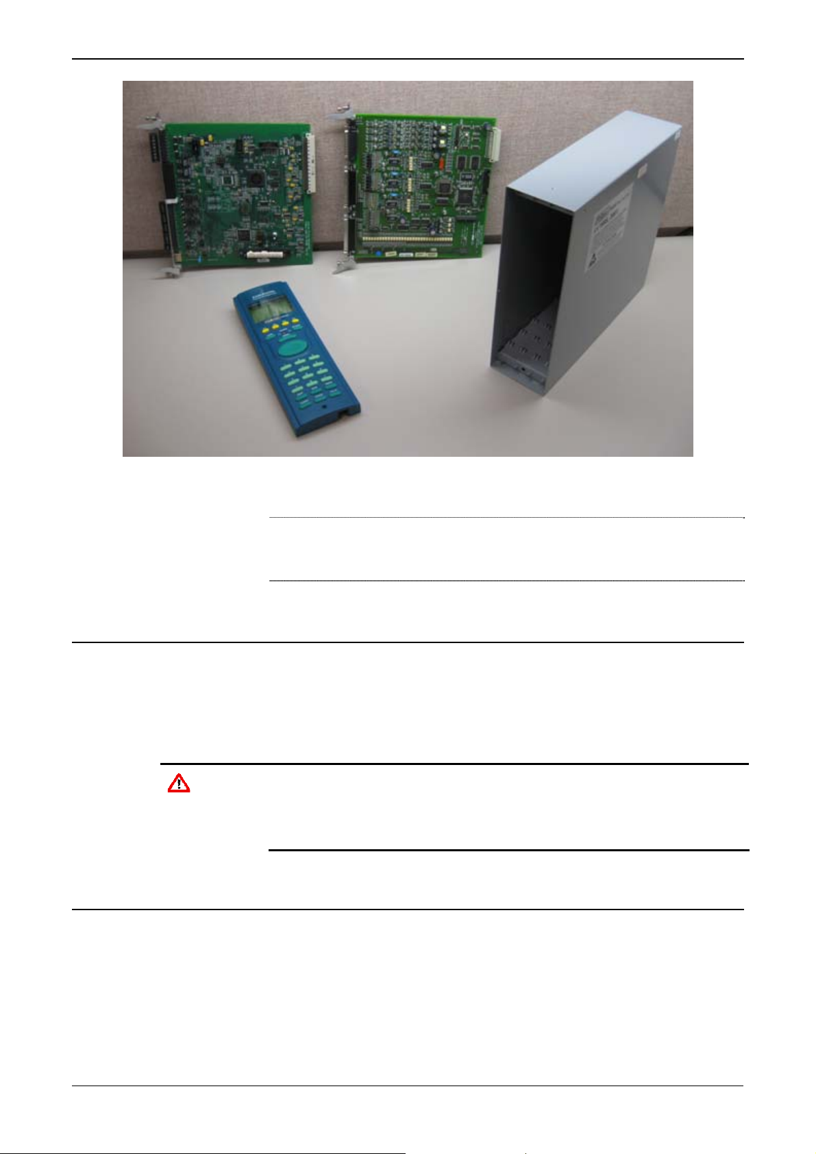
Figure 1-1. The FloBoss S600+ Flow Computer
The FloBoss S600+ Flow Computer is a panel-mount flow computer
designed specifically to measure hydrocarbon liquid and gas where
versatility and accuracy matter. The standard features of the S600+
make it ideal for fiscal measurement, custody transfer, batch loading,
and meter proving applications. The S600+ allows you to configure
multi-stream, multi-station applications, enabling you to
simultaneously meter liquids and gasses.
The S600+ is designed for use either as a stand-alone flow computer or
as a system component. The intelligent I/O modules fit both gas and
liquid applications and typically support two dual-pulsed streams and a
header. Adding I/O modules (up to a maximum of three) allows you to
configure up to six dual-pulsed streams or up to 10 single-pulsed
streams and two headers. The S600+ supports orifice, ultrasonic,
turbine, positive displacement, Coriolis, Annubar, and V-Cone® flow
1-2 General Information Revised Mar-11
Page 9

S600+ Instruction Manual
meter types and master meter, small volume compact, and pipe (both
bi-directional and uni-directional) proving methods.
The S600+ offers a variety of communication interfaces:
Two LAN ports (on the enhanced CPU module) for Ethernet
10Base-T or 100Base-T full-duplex connectivity (using either
Modbus TCP or Modbus over Ethernet protocols).
Note: The Ethernet module (P190), which provided an additional
Ethernet port for previous versions of the S600, is not
compatible with the S600+.
HART® communication using up to two 12-channel HART
modules, each of which supports point-to-point and multi-drop
architectures for up to 50 transmitters.
An embedded webserver allows remote access to the flow
computer. Security is provided using user name and password
protection with a detailed event log for audit purposes (supports
Windows® Internet Explorer® Version 5 or greater).
Two configurable EIA-232 (RS-232) serial ports.
Three EIA-422/485 (RS-422/RS-485) serial ports (supporting up to
57,600 bps baud) and up to four EIA-485 (RS-485) 2-wire serial
ports (supporting up to 57,600 baud rate) for connection to
intelligent meters, Modbus SCADA data networks, DCS
supervisory systems, and so on.
One dedicated configuration port (located on the bottom of front
display panel) for connection to the Config600 configuration
software.
Additional communications interfaces include:
• Serial Q.Sonic®
• Serial printer
• Serial or Modbus TCP Daniel chromatograph via Modbus
• Serial peer-to-peer
• Modbus EFM protocol, Modbus RTU, Modbus ASCII, Modbus
over Ethernet, and Modbus TCP
Miscellaneous interfaces which can operate via serial or Modbus
TCP:
Daniel liquid ultrasonic
Daniel gas ultrasonic
Sick ultrasonic
Daniel chromatograph
Note: All ports can connect to DCS systems, ultrasonic meters,
Coriolis meters, and so on.
Revised Mar-11 General Information 1-3
Page 10
S600+ Instruction Manual
The S600+ uses distributed processing to achieve maximum
performance. The CPU module incorporates a hardware floating point
processor. Each additional module also has local processing to convert
inputs and output from engineering units to field values and vice-versa,
as well as running background tests and PID loops.
The firmware uses 64-bit (double) precision floating point numbers for
the highest accuracy when performing all metering calculations.
Cumulative totals are stored in three separate memory locations (Trireg format) for maximum integrity. The user language LogiCalc™ also
allows you to perform logical control and double-precision
mathematical functions on the database objects.
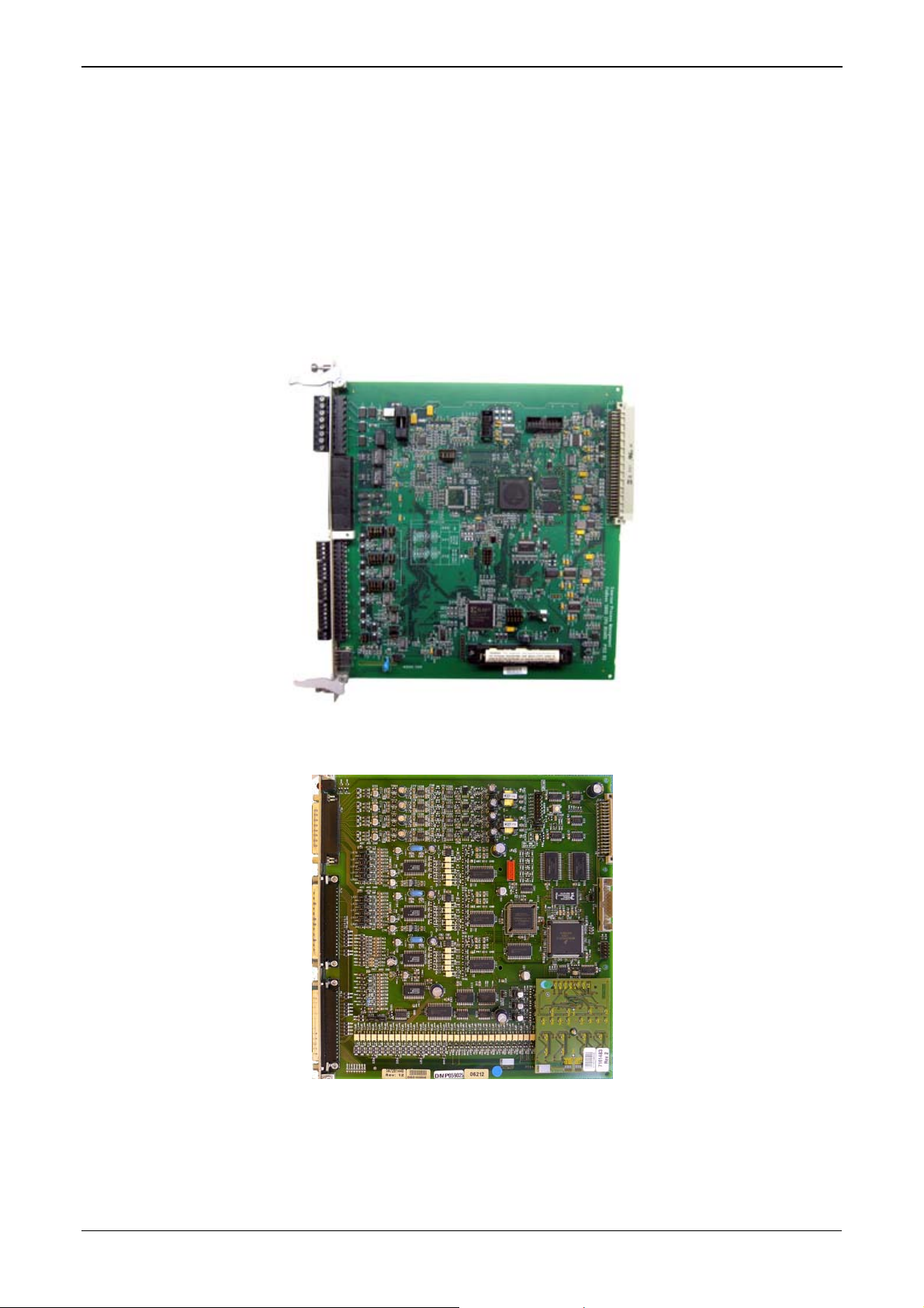
Figure 1-2. CPU Module
Figure 1-3. Intelligent I/O Module
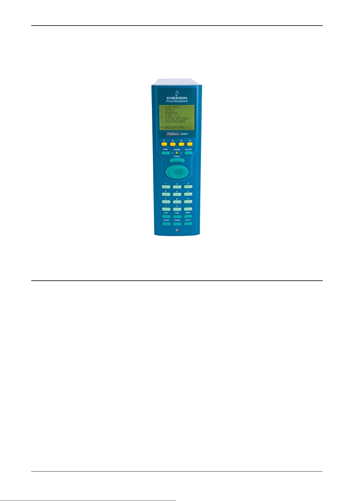
Front Display
Panel
The S600+’s front panel interface enables you to manage an existing
configuration or create a configuration using the PC-based Config600
configuration software.
1-4 General Information Revised Mar-11
Page 11
S600+ Instruction Manual
A communications port on the bottom of the panel provides a way to
directly connect to a PC. The front panel interface consists of a backlit
LCD display, a 29-button keypad, and an alarm status LED (see Figure
1-4).
Figure 1-4. Front Display Panel
1.3 Config600™ Configuration Software
Using Config600, you can both send (upload) new or modified
configurations to the S600+ and receive (download) existing
configurations from the S600+. You can also define the following
functions:
Stream and station totalisation.
Batch totalisation and correction.
Three-term PID control.
Flow balancing.
Flow scheduling.
Automatic proving sequence.
K-factor or meter factor linearisation.
Valve monitor/control.
Sampler control.
Station densitometer.
Station gas chromatograph.
Forward, reverse, and premium error totals.
Comprehensive maintenance mode.
Revised Mar-11 General Information 1-5
Page 12

S600+ Instruction Manual
Reporting.
Modbus.
Modify display matrix.
Config600 is a suite of software editors that enables you to monitor,
configure, and calibrate the S600+. The software comes in three
versions – Config600 Lite, Config600 Lite+, and Config600 Pro – with
Config600 Pro being the most powerful version.
Note: The S600+ does not operate until you send a configuration to it
from the host PC.
IPL600
Remote Automation Solutions provides a separate utility program
called “Interactive Program Loader 600” (or “IPL600”).
Using IPL600 and an IP or a dedicated serial port connection between
a host PC and an S600+, you can transfer and receive configuration
files (reports, Modbus configuations, customised displays, and
LogiCalc programs). While included as the Config Transfer utility in
Config600, IPL 600 has a standalone use for situations when you do
not need the full functionality of Config600. Details on using Config
Transfer/IPL600 are provided in the Config600 Software
Configuration User Manual (A6169).
1.3.1 Config600 Lite
Use the Config600 Lite software editor suite to modify pre-developed
configurations, transfer existing configurations, edit items on the front
panel display, and customise reports.
Note: You typically use Config600 Lite to custom-configure a new
With Config600 Lite you can:
S600+ during installation.
Edit process configuration data, including orifice size, analog input
scaling, alarm limits, and keypad values.
Build and customise Modbus slave maps, Modbus master polling
sequences, front panel displays, and period report formats.
Customise the alarm system, including alarm groups, suppression,
and inhibits.
Configure system security by setting user names and passwords,
and assigning access levels for each data object on the displays.
Specify the engineering units and totalisation rollover value.
Reflash the CPU module firmware with software upgrades and
transfer configurations via the Config Transfer utility (IPL600).
1.3.2 Config600 Lite+
The Config600 Lite+ software editor suite provides all the
functionality of the Config600 Lite suite, but adds the ability to create
a configuration file.
1-6 General Information Revised Mar-11
Page 13

With Config600 Lite+ you can:
Create a new application from base templates for gas, liquid, and
prover applications.
Edit process configuration data, including orifice size, analog input
scaling, alarm limits, and keypad values.
Build and customise Modbus slave maps, Modbus master polling
sequences, front panel displays, and period report formats.
Customise the alarm system, including alarm groups, suppression,
and inhibits.
Configure system security by setting user names and passwords,
and assigning access levels for each data object on the displays.
Specify the engineering units and totalisation rollover value.
Reflash the CPU module firmware with software upgrades and
transfer configurations via the Config Transfer utility (IPL600).
1.3.3 Config600 Pro
S600+ Instruction Manual
Use the Config600 Pro software editor suite to create new
configurations, modify existing configurations, transfer existing
configurations, edit items on the front panel display, and edit custom
reports.
With Config600 Pro you can:
Create a new application from base templates for gas, liquid, and
prover applications.
Edit process configuration data, including orifice size, analog input
scaling, alarm limits, and keypad values.
Build and customise Modbus slave maps, Modbus master polling
sequences, front panel displays, and period report formats.
Specify the engineering units and totalisation rollover value.
Customise the alarm system, including alarm groups, suppression,
text, and inhibits.
Configure system security by setting user names and passwords,
and assigning access levels for each data object.
Add and remove objects from the database.
Program special features using LogiCalc.
Reflash the CPU module firmware with software upgrades and
transfer configurations via the Config Transfer utility (IPL600).
Note: To obtain a Config600 Pro licence you must first attend and
successfully complete a training course.
Revised Mar-11 General Information 1-7
Page 14

S600+ Instruction Manual
1.4 Additional Technical Information
Refer to the following technical documents (available at
www.EmersonProcess.com/Remote) for additional and most-current
information.
Table 1-1. Related Technical Information
Name Form Number Part Number
FloBoss™ S600+ Flow Computer S600 D301151X412
Config600™ Configuration Software Config600 D301164X012
Config600™ Configuration Software User Manual A6169 D301220X412
1.4.1 Open Source Software
The FloBoss S600+ contains open source software covered by the
GPL, GPL2, GPL3, LGPL, OpenSSL, SSLeay, zlib, libzip2, and
Apache open source software licenses. The specific software being
used is U-Boot, the Linux kernel, glibc, Apache web server, mod_sll,
mod_alias, mod_rewrite, OpenSSL, BusyBox, ntpclient, tar32, and
JFFS2. These licenses are contained on the S600+ Open Source
Software CD (part number S600SRCOPEN). Source code is available
upon request. You may obtain a copy of this source code by contacting
Remote Automation Solutions Technical Support via SupportNet. This
product includes software developed by the OpenSSL Project for use
in the OpenSSL Toolkit (http://www.openssl.org). This product
includes cryptographic software written by Eric Young
(eay@cryptsoft.com).
1-8 General Information Revised Mar-11
Page 15
Chapter 2 – Installation
This chapter provides instructions on installing the S600+, including
installation preparation, procedures for panel-mounting, the installation
and removal of plug-in modules, and electromagnetic compatibility
(EMC) considerations.
In This Chapter
2.1 Preparing for Installation.......................................................................2-1
2.2 Environmental Considerations..............................................................2-2
2.3 Required Tools for Installation..............................................................2-2
2.4 Installing the S600+..............................................................................2-3
2.4.1 Unpacking the S600+.............................................................2-3
2.4.2 Removing the Front Panel.....................................................2-3
2.4.3 Installing the Panel-Mounted Unit..........................................2-6
2.4.4 Reinstalling the Front Panel...................................................2-8
2.5 Installing and Removing Modules.........................................................2-8
2.6 Installing EMC Protection...................................................................2-10
Caution
Failure to exercise proper electrostatic discharge precautions (such as
wearing a grounded wrist strap) when accessing the back of the unit or
when handling CPU or I/O modules may reset the processor or damage
electronic components, resulting in interrupted operations.
S600+ Instruction Manual
2.1 Preparing for Installation
The S600+ installation must conform to all applicable local codes and
regulations. All installation procedures should be in accordance with
normal practices of good workmanship. Although the S600+ shipped
to you may not include all of the hardware options described in this
manual, the procedure for the basic installation of the unit remains the
same.
Note: We strongly recommend you familiarize yourself with the
procedures described in this chapter before you begin to install
the S600+.
The S600+ uses a modular design that provides maximum flexibility
and ease of installation. The basic panel-mounted version consists of
three major components:
Fabricated metal case, complete with pre-installed PSU/backplane
and four card slots for the modules (a dedicated CPU slot and three
I/O slots).
Removable front panel comprising the LCD display and keypad
assembly.
Plug-in modules. A CPU module and one I/O module are supplied
for a basic configuration; two blank plates are supplied to cover the
unused slots.
Figure 2-1 shows the S600+ system components.
Revised Mar-11 Installation 2-1
Page 16
S600+ Instruction Manual
Figure 2-1. FloBoss S600+ System Components
Note: User-supplied tools to assist in the installation process may
include a Phillips screwdriver, a regular screwdriver, a small
adjustable spanner wrench, and a 2.5mm Allen key.
2.2 Environmental Considerations
The S600+ panel mounted flow computer is designed for use within
the control room. Place it in a position that provides ease of use,
comfort, and safety for operators and maintenance personnel. The
optimum height for viewing and using the display and keypad is at
operator eye level.
Caution
If you install one or more units in a confined space with other heatproducing equipment, give special attention to the combined heating
effect. This combined heat could increase the environmental
temperature beyond its acceptable threshold, thereby impacting
performance.
2.3 Required Tools for Installation
Before you attempt to install the S600+, ensure that you have the
following tools:
Small flat-blade screwdriver suitable for the slot-headed captive
screws on the rear of the case that secure each plug-in board into
the case.
5.5 mm (5 BA) hex or small adjustable wrench for the front panel
bosses.
2-2 Installation Revised Mar-11
Page 17
2.5 mm Allen key suitable for the hex cap screw on the front face
of the front panel that secures the front panel molding to the case.
2.4 Installing the S600+
Refer to the following procedures for installing the various S600+
components, including the front panel, panel-mounted unit, and
modules.
2.4.1 Unpacking the S600+
Unpack the S600+ carefully and inspect parts for visual damage.
Note: Do not discard packaging material until after you have
2.4.2 Removing the Front Panel
S600+ Instruction Manual
identified all pieces of the shipment and you are confident that
all parts are working correctly.
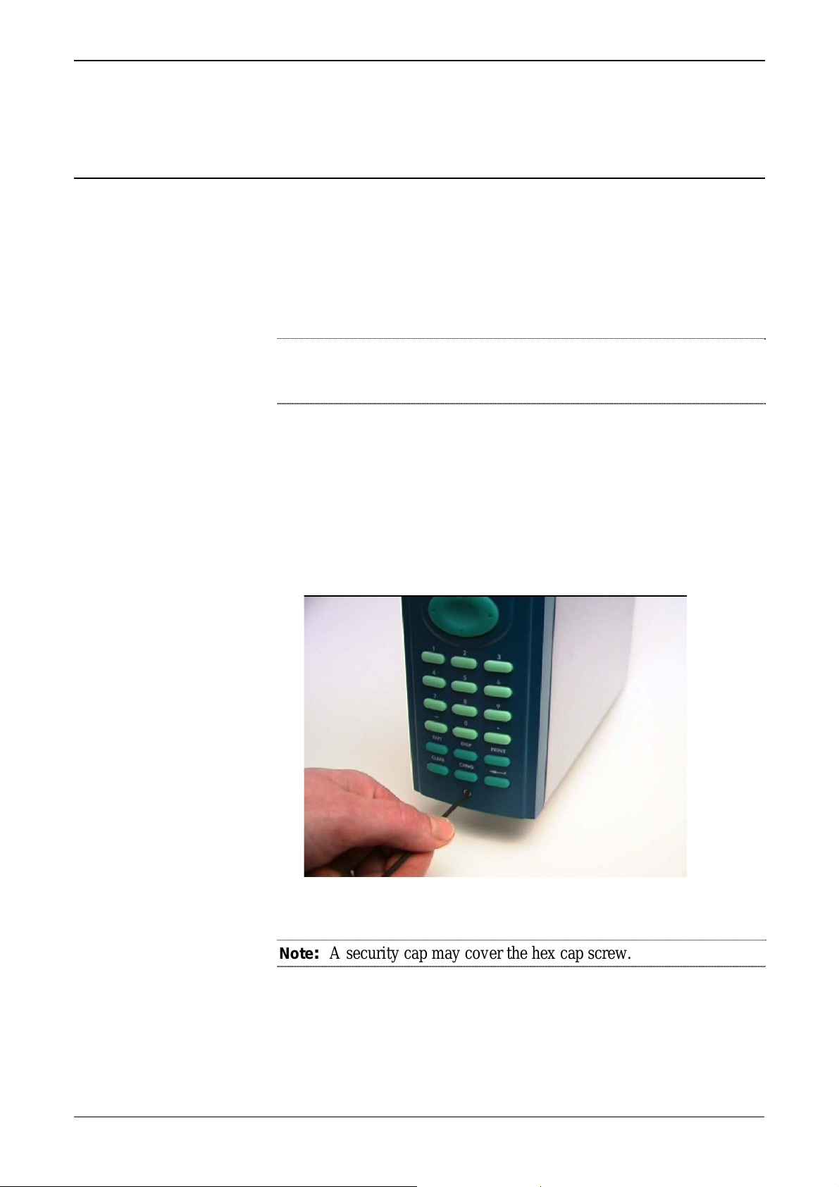
To begin the mounting process, remove the front panel from the
S600+:
1. Ensure power has been removed from the S600+.
2. Using a 2.5 mm Allen key, remove the hex cap screw from the
bottom centre of the front panel (refer to Figure 2-2).
Figure 2-2. Removing the Front Panel
Note: A security cap may cover the hex cap screw.
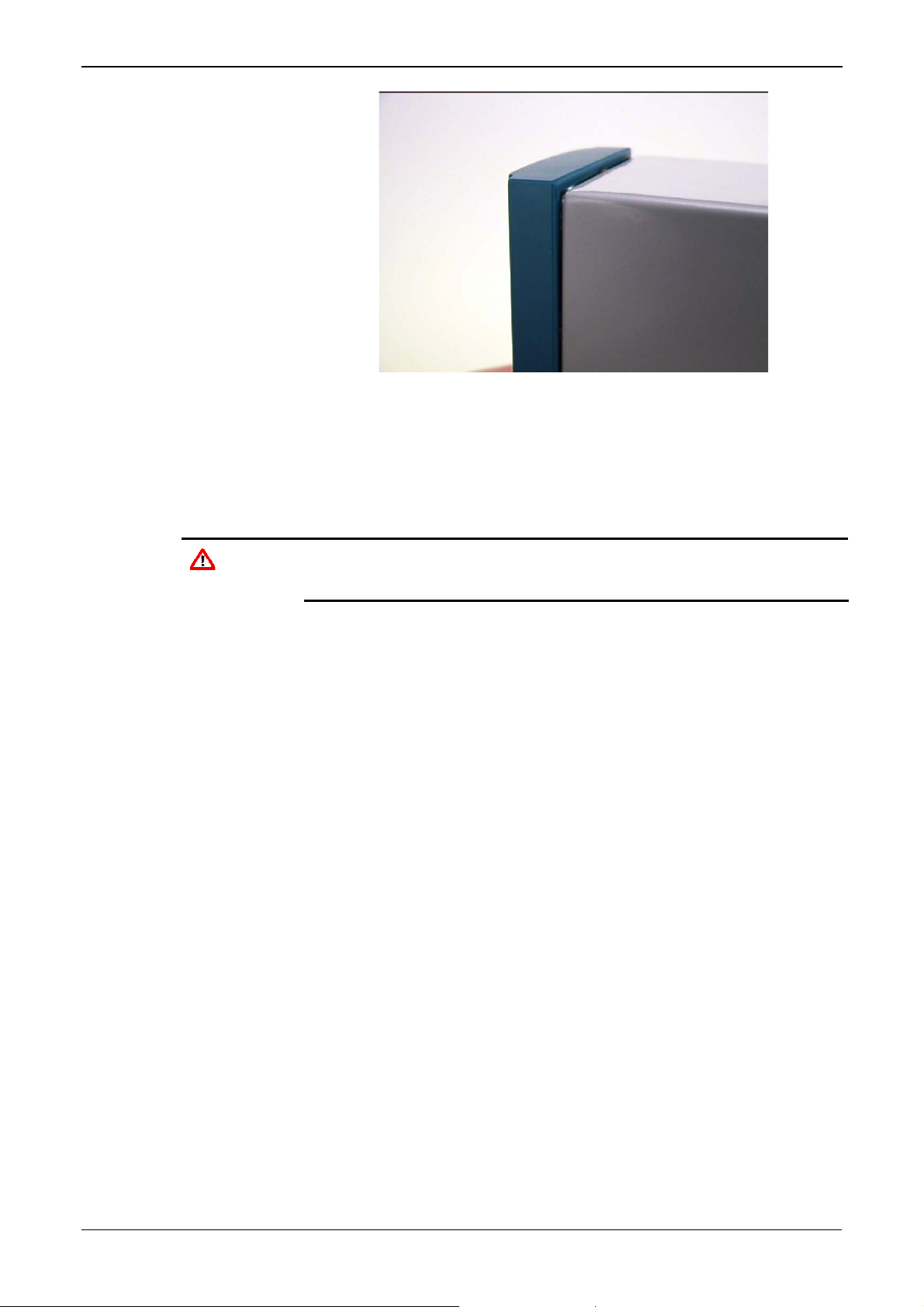
3. Carefully slide the front panel up 4 mm (0.15 in) to allow it to clear
the retaining groove at the top of the case, and then allow the panel
to come forward to clear the panel case completely (refer to Figure
2-3).
Revised Mar-11 Installation 2-3
Page 18
S600+ Instruction Manual
Caution
Figure 2-3. Lifted Front Panel
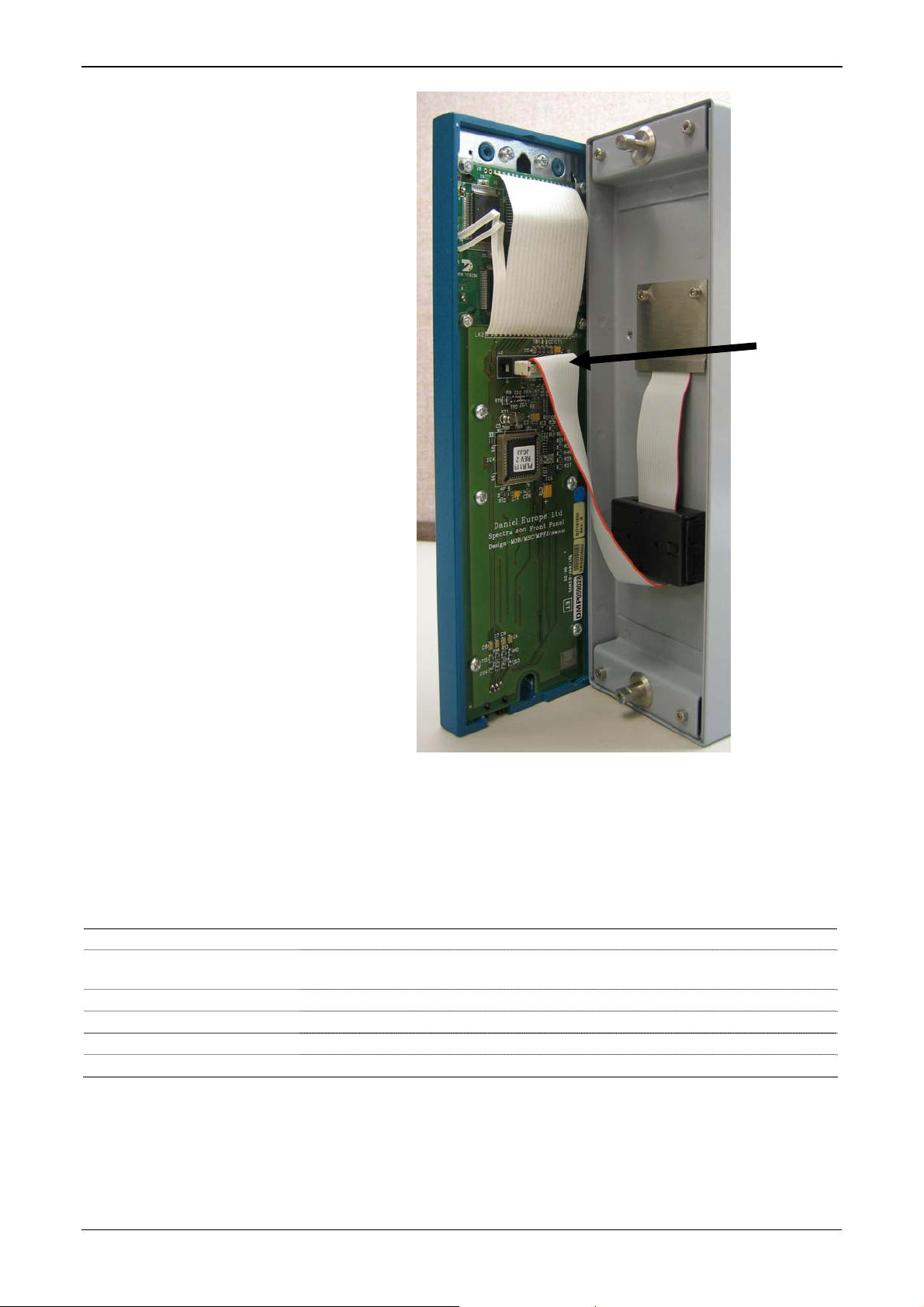
4. Disconnect the ribbon cable from the back of the front panel at the
blue connector (refer to Figure 2-4). Observe the orientation of the
connector with its mating keyway. You must correctly re-insert the
ribbon cable at the end of the installation process.
Do not remove the ribbon cable from the S600+ housing. This might
damage the S600+. Also, the ribbon cable may also have an EMC
clamp. Be sure to leave it intact without damaging the ribbon cable.
2-4 Installation Revised Mar-11
Page 19
S600+ Instruction Manual
Disconnect
Here
Figure 2-4. Remove Connector
5. Remove the top and bottom bosses from the unit housing, using a
5.5 mm (5 BA) hex wrench.
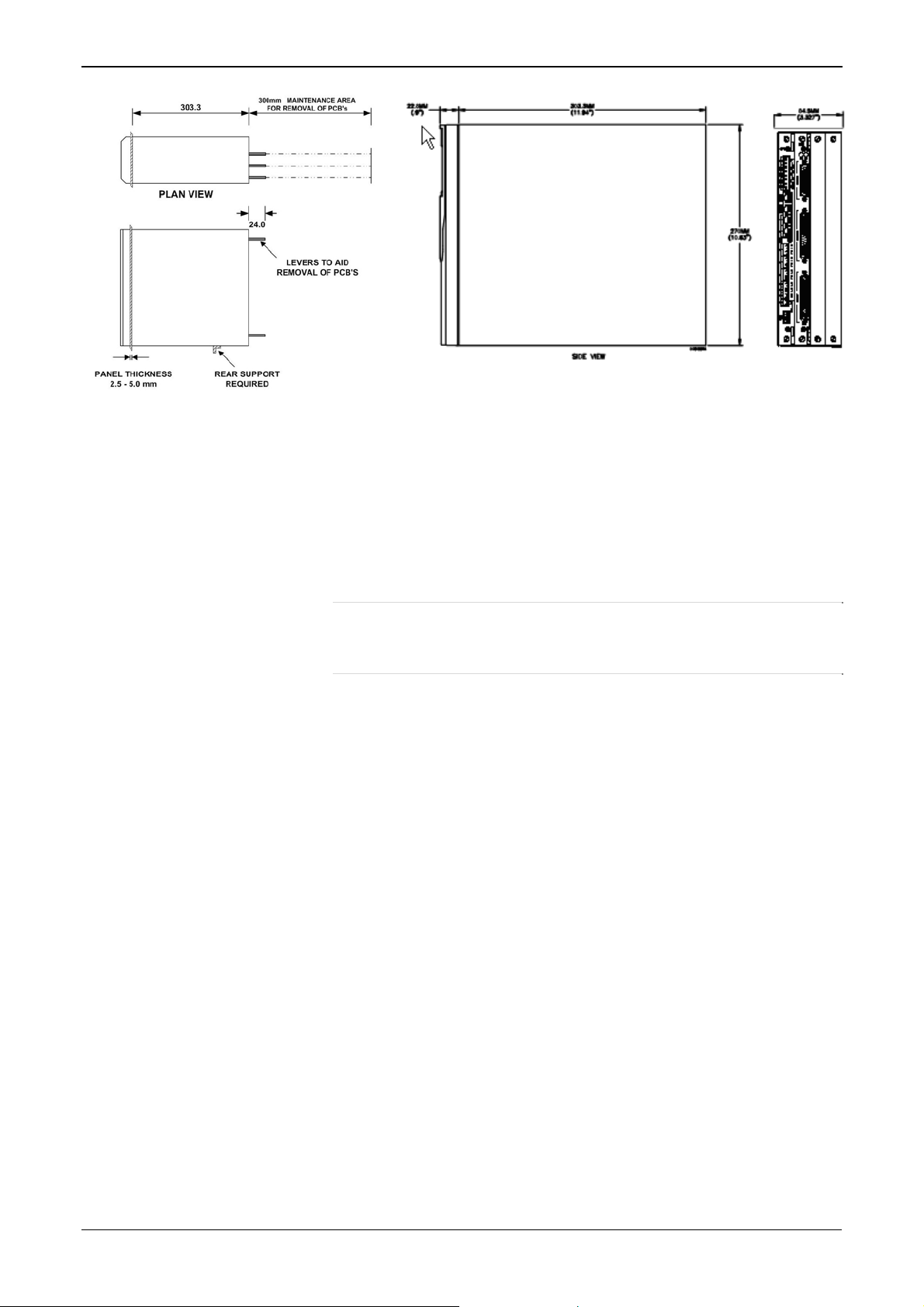
Table 2-1. Mounting Dimensions
Part Dimensions
Display Keypad Molding 85 mm (3.35") width x 269 mm (10.59") height x 28 mm (1.10") deep
Case
Panel Cutout 66 mm (2.6") width x 150 mm (5.9") height
Pitch Between Cases 110 mm (4.33") giving 25 mm (0.98") air gap
Max Panel Thickness 10 mm (0.39")
Access Allow 300 mm (11.81") clearance directly behind case for maintenance
84.5 mm (3.327") width x 270 mm (10.63") height x 303.8 mm (11.94")
deep
Revised Mar-11 Installation 2-5
Page 20
S600+ Instruction Manual
2.4.3 Installing the Panel-Mounted Unit
Figure 2-5. Panel Mount Dimensions
After removing the front panel, install the panel-mounted unit:
1. Keeping environmental considerations in mind, construct the
framework of the cubicle to support the operating panel.
Note: A standard 483 mm (19 in) rack that is 311 mm (12.25 in)
high can accommodate up to four S600+s provided you
support the rear of the case.
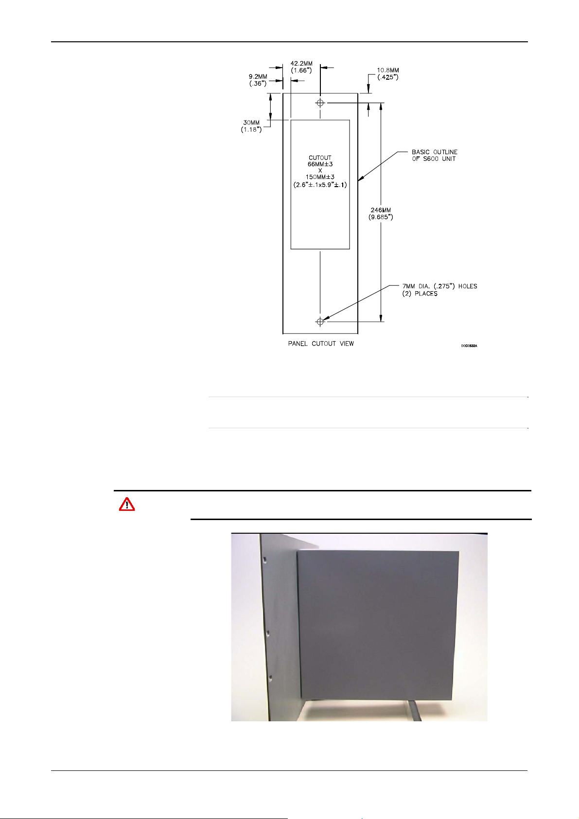
2. Refer to Figure 2-6 and Table 2-1 for position details for two 7 mm
(0.276 in) holes and a cutout. The panel cutout should be
rectangular for each S600+. Allow a tolerance of ± 3 mm (0.12 in)
on each axis.
2-6 Installation Revised Mar-11
Page 21
S600+ Instruction Manual
Caution
Figure 2-6. Panel Cutout Dimensions
Note: The S600+ fits into existing S500 and 869 flow computer
panel cutouts.
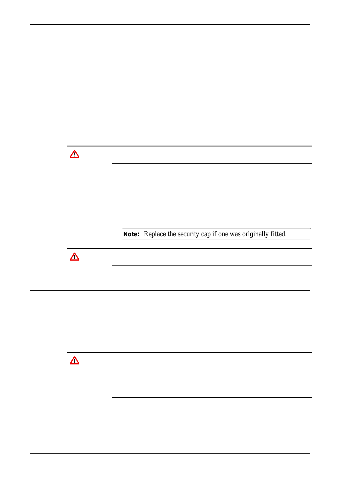
3. Ensure a panel thickness of at least 3 mm (0.12 in) to prevent
distortion. If you use a thinner panel, support the rear of the case
(refer to Figure 2-7).
Always use a rear support or anchor to prevent twisting and other
distortion effects during installation and maintenance.
Figure 2-7. Panel Mount Support
Revised Mar-11 Installation 2-7
Page 22
S600+ Instruction Manual
2.4.4 Reinstalling the Front Panel
Caution
4. Place the front of the case against the rear of the prepared cutout.
5. Re-install the top and bottom bosses and tighten with a 5.5 mm (5
BA) hex wrench.
6. Once you have fitted the rear support, use a self-tapping screw to
secure the case to the rear support. The maximum depth of the
screw inside the case should be 3 mm (0.12 in).
Re-installing the front panel is the final stage of the installation
process:
1. Connect the ribbon cable to the front panel.
Note how the connector fits into the keyway. You must insert the
ribbon cable correctly. Do not force the connector into the keyway.
2. Place the top of the front panel over the retaining groove on the top
boss and slide the front panel downwards.
3. Secure the front panel by placing the hex cap screw into its recess
in the bottom centre of the front panel.
4. Using a 2.5 mm Allen key, tighten the screw finger-tight. Turn an
additional 180 degrees clockwise to complete the installation.
Note: Replace the security cap if one was originally fitted.
Caution
Do not over-tighten the screw. Over-tightening will damage the panel
face.
2.5 Installing and Removing Modules
The S600+ ships with the CPU and I/O modules already installed.
Follow this procedure if you need to remove the modules for
maintenance or upgrade purposes.
The CPU module is located in the left-most rear slot of the case. You
can insert I/O modules in the remaining slots or leave them empty.
Cover any empty slots with the blank cover plates.
Caution
Removal
Take suitable electrostatic discharge precautions before you remove
any of the modules.
The terminals on some modules may be wired to electrical potentials
sufficiently high to cause electrical shock and injury. Turn off and
discharge any power sources for connected devices before you
perform any installation or repair work.
To remove a module:
1. Power down the S600+ before you attempt to extract a module.
2. Unscrew the retention screws before you attempt to remove a
module. This avoids damage to the ejectors (refer to Figure 2-8).
2-8 Installation Revised Mar-11
Page 23

Ejectors
S600+ Instruction Manual
Figure 2-8. Unscrewing the Retention Screws
3. Unlatch the ejectors for the appropriate module and pull the
module clear of the case. You may need to rock the module slightly
to release it from its connectors (refer to Figures 2-9 and 2-10).
Figure 2-9. Using the Ejectors
Revised Mar-11 Installation 2-9
Page 24
S600+ Instruction Manual
Figure 2-10. Module Ready for Removal or Insertion
Installation
To install a module:
1. Carefully align the module with the guides (located at the top and
bottom of the case). Gently slide the module into the case until it
seats fully with the appropriate connector on the backplane.
2. Press each of the two ejectors securely into place once the module
is fully inserted.
Caution
Inserting and seating a module along the guides does not require
excessive force. Take care not to twist or otherwise distort the module
during the installation.
3. Secure the module with the retention screws (two per board).
2.6 Installing EMC Protection
Your site may require you to install electromagnetic compatibility
(EMC) shielding on the S600+ to minimize electromagnetic
interference. The S600+ EMC protection kit (which came with your
S600+) typically has the following components:
1 security backplate (place over the installed modules)
1 25-way EMISTOP Inline T Filter Adaptor (attach to the 25-pin
socket A on the I/O module)
1 37-way EMISTOP Inline T Filter Adaptor (attach to the 37-pin
socket B on the I/O module)
3 large (for 13mm cable) ferrite clamps
3 medium (for 10mm cables) ferrite clamps
1 small (for 6.5mm cables) ferrite clamp
2-10 Installation Revised Mar-11
Page 25
S600+ Instruction Manual
2 M3 x 6mm screws (which secure the EMC backplate to the sides
of the S600+ housing)
5 TY523 Ty-Rap self-locking cable fasteners (use as necessary to
secure cables)
Note: These are standard components for a standard configuration. If
your S600+ has a different configuration (for example,
additional modules), you may have more components.
Install the EMC kit after you install the S600+ but before you wire the
modules.
To install the EMC components:
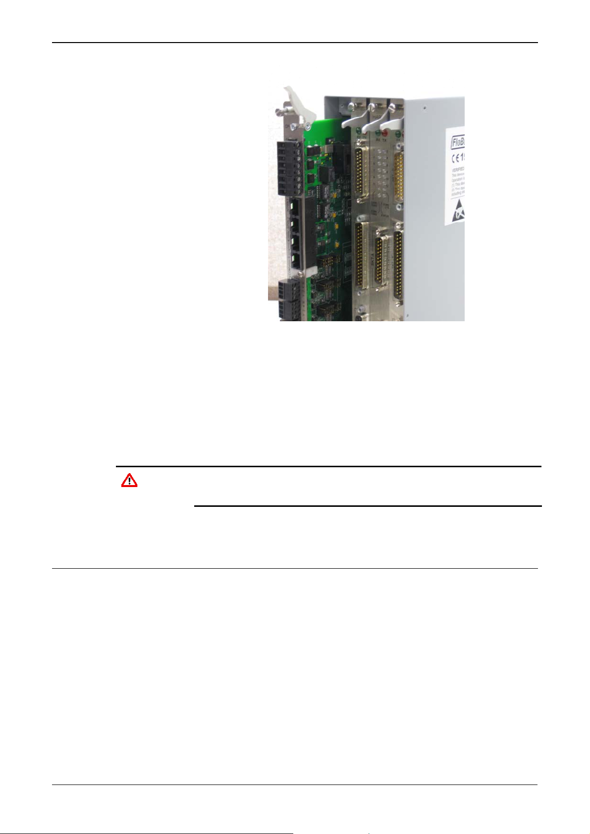
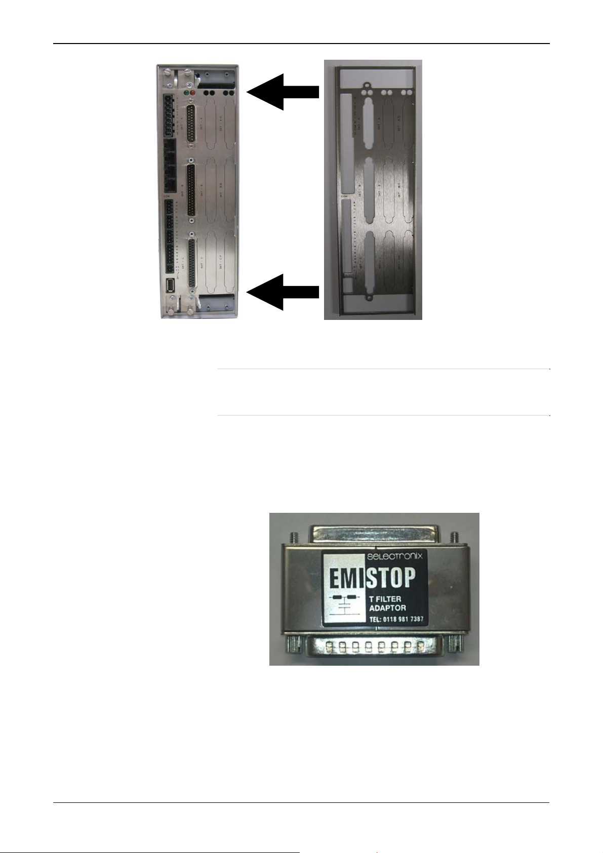
1. Unscrew and remove the small Phillips-head screws on the I/O
module (see Figure 2-11).
Remove screws
Figure 2-11. Screws on I/O Module
2. Place the security backplate over the modules already installed in
the S600+ and secure the backplate to the I/O module using the two
screws you removed in step 1 (see Figure 2-12).
Revised Mar-11 Installation 2-11
Page 26
S600+ Instruction Manual
Figure 2-12. Security Backplate in Place
Note: In actual operation, the two right-most slots on the S600+
shown in Figure 2-12 would either contain modules or
would be covered by blanking plates.
3. Secure the backplate to the sides of the S600+ housing using the 2
M3 x 6mm screws.
4. Place and secure the 25-way and 37-way EMISTOP adaptors (see
Figure 2-13) onto, respectively, sockets A and B on the I/O module
(see Figure 2-14).
Figure 2-13. EMISTOP Connector
5. Wire the modules according to your site’s requirements.
6. Attach a small ferrite clamp onto the wiring to socket A on the I/O
module. Attach large ferrite clamps onto the cables to sockets B
and C (see Figure 2-14).
2-12 Installation Revised Mar-11
Page 27
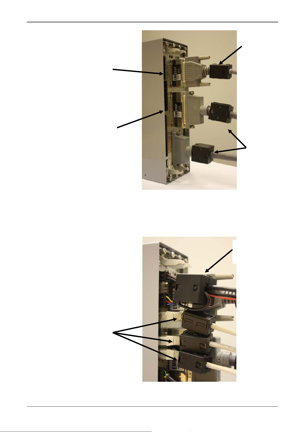
25-way
EMISTOP
37-way
EMISTOP
S600+ Instruction Manual
Medium
ferrite
clamp
Large
ferrite
clamps
Figure 2-14. Clamps on I/O Module Wiring
7. Attach a large ferrite clamp onto the wiring to the CPU’s power
connections and one medium clamp to the COM3 and COM 4
connections (see Figure 2-15).
Large
ferrite
clamp
Medium
ferrite
clamps
Figure 2-15. Clamps on CPU Module Power & COM Connections
Revised Mar-11 Installation 2-13
Page 28
S600+ Instruction Manual
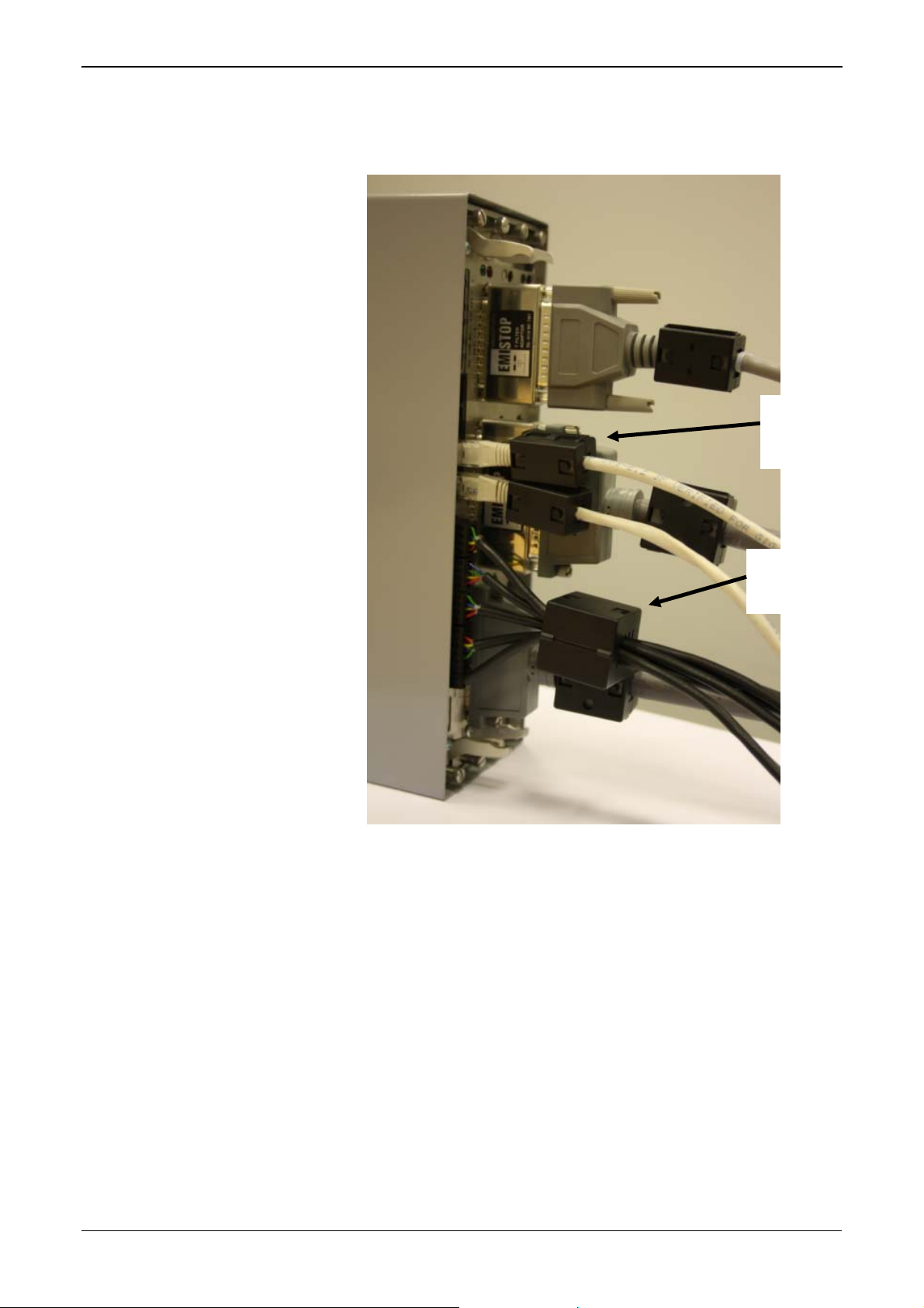
8. Attach a medium ferrite clamp onto the wiring for COMs 5, 6, and
7 and a small ferrite clamp onto the Ethernet cable (see Figure 2-
16).
Small
ferrite
clamp
Medium
ferrite
clamp
Figure 2-16. Clamps on CPU Module COM and Ethernet Connections
This completes the installation process and provides the S600+ with
EMC protection.
2-14 Installation Revised Mar-11
Page 29
Chapter 3 – CPU Module
This chapter provides information on the power and communication
connections for the CPU module.
In This Chapter
3.1 CPU Module (P152)............................................................................3-1
3.2 Power Supply......................................................................................3-4
3.2.1 Watchdog Relay ....................................................................3-4
3.2.2 On-Board Battery Backup......................................................3-4
3.3 Communication Ports .........................................................................3-5
3.3.1 EIA-232 (RS-232) Serial Port................................................3-6
3.3.2 EIA-422 (RS-422)/EIA-485 (RS-485) Multi-drop Port............3-7
3.3.3 Ethernet LAN Ports................................................................3-7
3.3.4 Local Operator PC or Remote Display Port ..........................3-7
3.4 CPU Connectors and Jumpers...........................................................3-8
3.5 USB Port.............................................................................................3-9
3.6 Additional Technical Information ........................................................3-9
Caution
Failure to exercise proper electrostatic discharge precautions (such as
wearing a grounded wrist strap) when accessing the back of the unit or
when handling CPU or I/O modules may reset the processor or damage
electronic components, resulting in interrupted operations.
S600+ Instruction Manual
3.1 CPU Module (P152)
The CPU module contains the host processor and associated
peripherals, which form the heart of the S600+ system. Various plug-in
connections are provided on the rear backplate of the CPU module.
Refer to Figure 3-1 for an illustration of the CPU module backplate
and to Figure 3-2 for a schematic of the CPU power terminations.
Figure 3-3 shows the wiring terminations. Additionally, the module
uses connectors and jumpers, which are set at the factory prior to
shipping. See Section 3.5, Jumpers for further information.
It is recommended that all wiring be made with stranded wire that is no
larger than 1.5 mm
of 1.75 mm
Power wiring is recommended to be 1.5 mm2 (0.0023 in2). Observe all
local wiring practices and regulations.
Caution
Do not use a Mega or similar instrument to check for isolation or
continuity between signals on any of the S600+ connectors. These
instruments produce voltages far in excess of design parameters and
may damage the S600+ or its connectors.
2
2
to 1.65 mm2 (0.0027 in2 to 0.0025 in2) is recommended.
(0.0023 in2) For the communication ports, wiring
Revised Mar-11 CPU Module 3-1
Page 30
S600+ Instruction Manual
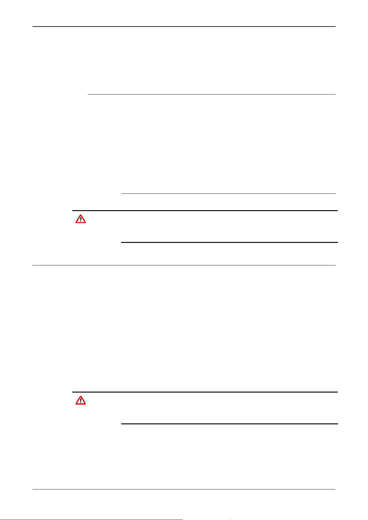
r
TB-1 Powe
First Ethernet port
Four additional RS-485
ports (COM 9 through
COM 4
COM 5
COM 6
COM 7
COM 12)
Second Ethernet port
COM 3
Note: You can configure
the A (–) terminal of COM
12 as a digital input
Ejector
latches
USB port
Figure 3-1. CPU Module Backplate
Backup
battery
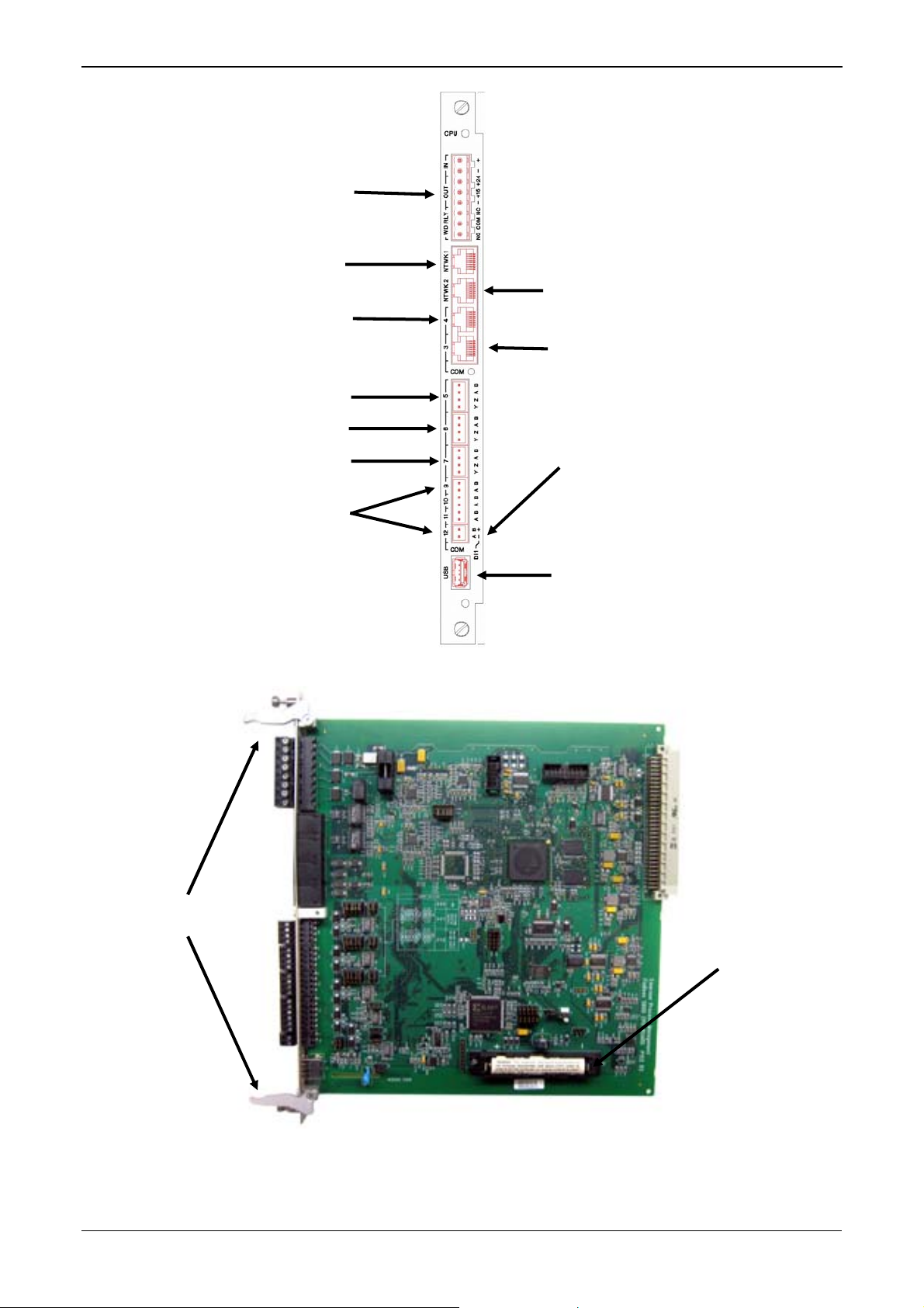
Figure 3-2. CPU Module
3-2 CPU Module Revised Mar-11
Page 31

CPU MODULE (P152)
S600+ Instruction Manual
SERVICE
SERVICE
SERVICE
SERVICE
SERVICE
1
2
3
4
5
6
7
8
ETHERNET
1
2
3
N/C
4
N/C
5
6
N/C
7
N/C
8
SERVICE
1
1
2
3
4
5
6
7
8
1
2
3
4
5
6
7
8
1
2
3
4
0V
ETHERNET
RS232
RS422/485
0V
RS422/485
RS232
RS422/485
RS485
RS485
USB
RS485
RS485
2
3
N/C
4
N/C
5
6
N/C
7
N/C
8
SERVICE
1
2
3
4
5
6
7
8
9
10
11
12
13
14
15
16
17
18
19
20
Figure 3-3. CPU Module Terminations
SERVICE
RESERVED FOR FRONT PANEL
AND CONFIG 600 COMMS
Figure 3-4. Front Panel Terminations
COMM - 1
RJ-12
RTS
TX
GND
GND
RX
CTS
P153 FRONT PANEL
1
2
3
4
5
6
PC SETUP
Revised Mar-11 CPU Module 3-3
Page 32

S600+ Instruction Manual
3.2 Power Supply
The power connection is a plug-in, standard 5 mm pitch screw terminal
block on the CPU module. The power supply connector is labeled TB-
1. Refer to Table 3-1 for the TB-1 pin connections.
Power the S600+ using a nominal 30 Volts dc power source capable of
supplying 2 Amps. The S600+ operates between 20 and 32 Volt dc.
The startup in-rush current may draw 6 amps for approximately 100
milliseconds. This in-rush becomes significant when multiple flow
computers are connected to the same power supply.
An on-board anti-surge fuse (2.5 Amp rating) protects the supply line
should a fault occur within the unit.
Fully regulated 15 and 24 Volts dc supplies are also available for
applications such as powering loops or pre-amplifiers. Resettable
thermal fuses protect these outputs.
Table 3-1. TB-1 Pin Connections (Power)
Pin Function
1 +24 V dc INPUT
2 0 V (Return) INPUT
3 +24 V dc OUTPUT (500 mA)
4 +15 V dc OUTPUT (100 mA)
5 0 V (Return) OUTPUT
3.2.1 Watchdog Relay
A single pole, double-throw relay with Normally Open or Normally
Closed terminals provides the watchdog status from pins 6, 7, and 8 of
TB-1. Table 3-2 shows the TB-1 pin connections. Connection is
through plug-in, standard 5 mm pitch screw terminals.
The relay is energized during normal operation. A CPU failure causes
the relay to de-energize.
Note: Contact is rated at 1 Amp, 30 Volts dc and 30 Volts ac, and is a
Form “C” contact.
Table 3-2. TB-1 Pin Connections (Watchdog Relay)
Pin Function
6 Normally Closed
7 Common
8 Normally Open
3.2.2 On-Board Battery Backup
The backup battery (see Figure 3-2) retains the contents of the SRAM
on the CPU module, the PC-compatible BIOS CMOS memory area,
and the calendar clock. The battery, a Lithium 3.0 volt 1500
mAmp/hour unit, is user-replaceable. For further battery specifications,
see the technical specification (S600). To ensure that the battery is
3-4 CPU Module Revised Mar-11
Page 33

S600+ Instruction Manual
fully functional, the S600+ software routinely performs a regular load
test on the unit.
Replacing the
Battery
To replace the backup battery on the CPU module:
Note: Before beginning this process, ensure that any critical processes
the S600+ controls are otherwise managed.
1. Power down the S600+.
2. Disconnect wiring from the CPU module.
Note: Remove the security backplate, if one is installed on the
S600+.
3. Unscrew the retention screws.
4. Unlatch the ejectors (see Figure 3-2) and pull the board clear of the
case.
5. Place the CPU module on a flat anti-static surface so that the
battery faces up (as shown in Figure 3-2).
6. Use a small screwdriver to carefully prise the battery out of its
holder.
Note: The CPU module is designed to hold sufficient charge to
7. Replace the battery with an exact duplicate (Lithium 3V 1500
mAh, part number S600+BATTERY).
8. Slide the CPU module back into the S600+ case, ensuring that it
seats firmly into its connectors.
9. Secure the retention screws.
Note: If appropriate, replace the EMC backplate.
10. Reconnect wiring and apply power to the S600+.
3.3 Communication Ports
The CPU has 12 standard communication ports: nine serial and two
Ethernet (see Figure 3-1). Table 3-3 details the communications ports.
COM 1-7
Comm ports 1 through 7 are essentially unchanged from previous
versions of the S600.
Comm ports 1 and 7 contain internal connections to other boards in the
S600+ which are not available for external host or local operator
communications. You can use Comm Port 3 or 4 to route Remote
Display connections. Comm 1 (located at the base of the faceplate) is
reserved for Config Transfer functions.
provide time (3-5 minutes) for you to replace the battery.
COM 9-12
Revised Mar-11 CPU Module 3-5
The S600+ adds four new RS-485 serial ports (COM 9 through COM
Page 34

S600+ Instruction Manual
12), located in the lower half of the CPU module (see Figure 3-1).
Table 3-3. Communication Ports
Communications Port Backplate Descriptor Description
Network 1 NTWK1 Ethernet
Network 2 NTWK2 Ethernet
Comm 4 COM4 EIA-232 (RS-232)
Comm 3 COM3 EIA-232 (RS-232)
Comm 5, 6 & 7 TB2, TB3, TB4 EIA-422 (RS-422) or EIA-485 (RS-485)
Comm 9 TB6
Comm 10 TB6
Comm 11 TB6
Comm 12 TB6
USB
For information on the communications port on the front panel which
can also act as Comm 2, refer to Chapter 5, Front Panel.
3.3.1 EIA-232 (RS-232) Serial Port
The CPU module’s backplate provides two EIA-232 (RS-232D)
communications ports labeled COM3 and COM4. The ports use FCC68 RJ-45 connectors. The COM3 and COM4 pin connections are
shown in Table 3-4. Figure 3-5 shows a sample pin connection.
Converters are commercially available to configure either 9-way D
type or 25-way D type connection. The ports support baud rates from
2400 to 57600 bps.
Table 3-4. COM3 and COM4 Pin Connections
Pin Function
1 GND
2 DTR
3 RTS
4 TX
5 RX
6 CTS
7 DSR
8 DCD
Figure 3-5. Pin Connections
3-6 CPU Module Revised Mar-11
Page 35

S600+ Instruction Manual
The maximum cable length is a function of the baud rate and quality of
cable used. For example, a maximum length of 15 m (50 ft) should be
used at 19200 bps when using unscreened cable.
Connect ports to the peripheral devices using multi-conductor, shielded
cable not longer than 8 meters (approx. 25 feet). We recommended
(especially in noisy environments) that you connect the cable screen to
protective earth to keep the signal ground separate.
3.3.2 EIA-422 (RS-422)/EIA-485 (RS-485) Multi-drop Port
The CPU module provides three EIA-422 (RS-422) or EIA-485 (RS-
485) ports, labeled COM5, COM6, and COM7. These provide high
speed/long distance links of up to 57600 bps and 1200 m (4000 ft). The
ports use the connector labeled TB-2. Table 3-5 shows the COM5,
COM6, and COM7 pin connections.
Note: Jumpers on the enhanced CPU module now provide RS-485
linking, so that wire linking is no longer necessary. If the cable
is already linked (as in an upgrade), you do not need to remove
the linked pairs.
Table 3-5. COM5, COM6, and COM7 Pin Connections
Channel Pin Function
COM5
COM6
COM7
3.3.3 Ethernet LAN Ports
The CPU module provides two Ethernet ports – NTWK1 and NTWK2
– for high-speed communications using an Ethernet Local Area
Network (LAN) architecture. The speed of data transfer is 100Mb full
duplex when using 100BASE-T twisted pair cable.
1 B
2 A
3 Z
4 Y
5 B
6 A
7 Z
8 Y
9 B
10 A
11 Z
12 Y
These ports use a FCC-68 RJ-45 connector. No hardware configuration
or wiring is required for these communications ports.
3.3.4 Local Operator PC or Remote Display Port
You can configure COM3 or COM4 to connect the S600+ to a remote
display or the host PC (COM2).
Use only shielded, multi-conductor cable to connect to the COM3-4
port. It is recommended—particularly in noisy environments—that you
Revised Mar-11 CPU Module 3-7
Page 36

S600+ Instruction Manual
connect the cable shield to earth ground to keep the signal ground
separate.
Connecting to
the S600+
You need a special serial cable to connect the host PC to the S600+. A
ready-made link cable (part number 3080017) is available for a PC
with a 9-pin serial port.
Alternatively, you may fabricate your own link cable using the wiring
details in Figure 3-65.
Note: Due to the high baud rate used for the communications between
the host PC and the S600+, restrict the maximum cable length
to 5 m (15 ft).
Figure 3-6. Link Cable
3.4 CPU Connectors and Jumpers
Table 3-6 shows the connectors and jumpers on the CPU module. This
information is for identification purposes only. Do not modify these
settings, unless told to do so by the factory.
Note: The position values shown in boldface are the default
configuration settings, which may not apply to your specific
configuration.
Table 3-6. CPU Jumpers
Jumper/Connector Description
P1 Back plane connector
P2 Cold start forced on power up
P3 Security jumper (Off – Level 1 security enabled)
P4 Debug console (factory use only)
P5 Processor programming header (factory use only)
P6 CPLD programming header (factory use only)
P7 Termination resistors for COM5 (1-2 side for ON)
3-8 CPU Module Revised Mar-11
Page 37

S600+ Instruction Manual
Jumper/Connector Description
P8 Termination resistors for COM6 (1-2 side for ON)
P9 Termination resistors for COM7 (1-2 side for ON)
P10
P11
P12
P13 Termination resistors for COM10 (1-2 ON)
P14 Termination resistors for COM9 (1-2 ON)
P15 Termination resistors for COM12 (1-2 ON)
P16
P17
P18 Termination resistors for COM11 (1-2 ON)
P20 Watchdog Jumper on 2-3 must be selected
P26 Flash write protect
P27 Flash boot selection (NAND/NOR)
RS-422/RS-485 selector for COM5.
1-2, 4-5, 7-8, 10-11 side for RS-422
Jumper 14-15 must always be fitted
RS-422/RS-485 selector for COM6.
1-2, 4-5, 7-8, 10-11 side for RS-422
Jumper 14-15 must always be fitted
RS-422/RS-485 selector for COM7.
1-2, 4-5, 7-8, 10-11 side for RS-422
Jumper 14-15 must always be fitted
TB6 serial port or digital input mode selector
1-2 and 3-4 for serial port
2-3 and 5-6 for digital input
3.5 USB Port
Use the 2.0 USB port on the CPU module to export alarm history,
event history, and report history information to a USB flash drive.
You access the export facility either through the S600+ front panel or
the webserver. Select Tech/Engineer > USB.
Note: For detailed instructions, see Chapter 5, Front Panel.
3.6 Additional Technical Information
Refer to the following technical documentation (available at
www.EmersonProcess.com/Remote) for additional and most-current
information.
Table 3-7. I/O Module Technical Specifications
Name Form Number Part Number
FloBoss™ S600+ Flow Computer S600 D301151X412
Revised Mar-11 CPU Module 3-9
Page 38

S600+ Instruction Manual
[This page is intentionally left blank.]
3-10 CPU Module Revised Mar-11
Page 39

Chapter 4 – Input/Output (I/O)
This chapter provides information on plug-in connector blocks and
field wiring (ANIN and PRT signals) for the I/O, Prover, and HART
modules. This chapter also discussed the optional pulse-counting
mezzanine module (P148) which fits as a daughterboard on either the
I/O or Prover module.
Caution
In This Chapter
Caution
Failure to exercise proper electrostatic discharge precautions (such as
wearing a grounded wrist strap) when accessing the back of the unit or
when handling CPU or I/O modules may reset the processor or damage
electronic components, resulting in interrupted operations
4.1 I/O Module (P144) ..............................................................................4-1
4.1.1 Analogue Inputs (ANIN)......................................................... 4-3
4.1.2 Analogue Outputs (DAC)....................................................... 4-5
4.1.3 Digital Inputs (DIGIN)............................................................. 4-6
4.1.4 Digital Outputs (DIGOUT)......................................................4-8
4.1.5 Turbine Pulse Inputs.............................................................. 4-9
4.1.6 Pulse Outputs (PULSEOUT) ...............................................4-10
4.1.7 Raw Pulse Output (RAWOUT) ............................................4-11
4.1.8 Frequency Inputs................................................................. 4-12
4.1.9 PRT/RTD Inputs ..................................................................4-13
4.1.10 Jumper Settings................................................................... 4-14
4.2 Prover Module (P154).......................................................................4-16
4.2.1 Digital Inputs (DIGIN)........................................................... 4-18
4.2.2 Digital Outputs (DIGOUT)....................................................4-20
4.2.3 Turbine Pulse Inputs............................................................ 4-21
4.2.4 Pulse Outputs (PULSEOUT) ...............................................4-22
4.2.5 Frequency Inputs................................................................. 4-22
4.2.6 Jumper Settings................................................................... 4-24
4.3 HART Module (P188) .......................................................................4-25
4.4 Mezzanine Module (P148)................................................................ 4-27
Perform all wiring with stranded wire no larger than 1.75mm
all local wiring practices and regulations.
Do not use a Mega or similar instrument to check for isolation or
continuity between signals on any of the S600+ connectors. These
instruments produce voltages far in excess of design parameters and
may damage the S600+.
S600+ Instruction Manual
2
. Observe
4.1 I/O Module (P144)
The I/O module (P144) measures process signals the CPU uses while
running the flow computer functions. The module provides 12
analogue inputs (AI), 4 analogue outputs (AO), 16 digital inputs (DI) ,
12 digital outputs (DO), 4 pulse inputs (PI), 5 pulse outputs (PO), 3
frequency (density) inputs, and 3 PRT/RTD inputs. Refer to Figure 4-2
for the I/O module terminations.
Revised Mar-11 I/O 4-1
Page 40

S600+ Instruction Manual
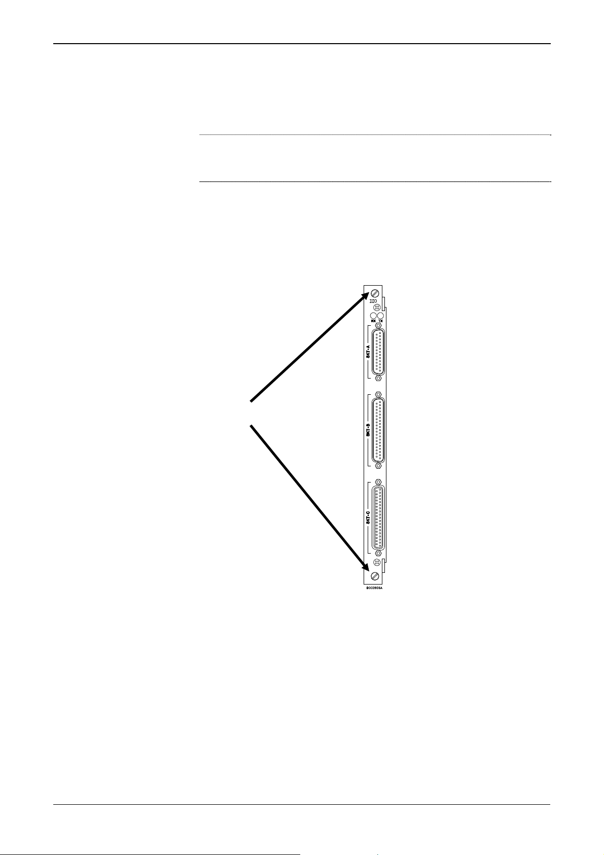
For field wiring, the module provides three low-density D-type
connectors: SKT-A, SKT-B, and SKT-C (refer to Figure 4-1).
SKT-A
ANIN 1-10
ANOUT 1-4
SKT-B
ANIN 11-12
DIGIN 1-6
DIGOUT 1-2
Freq Inputs
Pulse Outputs
Figure 4-1. I/O Module (P144)
SKT-C
DIGIN 7-16
DIGOUT 3-12
Turbine Inputs
Mezzanine
module (P148)
4-2 I/O Revised Mar-11
Page 41

S600+ Instruction Manual
Figure 4-2. Example I/O Module (with Mezzanine Module)
I/O MODULE (P144)
SERVICE
SERVICE
SERVICE
1
14
2
15
3
16
4
17
5
18
6
19
1mA
4
1
21
24
1mA
5
2
22
25
1mA
6
3
23
26
13
14
15
16
17
18
19
19
18
17
16
15
14
13
12
11
10
9
8
7
24
5
LK 29
LK 30
+15V
+15V
+15V
+15V
+12V
0-1 V
+12V
0-1 V
+12V
0-1 V
1 - 5 V
1 - 5 V
4 - 20 mA
10 K
10 K
10 K
HITHIT
8
21
9
22
10
20
11
24
12
25
13
23
8
7
20
30
31
32
33
35
34
12
9
27
10
28
11
29
36
37
37
36
35
34
33
32
31
30
29
28
27
26
25
4
23
3
22
2
21
1
20
SERVICE
SERVICE
SERVICE
Figure 4-3. I/O Module Terminations
4.1.1 Analogue Inputs (ANIN)
Each I/O module has
measuring five single-ended analogue input (ANIN) channels.
channel (ANIN 1-10) is configurable within a 0 to 5.25 volt or 0 to 22
Revised Mar-11 I/O 4-3
two fully floating A/D converters, each
Each
Page 42

S600+ Instruction Manual
Caution
mA input range. The module also provides two current-only inputs
(ANIN 11 and 12), for a total of 12 analogue inputs.
The primary measurement for ANIN 1-10 is voltage, which is
compared to a stable reference source. The channels are configu
rable
to current using a bit link (jumper) on the module to place a high
accuracy calibrated shunt resistor in parallel with the input. Refer
to
Figures 4-4 and 4-5.
Set the channels for each A/D converter to the same value to guarantee
accuracy. Set all channels ANIN 1-5 on the first A/D converter for either
voltage or current. Set all channels ANIN 6-10 on the second A/D
converter for either voltage or current. Refer to Table 4-13 for jum
settings on the I/O module.
per
Figure 4-4. Analogue Input Schematic (with IS Barrier and using Internal Resistor)
Figure 4-5. Analogue Input Schematic (without IS Barrier and using External Resistor)
The ANIN channels use the connectors labeled SKT-A and SKT-B,
to CH10 are located on connector SKT-A. Channels CH11 and CH12
are located on connector SKT-B. Refer to Tables 4-1 and 4-2 for the
ANIN pin connectors.
which are located on the backplate of the I/O module. Channels CH1
4-4 I/O Revised Mar-11
Page 43

Table 4-1. ANIN Pin Connections for SKT-A
Pin Function
8 ANIN-CH1
21 ANIN-CH2
9 ANIN-CH3
22 ANIN-CH4
10 ANIN-CH5
20 RETURN CH1-5
11 ANIN-CH6
24 ANIN-CH7
12 ANIN-CH8
25 ANIN-CH9
13 ANIN-CH10
23 RETURN CH6-10
Table 4-2. ANIN Pin Connections for SKT-B
Pin Function
8 ANIN-CH11 (current)
7 ANIN-CH12 (current)
20 GND
S600+ Instruction Manual
4.1.2 Analogue Outputs (DAC)
The S600+ supports four analogue outputs (D/A Converter). Each
D/A Converter channel is fully floating and provides its own floating
supply. Loads of up to a 650-ohm loop impedance can be connected
directly. The unit can be used in either source or sink configuration.
Refer to Figures 4-6, 4-7, and 4-8.
The D/A Converter output channels use the connector labeled SKT-A,
which is located on the backplate of the I/O module. Refer to Table 4-3
for the D/A Converter output pin connections on the back of the I/O
module.
Figure 4-6. Analogue Output Schematic (S600+-Powered)
Revised Mar-11 I/O 4-5
Page 44

S600+ Instruction Manual
Figure 4-7. Analogue Output Schematic (Externally Powered Device)
Figure 4-8. Analogue Output Schematic (Externally Powered through S600+)
Table 4-3. D/A Converter Output Pin Connections for SKT-A
Pin Function
1 DAC-CH1 +15 V SOURCE
14 DAC-CH1 SINK
2 DAC-CH1 0 VDC
15 DAC-CH2 +15 V SOURCE
3 DAC-CH2 SINK
16 DAC-CH2 0 VDC
4 DAC-CH3 +15 V SOURCE
17 DAC-CH3 SINK
5 DAC-CH3 0 VDC
18 DAC-CH4 +15 V SOURCE
6 DAC-CH4 SINK
19 DAC-CH4 0 VDC
4.1.3 Digital Inputs (DIGIN)
Each plug-in module provides 16 optically isolated digital inputs
(DIGIN). The digital inputs have been grouped into four banks of 4-off
single-ended inputs with one common feed. Refer to Figures 4-9 and
4-10.
The sample period is less than 1 second.
The DIGIN channels use the connectors labeled SKT-B and SKT-C,
which are located on the backplate of the I/O module. Refer to Tables
4-4 and 4-5 for the DIGIN pin connections.
4-6 I/O Revised Mar-11
Page 45

S600+ Instruction Manual
Note: B) to a You must connect the feed lines (such as pin 17 on SKT-
24 Volts dc source. The DIGIN lines (such as pin 13 on SKTB) expect typical “open collector” (referenced to GND)
connections.
Figure 4-9. Digital Input Schematic (Open Collector Device)
Figure 4-10. Digital Input Schematic (Relay)
Table 4-4. DIGIN Pin Connections for SKT-B
Pin Function
13 DIGIN-CH1
14 DIGIN-CH2
15 DIGIN-CH3
16 DIGIN-CH4
17 RETURN CH1-4
18 DIGIN-CH5
19 DIGIN-CH6
Revised Mar-11 I/O 4-7
Page 46

S600+ Instruction Manual
4.1.4 Digital Outputs (DIGOUT)
Table 4-5. DIGIN Pin Connections for SKT-C
Pin Function
19 DIGIN-CH7
18 DIGIN-CH8
17 RETURN CH5-8
16 DIGIN-CH9
15 DIGIN-CH10
14 DIGIN-CH11
13 DIGIN-CH12
12 RETURN CH9-12
11 DIGIN-CH13
10 DIGIN-CH14
9 DIGIN-CH15
8 DIGIN-CH16
7 RETURN CH13-16
The S600+ supports 12 digital output (DIGOUT) channels, which are
open collector type outputs. The maximum cu
mAmps at 24 Volts dc. Output frequencies up
rrent rating is 100
to 0.5 Hz are possible.
Carefully check the DC polarity using an external DC supply in series
with the load. When using inductive loads (such as relay coils), place a
diode across the load. Refer to Figures 4-11 and 4-12.
The DIGOUT channels use the connectors labeled SKT-B and SKT-C,
which are located on the backplate of the I/O module. Refer to Tables
4-6 and 4-7 for the DIGOUT pin connections.
Figure 4-11. Digital Output Schematic (Relay)
Figure 4-12. Digital Output Schematic (24 V Switched Indicator)
4-8 I/O Revised Mar-11
Page 47

Table 4-6. DIGOUT Pin Connections for SKT-B
Pin Function
36 DIGOUT-CH1
37 DIGOUT-CH2
Table 4-7. DIGOUT Pin Connections for SKT-C
Pin Function
37 DIGOUT-CH3
36 DIGOUT-CH4
35 RETURN CH1-4
34 DIGOUT-CH5
33 DIGOUT-CH6
32 DIGOUT-CH7
31 DIGOUT-CH8
30 RETURN CH5-8
29 DIGOUT-CH9
28 DIGOUT-CH10
27 DIGOUT-CH11
26 DIGOUT-CH12
25 RETURN CH9-12
S600+ Instruction Manual
4.1.5 Turbine P
ulse Inputs
With the optional mezzanine module (P148) for pulse inputs installed
the I/O module supports four pulse inputs either independently
or as
two pairs (“dual pulse mode”). Generally, the pulse inputs perform
dual pulse measurement, such as in turbine applications. In dual pul
mode, you can enable level A or B pulse checking.
Each input has an input range of 1 Hz to 10 kHz. Each channel has liv
integrity checking. If cabling faults develop or if the pre-amp p
ower
fails, the software activates a configurable circuit fail alarm.
The electrical connection for these inputs depends on which DPR
mezzanine module is fitted to the I/O module. The dual mezzanine
module accepts pulse inputs from 3.5 Vo
wired as shown in Figures 4-13 and 4-14. The module c
NAMUR or current mode preamps without external dev
lts dc to 24 Volts dc, when
annot accept
ices.
The mezzanine module can interface to a variety of preamps, including
the Mercury (formerly Spectra-Tek) F 106 and ST106, Instromet
MK15, Faure Herman FH71 2-wire, Faure Herman FH71 3-wire, ITT
Barton 818U, and Daniel 1838 Preamp.
Table 4-8 shows the dual pulse input pin connections.
,
se
e
Revised Mar-11 I/O 4-9
Page 48

S600+ Instruction Manual
Figure 4-13. Pulse Input Schematic (with 12 V P148 Mezzanine Module)
Figure 4-14. Pulse I t Mezzanine Module) npu Schematic (with 24 V P148
Table 4-8. Dual Pulse Input Pin C
Pin Functi
4 SINGLE/DUAL PULSE-CH1+
23 SINGLE/DUAL PULSE-CH1-
3 SINGLE/DUAL PULSE-CH2+
22 SINGLE/DUAL PULSE-CH2-
2 SINGLE/DUAL PULSE-CH3+
21 SINGLE/DUAL PULSE-CH3-
1 SINGLE/DUAL PULSE-CH4+
20 SINGLE/DUAL PULSE-CH4-
4.1.6 Pulse Outputs (PULSEOUT)
The system supports five programmable pulse output channels
(PULSEOUT), which are typically used for electronic counters or
sa
mpler control. Refer to Figure 4-15.
Table 4-9 shows the PULSEOUT pin connections.
onnections for SKT-C
on
Figure 4-15. Pulse Output Schematic
4-10 I/O Revised Mar-11
Page 49

Table 4-9. PULSEOUT Pin Connections for SKT-B
Pin Function
30 PULSEOUT-CH1
31 PULSEOUT-CH2
32 PULSEOUT-CH3
33 PULSEOUT-CH4
35 RETURN CH1-4
34 PULSEOUT-CH5
12 RETURN CH5
4.1.7 Raw Pulse Output (RAWOUT)
The S600+ supports a single raw pulse output, typically used in prover
applications to mimic the turbine signals and send them to the prover
mezzanine card. Refer to Figure 4-16. A 1K ohm resistor is required if
the pulse rate on the prover bus exceeds 1 KHz, if there are more than
three S600+s, or if more than 20 m of cable is required.
Table 4-10 shows the RAWOUT pin connections.
S600+ Instruction Manual
Figure 4-16. Raw Pulse Output Schematic
Revised Mar-11 I/O 4-11
Page 50

S600+ Instruction Manual
Table 4-10. Raw Pulse Output Pin Connections for SKT-C
4.1.8 Frequency Inputs
Pin Function
24 Raw Output
5 Return
The S600+ typically uses the three supported frequency inputs for
density transducer signals. Each input has an input range of 0 to 10
KHz. Jumpers on the module enable you to set the inputs to be AC- or
DC-coupled. Refer to Figures 4-17 and 4-18.
The frequency input channels use the SKT-B connector, which is
located on the backplate of the I/O module. Table 4-11 shows the
frequency input pin connections.
Figure 4-17. Frequency Input Schematic (with IS Barrier and AC-Coupled)
Figure 4-18. Frequency Input Schematic (without IS Barrier and with DC-Coupled)
Note: The Micro Motion (previously Solartron) devices may still
have their previous manufacturer’s labels.
4-12 I/O Revised Mar-11
Page 51

Table 4-11. Frequency Input Pin Connections for SKT-B
Pin Function
27 FREQUENCY-CH110 FREQUENCY-CH2+
28 FREQUENCY-CH211 FREQUENCY-CH3+
29 FREQUENCY-CH3-
4.1.9 PRT/RTD Inputs
The S600+ supports three Platinum Resistance Thermometer
(PRT)/Resistance Temperature Detector (RTD) inputs. These inputs
are suitable for Class A, 4-wire PRT devices that conform to the BS
EN 60751:1996 standard. The temperature measurement range is –100
to +200°C (–148 to +392°F). The S600+ supports three styles of
PRT/RTD probes:
DIN (coefficient of 0.00385 ohm/ohms degrees Celsius).
American Standard (coefficient of 0.003926 ohm/ohms degrees
Centigrade).
S600+ Instruction Manual
9 FREQUENCY-CH1+
Calendar Van Dusen equations (used to support newer curves
based on the user A, B, C, and R0 coefficients).
The DIN 43760 selection is typical in Europe and common in the
United States, while the American Standard selection coefficient
(alpha) is still common for circumstances where a slightly purer
platinum is used to effect a higher absolute accuracy. You use the
Config600 software to configure the style of PRT/RTD input.
Refer to Figure 4-19 for a wiring schematic. Table 4-12 shows the
PRT/RTD input pin connections.
Figure 4-19. PRT/RTD Input Schematic
Revised Mar-11 I/O 4-13
Page 52

S600+ Instruction Manual
Table 4-12. PRT/PRD Input Pin Connections for SKT-B
4.1.10 Jumper Settings
Pin Function
4 PRT-CH1 I+
1 PRT-CH1 V+
21 PRT-CH1 V24 PRT-CH1 I-
5 PRT-CH2 I+
2 PRT-CH2 V+
22 PRT-CH2 V25 PRT-CH2 I-
6 PRT-CH3 I+
3 PRT-CH3 V+
23 PRT-CH3 V26 PRT-CH3 I-
The boldface entries in the Position column on Table 4-13 are the
default configuration settings. These may not apply to your specific
configuration. Do not change the jumpers settings unless told to do so
by the factory.
Note: Point-to-point communications for the I/O module require
jumper 2 to be ON. Multiplex (MUX) communications require
jumper 2 to be OFF.
4-14 I/O Revised Mar-11
Page 53

S600+ Instruction Manual
Table 4-13. I/O Module Jumper Settings
Jumper Position Descriptions
Flash
LK1 ON Flash Write Enable
Node Address (see Table 4-14)
LK2 ON Point to Point mode enabled
LK3 – LK10 Multiplex (MUX) Addresses – see Table 4-14
LK11 ON/OFF Communications Mode – Off is only supported option
LK12 ON/OFF Oscilloscope Earth
LK13, LK14, LK15
A/D Converter Shunts
LK161 ON ADC CH1 – Current Mode
OFF ADC CH1 – Voltage Mode
LK171 ON ADC CH2 – Current Mode
OFF ADC CH2 – Voltage Mode
LK181 ON ADC CH3 – Current Mode
OFF ADC CH3 – Voltage Mode
LK191 ON ADC CH4 – Current Mode
OFF ADC CH4 – Voltage Mode
LK201 ON ADC CH5 – Current Mode
OFF ADC CH5 – Voltage Mode
LK211 ON ADC CH6 – Current Mode
OFF ADC CH6 – Voltage Mode
LK221 ON ADC CH7 – Current Mode
OFF ADC CH7 – Voltage Mode
LK231 ON ADC CH8 – Current Mode
OFF ADC CH8 – Voltage Mode
LK241 ON ADC CH9 – Current Mode
OFF ADC CH9 – Voltage Mode
LK251 ON ADC CH10 – Current Mode
OFF ADC CH10 – Voltage Mode
LK26, LK27, LK28
LK29, LK30 1-2/2-3 Open Collector Mode (2-3). 2-3 is only supported option.
Frequency Output Modes
LK31 ON FRQ 01 – DC Coupled
OFF FRQ 01 – AC Coupled
LK32 ON FRQ 02 – DC Coupled
OFF FRQ 02 – AC Coupled
LK33 ON FRQ 03 – DC Coupled
OFF FRQ 03 – AC Coupled
1
A/D Converter Shunts are configured in groups of five and must be used together as current or voltage. Fit
LK16 through LK19 as a set. Fit LK21 through LK25 as a set.
OFF
OFF
Flash Write Protected
Point to Point mode disabled
Not Used
Cannot be changed.
Revised Mar-11 I/O 4-15
Page 54

S600+ Instruction Manual
Table 4-14. Multiplex Mode Addressing
Address LK3 LK4 LK5 LK6 LK7 LK8 LK9 LK10 Comment
0 N/A N/A N/A N/A N/A N/A N/A 1-2 Not a valid address
1 OFF OFF OFF OFF OFF OFF
2 OFF OFF OFF OFF OFF
3 OFF OFF OFF OFF
4 OFF OFF OFF
5 OFF OFF
6 OFF
7
8 N/A N/A N/A N/A N/A N/A N/A 2-3 Not a valid address
9 OFF OFF OFF OFF OFF OFF
10 OFF OFF OFF OFF OFF
11 OFF OFF OFF OFF
12 OFF OFF OFF
13 OFF OFF
14 OFF
15
ON
ON
ON
OFF OFF OFF OFF OFF OFF 1-2
ON
OFF OFF OFF OFF OFF OFF 2-3
ON
OFF OFF OFF OFF OFF 1-2
ON
OFF OFF OFF OFF OFF 2-3
ON
OFF OFF OFF OFF 1-2
ON
OFF OFF OFF OFF 2-3
ON
OFF OFF OFF 1-2
ON
OFF OFF OFF 2-3
ON
OFF OFF 1-2
ON
OFF OFF 2-3
ON
OFF 1-2 Second board
ON
OFF 2-3
1-2 First or only board
2-3
4.2 Prover Module (P154)
The dedicated Prover interface module (P154) has been designed to
work with compact or small-volume provers; unidirectional provers;
bi-directional provers; and Master Meter provers having one, two, or
four detector switches. The Prover module contains high-resolution
timing circuits, which enable you to use dual chronometry methods.
These increase the apparent resolution for instances when insufficient
meter pulses are present for the prover volume. You can use the S600+
for automatic prover sequences, since it provides 32 digital inputs, 12
digital outputs, 2 frequency (density) inputs, and 4 hardware-assisted
pulse outputs. Refer to Figure 4-22 for the Prover module
terminations.
Note: The Prover module has no analog functions.
For field wiring, the module has three low density D-type connectors:
SKT-D, SKT-E, and SKT-F. Refer to Figure 4-20.
4-16 I/O Revised Mar-11
Page 55

S600+ Instruction Manual
Figure 4-20. Prover Module (P154)
Figure 4-21. Prover Module
Revised Mar-11 I/O 4-17
Page 56

S600+ Instruction Manual
+24V
+24V
PULSE OUT 2+
OV
OV
OV
RAW PULSE +
INPUT 1 -
RAW PULSE +
INPUT 2 -
RAW PULSE +
INPUT 3 -
PIM LOOP +
INPUT -
DENSITY 1
DENSITY 2
DIG IN 25 -
DIG IN 26 -
DIG IN 27 -
DIG IN 28 -
COMMON + VE
DIG IN 29 -
DIG IN 30 -
DIG IN 31 -
DIG IN 32 -
COMMON + VE
PULSE OUT 1+
PULSE OUT 2+
PULSE OUT 3+
PULSE OUT 4+
COMMON GND
DIG OUT 1+
DIG OUT 2+
DIG OUT 3+
DIG OUT 4+
COMMON GND
DIG OUT 5+
DIG OUT 6+
DIG OUT 7+
DIG OUT 8+
COMMON GND
DIG OUT 9+
DIG OUT 10+
DIG OUT 11+
DIG OUT 12+
COMMON GND
SKT D
3K3
1
14
3K3
2
15
3
16
3K3
8
20
+
9
-
21
+
10
-
22
SKT E
0V
LINKS
0V
20
21
22
23
24
25
26
27
28
29
31
32
33
34
35
36
37
SKT F
37
36
35
34
33
32
31
30
29
28
27
26
25
24
5
HITHIT
SKT D
17
5
18
6
4
11
6
23
12
13
19
24
25
SKT E
1
2
3
4
5
6
7
8
9
10
13
14
15
16
17
18
19
SKT F
19
18
17
16
15
14
13
12
11
10
9
8
7
4
23
3
22
2
21
1
20
SWITCH 1 -
SWITCH 2 -
SWITCH 3 -
SWITCH 4 -
COMMON + VE
-OUTPUT
GND
GND
GND
GND
GND
DIG IN 17 -
DIG IN 18 -
DIG IN 19 -
DIG IN 20 -
COMMON + VE
DIG IN 21 -
DIG IN 22 -
DIG IN 23 -
DIG IN 24 -
COMMON + VE
DIG IN 1 -
DIG IN 2 -
DIG IN 3 -
DIG IN 4 -
COMMON + VE
DIG IN 5 -
DIG IN 6 -
DIG IN 7 -
DIG IN 8 -
COMMON + VE
DIG IN 9 -
DIG IN 10 -
DIG IN 11 -
DIG IN 12 -
COMMON + VE
DIG IN 13 -
DIG IN 14 -
DIG IN 15 -
DIG IN 16 -
COMMON + VE
+ DUAL PULSE
- CHANNEL 1
+ DUAL PULSE
- CHANNEL 2
+ DUAL PULSE
- CHANNEL 3
+ DUAL PULSE
- CHANNEL 4
+24V
+24V
+24V
+24V
+24V
+24V
+24V
Figure 4-22. Prover Module Terminations
4.2.1 Digital Inputs (DIGIN)
Each plug-in module has 32 optically-isolated digital inputs (DIGIN).
The digital inputs have been grouped into four banks of 4-off singleended inputs with one common feed.
The sample period is less than 1 second.
The DIGIN channels use the SKT-E and SKT-F connectors located on
the backplate of the Prover module. Refer to Tables 4-15 and 4-16 for
the DIGIN pin connections.
4-18 I/O Revised Mar-11
Page 57

S600+ Instruction Manual
Note: You must connect the return lines (such as pin 17 on SKT-E) to
a 24 Volts dc source. The DIGIN lines (such as pin 13 on SKTE) expect typical “open collector” (referenced to GND)
connections.
Refer to Figures 4-23 and 4-24 for field wiring schematics.
Figure 4-23. Digital Input Schematic (Open Collector Device)
Figure 4-24. Digital Input Schematic (Relay)
Table 4-15. DIGIN Pin Connections for SKT-E
Pin Function
13 DIGIN-CH1
14 DIGIN-CH2
15 DIGIN-CH3
16 DIGIN-CH4
17 RETURN CH1-4
18 DIGIN-CH5
19 DIGIN-CH6
1 DIGIN CH-17
2 DIGIN CH-18
3 DIGIN CH-19
4 DIGIN CH-20
5 RETURN CH-17-20
6 DIGIN CH-21
7 DIGIN CH-22
8 DIGIN CH-23
9 DIGIN CH-24
10 RETURN CH 21-24
20 DIGIN CH-25
21 DIGIN CH-26
22 DIGIN CH-27
23 DIGIN CH-28
24 RETURN CH 25-28
Revised Mar-11 I/O 4-19
Page 58

S600+ Instruction Manual
Pin Function
25 DIGIN CH-29
26 DIGIN CH-30
27 DIGIN CH-31
28 DIGIN CH-32
29 RETURN CH 29-32
Table 4-16. DIGIN Pin Connections for SKT-F
Pin Function
19 DIGIN-CH7
18 DIGIN-CH8
17 RETURN CH5-8
16 DIGIN-CH9
15 DIGIN-CH10
14 DIGIN-CH11
13 DIGIN-CH12
12 RETURN CH9-12
11 DIGIN-CH13
10 DIGIN-CH14
9 DIGIN-CH15
8 DIGIN-CH16
7 RETURN CH13-16
4.2.2 Digital Outputs (DIGOUT)
Each Prover module provides 12 digital output (DIGOUT) high
current, open collector type channels. The maximum current rating is
100 mAmps at 24 Volts dc. Output frequencies up to 0.5 Hz are
possible.
Carefully check the DC polarity. Use an external DC supply in series
with the load. When using inductive loads (such as relay coils), place a
diode across the load.
The DIGOUT channels CH1 and CH2 are located on connector SKTE. Channels CH3 and CH12 are located on connector SKT-F. Refer to
Tables 4-17 and 4-18 for the DIGOUT pint connections. Refer to
Figures 4-25 and 4-26 for field schematics.
Figure 4-25. Digital Output Schematic (Relay)
4-20 I/O Revised Mar-11
Page 59

S600+ Instruction Manual
Figure 4-26. Digital Output Schematic (24 V Switched Indicator)
Table 4-17. DIGOUT Pin Connections for SKT-E
Pin Function
36 DIGOUT-CH1
37 DIGOUT-CH2
Table 4-18. DIGOUT Pin Connections for SKT-F
Pin Function
37 DIGOUT-CH3
36 DIGOUT-CH4
35 RETURN CH1-4
34 DIGOUT-CH5
33 DIGOUT-CH6
32 DIGOUT-CH7
31 DIGOUT-CH8
30 RETURN CH5-8
29 DIGOUT-CH9
28 DIGOUT-CH10
27 DIGOUT-CH11
26 DIGOUT-CH12
25 RETURN CH9-12
4.2.3 Turbine Pulse Inputs
You can use the four pulse inputs either independently or as two pairs.
Generally, they are used for dual pulse measurement, such as turbine
applications. In dual pulse mode, you can enable level A or B pulse
checking.
Each input has an input range of 1 Hz to 10 kHz. Each channel has live
integrity checking. If cabling faults develop or if the pre-amp power
fails, the system activates a circuit fail alarm.
Table 4-19 shows the dual-pulse input pin connections. Refer to Figure
4-27 for field wiring schematics.
Revised Mar-11 I/O 4-21
Page 60

S600+ Instruction Manual
Table 4-19. Dual-Pulse Input Pin Connections for SKT-F
Figure 4-27. Pulse Input Schematic (with 24 V P148 Mezzanine
Module)
Pin Function
4 DUAL PULSE-CH1+
23 DUAL PULSE-CH1-
3 DUAL PULSE-CH2+
22 DUAL PULSE-CH2-
2 DUAL PULSE-CH3+
21 DUAL PULSE-CH3-
1 DUAL PULSE-CH4+
20 DUAL PULSE-CH4-
4.2.4 Pulse Outputs (PULSEOUT)
The S600+ provides four programmable pulse outputs, typically used
for electronic counters. Refer to Table 4-20 for the PULSEOUT pin
connections. Refer to Figure 4-28 for field wiring schematics.
Figure 4-28. Pulse Output Schematic
Table 4-20. PULSEOUT Pin Connections for SKT-E
Pin Function
31 PULSEOUT-CH1
32 PULSEOUT-CH2
33 PULSEOUT-CH3
34 PULSEOUT-CH4
35 RETURN CH1-4
4.2.5 Frequency Inputs
The S600+ supports two frequency inputs, typically used for density
transducer signals. Each input has an input range of 0 to 10 KHz.
4-22 I/O Revised Mar-11
Page 61

S600+ Instruction Manual
Table 4-21 shows the frequency input pin connections. Refer to
Figures 4-29 and 4-30 for field wiring schematics.
Note: The Micro Motion (previously Solartron) devices shown in
Figures 4-29 and 4-30 may still have their previous
manufacturer’s labels.
Figure 4-29. Frequency Input Schematic (with IS Barrier and ACCoupled)
Figure 4-30. Frequency Input Schematic (without IS Barrier and DCCoupled)
Note: The Micro Motion (previously Solartron) devices may still
have their previous manufacturer’s labels.
Table 4-21. Frequency Input Pin Connections for SKT-D
Pin Function
9 FREQUENCY-CH1+
21 FREQUENCY-CH110 FREQUENCY-CH2+
22 FREQUENCY-CH2-
Revised Mar-11 I/O 4-23
Page 62

S600+ Instruction Manual
4.2.6 Jumper Settings
The boldface entries in the Position column on Table 4-22 are the
default configuration settings. They may not apply to your specific
configuration.
Table 4-22. Prover Module Jumper Settings
Jumper Position Descriptions
Flash
LK1 ON Write Enable
Node Address (see Table 4-23)
LK2 ON
LK11 ON
MUX Address: 1 2 3 4 5 6 7 8 9 10 11 12 13 14 15
LK3 ● ●
LK4 ● ●
LK5 ● ●
LK6 ● ●
LK7 ● ●
LK8 ● ●
LK9 ● ●
LK10 1-2 ● ● ● ● ● ● ●
2-3 ● ● ● ● ● ● ●
Altera Voltage
LK12 1-2 3.465V
Raw Pulse Output Mode (currently not supported)
LK13/14 1-2 RS-422 differential driver
Raw Pulse Input #3 – Line Determination
LK15/16
OFF Lines undetermined
OFF
OFF
OFF
2-3
2-3
ON
Table 4-23. Node Addressing: Communications Mode Selection
Write Protected
Multiplexed mode (MUX)
Multiplexed mode (MUX)
5V - Vcc
Open collector
Line determination resistors connected: +ve pulled up to Vcc and –ve down to 0V
Mode Link 2 Link 11 Link 3-10
Point-to-point ON OFF IGNORED
Multi-dropped ON ON IGNORED
Multiplexed (MUX) OFF OFF ADDRESS
4-24 I/O Revised Mar-11
Page 63

4.3 HART Module (P188)
A 12-channel I/O module provides communications between Highway
Addressable Remote Transducer (HART®) devices and the S600+.
Each digital input channel is capable of handling up to 8 devices (up to
a maximum of 50 transmitters for the HART module). The S600+
supports point-to-point, multi-drop, and dual master architectures.
You make connections through two 25-pin D connectors located on the
backplate of the HART module. Socket A connects to a 25-pin male
connector and socket B connects to a 25-pin female connector. See
Figure 4-31. Tables 4-24 and 4-25 provide pin connection information
for the two ports (SKT-A and SKT-B) respectively. Figures 4-32
through 4-34 provide field wiring information.
S600+ Instruction Manual
Figure 4-31. HART Module (P188)
Table 4-24. HART Pin Connections (Socket A)
Socket A
Channel Number
Channel 1+ 1
Channel 1- 14
Channel 2+ 2
Channel 2- 15
Channel 3+ 3
Channel 3- 16
Revised Mar-11 I/O 4-25
Socket A
Pin Number
Page 64

S600+ Instruction Manual
Channel 4+ 4
Channel 4- 17
Channel 5+ 5
Channel 5- 18
Channel 6+ 6
Channel 6- 19
Channel 7+ 7
Channel 7- 20
Channel 8+ 8
Channel 8- 21
Channel 9+ 13
Channel 9- 25
Channel 10+ 12
Channel 10- 24
Channel 11+ 11
Channel 11- 23
Channel 12+ 10
Channel 12- 22
Caution
Socket A
Channel Number
Socket A
Pin Number
Table 4-25. HART Pin Connections (Socket B)
Socket B
Channel Number
Each channel on the HART module requires an external 270Ω (270R)
resistor to terminate the HART signal for that channel.
Socket B
Pin Number
Figure 4-32. HART Device Beyond the IS Barrier
4-26 I/O Revised Mar-11
Page 65

S600+ Instruction Manual
Figure 4-33. HART Device and Handheld Communicator Beyond the IS Barrier
Figure 4-34. HART Device without Handheld Communicator
4.4 Mezzanine Module (P148)
The mezzanine module (P148) can be fitted to the Prover or the I/O
module (see Figure 4-2), and provides pulse inputs. When used on the
I/O module, it affects pulses 1 and 4; when used on the Prover module,
it affects pulses 2 and 5. The factory fits I/O modules with a mezzanine
module, although you can order an additional mezzanine module for a
Prover module or move the mezzanine module from your I/O module
to your Prover module, depending on your circumstance and needs.
Typically, the mezzanine module supports master meter provers, but
can be employed for other provers as well.
Revised Mar-11 I/O 4-27
Page 66

S600+ Instruction Manual
[This page is intentionally left blank.]
4-28 I/O Revised Mar-11
Page 67

Chapter 5 – Front Panel
This chapter discusses the S600+’s front panel, including the keypad,
LCD display screen, communications port, and LED. The chapter also
discusses how to navigate through the display screens.
In This Chapter
5.1 Description ........................................................................................5-1
5.2 Front Panel Port................................................................................5-2
5.3 Keypad..............................................................................................5-2
5.3.1 Function Keys (F1 - F4).......................................................5-3
5.3.2 Direction and Menu Keys.....................................................5-3
5.3.3 Numeric Keys.......................................................................5-3
5.3.4 Operation Keys ....................................................................5-3
5.3.5 Alarm LED and Alarm Keys.................................................5-4
5.4 LCD Display ......................................................................................5-5
5.5 Navigating the Displays ....................................................................5-7
5.5.1 DISP Key..............................................................................5-9
5.5.2 Moving Through the Menus.................................................5-9
5.5.3 Menu Hierarchy....................................................................5-9
5.5.4 Secu rity Codes.....................................................................5-9
5.6 Changing a Display Option .............................................................5-10
5.7 Changing a Display Value...............................................................5-11
5.8 Changing a Calculation Mode.........................................................5-12
5.9 Assigning a Default Page................................................................5-12
5.10 Assigning a Page to a Function (F) Key.........................................5-13
5.11 Using the Exponential (EXPT) Key.................................................5-13
5.12 Using the Print Key .........................................................................5-13
5.13 Exporting Reports (USB).................................................................5-15
5.14 Selecting a Configuration................................................................5-16
5.15 Enabling Encryption........................................................................5-17
S600+ Instruction Manual
5.1 Description
4-Direction Key
The S600+’s front panel provides a local interface you can use to
review or modify the values and statuses of system parameters. Figure
5-1 shows the layout of the front panel.
LCD Display
F1 to F4 Keys
LED
Menu Key
Numeric and Operation Keys
Revised Mar-11 Front Panel 5-1
Page 68

S600+ Instruction Manual
5.2 Front Panel Port
The front panel port, located on the bottom of the front panel, is the
primary connection for the Config600 software program to use when
transferring configuration files. The port requires a six-pin RJ-12
connector (part number 3080017) for EIA-232 (RS-232D)
communications (see Figure 5-2).
Table 5-1 shows the pinout connections for a six-pin connector. You
may also want to refer to Table 3-7 in Section 3.3.4, Local Operator
PC or Remote Display Port, which describes the pinouts when using
the 15-way D-type female connector.
Table 5-1. Front Panel Port Connections
Figure 5-1. Front Panel
Pin Function
1 RTS
2 TX
3 GND
4 GND
5 RX
6 CTS
5.3 Keypad
Figure 5-2. Front Panel Port Connector
The keypad for the front panel has been designed for ease-of-use and
to reduce the possibility of error. Keys on the keypad are color-coded
by type:
Yellow: Function.
Dark green: Four-direction and MENU.
Light green: Numeric.
Dark green: Operation
5-2 Front Panel Revised Mar-11
Page 69

5.3.1 Function Keys (F1 - F4)
The top of the keypad has four yellow function keys numbered F1 to
F4. You can program each F key as a shortcut to a frequently used
display page. Refer to Section 5.10, Assigning a Page to a Function
(F) Key, for the procedure on programming an F key.
5.3.2 Direction and Menu Keys
The large, oval, four-direction arrow key is located just below the
MENU key (see Figure 5-1). Note the directional arrows (c, f, d,
and e) in the surface of the four-direction key. Pressing these arrows
allows you to navigate the display matrix and select parameters or data
items to view or change.
Press MENU to return up one level of the display hierarchy. On a data
page, pressing MENU returns you to the parent menu. On a menu
page, pressing ▲ returns you to the Main menu.
S600+ Instruction Manual
5.3.3 Numeric Keys
The numeric keys occupy the lower part of the keypad. They offer the
full number set (0-9), a minus key (–), and a decimal point (.).
Numeric 0 to 9: Used to enter or change data and to navigate the
display screens.
Minus: Used to define the default display on the S600+ or to enter
negative numbers.
You can also use the minus key to define access shortcuts to
frequently used displays. Refer to Section 5.9 for further
information.
5.3.4 Operation Keys
You use the Operation keys in conjunction with the numeric keys to
perform a variety of tasks, including:
Exponent (EXPT): Use the EXPT key to enter numbers in
scientific notation. For example, if the value you need to enter
exceeds the space available on the display (a maximum of 20
characters), you need to express the data in exponential terms.
CLEAR: Use the CLEAR key to cancel or exit from the current
operation and return to the previous data display. You can also use
CLEAR to activate the default display (if configured).
Display (DISP): Use the DISP key to enter the path of a required
display. The Status/ID line at the bottom of every data page shows
the display path.
Change (CHNG): Use the CHNG key to edit a displayed database
item.
Revised Mar-11 Front Panel 5-3
Page 70

S600+ Instruction Manual
5.3.5 Alarm LED and Alarm Keys
Note: You can only change items marked with an asterisk (*).
PRINT: Use the PRINT key to display the print menu, where you
can submit commands for various pre-configured reports or logs to
a printer or computer terminal.
Enter ( ): Use this key (called the Enter key in this chapter) in
combination with the numeric and CHNG keys to confirm that you
have entered the data correctly and completed an operational
sequence.
Located between the F keys and the MENU key on the keypad is the
Alarm LED and two alarm-related keys, VIEW and ACCEPT.
During normal operations (with no alarms activated), the Alarm LED
is constantly green. The system can trigger an alarm when there is a
malfunction or when measurements exceed the pre-set limits for a
parameter.
Alarm Display
At that point, the alarm signal may be relayed to a terminal or klaxon
in the control room. On the S600+ front panel, a flashing red LED
indicates an alarm. The alarm display shows the source of the alarm.
When an alarm activates, the light flashes red until you press VIEW to
display the parameters that have triggered the alarm. You then press
ACCEPT. Once you acknowledge an alarm, the LED light is a
constant red until you clear all the alarm conditions.
The first line of the alarm display indicates the date and time of the
alarm. Until you accept the alarm, the date displays in inverse video
(that is, light letters on a dark background). The second and third lines
describe where the alarm has been activated and its nature. The total
number of alarms (both accepted and unaccepted) appears on the
bottom line of the alarm display.
If you have more than one alarm to view, you can press c or d to
cycle through the alarm display.
After you have viewed all the alarms, press ACCEPT. That notifies
the S600+ that you have viewed all the alarms and are prepared to
acknowledge them all together. The inverse date on all the alarms then
returns to normal video.
Once you clear an alarm condition, its alarm prompt automatically
clears from the display. When you have cleared all the alarms in the
system, the Alarm light resets to a constant green.
Note: If the Alarm LED is orange, refer to Chapter 8,
Troubleshooting.
5-4 Front Panel Revised Mar-11
Page 71

5.4 LCD Display
Asterisk after an
option number
indicates a sub-menu.
S600+ Instruction Manual
The S600+’s LCD front panel display provides up to eight lines of
information displayed as alpha-numeric characters. Displays can be
menus (which typically enable you to access sub-menus) or data pages.
Figure 5-3 shows the S600+ main menu:
1* FLOW RATES
2* TOTALS
3* OPERATOR
4* PLANT I/O
5* SYSTEM SETTINGS
6* TECH/ENGINEER
8* CALCULATIONS
Editable
Values
Figure 5-3. S600+ Main Menu
The S600+ uses all eight lines of the display to show the available
menu options, which are arranged in a hierarchy of menus and
submenus. Each item on menus and associated submenus is numbered,
which enables you to select menu items using the numeric keys on the
keypad.
An asterisk (*) immediately after an option’s number (such as 1*
FLOW RATES) indicates that you can access one or more submenus
from that option. A decimal point (.) immediately after an option’s
number (as in 1. STR01 UVOL FR) indicates the option accesses a
data page but no submenu.
Generally, each data page shows one or more data item(s) from the
S600+ database along with the associated text, units, and description.
An asterisk can also indicate a value you can edit, depending on your
security and the database configuration (see Figure 5-4).
An asterisk at the end of a data line indicates a changeable (read/write)
data item. Prompts and messages appear when you enter or edit data
items. Any data displays without asterisks are read-only.
Status/ID line; page reference
number (20.1) uniquely identifies
the data page
STR01 COR PRESS
In Use Value:
0.000000 barq
Mode Status:
CALCULATED *
P20.1 <of 4>-------W
Asterisk after a
value indicates
you can change
it
Webserver
mode
Figure 5-4. Editable Value
Revised Mar-11 Front Panel 5-5
Page 72

S600+ Instruction Manual
Status/ID
Line
Page Reference
Number
The data page in
this location would
have the page
reference number
3.4 (third row, fourth
display)
The Status/ID line (the shaded line at the bottom of Figure 5-4)
appears on every data page.
The Status/ID line shows that page’s unique page reference number in
the configuration (here, 20.1) and also indicates if other data pages are
available for viewing (<of 4>). Use ◄ and ► (on the oval direction
key) to navigate to those pages.
The page reference number indicates the location of that data display
page on the S600+’s display structure for that configuration. One way
to understand this display structure is to visualise a table consisting of
many rows and many columns. Each data page is one “cell” in that
table.
20.1 would then be the first display page on the 20th row. You can use
the DISP operation key to quickly access that display (see Section
5.5.1. for further information).
S600+ Mode
A letter may appear at the extreme right of the Status/ID line (see
Figure 5-4). It indicates the current mode for the S600+.
Code Status
P Prover mode
M Maintenance mode
S Standby (pe er-to-peer communication link)
D Duty (peer-to-peer communication link)
W
Webserver (locks out the option to change data at the front
panel)
5-6 Front Panel Revised Mar-11
Page 73

5.5 Navigating the Displays
Note: The menus, submenus, data pages, and values shown in this
section are examples intended only to show how the system
works. They do not necessarily correspond to menus, data
pages, or values on your system.
Figure 5-5 shows a progression from the main S600+ menu to a
submenu to a sample data page.
1* FLOW RATES
2* TOTALS
3* OPERATOR
4* PLANT I/O
5* SYSTEM SETTINGS
6* TECH/ENGINEER
8* CALCULATIONS
1. STR01 UVOL FR
2. STR01 CVOL FR
3. STR01 MASS FR
4. STR01 ENERGY FR
S600+ Instruction Manual
FLOW RATE
STR01 CVOL FR
9.45 Sm3/h
P2.1 <of 2>---------
Figure 5-5. Progression of S600+ Menus and Data Page
The S600+ main menu (shown in Figure 5-6) has seven selectable
options, indicated by the asterisk (*) that follows the option number:
1* FLOW RATES
2* TOTALS
Asterisk after an
option number
indicates a sub-menu.
3* OPERATOR
4* PLANT I/O
5* SYSTEM SETTINGS
6* TECH/ENGINEER
8* CALCULATIONS
Figure 5-6. S600+ Main Menu
Sub-menus (as shown in Figure 5-7) may either have an asterisk or a
period after the option number. A period indicates that option accesses
a data page.
1. STR01 UVOL FR
2. STR01 CVOL FR
3. STR01 MASS FR
Period after an option
number indicates a
display page.
4. STR01 ENERGY FR
Figure 5-7. Submenu
Figure 5-8 shows a sample data page, which you access through a
series of menus. Data pages show system values (here, the current
Revised Mar-11 Front Panel 5-7
Page 74

S600+ Instruction Manual
volume flow rate for stream 1). Data pages also have a unique page
reference number, shown in the shaded section at the bottom of the
age. The shaded area also indicates if other data pages are available to
view.
FLOW RATE
STR01 CVOL FR
9.45 Sm3/h
Page reference
number
P2.1 <of 2>---------
Figure 5-8. Data Display Page
You can move from menu to submenu to data page by pressing the
number keys on the keypad. In our example in Figure 5-5, pressing 1
followed by 2 takes us to the data page shown in Figure 5-8.
Once you have accessed a data page, you can press the oval direction
key to display any additional related values. For example, from the
data page in Figure 5-8, press f to access the second data page in the
sequence.
Figure 5-9 shows that you can press d or c to quickly access adjacent
data pages. The data page address changes as you move from page to
page.
FLOW RATE
STR01 CVOL FR
9.45 Sm3/h
Initial data page address
P2.1 <of 2>---------
FLOW RATE
d
STR01 MASS FR
12.01 t/h
Adjacent data page address
P3.1 <of 2>---------
Figure 5-9. Moving between Data Pages
5-8 Front Panel Revised Mar-11
Page 75

5.5.1 DISP Key
S600+ Instruction Manual
If we relate this action back to our display page table, we can see that
these are adjacent screens:
Since each data page has a unique page reference number, you can use
the DISP key (located on the lower rows of the keypad) and the page
reference number to quickly access a specific page.
1. Press DISP and a page reference number (such as 25.6).
Note: If you enter only a single number without the decimal
(such as 25), the system displays the first page of that row.
2. Press Enter. The specified data page displays.
5.5.2 Moving Through the Menus
To return to the next-highest level menu, press MENU. Repeatedly
pressing MENU moves you up to the main menu. If you are on a menu
or data display page, you can return directly to the main menu at any
time (except during an edit sequence) by pressing MENU followed by
▲.
Note: If you have pressed CHNG and are therefore in an edit
sequence, the MENU key does not respond until you press
either CLEAR (to abort the change) or Enter (to complete the
change).
5.5.3 Menu Hierarchy
Refer to Appendix B for information on the menus and sub-menus in
the S600+, as well as more information on navigating the front panel
display screens.
5.5.4 Security Codes
Changing options and display values (as well as some operations at the
front panel display) require that you enter a security code. Use the
password assigned to you for your access to the S600+.
Each system user is assigned a security level between 0 (greatest
access to system functions) and 9 (least access to system functions).
Your security level determines the data you can change. Security level
0 is reserved and cannot be used as a login level for users. To assign or
modify security levels, use the Config600 software.
Revised Mar-11 Front Panel 5-9
Page 76

S600+ Instruction Manual
For further information on S600+ security, refer to Chapter 7,
Advanced Setup Configuration in the Config600 Pro Software User
Manual (A6169).
5.6 Changing a Display Option
Depending on the security level assigned to your access and the
database configuration, you can change the content of some data pages.
You can identify these read/writeable fields by the asterisk at the right
edge of the data page and the flashing underline (shown in the left-
most page of Figure 5-10):
STR01 DENS SELECT
Status:
CORIOLIS *
_
P19.1 <of 11>-------
Figure 5-10. Changing a Display Option
To change an option:
1. Locate the display and press CHNG. The middle screen (in Figure
2. Enter a valid security code. Once you enter a valid code, the right-
STR01 DENS SELECT
Status:
Enter Code: _
P19.1 <of 11>-------
1. CORIOLIS
2. I/O
5-10) displays. S600+ security (which you set using Config600
software) requires you to provide a code to change values.
Note: If a data page has more than one asterisk, the S600+
highlights the first field on the page. Press c or d to
move highlighting to the required field.
most screen displays, showing available values.
3. Press a numeric key to select a value. The left-hand screen in
Figure 5-11 displays.
4. Press a numeric key to confirm the selected value. The right-hand
screen in Figure 5-11 displays, showing the new value.
CONFIRM
SET TO:
I/O
1. YES
2. NO
STR01 DENS SELECT
Status:
I/O *
P19.1 <of 11>-------
Figure 5-11. Changing a Display Option
5-10 Front Panel Revised Mar-11
Page 77

Note: This option is not available if the status bar shows W,
indicating that the webserver is active.
5.7 Changing a Display Value
You can change the value of any displayed S600+ parameter marked
with an asterisk.
To change a value:
1. Locate the display (shown at the left-most side of Figure 5-12) and
press CHNG. The middle screen in Figure 5-12 displays.
2. Enter a valid security code. Once you enter a valid code, the screen
on the right-most side of Figure 5-12 displays.
ADCO2
I/O01 ADC 02
Keypad Value:
100.000 !*
Measured Value:
-24.998 !
P27.2 <of 4>---------
ADCO2
I/O01 ADC 02
Keypad Value:
Enter Code:----------
Measured Value:
-24.998 !
P27.2 <of 4>---------
S600+ Instruction Manual
CURRENT VALUE:
100.000 !
NO ENTRY LIMITS:
ENTER NEW VALUE:
CURRENT VALUE:
100.000 !
NO ENTRY LIMITS:
ENTER NEW VALUE:
99.999
Figure 5-12. Changing a Display Value
3. Enter the new value (in this example, 99.999). It appears on the
display as shown in the left-hand screen of Figure 5-13.
Note: While in Change mode, you can use ◄ to delete digits or
characters by backspacing over the displayed data. You
can also press CLEAR at any time to abort the current
operation or task.
4. Press Return. The S600+ accepts the new value and displays it as
shown on the right-hand screen in Figure 5-13.
ADCO2
I/O01 ADC 02
Keypad Value:
99.999 !*
Measured Value:
-24.998 !
P27.2 <of 4>---------
Figure 5-13. Changing a Display Value
Revised Mar-11 Front Panel 5-11
Page 78

S600+ Instruction Manual
5.8 Changing a Calculation Mode
The process to change an S600+ calculation mode is similar to
changing an option (see Section 5.6). The calculation mode selects a
new source for a value and switches the value to the field in use. As
with values, an asterisk indicates calculation modes you can change.
1. Locate the data page containing the calculation.
2. Press CHNG to highlight the field you want to change.
Note: If a data page has more than one option with an asterisk,
the S600+ highlights the first field on the page. Press c or
d to move highlighting to the required field.
3. Press CHNG. The security code screen displays.
4. Enter a valid security code.
5. A screen displays a menu of one or more calculations.
6. Select a calculation mode using the appropriate numerical key and
press Enter.
7. A Confirm screen displays, showing your new selection. Press 1 to
accept or 2 to reject the change. S600+ redisplays the original
selection screen showing your change.
Note: If the data page has only one changeable data item, S600+
automatically exits the edit sequence when you either
accept or reject the value change.
5.9 Assigning a Default Page
If you have a specific activity to perform that requires you to
temporarily use a particular menu or data display page, use this
procedure to set that menu or data display page as the temporary
default S600+ display. :
Note: This process requires you to use the – (“Minus”) key.
To define the default display:
1. Go to the required data display page.
2. Press Minus.
3. Press Minus again to confirm the selection.
To clear the default display, go to a menu page and repeat steps 2 and
3. To invoke the default display, use the CLEAR key.
Note: The CLEAR key does not work while in Edit mode.
5-12 Front Panel Revised Mar-11
Page 79

5.10 Assigning a Page to a Function (F) Key
You can assign any display page to appear when you press one of the
four function keys (F1 through F4). This is helpful when you often
need quickly to access a particular page.
1. Access the desired display page.
2. Press the Decimal Point (.) key.
3. Press the F key—F1, F2, F3, or F4—you want to associate with
that display page.
Note: Once you assign an F key to a display page, you cannot undo
the assignment unless you clear the SRAM or cold-start the
S600+. However, you can always re-assign the F key to a
different display page.
5.11 Using the Exponential (EXPT) Key
S600+ Instruction Manual
The Exponential (EXPT) key allows you to enter parameters in
scientific notation.
S600+ displays the value in scientific notation if it cannot display the
value as a normal number. Using the Config600 software, you can
force a data value to always display in scientific notation. For further
information, refer either to the Config600 Software User Manual
(Form A6169) or to the online help for the Config600 software.
To enter an exponential value:
1. Key in a value.
2. Press EXPT (an E appears on the display) and then enter the
required power.
3. Press Enter.
For example, to enter the value 0.00000009 as an exponential value,
key in 9.0 or 9, press EXPT, enter 8 (to represent the power), and press
Enter to confirm.
5.12 Using the Print Key
By default, the S600+ is configured to output reports to a serial printer
or a terminal. The S600+ also outputs reports to its internal webserver
(see Chapter 6, Webserver Access).
When you press PRINT, the Print Options menu displays:
Revised Mar-11 Front Panel 5-13
Page 80

S600+ Instruction Manual
PRINT OPTIONS----
1. HELP
2* CONFIGURATION
3* REPORTS
4* COMMUNICATIONS
5. CURRENT ALARMS
6* LOGS
7. ABORT PRINTING
Figure 5-14. Print Options Menu
You use PRINT key to generate either a constant log or one of several
pre-configured reports. These pre-configured reports include:
Report Description
Constants Log
Display Dump
Security Dump
All Alarms
Current Report
Config Report
Archived Reports
Current Alarms
Modbus Maps
Alarm and Event
Log
Lists all the constant parameters and values that
are available for change from the display
(excluding those on menu 8).
Note: You can print the Constants Log as either a
text (.TXT) file or with commas separating the
items (CSV).
Lists the whole display matrix.
Lists the whole display matrix, along with the
current security levels assigned to data items.
Lists all possible alarms that can be generated by
the alarm system on this configuration.
Lists the current report as configured, normally this
would consist of the meter run totals.
Lists the configuration-specific parameters,
including any configured installed calculation sets.
Lists all archived reports, sorted by time and date.
Lists all the acknowledged and un-acknowledged
alarms currently set in the flow computer in
separate chronological lists.
Lists the Modbus maps stored in the S600+ that
are assigned to a telemetry link.
Lists history of all alarms and events.
Select a report based on the following options:
Option Sub Reports
Configuration
Reports
Communications
Current Alarms
5-14 Front Panel Revised Mar-11
1 Constant Log TXT
2 Constant Log CSV
3 Display Dump
4 Security Dump
5 All Alarms
1 Current Report
2 Config Report
3 Archived Reports
1 Modbus Maps
No sub-options; prints a list of current alarms to the
designated terminal or serial printer.
Page 81

Option Sub Reports
Logs
Abort Printing
5.13 Exporting Reports (USB)
The enhanced CPU module has a USB port. You can attach a USB
flash drive to the port and use an option on the front panel to export
report, event, or alarm history reports to the flash drive.
Note: This option is also available through the webserver.
To export reports:
1. Insert a flash drive in the USB port.
2. Select TECH/ENGINEER from the Main Menu.
3. Select USB from the Tech/Engineer menu. The USB Report
Control menu displays (see the screen sequence in Figure 5-15).
S600+ Instruction Manual
1 Alarm Log
2 Event Log
No sub-options; stops printing.
1* FLOW RATES
2* TOTALS
3* OPERATOR
4* PLANT I/O
5* SYSTEM SETTINGS
6* TECH/ENGINEER
8* CALCULATIONS
USB REPORT PROGRESS
Value:
0 %
P204.2 <of 4>
1. DISPLAY SETUP
2. CONTRAST
3. DATE & TIME
4. DISPLAY TEST
5. SECURITY
6* COMMUNICATIONS
7. USB
USB REPORT CTL
Status:
IDLE *
P204.1 <of 4>
Figure 5-15. USB Report Control Menu
Screens 3 and 4 in the USB report sequence (see Figure 5-16) enable
you define how the system presents report content (either as ASCII
text or as a CSV file) and whether reports are separate files or
combined.
USB REPORT FORMAT
Status:
TEXT
P204.3 <of 4>
USB REPORT COMBINE
Status:
NO
P204.4 <of 4>
Figure 5-16. USB Report Options
Note: Both of these options require you to enter a valid security code
before you can change the USB report defaults (text file and
separate reports).
Revised Mar-11 Front Panel 5-15
Page 82

S600+ Instruction Manual
4. Once you define the report parameters, return to the first screen
(USB Report Control) in the sequence.
Note: These settings become the defaults for all reports you
download to the USB flash drive until you change them.
5. Press CHNG.
6. Enter a valid security code. The USB Report Control menu
displays.
7. Select a report option. A confirmation screen displays.
USB REPORT PROGRESS
Value:
0 %
P204.2 <of 4>
Warning
USB REPORT PROGRESS
Value:
0 %
P204.2 <of 4>
1. ABORT
2. DUMP REPORTS
3. DUMP ALARMS
4. DUMP EVENTS
CONFIRM
SET TO:
DUMP REPORTS
1. YES
2. NO
Figure 5-17. Changing a Display Value
8. Press 1 to confirm your selection. As the report export proceeds,
the USB Report Progress screen shows the percentage of
completion.
Removing the USB flash drive while the report dump is in progress
may result in file corruption. Remove the flash drive only after the
status of the USB Report Control screen returns to IDLE. This may take
several minutes.
USB REPORT CTL
Status:
IDLE *
P204.1 <of 4>
Figure 5-18. Changing a Display Value
9. When the report download completes, the USB Report Control
screen displays with a Status of IDLE. You can download
additional reports or press Menu to return to the Tech/Engineer
menu.
5.14 Selecting a Configuration
The enhanced CPU module enables the S600+ to store up to 20
configurations. By default, the S600+ sets the last configuration
5-16 Front Panel Revised Mar-11
Page 83

S600+ Instruction Manual
downloaded as the active config. However, you can use an option on
the front panel to select and activate an alternate configuration.
Note: This option is also available through the webserver.
1. Access the Cold Start menu and select Config Selector. The S600+
displays a series of menus listing all configurations currently
loaded (shown in Figure 5-19).
1* WARM START
2* COLD START
3* NETWORK SETUP
4. REFLASH FIRMWARE
5. CONFIG SELECTOR
8* FACTORY SETUP
Figure 5-19. Selecting a Configuration Menu
2. Use the keypad to select a configuration. The Cold Start menu
redisplays. Complete the cold start to activate the configuration.
Note: If you select an option number that is “empty” (does not
5.15 Enabling Encryption
1. (1) Serial-1
2. (2) compact_prvr
3. (3) aga8
4. (4) aga3
5. (5) ISO-5167_2003
6. (7) dual_prover
7. (8) bidi-prover
8. Next ..
1. Previous ..
2. (9) compact_prvr
3. (10) aga8
4. (11) aga3
5. (12) empty
6. (13) empty
7. (14) empty
8. Next ..
have an associated configuration), the S600+ ignores the
choice and redisplays the Cold Start menu.
1* WARM START
2* COLD START
3* NETWORK SETUP
4. REFLASH FIRMWARE
5. CONFIG SELECTOR
8* FACTORY SETUP
Figure 5-20. Selecting a Configuration Menu
To ensure that the webserver displays are secure, you can enable
encryption from the Cold Start menu.
1. Access the Cold Start menu and select Network Setup. The S600+
displays the Network Setup menu . Select Webserver Setup. The
S600+ displays the SSL Mode Setup menu (shown in Figure 5-20).
1* NETWORK I/F 1
2* NETWORK I/F 2
4. MODBUS ADDRESS
5. PC SETUP COMMS
6. WEBSERVER SETUP
7. GO BACK
SSL MODE SETUP
1. SSL ENABLED
2. SSL DISABLED
The Secure Socket Layer (SSL) Setup menu enables you to activate
encryption for the specific S600+.
Revised Mar-11 Front Panel 5-17
Page 84

S600+ Instruction Manual
Note: This display indicates that encryption has never been set.
Compare this SSL Mode Setup menu with the one shown in
Figure 5-22.
2. To enable encryption, select 1. The S600+ restarts the webserver,
displays a message verifying the new setting, and then displays the
Network Setup menu (see Figure 5-21)
FloBoss S600+--------
PLEASE WAIT WEBSERVER
IS RESTARTING
3. To verify the settings, select 6. The S60+ displays the current
FloBoss S600+--------
SSL MODE IS ENABLED
Figure 5-21. Activating Encryption
value.
FloBoss S600+--------
SSL MODE SETUP
CURRENT ENABLED
1. SSL ENABLED
2. SSL DISABLED
1* NETWORK I/F 1
2* NETWORK I/F 2
4. MODBUS ADDRESS
5. PC SETUP COMMS
6. WEBSERVER SETUP
7. GO BACK
Figure 5-22. Encryption Status
To deactivate encryption, select 2.
5-18 Front Panel Revised Mar-11
Page 85

Chapter 6 – Webserver Access
The S600+ has an embedded webserver, which enables you to access
reports, displays, and diagnostics through the Internet. The number of
items available for viewing or modification depends on your defined
security access level (see Section 6.1).
S600+ Instruction Manual
Encryption
Mode
Caution
Browsers
In This Chapter
The S600+ ships with firmware that supports 56 bit encryption. If you
need higher levels of encryption, please contact your sales
representative.
Since this access can provide the ability to change critical S600+
settings, reserve webserver access for a corporate TCP/IP rather than
general public use.
Using any personal computer (PC) with Internet access and Microsoft®
Windows® Internet Explorer® Version 6.0 (or greater) installed, you
can access the S600+ over its Ethernet communications ports. The
configuration file residing on the S600+ must have been created using
Config600 software version 1.4 (or greater).
For full functionality, Remote Automation Solutions recommends you
use Internet Explorer (version 6.0 or later), although alternate web
browsers may work.
6.1 Defining Webserver Access................................................................6-1
6.2 Accessing the S600+..........................................................................6-2
6.3 Navigating the Webserver Interface...................................................6-4
6.1 Defining Webserver Access
Using Config600 software, you must first define the specific content
each security level can view.
Figure 6-1. PCSetup Webserver Access
Revised Mar-11 Webserver Access 6-1
Page 86

S600+ Instruction Manual
For further information on using this screen, refer to Chapter 7,
Advanced Setup Configuration, in the Config600 Software User
Manual (Form A6169).
Once you complete this security level-access matrix, you can access
the S600+’s webserver over a TCP/IP connection.
Note: For firmware prior to version 06.05, webserver access is
6.2 Accessing the S600+
available only through the NTWK1 port on the CPU module.
For firmware at or above version 06.05, webserver access is
available on both the NTWK1 and NTWK2 ports.
One Point
of Control
Caution
While the S600+ web interface can support up to five concurrent
webserver sessions, it only allows one point of control at a time.
The S600+ gives control—the ability to change data—to the person
who first accesses the device, whether through the S600+ front panel
or through a TCP/IP connection. Anyone else who accesses the S600+,
regardless of access method, can only view data until the first user logs
off.
Control then passes to the next person with sufficient security who
requests that control. Since the S600+ automatically refreshed pages,
the page refresh acts as the request for control.
For this reason, ALWAYS use the Log Off option to exit the webserver
rather than just closing the browser session. Closing the browser
session may not completely relinquish control.
To access the S600+:
1. Connect to the S600+ using the standard communications port.
2. On a PC currently connected to the Internet, open the Windows
Internet Explorer browser (version 6 and greater).
3. Type the IP address of the S600+ in the browser’s URL address bar
(in the format http://nnn.nnn.nnn.nnn) and press Enter.
Note: If encryption has been enabled on the webserver (see
Chapter 5, Section 5.15, Enabling Encryption), you must
type the IP address in the format https://nnn.nnn.nnn.nnn
(where https indicates a secure server). Depending on your
web browser settings, there may be a short delay followed
by a prompt to accept a certificate when you first connect
to the S600+. To enable communication with the S600+,
you must accept the certificate.
To obtain the IP address for the S600+’s Ethernet port, use the
S600+’s front panel display. From the main menu, select
Tech/Engineer > Communications > Assignment > TCP/IP 1.
4. S600+ displays a dialog box prompting you for a user name and
password (security code).
6-2 Webserver Access Revised Mar-11
Page 87

S600+ Instruction Manual
5. Enter the same password that you would use to access the PCSetup
Editor. The passwords are established in the configuration. If you
are unsure of your user name or password, check with the person
who created the configuration for your application.
Note: The security level assigned to your security code
determines how many menu bar options appear on the web
access interface. See Figure 6-1.
Hierarchy
Menu
6. Click OK. The browser opens, displaying information from the
S600+.
Menu Bar
Report
display
area
Figure 6-2. Initial Webserver Access
You then navigate through the displays using the selections on the
screen’s menu bar (see Table 6-1).
Note: The options on the hierarchy menu change as you select options
from the menu bar.
Revised Mar-11 Webserver Access 6-3
Page 88

S600+ Instruction Manual
Table 6-1. Webserver Menu Bar Options
Option Description
Reports Modifies the hierarchy menu to display all available reports.
Alarms Displays all current alarms in the report display area.
Current
Flow Rates
Totals
Operator Displays S600+ content as seen by the operator ID.
Plant II/O
System Settings
Tech/Engineer
Calculations Allows you to review and change various system calculations.
Diags
Log Off
Displays maintenance and current-value reports for each
defined stream.
Modifies the hierarchy menu so you can display flow rates for
each defined stream.
Modifies the hierarchy menu so you can display hourly and daily
totals for each defined stream.
Modifies the hierarchy menu so you can display analog and
digital inputs and outputs.
Accesses various system settings (normally available through
the S600+ display panel) through the webserver.
Accesses tech/engineer options (normally available through the
S600 display panel) through the webserver.
Displays diagnostic values for streams, stations, and other
system settings. Special features include:
Watch list: enables you to inspect or change database
variables. To change variables, enable Debug mode (from
Factory Settings on the Cold Start menu).
Debug messages: enables you to view advanced
debugging information about calculations.
Calculation blocks.
Note: Enable Debug mode only during development; disable
Debug mode when an S600+ is operational at a site.
Closes the S600+ webserver session and clears the browser’s
cache of S600+ information.
6.3 Navigating the Webserver Interface
The webserver interface allows you to view reports and data from the
front panel display screens. Depending on your security level, you may
also be able to change values You navigate through the interface using
two navigation bars. Elements of the database display in a menu bar at
the top of the screen.
The interface has two basic formats: a data report and a screen format
that corresponds to the screens displayed on the S600+ front panel (see
Figures 6-3 and 6-4).
6-4 Webserver Access Revised Mar-11
Page 89

Report display
Figure 6-3. Webserver Access (Report Format)
S600+ Instruction Manual
CSV Button
Page display
Page navigational
controls
Figure 6-4. Webserver Access (Page Format)
With the screen format, you use the navigational controls at the bottom
of the screen to display additional screens.
When you select an option from the menu bar, a hierarchy tree menu
appears on the left side of the browser. Use the hierarchy menu to
specify the content that appears in the display area.
The S600+ web interface typically displays content as a text file (as
shown in Figure 6-5). You may be able to print the screen content
using the PRINT button on the menu bar (according to your defined
authority).
Alternately, various screens provide a button you can use to create a
comma-separated variable (CSV) file you can print or export into a
spreadsheet.
Revised Mar-11 Webserver Access 6-5
Page 90

S600+ Instruction Manual
Hierarchy
Menu
Menu Bar
CSV Button
Figure 6-5. Alarm Archive Report
Some screens allow you to interact with the S600+. If the text appears
in bold, you can change the data. If the text appears in red, the object is
in an alarm state. The system sends any modifications you make to a
screen to the S600+ as you make them.
Log Off
Figure 6-6. Example Alarms Screen
To close a screen, select another element from the menu bar or another
screen from the hierarchy menu. To close the webserver access link,
select the Log Off option in the menu bar and close the browser.
Caution
The caching mechanism on many Internet browser applications may
present a security challenge. Remember to log out of your browser
session, which clears the browser’s cache of S600+ details.
6-6 Webserver Access Revised Mar-11
Page 91

Chapter 7 – Startup
This chapter describes procedures for starting and restarting the S600+.
In This Chapter
7.1 Starting the S600+ ............................................................................7-1
7.2 Warm Start........................................................................................7-1
7.3 Cold Start ..........................................................................................7-2
7.4 Startup Menu.....................................................................................7-3
7.5 Messages..........................................................................................7-7
7.1 Starting the S600+
After you have wired the S600+ for power and connected it to external
devices, you activate it by energizing the external 24 Volts dc power
supply. When the S600+ first receives power, it automatically
performs an initialization sequence, including a self-test routine. The
S600+ displays the message RESETTING, and then automatically
performs a warm start.
S600+ Instruction Manual
7.3.1 Initiating a Cold Start .............................................................7-2
7.4.1 Network Setup .......................................................................7-4
7.2 Warm Start
1* FLOW RATES
2* TOTALS
3* OPERATOR
4* PLANT I/O
5* SYSTEM SETTINGS
6* TECH/ENGINEER
8* CALCULATIONS
A warm start does not affect the configuration memory (SRAM). The
S600+ continues operation, using the data stored in the configuration
memory just before the restart occurred. It also preserves any current
accumulated values.
During a warm start, the S600+ displays the message RESTARTING.
Following a successful warm start, the S600+ displays the Main menu,
which is the starting point for the display screens. (See the left side of
Figure 7-1; refer to Chapter 5, Front Panel, for more information on
navigating the display screens.)
If the S600+ cannot find a valid configuration, it does not perform a
warm start. Instead, it displays the Startup menu. (See the right side of
Figure 7-1 and refer to Section 7.3, Cold Start, for details.)
1* WARM START
2* COLD START
3* OPERATOR
4. NETWORK SETUP
5. CONFIG SELECTION
8* FACTORY SETUP
Figure 7-1. Main Menu and Startup Menu
Revised Mar-11 Startup 7-1
Page 92

S600+ Instruction Manual
7.3 Cold Start
7.3.1 Initiating a Cold Start
During a cold start, the S600+ copies the configuration file from flash
memory and replaces any online changes that have been made to the
configuration files either since the last ones downloaded from a PC
running Config600 software or since the last backup. During a cold
start, you have the option of keeping or resetting the cumulative totals.
You can only keep totals if the structure of the database has not been
changed.
Use a cold start after you send a new configuration to the S600+ or to
recover from extreme situations, such as a corrupted database. A cold
start builds a new metering database, using the configuration data
stored in the S600+’s flash memory.
Note: You must perform a cold start if you update or otherwise
change the firmware.
Unpowered Cold
Start
Caution
Powered Cold
Start
You initiate a cold start using either of two methods:
Unpowered.
Powered with operating S600+.
If the S600+ is not powered up, you may set bit link P2 on the CPU
module to the closed (cold start) position and then apply power to the
S600+. This displays the Startup menu.
Exercise caution if you set the jumper. When you set the cold start
jumper, remember that the S600+ also uses this setting if it self-starts
for any reason, such as a low-voltage shutdown or recovery from a
malfunction. Remove the cold start jumper setting when you do not
need it. Otherwise, an unplanned restart could result in lost data.
1. Select COLD START from the Startup menu (see Figure 7-1).
2. Press 1 (to keep) or 2 (to reset) the totals.
3. Press 1 to confirm the selection. The S600+ displays the message
CONFIGURING – PLEASE WAIT.
The S600+ builds a new database using the configuration files held
in flash memory. When completed, the S600+ Main menu displays.
If the S600+ is currently running, you must first set the run mode to
Cold Start.
Note: The key sequence you use to access the System Status page
may vary, based on the displays for your application.
1. From the S600+ Startup menu, select SYSTEM SETTINGS.
2. Select SYSTEM STATUS.
3. Press CHNG.
7-2 Startup Revised Mar-11
Page 93

S600+ Instruction Manual
4. Key in your security code when the Enter Code prompt
displays.
5. Press 1 to select COLD ST, and press 1 again to confirm the
selection. The S600+ displays a SYSTEM RESTARTING –
PLEASE WAIT
message.
The S600+ then performs a reset, which concludes when the
Startup menu appears.
Note: If the display has not changed after 30 seconds, power
down the S600+, wait at least five seconds, and then reapply power.
6. Select COLD START from the Startup menu.
7. Press 1 (to keep) or 2 (to reset) the totals.
8. Press 1 to confirm the selection. The S600+ displays the message
CONFIGURING – PLEASE WAIT.
The S600+ builds a new database using the configuration files held in
flash memory. When it completes, the S600+ Main menu displays.
7.4 Startup Menu
If the S600+ completes its start-up initialization sequence but does not
automatically warm start, the S600+ Startup menu displays (see Figure
7-1).
Note: After you modify any data in the startup menu, the S600+ may
require a power cycle.
1* WARM START
2* COLD START
3* NETWORK SETUP
4. REFLASH FIRMWARE
5. CONFIG SELECTION
8* FACTORY SETUP
Figure 7-2. Startup Menu
Startup menu options include:
Option Description
Warm Start
Cold Start
Network Setup
Revised Mar-11 Startup 7-3
Restarts a previously configured S600+ at the
point prior to being powered down.
Builds a new metering database on the
S600+ using the configuration files stored in
Flash memory.
Configures the TCP/IP, Gateway, and
Modbus addresses (see Section 7.4.1,
Network Setup).
Page 94

S600+ Instruction Manual
7.4.1 Network Setup
Option Description
Reflash Firmware
Factory Setup
Reprograms the S600+ operating system
firmware stored in Flash memory (see
Chapter 8, Troubleshooting).
Clears SRAM and formats Flash memory and
changes additional settings.
Note: Use this option only at the direction of
a factory representative.
This option on the Startup menu enables you to define the TCP/IP
Ethernet, Gateway, and Modbus network addresses.
Note: Determine the necessary network settings before you initiate
any network communications. You can only view or modify
these settings physically through the Startup menu. (You
cannot use the Config600 software to define communications.)
The S600+ keeps these settings in a separate area of the SRAM
database and retains them after you download a configuration
file to the S600+.
Ethernet LAN
Before you establish an Ethernet LAN connection (for host
communications, local operator communications, or web server
access), you must verify or define the TCP/IP address.
Note: This process requires that you first access the Startup menu
To define the Ethernet LAN network address:
1. Select NETWORK SETUP from the Startup menu. The Network
Setup menu displays:
1* NETWORK 1 I/F
2* NETWORK 2 I/F
4. MODBUS ADDRESS
5. PC SETUP COMMS
6. WEBSERVER SETUP
7. GO BACK
Figure 7-3. Network Startup Menu
Caution
While NTWK1 and NTWK2 may have different unique TCP/IP and
subnet mask values, you can only define one default gateway.
2. Select either NETWORK I/F 1 or NETWORK I/F 2. A
connection-specific menu displays:
7-4 Startup Revised Mar-11
Page 95

S600+ Instruction Manual
1. TCP/IP ADDRESS 1
2. GATEWAY ADDRESS 1
3. SUBNET MASK 1
4. TCP/IP MODE
5. GO BACK
Figure 7-4. Network Definition Menu
3. Select TCP/IP ADDRESS 1. The system prompts you to enter a
valid TCP/IP address.
4. Enter an address and press Enter.
Note: If the TCP/IP, gateway address, or subnet mask values are
correct, press CLEAR to accept the displayed value and
return to the Network Definition menu.
5. Select GATEWAY ADDRESS 1. The system prompts you to
enter a valid gateway address.
Modbus Address
6. Enter an address and press Enter.
7. Select SUBNET MASK 1. The system prompts you to enter a
valid subnet mask.
8. Enter a valid subnet mask and press Enter.
9. Press 4, then 6 to return to the Startup menu.
If you specify a zero address for a Modbus slave configuration, the
S600+ configures the Modbus port using the address you enter here.
This is helpful when you load the same configuration file into multiple
S600+s on the same Modbus address: each S600+ then has a unique
node address.
To define the Modbus network address:
1. Select NETWORK SETUP from the Startup menu.
2. Select MODBUS ADDRESS. The Modbus Address screen
displays:
Revised Mar-11 Startup 7-5
Page 96

S600+ Instruction Manual
S600
ENTER NEW MODBUS
ADDRESS
(1...247)
CURRENT 00001
_
Figure 7-5. Modbus Screen
3. Enter the address value (any value between 1 and 247). If you
change the Modbus address, you must restart the S600+ in order
for the change to take place.
PC Comms
Use this option to define serial port connection characteristics
Note: If you are using an Ethernet connection, you do not need to
modify these settings.
To define the Modbus network addresses:
1. PC SETUP MODE
2. PC ALM/ACC MODE
3. PC BAUD
4. PC DATA
5. PC STOP
6. PC PARITY
7. GO BACK
Figure 7-6. Modbus Screen
Menu options include:
Option Description
PC Setup Mode
PC ALM/ACC Mode
PC Baud
PC Data Sets the bit count. Valid values are 7 and 8.
PC Stop Sets the stop bits. Valid values are 1 and 2.
PC Parity
Go Back Returns to the Network Definition menu.
Sets the byte count for PC communications. Valid
values are 8-bit and 16-bit.
Sets the ACC alarm. Valid values are Enabled
and Disabled.
Sets port baud rate. Valid values are 2400 bps to
57600 bps.
Sets parity. Valid values are 0 (No), 1 (Odd), and
2 (Even).
7-6 Startup Revised Mar-11
Page 97

7.5 Messages
S600+ Instruction Manual
During warm or cold starts the S600+ can display various messages.
These include:
Message Meaning
REFLASH DISABLED
INCOMPATIBLE PC
SETUP VERSION
NUMBER OF TOTALS
DOES NOT MATCH
CONFIGURATION
CHECKSUM
ERROR!
WARNING – FLASH
FILE SYSTEM
CORRUPT.
CONFIGURING
PLEASE WAIT.
INSUFFICIENT
MEMORY
HARDWARE DOES
NOT SUPPORT
MULTI-STREAM
APPLICATIONS
REPORT CONFIG
HAS CHANGED
COLD START
REQUIRED
ERROR LOADING
REPORT TEMPLATES
Firmware write protect is enabled.
To resolve: From the Cold Start menu,
select FACTORY SETUP > FIRMWARE
LOCK. You can then disable the firmware
write protect.
The configuration file has been edited
using a version of Config600 that is
incompatible with the version of firmware
on the S600+.
To resolve: Identify and record the version
of software running on the S600+ and the
version of Config600. Contact your support
centre for further directions.
You have initiated an S600+ cold start with
a new config file that elects to keep totals.
To resolve: Cold start the S600+ and
select RESET TOTALS.
Cold start has failed due to an invalid
checksum.
To resolve: Re-download the config file. If
the problem persists, contact your support
centre for further directions.
Flash file system has failed.
To resolve: Cold start the S600+ and
select an S600+ cold start.
S600+ is attempting a cold or warm start.
Cannot complete a cold start due to
insufficient S600+ memory.
To resolve: Reduce the report/alarm/event
history.
This S600+ supports only a single stream.
To resolve: Contact your support centre
for further directions.
This normally occurs when the report
layout has been changed.
To resolve: Initiate a cold start on the
S600+ or download the original config
(prior to report changes).
S600+ has encountered an error when
reading the report templates.
To resolve: Check reports for errors. If
you don’t find errors, contact your service
centre.
Revised Mar-11 Startup 7-7
Page 98

S600+ Instruction Manual
Message Meaning
SYSTEM IS BEING
CONFIGURED
EXTERNALLY
PLEASE WAIT.
SYSTEM
RESTARTING
PLEASE WAIT.
A configuration file is being downloaded to
the S600+.
A reboot is in progress.
7-8 Startup Revised Mar-11
Page 99

Chapter 8 – Troubleshooting
This chapter provides instructions for maintaining and troubleshooting
the S600+. If you still experience difficulties after using the
troubleshooting procedures in this section, please contact your local
sales representative or technical support personnel.
In This Chapter
8.1 Guidelines .........................................................................................8-1
8.2 Checklists..........................................................................................8-2
8.2.1 Power Issues........................................................................8-2
8.2.2 Startup Menu........................................................................8-2
8.2.3 Front Panel Lighting.............................................................8-2
8.2.4 Front Panel LED...................................................................8-2
8.2.5 I/O LED................................................................................8-3
8.2.6 I/O Fail Messages................................................................8-3
8.2.7 Serial Communications........................................................8-3
8.3 Procedures........................................................................................8-3
8.3.1 Reflash Firmware.................................................................8-4
8.3.2 Send and Reflash the Config File........................................8-4
8.3.3 Clear SRAM .........................................................................8-5
8.3.4 Changing the Fuse...............................................................8-6
S600+ Instruction Manual
8.1 Guidelines
When attempting to diagnose a problem with an S600+:
Remember to write down what steps you have taken.
Note the order in which you remove components.
Note the orientation of the components before you modify or
remove them.
Read and follow all cautions in this manual.
Before you contact your local sales representative or technical support
with a problem, first check the following:
Are all the modules seated correctly and the retaining screws
fastened?
Is all the field wiring properly connected?
Is the supply voltage correct?
When you are done troubleshooting, perform a warm start or cold start
(see Chapter 7, Startup).
If your local sales representative or technical support instructs you to
return the S600+, replace the troubled parts with spares and return the
troubled parts to the address given by the local sales representative or
technical support.
Revised Mar-11 Troubleshooting 8-1
Page 100

S600+ Instruction Manual
8.2 Checklists
8.2.1 Power Issues
8.2.2 Startup Menu
This section provides a series of checkpoints for frequent issues.
If you are experiencing trouble with powering up the S600+:
Check the wiring connections at terminal block TB1 on the CPU
backplate and the wiring at the power source.
Check the power supply voltage.
Check the fuse on the CPU module. Refer to Section 8.3.4,
Changing the Fuse.
If RESETTING, RESTARTING, or the Startup menu does not appear on
the display:
Check the power supply voltage.
Check the fuse on the CPU module. Refer to Section 8.3.4,
Changing the Fuse.
After initialization, if the Startup menu appears instead of the Main
menu, select the Warm Start option. If a warm start does not occur:
Check jumper J2 on the CPU module. If it is in the closed (cold
start) position, then move it into the open (warm start) position to
allow a warm start. This also allows the unit to bypass the Startup
menu in the future.
Check for a valid configuration. If no configuration is present, refer
to Section 8.3.2, Send and Reflash Config File.
Check whether a Clear SRAM command has been issued.
8.2.3 Front Panel Lighting
If the Front Panel display is not backlit:
Check connector (J2) between front panel and main board.
Check the display for text and numbers. If the screen is entirely
blank, contact your local sales representative or technical support.
8.2.4 Front Panel LED
If the LED on the front panel indicates alarm and malfunction states:
If the LED is green, then the S600+ is functioning correctly.
If the LED is red, an alarm state exists. Refer to Section 5.4, Alarm
LED and Alarm Keys, for more information on alarms.
If the LED is orange, power down the S600+, remove and reseat
the boards, and then re-apply power to the S600+.
8-2 Troubleshooting Revised Mar-11
 Loading...