

Page 1

Remote Automation Solutions
Part Number D301153X012
August 2017
FloBoss
™
103 and 104 Flow Manager
Instruction Manual
FloBoss 103
FloBoss 104
Page 2

FloBoss 103/104 Instruction Manual
ii Revised August-2017
Revision Tracking Sheet
August 2017
This manual may be revised periodically to incorporate new or updated information. The revision date
of each page appears at the bottom of the page opposite the page number. A change in revision date
to any page also changes the date of the manual that appears on the front cover. Listed below is the
revision date of each page (if applicable):
Page
Revision
All pages
August-2017
All pages
October-2015
All pages
February-2015
All pages
July-2014
All pages
August-2011
All pages
August-2004
All pages
April-2004
All pages
December-2003
All pages
October-2002
Initial issue
April-2002
Page 3

FloBoss 103/104 Instruction Manual
Revised August-2017 iii
Contents
Chapter 1 – General Information 1-1
1.1 Scope of Manual ............................................................................................................................ 1-1
1.2 Product Overview ........................................................................................................................... 1-2
1.2.1 Components and Features................................................................................................. 1-3
1.2.2 Hardware ............................................................................................................................ 1-5
1.2.3 Firmware ............................................................................................................................ 1-8
1.2.4 Options and Accessories ................................................................................................... 1-9
1.2.5 FCC Information ............................................................................................................... 1-10
1.3 Product Functions ........................................................................................................................ 1-10
1.3.1 Flow Measurement ........................................................................................................... 1-11
1.3.2 History Points ................................................................................................................... 1-12
1.3.3 Security ............................................................................................................................ 1-15
1.3.4 Function Sequence Tables (FST) .................................................................................... 1-15
1.3.5 PID Control ....................................................................................................................... 1-15
1.3.6 Spontaneous-Report-By-Exception (SRBX) Alarming ..................................................... 1-15
1.3.7 Pass Through Communications ....................................................................................... 1-16
1.3.8 Protocol Automatic Switching........................................................................................... 1-16
1.3.9 User C Capability ............................................................................................................. 1-16
1.4 Product Electronics ...................................................................................................................... 1-16
1.4.1 Termination Board Overview............................................................................................ 1-16
1.4.2 Processor and Memory .................................................................................................... 1-17
1.4.3 Liquid Crystal Display ....................................................................................................... 1-17
1.4.4 Communications Ports ..................................................................................................... 1-17
1.4.5 RTD Input ......................................................................................................................... 1-19
1.4.6 Real-Time Clock ............................................................................................................... 1-19
1.4.7 Diagnostic Monitoring ....................................................................................................... 1-19
1.4.8 Automatic Self Tests ........................................................................................................ 1-19
1.4.9 Low Power Mode ............................................................................................................. 1-20
1.5 Additional Technical Information .................................................................................................. 1-21
Chapter 2 – Installation and Use 2-1
2.1 Installation Overview ...................................................................................................................... 2-1
2.2 Installation Requirements ............................................................................................................... 2-2
2.2.1 Environmental Requirements ............................................................................................. 2-2
2.2.2 Site Requirements .............................................................................................................. 2-3
2.2.3 Compliance with Hazardous Area Standards .................................................................... 2-3
2.3 Mounting ......................................................................................................................................... 2-4
2.3.1 General Guidelines ............................................................................................................ 2-4
2.3.2 Pipe Stand Mounting (FloBoss 103/FloBoss 104) ............................................................. 2-7
2.3.3 Orifice Plate Mounting (FloBoss 103) ................................................................................ 2-7
2.3.4 Meter Mounting (FloBoss 104) ........................................................................................... 2-8
2.4 Startup and Operation .................................................................................................................. 2-11
2.4.1 Starting the FB100 ........................................................................................................... 2-11
2.4.2 Operation.......................................................................................................................... 2-12
Page 4

FloBoss 103/104 Instruction Manual
iv Revised August-2017
2.5 Configuration .................................................................................................................................2-13
Chapter 3 – Power Connections 3-1
3.1 Power Installation Requirements .................................................................................................... 3-1
3.2 Grounding Installation Requirements .............................................................................................. 3-2
3.2.1 Grounding Guidelines ......................................................................................................... 3-2
3.2.2 Installing Grounding for the FB100 ..................................................................................... 3-3
3.3 Determining Power Requirements .................................................................................................. 3-4
3.4 Solar Powered Installations............................................................................................................. 3-4
3.4.1 Sizing the Solar Panel ......................................................................................................... 3-5
3.5 Batteries .......................................................................................................................................... 3-6
3.5.1 Overcharging Potential ....................................................................................................... 3-6
3.5.2 Determining Battery Requirements ..................................................................................... 3-7
3.5.3 Replacing the Batteries ....................................................................................................... 3-7
3.6 Wiring Connections ......................................................................................................................... 3-8
3.6.1 Wiring Connections ............................................................................................................. 3-8
3.6.2 Connecting Enclosure Ground Wiring ................................................................................. 3-8
3.6.3 Connecting Main Power Wiring ........................................................................................... 3-9
3.7 Backing Up Configuration and Log Data .......................................................................................3-10
Chapter 4 – Input/Output 4-1
4.1 I/O Description ................................................................................................................................ 4-1
4.1.1 Selecting the Type of I/O .................................................................................................... 4-2
4.2 I/O Wiring Requirements ................................................................................................................. 4-3
4.3 Analog Input .................................................................................................................................... 4-3
4.3.1 Wiring the Analog Input ....................................................................................................... 4-3
4.4 Analog Output ................................................................................................................................. 4-4
4.4.1 Wiring the Analog Output (6-point I/O Board) ..................................................................... 4-4
4.4.2 Wiring the Analog Output (4-point I/O Board) ..................................................................... 4-5
4.5 Discrete Input .................................................................................................................................. 4-5
4.5.1 Wiring the Discrete Input ..................................................................................................... 4-6
4.6 Discrete Output ............................................................................................................................... 4-6
4.6.1 Wiring the Discrete Output .................................................................................................. 4-7
4.7 Pulse Input ...................................................................................................................................... 4-7
4.7.1 Wiring the Pulse Input ......................................................................................................... 4-7
4.8 RTD Input ........................................................................................................................................ 4-8
4.8.1 Wiring the RTD Input........................................................................................................... 4-8
Chapter 5 – Communications 5-1
5.1 Communications Overview ............................................................................................................. 5-1
5.2 EIA-485 (RS-485) Communications Wiring .................................................................................... 5-2
5.3 Local Operator Interface Port Wiring .............................................................................................. 5-2
5.4 Serial Communications Card .......................................................................................................... 5-3
5.5 Dial-up Modem Communications Card ........................................................................................... 5-4
Chapter 6 – Dual-Variable Sensor (DVS) 6-1
6.1 Dual-Variable Sensor ...................................................................................................................... 6-1
6.1.1 Making Process Connections ............................................................................................. 6-2
6.1.2 Configuring the DVS ........................................................................................................... 6-2
Page 5

FloBoss 103/104 Instruction Manual
Revised August-2017 v
Chapter 7 – Pulse Interface Module 7-1
7.1 Pulse Interface Module .................................................................................................................. 7-1
7.1.1 Making Process Connections............................................................................................. 7-3
7.1.2 Configuring the Pulse Interface Module ............................................................................. 7-3
Chapter 8 – Calibration 8-1
8.1 Calibration (AI, RTD & Meter) ........................................................................................................ 8-1
8.2 Performing a Calibration ................................................................................................................ 8-1
8.3 Adjusting for Zero Shift ................................................................................................................... 8-7
8.4 Verifying a Calibration .................................................................................................................... 8-8
Chapter 9 – Troubleshooting 9-1
9.1 Troubleshooting Guidelines ........................................................................................................... 9-1
9.2 Troubleshooting Checklists ............................................................................................................ 9-2
9.2.1 Dial-up Modem ................................................................................................................... 9-2
9.2.2 Serial Communications ...................................................................................................... 9-2
9.2.3 Optional I/O ........................................................................................................................ 9-2
9.2.4 Software Issues .................................................................................................................. 9-3
9.2.5 Power Issues ...................................................................................................................... 9-3
9.2.6 Dual-Variable Sensor (FB103) ........................................................................................... 9-3
9.2.7 Pulse Interface Module (FB104) ........................................................................................ 9-4
9.2.8 Resistance Temperature Detector ..................................................................................... 9-4
9.3 Procedures ..................................................................................................................................... 9-5
9.3.1 Preserving Configuration and Log Data ............................................................................. 9-5
9.3.2 Resetting the FB100 .......................................................................................................... 9-5
9.3.3 Restarting and Reconfiguring ............................................................................................ 9-6
9.3.4 Connecting the Termination Board to the Backplane ........................................................ 9-7
Appendix A – Glossary A-1
Index I-1
Page 6

FloBoss 103/104 Instruction Manual
vi Revised August-2017
[This page is intentionally left blank.]
Page 7

FloBoss 103/104 Instruction Manual
Revised August-2017 General Information 1-1
Chapter 1 – General Information
In This Chapter
1.1 Scope of Manual .............................................................................. 1-1
1.2 Product Overview ............................................................................ 1-2
1.2.1 Components and Features ................................................... 1-3
1.2.2 Hardware .............................................................................. 1-5
1.2.3 Firmware ............................................................................... 1-8
1.2.4 Options and Accessories ...................................................... 1-9
1.2.5 FCC Information ................................................................. 1-10
1.3 Product Functions .......................................................................... 1-10
1.3.1 Flow Measurement ............................................................. 1-11
1.3.2 History Points ..................................................................... 1-12
1.3.3 Security ............................................................................... 1-15
1.3.4 Function Sequence Tables (FST) ...................................... 1-15
1.3.5 PID Control ......................................................................... 1-15
1.3.6 Spontaneous-Report-By-Exception (SRBX) Alarming ....... 1-15
1.3.7 Pass Through Communications ......................................... 1-16
1.3.8 Protocol Automatic Switching ............................................. 1-16
1.3.9 User C Capability ............................................................... 1-16
1.4 Product Electronics ........................................................................ 1-16
1.4.1 Termination Board Overview .............................................. 1-16
1.4.2 Processor and Memory ...................................................... 1-17
1.4.3 Liquid Crystal Display ......................................................... 1-17
1.4.4 Communications Ports ....................................................... 1-17
1.4.5 RTD Input ........................................................................... 1-19
1.4.6 Real-Time Clock ................................................................. 1-19
1.4.7 Diagnostic Monitoring ......................................................... 1-19
1.4.8 Automatic Self Tests .......................................................... 1-19
1.4.9 Low Power Mode ................................................................ 1-20
1.5 Additional Technical Information.................................................... 1-21
This manual focuses on the hardware aspects of the FloBoss™ 103 and
FloBoss 104 Flow Managers, referred to generically within this manual
as “the FB100-Series” or “the FB100”. For information about the
software used to configure these devices, refer to the ROCLINK™ 800
Configuration Software User Manual (Part D301159X012).
This chapter details the structure of this manual and provides an
overview of the FB100-Series and its components.
1.1 Scope of Manual
This manual contains the following chapters:
Chapter 1
General Information
Provides an overview of the hardware and
specifications for the FB100.
Chapter 2
Installation and Use
Provides information on installation, tools, wiring,
and mounting the FB100.
Chapter 3
Power Connections
Provides information on connecting the FB100 to a
DC or solar panel power source.
Page 8

FloBoss 103/104 Instruction Manual
1-2 General Information Revised August-2017
Chapter 4
Input/Output
Provides information on the various I/O capabilities
of the FB100.
Chapter 5
Communications
Provides information on the communications
capabilities of the FB100.
Chapter 6
Dual-Variable Sensor
Provides information on the dual-variable sensor that
provides static and differential pressure inputs.
Chapter 7
Pulse Interface Module
Provides information on the pulse interface module
that provides pressure and pulse inputs.
Chapter 8
Calibration
Provides instructions on calibrating AI, RTD, and
DVS inputs.
Chapter 9
Troubleshooting
Provides information on diagnosing and correcting
problems for the FB100.
Glossary
Provides a general listing of acronyms and terms.
Index
Provides an alphabetic listing of items and topics
contained in this manual.
1.2 Product Overview
The FB100-Series—whether the FB103 or FB104—is a 32-bit
microprocessor-based electronic flow computer. The FB100
electronically measures, monitors, and manages gas flow for a single
meter run using orifice plate, rotary meter, or turbine meter techniques.
This economical flow computer reliably and accurately performs gas
flow calculations, temperature measurements, data archival, and remote
communications with an optional communications card installed.
Note: Any functional differences between the FB103 and FB104 are
noted in the text.
The FB100 performs minute, hourly (periodic), daily, and minimum /
maximum historical data archivals for standard history and a
configurable time interval archival for extended history. The FloBoss
103 is the perfect solution to electronically replace traditional paper
charting. The FB100 records the corrected gas flow across an orifice
plate or meter, stores the data, and has the ability to send the data to a
remote host.
The FB100 computes gas flow for both volume and energy. It provides
on-site functionality and supports remote monitoring, measurement,
data archival, communications, and control. The design of the FB100
allows you to configure specific applications, including those requiring
logic and sequencing control using a Function Sequence Table (FST).
Note: For further information on FSTs, refer to the Function Sequence
Table (FST) User Manual (part D301058X012).
Page 9

FloBoss 103/104 Instruction Manual
Revised August-2017 General Information 1-3
1.2.1 Components and Features
The FB100 provides the following components and features:
▪ Weather-tight enclosure
▪ Termination printed circuit board (“Termination module”)
▪ 32-bit processor print circuit board (“Processor module”)
▪ Battery charger printed circuit board. (“Battery Charger module”)
▪ Backplane printed circuit board
▪ 2 MB of field-upgradeable flash ROM (Random Access Memory)
▪ 512 KB of battery backed-up RAM (Random Access Memory)
storage
▪ Integral Dual-Variable Sensor (DVS, available on the FB103) for
static pressure and differential pressure measurement using orifice
metering
▪ Pulse Interface module (available on the FloBoss 104) for line
pressure and pulse counts using turbine or rotary metering
▪ Support for a three-wire 100-ohm Resistance Thermal Detector
(RTD) input
▪ Internal lead-acid batteries (optional)
▪ Solar panel mast assembly
▪ Local Operator Interface (LOI) port – EIA-232 (RS-232)
▪ EIA-485 (RS-485) on Comm 1 port
▪ Communications module using EIA-232 (RS-232), EIA-485 (RS-
485), or dial-up modem
▪ Extensive applications firmware
Refer to each component’s Product Data Sheets for the approvals
options for hazardous locations.
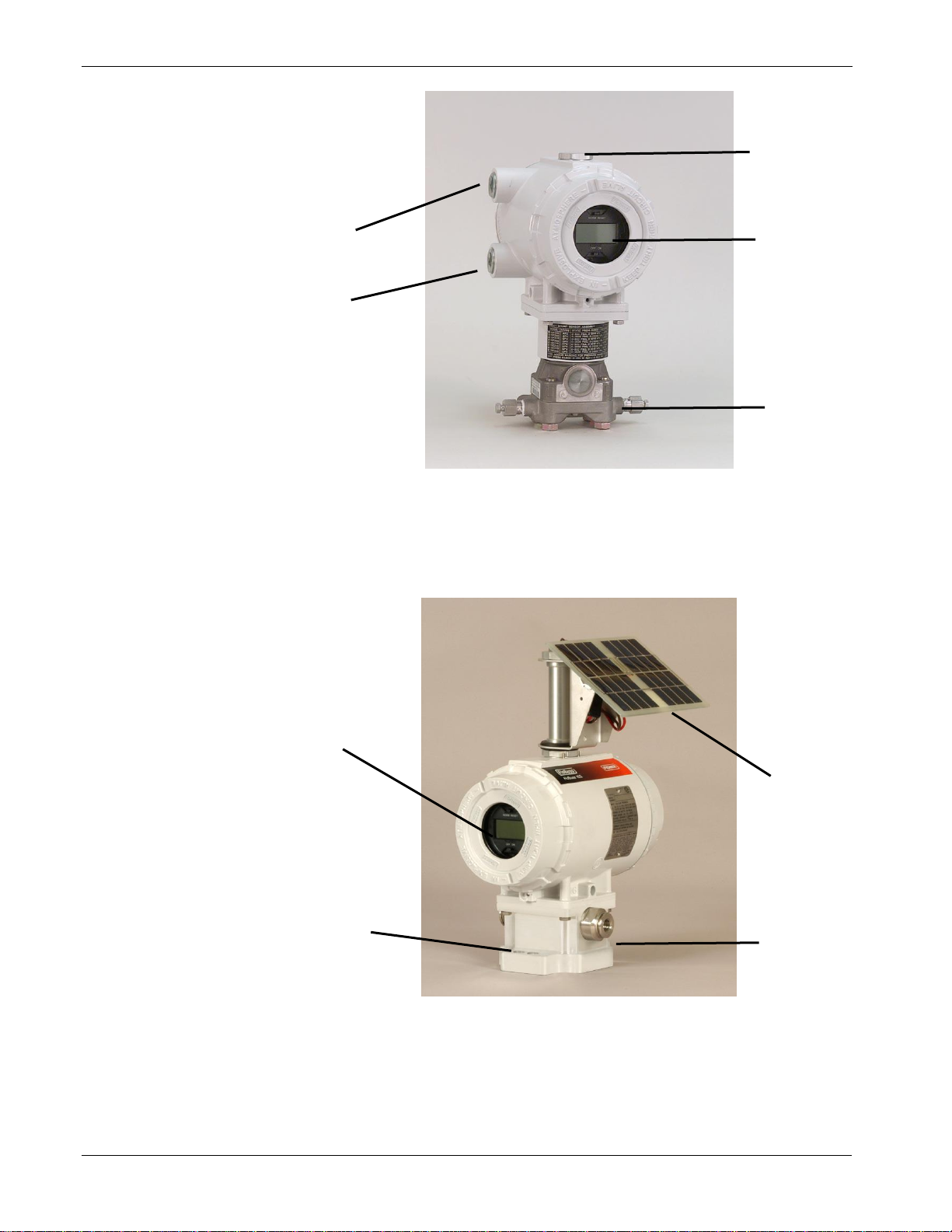
Physical
Configuration
Physically, the FB100 consists of a termination module with optional
I/O points, RAM battery backup board, optional Comm 2
communications module, processor module, battery charger module,
backplane, and optional display housed in a compact, weather-tight
case. The FB100 is packaged in a NEMA 4 windowed enclosure that
mounts on a pipestand, to an orifice plate via a 3- or 5-valve manifold,
to a turbine meter, or to a rotary meter. The aluminum alloy enclosure
protects the electronics from physical damage and harsh environments.
Refer to Figures 1-1 and 1-2.
Page 10
FloBoss 103/104 Instruction Manual
1-4 General Information Revised August-2017
A
Field conduit entry
B
Optional solar panel mounts here
C
Liquid crystal display (LCD)
D
Dual variable sensor (DVS)
Figure 1-1. FloBoss 103 Flow Manager with LCD
A
Liquid crystal display (LCD)
B
Pulse interface module
C
Optional solar panel
D
Pressure transducer
Figure 1-2. FloBoss 104 Flow Manager with Solar Panel
D
B C A
A
A
B
D
C
Page 11
FloBoss 103/104 Instruction Manual
Revised August-2017 General Information 1-5
The enclosure is fabricated from die-cast aluminum alloy with iridite
plating and paint. The NEMA 4 enclosure protects the electronics from
physical damage and harsh environments. The caps at either end of the
enclosure unscrew to allow field maintenance. Two ¾-14 pipe-threaded
holes permit field conduit wiring and communications.
The DVS flange (available on the FB103) has bracket holes that allow
the enclosure and DVS to be mounted on a pipestand or mounting
bracket. The Pulse Interface module (available on the FloBoss 104) has
a universal mounting plate that also has bracket holes that allow you to
mount the enclosure and Interface on a meter.
1.2.2 Hardware
This section discusses the hardware components of the FB100.
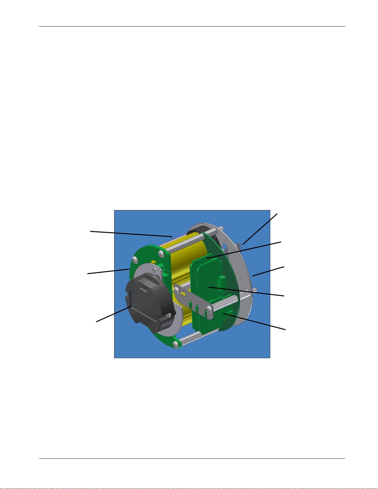
Backplane
The backplane printed circuit board regulates power and routes signals
to the termination module, the processor module, the backup battery
board, the optional communications module, the Dual-Variable Sensor
(DVS, available on the FB103), the Pulse Interface module (available
on the FB104), and the battery charger module. Refer to Figure 1-3.
A
Battery pack (if ordered)
B
Battery Charger module
C
Optional liquid crystal display (LCD)
D
Termination board connectors
E
Processor module
F
Backplane
G
Optional communications module
H
RAM backup
Figure 1-3. Inside the FB100-Series Enclosure
H
D
C
B
A
G
E
F
Page 12

FloBoss 103/104 Instruction Manual
1-6 General Information Revised August-2017
Termination
Module
Located in the terminal side of the explosion-proof housing, the
termination module provides connections to the field wiring. Refer to
Figure 1-4.
A
Local operator interface (LOI)
B
COM2
C
Power supply
D
I/O field wiring
E
LOI (COM1)
F
RTD
Figure 1-4. Wiring Terminals
Connections include the power supply, Local Operator Interface (LOI)
communications, Comm 1 (for EIA-485 [RS-485] communications),
optional Comm 2 (for EIA-232 [RS-232], wireless spread-spectrum
radio, or dial-up modem communications), RTD wiring, and the I/O
field wiring.
The termination board provides surge and static discharge protection for
the field wiring. Electronics include the RTD circuits and the final I/O
drivers/receivers. The termination board also serves as an interface to
the backplane board in the electronics portion of the enclosure.
Processor Module
The 32-bit processor module (see Figure 1-3) contains the processor,
memory (static RAM, Flash EEPROM, and boot ROM), Local Operator
Interface (LOI) EIA-232 (RS-232) communications driver, Comm 1
EIA-485 (RS-485) communications driver, the reset controller, and the
real-time clock.
The processor module (also called the central processor unit or CPU)
provides the Serial Peripheral Interface (SPI) bus; the Liquid Crystal
C
A
E B F
D
Page 13

FloBoss 103/104 Instruction Manual
Revised August-2017 General Information 1-7
Display (LCD) drivers; and controls for the Dual-Variable Sensor
(DVS), the Pulse Interface module, and the optional I/O termination
points.
The microprocessor has low-power operating modes, including
inactivity and low battery condition. The FB100 comes standard with
512 KB of built-in, static random access memory (SRAM) for storing
data and history. The FB100 also has 2 MB of programmable read-only
memory (flash ROM) for storing operating system firmware,
applications firmware, and configuration parameters.
Battery Charger
Module
The battery charger module controls charging of the internal batteries, if
installed. The batteries are three D-size lead-acid batteries providing 2.5
Amp-hours of current at 6.2 volts nominal. The battery charger board
also serves as the interface to the optional LCD assembly, as well as
supporting the On/Off and Norm/Reset jumpers.
A backup battery provides backup power for the static RAM and the
real-time clock. This battery is field replaceable and under normal
conditions has a functional life in excess of five years.
Dual-Variable
Sensor (DVS)
The Dual-Variable Sensor (DVS, available on the FB103) measures
static pressure and differential pressure for orifice flow calculation by
converting the applied pressure to electrical signals and making the
readings available to the processor board.
The DVS housing fastens to a flanged adapter, which, in turn, mounts
with four bolts to the bottom of the enclosure (see Figure 1-1). The
DVS cable connects into the backplane board. Refer to Chapter 6, Dual-
Variable Sensor.
Pulse Interface
Module
The Pulse Interface module (available on the FB104) measures the flow
of natural gas using turbine metering or rotary metering by converting
the applied pressure to electrical signals and counting the number of
pulses (from rotary meter) and making the readings available to the
processor board.
The module housing fastens to a flanged adapter, which, in turn, mounts
with four bolts to the bottom of the enclosure (see Figure 1-2). A cable
connects the module into the backplane board. Refer to Chapter 7, Pulse
Interface Module.
Resistance Temperature
Detector (RTD)
An RTD temperature probe typically mounts in a thermowell on the
meter run. The RTD measures the flowing temperature. Protect RTD
wires either by a metal sheath or by conduit connected to a liquid-tight
conduit fitting on the enclosure.
The RTD wires connect directly to the RTD connector on the
termination board inside the enclosure (see Figure 1-4). Refer to
Chapter 4, Input/Output.
The built-in inputs and outputs (I/O) on the FB100-Series (see Figure
1-4) consist of a 2- or 3-wire 100-ohm Resistance Temperature Detector
(RTD) input interface and a port for either a Dual-Variable Sensor
Page 14

FloBoss 103/104 Instruction Manual
1-8 General Information Revised August-2017
(DVS) or a Pulse Interface module. Three diagnostic analog inputs (AI)
monitor the battery voltage, logical voltage, and enclosure/battery
temperature. Refer to Chapter 4, Input/Output.
Communications
The Local Operator Interface (LOI) port provides a direct, local link
between the FB100-Series and a PC through a Local Operator Interface
cable using EIA-232 (RS-232) communications.
The Comm 1 allows EIA-485 (RS-485) serial communication protocols.
The optional communications card for EIA-232 (RS-232), EIA-485
(RS-485), or dial-up modem activate Comm 2. Refer to Chapter 5,
Communications.
ROCLINK 800
Configuration
Software
The PC-based ROCLINK 800 configuration software enables you to
configure and access the I/O parameters, DVS inputs, flow calculations,
power control, security, and FST programs. Refer to the ROCLINK 800
Configuration Software User Manual (Part D301159X012) for details
concerning software capabilities.
The PC communicates with the FB100-Series through an LOI cable
using EIA-232 (RS-232) communications.
1.2.3 Firmware
The firmware contained in flash ROM on the processor module
determines the functionality of the FB100 and includes:
▪ 1992 AGA-3 flow calculations (with user-selectable AGA8
compressibility Detail, Gross I, or Gross II) for a single meter run
▪ 1996 AGA-7 flow calculations (with user-selectable AGA8
compressibility) for a single meter run.
▪ Memory logging of 240 alarms and 240 events
▪ Archival of minute data from the last 60 minutes for up to 35 points
(Standard History)
▪ Archival of 35 days of hourly data for up to 35 points (Standard
History)
▪ Archival of 35 days of daily data for up to 35 points (Standard
History).
▪ Archival of Min / Max historical data for today and yesterday
(Standard History)
▪ Archival of 5040 entries for up to 15 points at user-specified interval
(Extended History)
▪ Power control (wake up on ring) on optional internal modem
▪ Logic and sequencing control using a user-defined Function
Sequence Table (FST)
▪ Closed-loop (PID) control capabilities (requires optional I/O
termination points)
▪ Communications based on the ROC protocol or Modbus slave, or
optional host, (ASCII or RTU) protocol for use with EFM
applications
Page 15

FloBoss 103/104 Instruction Manual
Revised August-2017 General Information 1-9
▪ Alarm call-in to host for Spontaneous-Report-By-Exception (SRBX)
▪ User-level security.
1.2.4 Options and Accessories
The FB100 supports the following options and accessories:
▪ Communication modules for either EIA-232 (RS-232), EIA-485
(RS-485), dial-up modem
▪ 6 Input/Output (I/O) termination points
▪ Local Operator Interface (LOI) cable
▪ Liquid Crystal Display (LCD) with two-line alpha-numeric viewing
▪ Solar panel mast assembly
▪ Blank plate for the FB103 for use when no DVS is required
Plug-in communication modules allow you to customize the FB100
installation for most communication requirements. Optional
communication cards provide the ability to send and receive data.
The housing accommodates one of the following modules:
▪ EIA-232 (RS-232) or EIA-485 (RS-485) for asynchronous serial
communications
▪ Dial-up modem for communications over a telephone network
Liquid Crystal
Display (LCD)
The optional Liquid Crystal Display (LCD) enables you to view data
and configuration parameters while on site without using the local
operator interface (LOI) and a PC. The LCD display plugs into the
battery charger board and is visible through the window on the front of
the FB100-Series. The LCD can be rotated 90° in either direction.
The LCD’s 2-line display shows one line for a value and the other line
for a 5-character alphanumeric description of the value. The display
operates from the internal 3.3 Volt supply. Through this display, you
can view predetermined information stored in the FB100. You can
define up to 16 items for display. Every three seconds the display
automatically cycles through the configured list of items.
Solar Panel
You can install an external solar panel to recharge the backup batteries.
The panel connects to the CHG+ / CHG- inputs on the termination
board. An integral solar panel (2 W or 5 W, available from Remote
Automation Solutions) connects directly to the battery charger board
assembly. Circuitry on the battery charger board monitors and regulates
the charge based on battery voltage, charging voltage, and temperature.
The FB100-Series requires a minimum 8-volt 200 mA solar panel.
The optional input/output (I/O) termination points provide additional
inputs and outputs for expanded monitoring and control applications.
I/O includes analog input (AI), analog output (AO), discrete input (DI),
discrete output (DO), and pulse input (PI). The DO circuitry is optically
coupled to help isolate the processor board from the output device. I/O
can be used to drive a sampler or odorizer, open a valve, or monitor an
additional analog input.
Page 16

FloBoss 103/104 Instruction Manual
1-10 General Information Revised August-2017
1.2.5 FCC Information
This equipment complies with Part 68 of the FCC rules. Etched on the
modem assembly is, among other information, the FCC certification
number and Ringer Equivalence Number (REN) for this equipment. If
requested, this information must be provided to the telephone company.
This module has an FCC-compliant telephone modular plug. The
module is designed to be connected to the telephone network or
premises’ wiring using a compatible modular jack that is Part 68compliant.
The REN is used to determine the quantity of devices that may be
connected to the telephone line. Excessive RENs on the telephone line
may result in the devices not ringing in response to an incoming call.
Typically, the sum of the RENs should not exceed five (5.0). Contact
the local telephone company to determine the total number of devices
that may be connected to a line (as determined by the total RENs).
If this equipment and its dial-up modem causes harm to the telephone
network, the telephone company will notify you in advance that
temporary discontinuance of service may be required. However, if
advance notice is not practical, the telephone company will notify the
customer as soon as possible. In addition, you will be advised of your
right to file a complaint with the FCC if you believe it necessary.
The telephone company may make changes to its facilities, equipment,
operations, or procedures that could affect the operation of the
equipment. If this happens, the telephone company will provide advance
notice so you can make the necessary modifications to maintain
uninterrupted service.
If you experience trouble with this equipment or the dial-up modem,
contact Remote Automation Solutions TechSupport (at 641-754-3923)
for repair or warranty information. If the equipment harms the telephone
network, the telephone company may request that you disconnect the
equipment until the problem is resolved.
1.3 Product Functions
This section describes the functions of the FB100-Series, most of which
are determined by firmware and are configurable using ROCLINK 800.
The features and applications include:
▪ Flow calculations for an orifice meter (AGA3) or rotary or turbine
meter (AGA7)
▪ Extensive historical data archival
▪ Memory logging of 240 alarms and 240 events
▪ Security with local and remote password protection
▪ Logic and sequencing control using a user-defined FST program
▪ Spontaneous-Report-by-Exception (SRBX) capability
Page 17

FloBoss 103/104 Instruction Manual
Revised August-2017 General Information 1-11
1.3.1 Flow Measurement
The primary function of the FB100-Series is to measure the flow of
natural gas through an orifice or turbine or rotary meter in accordance
with the 1992 American Petroleum Institute (API) and American Gas
Association (AGA) standards.
The primary inputs used for AGA3 flow measurement function are
differential pressure, static pressure, and temperature. The differential
and static pressure inputs, which are sampled once per second, come
from the Dual-Variable Sensor. The temperature input, which is
sampled and linearized once per second, comes from an RTD probe.
The primary inputs used for AGA7 flow measurement are Pulse Input
(PI) counts, static pressure, and temperature. The Pulse Input counts are
acquired from a rotary meter (pulse interface module) or turbine meter
(PI on termination board), the static pressure (including auxiliary
pressure) inputs come from the pressure transducers, and the
temperature input is read from an RTD probe.
Flow Calculations for
Orifice Metering
The flow calculation is in accordance with ANSI/API 2530-92 (AGA
Report No. 3 1992), API Chapter 14.2 (AGA Report No. 8 1992 2nd
printing 1994), and API Chapter 21.1. The flow calculation may be
configured for either metric or English units.
Flow Timer
The differential pressure stored for each second is compared to the
configured low flow cutoff. If the differential pressure is less than or
equal to the low flow cutoff or the converted static pressure is less than
or equal to zero, flow is considered to be zero for that second.
Flow time for a recalculation period is defined to be the number of
seconds for which the differential pressure exceeded the low flow
cutoff.
Input and Extension
Calculation
Each second the FB100-Series stores the measured input for differential
pressure, static pressure, and temperature and calculates the Integral
Value (IV). IV is the square root of the absolute upstream static pressure
multiplied by the differential pressure.
The FB100-Series calculates flow time averages of the inputs and the IV
over the configured calculation period, unless there is no flow for an
entire calculation period. Linear averages of the inputs are recorded to
allow monitoring during no flow periods.
Instantaneous Rate
Calculations
The instantaneous value of the Integral Value (IV) is used with the
previous calculation period’s Integral Multiplier Value (IMV) to
compute the instantaneous flow rate.
The IMV is defined as the value resulting from the calculation of all
other factors of the flow rate equation not included in the IV. The
instantaneous flow rate is used with the volumetric heating value to
compute the instantaneous energy rate.
Flow and Energy
The averages of the differential and static pressure, temperature, and
sum of the IV are used with the flow time to compute the flow and
Page 18

FloBoss 103/104 Instruction Manual
1-12 General Information Revised August-2017
Accumulation
energy over the calculation period. The flow and energy are then
accumulated and stored at the top of every hour. At the configured
contract hour, the flow and energy are then stored to the Daily Historical
Log and zeroed for the start of a new day (contract hour).
Flow Calculations for
Turbine Metering
The turbine flow calculation is in accordance with 1996 AGA Report
No. 7 (1993 API Chapter 21.1). The FloBoss performs 1992 AGA8
compressibility calculations in accordance with AGA Report No. 8
1992 (API Chapter 14.2).
Once every scan period, the FB100 processes the pulse counts,
determines the number of pulse counts since the last reading, and
calculates a rate. Next, the static pressure and auxiliary pressure values
are read. Then the temperature is read and linearizing compensation is
applied to the pressure readings if necessary.
All resultant values are stored in the current value database. The values
are taken from the current value database and used to calculate the
Minute, Hour, and Daily historical values.
Once a minute and once an hour, the values are logged along with other
configured values to the Historical Database. At the configured Contract
Hour, the values are stored to the Daily Historical Log and zeroed for
the start of a new day.
1.3.2 History Points
History is saved to 2 databases: Standard and Extended History. The
number of entries/logs available to Standard and Extended History is
configurable.
The Standard history archives up to 35 points (8 are pre-configured) of
min/max, minute, hourly and daily values. The min/max values are from
today and yesterday; the minute values are from the last 60 minutes; the
hourly values are from the last 35 days; and the daily values are from
the last 35 days.
The Extended History database creates one entry for up to 15 points at a
user-specified interval (see Specifications table). All the points in the
Extended History will be logged at the same interval.
The default setting for Extended history archives 4 points of 10-minute
values (from the last 35 days). 10-minute archiving provides a
monitoring resolution similar to a chart recorder.
The first eight history points are pre-configured for flow metering
history and cannot be changed:
1. Flowing Minutes Today (Accumulate archive type).
2. Differential Pressure for AGA3 (Average) or Accumulated Raw
Pulses for AGA7 (Totalize).
3. Static or Line Pressure (Average).
4. Flowing Temperature (Average).
Page 19

FloBoss 103/104 Instruction Manual
Revised August-2017 General Information 1-13
5. IMV (Integral Multiplier Value) for AGA3 (Average) or BMV
(Base Multiplier Value) for AGA7 (Average).
6. Pressure Extension for AGA3 (Average) or Today’s Total for AGA7
(Totalize).
7. Instantaneous Flow (Accumulate).
8. Instantaneous Energy (Accumulate).
History Point 2 (AGA3), History Point 3, History Point 4, and History
Point 6 (AGA3) are all pre-defined as an Average Archive Type that
employs one of the following techniques:
▪ Flow dependent time-weighted linear averaging (default)
▪ Flow dependent time-weighted formulaic averaging
▪ Flow-weighted linear averaging
▪ Flow-weighted formulaic averaging
The Averaging Technique is selected by using ROCLINK 800 software.
The selected Averaging Technique is applied to the meter inputs. Refer
to the ROCLINK 800 Configuration Software User Manual (Part
D301159X012).
Minute Historical
Log
The FB100 has a 60-minute historical log for every history point. The
Minute Historical Log stores the last 60 minutes of data from the current
minute. Each history point has Minute Historical Log entries, unless the
history point is configured for FST-controlled logging.
Hourly Historical
Log
The FB100 has a total of 35 days of hourly historical logs available for
every history point. The Hourly Historical Log is also called the
periodic database. With two exceptions (FST Minute and FST Second
logging), the system records the Hourly Log at the beginning of every
hour.
The time stamp for periodic logging consists of the month, day, hour,
and minute. The exception is for FST Second logging, in which the time
stamp consists of the day, hour, minute, and second.
Daily Historical
Log
The FB100 has a total of 35 daily historical logs for every history point.
The Daily Log is recorded at the configured contract hour every day
with a time stamp that is the same as the Hourly Log. Each history point
has daily historical log entries, unless the history point is configured for
FST-controlled logging.
Mix/Max Historical
Log
The Min / Max database displays the minimum and the maximum
values for the database points over a 24-hour period for today and
yesterday. You can view the Min / Max historical log but not save it to
disk.
Mix/Max Historical
Log
The Min / Max database displays the minimum and the maximum
values for the database points over a 24-hour period for today and
yesterday. You can view the Min / Max historical log but not save it to
disk.
Page 20

FloBoss 103/104 Instruction Manual
1-14 General Information Revised August-2017
Extended History
Log
The FB100 has configurable archive times (1 minute to 60 minutes)
which, in turn, determine the number of entries.
Alarm Log
The Alarm Log contains the change in the state of any alarm signal that
has been enabled for alarms. The system Alarm Log has the capacity to
maintain and store up to 240 alarms in a “circular” log. The Alarm Log
has information fields that include time and date stamp, alarm clear or
set indicator, and either the Tag name of the point or a 14-byte detail
string in ASCII format.
In addition to providing functionality for appending new alarms to the
log, the Alarm Log allows host packages to request the index of the
most recently logged alarm entry. Alarm logging is available internally
to the system, to external host packages, and to FSTs. Alarm Logs are
not stored to the flash ROM during the Save Configuration function in
ROCLINK 800 software.
The Alarm Log operates in a circular fashion with new entries
overwriting the oldest entry when the buffer is full. The Alarm Log
provides an audit history trail of past alarms. The Alarm Log and the
Event Log are stored separately to prevent recurring alarms from
overwriting configuration audit data.
Event Log
The Event Log contains changes to any parameter within the FB100
made through the protocol. This Event Log also contains other FloBoss
events, such as power cycles, cold starts, and disk configuration
downloads. The Event Log provides an audit history trail of past
operation and changes.
The system Event Log has the capacity to maintain and store up to 240
events in a circular log. The Event Log has information fields that
includes point type, parameter number, time and date stamp, point
number if applicable, the operator identification, and either the previous,
current parameter values, and either the Tag name of the point or a 14byte detail string in ASCII format.
In addition to providing functionality for appending new events to the
log, the Event Log allows host packages to request the index of the most
recently logged event entry. Event logging is available internally to the
system, to external host packages, and to the FST.
Event logs are not stored to flash ROM when you perform a Save
Configuration using ROCLINK 800 software. The Event Log operates
in a circular fashion with new entries overwriting the oldest entry when
the buffer is full. The Event Log provides an audit trail history of past
operation and changes. The Event Log and Alarm Log are stored
separately to prevent recurring alarms from overwriting configuration
audit data.
The FB100 has the ability to limit the AGA calculation-related events to
only critical events. This can keep unnecessary events from being
logged and filling the event log. The events which will not be logged are
Page 21

FloBoss 103/104 Instruction Manual
Revised August-2017 General Information 1-15
temperature, pressure, Reynolds number, and warnings for orifice
diameter, pipe diameter, and beta ratio.
1.3.3 Security
The FB100 provides for security within the unit. A maximum of 16 logon identifiers (IDs) may be stored. In order for the unit to communicate,
the log-on ID supplied to ROCLINK 800 software must match one of
the IDs stored in the FB100. The Local Operator Interface port (Security
on LOI) has security Enabled by default. The Comm 1 and Comm 2 can
likewise be configured to have security protection, but is disabled by
default.
1.3.4 Function Sequence Tables (FST)
The FB100 supports FST user programmability. Two FST programs
can be developed with a maximum length of 3000 bytes each (typically
300 lines of code). The number of FST lines per execution cycle can be
configured in ROCLINK 800 software. The number set on the ROC >
Information screen determines both FST programs.
The FST code resides in static RAM and is backed up to flash memory
when the Save Configuration function is issued through ROCLINK 800
software.
Note: For further information on FSTs, refer to the Function Sequence
Table (FST) User Manual (D301058X012).
1.3.5 PID Control
PID Control is available when the optional I/O termination points are
installed. PID (Proportional, Integral, and Derivative) functionality
calculates both the Primary Control and Override Control change in
output. PID Control then selects which Control is to be used, based
upon whether the High Override Type Select or Low Override Type
Select is chosen and adjusts the Output control as necessary. The Output
of the PID functions can be implemented through an Analog Output or
the two Discrete Outputs.
1.3.6 Spontaneous-Report-By-Exception (SRBX) Alarming
The SRBX functionality allows a communications port to be set up to
enable the FloBoss to contact the host computer when specified alarm
conditions exist. To configure SRBX alarming, each comm port must
have the SRBX parameter enabled, each point must have the alarming
parameter enabled, and points must have the SRBX Set on Clear
parameter set.
Page 22

FloBoss 103/104 Instruction Manual
1-16 General Information Revised August-2017
1.3.7 Pass Through Communications
Pass Through Communications allow you to configure an FB100 unit to
send Pass Through messages, when using a FB100. By using any of the
FB100 communications ports, Pass Through Mode allows data to be
received by one unit and then passed through to other devices connected
on any other communications port. For example, the host communicates
via a radio (when an external radio is used with the EIA-232 module) on
the FB100’s Comm 2 port. You can then connect other FB100s via EIA485 (RS-485) on the Comm 1 port of the first FB100, and then all the
FB100s can use the one radio to communicate to the host.
Notes:
▪ If you configure Comm 2 as a dial-up modem, you must configure it
as a receiving port. If you configure Comm 2 as an RS-232 port, it
has no such restrictions.
▪ The Device Group (located on the General tab of the ROC >
Information screen) of the FB100 receiving the data must match the
Device Group of the FB100(s) to which the data is passed. If the
Device Group does not match, the data is not forwarded.
1.3.8 Protocol Automatic Switching
The FB100 has the capability to communicate with ROC or Modbus
protocol. With the standard version of FloBoss firmware, Modbus Slave
is standard. If you require Modbus Host functionality, contact your local
sales representative.
1.3.9 User C Capability
The FB100 supports programs written in User C. This capability allows
you to write and subsequently load special features into the FB100 to
enhance the functionality. User C programs typically provide the ability
to interface with alternate metering equipment, perform alternate
calculation methods, or communicate with alternate protocols. Consult
your local sales representative for User C applications.
1.4 Product Electronics
This section describes the FB100 electronics. For communication
modules, refer to Chapter 4. Refer to Chapter 5 for information on the
I/O termination points, Chapter 6 for the Dual-Variable Sensor (DVS),
or Chapter 7 for the Pulse Interface module.
1.4.1 Termination Board Overview
Components of the termination board (see Figure 1-4) support the
functionality of the FloBoss 100-Series and include:
▪ Local operator interface (LOI) EIA-232 (RS-232) terminations
Page 23

FloBoss 103/104 Instruction Manual
Revised August-2017 General Information 1-17
▪ EIA-485 (RS-485) communications (Comm 1) terminations
▪ RTD input terminations
▪ Optional I/O and terminations
▪ Remote charge terminations
▪ Optional Comm 2 terminations
1.4.2 Processor and Memory
The FB100-Series derives processing power from a 32-bit
microprocessor. The 32-bit CMOS microprocessor features dual 32-bit
internal data buses and a single 8-bit external data bus. The unit can
address up to 4 MB of memory, including high-speed direct memory
access.
The FB100 has 512 KB of static random access memory (SRAM) for
storing interrupt vectors, Proportional, Integral, and Derivative alarms,
events, and history data.
The FB100 also has a 2 MB flash memory chip for storing the operating
system factory code, configuration parameters, and User C programs.
1.4.3 Liquid Crystal Display
An optional two-line Liquid Crystal Display (LCD) panel mounts on the
Battery Charger module.
The LCD allows you to view the current and past gas volumes on site
without requiring a PC. The LCD provides you a visual indication of the
status of the meter run by displaying the historical performance data to
help ensure the health and integrity of your installation.
The LCD panel remains on at all times when the power is applied in the
valid operating range. The panel cycles its display through a configured
list of up to 16 parameter values, with the first seven being preconfigured. The first three displays show values for time, date, and
battery condition and cannot be configured. The next five displays show
certain flow parameters and are factory configured, but you may change
their configuration.
To configure the list of values for the LCD panel, refer to the LCD User
List Setup procedure in the ROCLINK 800 Configuration Software User
Manual (Part D301159X012).
1.4.4 Communications Ports
The FB100 provides two standard and one optional communication
ports:
▪ Standard Operator interface port EIA-232 (RS-232) – LOI.
▪ Standard EIA-485 (RS-485) Communications – Comm 1.
▪ Optional EIA-232 (RS-232), or Dial-up Modem Communications –
Comm 2.
Page 24

FloBoss 103/104 Instruction Manual
1-18 General Information Revised August-2017
Local Operator Interface
(LOI) Port
The Local Operator Interface (LOI) port provides direct
communications between the FB100 and the serial port of an operator
interface device, such as personal computer using an EIA-232 (RS-232)
link.
The interface allows you to access the FB100 (using ROCLINK 800
software) for configuration and transfer of stored data. The LOI port is
capable of initiating a message in support of Spontaneous-Report-byException (SRBX) alarming.
The LOI terminal on the Termination module provides wiring access to
a built-in EIA-232 (RS-232) serial interface, which is capable of up to
19.2K bps operation. The operator interface port supports ROC or
Modbus protocol communications. The LOI also supports the log-on
security feature of the FB100, if you enable the Security on LOI through
the ROCLINK 800 software.
EIA-485 (RS-485) Serial
Communications on
COMM1
Use Comm 1 to monitor or alter the FB100-Series from a remote site,
using a host or ROCLINK 800 software. Comm 1 supports baud rates
up to 19,200 bps. Comm 1 also supports the log-on security feature of
the FloBoss unit if you have enabled the security on Comm 1 in
ROCLINK 800 software.
Comm 1 sends and receives messages using the ROC or Modbus
protocol. Comm 1 is capable of initiating a message in support of
Spontaneous-Report-by-Exception (SRBX) alarming. Comm 1 permits
EIA-485 (RS-485) serial communication protocols that meet EIA-485
(RS-485) specifications for differential, asynchronous transmission of
data over distances of up to 1220 m (4000 ft). The EIA-485 (RS-485)
drivers are designed for true multi-point applications with multiple
devices on a single bus.
The default values for the EIA-485 (RS-485) communications are:
▪ 9600 Baud
▪ 8 Data Bits
▪ 1 Stop Bit
▪ No Parity
▪ 10 millisecond Key On Delay and
▪ 10 millisecond Key Off Delay
The maximum baud rate is 19,200 bps. You can disable the Comm 1
port (the default state is enabled) using the ROCLINK 800 Radio Power
Control screen (select Configure > Control> Radio Power Control
from the ROCLINK 800 software’s menu).
Optional
Communications
Module (COMM2)
Two plug-in communication printed circuit boards and one
communication module allow you to customize the FB100 installation
for most communication requirements. The communication PCBs and
module provide an interface for the host communications Comm 2 port.
These cards permit serial communication protocols and dial-up modem
communications.
Page 25

FloBoss 103/104 Instruction Manual
Revised August-2017 General Information 1-19
The Comm 2 port is capable of initiating a message in support of
Spontaneous-Report-by-Exception (SRBX) alarming. Refer to Chapter
3 for additional information. One of the following card types can be
accommodated:
▪ EIA-232 (RS-232) for asynchronous serial communications (baud
rate up to 19,200).
▪ Dial-up modem for communications over a telephone network
(default at 2400 baud).
1.4.5 RTD Input
The FB100 supports a direct input from a Resistance Temperature
Detector (RTD) sensor to measure flowing temperature. The RTD has a
measurement range of -40 to 240°C (-40 to 464°F). The terminals for
the RTD wires are labeled “RTD” (see Figure 1-4).
During operation, the RTD is read once per second. The value from the
RTD is linearized, and then it is sent to processing as Analog Input (AI)
Point Number A3. The AI routine converts this value to engineering
units, and checks alarming. To conserve power, the RTD power is
switched on and off. During calibration, the RTD power is on
constantly. When calibration completes, the RTD cycles power again.
1.4.6 Real-Time Clock
The real-time clock provides the FB100 with the time of day, month,
year, and day of the week. The real-time clock automatically switches to
backup power when the FB100 loses primary input power. Backup
power for the real-time clock is adequate for a period in excess of five
years with no power applied to the FB100.
1.4.7 Diagnostic Monitoring
The electronics board has three diagnostic inputs incorporated into the
circuitry for monitoring battery voltage, logical voltage, and board
temperature. Access these analog inputs using the I/O function of
ROCLINK 800 software. The three values are available as the following
Analog Input (AI) points:
▪ E1 – logical voltage
▪ E2 – battery voltage
▪ E5 – board (battery) temperature
1.4.8 Automatic Self Tests
The FB100 performs the following self-tests on a periodic basis:
▪ Software and hardware watchdog
▪ Sensor operation
▪ Memory validity
Page 26

FloBoss 103/104 Instruction Manual
1-20 General Information Revised August-2017
The FB100 operates with its internal batteries down to 5.4 volts dc. The
LCD becomes active when you apply input power with the proper
polarity and startup voltage (typically set greater than 8.0 volts) to the
CHG+ / CHG- connector (provided the power input fusing/protection is
operational). The battery and logical voltage tests ensure that the FB100
operates in the optimum mode.
The CPU controls the software watchdog circuit. The software arms the
watchdog timer every second. If the watchdog timer is not armed for a
period of 9 seconds, then the watchdog timer forces the FB100 to reset.
If necessary, the software automatically resets. The CPU also controls
the hardware watchdog circuit and monitors the power to the hardware.
If the battery voltage drops below 5.4 volts, the FB100 automatically
shuts down.
The FloBoss 103 monitors its orifice-metering Dual-Variable Sensor for
accurate and continuous operation. The FloBoss 104 monitors its Pulse
Interface Module.
1.4.9 Low Power Mode
Sleep mode places the CPU in a low power mode. Low voltage
detection circuitry (preset at a low voltage limit of 5.4 V) monitors the
battery voltage. During Sleep mode, sub-modules power down. The
FB100 enters sleep mode after one minute of inactivity on the
communication ports. Optionally, you can turn off sleep mode, which
enables your FB100 to stay active all the time.
Wake-up from sleep mode occurs when the FB100 receives either a
timed interrupt from the real-time clock or a signal from one of the
communication ports.
Page 27

FloBoss 103/104 Instruction Manual
Revised August-2017 General Information 1-21
1.5 Additional Technical Information
Refer to Table 1-1 for additional and most-current technical documents
(available at www.EmersonProcess.com/Remote).
Table 1-1. Additional Technical Information
Name
Form Number
Part Number
FloBoss™ 103 Flow Manager
FB103
D301152X012
FloBoss™ 104 Flow Manager
FB104
D301200X012
FloBoss™ 103 and 104 Firmware
FB100:FW1
D301157X012
DVS205 Dual-Variable Sensor
DVS205
D301569X012
Page 28

FloBoss 103/104 Instruction Manual
1-22 General Information Revised August-2017
[This page is intentionally left blank.]
Page 29

FloBoss 103/104 Instruction Manual
Revised August-2017 Installation and Use 2-1
Chapter 2 – Installation and Use
In This Chapter
2.1 Installation Overview ........................................................................ 2-1
2.2 Installation Requirements ................................................................ 2-2
2.2.1 Environmental Requirements ............................................... 2-2
2.2.2 Site Requirements ................................................................ 2-3
2.2.3 Compliance with Hazardous Area Standards ...................... 2-3
2.3 Mounting .......................................................................................... 2-4
2.3.1 General Guidelines ............................................................... 2-4
2.3.2 Pipe Stand Mounting (FloBoss 103) .................................... 2-7
2.3.3 Orifice Plate Mounting (FloBoss 103) .................................. 2-7
2.3.4 Meter Mounting (FloBoss 104) ............................................. 2-8
2.4 Startup and Operation ................................................................... 2-11
2.4.1 Starting the FB100 ............................................................. 2-11
2.4.2 Operation ............................................................................ 2-12
2.5 Configuration.................................................................................. 2-13
This chapter focuses on the installation, mounting, and startup of the
FB100.
2.1 Installation Overview
The following steps detail the general process for installing a FloBoss
103 to a pipe stand or orifice plate or for installing a FloBoss 104 to a
turbine or rotary meter. Review each section in this chapter for specific
instructions.
1. Install the pipe stand (if pipe stand mounting) according to the
directions included with the pipe stand.
2. Remove the orifice/meter run from service.
3. Mount the FB100 assembly according to the procedures in Section
2.3.
4. Install the RTD and connect it to the termination board.
5. Connect the FB100 to the operator interface (ROCLINK 800
software).
6. Power the FB100. If powered externally, wire the unit to the
external power source.
7. Calibrate the input(s) from the Dual-Variable Sensor or Pulse
Interface module.
8. Calibrate the RTD input.
9. Connect the FB100 to any other external communication devices or
networks.
Page 30

FloBoss 103/104 Instruction Manual
2-2 Installation and Use Revised August-2017
Place the meter run in service and monitor with ROCLINK 800
software for proper operation.
2.2 Installation Requirements
Careful planning helps to ensure a smooth installation. Be sure to
consider location, ground conditions, climate, and site accessibility, as
well as the suitability of the FB100-Series application while planning an
installation.
The versatility of the FB100 enables you to use it in many types of
installations. For additional information concerning a specific
installation, contact your local sales representative.
Note: The FB100 has been tested and been found to comply with the
limits for a Class A digital device, pursuant to part 15 of the
FCC rules. These limits provide reasonable protection against
harmful interference when the equipment operates in a
commercial environment. This equipment generates, uses, and
can radiate radio frequency energy. If not installed and used in
accordance with this instruction manual, the FB100 may cause
harmful interference to radio communications. Operation of the
equipment in a residential area is likely to cause harmful
interference, in which case you will be required to correct the
interference at your own expense.
2.2.1 Environmental Requirements
The FB100 enclosure is classified as a NEMA 4 equivalent enclosure.
This provides the level of protection required to keep the units operating
under a variety of weather conditions.
The FB100 is designed to operate over a wide range of temperatures.
However, in extreme climates it may be necessary to moderate the
temperature in which the unit must operate.
The FB100 is designed to operate over a –40°C to +75°C (–40°F to
+167°F) temperature range. The LCD temperature range is –25°C to
+70°C (–13°F to +158°F). When mounting the FB100, be aware of
external devices that could have an effect on the operating temperature.
Operation beyond the recommended temperature range could cause
errors and erratic performance. Prolonged operation under extreme
conditions could also result in failure of the unit.
Check the installation for mechanical vibration. Do not expose the
FB100 to levels of vibration that exceed 2g for 15 to 150 Hz and 1g for
150 to 2000 Hz.
Page 31

FloBoss 103/104 Instruction Manual
Revised August-2017 Installation and Use 2-3
2.2.2 Site Requirements
Careful consideration in locating the FB100 on the site can help prevent
future operational problems. Consider the following when choosing a
location:
▪ Local, state, and federal codes often place restrictions on monitoring
locations and dictate site requirements. Examples of these
restrictions are fall distance from a meter run, distance from pipe
flanges, and hazardous area classifications.
▪ Locate the FB100 to minimize the length of signal and power
wiring.
▪ When using solar-powered FB100s, orient solar panels to face due
(not magnetic) south in the Northern hemisphere and due (not
magnetic) north in the Southern hemisphere. Make sure nothing
blocks the sunlight from 9:00 am to 4:00 pm.
▪ Locate antennas for radio and cellular communications with an
unobstructed signal path. If possible, locate antennas at the highest
point on the site and avoid aiming antennas into storage tanks,
buildings, or other tall structures. Allow sufficient overhead
clearance to raise the antenna.
▪ To minimize interference with radio or cellular communications,
locate the FB100 away from electrical noise sources, such as
engines, large electric motors, and utility line transformers.
▪ Locate the FB100 away from heavy traffic areas to reduce the risk of
being damaged by vehicles. However, provide adequate vehicle
access to aid in monitoring and maintenance.
2.2.3 Compliance with Hazardous Area Standards
The FB100 without optional mast kit has hazardous location approval
for Class I, Division 1, Groups C to D exposures. The FB100 also has a
Class I, Division 2, Groups A, B, C & D approval. The Class, Division,
and Group terms are defined as:
▪ Class defines the general nature of the hazardous material in the
surrounding atmosphere. Class I is for locations where flammable
gases or vapors may be present in the air in quantities sufficient to
produce explosive or ignitable mixtures.
▪ Division defines the probability of hazardous material being present
in an ignitable concentration in the surrounding atmosphere.
Division 1 locations are presumed to be hazardous. Division 2
locations are areas where gas, dust or vapors can exist under
abnormal conditions.
▪ Group defines the hazardous material in the surrounding
atmosphere. Groups A to D are defined as:
o Group A – Atmosphere containing acetylene, gases or vapors of
equivalent hazards.
Page 32

FloBoss 103/104 Instruction Manual
2-4 Installation and Use Revised August-2017
o Group B – Atmosphere containing hydrogen, gases or vapors of
equivalent hazards.
o Group C – Atmosphere containing ethylene, gases, or vapors of
equivalent hazards.
o Group D – Atmosphere containing propane, gases, or vapors of
equivalent hazards.
For the FB100 to be approved for hazardous locations, install it
according to the National Electrical Code (NEC) Article 501, and any
local code requirements, if applicable.
Caution
When installing units in a hazardous area, make sure all installation
components selected are labeled for use in such areas. Installation and
maintenance must be performed only when the area is known to be nonhazardous. Installation in a hazardous area could result in personal
injury or property damage.
2.3 Mounting
When choosing an installation site, be sure to check all clearances.
Provide adequate clearance for wiring and service. The optional LCD
should be visible and accessible for the on-site operator. When using a
solar panel, allow adequate clearance and do not obstruct the view of the
sun. Allow adequate clearance and an obstructed location for antennas
when using cellular phones or radios.
2.3.1 General Guidelines
You can mount the FB103 enclosure assembly directly to an orifice
plate using a 3- or 5-valve manifold or by using the standard Rosemount
2" pipe mounting kit with impulse tubing connecting the FloBoss 103 to
the meter run.
As shown in Figure 2-1, the DVS is factory-mounted directly on a flat
flange to the FB103 enclosure with four bolts. An adapter coupling
provides the mounting interface between the enclosure and the DVS
(see Chapter 4 for additional information).
If you order the FB103 without a DVS, the factory mounts an optional
blank plate to the flange. The blank plate mounts onto a pipe stand,
using the standard Rosemount 2-inch pipe mounting kit and 2 usersupplied bolts (5/16 X 1 3/8) and lock washers.
You can mount the FB103 either of two ways:
▪ On a pipe stand:
The FloBoss 103 can mount to a 2-inch pipe stand. Ensure that the
pipe stand meets all weight requirements and installation conforms
to local building codes.
Page 33

FloBoss 103/104 Instruction Manual
Revised August-2017 Installation and Use 2-5
▪ On an orifice plate:
Directly mount to an orifice plate via a 3- or 5-valve manifold.
With either mounting method, the pressure inputs must be piped to the
process connections on the DVS. For more information on process
connections, refer to Chapter 6.
Refer to Figures 2-1 to 2-3 for dimensions. If you intend to use the
FB100 with a 5 Watt solar panel, the dimensions are 22.86 mm W by
48.01 mm H by 31.12 mm D (9.00 in. W by 18.90 in. H by 12.25 in. D).
Figure 2-1. Dimensions of the FB103 (without Solar Panel)
c
Page 34

FloBoss 103/104 Instruction Manual
2-6 Installation and Use Revised August-2017
Figure 2-2. Dimensions of FB104
Figure 2-3. Dimensions with 2-watt Solar Panel and LCD
c
Page 35

FloBoss 103/104 Instruction Manual
Revised August-2017 Installation and Use 2-7
2.3.2 Pipe Stand Mounting (FloBoss 103/FloBoss 104)
To install the FloBoss 103/ FloBoss 104 on a 2-inch pipe stand:
1. Install the pipe stand per the directions included with the pipe stand.
2. Remove the orifice/meter run from service.
3. Install the FloBoss on the pipe stand using clamps or mounting
brackets. Refer to Figure 2-4 (for FB103) and Figure 2-5 (for
FB104).
2.3.3 Orifice Plate Mounting (FloBoss 103)
To install the FloBoss 103 on an orifice plate:
1. Remove the orifice/meter run from service.
2. Install the FloBoss 103 on the meter run using a manifold and
hardware to secure the FloBoss 103 to the orifice flanges. Refer to
Figure 2-4.
Figure 2-4. FB103 Mounting Options
Page 36

FloBoss 103/104 Instruction Manual
2-8 Installation and Use Revised August-2017
Figure 2-5. FB104 Mounting Option for ATEX unit
2.3.4 Meter Mounting (FloBoss 104)
The factory installs the Pulse Interface module to the base of the FB104.
Do not remove the FB104 from the Pulse Interface module; you may
damage cable connections between the interface and the FB100-Series
backplane.
Caution
Only the factory can install or remove the Pulse Interface module.
Cabling between the module and backplane can be easily damaged. The
module is not a user-serviceable component.
Note: The Pulse Interface module is not equipped to provide a
temperature input to the FB100 for gas compensations in AGA7
calculation. Instead, this input should come directly into the
FB104 from the built-in RTD input on the termination board.
If the FloBoss 104 has an optional LCD, orient the enclosure to ensure
that the display is visible after installation.
To mount the Pulse Interface module to the top of the rotary meter or
turbine meter:
Turbine Meter
To attach the FB104 and Pulse Interface module to a turbine meter,
attach the meter adapter at the base of the Pulse Interface module to
the meter housing with user-supplied 5/16-inch bolts (see Figure 2-6).
Page 37

FloBoss 103/104 Instruction Manual
Revised August-2017 Installation and Use 2-9
A
Pulse Interface Module
B
Meter Adapter
C
Dowel pins extend 1.25 in min.
D
Meter housing
E
User-supplied 5/16-18 cap screws
F
Shaft adapter
G
0.68 – 0.71 in
Figure 2-6. Mounting Pulse Interface Module to Meter Housing on non-ATEX FB104
Rotary Meter
Use the following steps to attach the FB104 and Pulse Interface
module to a rotary meter:
1. Determine which threaded hex shaft adaptor to use.
The short adaptor has a 0.126–0.128 inch inner diameter at one end
and a 0.110–0.112 inch inner diameter at the other end. The short
adaptor requires a rotary meter shaft length of 0.150–0.210 inch.
The long adaptor has a 0.187–0.189 inch inner diameter. The long
adaptor requires rotary meter shaft length of 0.150–0.260 inch.
2. If you use the short shaft adaptor, determine which end of the
adaptor fits tighter to the shaft. The end that fits tighter is the end on
which you install the set-screw.
3. Loosely install the 5-40 set-screw into the appropriate hole on the
shaft adaptor. The kit includes two set-screws: 0.125 inch and 0.188
inch long. The 0.125 inch long set-screw is for the long shaft
adaptor. The 0.188 inch long set-screw is for the short shaft adaptor.
4. Place the adaptor with the set-screw inserted over the rotary meter
shaft, and tighten the set-screw to lock the adaptor in place.
C
G
D
B
E
A
F
Page 38

FloBoss 103/104 Instruction Manual
2-10 Installation and Use Revised August-2017
5. Thread the magnet assembly on to the shaft adaptor until the top of
the magnet is between 0.68–0.71 inches above the meter housing
(refer to Figure 2-6). The magnet set-screw should be positioned
over a flat in the hex shaft adaptor. Tighten the set-screw to lock the
magnet assembly in place. Refer to Figure 2-7 and Figure 2-8.
Note: Align the magnet assembly so that the magnet set-screw
contacts one of the shaft adaptor flats and not the shaft
adaptor set-screw or any threaded areas.
A
Magnet
B
Magnet Set-screw
C
Shaft Adaptor
D
Shaft Adaptor Set-screw
E
1.90 in. Max – 1.70 in. Min
Figure 2-7. Magnet Installed on Long Shaft Adaptor
A
0.66 in. Max – 0.46 in. Min
Figure 2-8. Magnet Installed on Short Shaft Adaptor
6. Insert 0.25 inch diameter dowel pins (user-supplied) in two of the
5/16-18 UNC threaded holes on the top of the rotary meter. These
pins should extend at least 1.25 inches above the meter housing so
that they can be easily removed later.
7. Place the gasket provided over the dowel pins and rest it flatly on
the meter housing.
8. Position the FB104 over the meter housing and carefully lower it
into place using the dowel pins to guide alignment.
9. Loosely install two 5/16-18 x 7/8 long cap screws with lock washers
(user-supplied) into the two threaded meter holes which do not have
dowel pins. 18-8 stainless steel fasteners and washers are
recommended.
1
.
9
MaMaS
h
A B C
D
E
A
Page 39

FloBoss 103/104 Instruction Manual
Revised August-2017 Installation and Use 2-11
10. Remove the two dowel pins. In their place, install two 5/16-18 x 7/8
long bolts and lock washers. Securely tighten all cap screws
attaching the FB104 to the meter.
Once you install the Pulse Interface module to the meter, the pressure
transducers are attached to the process. See Making Process
Connections in Chapter 7.
2.4 Startup and Operation
Before starting the FB100, perform the following checks to ensure the
unit is properly installed.
▪ Check the field wiring for proper installation (refer to Chapters 3
and 4).
▪ Make sure the input power has the correct polarity.
▪ Make sure the input power is fused at the power source. Plug the
input power into the connector labeled CHG+ / CHG-.
Caution
When installing equipment in a hazardous area, ensure that all
components are approved for use in such areas. Check the product
labels. Change components only in an area known to be non-hazardous.
Performing these procedures in a hazardous area could result in
personal injury or property damage.
2.4.1 Starting the FB100
The FB100 ships with the reset jumper (located immediately below the
LCD) in the OFF position to prevent unnecessary battery drainage.
To apply power to the FB100:
1. Unscrew the front end cap cover on the LCD end.
2. Place the power jumper (located on the LCD if installed or located
at J1 on the Battery Charger module) in the ON position (see Figure
2-9).
Page 40

FloBoss 103/104 Instruction Manual
2-12 Installation and Use Revised August-2017
A
ON/OFF power jumper
B
NORM RESET jumper
Figure 2-9. On/Off Power Jumper (FB103 with Optional LCD)
3. Reattach the top-end cap cover (LCD end). Screw the cover on until
metal contacts metal. Do not over-tighten the cover.
After the FB100 start-up diagnostics (RAM and other internal checks)
complete, the optional LCD displays the date and time to indicate that
the FB100 has completed a valid reset sequence. If the LCD does not
come on, refer to Chapter 9 for possible causes and resolutions.
2.4.2 Operation
Once startup is successful, you must configure the FB100 to meet the
requirements of the application. ROCLINK 800 Software User Manual
(part D301159X012) details the procedure for configuring the FloBoss
and calibrating the I/O. Once you configure and calibrate the FB100Series. You can place it into operation.
Caution
When the enclosure end caps are unscrewed, local configuration or
monitoring of the FB100-Series through its LOI port must be performed
only in an area known to be non-hazardous. Performing these
Do0
.
B
A
Page 41

FloBoss 103/104 Instruction Manual
Revised August-2017 Installation and Use 2-13
procedures in a hazardous area could result in personal injury or
property damage.
During operation, you can monitor the FB100 (to view or retrieve
current and historical data) either locally or remotely. Accomplish local
monitoring either by viewing the LCD panel or by using ROCLINK 800
software on a PC connected through the LOI port. Remote monitoring is
performed through Comm 1 or Comm 2 of the FB100 using ROCLINK
800 software or a host system.
2.5 Configuration
The FB100 has a number of software settings, called parameters, which
you must configure before you can calibrate the device and place it into
operation. Use ROCLINK 800 configuration software for this purpose.
Normally, you connect a PC running ROCLINK 800 to the LOI port of
the FB100 and transfer configuration data into the FB100, although you
can perform much of the configuration off-line and download it later
into the unit.
The FB100 firmware provides default values for all parameters. If the
default values are acceptable for your application, you can leave the
values as you found them. Refer to the ROCLINK 800 Configuration
Software User Manual (Part D301159X012).
Page 42

FloBoss 103/104 Instruction Manual
2-14 Installation and Use Revised August-2017
[This page is intentionally left blank.]
Page 43

FloBoss 103/104 Instruction Manual
Revised August-2017 Power Connections 3-1
Chapter 3 – Power Connections
In This Chapter
3.1 Power Installation Requirements ..................................................... 3-1
3.2 Grounding Installation Requirements .............................................. 3-2
3.2.1 Grounding Guidelines ........................................................... 3-2
3.2.2 Installing Grounding for the FB100 ...................................... 3-3
3.3 Determining Power Requirements ................................................... 3-4
3.4 Solar Powered Installations ............................................................. 3-4
3.4.1 Sizing the Solar Panel .......................................................... 3-5
3.5 Batteries ........................................................................................... 3-6
3.5.1 Overcharging Potential ......................................................... 3-6
3.5.2 Determining Battery Requirements ...................................... 3-7
3.5.3 Replacing the Batteries ........................................................ 3-7
3.6 Wiring Connections .......................................................................... 3-8
3.6.1 Wiring Connections .............................................................. 3-8
3.6.2 Connecting Enclosure Ground Wiring .................................. 3-8
3.6.3 Connecting Main Power Wiring ............................................ 3-9
3.7 Backing Up Configuration and Log Data ....................................... 3-10
This chapter describes how to wire power for the FB100 from a DC
voltage source or solar panel. It also describes batteries and grounding.
Caution
When installing units in a hazardous area, make sure all installation
components selected are labeled for use in such areas. Installation and
maintenance must be performed only when the area is known to be nonhazardous. Installation in a hazardous area could result in personal
injury or property damage.
3.1 Power Installation Requirements
Typical sources of primary power for FB100 installations are DC
voltage sources and solar power. Take care to route power away from
hazardous areas, sensitive monitoring devices, and radio equipment.
Local and company codes generally provide guidelines for power
installations. Adhere rigorously to all local and National Electrical Code
(NEC) requirements for power installations.
The FB100 accepts input voltages from 8.0 volts to 28 volts at the
charge (CHG+ / CHG-) terminals on the termination board.
Note: The maximum power usage for DC voltage sources is 130 mW for the
FloBoss 103 and 300 mW for the FloBoss 104, excluding battery
charging.
Page 44

FloBoss 103/104 Instruction Manual
3-2 Power Connections Revised August-2017
Caution
Do not allow the batteries to fully discharge. Either keep providing input
power or turn the device off. If the batteries fully discharge, the battery
charger board may enter thermal limiting, which prevents the batteries
from overheating but restricts input power.
Warning
Connecting the FB103 or FB104 to a continuous power source without
removing the battery charger module may result in battery overcharging
and failure. See Section 3.5.1, Overcharging Potential.
3.2 Grounding Installation Requirements
The National Electrical Code (NEC) governs grounding wiring
requirements for DC voltage sources equipment. When the equipment
uses DC voltage sources, the grounding system must terminate at the
service disconnect. All equipment grounding conductors must provide an
uninterrupted electrical path to the service disconnect.
▪ The National Electrical Code Article 250-83 (1993), paragraph c,
defines the material and installation requirements for grounding
electrodes.
▪ The National Electrical Code Article 250-91 (1993), paragraph a,
defines the material requirements for grounding electrode
conductors.
▪ The National Electrical Code Article 250-92 (1993), paragraph a,
provides installation requirements for grounding electrode
conductors.
▪ The National Electrical Code Article 250-95 (1993) defines the size
requirements for equipment grounding conductors.
3.2.1 Grounding Guidelines
Properly grounding the FB100 helps to reduce the effects of electrical
noise on the unit’s operation and protects against lightning. The FB100
provides lightning protection for built-in field wiring inputs and outputs.
Install a surge protection device at the service disconnect on DC voltage
source systems to protect against lightning and power surges for the
installed equipment. You may also consider a telephone surge protector
for the optional dial-up modem communications card.
All earth grounds must have an earth-to-ground rod or grid impedance of
25 ohms or less as measured with a ground system tester. The grounding
conductor should have a resistance of 1 ohm or less between the FB100
enclosure ground and the earth ground rod or grid.
The recommended cable for I/O signal wiring is an insulated, shielded,
twisted-pair. The twisted pair and the shielding minimize signal errors
caused by EMI (electromagnetic interference), RFI (radio frequency
interference), and transients.
Page 45

FloBoss 103/104 Instruction Manual
Revised August-2017 Power Connections 3-3
3.2.2 Installing Grounding for the FB100
The FB100 unit has two grounding screws inside the enclosure and one
grounding screw outside the enclosure. For the grounding screw
locations, refer to Figure 3-1.
The grounding installation method for the FloBoss 100-Series depends on
whether the pipeline has cathodic protection. On pipelines with cathodic
protection, the FB100 must be electrically isolated from the pipeline.
Electrical isolation can be accomplished by using insulating flanges
upstream and downstream on the meter run. In this case, the FloBoss 100Series could be flange mounted or saddle-clamp mounted directly on the
meter run and grounded with a ground rod or grid system.
On pipelines without cathodic protection, the pipeline itself may provide
an adequate earth ground and the FB100 could mount directly on the
meter run using an orifice plate. Test with a ground system tester to
make sure the pipeline to earth impedance is less than 2 ohms. If the
pipeline provides an adequate ground, you may not need to install a
separate ground rod or grid system. All grounding should terminate at a
single point.
If the pipeline to earth impedance is greater than 2 ohms, the FloBoss
installation should be electrically isolated and a ground rod or grid
grounding system installed.
A
Internal grounding screws
Figure 3-1. Location of Grounding Screws
A
Page 46

FloBoss 103/104 Instruction Manual
3-4 Power Connections Revised August-2017
3.3 Determining Power Requirements
To adequately meet the needs of the FloBoss system, it is important to
determine the total power consumption and size of solar panel
requirements accordingly. For total FB100 power consumption, be sure
to add the power consumption (in mW) of any other devices used with
the FB100 in the same power system. The maximum power for DC
voltage sources is 130 mW for the FloBoss 103 and 300 mW for the
FloBoss 104, not including the battery charging.
Convert the total value (in mW) to Watts by dividing it by 1000.
mW / 1000 = Watts
For selecting an adequate power supply, use a safety factor (SF) of 1.25
to account for losses and other variables not factored into the power
consumption calculations. To incorporate the safety factor, multiply the
total power consumption (P) by 1.25.
PSF = P x 1.25 = _____ Watts
To convert PSF to current consumption in amps (ISF), divide PSF by the
system voltage (V) of 12 volts.
ISF = PSF / 12V = _____ Amps
3.4 Solar Powered Installations
Solar power allows you to install the FB100 in locations where a DC
voltage source is not available. Be sure to size solar panels properly for
the application and geographic location to ensure continuous and
reliable operation.
A 2-Watt or 5-Watt solar panel can be ordered and installed to provide
charging power for the backup batteries. An external solar panel
typically mounts to the same 2-inch pipe that supports the FB100. The
panel wiring terminates at the charge (CHG+ / CHG-) power terminals
on the termination board.
The panel must face due (not magnetic) south in the Northern
Hemisphere and due (not magnetic) north in the Southern Hemisphere.
The panel must also be tilted at an angle from horizontal dependent on
latitude to maximize the energy output. The angles for different latitudes
are normally included in the solar panel documentation. At most
latitudes, the performance can be improved by less of an angle during
the summer and more of an angle during the winter.
As a site may have additional power requirements for repeaters, and
other monitoring devices, power supply and converter accessories may
be used to minimize the number of separate power sources required for
an installation.
Page 47

FloBoss 103/104 Instruction Manual
Revised August-2017 Power Connections 3-5
Solar arrays generate electrical power for the FB100 from solar
radiation. The size of solar panels required for a particular installation
depends on several factors, including the power consumption of all
devices connected to the solar array and the geographic location of the
installation.
The optional solar panel is adequate for support of API Chapter 21.1
compliant measurement and the retrieval of the historical logs once a
day using the internal communication methods.
3.4.1 Sizing the Solar Panel
To determine solar panel output requirements, first determine the solar
insolation for your geographic area. The map in Figure 3-2 shows solar
insolation (in hours) for the United States during winter months. Call
your local sales representative for a map detailing your specific
geographic area.
Insolation (from map) = _____ hours
Next, calculate the amount of current required from the solar array per
day using the following equation. ISF is the system current requirement.
Refer to Section 3.3.
I
array
= [ISF (amps) 24 (hrs)]/Insolation (hrs) = _____ amps
Figure 3-2. Solar Insolation in Hours for the United States
Note: Refer to http://www.solar4power.com/solar-power-global-
maps.html for global solar insolation maps.
Page 48

FloBoss 103/104 Instruction Manual
3-6 Power Connections Revised August-2017
Notes:
▪ The “I panel” value varies depending on the type of solar panel
installed. Refer to the vendor’s specifications for the solar panel
being used.
▪ The FB100 can accept a maximum of about 1 Amp, limited by its
charging circuit. Therefore, it is not practical to install a solar array
that supplies significantly more than 1 Amp to the FB100. The
maximum input is 28 volts.
Caution
Do not allow the batteries to fully discharge. Either keep providing input
power or turn the device off. If the batteries fully discharge, the battery
charger board may enter thermal limiting, which prevents the batteries
from overheating but restricts input power.
3.5 Batteries
Batteries provide power for the FB100 when the solar panels are not
generating sufficient output. The batteries are three D-size lead-acid
batteries providing 2.5 Amp-hours of current at 6.2 volts.
The batteries are connected in series by the Battery Charger module to
achieve the required capacity. The amount of battery capacity
determines the number of days of reserve (autonomy) desired.
When you configure the FB100 as an API compliant Electric Flow
Management (EFM) and require an internal communications card, a
solar panel, and the internal batteries, the FB100 should be able to
communicate the API audit trail information once a day to a remote host
using no additional battery source, no additional solar panel, and
maintain a 13 day autonomy in the event that the solar panel is lost.
Note: Remote Automation Solutions matches the batteries and charger
board to provide proper charging circuitry. Use only batteries
supplied by Remote Automation Solutions in an FB100.
3.5.1 Overcharging Potential
If you connect the FB103 or FB104 in one of the following ways, it is
possible to overcharge the internal power batteries:
▪ External constant power (battery, battery farm, or a constant DC
source) wired to the CHG terminals with the internal batteries
installed (FB103C1/FB104C1)
▪ External solar power panel generating greater than 5 Watts
(FB103C1/FB104C1)
▪ External power source (solar or DC) wired into the TB1 terminal
located on the battery terminal board (FB103C1/FB104C1)
Page 49

FloBoss 103/104 Instruction Manual
Revised August-2017 Power Connections 3-7
In these circumstances, remove the battery charger module (part
W38231X0032) and use the FB103 or FB104 without internal power
batteries. Refer to Section 3.5.3, Replacing the Batteries, for instructions
on removing the battery charger module or contact Remote Automation
Solutions LifeCycle Services for assistance in removing the battery
charger module.
3.5.2 Determining Battery Requirements
To determine the system capacity requirements, multiply the system
current load (ISF) on the batteries by the amount of reserve time
required. Compute “I
SF
” as described in Section 3.3, Determining Power
Requirements. The equation is as follows:
System Requirement = ISF amps Reserve hrs = _____ amp-hrs
3.5.3 Replacing the Batteries
The battery pack contains three D-size lead-acid batteries providing 2.5
Amp-hours of current at 6.2 volts nominal.
Caution
When installing equipment in a hazardous area, ensure that all
components are approved for use in such areas. Check the product
labels. Change components only in an area known to be non-hazardous.
Performing these procedures in a hazardous area could result in
personal injury or property damage.
To avoid circuit damage when working inside the unit, use appropriate
electrostatic discharge precautions, such as wearing a grounded wrist
strap.
To replace the battery pack:
1. Unscrew the front end (LCD end) cap cover.
2. Place the power jumper (located at J1 on the Battery Charger
module) in the OFF position.
3. Remove the ribbon cable from the Battery Charger module to the
Backplane Board.
4. Remove the four screws from the Battery Charger module.
5. Remove the Battery Charger module.
6. Replace the Battery Charger module.
7. Replace the four screws from the Battery Charger module.
8. Replace the ribbon cable from the Backplane Board to the Battery
Charger Board.
9. Place the power jumper (located at J1 on the Battery Charger
module) in the ON position.
10. Replace the front end cap cover. Screw the cover on until metal
contacts metal. Do not over-tighten the cover.
Page 50

FloBoss 103/104 Instruction Manual
3-8 Power Connections Revised August-2017
3.6 Wiring Connections
The following paragraphs describe how to connect the FB100 to power,
I/O devices, and communications devices. Use the recommendations
and procedures described in the following paragraphs to avoid damage
to equipment.
Note: Check the input power polarity before turning on the power.
The external connections or field terminals are all located on the
termination board. The terminal block accepts wires up to 16 AWG in
size.
Caution
Always turn off the power to the FB100 before you attempt any type of
wiring. Wiring powered equipment could result in personal injury or
property damage.
To avoid circuit damage when working inside the unit, use appropriate
electrostatic discharge precautions, such as wearing a grounded wrist
strap.
3.6.1 Wiring Connections
The connectors on the FB100 Termination module use compression
terminals. The input power termination (CHG+ / CHG-) uses a
removable connector and accommodates wiring up to 16 AWG in size.
In all cases, make connections by baring the end (¼ inch maximum) of
the wire, inserting the bared end into the clamp beneath the termination
screw, and then tightening the screw to 0.25 N-m (2.2 lb-in.).
Note: Do not over torque the connector screws.
The inserted wires should have a minimum of bare wire exposed to
prevent short circuits. Allow some slack when making connections to
prevent strain.
3.6.2 Connecting Enclosure Ground Wiring
The FB100 and related components use the National Electrical Code
(NEC) that governs the ground wiring requirements.
Two ground screws are located inside the back of the enclosure. It is
recommended that a minimum of 14 AWG wire be used for the
ground wiring.
Page 51

FloBoss 103/104 Instruction Manual
Revised August-2017 Power Connections 3-9
3.6.3 Connecting Main Power Wiring
The FloBoss 100-Series accepts input voltages from 8.0 volts to 28 volts
at the charge terminals (CHG+ / CHG-) with no external current
limiting (internal current limit is 200 mA). The maximum power for
DC voltage sources is 130 mWatts for the FloBoss 103 and 300
mWatts for the FloBoss 104, not including battery charging.
The terminals are labeled CHG+ for positive power connection (Battery
8.0 to 28 volts power) and CHG- for negative power connection
(Battery Common) on a label on the termination board. Refer to Figure
3-3.
Notes:
▪ The terminal block for power (CHG) is located at the bottom of the
right-hand column. In earlier versions of the FB103, the terminal
block may have other locations.
▪ Check the label for the pin location of the CHG+ and CHG-
terminals carefully. If the positive and negative connections are
reversed, the internal batteries will not charge.
A
CHG terminator
Figure 3-3. Termination Board
C
H
A
Page 52

FloBoss 103/104 Instruction Manual
3-10 Power Connections Revised August-2017
It is important to use good wiring practices when sizing, routing, and
connecting power wiring. Ensure that all wiring conforms to state, local,
and NEC codes. The CHG+ / CHG- terminal can accommodate up to 16
AWG wire.
Warning
Use only solar panels approved for use with the FB100 in Class 1,
Division 2 locations.
These connections provide the input voltage and power for the battery
charging circuitry. The maximum voltage that can be applied to the
CHG+ / CHG- terminals is 28 volts dc.
3.7 Backing Up Configuration and Log Data
This procedure preserves the current flow computer configuration and
log data held in RAM. Perform this backup procedure before you
remove power from the FB100 for repairs, troubleshooting, removing or
adding components, or upgrades.
Caution
When installing equipment in a hazardous area, ensure that all
components are approved for use in such areas. Check the product
labels. Change components only in an area known to be non-hazardous.
Performing these procedures in a hazardous area could result in
personal injury or property damage.
To avoid circuit damage when working inside the unit, use appropriate
electrostatic discharge precautions such as wearing a grounded wrist
strap.
1. Launch ROCLINK 800 software and connect to the FB100.
2. Ensure that the configuration is saved in flash memory by
performing a Save to Flash Memory (ROC > Flags). This saves all
configuration settings, including the current states of the ROC Flags
and calibration values.
3. Select ROC > Collect Data and select the All checkbox. Click OK.
This action saves event logs, alarm logs, report data, and history.
You can specify your own file name and path if desired.
4. Select File > Save. The Save As dialog box appears.
5. Type the desired File name for the backup file, or use the default.
6. Click Save. The file is saved in the default directory C:/Program
Files/ROCLINK 800/Data, unless you changed the directory.
Page 53

FloBoss 103/104 Instruction Manual
Revised August-2017 Input/Output 4-1
Chapter 4 – Input/Output
In This Chapter
4.1 I/O Description ................................................................................. 4-1
4.1.1 Selecting the Type of I/O ...................................................... 4-2
4.2 I/O Wiring Requirements ................................................................. 4-3
4.3 Analog Input ..................................................................................... 4-3
4.3.1 Wiring the Analog Input ........................................................ 4-3
4.4 Analog Output .................................................................................. 4-4
4.4.1 Wiring the Analog Output (6-point I/O Board) ...................... 4-4
4.4.2 Wiring the Analog Output (4-point I/O Board) ...................... 4-5
4.5 Discrete Input ................................................................................... 4-5
4.5.1 Wiring the Discrete Input ...................................................... 4-6
4.6 Discrete Output ................................................................................ 4-6
4.6.1 Wiring the Discrete Output ................................................... 4-7
4.7 Pulse Input ....................................................................................... 4-7
4.7.1 Wiring the Pulse Input .......................................................... 4-7
4.8 RTD Input ......................................................................................... 4-8
4.8.1 Wiring the RTD Input ............................................................ 4-8
This chapter describes the optional Input/Output (I/O) termination
points available on the termination board. The I/O termination points
provide additional inputs and outputs for implementing expanded
monitoring and control applications. This section also describes the
RTD Input on the termination board.
4.1 I/O Description
The I/O uses the microprocessor to monitor, control, and acquire data
from external devices connected to the I/O channels. The I/O channels
have a removable plug-in terminal block (Figure 4-1) for field wiring.
Available I/O includes:
▪ Analog Input – AI
▪ Analog Output – AO
▪ Discrete Input – DI
▪ Discrete Output – DO
▪ Pulse Input – PI
You can select five of the six points of I/O. The Analog Output may be
switched to a Discrete Output (switch on termination board). The
Analog Inputs and Pulse Inputs may be selected as Discrete Inputs on
the I/O Setup screen in ROCLINK 800 Configuration software.
Page 54

FloBoss 103/104 Instruction Manual
4-2 Input/Output Revised August-2017
4.1.1 Selecting the Type of I/O
To select the type of output for the Analog Output/Discrete Output #1
channel, flip the AO/DO switch on the termination board to the desired
position. Refer to Figure 4-1 for the switch location. Then select the
desired output type on the Configure > I/O > Setup screen in ROCLINK
800 configuration software. Analog Output is the default position for
this channel.
To select the type of input for the Analog Input/Discrete Input and
Pulse Input/Discrete Input channels, use the Configure > I/O > Setup
screen in ROCLINK 800 configuration software. The defaults are
Analog Input and Pulse Input.
A
Optional I/O terminal block
B
250-ohm resistor switches
C
AO/DO switch
Figure 4-1. Termination Board with Optional I/O
A
B
C
Page 55

FloBoss 103/104 Instruction Manual
Revised August-2017 Input/Output 4-3
4.2 I/O Wiring Requirements
I/O wiring requirements are site and application dependent. Local, state,
or NEC requirements determine the I/O wiring installation methods.
Direct burial cable, conduit and cable, or overhead cables are options for
I/O wiring installations.
4.3 Analog Input
The diagnostic Analog Inputs (logic voltage, battery voltage, and
board/battery temperature) are not designed to be configured or wired.
The pressure and temperature inputs are configured as the first three
Analog Input points in ROCLINK 800 Configuration software:
Differential pressure or Pressure, Static pressure or Auxiliary pressure,
and RTD temperature. The RTD input is the only one of these to be
wired; refer to Section 4.8.1.
The Analog Input (AI) on the termination board monitors current loop
and voltage input devices. The A/D signal input range is 0–5 volts, or
0–20 mA, with 12-bit resolution. You configure the AI using
ROCLINK 800 software.
Note: External power is required to power the devices sending the
0–20 mA signals to the FB100.
4.3.1 Wiring the Analog Input
Figure 4-2 shows the terminals for connecting the Analog Input wiring.
The “+” terminal is the positive signal input and the “–” terminal is the
signal common. These terminals accept a voltage signal in the 0–5 volt
range. Because the “–” terminal is internally connected to common, the
Analog Input channels function as single-ended inputs only.
Use current inputs of 0–20 mA when the switch for a 250-ohm resistor
is enabled. This switch is located below the terminations (see Figure 4-
1).
Note: When connecting the analog input channel to a voltage device,
be sure to disable the 250-ohm resistor switch on the
termination board.
Page 56

FloBoss 103/104 Instruction Manual
4-4 Input/Output Revised August-2017
Figure 4-2. Analog Input Wiring
4.4 Analog Output
The Analog Output (AO) on the 6-point I/O termination board provides
a 4–20 mA current source. The analog outputs use a 12-bit D/A
converter with A/D values of 0 and 4095.
Note: The switch for the selectable Analog Output/Discrete Output
should be in the AO position, when configured for use as an
Analog Output.
The Analog Output (AO) on the older 4-point I/O termination board
provides either a 1–5 volt signal or a 4–20 mA current control. The
analog outputs use an 8-bit D/A converter with A/D values of 0 and
250. The AO is located at Point Number B2.
4.4.1 Wiring the Analog Output (6-point I/O Board)
Figure 4-3 shows wiring for the Analog Output, where:
AO+ Positive
AO- Common
Figure 4-3. Analog Output Wiring for 6-point I/O Board
Page 57

FloBoss 103/104 Instruction Manual
Revised August-2017 Input/Output 4-5
4.4.2 Wiring the Analog Output (4-point I/O Board)
Figure 4-4 shows the analog output wired as a current source, where
AO+ Positive
IC Current control
AO- Common
Control
-
External power
AO
IC
–
+
4-20mA current device
+
1-5V output
+ –
Figure 4-4. 4–20 mA Analog Output Current Control
Figure 4-5 shows the analog output wired as a voltage source:
Control
-
Externally powered
device
AO
IC
–
+
+
1-5V output
Common
Voltage Signal In
Figure 4-5. 1–5 Volts Analog Output Voltage Control
4.5 Discrete Input
The Discrete Input (DI) monitors the status of relays, solid-state
switches, or open collector devices. DI functions support discrete
latched inputs and discrete status inputs.
When a field device, such as a relay contact or open collector, is
connected across “+” and “–,” the closing of the contacts completes the
circuit which causes a flow of current between Vs and ground at
terminal “–.” This current flow activates and is sensed in the DI
circuitry that, in turn, signals the FB100 electronics indicating that the
relay contacts have closed. When the contacts open, current flow is
interrupted and the DI circuit signals to the FB100 electronics that the
relay contacts have opened.
You configure the selectable Pulse Inputs/Discrete Inputs as pulse
inputs using ROCLINK 800 software. Refer to Section 4.1.1.
Page 58

FloBoss 103/104 Instruction Manual
4-6 Input/Output Revised August-2017
Note: The selectable analog inputs/discrete input channels should have
the 250-ohm resistor disabled when configured for use as
discrete inputs.
4.5.1 Wiring the Discrete Input
Figure 4-6 shows the terminals for connecting the DI wiring. The “+”
terminal is the positive signal input and the “–” terminal is the signal
common. The Discrete Input operates by providing a closed contact
across terminals “+” and “-”. Refer to Figure 4-6.
Caution
The Discrete Input is designed to operate only with non-powered
discrete devices, such as “dry” relay contacts, open collector devices,
or isolated solid state switches. Use of the DI channel with powered
devices may cause improper operation or damage.
Discrete device
+
-
V
s
+ -
DI
Figure 4-6. Discrete Input Wiring
4.6 Discrete Output
The Discrete Output (DO) provides a solid-state switch to control relays
and to power small electrical loads. The DO circuitry is optically
coupled to help isolate the processor board from the input signal.
DO functions include:
▪ Sustained discrete outputs.
▪ Momentary discrete outputs.
▪ Slow pulse-train outputs.
The Discrete Output channel is a normally-open, FET switch. The
Discrete Output is a solid-state switch enabled by individual signals
from the processor I/O lines and capable of handling 50 V dc at 0.2 A
maximum.
The Discrete Output on the I/O termination board can be used in:
Page 59

FloBoss 103/104 Instruction Manual
Revised August-2017 Input/Output 4-7
▪ Toggle mode.
▪ Latched mode.
▪ Timed discrete output (TDO) mode.
Note: The switch for the selectable Analog Output/Discrete Output
(DO-1) should be in the DO position, when configured for use as
a Discrete Output.
4.6.1 Wiring the Discrete Output
Figure 4-7 shows the DO wiring. The “+” terminal is the normally open
contact and the “–” terminal is the common.
+
-
External power
Control
DO
+
-
FET Switch
Induction load (solenoid or
relay) using a Back EMF
diode is required
Figure 4-7. Solid State Relays – Discrete Outputs
4.7 Pulse Input
The Pulse Input (PI) counts pulses from pulse-generating devices. The
FB100 Pulse Input circuits are physically the same as the Discrete
Inputs. The Pulse Input, after the isolation, routes to a pulse
accumulator, where the pulses are counted and accumulated.
You configure the selectable Pulse Inputs/Discrete Inputs as pulse
inputs using ROCLINK 800 software. Refer to Section 4.1.1.
4.7.1 Wiring the Pulse Input
Figure 4-8 shows DI wiring. The “+” terminal is a positive source
voltage and the “–” terminal is the signal return. To use the channel as a
pulse input (shown in Figure 4-8), connect the “+” and “–” field wires
to terminals “PI-1+” or “PI-2+” and “–”.
Page 60

FloBoss 103/104 Instruction Manual
4-8 Input/Output Revised August-2017
Figure 4-8. Pulse Input Wiring
4.8 RTD Input
The temperature is input through the Resistance Temperature Detector
(RTD) probe and circuitry. The RTD temperature probe mounts directly
to the piping using a thermowell, outside the FloBoss enclosure. The
RTD probe is then wired to the FloBoss RTD connections. The RTD
wires should be protected either by a metal sheath or by conduit
connected to a liquid-tight field conduit wiring fitting on the enclosure.
The RTD signal is monitored by a 16-bit A/D converter and then read
by the microprocessor.
4.8.1 Wiring the RTD Input
The RTD wires connect to the three screw terminals designated “RTD”
on the Termination board.
The FB100 provides terminations for a three-wire or two-wire 100-ohm
platinum RTD with a DIN 43760 curve. The RTD has an alpha equal to
0.00385 Ω/ Ω.
Wiring between the RTD probe and the FB100 should be shielded wire,
with the shield grounded only at one end to prevent ground loops.
Ground loops can cause RTD input signal errors.
Table 4-1 shows the connections at the RTD terminals for the various
RTD probes
Table 4-1. RTD Signal Routing
Terminal
Designation
3-Wire RTD
2-Wire RTD
+
Signal positive input
RTD +
RTD +
+
Signal positive input
RTD +
Jumper to RTD +
RET
Return reference
RTD RET
RTD RET
Page 61

FloBoss 103/104 Instruction Manual
Revised August-2017 Communications 5-1
Chapter 5 – Communications
In This Chapter
5.1 Communications Overview .............................................................. 5-1
5.2 EIA-485 (RS-485) Communications Wiring ..................................... 5-2
5.3 Local Operator Interface Port Wiring ............................................... 5-2
5.4 Serial Communications Card ........................................................... 5-3
5.5 Dial-up Modem Communications Card ............................................ 5-4
This chapter describes the communications ports and cards available for
FB100.
5.1 Communications Overview
The FB100 communicates to external devices through its local operator
interface port (LOI), the Comm 1 EIA-485 (RS-485) port, or the
optional Comm 2 EIA-232 (RS-232)/ EIA-485 (RS-485) /dial-up
modem/ port (see Figure 5-1).
The communications terminals and communication cards provide
communications between the FB100 and a host system or external
devices. The communications cards install directly onto the backplane
board and activate the host port (Comm 2) when installed. You may use
the EIA-232 (RS-232) Serial Communications Card, EIA-485 (RS-485)
Serial Communications Card, the Dial-up Modem Communications
Card.
Note: To enable or disable the Comm 2 port, select Configure >
Radio Power Control and select the Enabled or Disabled option
under Radio Power Control.
Page 62

FloBoss 103/104 Instruction Manual
5-2 Communications Revised August-2017
A
LOI port
B
Comm 2 port
C
Comm 1 port
Figure 5-1. Communication Port Locations on Termination Board
5.2 EIA-485 (RS-485) Communications Wiring
The EIA-485 communication accommodates RS-485 and EIA-485
signals on the Comm 1 port located on the termination board.
Wiring should be twisted-pair cable. The terminals and their functions
are Pin 1 is Terminal B and Pin 2 is Terminal A. Refer to Figure 5-1.
Connect A on the FB100 to A or +, and connect B on the FB100 to B or
-. Should you encounter difficulties establishing a connection, try
reversing the connections. Note that for RS-485 installations the TX
terminal (as labeled) is the A connection and the RX terminal is the B
connection.
5.3 Local Operator Interface Port Wiring
The Local Operator Interface (LOI) port provides connections for a
built-in EIA-232 (RS-232) communications interface to a local
configuration and monitoring device, typically a PC running a Microsoft
C
A
B
Page 63

FloBoss 103/104 Instruction Manual
Revised August-2017 Communications 5-3
Windows® operating system. A prefabricated operator interface cable is
available as an accessory. Refer to Figure 5-2.
The LOI port is intended for use with a PC running ROCLINK 800
software. This LOI port is compatible with EIA-232 (RS-232) levels.
Table 5-1 shows the signal routing of the Termination Board LOI port
connections to the PC Comm port. Note that the FB100’s EIA-232 (RS-
232) transmit signal connects to the PCs receive terminal and vice versa.
Table 5-1. Local Operator Interface Port to PC Comm Port Wiring
LOI Signal
LOI
Terminal
PC Signal
PC Comm
Port Pin
Transmit
TX
Receive
2
Receive
RX
Transmit
3
Ready to Send
RTS
Common
COM
Ground
5
Not Used
RP
Common
COM
A
White
B
Red
C
Black (connects to LOI terminal block)
Figure 5-2. PC Comm Port Wiring
5.4 Serial Communications Card
The EIA-232 communications card meets all EIA-232 specifications for
single-ended, RS-232 asynchronous data transmission over distances of
up to 15 m (50 ft). The EIA-232 (RS-232) communications card
provides transmit, receive, and modem control signals. The EIA-232
(RS-232) communications logic card activates Comm 2.
The EIA-232 (RS-232) communications card defaults are: 9600 baud
rate, 8 data bits, 1 stop bit, no parity, 10 millisecond Key On Delay, and
10 millisecond Key Off Delay. The maximum baud rate is 19,200 bps.
The EIA-232 (RS-232) communications card signals include RX, TX,
and RTS signal/control lines. Refer to Table 5-2.
T
C
C A B
Page 64

FloBoss 103/104 Instruction Manual
5-4 Communications Revised August-2017
Table 5-2. Communications Card Signals
Signals
Action
RTS
The request to send signals that the modem is ready to
transmit.
RX
The RXD receive data signals that data is being received at
the communications card.
TX
The TXD transmit data signals that data is being transmitted
from the communications card.
Signal wiring connections to the communications card are made through
the terminal block located on the termination board. A nine-terminal
removable connector is used for the wiring of external device
communications.
An EIA-232 (RS-232) communications card in the Comm 2 port
enables you to switch power to external communication devices, such as
a radio, to conserve power. A label on the termination board denotes the
usage of each pin on the connector. Table 5-3 displays connector signals
and their functions.
Table 5-3. EIA-232 (RS-232) Communications Card Wiring
Pin
Signal
Label
9
Ring / Transmit data
TX1
8
Tip / Receive data
RX
7
Request to Send
RTS
3
Ground
COM2
2
Switched Power
B+3
1
Signal Common Negative
COM2
1 Transmit is the FB100’s EIA-232 (RS-232) transmission that connects
to the field device’s receive.
2 COM at Pin 1 and Pin 3 are identical. They are only separated for ease
of wiring.
3 Switched power is for use with an internal radio or cell phone and not
for power to external devices.
5.5 Dial-up Modem Communications Card
The dial-up modem communications card supports V.22 bis/2400 baud
communications with auto-answer/auto-dial features. The modem card
is FCC part 68 approved for use with public-switched telephone
networks (PSTNs) . A label on the termination board provides the FCC
registration number and the ringer equivalent.
The optional modem communications logic card for the host port
activates Comm 2.
The defaults for the dial-up modem communications card are: 2400
baud rate, 8 data bits, 1 stop bit, no parity, 10 millisecond Key On
Page 65

FloBoss 103/104 Instruction Manual
Revised August-2017 Communications 5-5
Delay, and 10 millisecond Key Off Delay. On power up, the modem
must be set up for Auto Answer. Periodic checks are made to ensure
that the modem is still in Auto Answer or that it is not left off the hook
after a certain period of non-communication.
The modem card interfaces to two-wire, full-duplex telephone lines
using asynchronous operation at data baud rates of 1200 and 2400. The
modem can be controlled using industry-standard AT command
software. A 40-character command line provides AT command set,
which is compatible with EIA document TR302.2/88-08006.
The initialization Config Command modem strings are:
▪ 1200 Dial-up Modem – ATSØØ=Ø1SØ7=Ø2
▪ 2400 Dial-up Modem – ATSØØ=Ø1
Signal wiring connections to the communications card are made through
the terminal block located on the termination board. A nine-terminal
removable connector is used for the wiring of external device
communications. A label on the termination board denotes the usage of
each pin on the connector.
The dial-up modem card interfaces to a PSTN line through the screw
terminals with two wires. The dial-up modem card provides for a
telephone interface on the host port that is capable of both answering
and originating phone calls. The dial-up modem card also provides
electronics that conserve power when the phone line is not in use. The
dial-up modem card provides some protection from transients on the
phone lines; however, if the potential for lightning damage is high,
additional surge protection for the phone lines should be installed
outside the FloBoss enclosure.
Table 5-4 displays the connector signals and their functions:
Table 5-4. Dial-Up Modem Communications Card Wiring
Pin
Signal
Label
9
Tip / Transmit data
TX
8
Ring / Receive data
RX
Note: Tip and Ring are the telephone interface signals.
Page 66

FloBoss 103/104 Instruction Manual
5-6 Communications Revised August-2017
[This page is intentionally left blank.]
Page 67

FloBoss 103/104 Instruction Manual
Revised August-2017 Dual-Variable Sensor 6-1
Chapter 6 – Dual-Variable Sensor (DVS)
In This Chapter
6.1 Dual-Variable Sensor ....................................................................... 6-1
6.1.1 Making Process Connections ............................................... 6-2
6.1.2 Configuring the DVS ............................................................. 6-2
This chapter describes the Dual-Variable Sensor (DVS), which provides
differential pressure and static pressure inputs to the FB103 for orifice
flow calculation. The DVS is not equipped to provide a temperature
input to the FB103; this input comes directly into the FB103 through the
RTD input on the termination board.
Note: Refer to technical specification DVS205 (part number
D301569X012, available at www.EmersonProcess.com/Remote)
for most-current information on the Dual Variable Sensor.
6.1 Dual-Variable Sensor
The DVS, which uses Rosemount sensor technology, measures
differential pressure and absolute or gauge (static) pressure by
converting the applied pressure to electrical signals and making the
readings available to the processor board. The DVS is factory installed
to the bottom of the FB103 enclosure.
Note: The Dual Variable Sensor has no user-serviceable parts. It can
only be factory-installed or removed. Additionally, the DVS
cable plugs directly in to the FB103 backplane board, and is only
a factory-serviceable part.
The FB103 stores DVS readings as analog inputs. If you enable the
alarm for the AI point and the DVS fails to communicate during either
initialization or operation, an alarm is entered in the Alarm Log.
The DVS uses an interrupt to inform the processor board that it is ready
for an update. This must occur at least once per second. The FB103 then
converts this value and stores it in the proper analog input for access by
other functions within the unit. If an update does not occur in the onesecond interval, the sensor is re-initialized. A point fail alarm is set if
the DVS does not respond to the initialization.
Pressure sensors screw into the DVS housing and provide the
measurement of the static pressure and the differential pressure for
orifice plate flow measurement applications.
For information on calibrating a DVS sensor, refer to Chapter 8.
Page 68

FloBoss 103/104 Instruction Manual
6-2 Dual-Variable Sensor Revised August-2017
Note: Consult your local sales representative for special ranges.
6.1.1 Making Process Connections
Piping from the meter run connects to the DVS. Both the static and
differential pressure sensors connect to female ¼-18 NPT connections
on the bottom of the DVS.
Note: The FloBoss is an upstream device, meaning that the static
pressure line normally connects to the high pressure side on the
sensor body (labeled “H”).
Caution
Open the by-pass valve on the valve manifold prior to isolate the sensor
from the process and to protect the differential cell of the DVS. This
keeps one side of the differential sensor from being subjected to high
pressure while the other side has no pressure applied. This is required
when calibrating either differential or static pressure. Refer to Chapter 8
for the recommended sequence.
Do NOT close the by-pass valve on the valve manifold until after
process pressure has been reapplied, to protect the differential cell of
the Dual-Variable Sensor. This keeps one side of the differential sensor
from being subjected to high pressure while the other side has no
pressure applied. Refer to Chapter 8 for the recommended sequence.
6.1.2 Configuring the DVS
Use ROCLINK 800 configuration software to configure the DVS.
• Configure the differential pressure as analog input point number A1.
• Configure the static pressure (gauge or absolute) is configured as
analog input point number A2.
You configure analog input points A1-A4 for fault mode operation
using the Advanced tab of the ROCLINK 800 Analog Input Setup
screen. The setting of the Action on Failure field determines whether the
FB103 should hold the last known value or set to a specified fault value.
The initial pressures read are the defaults contained within the DVS.
Refer to the technical specifications for the DVS205 for the initial range
of the differential pressure and the static pressure. You can re-range
each sensor through the calibration routines. The turndown on the range
should not be greater than the turndown value listed in the technical
specifications document.
The DVS also supports the conversion of values to metric units. In
metric mode, both the differential pressure and the static pressure are in
kPa. To enter metric mode, use ROCLINK 800. The FB103
automatically adjusts the units of the differential pressure, static
Page 69

FloBoss 103/104 Instruction Manual
Revised August-2017 Dual-Variable Sensor 6-3
pressure, RTD, and enclosure/battery temperature, to the selected metric
mode.
Note: When you select metric mode, realize that the FB103 adjusts
only the Units. You must manually change all values to the
proper unit of measurement.
Page 70

FloBoss 103/104 Instruction Manual
6-4 Dual-Variable Sensor Revised August-2017
[This page is intentionally left blank.]
Page 71

FloBoss 103/104 Instruction Manual
Revised August-2017 Pulse Interface Module 7-1
Chapter 7 – Pulse Interface Module
In This Chapter
7.1 Pulse Interface Module .................................................................... 7-1
7.1.1 Making Process Connections ............................................... 7-3
7.1.2 Configuring the Pulse Interface Module ............................... 7-3
This chapter describes the Pulse Interface module, which provides
pressure inputs and pulses counts to the FloBoss 104 for AGA7 flow
calculation with AGA8 compressibility. The Pulse Interface module is
intended for applications with rotary meters and turbine meters.
7.1 Pulse Interface Module
The primary function of the FB104 (see Figure 7-1) is to measure the
flow of natural gas using turbine metering or rotary metering in
accordance with the American Gas Association (AGA) and American
Petroleum Institute (API) standards. When performing AGA7
calculations, the FB104 uses 1992 AGA8 compressibility.
The Pulse Interface module consists of two parts: a pulse counter
interface and a pressure transducer.
▪ When used with a rotary meter, the Pulse Interface Module creates
and measures electrical signals (pulses) from the rotary meter and
raw pressure inputs from the pressure transducer. The module
automatically interprets the direction of rotation. The module has a
resolution of 1000 pulses per revolution.
▪ When used with a turbine input, the pressure is measured by the
pressure transducer and pulses from the turbine meter are measured
by the Pulse Input on the optional I/O board.
The Pulse Interface module makes the readings available to the
processor board. The pressure inputs are read from an analog input,
while the pulse counts are read as a pulse input.
The primary inputs used for AGA7 flow measurement are Pulse Input
(PI) counts, static pressure, and temperature. A rotary meter or turbine
meter provides the pulse input counts, pressure transducers provide
static pressure (including auxiliary pressure) inputs, and an RTD probe
provides the temperature input. After the static pressure and auxiliary
pressure values are read, the flowing temperature is read. The FB104
processor reads inputs at the following rates:
• Pulse counts are read from the Pulse Interface module once per
second.
Page 72

FloBoss 103/104 Instruction Manual
7-2 Pulse Interface Module Revised August-2017
• Static pressure is sampled once per second.
• Temperature is sampled and linearized once per second.
A
Pressure transducer
B
Pulse Interface module
C
Meter adaptor
Figure 7-1. FloBoss 104 Assembly
The FB104 implements standard PI and AI alarming along with sensor
and flow alarms. If the sensor fails to communicate (either during
initialization or run time), the Failure bit in the Pulse Input and Analog
Input alarm code is set. If you enable alarms, the alarm also appears in
the Alarm Log.
The two pulse inputs in the Pulse Interface Module count pulses
acquired from a rotary meter. PI1 is for clockwise (CW) rotation; PI2 is
for counter-clockwise (CCW) rotation. You can use the optional pulse
inputs on the termination board for other pulse input devices.
B
A
A
C
Page 73

FloBoss 103/104 Instruction Manual
Revised August-2017 Pulse Interface Module 7-3
The pressure transducers provide the measurement of the line pressure
(P1) and can optionally measure downstream pressure or station inlet
pressure (aux P2).
The Pulse Interface module is attached to the base of the FB104 at the
factory. Due to cable connections between the interface and the FB104
backplane, do not attempt to remove the FB104 from the Pulse Interface
module.
The Pulse Interface module mounts between the bottom of the FB104
and the top of the rotary meter or turbine meter. Refer to Chapter 2 for
mounting instructions.
Note: The Pulse Interface module is not equipped to provide a
temperature input to the FB104 for gas compensations in AGA7
calculations. This input should come directly into the FB104
through the RTD input on the termination board.
7.1.1 Making Process Connections
Piping from the meter run connects to the pressure transducers of the
Pulse Interface module. Both the line and auxiliary pressures pipe to
female ¼-18 NPT connections on the sides of the module.
Caution
Take care when removing gas lines from the sensor housing. Use
one wrench to hold the sensor stationary while using a second
wrench to remove the gas line. Do not allow the sensor to rotate;
any rotation will damage the sensor’s internal wiring.
7.1.2 Configuring the Pulse Interface Module
Use ROCLINK 800 configuration software to configure the Pulse
Interface module. Refer to the ROCLINK 800 Configuration Software
User Manual (Part D301159X012) for instructions on configuring the
meter, the analog inputs, the pulse inputs, and any other parameters for
your application.
The defaults contained within the sensor are the initial pressures read.
You can re-range each sensor through the calibration routines.
Page 74

FloBoss 103/104 Instruction Manual
7-4 Pulse Interface Module Revised August-2017
[This page is intentionally left blank.]
Page 75

FloBoss 103/104 Instruction Manual
Revised August-2017 Calibration 8-1
Chapter 8 – Calibration
In This Chapter
8.1 Calibration (AI, RTD & Meter) .......................................................... 8-1
8.2 Performing a Calibration .................................................................. 8-1
8.3 Adjusting for Zero Shift .................................................................... 8-7
8.4 Verifying a Calibration ...................................................................... 8-8
This chapter describes the processes for calibrating the AI, RTD, and
Meter modules for the FB100-Series devices.
8.1 Calibration (AI, RTD & Meter)
Use ROCLINK 800 software to perform initial calibration or recalibration, which might be required for example after you change an
orifice plate in the meter run handled by the FB103.
The calibration routines support 5-point calibration, with the three midpoints calibrated in any order. Calibrate the low-end (or zero) reading
first, followed by the high-end (or full-scale) reading. Calibrate the three
mid-points next, if desired.
The diagnostic analog inputs for logic voltage E1, battery voltage E2,
and board/battery temperature E5 are not designed to be calibrated. The
diagnostic analog input for charge input can be resealed and calibrated.
The built-in inputs may be calibrated with the 5-point routine. The builtin inputs are assigned to the first three analog input points:
▪ Differential pressure (for AGA3) or Meter pressure (for AGA7)
located at AI Point A1.
▪ Static pressure (for AGA3) or Auxiliary pressure (for AGA7)
located at AI Point A2.
▪ RTD temperature located at AI Point A3.
You can then calibrate the optional analog inputs on the termination
board (if you have configured the as analog inputs) using the 5 point
routine.
8.2 Performing a Calibration
To perform a calibration:
1. Start ROCLINK 800 and connect to the FB100.
2. Select either Meter > Calibration or Configure > I/O > Analog
Input > AI Calibration tab. The Meter Calibration screen displays.
Page 76

FloBoss 103/104 Instruction Manual
8-2 Calibration Revised August-2017
Note: If you are calibrating the AI on the optional I/O termination
board, select Configure > I/O > Analog Input > AI
Calibration tab.
The current reading displays under each meter input as the Freeze
Value. The FB100 uses these values in the flow calculations while
calibrating the points.
3. Click Freeze.
Figure 8-1. Meter Calibration (FloBoss 103 Shown)
4. If you are calibrating a pressure input, read the following Caution,
and then isolate the pressure sensors from the process.
If you are calibrating a RTD temperature input, proceed to Step 6. If
you are calibrating the optional AI (AI Point Number B1), proceed
to Step 8.
Caution
Open the by-pass valve on the valve manifold prior to isolating the
sensor from the process, to protect the differential cell of the DualVariable Sensor. This keeps one side of the differential sensor from
being subjected to high pressure while the other side has no pressure
applied. This is required when calibrating either differential or static
pressure. Refer to Figure 8-2 for the recommended sequence.
Page 77

FloBoss 103/104 Instruction Manual
Revised August-2017 Calibration 8-3
1
Close
Shutdn2
L H
2
Open
L H
3
Close
L H
High
Pressure
Remains
Bleed
Bleed
L H
Operating Shutdown Sequence
Figure 8-2. Removing the DVS from Service
5. If you are calibrating a pressure input, set up the pressure calibrator
and make the necessary connections to the DVS. Refer to Figure 8-3
for the line orientation during the calibration.
Caution
To protect the differential cell of the Dual-Variable Sensor, do not
exceed the differential pressure range on the DVS. Refer to the technical
specifications for the DVS205 (form DVS205, part number D301569X012,
listed in the Additional Technical Information section in Chapter 1.
L H
diff.dsf
Differential Pressure
static.dsf
L H
Static Pressure
Figure 8-3. Pressure Calibration Open/Close Orientation
6. If you are calibrating a temperature input, disconnect the RTD
sensor and connect a decade box (or comparable equipment) to the
RTD terminals of the FB100.
7. Click Calibrate under the desired input to calibrate Diff Press, Stat
Press, or Temperature. The Set Zero calibration window displays.
CCCCO
C
Page 78

FloBoss 103/104 Instruction Manual
8-4 Calibration Revised August-2017
Figure 8-4. Set Zero Calibration Example
8. Apply the low (zero) value. For a pressure input, this would
typically be open to atmosphere.
9. Enter the applied value in the Dead Weight / Tester Value field of
the Set Zero dialog. Refer to Figure 8-4. For static pressure on an
absolute-pressure device, remember to enter the actual current
atmospheric pressure, such as 14.73 psi.
10. When the displayed Live Reading is stable, click Set Zero to
calibrate the zero reading. The Set Span window displays.
Figure 8-5. Set Span
11. Apply the desired high value to the input (the top end of the
expected operating range). To maintain rated accuracy, be sure to
observe the turndown limits.
12. Enter the applied value in the Dead Weight / Tester Value field of
the Set Span dialog. For static pressure on an absolute-pressure
device, add the actual atmospheric pressure, such as 300 + 14.73.
13. When the Live Reading is stable, click Set Span to calibrate the
high reading. The Set Midpoint 1 windown displays.
Page 79

FloBoss 103/104 Instruction Manual
Revised August-2017 Calibration 8-5
Figure 8-6. Set Midpoint 1
14. If you are performing a two-point calibration, click Done.
Calibration for this input is complete.
15. To calibrate midpoints, apply the desired pressure or temperature
and enter the applied value in the Dead Weight / Tester Value
field. Note that you can calibrate the midpoints in any order.
16. When the Live Reading is stable, click Set Mid 1 to calibrate this
reading. The Set Midpoint 2 window displays.
Figure 8-7. Set Midpoint 2
17. If you are performing a three-point calibration, click Done.
Calibration for this input is complete.
18. To calibrate additional Midpoints, apply the desired pressure or
temperature and enter the applied value in the Dead Weight /
Tester Value field.
19. When the Live Reading is stable, click Set Mid 2 to calibrate this
reading. The Set Midpoint 3 window displays.
Figure 8-8. Set Midpoint 3
Page 80

FloBoss 103/104 Instruction Manual
8-6 Calibration Revised August-2017
20. If you are performing a four-point calibration, click Done.
Calibration for this input is complete.
21. To calibrate a third midpoint, apply the desired pressure or
temperature and enter the applied value in the Dead Weight /
Tester Value field.
22. When the Live Reading is stable, click Set Mid 3 to calibrate this
reading. The calibration is complete, and the display returns to the
Meter Calibration window.
23. When the calibration for a selected point is complete, you have the
choice to calibrate another input, to verify the calibration or to close
the calibration screen.
When the calibration is complete and you calibrated pressure
inputs, read the following Caution and return the Dual-Variable
Sensor to service.
Caution
Do NOT close the by-pass valve on the valve manifold until after
process pressure has been reapplied, to protect the differential cell of
the Dual-Variable Sensor. This keeps one side of the differential sensor
from being subjected to high pressure while the other side has no
pressure applied. Refer to Figure 8-9.
Figure 8-9. Returning the DVS to Service
Note: If you calibrated the Differential Pressure input, refer to Section
8.3, Adjusting for Zero Shift, before you complete the last step.
24. Click OK to close the calibration window, cancel freeze values
(unfrozen) and enable live readings for use in the flow calculations.
The Event Log records all calibration settings that were changed.
Page 81

FloBoss 103/104 Instruction Manual
Revised August-2017 Calibration 8-7
8.3 Adjusting for Zero Shift
If desired, use the zero shift procedure after calibrating the differential
pressure input for the FB103. The FB103 calibrates differential pressure
without applying line pressure to the sensor. When you connect the
sensor back to the process after calibration, a shift in the differential
pressure can occur due to the influence of the line pressure. You can
cancel out this effect with a zero shift adjustment.
To check or adjust for zero shift, leave the sensor by-pass valve open
(to simulate a no-flow condition), with either line pressure or a normal
operating static pressure from the calibrator applied to the sensor. This
applies the same pressure to both sides of the differential pressure
diaphragm to give a zero differential pressure reading.
Perform the following steps:
1. Ensure ROCLINK 800 software is connected to the FB104 and is
running the calibration procedure.
2. If you already released the meter inputs from the freeze condition,
click Freeze. This displays the Meter Calibration window (see
Figure 8-11).
3. Under the Diff Press input, click Zero Shift. The Set Zero Shift
window displays.
Figure 8-10. Set Zero Shift
4. Review the value in the Live Reading field. If it is not zero, you
need to perform a zero shift correction.
5. Click Set Zero Shift to adjust the Zero Shift. The value in the Live
Reading field should change to zero.
6. Click Done. The Meter Calibration window displays.
7. Click OK to close the Meter Calibration window, cancel the freeze
values, and enable the FB100 to begin using live readings for the
flow calculations.
Page 82

FloBoss 103/104 Instruction Manual
8-8 Calibration Revised August-2017
8.4 Verifying a Calibration
ROCLINK 800 software can verify the calibration to check if the DVS
requires re-calibration. To verify the calibration:
1. Start ROCLINK 800 software and connect to the FB100.
2. Select Meter > Calibration.
3. Click Freeze. The Meter Calibration window displays. The current
reading displays under each meter input as the Freeze Value. The
FB100 these values in the flow calculations while verifying the
points.
Figure 8-11. Meter Calibration Window
Caution
Open the by-pass valve on the valve manifold prior to isolating the
sensor from the process, to protect the differential cell of the DualVariable Sensor. This keeps one side of the differential sensor from
being subjected to high pressure while the other side has no pressure
applied. This is required when calibrating either differential or static
pressure. Refer to Figure 8-2 for the recommended sequence.
4. While observing the previous Caution, apply the desired pressure
setting to the input.
5. Click Verify under the input to calibrate. The Verify screen
displays.
Page 83

FloBoss 103/104 Instruction Manual
Revised August-2017 Calibration 8-9
Figure 8-12. Verify Calibration
6. To log the Tester Value and the Live Reading to the Event Log as a
record of the verification, click Log Verify.
7. Click Done. The Meter Calibration screen displays.
8. Continue to verify all required pressures/values.
9. When the verification for a selected point is complete, you have the
choice to verify another input, perform a calibration, or close the
calibration screen. When complete, read the following Caution and
connect the Dual-Variable Sensor back to the process.
Caution
Do NOT close the by-pass valve on the valve manifold until after
process pressure has been reapplied, to protect the differential cell of
the Dual-Variable Sensor. This keeps one side of the differential sensor
from being subjected to high pressure while the other side has no
pressure applied. Refer to Figure 8-9.
10. Click OK to close the calibration window, to cancel freeze values
(unfrozen), and to enable live readings for use in the flow
calculations. The Event Log records all calibration settings that were
changed.
Page 84

FloBoss 103/104 Instruction Manual
8-10 Calibration Revised August-2017
[This page is intentionally left blank.]
Page 85

FloBoss 103/104 Instruction Manual
Revised August-2017 Troubleshooting 9-1
Chapter 9 – Troubleshooting
In This Chapter
9.1 Troubleshooting Guidelines ............................................................. 9-1
9.2 Troubleshooting Checklists .............................................................. 9-2
9.2.1 Dial-up Modem ..................................................................... 9-2
9.2.2 Serial Communications ........................................................ 9-2
9.2.3 Optional I/O .......................................................................... 9-2
9.2.4 Software Issues .................................................................... 9-3
9.2.5 Power Issues ........................................................................ 9-3
9.2.6 Dual-Variable Sensor (FB103) ............................................. 9-3
9.2.7 Pulse Interface Module (FB104) .......................................... 9-4
9.2.8 Resistance Temperature Detector ....................................... 9-4
9.3 Procedures ....................................................................................... 9-5
9.3.1 Preserving Configuration and Log Data ............................... 9-5
9.3.2 Resetting the FB100 ............................................................. 9-5
9.3.3 Restarting and Reconfiguring ............................................... 9-6
9.3.4 Connecting the Termination Board to the Backplane .......... 9-7
This chapter provides generalized guidelines for troubleshooting the
FB100. Perform the procedures in this chapter before you remove power
for any reason, after you restore power, and if you disassemble the
FB100.
The following tools are required for troubleshooting:
▪ Personal computer (PC) running Microsoft® Windows® operating
system
▪ ROCLINK 800 software.
▪ Flat-head and Philips screwdrivers.
9.1 Troubleshooting Guidelines
When you are attempting to diagnose a problem with an FB100:
▪ Remember to write down what steps you have taken.
▪ Save the configuration and log data (see Section 9.3.1).
▪ Note the order in which you remove components.
▪ Note the orientation of the components before you alter or remove
them.
▪ Read and follow all Cautions in this manual.
When you are done troubleshooting, perform the restart and
reconfiguration procedure in Section 9.3.3.
Page 86

FloBoss 103/104 Instruction Manual
9-2 Troubleshooting Revised August-2017
9.2 Troubleshooting Checklists
9.2.1 Dial-up Modem
If you are experiencing troubles with an internal dial-up modem:
▪ Check to make sure you’ve applied power to the FB100. Check the
ON/OFF jumper, the wiring connections at CHG+ and CHG-, and
the wiring at the power source.
▪ Check the wiring to the modem (see Chapter 5).
▪ Check the communication port settings in ROCLINK 800. Refer to
ROCLINK 800 Configuration Software User Manual (Part
D301159X012).
▪ Check the modem INIT string as displayed in the communication
port settings in ROCLINK 800. Refer to ROCLINK 800
Configuration Software User Manual (Part D301159X012).
9.2.2 Serial Communications
If you are experiencing troubles with a serial communications
connection (LOI, EIA-232, or EIA-485):
▪ Check to make sure you have applied power to the FB100. Check
the ON/OFF jumper, the wiring connections at CHG+ and CHG-,
and the wiring at the power source.
▪ Check the wiring to the termination block or connector (see Chapter
5).
▪ Check the communication port settings in ROCLINK 800. Refer to
ROCLINK 800 Configuration Software User Manual (Part
D301159X012).
9.2.3 Optional I/O
If you are experiencing troubles with an optional I/O point (Analog
Input, Analog Output, Discrete Input, Discrete Output, or Pulse Input):
▪ Check (using ROCLINK 800) to see how the channel is configured.
▪ If the configuration looks correct, then simulate an input (within the
range of the input) or force an output to be produced using
ROCLINK 800 software.
▪ If the types of I/O available for configuration do not match the type
of I/O wired to the I/O terminations, check the I/O Setup screen.
Refer to Chapter 4 for wiring schematics and instructions.
▪ If an input channel is in question, you may be able to use one of the
outputs (known to be in working order) to simulate the required
input. Likewise, if an output channel is in question, you may able to
connect it to a working input channel and check the results.
Page 87

FloBoss 103/104 Instruction Manual
Revised August-2017 Troubleshooting 9-3
Note: No field repair or replacement parts are associated with the
I/O termination points.
9.2.4 Software Issues
If you are experiencing problems with the FB100 that appear to be
software-related, try resetting the FB100.
▪ Use a warm start to restart without losing configuration or log data.
To perform a warm start, open ROCLINK 800 software, connect to
the FB100, and select ROC > Flags. Refer to ROCLINK 800
Configuration Software User Manual (Part D301159X012).
▪ Use a cold start to restart without a portion of the configuration, log
data, or programming that may be the trouble. To perform a cold
start, open ROCLINK 800 software, connect to the FB100, and
select ROC > Flags. Refer to ROCLINK 800 Configuration
Software User Manual (Part D301159X012).
▪ If a warm start and a cold start do not allow you to connect and you
cannot connect to the FB100 using the LOI port, use the RESET
jumper on the FB100 and cycle power to restore the LOI
Communications parameters to factory defaults (see Section 9.3.2).
Note: If these methods do not resolve the problem, contact your local
sales representative.
9.2.5 Power Issues
If you are experiencing trouble powering up the FB100:
▪ Check the ON/OFF jumper, the wiring connections at CHG+ and
CHG-, and the wiring at the power source.
▪ Check the batteries for voltage. The battery pack contains three D-
size lead-acid batteries providing 2.5 Amp-hours of current at 6.2
volts nominal. If the batteries are below the nominal voltage, replace
them. Refer to Chapter 3.
9.2.6 Dual-Variable Sensor (FB103)
If your Dual-Variable Sensor (DVS) is not responding:
1. Start ROCLINK 800, log in, and connect to the FB100.
2. Select Configure > I/O > AI Points.
3. Select Analog Input 1.
4. Ensure that the DVS is not in manual mode by setting the Scanning
field to Enabled.
5. If the DVS is still not responding, reset the DVS to factory defaults
to clear invalid calibration data.
Page 88

FloBoss 103/104 Instruction Manual
9-4 Troubleshooting Revised August-2017
6. If the input shows a Point Fail alarm, then the sensor is not
communicating with the FB100.
The DVS contains no user-serviceable or user-replaceable parts. Return
the FB100 to your local sales representative for repair or replacement.
Note: Do not attempt to disconnect the DVS from the FB100. This is a
factory-approved process only.
9.2.7 Pulse Interface Module (FB104)
If your Pulse Interface module is not responding:
1. Start ROCLINK 800, log in, and connect to the FB100.
2. Select Configure > I/O > AI Points.
Select Analog Input 1 or 2. Analog Input 1 is the Meter Pressure;
Analog Input 2 is the Auxiliary pressure. If the Auxiliary pressure is
not installed, this point will show inactive.
Ensure that the Pulse Interface Module is not in manual mode by
setting the Scanning field to Enabled.
3. Go to the Utilities > Pulse Interface Module Data screen in
ROCLINK 800 software and use the diagnostics provided on the
screen. Refer to the ROCLINK 800 Configuration Software User
Manual (Part D301159X012) for more information on this screen.
The Pulse Interface module contains no user-serviceable or userreplaceable parts. Return the FB100 to your local sales representative
for repair or replacement.
Note: Do not attempt to disconnect the Pulse Interface module from
the FB104. This is a factory-approved process only.
9.2.8 Resistance Temperature Detector
If you are experiencing troubles with the Resistance Temperature
Detector (RTD):
▪ Verify (using ROCLINK 800) that the RTD point is configured as
Analog Input 3.
▪ Verify that the wiring to the RTD terminations is correct. Refer to
Chapter 4.
▪ Verify that the user-supplied RTD probe is not faulty. Refer to the
instructions that accompanied the RTD probe.
The RTD contains no user-serviceable or user-replaceable parts. If you
are certain that the RTD is not at fault, teturn the FB100 to your local
sales representative for repair or replacement.
Page 89

FloBoss 103/104 Instruction Manual
Revised August-2017 Troubleshooting 9-5
9.3 Procedures
9.3.1 Preserving Configuration and Log Data
Perform this backup procedure before your remove power from the
FB100 for repairs, troubleshooting, removing or adding components, or
upgrades. This procedure preserves the current flow computer
configuration and log data held in RAM.
Caution
When installing equipment in a hazardous area, ensure that all
components are approved for use in such areas. Check the product
labels. Change components only in an area known to be non-hazardous.
Performing these procedures in a hazardous area could result in
personal injury or property damage.
To avoid circuit damage when working inside the unit, use appropriate
electrostatic discharge precautions, such as wearing a grounded wrist
strap.
1. Start ROCLINK 800, log in, and connect to the FB100.
2. Ensure that the configuration is saved in flash memory by
performing a Save to Flash Memory (ROC > Flags). This saves all
configuration settings, including the current states of the ROC Flags
and calibration values.
3. Select ROC > Collect Data and select the All checkbox. Click OK.
This action saves event logs, alarm logs, report data, and history.
You can specify your own file name and path if desired.
4. Select File > Save Configuration. The Save As dialog box appears.
5. Type the desired file name for the backup file (or use the default).
6. Click Save. ROCLINK 800 saves the file to the default directory
C:/Program Files/ROCLINK 800/Data (unless you changed the
directory).
9.3.2 Resetting the FB100
The Reset jumper is located on the LCD (if installed) or on the Battery
Charger board. Use the reset jumper to perform a special type of cold
start, in which the power-up re-establishes the FB100 to a known
operating point. This includes re-initializing the Communication Ports
to the factory default configuration.
This type of reset restores the communications ports to the factory
configuration defaults. Some user-entered configuration parameters may
be lost. Therefore, back up any required data before you perform this
reset. Refer to Section 9.3.1 and perform the backup procedure.
Page 90

FloBoss 103/104 Instruction Manual
9-6 Troubleshooting Revised August-2017
Note: This cold start does not include any of the clearing options
available in a cold start you perform using ROCLINK 800.
1. Unscrew the front end cap cover (LCD end).
2. Place the reset jumper (located on the LCD, if installed, or on the
Battery Charger board at J2) in the RST position.
3. Cycle power.
4. Remove the reset (RST) jumper and install it in the normal
(NORM) position.
Note: It is good practice to lubricate the end cap covers each time
you remove them for maintenance.
5. Replace the front end cap cover (LCD end). Screw the cover on until
metal contacts metal. Do not over-tighten the cover.
6. Refer to Section 9.3.3 to restart and reconfigure the FB100.
This reset action loads the factory default values into the
communication ports.
9.3.3 Restarting and Reconfiguring
After you remove power from the FB100 to perform maintenance or
repair as needed, use this procedure to start the FB100 and reconfigure
your data. The procedure assumes you are using ROCLINK 800.
Caution
Ensure all input devices, output devices, and processes remain in a safe
state upon restoring power. An unsafe state could result in property
damage.
When installing equipment in a hazardous area, ensure that all
components are approved for use in such areas. Check the product
labels. Change components only in an area known to be nonhazardous. Performing these procedures in a hazardous area could
result in personal injury or property damage.
1. Restore power to the FB100 by inserting the CHG+ / CHG- power
terminal block.
2. Start ROCLINK 800, log in, and connect to the FB100.
3. Verify that the configuration is correct. If it is not, continue by
configuring the required items. If major portions or the entire
configuration needs to be reloaded, perform the remaining steps.
4. Select File > Download.
5. From the Open dialog box, select the backup configuration file (has
extension *.800).
Page 91

FloBoss 103/104 Instruction Manual
Revised August-2017 Troubleshooting 9-7
6. Select the portions of the configuration you want to download
(restore).
7. Click Download to restore the configuration.
9.3.4 Connecting the Termination Board to the Backplane
Older FloBoss 103 units were shipped with the termination board
connected to the backplane through a 34-pin interface connector. Your
FB103 may have a shrouded connector which ensures the correct
polarity. If you must disconnect the termination board from the
backplane for any reason, be careful to re-connect the shrouded
connector using the following steps.
1. Insert the 34-pin interface connector into the backplane connector.
Make sure that the connector shell faces away from the backplane
and toward the termination board. See Figure 9-1.
2. Once the connection has been made to the backplane, use the
connector shell to guide the pins of the 34-pin interface connector
into the termination board connector. See Figure 9-2. Use caution;
you will not be able to see the connection being made within the
housing.
Note: If you do not re-assemble the 34-pin interface connector and
boards as directed, the pins may misalign, may not fully connect,
and cause the FB103 to function incorrectly. Depending on
which connections are made, the unit may appear to be working
if the LCD is present.
Figure 9-1. Backplane with 34-Pin Interface Connector
Page 92

FloBoss 103/104 Instruction Manual
9-8 Troubleshooting Revised August-2017
A
Attach this end to backplane first.
B
Attach this end to termination board second
Figure 9-2 . 34-Pin Interface Connector
A
t
t
A
t
B
A
Page 93

FloBoss 103/104 Instruction Manual
Revised August-2017 Glossary A-1
Appendix A – Glossary
Note: This is a generalized glossary of terms. Not all the terms may
necessarily correspond to the particular device or software
described in this manual. For that reason, the term “ROC” is
used to identify all varieties of Remote Operations Controllers
(including ROC800-Series, ROC800L, DL8000, FloBoss™
107, and FloBoss™ 100-Series). Refer to Measurement Units,
Symbols, and Abbreviations (Form A6302) for additional
information.
A
A/D
Analog to Digital signal conversion.
ABS
Acrylonitrile Butadiene Styrene.
ADC
Analog to Digital Converter. Used to convert analog inputs (AI) to a format the flow
computer can use.
AGA
American Gas Association. A professional organization that oversees the AGA3
(orifice), AGA5 (heating value), AGA7 (turbine), AGA8 (compressibility), AGA9
(Ultrasonic) and AGA11 (Coriolis) gas flow calculation standards. See
http://www.aga.org.
AWG
American Wire Gauge.
AI
Analog Input.
AO
Analog Output.
Analog
Analog data is represented by a continuous variable, such as an electrical current
signal.
AP
Absolute Pressure.
API
American Petroleum Institute. See http://www.api.org.
Area
A user-defined grouping of database entities.
ASCII
American (National) Standard Code for Information Interchange.
Attribute
A parameter that provides information about an aspect of a database point. For
example, the alarm attribute is an attribute that uniquely identifies the configured value
of an alarm.
B
BMV
Base Multiplier Value, used in AGA7 (turbine) calculations.
BPS
Bits Per Second, associated with baud rate.
BTU
British Thermal Unit, a measure of heat energy.
Built-in I/O
I/O channels that are fabricated into the ROC and do not require a separate option.
Also called “on-board” I/O.
C
C1D2
Class 1, Division 2 hazardous area
CMOS
Complementary Metal Oxide Semiconductor, a type of microprocessor used in a ROC.
Coil
Digital output, a bit to be cleared or set.
COL
Ethernet Packet Collision.
Page 94

FloBoss 103/104 Instruction Manual
A-2 Glossary Revised August-2017
COM
Communications port on a personal computer (PC).
C (continued)
COMM
Communications port on a ROC used for host communications. .
Note: On FloBoss 500-Series and FloBoss 407s, COMM1 is built-in for RS-232 serial
communications.
Comm Module
Module that plugs into a ROC to provide a channel for communications via a specified
communications protocol, such as EIA-422 (RS-422) or HART.
CF
Compare Flag; stores the Signal Value Discrete (SVD).
Configuration
Refers either to the process of setting up the software for a given system or the result
of performing this process. The configuration activity includes editing the database,
building schematic displays and reports, and defining user calculations. Typically, the
software setup of a device that can often be defined and changed. Can also mean the
hardware assembly scheme.
Configuration
Tree
In ROCLINK 800, the graphical display that appears when a configuration file opens. It
is a hierarchical branching (“tree-style”) method for navigating within the configuration
screens.
CPU
Central Processing Unit.
CRC
Cyclical Redundancy Check error checking.
Crosstalk
The amount of signal that crosses over between the receive and transmit pairs, and
signal attenuation, which is the amount of signal loss encountered on the Ethernet
segment.
CSA
Canadian Standards Association. See http://www.csa.ca.
CSMA/CD
Carrier Sense Multiple Access with Collision Detection.
CTS
Clear to Send modem communications signal.
D
D/A
Digital to Analog signal conversion.
DB
Database.
dB
Decibel. A unit for expressing the ratio of the magnitudes of two electric signals on a
logarithmic scale.
dBm
Power ratio in decibels (dB), referenced to one milliwatt (mW), also known as dBmW.
DCD
Data Carrier Detect modem communications signal. In addition, Discrete Control
Device – A discrete control device energizes a set of discrete outputs for a given
setpoint and matches the desired result against a set of discrete inputs (DI).
DCE
Data Communication Equipment.
Deadband
A value that is an inactive zone above the low limits and below the high limits. The
purpose of the deadband is to prevent a value (such as an alarm) from being set and
cleared continuously when the input value is oscillating around the specified limit. This
also prevents the logs or data storage location from being over-filled with data.
Device
Directory
In ROCLINK 800, the graphical display that allows navigation through the PC Comm
Ports and ROC Comm Ports setup screen.
DI
Discrete Input.
Discrete
Input or output that is non-continuous, typically representing two levels (such as on/off).
DMM
Digital multimeter.
DO
Discrete Output.
Download
The process of sending data, a file, or a program from a PC to a ROC.
DP
Differential Pressure.
Page 95

FloBoss 103/104 Instruction Manual
Revised August-2017 Glossary A-3
DRN
Distributed RTU Network, in which two or more remotely distributed RTU devices
(RRTUs) are wirelessly connected in a peer-to-peer network to share data.
D (continued)
DRTU
A primary component of the Distributed RTU Network, consisting of a FB107 chassis
housing a focused functionality CPU and a Network Radio module (NRM). The DRTU
collects process variables from one or more wellheads and transmits the signals
throughout the designed network.
DSR
Data Set Ready modem communications signal.
DTE
Data Terminal Equipment.
DTR
Data Terminal Ready modem communications signal.
Duty Cycle
Proportion of time during a cycle that a device is activated. A short duty cycle
conserves power for I/O channels, radios, and so on.
DVM
Digital voltmeter.
DVS
Dual-Variable Sensor. A device that provides static and differential pressure inputs to a
ROC.
E
EDS
Electronic Static Discharge.
EEPROM
Electrically Erasable Programmable Read-Only Memory, a form of permanent memory
on a ROC.
EFM
Electronic Flow Metering or Measurement.
EIA-232
(RS-232)
Serial Communications Protocol using three or more signal lines, intended for short
distances. Concerning RS232D and RS232C, the letters C or D refer to the physical
connector type. D specifies the RJ-11 connector where a C specifies a DB25 type
connector.
EIA-422
(RS-422)
Serial Communications Protocol using four signal lines.
EIA-485
(RS-485)
Serial Communications Protocol requiring only two signal lines. Can allow up to 32
devices to be connected together in a daisy-chained fashion.
EMF
Electro-Motive Force.
EMI
Electro-Magnetic Interference.
ESD
Electro-Static Discharge.
EU
Engineering Units. Units of measure, such as MCF/DAY.
F
FCC
Federal Communications Commission. See http://www.fcc.gov.
Firmware
Internal software that is factory-loaded into a form of ROM. In a ROC, the firmware
supplies the software used for gathering input data, converting raw input data values,
storing values, and providing control signals.
FlashPAC
module
ROM and RAM module for a ROC300-Series unit that contains the operating system,
applications firmware, and communications protocol.
Flash ROM
A type of read-only memory that can be electrically re-programmed. It is a form of
permanent memory (requires no backup power). Also called Flash memory.
FloBoss
A microprocess-based device that provides flow calculations, remote monitoring, and
remote control. A FloBoss is a type of ROC.
FM
Factory Mutual.
Force
Write an ON/OFF, True/False, or 1/0 value to a coil.
FOUNDATION™
An open architecture for information integration, managed by the Fieldbus Foundation
Page 96

FloBoss 103/104 Instruction Manual
A-4 Glossary Revised August-2017
Fieldbus
(www.fieldbus.org).
FPV
Compressibility Factor.
F (continued)
FSK
Frequency Shift Keypad.
FST
Function Sequence Table, a type of user-written program in a high-level language
designed by Emerson Process Management’s Flow Computer Division.
Ft
Foot or feet.
G
GFA
Ground Fault Analysis.
GHz
Gigahertz, 109 cycles per second
GND
Electrical ground, such as used by the ROC’s power supply.
GP
Gauge Pressure.
H
H1
A Foundation Fieldbus protocol operating at 31.25 kbit/s that interconnects field
devices (such as sensors or I/O devices).
HART
Highway Addressable Remote Transducer.
Holding
Register
Analog output number value to be read.
HSE Protocol
High Speed Ethernet protocol; a communications protocol operating at 100 Mbit/s used
to integrate high-speed controllers (or servers) connected via Ethernet.
Hw
Differential pressure.
Hz
Hertz.
I, J
IC
Integrated Circuit. Also, Industry Canada (more recently known as Measurement
Canada), an organization that grants custody transfer approvals on certain ROC units.
ID
Identification.
IEC
Industrial Electrical Code or International Electrotechnical Commission. See
http://www.iec.ch.
IEEE
Institute of Electrical and Electronic Engineers. A professional organization that, in
conjunction with the International Standards Organization (ISO), establishes and
maintains the Open System Interconnection (OSI) reference model and an international
standard for the organization of local area networks (LANs). Refer to
http://www.ieee.org.
IMV
Integral Multiplier Value, used in AGA3 (orifice) calculations.
Input
Digital input, a bit to be read.
Input Register
Input numeric value to be read.
Local Port
Also LOI; the serial EIA-232 (RS-232) port on the ROC through which local
communications are established, typically for configuration software running on a PC.
I/O
Input/Output.
I/O Module
Module that plugs into an I/O slot on a ROC to provide an I/O channel.
IRQ
Interrupt Request. Hardware address oriented.
ISO
International Standards Organization. See http://www.iso.ch.
Page 97

FloBoss 103/104 Instruction Manual
Revised August-2017 Glossary A-5
IV
Integral Value.
K
KB
Kilobytes.
kHz
KiloHertz.
L
LCD
Liquid Crystal Display.
LDP
Local Display Panel, a display-only device that plugs into ROC300-Series units (via a
parallel interface cable) used to access information stored in the ROC.
LED
Light-Emitting Diode.
Logical Number
The point number the ROC and ROC Plus protocols use for I/O point types are based
on a physical input or output with a terminal location; the point numbers for all other
point types are “logical” and are simply numbered in sequence.
LNK
Ethernet has linked.
LOI
Local Operator Interface (or Local Port). Refers to the serial EAI-232 (RS-232) port on
the ROC through which local communications are established, typically for
configuration software running on a PC.
LPM
Lightning Protection Module; a device that provides lightning and power surge
protection for ROCs.
LRC
Longitudinal Redundancy Checking error checking.
M
m
Meter.
mA
Milliamp(s); one thousandth of an ampere.
MAC Address
Media Access Control Address; a hardware address that uniquely identifies each node
of a network.
Manual mode
For a ROC, indicates that the I/O scanning has been disabled.
MAU
Medium Attachment Unit.
MCU
Master Controller Unit.
Modbus
A popular device communications protocol developed by Gould-Modicon.
MPU
Micro-Processor Unit.
mm
Millimeter.
MMBTU
Million British Thermal Units.
msec
Millisecond, or 0.001 second.
MVS
Multi-Variable Sensor. A device that provides differential pressure, static pressure, and
temperature inputs to a ROC for orifice flow calculations.
mV
Millivolts, or 0.001 volt.
mW
Milliwatts, or 0.001 watt.
N
NAP
Network Access Point; the point in the distributed RTU network at which ROCLINK 800
NEC
National Electrical Code.
NEMA
National Electrical Manufacturer’s Association. See http://www.nema.org.
Page 98

FloBoss 103/104 Instruction Manual
A-6 Glossary Revised August-2017
N (continued)
Node
A basic structural component of the Distributed RTU Network. A node (usually a FB107
chassis housing a focused-functionality CPU and a Network Radio module) provides a
data collection point that wirelessly transmits data throughout the designed network.
NRM
Network Radio module; a module used in both the FloBoss 107 and ROC00-Series
based devices to wirelessly transmit information throughout the distributed RTU
network.
O
OH
Off-Hook modem communications signal.
Off-line
Accomplished while the target device is not connected (by a communications link). For
example, “off-line configuration” refers to configuring an electronic file that is later
loaded into a ROC.
Ohms
Units of electrical resistance.
On-line
Accomplished while connected (by a communications link) to the target device. For
example, “on-line configuration” refers to configuring a ROC800-Series unit while
connected to it, so that you can view the current parameter values and immediately
load new values.
Opcode
Type of message protocol the ROC uses to communicate with the configuration
software, as well as host computers with ROC driver software.
Operator
Interface
Also LOI or Local Port; the serial EIA-232 (RS-232) port on the ROC through which
local communications are established, typically for configuration software running on a
PC.
Orifice meter
A meter that records the flow rate of gas through a pipeline. The flow rate is calculated
from the pressure differential created by the fluid passing through an orifice of a
particular size and other parameters.
P, Q
Parameter
A property of a point that typically can be configured or set. For example, the Point Tag
ID is a parameter of an Analog Input point. Parameters are normally edited by using
configuration software running on a PC.
PC
Personal Computer.
Pf
Flowing pressure.
P/DP
Pressure/Differential Pressure.
PI
Pulse Input.
PID
Proportional, Integral, and Derivative control feedback action.
PIT
Periodic Timer Interrupt.
PLC
Programmable Logic Controller.
Point
Software-oriented term for an I/O channel or some other function, such as a flow
calculation. Points are defined by a collection of parameters.
Point Number
The physical location of an I/O point (module slot and channel) as installed in the ROC.
Point Type
Defines the database point to be a specific type of point available to the system. The
point type determines the basic functions of a point.
Preset
Number value previously determined for a register.
PRI
Primary PID control loop.
Page 99

FloBoss 103/104 Instruction Manual
Revised August-2017 Glossary A-7
Protocol
A set of standards that enables communication or file transfers between two
computers. Protocol parameters include baud rate, parity, data bits, stop bit, and the
type of duplex.
PSTN
Public Switched Telephone Network.
PT
Process Temperature.
PTT
Push-to-Talk signal.
Pulse
Transient variation of a signal whose value is normally constant.
Pulse Interface
module
A module that provides line pressure, auxiliary pressure, and pulse counts to a ROC.
PV
Process Variable or Process Value.
R
Rack
A row of slots on a ROC into which I/O modules can be plugged. Racks are given a
letter to physically identify the location of an I/O channel (such as “A” for the first rack).
Built-in I/O channels are assigned a rack identifier of “A” while diagnostic I/O channels
are considered to be in “E” rack.
RAM
Random Access Memory. RAM is used to store history, data, most user programs, and
additional configuration data.
RBX
Report-by-exception. RBX always refers to Spontaneous RBX in which the ROC
contacts the host to report an alarm condition.
RR
Results Register; stores the Signal Value Analog (SVA).
RFI
Radio Frequency Interference.
RI
Ring Indicator modem communications signal.
ROC
Remote Operations Controller microprocessor-based unit that provides remote
monitoring and control.
ROCLINK 800
Microsoft® Windows®-based software used to configure functionality in ROC units.
ROM
Read-only memory. Typically used to store firmware. Flash memory.
Rotary Meter
A positive displacement meter used to measure flow rate, also known as a Roots
meter.
RTC
Real-Time Clock.
RTD
Resistance Temperature Detector.
RTS
Ready to Send modem communications signal.
RTU
Remote Terminal Unit.
RTV
Room Temperature Vulcanizing, typically a sealant or caulk such as silicon rubber.
RS-232
Serial Communications Protocol using three or more signal lines, intended for short
distances. Also referred to as the EIA-232 standard.
RS-422
Serial Communications Protocol using four signal lines. Also referred to as the EIA-422
standard.
RS-485
Serial Communications Protocol requiring only two signal lines. Can allow up to 32
devices to be connected together in a daisy-chained fashion. Also referred to as the
EIA-485 standard.
RX or RXD
Received Data communications signal.
S
SAMA
Scientific Apparatus Maker’s Association.
SCADA
Supervisory control and data acquisition; referring to a computer system that monitors
and controls oil and gas pipeline systems.
Page 100

FloBoss 103/104 Instruction Manual
A-8 Glossary Revised August-2017
S (continued)
Script
An uncompiled text file (such as keystrokes for a macro) that a program interprets in
order to perform certain functions. Typically, the end user can easily create or edit
scripts to customize the software.
Soft Points
A type of ROC point with generic parameters that can be configured to hold data as
desired by the user.
SP
Setpoint, or Static Pressure.
SPI
Slow Pulse Input.
SPK
Speaker.
SRAM
Static Random Access Memory. Stores data as long as power is applied; typically
backed up by a lithium battery or supercapacitor.
SRBX
Spontaneous Report-By-Exception. SRBX always refers to Spontaneous RBX in which
the ROC contacts the host to report an alarm condition.
SVA
Signal Value Analog. Stored in the Results Register, it is the analog value that is
passed between functions in an FST.
SVD
Signal Value Discrete. Stored in the Compare Flag, it is the discrete value that is
passed down the sequence of functions in an FST.
System
Variables
Configured parameters that describe the ROC; set using ROCLINK software.
T
T/C
Thermocouple Input.
TCP/IP
Transmission Control Protocol/Internet Protocol.
TDI
Time Duration Input.
TDO
Time Duration Output.
Tf
Flowing temperature.
TLP
Type (of point), Logical (or point) number, and Parameter number.
TX or TXD
Transmitted Data communications signal.
Turbine meter
A device used to measure flow rate and other parameters.
U
Upload
Send data, a file, or a program from the ROC to a PC or other host.
USB
Universal Serial Bus, a serial bus standard used to connect devices.
V-Z
V
Volts.
 Loading...