

Page 1
Bulletin 71.2
D103067X012
August 2020
Type FL Pressure Reducing Regulators
Features
• No Atmospheric Bleed—Eliminates nuisance and
wasteful bleed gas to atmosphere by utilizing a
self-contained control system, which bleeds 100%
of the gas to the downstream system.
• Quiet Operation—Multiple noise attenuation options
available which reduce noise by up to 25 dBa at
the source, eliminating the need for expensive path
treatments such as insulation, buried valves and
enclosures which only mask noise.
• High Capacity—The highly ecient axial ow
design produces exceptionally high capacities.
• Long Life in Severe Service Applications—The
metal plug design deects particles and debris
away from the soft-seat, which gives excellent
particle erosion resistance.
• Precise Pressure Control—Provides accurate
downstream pressure control regardless of inlet
pressure variations or demand changes.
• Easy In-Line Maintenance—Outlet ange spacer
allows trim parts such as the disk holder to be
inspected, cleaned and replaced without removing
the body from the pipeline.
• Bubble-Tight Shuto—A knife-edged metal plug
and soft seat provide bubble tight shuto for use
in applications where positive shuto is required
such as dead-end systems.
• Full Pressure Rating—The equal inlet and outlet
pressure rating of 1480 psig / 100 bar, which
allows easier selection and requires no special
startup or shutdown procedures.
• Versatility—Ideal for a wide variety of
applications such as natural gas transmission and
distribution stations and power plant feeds.
• Travel Indicator—Simplies in-service inspection
and system troubleshooting.
• High Turn Down Capability—The oversized
diaphragm and unique piloting system allow
for high turn down, providing superior pressure
control in systems with large variations in
downstream ow demand.
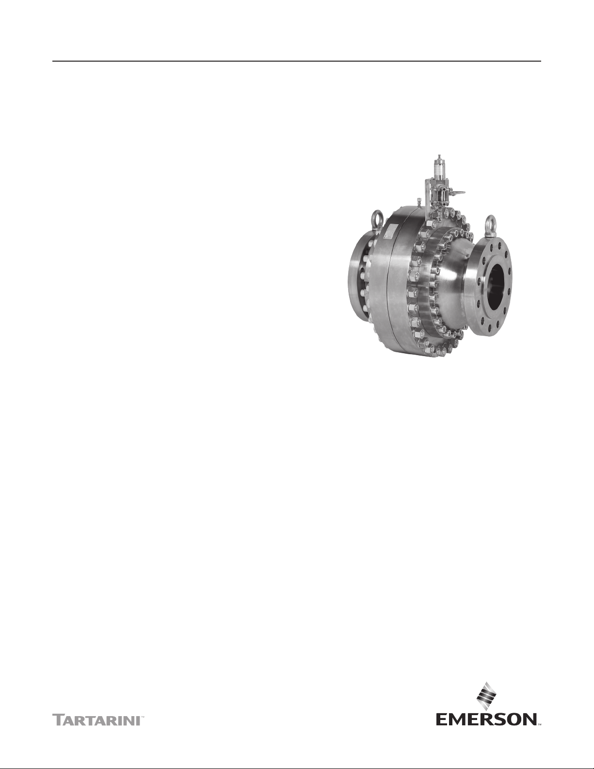
Figure 1. Type FL Regulator with Type PRX Pilot
• Disk Design—The FL series oers disks
for the main body made from Nitrile (NBR),
Fluorocarbon (FKM), and Polyurethane (PU).
Polyurethane (PU) provides better abrasion
resistance properties and a high durometer rating
to extend the working life of the disk in dicult
applications such as high pressure drop and
low ow.
Introduction
The Type FL is an accurate, pilot-operated regulator
designed for high-pressure transmission/city gate,
large capacity distribution systems and power plant
feeds. Type FL provides smooth and quiet operation,
tight shuto and long service life. The regulator is
comprised of a main valve actuator, a Type PRX
pressure reducing pilot and a Type SA/2 pilot supply
pressure regulator.
Type FL
North America Only
Page 2

Type FL
Specications
The Specifications section gives some general specifications for the Type FL regulators. The nameplates give
detailed information for a particular regulator as it comes from the factory.
Available Conguration
Type FL: Pilot-operated pressure reducing
regulator from 14.5 to 1160 psig / 1.00 to 80.0 bar
outlet pressures
Body Sizes
Type FL: NPS 1, 2, 3, 4, 6, 8 and 10 /
DN 25, 50, 80, 100, 150, 200 and 250
Type FL with Type SRS Silencer (Inlet x Outlet):
NPS 1 x 4, 2 x 6, 3 x 10, 4 x 10, 6 x 12 and 8 x 16 /
DN 25 x 100, 50 x 150, 80 x 250, 100 x 250,
150 x 300 and 200 x 400
Main Valve End Connection Style and
Pressure Ratings
CL300 RF: 740 psig / 51.0 bar
CL600 RF: 1480 psig / 102 bar
(1)
(3)
(3)
Maximum Inlet and Outlet (Casing) Pressure
1480 psig / 102 bar
(3)
Minimum Operating Dierential Pressure
Start Open:
NPS 1 to 4 / DN 25 to 100: 7.3 psid / 0.50 bar d
NPS 6 and 8 / DN 150 and 200: 3 psid / 0.21 bar d
NPS 10 / DN 250: 2.9 psid / 0.2 bar d
Full Open
NPS 1 to 4 / DN 25 to 100: 14.5 psid / 1.00 bar d
NPS 6 and 8 / DN 150 and 200: 7.3 psid /
0.50 bar d
NPS 10 / DN 250: 8.7 psid / 0.6 bar d
Outlet (Control) Pressure Ranges
See Table 1
Flow and Coecients
See Table 2
Pilot and Filter-Regulator Flow Coecients
Type PRX Pilot: C
: 10.5; Cv: 0.36; C1: 29
g
Type SA/2 Filter-Regulator: Cg: 19
Pressure Registration
External
Process Temperature Capabilities
(1)(2)
Nitrile (NBR), Fluorocarbon (FKM) or
Polyurethane (PU) Disk
ANSI/FCI 70-3 Class VIII: -4 to 140°F / -20 to 60°C
Nitrile (NBR) or Polyurethane (PU) Disk
ANSI/FCI 70-3 Class VI: -20 to 140°F / -29 to 60°C
Approximate Weights (Including Pilot)
See Figure 7
(1)
Construction Materials
Type FL Main Valve
Main Body and Flanges: Steel
Sleeve and Disk Holder: Steel
Diaphragm Plates: Steel
Diaphragm: Nitrile (NBR) with PVC coating
Disk O-rings: Nitrile (NBR) or Fluorocarbon (FKM)
Disk: Nitrile (NBR), Fluorocarbon (FKM)
or Polyurethane (PU)
North America Only
Type PRX Pilot
Body: Steel
Trim: Stainless steel
Diaphragm: Nitrile (NBR) or Fluorocarbon (FKM)
Disk O-rings: Nitrile (NBR) or Fluorocarbon (FKM)
Disk: Polyurethane (PU) or Fluorocarbon (FKM)
Type SA/2 Supply Pressure Regulator
Body: Steel
Diaphragm: Nitrile (NBR) with PVC Coating
O-rings: Nitrile (NBR) or Fluorocarbon (FKM)
Disk: Polyurethane (PU) or Fluorocarbon (FKM)
1. The pressure/temperature limits in this Bulletin and any applicable standard or code limitation should not be exceeded.
2. Types PRX and SA/2 Fluorocarbon (FKM) elastomer are limited to 0°F / -18°C.
3. At average ambient temperature.
2
Page 3
Type FL
E0822
TYPE SR
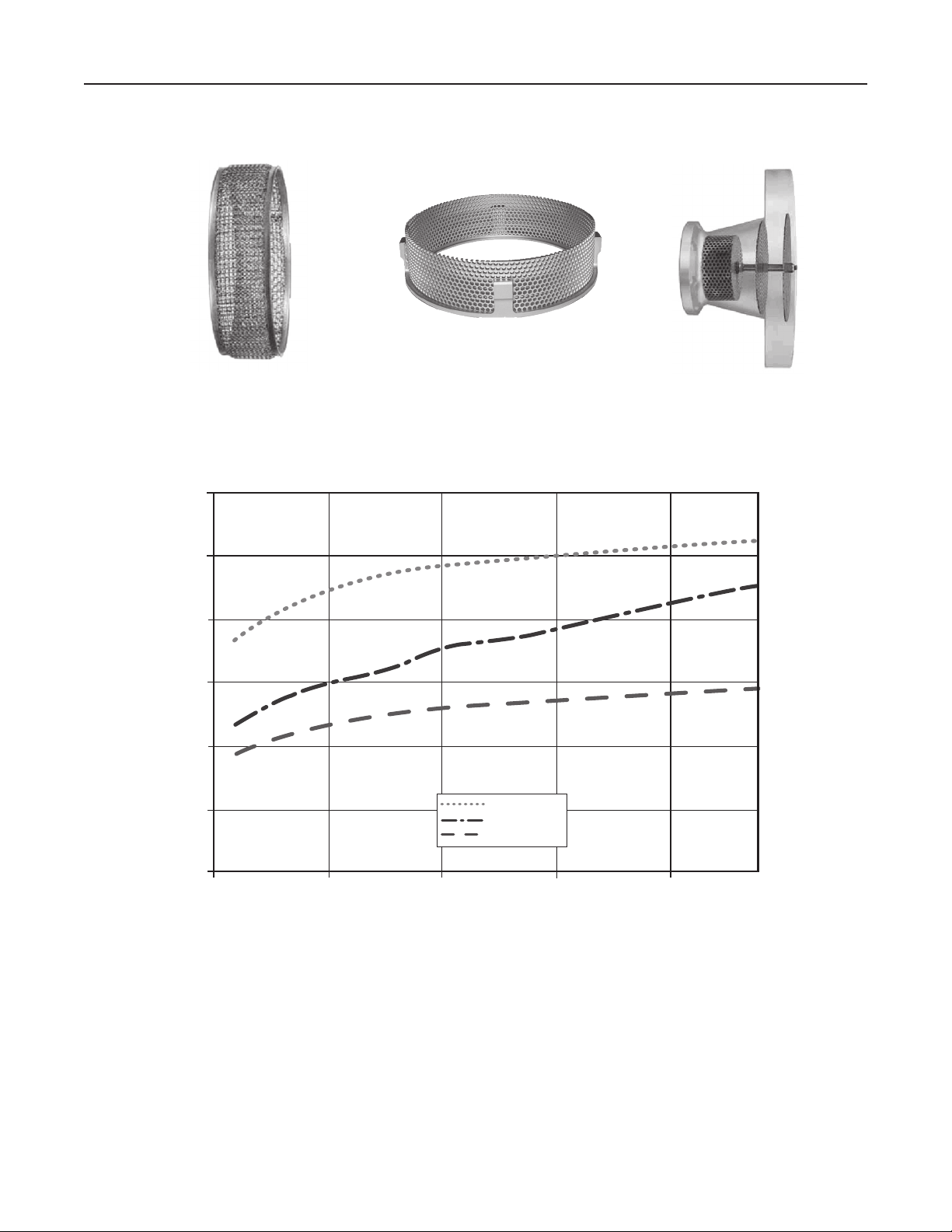
Figure 2. Noise Abatement Construction
110
100
90
80
NOISE, dB (A)
70
60
TYPE SRII
STANDARD
TYPE SR OR SRII
TYPE SRS
TYPE SRS
North America Only
50
0
187,567 /
5000
373,134 /
10,000
FLOW RATE IN SCFH / Nm3/h
559,701 /
15,000
Figure 3. Typical Sound Emission Comparison among the Different Configurations
746,269 /
20,000
3
Page 4

Type FL
The regulator’s superior performance is due to the
amplifying eect of the pilot and two-path control system.
Changes in outlet pressure act quickly on the actuator
diaphragm to provide fast response to system change.
Then the pilot amplies any small system changes to
position the main valve for precise pressure control.
Type PRX Pilot Descriptions
The Type FL pressure reducing regulators include a
PRX Series pilot mounted on the main valve.
Type PRX/120: Outlet pressure range of 14.5 to
435 psig / 1.00 to 30.0 bar. Type PRX/120 can be
used as the pilot on single stage pressure-reducing
regulators, as the monitor or working pilot in wide-open
monitor systems or as the working pilots in working
monitor systems.
Type PRX/120-AP: Outlet pressure range of 435 to
1160 psig / 30.0 to 80.0 bar. The Type PRX/120-AP
can be used as the pilot on single stage pressurereducing regulators, as the monitor or working pilot in
wide-open monitor systems or as the working pilots in
working monitor systems.
Type PRX/125: This pilot is identical to the
Type PRX/120 except that the restriction screw is
removed. Type PRX/125 can only be used as the
monitor override pilot on working monitor applications.
Type PRX/125-AP: Identical to the Type PRX/120-AP
except that the restriction screw is removed.
Type PRX/125-AP can only be used as the monitor
override pilot on working monitor applications.
Type PRX/131: Outlet pressure range of 14.5 to
435 psig / 1 to 30 bar. The Type PRX/131 is used as a
booster or quick dump pilot on a single stage pressure
reducing regulator or with the monitor pilot on the
monitor regulator in Wide-Open Monitor systems. It
is installed as standard on the regulator for NPS 10 /
DN 250 and can be used on any other size to increase
its closing speed.
Type SA/2 has an integral 5 micron lter. This integral
lter acts only as an emergency lter; gas must be
cleaned upstream of the regulator.
Noise Abatement
At elevated pressure drops and ow rates, regulators
with standard trims can produce unacceptable noise
levels. Several options are available to reduce the
noise generated.
Type SR: Type SR (Figure 2) multi-path noise
abatement device is incorporated into the regulator
on the seat area. It consists of plated Stainless steel
wires containing no sound deadening materials.
Depending on ows and pressure drop, the silencer
can reduce noise levels as much as 20 dB (A) with an
approximate 3% Cg reduction. Type SR is available
only in NPS 1 through 6 / DN 25 through 150 and is
not recommended for high velocity applications.
Type SRII: The Type SRII (Figure 2) noise abatement
device is the next generation of Type SR and is
used in case of extreme service conditions (dirty
gas, high pressure drops and high gas velocities).
Noise characteristics are very similar to the standard
Type SR.
Type SRS: A second noise reduction device may be
added to the Type FL regulators. Type SRS (Figure 2)
consists of a Type SR or SRII plus a widened outlet
ange in which a second silencer is tted. Noise
reduction is based on the principle of stream splitting
and gradual expansion in several stages. By using a
wider outlet ange the silencer can be mounted integral
to the regulator body which allows installation of the
regulator directly into the downstream piping without
an expansion joint. Noise reduction up to 25 dB (A)
is reached without limiting the velocity in the outlet
ange with a Cg reduction of about 15%. Type SR/SRS
Silencer is available only in NPS 1 through 6 / DN 25
through 150.
North America Only
Type PRX/131-AP: Outlet pressure range of 435
to 1160 psig / 30 to 80 bar. This pilot is used as a
booster or quick dump pilot on a single stage pressure
reducing regulator or with a monitor pilot on the
monitor regulator in Wide-Open Monitor systems.
Type SA/2 Pilot Supply Filter Regulator
The PRX Series pilots are usually used together
with the Type SA/2 pilot supply lter regulator. The
Type SA/2 acts as a pressure stabilizer that provides a
constant supply pressure to the PRX Series pilots: that
is approximately 45 psi / 3.1 bar over set pressure.
4
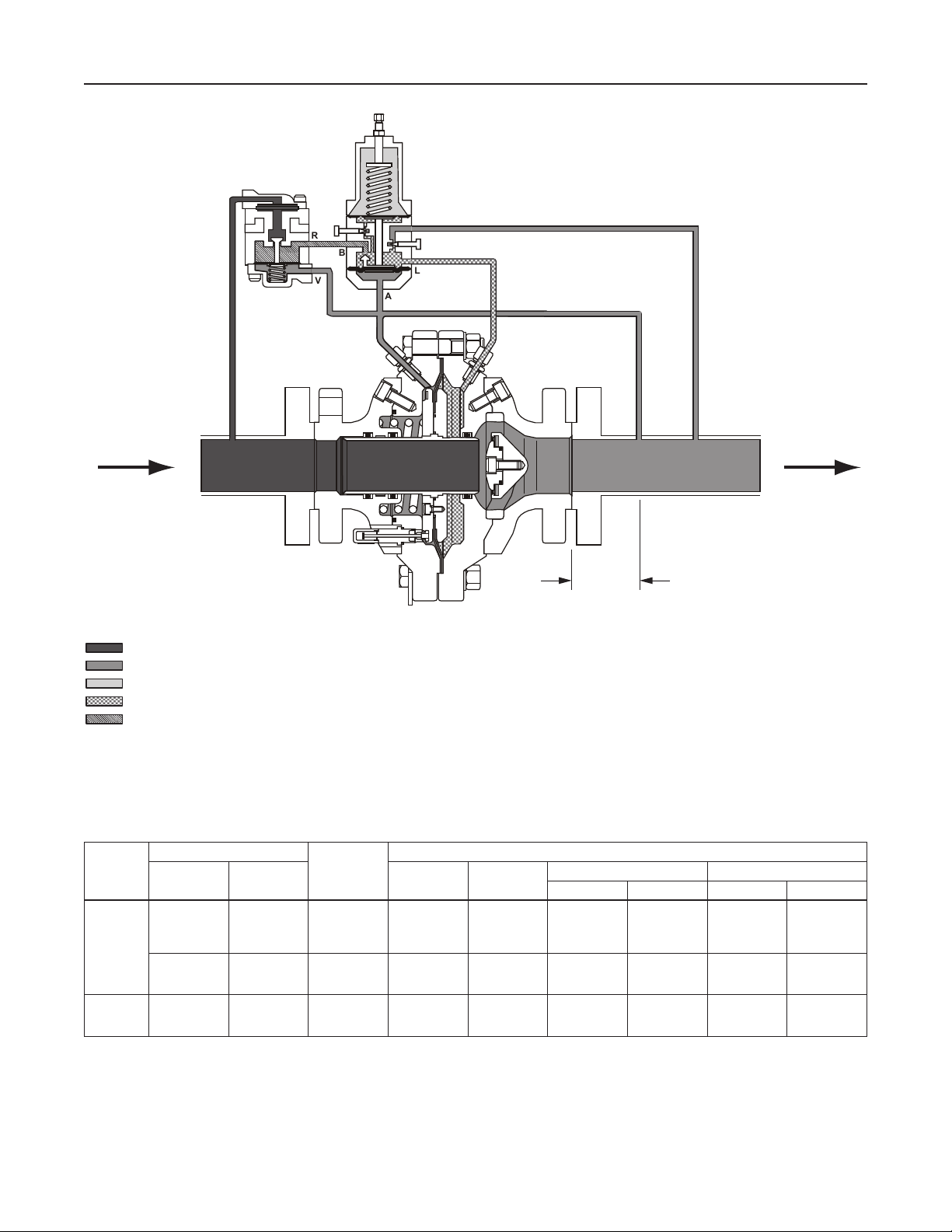
Principle of Operation
The pilot-operated Type FL (Figure 4) uses inlet
pressure as the operating medium, which is reduced
through pilot operation to load the actuator diaphragm.
Outlet pressure opposes loading pressure in the
actuator and also opposes the pilot control spring.
When outlet pressure drops below the setting of the
pilot control spring, pilot control spring force on the
pilot diaphragm opens the pilot valve plug, providing
additional loading pressure to the actuator diaphragm.
Page 5
Type FL
TYPE
TYPE
SA/2
M
R
B
V
PRX/120
S
L
A
E0827_01/2016
INLET PRESSURE
OUTLET PRESSURE
ATMOSPHERIC PRESSURE
LOADING PRESSURE
PILOT SUPPLY PRESSURE
Figure 4. Type FL Operational Schematic
Table 1. Outlet (Control) Pressure Ranges
OUTLET PRESSURE RANGE
TYPE
PRX/120
PRX/125
PRX/131
PRX-AP/120
PRX-AP/125
PRX-AP/131
psig bar Spring Color Part Number
14.5 to 26
23 to 44
41 to 80
73 to 123
116 to 210
203 to 334
319 to 435
435 to 1160 30.0 to 80.0 1% Clear M0273790X12 0.335 0.85 3.93 10.0
1.00 to 1.8
1.6 to 3.0
2.8 to 5.5
5.0 to 8.5
8.0 to 14.5
14.0 to 23.0
22.0 to 30.0
(ACCURACY
AC
CLASS)
2.5%
2.5%
2.5%
2.5%
1%
1%
1%
TYPE FL
Yellow
Green
Blue
Black
Silver
Gold
Aluminum
M0255240X12
M0255230X12
M0255180X12
M0255220X12
M0255210X12
M0255200X12
M0255860X12
8 TO 10
PIPE
DIAMETER
PILOT CONTROL SPRING INFORMATION
Wire Diameter Free Length
In. cm In. cm
0.110
0.126
0.138
0.157
0.177
0.197
0.236
0.28
0.32
0.35
0.40
0.45
0.50
0.60
2.16 5.49
2.16
2.00
2.00
5.49
5.10
5.10
North America Only
5
Page 6
Type FL
M1204_01/2016
M
M
TYPE
SA/2
TYPE
SA/2
R
V
TYPE
PRX/125
R
B
V
TYPE
PRX/120
S
B
L
A
TYPE
SA/2
M
R
V
TYPE
PRX/120
S
B
L
A
8 TO 10
PIPE
DIAMETER
TYPE FL WIDE-OPEN MONITOR
TYPE
PRX/120
S
B
L
A
S
L
A
TYPE
SA/2
M
R
V
TYPE
PRX/120
S
B
L
A
M1201_01/2016
INLET PRESSURE
OUTLET PRESSURE
ATMOSPHERIC PRESSURE
LOADING PRESSURE
INTERMEDIATE PRESSURE
PILOT SUPPLY PRESSURE
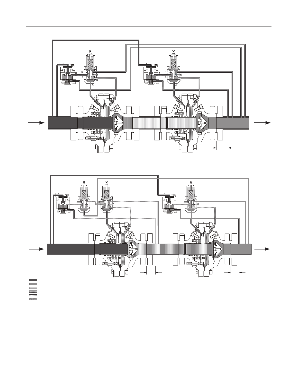
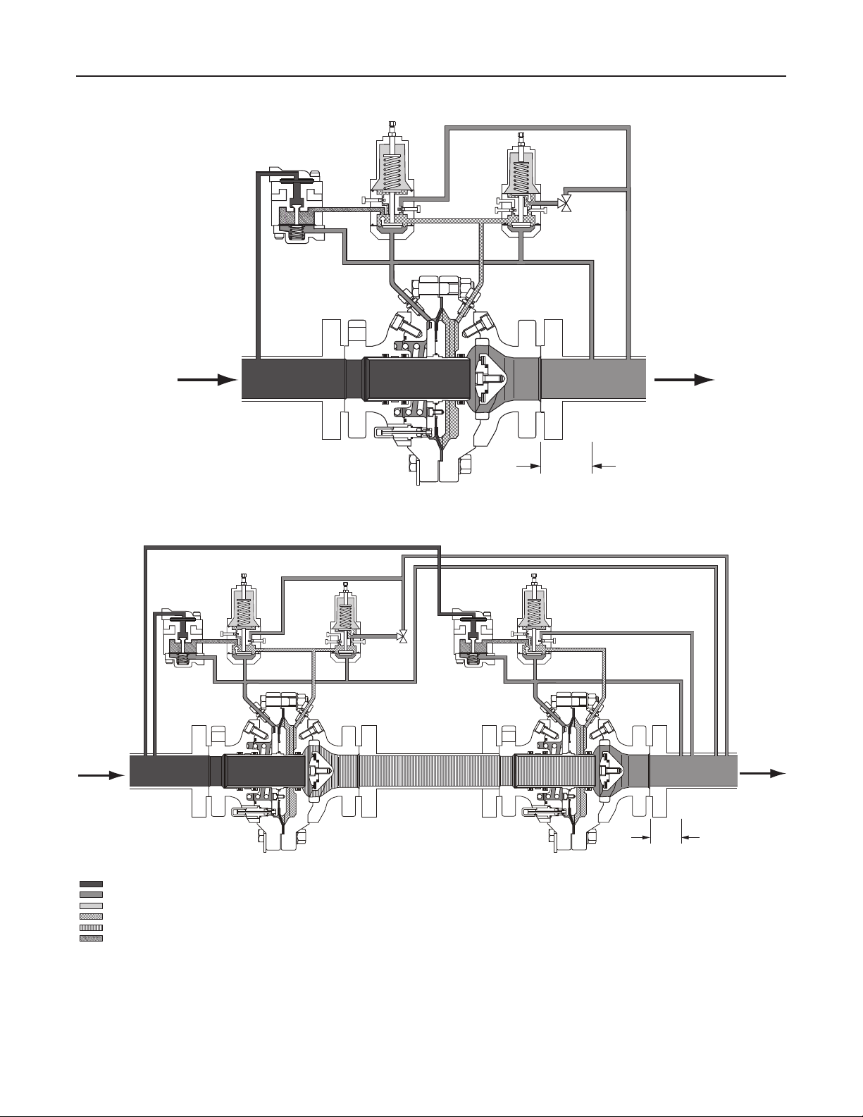
Figure 5. Typical FL Installation Schematics
8 TO 10
PIPE
DIAMETER
TYPE FL WORKING MONITOR WITH TYPE PRX-125
North America Only
8 TO 10
PIPE
DIAMETER
6
Page 7
Type FL
TYPE
PRX/120
TYPE
SA/2
M
TYPE
PRX/131
M1216_01/2016
R
B
V
S
L
A
S
L
B
A
8 TO 10
PIPE
DIAMETER
TYPE FL WITH TYPE PRX/131 QUICK DUMP PILOT
TYPE
PRX/120
TYPE
SA/2
M
R
V
S
B
L
A
TYPE
PRX/131
S
B
L
A
TYPE
SA/2
M
R
V
TYPE
PRX/120
S
B
L
A
North America Only
M1212_01/2016
INLET PRESSURE
OUTLET PRESSURE
ATMOSPHERIC PRESSURE
LOADING PRESSURE
INTERMEDIATE PRESSURE
PILOT SUPPLY PRESSURE
TYPE FL WIDE-OPEN MONITOR WITH TYPE PRX/131 QUICK DUMP PILOT
Figure 5. Typical FL Installation Schematics (continued)
8 TO 10
PIPE
DIAMETER
7
Page 8

Type FL
This diaphragm loading pressure opens the main valve
plug, supplying the required ow to the downstream
system. Any excess loading pressure on the actuator
diaphragm escapes downstream through the exhaust
restriction in the pilot.
When the gas demand in the downstream system
has been satised, the outlet pressure increases.
The increased pressure is transmitted through
the downstream control line and acts on the pilot
diaphragm. This pressure exceeds the pilot spring
setting and moves the diaphragm, closing the orice.
The loading pressure acting on the main diaphragm
bleeds to the downstream system through the
exhaust restriction in the pilot.
Installation
Type FL regulators are installed in a horizontal or
vertical pipeline. An optional outlet ange spacer
(Figure 6, page 8) is available to be installed
downstream of the regulator. Once the spacer and
outlet ange are removed, the disk holder and trim
parts are easily accessed. See Figure 5 for typical
piping installations. Dimensions are given in Figure 7.
Type FL may be installed in any position, but is
normally installed in a horizontal pipeline with the pilot
or pilots above the body. The optimal location for the
sense and bleed lines is between the Type FL and
the downstream block valve. If the sense and bleed
lines cannot be located between the Type FL and
downstream block valve, contact your local Sales
Oce for Startup assistance. See Figure 5 for typical
piping installation.
pressure at a higher value than normal pressure.
During an overpressure situation, monitoring keeps
the customer online. Also, testing is relatively easy
and safe. To perform a periodic test on a monitoring
regulator, increase the outlet set pressure of the
working regulator and watch the outlet pressure to
determine if the monitoring regulator takes over at the
appropriate outlet pressure.
Wide-Open Monitoring Systems
(Figure 5)
There are two types of wide-open monitoring systems:
upstream and downstream. The dierence between
upstream and downstream monitoring is that the
functions of the regulators (monitor and worker) are
reversed. Systems can be changed from upstream
to downstream monitoring and vice-versa, by simply
reversing the setpoints of the two regulators. The
decision to use either an upstream or downstream
monitoring system is largely a matter of personal
preference or company policy.
In normal operation of a wide-open conguration,
the working regulator controls the system’s outlet
pressure. With a higher outlet pressure setting, the
monitor regulator senses a pressure lower than its
setpoint and tries to increase outlet pressure by going
wide open. If the working regulator fails, the monitoring
regulator assumes control and holds the outlet
pressure at its outlet pressure setting.
Working Monitoring Regulators
(Figure 5)
North America Only
Note
To prevent damage to the pilot during
Startup, the sense and bleed lines
should be located on the same side of
the downstream block valve.
Monitoring Systems
Monitoring regulation is overpressure protection by
containment, therefore, there is no relief valve to vent
to the atmosphere. When the working regulator fails
to control the pressure, a monitor regulator installed in
series goes into operation to maintain the downstream
8
In a working monitoring system, the upstream regulator
requires two pilots and it is always the monitoring
regulator. The additional pilot permits the monitoring
regulator to act as a series regulator to control an
intermediate pressure during normal operation.
In this way, both units are always operating and can be
easily checked for proper operation.
In normal operation, the working regulator controls
the outlet pressure of the system. The monitoring
regulator’s working pilot controls the intermediate
pressure and the monitoring pilot senses the system’s
outlet pressure. If the working regulator fails, the
monitoring pilot will sense the increase in outlet
pressure and take control.
Page 9

DISK-HOLDER
Type FL
SPACER
OUTLET FLANGE
SOCKET HEAD SCREW
Figure 6. Outlet Flange Spacer Installation
WARNING
▲
The working regulator must be rated
for the maximum allowable operating
pressure of the system because this will
be its inlet pressure if the monitoring
regulator fails. Also, the outlet pressure
rating of the monitoring pilot and any
other components that are exposed to
the intermediate pressure must be rated
for full inlet pressure.
North America Only
O-RING
Working monitor installations require a Type FL main
valve with a Type PRX/120 or PRX-AP/120 working
pilot and a Type PRX/125 or PRX-AP/125 monitoring
pilot for the upstream regulator and a Type FL with
the appropriate Type PRX/120 or PRX-AP/120 pilot
for the downstream regulator.
9
Page 10

Type FL
Table 2. Flow and Sizing Coefficients
BODY
SIZE,
NPS / DN
Regulating Wide-open
C
g
1 / 25 590 18.4 610 18.9 32.1 0.65 0.73 0.89 550 16.4 570 16.9 33.5 0.71 0.69 0.89
2 / 50 2300 70.6 2400 72.7 32.6 0.67 0.69 0.89 2200 67.7 2300 69.7 32.5 0.67 0.68 0.89
3 / 80 5200 161.9 5400 166.8 32.1 0.69 0.70 0.89 4900 161.4 5000 166.3 30.4 0.58 0.70 0.89
4 / 100 8000 249.3 8200 256.8 32.1 0.65 0.65 0.89 7900 244.9 8100 252.2 32.3 0.66 0.64 0.89
6 / 150 20,300 735.8 20,900 757.8 27.6 0.48 0.71 0.89 18,400 666.7 19,000 686.7 27.6 0.48 0.67 0.89
8 / 200 30,900 1080.4 32,800 1112.8 28.6 0.52 0.66 0.89 30,600 1069.9 31,500 1102.0 28.6 0.52 0.65 0.89
10 / 250 52,100 1615.4 53,600 1663.9 32.3 0.66 0.69 0.89 51,500 1599.7 53,100 1647.7 32.2 0.66 0.69 0.89
1 / 25 580 17.4 600 17.9 33.4 0.70 0.89 0.89 530 15.5 550 15.9 34.3 0.74 0.84 0.89
2 / 50 2200 65.3 2300 67.2 33.7 0.72 0.84 0.89 2100 60.7 2200 62.6 34.6 0.76 0.81 0.89
3 / 80 5000 151.7 5200 156.3 33.0 0.69 0.85 0.89 4700 149.4 4800 153.9 31.5 0.63 0.84 0.89
4 / 100 7400 226.5 7600 233.3 32.7 0.67 0.78 0.89 7300 226.0 7500 232.8 32.3 0.66 0.77 0.89
6 / 150 17,800 597.5 18,300 615.4 29.8 0.56 0.80 0.89 16,900 567.1 17,400 584.1 29.8 0.56 0.78 0.89
1 / 25 570 15.6 590 16.0 36.6 0.85 0.84 0.89 500 13.5 520 13.9 37.0 0.87 0.78 0.89
2 / 50 1900 48.9 2000 50.4 38.9 0.95 0.73 0.89 1850 47.2 1900 48.6 39.2 0.97 0.71 0.89
3 / 80 4000 111. 7 4100 115.1 35.8 0.81 0.73 0.89 3800 104.8 3900 107.9 36.3 0.83 0.70 0.89
4 / 100 6200 164.7 6400 169.6 37.7 0.90 0.66 0.89 6100 170.6 6300 175.7 35.8 0.81 0.67 0.89
(1)
6 / 150
13,490 397.8 13,890 409.7 33.9 0.73 0.68 0.89 13,030 380.5 13,420 391.9 34.2 0.74 0.67 0.89
1 / 25 540 16.0 560 16.5 33.5 0.82 0.05 0.89 490 14.2 500 14.6 34.5 0.73 0.04 0.89
2 / 50 2000 59.8 2100 61.6 33.4 0.81 0.03 0.89 1900 55.6 2000 57.3 34.2 0.75 0.03 0.89
3 / 80 4400 138.0 4500 142.1 30.0 0.55 0.03 0.89 4200 143.7 4300 148.0 29.3 0.54 0.03 0.89
4 / 100 6500 196.5 6700 202.4 32.9 0.69 0.02 0.89 6400 203.9
6 / 150 16,200 480.7 16,700 495.1 31.7 0.65 0.02 0.89 15,400 500.7 15,800 515.7 30.7 0.60 0.02 0.89
8 / 200 25,335 784.0 26,100 807.5 32.3 0.66 0.01 0.89 24,200 749.1 24,900 771.6 32.3 0.66 0.01 0.89
10 / 250 42,500 1197.9 43,800 1233.8 35.5 0.8 0.01 0.89 40,600 1144.6 41,800 1178.9 35.5 0.8 0.01 0.89
1 / 25 530 14.3 550 14.7 37.1 0.99 0.04 0.89 520 15.2 540 15.7 33.9 0.89 0.04 0.89
2 / 50 1700 44.8 1800 46.1 38.0 0.98 0.03 0.89 1700 43.2 1800 44.5 39.4 0.96 0.03 0.89
3 / 80 3500 101.6 3600 104.6 34.4 0.65 0.02 0.89 3400 100.8 3500 103.8 33.7 0.71 0.02 0.89
4 / 100 5400 142.9 5600 147.2 37.8 0.93 0.02 0.89 5300 153.9 5500 158.5 34.4 0.77 0.02 0.89
(1)
6 / 150
12,830 374.9 13,220 386.1 34.2 0.74 0.01 0.89 12,310 355.7 12,680 366.4 34.6 0.76 0.02 0.89
8 / 200 20,100 515.0 20,700 530.5 39.0 0.96 0.01 0.89 19,200 492.1 19,800 506.9 39.0 0.66 0.01 0.89
1. Sizing values reect current 6-bolt Type SRS design. See previous document revisions for information on obsolete 1-bolt Type SRS design.
LINE SIZE EQUALS BODY SIZE 2:1 LINE SIZE TO BODY SIZE RATIO
IEC Sizing Coecients Regulating Wide-open
C
C
v
C
C
g
1
X
F
F
v
T
D
C
L
C
g
C
v
g
Type FL
Type FL-SR
Type FL-SR/SRS
Type FL-SRII
6600 210.0 31.5 0.63 0.02 0.89
Type FL-SRII/SRS
IEC Sizing
C
C
1
v
Coecients
XTFDF
L
North America Only
10
Page 11

Type FL
Table 3. Capacities for Type FL with PRX Series Pilot and Type SA/2 Pilot Supply Filter Regulator with 1:1 Line Size to Body Size Ratio
INLET
PRESSURE
psig bar psig bar
30 2.1 15 1.0 30 0.8 11 5 3.1 262 7.0 404 10.8 1105 29.6 1656 44.4 2637 70.7
40 2.8
50 3.4
60 4.1
75 5.2
100 6.9
125 8.6
150 10.3
200 13.8
300 20.7
400 27.6
500 34.5
600 41.4
700 48.3
OUTLET
PRESSURE
NPS 1 /
DN 25 Body
SCFH Nm
15 1.0 39 1.1 153 4.1 347 9.3 534 14.3 1415 37.9 2140 57.3 3489 93.5
25 1.7 34 0.9 132 3.5 302 8.1 465 12.5 1291 34.6 1927 51.6 3028 81.2
15 1.0 48 1.3 186 5.0 423 11.3 651 17.4 1685 45.1 2564 68.7 4254 11 4
25 1.7 45 1.2 174 4.7 395 10.6 609 16.3 1643 44.0 2472 66.2 3968 106
35 2.4 38 1.0 148 4.0 337 9.0 519 13.9 1457 39.0 2168 58.1 3379 90.6
up to 16 up to 1.1 56 1.5 218 5.8 494 13.2 760 20.4 1939 52.0 2962 79.4 4965 133
20 1.4 55 1.5 215 5.8 488 13.1 751 20.1 1947 52.2 2961 79.4 4904 131
30 2.1 52 1.4 203 5.4 461 12.4 710 19.0 1909 51.2 2875 77.1 4626 124
45
up to 22 up to 1.5 67 1.8 262 7.0 594 15.9 913 24.5 2330 62.4 3560 95.4 5964 160
30 2.1 66 1.8 255 6.8 581 15.6 893 23.9 2339 62.7 3548 95.1 5826 156
40 2.8 62 1.7 242 6.5 550 14.7 847 22.7 2285 61.2 3438 92.1 5515 148
60 4.1 47 1.3 181 4.8 414 11.1 637 17.1 1813 48.6 2687 72.0 4135 111
up to 32 up to 2.2 86 2.3 335 9.0 760 20.4 1169 31.3 2982 79.9 4556 122 7629 204
40 2.8 85 2.3 329 8.8 748 20.0 1151 30.8 2995 80.3 4551 122 7502 201
50 3.4 82 2.2 318 8.5 723 19.4 1112 29.8 2966 79.5 4476 120 7242 194
85 5.9 54 1.5 209 5.6 478 12.8 736 19.7 2113 56.6 3126 83.8 4777 128
up to 43 up to 3.0 105 2.8 408 10.9 925 24.8 1424 38.2 3637 97.5 5555 149 9282 249
50 3.4 104 2.8 403 10.8 915 24.5 1408 37.7 3650 97.8 5552 149 9174 246
75 5.2 95 2.6 368 9.9 839 22.5 1291 34.6 3513 94.1 5272 141 8393 225
110 7.6 61 1.6 234 6.3 535 14.3 824 22.1 2378 63.7 3513 94.1 5344 143
up to 52 up to 3.6 124 3.3 482 12.9 1093 29.3 1681 45.1 4285 11 5 6549 176 10,959 294
75 5.2 119 3.2 461 12.4 1048 28.1 1613 43.2 4280 11 5 6469 173 10,498 281
95 6.6 110 3.0 425 11.4 970 26.0 1493 40.0 4087 11 0 6124 164 9701 260
130 9.0 76 2.0 291 7.8 666 17.8 1025 27.5 2948 79.0 4359 117 6646 178
up to 73 up to 5.0 162 4.3 628 16.8 1424 38.2 2192 58.7 5592 150 8544 229 14,277 383
100 6.9 156 4.2 604 16.2 1374 36.8 2114 56.6 5591 150 8457 227 13,749 368
125 8.7 145 3.9 562 15.1 1281 34.3 1972 52.8 5378 144 8068 216 12,812 343
185 12.8 77 2.1 296 7.9 679 18.2 1045 28.0 3040 81.5 4481 120 6771 181
up to 115 up to 7.9 237 6.3 920 24.7 2088 55.9 3212 86.1 8205 220 12,533 336 20,913 560
150 10.3 230 6.2 890 23.8 2023 54.2 3113 83.4 8212 220 12,432 333 20,246 543
200 13.8 208 5.6 801 21.5 1828 49.0 2813 75.4 7733 207 11,575 310 18,263 489
275 19.0 120 3.2 461 12.3 1055 28.3 1625 43.5 4716 126 6956 186 10,525 282
up to 155 up to 10.7 312 8.4 1214 32.5 2753 73.8 4236 11 4 10,812 290 16,518 443 27,573 739
200 13.8 303 8.1 1176 31.5 2673 71.6 4113 110 10,832 290 16,404 440 26,739 717
250 17.2
300 20.7 250 6.7 963 25.8 2200 59.0 3386 90.8 9482 254 14,122 379 21,964 589
350 24.1 190 5.1 731 19.6 1673 44.8 2575 69.0 7409 199 10,953 294 16,682 447
up to 196 up to 13.5 388 10.4 1507 40.4 3417 91.6 5258 141 13,422 360 20,506 550 34,221 917
225 15.5 383 10.3 1486 39.8 3375 90.4 5193 139 13,478 361 20,495 549 33,775 905
300 20.7 359 9.6 1389 37.2 3163 84.8 4868 131 13,145 352 19,771 530 31,612 847
400 27.6 286 7.7 1103 29.6 2522 67.6 3882 104 10,988 295 16,317 437 25,165 674
up to 237 up to 16.3 463 12.4 1800 48.2 4082 109 6280 168 16,033 430 24,493 656 40,869 1095
300 20.7 451 12.1 1747 46.8 3971 106 6111 164 16,070 431 24,348 653 39,724 1065
375 25.9 422 11.3 1632 43.7 3719 99.7 5724 153 15,547 417 23,347 626 37,161 996
450 31.0 372 10.0 1434 38.4 3276 87.8 5041 135 14,108 378 21,014 563 32,694 876
500 34.5 319 8.6 1228 32.9 2809 75.3 4324 116 12,327 330 18,270 490 28,021 751
up to 278 up to 19.2
300 20.7 535 14.3 2078 55.7 4717 126 7258 195 18,699 501 28,493 764 47,210 1265
350 24.1 525 14.1 2033 54.5 4621 124 7110 191 18,689 501 28,319 759 46,216 1239
400 27.6 508 13.6 1966 52.7 4476 120 6888 185 18,450 495 27,812 745 44,738 1199
550 37.9 410 11.0 1578 42.3 3606 96.6 5551 149 15,656 420 23,270 624 35,983 964
600 41.4 349 9.3 1342 36.0 3071 82.3 4726 127 13,543 363 20,045 537 30,622 821
3.1 42 1.1 162 4.3 370 9.9 569 15.2 1608 43.1 2388 64.0 3699 99.1
284 7.6 1097 29.4 2501 67.0 3848 103 10,464 280 15,709 421 24,989 670
539 14.4
CAPACITIES IN THOUSANDS OF SCFH / Nm3/h OF 0.6 SPECIFIC GRAVITY NATURAL GAS
NPS 2 /
DN 50 Body
3
/h SCFH Nm3/h SCFH Nm3/h SCFH Nm3/h SCFH Nm3/h SCFH Nm3/h SCFH Nm3/h
2093 56.1 4746 127 7303 196 18,643 500 28,480 763 47,517 1273
NPS 3 /
DN 80 Body
NPS 4 /
DN 100 Body
NPS 6 /
DN 150 Body
NPS 8 /
DN 200 Body
NPS 10 /
DN 250 Body
North America Only
- continued -
11
Page 12

Type FL
Table 3. Capacities for Type FL with PRX Series Pilot and Type SA/2 Pilot Supply Filter Regulator with 1:1 Line Size to Body Size
Ratio (continued)
INLET
PRESSURE
psig bar psig bar
800 55.2
900 62.1
1000 69.0
1100 75.8
1200 82.7
1300 89.6
1400 96.5
1480 102
OUTLET
PRESSURE
NPS 1 /
DN 25 Body
SCFH Nm
up to 300 up to 20.7 616 16.5 2395 64.2 5430 146 8355 224 21,179 568 32,419 869 54,374 1457
350 24.1 609 16.3 2365 63.4 5368 144 8260 221 21,327 572 32,477 870 53,720 1440
400 27.6 598 16.0 2318 62.1 5270 141 8109 217 21,307 571 32,290 865 52,707 1413
450 31.0 582 15.6 2254 60.4 5129 138 7893 212 21,089 565 31,813 853 51,272 1374
500 34.5 561 15.0 2167 58.1 4938 132 7599 204 20,630 553 30,984 830 49,332 1322
650 44.8 444 11.9 1710 45.8 3911 105 6019 161 17,078 458 25,344 679 39,011 1045
up to 350 up to 24.1 691 18.5 2684 71.9 6086 163 9364 251 23,827 639 36,433 976 60,929 1633
400 27.6 683 18.3 2651 71.1 6019 161 9261 248 23,952 642 36,458 977 60,226 1614
500 34.5 656 17.6 2541 68.1 5782 155 8898 239 23,723 636 35,806 960 57,797 1549
600 41.4 609 16.3 2353 63.1 5366 144 8259 221 22,648 607 33,921 909 53,591 1436
800 55.2 402 10.8 1545 41.4 3538 94.8 5445 146 15,707 421 23,207 622 35,269 945
up to 350 up to 24.1 770 20.6 2995 80.3 6785 182 10,440 280 26,244 703 40,266 1079 67,954 1821
400 27.6 765 20.5 2972 79.6 6740 181 10,371 278 26,470 709 40,440 1084 67,472 1808
500 34.5 746 20.0 2890 77.4 6568 176 10,107 271 26,544 7 11 40,232 1078 65,690 1760
600 41.4 711 19.1 2748 73.7 6260 168 9634 258 25,979 696 39,089 1048 62,550 1676
800 55.2 568 15.2 2187 58.6 5001 134 7697 206 21,774 584 32,338 867 49,886 1337
up to 350 up to 24.1 848 22.7 3301 88.5 7472 200 11,496 308 28,605 767 44,016 1180 74,857 2006
450 31.0 839 22.5 3259 87.4 7394 198 11,377 305 29,109 780 44,441 1191 74,007 1983
500 34.5 831 22.3 3223 86.4 7319 196 11,263 302 29,199 783 44,415 1190 73,230 1963
600 41.4 804 21.6 3114 83.5 7085 190 10,903 292 28,983 777 43,781 1173 70,826 1898
800 55.2 698 18.7 2691 72.1 6144 165 9456 253 26,306 705 39,246 1052 61,326 1644
1000 69.0 449 12.0 1725 46.2 3951 106 6081 163 17,616 472 25,997 697 39,380 1055
up to 350 up to 24.1 925 24.8 3603 96.6 8151 218 12,540 336 30,928 829 47,710 1279 81,673 2189
500 34.5 913 24.5 3547 95.1 8047 216 12,382 332 31,744 851 48,437 1298 80,535 2158
600 41.4 893 23.9 3461 92.8
800 55.2 810 21.7 3129 83.9 7135 191 10,981 294 30,105 807 45,093 1209 71,253 1910
1100 75.8 471 12.6 1808 48.5 4142 111 6376 171 18,499 496 27,289 731 41,285 1106
up to 350 up to 24.1 1001 26.8 3902 105 8823 237 13,573 364 33,224 890 51,362 1377 88,428 2370
500 34.5 994 26.6 3863 104 8758 235 13,475 361 34,214 917 52,347 1403 87,675 2350
600 41.4 978 26.2 3795 102 8619 231 13,263 356 34,443 923 52,367 1403 86,227 2311
800 55.2 913 24.5 3528 94.6 8038 215 12,369 332 33,477 897 50,321 1349 80,297 2152
1160 80.0 571 15.3 2195 58.8 5027 135 7738 207 22,334 599 32,992 884 50,112 1343
up to 350 up to 24.1 1077 28.9 4199 11 3 9490 254 14,600 391 35,498 951 54,984 1474 95,154 2550
500 34.5 1073 28.8 4174 11 2 9457 253 14,550 390 36,628 982 56,177 1506 94,696 2538
600 41.4 1061 28.4 4121 11 0 9351 251 14,389 386 37,009 992 56,419 1512 93,576 2508
800 55.2 1008 27.0 3902 105 8882 238 13,669 366 36,575 980 55,149 1478 88,769 2379
1160 80.0 747 20.0 2875 77.1 6576 176 10,122 271 28,813 772 42,721 1145 65,585 1758
up to 350 up to 24.1 1137 30.5 4436 11 9 10,022 269 15,417 413 37,307 1000 57,865 1551 100,535 2694
500 34.5 1136 30.4 4420 11 8 10,009 268 15,400 413 38,530 1033 59,196 1587 100,246 2687
600 41.4 1126 30.2 4376 11 7 9926 266 15,272 409 39,010 1046 59,584 1597 99,343 2662
800 55.2 1082 29.0 4189 11 2 9529 255 14,664 393 38,913 1043 58,810 1576 95,257 2553
1160 80.0 863 23.1 3325 89.1 7599 204 11,696 314 32,960 883 49,003 1313 75,813 2032
CAPACITIES IN THOUSANDS OF SCFH / Nm3/h OF 0.6 SPECIFIC GRAVITY NATURAL GAS
NPS 2 /
DN 50 Body
3
/h SCFH Nm3/h SCFH Nm3/h SCFH Nm3/h SCFH Nm3/h SCFH Nm3/h SCFH Nm
NPS 3 /
DN 80 Body
7867 211 12,105 324 31,782 852 48,174 1291 78,672 2108
NPS 4 /
DN 100 Body
NPS 6 /
DN 150 Body
NPS 8 /
DN 200 Body
NPS 10 /
DN 250 Body
3
/h
North America Only
12
Page 13

Type FL
Table 4. Capacities for Type FL-SR with PRX Series Pilot and Type SA/2 Pilot Supply Filter Regulator with 1:1 Line Size to Body Size Ratio
INLET
PRESSURE
psig bar psig bar
30 2.1 15 1.0 29 0.8 108 2.9 249 6.7 370 9.9 935 25.1
40 2.8
50 3.4
60 4.1
75 5.2
100 6.9
125 8.6
150 10.3
200 13.8
300 20.7
400 27.6
500 34.5
600 41.4
700 48.3
OUTLET
PRESSURE
SCFH Nm
15 1.0 38 1.0 144 3.9 330 8.8 490 13.1 1220 32.7
25 1.7 33 0.9 124 3.3 285 7.6 425 11.4 1084 29.0
15 1.0 47 1.3 176 4.7 404 10.8 599 16.1 1471 39.4
25 1.7 43 1.2 163 4.4 375 10.1 558 14.9 1401 37.6
35
up to 16 up to 1.1 55 1.5 206 5.5 472 12.7 700 18.8 1707 45.7
20 1.4 54 1.4 203 5.4 466 12.5 691 18.5 1699 45.5
30 2.1 50 1.3 190 5.1 438 11.7 651 17.4 1632 43.7
45 3.1 40 1.1 151 4.0 348 9.3 519 13.9 1337 35.8
up to 22 up to 1.5 66 1.8 248 6.7 567 15.2 842 22.6 2051 55.0
30 2.1 64 1.7 241 6.5 553 14.8 821 22.0 2029 54.4
40 2.8 60 1.6 227 6.1 522 14.0 776 20.8 1950 52.2
60 4.1 45 1.2 168 4.5 389 10.4 580 15.6 1501 40.2
up to 32 up to 2.2 84 2.3 318 8.5 727 19.5 1078 28.9 2626 70.4
40 2.8 82 2.2 311 8.3 713 19.1 1058 28.4 2608 69.9
50 3.4 79 2.1 299 8.0 687 18.4 1021 27.4 2547 68.3
85 5.9 52 1.4 194 5.2 450 12.1 671 18.0 1742 46.7
up to 43 up to 3.0 102 2.7 387 10.4 884 23.7 1312 35.2 3199 85.7
50 3.4 101 2.7 381 10.2 873 23.4 1295 34.7 3185 85.3
75 5.2 92 2.5 345 9.3 795 21.3 1182 31.7 2983 79.9
110 7.6 58 1.5 217 5.8 503 13.5 750 20.1 1955 52.4
up to 52 up to 3.6 121 3.2 457 12.2 1045 28.0 1549 41.5 3774 101
75 5.2 115 3.1 434 11.6 997 26.7 1481 39.7 3686 98.8
95 6.6 106 2.8 399 10.7 918 24.6 1366 36.6 3459 92.7
130
up to 73 up to 5.0 157 4.2 595 16.0 1362 36.5 2019 54.1 4922 132
100 6.9 151 4.0 569 15.3 1307 35.0 1941 52.0 4823 129
125 8.7 140
185 12.8 73 2.0 275 7.4 637 17.1 951 25.5 2488 66.7
up to 115 up to 7.9 231 6.2 872 23.4 1995 53.5 2959 79.3 7218 193
150 10.3 222 6.0 839 22.5 1926 51.6 2860 76.6 7096 190
200 13.8 199 5.3 750 20.1 1730 46.4 2574 69.0 6530 175
275 19.0 114 3.0 427 11.5 991 26.6 1479 39.6 3865 104
up to 155 up to 10.7 304 8.2 1151 30.8 2632 70.5 3903 105 9516 255
200 13.8 294 7.9 1109 29.7 2544 68.2 3778 101 9367 251
250 17.2 273 7.3 1029 27.6 2370 63.5 3525 94.5 8889 238
300 20.7 239 6.4 899 24.1 2077 55.7 3093 82.9 7926 212
350 24.1 180 4.8 679 18.2 1573 42.2 2345 62.9 6100 164
up to 196 up to 13.5 378 10.1 1429 38.3 3267 87.5 4845 130 11,813 317
225 15.5 372 10.0 1405 37.7 3219 86.3 4777 128 11,751 315
300 20.7 346 9.3 1304 35.0 3001 80.4 4461 120 11,210 300
400 27.6 273 7.3 1028 27.5 2377 63.7 3542 94.9 9130 245
up to 237 up to 16.3 451 12.1 1706 45.7 3902 105 5787 155 14,109 378
300 20.7 436 11.7 1648 44.2 3781 101 5615 151 13,909 373
375 25.9 406 10.9 1531 41.0 3526 94.5 5243 141 13,216 354
450 31.0 355 9.5 1339 35.9 3092 82.9 4605 123 11,796 316
500 34.5 304 8.1 1143 30.6 2645 70.9 3942 106 10,202 273
up to 278 up to 19.2 524 14.1 1984 53.2 4537 122 6728 180 16,406 440
300 20.7 520 13.9 1967 52.7 4503 121 6681 179 16,371 439
350 24.1 508 13.6 1918 51.4 4400 11 8 6533 175 16,179 434
400 27.6 490 13.1 1849 49.6 4251 11 4 6317 169 15,805 424
550 37.9 391 10.5 1471 39.4 3401 91.1 5066 136 13,034 349
600 41.4 331 8.9 1247 33.4 2889 77.4 4307 115 11,178 300
2.4
9.0
37 1.0 138 3.7 318 8.5 474 12.7 1216 32.6
72 1.9 270 7.2 626 16.8 933 25.0 2428 65.1
CAPACITIES IN THOUSANDS OF SCFH / Nm
NPS 1 /
DN 25 Body
3
/h SCFH Nm3/h SCFH Nm3/h SCFH Nm3/h SCFH Nm3/h
3.7 527 14.1 1214 32.5 1806 48.4 4561 122
NPS 2 /
DN 50 Body
3
/h OF 0.6 SPECIFIC GRAVITY NATURAL GAS
NPS 3 /
DN 80 Body
NPS 4 /
DN 100 Body
NPS 6 /
DN 150 Body
North America Only
- continued -
13
Page 14

Type FL
Table 4. Capacities for Type FL-SR with PRX Series Pilot and Type SA/2 Pilot Supply Filter Regulator with 1:1 Line Size to Body
Size Ratio (continued)
INLET
PRESSURE
psig bar psig bar
800 55.2
900 62.1
1000 69.0
1100 75.8
1200 82.7
1300 89.6
1400 96.5
1480 102
OUTLET
PRESSURE
up to 300 up to 20.7 601 16.1 2274 60.9 5195 139 7703 206 18,712 502
350 24.1 592 15.9 2238 60.0 5123 137 7602 204 18,649 500
400 27.6 579 15.5 2188 58.6 5018 134 7451 200 18,450 495
450 31.0 562 15.1 2121 56.8 4873 131 7242 194 18,092 485
500 34.5 539 14.4 2033 54.5 4681 126 6961 187 17,541 470
650 44.8 423 11.3 1593 42.7 3685 98.8 5490 147 14,172 380
up to 350 up to 24.1 673 18.0 2546 68.2 5820 156 8630 231 21,007 563
400 27.6 663 17.8 2508 67.2 5743 154 8523 228 20,925 561
500 34.5 633 17.0 2392 64.1 5495 147 8164 219 20,375 546
600 41.4 584 15.7 2204 59.1 5080 136 7558 203 19,150 513
800 55.2 381 10.2 1435 38.4 3326 89.1 4959 133 12,917 346
up to 350 up to 24.1 752 20.2 2847 76.3 6499 174 9632 258 23,296 624
400 27.6 745 20.0 2818 75.5 6443 173 9556 256 23,297 624
500 34.5 722 19.3 2727 73.1 6255 168 9288 249 22,991 616
600 41.4 684 18.3 2582 69.2 5940 159 8830 237 22,172 594
800 55.2 541 14.5 2038 54.6 4714 126 7023 188 18,097 485
up to 350 up to 24.1 830 22.2 3142 84.2 7166 192 10,617 285 25,541 685
450 31.0 817 21.9 3089 82.8 7066 189 10,480 281 25,584 686
500 34.5 806 21.6 3048 81.7 6982 187 10,362 278 25,474 683
600 41.4 777 20.8 2933 78.6 6736 181 10,007 268 24,934 668
800 55.2 667 17.9 2515 67.4 5805 156 8642 232 22,067 591
1000 69.0 425 11.4 1600 42.9 3712 99.5 5536 148 14,453 387
up to 350 up to 24.1 907 24.3 3435 92.1 7826 210 11,590 3 11 27,753 744
500 34.5 888 23.8 3360 90.1 7687 206 11,403 306 27,868 747
600 41.4 864 23.2 3266 87.5 7492 201 11,124 298 27,532 738
800 55.2 777 20.8 2931 78.6 6755 181 10,050 269 25,459 682
1100 75.8 446 12.0 1677 44.9 3891 104 5803 156 15,164 406
up to 350 up to 24.1 983 26.3 3725 99.8 8479 227 12,554 336 29,942 803
500 34.5 969 26.0 3666 98.2 8377 224 12,421
600 41.4 949 25.4 3588 96.2 8220 220 12,200 327 30,021 805
800 55.2 878 23.5 3312 88.8 7623 204 11,334 304 28,514 764
1160 80.0 542 14.5 2038 54.6 4725 127 7046 189 18,360 492
up to 350 up to 24.1 1058 28.4 4013 108 9129 245 13,511 362 32,115 861
500 34.5 1048 28.1 3966 106 9056 243 13,423 360 32,489 871
600 41.4 1032 27.7 3902 105 8930 239 13,248 355 32,431 869
800 55.2 972 26.1 3671 98.4 8437 226 12,539 336 31,350 840
1160 80.0 711 19.0 2676 71.7 6194 166 9230 247 23,867 640
up to 350 up to 24.1 111 9 30.0 4242 114 9646 259 14,274 383 33,843 907
500 34.5 1110 29.8 4204 11 3 9593 257 14,215 381 34,295 919
600 41.4 1097 29.4 4148 111 9487 254 14,070 377 34,318 920
800 55.2 1045 28.0 3946 106 9062 243 13,462 361 33,509 898
1160 80.0 823 22.1 3100 83.1 7167 192 10,676 286 27,453 736
SCFH Nm
CAPACITIES IN THOUSANDS OF SCFH / Nm3/h OF 0.6 SPECIFIC GRAVITY NATURAL GAS
NPS 1 /
DN 25 Body
3
/h SCFH Nm3/h SCFH Nm3/h SCFH Nm3/h SCFH Nm3/h
NPS 2 /
DN 50 Body
NPS 3 /
DN 80 Body
NPS 4 /
DN 100 Body
DN 150 Body
333 30,201 809
NPS 6 /
North America Only
14
Page 15

Type FL
Table 5. Capacities for Type FL-SR/SRS with PRX Series Pilot and Type SA/2 Pilot Supply Filter Regulator with 1:1 Line Size to
Body Size Ratio
INLET
PRESSURE
psig bar psig bar
30 2.1 15 1.0 26 0.7 85 2.3 189 5.1 282 7.6 662 17.7
40 2.8
50 3.4
60 4.1
75 5.2
100 6.9
125 8.6
150 10.3
200 13.8
300 20.7
400 27.6
500 34.5
600 41.4
OUTLET
PRESSURE
15 1.0 36 1.0 11 5 3.1 254 6.8 382 10.2 883 23.6
25 1.7 30 0.8 96 2.6 215 5.8 321 8.6 758 20.3
15 1.0 44 1.2 143 3.8 313 8.4 474 12.7 1083 29.0
25 1.7 40 1.1 129 3.5 286 7.7 430 11.5 1000 26.8
35 2.4 34 0.9 107 2.9 239 6.4 356 9.6 843 22.6
up to 16 up to 1.1 52 1.4 169 4.5 368 9.9 558 15.0 1269 33.9
20 1.4 51 1.4 165 4.4 361 9.7 546 14.6 1248 33.4
30 2.1 47 1.3 151 4.0 334 9.0 503 13.5 1167 31.2
45 3.1 37 1.0 11 6 3.1 261 7.0 388 10.4 922 24.7
up to 22 up to 1.5 62 1.7 203 5.4 442 11.9 671 18.0 1524 40.8
30 2.1 60 1.6 194 5.2 427 11.4 645 17.3 1480 39.6
40 2.8 56 1.5 180 4.8 398 10.7 598 16.0 1390 37.2
60 4.1 41 1.1 129 3.5 291 7.8 432 11.6 1028 27.5
up to 32 up to 2.2 80 2.1 260 7.0 566 15.2 860 23.0 1950 52.2
40 2.8 78 2.1 251 6.7 552 14.8 834 22.4 1908 51.1
50 3.4 74 2.0 238 6.4 527 14.1 793 21.2 1831 49.0
85 5.9 47 1.3 148 4.0 335 9.0 497 13.3 1186 31.7
up to 43 up to 3.0 97 2.6 316 8.5 689 18.5 1045 28.0 2372 63.5
50 3.4 95 2.6 309 8.3 676 18.1 1023 27.4 2336 62.5
75 5.2 85 2.3 272 7.3 605 16.2 906 24.3 2112 56.5
110 7.6 52 1.4 165 4.4 374 10.0 554 14.8 1325 35.5
up to 52 up to 3.6 115 3.1 373 10.0 814 21.8 1237 33.1 2802 75.0
75 5.2 108 2.9 347 9.3 766 20.5 1154 30.9 2658 71.2
95 6.6 98 2.6 313 8.4 697 18.7 1043 28.0 2438 65.3
130 9.0 65 1.7 206 5.5 466 12.5 690 18.5 1649 44.1
up to 73 up to 5.0 150 4.0 486 13.0 1061 28.4 1611 43.2 3649 97.7
100 6.9 141 3.8 456 12.2 1005 26.9 1514 40.6 3484 93.3
125 8.7 130
185 12.8 66 1.8 208 5.6 472 12.7 698 18.7 1675 44.8
up to 115 up to 7.9 219 5.9 712 19.1 1554 41.6 2358 63.2 5344 143
150 10.3 209 5.6 673 18.0 1482 39.7 2236 59.9 5135 138
200 13.8 184 4.9 587 15.7 1310 35.1 1960 52.5 4585 123
275 19.0 103 2.7 323 8.7 735 19.7 1087 29.1 2606 69.8
up to 155 up to 10.7 290 7.8 940 25.2 2050 54.9 3112 83.4 7048 189
200 13.8 276 7.4 890 23.8 1959 52.5 2956 79.2 6784 182
250 17.2 253 6.8 811 21.7 1803 48.3 2703 72.5 6291 169
300 20.7 219 5.9 696 18.6 1562 41.9 2328 62.4 5489 147
350 24.1 163 4.4 517 13.8 1170 31.4 1734 46.5 4140 111
up to 196 up to 13.5 359 9.6 1167 31.3 2545 68.2 3863 104 8748 234
225 15.5 352 9.4 1137 30.5 2492 66.8 3771 101 8600 230
300 20.7 322 8.6 1031 27.6 2289 61.3 3437 92.1 7971 214
400 27.6 249 6.7 790 21.2 1780 47.7 2647 70.9 6271 168
up to 237 up to 16.3 429 11.5 1393 37.3 3040 81.5 4614 124 10,447 280
300 20.7 410 11.0 1324 35.5 2914 78.1 4398 118 10,083 270
375 25.9 377 10.1 1207 32.3 2683 71.9 4024 108 9357 251
450 31.0 326 8.7 1037 27.8 2326 62.3 3468 92.9 8172 219
500 34.5 276 7.4 874 23.4 1975 52.9 2930 78.5 6971 187
CAPACITIES IN THOUSANDS OF SCFH / Nm
NPS 1 /
DN 25 Body
SCFH Nm
3
/h SCFH Nm3/h SCFH Nm3/h SCFH Nm3/h SCFH Nm3/h
3.5 414 11.1 922 24.7 1382 37.0 3222 86.3
NPS 2 /
DN 50 Body
3
/h OF 0.6 SPECIFIC GRAVITY NATURAL GAS
NPS 3 /
DN 80 Body
NPS 4 /
DN 100 Body
NPS 6 /
DN 150 Body
North America Only
- continued -
15
Page 16

Type FL
Table 5. Capacities for Type FL-SR/SRS with PRX Series Pilot and Type SA/2 Pilot Supply Filter Regulator with 1:1 Line Size to Body
Size Ratio (continued)
INLET
PRESSURE
psig bar psig bar
700 48.3
800 55.2
900 62.1
1000 69.0
1100 75.8
1200 82.7
1300 89.6
1400 96.5
1480 102
OUTLET
PRESSURE
up to 278 up to 19.2 499 13.4 1620 43.4 3534 94.7 5364 144 12,146 325
300 20.7 494 13.2 1597 42.8 3497 93.7 5295 142 12,042 323
350 24.1 478 12.8 1541 41.3 3391 90.9 5118 137 11,732 314
400 27.6 457 12.3 1469 39.4 3253 87.2 4891 131 11,304 303
550 37.9 357 9.6 1132 30.3 2550 68.3 3791 102 8976 240
600 41.4 301 8.1 952 25.5 2153 57.7 3194 85.6 7608 204
up to 300 up to 20.7 574 15.4 1863 49.9 4058 109 6164 165 13,923 373
350 24.1 561 15.0 1816 48.7 3975 107 6020 161 13,695 367
400 27.6 545 14.6 1756 47.1 3868 104 5834 156 13,381 358
450 31.0 525 14.1 1688 45.2 3733 100 5616 151 12,964 347
500 34.5 501 13.4 1602 42.9 3564 95.5 5340 143 12,424 333
650 44.8 386 10.3 1222 32.7 2757 73.9 4093 110 9717 260
up to 350 up to 24.1 641 17.2 2083 55.8 4539 122 6894 185 15,587 418
400 27.6 628 16.8 2032 54.5 4453 119 6738 181 15,348 411
500 34.5 593 15.9 1906 51.1 4212 113 6340 170 14,621 392
600 41.4 541 14.5 1726 46.3 3852 103 5761 154 13,463 361
800 55.2 345 9.3 1089 29.2 2472 66.2 3656 98.0 8747 234
up to 350 up to 24.1 720 19.3 2344 62.8 5091 136 7749 208 17,434 467
400 27.6 709 19.0 2300 61.6 5020 135 7615 204 17,249 462
500 34.5 679 18.2 2192 58.7 4822 129 7280 195 16,679 447
600 41.4 637 17.1 2042 54.7 4533 122 6803 182 15,779 423
800 55.2 494 13.2 1566 42.0 3531 94.6 5245 141 12,435 333
up to 350 up to 24.1 798 21.4 2602 69.7 5635 151 8593 230 19,251 516
450 31.0 777 20.8 2518 67.5 5500 147 8339 224 18,908 507
500 34.5 763 20.4 2468 66.1 5409 145 8185 219 18,651 500
600 41.4 728 19.5 2339 62.7 5169 139 7779 209 17,930 480
800 55.2 614 16.4 1952 52.3 4377 117 6526 175 15,351 411
1000 69.0 385 10.3 1212 32.5 2754 73.8 4070 109 9757 261
up to 350 up to 24.1 874 23.4 2857 76.6 6173 165 9428
500 34.5 844 22.6 2737 73.4 5979 160 9068 243 20,566 551
600 41.4 814 21.8 2624 70.3 5776 155 8714 234 19,977 535
800 55.2 719 19.3 2296 61.5 5123 137 7661 205 17,902 480
1100 75.8 403 10.8 1269 34.0 2885 77.3 4262 114 10,224 274
up to 350 up to 24.1 951 25.5 3 111 83.4 6706 180 10,257 275 22,828 612
500 34.5 924 24.8 3002 80.5 6539 175 9935 266 22,441 601
600 41.4 898 24.1 2900 77.7 6364 171 9621 258 21,953 588
800 55.2 816 21.9 2614 70.1 5810 156 8712 234 20,238 542
1160 80.0 490 13.1 1547 41.5 3511 94.1 5193 139 12,427 333
up to 350 up to 24.1 1026 27.5 3363 90.1 7237 194 11,081 297 24,597 659
500 34.5 1003 26.9 3263 87.5 7091 190 10,790 289 24,287 651
600 41.4 979 26.2 3171 85.0 6938 186 10,509 282 23,878 640
800 55.2 909 24.4 2917 78.2 6459 173 9707 260 22,437 601
1160 80.0 647 17.3 2048 54.9 4628 124 6866 184 16,322 437
up to 350 up to 24.1 1087 29.1 3564 95.5 7659 205 11,738 315 26,006 697
500 34.5 1065 28.5 3470 93.0 7528 202 11,468 307 25,748 690
600 41.4 1044 28.0 3384 90.7 7389 198 11,207 300 25,392 680
800 55.2 980 26.3 3150 84.4 6958 187 10,476 281 24,125 646
1160 80.0 753 20.2 2388 64.0 5377 144 7995 214 18,916 507
CAPACITIES IN THOUSANDS OF SCFH / Nm3/h OF 0.6 SPECIFIC GRAVITY NATURAL GAS
NPS 1 /
DN 25 Body
SCFH Nm
3
/h SCFH Nm3/h SCFH Nm3/h SCFH Nm3/h SCFH Nm3/h
NPS 2 /
DN 50 Body
NPS 3 /
DN 80 Body
NPS 4 /
DN 100 Body
NPS 6 /
DN 150 Body
253 21,047 564
North America Only
16
Page 17

Type FL
Table 6. Capacities for Type FL-SRII with PRX Series Pilot and Type SA/2 Pilot Supply Filter Regulator with 1:1 Line Size to
Body Size Ratio
INLET
PRESSURE
psig bar psig bar
30 2.1 15 1.0 27 0.7 99 2.6 230 6.2 323 8.7 823 22.1 1274 34.1 2025 54.3
40 2.8
50 3.4
60 4.1
75 5.2
100 6.9
125 8.6
150 10.3
200 13.8
300 20.7
400 27.6
500 34.5
600 41.4
OUTLET
PRESSURE
NPS 1 /
DN 25 Body
SCFH Nm
15 1.0 35 0.9 131 3.5 301 8.1 429 11.5 1087 29.1 1687 45.2 2719 72.9
25 1.7 30 0.8 11 3 3.0 267 7.1 371 10.0 949 25.4 1465 39.3 2310 61.9
15 1.0 43 1.2 161 4.3 363 9.7 525 14.1 1322 35.4 2058 55.1 3350 89.8
25 1.7 40 1.1 149 4.0 345 9.3 488 13.1 1240 33.2 1921 51.5 3066 82.2
35 2.4 34 0.9 126 3.4 299 8.0 414 11.1 1061 28.4 1637 43.9 2565 68.7
16 up to 1.1 51 1.4 188 5.0 422 11.3 614 16.5 1542 41.3 2403 64.4 3935 105
20 1.4 50 1.3 185 5.0 419 11.2 606 16.2 1526 40.9 2374 63.6 3859 103
30 2.1 47 1.3 174 4.7 402 10.8 570 15.3 1446 38.7 2241 60.1 3581 96.0
45 3.1 37 1.0 138 3.7 329 8.8 454 12.2 1163 31.2 1793 48.1 2798 75.0
22 up to 1.5 61 1.6 226 6.1 507 13.6 738 19.8 1854 49.7 2889 77.4 4728 127
30 2.1 59 1.6 220 5.9 501 13.4 719 19.3 1816 48.7 2823 75.6 4565 122
40 2.8 56 1.5 207 5.6 481 12.9 679 18.2 1725 46.2 2673 71.6 4263 11 4
60 4.1 41 1.1 154 4.1 369 9.9 507 13.6 1302 34.9 2005 53.7 3117 83.5
32 up to 2.2 78 2.1 290 7.8 649 17.4 945 25.3 2373 63.6 3698 99.1 6049 162
40 2.8 77 2.1 284 7.6 644 17.3 928 24.9 2339 62.7 3637 97.5 5895 158
50 3.4 74 2.0 273 7.3 628 16.8 894 23.9 2264 60.7 3512 94.1 5629 151
85 5.9 48 1.3 178 4.8 428 11.5 586 15.7 1506 40.4 2318 62.1 3587 96.1
43 up to 3.0 95 2.5 352 9.4 790 21.2 1150 30.8 2890 77.4 4502 121 7354 197
50 3.4 94 2.5 348 9.3 786 21.1 1135 30.4 2861 76.7 4450 119 7221 194
75 5.2 85 2.3 315 8.5 735 19.7 1034 27.7
110 7.6 54 1.4 199 5.3 480 12.9 655 17.6 1687 45.2 2595 69.5 4003 107
52 up to 3.6 112 3.0 416 11.2 933 25.0 1359 36.4 3412 91.5 5318 143 8692 233
75 5.2 107 2.9 396 10.6 909 24.4 1297 34.8 3283 88.0 5095 137 8179 219
95 6.6 98 2.6 364 9.8 852 22.8 1195 32.0 3044 81.6 4710 126 7450 200
130 9.0 67 1.8 248 6.6 597 16.0 815 21.8 2097 56.2 3227 86.5 4985 134
73 up to 5.0 146 3.9 543 14.5 1216 32.6 1771 47.5 4448 119 6931 186 11,318 303
100 6.9 140 3.8 520 13.9 1190 31.9 1700 45.6 4300 115 6676 179 10,726 287
125 8.6 130 3.5 482 12.9 1124 30.1 1580 42.3 4020 108 6222 167 9856 264
185 12.8 68 1.8 252 6.7 6 11 16.4 830 22.2 2140 57.3 3289 88.2 5052 135
115 up to 7.9 215 5.7 795 21.3 1783 47.8 2595 69.5 6520 175 10,158 272 16,570 444
150 10.3 207 5.5 766 20.5 1751 46.9 2505 67.1 6333 170 9835 264 15,815 424
200 13.8 185 5.0 686 18.4 1608 43.1 2251 60.3 5738 154 8873 238 13,998 375
275 19.0 105 2.8 392 10.5 949 25.4 1290 34.6 3326 89.2 5115 137 7861 2 11
155 up to 10.7 283 7.6 1049 28.1 2351 63.0 3422 91.7 8598 230 13,397 359 21,856 586
200 13.8 273 7.3 1012 27.1 2311 61.9 3309 88.7 8365 224 12,993 348 20,902 560
250 17.2 254 6.8 941 25.2 2190 58.7 3084 82.6 7844 210 12,143 325 19,251 516
300 20.7 222 5.9 823 22.1 1950 52.3 2703 72.4 6916 185 10,675 286 16,690 447
350 24.1 167 4.5 622 16.7 1499 40.2 2048 54.9 5269 141 8108 217 12,513 335
196 up to 13.5 351 9.4 1302 34.9 2919 78.2 4248 114 10,673 286 16,629 446 27,125 727
225 15.5 346 9.3 1282 34.3 2901 77.8 4187 112 10,552 283 16,414 440 26,576 712
300 20.7 321 8.6 1191 31.9 2763 74.0 3904 105 9917 266 15,364 412 24,431 655
400 27.6 253 6.8 941 25.2 2245 60.2 3094 82.9 7934 213 12,232 328 19,025 510
237 up to 16.3 420 11.2 1555 41.7 3486 93.4 5074 136 12,748 342 19,862 532 32,394 868
300 20.7 406 10.9 1504 40.3 3432 92.0 4919 132 12,429 333 19,307 517
375 25.9 377 10.1 1399 37.5 3256 87.3 4587 123 11,666 313 18,063 484 28,643 768
450 31.0 330 8.8 1225 32.8 2903 77.8 4024 108 10,296 276 15,892 426 24,852 666
500 34.5 282 7.6 1046 28.0 2508 67.2 3443 92.3 8842 237 13,622 365 21,113 566
CAPACITIES IN THOUSANDS OF SCFH / Nm3/h OF 0.6 SPECIFIC GRAVITY NATURAL GAS
NPS 2 /
DN 50 Body
3
/h SCFH Nm3/h SCFH Nm3/h SCFH Nm3/h SCFH Nm3/h SCFH Nm3/h SCFH Nm
NPS 3 /
DN 80 Body
NPS 4 /
DN 100 Body
NPS 6 /
DN 150 Body
2631 70.5 4073 109 6463 173
NPS 8 /
DN 200 Body
NPS 10 /
DN 250 Body
31,074 833
3
/h
North America Only
- continued -
17
Page 18

Type FL
Table 6. Capacities for Type FL-SRII with PRX Series Pilot and Type SA/2 Pilot Supply Filter Regulator with 1:1 Line Size to Body Size
Ratio (continued)
INLET
PRESSURE
psig bar psig bar
700 48.3
800 55.2
900 62.1
1000 69.0
1100 75.8
1200 82.7
1300 89.6
1400 96.5
1480 102
OUTLET
PRESSURE
NPS 1 /
DN 25 Body
SCFH Nm
278 up to 19.2 488 13.1 1808 48.5 4054 109 5900 158 14,823 397 23,095 619 37,663 1009
300 20.7 484 13.0 1794 48.1 4043 108 5857 157 14,741 395 22,947 615 37,269 999
350 24.1 472 12.6 1750 46.9 3993 107 5723 153 14,460 388 22,464 602 36,160 969
400 27.6 455 12.2 1689 45.3 3897 104 5530 148 14,025 376 21,746 583 34,704 930
550 37.9 363 9.7 1346 36.1 3206 85.9 4426 119 11,342 304 17,492 469 27,249 730
600 41.4 308 8.2 1143 30.6 2747 73.6 3761 101 9669 259 14,887 399 23,017 617
up to 300 up to 20.7 559 15.0 2072 55.5 4625 124 6756 181 16,951 454 26,429 708 43,232 1159
350 24.1 550 14.8 2041 54.7 4606 123 6664 179 16,778 450 26,112 700 42,368 1135
400 27.6 538 14.4 1996 53.5 4553 122 6527 175 16,492 442 25,621 687 41,246 1105
450 31.0 522 14.0 1936 51.9 4461 120 6340 170 16,070 431 24,924 668 39,821 1067
500 34.5 501 13.4 1858 49.8 4322 116 6091 163 15,488 415 23,981 643 38,034 1019
650 44.8 393 10.5 1458 39.1 3485 93.4 4796 129 12,305 330 18,966 508 29,461 790
350 up to 24.1 626 16.8 2320 62.2 5191 139 7568 203 19,003 509 29,617 794 48,363 1296
400 27.6 617 16.5 2287 61.3 5167 139 7470 200 18,815 504 29,276 785 47,464 1272
500 34.5 589 15.8 2184 58.5 5024 135 7148 192 18,112 485 28,096 753 44,930 1204
600 41.4 543 14.6 2015 54.0 4716 126 6610 177 16,844 451 26,053 698 41,124 1102
800 55.2 354 9.5 1314 35.2 3174 85.1 4329 116 11,145 299 17,147 460 26,424 708
350 up to 24.1 700 18.8 2593 69.5 5760 154 8451 227 21,169 567 33,033 885 54,226 1453
400 27.6 693 18.6 2568 68.8 5757 154 8379 225 21,051 564 32,799 879 53,486 1433
500 34.5 671 18.0 2488 66.7 5674 152 8136 218 20,554 551 31,934 856 51,417 1378
600 41.4 636 17.0 2359 63.2 5465 147 7728 207 19,626 526 30,409 815 48,373 1296
800
350 up to 24.1 772 20.7 2861 76.7 6318 169 9318 250 23,296 624 36,389 975 59,999 1608
450 31.0 760 20.4 2816 75.5 6321 169 9189 246 23,096 619 35,977 964 58,603 1571
500 34.5 750 20.1 2780 74.5 6290 169 9081 243 22,884 613 35,600 954 57,650 1545
600 41.4 722 19.3 2678 71.8 6150 165 8763 235 22,190 595 34,432 923 55,134 1478
800 55.2 620 16.6 2300 61.6 5431 146 7554 203 19,305 517 29,816 799 46,746 1253
1000 69.0 395 10.6 1467 39.3 3551 95.2 4832 130 12,450 334 19,147 513 29,445 789
350 up to 24.1
500 34.5 826 22.1 3063 82.1 6885 185 9998 268 25,139 674 39,151 1049 63,715 1708
600 41.4 804 21.5 2980 79.9 6794 182 9745 261 24,617 660 38,247 1025 61,587 1651
800 55.2 722 19.4 2680 71.8 6270 168 8790 236 22,396 600 34,642 928 54,686 1466
1100 75.8 414 11.1 1537 41.2 3725 99.8 5065 136 13,055 350 20,074 538 30,845 827
350 up to 24.1 915 24.5 3389 90.8 7413 199 11,024 295 27,476 736 42,987 1152 71,374 1913
500 34.5 901 24.2 3340 89.5 7464 200 10,894 292 27,342 733 42,623 1142 69,661 1867
600 41.4 883 23.7 3273 87.7 7412 199 10,692 287 26,952 722 41,920 1124 67,832 1818
800 55.2 816 21.9 3026 81.1 7027 188 9918 266 25,205 676 39,039 1046 61,996 1661
1160 80.0 503 13.5 1868 50.1 4511 121 6151 165 15,837 424 24,366 653 37,534 1006
350 up to 24.1 985 26.4 3650 97.8 7953 213 11,868 318 29,541 792 46,249 1240 77,005 2064
500 34.5 975 26.1 3613 96.8 8033 215 11,776 316 29,506 791 46,037 1234 75,519 2024
600 41.4 960 25.7 3557 95.3 8011 215 11,614 311 29,221 783 45,493 1219 73,928 1981
800 55.2 904 24.2 3352 89.8 7730 207 10,977 294 27,832 746 43,159 1157 68,897 1846
1160 80.0 660 17.7 2450 65.7 5868 157 8061 216 20,697 555 31,889 855 49,452 1325
350 up to 24.1 1041 27.9 3858 103 8382 225 12,539 336 31,185 836 48,845 1309 81,490 2184
500 34.5 1033 27.7 3828 103 8482 227 12,473 334 31,217 837 48,735 1306 80,159 2148
600 41.4 1020 27.3 3781 101 8480
800 55.2 971 26.0 3602 96.5 8265 222 11,788 316 29,841 800 46,313 1241 74,210 1989
1160 80.0 764 20.5 2838 76.0 6753 181 9328 250 23,899 641 36,862 988 57,439 1539
55.2 503 13.5 1866 50.0 4451 119 6135 164 15,731 422 24,254 650 37,726 1011
844 22.6 3126 83.8 6868 184 10,175 273 25,396 681 39,703 1064 65,709 1761
CAPACITIES IN THOUSANDS OF SCFH / Nm3/h OF 0.6 SPECIFIC GRAVITY NATURAL GAS
NPS 2 /
DN 50 Body
3
/h SCFH Nm3/h SCFH Nm3/h SCFH Nm3/h SCFH Nm3/h SCFH Nm3/h SCFH Nm3/h
NPS 3 /
DN 80 Body
227 12,337 331 31,000 831 48,297 1294 78,724 2110
NPS 4 /
DN 100 Body
NPS 6 /
DN 150 Body
NPS 8 /
DN 200 Body
NPS 10 /
DN 250 Body
North America Only
18
Page 19

Type FL
Table 7. Capacities for Type FL-SRII/SRS with PRX Series Pilot and Type SA/2 Pilot Supply Filter Regulator with 1:1 Line Size to
Body Size Ratio
INLET
PRESSURE
psig bar psig bar
30 2.1 15 1.0 24 0.7 77 2.1 169 4.5 245 6.6 626 16.7 893 23.9
40 2.8
50 3.4
60 4.1
75 5.2
100 6.9
125 8.6
150 10.3
200 13.8
300 20.7
400 27.6
500 34.5
600 41.4
OUTLET
PRESSURE
DN 25 Body
SCFH Nm
15 1.0 33 0.9 104 2.8 227 6.1 332 8.9 837 22.4 1213 32.5
25 1.7 28 0.7 88 2.3 194 5.2 279 7.5 716 19.2 1014 27.2
15 1.0 41 1.1 129 3.5 278 7.5 412 11.0 1027 27.5 1508 40.4
25 1.7 37 1.0 11 7 3.1 256 6.9 373 10.0 946 25.3 1361 36.5
35 2.4 31 0.8 97 2.6 216 5.8 309 8.3 797 21.3 1123 30.1
up to 16 up to 1.1 48 1.3 152 4.1 326 8.7 485 13.0 1203 32.2 1780 47.7
20 1.4 47 1.3 149 4.0 321 8.6 474 12.7 1183 31.7 1737 46.6
30 2.1 43 1.2 137 3.7 299 8.0 437 11.7 1105 29.6 1592 42.7
45 3.1 34 0.9 106 2.8 236 6.3 337 9.0 871 23.3 1223 32.8
up to 22 up to 1.5 58 1.5 183 4.9 392 10.5 584 15.6 1446 38.7 2141 57.4
30 2.1 56 1.5 176 4.7 380 10.2 560 15.0 1402 37.5 2050 54.9
40 2.8 52 1.4 163 4.4 357 9.6 520 13.9 1316 35.2 1895 50.8
60 4.1 37 1.0 11 8 3.2 263 7.1 375 10.1 971 26.0 1359 36.4
up to 32 up to 2.2 74 2.0 235 6.3 502 13.5 747 20.0 1850 49.5 2742 73.5
40 2.8 72 1.9 228 6.1 491 13.2 725 19.4 1809 48.4 2654 71.1
50 3.4 68 1.8 216 5.8 471 12.6 689 18.5 1734 46.4 2514 67.4
85 5.9 43 1.2 135 3.6 303 8.1 431 11.6 111 9 29.9 1560 41.8
up to 43 up to 3.0 90 2.4 285 7.6 611 16.4 909 24.4 2250 60.2 3333 89.3
50 3.4 88 2.4 279 7.5 602 16.1 889 23.8 2214 59.3 3257 87.3
75 5.2 78 2.1 247 6.6 542 14.5 787 21.1 1998 53.5 2867 76.8
110 7.6 48 1.3 151 4.0 339 9.1 481 12.9 1250 33.5 1739 46.6
up to 52 up to 3.6 106 2.9 338 9.0 723 19.4 1075 28.8 2658 71.2 3944 106
75 5.2
95 6.6 90 2.4 284 7.6 626 16.8 906 24.3 2306 61.7 3299 88.4
130 9.0 60 1.6 188 5.0 422 11.3 599 16.1 1556 41.7 2168 58.1
up to 73 up to 5.0 139 3.7 440 11.8 941 25.2 1400 37.5 3462 92.7 5136 138
100 6.9 131 3.5 413 11.1 897 24.0 1316 35.3 3300 88.4 4809 129
125 8.6 11 9 3.2 377 10.1 828 22.2 1201 32.2 3048 81.6 4372 117
185 12.8 60 1.6 190 5.1 429 11.5 606 16.2 1580 42.3 2189 58.7
up to 115 up to 7.9 203 5.4 644 17.3 1379 37.0 2050 55.0 5069 136 7520 202
150 10.3 193 5.2 610 16.3 1322 35.4 1943 52.1 4864 130 7101 190
200 13.8 169 4.5 534 14.3 1178 31.6 1703 45.6 4336 11 6 6195 166
275 19.0 94 2.5 295 7.9 667 17.9 943 25.3 2458 65.8 3409 91.4
up to 155 up to 10.7 268 7.2 850 22.8 1819 48.8 2706 72.5 6686 179 9924 266
200 13.8 255 6.8 806 21.6 1748 46.8 2569 68.9 6427 172 9392 252
250 17.2 233 6.3 737 19.7 1617 43.3 2348 62.9 5952 159 8554 229
300 20.7 201 5.4 634 17.0 1409 37.8 2021 54.2 5186 139 7338 197
350 24.1 150 4.0 472 12.6 1061 28.4 1505 40.3 3907 105 5446 146
up to 196 up to 13.5 332 8.9 1055 28.3 2258 60.5 3358 90.0 8298 222 12,317 330
225 15.5 325 8.7 1029 27.6 2218 59.4 3278 87.9 8152 218 12,002 322
300 20.7 297 7.9 937 25.1 2051 55.0 2985 80.0 7544 202 10,884 292
400 27.6 229 6.1 720 19.3 1608 43.1 2298 61.6 5923 159 8333 223
up to 237 up to 16.3 397 10.6 1260 33.8 2697 72.3 4011 108 9910 265 14,711 394
300 20.7 379 10.2 1200 32.1 2599 69.6 3822 102 9553 256 13,973 375
375 25.9 347 9.3 1097 29.4 2407 64.5 3496 93.7 8854 237 12,735 341
450 31.0 300 8.0 944 25.3 2098 56.2 3011 80.7 7722 207 10,932 293
500 34.5 254 6.8 798 21.4 1787 47.9 2546 68.2 6582 176 9223 247
99 2.7 315 8.4 684 18.3 1003 26.9 2518 67.4 3662
CAPACITIES IN THOUSANDS OF SCFH / Nm
NPS 1 /
3
NPS 2 /
DN 50 Body
/h SCFH Nm3/h SCFH Nm3/h SCFH Nm3/h SCFH Nm3/h SCFH Nm3/h
NPS 3 /
DN 80 Body
3
/h OF 0.6 SPECIFIC GRAVITY NATURAL GAS
NPS 4 /
DN 100 Body
NPS 6 /
DN 150 Body
NPS 8 /
DN 200 Body
98.1
North America Only
- continued -
19
Page 20

Type FL
Table 7. Capacities for Type FL-SRII/SRS with PRX Series Pilot and Type SA/2 Pilot Supply Filter Regulator with 1:1 Line Size to
Body Size Ratio (continued)
INLET
PRESSURE
psig bar psig bar
700 48.3
800 55.2
900 62.1
1000 69.0
1100 75.8
1200 82.7
1300 89.6
1400 96.5
1480 102
OUTLET
PRESSURE
up to 278 up to 19.2 462 12.4 1465 39.3 3136 84.1 4664 125 11,522 309 17,105 458
300 20.7 456 12.2 1446 38.8 3108 83.3 4606 123 11,418 306 16,875 452
350 24.1 441 11.8 1396 37.4 3024 81.0 4448 119 11,115 298 16,263 436
400 27.6 422 11.3 1333 35.7 2910 78.0 4250 114 10,702 287 15,507 416
550 37.9 328 8.8 1033 27.7 2303 61.7 3295 88.3 8479 227 11,952 320
600 41.4 277 7.4 869 23.3 1950 52.3 2772 74.3 7182 192 10,036 269
up to 300 up to 20.7 530 14.2 1684 45.1 3597 96.4 5362 144 13,210 354 19,681 528
400 27.6 503 13.5 1593 42.7 3449 92.4 5074 136 12,985 348 18,554 497
350 24.1 518 13.9 1643 44.0 3534 94.7 5233 140 12,678 340 19,171 514
450 31.0 484 13.0 1531 41.0 3338 89.5 4880 131 12,274 329 17,810 477
500 34.5 461 12.4 1456 39.0 3196 85.6 4643 124 11,756 315 16,916 453
650 44.8 355 9.5 111 5 29.9 2492 66.8 3557 95.3 9177 246 12,894 346
up to 350 up to 24.1 593 15.9 1883 50.5 4026 108 5994 161 14,787 396 21,991 589
400 27.6 580 15.6 1840 49.3 3960 106 5861 157 14,551 390 21,466 575
500 34.5 547 14.7 1729 46.3 3765 101 5508 148 13,844 371 20,110 539
600 41.4 498 13.3 1571 42.1 3461 92.8 5008 134 12,733 341 18,225 488
800 55.2 317 8.5 995 26.7 2241 60.1 3177 85.1 8255 221 11,494 308
up to 350 up to 24.1 666 17.9 2117 56.7 4507 121 6739 181 16,547 443 24,755 663
400 27.6 656 17.6 2080 55.8 4455 119 6624 178 16,362 438 24,297 651
500 34.5 627 16.8 1986 53.2 4300 115 6326 170 15,803 423 23,134 620
600 41.4 588 15.7 1856 49.7 4061 109 5915 159 14,934 400 21,566 578
800 55.2 454 12.2 1429 38.3 3190 85.5 4559 122 11,745 315 16,531 443
up to 350 up to 24.1 738 19.8 2348 62.9 4980 134 7473 200 18,279 490 27,481 737
450 31.0 718 19.2 2278 61.1 4883 131 7254 194 17,934 480 26,600 713
500 34.5 705 18.9 2234
600 41.4 671 18.0 2123 56.9 4619 124 6765 181 16,980 455 24,705 662
800 55.2 565 15.1 1779 47.7 3943 106 5673 152 14,510 389 20,610 552
1000 69.0 353 9.5 1108 29.7 2499 67.0 3536 94.8 9206 247 12,788 343
up to 350 up to 24.1 810 21.7 2577 69.1 5447 146 8201 220 19,991 536 30,182 809
500 34.5 780 20.9 2476 66.4 5310 142 7884 211 19,505 523 28,902 775
600 41.4 751 20.1 2379 63.8 5150 138 7579 203 18,928 507 27,715 743
800 55.2 662 17.8 2089 56.0 4602 123 6660 179 16,931 454 24,239 650
1100 75.8 370 9.9 1160 31.1 2619 70.2 3703 99.2 9647 258 13,388 359
up to 350 up to 24.1 881 23.6 2804 75.2 5911 158 8922 239 21,689 581 32,863 881
500 34.5 855 22.9 2713 72.7 5798 155 8638 232 21,292 570 31,701 850
600 41.4 829 22.2 2627 70.4 5664 152 8369 224 20,809 557 30,638 821
800 55.2 753 20.2 2376 63.7 5208 140 7574 203 19,152 513 27,606 740
1160 80.0 450 12.1 1414 37.9 3184 85.3 4512 121 11,728 314 16,324 438
up to 350 up to 24.1 951 25.5 3030 81.2 6372 171 9640 258 23,376 626 35,530 952
500 34.5 928 24.9 2948 79.0 6278 168 9383 252 23,051 618 34,463 924
600 41.4 905 24.3 2870 76.9 6164 165 9141 245 22,643 607 33,500 898
800 55.2 838 22.5 2649 71.0 5778 155 8441 226 21,242 569 30,803 826
1160 80.0 595 15.9 1870 50.1 4186 112 5967 160 15,413 413 21,620 579
up to 350 up to 24.1 1007 27.0 3210 86.0 6739 181 10,212 274 24,719 662 37,655 1009
500 34.5 986 26.4 3133 84.0 6658 178 9973 267 24,443 655 36,653 982
600 41.4 965 25.9 3062 82.1 6558 176 9750 261 24,085 645 35,756 958
800 55.2 904 24.2 2859 76.6 6216 167 9110 244 22,848 612 33,274 892
1160 80.0 692 18.6 2178 58.4 4854 130 6948 186 17,870 479 25,207 676
NPS 1 /
DN 25 Body
SCFH Nm
CAPACITIES IN THOUSANDS OF SCFH / Nm3/h OF 0.6 SPECIFIC GRAVITY NATURAL GAS
NPS 2 /
DN 50 Body
3
/h SCFH Nm3/h SCFH Nm3/h SCFH Nm3/h SCFH Nm3/h SCFH Nm3/h
59.9 4812 129 7115 191 17,681 474 26,053 698
NPS 3 /
DN 80 Body
NPS 4 /
DN 100 Body
NPS 6 /
DN 150 Body
NPS 8 /
DN 200 Body
North America Only
20
Page 21

Type FL
F
G
E
NOTE: THE RING IN
THE SPACER
HAS BEEN ADDED
B
B
A
A
ONLY FOR SIZES
NPS 6 / D N 150
AND LARGER.
I
I
S
E0830
TYPE FLTYPE FL WITH TYPE SRS OPTIONAL FLANGE SPACER
E0826
(SEE FIGURE 6)
Figure 7. Dimensions
Table 8. Dimensions
DIMENSIONS, IN. / mm
BODY SIZE
NPS / DN
(Face-to-Face
CL300 to CL600
/ I)
A B E F G S
1 / 25 8.3 / 211 8.9 / 225 17.1 / 430 4.7 / 120 0.39 / 10 - - - - 1.18 / 30 68 / 31
2 / 50 11.3 / 286 11.3 / 287 19.5 / 490 4.7 / 120 0.39 / 10 - - - - 1.97 / 50 132 / 60
3 / 80 13.3 / 337 15.7 / 400 23.4 / 590 4.7 / 120 0.39 / 10 - - - - 2.36 / 60 326 / 148
4 / 100 15.5 / 394 18.9 / 480 26.8 / 680 4.7 / 120 0.39 / 10 - - - - 2.36 / 60 443 / 201
6 / 150 20.0 / 508 24.0 / 610 33.9 / 860 4.7 / 120 0.39 / 10 0.47 / 12 5.75 / 146 1058 / 480
8 / 200
10 / 250
BODY SIZE
NPS / DN
1 x 4 /
25 x 100
2 x 6 /
50 x 150
3 x 10 /
80 x 250
4 x 10 /
100 x 250
6 x 12 /
150 x 300
CL300 CL600
22.4 / 569 24.0 / 610
CL300 CL600
27.8 / 708 29.6 / 752
(Face-to-Face
/ I)
CL300 to CL600
25.7 / 653 39.5 / 1000 4.7 / 120 0.39 / 10 0.47 / 12 3.93 / 100 1367 / 620
30.9 / 785 43.3 / 1100 4.7 / 120 0.39 / 10 0.47 / 12 3.93 / 100 2623 / 1190
A B E F G S With Type SRS
11.9 / 300 8.9 / 225 17.1 / 430 4.7 / 120 0.39 / 10 - - - - 2.36 / 60 99 / 45
15.7 / 400 11.3 / 287 19.5 / 490 4.7 / 120 0.39 / 10 0.47 / 12 3.15 / 80 192 / 87
19.7 / 500 15.7 / 400 23.4 / 590 4.7 / 120 0.39 / 10 0.47 / 12 3.93 / 100 514 / 233
20.7 / 525 18.9 / 480 26.8 / 680 4.7 / 120 0.39 / 10 0.47 / 12 3.93 / 100 631 / 286
26.0 / 660 24.0 / 610 33.9 / 860 4.7 / 120 0.39 / 10 - - - - 5.75 / 146 1367 / 620
APPROXIMATE
With Types SR
WEIGHTS,
LBS / kg
and SRII
North America Only
8 x 16 /
200 x 400
CL300 CL600
25.7 / 653 39.5 / 1000 4.7 / 120 0.39 / 10 - - - - Consult Factory 1984 / 900
28.4 / 722 29.5 / 750
21
Page 22

Type FL
Capacity Information
Note
Type FL ow capacities are laboratory
veried; therefore, they may be sized for
100% ow using published capacities
as shown. It is not necessary to reduce
published capacities.
Tables 3 and 4 show the natural gas regulating
capacities of the Type FL regulator at selected inlet
pressures and outlet pressure settings. Flows are
in thousands of SCFH at 60°F and 14.7 psia (and in
thousands of Nm³/h at 0°C and 1.01325 bar) of 0.6
specic gravity natural gas.
To nd approximate regulating capacities or to nd
wide-open ow capacities for relief sizing at any inlet
pressure, perform one of the following procedures. Then,
if necessary, convert using the factors provided below.
For critical pressure drops (absolute outlet pressure
equal to or less than one-half of absolute inlet
pressure), use the following formula:
Q = (P1)(Cg)(1.29)
For pressure drops lower than critical (absolute
outlet pressure greater than one-half of absolute
inlet pressure).
Q = CgP1SIN DEG
520 3417 ∆P
GT C
P
1
1
where,
Q = gas ow rate, SCFH
P
Cg = regulating or wide-open gas sizing
G = gas specic gravity of the gas
T = absolute temperature of gas at inlet, °Rankine
C1 = ow coecient
∆P = pressure drop across the regulator, psi
To determine equivalent capacities for air, propane,
butane or nitrogen, multiply the capacity by the
following appropriate conversion factor: 0.775 for
air, 0.625 for propane, 0.547 for butane or 0.789
for nitrogen. For gases of other specic gravities,
multiply the given capacity by 0.775 and divide by
the square root of the appropriate specic gravity.
Then, if capacity is desired in normal cubic meters
per hour at 0°C and 1.01325 bar, multiply SCFH
by 0.0268.
When sizing a working monitor setup, size each
regulator separately using either the capacity tables
or the equation method. When sizing a wide-open
monitor setup, rst use the equation method,
solving for the pressure drop across the monitor at
the maximum ow condition. Next size the worker
using either the capacity tables or equation method
while taking into account the monitor’s maximum
pressure drop.
= absolute inlet pressure, psia (P1 gauge + 14.7)
1
coefficient from the Specifications
section and Table 2
North America Only
22
Ordering Information
Carefully review each specication in the Specications
section, then complete the Specication Worksheet
on page 24. If a pilot setpoint is not requested, the
regulator will be set at the approximate midrange.
Page 23

Ordering Guide
Type FL
Body Size (Select One)
Types FL, FL-SR and FL-SRII
(Same Inlet and Outlet Size)
NPS 1 / DN 25**
NPS 2 / DN 50**
NPS 3 / DN 80**
NPS 4 / DN 100**
NPS 6 / DN 150**
NPS 8 / DN 200**
NPS 10 / DN 250**
Types FL-SR/SRS and FL-SRII/SRS
(Dierent Inlet and Outlet Size)
NPS 1 x 4 / DN 25 x 100**
NPS 2 x 6 / DN 50 x 150**
NPS 3 x 10 / DN 80 x 250**
NPS 4 x 10 / DN 100 x 250**
NPS 6 x 12 / DN 150 x 300**
NPS 8 x 16 / DN 200 x 400**
End Connection Style (Select One)
CL300 RF**
CL600 RF**
O-ring Material (Select One)
Nitrile (NBR)**
Fluorocarbon (FKM)**
Disk Material
Nitrile (NBR) (standard)***
Fluorocarbon (FKM)**
Polyurethane (PU)**
Silencer (Optional)
Type SR**
Type SR/SRS**
Type SRII**
Type SRII/SRS**
Outlet Pressure Range (Select One)
Type PRX-120/125/131
14.5 to 26 psig / 1.00 to 1.8 bar, Yellow**
23 to 44 psig / 1.6 to 3.0 bar, Green**
41 to 80 psig / 2.8 to 5.5 bar, Blue**
73 to 123 psig / 5.0 to 8.5 bar, Black**
116 to 210 psig / 8.0 to 14.5 bar, Silver**
203 to 334 psig / 14.0 to 23.0 bar, Gold***
319 to 435 psig / 22.0 to 30.0 bar, Aluminum***
Type PRX-AP/120/125/131
435 to 1160 psig / 30.0 to 80.0 bar, Clear**
Main Valve Mounting Position
Horizontal
Vertical
Pilot Diaphragm (Select One)
Nitrile (NBR) (standard)***
Fluorocarbon (FKM)**
Pilot Disk (Select One)
Polyurethane (PU) (standard)**
Fluorocarbon (FKM)**
Type SA/2 O-ring and Diaphragm Material
Nitrile (NBR) (standard)**
Fluorocarbon (FKM)**
North America Only
Pilot Type (Select One)
PRX/120**
PRX-AP/120**
PRX/125** (monitor override pilot)
PRX-AP/125** (monitor override pilot)
PRX/131**
PRX-AP/131**
Outlet Flange Spacer (Optional)
Yes**
No
Main Valve Replacement Parts Kit (Optional)
Yes, send one replacement parts kit to match
this order.
Main Valve Replacement Commission Kit (Optional)
Yes, send one commission kit to match this order.
Pilot Valve Replacement Parts Kit (Optional)
Yes, send one replacement parts kit to match
this order.
23
Page 24

Type FL
Ordering Guide (continued)
Regulators Quick Order Guide
* * * Readily Available for Shipment
* * Allow Additional Time for Shipment
Special Order, Constructed from Non-Stocked Parts.
*
Consult your Sales Representative for Availability.
Availability of the product being ordered is determined by the component
with the longest shipping time for the requested construction.
Specication Worksheet
Application:
Specic Use
Line Size
Fluid Type
Specic Gravity
Temperature
Does the Application Require Overpressure Protection?
Yes No
Pressure:
Maximum Inlet Pressure
Minimum Inlet Pressure
Dierential Pressure
Set Pressure
Maximum Flow
Accuracy Requirements:
Less Than or Equal To:
5% 10% 20% 40%
Construction Material Requirements (if known):
Webadmin.Regulators@emerson.com
Tartarini-NaturalGas.com
Emerson Automation Solutions
Regulator Technologies
Americas
McKinney, Texas 75070 USA
T +1 800 558 5853
+1 972 548 3574
Europe
Bologna 40013, Italy
T +39 051 419 0611
Facebook.com/EmersonAutomationSolutions
LinkedIn.com/company/emerson-automation-solutions
Twitter.com/emr_automation
Asia Pacic
Singapore 128461, Singapore
T +65 6777 8211
Middle East and Africa
Dubai, United Arab Emirates
T +971 4 811 8100
D103067X012 © 2002, 2020 Emerson Process Management Regulator
Technologies, Inc. All rights reserved. 08/20.
The Emerson logo is a trademark and service mark of Emerson
Electric Co. All other marks are the property of their prospective owners.
Tartarini™ is a mark owned by O.M.T. Ocina Meccanica
Tartarini s.r.l., a business of Emerson Automation Solutions.
The contents of this publication are presented for informational purposes
only, and while every eort has been made to ensure their accuracy,
they are not to be construed as warranties or guarantees, express or
implied, regarding the products or services described herein or their use
or applicability. All sales are governed by our terms and conditions, which
are available upon request. We reserve the right to modify or improve the
designs or specications of such products at any time without notice.
Emerson Process Management Regulator Technologies, Inc does not
assume responsibility for the selection, use or maintenance of any
product. Responsibility for proper selection, use and maintenance of any
Emerson Process Management Regulator Technologies, Inc. product
remains solely with the purchaser.
North America Only
 Loading...