

Page 1
Instruction Manual
D100425X012
Fisherr YD and YS 3-Way Valves
YD and YS Valves
October 2014
Contents
Introduction 1.................................
Scope of Manual 1.............................
Specifications 2...............................
Educational Services 2...........................
Installation 3..................................
Maintenance 4.................................
Packing Lubrication 5..........................
Packing Maintenance 6.........................
Packing Replacement 6.....................
Trim Maintenance 7...........................
Disassembly 7.............................
Assembly 12..............................
ENVIRO-SEALt Bellows Seal Bonnet 16...........
Replacing a Plain or Extension Bonnet with an
ENVIRO-SEAL Bellows Seal Bonnet
(Stem/Bellows Assembly) 16..............
Replacement of an Installed
ENVIRO-SEAL Bellows Seal Bonnet
(Stem/Bellows Assembly) 18..............
Purging the ENVIRO-SEAL
Bellows Seal Bonnet 19...................
Parts Ordering 24...............................
Parts Kits 24...................................
Gasket Kits 25.................................
Parts List 26...................................
YD and YS Valve 26............................
Bonnet for YD and YS 26........................
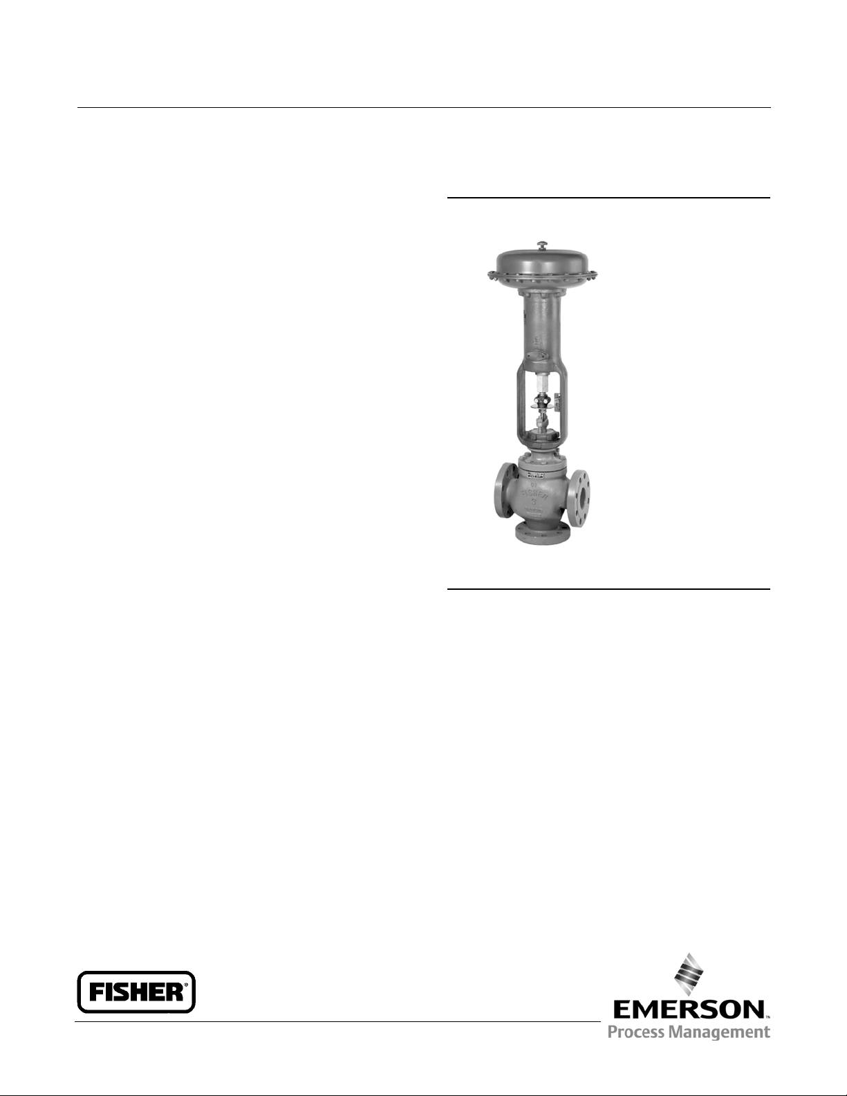
Figure 1. Fisher YD Valve with 667 Actuator
W2081
Introduction
Scope of Manual
This instruction manual includes installation, maintenance, and parts information for NPS 1/2 through 8 YD and NPS
1/2 through 6 YS control valves. Refer to separate manuals for instructions covering the actuators and accessories.
Do not install, operate, or maintain YD or YS valves without being fully trained and qualified in valve, actuator, and
accessory installation, operation, and maintenance. To avoid personal injury or property damage, it is important to
carefully read, understand, and follow all the contents of this manual, including all safety cautions and warnings. If you
have any questions about these instructions, contact your Emerson Process Management sales office before
proceeding.
www.Fisher.com
Page 2

YD and YS Valves
October 2014
Table 1. Specifications
Instruction Manual
D100425X012
Valve Sizes, Ratings, and End Connections
(1,2)
Cast Iron Valves
Flanged: NPS 1-1/2 through 6 CL125 flat-face or
CL250 raised-face flanges per ASME B16.1
Screwed: NPS 1-1/2 and 2 consistent with ASME B16.4
Steel and Stainless Steel Valves
Flanged: NPS 1 through 8 CL150, 300, and 600
raised-face or ring-type joint flanges per ASME B16.5
Screwed or Socket Welding: NPS 1/2 through 2
consistent with ASME B16.11
Buttwelding: NPS 1 through 8. All available
ASME B16.25 schedules that are consistent with
ASME B16.34
Also see table 2
Do not exceed the pressure, temperature, and
pressure drop conditions specified when the valve
was ordered. See the Installation section for
additional information.
Shutoff Classifications per ANSI/FCI 70-2
and IEC 60534-4
YD
Standard Design: Class IV
High-Temperature Design: Class II
YS
Standard Class: Class IV
Optional Class: Class V
Flow Characteristic
Linear
Maximum Inlet Pressure
(1)
Approximate Shipping Weights
Cast Iron Valves
Flanged: Consistent with CL125B or 250B per ASME
B16.1
Screwed: Consistent with CL250 per ASME B16.4
WCC and Stainless Steel Valves
Flanged: Consistent with CL150, 300, and 600
(3)
per
ASME B16.34
Screwed or Welding: Consistent with flanged CL600
per ASME B16.34
1. EN (or other) ratingsand end connections can usually be supplied; consult your Emerson Process Management sales office.
2. The pressureor temperature limits in this manual, andany applicable standard limitations, should not be exceeded.
3. Certain bonnet bolting material selections may require a CL600 easy-e valve assembly to be d erated. Contact your Emerson Process Management sales office.
NPS 1/2, 3/4 Valves: 14 kg (30 pounds)
NPS 1 Valves: 18 kg (40 pounds)
NPS 1-1/2 Valves: 27 kg (60 pounds)
NPS 2 Valves: 39 kg (85 pounds)
NPS 2-1/2 Valves: 50 kg (110 pounds)
NPS 3 Valves: 68 kg (150 pounds)
NPS 4 Valves: 109 kg (240 pounds)
NPS 6 Valves: 227 kg (500 pounds)
NPS 8 Valves: 447 kg (985 pounds)
Description
The YD and YS valves are three-way valves for throttling or on-off (flow switching) service with converging (flow
mixing) or diverging (flow splitting) flow patterns. YS valves, when used in diverging service, are recommended for
on-off applications only. These valves are generally shipped as part of a control valve assembly, having a diaphragm,
piston, or manual actuator mounted on them. A typical construction is shown in figure 1.
Specifications
Specifications for the YD and YS valves are shown in table 1. Some specifications appear on the actuator nameplate if
the valve is part of a complete control valve assembly.
Educational Services
For information on available courses for Fisher YD and YS valves, as well as a variety of other products, contact:
Emerson Process Management
Educational Services - Registration
Phone: 1-641-754-3771 or 1-800-338-8158
E-mail: education@emerson.com
http://www.emersonprocess.com/education
2
Page 3

Instruction Manual
D100425X012
YD and YS Valves
October 2014
Installation
WARNING
Always wear protective gloves, clothing, and eyewear when performing any maintenance operations to avoid personal
injury.
Personal injury or equipment damage caused by sudden release of pressure might result if the valve assembly is installed
where service conditions could exceed the limits given in table 1 or on the appropriate nameplates. To avoid such injury or
damage, provide a relief valve for overpressure protection as required by government or accepted industry codes and good
engineering practices.
Check with your process or safety engineer for any additional measures that must be taken to protect against process
media.
If installing into an existing application, also refer to the WARNING at the beginning of the Maintenance section in this
instruction manual.
CAUTION
When ordered, the valve configuration and construction materials were selected to meet particular pressure, temperature,
pressure drop, and controlled fluid conditions. Responsibility for the safety of process media and compatibility of valve
materials with process media rests solely with the purchaser and end-user. Since some body/trim material combinations
are limited in their pressure drop and temperature ranges, do not apply any other conditions to the valve without first
contacting your Emerson Process Management sales office.
Before installing the valve, inspect the valve and pipelines for any damage and any foreign material which may cause
product damage.
1. Before installing the valve, inspect it for any shipping damage and for any foreign material in the valve body cavity.
2. Clean out all pipelines to remove pipe scale, chips, welding slag, and other foreign materials.
3. Use accepted piping and welding practices when installing the valve. For flanged valves, use suitable gaskets
between the valve and the pipeline flanges.
4. Do not install the valve in a system where the working pressures exceed those specified in the ASME
pressure/temperature ratings or those specified by Emerson Process Management.
5. If continuous operation is required during maintenance and inspection, install a conventional three-valve bypass
around the valve so that the valve can be isolated.
6. Orient the valve so that flow will be in the direction indicated by the flow arrows.
Note
The common port for the YD is the bottom port as shown on the flow direction plates (key 17) in figure 10. The common port for
the YS is the left-hand port as shown on the flow direction plates in figure 9.
CAUTION
Depending on valve body materials used, post weld heat treating may be required. If so, damage to internal elastomeric
and plastic parts, as well as internal metal parts is possible. Threaded connections may also loosen. In general, if post weld
3
Page 4

YD and YS Valves
October 2014
heat treating is to be performed, all trim parts should be removed. Contact your Emerson Process Management sales office
for additional information.
Instruction Manual
D100425X012
7. YD or YS control valves can be installed in any position, although the recommended position is with the actuator
vertical above the valve. For NPS 4 and 6 YS valves, size 80 or larger actuators mounted between 45 degrees above
and 45 degrees below horizontal should be supported. If forces other than normal gravitational forces are
experienced, such as vibrational forces, smaller size actuators might also need to be supported when they are not in
a vertical position. For further information, consult your Emerson Process Management sales office.
Table 2. Valve Body Sizes and End Connections
VALVES SIZE, NPS CAST IRON VALVES STEEL OR STAINLESS STEEL VALVES
1/2, 3/4 --- NPT screwedor socket weld
1 ---
1-1/2, 2 NPT screwed; CL125 flat-face flanged; or CL250 raised-face flanged
2-1/2, 3, 4, 6 CL125 flat-face or CL250 raised-faceflanged
8 ---
NPT screwed;CL150, 300, or 600 raised-faceor ring-type
joint flanged; buttwelding; or socket weld
NPT screwed;CL150, 300, or 600 raised-faceor ring-type
joint flanged; buttwelding; or socket weld
CL150, 300, or 600 raised face or ring-type jointflanged;
or buttwelding
CL150, 300, or 600 raised face, ring-typejoint, or
buttwelding
WARNING
Personal injury could result from packing leakage. Valve packing was tightened before shipment; however, the packing
might require some readjustment to meet specific service conditions. Check with your process or safety engineer for any
additional measures that must be taken to protect against process media.
Valves with ENVIRO-SEAL live-loaded packing or HIGH-SEAL live-loaded packing will not require this initial
re-adjustment. See the Fisher instruction manuals titled ENVIRO-SEAL Packing System for Sliding-Stem Valves or
HIGH-SEAL Live-Loaded Packing System (as appropriate) for packing instructions. If you wish to convert your present
packing arrangement to ENVIRO-SEAL packing, refer to the retrofit kits listed in the parts kit subsection near the end of
this manual.
Maintenance
Valve parts are subject to normal wear and must be inspected and replaced as necessary. Inspection and maintenance
frequency depends on the severity of service conditions. This section includes instructions for trim maintenance,
packing maintenance, and ENVIRO-SEAL bellows seal bonnet replacement. All maintenance operations may be
performed with the valve in the line.
WARNING
Avoid personal injury or property damage from sudden release of process pressure or uncontrolled movement of parts.
Before performing any maintenance operations:
D Do not remove the actuator from the valve while the valve is still pressurized.
D Always wear protective gloves, clothing, and eyewear when performing any maintenance operations to avoid personal
injury.
D Disconnect any operating lines providing air pressure, electric power, or a control signal to the actuator. Be sure the
actuator cannot suddenly open or close the valve.
4
Page 5
Instruction Manual
D100425X012
D Use bypass valves or completely shut off the process to isolate the valve from process pressure. Relieve process pressure
from both sides of the valve. Drain the process media from both sides of the valve.
D Vent the power actuator loading pressure and relieve any actuator spring precompression.
D Use lock-out procedures to be sure that the above measures stay in effect while you work on the equipment.
D The valve packing box may contain process fluids that are pressurized, even when the valve has been removed from the
pipeline. Process fluids may spray out under pressure when removing the packing hardware or packing rings, or when
loosening the packing box pipe plug.
D Check with your process or safety engineer for any additional measures that must be taken to protect against process
media.
YD and YS Valves
October 2014
CAUTION
Follow instructions carefully to avoid damaging the product surfaces, which could result in damage to the product.
Packing Lubrication
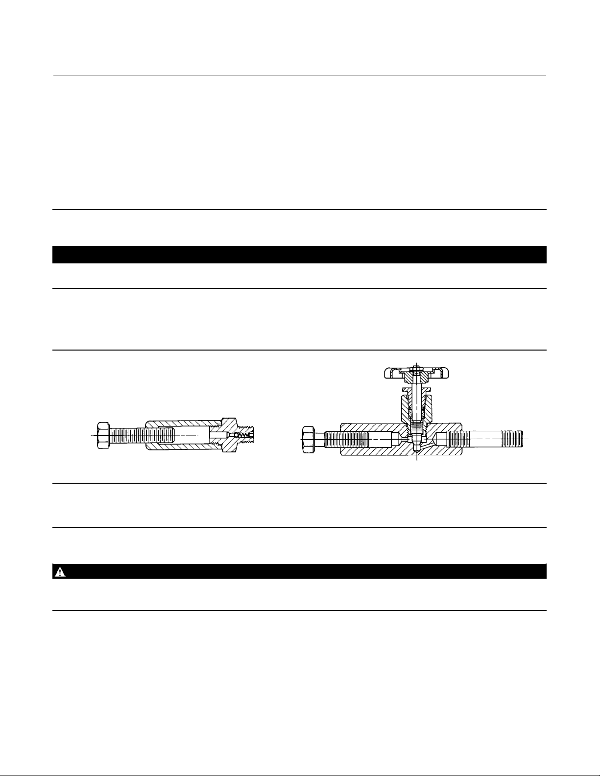
Figure 2. Lubricator and Lubricator/Isolating Valve (Optional)
10A9421-A
AJ5428-D
A0832-2
Note
ENVIRO-SEAL and HIGH-SEAL packing do not require lubrication.
LUBRICATOR
LUBRICATOR/ISOLATING VALVE
WARNING
To avoid personal injury or property damage resulting from fire or explosion, do not lubricate packing used in oxygen
service or in processes with temperatures over 260_C (500_F).
If a lubricator or lubricator/isolating valve (figure 2) is provided for PTFE/composition or other packings that require
lubrication, it will be installed in place of the pipe plug (key 14, figure 13). Use a good quality silicon-base lubricant. Do
not lubricate packing used in oxygen service or in processes with temperatures over 260_C(500_F). To operate the
lubricator, simply turn the cap screw clockwise to force the lubricant into the packing box. The lubricator/isolating
valve operates the same way except open the isolating valve before turning the cap screw and then close the isolating
valve after lubrication is completed.
5
Page 6
YD and YS Valves
October 2014
Instruction Manual
D100425X012
Packing Maintenance
Note
For valves with ENVIRO-SEAL packing, see the Fisher instruction manual ENVIRO-SEAL Packing System for Sliding-Stem Valves for
packing instructions.
For valves with HIGH-SEAL packing, see the Fisher instruction manual HIGH-SEAL Live-Loaded Packing System for packing
instructions.
Packing Replacement
WARNING
Observe the warning at the start of the Maintenance section.
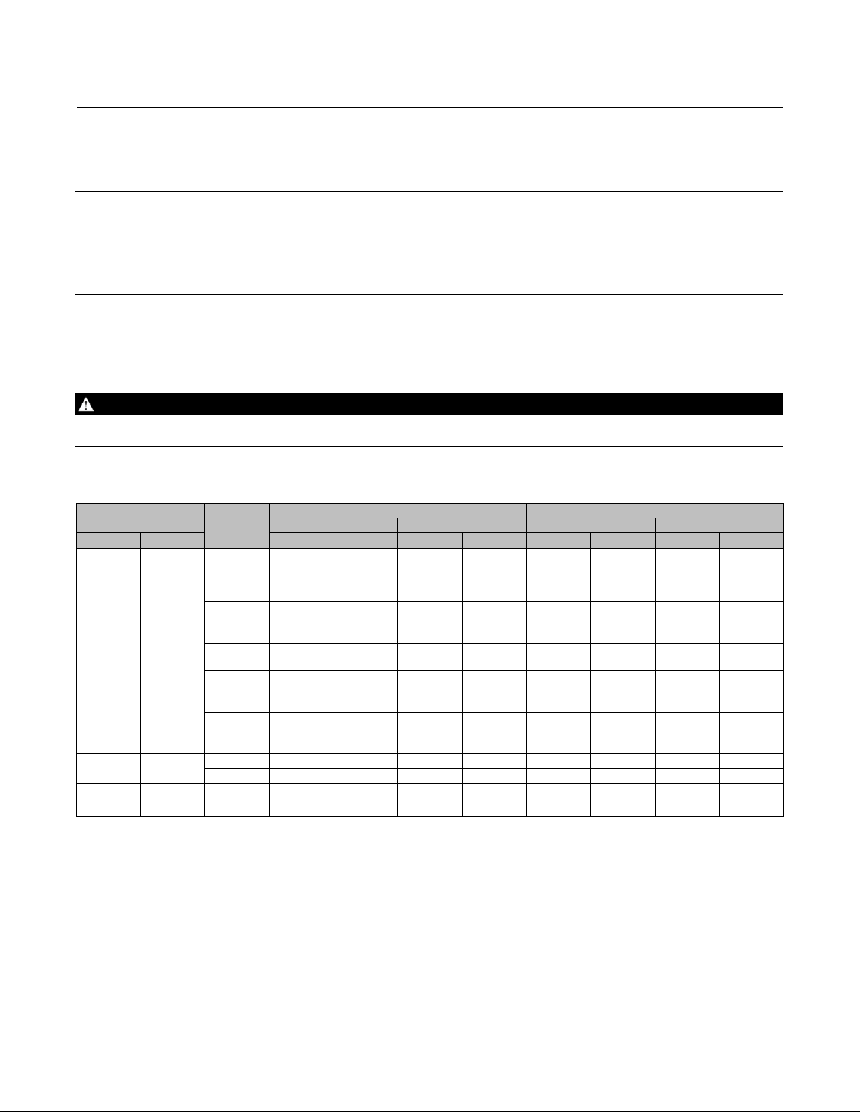
Table 3. Recommended Torque for Packing Flange Nuts
VALVE STEM
DIAMETER
mm Inches NSm LbfSin NSm LbfSin NSm LbfSin NSm LbfSin
9.5 3/8
12.7 1/2
19.1 3/4
25.4 1
31.8 1-1/4
PRESSURE
RATING
CL125,
150
CL250,
300
CL600 6 49 8 73 3 23 4 35
CL125,
150
CL250,
300
CL600 9 81 14 122 4 39 7 58
CL125,
150
CL250,
300
CL600 21 182 31 274 10 87 15 131
CL300 26 226 38 339 12 108 18 162
CL600 35 310 53 466 17 149 25 223
CL300 36 318 54 477 17 152 26 228
CL600 49 437 74 655 24 209 36 314
Minimum Torque Maximum Torque Minimum Torque Maximum Torque
3 27 5 40 1 13 2 19
4 36 6 53 2 17 3 26
5 44 8 66 2 21 4 31
7 59 10 88 3 28 5 42
11 99 17 149 5 47 8 70
15 133 23 199 7 64 11 95
GRAPHITE TYPE PACKING PTFE TYPE PACKING
The following procedure covers PTFE V-ring packing. A similar procedure can be followed for PTFE/composition
packing. However, because PTFE/composition packing comes in split rings, it is possible to replace the rings without
removing the actuator from the valve.
Installation of graphite ribbon/filament packing requires special care to avoid trapping air between the rings. Start only
oneringatatimewithoutforcingthetopofthepackingringbelowthebottomoftheentrancechamferofthe
packing box. Thus, when a ring is added, the stack should not be pushed into the cavity more than the thickness of the
added ring.
The arrangement of packing box parts is shown in figures 3, 4, 5, 6, and 7. Key numbers used in the following steps are
showninfigures13and14.
6
Page 7

Instruction Manual
D100425X012
1. Remove the actuator and bonnet according to steps 1 through 4 of the Disassembly procedure in the Maintenance
sectiononpage7.
2. With the stem and valve plug assembly removed from the bonnet, remove the packing nuts (key 5), packing flange
(key 3), wiper ring (key 12), and packing follower (key 13) from the bonnet. The old packing can then be pulled out
with a packing hook (take care to avoid scratching the packing box wall) or pushed out using a rod inserted through
the bottom of the bonnet.
3. Clean the packing box and all metal parts.
4. Complete maintenance necessary on other parts and install the bonnet on the valve as indicated in the Assembly
section (starting on page 12).
5. Install the new packing and associated parts in the sequence shown in figures 3, 4, 5, 6, and 7. Be careful not to
damage the packing during installation.
6. Replace the packing flange and packing flange nuts.
For spring-loaded PTFE V-ring packing, tighten the packing flange nuts until the shoulder on the packing follower
contacts the bonnet.
For graphite packing, tighten the packing flange nuts to the maximum recommended torque shown in table 3. Then,
loosen the packing flange nuts, and retighten them to the recommended minimumtorqueshownintable3.
For other packing types, tighten the packing flange nuts alternately in small equal increments until one of the nuts
reaches the minimum recommended torque shown in table 3. Then, tighten the remaining flange nut until the
packing flange is level and at a 90-degree angle to the valve stem.
YD and YS Valves
October 2014
For ENVIRO-SEAL or HIGH-SEAL live-loaded packing, refer to the note at the beginning of the Packing Maintenance
section.
7. Mount the actuator on the bonnet and make up the stem connection according to the procedure given in the
appropriate actuator instruction manual.
Trim Maintenance
WARNING
Observe the warning at the start of the Maintenance section.
CAUTION
To avoid damaging parts, do not grip the bellows shroud or other parts of the stem/bellows assembly. Grip only the flat
areas on the stem where it extends out of the top of the bellows shroud.
Key numbers in the following procedures are shown in figure 10 for standard YD, in figure 11 for high-temperature YD,
and in figure 9 for YS, except where indicated.
Disassembly
1. Isolatethecontrolvalvefromthelinepressure,releasepressure from both sides of the valve, and drain the process
mediafrombothsidesofthevalve.Removeactuatorsupplypressure,anduselock-outprocedurestobesurethat
the above measures stay in effect while you work on the equipment.
7
Page 8
YD and YS Valves
October 2014
Instruction Manual
D100425X012
WARNING
See the WARNING at the beginning of the Maintenance section for more information.
2. Disconnect the actuator stem connector and remove the locknut (key 15, figure 13) that holds the actuator to the
valve. (Valves with a 127 mm (5-inch) yoke boss use cap screws and nuts to secure the actuator on the valve). Then
lift the actuator from the valve.
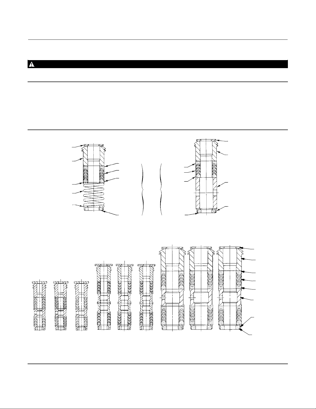
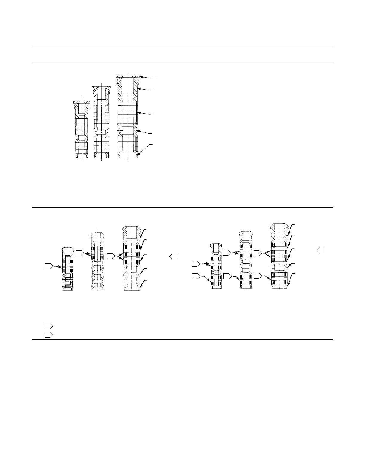
Figure 3. Fisher PTFE V-Ring Packing Arrangements
UPPER WIPER
(KEY 12)
PACKING
FOLLOWER
(KEY 13)
WASHER
(KEY 10)
SPRING
(KEY 8)
PACKING BOX
RING (KEY 11)
12A7837-A
B1429-2
FOR 316 OR 17-4PH SST
METAL PACKING BOX PARTS
FEMALE
ADAPTOR
PACKING
RING
MALE
ADAPTOR
LOWER
WIPER
PACKING
SET
(KEY 6)
SINGLE ARRANGEMENT
FEMALE
ADAPTOR
PACKING
RING
MALE
ADAPTOR
LOWER
WIPER
FORALLOTHERMETALPACKING
BOX PART MATERIALS
UPPER WIPER
(KEY 12)
PACKING
FOLLOWER (KEY 13)
SPACER (KEY 8)
PACKING BOX
RING (KEY 11)
12A8187-C 12A7814-C 12A7839-A
ASSEMBLY 1
(POSITIVE
PRESSURES)
ASSEMBLY 2
(VACUUM)
ASSEMBLY 3
(POSITIVE
PRESSURES
& VACUUM)
ASSEMBLY 1
(POSITIVE
PRESSURES)
ASSEMBLY 2
(VACUUM)
ASSEMBLY 3
(POSITIVE
PRESSURES
& VACUUM)
ASSEMBLY 1
(POSITIVE
PRESSURES)
ASSEMBLY 2
9.5 mm (3/8 INCH) STEM 12.7 mm (1/2 INCH)STEM 19.1,25.4, OR 31.8 mm
(3/4,1,OR1-1/4INCH)STEM
B1428-2
DOUBLE ARRANGEMENTS
8
(VACUUM)
ASSEMBLY 3
(POSITIVE
PRESSURES
& VACUUM)
UPPER WIPER
(KEY 12)
PACKING
FOLLOWER (KEY 13)
MALE ADAPTOR
PACKING RING
FEMALE ADAPTOR
LANTERN RING
(KEY 8)
PACKING BOX
RING (KEY 11)
LOWER WIPER
Page 9
Instruction Manual
D100425X012
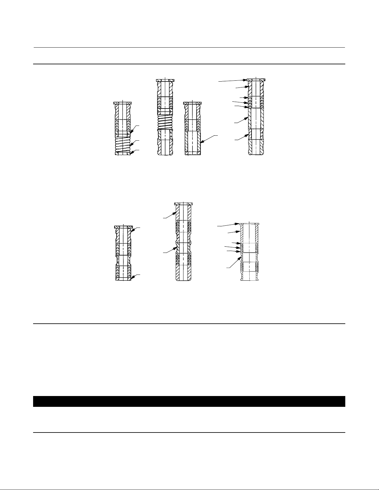
Figure 4. Detail of Fisher PTFE/Composition Packing Arrangements
UPPER WIPER
(KEY 12)
PACKING
FOLLOWER (KEY 13)
PACKING RING
(KEY 7)
LANTERN RING
(KEY 8)
PACKING BOX
RING (KEY 11)
YD and YS Valves
October 2014
12A8188-A
12A7815-A
12A8173-A
A2619-1
9.5 mm
(3/8 INCH)
STEM
12.7 mm
(1/2 INCH)
STEM
19.1, 25.4, OR 31.8 mm
(3/4,1,OR1-1/4INCH)
STEM
TYPICAL (DOUBLE) ARRANGEMENTS
Figure 5. Fisher Graphite Ribbon/Filament Packing Arrangements
PACKING
FOLLOWER
GRAPHITE
RIBBON
1
1
14A3411-A
9.5 mm
(3/8-INCH)
13A9775-B
12.7 mm
(1/2-INCH)
STEM
A2438-2
1
2
SINGLE PACKING ARRANGEMENT DOUBLE PACKING ARRANGEMENT
NOTE:
0.102 mm (0.004 INCH) THICK SACRIFICIAL ZINC WASHERS.
USE ONLY ONE BELOW EACH GRAPHITE RIBBON RING.
HAS THE APPEARANCE OF A WOVEN OR BRAIDEDRING.
1
13A9776-B
19.1 OR 25.4 mm
(3/4 OR1-INCH)
STEM
STEM
PACKING RING
GRAPHITE
FILAMENT
PACKING RING
LANTERN RING
PACKING BOX
RING
2
1
1
14A2153-B
(3/8-INCH)
9.5 mm
STEM
1
1
14A1849-B
12.7 mm
(1/2-INCH)
STEM
1
1
14A1780-B
19.1 OR 25.4 mm
(3/4 OR 1-INCH)
STEM
PACKING
FOLLOWER
GRAPHITE
RIBBON
PACKING RING
GRAPHITE
FILAMENT
PACKING RING
LANTERN RING
PACKING BOX
RING
2
9
Page 10
YD and YS Valves
October 2014
Figure 6. PTFE Packing Arrangements for Use in Fisher ENVIRO-SEAL Bellows Seal Bonnets
UPPER WIPER
(KEY 12)
BUSHING (KEY 13)
PACKING SET: (KEY 6)
FEMALE ADAPTOR
PACKING RING
MALE ADAPTOR
SPACER
THRUST
RING
(KEY 39)
SPRING
(KEY 8)
THRUST
12B4182-A SHT 1 12B4185-A SHT 1 12B4182-A SHT 2
9.5 mm
(3/8 INCH)
STEM
RING
(KEY 39)
(1/2 INCH)
12.7 mm
STEM
9.5 mm
(3/8 INCH)
STEM
FOR S31600 (316 SST)
PACKING BOX PARTS
SINGLE ARRANGEMENTS
BUSHING
(KEY 13)
BUSHING
(KEY 13)
SPACER
(KEY 8)
UPPER WIPER
BUSHING (KEY 13)
PACKING SET: (KEY 6)
FEMALE ADAPTOR
PACKING RING
MALE ADAPTOR
MATERIALS EXCEPT S31600
(KEY 12)
(KEY 8)
SPACER
(KEY 8)
12B4185-A SHT 2
12.7 mm
(1/2 INCH)
FOR ALL PACKING BOX
STEM
Instruction Manual
D100425X012
SPACER
(KEY 8)
THRUST
12B4183-A 18 A0906-D 18A5338-A
9.5 mm
(3/8 INCH)
STEM
A5863
RING
(KEY 39)
12.7 mm
(1/2 INCH)
STEM FOR
NPS 2 VALVES
DOUBLE ARRANGEMENTS
12.7 mm
(1/2 INCH)
STEM FOR
NPS 3 AND 4 VALVES
3. Removethenuts(key16,figures9and10)orcapscrewsfromthebonnetflange.
4. Lift off the bonnet along with the valve plug and stem (keys 2 and 5, figures 9 and 10). Due to the design of the
valve, several other trim parts will be drawn out with the valve plug. They are as follows:
YD (Standard)--The upper cage (key 3A) and associated seals, gaskets, and shim (keys 9, 11, 19, 20A, 20B, and 22).
YD (High Temperature)--The upper cage (key 3B) and associated gaskets and shim (keys 9, 11, and 22).
YS--The upper seat (key 7), upper cage (key 3), and associated gaskets and shim (keys 9, 11, and 22).
CAUTION
The exposed portion of the cage provides a guiding surface that must not be damaged during disassembly or maintenance.
Damage could affect valve performance. If the cage is stuck in the valve, use a rubber mallet to strike the exposed portion
at several points around the circumference.
10
Page 11

Instruction Manual
D100425X012
YD and YS Valves
October 2014
Figure 7. Double Graphite Ribbon/Filament Arrangements for Use in Fisher ENVIRO-SEAL Bellows Seal Bonnets
BUSHING(KEY13)
1
GRAPHITE FILAMENT PACKING RING (KEY 7)
GRAPHITE RIBBON PACKING RING (KEY 7)
SPACER (KEY 8)
A5870
1
1
1
12B4181-A
9.5 mm
(3/8-INCH)
STEM
NOTE:
1
0.102 mm (0.004 INCH) THICK SACRIFICIAL ZINC WASHERS;
USE ONLY ONE BELOW EACH GRAPHITE RIBBON RING.
18A0909-D
12.7 mm
(1/2-INCH)
STEM FOR
NPS 2 VALVES
1
1
12B6102-A
12.7 mm
(1/2-INCH)
STEM FOR
NPS 3 AND 4 VALVES
Take proper care not to damage any sealing or seating surfaces as nicks or scratches in these parts might cause
leakage.
5. Loosen the packing flange nuts (key 5, figures 13 and 14) and draw the valve plug and stem straight out the bottom
of the bonnet. Lift all cage and seat parts off the valve plug and stem. If the stem for YD or YS requires replacing,
drivethepin(key6)outandunscrewthestemfromtheplug.
Table 4. Pin Drill Sizes
VALVE TYPE VALVE STEM CONNECTION, mm (INCH) DRILL SIZE, INCHES
YD & YS
9.5 (3/8)
12.7 (1/2)
19.1 (3/4)
25.4 (1)
3/32
1/8
3/16
1/4
Table 5. Recommended Bolt Torques for B7 Body-to-Bonnet Bolting
VALVE SIZE,
NPS
1/2, 3/4
1, 1-1/2
2
2-1/2
3
4
6
(2)
8
1. For other materials, contact your Emerson Process Management sales office.
2. For NPS 8 YD valves, the bottom adaptor has shorter bolts than the bonnet, but the bolt torque is the same as the bonnet torque.
(1)
RECOMMENDED BOLT
TORQUE, NSm(LbfSft)
129 (95)
129 (95)
96 (71)
96 (71)
169 (125)
271 (200)
549 (405)
CL150/300: 373 (275)
CL600: 522 (385)
6. To replace the adaptor (key 24, figure 15) on ENVIRO-SEAL bellows seal bonnets, place the plug stem assembly and
valve plug in a soft-jaw chuck or other type of vise so that the jaws grip a portion of the valve plug that is not a
seating surface. Drive out the pin (key 36, figure 15). Reverse the plug stem assembly in the soft-jaw chuck or vise.
Grip the flat areas on the valve stem just below the threads for the actuator/stem connection. Unscrew the valve
plug/adaptor assembly (key 24, figure 15) from the valve stem assembly (key 20, figure 15).
11
Page 12

YD and YS Valves
October 2014
Instruction Manual
D100425X012
CAUTION
Never use an old stem with a new valve plug. The use of an old stem requires drilling a new pin hole through the stem (or
adaptor, in case an ENVIRO-SEAL bellows seal bonnet is being used). This drilling weakens the stem or adaptor and may
cause failure in service. However, a used valve plug may be reused with a new stem or adaptor.
7. The internal parts of the bonnet can now be disassembled, if necessary. For packing replacement, refer to the
section entitled Packing Replacement on page 6.
8. Standard YD Only–It is recommended that the cage seal (key 19), seal ring (key 20A), and backup ring (key 20B) be
replaced upon assembly. These can be removed by prying them out of the upper cage grooves with a screwdriver or
a soft-tipped instrument. If a screwdriver is used, take care not to scratch the surfaces of the cage.
9. The remaining trim parts can now be lifted out of the valve. Under severe service conditions, some of these parts
mighthavebecomestucktothevalve.Inthiscase,itmightbenecessarytouseaseatringpullertoremovethese
parts. Because there is a slight clearance around the outer circumference of the lower cage (key 4) and seat ring
(key 8), it might be possible to remove these by tapping them loose, if interior room permits.
Assembly
YD (Standard)
1. Use new gaskets, seals, and s him (keys 9, 11, 14, 19, 20A, 20B, and 22) o n assembly and wipe all sealing surfaces
with a clean cloth.
2. For NPS 8 YD, install the bottom flange adaptor (key 24) and gasket (key 9).
3. Install the seat ring gasket (key 14) and place the seat ring (key 8) on top of the gasket.
4. Install the lower cage (key 4) into the valve, being certain that it fits down over the raised portion of the seat ring.
Thenarrowportionofthecagewindowsshouldpointdownward.
5. Slip the O-ring cage seal (key 19) over the bottom of the upper cage (key 3A) and into the cage groove.
Figure 8. Typical Bolting Pattern
A0274-1
6. Press the backup ring (key 20B) and the seal ring (key 20A), respectively, into the inner groove of the upper cage. It
might be necessary to bend one side of each of these in slightly to accomplish this. Take care not to distort the rings
when doing this.
7. If a new stem (key 5) is to be used, screw the stem into the valve plug (key 2) until it wedges tight at the end of the
valve stem thread.
12
Page 13

Instruction Manual
D100425X012
YD and YS Valves
October 2014
CAUTION
Never use an old stem with a new valve plug. The use of an old stem requires drilling a new pin hole through the stem (or
adaptor, in case an ENVIRO-SEAL bellows seal bonnet is being used). This drilling weakens the stem or adaptor and may
cause failure in service. However, a used valve plug may be reused with a new stem or adaptor.
Locate the pilot hole in the valve plug and drill the hole through the plug and stem assembly (determine drill size from
table4).Driveinthepintolocktheassembly.
8. For ENVIRO-SEAL bellows seal bonnets, grip the flats of the stem extending out of the top of the bellows shroud
with a soft-jaw chuck or other type of vise. Screw the valve plug/adaptor assembly onto the valve stem. Tighten as
necessarytoalignthepinholeinthestemwithoneoftheholesintheadaptor.Securetheadaptortothestemwith
anewpin.
CAUTION
To prevent possible damage to the seal ring and cage seal, exercise care in the following procedure.
9. Placetheuppercage(key3A)overtheplugassembly,beingcertainnottodamagethesealring,andlowerthis
entire assembly into the valve. Due to the close fit between the valve body bore and the cage seal, it will be
necessary to apply a steady force to the top of the cage for final positioning inside the valve body bore. Take care to
ensurethattheuppercageslipsintothelowercageandthecagesealisnotdamaged.
10. Place the spiral wound gasket (key 11), shim (key 22), and bonnet gasket (key 9), respectively, over the upper
cage.
11. Mount the bonnet onto the valve with the lubricator or pipe plug parallel with the pipeline.
Note
Stud(s) and nut(s) should be installed such that the manufacturer's trademark and material grade marking is visible, allowing easy
comparison to the materials selected and documented in the Emerson/Fisher serial card provided with this product.
WARNING
Personal injury or damage to equipment could occur if improper stud and nut materials or parts are used. Do not operate or
assemble this product with stud(s) and nut(s) that are not approved by Emerson/Fisher engineering and/or listed on the
serial card provided with this product. Use of unapproved materials and parts could lead to stresses exceeding the design
or code limits intended for this particular service. Install studs with the materialgrade and manufacturer's identification
mark visible. Contact your Emerson Process Management representative immediately if a discrepancy between actual
parts and approved parts is suspected.
13
Page 14

YD and YS Valves
October 2014
Instruction Manual
D100425X012
12. Lubricate the valve stud bolts or cap screws (key 15) and install the nuts (key 16) on the bolts using accepted
bolting practices. Tighten the nuts to the recommended bolt torques given in table 5. Follow a pattern similar to
that shown in figure 8.
Note
It might be necessary to repeat the bolting pattern several times until the bonnet-to-body seal is made, because the tightening of
one nut might loosen an adjacent nut. Repeat the pattern until none of the nuts will turn at the recommended torque.
13. Mount the actuator on the bonnet and make up the stem connection according to the procedure given in the
appropriate actuator instruction manual.
YD (High Temperature)
1. Use new gaskets, seals, and shim (keys 9, 11, 13, 14, 19, 20, and 22) on assembly and wipe all sealing surfaces with
acleancloth.
2. For NPS 8 YD, install the bottom flange adaptor (key 24) and gasket (key 9).
3. Install the seat ring gasket (key 14) and place the seat ring (key 8) on top of the gasket followed by the spiral wound
spring (key 13).
4. Install the lower cage (key 4) into the valve, being certain that it fits down over the raised portion of the seat ring.
Thenarrowportionofthecagewindowsshouldpointdownward.
5. Place one of the retaining ring gaskets (key 19) into the valve.
6. If a new stem (key 5) is to be used, screw the stem into the valve plug (key 2) until it wedges tight at the end of the
valve stem thread.
CAUTION
Never use an old stem with a new valve plug. The use of an old stem requires drilling a new pin hole through the stem (or
adaptor, in case an ENVIRO-SEAL bellows seal bonnet is being used). This drilling weakens the stem or adaptor and may
cause failure in service. However, a used valve plug may be reused with a new stem or adaptor.
Locate the pilot hole in the valve plug and drill the hole through the plug and stem assembly (determine drill size from
table4).Driveinthepintolocktheassembly.
7. For ENVIRO-SEAL bellows seal bonnets, grip the flats of the stem extending out of the top of the bellows shroud
with a soft-jaw chuck or other type of vise. Screw the valve plug/adaptor assembly onto the valve stem. Tighten as
necessarytoalignthepinholeinthestemwithoneoftheholesintheadaptor.Securetheadaptortothestemwith
anewpin.
8. Place the seal ring retainer (key 3C) into the valve and lower the valve plug assembly into the retainer orifice.
9. Carefully place the seal rings (key 20) over the valve plug, being certain that they rest against the retaining ring.
Each of these has a cut through its cross section. These cuts should be oriented 180 degrees apart to ensure a
proper seal.
10. Insert the other retaining ring gasket (key 19) on top of the retaining ring.
11. Lower the upper cage (key 3B) into the valve. When properly installed, the raised ring on the bottom of the cage
should fit snugly into the groove formed by the seal rings and the retaining ring.
12. Place the spiral wound gasket (key 11), shim (key 22), and bonnet gasket (key 9), respectively, over the upper
cage.
14
Page 15

Instruction Manual
D100425X012
YD and YS Valves
October 2014
13. Mount the bonnet onto the valve with the lubricator or pipe plug parallel with the pipeline.
Note
Stud(s) and nut(s) should be installed such that the manufacturer's trademark and material grade marking is visible, allowing easy
comparison to the materials selected and documented in the Emerson/Fisher serial card provided with this product.
WARNING
Personal injury or damage to equipment could occur if improper stud and nut materials or parts are used. Do not operate or
assemble this product with stud(s) and nut(s) that are not approved by Emerson/Fisher engineering and/or listed on the
serial card provided with this product. Use of unapproved materials and parts could lead to stresses exceeding the design
or code limits intended for this particular service. Install studs with the materialgrade and manufacturer's identification
mark visible. Contact your Emerson Process Management representative immediately if a discrepancy between actual
parts and approved parts is suspected.
14. Lubricate the valve stud bolts (key 15) and install the nuts (key 16) onto the bolts using good bolting practices.
Tighten the nuts to the recommended bolt torques given in table 5. A pattern similar to that shown in figure 8
should be followed.
Note
It might be necessary to repeat the bolting pattern several times until the bonnet-to-body seal is made, because the tightening of
one nut might loosen an adjacent nut. Repeat the pattern until none of the nuts will turn at the recommended torque.
15. Mount the actuator on the bonnet and make up the stem connection according to the procedure given in the
appropriate actuator instruction manual.
YS
1. Use new gaskets and shim (keys 9, 11, 12, 13, 14 and 22) on assembly and wipe all sealing surfaces with a clean
cloth.
2. Install the lower seat ring gasket (key 14) and place the lower seat ring (key 8) on top of the gasket followed by the
spiral wound spring (key 13).
3. Install the lower cage (key 4) into the valve, being certain that it fits down over the raised portion of the seat ring.
Thenarrowportionofthecagewindowsshouldpointdownward.
4. Place the upper seat ring gasket (key 12) into the valve.
5. If a new stem (key 5) is to be used, screw the stem into the valve plug (key 2) until it wedges tight at the end of the
valve stem thread.
CAUTION
Never use an old stem with a new valve plug. The use of an old stem requires drilling a new pin hole through the stem (or
adaptor, in case an ENVIRO-SEAL bellows seal bonnet is being used). This drilling weakens the stem or adaptor and may
cause failure in service. However, a used valve plug may be reused with a new stem or adaptor.
15
Page 16

YD and YS Valves
October 2014
Instruction Manual
D100425X012
Locate the pilot hole in the valve plug and drill the hole through the plug and stem assembly (determine drill size from
table4).Driveinthepintolocktheassembly.
6. For ENVIRO-SEAL bellows seal bonnets, grip the flats of the stem extending out of the top of the bellows shroud
with a soft-jaw chuck or other type of vise. Screw the valve plug/adaptor assembly onto the valve stem. Tighten as
necessarytoalignthepinholeinthestemwithoneoftheholesintheadaptor.Securetheadaptortothestemwith
anewpin.
7. Place the upper seat ring (key 7) and upper cage (key 3), respectively, over the plug and stem assembly, being
certain not to scratch any sealing surfaces. Lower this entire assembly into the valve.
8. Place the spiral wound gasket (key 11), shim (key 22), and bonnet gasket (key 9), respectively, over the upper cage.
9. Mount the bonnet onto the valve with the lubricator or pipe plug parallel with the pipeline.
Note
Stud(s) and nut(s) should be installed such that the manufacturer's trademark and material grade marking is visible, allowing easy
comparison to the materials selected and documented in the Emerson/Fisher serial card provided with this product.
WARNING
Personal injury or damage to equipment could occur if improper stud and nut materials or parts are used. Do not operate or
assemble this product with stud(s) and nut(s) that are not approved by Emerson/Fisher engineering and/or listed on the
serial card provided with this product. Use of unapproved materials and parts could lead to stresses exceeding the design
or code limits intended for this particular service. Install studs with the materialgrade and manufacturer's identification
mark visible. Contact your Emerson Process Management representative immediately if a discrepancy between actual
parts and approved parts is suspected.
10. Lubricate the valve stud bolts or cap screws (key 15) and install the nuts (key 16) onto the bolts using good bolting
practices. Tighten the nuts to the recommended bolt torques given in table 5. A pattern similar to that shown in
figure 8 should be followed.
Note
It might be necessary to repeat the bolting pattern several times until the bonnet-to-body seal is made, because the tightening of
one nut might loosen an adjacent nut. Repeat the pattern until none of the nuts will turn at the recommended torque.
11. Mount the actuator onto the bonnet and make up the stem connection according to the procedure given in the
appropriate actuator instruction manual.
ENVIRO-SEAL Bellows Seal Bonnet
Replacing a Plain or Extension Bonnet with an ENVIRO-SEAL Bellows Seal Bonnet
(Stem/Bellows Assembly)
1. Remove the actuator and bonnet according to steps 1 through 4 of the Disassembly procedure in the Maintenance
sectiononpage7.
2. With care, remove the valve plug and stem assembly from the valve. If necessary, also lift out the cage.
16
Page 17

Instruction Manual
D100425X012
YD and YS Valves
October 2014
CAUTION
To prevent possible product damage, cover the opening in the valve in the following procedure to protect the sealing
surfaces and to prevent foreign material from getting into the valve body cavity.
3. Remove and discard the existing bonnet gasket. Cover the valve body opening to protect sealing surfaces and to
prevent foreign material from entering the v alve body cavity.
Note
The ENVIRO-SEAL stem/bellows assembly for YD and YS valves is available only with a threaded and drilled plug/adaptor/stem
connection. The existing valve plug can be reused with the new s tem/bellows assembly or a new plug can be installed.
4. Inspect the existing valve plug. If the plug is in good condition, it can be reused with the new ENVIRO-SEAL
stem/bellows assembly. To remove the existing valve plug from the stem, first, place the existing plug stem
assembly and valve plug in a soft-jaw chuck or other type of vise so that the jaws grip a portion of the valve plug that
is not a seating surface. Drive out or drill out the pin (key 8).
5. Reversetheplugstemassemblyinthesoft-jawchuckorvise.Gripthevalvesteminanappropriateplaceand
unscrew the existing plug from the valve stem.
CAUTION
When installing a valve plug on the ENVIRO-SEAL stem/bellows assembly, the valve stem must not be rotated. Damage to
the bellows may result.
Do not grip the bellows shroud or other parts of the stem/bellows assembly. Grip only the flat areas on the stem where it
extends out of the top of the bellows shroud.
Note
The ENVIRO-SEAL stem/bellows assembly has a one-piece stem.
6. To attach the valve plug to the stem of the new ENVIRO-SEAL stem/bellows assembly, first attach the plug to the
adaptor (key 24). Locate the adaptor. Notice that a hole has not been drilled in the threads where the plug screws
onto the adaptor. Secure the valve plug in a soft-jaw chuck or other type of vise. Do not grip the plug on any seating
surface. Position the plug in the chuck or vise for easy threading of the adaptor. Thread the adaptor into the valve
plug and tighten to the appropriate torque value.
7. Select the proper size of drill bit and drill through the adaptor using the hole in the valve plug as a guide. Remove
any metal chips or burrs and drive in a new pin to lock the plug/adaptor assembly together.
8. Attach the plug/adaptor assembly to the ENVIRO-SEAL stem/bellows assembly by first securing the stem/bellows
assemblyinasoft-jawchuckorothertypeofvisesothatthejawsofthechuckorvisegriptheflatsofthestem
extendingoutofthetopofthebellowsshroud.Screwthevalveplug/adaptorassemblyontothevalvestem.
Tightenasnecessarytoalignthepinholeinthestemwithoneoftheholesintheadaptor.Securetheadaptortothe
stem with a new pin.
9. Inspect the seat ring (key 9) and soft seat parts (keys 21, 22, and 23); replace, if necessary.
10. Place a new gasket (key 10) into the valve in place of the bonnet gasket. Install the new stem/bellows assembly
with valve plug/adaptor by placing it into the valve on top of the new bellows gasket.
17
Page 18

YD and YS Valves
October 2014
Instruction Manual
D100425X012
11. Place a new gasket (key 22) over the stem/bellows assembly. Place the new ENVIRO-SEAL bonnet over the
stem/bellows assembly.
Note
Stud(s) and nut(s) should be installed such that the manufacturer's trademark and material grade marking is visible, allowing easy
comparison to the materials selected and documented in the Emerson/Fisher serial card provided with this product.
WARNING
Personal injury or damage to equipment could occur if improper stud and nut materials or parts are used. Do not operate or
assemble this product with stud(s) and nut(s) that are not approved by Emerson/Fisher engineering and/or listed on the
serial card provided with this product. Use of unapproved materials and parts could lead to stresses exceeding the design
or code limits intended for this particular service. Install studs with the materialgrade and manufacturer's identification
mark visible. Contact your Emerson Process Management representative immediately if a discrepancy between actual
parts and approved parts is suspected.
12. Properly lubricate the bonnet stud bolts. Install and tighten the bonnet hex nuts to the proper torque.
13. Install new packing and the metal packing box parts according to the appropriate arrangement in figure 17 or 18.
14. Install the packing flange. Properly lubricate the packing flange stud bolts and the faces of the packing flange nuts.
For graphite packing, tighten the packing flange nuts to the maximum recommended torque shown in table 6. Then,
loosen the packing flange nuts, and retighten them to the recommended minimumtorqueshownintable6.
For other packing types, tighten the packing flange nuts alternately in small equal increments until one of the nuts
reaches the minimum recommended torque shown in table 6. Then, tighten the remaining flange nut until the
packing flange is level and at a 90-degree angle to the valve stem.
15. Install travel indicator parts and stem locknuts; mount the actuator onto the valve according to the procedure in
the appropriate actuator instruction manual.
Replacement of an Installed ENVIRO-SEAL Bellows Seal Bonnet (Stem/Bellows Assembly)
1. Remove the actuator and bonnet according to steps 1 through 4 of the Disassembly procedure in the Maintenance
sectiononpage7.
CAUTION
To prevent possible product damage, cover the opening in the valve in the following procedure to protect the sealing
surfaces and to prevent foreign material from getting into the valve body cavity.
2. Carefully remove the ENVIRO-SEAL stem/bellows assembly. If necessary, also lift out the cage. Remove and discard
the existing bonnet gasket and bellows gasket. Cover the valve body opening to protect sealing surfaces and to
prevent foreign material from entering the v alve body cavity.
CAUTION
The ENVIRO-SEAL stem/bellows assembly for YD and YS valves is available only with a threaded and drilled
plug/adaptor/stem connection. The existing valve plug can be reused with the new stem/bellows assembly or a new plug
18
Page 19

Instruction Manual
D100425X012
can be installed. If the existing valve plug is reused, and the adaptor is in good condition, it may also be reused. However,
never reuse an old adaptor with a new valve plug. Using an old adaptor with a new valve plug requires drilling a new pin
hole in the adaptor. This drilling weakens the adaptor and may cause failure in service. However, a used valve plug may be
reused with a new adaptor.
YD and YS Valves
October 2014
3. Inspect the existing valve plug and adaptor. If they are in good condition, they can be reused with the new
stem/bellows assembly and they do not need to be separated.
CAUTION
When removing/installing a valve plug on the ENVIRO-SEAL stem/bellows assembly, the valve stem must not be rotated.
Damage to the bellows may result.
Do not grip the bellows shroud or other parts of the stem/bellows assembly. Grip only the flat areas on the stem where it
extends out of the top of the bellows shroud.
Note
The ENVIRO-SEAL stem/bellows assembly has a one-piece stem.
4. If the valve plug and adaptor are not in good condition and must be replaced, first remove the valve plug/adaptor
assemblyfromthestem/bellowsassembly;thenremovethevalveplugfromtheadaptor.First,placethe
stem/bellows assembly and valve plug in a soft-jaw chuck or other type of vise so that the jaws grip a portion of the
valveplugthatisnotaseatingsurface.Driveoutordrilloutthepin(key6,figure9,10,or11.Driveoutthepin(key
36, figure 15).
Table 6. Recommended Torque for Fisher ENVIRO-SEAL Bellows Seal Packing Flange Nuts
VALVE
SIZE,
1/2 - 2 1/2 3 24 5 48
VALVE STEM DIAMETER
NPS
3-4 1 7 60 10 84
THROUGH PACKING
MINIMUM TORQUE MAXIMUM TORQUE
NSm LbfSin NSm LbfSin
5. Reverse the stem/bellows and plug/adaptor assembly in the soft-jaw chuck or vise. Grip the flat areas on t he valve
stem just below the threads for the actuator/stem connection. Unscrew the plug/adaptor assembly from the
stem/bellows assembly. Unscrew the valve plug from the adaptor.
6. To attach either the existing valve plug or a new one to the stem of the new ENVIRO-SEAL stem/bellows assembly,
first attach the plug to the adaptor (if the valve plug was removed from the adaptor) as follows:
D Locate the adaptor. Notice that a hole has not been drilled in the threads where the plug screws onto the adaptor.
D Secure the valve plug in a soft-jaw chuck or other type of vise. Do not grip the plug on any seating surface. Position
the plug in the chuck or vise for easy threading of the adaptor.
D Thread the adaptor into the valve plug and tighten to the appropriate torque value.
7. Complete the installation by following steps 7 through 9 and steps 12 through 15 of the ENVIRO-SEAL Bellows Seal
Bonnet installation instructions given above.
Purging the ENVIRO -SEAL Bellows Seal Bonnet
The ENVIRO-SEAL bellows seal bonnet can be purged or leak tested. Refer to figure 15 for an illustration of an
ENVIRO-SEAL bellows seal bonnet, and perform the following steps for purging or leak testing.
19
Page 20

YD and YS Valves
October 2014
Instruction Manual
D100425X012
1. Remove the two diametrically opposed pipe plugs (key 16).
2. Connect a purging fluid to one of the pipe plug connections.
3. Install appropriate piping or tubing in the other pipe plug connection to pipe away the purging fluid or to make a
connection to an analyzer for leak testing.
Figure 9. Fisher YS Valve
COMMON PORT
30A3554-D
20
Page 21

Instruction Manual
D100425X012
Figure 10. Fisher YD Valve (Standard)
YD and YS Valves
October 2014
40A3552-F
Figure 11. Fisher YD Valve (High Temperature)
40A3552-F
COMMON PORT
21
Page 22

YD and YS Valves
October 2014
Figure 12. Fisher NPS 8 YD Valve
VIEW D
Instruction Manual
D100425X012
22
54B9114-A
COMMON PORT
Page 23

Instruction Manual
D100425X012
Figure 13. Fisher Standard Bonnet
AU3910-A
E1087
YD and YS Valves
October 2014
PLAIN BONNET
Figure 14. Fisher Extension Bonnet
CU3911-C
STYLE 1 OR 2
EXTENSION BONNET
Figure 15. Fisher ENVIRO-SEAL Bellows Seal Bonnet
j APPLY LUB
42B3947-A
ENVIRO-SEAL
BELLOWS SEAL BONNET
23
Page 24

YD and YS Valves
October 2014
Instruction Manual
D100425X012
Parts Ordering
Eachvalveisassignedaserialnumberwhichcanbefoundonthevalve.Thissamenumberalsoappearsonthe
actuator nameplate when the valve is shipped from the factory as part of a control valve assembly. Always refer to the
serial number when corresponding with your Emerson Process Management sales office about this equipment. When
ordering replacement parts, also state the complete eleven-character part number for each part required from the
following parts list.
WARNING
Use only genuine Fisher replacement parts. Components that are not supplied by Emerson Process Management should
not, under any circumstances, be used in any Fisher valve, because they may void your warranty, might adversely affect the
performance of the valve, and could cause personal injury and property damage.
Parts Kits
Standard Packing Repair Kits (Non Live-Loaded)
Stem Diameter, mm (Inches)
Yoke Boss Diameter, mm (Inches)
PTFE (Contains keys 6, 8, 10, 11, and 12) RPACKX00012 RPACKX00022 RPACKX00032 RPACKX00342
Double PTFE (Contains keys 6, 8, 11, and 12) RPACKX00042 RPACKX00052 RPACKX00062 RPACKX00362
PTFE/Composition (Contains keys 7, 8, 11, and 12) RPACKX00072 RPACKX00082 RPACKX00092 ---
Single Graphite Ribbon/Filament (Contains keys 7 [ribbon ring],
7 [filament ring], 8, and 11)
Single Graphite Ribbon/Filament (Contains keys 7 [ribbon ring],
7 [filament ring], and 11)
Single Graphite Ribbon/Filament (Contains keys 7 [ribbon ring],
7 [filament ring])
Double Graphite Ribbon/Filament (Contains keys 7 [ribbon ring],
7 [filament ring], 8, and 11)
9.5 (3/8)
54 (2-1/8)
RPACKX00102 RPACKX00112 RPACKX00122 ---
--- --- --- RPACKX00532
RPACKX00132 RPACKX00142 RPACKX00152 ---
RPACKX00162 RPACKX00172 RPACKX00182 ---
12.7 (1/2)
71 (2-13/16)
19.1 (3/4)
90 (3-9/16)
25.4 (1)
127 (5)
Packing Kits (ENVIRO-SEAL) Repair
PACKING
MATERIAL
Double PTFE (contains keys 214, 215, & 218) RPACKX00192 RPACKX00202 RPACKX00212 RPACKX00222
Graphite ULF (contains keys 207, 208, 209, 210, and 214) RPACKX00592 RPACKX00602 RPACKX00612 RPACKX00622
STEM DIAMETERAND YOKE BOSS DIAMETER, mm (INCH)
9.5 (3/8)
54 (2-1/8)
12.7 (1/2)
71 (2-13/16)
19.1 (3/4)
90 (3-9/16)
25.4 (1)
127 (5)
Packing Kits (ENVIRO-SEAL) Retrofit
PACKING
MATERIAL
Double PTFE (contains keys 200, 201, 211, 212, 214, 215, 217, and 218) RPACKXRT012 RPACKXRT022 RPACKXRT032 RPACKXRT042
Graphite ULF (contains keys 200, 201, 207, 208, 209, 210,
211, 212, 214, and 217)
STEM DIAMETER AND YOKE BOSS DIAMETER, mm (INCH)
9.5 (3/8)
54 (2-1/8)
RPACKXRT262 RPACKXRT272 RPACKXRT282 RPACKXRT292
12.7 (1/2)
71 (2-13/16)
19.1 (3/4)
90 (3-9/16)
25.4 (1)
127 (5)
24
Page 25

Instruction Manual
D100425X012
Gasket Kits
Gasket Kits
VALVE SIZE, NPS
NPS 1/2 to 1-1/2
NPS 2 to 2-1/2
NPS 3
NPS 4
NPS 6
Valve Size, NPS Key Number YD Part Number YS Part Number
1/2 through1-1/2
2 through 2-1/2
3
4
6
YD and YS Valves
October 2014
(Includes keys 9, 11, 14, and 22)
Set RGASKETXB62 RGASKETXC22
9 1R2859X0042 1R2859X0042
11 1R286099442 1R286099442
12 --- 10A3326X052
13 --- 10A3325X062
14 10A3327X052 10A3327X052
22 16A1936X012 16A1936X012
Set RGASKETXB72 RGASKETXC32
9 1R3299X0042 1R3299X0042
11 1R329799442 1R329799442
12 --- 10A3384X042
13 --- 10A3383X042
14 10A3385X042 10A3385X042
22 16A1938X012 16A1938X012
Set RGASKETXB82 RGASKETXC42
9 1R3484X0042 1R3484X0042
11 1R348299442 1R348299442
12 --- 10A3437X062
13 --- 10A3436X042
14 10A3438X062 10A3438X062
22 16A1940X012 16A1940X012
Set RGASKETXB92 RGASKETXC52
9 1R3724X0042 1R3724X0042
11 1R372299442 1R372299442
12 --- 10A3479X052
13 --- 10A3478X052
14 10A3480X052 10A3480X052
22 16A1941X012 16A1941X012
Set RGASKETXC12 RGASKETXC62
9 1U5081X0052 1U5081X0052
11 1U508599442 1U508599442
12 --- 10A3525X042
13 --- 10A3524X022
14 11A9521X052 11A9521X052
22 16A1942X012 16A1942X012
YD
(Includes keys 9, 11, 12, 13, 14, and 22)
Part Number Part Number
RGASKETXB62
RGASKETXB72
RGASKETXB82
RGASKETXB92
RGASKETXC12
YS
RGASKETXC22
RGASKETXC32
RGASKETXC42
RGASKETXC52
RGASKETXC62
25
Page 26

YD and YS Valves
October 2014
Instruction Manual
D100425X012
Figure 16. Typical Fisher HIGH-SEAL Graphite ULF
Packing System
1. FIND NUMBER 219 NOT REQUIRED WITH 3/8 INCH STEM
39B4153-A
Figure 18. Typical Fisher ENVIRO-SEAL Packing
System with Graphite ULF Packing
STUD
(KEY 200)
HEX NUT
(KEY 212)
PACKING
FLANGE
(KEY 201)
PACKING
RING
(KEY 209)
PACKING
RING
(KEY 210)
PACKING
BOX RING
(KEY 211)
39B4612/A
Parts List
SPRING
PACK
ASSEMBLY
(KEY 217)
GUIDE
BUSHING
(KEY 207)
PACKING
WASHERS
(KEY 214)
GUIDE
BUSHING
(KEY 208)
Figure 17. Typical Fisher ENVIRO-SEAL Packing Sys
tem with PTFE Packing
A6297-1
Note
Part numbers are shown for recommended spares only. For part
numbers not shown, contact your Emerson Process Management sales
office.
Note
Part numbers for most key numbers are listed in tables which follow.
YD and YS Valve
Key Description Part Number
1 If you need a valve body as a replacement part, order by valve
size, serial number, and desired material
17 Flow Direction Plate, SST
18 Drive Screw, SST (4 req'd)
21 Nameplate
23 Wire
Bonnet for YD and YS
1 Bonnet
If you need a bonnet as a replacement part, order by valve size
and stem diameter, serial number, and desired material.
14 Pipe Plug
16 Pipe Plug (Used With Tapped Extension Bonnet Only)
(not shown)
27 Pipe Nipple (Used with Lubr./Iso. Valve)
26
*Recommended spare parts
Page 27

Instruction Manual
D100425X012
YD and YS Valves
October 2014
Keys 2*, 5*, and 6* Valve Plug and Stem Assembly for Plain Bonnet
STEM DIAMETER
VALVE SIZE, NPS
1/2 to 1-1/2
2 and 2-1/2 12.7 1/2 20A3369X052 20A3369X122 21A5078X032 --- 10A3373X242 10A3373X232
3
4 12.7 1/2 20A3464X092 20A3464X072 --- --- 20A3469X102 --6 19.1 3/4 20A3507X092 20A3507X112 21A5073X062 --- 20A3511X092 20A3511X082
& VSC SIZE
mm Inches
9.5
12.7
12.7
19.1
3/8
1/2
1/2
3/4
YD STANDARD YD HIGH TEMPERATURE YS
CB7CU-1
(17-4PH SST)
10A3315X032
---
20A3422X102
---
CF8M
(316 SST)
10A3315X052
---
20A3422X072
---
CB7CU-1
(17-4PH SST)
---
---
---
---
CF8M
(316 SST)
---
---
---
---
S41600
(416 SST)
10A3317X202
10A9499X092
10A3427X052
10A3428X102
S31600
(316 SST)
10A3317X072
10A3427X112
Key 2* Valve Plug
VALVE SIZE,
NPS
1/2 to 1-1/2 9.5 3/8 10A3315X012 10A3315X022 11A5077X012 ---
2 & 2-1/2 12.7 1/2 20A3369X012 20A3369X022 21A5078X012 21A5078X022
3
4
6
VALVE STEM CONNECTION YD STANDARD YD HIGH-TEMPERATURE
mm Inch
12.7
19.1
12.7
19.1
19.1
25.4
1/2
3/4
1/2
3/4
3/4
1
CB7Cu-1
(17-4 PH SST)
20A3422X092
20A3423X052
20A3464X082
20A3465X042
20A3507X042
20A3508X042
CF8M
(316 SST)
20A3422X022
---
20A3464X022
20A3465X022
20A3507X022
---
CB7Cu-1
(17-4 PH SST)
21A5071X042
21A5072X052
21A5076X042
21A5075X042
21A5073X052
21A5074X042
(316 SST)
21A5071X022
21A5076X022
21A5075X022
21A5073X022
CF8M
---
---
---
---
Key 2* Valve Plug (cont.)
VALVE SIZE,
NPS
1/2 to 1-1/2
2 & 2-1/2
3
4
6
VALVE STEM CONNECTION YS
mm Inch S41600 (416 SST) S31600 (316 SST)
9.5
12.7
12.7
19.1
12.7
19.1
12.7
19.1
19.1
25.4
3/8
1/2
1/2
3/4
1/2
3/4
1/2
3/4
3/4
10A3317X012
10A9499X012
10A3373X012
---
10A3427X012
10A3428X012
20A3469X012
20A3470X012
1
20A3511X012
20A3512X012
Keys 3* & 3A* Upper Cage (YS and Standard YD Only)
VALVE SIZE,
NPS
1/2 - 1-1/2
2, 2-1/2
3
4
6
(17-4PH SST)
29A7516X012
2U223433272
2U231833272
2U236033272
2U506333272
KEY 3, UPPER CAGE (YS) KEY 3A, UPPER CAGE (YD STANDARD)
CB7Cu-1
CF8M
(316 SST), ENC
29A7516X022
2U740448932
2U740648932
2U740748932
2U806948932
CB7Cu-1
(17-4PH SST)
20A3363X012
20A3376X012
20A3431X012
20A3473X012
20A3516X012
Keys 3B*, 3C*, & 4* Upper Cage and Retaining Ring (High Temp. YD Only) and Lower Cage
VALVE SIZE,
NPS
1/2 - 1-1/2
2, 2-1/2
3
4
6
KEY 3B, UPPER CAGE
(YD HIGH TEMPERATURE)
CB7Cu-1
(17-4PH SST)
20A3320X012
20A3378X012
20A3546X012
20A3548X012
20A3518X012
CF8M
(316 SST), ENC
---
30A3379X012
30A3547X012
30A3549X012
30A3519X012
KEY 3C, RETAINING RING
(YD HIGH TEMPERATURE)
S41600
(416 SST)
10A3337X012
10A3394X012
10A3448X012
10A3490X012
10A3536X012
CF8M
(316 SST)
---
10A3394X022
10A3348X022
10A3490X012
10A3536X022
CB7Cu-1
(17-4PH SST)
20A3323X012
20A3381X012
20A3434X012
20A3476X012
20A3522X012
10A3317X022
10A9499X022
10A3373X022
10A3374X022
10A3427X022
10A3428X022
20A3469X022
20A3470X022
20A3511X022
20A3512X022
CF8M
(316 SST), ENC
30A3319X022
30A3377X012
30A3432X012
30A3474X012
30A3517X012
KEY 4, LOWER CAGE
(ALL TRIM STYLES)
CF8M
(316 SST), ENC
20A3324X012
20A3382X012
20A3435X012
20A3477X012
20A3523X012
*Recommended spare parts
27
Page 28

YD and YS Valves
October 2014
Key 5* Valve Plug Stem
VALVE SIZE,
NPS
1/2 thru 1-1/2
2, 2-1/2
3
4
6 19.1 3/4 19.1 3/4 1L996435162 1U507135162 1U507135162 1P669735162
6 25.4 1 25.4 1 --- --- 1K928935162 ---
6 25.4 1 25.4 1 --- --- 1K744735162 ---
1. Actuator Groups 1, 100, and 101 aredefined on the following page.
STEM SIZE VALVE STEM CONNECTION YD, S31600 (316 SST) YS, S31600 (316 SST)
mm Inch mm Inch
9.5 3/8 9.5 3/8 10A8823X312 1U217735162 10A8823X292 10A3539X012
12.7 1/2
12.7 1/2 12.7 1/2 10A3541X012 10A3540X012 1N821035162 1U218035162
19.1 3/4
12.7
19.1
12.7
19.1
1/2
3/4
1/2
3/4
9.5
12.7
12.7
19.1
12.7
19.1
12.7
19.1
Actuator Groups
54, 71, 90 mm (2-1/8, 2-13/16 & 3-9/16 INCH) YOKE BOSS
657 & 667–Except 102 mm (4-Inch) Travel, Size 70
1008–Except 51 mm (2-Inch) Travel, 90 mm (3-9/16 Inch) Yoke Boss
GROUP 1
585C Series
1B
644 & 645
655
Standard
Bonnet
For Use With Group 1 Actuators
3/8
1/2
1/2
3/4
1/2
3/4
1/2
3/4
For Use With Group 100 Actuators
For Use With Group 101 Actuators
1U530935162
---
---
---
1U230535162
1U230835162
1K586935162
1K587735162
(1)
(1)
(1)
Style 1 Ext.
Bonnet
---
---
---
---
1U230635162
---
1U230635162
---
Instruction Manual
D100425X012
Standard
Bonnet
---
10A9613X012
---
1U294135162
1U217935162
1K5878X0012
1U230635162
1K896535162
GROUP 100
127 mm (5-Inch) YOKE BOSS
585C Series
657
1008–51 mm (2-Inch) only
Group 101
127 mm (5-Inch) Yoke Boss
667
1U7965X0012
1U294035162
1P669735162
Style 1 Ext.
Bonnet
---
---
---
---
---
Key 6* Pin, 316 SST
VALVE SIZE,
NPS
1/2 to 1-1/2
2 & 2-1/2
3
4
6
VALVE STEM CONNECTION
mm Inch
9.5
12.7
12.7
19.1
12.7
19.1
12.7
19.1
19.1
25.4
3/8
1/2
1/2
3/4
1/2
3/4
1/2
3/4
3/4
1
YD YS
1P730438992
---
1B599635072
---
1B599635072
1R7386X0012
1D545735072
1D5458X0012
1B600735072
1R655435072
1P730438992
1B627035072
1B599635072
1R7386X0012
1B599635072
1R7386X0012
1D545735072
1D5458X0012
1L302335072
---
Keys 7* & 8* Upper and Lower Seat Rings
VALVE SIZE,
NPS
1/2, 3/4, 1, 1-1/2 10A3336X012 10A3336X022 10A3335X012 10A3335X022 10A3334X012 10A3334X022
2, 2-1/2
3
4
6
KEY 7, UPPER SEAT RING KEY 8, LOWER SEAT RING
YS YD Standard YD High Temperature and YS
S41600 (416 SST) S31600 (316 SST) S41600 (416 SST) CF8M (316 SST) S41600 (416 SST) CF8M (316 SST)
---
10A3447X012
10A3489X012
10A3535X012
10A3393X022
10A3447X022
10A3489X022
10A3535X022
10A3392X012
10A3446X012
10A3488X012
11A9076X012
10A3392X022
10A3446X022
10A3488X022
11A9076X022
10A3391X012
10A3445X012
10A3487X012
10A3533X012
10A3391X022
10A3445X022
10A3487X022
10A3533X022
28
*Recommended spare parts
Page 29

Instruction Manual
D100425X012
Key 9* Bonnet Gasket and Key 22* Shim
VALVE SIZE,
NPS
1/2 - 1-1/2 1R2859X0042 16A1936X012
2, 2-1/2
3
4
6
Key 11* Spiral Wound Gasket and Key 13* Spiral Wound Spring
VALVE
SIZE,
NPS
1/2 - 1-1/2 1R286099442 10A3325X062
2, 2-1/2
3
4
6
1. N06600 material only.
KEY 11 (YD & YS) KEY 13 (YS ONLY)
N06600 and Graphite Laminate N06600 and Graphite Laminate
To 593_C (1100_F) To 593_C (1100_F)
1R329799442
1R348299442
1R372299442
1U508599442
Key 12* Upper Seat Ring Gasket and Key 14* Lower Seat Ring Gasket
VALVE SIZE,
NPS
1/2 - 1-1/2 10A3326X052 10A3327X052
2, 2-1/2
3
4
6
KEY 9 (YD & YS) KEY 22 (YD & YS)
FGM (Graphite/S31600) S31600 (316 SST)
1R3299X0042
1R3484X0042
1R3724X0042
1U5081X0052
10A3383X042
10A3436X042
10A3478X052
10A3524X022
KEY 12 (YS ONLY) KEY 14 (YD & YS)
FGM (Graphite/S31600) FGM (Graphite/S31600)
10A3384X042
10A3437X062
10A3479X052
10A3525X042
YD and YS Valves
October 2014
16A1938X012
16A1940X012
16A1941X012
16A1942X012
(1)
10A3385X042
10A3438X062
10A3480X052
11A9521X052
Key 19* O-Ring or Gasket (YD Only)
VALVE
SIZE,
NPS
(1)
Nitrile
-29 to 93_C
(-20 to 200_F)
O-RING (YD STANDARD)
Fluorocarbon
(2)
-18 to 204_C
(0 to 400_F)
Ethylene-Propylene
-40 to 232_C
(-40 to 450_F)
1/2, 3/4, 1, 1-1/2 10A3328X012 10A3330X012 10A3329X022 10A3326X052
2, 2-1/2
3
4
6
1. For hydrocarbon service to 71_C(160_F).
2. -18 to 38_C(0_ to 100_ F) for H
1V3269X0012
14A5688X012
10A3481X012
1V3350X0022
O service.
2
1V3269X0042
14A5688X022
10A3483X012
1V3350X0012
1V3269X0062
14A5688X082
10A3482X022
1V3350X0042
RETAINING RING GASKET
(YD HIGH TEMPERATURE) (2 REQ'D)
FGM
(Graphite/S31600)
10A3384X042
10A3437X062
10A3479X052
10A3525X042
Keys 20*, 20A*, & 20B* Seals (YD Only)
YD (STANDARD)
VALVE
SIZE,
NPS
Key 20A
Seal Ring
PTFE
(1)
Nitrile
-29 to 93_C
(-20 to 200_F)
Key 20B
Back Up Ring
Fluorocarbon
-18 to 204_C
(0 to 400_F)
(2)
Ethylene Propylene
-40 to 232_C
(-40 to 450_F)
1/2, 3/4, 1, 1-1/2 10A3331X012 10A3332X022 10A3332X032 10A3332X042 10A3333X012
2, 2-1/2
3
4
6
1. For hydrocarbon service to 71_C(160_F).
2. -18 to 38_C(0_ to 100_ F) for H
10A3388X012
10A3442X012
10A3484X012
10A3530X012
O service.
2
10A3389X022
10A3443X022
10A3485X022
10A3531X022
10A3389X032
10A3443X032
10A3485X032
10A3531X032
10A3389X052
10A3443X072
10A3485X042
10A3531X052
YD (HIGH
TEMPERATURE)
Key 20
Valve Plug Seal
Graphite (2 req'd)
10A3390X012
10A3444X012
10A3486X012
10A3532X012
*Recommended spare parts
29
Page 30

YD and YS Valves
October 2014
Instruction Manual
D100425X012
Keys 3, 4, 9, 11, 14, and 19 (NPS 8 YD Only)
PLUG/ CAGE / STEM
KEY 3
Low
Temperature
27B4290X012 27B4290X022 34B9111x012 1C2515X0052 10B5412X032 10B5412X032 1H8623X0022 1D2692X0022
High
Temperature
CAGE RETAINER
KEY 4
GASKET, QTY 3,
KEY 9
SPIRAL WOUND GASKET,
KEY 11
Low
Temperature,
Qty 1
High
Temperature,
Qty 2
O-RING
KEY 14
Low
Temperature
O-RING
KEY 19
Low
Temperature
Keys 20, 20A, 20B, 24, and 25 (NPS 8 YD Only)
BACK-UP RING,
KEY 20A
Low
Temperature
10A3531X032 10A3530X012 10A3532X012
SEAL RING,
KEY 20B
Low
Temperature
SEAL RING, QTY 3,
KEY 20
High
Temperature
FLANGE ADAPTOR, KEY 24
Low Temperature High Temperature
CL300: 34B6974X012
CL600: 37B9811X012
CL300: 34B6974X012
CL600: - - -
BACK-UP RING,
QTY 2, KEY 25
Low
Temperature
12A54898X012 10A3525X042
GASKET,
QTY 2, KEY 25
High
Temperature
Keys 6*, 7*, 8, and 10 Packing Box Parts
KEY
NUMBER
6 1R290001012 1R290201012 1R290401012 1R290601012
8 1F364135072 1J962335072 0N028435072 0U099735072
10 1F125236042 1F125136042 1F125036042 1H982236042
8 1F364135072 1J962335072 0N028435072 0U099735072
---
---
---
---
---
---
PTFE
V-Ring
Packing
PTFE/
Composition
Packing
Graphite
Ribbon/
Packing
DESCRIPTION
Single packing set, PTFE
(1req'dforsingle,2req'dfordouble)
Spring, stainless steel (for single only) 8 1F125437012 1F125537012 1F125637012 1D582937012
Lantern Ring, stainless steel
(for double only)
Quantity required Double --- 1 2 1 1
Special washer, stainless steel
(for single only)
Packing Ring, PTFE/Composition 7 1F3370X0012 1E319001042 1E319101042 1D7518X0012
Quantity required Double --- 7 10 8 8
Lantern Ring, stainless steel
(1 required for double)
Packing Ring, graphite filament 7 1F3370X0322 1E3190X0222 1E3191X0282 1D7518X0132
Quantity required
Packing ring, graphite ribbon 7 1V3160X0022 1V3802X0022 1V2396X0022 1U6768X0022
Quantity required
Lantern ring, S31600 (316 SST) 8 1F364135702 1J962335072 0N028435072 0U099735072
Quantity required
Single
Double
Single
Double
Single
Double
ENVIRO-SEAL Bellows Seal Parts
Key Description Part Number
1 Bonnet/ENVIRO-SEAL bellows seal bonnet
If you need a bonnet or an ENVIRO-SEAL bellows seal bonnet as a
replacement part, order by valve size and stem
diameter, serial number, and desired material.
3 ENVIRO-SEAL bellowsseal packingflange
4 ENVIRO-SEAL bellows seal stud bolt
5 ENVIRO-SEAL bellows seal hex nut
6* ENVIRO-SEAL bellows seal packing set
PTFE for 9.5 mm (3/8 inch) stem (1 req'd
for single packing, 2 req'd for double
packing) 12A9016X012
PTFE for NPS 2 with 12.7 mm (1/2 inch)
9.5 (3/8) 12.7 (1/2) 19.1 (3/4) 25.4 (1)
2
4
2
3
2
1
Key Description Part Number
7* ENVIRO-SEAL bellows seal packing ring
STEM DIAMETER, mm (INCHES)
2
4
2
3
3
2
stem (2 req'd for double packing) 12A9016X012
PTFEforNPS3and4with12.7mm
(1/2 inch) stem (2 req'd for double
packing) 12A8832X012
for low chloride graphite ribbon/filament
packing arrangement
Ribbon packing ring for 9.5 mm (3/8 inch)
and NPS 2 with 12.7 mm (1/2 inch) stem
(4 req'd) 18A0908X012
Filament packing ring for 9.5 mm
(3/8 inch) and NPS 2 with 12.7 mm
(1/2 inch) stem (4 req'd) 1P3905X0172
RibbonpackingringforNPS3and4
with 12.7 mm (1/2 inch) stem (4 req'd) 18A0918X012
3
5
2
3
2
1
3
5
2
3
2
1
30
*Recommended spare parts
Page 31

Instruction Manual
D100425X012
YD and YS Valves
October 2014
Key Description Part Number
FilamentpackingringforNPS3and4
with 12.7 mm (1/2 inch) stem (4 req'd) 14A0915X042
8 ENVIRO-SEAL bellows seal spring
8 ENVIRO-SEAL bellows seal spacer
12* ENVIRO-SEAL bellows seal upper wiper
For 9.5 mm (3/8 inch) and NPS 2 with12.7 mm
(1/2 inch)stem 18A0868X012
For NPS 3 and 4 with 12.7 mm (1/2 inch)
stem 18A0870X012
13* ENVIRO-SEAL bellows seal bushing
For 9.5 mm (3/8 inch) stem (1 req'd),
for NPS 2 with 12.7 mm (1/2 inch) stem
(2 req'd)
S31600/PTFE 18A0820X012
R30006 18A0819X012
S31600/Cr Coated 11B1155X012
For NPS 3 and 4 with 12.7 mm (1/2 inch)
stem (1req'd)
S31600/PTFE 18A0824X012
R30006 18A0823X012
S31600/Cr Coated 11B1157X012
13* ENVIRO-SEAL bellows seal bushing/liner
For 9.5 mm (3/8 inch) stem (1 req'd),
for NPS 2 with 12.7 mm (1/2 inch) stem
(2 req'd)
N10276 bushing,PTFE/glass liner 12B2713X012
N10276 bushing,PTFE/carbon liner 12B2713X042
For NPS 3 and 4 with 12.7 mm (1/2 inch)
stem (1req'd)
N10276 bushing,PTFE/glass liner 12B2715X012
N10276 bushing,PTFE/carbon liner 12B2715X042
15 ENVIRO-SEAL bellows seal Locknut
16 ENVIRO-SEAL bellows seal pipe plug (2 req'd)
20* ENVIRO-SEAL bellows seal stem/bellows
assembly
1 Ply Bellows
S31600 trimmat'l, N06625 bellows mat'l
Key Description Part Number
NPS 1 w/ 9.5 mm (3/8 inch)stem 32B4224X012
NPS 1-1/2 w/ 9.5 mm (3/8 inch)stem 32B4225X012
NPS 2 w/ 12.7 mm (1/2 inch)stem 32B4226X012
NPS 3 w/ 12.7 mm (1/2 inch)stem 32B4227X012
NPS 4 w/ 12.7 mm (1/2 inch)stem 32B4228X012
N06022 trim mat'l, N06022 bellows mat'l
NPS 1 w/ 9.5 mm (3/8 inch)stem 32B4224X022
NPS 1-1/2 w/ 9.5 mm (3/8 inch)stem 32B4225X022
NPS 2 w/ 12.7 mm (1/2 inch)stem 32B4226X022
NPS 3 w/ 12.7 mm (1/2 inch)stem 32B4227X022
NPS 4 w/ 12.7 mm (1/2 inch)stem 32B4228X022
2 Ply Bellows
S31600 trim mat'l, N06625 bellows mat'l
NPS 1 w/ 9.5 mm (3/8 inch)stem 32B4224X032
NPS 1-1/2 w/ 9.5 mm (3/8 inch)stem 32B4225X032
NPS 2 w/ 12.7 mm (1/2 inch)stem 32B4226X032
NPS 3 w/ 12.7 mm (1/2 inch)stem 32B4227X032
NPS 4 w/ 12.7 mm (1/2 inch)stem 32B4228X032
N06022 trim mat'l, N06022 bellows mat'l
NPS 1 w/ 9.5 mm (3/8 inch)stem 32B4224X042
NPS 1-1/2 w/ 9.5 mm (3/8 inch)stem 32B4225X042
NPS 2 w/ 12.7 mm (1/2 inch)stem 32B4226X042
NPS 3 w/ 12.7 mm (1/2 inch)stem 32B4227X042
NPS 4 w/ 12.7 mm (1/2 inch)stem 32B4228X042
22* ENVIRO-SEAL bellows seal bonnet gasket
(graphite laminate)
NPS 1/2through 1 12B6316X022
NPS 1-1/2 12B6317X022
NPS 2 12B6318X022
NPS 3 12B6319X022
NPS 4 12B6320X022
24 ENVIRO-SEAL bellows seal adaptor
28 ENVIRO-SEAL bellows seal nameplate, warning
29 ENVIRO-SEAL bellows seal drivescrew (2 req'd)
36* ENVIRO-SEAL bellows seal pin 12B3951X012
37 ENVIRO-SEAL bellows seal warning tag
38 ENVIRO-SEAL bellows seal tie
39 ENVIRO-SEAL bellows seal thrust ring
*Recommended spare parts
31
Page 32

YD and YS Valves
October 2014
Instruction Manual
D100425X012
Neither Emerson, Emerson Process Management, nor any of their affiliated entities assumes responsibility for the selection, use or maintenance
of any product. Responsibility for proper selection,use, and maintenance of any product remains solely with the purchaser and end user.
Fisher and ENVIRO-SEAL are marks owned by one of the companies in the Emerson Process Management business unit of Emerson Electric Co. Emerson
Process Management, Emerson, and the Emerson logo are trademarks and service marks of Emerson Electric Co. All other marks are the property of their
respective owners.
The contents of this publication are presented for informational purposes only, and while every effort has been made to ensure their accuracy, they arenot
to be construed as warranties or guarantees, express or implied, regarding the products or services described herein or their use or applicability. All sales are
governed by our terms and conditions,which are available upon request. We reserve the right to modify or improve the designs or specifications of such
products at any time without notice.
Emerson Process Management
Marshalltown, Iowa 50158 USA
Sorocaba, 18087 Brazil
Chatham, Kent ME4 4QZ UK
Dubai, United Arab Emirates
Singapore 128461 Singapore
www.Fisher.com
32
E 1990, 2014 Fisher Controls International LLC. All rights reserved.
 Loading...