

Page 1
YD and YS Valves
D100031X012
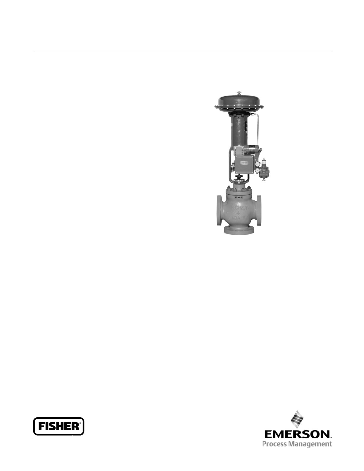
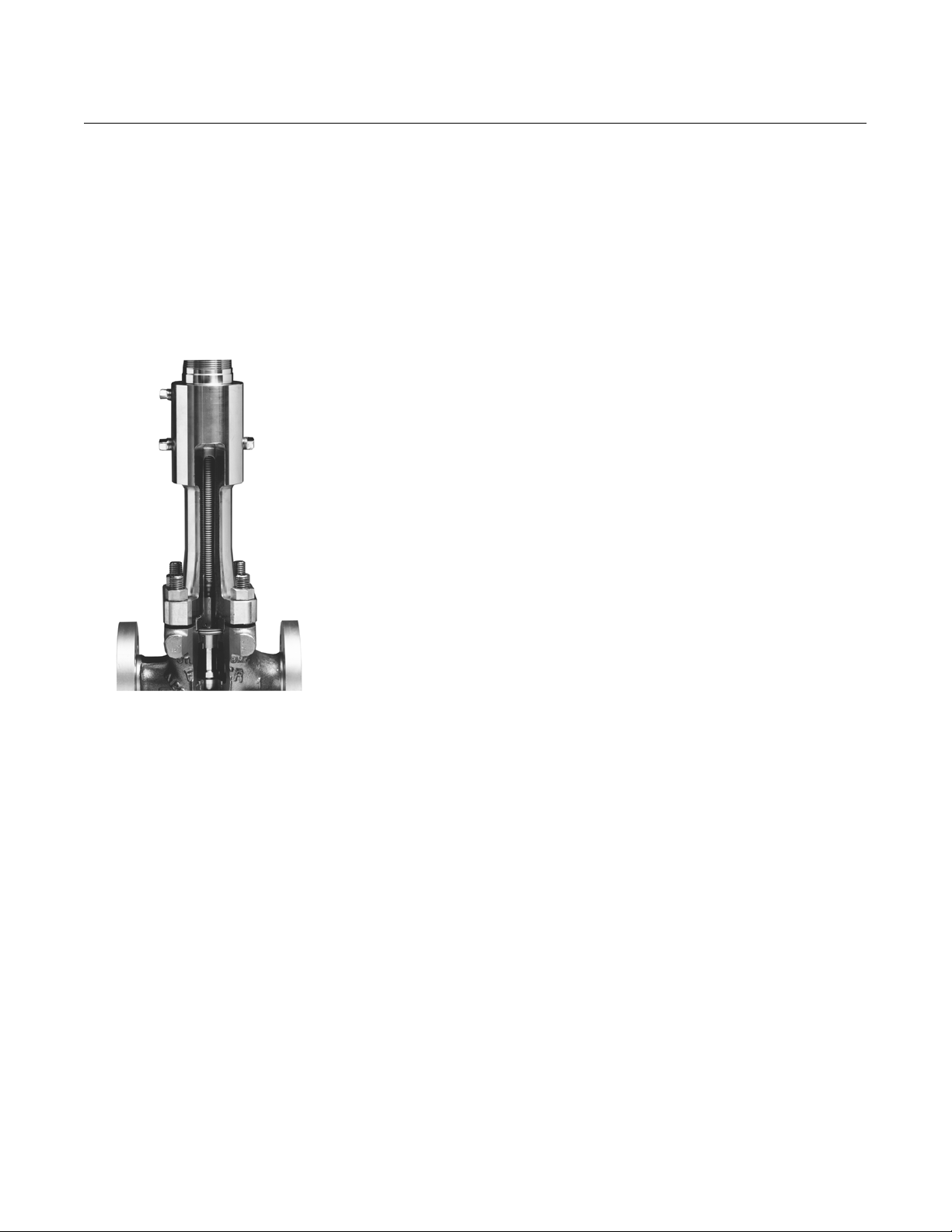
Fisherr YD and YS Control Valves
Fisher YD and YS three-way cage-guided valves are
designed for throttling or flow-switching (on-off)
service, and are available in the following
constructions:
YD (Balanced)–For general converging (flow-mixing)
and diverging (flow-splitting) service. Available in
standard and high-temperature versions (see figure 1).
YS (Unbalanced)–For general converging service.
When used in diverging service, recommended for
on-off applications only (see figure 1).
The Fisher YD and YS product lines are available for a
wide range of applications, including sulfide and
chloride stress-cracking environments common to the
oil and gas production industries. To discuss available
constructions, contact your Emerson Process
Management sales office and include the applicable
codes and standards required for these environments.
Product Bulletin
51.1:YD
June 2014
Features
Economy--Balanced valve plug construction in the
YD permits use of smaller, lower-cost actuators. A
single one-piece valve accommodates both trim
designs and uses Fisher easy-e™ bonnets, gaskets,
and packing, thus cutting spare part inventory
costs.
Application Flexibility--Multipurpose capability
results from a valve designed specifically for
three-way control. A variety of valve sizes, end
connections, port diameters, and trim materials
provides design versatility for your control needs.
Excellent Sealing Capabilities--The ENVIRO-SEAL™
packing system option is available. This packing
system provides excellent sealing, guiding, and
loading force transmission.Theimprovedsealingof
the ENVIRO-SEAL system can help control emissions
to below the EPA (Environmental Protection
Agency) limit of 100 ppm (parts per million) from
W7593
Fisher YD Valve with 667 Actuator
valves. The ENVIRO-SEAL packing systems feature
PTFE, Graphite ULF, or Duplex packing with
live-loading for reduced packing maintenance.
Long Trim Life--Hardened trim materials provide
excellent wear resistance.
Easy Maintenance--Cage-type construction
simplifies inspection and removal of parts.
Parts Commonality--Packing parts, including
packing flange, studs and nuts, and packing kits, are
common to the YD, YS, and Fisher easy-e control
valves.
Valve Plug Stability-- Rugged cage guiding provides
high valve plug stability, which reduces vibration
and mechanical noise.
www.Fisher.com
Page 2

Product Bulletin
51.1:YD
June 2014
Specifications
YD and YS Valves
D100031X012
Valve Sizes, Ratings, and End Connections
(1,2)
Cast Iron Valves
Flanged: NPS 1 through 6 CL125 flat-face or 250
raised-face flanges per ASME B16.1
Screwed: NPS 1/2 through 2 consistent with ASME
B16.4
Steel and Stainless Steel Valves
Flanged: NPS 1 through 8 CL150, 300, and 600
raised-face or ring-type joint flanges per ASME B16.5
Screwed or Socket Welding: NPS 1/2 through 2
consistent with ASME B16.11
Buttwelding: NPS 1 through 8
(5)
. All available
ASME B16.25 schedules that are consistent with
ASME B16.34
Maximum Inlet Pressures and Temperatures
(1)(2)
As listed below, unless limited by maximum pressure
drop or material temperature capabilities.
Cast Iron Valves
Flanged: Consistent with CL125B or 250B per ASME
B16.1
Screwed: Consistent with flanged CL250 per ASME
B16.4
Steel and Stainless Steel Valves
Flanged: Consistent with CL150, 300, and 600
(3)
per
ASME B16.34
Screwed or Welding: Consistent with flanged CL600
per ASME B16.34
(3)
- continued -
Operative Pressure/Temperature Limits
(1, 2)
Pressure Drop Limit Due to Gasket Loading:
See table 1
Shutoff Pressure Drop Limits with Typical A ctuators:
Seetables6,7,and8
Pressures and Temperatures for Trims Only:
Seefigure7
Temperatures for Body-Trim Combinations:
See table 5
Temperatures for All Other Parts: See table3
Shutoff Classifications per ANSI/FCI 70-2
and IEC 60534-4
YD
Standard Design: Class IV
High-Temperature Design: Class II
YS
Standard Class: Class IV
Optional Class: Class V (NPS 1 through 4)
Flow Characteristic
Linear
Flow Direction
Seefigure6
Flow Coefficients and Noise Level Prediction
Refer to Fisher Catalog 12
Table of Contents
Features 1.....................................
Specifications 2................................
ENVIRO-SEAL Packing System Specifications 4......
Flow Directions 5...............................
ENVIRO-SEAL, HIGH-SEAL Packing Systems 6........
Installation 6..................................
Tables
Travel, Port, and Gasket Loading
Pressure Drop Information 8...................
Trim Materials 8................................
Materials and Temperature Limits for Other Parts 9..
Valve Body-Trim Temperature Capabilities 10.......
2
Maximum Allowable YD Shutoff Pressure
Drops with 657 and 667 Actuators 12...........
Maximum Allowable YS
(Converging Service) Shutoff Pressure
Drops with 657 and 667 Actuators 15...........
Maximum Allowable YS
(Diverging Service) Shutoff Pressure Drops with 657
and 667 Actuators (ON-OFF) application only--
No throttling service 18.......................
Bonnet Selection Guidelines 22...................
Dimensions 22.................................
Ordering Information 22.........................
Page 3
YD and YS Valves
D100031X012
Specifications (continued)
Product Bulletin
51.1:YD
June 2014
Valve Plug Styles
YD: Balanced, metal-seated
Bonnet Styles
See table 11
YS: Unbalanced, metal-seated
Construction Materials
RatedTravelsandPortDiameters
See table 1
Valve Body and Bonnet:
bonnet),
J WCC steel, J WC9 chrome moly steel, or
J Cast iron (except extension
J CF8M (316 SST)
Yoke Boss and Stem Diameters for Actuator
Mounting
VALVE STEM AND YOKE BOSS
VALVE SIZE, NPS
Yoke Boss Stem Yoke Boss Stem
1/2, 3/4,1, 1-1/2 54 9.5 71 12.7
2, 2-1/2,3, 4 71 12.7 90 19.1
6 90 19.1 127 25.4
8 90 19.1 --- ---
1/2, 3/4,1, 1-1/2 2-1/8 3/8 2-13/16 1/2
2, 2-1/2,3, 4 2-13/16 1/2 3-9/16 3/4
6 3-9/16 3/4 5 1
8 3-9/16 3/4 --- ---
DIAMETERS, INCHES
Standard Optional
mm
Inch
Actuator Sizing
Pneumatic:Seetables6,7,and8
Electric: See Fisher Catalog 14. Electric actuators
must be capable of up and down thrust limits
1. PN (or other) ratings and end connectionscan usually be supplied; consultyour Emerson Process Management sales office.
2. The pressure or temperature limits in this bulletin and any applicable standard limitations should not be exceeded. OPERATIVE LIMITS term is defined in SAMA Standard PMC20.1.
3. Certain bonnet bolting material selections may require a CL600 easy-e valve assembly to be derated.Contact your Emerson Process Management sales office for more information.
4. For additional information, see Bulletin 59.1:061 ENVIRO-SEAL and HIGH-SEAL Packing Systems for Sliding-Stem Valves.
5. BWE not available for NPS 8 with high temperature trim, see figure 2. Lower cage cannot be removed unless bottom flange adaptor is removed.
Trims: See table 2
All Other Parts: See table 3
Approximate Shipping Weights
VALVE SIZE, NPS
1/2, 3/4
1
1-1/2
2
2-1/2
3
4
6
8
SHIPPING WEIGHT
kg lb
14
18
27
39
50
68
109
227
345
Options
J Lubricator or lubricator/isolating valve for packing
lubrication
J Drilled and tapped connection in extension bonnet
for leakoff
J ENVIRO-SEAL live-loaded packing systems
30
40
60
85
110
150
240
500
760
(4)
3
Page 4
Product Bulletin
51.1:YD
June 2014
ENVIRO-SEAL Packing System Specifications
YD and YS Valves
D100031X012
Applicable Stem Diameters
J 9.5 mm (3/8 inches), J 12.7 (1/2), J 19.1 (3/4),
and
J 25.4 (1) diameter valve stems
Male and Female Adaptor Rings: Carbon-filled PTFE
V-ring
Anti-Extrusion Washer: Filled PTFE
Lantern Ring: S31600 (316 stainless steel)
Maximum Pressure/Temperature Limits
(1)
To Meet the EPA Fugitive Emission Standard of 100
(2)
PPM
For ENVIRO-SEAL PTFE and ENVIRO-SEAL Duplex packing
systems: full CL300 up to 232_C(450_F)
For ENVIRO-SEAL Graphite ULF packing system: 104 bar
(1500 psig) at 316_C(600_F)
Spring:
Packing Box Flange: S31600
Packing Follower: S31600 lined with carbon-filled PTFE
Packing Box Studs: SA193-B8M Class 2
Packing Box Nuts: S31600
Graphite ULF Packing Systems
Packing Ring: Graphite rings
Spring:
Packing Box Flange: S31600
J 17-7PH stainless steel or J N06600
J 17-7PH stainless steel or J N06600
Packing Follower: S31600 lined with carbon-filled PTFE
Construction Materials
PTFE Packing Systems
Packing Ring and Lower Wiper: PTFE V-ring
1. Refer to the valve specifications in this bulletin for pressure/temperature limits of valve p arts. Do not exceed the pressure/temperature rating of the valve. Do not exceed any applicable code
or standard limitation.
2. The Environmental Protection Agency (EPA) has set a limit of 100 parts per million (ppm) for fugitive emissions from a valve in selected VOC (VolatileOrganicCompound)services.
3. In vacuum service, reversing the ENVIRO-SEAL PTFE packing rings is not necessary.
(3)
Packing Box Studs: SA193-B8M Class 2
Packing Box Nuts: S31600
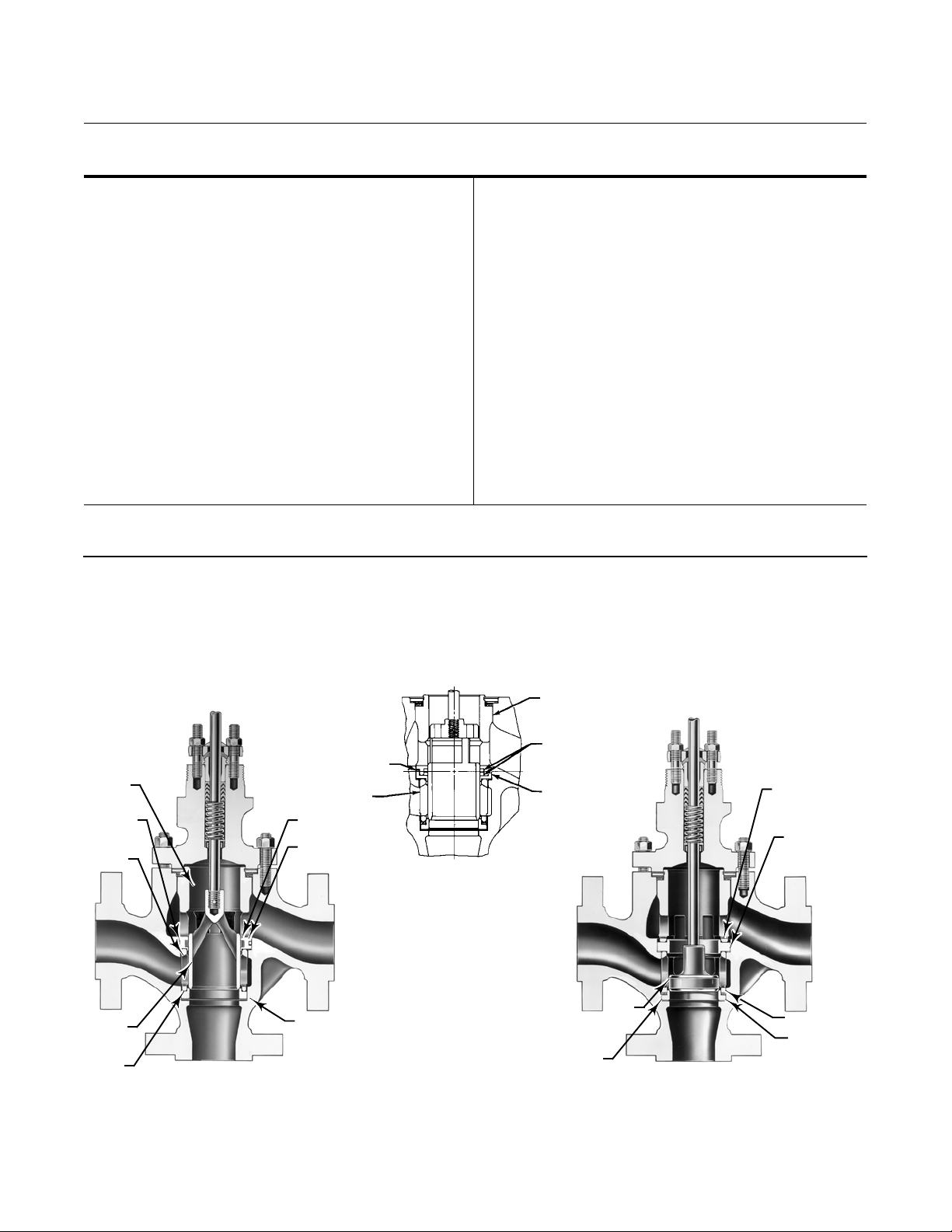
Figure 1. Construction Details
UPPER
CAGE
CAGE
O-RING
LOWER
CAGE
VALVE
PLUG
SEAT
RING
W9045-1
STANDARD YD
RETAINING
RING GASKETS
LOWER
CAGE
SEAL
RING
BACKUP
RING
SEAT RING
GASKET
40A3551-C
A1891-1
DETAIL OF HIGH TEMPERATURE
YD TRIM
UPPER
CAGE
VALVE
PLUG
SEALS
RETAINING
RING
LOWER
SEAT
RING
W9046-1
VALVE
PLUG
REVERSIBLE
UPPER
SEAT RING
UPPER
SEAT RING
GASKET
SPRING
LOWER
SEAT RING
GASKET
YS
4
Page 5
YD and YS Valves
D100031X012
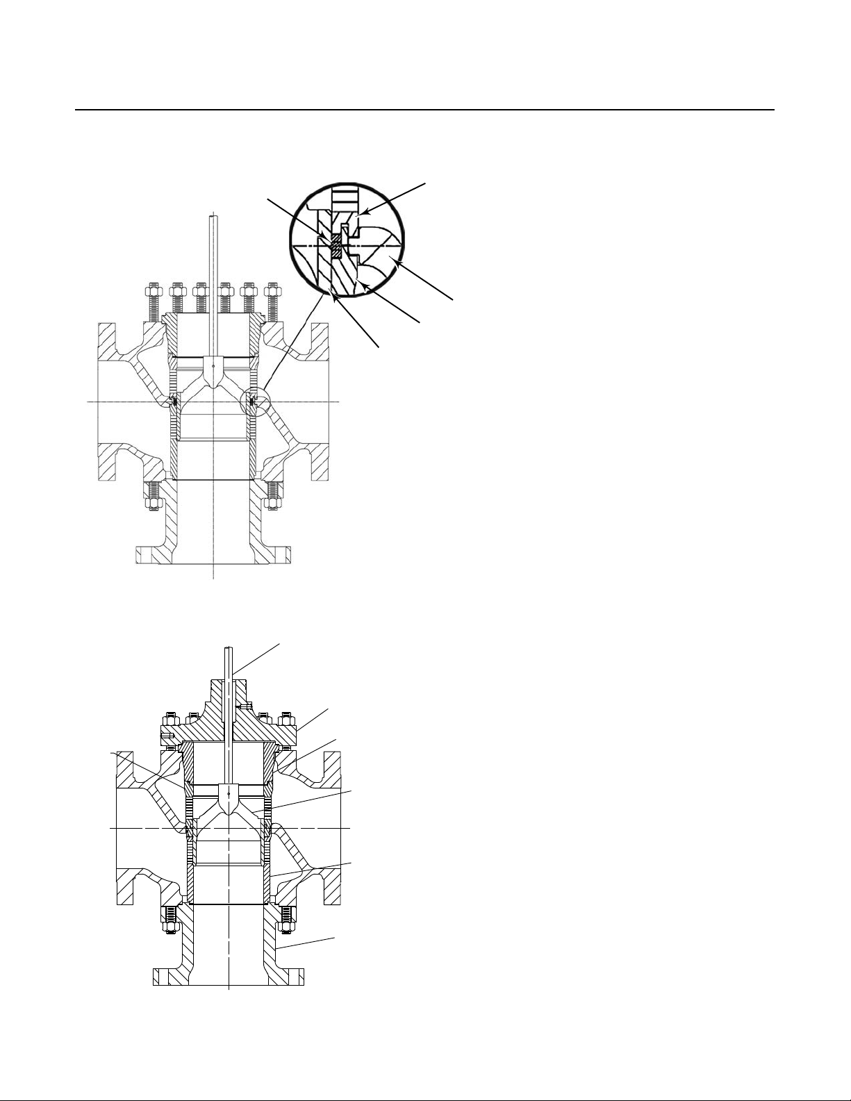
Figure 2. Construction Details - NPS 8 YD-High Temperature
GASKETS
PLUG
Product Bulletin
51.1:YD
June 2014
UPPER CAGE
VALVE BODY
LOWER CAGE
B1504-6
E1433
Figure 3. Construction Details - NPS 8 YD
STEM
UPPER
CAGE
BONNET
CAGE
ADAPTOR
PLUG
LOWER
CAGE
ADAPTOR
FLANGE
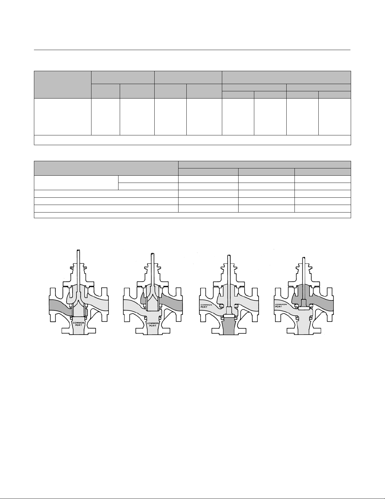
Flow Directions
YD(CommonPortonBottom)seefigure6
Plug Down, Left-Hand Port Closed--Flow in
converging service is from right to bottom port and
in diverging service is from bottom to right port.
Plug Up, Right-Hand Port Closed--Flow in
converging service is from left to bottom port and
in diverging service is from bottom to left port.
Intermediate Plug Positions-- Flow in converging
service is from both left and right ports to bottom
port, with capacities in proportion to plug travel.
Flow in diverging service is from bottom port to
both left and right ports, with capacities split in
proportion to plug travel.
YS (Common Port on Left) seefigure6
58B1505-A
Plug Down, Bottom Port Closed--Flow in converging
service is from right to left port and in diverging
service is from l eft to right port.
5
Page 6
Product Bulletin
51.1:YD
June 2014
YD and YS Valves
D100031X012
Plug Up, Right-Hand Port Closed--Flow in
converging service is from bottom to left port and
in diverging service is from left to bottom port.
Intermediate Plug Positions--Flow in converging
service is from both bottom and right ports to left
port, with capacities in proportion to plug travel.
Figure 4. Cutaway of ENVIRO-SEAL Bellows Seal
Bonnet and Internal Shroud, Showing Bellows
operational life and reliability of these systems also
reduce your maintenance costs and downtime.
For applications requiring compliance with
environmental protection regulations, the unique
ENVIRO-SEAL packing system (figure 5) and, for
hazardous service, the ENVIRO-SEAL bellows seal
system (figure 4) are offered. The emission control
packing system keeps emission concentrations below
the EPA 100 ppm requirement.
For an excellent stem seal in applications that are not
environmentally sensitive, the HIGH-SEAL Graphite
ULF packing system (figure 5) is offered. The
HIGH-SEAL packing system provides excellent sealing
at pressure/temperature ratings beyond ENVIRO-SEAL
limits. ENVIRO-SEAL systems may also be applied for
excellent stem sealing in higher pressure/temperature
applications not requiring EPA compliance.
ENVIRO-SEAL packing systems, available with PTFE,
Graphite ULF, or Duplex packing, and the HIGH-SEAL
Graphite ULF packing system feature live-loading and
unique packing-ring arrangements for long-term,
consistent sealing performance.
W5852-1
ENVIRO-SEAL, HIGH-SEAL
Packing Systems
ENVIRO-SEAL and HIGH-SEAL packing systems offer
excellent sealing capabilities. These systems easily
install i n your existing valves or can be purchased with
new valves. These systems help you seal your process
to conserve valuable process fluid. The long
Installation
Although YD and YS valves may be mounted with the
actuator in any position relative to the valve, the
normal position is with the valve in a horizontal run of
pipe and the actuator vertical above the valve. The
actuator should be supported in any position other
than vertical. Orient the valve so that valve plug
positions and flow directions will conform to the flow
indicator plate on the valve body.
Dimensions are shown in figure 8.
Note: For the NPS 8 high temperature construction,
thebottomflangeMUSTberemovedtoaccessand
remove the lower cage (see figure 2). BWE end
connections are not available for the NPS 8 high
temperature constructions for this reason.
6
Page 7
YD and YS Valves
D100031X012
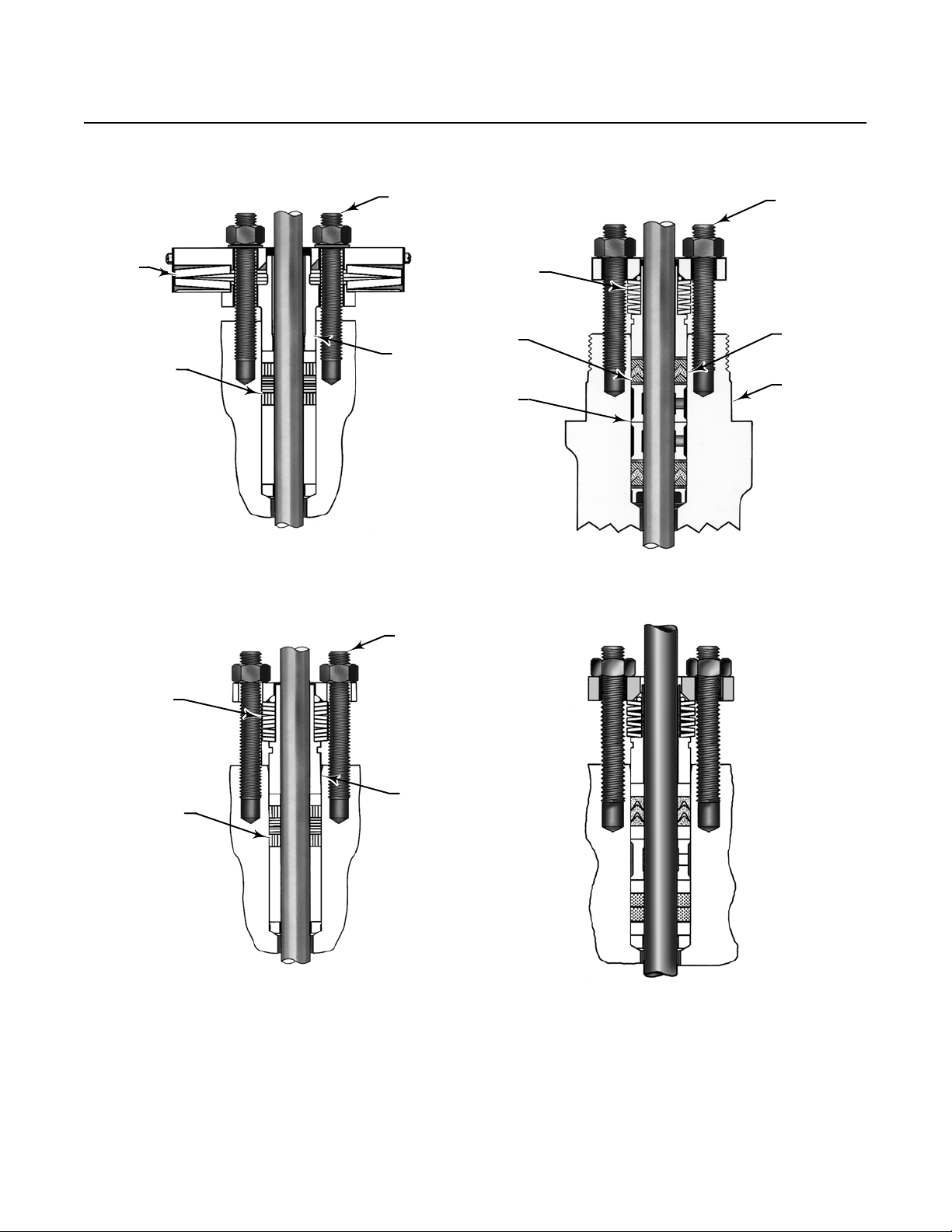
Figure 5. ENVIRO-SEAL and HIGH-SEAL Packing Systems
PACKING
BOX
STUD
Product Bulletin
51.1:YD
June 2014
PACKING
BOX
STUDS
SPRING
W8533-1
SPRINGS
PACKING
TYPICAL HIGH-SEAL PACKING SYSTEM
WITH GRAPHITE ULF PACKING
FOLLOWER
PACKING
BOX
STUD
SPRINGS
ANTIEXTRUSION
RING
LANTERN
RING
W5803-3
PACKING
RING
VALVE
BONNET
TYPICAL ENVIRO-SEAL PACKING SYSTEM
WITH PTFE PACKING
PACKING
W8532-1
FOLLOWER
TYPICAL ENVIRO-SEAL PACKING SYSTEM
WITH GRAPHITE ULF PACKING
W7018
TYPICAL ENVIRO-SEAL PACKING SYSTEM
WITH DUPLEX PACKING
7
Page 8
Product Bulletin
51.1:YD
June 2014
Table 1. Travel, Port, and Gasket Loading Pressure Drop Information
MAXIMUM
VALVE SIZE,
NPS
1/2, 3/4, 1, 1-1/2
2, 2-1/2
3
4
6
(2)
8
1. For standard YD only. For high temperature YD, consult your Emerson Process Management sales office.
2. NPS 8 only available in YD construction.
RATED TRAVEL
mm Inches mm Inches
19
29
38
51
51
57.2
0.75
1.125
1.5
2
2
2.25
SEAT RING
PORT DIAMETER
33.3
58.7
87.3
111.1
177.8
177.8
1.3125
2.3125
3.4375
4.375
7
7
PRESSURE DROP LIMIT
DUE TO GASKET LOADING
YS YD
bar psig bar psig
41.4
31.7
37.9
38.6
52.4
---
600
460
550
560
760
---
Table 2. Trim Materials
PART
Valve Plug
Upper Cage and Lower Cage CB7Cu-1 CF8M, ENC CF8M, ENC
Upper Cage Retaining Ring (High-Temperature YD Only) S41600 CF8M CF8M
Upper Seat Ring (YS Only) and Lower Seat Ring S41600 S31600 S31600/CoCr-A
1. Standard trim for stainless steel valves.
YD CB7Cu-1(17-4PH SST) CF8M (316 SST) CF8M/CoCr-A
YS S41600 (416 SST) S31600 (316 SST) CF8M/CoCr-A
Trim 1 Trim 2
MATERIAL
(1)
YD and YS Valves
D100031X012
(1)
103.4 1500
Trim 2A
Figure 6. Flow Directions
10A8391-A
YD
PLUG DOWN
B2413
10A8391-A 10A8392-A
YD
PLUG UP
YS
PLUG DOWN
10A8392-A
YS
PLUG UP
8
Page 9

Product Bulletin
YD and YS Valves
D100031X012
Table 3. Materials and Temperature Limits for Other Parts
IN-BODY PROCESS TEMPERATURE
PART MATERIAL
Cast iron body
WCC body
Cap
screws
Steel SAE Grade 5 -29 232 -20 450
Studs Steel SA-193-B7
Nuts SteelSA-194-2H
Studs Steel SA-193-B7 (std)
Body-to-bonnet
bolting. See
table 4
for NACE
bolting
materials
and
temperatures
316 stainless steel (CF8M)
Nuts SteelSA-194-2H (std)
Studs 304 stainless steel SA-320-B8
Nuts 304 stainless steel SA-194-8
Studs
316 stainless steel SA-193-B8M
(strain-hardened)
Nuts 316 stainless steel SA-194-8M
Studs
316 stainless steel SA-194-B8M
(annealed)
Nuts 316 stainless steel SA-194-8M
LCC body
Studs Steel SA-193-B7
Nuts SteelSA-194-2H
Valve plug stem and pin S31600 (316 SST) -254 --Plug-cage seals
(YD only)
Standard
YD
Cage O-ring and
backup ring
Ethylene propylene
(3)
Nitrile
Fluorocarbon
(2)
With hydrocarbons, air -34 71 -30 160
With other process fluids -34 82 -30 180
(4)
Seal ring Carbon-filled PTFE -73 232 -100 450
High-temperature
YD
Valve plug seals Graphite -254 --Retaining ring
gaskets
FGM Graphite/S31600 -254 ---
Bonnet gasket FGM Graphite/S31600 -254 ---
Retaining ring gaskets (High-temperature YD only) FGM Graphite/S31600 -254 ---
Spiral wound gaskets N06600/graphite FGM-standard -198 ---
Spiral wound spring
Packing (temperatures calculated for
standard bonnet)
NPS 1 to 3 N06600/graphiteFGM -198 --NPS 4 to 8 N06600 -198 --Standard PTFE V-ring -40 232 -40 450
Optional
PTFE/composition -73 232 -100 450
Graphite ribbon/filament -254 --Packing flange, studs, and nuts 316SST -254 ---
Packing box ring 316 SST -254 ---
All other metal packing box parts 316 SST -254 ---
1. Maximum temperature of this part not a limiting factor.
2. Has excellent moisture resistance with hot water and steam and may be used with most fire-resistant hydraulic oils, but cannot be used with petroleum-based fluids and other hydrocarbons.
3. General-purpose material with good resistance to petroleum-based lubricating oils, gasoline, and other hydrocarbons. Not for use with fire-resistant hydraulic oils.
4. For high-temperature air, hydrocarbons, and certain other chemicals and solvents, but cannot be used with ammonia, steam, or hot water.
_C _ F
Min Max Min Max
-29 427
-48 427
(1)
(1)
-198 38 -325 100
-198
(2)
427
(1)
These
mat'ls
(2)
-198
not
limiting
factors
-46 343
(1)
(1)
-40 232 -40 450
-18 204 0 400
(1)
(1)
(1)
(1)
(1)
(1)
(1)
(1)
(1)
(1)
(1)
51.1:YD
June 2014
-20 800
-55 800
(2)
-325
-325
-50 650
-425 ---
-425 ---
-425 ---
-425 ---
-425 ---
-325 ---
-325 ---
-325 ---
-425 ---
-425 ---
-425 ---
-425 ---
800
These
mat'ls
(2)
not
limiting
factors
(1)
(1)
(1)
(1)
(1)
(1)
(1)
(1)
(1)
(1)
(1)
(1)
(1)
(1)
(1)
(1)
9
Page 10

Product Bulletin
51.1:YD
June 2014
Table 4. Bolting Materials and Temperature Limits for Bolting Compliance with NACE Specification MR0175-2002,
MR0157/ISO 15156, and MR0103
TEMPERATURE CAPABILITIES
VALVE BODY MATERIAL BOLTING MATERIAL
NACE MR0175-2002, MR0157/ISO 15156, and MR0103 (non-exposed bolting) (Standard)
WCC and CF8M
(316 SST)
Studs Steel SA-193-B7
Nuts Steel SA-194-2H
-48
NACE MR0175-2002 (exposed bolting) (Optional)
No Derating of Valve Required
WCC and CF8M
WCC and CF8M
1. Special heat treating required.
2. Derating is not required for CL300 valves. Derating may be required for valves rated at CL600. Contact your Emerson Process Management sales office for assistance in determining the
derating of valves when these body-to-bonnet bolting materials are used.
3. WCC is limited to -29_C(-20_F).
Studs Steel SA-564-630 (H1150 dbl
Nuts Steel SA-194-2HM
NACE MR0175-2002, MR0157/ISO 15156, and MR0103 (exposed bolting) (Optional)
Requires Derating of Valve
(2)
When These Body-to-Body Bolting Materials are Used
Studs Steel SA-193-B7M
Nuts Steel SA-194-2HM
(1)
)
-46
-48
_C _F
Min Max Min Max
(3)
(3)
(3)
427 -55
343 -50
427 -55
YD and YS Valves
D100031X012
(3)
(3)
(3)
800
650
800
Table 5. Valve Body-Trim Temperature Capabilities
VALVE
BODY
MATERIAL
Cast Iron
TRIM
NUMBER
FROM
TABLE 2
(3)
1 -73 - 100 232 (450) 232 (450)
(2)
2
and 2A -73 - 100
Minimum Maximum
_C _F
NPS 1-1/2 to 3: 232 (450)
(1)
NPS 4 to 6: 177 (350)
WCC Steel
and WC9
Chrome
Moly Steel
1 -29 -20
(2)
2
-29 -20
NPS 1/2 to 1-1/2: 427 (800)
NPS 2 and 2-1/2: 371 (700)
NPS 3: 316 (600)
NPS 4 and 6: 260 (500)
NPS 1/2 to 1-1/2: 316 (600)
NPS 2 and 2-1/2: 232 (450)
NPS 3: 204 (400)
NPS 4 and 6: 149 (300)
2A -29 -20
NPS 1/2 to 1-1/2: 343 (650)
NPS 2 and 2-1/2: 232 (450)
NPS 3: 204 (400)
NPS 4 and 6: 149 (300)
CF8M
(316 SST)
NPS 8 YD
(2)
2
2A - 198
- 254 - 425 316 (600)
(5)
- 325
(5)
343 (650)
1 -29 -20 232 (450) 427 (800)
(4)
(4)
(WCC)
NPS 8 YD
(CF8M)
1. Refer to table 2 for trim materials.
2. Trim 2 limited to 149_C(300_F) maximum for nonlubricating fluids.
3. Cast iron is limited to -73_C (-100_F) minimum
4. Plug cage seals limit this design to 232_C(450_F) maximum.
5. May be used down to -254_C (-425_F) if manufacturing process includes Charpy impact test.
6. Only available in YD constructions.
(2)
2
- 198 - 325 232 (450) 316 (600)
2A - 198 - 325 232 (450) 343 (650)
TEMPERATURE
Standard YD
(2)
High-Temperature YD
_C(_F) _C(_F)
232 (450)
(4)
(4)
(4)
(4)
(4)
(4)
427 (800)
316 (600)
343 (650)
316 (600)
343 (650)
(6)
(6)
(6)
YS and
10
Page 11

YD and YS Valves
D100031X012
Figure 7. Maximum Allowable Pressure Drops and Temperatures for Table 2 Trims
1,2A
PRESSURE DROP, PSI
1
Product Bulletin
51.1:YD
June 2014
FLUID TEMPERATURE, _F
10A8091-B
A1892-3
Note:
1
Trim 2 limited to 149C (300F) maximum for nonlubricating fluids
650
11
Page 12

Product Bulletin
51.1:YD
June 2014
YD and YS Valves
D100031X012
Table 6. Maximum Allowable Fisher YD Shutoff Pressure Drops with 657 and 667 Actuators
NOMINAL (ACTUAL) AIR TO DIAPHRAGM, PSIG
PACKING TYPE ACTUATOR SIZE
Standard
Single or
Double PTFE
ENVIRO-SEAL PTF E
ENVIRO-SEAL
Graphite ULF
Graphite Ribbon/
Filament (CL600)
ENVIRO-SEAL
Graphite ULF
Standard
Single or
Double PTFE
ENVIRO-SEAL PTF E
ENVIRO-SEAL
Graphite ULF
Graphite Ribbon/
Filament (CL600)
30
34
30
34
30 --- --- --- --- --- ---
34 --- --- ---
30 --- --- ---
34
30 --- --- ---
34 --- --- ---
40
45
40 --- --- ---
45
45 --- --- ---
46
40 --- --- ---
45
1.3125 Inch Port, Class IV Seat Leakage
100
(5-13)
1F1768
1130
(5-13)
1E8053
290
(7-11)
1J1722
500
(5-13)
1E8053
1.3125 Inch Port, Class II Seat Leakage (High-Temperature Trim)
110
(5-13)
1E8053
2.3125 Inch Port, Class IV Seat Leakage
250
(6-12)
1F1771
275
(4-14)
1E8270
330
(5-12)
1E8269
385
(6-12)
1E8266
2.3125 Inch Port, Class II Seat Leakage (High-Temperature Trim)
300
(5-12)
1E8269
3-15 (0-18) 6-30 (0-33) 3-40(0-43)
nP, PSID/(Bench Set, PSIG)/Spring Drawing Number
500
(6-12)
1F1767
1500
(6-12)
1E8056
--- ---
1125
(6-12)
1E8056
740
(6-12)
1E8056
--- ---
820
(5-12)
1E8269
870
(6-11)
1F1773
--- ---
840
(6-11)
1F1773
-continued-
925
(7-11)
1J1722
---
---
1370
(7-11)
1F1771
1350
(6-11)
1F1773
---
---
(3)
500
(6-26)
1E7953
1500
(6-26)
1E8051
710
(8-24)
1J2581
1125
(6-26)
1E8051
955
(10-22)
1E8058
320
(8-24)
1J2581
740
(6-26)
1E8051
30
(11-21)
1F1769
450
(8-24)
1E8055
250
(6-26)
1E8054
1350
(6-26)
1E8263
120
(7-25)
1E8058
865
(6-26)
1E8263
430
(9-24)
1E8268
385
(6-26)
1E8258
90
(7-25)
1E8058
840
(6-26)
1E8263
(8-24)
1J2581
(10-22)
1E7923
(8-24)
1E8055
(12-20)
1E8053
(11-21)
1F1769
(8-24)
1J2581
(12-20)
1F1768
(10-22)
1E8058
(7-25)
1E8058
(8-25)
1E8271
(9-24)
1E8057
(8-25)
1E8271
(11-22)
1E8272
(8-24)
1E8264
(9-24)
1E8057
(8-25)
1E8271
(1)
(2)
1335
--- --- ---
1500
1500
1500
1500
1500
450
1500
600
1500
820
1500
1500
1500
790
1500
1500
(10-22)
1E7923
--- ---
--- ---
---
--- ---
--- ---
---
--- ---
1500
(10-22)
1E8053
--- ---
1170
(10-22)
1E8053
--- ---
--- ---
--- ---
1145
(10-22)
1E8053
--- ---
(14-28)
1F7143
(13-29)
1E8055
(14-28)
1F7143
(12-30)
1E8058
(12-30)
1E8058
---
540
1500
1300
---
1500
1500
12
Page 13

YD and YS Valves
D100031X012
Product Bulletin
51.1:YD
June 2014
Table 6. Maximum Allowable Fisher YD Shutoff Pressure Drops with 657 and 667 Actuators
NOMINAL (ACTUAL) AIR TO DIAPHRAGM, PSIG
PACKING TYPE ACTUATOR SIZE
2.3125 Inch Port, Class II Seat Leakage (High-Temperature Trim) (Continued)
40 --- --- --- --- --- ---
ENVIRO-SEAL
Graphite ULF
Standard
Single or
Double PTFE
ENVIRO-SEAL PTFE
ENVIRO-SEAL
Graphite ULF
Graphite Ribbon/
Filament (CL600)
ENVIRO-SEAL
Graphite ULF
Standard
Single or
Double PTFE
ENVIRO-SEAL PTFE
ENVIRO-SEAL
Graphite ULF
45 --- --- ---
46
40 --- --- --- --- --- ---
45
45
46
45 --- --- ---
46 --- --- ---
40 --- --- --- --- --- ---
45
45 --- --- ---
46
45
46
45 --- --- ---
46
45 --- --- --- --- --- ---
46 --- --- ---
330
(5-13)
1E8272
3.4375 Inch Port, Class IV Seat Leakage
100
(5-12)
1F1773
150
(6-11)
1E9215
150
(4-14)
1E8272
3.4375 Inch Port, Class II Seat Leakage (High-Temperature Trim)
500
(6-11)
1E9215
770
(6-12)
1E8269
4.375 Inch Port, Class IV Seat Leakage
50
(6-12)
1E9215
800
(5-13)
1E8269
325
(5-13)
1E8269
3-15 (0-18) 6-30 (0-33) 3-40(0-43)
nP, PSID/(Bench Set, PSIG)/Spring Drawing Number
635
(8-25)
1125
(6-12)
1E8266
650
(3)
(6-11)
1E9215
(3)
(3)
(3)
--- ---
1500
(6-12)
1E8269
--- ---
--- ---
--- ---
--- ---
--- ---
-continued-
---
---
---
1E8271
1125
(6-12)
1E8258
650
(6-26)
1E8268
150
(6-26)
1E8268
1500
(6-26)
1E8267
250
(10-22)
1E8266
460
(7-25)
1E8263
500
(6-26)
1E8268
815
(9-24)
1E8272
770
(6-26)
1E8267
50
(6-26)
1E8272
1500
(6-26)
1E8271
80
(7-25)
1E8270
1125
(6-26)
1E8271
260
(7.5-21)
1E8272
(11-22)
1E8272
(8-24)
1E8264
(9-24)
1E8272
(9-24)
1E8272
(11-20)
1E8269
(9-24)
1E8271
(9-24)
1E8272
(11-20)
1E8269
(7-25)
1E8263
(7-25)
1E8270
(8-24)
1E8266
(7-23)
1E8265
(1)
(continued)
(2)
(12-30)
1500
1500
1500
1500
--- --- ---
800
1500
1500
1500
1500
570
--- --- ---
620
1500
--- --- ---
--- ---
--- ---
--- ---
--- ---
---
--- ---
--- ---
--- ---
--- ---
1100
(8-24)
1E8266
---
--- ---
1E8058
1E8058
(13-29)
1E8261
1E8058
1E8265
1E8265
(11-31)
1E8272
575
230
(8-32)
1500
85
(8-32)
1500
(9-33)
1150
(9-33)
200
13
Page 14

Product Bulletin
51.1:YD
June 2014
YD and YS Valves
D100031X012
Table 6. Maximum Allowable Fisher YD Shutoff Pressure Drops with 657 and 667 Actuators
NOMINAL (ACTUAL) AIR TO DIAPHRAGM, PSIG
PACKING TYPE ACTUATOR SIZE
4.375 Inch Port, Class II Seat Leakage (High-Temperature Trim)
200
45
Graphite Ribbon/
Filament (CL600)
ENVIRO-SEAL
Graphite ULF
Standard
Single or
Double PTFE
ENVIRO-SEAL PTF E
ENVIRO-SEAL
Graphite ULF
Graphite Ribbon/
Filament (CL600)
ENVIRO-SEAL
Graphite ULF
1. Spring and bench sets selected for use with either 657 or 667. Other acceptable configurations possible from Fisher Specification Manager for a specific actuator type.
2. The bench set values shown assume an actual supply pressure to the actuator of 0 to 18 psig for a nominal 3 to 15 psig signal, an actual 0 to 33 psig supply for a nominal 6 to 30 psig signal,
and an actual 0 to 43 psig supply for a nominal 3 to 40 psig signal. Any positioner or controller used with these actuators must be capable of delivering the appropriate slightly extended range.
3. Requires non-standard spring adjustor.
4. Special Class IV seat load (40 lb/lineal inch) used for YD with 7-inch diameter port.
46
45 --- --- ---
46
50 --- --- --- --- --- ---
60 --- --- ---
70
50 --- --- --- --- --- ---
60 --- --- ---
70 --- --- ---
76
(667 only)
70 --- --- ---
NPS 6, 7 Inch Port, Class II Seat Leakage (High-Temperature Trim)
50 --- --- --- --- --- ---
60 --- --- ---
70 --- --- ---
76
(667 only)
70 --- --- ---
(6-12)
1E9215
950
(5-13)
1E8269
70
(5.5-11.5)
1F1773
NPS 6, 7 Inch Port, Class IV Seat Leakage
250
(5-13)
1N1286
--- --- --- --- --- ---
--- --- ---
3-15 (0-18) 6-30 (0-33) 3-40(0-43)
nP, PSID/(Bench Set, PSIG)/Spring Drawing Number
(4)
200
(6-26)
1E8272
1500
(6-26)
1E8271
250
(8.5-24.5)
1E8266
470
(6-26)
1E8271
405
(7.5-21)
1E8272
750
(6-26)
1N7193
95
(7.5-21)
1E8272
430
(6-26)
1N7193
590
(10-22)
1N1284
160
(7.5-21)
1E8272
500
(6-26)
1N7193
490
(11-22)
1N1286
590
(8-23)
1N1287
(3)
(3)
--- ---
--- ---
--- ---
--- ---
(1)
(continued)
(2)
720
(7-25)
1E8270
--- --- ---
--- ---
1260
(7-23)
1E8265
--- --- ---
1500
(8-23)
1N1287
--- --- ---
1450
(8-23)
1N1287
--- ---
--- --- ---
1500
(8-23)
1N1287
--- ---
1500
(10-22)
1N1284
1250
(8-24)
1E8266
1500
(7.5-21)
1E8272
--- ---
1500
(10-22)
1N1284
--- ---
--- ---
1500
(9-33)
1E8265
520
(9-33)
1E8265
370
(11-31)
1E8272
(11-31)
1E8272
200
(13-29)
1N1284
1500
(13-28)
1N1287
125
(11-31)
1E8272
1200
(13-29)
1N1284
---
60
---
14
Page 15

YD and YS Valves
D100031X012
Product Bulletin
51.1:YD
June 2014
Table 7. Maximum Allowable Fisher YS (Converging Service) Shutoff Pressure Drops with 657 and 667 Actuators
180
350
125
300
180
80
250
61
(9-24)
188
55
165
95
130
(9-24)
40
151
(2)
245
(12-20)
1F1768
450
(12-20)
1E8053
195
(12-20)
1F1768
400
(12-20)
1E8053
---
150
(12-20)
1F1768
350
(12-20)
1E8053
78
(10-22)
1E8053
213
(12-21)
1E8266
---
190
(12-21)
1E8266
---
240
(12-21)
1E8265
---
176
(12-21)
1E8266)
1E8054
1E8054
1E8054
1E8054
1E8058
1E8265
1E8058
1E8265
1E8265
(667 Only)
1E8263
1E8058
1E8265
PACKING TYPE ACTUATOR SIZE
Standard
Single or
Double PTFE
ENVIRO-SEAL PTF E
ENVIRO-SEAL
Graphite ULF
Graphite Ribbon/
Filament (CL300)
Standard
Single or
Double PTFE
ENVIRO-SEAL PTF E
ENVIRO-SEAL
Graphite ULF
Graphite Ribbon/
Filament (CL300)
30
34
30
34
30 --- --- --- --- --- ---
34 --- --- ---
30 --- --- ---
34
40
45
40 --- --- ---
45
45 --- --- ---
46
40 --- --- ---
45
NOMINAL (ACTUAL) AIR TO DIAPHRAGM, PSIG
3-15 (0-18) 6-30 (0-33) 3-40(0-43)
nP, PSID/(Bench Set, PSIG)/Spring Drawing Number
1.3125 Inch Port, Class IV Seat Leakage
40
(6-12)
1F1767
95
(5-13)
1E8053
25
(3)
(7-11)
1J1722
40
(5-13)
1E8053
45
(6-12)
1E8056
2.3125 Inch Port, Class IV Seat Leakage
12
(6-12)
1F1771
38
(5-12)
1E8269
15
(5-12)
1E8269
18
(6-12)
1E8266
26
(6-11)
1F1773
75
(3)
(7-11)
1J1722
145
(6-12)
1E8056
--- ---
95
(6-12)
1E8056
95
(7-11)
1F1771
--- ---
63
(6-11)
1F1773
40
(6-11)
1F1773
--- ---
--- ---
-continued-
---
195
(7-11)
1F1771
145
(7-11)
1F1771
---
---
---
110
(8-24)
1J2581
245
(8-24)
1E8055
60
(8-24)
1J2581
195
(8-24)
1E8055
80
(10-22)
1E8058
10
(8-24)
1J2581
145
(8-24)
1E8055
28
(7-25)
1E8058
113
(8-25)
1E8271
38
(9-24)
1E8057
90
(8-25)
1E8271
70
(11-22)
1E8272
55
(7-25)
1E8257
24
(9-24)
1E8057
76
(8-25)
1E8271
(10-22)
1E7923
(10-22)
1E8058
(10-22)
1E7923
(10-22)
1E8058
(12-20)
1E8053
(10-22)
1E7923
(10-22)
1E8058
1E8057
(11-22)
1E8272
(10-22)
1E8053
(11-22)
1E8272
(12-21)
1E8266
1E8267
(10-22)
1E8053
(11-22)
1E8272
(1)
315
(14-28)
1F7143
550
(14-28)
265
(14-28)
1F7143
500
(14-28)
45
(14-28)
1F7143
285
(14-28)
215
(14-28)
1F7143
450
(14-28)
110
(12-30)
263
(14-28)
88
(12-30)
240
(14-28)
145
(14-28)
315
(14-28)
73
(12-30)
226
(14-28)
15
Page 16

Product Bulletin
51.1:YD
June 2014
YD and YS Valves
D100031X012
Table 7. Maximum Allowable Fisher YS (Converging Service) Shutoff Pressure Drops with 657 and 667 Actuators
(continued)
(2)
47
(9-24)
1E8272
114
(10-22)
1E8265
37
(9-24)
1E8272
103
(10-22)
1E8265
--- ---
60
(10-22)
1E8265
31
(9-24)
1E8272
97
(10-22)
1E8265
--- ---
36
1E8272
70
(3)
88
(9-24)
--- ---
30
1E8272
61
(3)
79
(9-24)
70
(11-20)
1E8269
130
(11-21)
1E8261
60
(11-20)
1E8269
120
(11-22)
1E8261
77
(11-21)
1E8261
53
(11-20)
1E8269
114
(11-21)
1E8261
--- ---
---
102
(10-22)
1N1284
--- ---
---
93
(10-22)
1N1284
PACKING TYPE ACTUATOR SIZE
40 --- --- --- --- --- ---
Standard
Single or
Double PTFE
ENVIRO-SEAL PTFE
ENVIRO-SEAL
Graphite ULF
Graphite Ribbon/
Filament (CL300)
Standard
Single or
Double PTFE
ENVIRO-SEAL PTFE
ENVIRO-SEAL
Graphite ULF
45
46
45
46
45 --- --- ---
46 --- --- ---
45 --- --- ---
46
45 --- --- ---
46
(4)
76
(667 Only)
(4)
70
45 --- --- ---
46
(4)
76
(667 Only)
(4)
70
(4)
76
(667 Only)
NOMINAL (ACTUAL) AIR TO DIAPHRAGM, PSIG
3-15 (0-18) 6-30 (0-33) 3-40(0-43)
nP, PSID/(Bench Set, PSIG)/Spring Drawing Number
3.4375 Inch Port, Class IV Seat Leakage
13
(6-11)
1E9215
30
(5-13)
1E8266
5
(6-11)
1E9215
19
(5-13)
1E8266
13
(5-13)
1E8266
(3)
(3)
--- ---
46
(6-12)
1E8269
--- ---
36
(6-12)
1E8269
30
(6-12)
1E8269
---
---
---
25
(7-25)
1E8265
80
(8-24)
1E8262
15
(7-25)
1E8265
70
(8-24)
1E8262
17
(11-20)
1E8269
27
(8-24)
1E8262
8
(7-25)
1E8265
63
(8-24)
1E8262
4.375 Inch Port, Class IV Seat Leakage
15
(8-24)
16
(5.5-11.5)
1F1773
--- --- ---
29
(5-13)
1N1286
9
(5.5-11.5)
1F1773
--- --- ---
20
(5-13)
1N1286
--- --- --- --- --- ---
--- ---
--- ---
--- ---
--- ---
-continued-
1E8266
21
(6-26)
1E8271
39
(8-24)
1N1284
44
(6-26)
1N7193
8
(8-24)
1E8266
14
(6-26)
1E8271
30
(8-24)
1N1284
35
(6-26)
1N7193
(7.5-21)
(11-22)
1N1286
1N1287
(7.5-21)
(11-22)
1N1286
1N1287
(1)
5
(8-32)
1E8058
104
(14-29)
1E8272
(667 Only)
147
(12-27)
1E8271
94
(14-29)
1E8272
(667 Only)
137
(12-27)
1E8271
50
(14-29)
1E8272
(667 Only)
94
(12-27)
1E8271
87
(14-29)
1E8272
(667 Only)
130
(12-27)
1E8271
35
(11-31)
1E8272
112
(3)
(15-26)
1N1286
161
(14-29)
1N1287
29
(11-31)
1E8272
102
(3)
(15-26)
1N1286
152
(14-29)
1N1287
85
(3)
(15-26)
1N1286
16
Page 17

YD and YS Valves
D100031X012
Product Bulletin
51.1:YD
June 2014
Table 7. Maximum Allowable Fisher YS (Converging Service) Shutoff Pressure Drops with 657 and 667 Actuators
(1)
(continued)
NOMINAL (ACTUAL) AIR TO DIAPHRAGM, PSIG
PACKING TYPE ACTUATOR SIZE
3-15 (0-18) 6-30 (0-33) 3-40(0-43)
nP, PSID/(Bench Set, PSIG)/Spring Drawing Number
4.375 Inch Port, Class IV Seat Leakage (Continued)
ENVIRO-SEAL
Graphite ULF
Graphite Ribbon/
Filament (CL300)
(4)
70
45 --- --- ---
46
(4)
76
(667 Only)
(4)
70
--- --- ---
5
(5.5-11.5)
1F1773
--- --- ---
7
(5-13)
1N1286
--- ---
--- ---
NPS 6, 7-Inch Port, Class IV Seat Leakage
60 --- --- ---
76
Standard
Single or
Double PTFE
ENVIRO-SEAL PTFE
ENVIRO-SEAL
Graphite ULF
Graphite Ribbon/
Filament (CL300)
1. Spring and bench sets selected for use with either 657 or 667. Other acceptable configurations possible from Fisher Specification Manager for a specific actuator type
2. The bench set values shown assume an actual supply pressure to the actuator of 0 to 18 psig for a nominal 3 to 15 psig signal, an actual 0 to 33 psig supply for a nominal 6 to 30 psig signal,
and an actual 0 to 43 psig supply for a nominal 3 to 40 psig signal. Any positioner or controller used with these actuators must be capable of delivering the appropriate slightly extended range.
3. Requires non-standard spring adjustor.
4. Oversize yoke boss required.
5. Special Class 4 seat load (40 lb/lineal inch) used for YS, 7-inch port.
(667 Only)
70
(4)
80
76
(667 Only)
70 --- --- ---
(4)
80
76
(667 Only)
70 --- --- ---
(4)
80
76
(667 Only)
70 --- --- ---
(4)
80
--- --- ---
3
(5-13)
1N1286
10
(5-13)
1H7477
--- --- ---
5
(5-13)
1H7477
--- --- --- --- --- ---
--- --- ---
--- --- ---
--- --- ---
--- ---
--- ---
--- ---
25
(9-24)
1N1287
4
(8-24)
1E8266
10
(6-26)
1E8271
17
(8-24)
1N1284
22
(6-26)
1N7193
(5)
5
(7.5-21)
1E8272
7
(8-24)
1N1284
8
(6-26)
1N7193
25
(7-26)
1H7476
15
(11-22)
1N1286
5
(6-26)
1N7193
20
(7-26)
1H7476
7
(10-22)
1N1284
7
(9-22)
1H7475
10
(11-22)
1N1286
17
(9-24)
1N1287
13
(7-26)
1H7476
1N1284
(7.5-21)
(11-22)
1N1286
1N1287
(11-22)
1N1286
1N1287
1H7473
(3)
1N1287
1H7473
(3)
1N1284
1H7473
(2)
39
(10-22)
--- ---
26
1E8272
48
(3)
66
(9-24)
--- --- ---
19
(3)
26
(9-24)
39
(8-24)
--- ---
22
(9-24)
34
(8-24)
--- ---
--- ---
--- ---
23
(10-22)
27
(8-24)
---
--- ---
---
81
(10-22)
1N1284
---
31
(10-22)
1N1284
47
(9-22)
1H7475
28
(10-22)
1N1284
42
(9-22)
1H7475
---
35
(9-22)
1H7475
(14-29)
1N1287
(11-31)
1E8272
(15-26)
1N1286
139
(14-29)
1N1287
(15-26)
1N1286
(14-29)
1N1287
(13-29)
1H7473
(15-26)
1N1286
(14-29)
1N1287
103
(13-29)
1H7473
(15-26)
1N1286
(14-29)
1N1287
(13-29)
1H7473
(15-26)
1N1286
(14-29)
1N1287
(13-29)
1H7473
99
25
90
(3)
35
(3)
54
77
31
(3)
51
10
(3)
30
36
27
(3)
46
65
17
Page 18

Product Bulletin
51.1:YD
June 2014
YD and YS Valves
D100031X012
Table 8. Maximum Allowable Fisher YS (Diverging Service) Shutoff Pressure Drops with 657 and 667 Actuators
(ON-OFF) application only–No throttling service
PACKING TYPE ACTUATOR SIZE
Standard
Single or
Double PTFE
ENVIRO-SEAL PTF E
ENVIRO-SEAL
Graphite ULF
Graphite Ribbon/
Filament (CL300)
Standard
Single or
Double PTFE
ENVIRO-SEAL PTF E
ENVIRO-SEAL
Graphite ULF
Graphite Ribbon/
Filament (CL300)
30
34
30
34
34 ---
30 ---
34
40
45
40 ---
45
45 ---
46
40 ---
45
(1)
NOMINAL (ACTUAL) AIR TO DIAPHRAGM, PSIG
3-15 (0-18) 6-30 (0-33) 3-40 (0-43)
(6)
nP
, PSID/(Bench Set, PSIG)
1.3125 Inch Port, Class IV Seat Leakage
195
(5-13)
1F1768
315
(3-15)
1E8058
145
(3)
(7-11)
1J1722
265
(5-13)
1E8053
210
(6-12)
1E8056
2.3125 Inch Port, Class IV Seat Leakage
50
(6-12)
1F1771
155
(4-14)
1E8270
120
(5-12)
1E8269
120
(6-12)
1E8266
105
(6-11)
1F1773
-continued-
(7)
/Spring Drawing Number
450
(4.5-28.5)
1E7924
600
(4.5-28.5)
1E8052
385
(8-24)
1J2581
600
(6-26)
1E8051
400
(10-22)
1E8058
330
(8-24)
1J2581
570
(6-26)
1E8051
210
(6-26)
1E8054
330
(4-28)
1E8264
190
(7-25)
1E8058
310
(6-26)
1E8263
225
(9-24)
1E8268
380
(7-25)
1E8257
280
(9-24)
1E8057
295
(6-26)
1E8263
(2)
---
---
---
---
---
---
---
---
---
---
---
---
---
---
---
18
Page 19

YD and YS Valves
D100031X012
Product Bulletin
51.1:YD
June 2014
Table 8. Maximum Allowable Fisher YS (Diverging Service) Shutoff Pressure Drops with 657 and 667 Actuators
(1)
(ON-OFF) application only–No throttling service
PACKING TYPE ACTUATOR SIZE
40 --- ---
Standard
Single or
Double PTFE
ENVIRO-SEAL PTF E
ENVIRO-SEAL
Graphite ULF
Graphite Ribbon/
Filament (CL300)
Standard
Single or
Double PTFE
ENVIRO-SEAL PTF E
ENVIRO-SEAL
Graphite ULF
Graphite Ribbon/
Filament (CL300)
45
46
45
46
45 ---
46 ---
45 ---
46
45
46
45 ---
46
45 --- ---
46 ---
(4)
70
45 ---
46
(continued)
NOMINAL (ACTUAL) AIR TO DIAPHRAGM, PSIG
3-15 (0-18) 6-30 (0-33) 3-40 (0-43)
(6)
nP
, PSID/(Bench Set, PSIG)
3.4375 Inch Port, Class IV Seat Leakage
65
(5-12)
1F1773
110
(4-14)
1E8272
55
(3)
(6-11)
1E9215
100
(4-14)
1E8272
90
(5-13)
1E8266
4.375 Inch Port, Class IV Seat Leakage
40
(3)
(6-12)
1E9215
65
(5-13)
1E8269
60
(5-13)
1E8269
---
55
(5-13)
1E8269
-continued-
(7)
/Spring Drawing Number
150
(6-26)
1E8268
225
(6-26)
1E8267
140
(6-26)
1E8268
215
(4-28)
1E8257
95
(10-22)
1E8266
170
(7-25)
1E8263
130
(7-25)
1E8265
210
(6-26)
1E8267
90
(6-26)
1E8272
140
(6-26)
1E8271
85
(7-25)
1E8270
135
(6-26)
1E8271
50
(7.5-21)
1E8272
135
(9-24)
1N1287
80
(8-24)
1E8266
130
(6-26)
1E8271
(2)
125
(8-32)
1E8058
---
---
---
---
---
---
---
---
---
---
---
---
55
(11-31)
1E8272
---
---
---
---
19
Page 20

Product Bulletin
51.1:YD
June 2014
YD and YS Valves
D100031X012
Table 8. Maximum Allowable Fisher YS (Diverging Service) Shutoff Pressure Drops with 657 and 667 Actuators
(1)
(ON-OFF) application only–No throttling service
PACKING TYPE ACTUATOR SIZE
NPS 6, 7-Inch Port, Class IV Seat Leakage
50 --- ---
Standard
Single or
Double PTFE
ENVIRO-SEAL PTF E
ENVIRO-SEAL
Graphite ULF
Graphite Ribbon/
Filament (CL300)
1. Spring and bench sets selected for use with either 657 or 667. Other acceptable configurations possible from Fisher Specification Manager for a specific actuator type
2. The bench set values shown assume an actual supply pressure to the actuator of 0 to 18 psig for a nominal 3 to 15 psig signal, an actual 0 to 33 psig supply for a nominal 6 to 30 psig signal,
and an actual 0 to 43 psig supply for a nominal 3 to 40 psig signal. Any positioner or controller used with these actuators must be capable of delivering the appropriate slightly extended range.
3. Requires non-standard spring adjustor.
4. Oversize yoke boss required.
5. Special Class 4 seat load (40 lb/lineal inch) used for YS, 7-inch port.
6. Assumes same shutoff pressure drop for top and bottom ports.
7. Bench sets selected will provide sufficient seat loading, even with no pressure drop. The selected bench sets will enable the actuator to fully stroke the valve up or down with the maximum
shutoff drop listed.
60 ---
70
50 --- ---
60 ---
70
76
(667 Only)
70 ---
76
(667 Only)
70 ---
(continued)
NOMINAL (ACTUAL) AIR TO DIAPHRAGM, PSIG
3-15 (0-18) 6-30 (0-33) 3-40 (0-43)
(6)
nP
, PSID/(Bench Set, PSIG)
35
(5-13)
1N1286
30
(5-13)
1N1286
--- ---
---
(5)
(7)
/Spring Drawing Number
45
(7.5-21)
1E8272
75
(6-26)
1N7193
40
(7.5-21)
1E8272
70
(6-26)
1N7193
50
(10-22)
1N1284
45
(3)
(11-22)
1N1286
70
(6-26)
1N7193
(2)
50
(11-31)
1E8272
---
---
45
(11-31)
1E8272
---
---
50
(13-29)
1N1284
---
---
---
20
Page 21

YD and YS Valves
D100031X012
Table 9. Fisher YD and YS Dimensions
VALVE
MATERIAL
AND SIZE,
NPS
CAST
(2)
IRON
STEEL
&SST
(2)
1/2, 3/4
(2)
1
1-1/2
2
2-1/2
3
4
6
(3)
8
(2)
1/2, 3/4
(2)
1
1-1/2
2
2-1/2
3
4
6
(3)
8
1. Abbreviations are: BWE, butt weld ends; FF, flat-face flanges; RF, raised-face flanges; RTJ, ring-type joint flanges; SWE, socket weld ends.
2. NPS 1/2, 3/4, and 1 are not available in cast iron material.
3. The NPS 8 high temperature valve is not available in a BWE construction.
Valve Rating and End Connection Style
---
---
---
---
---
8.25
8.25
9.88
---
---
---
---
---
CL125
FF
CL150RFCL150
---
184.2
222.3
254.0
276.4
298.5
352.6
450.9
543.1
---
7.25
8.75
10.00
10.88
11.75
13.88
17.75
21.38
Screwed
Screwed
&SWE
209.6
209.6
251.0
285.8
11.25
A D
(1)
CL250
---
RTJ
---
196.9
235.0
266.7
289.1
311.1
365.3
463.6
555.8
---
7.75
9.25
10.50
11.38
12.25
14.38
18.25
21.88
CL300RFCL300
RF
---
196.9
235.0
266.7
292.1
317.5
368.3
472.9
568.5
---
7.75
9.25
10.50
11.50
12.50
14.50
18.62
22.38
--- --- ---
CL600
CL600
RF &
RTJ
BWE
---
---
209.6
209.6
247.7
251.0
282.4
285.8
307.8
311.2
333.2
336.6
384.0
393.7
489.0
508.0
584.2
609.6
---
---
8.25
8.25
9.75
9.88
11.12
11.25
12.12
12.25
13.12
13.25
15.12
15.50
19.25
20.00
23.00
24.00
RTJ
---
209.6
251.0
289.1
314.5
339.9
396.7
511.0
612.9
---
8.25
9.88
11.38
12.38
13.38
15.62
20.12
24.13
DIMENSION
Standard Bonnet
Stem Diameter,
mm (Inches)
9.5
12.7
(3/8)
(1/2)
mm
127.0
149.4
127.0
149.4
127.0
149.4
---
171.5
---
171.5
---
195.3
---
228.6
---
---
---
---
Inches
5.00
5.88
5.00
5.88
5.00
5.88
---
6.75
---
6.75
---
7.69
---
9.00
---
---
---
---
19.1
(3/4)
---
---
---
168.1
168.1
192.0
225.6
242.8
323.9
---
---
---
6.62
6.62
7.56
8.88
9.56
12.75
25.4
(1)
---
---
---
---
---
---
---
287.3
---
---
---
---
---
---
---
---
11.31
---
9.5
(3/8)
212.9
212.9
212.9
---
---
---
---
---
---
8.38
8.38
8.38
---
---
---
---
---
---
Stem Diameter,
mm (Inches)
(1/2)
251.0
251.0
251.0
273.1
273.1
296.9
330.2
10.75
10.75
11.69
13.00
Product Bulletin
Extension Bonnet
Style 1 Style 2
Stem Diameter,
mm (Inches)
12.7
19.1
25.4
(1)
---
---
---
---
---
---
---
419.1
---
---
---
---
---
---
---
---
16.50
---
9.5
(3/8)
303.3
303.3
303.3
---
---
---
---
---
---
11.94
11.94
11.94
---
---
---
---
---
---
---
---
9.88
9.88
9.88
---
---
(3/4)
---
---
---
277.9
277.9
301.8
335.0
349.3
---
---
---
---
10.94
10.94
11.88
13.19
13.75
---
51.1:YD
June 2014
12.7
19.1
(1/2)
(3/4)
319.0
---
319.0
---
319.0
---
471.1
468.4
471.1
468.4
500.1
505.0
533.4
525.5
---
534.9
---
---
12.56
---
12.56
---
12.56
---
18.56
18.44
18.56
18.44
19.69
19.88
21.00
20.69
---
21.06
---
---
Table 10. Additional Dimensions for Fis her YD and YS High Temperature Valves
VALVE
MATERIAL
AND SIZE,
NPS
STEEL
&SST
(3)
8
(3)
8
Valve Rating and End Connection Style
Screwed
&SWE
CL150
RF
CL150
RTJ
--- 384.6 390.9 397.0 404.9 457.2 458.7
--- 15.14 15.39 15.63 15.94 18.00 18.06
DIMENSION
C
CL300
RF
mm
Inches
(1)
CL300
RTJ
CL600
RF &
BWE
CL600
RTJ
21
Page 22

Product Bulletin
51.1:YD
June 2014
Figure 8. Fisher YD and YS Dimensions (also see table 9)
YD and YS Valves
D100031X012
A1893A-1
A2
MATCH LINE
FOR ACTUATOR
D
A2
A2
A
A1893A-1
A
MATCH LINE
FOR ACTUATOR
D
C
NPS8YDandYSHIGHTEMPERATURE
Table 11. Bonnet Selection Guidelines
BONNET STYLE PACKING MATERIAL
PTFE V-ring -18 to 232 0 to 450
Plain (standard)
Style 1 cast extension
Style 2 cast extension
ENVIRO-SEAL bellows seal
bonnet
1. These in-body process temperatures assume an outside, ambient temperature of 21_C(70_F) and no insulation on the bonnet. When using any packing at low process temperatures, a cast
extension bonnet may have to be used to prevent the packing damage which could result from the formation of valve stem frost. Material selection for trim and other components will also be
limiting factors.
PTFE/composition -18 to 232 0 to 450
Graphite ribbon/filament -18 to max shown in ta ble 5 0 to max shown in table 5
PTFE V-ring
PTFE/composition
Graphite ribbon/filament -46 to max shown in ta ble 5 -50tomaxshownintable5
PTFE V-ring
PTFE/composition
Graphite ribbon/filament -101 to max shown in table 5 -150 to max shown in table 5
PTFE
Graphite
For exceptional stem sealing capabilities. See bulletin 59.1:070, ENVIRO-SEAL
For exceptional stem sealing capabilities. See bulletin 59.1:070, ENVIRO-SEAL
IN-BODY PROCESS TEMPERATURE LIMITS
_C _F
-46 to 427 -50 to 800
-101 to 427 -150 to 800
Bellows Seal Bonnets, for pressure/temperature ratings.
Bellows Seal Bonnets, for pressure/temperature ratings.
(1)
22
Page 23

YD and YS Valves
D100031X012
Product Bulletin
51.1:YD
June 2014
Ordering Information
Application Information
When ordering, specify:
1. Type of application
a. Converging or diverging flow
b. Throttling or on-off (flow switching)
c. Reducing or relief
2. Controlled fluid (include chemical analysis of fluid if
possible)
3. Specific gravity of controlled fluid
4. Fluid temperature
5. Range of flowing inlet pressures
6. Pressure drops
a. Range of flowing pressure drops
b. Maximum at shutoff
7. Flow rates
a. Minimum controlled flow
b. Normal flow
c. Maximum flow
8. Shutoff classification required (see the
Specifications)
9. Line size and schedule
Valve Information
Refer to the Specifications. Review the description to
the right of each specification and in the referenced
figures and tables. Indicate the desired choice
wherever there is a selection to be made. Always
indicate the valve design being ordered.
Actuator and Accessory Information
Refer to separate bulletins covering actuators and
accessories for ordering information.
23
Page 24

Product Bulletin
51.1:YD
June 2014
YD and YS Valves
D100031X012
Neither Emerson, Emerson Process M anagement, nor any of their affiliated entities assumes responsibility for the selection, use or maintenance
of any product. Responsibility for proper selection, use, and maintenance of any product remains solely with the purchaser and end user.
Fisher, easy-e, and ENVIRO-SEAL are marks owned by one of the companies in the Emerson Process Management business unit of Emerson Electric Co.
Emerson Process Management, Emerson, and the Emerson logo are trademarks and service marks of Emerson Electric Co. All other marks are the property
of their respective owners.
The contents of this publication are presented for informational purposes only, and while every effort has been made to ensure their accuracy, they arenot
to be construed as warranties or guarantees, express or implied, regarding the products or services described herein or their use or applicability. All sales are
governed by our terms and conditions, which are available upon request. We reserve the right to modify or improve the designs or specifications of such
products at any time without notice.
Emerson Process Management
Marshalltown, Iowa 50158 USA
Sorocaba, 18087 Brazil
Chatham, Kent ME4 4QZ UK
Dubai, United Arab Emirates
Singapore 128461 Singapore
www.Fisher.com
E 1989, 2014 Fisher Controls International LLC. All rights reserved.
24
 Loading...