

Page 1
Instruction Manual
D100422X012
Fisherr V250 Ball Valve
V250 Valve
September 2013
Contents
Introduction 1.................................
Scope of Manual 1.............................
Description 1.................................
Installation 3..................................
Maintenance 6.................................
Replacing the Follower Shaft Seal 6...............
Replacing the Drive Shaft Seal 7.................
Replacing Ball Seal or Flow Ring 8................
Removal 8................................
Installation of Single or Dual Ball Seal 10.......
Installation of Flow Ring 10..................
Installing Live-Loaded PTFE Packing 11............
Replacing Drive Shaft, Follower Shaft Ball,
Bushings, and Valve Outlet Gasket 12..........
Disassembly 12............................
Assembly 15..............................
Actuator Mounting 19...........................
Travel Adjustment 19..........................
Parts Ordering 19...............................
Parts List 23...................................
Introduction
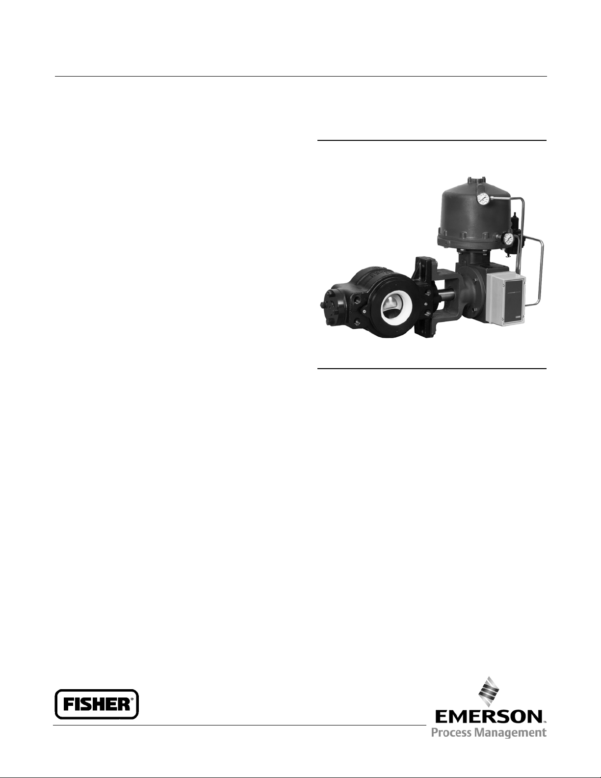
Figure 1. Fisher V250 Ball Valve with 1061 Actuator
W3698
Scope of Manual
This instruction manual provides installation, maintenance, and parts ordering information for NPS 4 through 24
Fisher V250 valves (figure 1) that mate with ASME flanges. Other instruction manuals provide information covering
the actuator and accessories.
Do not install, operate, or maintain a V250 valve without being fully trained and qualified in valve, actuator, and
accessory installation, operation, and maintenance. To avoid personal injury or property damage, it is important to
carefully read, understand, and follow all the contents of this manual, including all safety cautions and warnings. If you
have any questions about these instructions, contact your Emerson Process Management sales office before
proceeding.
Description
The V250 valve is a flangeless rotary control valve used for high pressure, throttling or on-off control of liquid or gas
applications (see figure 1). These valves operate on a rotary motion input through a splined valve-shaft/actuator-shaft
connection for use with power or manual handwheel actuators. The single seal, dual seal, and flow ring constructions
are covered in this instruction manual.
www.Fisher.com
Page 2
V250 Valve
September 2013
Table 1. Specifications
Instruction Manual
D100422X012
Valve Sizes and End Connection Styles
NPS 4 through 24 flangelessvalvesretainedbyline
Flow Characteristic
Modified equal percentage
flange bolts and designed to fit between ASME
raised-face or ring-type joint flanges. See table 2 for
valves that install between ASME flanges
Flow Direction
Forward Flow: Single seal construction is standard for
forward flow (see figure 4)
Maximum Inlet Pressure
(1)
Bidirectional Flow: Flow ring construction can be used
foreitherforwardorreverseflow
Consistent with applicable pressure-temperature
ratings listed in table 2
(see figure 5)
Bidirectional Shutoff: Dual seal construction is
required to provide shutoff for bidirectional flow (see
Maximum Allowable Shutoff Pressure Drop
(1,2,3)
Single-Seal and Dual-Seal Construction:
155 bar (2250 psi) at 38_C (100_F) and 103 bar (1500
psi) at 82_C(180_F) except where further limited by
the pressure-temperature rating of the valve body
Flow Ring Construction: Limited by the
pressure-temperature rating of the valve body
Seal Material Temperature Capability
(1)
Single-Seal and Dual-Seal Construction:
figure 12)
Shutoff Classification
Single Seal and Dual Seal Constructions: 0.0001% of
maximum valve capacity (less than 1% of Class IV,
ANSI/FCI 70-2)
Flow Ring Construction: 1% of maximum valve
capacity
Maximum Ball Rotation
90 degrees
-46 to 82_C(-50to180_F) with LCC or stainless steel
valve bodies
Flow Ring Construction with Nitrile O-Rings: -46 to
93_C(-50to200_F) with LCC steel and stainless steel
Actuator Mounting
Right-hand or left-hand mounted as viewed from the
valve body inlet for forward flow
valve bodies
Approximate Weights
Flow Ring Construction with Fluorocarbon O-Rings:
-46 to 204_C(-50to400_F) with LCC steel and
See table 3
stainless steel valve bodies
1. The pressure/temperaturelimits in this manual and any applicable standardor code limitation for valve should not be exceeded.
2. Maximum allowable shutoff pressure drops are further limited for the following constructions. The NPS 12with S20910 drive shaft is limited to 128 bar (1862 psi) from -46to 59_C
(-50 to 139_F) and to 103 bar (1490 psi) at93_C (200_F). The NPS 16 with 17-4PH steel, with 2-1/2 inch splined drive shaft is limited to 69bar (1000 psi), and withthe S20910, 2-1/2 inch
splined drive shaft is limited to 55 bar(795 psi) at all service temperatures. The NPS 24with S20910 drive shaft is limited to 92 bar (1336 psi) at all service temperatures.
3. NPS 20 CL900 and NPS 24 CL900 flow ring is limited to 1500 psi.
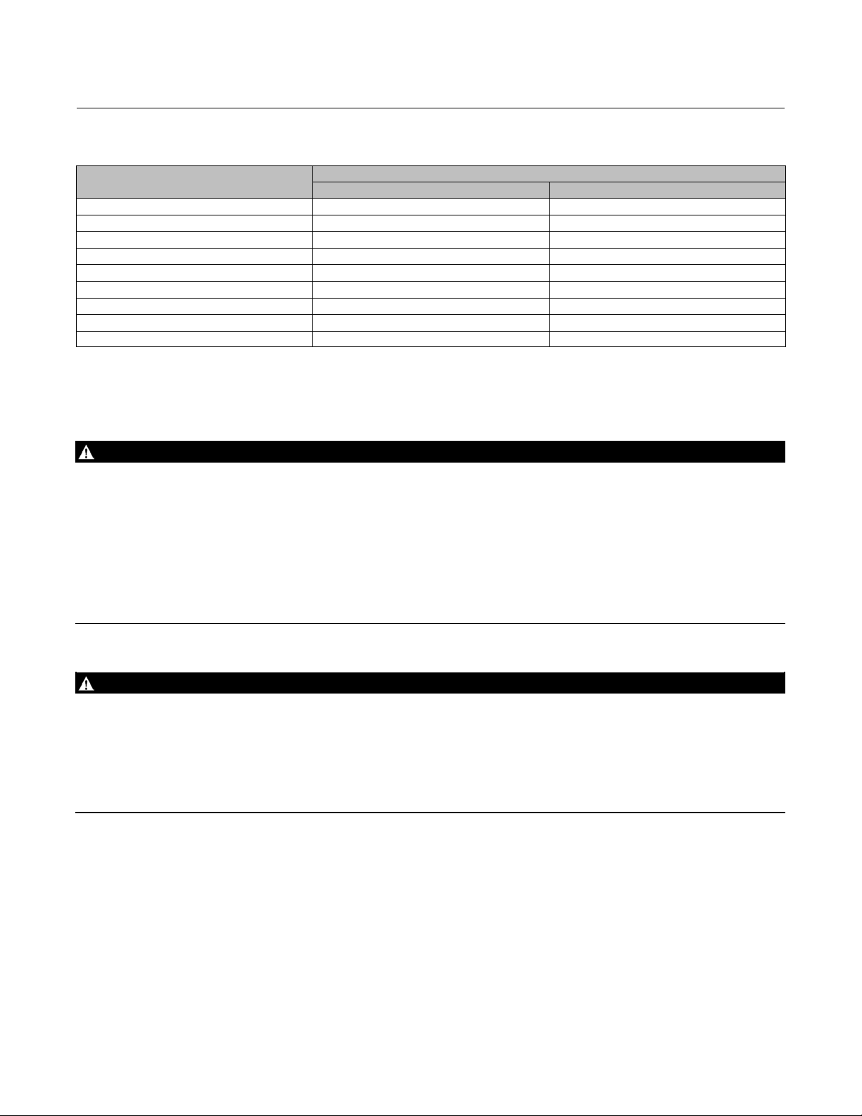
Table 2. Pressure Rating and Flange Compatibility
Valve Size, NPS Inlet Pressure Capability ASME Flange Compatibility
4
6
8
10
12
16 Consistent with CL600 (ASMEB16.34) CL600 raisedface or ring-type joint flange(ASME B16.5)
20
24
2
Consistent with CL600 or 900 (ASME B16.34) CL600 or 900 raised face or ring-type joint flange (ASME B16.5)
Consistent with CL600 or 900 (ASME B16.34) CL600 or 900 raised face or ring-type joint flange (ASME B16.5)
Page 3
Instruction Manual
D100422X012
V250 Valve
September 2013
Table 3. Approximate Weights
VALVE SIZE, NPS
4 73 160
6 132 290
8 222 490
10 345 760
12 431 950
16 771 1700
20 (CL600) 1814 4000
20 (CL900) 2045 4500
24 2404 5300
Kilograms Pounds
WEIGHT
Installation
WARNING
Always wear protective gloves, clothing, and eyewear when performing any installation operations to avoid personal
injury.
To avoid personal injury or property damage resulting from the sudden release of pressure, do n ot install the valve
assembly where service conditions could exceed the limits given on the valve and actuator nameplates. Use
pressure-relieving devices as required by accepted industry, local, state, or federal codes, and good engineering practices.
Check with your process or safety engineer for any additional measures that must be taken to protect against process
media.
If installing into an existing application, also refer to the WARNING at the beginning of the Maintenance section in this
instruction manual.
WARNING
Avoid personal injury or property damage caused by uncontrolled movement or dropping of the valve assembly.
Hoist rings are sized to lift only the valve and actuator. Do not use hoist rings to lift the valve if piping or other structures
are added.
Rig the lift to use two hoist rings and take appropriate precautions to avoid unbalanced loading which may result in sudden
swinging or movement of the assembled unit, including additional lifting and/or support methods when necessary.
Failure to utilize safe lifting practices may result in equipment damage and/or personal injury.
1. Ifthevalvewillbeplacedinstoragepriortoinstallation,protecttheflangesandkeeptheinsideofthevalvedryand
clear of foreign material.
2. Install a three-valve bypass around the control valve assembly if continuous operation will be necessary during
inspection and maintenance of the valve.
3. Inspect the valve body for damage and be certain that the valve body cavity is free of foreign material.
4. Be certain that adjacent pipelines are free of any foreign material, such as pipe scale or welding slag, that could
damage the valve body seating surfaces.
5. A V250 valve is normally shipped as part of a control valve assembly, with a power or manual handwheel actuator
mounted on the valve. If the valve and actuator have been purchased separately or if the actuator has been
3
Page 4

V250 Valve
September 2013
Instruction Manual
D100422X012
removed for maintenance, mount the actuator according to the actuator mounting procedure and adjust actuator
travel before inserting the valve into the pipeline. This allows necessary measurements to be made during the
actuator adjustment process.
The actuator can be either right-or left-hand mounted, as viewed from the valve body inlet, in any of the positions
shown in figure 10. Refer to the Actuator Mounting procedure in this manual and to the actuator instruction manual
for mounting and adjusting instructions before proceeding.
6. Before installing the valve, make sure the flow through the valve matches the flow direction arrow on the valve.
Failuretodosocandamagethesealinavalvewithasinglesealconstruction.
D For bidirectional flow, install the valve so the highest pressure flow matches the flow direction arrow on the valve.
D Install the V250 valve in any position, but the recommended orientation is in a horizontal pipeline with the shaft
positioned horizontally and the ball closing in the downward direction.
CAUTION
To avoid damage to the ball sealing surface, rotate the ball to the fully open position before installing the valve between
thepipelineflanges.
7. With the ball in the fully open position, install line flange gaskets and insert the valve between the pipeline flanges.
Use standard composition gaskets, or other flat sheet gaskets compatible with the flow media, between the valve
and the pipeline flanges. Spiral wound gaskets without compression controlling centering rings are not
recommended.
CAUTION
Uneven tightening of line bolts may cause uneven wear of the ball surface, leakage downstream or to atmosphere, or
uneven flange gasket alignment. Tighten line bolts evenly when installing the valve.
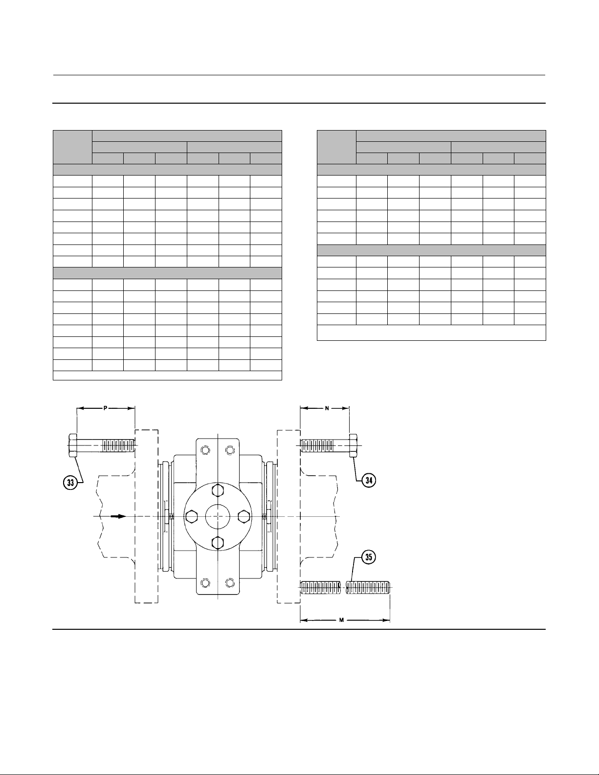
8. Centerthevalveinthelinebymakingsurethematingflangesarealigned.Securethevalveinthelinewiththecap
screws (keys 33 and 34, figures 11 and 12), line bolts (key 35, not shown), and hex nuts (key 44, not shown).
Required clearances for installation of the line bolts and cap screws are shown in figure 2. When tightening the cap
screws and line bolts, use accepted bolting procedures. Lubricate the studs or bolts and tighten the nuts in a
crisscross sequence to ensure proper alignment of the valve with the flanges.
9. For hazardous atmosphere or oxygen service valves, read the following WARNING, and perform the instruction
provided in the WARNING and provide the bonding strap assembly mentioned in Step 10 below if the valve is used
in a hazardous application.
WARNING
The V250 is not necessarily grounded to the pipeline when installed. If the process fluid or the atmosphere around the valve
is flammable, personal injury or property damage could result from an explosion caused by a discharge of static electricity
from the valve components. If the valve is installed in a hazardous area, electrically bond the drive shaft to the valve.
Note
The packing is composed of all conductive packing rings (graphite ribbon packing) to electrically bond the shaft to the valve for
hazardous area service or non-conductive PTFE packing rings. For oxygen service applications, perform the following step.
4
Page 5
Instruction Manual
D100422X012
Figure 2. Flange Bolt Lengths
V250 Valve
September 2013
VALVE
SIZE, NPS
4 --- --- 343 --- --- 343
6 118 118 413 124 124 413
8 140 137 445 143 140 451
10 159 162 527 165 165 527
12 178 152 584 178 165 584
16 197 197 660 203 203 673
20 254 254 --- 254 254 ---
24 330 330 --- 343 343 ---
4 --- --- 13.50 --- --- 14.50
6 4.63 4.63 16.25 4.88 4.88 16.25
8 5.50 5.38 17.50 5.63 5.50 17.75
10 6.25 6.38 20.75 6.50 6.50 20.75
12 7.00 6.00 23.00 7.00 6.50 23.00
16 7.75 7.75 26.00 8.00 8.00 26.50
20 10.00 10.00 --- 10.00 10.00 ---
24 13.00 13.00 --- 13.50 13.50 ---
1. These bolts may be installed from either end of the valve.
Raised Face Flanges Ring Type Joint Flanges
P N M
CL600 BOLTING DIMENSIONS
(1)
mm
Inch
P N M
VALVE
(1)
SIZE, NPS
4 124 124 375 124 130 375
6 127 127 445 127 133 445
8 152 149 483 152 156 483
10 168 171 546 168 175 546
12 184 168 610 184 191 610
(2)
20
4 4.88 4.88 14.75 4.88 5.13 14.75
6 5.00 5.00 17.50 5.00 5.25 17.50
8 6.00 5.88 19.00 6.00 6.13 19.00
10 6.63 6.75 21.5 6.63 6.88 21.50
12 7.25 6.63 24 7.25 7.50 24.00
(2)
20
1. These bolts may be installed fromeither end of the valve.
2. For NPS 20 size,only studs and nuts areused. See the M dimension.
Raised Face Flanges Ring Type Joint Flanges
P N M
--- --- 420 --- --- 420
--- --- 16.5 --- --- 16.5
CL900 BOLTING DIMENSIONS
(1)
mm
Inch
P N M
(1)
39A1060-A
A3140-1
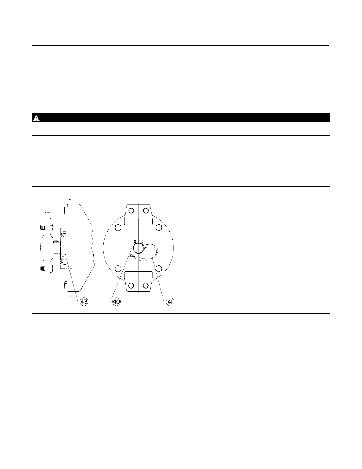
10. Attach the bonding strap assembly (key 41, figure 3) to the shaft with the clamp (key 40, figure 3), and connect
the other end of the bonding strap assembly to the valve with the machine screw (key 43, figure 3).
11. Connect pressure lines to the actuator as indicated in the actuator instruction manual. When a manual actuator is
used with a power actuator, install a bypass valve on the power actuator (if not already supplied) for use during
manual operation.
5
Page 6

V250 Valve
September 2013
Instruction Manual
D100422X012
Maintenance
Valve parts are subject to normal wear and must be inspected and replaced as necessary. The frequency of inspection
and replacement depends upon the severity of service conditions. Instructions are presented in this section for
replacing the shaft seals, the ball seal or flow ring, the drive and follower shafts, the ball and bushing, and the valve
outlet gasket.
Key number locations are shown in figure 11 for single seal and flow ring constructions, and in figure 12 for dual seal
constructions.
WARNING
Personal injury or property damage can result due to a sudden release of pressure or process fluid if the pipe plug (key 42,
figure 12) is removed while the valve is pressurized. To avoid such injury or damage, remove the pipe plug only when the
control valve is isolated from the pressure system, or provide a hand valve to control relief of internal valve pressure to
avoid personal injury or property damage.
A V250 valve with a dual seal construction contains a pipe plug port (key 42, figure 12) on the underside of the valve.
This port can be used to relieve internal valve pressure for testing seal integrity when in the pipeline.
Ifthepipeplugportistobeusedfortestingsealintegritywhenthevalveisinthepipeline,theplugshouldbereplaced
with a hand valve to allow controlled relief of valve pressure during seal leak rate testing.
WARNING
Avoid personal injury or damage to property from sudden release of pressure or uncontrolled process fluid. Before starting
disassembly:
D Do not remove the actuator from the valve while the valve is still pressurized.
D Always wear protective gloves, clothing, and eyewear when performing any maintenance operations to avoid personal
injury.
D Disconnect any operating lines providing air pressure, electric power, or a control signal to the actuator. Be sure the
actuator cannot suddenly open or close the valve.
D Use bypass valves or completely shut off the process to isolate the valve from process pressure. Relieve process pressure
on both sides of the valve. Drain the process media from either side of the valve.
D For dual seal valve constructions, remove pressure and drain the valve interior by removing the pipe plug
(key 42).
D Vent the power actuator loading pressure.
D Use lock-out procedures to be sure that the above measures stay in effect while you work on the equipment.
D The valve packing box may contain process fluids that are pressurized, even when the valve has been removed from the
pipeline. Process fluids may spray out under pressure when removing the packing hardware or packing rings, or when
loosening the packing box pipe plug.
D Check with your process or safety engineer for any additional measures that must be taken to protect against process
media.
Replacing the Follower Shaft Seal
Both the follower and drive shaft seals should be replaced at the same time. Key number locations are shown in figure
11 or 12.
6
Page 7
Instruction Manual
D100422X012
V250 Valve
September 2013
Perform this procedure if there is leakage around the follower shaft (key 7). Such leakage is an indication that the shaft
seal, which includes the seal and a backup ring, (key 16) mustbereplaced.Thefollowingproceduremaybeperformed
with the valve in the pipeline.
1. Isolatethecontrolvalvefromthelinepressure,releasepressure from both sides of valve, and drain the process
media from both sides of the valve. For dual seal valve constructions, remove pressure and drain the valve interior
cavity. Shut off and disconnect all lines from the power actuator.
WARNING
Refer to the WARNING at the beginning of the Maintenance section in this instruction manual.
2. Unscrew the hex nuts (key 8) and remove the seal carrier (key 3) and shaft seal (key 16). Inspect and clean all parts
and sealing surfaces on the seal carrier and follower shaft (key 7). Also, inspect and replace the O-ring (key 23) if
necessary.
3. Install the new backup ring and shaft seal in the seal carrier.
Figure 3. Optional Shaft-to-Body Bonding Strap Assembly
A7101
4. Align the drive pin (key 28) with the drilled hole on the inner surface of the seal carrier, replace the seal carrier, and
secure it with the hex nuts (key 8). Be careful not to damagetheshaftsealorO-ringduring replacement of the seal
carrier.
Replacing the Drive Shaft Seal
Perform this procedure if there is leakage around the drive shaft (key 6). Such leakage is an indication that the shaft
seal, which includes the seal and a backup ring, (key 16) must be replaced. This procedure may be performed with the
valveinthepipeline.However,theactuatormustberemovedfromthevalve.
7
Page 8

V250 Valve
September 2013
Note
The valve shaft's sealing surfaces are critical in obtaining a good seal. If the valve sh afts are scratched, nicked or worn, replace or
repair the valve shaft beforeinstalling new shaft seals.
Both seal rings, drive end and follower end, should be replaced at the same time.
1. Isolatethecontrolvalvefromthelinepressure,releasepressure from both sides of valve, and drain the process
media from both sides of the valve. For dual seal valve constructions, remove pressure and drain the valve interior
cavity. Shut off and disconnect all lines from the power actuator.
Instruction Manual
D100422X012
WARNING
Refer to the WARNING at the beginning of the Maintenance section in this instruction manual.
CAUTION
When removing the actuator in the following step, use a wheel puller to separate the actuator parts from the valve shaft.
Failure to do this c ould cause damage to the actuator parts and the drive shaft.
2. Remove the cap screws (key 29) from the actuator mounting yoke and, while referring to the actuator instruction
manual for assistance, remove the actuator. For oxygen service and hazardous area applications, remove the clamp
and bonding strap assembly (keys 40 and 41, figure 3).
3. Install the new backup ring and shaft seal in the seal carrier. Be sure to install the backup ring on the correct side
(see figure 4).
4. Replace the seal carrier and secure it with the hex nuts (key 8). Be careful not to damage the shaft seal or O-ring
during replacement of the seal carrier.
5. Mount the actuator to the valve while referring to the Actuator Mounting section of this instruction manual and to
the appropriate actuator instruction manual. If appropriate, install or replace the bonding strap assembly and the
clamp (key 41 and 40, figure 3).
Replacing Ball Seal or Flow Ring
Perform this procedure if the control valve is not shutting off properly (that is, leaking downstream). This procedure
does not require removing the actuator from the valve. In addition to being shown in figures 11 and 12, key numbers
areshowninfigure5fortheballsealconstructionsandinfigure6fortheflowringconstruction.
Removal
1. Isolatethecontrolvalvefromthelinepressure,releasepressure from both sides of valve, and drain the process
media from both sides of the valve. For dual seal valve constructions, remove pressure and drain the valve interior
cavity. Shut off and disconnect all lines from the power actuator.
WARNING
Refer to the WARNING at the beginning of the Maintenance section in this instruction manual.
8
Page 9

Instruction Manual
D100422X012
V250 Valve
September 2013
WARNING
The ball (key 2) closes with a shearing motion. To avoid personal injury, keep hands, tools, and other objects away from the
ball while stroking the valve.
CAUTION
Damage to the ball (key 2) may occur if the ball is not in the fully open position while the valve is being removed from the
pipeline. If necessary, pressure the actuator temporarily to retain the ball in the open position while removing the valve
from the pipeline.
2. With the ball in the fully open position, unscrew the line bolts and remove the valve from the pipeline.
3. Unscrew the cap screws (key 15, figures 11 and 12 only) and remove the seal protector ring (key 14) or the flow ring
(key 14) from the inlet end of the valve. Then remove the O-ring (key 13), the ball seal (key 11), and the shim seals
(key 10). The flow ring construction will have no ball seal. For a dual seal construction, repeat this procedure on the
other end of the valve.
4. Thoroughly clean all metal surfaces. Check all parts for damage, and replace damaged parts with new parts if
necessary.
Figure 4. Ball Seal Detail
SEAL
PROTECTOR
RING (KEY 14)
W3701-1*
SHIM SEALS
(KEY 10)
VALVE
BODY (KEY 1)
Figure 5. Flow Ring Detail
FLOW RING
(KEY 14)
O-RING
(KEY 13)
SHIM SEALS
(KEY 10)
BALL SEAL
(KEY 11)
FORWARD
FLOW
BALL
(KEY 2)
FORWARD
FLOW
W3700-1*
VALVE
BODY (KEY 1)
O-RING
(KEY 13)
BALL
(KEY 2)
9
Page 10

V250 Valve
September 2013
Figure 6. Seal & Backup Ring Assembly
SEAL
CARRIERS
BACK-UPRING
Instruction Manual
D100422X012
SPRING LOADED
SEAL RING
28B2099
INTERNAL
PRESSURE
5. Proceed to the appropriate Installation procedure to install the removed parts.
Installation of Single or Dual Ball Seal
1. Check the seal surface of the valve (key 1) for scratches that may prevent the shim seals (key 10) from sealing off
internal valve pressures.
2. Rotate the ball (key 2) to the closed position as indicated by the travel indicator scale (key 37, figures 10 and 11
only).
3. Placetheappropriatenumberofshimsealsintothevalve:
D For NPS 4 through 10 valves, insert up to 6 shim seals into the valve.
D For NPS 12 through 24 valves, insert up to 7 shim seals into the valve.
4. Inspect the sealing surface of the ball seal (key 11) for possible damage. Then place the ball seal on top of the shim
seals with any nicks or scratches facing away from the ball.
5. Add or remove the 0.25 mm (0.010 inch) thick shim seals to the valve until the ball seal firmly contacts the ball
sealing surface (i.e., without rocking) when pressed tightly against the shim seal assembly.
6. Temporarily remove the ball seal, and remove 3 shim seals.
7. Replace the ball seal, and then place the O-ring (key 13) into the valve.
8. With the ball seal centered on the ball, install the seal protector ring (key 14) and secure it to the valve with the cap
screws (key 15).
9. For dual seal c onstructions, repeat this procedure on the other end of the valve.
Installation of Flow Ring
1. Check the seal surface of the valve (key 1) for scratches that may prevent the shim seals (key 10) from sealing off
internal valve pressures.
2. Rotate the ball (key 2) to the closed position as indicated by the indicator scale (key 37, figure 11 only).
3. Placetheappropriatenumberofshimsealsintothevalve:
D For NPS 4 through 10 valves, insert 6 shim seals into the valve.
D For NPS 12 through 24 valves, insert 7 shim seals into the valve.
4. Making certain the flow ring (key 14) is centered and does not contact the ball, secure the flow ring to the valve with
the cap screws (key 15).
10
Page 11

Instruction Manual
D100422X012
V250 Valve
September 2013
5. Measuretheclearancebetweentheflowringandtheball with a wire gauge. Add or subtract shim seals until the
minimum clearance is 0.38 mm (0.015 inches) for valves used for forward flow and 0.76 mm (0.030 inches) for
reverse flow.
6. Once minimum clearance is obtained, temporarily remove the flow ring.
7. Insert the O-ring (key 13) into the valve, and secure the flow ring to the valve with the cap screws (key 15).
Installing Live-Loaded PTFE Packing
These steps refer only to the Live Loaded PTFE Packing. Key number locations are shown in figures 11, 12, and 13.
Note
The valve shaft's packing surfaces are critical in obtaining a good seal. If the valve shafts are scratched, nicked or worn, replace or
repair the valve shaft beforeinstalling the Live Loaded PTFE Packing parts.
Both seal rings, drive end and follower end, should be replaced at the same time.
1. Remove the hex nuts (key 8) from the seal carrier (key 17 on the drive shaft end and key 3 on the follower shaft
end). Remove the spacer (key 22). On NPS 4, 12, and 24 valves, the stud bolt (key 4) will need to be removed. The
drive pin (key 28) needs to be removed from the outboard end of the valve body.
2. Replace the seal carrier and spacer with the new packing box (key 17 or 3). To keep the ball properly centered inside
the valve body, the bushing spacer shims may need to be added or removed (see the Replacing Drive Shaft,
Follower Shaft, Ball, Bushings, and Valve Outlet Gasket -- Assembly section).
3. Secure the packing box with hex nuts (key 8), for NPS 6, 8, 10, 16, or 20 valves, or socket head cap screw (key 4), for
NPS 4, 12, or 24 valves. Lubricate the hex nuts or cap screws and tighten them. Be careful not to damage the O-ring
during installation of the packing box.
4. Install the packing box studs (key 100).
Note
The Belleville springs must be stacked properly and packing box parts must be assembled in the correct order, if the packing parts
are to function properly.
5. Install the packing ring, female and male adaptors, anti-extrusion rings, and packing box rings (keys 105, 106, and
107).Besuretoinstallthepackingringsintheorderandquantityshowninfigure13.
6. Install the spring pack assembly (key 103 or 104), which includes the Belleville springs, packing follower, and
O-ring. The O-ring is a non-functional part used to retain the packing springs during assembly.
7. Install the packing flange (key 102) on the shaft. Then lubricate and install the packing nuts (key 101), hand
tightening them. Apply lubricant to the stud threads, internal nut threads and contacting face of the nut. Packing
flanges with flats on the sides may need to be oriented with the mounting bracket so the flange will fit between the
legs of the bracket.
8. To obtain optimum maximum benefit from the packing system, tighten the packing flange nuts and compress the
Belleville springs to their Target Load. The Belleville springs are designed to provide optimum performance at their
Target Load, 85% of their maximum deflection/compression.
To obtain the Target Load compression, tighten the packing flange nuts alternately and evenly, keeping the packing
flange parallel with the valve flange, until the Belleville springs are compressed 100%. Then loosen each packing flange
nut one half turn (180_ of rotation).
11
Page 12

V250 Valve
September 2013
Instruction Manual
D100422X012
Replacing Drive Shaft, Follower Shaft, Ball, Bushings, and Valve Outlet
Gasket
Thisprocedureistobeperformedtoreplacethevalveball,thedriveshaft,andthefollowershaft,iftheballdoesnot
rotate in response to rotation of the actuator end of the drive shaft, or if there is leakage around the outlet gasket.
Disassembly
CAUTION
When removing the actuator from the valve, do not use a hammer or similar tool to drive the lever off the valve shaft.
Driving the actuator lever off the valve shaft could move the ball (key 2) from the centered position, causing damage to the
ball, the ball seal (key 11), and the valve (key 1).
Use care when removing the actuator lever and, if necessary, use a wheel puller to remove the lever or actuator from the
valve shaft. It is okay to tap the wheel puller screw lightly to loosen the lever or actuator, but hitting the screw with
excessive force could also damage the valve.
1. Remove the cap screws (key 29) from the actuator mounting yoke and, while referring to the actuator instruction
manual for assistance, remove the actuator. If appropriate, remove the clamp and bonding strap assembly (key 40
and 41, figure 3).
2. Remove either the seal protector ring (key 14) o r the flow ring (key 14) from the inlet end of the valve assembly by
following steps 1, 2, and 3 of the Replacing Ball Seal or Flow Ring section. For dual seal constructions, note that this
procedure should be repeated on the outlet end of the valve.
3. Proceed as appropriate:
D For single seal constructions and flow ring constructions (figure 11 only), remove the cap screws (key 15).
D Then, remove the valve outlet (key 5) and gasket (key 12).
Note
Perform the following step with the inlet end of the valve assembly facing upward and with the ball (key 2) in the fully open
position.
4. Remove the hex nuts (key 8) from the follower shaft (key 7) side of the valve. Then remove the seal carrier (key 3).
Inspect and replace the seal (key 16) and O-ring (key 23) if necessary.
Note
During the following step, it may be necessary to apply heat to the retainer screw (key 32) to disengage the thread locking
adhesive (high strength) (key 30) that holds the retainer screw in place.
5. Remove the retainer screw (key 32).
6. Using a soft-faced hammer to prevent damaging the end of the follower shaft (key 7), drive the follower shaft into
theflowboreoftheballjustenoughsothatthesplitring (key 31) can be removed. Then remove the split ring.
12
Page 13

Instruction Manual
D100422X012
V250 Valve
September 2013
Table 4. Shaft Retainer and Retainer Screw Torques
VALVE SIZE,
NPS
4 136 27 100 20
6 759 27 560 20
8 1390 41 1025 30
10 1760 41 1295 30
12 2390 68 1760 50
16 3830 68 2825 50
20 6660 68 4910 50
24 12300 68 9075 50
Shaft Retainer
(Key 25)
NSm LbfSFt
Retainer Screw
(Key 32)
Shaft Retainer
(Key 25)
Retainer Screw
(Key 32)
7. Remove the follower shaft (key 7), the spacer (key 22), the bushing spacer shims (key 18), the bushing (key 20), t he
thrust washer (key 19), and the thrust spacer (key 21) from the valve.
8. Insert a ball support post (see figure 7) into the follower shaft (key 7) bore of the valve. Use of the ball support post
will ensure that the ball sealing surfaces will not get damaged as the shaft retainer (key 25) is being removed.
Position the ball support post so that the ball will be supported firmly inside the valve body cavity during the
performance of the next three steps.
Note
During the following step, it may be necessary to apply heat to the shaft retainer (key 25) to disengage the thread locking adhesive
(high strength) (key 30) that holds the shaft retainer in place.
9. Remove the shaft retainer (key 25) and the washer (key 24).
10. Remove the hex nuts (key 8) from the drive shaft (key 6) side of the valve. Then remove the seal carrier (key 17).
Inspect and replace the seal (key 16) and O-Ring (key 23) if necessary.
11. With the ball firmly supported, remove the drive shaft (key 6) and attached parts out of the valve. Attached parts
will include the spacer (key 22), the bushing spacer shims (key 18), the bushing (key 20), the thrust washer (key 19),
and the thrust spacer (key 21).
12. While maintaining firm support of the ball (key 2), proceed as follows:
D First, remove the ball support post through the follower shaft bore of the valve.
D Then, while being careful not to damage the sealing surfaces of the ball, remove the ball through the outlet end of
the valve.
13. Inspect and, if necessary, replace all parts. Then, proceed to the assembly procedure below.
13
Page 14

V250 Valve
September 2013
Figure 7. Ball Support Post Dimensions
Instruction Manual
D100422X012
VALVE SIZE
NPS
4
6
8
10
12
16
20
24
4
6
8
10
12
16
20
24
1. Tolerances for the Aand C dimensions are indicated by showing maximum and minimum dimensions.
2. Numbers of holes in port.
(1)
A
41.02
40.77 31.37 9.04
63.25
62.99 50.42 13.89
75.95
75.69 63.12 17.07
85.47
85.22 69.47 17.07
91.82
91.57 75.82 20.35
126.7
126.4 101.0 26.70
152.1
151.8 126.4 26.70
180.6
180.2 151.8 33.05
1.615
1.605 1.235 0.356
2.490
2.480 1.985 0.547
2.990
2.980 2.485 0.672
3.365
3.355 2.735 0.672
3.615
3.605 2.985 0.801
4.990
4.975 3.975 1.051
5.990
5.975 4.975 1.051
7.110
7.095 5.975 1.301
B C
23.83
41.28
50.80
53.98
60.33
82.55
104.8
127.0
0.938
1.625
2.000
2.125
2.375
3.250
4.125
5.000
(1)
31.62
50.67
63.37
69.72
76.07
101.3
126.7
152.1
1.245
1.995
2.495
2.745
2.995
3.990
4.990
5.990
D E F
mm
146.1 22.23 4
165.1 25.40 4
215.9 34.93 4
215.9 44.45 4
228.6 50.80 4
292.1 66.68 4
336.6 85.73 4
368.3 92.08 4
Inches
5.750 0.875 4
6.500 1.000 4
8.500 1.375 4
8.500 1.750 4
9.000 2.000 4
11.500 2.625 4
13.250 3.375 4
14.500 3.625 4
(2)
(1)
G
8.69
13.39
16.56
16.56
19.74
26.04
26.04
32.39
0.342
0.527
0.652
0.652
0.777
1.025
1.025
1.275
H J K
30.18 7.95 46.05
46.02 11.13 68.28
55.58 12.70 85.73
55.58 15.88 87.33
65.07 14.30 100.03
93.68 19.05 138.13
93.68 23.83 163.53
136.53 25.40 195.28
1.188 0.313 1.813
1.812 0.438 2.688
2.188 0.500 3.375
2.188 0.625 3.438
2.562 0.563 3.938
3.688 0.750 5.438
3.688 0.938 6.438
5.375 1.000 7.688
14
39A1059-B
A3141-1
Page 15

Instruction Manual
D100422X012
Figure 8. Index Marks on Drive Shaft and Ball
V250 Valve
September 2013
INDEX MARK ON POLYGON COUPLING
END OF DRIVE SHAFT (KEY 6)
79BA08073-A
B1793
INDEX MARK ON HUB
OF BALL (KEY 2)
Assembly
1. Positiontheball(key2)sothatitisfirmlysupportedinsidethevalve(key1).Insertaballsupportpost(seefigure7)
into the follower shaft (key 7) bore of the valve. Position the ball support post so that the ball will be supported
firmly inside the valve body cavity while performing steps 2 through 5.
CAUTION
Damage to the valve assembly and downstream equipment could occur if the shaft retainer (key 25) should become
disengaged from the drive shaft (key 6) during operation of a V250 control valve assembly. To prevent such damage, make
sure that the internal threads in the Polygon coupling end of the drive shaft and the external threads of the shaft retainer
are cleaned thoroughly before applying thread locking adhesive (high strength) (key 30) as described in step 5 of this
assembly procedure.
2. Insert the drive shaft (key 6) into the drive shaft side of the valve and ball assembly. When inserting the drive shaft,
make sure that the index mark on the Polygon coupling end of the drive shaft is aligned with the index mark on the
hub of the ball. Refer to figure 8 for the location of these index marks.
3. Install the thrust spacer (key 21) into the drive shaft side of the valve and position it so that it is in contact with the
ball hub. Then, install the thrust washer (key 19) and the bushing (key 20).
4. Insert the washer (key 24) into the ball. Lubricate the exposed surface of the washer with a good quality grease or
lubricant.
CAUTION
Improper tightening of the shaft retainer (key 25) could allow the shaft retainer to become disengaged from the drive shaft
(key 6) during operation of a V250 control valve assembly. This could cause damage to the valve assembly and downstream
15
Page 16

V250 Valve
September 2013
equipment. To prevent such damage, make sure that the shaft retainer is tightened to the appropriate torque value listed
in table 4.
Instruction Manual
D100422X012
5. Apply thread locking adhesive (high strength) (key 30) to the threads of the shaft retainer (key 25). Then, install the
shaft retainer into the inside end of the driveshaft.Tightentheshaftretainertothetorquevaluelistedintable4.
CAUTION
Damage to the valve assembly and downstream equipment could occur if the retainer screw (key 32) should become
disengaged from the follower shaft (key 7) during operation of a V250 control valve assembly. To prevent such damage,
make sure that the internal threads in the inside end of the follower shaft and the external threads of the retainer screw are
cleaned thoroughly before applying thread locking adhesive (high strength) (key 30) as described in step 8 of this assembly
procedure.
6. While maintaining firm support of the ball (key 2), remove the ball support post through the follower shaft bore of
the valve. Then install the follower shaft into the valve. When installing the follower shaft, make sure that the drilled
hole containing the two pins (key 9) is aligned with the two notches machined on the inside surface of the ball hub.
7. Temporarily position the follower shaft so that it protrudes slightly into the flow bore of the ball. Place the split ring
(key 31) on the end of the follower shaft. Then, return the follower shaft to its original position.
CAUTION
Improper tightening of the retainer screw (key 32) could allow the retainer screw to become disengaged from the follower
shaft (key 7) during operation of a V250 control valve assembly. This could cause damage to the valve assembly and
downstream equipment. To prevent such damage, make sure that the retainer screw is tightened to the appropriate
torque value listed in table 4.
8. Apply thread locking adhesive (high strength) (key 30) to the threads of the retainer screw. Then, install the retainer
screw into the inside end of the follower shaft until it is at least flush with the end surface of the follower shaft. Make
sure that the drilled hole containing the two pins (key 9) is still aligned with the two notches machined on the inside
surface of the ball hub. Tighten the retainer screw to the torque value listed in table 4.
9. Install the thrust spacer (key 21) into the follower shaft side of the valve and position it so that it is in contact with
the ball hub. Then, in stall the thrust washer (key 19) and the bushing (key 20).
10. Center the ball inside the valve along the axis of both the drive shaft and the follower shaft. The maximum
deviation in measurement between the valve and ball from one side to the other should be no more than 0.005
inches (0.127 mm) as shown in figure 9.
11. In order to maintain proper centering of the ball inside the valve, the bushing spacer shims (key 18) must be
installed in the following manner.
D For the drive shaft side of the valve, i nstall several bushing spacer shims around the drive shaft and into the valve.
Then, temporarily install the spacer (key 22) and the seal carrier (key 17). Repeat this process, but add only one
more bushing spacer shim into the valve each time, until contact between the seal carrier and the valve is broken.
Then, remove one bushing spacer s him and secure the spacer and seal carrier to the valve with the hex n uts (key 8).
Be careful not to damage the seal (key 16) or O-ring (key 23) during replacement of the seal carrier.
16
Page 17

Instruction Manual
D100422X012
Figure 9. Proper Alignment for Centering the Ball
AB
V250 Valve
September 2013
FG51287-A
A3142
AXIS OF DRIVE SHAFT (KEY 6) AND FOLLOWER SHAFT (KEY 7)
A - B = 0.127 mm (0.005 INCHES) MAX
D Forthefollowershaftsideofthevalve,installseveralbushing spacer shims around the follower shaft and into the
valve. Then, temporarily install the spacer (key 22) and the seal carrier (key 3). Repeat this process, but add only one
more bushing spacer shim into the valve each time, until contact between the seal carrier and the valve is broken.
Then, remove one bushing spacer s him and secure the spacer and seal carrier to the valve with the hex n uts (key 8).
Be careful not to damage the seal (key 16) or O-ring (key 23) during replacement of the seal carrier.
12. Install the seal protector ring (key 14, figure 5) or the flow ring (key 14, figure 6) and all remaining parts by
following the appropriate procedures presented in the Ball Seal and Flow Ring Maintenance section.
13. For NPS 20 CL900 and NPS 24 CL900 valves, lifting hoist rings are provided. If the safety hoist rings were removed,
replacethemandtorquethemto312NSm (230 lbfSft).
14. Mount the actuator to the valve while referring to the actuator mounting section of this instruction manual and to
the appropriate actuator instruction manual. If appropriate, replace the bonding strap assembly and the clamp (key
41 and 40, figure 4).
15. Install the valve into the pipeline by referring to the Installation section of this instruction manual.
17
Page 18

V250 Valve
September 2013
Figure 10. Index Marks for Actuator Mounting
Instruction Manual
D100422X012
48A8905-B
48A8827-A
18
NOTES:
1. ARROW ON LEVER INDICATESDIRECTION OF ACTUATOR THRUST TO CLOSE VALVE.
2. PDTC–PUSH DOWN TO CLOSE;PDTO–PUSH DOWN TO OPEN.
3. THE NPS 16 TO 24 V250 MOUNTING CHART APPLIESTO VALVES USED WITH 1069 ACTUATORS ONLY.
Page 19

Instruction Manual
D100422X012
V250 Valve
September 2013
Actuator Mounting
Use the appropriate actuator instruction manual and figure 10 of this instruction manual when changing actuator
styles and positions. The actuator may be either right- or left-hand mounted. Figure 10 shows the correct lever/shaft
orientation for both left-hand mounting and right-hand mounting configurations.
Travel Adjustment
Actuator travel adjustment can be performed with the valve either in or out of the pipeline. Key numbers referenced in
the following procedures are shown in figure 11 for single seal and flow ring constructions and in figure 12 for dual seal
constructions.
D For valve assemblies in the pipeline:
1. Rotate the ball (key 2) to either the open or closed position as indicated by the travel indicator scale (key 37) on the
outboard end of the valve.
2. Adjust the actuator as described in the appropriate actuator instruction manual until the arrow stamped on the end
of the follower shaft (key 7) is fully aligned with the open or closed position on he travel indicator scale.
D For valve assemblies out of the pipeline, proceed as follows:
1. Rotate the ball to the fully open position. The fully open position is achieved when the inside surface of the ball bore
(key 2) is completely square with the line flange gasket surface of the seal protector ring (key 14) or flow ring (key
14).
2. Adjust the actuator as described in the appropriate actuator instruction manual until the inside surface of the ball
bore is at right angles to the line flange gasket surface of the seal protector ring or flow ring.
3. Adjust the travel indicator scale (key 37) until the arrow stamped on the end of the follower shaft (key 7) is fully
aligned with the open position.
Parts Ordering
When corresponding with your Emerson Process Management sales office about this equipment, always mention the
valve serial number. When ordering replacement parts, also specify the complete 11-character part number of each
part required from the following parts list.
WARNING
Use only genuine Fisher replacement parts. Components that are not supplied by Emerson Process Management should
not, under any circumstances, be used in any Fisher valve, because they may void your warranty, might adversely affect the
performance of the valve, and could cause personal injury and property damage.
19
Page 20

V250 Valve
September 2013
Figure 11. Fisher V250 Valve Assembly with Single Seal Construction
Instruction Manual
D100422X012
NOTE:
1. KEY NUMBERS 35, 38, 39, AND 44 ARE NOT SHOWN.
APPLY AN ADHESIVE
48A2246-J
20
Page 21

Instruction Manual
D100422X012
Figure 12. Fisher V250 Valve Assembly with Dual Seal Construction
V250 Valve
September 2013
NOTE:
1. KEY NUMBERS 35, 38, 39, AND 44 ARE NOT SHOWN.
APPLY AN ADHESIVE
48A2248-J
21
Page 22

V250 Valve
September 2013
Figure 13. Live Loaded Packing Assembly
Instruction Manual
D100422X012
NPS 6, 10,12, & 16(4X3-1/2” SHAFT)
NPS 4, 12 & 24
37B3095-F
PACKING BOX BOLTING
Parts Kits
Live-Loaded PTFE Packing kits
VALVE SIZE, NPS KITPARTNUMBER
4 37B3095X142
6 37B3095X102
8 37B3095X062
10 37B3095X042
12 37B3095X182
16 37B3095X132
20 37B3095X082
24 37B3095X162
NPS 4, 8, 20, 24, & 16 (4x2-1/2” SHAFT)
PACKING RINGS, KEY 105B
Part kits include keys 10, 11, 12, 13, 16, 18, 19, and
23. See following table.
VALVE SIZE,
KEY
NUMBER
Key 10 Shim seal 2 4 2
Key 11 Ball seal 1 2 ---
Key 12 Gasket 1 1 1
Key 13 O-ring 1 2 1
Key 16 Seal ring 2 2 2
Key 18
Key 19 Washer 2 2 2
Key 23 O-ring 2 2 2
NPS 6, 12, 24,
20 CL600, &
16 (4X3-1/2” SHAFT)
NPS 4, 8, 10,
20 CL900, &
16 (4X2-1/2” SHAFT)
BELLEVILLE SPRING STACK
KITPARTNUMBER
NPS
4 RV250X00412 RV250X00422 RV250X00432
6 RV250X00612 RV250X00622 RV250X00632
8 RV250X00812 RV250X00822 RV250X00832
10 RV250X01012 RV250X01022 RV250X01032
12 RV250X01212 RV250X01222 RV250X01232
16 RV250X01612 RV250X01622 RV250X01632
20 RV250X02012 RV250X02022 RV250X02032
24 RV250X02412 RV250X02422 RV250X02432
Single Seal Dual Seal Flow Ring
DESCRIPTION
Bushing spacer
shim
QUANTITY IN KIT
Single Seal Dual Seal Flow Ring
4 4 4
22
Page 23

Instruction Manual
D100422X012
V250 Valve
September 2013
Parts List
Note
Except where indicated, sizes shown are valve sizes.
Part number s are shown for recommended spares only. For part
numbers not shown, contact your Emerson Process Management sales
office.
Key Description Part Number
1ValveBody
If youneed a valve body as a replacement part, order byvalve
size and trim diameter, serial number, and desired material.
2Ball
3 Outboard Seal Carrier
4StudBolt
5 Valve Outlet (for single ball seal & flow ring constructions only,
none req'd for dual ball seal construction)
6 Drive Shaft
7 Follower Shaft
8HexNut
9Pin
10* Shim Seal, S31600 SST (a maximum
of 14 req'd for any construction)
NPS 4 18A2529X012
NPS 6 18A2554X012
NPS 8 18A2585X012
NPS 10 18A2618X012
NPS 12 18A2646X012
NPS 16 18A4577X012
NPS 20 18A4610X012
NPS 24 18A4644X012
11* Ball Seal, POM (polyoxymethylene) (1 req'd for single ball seal
construction; 2 req'd for dual ball seal construction;
none req'd for flow ring construction)
NPS 4 18A2528X012
NPS 6 18A2553X012
NPS 8 18A2584X012
NPS 10 18A2617X012
NPS 12 1R834706372
NPS 16 18A4576X012
NPS 20 18A4609X012
NPS 24 18A4643X012
12* Gasket, PTFE
NPS 4 18A2530X012
NPS 6 18A2555X012
NPS 8 18A2586X012
NPS 10 18A2619X012
NPS 12 18A2647X012
NPS 16 18A4578X012
NPS 20 18A4611X012
NPS 24 18A5004X012
13* O-Ring (1 req'd for single ball seal & flow ring
constructions; 2 req'd for dual ball seal construction)
Nitrile
NPS 4 19A1334X012
NPS 6 18A2556X012
NPS 8 1P5585X0022
NPS 10 1V2826X0022
NPS 12 18A2648X012
Key Description Part Number
NPS 16 18A4579X012
NPS 20 13A7928X012
NPS 24 18A5005X012
Fluorocarbon
NPS 4 19A1334X022
NPS 6 18A2556X032
NPS 8 1P5585X0032
NPS 10 1V282606382
NPS 12 18A2648X022
NPS 16 18A4579X022
NPS 20 13A7928X022
NPS 24 18A5005X022
14 Seal Protector Ring
15 Cap Screw
16* Shaft Seal Kit (1 req'd) (includes 2 seals and backup rings)
NPS 4 28B2099X022
NPS 6 28B2099X032
NPS 8 28B2099X042
NPS 10 28B2099X052
NPS 12 28B2099X062
NPS 16 28B2099X072
NPS 20 28B2099X082
NPS 24 28B2099X092
17 Seal Carrier
18* BushingSpacer Shim, S31600 SST
NPS 4 (20 req'd) 18A2525X012
NPS 6 (20 req'd) 18A2550X012
NPS 8 (20 req'd) 18A2581X012
NPS 10 (20 req'd) 18A2614X012
NPS 12 (22 req'd) 18A2643X012
NPS 16 (22 req'd) 18A4574X012
NPS 20 (22 req'd) 18A4607X012
NPS 24 (22 req'd) 18A4641X012
19* Thrust Washer, Graphite filled PTFE (2 req'd)
NPS 4 18A2522X012
NPS 6 18A2547X012
NPS 8 18A2588X012
NPS 10 18A2611X012
NPS 12 18A2640X012
NPS 16 18A4571X012
NPS 20 18A4604X012
NPS 24 18A4638X012
20* Bushing(2 req'd)
S41600 [416 SST/PTFE use
w/ S17400 (17-4PH SST) shafts]
NPS 4 18A2520X042
NPS 6 18A2545X042
NPS 8 28A2577X042
NPS 10 18A2609X042
NPS 12 28A2638X042
NPS 16 28A4569X042
NPS 20 28A4602X042
NPS 24 28A4636X042
S31600 SST/PTFE
(use w/ S20910 stainless steel shafts)
NPS 4 18A2520X052
NPS 6 18A2545X052
NPS 8 28A2577X052
NPS 10 18A2609X052
NPS 12 28A2638X052
NPS 16 28A4569X052
NPS 20 28A4602X052
NPS 24 28A4636X052
21 Thrust Spacer
*Recommended spare parts
23
Page 24

V250 Valve
September 2013
Instruction Manual
D100422X012
Key Description Part Number
22 Spacer
23* O-Ring(2 req'd)
Nitrile
NPS 4 1K136506992
NPS 6 1D4392X0032
NPS 8 1K181006992
NPS 10 1D7357X0022
NPS 12 1P7427X0032
NPS 16 1R321406992
NPS 20 1D4446X0032
NPS 24 1F1727X0042
Fluorocarbon
NPS 4 1K1365X0052
NPS 6 1D4392X0022
NPS 8 1K1810X0022
NPS 10 1D7357X0012
NPS 12 1P7427X0022
NPS 16 1R3214X0012
NPS 20 1D4446X0012
NPS 24 1F1727X0012
24 Washer
25 Shaft Retainer
26 Adaptor Ring
27 Cap Screw
28 Drive Pin
29 Cap Screw
30 Thread Locking Adhesive (High Strength)
(not furnished with valve)
31 Split Ring
32 Retainer Screw
33 Cap Screw
34 Cap Screw
35 Line Bolt (see figure 2)
36 Drive Screw
37 Indicator Scale
38 Nameplate, SST (use when actuator isnot furnished; not shown)
40 Clamp, SST (see figure 3)
41 Bonding Strap Assembly, SST (see figure3)
42 Pipe Plug
43 Machine Screw, steel (see figure 3)
44 Hex Nut
100 Packing Flange Stud
101 Hex Nut
102 Packing Flange
103 Spring Packing, Drive End
104 Spring Packing, Follower End
Key Description Part Number
105A* Packing Female Adaptor,PTFE (2 req'd)
NPS 4 12B7451X012
NPS 6 14B3186X012
NPS 8 14B3059X012
NPS 10 17B4619X012
NPS 12 14B5653X012
NPS 16 17B3103X012
NPS 20 14B5805X012
NPS 24 17B7855X012
105B* Packing Ring, PTFE
NPS 4 12B7452X012
NPS 6 14B3185X012
NPS 8 14B3058X012
NPS 10 17B4620X012
NPS 12 14B5654X012
NPS 16 17B3104X012
NPS 20 14B5806X012
NPS 24 17B7856X012
105C* Packing Male Adaptor, PTFE (2 req'd)
NPS 4 12B7453X012
NPS 6 14B3184X012
NPS 8 14B3057X012
NPS 10 17B4621X012
NPS 12 14B5655X012
NPS 16 17B3105X012
NPS 20 14B5807X012
NPS 24 17B7857X012
106* Anti-Extrusion Ring,
Carbon/Graphite filled PEEK (4 req'd)
NPS 4 12B7454X012
NPS 6 14B3183X012
NPS 8 14B3056X012
NPS 10 17B4618X012
NPS 12 14B5656X012
NPS 16 17B3107X012
NPS 20 14B5808X012
NPS 24 17B7858X012
107* Packing Box Ring (2 req'd)
NPS 4 17B7992X012
NPS 6 17B5610X012
NPS 8 17B4902X012
NPS 10 17B4603X012
NPS 12 17B3100X012
NPS 16 17B6646X012
NPS 20 17B4922X012
NPS 24 17B8072X012
*Recommended spare parts
Neither Emerson, Emerson Process Management, nor any of their affiliated entities assumes responsibility for the selection,use or maintenance
of any product. Responsibilityfor proper selection, use, and maintenance of any productremains solely with the purchaser and end user.
Fisher is a mark owned by one of the companiesin the Emerson Process Management business unit of EmersonElectric Co. Emerson Process Management,
Emerson, and the Emerson logo are trademarks and service marks of Emerson Electric Co. All othermarks are the property of their respective owners.
The contents of this publication are presented for informational purposes only, and while every effort has been made to ensure their accuracy, they arenot
to be construed as warranties or guarantees, express or implied, regarding the products or services described herein or their use or applicability. All sales are
governed by our terms and conditions, which are available upon request. We reserve the rightto modify or improve the designs or specifications of such
products at any time without notice.
Emerson Process Management
Marshalltown, Iowa 50158 USA
Sorocaba, 18087 Brazil
Chatham, Kent ME4 4QZ UK
Dubai, United Arab Emirates
Singapore 128461 Singapore
www.Fisher.com
24
E 1983, 2013 Fisher Controls International LLC. All rights reserved.
 Loading...