

Page 1
Product Bulletin
51.3:V250
November 2007
Design V250 Rotary Control Valve
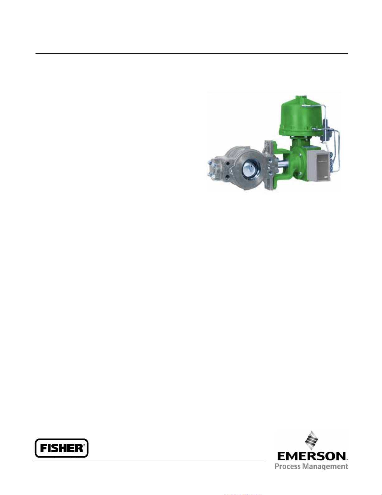
The Design V250 Hi-Ball rotary control valve
(figure 1) is designed for heavy-duty throttling and
on-off applications. Depending on size, this valve
installs between two CL600 or CL900 pipeline
flanges. The Design V250 valve is available with a
single ball seal, flow ring, or dual-seal construction.
Single-seal constructions are used in tight shutoff
applications; the flow ring construction can satisfy
higher temperature requirements. The dual-seal
construction, with a seal in the inlet and outlet
openings, is used in bidirectional flow-shutoff
applications. The Design V250 Hi-Ball valve is
typically used for throttling and controlled flow
applications in gas transmission lines, gas
distribution, or liquid pipelines.
V250 Valve
Note
Neither Emerson, Emerson Process
Management, nor any of their affiliated
entities assumes responsibility for the
selection, use and maintenance of any
product. Responsibility for the
selection, use, and maintenance of any
product remains with the purchaser
and end-user.
Features
High Pressure Drop Capabilities—Depending
on the construction, a Design V250 valve is capable
of a maximum static pressure differential of 103 bar
(1500 psi) at 82°C (180°F) for CL600, and 155 bar
(2250 psi) for CL900 constructions at 38°C (100°F)
for LCC steel and CF8M (316 stainless steel).
Efficient Operation—Tapered-polygon
ball-to-shaft connection (see figure 5) and clamped
splined actuator connection (see figure 6) remove
lost motion or deadband from the drive train for
throttling control applications.
W4177 / IL
Figure 1. Design V250 Valve with Type 1061 Actuator
Tight Shutoff—Shutoff with the Design V250
ball seal is 0.0001 percent of maximum capacity.
Greater Capacities—Design V250 ball valve
construction offers greater capacities than
conventional globe valves for both compressible and
incompressible fluids.
Sour Service Capability—Materials are
available for applications handling sour service.
These materials comply with the requirements of
NACE MR0175-2002.
Long Service Life—Pressure-balanced drive
shaft design with PTFE-lined bearings and
pressure-assisted shaft sealing arrangement
provides for a long life of reliable service.
Minimum Maintenance—Two-piece ball and
shaft assembly allows for complete trim overhaul;
parts replacement is kept to a minimum.
Excellent Flow Control—Reduced ball port
design provides a modified equal percentage flow
characteristic and an excellent response
characteristic.
www.Fisher.com
Excellent Environmental Capabilities—The
optional live loaded packing system is designed with
very smooth shaft surfaces and live loading to
provide excellent sealing.
D100053X012
Page 2

V250 Valve
Specifications
Product Bulletin
51.3:V250
November 2007
Available Configuration
Flangeless ball valve assembly with
flow ring, or dual ball seal
seal,
single ball
Valve Body Sizes and End Connection Styles
NPS 4 through 12 flangeless valves retained by
line flange bolts and designed to fit between
CL600 or CL900
raised-face or ring-type
joint flanges (ASME B16.5)
NPS 16 through 24 flangeless valves retained by
line flange bolts and designed to fit between
CL600
raised-face or ring-type joint flanges
(ASME B16.5)
Maximum Inlet Pressure
(1)
NPS 4 through 12 consistent with CL600 or
CL900 (ASME B16.34)
NPS 16 through 24 consistent with CL600
(ASME B16.34)
Maximum Allowable Shutoff Pressure Drop
(1,2)
Single-Seal and Dual-Seal Construction: See
figure 3.
Flow Ring Construction: Limited by the
pressure-temperature rating of the valve body
Flow Characteristic
Modified equal percentage
Flow Direction
Single Seal Construction: Forward-flow only
(see figure 4)
Flow Ring Construction: Forward- or
reverse-flow (see figure 4)
Dual Seal Construction: Required to provide
shutoff for bi-directional flow
Flow Coefficients
See the section titled Coefficients in this bulletin,
or see Catalog 12
Noise Levels
Shutoff Classification
Single-Seal and Dual-Seal Constructions:
0.0001% of maximum valve capacity (less than
1% of Class IV, ANSI/FCI 70-2 and IEC 60534-4)
Flow Ring Construction: 1% of maximum valve
capacity
Construction Materials
See table 1
Seal Material Temperature Capability
(1)
Single-Seal and Dual-Seal Construction:
–46 to 82°C (–50 to 180°F) for LCC steel and
CF8M [316 stainless steel (SST)] valve bodies
Flow Ring with Nitrile O-Rings:
(
–50 to 200°F) for LCC steel and CF8M valve
–46 to 93°C
bodies
Flow Ring with Fluorocarbon O-Rings:
to 204°C (
–50 to 400°F) for LCC steel and CF8M
–46
valve bodies
See Catalog 12 for sound pressure level
prediction
Maximum Ball Rotation
90 degrees
Actuator Mounting
Right-hand or left-hand mounted as viewed
from the valve inlet for forward-flow
Shaft and Bore Diameters
See figure 8
(continued)
2
Page 3
Product Bulletin
51.3:V250
November 2007
Specifications (continued)
V250 Valve
Approximate Weights
See table 2
Options
Line flange bolts, Sour service trim
(3)
,
seal configuration for bi-directional shutoff (this
configuration incorporates a tapped and plugged
connection which can be used in a double block
and bleed system to test seal integrity),
Live
Loaded PTFE Packing
Buried service actuator adaptation, and Dual
1. The pressure or temperature limits in this bulletin and any applicable standard or code limitations should not be exceeded.
2. The maximum allowable shutoff pressure drops are further limited for the following constructions. The NPS 12 with S20910 drive shaft is limited to 128 bar (1862 psi) from –46 to 59°C (–50
to 139°F) and to 103 bar (1490 psi) at 93°C (200°F). The NPS 16 with 17-4PH steel, with 2-1/2 inch splined driveshaft is limited to 1000 psi (69 bar), and with the S20910, 2-1/2 inch splined
drive shaft is limited to 55 bar (795 psi) at all service temperatures. The NPS 24 with S20910 drive shaft is limited to 92 bar (1336 psi) at all service temperatures.
3. See table 1 for sour service trim materials.
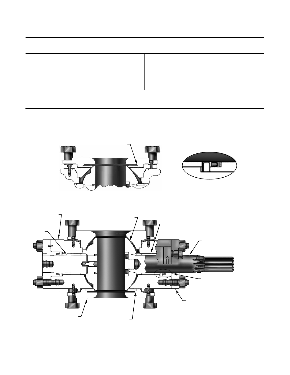
OUTLET
BALL
SEAL
W7169-1 / IL
W7170-1 / IL
OUTLET SIDE OF VALVE BODY FOR
OPTIONAL DUAL SEAL CONSTRUCTION
VIEW A
SEAL DETAIL
FOLLOWER
SHAFT
W7169-1 / IL
VALVE
BODY
SEAL PROTECTOR
RING OR FLOW RING
BALL
MAIN SHAFT
BEARING
VALVE
INLET
INLET
BALL
SEAL
Figure 2. Sectional View of Design V250 Valve
SEAL
CARRIER
DRIVE SHAFT
SEE VIEW A
3
Page 4

V250 Valve
y,
Valve Body
Body Outlet, and Seal Protector
Ball
O Rings
Seal Carrier Stud Bolts
Seal Carrier Hex Nuts
(2)
(2)
VALVE SIZE
Table 1. Construction Materials
Part Construction Material
Valve Bod
Body Outlet, and Seal Protector
Ring or Flow Ring
Drive Shaft, Follower Shaft,
and Shaft Retainer
Ball
Ball Seal All Trims POM (polyoxymethylene)
Bearings All Trims PTFE/Composition-lined S31600
O-Rings
Shaft Seal
Seal Carrier All Trims S31600 SST
Seal Carrier Stud Bolts
Seal Carrier Hex Nuts
Line Bolts
Line Nuts
1. As detailed in NACE MR0175-2002.
2. Line bolts and nuts are not included as part of the standard package. Specify line bolts and nuts as an option.
,
Standard LCC carbon steel
Sour Service Trim
Optional WCC carbon steel or S31600 [316 stainless steel (SST)]
Standard S17400 (17-4PH SST)
Sour Service Trim
Optional S20910 stainless steel
Standard Chrome-plated WCC steel
Sour Service Trim
Optional Chrome-plated S31600
Standard Nitrile
Sour Service Trim
Optional Fluorocarbon
Std. with Backup Ring PTFE R30003 / PEEK
Live Loaded Packing PTFE / SST
Standard Grade B7 steel
Sour Service Trim
Optional Grade B8M stainless steel
Standard Grade 2H steel
Sour Service Trim
Optional Grade 8M stainless steel
Standard Grade B7 steel
Sour Service Trim
Standard Grade 2H steel
Sour Service Trim
(1)
(1)
(1)
(1)
(1)
(1)
(1)
(1)
LCC steel, heat-treated
S17400 (17-4PH SST) H1150 DBL
Chrome-plated WCC steel, heat-treated
Fluorocarbon
Grade B7M steel
Grade 2HM steel
Grade B7M steel
Grade 2HM
Product Bulletin
51.3:V250
November 2007
Table 2. Approximate Weights
VALVE SIZE,
4
,
NPS
4 73 160
6 132 290
8 222 490
10 345 760
12 431 950
16 771 1700
20 1814 4000
24 2404 5300
Kilograms Pounds
WEIGHT
Installation
Install the Design V250 valve in any position, but the
recommended orientation is in a horizontal pipeline
with the shaft positioned horizontally and the ball
closing in the downward direction (see figure 1). The
actuator can be either right- or left-hand mounted as
viewed from the valve inlet for forward-flow. For
bidirectional flow, install the valve so that the highest
pressure condition will flow as shown by the flow
direction arrow on the valve body.
Dimensions are shown in figure 8.
Page 5

Product Bulletin
51.3:V250
November 2007
V250 Valve
O-RING
W3701-1*/IL
A4947-1 / IL
SHIM SEALS
VALVE BODY
NOTE:
DO NOT EXCEED THE LIMITS IN THIS CURVE OR THE BODY RATING, WHICHEVER IS LOWER.
Figure 3. Maximum Allowable Shutoff Pressure Drop for Single and Dual POM Seal Construction
BALL SEAL
BALL SEAL
SEAL
PROTECTOR
RING
FORWARD
FLOW
BALL
W3700-1*/IL
O-RING
VALVE BODY BALL
SHIM SEALS
FLOW RING
FLOW RING
Figure 4. Ball Seal and Flow Ring Constructions
FORWARD
FLOW
5
Page 6

V250 Valve
Product Bulletin
51.3:V250
November 2007
SPLINED END FOR
CONNECTION WITH ACTUATOR
TAPERED POLYGON END FOR
CONNECTION WITH VALVE BALL
W6029-1/IL
Figure 5. Drive Shaft for Design V250 Valve
CLAMPED SPLINED
ACTUATOR
CONNECTION
VALVE SHAFT
W2563-1*/IL
Figure 6. Clamped Splined Actuator Connection on
Type 1061 Actuator
BELLEVILLE
SPRING STACK
PACKING
BOX
BOLTING
A7193 / IL
PACKING
RINGS
Figure 7. Live Loaded PTFE Packing
6
Page 7

Product Bulletin
VALVE
51.3:V250
November 2007
Table 3. Dimensions
VALVE
SIZE,
NPS
4 194 208 197 162 76.2 279 31.8 31.8 235 46 5/8-UNC
6 229 356 238 194 101.6 327 50.8 50.8 273 51 3/4-UNC
8 243 356 327 270 152.4 413 63.5 63.5 337 76 7/8-UNC
10 297 356 343 287 187.5 445 69.9 63.5 337 76 7/8-UNC
12 338 356 381 324 228.6 483 76.2 63.5 337 76 7/8-UNC
16 400
20 533 508 546 480 371.3 864 127.0 88.9 533 127 1-1/4—8UN
24 679 508 629 546 438.2 991 152.4 88.9 533 127 1-1/4—8UN
4 7.62 8.19 7.75 6.38 3.00 11.00 1.25 1.25 9.25 1.81 5/8-UNC
6 9.00 14.00 9.38 7.62 4.00 12.88 2.00 2.00 10.75 2.00 3/4-UNC
8 9.56 14.00 12.88 10.62 6.00 16.25 2.50 2.50 13.25 3.00 7/8-UNC
10 11.69 14.00 13.50 11.31 7.38 17.50 2.75 2.50 13.25 3.00 7/8-UNC
12 13.31 14.00 15.00 12.75 9.00 19.00 3.00 2.50 13.25 3.00 7/8-UNC
16 15.75
20 21.00 20.00 21.50 18.88 14.62 34.00 5.00 3.50 21.00 5.00 1-1/4—8UN
24 26.75 20.00 24.75 21.50 17.25 39.00 6.00 3.50 21.00 5.00 1-1/4—8UN
1. Use this dimension to select compatible Fisher rotary actuators.
A D G K
470
508
18.50
20.00
460 392 292.1 613 101.6
18.12 15.44 11.50 24.12 4.00
L (BORE
DIAMETER)
R
Diameter
mm
Inches
Shaft
S
Spline
Diameter
63.5
88.9
2.50
3.50
(1)
21.00 5.00 1-1/4—8UN
V250 Valve
T U W
533 127 1-1/4—8UN
18A5915-B
18A5916-C
B1609-2
NPS 4 THROUGH 16
NPS 20 AND 24
Figure 8. Dimensions (also see table 3)
7
Page 8

V250 Valve
Valve Size
4
6
8
10
12
16
20
24
Coefficients
Table 4. Design V250
Forward or Reverse Flow
Coefficients
C
v
K
v
F
d
F
L
X
T
C
v
K
v
F
d
F
L
X
T
C
v
K
v
F
d
F
L
X
T
C
v
K
v
F
d
F
L
X
T
C
v
K
v
F
d
F
L
X
T
C
v
K
v
F
d
F
L
X
T
C
v
K
v
F
d
F
L
X
T
C
v
K
v
F
d
F
L
X
T
Valve Size,
NPS
4
6
8
10
12
16
20
24
,
10 20 30 40 50 60 70 80 90
- - - 6.74 19.0 39.9 68.9 114 182 335 499
- - - 5.83 16.4 34.5 59.6 98.6 157 290 432
- - - 0.49 0.69 0.84 0.92 0.96 0.98 1.00 1.00
0.90 0.90 0.90 0.90 0.85 0.78 0.68 0.57 0.45
- - - 0.66 0.77 0.76 0.71 0.59 0.47 0.26 0.17
- - - 15.7 42.8 76.1 130 203 308 567 855
- - - 13.6 37.0 65.8 112 176 266 490 432
- - - 0.54 0.69 0.83 0.90 0.94 0.97 .098 0.99
0.90 0.90 0.90 0.90 0.85 0.78 0.68 0.57 0.45
- - - 0.99 0.83 0.90 0.76 0.64 0.54 0.28 0.17
1.48 27.9 91.8 177 308 478 720 1220 2190
1.28 24.1 79.4 153 266 413 623 1060 1890
- - - 0.59 0.75 0.85 0.92 0.96 0.98 0.99 0.99
0.90 0.90 0.90 0.90 0.85 0.78 0.68 0.57 0.45
0.35 0.92 0.81 0.85 0.63 0.58 0.48 0.29 0.14
42.8 85.5 174 306 484 764 1150 1800 3055
37.0 74.0 151 265 419 661 995 1560 2640
- - - 0.62 0.77 0.86 0.92 0.96 0.98 0.99 1.00
0.90 0.90 0.90 0.90 0.85 0.78 0.68 0.57 0.45
0.33 0.59 0.75 0.72 0.68 0.57 0.43 0.29 0.15
40.6 122 267 499 812 1230 1870 3060 5800
35.1 106 231 432 702 1060 1620 2650 5020
0.44 0.64 0.78 0.87 0.93 0.97 0.98 0.99 1.00
0.90 0.90 0.90 0.90 0.85 0.78 0.68 0.57 0.45
0.24 0.88 0.88 0.78 0.60 0.49 0.38 0.23 0.10
68.3 203 447 813 1340 2030 3010 4630 8130
59.1 176 387 703 1160 1760 2600 4000 7030
0.43 0.66 0.79 0.87 0.93 0.97 0.98 0.99 1.00
0.90 0.90 0.90 0.90 0.85 0.78 0.68 0.57 0.45
0.46 0.71 0.87 0.83 0.66 0.51 0.42 0.27 0.13
132 330 726 1320 2180 3300 4880 7520 13,200
114 285 628 1140 1890 2850 4220 6500 11,400
0.45 0.66 0.80 0.88 0.93 0.97 0.99 1.00 1.00
0.90 0.90 0.90 0.90 0.85 0.78 0.68 0.57 0.45
0.29 0.71 0.82 0.86 0.67 0.51 0.42 0.27 0.13
183 458 1010 1830 3020 4580 6770 10,400 18,300
158 396 874 1580 2610 3960 5860 9000 15,800
0.47 0.67 0.80 0.88 0.93 0.97 0.99 1.00 1.00
0.90 0.90 0.90 0.90 0.85 0.78 0.68 0.57 0.45
0.29 0.71 0.82 0.86 0.67 0.51 0.42 0.27 0.13
Product Bulletin
51.3:V250
November 2007
Approximately Equal
Percentage Characteristic
Valve Rotation, Degrees
8
Page 9

Product Bulletin
51.3:V250
November 2007
Note
Neither Emerson, Emerson Process
Management, nor any of their affiliated
entities assumes responsibility for the
selection, use and maintenance of any
product. Responsibility for the
selection, use, and maintenance of any
product remains with the purchaser
and end-user.
V250 Valve
9
Page 10

V250 Valve
Product Bulletin
51.3:V250
November 2007
Fisher is a mark owned by Fisher Controls International LLC, a member of the Emerson Process Management business division of Emerson
Electric Co. Emerson Process Management, Emerson, and the Emerson logo are trademarks and service marks of Emerson Electric Co.
All other marks are the property of their respective owners.
The contents of this publication are presented for informational purposes only, and while every effort has been made to ensure their accuracy, they are
not to be construed as warranties or guarantees, express or implied, regarding the products or services described herein or their use or applicability.
We reserve the right to modify or improve the designs or specifications of such products at any time without notice.
Neither Emerson, Emerson Process Management, nor any of their affiliated entities assumes responsibility for the selection, use and
maintenance of any product. Responsibility for the selection, use and maintenance of any product remains with the purchaser and end-user.
Emerson Process Management
Marshalltown, Iowa 50158 USA
Cernay 68700 France
Sao Paulo 05424 Brazil
Singapore 128461
www.Fisher.com
10
Fisher Controls International LLC 1982, 2007; All Rights Reserved Printed in USA
 Loading...