

Emerson Fisher FIELDVUE DVC6005 Series Quick Start Manual

Quick Start Guide
D103784X012
DVC6005 Digital Valve Controllers
Fisher™ FIELDVUE™ DVC6005 Series Remote
Mount Digital Valve Controllers
Contents
Before You Begin 2......................................
Step 1. Installation 3.....................................
Step 2. Connect the Pneumatic Tubing 15...................
Step 3. Connect the Electrical Wires 19......................
Step 4. Configure the Digital Valve Controller 29..............
March 2018
W8373
This quick start guide provides installation and initial setup information for DVC6005 HW1 & HW2 and DVC6005f
remote mount base units and DVC6015, DVC6025, and DVC6035 remote feedback units
www.Fisher.com

DVC6005 Digital Valve Controllers
March 2018
Quick Start Guide
D103784X012
Before You Begin
Do not install, operate, or maintain a DVC6005 Series base unit and a DVC6015, DVC6025 or DVC6035 remote
feedback unit without being fully trained and qualified in valve, actuator, and accessory installation, operation, and
maintenance. To avoid personal injury or property damage, it is important to carefully read, understand, and follow all
the contents of this quick start guide, including all safety cautions and warnings. Refer to the appropriate instruction
manual supplement listed below for hazardous area approvals and special instructions for “safe use” and installations
in hazardous locations. If you have any questions about these instructions, contact your Emerson sales office
Business Partner before proceeding.
or Local
D CSA Hazardous Area Approvals DVC6005 Series Remote Mount Digital Valve Controllers (D104209X012
D FM Hazardous Area Approvals DVC6005 Series Remote Mount Digital Valve Controllers (D104210X012
D ATEX Hazardous Area Approvals DVC6005 Series Remote Mount Digital Valve Controllers (D104211X012
D IECEx Hazardous Area Approvals DVC6005 Series Remote Mount Digital Valve Controllers (D104212X012
)
)
)
)
All documents are available from your Emerson sales office or at www.Fisher.com. Contact your Emerson sales office
or Local Business Partner for all other approval/certification information.
WARNING
Avoid personal injury or property damage from sudden release of process pressure or bursting of parts. Before proceeding
with any Installation procedures:
D Always wear protective clothing, gloves, and eyewear to prevent personal injury or property damage.
D Do not remove the actuator from the valve while the valve is still pressurized.
D Disconnect any operating lines providing air pressure, electric power, or a control signal to the actuator. Be sure the
actuator cannot suddenly open or close the valve.
D Use bypass valves or completely shut off the process to isolate the valve from process pressure. Relieve process pressure
from both sides of the valve.
D Use lock‐out procedures to be sure that the above measures stay in effect while you work on the equipment.
D Check with your process or safety engineer for any additional measures that must be taken to protect against process
media.
D Vent the pneumatic actuator loading pressure and relieve any actuator spring precompression so the actuator is not
applying force to the valve stem; this will allow for the safe removal of the stem connector.
WARNING
To avoid static discharge from the plastic cover when flammable gases or dust are present, do not rub or clean the cover
with solvents. To do so could result in a spark that may cause the flammable gases or dust to explode, resulting in personal
injury or property damage. Clean with a mild detergent and water only.
CAUTION
Do not use sealing tape on pneumatic connections. This instrument contains small passages that may become obstructed
by detached sealing tape. Thread sealant paste should be used to seal and lubricate pneumatic threaded connections.
2

Quick Start Guide
D103784X012
DVC6005 Digital Valve Controllers
March 2018
Related Documents
The following documents include product specifications, reference materials, custom setup information, maintenance
procedures, and replacement part details.
If a copy of any of these documents is needed contact your Emerson sales office
website at www.Fisher.com.
D FIELDVUE DVC6000 HW2 Digital Valve Controller Instruction Manual (D103785X012
D HART Field Device Specification - FIELDVUE DVC6000 HW2 Digital Valve Controller (D103782X012
D FIELDVUE DVC6000 Digital Valve Controllers Instruction Manual (D102794X012
D FIELDVUE DVC6000f Digital Valve Controllers Instruction Manual (D103189X012
or Local Business Partner, or visit our
)
)
)
)
Step 1—Install the Remote Mount Base Unit and Feedback Unit
Notes
The DVC6005 base unit ships separately from the control valve and does not include tubing, fittings or wiring.
Mounting the instrument vertically, with the vent at the bottom of the assembly, or horizontally, with the vent pointing down, is
recommended to allow drainage of moisture that may be introduced via the instrument air supply.
For pipestand mounting proceed to page 4
For wall mounting proceed to page 5
3
DVC6005 Digital Valve Controllers
March 2018
Quick Start Guide
D103784X012
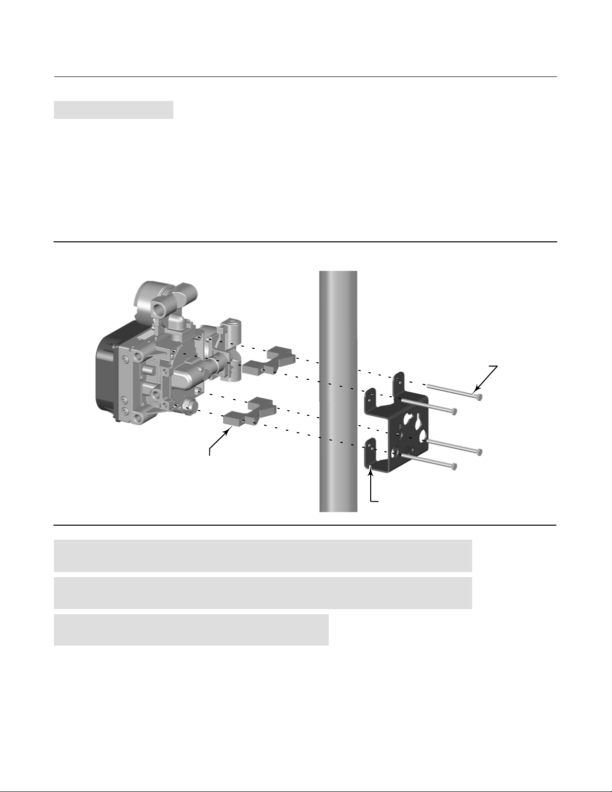
Pipestand Mounting
1. Position a standoff on the back of the DVC6005 base unit.
2. Using two 101.6 mm (4‐inch) 1/4‐20 hex head screws loosely attach the base unit to the pipestand with the
mounting bracket.
3. Position the second standoff, then, using the remaining 101.6 mm (4‐inch) hex head screws, securely fasten the
base unit to the pipe stand.
4. Tighten all screws.
5. Proceed to the appropriate remote feedback unit mounting procedure.
Figure 1. FIELDVUE DVC6005 Pipestand Mounting
4‐INCH 1/4‐20
HEX HEAD SCREW
STANDOFF
MOUNTING BRACKET
X0437
For DVC6015 remote feedback unit on sliding‐stem linear actuators up to
102 mm (4 inches) travel proceed to page 6
For DVC6025 remote feedback unit on long-stroke [102-610 mm (4-24 inch)]
travel sliding‐stem actuators and rotary actuators proceed to page 9
For DVC6035 remote feedback unit on
quarter‐turn rotary actuators proceed to page 12
4

Quick Start Guide
D103784X012
DVC6005 Digital Valve Controllers
March 2018
Wall Mounting
1. Install the wall mounting screws by using the mounting bracket as a template.
2. Install the mounting bracket to the back of the base unit using the spacers and screws provided in the mounting kit.
3. Slide the assembly on the wall mounting screws and tighten.
4. Proceed to the appropriate remote feedback unit mounting procedure.
Figure 2. FIELDVUE DVC6005 Wall Mounting
57
(2.25)
SPACER
1‐INCH 1/4‐20
HEX HEAD
SCREW
72
(2.82)
X0428
MOUNTING
BRACKET
10C1796‐A
For DVC6015 remote feedback unit on sliding‐stem linear actuators up to
102 mm (4 inches) travel proceed to page 6
For DVC6025 remote feedback unit on long-stroke [102-610 mm (4-24 inch)]
travel sliding‐stem actuators and rotary actuators proceed to page 9
For DVC6035 remote feedback unit on
quarter‐turn rotary actuators proceed to page 12
2 MOUNTING
HOLES
8.6/0.34
5

DVC6005 Digital Valve Controllers
March 2018
Quick Start Guide
D103784X012
DVC6015 Remote Mount Feedback Unit on Sliding‐Stem Linear Actuators up to
102 mm (4 inches) Travel
Note
If ordered as part of a control valve assembly, the factory mounts the DVC6015 remote feedback unit on the actuator. If you
purchased the remote feedback unit separately, you will need a mounting kit to mount the remote feedback unit on the actuator.
See the instructions that come with the mounting kit for detailed information on mounting the remote feedback unit to a specific
actuator model.
The DVC6015 remote feedback unit mounts on sliding‐stem actuators with up to 102 mm (4 inch) travel. Figure 3
shows a typical mounting on an actuator with up to 51 mm (2 inch) travel. Figure 4 shows a typical mounting on
actuators with 51 to 102 mm (2 to 4 inch) travel. For actuators with greater than 102 mm (4 inch) travel, see the
guidelines for mounting a DVC6025 remote feedback unit.
Figure 3. FIELDVUE DVC6015 Remote Feedback Unit Mounted on Sliding‐Stem Actuators with up to 2 Inches Travel
CAP SCREW, FLANGED
MACHINE SCREW
SHIELD
ADJUSTMENT ARM
CAP SCREW
PLAIN WASHER
X0910
CONNECTOR ARM
X0909
Refer to the following guidelines when mounting on sliding‐stem actuators with up to 4 inches of travel.
1. Isolate the control valve from the process line pressure and release pressure from both sides of the valve body. Shut
off all pressure lines to the actuator, releasing all pressure from the actuator. Use lock‐out procedures to be sure
that the above measures stay in effect while you work on the equipment.
6

Quick Start Guide
D103784X012
DVC6005 Digital Valve Controllers
March 2018
2. Attach the connector arm to the valve stem connector.
3. Attach the mounting bracket to the digital valve controller housing.
4. If valve travel exceeds 2 inches, a feedback arm extension is attached to the existing 2‐inch feedback arm. Remove
the existing bias spring from the 2‐inch feedback arm. Attach the feedback arm extension to the feedback arm
(key 79) as shown in figure 4.
5. Mount the remote feedback unit on the actuator as described in the mounting kit instructions.
Figure 4. FIELDVUE DVC6015 Remote Feedback Unit Mounted on Sliding‐Stem Actuators with 2 to 4 Inches Travel
FEEDBACK ARM
CAP SCREW, FLANGED
EXTENSION,
BIAS SPRING
ADJUSTMENT ARM
MACHINE
SCREW,
FLAT HEAD
LOCK WASHER
HEX NUT
SPACER
MACHINE
SCREW
X0908
SHIELD
MACHINE SCREW,
LOCK WASHER,
HEX NUT
CONNECTOR ARM
HEX NUT,
FLANGED
LOCK
WASHER
X0907
PLAIN
WASHER
6. Set the position of the feedback arm (key 79) on the remote feedback unit to the no air position by inserting the
alignment pin (key 46) through the hole on the feedback arm as follows:
D For air‐to‐open actuators (i.e., the actuator stem retracts into the actuator casing or cylinder as air pressure to
the casing or lower cylinder increases), insert the alignment pin into the hole marked “A”. For this style actuator,
the feedback arm rotates counterclockwise, from A to B, as air pressure to the casing or lower cylinder increases.
D For air‐to‐close actuators (i.e., the actuator stem extends from the actuator casing or cylinder as air pressure to
the casing or upper cylinder increases), insert the alignment pin into the hole marked “B”. For this style actuator,
the feedback arm rotates clockwise, from B to A, as air pressure to the casing or upper cylinder increases.
Note
When performing the following steps, ensure there is enough clearance between the adjustment arm and the feedback arm to
prevent interference with the bias spring.
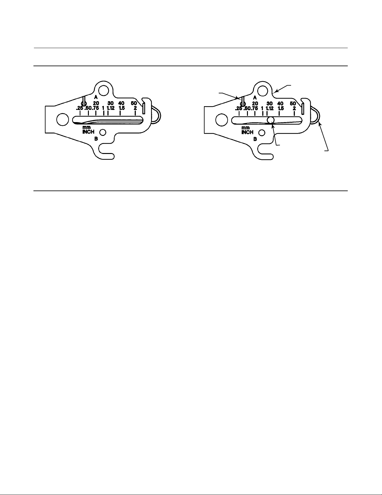
7. Apply lubricant to the pin of the adjustment arm. As shown in figure 5, place the pin into the slot of the feedback
arm or feedback arm extension so that the bias spring loads the pin against the side of the arm with the valve travel
markings.
7
DVC6005 Digital Valve Controllers
March 2018
Figure 5. Locating Adjustment Arm Pin in Feedback Arm
BIAS SPRING
Quick Start Guide
D103784X012
FEEDBACK ARM
ADJUSTMENT
ARM PIN
BIAS
SPRING
A7209‐1
SPRING RELAXED
SPRING UNDER TENSION OF
ADJUSTMENT ARM PIN
8. Install the external lock washer on the adjustment arm. Position the adjustment arm in the slot of the connector
arm and loosely install the flanged hex nut.
9. Slide the adjustment arm pin in the slot of the connector arm until the pin is in line with the desired valve travel
marking. Tighten the flanged hex nut.
10. Remove the alignment pin (key 46) and store it in the module base next to the I/P assembly.
11. After calibrating the instrument, attach the shield with two machine screws.
12. Proceed to Step 2—Connect the Pneumatic Tubing on page 15.
8

Quick Start Guide
D103784X012
DVC6005 Digital Valve Controllers
March 2018
DVC6025 Remote Feedback Unit on Long-Stroke [102-610 mm (4-24 inch) Travel]
Sliding‐Stem Actuators and Rotary Actuators
Note
If ordered as part of a control valve assembly, the factory mounts the DVC6025 remote feedback unit on the actuator. If you
purchased the remote feedback unit separately, you will need a mounting kit to mount the remote feedback unit on the actuator.
See the instructions that come with the mounting kit for detailed information on mounting the remote feedback unit to a specific
actuator model.
DVC6025 remote feedback units use a cam and roller as the feedback mechanism. Figure 6 shows an example of
mounting on sliding‐stem actuators with travels from 4 inches to 24 inches. Some long‐stroke applications will require
an actuator with a tapped lower yoke boss. Figures 7 and 8 show examples of mounting on rotary actuators.
Figure 6. FIELDVUE DVC6025 Remote Feedback Unit Mounted on Long‐Stroke Sliding‐Stem Actuator
CAM/ROLLER POSITION MARK
PLAIN WASHER
HEX NUT
STUD, CONT
THREAD
CAM
VENT
VENT ADAPTOR
X0914 X0913
SPACER
A
A
LOCK WASHER
CAP SCREW
CAP SCREW,
HEX SOCKET
MOUNTING PLATE
STUD,
CONT THREAD
HEX NUT
PLAIN WASHER
SECTION A‐A
As shown in figure 7, two feedback arms are available for the remote feedback unit. Most long‐stroke sliding‐stem and
rotary actuator installations use the long feedback arm [62 mm (2.45 inches) from roller to pivot point]. Installations
on 1051 size 33 and 1052 size 20 and 33 actuators use the short feedback arm [54 mm (2.13 inches) from roller to
pivot point]. Make sure the correct feedback arm is installed on the remote feedback unit before beginning the
mounting procedure.
9
 Loading...