

Page 1
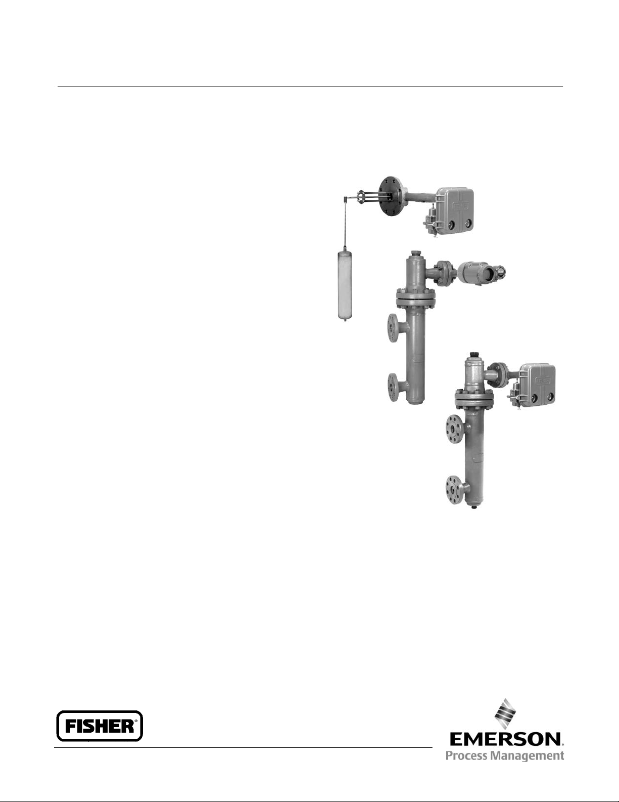
Product Bulletin
Sensor, Controller, and Transmitter Dimensions
D200039X012
September 2014
Fisherr 249 Sensor, Level Controller, and
Transmitter Dimensions
This bulletin contains dimensional information for
Fisher
displacer‐type sensors and for controllers and
transmitters used with these sensors. Dimensions are
subject to change and certified dimensions should be
requested for construction projects. Some of the
abbreviations used in this document are as follows:
NPT = National Pipe Thread, NPS = Nominal Pipe Size,
FF = Flat Face Flange, RF = Raised Face Flange, and
RTJ = Ring Type Joint Flange.
Flange specification references are ASME B16.1 for
CL125 and 250 and ASME 16.5 for CL150, 300, 600,
900, 1500 and 2500.
W8332
34.2:249
Contents
Caged Displacer for External Vessel Mounting
249: figure 1 and 2; tables 1, 2, 3, and 4
249B and 249BF: figure 3; tables 5, 6, 7, and 8
249C and 249K: figure 4; tables 9, 10, and 11
249L: figure 5
Cageless Displacer for Internal Vessel Mounting
Top Mounted.
249BP and 249P: figure 6; tables 12 and 13
249CP: figure 7; tables 14 and 15
Side Mounted.
249VS: figure 8, 9, 10, and 11
W7926
W8334
Cageless Displacer for Mounting on Customer
Supplied Cage or on Top of Vessel
249W: figure 12
Controllers and Transmitters
Fisher 2500 Controller / Transmitter: figure 13
FIELDVUEt DLC3010 / DLC3020f Digital Level
Controller: figure 14
www.Fisher.com
Page 2
Product Bulletin
34.2:249
September 2014
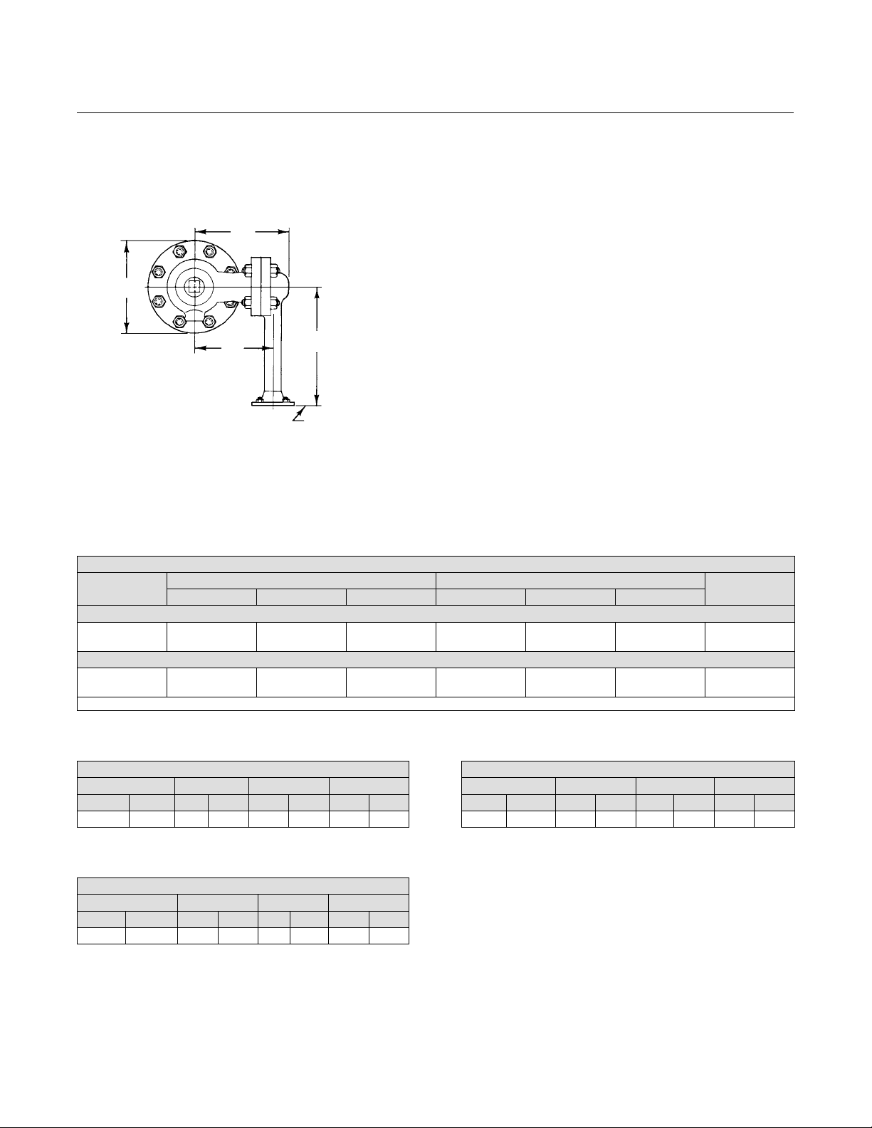
249
Figure 1. Fisher 249 Top View
244
(9.62)
241
(9.50)
Sensor, Controller, and Transmitter Dimensions
D200039X012
297
(11.69)
MATCH LINE (A)
mm
(INCH)
A1323‐1
203
(8.00)
TOP VIEW
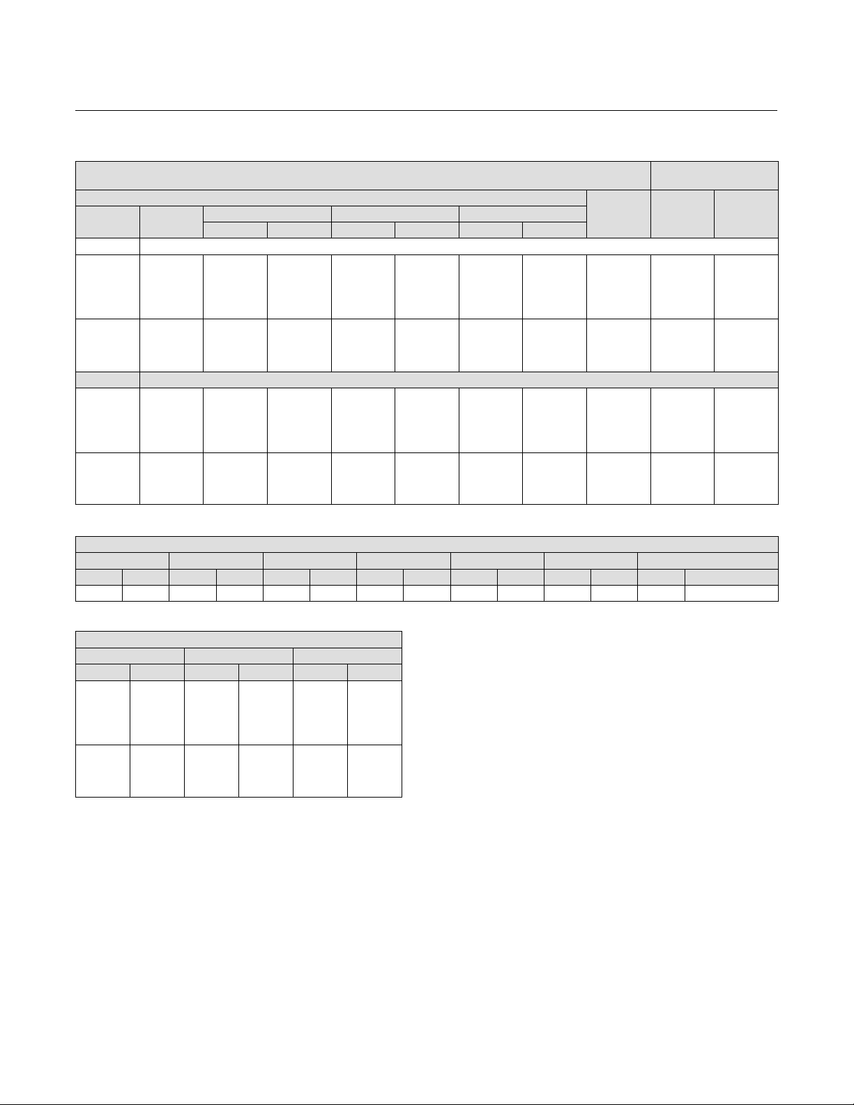
Table 1. Fisher 249 Dimensions F, M, and W for S‐1 and F‐1 Connections
S‐1 AND F‐1 CONNECTIONS
Displacer
Length
356
813
14
32
1. Scrd is 1‐1/2 and 2 NPT. Flanges in NPS 2 only.
CL125 FF Scrd NPT CL250 RF Scrd NPT CL125 FF CL250 RF
562
1019
22.12
40.12
Table 2. Fisher 249 Dimensions F, M, and W for S‐2
Connections
S‐2 CONNECTIONS: 1‐1/2 NPT, CL250
Displacer Length F M W
mm Inch mm Inch mm Inch mm Inch
356 14 657 25.88 241 9.50 394 15.5
F M
mm
495
953
19.50
37.50
575
1032
22.62
40.62
241
470
Inches
9.50
18.50
Table 4. Fisher 249 Dimensions F, M, and W for S‐4
Connections
Displacer Length F M W
mm Inch mm Inch mm Inch mm Inch
356 14 445 17.50 241 9.50 394 15.5
(1)
279
508
11.00
20.00
S‐4 CONNECTIONS: 1‐1/2 NPT, CL250
286
514
11.25
20.25
W
406
864
16.00
34.00
Table 3. Fisher 249 Dimensions F, M, and W for S‐3
Connections
S‐3 CONNECTIONS: 1‐1/2 NPT, CL250
Displacer Length F M W
mm Inch mm Inch mm Inch mm Inch
356 14 356 14.00 241 9.50 394 15.5
2
Page 3
Sensor, Controller, and Transmitter Dimensions
D200039X012
Figure 2. Fisher 249 Side View (see tables 1, 2, 3, and 4)
Product Bulletin
34.2:249
September 2014
W
F
A1324‐1
S‐1 AND F‐1
TOP AND BOTTOM CONNECTIONS
M
CL125 ‐ 1/2‐14 NPT
CL250 ‐ 3/4‐14 NPT
44
(1.75)
MATCH LINE (B)
44
(1.75)
302
(11.88)
W
F
89
A1326‐1
(3.50)
S‐3
UPPER AND LOWER SIDE CONNECTIONS
M
CL125 ‐ 1/2‐14 NPT
CL250 ‐ 3/4‐14 NPT
44
(1.75)
MATCH LINE (B)
44
(1.75)
F
W
CL125 ‐ 1/2‐14 NPT
CL250 ‐ 3/4‐14 NPT
A1325‐1
89
(3.50)
S‐2
TOP AND LOWER SIDE CONNECTIONS
MATCH LINE (B)
M
CL125 ‐ 1/2‐14 NPT
CL250 ‐ 3/4‐14 NPT
A1327‐1
302
(11.88)
W
F
M
89
(3.50)
MATCH LINE (B)
S‐4
UPPER SIDE AND BOTTOM CONNECTIONS
SIDE VIEW
mm
(INCH)
3
Page 4
Product Bulletin
34.2:249
September 2014
Sensor, Controller, and Transmitter Dimensions
249B and 249BF (NPS 1‐1/2 and 2 End Connections)
Figure 3. Fisher 249B and 249BF (see tables 5, 6, 7, and 8)
244
(9.62)
229
(9.00)
203
(8.00)
297
(11.69)
421
(16.56)
1‐1/2 11‐1/2 NPT
103
(4.06)
MATCH
LINE (B)
D200039X012
A1328‐1
MATCH LINE (A)
TOP VIEW
MATCH
LINE (B)
3/4‐14 NPT
A1329‐1
G
W
F
M
S‐1 AND F‐1
TOP AND BOTTOM CONNECTIONS
A1330‐1
106
(4.19)
G
F
W
A
M
MATCH
LINE (B)
3/4‐14 NPT
S‐2 AND F‐2
TOP AND LOWER SIDE CONNECTIONS
103
(4.06)
103
(4.06)
G
A
A
M
3/4‐14 NPT
(4.19)
A1331‐1
106
F
W
S‐3 AND F‐3
UPPER AND LOWER SIDE CONNECTIONS
1‐1/2 11‐1/2 NPT
103
(4.06)
421
(16.56)
G
A
W
F
M
A1332‐1
MATCH
LINE (B)
3/4‐14 NPT
S‐4 AND F‐4
UPPER SIDE AND BOTTOM CONNECTIONS
mm
(INCH)
SIDE VIEW
4
Page 5

Sensor, Controller, and Transmitter Dimensions
D200039X012
Table 5. Fisher 249B and 249BF S‐1, F‐1, S‐4, and F‐4 Connections
Conn.
Style
S‐1
and
F‐1
(mm)
S‐1
and
F‐1
(Inch)
S‐4
and
F‐4
(mm)
S‐4
and
F‐4
(Inch)
Dis‐
placer
Length
356
813
1219
1524
1829
2134
2438
2743
3048
14
32
48
60
72
84
96
108
120
356
813
1219
1524
1829
2134
2438
2743
3048
14
32
48
60
72
84
96
108
120
Scrd
NPT
586
1043
1449
1754
2058
2364
2669
2973
3278
23.06
41.06
57.06
69.06
81.06
93.06
105.06
117.06
129.06
462
919
1326
1630
1935
2240
2545
2850
3154
18.19
36.19
52.19
64.19
76.19
88.19
100.19
112.19
124.19
CL150 CL300 CL600
RF RTJ RF RTJ RF RTJ RF RTJ RF RTJ RF RTJ
662
1119
1526
1830
2135
2440
2745
3050
3354
26.06
44.06
60.06
72.06
84.06
96.06
108.06
120.06
132.06
500
957
1364
1669
1973
2278
2583
2888
3193
19.69
37.69
53.69
65.69
77.69
86.69
101.69
113.69
125.69
675
1132
1538
1843
2148
2453
2757
3062
3367
26.56
44.56
60.56
72.56
84.56
96.56
108.56
120.56
132.56
506
964
1370
1675
1980
2284
2589
2894
3199
19.94
37.94
53.94
65.94
77.94
89.94
101.94
113.94
125.94
F M
668
1126
1532
1836
2141
2446
2751
3056
3361
26.31
44.31
60.31
72.31
84.31
96.31
108.31
120.31
132.31
503
960
1367
1672
1976
2281
2586
2891
3196
19.81
37.81
53.81
65.81
77.81
89.81
101.81
113.81
125.81
684
1141
1548
1853
2157
2462
2767
3072
3377
26.94
44.94
60.94
72.94
84.94
96.94
108.94
120.94
132.94
511
968
1375
1679
1984
2288
2593
2899
3203
20.12
38.12
54.12
66.12
78.12
90.12
102.12
114.12
126.12
687
1145
1551
1856
2160
2465
2770
3075
3380
27.06
45.06
61.06
73.06
85.06
97.06
109.06
121.06
133.06
513
970
1376
1681
1986
2291
2596
2900
3265
20.19
38.19
54.19
66.19
78.19
90.19
102.19
114.19
126.19
691
1148
1554
1859
2164
2469
2773
3078
3383
27.19
45.19
61.19
73.19
85.19
97.19
109.19
121.19
133.19
514
972
1378
1683
1988
2292
2597
2902
3267
20.25
38.25
54.25
66.25
78.25
90.25
102.25
114.25
126.25
Scrd
NPT
284
513
716
866
1021
1173
1326
1478
1630
11.19
20.19
28.19
34.19
40.19
46.19
52.19
58.19
64.19
284
513
716
866
1021
1173
1326
1478
1630
11.19
20.19
28.19
34.19
40.19
46.19
52.19
58.19
64.19
Product Bulletin
September 2014
CL150 CL300 CL600
322
551
754
907
1059
1211
1364
1516
1669
12.69
21.69
29.69
35.69
41.69
47.69
53.69
59.69
65.69
322
551
754
907
1059
1211
1364
1516
1669
12.69
21.69
29.69
35.69
41.69
47.69
53.69
59.69
65.69
329
557
760
913
1065
1218
1370
1522
1675
12.94
21.94
29.94
35.94
41.94
47.94
53.94
59.94
65.94
329
557
760
913
1065
1218
1370
1522
1675
12.94
21.94
29.94
35.94
41.94
47.94
53.94
59.94
65.94
325
554
757
910
1062
1214
1367
1519
1672
12.81
21.81
29.81
35.81
41.81
47.81
53.81
59.81
65.81
325
554
757
910
1062
1214
1367
1519
1672
12.81
21.81
29.81
35.81
41.81
47.81
53.81
59.81
65.81
333
562
765
917
1070
1222
1375
1527
1679
13.12
22.12
30.12
36.12
42.12
48.12
54.12
60.12
66.12
333
562
765
917
1070
1222
1375
1527
1679
13.12
22.12
30.12
36.12
42.12
48.12
54.12
60.12
66.12
34.2:249
335
564
767
919
1072
1224
1376
1529
1681
13.19
22.19
30.19
36.19
42.19
48.19
54.19
60.19
66.19
335
564
767
919
1072
1224
1376
1529
1681
13.19
22.19
30.19
36.19
42.19
48.19
54.19
60.19
66.19
337
565
768
921
1073
1226
1378
1530
1683
13.25
22.25
30.25
36.25
42.25
48.25
54.25
60.25
66.25
337
565
768
921
1073
1226
1378
1530
1683
13.25
22.25
30.25
36.25
42.25
48.25
54.25
60.25
66.25
5
Page 6
Product Bulletin
34.2:249
September 2014
Table 6. Fisher 249B and 249BF S‐2, F‐2, S‐3, and F‐3 Connections
S‐2 AND F‐2 CONNECTIONS
F
Displacer
Length
mm mm
356
813
1219
1524
1829
2134
2438
2743
3048
Inches Inches
14
32
48
60
72
84
96
108
120
Scrd
NPT
480
937
1343
1648
1953
2258
2562
2867
3172
18.88
36.88
52.88
64.88
76.88
88.88
100.88
112.88
124.88
CL150 CL300 CL600
RF RTJ RF RTJ RF RTJ
518
975
1381
1686
1991
2296
2600
2905
3210
20.38
38.38
54.38
66.38
78.38
90.38
102.38
114.38
126.38
524
981
1387
1692
1997
2302
2607
2911
3216
20.62
38.62
54.62
66.62
78.62
90.62
102.62
114.62
126.62
521
978
1384
1689
1994
2299
2604
2908
3213
20.50
38.50
54.50
66.50
78.50
90.50
102.50
114.50
126.50
Sensor, Controller, and Transmitter Dimensions
529
986
1392
1697
2002
2307
2611
2916
3221
20.81
38.81
54.81
66.81
78.81
90.81
102.81
114.81
126.81
530
988
1394
1699
2004
2308
2613
2918
3223
20.88
38.88
54.88
66.88
78.88
90.88
102.88
114.88
126.88
532
989
1395
1700
2005
2310
2615
2919
3224
20.94
38.94
54.94
66.94
78.94
90.94
102.94
114.94
126.94
D200039X012
S‐3 AND F‐3
CONNECTIONS
M F M
284
513
716
866
1021
1173
1326
1478
1630
11.19
20.19
28.19
34.19
40.19
46.19
52.19
58.19
64.19
356
813
1219
1524
1829
2134
2438
2743
3048
14.00
32.00
48.00
60.00
72.00
84.00
96.00
108.00
120.00
284
513
716
866
1021
1173
1326
1478
1630
11.19
20.19
28.19
34.19
40.19
46.19
52.19
58.19
64.19
Table 7. Fisher 249B and 249BF Dimension A
A (COMMON DIMENSION)
Scrd NPT CL150 RF CL150 RTJ CL300 RF CL300 RTJ CL600 RF CL600 RTJ
mm Inch mm Inch mm Inch mm Inch mm Inch mm Inch mm Inch
121 4.75 145 5.69 151 5.94 148 5.81 155 6.12 157 6.19 159 6.25
Table 8. Fisher 249B and 249BF Dimensions W and G
COMMON DIMENSION
Displacer Length W G
mm Inch mm Inch mm Inch
356
813
1219
1524
1829
2134
2438
2743
3048
14
32
48
60
72
84
96
108
120
394
851
1257
1562
1867
2172
2477
2781
3086
15.50
33.50
49.50
61.50
73.50
85.50
97.50
109.50
121.50
197
425
629
781
933
1086
1238
1391
1543
7.75
16.75
24.75
30.75
36.75
42.75
48.75
54.75
60.75
6
Page 7

Sensor, Controller, and Transmitter Dimensions
D200039X012
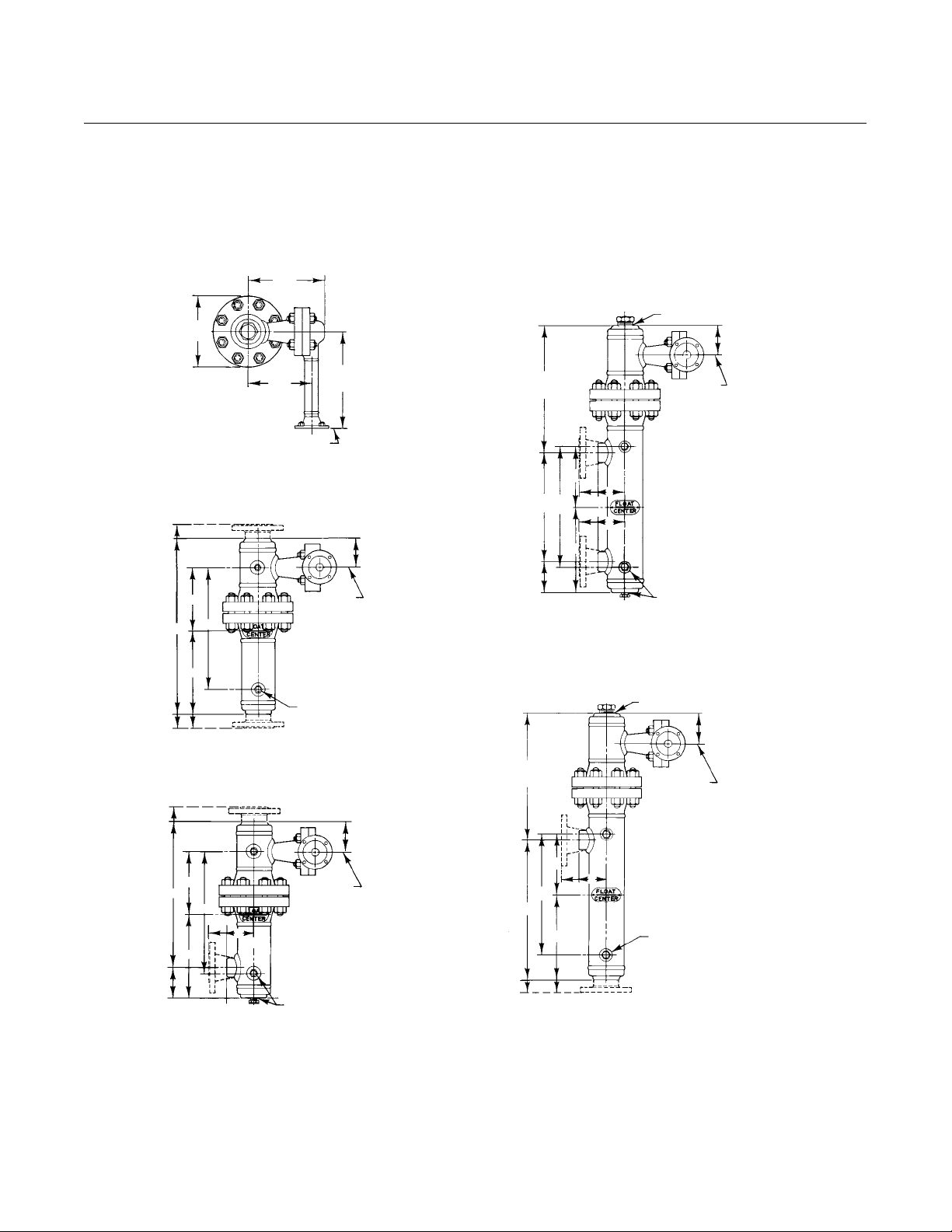
249C and 249K (NPS 1‐1/2 & 2 End Connections)
Figure 4. Fisher 249C and 249K (see tables 9, 10, and 11)
210
(8.25)
308
A1343‐1
MATCH LINE (A)
249C ONLY
168
(6.62)
297
(11.69)
TOP VIEW
A1363‐1
(12.12)
267
(10.50)
MATCH LINE (A)
249K ONLY
402
(15.81)
1
213
(8.38)
F
3
57
(2.25)
A
M
Product Bulletin
34.2:249
September 2014
1‐1/2 11‐1/2 NPT (249C)
2 11‐1/2 NPT (249K)
MATCH
LINE (B)
3
57
(2.25)
F
M
A1340‐1
S‐1 AND F‐1
TOP AND BOTTOM CONNECTIONS
Note:
1 389 (15.31) for 249K
2 119 (4.69) for 249K
3 102 (4.00) for 249K
MATCH
LINE (B)
2
A1344‐1
94
(3.69)
57
(2.25)
F
A
M
3
MATCH
LINE (B)
1/2‐14 NPT
S‐2 AND F‐2
TOP AND LOWER SIDE CONNECTIONS
94
2
(3.69)
A
1/2‐14 NPT
S‐3 AND F‐3
UPPER AND LOWER SIDE CONNECTIONS
1‐1/2 11‐1/2 NPT (249C)
2 11‐1/2 NPT (249K)
MATCH
LINE (B)
A1342‐1
3
57
(2.25)
213
1
(8.38)
A
F
M
S‐4 AND F‐4
UPPER SIDE AND BOTTOM CONNECTIONS
7
Page 8

Product Bulletin
34.2:249
September 2014
Table 9. Fisher 249C and 249K Dimensions F and M, S‐1, F‐1, S‐4, and F‐4 Connections
Conn.
Style
S‐1
and
F‐1
(mm)
S‐1
and
F‐1
(In.)
S‐4
and
F‐4
(mm)
S‐4
and
F‐4
(In.)
Dis‐
placer
Length
356
813
1219
1524
1829
2134
2438
14
32
48
60
72
84
96
356
813
1219
1524
1829
2134
2438
14
32
48
60
72
84
96
Scrd
NPT
489
946
1353
1357
1962
‐‐‐
2826
19.25
37.25
53.25
65.25
77.25
‐‐‐
111.25
409
867
1273
1518
1883
‐‐‐
‐‐‐
16.12
34.12
50.12
62.12
74.12
‐‐‐
‐‐‐
CL150 CL300 CL600
RF RTJ RF RTJ RF RTJ RF RTJ RF RTJ RF RTJ
530
988
1394
1699
2004
2308
2613
20.88
38.88
54.88
66.88
78.88
90.88
102.88
432
889
1295
1600
1905
2210
2515
17.00
35.00
51.00
63.00
75.00
87.00
99.00
F M F M
543
546
559
1000
1407
1711
2016
‐‐‐
‐‐‐
21.38
39.38
55.38
67.38
79.38
‐‐‐
‐‐‐
438
895
1302
1607
1911
‐‐‐
‐‐‐
17.25
35.25
51.25
63.25
75.25
‐‐‐
‐‐‐
1003
1410
1715
2019
2324
2781
21.50
39.50
55.50
67.50
79.50
91.50
109.50
438
895
1302
1607
1911
‐‐‐
‐‐‐
17.25
35.25
51.25
63.25
75.25
‐‐‐
‐‐‐
1016
1422
1727
2032
2337
‐‐‐
22.00
40.00
56.00
68.00
80.00
92.00
‐‐‐
445
902
1308
1613
1918
‐‐‐
‐‐‐
17.50
35.50
51.50
63.50
75.50
‐‐‐
‐‐‐
560
1018
1424
1729
2034
‐‐‐
‐‐‐
22.06
40.06
56.06
68.06
80.06
‐‐‐
‐‐‐
446
903
1310
1614
1919
‐‐‐
‐‐‐
17.56
35.56
51.56
63.56
75.56
‐‐‐
‐‐‐
Sensor, Controller, and Transmitter Dimensions
249C 249K
CL150 CL300 CL600
257
264
492
695
848
1000
‐‐‐
‐‐‐
10.38
19.38
27.38
33.38
39.38
‐‐‐
‐‐‐
260
489
692
845
997
‐‐‐
‐‐‐
10.25
19.25
27.25
33.25
39.25
‐‐‐
‐‐‐
264
492
695
848
1000
1153
1305
10.38
19.38
27.38
33.38
39.38
45.38
51.38
260
489
692
845
997
‐‐‐
‐‐‐
10.25
19.25
27.25
33.25
39.25
‐‐‐
‐‐‐
1006
1159
10.62
19.62
27.62
33.62
39.62
45.62
1003
10.50
19.50
27.50
33.50
39.50
486
689
841
994
1146
1298
10.12
19.12
27.12
33.12
39.12
45.12
51.12
254
483
686
838
991
1143
1295
10.00
19.00
27.00
33.00
39.00
45.00
51.00
560
1018
1424
1729
2034
‐‐‐
‐‐‐
22.06
40.06
56.06
68.06
80.06
‐‐‐
‐‐‐
446
903
1310
1614
1919
‐‐‐
‐‐‐
17.56
35.56
51.56
63.56
75.56
‐‐‐
‐‐‐
Scrd
NPT
235
464
667
819
972
‐‐‐
127
9.25
18.25
26.25
32.25
38.25
‐‐‐
50.25
232
460
667
816
968
‐‐‐
‐‐‐
9.12
18.12
26.12
32.12
38.12
‐‐‐
‐‐‐
270
498
702
854
‐‐‐
‐‐‐
267
495
699
851
‐‐‐
‐‐‐
‐‐‐
‐‐‐
272
500
703
856
1008
‐‐‐
‐‐‐
10.69
19.69
27.69
33.69
39.69
‐‐‐
‐‐‐
268
497
700
852
1005
‐‐‐
‐‐‐
10.56
19.56
27.56
33.56
39.56
‐‐‐
‐‐‐
272
500
703
856
1008
‐‐‐
‐‐‐
10.69
19.69
27.69
33.69
39.69
‐‐‐
‐‐‐
268
497
700
852
1005
‐‐‐
‐‐‐
10.56
19.56
27.56
33.56
39.56
‐‐‐
‐‐‐
D200039X012
NPS
NPS 2
1‐1/2
Flg.
Flg.
645
654
1102
1111
‐‐‐
‐‐‐
‐‐‐
‐‐‐
‐‐‐
‐‐‐
‐‐‐
‐‐‐
‐‐‐
‐‐‐
25.38
25.75
43.38
43.75
‐‐‐
‐‐‐
‐‐‐
‐‐‐
‐‐‐
‐‐‐
‐‐‐
‐‐‐
‐‐‐
‐‐‐
483
483
940
940
‐‐‐
‐‐‐
‐‐‐
‐‐‐
‐‐‐
‐‐‐
‐‐‐
‐‐‐
‐‐‐
‐‐‐
19.00
19.00
37.00
37.00
‐‐‐
‐‐‐
‐‐‐
‐‐‐
‐‐‐
‐‐‐
‐‐‐
‐‐‐
‐‐‐
‐‐‐
Flg.
305
533
‐‐‐
‐‐‐
‐‐‐
‐‐‐
‐‐‐
12.00
21.00
‐‐‐
‐‐‐
‐‐‐
‐‐‐
‐‐‐
305
533
‐‐‐
‐‐‐
‐‐‐
‐‐‐
‐‐‐
12.00
21.00
‐‐‐
‐‐‐
‐‐‐
‐‐‐
‐‐‐
Table 10. Fisher 249C and 249K, Dimensions F and M, S‐2, F‐2, S‐3, and F‐3 Connections
S‐2 AND F‐2 CONNECTIONS S‐3 AND F‐3 CONNECTIONS
249C 249K 249C 249K
Dis‐
placer
Length
Scrd
NPT
F
CL150 CL300 CL600
RF RTJ RF RTJ RF RTJ
M
NPS
1‐1/2
Flg.
F
NPS 2
Flg.
M F M F M
mm
356
813
1219
1524
1829
2134
2438
432
889
1295
1600
1905
‐‐‐
‐‐‐
451
908
1314
1619
1924
2229
‐‐‐
457
914
1321
1626
1930
‐‐‐
‐‐‐
460
917
1324
1629
1933
2238
‐‐‐
467
924
1330
1635
1940
‐‐‐
‐‐‐
467
924
1330
1635
1940
‐‐‐
‐‐‐
467
924
1330
1635
1940
‐‐‐
‐‐‐
272
500
703
856
1008
1161
‐‐‐
518
975
‐‐‐
‐‐‐
‐‐‐
‐‐‐
‐‐‐
527
984
‐‐‐
‐‐‐
‐‐‐
‐‐‐
‐‐‐
297
526
‐‐‐
‐‐‐
‐‐‐
‐‐‐
‐‐‐
356
813
1219
1524
1829
2134
2438
272
500
703
856
1008
1161
1313
356
813
‐‐‐
‐‐‐
‐‐‐
‐‐‐
‐‐‐
Inches
14
32
48
60
72
84
96
17.00
35.00
51.00
63.00
75.00
17.75
35.75
51.75
63.75
75.75
‐‐‐
87.75
‐‐‐
18.00
36.00
52.00
64.00
76.00
‐‐‐
18.12
36.12
52.12
64.12
76.12
‐‐‐
88.12
‐‐‐
18.38
36.38
52.38
64.38
76.38
‐‐‐
18.38
36.38
52.38
64.38
76.38
‐‐‐
‐‐‐
18.38
36.38
52.38
64.38
76.38
‐‐‐
‐‐‐
10.69
19.69
27.69
33.69
39.69
‐‐‐
45.69
‐‐‐
20.38
38.38
‐‐‐
20.75
38.75
‐‐‐
‐‐‐
‐‐‐
‐‐‐
‐‐‐
11.69
20.69
‐‐‐
‐‐‐
‐‐‐
‐‐‐
‐‐‐
14.00
32.00
‐‐‐
48.00
‐‐‐
60.00
‐‐‐
72.00
‐‐‐
84.00
‐‐‐
96.00
10.69
19.69
27.69
33.69
39.69
45.69
51.69
14.00
32.00
‐‐‐
‐‐‐
‐‐‐
‐‐‐
‐‐‐
Table 11. Fisher 249C and 249K Dimension A
END CONNECTION
SIZE
249C
SCREWED
249C
CL150 RF
DN NPS mm Inch mm Inch mm Inch mm Inch mm Inch mm Inch
40
50
1‐1/2
2
102
102
4.00
4.00
111
111
4.38
4.38
249C
CL150 RTJ
CL300 RF
117
117
4.62
4.62
249C
CL300 RTJ
122
125
4.81
4.94
249C
CL600 RF or RTJ
125
125
4.94
4.94
249K
CL1500 FLANGES
148
168
297
526
‐‐‐
‐‐‐
‐‐‐
‐‐‐
‐‐‐
11.69
20.69
‐‐‐
‐‐‐
‐‐‐
‐‐‐
‐‐‐
5.81
6.62
8
Page 9

Sensor, Controller, and Transmitter Dimensions
D200039X012
249L
Product Bulletin
34.2:249
September 2014
Figure 5. Fisher 249L
356
(14.00)
A1346‐1
DISPLACER
LENGTH
356
813
14
32
1. 249L Sensor has CL2500 RTJ flanges.
90
(3.56)
MATCH LINE (A)
TOP VIEW
(1)
F‐1
783
1240
30.81
48.81
295
(11.62)
230
(9.06)
DIMENSION F
(1)
F‐2
mm
629
1086
INCHES
24.75
42.75
NPS 1 RTJ FLG.
F‐3
356
813
14.00
32.00
406
(16.00)
(1)
F‐4
510
967
20.06
38.06
(1)
137
(5.38)
90
(3.56)
F
F1
TOP AND BOTTOM CONNECTIONS
A1347‐1
NPS 1 RTJ FLG.
MATCH
LINE (B)
NPS 2 RTJ FLG.
137
(5.38)
F
135
(5.31)
NPS 2 RTJ FLG.
A1349‐1
249
(9.81)
F2
TOP AND LOWER SIDE CONNECTIONS
MATCH
LINE (B)
1/2 14 NPT
673
(26.50)
F
135
(5.31)
249
A1345‐1
(9.81)
F3
UPPER AND LOWER SIDE CONNECTION
(NPS 2 RTJ FLG.)
SIDE VIEW
MATCH
LINE (B)
1/2 14 NPT
673
(26.50)
MATCH
LINE (B)
F
249
(9.81)
A1348‐1
F4
UPPER SIDE AND BOTTOM CONNECTIONS
(NPS 2 RTJ FLG.)
(INCH)
mm
9
Page 10

Product Bulletin
34.2:249
September 2014
249BP and 249P
Figure 6. Fisher 249BP and 249P (see tables 12 and 13)
Sensor, Controller, and Transmitter Dimensions
D200039X012
A1357‐1
R
MATCH LINE (A)
P
G
F
244
(9.62)
203
(8.00)
TOP VIEW
1‐1/2 11‐1/2 NPT
MATCH
LINE (B)
297
(11.69)
(4.06)
103
A1358‐1
R
44
(1.75)
P
G
F
244
(9.62)
297
203
(6.00)
MATCH LINE (A)
TOP VIEW
(11.69)
1‐1/2 11‐1/2 NPT THROUGH CL600
2 11‐1/2 NPT FOR CL900 AND CL1500
MATCH
LINE (B)
A1356‐1
D
SIDE VIEW
249BP
Table 12. Fisher 249BP and 249P Dimension D, F, and G
STANDARD DISPLACER AND STEM COMBINATIONS
D F
mm Inch mm Inch
76
51
41
38
35
32
29
25
25
1. If not specified, G dimension will be 305 mm (12 inches).
10
3.00
2.00
1.62
1.50
1.38
1.25
1.12
1.00
1.00
356
813
1219
1524
1829
2134
2438
2743
3048
14.00
32.00
48.00
60.00
72.00
84.00
96.00
108.00
120.00
A1355‐1
(1)
G
Specify.
Maximum
length is 1372
mm (54 inch)
D
SIDE VIEW
249P
mm
(INCH)
Page 11

Sensor, Controller, and Transmitter Dimensions
D200039X012
Table 13. Fisher 249BP and 249P Dimension P and R
CL150 CL300 CL600 CL900 CL1500
RF RTJ RF RTJ RF RTJ RF RTJ RF RTJ
238
240
243
229
279
343
214
216
219
229
279
343
9.38
9.44
9.56
9.00
11.00
13.50
8.44
8.50
8.62
9.00
11.00
13.50
244
‐‐‐
‐‐‐
229
‐‐‐
‐‐‐
221
‐‐‐
‐‐‐
‐‐‐
‐‐‐
‐‐‐
9.62
‐‐‐
‐‐‐
9.00
‐‐‐
‐‐‐
8.69
‐‐‐
‐‐‐
9.00
‐‐‐
‐‐‐
DIMENSION
P
R
P
R
DIMENSION
P
R
P
R
TYPE
NO.
249BP
249P
TYPE
NO.
249BP
249P
FLANGE
SIZE, NPS
4
6
8
4
6
8
4
6
8
4
6
8
FLANGE
SIZE, NPS
4
6
8
4
6
8
4
6
8
4
6
8
CL125FFCL250
‐‐‐
‐‐‐
‐‐‐
‐‐‐
‐‐‐
‐‐‐
214
216
219
229
279
343
‐‐‐
‐‐‐
‐‐‐
‐‐‐
‐‐‐
‐‐‐
8.44
8.50
8.62
9.00
11.00
13.50
RF
‐‐‐
‐‐‐
‐‐‐
‐‐‐
‐‐‐
‐‐‐
222
227
232
254
318
381
‐‐‐
‐‐‐
‐‐‐
‐‐‐
‐‐‐
‐‐‐
8.75
8.94
9.12
10.00
12.50
15.00
256
‐‐‐
‐‐‐
254
318
381
222
227
232
254
318
381
9.74
9.94
10.12
10.00
12.50
15.00
8.75
8.94
9.12
10.00
12.50
15.00
270
‐‐‐
‐‐‐
254
‐‐‐
‐‐‐
230
‐‐‐
‐‐‐
254
‐‐‐
‐‐‐
Inches
10.06
‐‐‐
‐‐‐
10.00
‐‐‐
‐‐‐
9.06
‐‐‐
‐‐‐
10.00
‐‐‐
‐‐‐
mm
272
‐‐‐
‐‐‐
273
‐‐‐
‐‐‐
‐‐‐
244
‐‐‐
‐‐‐
356
‐‐‐
10.62
‐‐‐
‐‐‐
10.75
‐‐‐
‐‐‐
‐‐‐
9.62
‐‐‐
‐‐‐
14.00
‐‐‐
‐‐‐
‐‐‐
‐‐‐
273
‐‐‐
‐‐‐
236
‐‐‐
‐‐‐
273
‐‐‐
‐‐‐
10.69
‐‐‐
‐‐‐
10.75
‐‐‐
‐‐‐
9.31
‐‐‐
‐‐‐
10.75
‐‐‐
‐‐‐
Product Bulletin
September 2014
‐‐‐
‐‐‐
‐‐‐
‐‐‐
‐‐‐
‐‐‐
303
‐‐‐
‐‐‐
292
‐‐‐
‐‐‐
‐‐‐
‐‐‐
‐‐‐
‐‐‐
‐‐‐
‐‐‐
11.94
‐‐‐
‐‐‐
11.50
‐‐‐
‐‐‐
‐‐‐
‐‐‐
‐‐‐
‐‐‐
‐‐‐
‐‐‐
305
‐‐‐
‐‐‐
292
‐‐‐
‐‐‐
‐‐‐
‐‐‐
‐‐‐
‐‐‐
‐‐‐
‐‐‐
12.00
‐‐‐
‐‐‐
11.50
‐‐‐
‐‐‐
34.2:249
‐‐‐
‐‐‐
‐‐‐
‐‐‐
‐‐‐
‐‐‐
313
‐‐‐
‐‐‐
311
‐‐‐
‐‐‐
‐‐‐
‐‐‐
‐‐‐
‐‐‐
‐‐‐
‐‐‐
12.31
‐‐‐
‐‐‐
12.25
‐‐‐
‐‐‐
‐‐‐
‐‐‐
‐‐‐
‐‐‐
‐‐‐
‐‐‐
314
‐‐‐
‐‐‐
311
‐‐‐
‐‐‐
‐‐‐
‐‐‐
‐‐‐
‐‐‐
‐‐‐
‐‐‐
12.38
‐‐‐
‐‐‐
12.25
‐‐‐
‐‐‐
11
Page 12

Product Bulletin
34.2:249
September 2014
249CP (NPS 3 RF Flanged)
Figure 7. Fisher 249CP (see tables 14 and 15)
Sensor, Controller, and Transmitter Dimensions
D200039X012
210
(8.25)
297
(11.69)
A1351‐1
168
(6.62)
MATCH LINE (A)
TOP VIEW
Table 14. Fisher 249CP Dimensions D, F, and G
STANDARD DISPLACER AND STEM COMBINATIONS
D F
mm Inch mm Inch
60
38
32
1. If not specified, G dimension will be 305 mm (12 inches).
2.38
1.50
1.25
356
813
1219
14.00
32.00
48.00
Specify.
Maximum
length is 1372
mm (54 inches)
65
(2.56)
P
MATCH
LINE (B)
G
F
A1352‐1
D
SIDE VIEW
mm
(INCH)
Table 15. Fisher 249CP Dimension P
P
(1)
G
CL150 RF CL300 RF CL600 RF
mm Inch mm Inch mm Inch
191 7.50 200 7.88 210 8.25
12
Page 13

Product Bulletin
Sensor, Controller, and Transmitter Dimensions
D200039X012
September 2014
249VS
Figure 8. Fisher 249VS with DLC3010 / DLC3020f Digital Level Controller Controller Envelope Dimensions;
Flanged Connections
34.2:249
139.7
(5.50)
606.1
(23.86)
76.2
(3.00)
305
(12.00)
343.6
(13.53)
305
(12.00)
343.6
(13.53)
76.2
(3.00)
LEFT‐HAND MOUNT RIGHT‐HAND MOUNT
85.1
(3.35)
77.7
(3.06)
77.7
(3.06)
85.1
(3.35)
139.7
(5.50)
606.1
(23.86)
66
(2.60)
59.5
(2.34)
59.5
(2.34)
139.4
(5.49)
171.5
(6.75)
Notes:
1 Dimension G is customer specified
2 Displacer length illustrated is 14 inches
GE33695
1/2‐14 NPT
2 PLACES
76.2
(3.00)
1
(14.00)
G
355.3
G
355.3
(14.00)
1
76.2
(3.00)
59.5
(2.34)
712.5
(28.05)
HEAT INSULATOR EXTENSION
139.4
(5.49)
59.5
(2.34)
66
(2.60)
(INCH)
171.5
(6.75)
mm
13
Page 14

Product Bulletin
34.2:249
September 2014
Figure 9. Fisher 249VS with DLC3010 / DLC3020f Digital Level Controller Envelope Dimensions; Butt Weld End
Sensor, Controller, and Transmitter Dimensions
D200039X012
607
(23.88)
59
(2.34)
A
139
(5.49)
344
(13.53)
BUTT WELD END PER CHART
j
78
(3.06)
BUTT WELD END
BWE SCHED 40
CL600
BWE SCHED 80
CL900
BWE SCHED 160
CL1500
BWE SCHED XXS
CL2500
BUTT WELD END PER CHART
j
78
(3.06)
A
2.00
2.17
2.57
2.85
(13.53)
59
(2.34)
344
A
607
(23.88)
139
(5.49)
LEFT‐HAND MOUNT RIGHT‐HAND MOUNT
403
(15.87)
DLC3010 / DLC3020f
1/2‐14 NPT
OUTLET CONN (2 PLACES)
j D
1
Note:
1 Dimension D, F, and G are customer specified
GE45167‐A
483
(19.02)
G
1
F
1
F
1
G
1
1
j D
DLC3010 / DLC3020f
1/2‐14 NPT
OUTLET CONN (2 PLACES)
OPTIONAL
HEAT
INSULATOR
EXTENSION
713
(28.07)
(INCH)
mm
14
Page 15

Sensor, Controller, and Transmitter Dimensions
D200039X012
Figure 10. Fisher 249VS with 2500 Transmitter Envelope Dimensions; Flanged Connections
Product Bulletin
34.2:249
September 2014
139.7
(5.50)
521.5
(20.53)
85.1
(3.35)
171.5
(6.75)
467.5
(18.40)
305
(12.00)
343.6
(13.53)
76.2
(3.00)
76.2
(3.00)
305
(12.00)
343.6
(13.53)
171.5
(6.75)
458.7
(18.06)
85.1
(3.35)
139.7
(5.50)
521.5
(20.53)
LEFT‐HAND MOUNT RIGHT‐HAND MOUNT
231.9
(9.13)
238.9
(9.41)
Notes:
1 Dimension G is customer specified
2 Displacer length illustrated is 14 inches
GE33808
77.7
(3.06)
76.2
(3.00)
1
G
355.3
(14.00)
G
355.3
(14.00)
1
76.2
(3.00)
77.7
(3.06)
238.9
(9.41)
231.9
(9.13)
mm
(INCH)
15
Page 16

Product Bulletin
34.2:249
September 2014
Figure 11. Fisher 249VS with 2500 Transmitter Envelope Dimensions; Butt Weld End
Sensor, Controller, and Transmitter Dimensions
D200039X012
(20.54)
FISHER
67 SERIES
1/4‐18 NPT
SUPPLY CONN
522
124
(4.87)
BUTT WELD END
PER CHART
344
(13.53)
A
115
(4.53)
2500
TRANSMITTER
1/4‐18 NPT
OUTLET CONN
78
j
(3.06)
BUTT WELD END
BWE SCHED 40
CL600
BWE SCHED 80
CL900
BWE SCHED 160
CL1500
BWE SCHED XXS
CL2500
BUTT WELD END
PER CHART
j
78
(3.06)
A
2.00
2.17
2.57
2.85
67 SERIES
1/4‐18 NPT
SUPPLY CONN
344
(13.53)
A
124
(4.87)
115
(4.53)
522
(20.54)
2500
TRANSMITTER
1/4‐18 NPT
OUTLET CONN
LEFT‐HAND MOUNT RIGHT‐HAND MOUNT
467
(18.41)
1
Notes:
1 Dimension D, F, and G are customer specified
GE45166‐A
j D
459
(18.06)
G
1
1
F
F
1
G
1
728
(24.72)
1
j D
OPTIONAL HEAT
INSULATOR EXTENSION
mm
(INCH)
16
Page 17

Sensor, Controller, and Transmitter Dimensions
D200039X012
249W
Figure 12. Fisher 249W Dimensions for Mounting on Customer Supplied Cage
Product Bulletin
34.2:249
September 2014
RIGHT HAND MOUNTLEFT HAND MOUNT
301
(11.84)
203
(8.00)
A
SIZE
NPS 3
NPS 4
CL150, CL300, AND CL600
mm
127 5.00
157 6.19
73
(2.87)
G
A
301
(11.84)
A
INCHES
203
(8.00)
73
(2.87)
G
Note:
1 Dimensions D, F, and G are customer defined
GE09610‐A
F
j D
1 1
F
mm
j D
(INCH)
17
Page 18

Product Bulletin
34.2:249
September 2014
Sensor, Controller, and Transmitter Dimensions
Controllers and Transmitters
Figure 13. Controller and Transmitter Dimensions; Fisher 2500 Controller / Transmitter
D200039X012
10A1211‐A
22A9197‐B
A1373‐1
MATCH LINE (A
WITH HEAT INSULATOR
1/4‐14 NPT
SUPPLY CONNECTION
1/4‐14 NPT
OUTPUT
VENT
BACK VIEW
2500 CONTROLLER / TRANSMITTER
)
216
(8.50)
(9.12)
232
MATCH LINE (A)
238
(9.38)
TOP VIEW
FRONT VIEW
119
(4.69)
109
(4.31)
59
(2.31)
MATCH LINE (B)
406
(16.00)
AR5748‐B
22A9197‐B
A1374‐1
18
BACK VIEW
59
(2.31)
MATCH
LINE B
1/4‐14 NPT
SUPPLY
1/2‐14 NPT
SUPPLY
FRONT VIEW
REMOTE SET
1/4‐14 NPT REMOTE
LEVEL INDICATOR
WITH HEAT INSULATOR
2500 CONTROLLER / TRANSMITTER
WITH 2506 OR 2516 RECEIVER‐CONTROLLER
MATCH LINE (A)
(8.50)
216
TOP VIEW
MATCH LINE (A)
119
(4.69)
238
(9.38)
mm
(INCH)
109
(4.31)
Page 19

Product Bulletin
Sensor, Controller, and Transmitter Dimensions
D200039X012
Figure 14. Controller and Transmitter Dimensions; FIELDVUE DLC3010 / DLC3020f Digital Level Controller
September 2014
34.2:249
125.7
(4.95)
102.1
(4.02)
DETAILED FRONT VIEW
102.6
(4.04)
73.7
(2.90)
1/2‐14 NPT
CONDUIT CONN
WITH HEAT INSULATOR
308
(12.13)
59
(2.34)
66
(261)
WITHOUT
HEAT INSULATOR
202.4
(7.97)
HEAT INSULATOR EXTENSION
FURNISH ONLY WHEN SPECIFIED
59
(2.34)
END VIEW OF INSTRUMENT
(5.49)
1/2‐14 NPT
2 PLACES
139
mm
(INCH)
19
Page 20

Product Bulletin
34.2:249
September 2014
Sensor, Controller, and Transmitter Dimensions
D200039X012
Neither Emerson, Emerson Process Management, nor any of their affiliated entities assumes responsibility for the selection, use or maintenance
of any product. Responsibility for proper selection, use, and maintenance of any product remains solely with the purchaser and end user.
Fisher and FIELDVUE are marks owned by one of the companies in the Emerson Process Management business unit of Emerson Electric Co. Emerson Process
Management, Emerson, and the Emerson logo are trademarks and service marks of Emerson Electric Co. All other marks are the property of their respective
owners.
The contents of this publication are presented for informational purposes only, and while every effort has been made to ensure their accuracy, they are not
to be construed as warranties or guarantees, express or implied, regarding the products or services described herein or their use or applicability. All sales are
governed by our terms and conditions, which are available upon request. We reserve the right to modify or improve the designs or specifications of such
products at any time without notice.
Emerson Process Management
Marshalltown, Iowa 50158 USA
Sorocaba, 18087 Brazil
Chatham, Kent ME4 4QZ UK
Dubai, United Arab Emirates
Singapore 128461 Singapore
www.Fisher.com
E 1980, 2014 Fisher Controls International LLC. All rights reserved.
20
 Loading...