

Page 1

Reference Manual
00809-0100-4697, Rev EA
October 2011
Rosemount 848T High Density Temperature
Transmitter with FOUNDATION™ fieldbus
Device Revision 7
www.rosemount.com
Page 2

Page 3

Reference Manual
NOTICE
00809-0100-4697, Rev EA
October 2011
Rosemount 848T
Rosemount 848T High Density
Temperature Transmitter with
OUNDATION fieldbus
F
Read this manual before working with the product. For personal and system safety, and for
optimum product performance, make sure to thoroughly understand the contents before
installing, using, or maintaining this product.
The United States has two toll-free assistance numbers and one international number.
Customer Central
1-800-999-9307 (7:00 a.m. to 7:00 p.m. CST)
National Response Center
1-800-654-7768 (24 hours a day)
Equipment service needs
International
1-(952) 906-8888
The products described in this document are NOT designed for nuclear-qualified
applications.
Using non-nuclear qualified products in applications that require nuclear-qualified hardware
or products may cause inaccurate readings.
For information on Rosemount nuclear-qualified products, contact an Emerson Process
Management Sales Representative.
www.rosemount.com
Page 4

Page 5

Reference Manual
00809-0100-4697, Rev EA
October 2011
Table of Contents
Rosemount 848T
SECTION 1
Introduction
SECTION 2
Installation
Safety Messages. . . . . . . . . . . . . . . . . . . . . . . . . . . . . . . . . . . . . . . . . 1-1
Warnings . . . . . . . . . . . . . . . . . . . . . . . . . . . . . . . . . . . . . . . . . . . . 1-1
Overview . . . . . . . . . . . . . . . . . . . . . . . . . . . . . . . . . . . . . . . . . . . . . . . 1-2
Transmitter . . . . . . . . . . . . . . . . . . . . . . . . . . . . . . . . . . . . . . . . . . . 1-2
Manual . . . . . . . . . . . . . . . . . . . . . . . . . . . . . . . . . . . . . . . . . . . . . . 1-2
Service Support. . . . . . . . . . . . . . . . . . . . . . . . . . . . . . . . . . . . . . . . . . 1-3
Safety Messages. . . . . . . . . . . . . . . . . . . . . . . . . . . . . . . . . . . . . . . . . 2-1
Warnings . . . . . . . . . . . . . . . . . . . . . . . . . . . . . . . . . . . . . . . . . . . . 2-1
Mounting . . . . . . . . . . . . . . . . . . . . . . . . . . . . . . . . . . . . . . . . . . . . . . . 2-1
Mounting to a DIN Rail Without an Enclosure . . . . . . . . . . . . . . . . 2-2
Mounting to a Panel with a Junction Box . . . . . . . . . . . . . . . . . . . . 2-2
Mounting to a 2-in. Pipe Stand . . . . . . . . . . . . . . . . . . . . . . . . . . . . 2-3
Wiring. . . . . . . . . . . . . . . . . . . . . . . . . . . . . . . . . . . . . . . . . . . . . . . . . . 2-4
Connections . . . . . . . . . . . . . . . . . . . . . . . . . . . . . . . . . . . . . . . . . . 2-4
Power Supply . . . . . . . . . . . . . . . . . . . . . . . . . . . . . . . . . . . . . . . . . 2-7
Surges/Transients . . . . . . . . . . . . . . . . . . . . . . . . . . . . . . . . . . . . . 2-7
Grounding . . . . . . . . . . . . . . . . . . . . . . . . . . . . . . . . . . . . . . . . . . . . . . 2-8
Switches . . . . . . . . . . . . . . . . . . . . . . . . . . . . . . . . . . . . . . . . . . . . . . 2-10
Tagging . . . . . . . . . . . . . . . . . . . . . . . . . . . . . . . . . . . . . . . . . . . . . . . 2-11
Installation . . . . . . . . . . . . . . . . . . . . . . . . . . . . . . . . . . . . . . . . . . . . . 2-12
Using Cable Glands . . . . . . . . . . . . . . . . . . . . . . . . . . . . . . . . . . . 2-12
Using Conduit Entries. . . . . . . . . . . . . . . . . . . . . . . . . . . . . . . . . . 2-12
SECTION 3
Configuration
Safety Messages. . . . . . . . . . . . . . . . . . . . . . . . . . . . . . . . . . . . . . . . . 3-1
Warnings . . . . . . . . . . . . . . . . . . . . . . . . . . . . . . . . . . . . . . . . . . . . 3-1
Configuration . . . . . . . . . . . . . . . . . . . . . . . . . . . . . . . . . . . . . . . . . . . . 3-2
Standard. . . . . . . . . . . . . . . . . . . . . . . . . . . . . . . . . . . . . . . . . . . . . 3-2
Transmitter Configuration. . . . . . . . . . . . . . . . . . . . . . . . . . . . . . . . 3-2
Custom Configuration. . . . . . . . . . . . . . . . . . . . . . . . . . . . . . . . . . . 3-2
Methods . . . . . . . . . . . . . . . . . . . . . . . . . . . . . . . . . . . . . . . . . . . . . 3-2
Alarms . . . . . . . . . . . . . . . . . . . . . . . . . . . . . . . . . . . . . . . . . . . . . . 3-3
Damping. . . . . . . . . . . . . . . . . . . . . . . . . . . . . . . . . . . . . . . . . . . . . 3-3
Configure the Differential Sensors . . . . . . . . . . . . . . . . . . . . . . . . . 3-3
Configure Measurement Validation . . . . . . . . . . . . . . . . . . . . . . . . 3-3
Common Configurations for High Density Applications. . . . . . . . . . . . 3-4
Interfacing Analog Transmitters to Foundation fieldbus . . . . . . . . . 3-6
Block Configuration . . . . . . . . . . . . . . . . . . . . . . . . . . . . . . . . . . . . . . . 3-7
Resource Block . . . . . . . . . . . . . . . . . . . . . . . . . . . . . . . . . . . . . . . 3-7
PlantWeb
Recommended Actions for PlantWeb Alerts . . . . . . . . . . . . . . . . 3-14
Transducer Blocks . . . . . . . . . . . . . . . . . . . . . . . . . . . . . . . . . . . . 3-15
Transducer Block Sub-Parameter Tables . . . . . . . . . . . . . . . . . . 3-20
™
Alerts. . . . . . . . . . . . . . . . . . . . . . . . . . . . . . . . . . . . . 3-11
TOC-1
Page 6

Rosemount 848T
Reference Manual
00809-0100-4697, Rev EA
October 2011
SECTION 4
Operation and
Maintenance
APPENDIX A
Reference Data
APPENDIX B
Product Certificates
Safety Messages. . . . . . . . . . . . . . . . . . . . . . . . . . . . . . . . . . . . . . . . . 4-1
Warnings . . . . . . . . . . . . . . . . . . . . . . . . . . . . . . . . . . . . . . . . . . . . 4-1
Foundation fieldbus Information . . . . . . . . . . . . . . . . . . . . . . . . . . . . . 4-1
Commissioning (Addressing) . . . . . . . . . . . . . . . . . . . . . . . . . . . . . 4-2
Hardware Maintenance . . . . . . . . . . . . . . . . . . . . . . . . . . . . . . . . . . . . 4-3
Sensor Check. . . . . . . . . . . . . . . . . . . . . . . . . . . . . . . . . . . . . . . . . 4-3
Communication/Power Check . . . . . . . . . . . . . . . . . . . . . . . . . . . . 4-3
Resetting the Configuration (RESTART) . . . . . . . . . . . . . . . . . . . . 4-3
Troubleshooting. . . . . . . . . . . . . . . . . . . . . . . . . . . . . . . . . . . . . . . . . . 4-4
Foundation fieldbus . . . . . . . . . . . . . . . . . . . . . . . . . . . . . . . . . . . . 4-4
Resource Block . . . . . . . . . . . . . . . . . . . . . . . . . . . . . . . . . . . . . . . 4-4
Transducer Block Troubleshooting. . . . . . . . . . . . . . . . . . . . . . . . . 4-4
Functional Specifications. . . . . . . . . . . . . . . . . . . . . . . . . . . . . . . . . . .A-1
Physical Specifications . . . . . . . . . . . . . . . . . . . . . . . . . . . . . . . . . . . .A-3
Function Blocks . . . . . . . . . . . . . . . . . . . . . . . . . . . . . . . . . . . . . . . . . .A-4
Performance Specifications. . . . . . . . . . . . . . . . . . . . . . . . . . . . . . . . .A-4
Dimensional Drawings. . . . . . . . . . . . . . . . . . . . . . . . . . . . . . . . . . . . .A-8
Mounting Options . . . . . . . . . . . . . . . . . . . . . . . . . . . . . . . . . . . . .A-11
Ordering Information . . . . . . . . . . . . . . . . . . . . . . . . . . . . . . . . . . . . .A-12
Hazardous Locations Certificates . . . . . . . . . . . . . . . . . . . . . . . . . . . .B-1
North American Approvals . . . . . . . . . . . . . . . . . . . . . . . . . . . . . . .B-1
European Approvals. . . . . . . . . . . . . . . . . . . . . . . . . . . . . . . . . . . .B-4
Intrinsically Safe and Non-Incendive Installations. . . . . . . . . . . . . . .B-11
Installation Drawings . . . . . . . . . . . . . . . . . . . . . . . . . . . . . . . . . . . . .B-12
APPENDIX C
Foundation™ fieldbus
Technology
APPENDIX D
Function Blocks
Overview . . . . . . . . . . . . . . . . . . . . . . . . . . . . . . . . . . . . . . . . . . . . . . .C-1
Function Blocks . . . . . . . . . . . . . . . . . . . . . . . . . . . . . . . . . . . . . . . . . .C-1
Device Descriptions. . . . . . . . . . . . . . . . . . . . . . . . . . . . . . . . . . . . . . .C-3
Block Operation. . . . . . . . . . . . . . . . . . . . . . . . . . . . . . . . . . . . . . . . . .C-3
Instrument- Specific Function Blocks . . . . . . . . . . . . . . . . . . . . . . .C-3
Alerts . . . . . . . . . . . . . . . . . . . . . . . . . . . . . . . . . . . . . . . . . . . . . . .C-3
Network Communication . . . . . . . . . . . . . . . . . . . . . . . . . . . . . . . . . . .C-4
Link Active Scheduler (LAS). . . . . . . . . . . . . . . . . . . . . . . . . . . . . .C-4
Addressing . . . . . . . . . . . . . . . . . . . . . . . . . . . . . . . . . . . . . . . . . . .C-6
Scheduled Transfers . . . . . . . . . . . . . . . . . . . . . . . . . . . . . . . . . . .C-6
Unscheduled Transfers . . . . . . . . . . . . . . . . . . . . . . . . . . . . . . . . .C-7
Function Block Scheduling. . . . . . . . . . . . . . . . . . . . . . . . . . . . . . .C-8
Analog Input (AI) Function Block. . . . . . . . . . . . . . . . . . . . . . . . . . . . .D-1
Functionality . . . . . . . . . . . . . . . . . . . . . . . . . . . . . . . . . . . . . . . . . .D-3
AI Block Troubleshooting . . . . . . . . . . . . . . . . . . . . . . . . . . . . . . . .D-8
Multiple Analog Input (MAI) Function Block. . . . . . . . . . . . . . . . . . . . .D-9
Functionality . . . . . . . . . . . . . . . . . . . . . . . . . . . . . . . . . . . . . . . . .D-10
MAI Block Troubleshooting. . . . . . . . . . . . . . . . . . . . . . . . . . . . . .D-14
Input Selector Function Block . . . . . . . . . . . . . . . . . . . . . . . . . . . . . .D-15
Functionality . . . . . . . . . . . . . . . . . . . . . . . . . . . . . . . . . . . . . . . . .D-17
ISEL Block Troubleshooting. . . . . . . . . . . . . . . . . . . . . . . . . . . . .D-20
TOC-2
Page 7

Reference Manual
00809-0100-4697, Rev EA
October 2011
Rosemount 848T
Section 1 Introduction
Safety Messages . . . . . . . . . . . . . . . . . . . . . . . . . . . . . . . . . page 1-1
Overview . . . . . . . . . . . . . . . . . . . . . . . . . . . . . . . . . . . . . . .page 1-2
Service Support . . . . . . . . . . . . . . . . . . . . . . . . . . . . . . . . . page 1-3
SAFETY MESSAGES Instructions and procedures in this section may require special precautions to
ensure the safety of the personnel performing the operations. Infor mation that
potentially raises safety issues is indicated by a warning symbol ( ). Please
refer to the following safety messages before performing an operation
preceded by this symbol.
Warnings
Failure to follow these installation guidelines could result in death or
serious injury.
• Make sure only qualified personnel perform the installation.
Process leaks could result in death or serious injury.
• Do not remove the thermowell while in operation. Removing while in operation may
cause process fluid leaks.
• Install and tighten thermowells and sensors before applying pressure, or process
leakage may result.
Electrical shock could cause death or serious injury.
• If the sensor is installed in a high voltage environment and a fault condition or
installation error occurs, high voltage may be present on transmitter leads and
terminals.
• Use extreme caution when making contact with the leads and terminals.
www.rosemount.com
Page 8

Reference Manual
00809-0100-4697, Rev EA
Rosemount 848T
October 2011
OVERVIEW
Transmitter The Rosemount 848T is optimal for process temperature measurement
because of its ability to simultaneously measure eight separate and
independent temperature points with one transmitter. Multiple temperature
sensor types may be connected to each 848T transmitter. In addition, the
848T can accept 4-20 mA inputs. The enhanced measurement capability of
the 848T allows it to communicate these variables to any F
fieldbus host or configuration tool.
OUNDATION
Manual This manual is designed to assist in the installation, operation, and
maintenance of the Rosemount 848T Temperature Transmitter.
Section 1: Introduction
• Overview
• Considerations
• Return of Materials
Section 2: Installation
• Mounting
• Installation
• Wiring
• Power Supply
• Commissioning
Section 3: Configuration
•F
OUNDATION fieldbus Technology
• Configuration
• Function Block Configuration
Section 4: Operation and Maintenance
• Hardware Maintenance
• Troubleshooting
Appendix A: Specification and Reference Data
• Specifications
• Dimensional Drawings
• Ordering Information
Appendix B: Product Certificates
• Hazardous Locations Certificates
• Intrinsically Safe and Non-Incendive Installations
• Installation Drawings
Appendix C: Foundation™ Fieldbus Technology
• Device Descriptions
• Block Operation
Appendix D: Function Blocks
• Analog Input (AI) Function Block
• Multiple Analog Input (MAI) Function Block
• Input Selector Function Block
1-2
Page 9

Reference Manual
00809-0100-4697, Rev EA
October 2011
Rosemount 848T
SERVICE SUPPORT To expedite the return process in North America, call the Emerson Process
Management National Response Center toll-free at 800-654-7768. This
center, available 24 hours a day, will assist with any needed information or
materials.
The center will ask for the following information:
• Product model
• Serial numbers
• The last process material to which the product was exposed
The center will provide
• A Return Material Authorization (RMA) number
• Instructions and procedures that are necessary to return goods that
were exposed to hazardous substances
For other locations, please contact an Emerson Process Management sales
representative.
NOTE
If a hazardous substance is identified, a Material Safety Data Sheet (MSDS),
required by law to be available to people exposed to specific hazardous
substances, must be included with the returned materials.
1-3
Page 10

Rosemount 848T
Reference Manual
00809-0100-4697, Rev EA
October 2011
1-4
Page 11

Reference Manual
00809-0100-4697, Rev EA
October 2011
Rosemount 848T
Section 2 Installation
Safety Messages . . . . . . . . . . . . . . . . . . . . . . . . . . . . . . . . . page 2-1
Mounting . . . . . . . . . . . . . . . . . . . . . . . . . . . . . . . . . . . . . . . page 2-1
Wiring . . . . . . . . . . . . . . . . . . . . . . . . . . . . . . . . . . . . . . . . . . page 2-4
Grounding . . . . . . . . . . . . . . . . . . . . . . . . . . . . . . . . . . . . . . page 2-8
Switches . . . . . . . . . . . . . . . . . . . . . . . . . . . . . . . . . . . . . . .page 2-10
Tagging . . . . . . . . . . . . . . . . . . . . . . . . . . . . . . . . . . . . . . . .page 2-11
Installation . . . . . . . . . . . . . . . . . . . . . . . . . . . . . . . . . . . . . .page 2-12
SAFETY MESSAGES Instructions and procedures in this section may require special precautions to
ensure the safety of the personnel performing the operations. Infor mation that
potentially raises safety issues is indicated by a warning symbol ( ). Please
refer to the following safety messages before performing an operation
preceded by this symbol.
Warnings
Failure to follow these installation guidelines could result in death or
serious injury.
• Make sure only qualified personnel perform the installation.
Process leaks could result in death or serious injury.
• Do not remove the thermowell while in operation. Removing while in operation may
cause process fluid leaks.
• Install and tighten thermowells and sensors before applying pressure, or process
leakage may result.
Electrical shock could cause death or serious injury.
• If the sensor is installed in a high voltage environment and a fault condition or
installation error occurs, high voltage may be present on transmitter leads and
terminals.
• Use extreme caution when making contact with the leads and terminals.
MOUNTING The 848T is always mounted remote from the sensor assembly. There are
three mounting configurations:
• To a DIN rail without an enclosure
• To a panel with an enclosure
• To a 2-in pipe stand with an enclosure using a pipe mounting kit
www.rosemount.com
Page 12

Rosemount 848T
DIN Rail Mounting Clip
848T without
installed
enclosure
848T with aluminum or plastic box
Panel
Mounting
Screws (4)
Cover
Screws (4)
848T with a stainless steel box
Panel
Mounting
Screws (2)
Reference Manual
00809-0100-4697, Rev EA
October 2011
Mounting to a DIN Rail
Without an Enclosure
Figure 2-1. Mounting the 848T
to a DIN Rail
Mounting to a Panel with
a Junction Box
To mount the 848T to a DIN rail without an enclosure, follow these steps:
1. Pull up the DIN rail mounting clip located on the top back side of the
transmitter.
2. Hinge the DIN rail into the slots on the bottom of the transmitter.
3. Tilt the 848T and place onto the DIN rail. Release the mounting clip.
The transmitter should be securely fastened to the DIN rail.
DIN Rail
When inside of a plastic or aluminum junction box, the 848T mounts to a
panel using four
1
/4-20 x 1.25-in. screws.
When inside of a stainless steel junction box, the 848T mounts to a panel
using two
1
/4-20 x 1/2-in. screws.
Figure 2-2. Mounting the 848T
junction box to a panel
Aluminum/Plastic Stainless Steel
2-2
Page 13

Reference Manual
5.1
(130)
10.2
(260)
6.6 (167)
fully
assembled
4.7
(119)
7.5 (190)
fully
assembled
00809-0100-4697, Rev EA
October 2011
Rosemount 848T
Mounting to a 2-in.
Pipe Stand
Use the optional mounting bracket (option code B6) to mount the 848T to a
2-in. pipe stand when using a junction box.
Aluminum/Plastic Junction Box
(styles JA and JP)
Front View Side View Front View Side View
Dimensions are in inches (millimeters)
Aluminum/Plastic Junction Box
Mountedona Vertical Pipe
Stainless Steel Junction Box
(style JS)
Stainless Steel Junction Box
Mounted on a Vertical Pipe
2-3
Page 14

Reference Manual
Power
Supply
Terminators
Devices 1 through 16*
Integrated Power
Conditioner
and Filter
(Spur)
(Spur)
Signal
Wiring
FOUNDATION
fieldbus Host or
configuration tool
6234 ft (1900 m) max
(depending upon cable
characteristics)
(Trunk)
123
2-wire
RTD and
Ohms
3-wire
RTD and
Ohms*
Thermocouples /
Ohms and
Millivolts
123 123
2-Wire RTD
with
Compensation
Loop**
123
Rosemount 848T
00809-0100-4697, Rev EA
October 2011
WIRING If the sensor is installed in a high-volt age environ ment and a fault conditio n or
installation error occurs, the sensor leads and transm itte r te rm in als co uld
carry lethal voltages. Use extreme caution when making contact with the
leads and terminals.
NOTE
Do not apply high voltage (e.g. AC line voltage) to the transmitter terminals.
Abnormally high voltage can damage the unit (bus terminal s are rate d to 4 2.4
VDC).
Figure 2-3. 848T Transmitter
Field Wiring
* Intrinsically safe installations may allow fewer devices per I.S. barrier
Connections The 848T transmitter is compatible with 2 or 3-wire RTD, thermocouple, Oh m,
and millivolt sensor types. Figure 2-4 shows the correct input connections to
the sensor terminals on the transmitter . The 848T can also accept inputs from
analog devices using the optional analog input connector. Figure 2-5 shows
the correct input connections to the analog input connector when installed on
the transmitter. Tighten the terminal screws to ensure proper connection.
Figure 2-4. Sensor Wiring
Diagram
* Emerson Process Management provides 4-wire sensors for all single-element RTDs. Use these
RTDs in 3-wire configurations by clipping the fourth lead or leaving it disconnected and insulated
with electrical tape.
** The transmitter must be configured for a 3-wire RTD in order to recognize an RTD with a
compensation loop.
2-4
Page 15

Reference Manual
00809-0100-4697, Rev EA
October 2011
Rosemount 848T
RTD or Ohm Inputs
V ario us R TD configur ations, including 2-wire an d 3-wir e are used in industrial
applications. If the transmitter is mounted remotely from a 3-wire RTD, it will
operate within specifications, without recalibration, for lead wire resist ances of
up to 60 ohms per lead (equivalent to 6,000 feet of 20 AWG wire). If using a
2-wire RTD, both RTD leads are in series with the sensor element, so errors
can occur if the lead lengths exceed one foot of 20 AWG wire. Compensation
for this error is provided when using 3-wire RTDs.
Thermocouple or Millivolt Inputs
Use appropriate thermocouple extension wire to connect the thermocouple to
the transmitter. Make connections for millivolt inputs using copper wire. Use
shielding for long runs of wire.
Analog Inputs
The analog connector converts the 4–20 mA signal to a 20–100 mV signal
that can be read by the 848T and transmitted using F
Use the following steps when installing the 848T with the analog connector:
1. The 848T, when ordered with option code S002, comes with four analog
connectors. Replace the standard connector with the analog connector
on the desired channels.
2. Wire one or two analog transmitters to the analo g connector according to
Figure 2-5. There is space available on the analog connector label for
identification of the analog inputs.
OUNDATION fieldbus.
NOTE
Power supply should be rated to support the connected transmitter(s).
3. If the analog transmitters can communicate using HART protocol, the
analog connectors are supplied with the ability to switch in a 250 ohm
resistor for HART communication (see Figure 2-6).
One switch is supplied for each input (top switch for “A” inputs and
bottom switch for “B” inputs). Setting the switch in the “ON” position (to
the right) bypasses the 250 ohm resistor. Terminals are provided for each
analog input to connect a Field Communicator for local configuration.
2-5
Page 16

Rosemount 848T
Power Supply
Analog Input
Connectors
Analog Transmitters
HART
Channel A
250 ohm resistor in the loop when switched to the left
Space available for
identification of inputs
HART
Channel B
Figure 2-5. 848T Analog Input
Wiring Diagram
Reference Manual
00809-0100-4697, Rev EA
October 2011
Figure 2-6. 848T Analog
Connector
2-6
Page 17

Reference Manual
NOT USED
SECURITY
SIMULATE ENABLE
Connect Power Leads Here
Ground
(required with T1 option)
00809-0100-4697, Rev EA
October 2011
Power Supply Connections
The transmitter requires between 9 and 32 VDC to operate and provide
complete functionality. The DC power supply should provide power with less
than 2% ripple. A fieldbus segment requires a power conditioner to isolate the
power supply filter and decouple the segment from other segments attached
to the same power supply.
All power to the transmitter is supplied over the signal wiring. Signal wiring
should be shielded, twisted pair for best results in electrically noisy
environments. Do not use unshielded signal wiring in open trays with power
wiring or near heavy electrical equipment.
Use ordinary copper wire of sufficient size to ensure that the voltage across the
transmitter power terminals does not go below 9 VDC. The power terminals are
polarity insensitive. To power the transmitter:
1. Connect the power leads to the terminals marked “Bus,” as shown in
Figure 2-7.
2. Tighten the terminal screws to ensure adequate contact. No
additional power wiring is necessary.
Rosemount 848T
Figure 2-7. Transmitter Label
Surges/Transients The transmitter will withstand electrical transients encountered through static
discharges or induced switching transients. However, a transient protection
option (option code T1) is available to protect the 848T against high-energy
transients. The device must be properly grounded using the ground terminal
(see Figure 2-7).
2-7
Page 18

Reference Manual
Sensor Wires
Power
Supply
Shield ground point
848T
Sensor Wires
Power
Supply
Shield ground points
848T
Rosemount 848T
00809-0100-4697, Rev EA
October 2011
GROUNDING The 848T transmitter provides input/output isolation up to 620 V rms.
NOTE
Neither conductor of the fieldbus segment can be grounded. Grounding out
one of the signal wires will shut down the entire fieldbus segment.
Shielded Wire
Each process installation has different requirements for grounding. Use the
grounding options recommended by the facility for the specific sensor type or
begin with grounding option 1 (most common).
Ungrounded Thermocouple, mV, and RTD/Ohm Inputs
Option 1:
1. Connect signal wiring shield to the sensor wiring shield(s).
2. Ensure the shields are tied together and electrically isolated from the
transmitter enclosure.
3. Only ground shield at the power supply end.
4. Ensure that the sensor shield(s) is electrically isolated from the
surrounding grounded fixtures.
2-8
Option 2:
1. Connect sensor wiring shield(s) to the transmitter enclosure (only if
the enclosure is grounded).
2. Ensure the sensor shield(s) is electrically isolated from surrounding
fixtures that may be grounded.
3. Ground signal wiring shield at the power supply end.
Page 19

Reference Manual
Sensor Wires
Power
Supply
Shield ground points
848T
Power
Supply
Shield ground points
848T
Analog
Device
Analog Device
Power Supply
4-20 mA loop
FOUNDATION
fieldbus bus
00809-0100-4697, Rev EA
October 2011
Rosemount 848T
Grounded Thermocouple Inputs
1. Ground sensor wiring shield(s) at the sensor.
2. Ensure that the sensor wiring and signal wiring shields are electrically
isolated from the transmitter enclosure.
3. Do not connect the signal wiring shield to the sensor wiring shield(s).
4. Ground signal wiring shield at the power supply end.
Analog Device Inputs
1. Ground analog signal wire at the power supply of the a nalog devices.
2. Ensure that the analog signal wire and the fieldbus signal wire shie lds
are electrically isolated from the transmitter enclosure.
3. Do not connect the analog signal wire shield to the fieldbus signal
wire shield.
4. Ground fieldbus signal wire shield at the power supply end.
Transmitter Enclosure (optional)
Ground the transmitter in accordance with loca l elec tr ical re qu ir em e nts.
2-9
Page 20

Rosemount 848T
NOT USED
SECURITY
SIMULATE ENABLE
SWITCHES
Figure 2-8. Switch Location on
the Rosemount 848T
Reference Manual
00809-0100-4697, Rev EA
October 2011
Security
After configuring the transmitter, the data can be protected from unwarranted
changes. Each 848T is equipped with a security switch that can be positioned
“ON” to prevent the accidental or deliberate change of configuration data.
This switch is located on the front side of the electronics module and
is labeled SECURITY.
See Figure 2-8 for switch location on the transmitter label.
Simulate Enable
The switch labeled SIMULATE ENABLE is used in conjunction with the
Analog Input (AI) and Multiple Analog Input (MAI) function blocks. This switch
is used to simulate temperature measurement.
Not Used
The switch is not functional.
2-10
Page 21

Reference Manual
Device ID
Device Tag
to denote
physical
location
00809-0100-4697, Rev EA
October 2011
TAGGING Commissioning Tag
The 848T has been supplied with a removable commissioning tag that
contains both the Device ID (the unique code that identifies a p articular device
in the absence of a device tag) and a space to record the device tag (the
operational identification for the device as defined by the Piping and
Instrumentation Diagram (P&ID)).
When commissioning more than one device on a fieldbus segment, it can be
difficult to identify which device is at a particular location. The removable tag,
provided with the transmitter, can aid in this process by linking the Device ID
to its physical location. The installer should note the physical location of the
transmitter on both the upper and lower location of the commissioning tag.
The bottom portion should be torn off for each device on the segment and
used for commissioning the segment in the control system.
Figure 2-9. Commissioning Tag
Rosemount 848T
Transmitter Tag
Hardware
• Tagged in accordance with customer requirements
• Permanently attached to the transmitter
Software
• The transmitter can store up to 32 characters
• If no characters are specified, the first 30 characters of the hardware tag
will be used
Sensor Tag
Hardware
• A plastic tag is provided to record identification of eight sensors
• This information can be printed at the factory upon request
• In the field, the tag can be removed, printed onto, and reattached to the
transmitter
Software
• If sensor tagging is requested, the Transducer Block SERIAL_NUMBER
parameters will be set at the factory
• The SERIAL_NUMBER parameters can be updated in the field
2-11
Page 22

Reference Manual
Cable Gland
Sensor 1
Sensor 3
Sensor 5
Sensor 7
Power/Signal
Sensor 2
Sensor 4
Sensor 6
Sensor 8
Enclosure Cover
Screw (4)
Enclosure
Cover Screw
Sensors
1 and 2
Conduit
Sensor 3 and 4 Conduit
Sensor
5 and 6
Conduit
Power/Signal
Conduit
Sensor 7 and 8 Conduit
00809-0100-4697, Rev EA
Rosemount 848T
INSTALLATION
Using Cable Glands Use the following steps to install the 848T with Cable Glands:
1. Remove the junction box cover by unscrewing the four cover screws.
2. Run the sensor and power/signal wires through the appropriate cable
glands using the pre-installed cable glands (see Figure 2-10).
3. Install the sensor wires into the correct screw terminals (follow the
label on the electronics module).
4. Install the power/signal wires onto the correct screw terminals. Power
is polarity insensitive, allowing the user to connect positive (+) or
negative (–) to either Fieldbus wiring terminal labeled “Bus.”
5. Replace the enclosure cover and securely tighten all cover screws.
Figure 2-10. Installing the 848T
with Cable Glands
October 2011
Using Conduit Entries Use the following steps to install the 848T with Conduit Entries:
1. Remove the junction box cover by unscrewing the four cover screws.
2. Remove the five conduit plugs and install five conduit fittings
(supplied by the installer).
3. Run pairs of sensor wires through each conduit fitting.
4. Install the sensor wires into the correct screw terminals (follow the
label on the electronics module).
5. Install the power/signal wires into the correct screw terminals. Power
is polarity insensitive, allowing the user to connect positive (+) or
negative (–) to either Fieldbus wiring terminal labeled “Bus.”
6. Replace the junction box cover and securely tighten all cover screws.
Figure 2-11. Installing the 848T
with Conduit Entries
2-12
Page 23

Reference Manual
00809-0100-4697, Rev EA
October 2011
Rosemount 848T
Section 3 Configuration
Safety Messages . . . . . . . . . . . . . . . . . . . . . . . . . . . . . . . . . page 3-1
Configuration . . . . . . . . . . . . . . . . . . . . . . . . . . . . . . . . . . . page 3-2
Common Configurations for High Density Applications page 3-4
Block Configuration . . . . . . . . . . . . . . . . . . . . . . . . . . . . . .page 3-7
SAFETY MESSAGES Instructions and procedures in this section may require special precautions to
ensure the safety of the personnel performing the operations. Infor mation that
potentially raises safety issues is indicated by a warning symbol ( ). Please
refer to the following safety messages before performing an operation
preceded by this symbol.
Warnings
Failure to follow these installation guidelines could result in death or
serious injury.
• Make sure only qualified personnel perform the installation.
Process leaks could result in death or serious injury.
• Do not remove the thermowell while in operation. Removing while in operation may
cause process fluid leaks.
• Install and tighten thermowells and sensors before applying pressure, or process
leakage may result.
Electrical shock could cause death or serious injury.
• If the sensor is installed in a high voltage environment and a fault condition or
installation error occurs, high voltage may be present on transmitter leads and
terminals.
• Use extreme caution when making contact with the leads and terminals.
www.rosemount.com
Page 24

Reference Manual
00809-0100-4697, Rev EA
Rosemount 848T
October 2011
CONFIGURATION
Standard Each FOUNDATION fieldbus configuration tool or host system has a different
way of displaying and performing configurations. Some will use Device
Descriptions (DDs) and DD Methods to make configuration and displaying of
data consistent across host platforms.
Unless otherwise specified, the 848T will be shipped with the following
configuration (default):
Table 3-1. Standard
Configuration Settings
Transmitter
Configuration
Sensor Type
Damping
Measurement Units
Output
Line Voltage Filter
Temperature Specific Blocks
FOUNDATION fieldbus Function Blocks
(1) For all eight sensors
(1)
(1)
(1)
(1)
(1)
Type J Thermocouple
5 seconds
°C
Linear with Temperature
60 Hz
• Transducer Block (1)
• Analog Input (8)
• Multiple Analog Input (2)
• Input Selector (4)
Refer to that systems documentation to perform configuration changes using
a F
OUNDATION fieldbus host or configuration tool.
NOTE
To make configuration changes, ensure that the block is Out of Service (OOS)
by setting the MODE_BLK.TARGET to OOS, or set the SENSOR_MODE to
Configuration.
The transmitter is available with the standard configuration setting. The
configuration settings and block configuration may be changed in the field
with the Emerson Process Management Systems DeltaV
other F
OUNDATION fieldbus host or configuration tool.
®
, with AMSinside, or
Custom Configuration Custom configurations are to be specified when ordering.
Methods For FOUNDATION fieldbus hosts or configuration tools that support device
description (DD) methods, there are two configuration methods available in
the Transducer block. These methods are included with the DD software.
• Sensor Configuration
• Sensor Input Trim (user input trim)
See the host system documentation for information on running DD methods
from the host system. If the F
does not support DD methods, refer to “Block Configuration” on p age 3-7 for
information on how to modify sensor configuration parameters.
3-2
OUNDATION fieldbus host or configuration tool
Page 25

Reference Manual
00809-0100-4697, Rev EA
October 2011
Rosemount 848T
Alarms Use the following steps to configure the alarms, which are located in the
Resource Function Block.
1. Set the resource block to OOS.
2. Set WRITE_PRI to the appropriate alarm level (WRITE_PRI has a
selectable range of priorities from 0 to 15, see “Alarm Priority Levels”
on page 3-11. Set the other block alarm parameters at this time.
3. Set CONFIRM_TIME to the time, in
device will wait for confirmation of receiving a report before trying
again (the device does not retry if CONFIRM_TIME is 0).
4. Set LIM_NOTIFY to a value between zero and MAX_NOTIFY.
LIM_NOTIFY is the maximum number of alert reports allowed before
the operator needs to acknowledge an alarm condition.
5. Enable the reports bit in FEATURES_SEL. (When Multi-bit alerts is
enabled, every active alarm is visible for any of the eight sensors,
generated by a PlantWeb alert. This is different than only viewing the
highest priority alarm.)
6. Set the resource block to AUTO.
For modifying alarms on individual function blocks (AI or ISEL blocks), refer to
Appendix D: Function Blocks.
1
/32 of a millisecond, that the
Damping Use the following steps to configure the damping, which is located in the
Transducer Function Block.
1. Set Sensor Mode to Out of Service.
2. Change DAMPING to the desired filter rate (0.0 to 32.0 seconds).
3. Set Sensor Mode to In Service.
Configure the Differential
Sensors
Configure Measurement
Validation
Use the following steps to configure the Differential Sensors:
1. Set Dual Sensor Mode to Out of Service.
2. Set Input A and Input B to the sensor values that are to be used in the
differential equation dif f = A– B. (NOTE: Unit type s must be the same.)
3. Set the DUAL_SENSOR_CALC to either Not Used, Absolute, or
INPUT A minus INPUT B.
4. Set Dual Sensor Mode to In Service.
Use the following steps to configure Measurement Validation:
1. Set mode to Disabled for specific sensor.
2. Select sample rate. 1-10 sec/sample is available. 1 second/sample is
preferred for sensor degradation. The higher the number of seconds
between samples, the more emphasis put on process variation.
3. Select Deviation Limit from 0 to 10 units. If deviation limit is exceeded,
a status event will be triggered.
4. Select Increasing Limit. Sets the limit for in creasing rate of change. If
limit is exceeded, a status event will be triggered.
5. Select Decreasing Limit. Sets the limit for decreasing rate of change.
If limit is exceeded, a status event will be triggered.
NOTE:
The decreasing limit selected is required to be a negative value.
3-3
Page 26

Rosemount 848T
MAI
Function
Block
Out_1
Out_2
Out_3
Out_4
Out_5
Out_6
Out_7
Out_8
Reference Manual
00809-0100-4697, Rev EA
October 2011
6. Set the Deadband from 0 to 90%. This threshold is used to clear the
PV status.
7. Set Status Prior ity. This determines what happens when the specific
limit has been exceeded. No Alert - Ignores limit settings. Advisory Sets Advisory Plant Web Alert, but does not do anything with PV
status. Warning - Set s a Maintenance Plant Web Alert and sets PV
status to uncertain. Failure - Sets A Failure Plant Web Alert and sets
PV status to Bad.
8. Set mode to Enabled for specific sensor.
COMMON CONFIGURATIONS FOR HIGH DENSITY APPLICATIONS
For the application to work properly, configure the links between the function
blocks and schedule the order of their execution. The Graphical User
Interface (GUI) provided by the F
OUNDATION fieldbus host or configuration tool
will allow easy configuration.
The measurement strategies shown in this section represent some of the
common types of configurations available in the 848T. Although the
appearance of the GUI screens will vary from host to host, the configuration
logic is the same.
NOTE
Please ensure that the host system or configuration tool is properly configured
before downloading the transmitter configuration. If config ured improperly, the
F
OUNDATION fieldbus host or configuration tool could overwrite the default
transmitter configuration.
Typical Profiling Application
Example: Distillation column temperature profile where all channels have the
same sensor units (°C, °F, etc.).
1. Place the Multiple Analog Input (MAI) function block in OOS mode
(set MODE_BLK.TARGET to OOS).
2. Set CHANNEL= “channels 1 to 8.” Although the CHANNEL_X
parameters remain writable, CHANNEL_X can only be set = X when
CHANNEL=1.
3. Set L_TYPE to direct or indirect.
4. Set XD_SCALE (transducer measurement scaling) to the appropriate
upper and lower range values, the appropriate sensor units, and
display decimal point.
5. Set OUT_SCALE (MAI output scaling) to the appropriate upper and
lower range values, the appropriate sensor units, and display decimal
point.
6. Place the MAI Function Block in auto mode.
7. Verify that the function blocks are scheduled.
3-4
Page 27

Reference Manual
MAI
Function
Block
Out_1
Out_2
Out_3
Out_4
Out_5
Out_6
Out_7
Out_8
ISEL
Function
Block
IN_1
IN_2
IN_3
IN_4
IN_5
IN_6
IN_7
IN_8
Out
Out_D
AI
Function
Block 1
Out
AI
Function
Block 8
Out
Out_D
Out_D
00809-0100-4697, Rev EA
October 2011
Rosemount 848T
Monitoring Application with a Single Selection
Example: Average exhaust temperature of gas and turbine where there is a
single alarm level for all inputs.
1. Link the MAI outputs to the ISEL inputs.
2. Place the Multiple Analog Input (MAI) function block in OOS mode
(set MODE_BLK.TARGET to OOS).
3. Set CHANNEL= “channels 1 to 8.” Although the CHANNEL_X
parameters remain writable, CHANNEL_X can only be set = X when
CHANNEL=1.
4. Set L_TYPE to direct or indirect.
5. Set XD_SCALE (transducer measurement scaling) to the appropriate
upper and lower range values, the appropriate sensor units, and
display decimal point.
6. Set OUT_SCALE (MAI output scaling) to the appropriate upper and
lower range values, the appropriate sensor units, and display decimal
point.
7. Place the MAI function block in auto mode.
8. Place the Input Selector (ISEL) function block in OOS mode by
setting MODE_BLK.TARGET to OOS.
9. Set OUT_RANGE to match the OUT_SCALE in the MAI block.
10. Set SELECT_TYPE to the desired function (Maximum Value,
Minimum Value, First Good Value, Midpoint Value, or Average Value).
11. Set the alarm limits and parameters if necessary.
12. Place the ISEL function block in auto mode.
13. Verify that the function blocks are scheduled.
Measuring Temperature Points Individually
Example: Miscellaneous monitoring of temperature in a “close proximity”
where each channel can have different senso r inp uts with differ en t un its and
there are independent alarm levels for each input.
1. Place the first Analog Input (AI) function block in OOS mode (set
MODE_BLK.TARGET to OOS).
2. Set CHANNEL to the appropriate channe l valu e. Refer to “Ala rm
Priority Levels” on page 3-11 for a listing of channel definitions.
3. Set L_TYPE to direct.
4. Set XD_SCALE (transducer measurement scaling) to the appropriate
upper and lower range values, the appropriate sensor units, and
display decimal point.
5. Set OUT_SCALE (AI output scaling) to the appropriate upper and
lower range values, the appropriate sensor units, and display decimal
point.
6. Set the alarm limits and parameters if necessary.
7. Place the AI function block in auto mode.
8. Repeat steps 1 through 7 for each AI function block.
9. Verify that the function blocks are scheduled.
3-5
Page 28

Rosemount 848T
Reference Manual
00809-0100-4697, Rev EA
October 2011
Interfacing Analog
Transmitter s to
FOUNDATION fieldbus
Transducer Block Configuration
Use the sensor configuration method to set the sensor type to mV – 2-wire for
the applicable transducer block or follow these steps.
1. Set the MODE_BLK.TARGET to OOS mode, or set the
SENSOR_MODE to configuration.
2. Set the SENSOR to mV.
3. Set the MODE_BLK.TARGET to AUTO, or set the SENSOR_MODE
to operation.
Multiple Analog Input or Analog Input Block Configuration
Follow these steps to configure the applicable block.
1. Set the MODE_BLK.TARGET to OOS mode, or set the
SENSOR_MODE to configuration.
2. Set CHANNEL to the transducer block configured for the analog
input.
3. Set XD_SCALE.EU_0 to 20
Set XD_SCALE.EU_100 to 100
Set XD_SCALE.ENGUNITS to mV
4. SET OUT_SCALE to match the desired scale and units for the
connected analog transmitter.
Flow Example: 0 – 200 gpm
OUT_SCALE.EU_0 = 0
OUT_SCALE.EU_100 = 200
OUT_SCALE.ENGUNITS = gpm
5. Set L_TYPE to INDIRECT.
6. Set the MODE_BLK.TARGET to AUTO, or set the SENSOR_MODE
to operation.
3-6
Page 29

Reference Manual
00809-0100-4697, Rev EA
October 2011
Rosemount 848T
BLOCK CONFIGURATION
Resource Block The resource block defines the physical resources of the device including
type of measurement, memory, etc. The resource block also defines
functionality , such as shed times, that is common across multiple blocks.
The block has no linkable inputs or outputs and it performs
memory-level diagnostics.
Table 3-2. Resource Block Parameters
Number Parameter Description
01 ST_REV The revision level of the static data associated with the function block.
02 TAG_DESC The user description of the intended application of the block.
03 STRATEGY The strategy field can be used to identify grouping of blocks.
04 ALERT_KEY The identification number of the plant unit.
05 MODE_BLK The actual, target, permitted, and normal modes of the block. For further description, see the
Mode parameter formal model in FF-890.
06 BLOCK_ERR This parameter reflects the error status associated with the hardware or software components
associated with a block. Multiple errors may be shown. For a list of enumeration values, see
FF-890, Block_Err formal model.
07 RS_STATE State of the function block application state machine. For a list of enumeration values, see
FF-890.
08 TEST_RW Read/write test parameter - used only for conformance testing.
09 DD_RESOURCE String identifying the tag of the resource which contains the Device Description for the
resource.
10 MANUFAC_ID Manufacturer identification number - used by an interface device to locate the DD file for the
11 DEV_TYPE Manufacturer's model number associated with the resource - used by interface devices to
12 DEV_REV Manufacturer revision number associated with the resource - used by an interface device to
13 DD_REV Revision of the DD associated with the resource - used by the interface device to locate the
14 GRANT_DENY Options for controlling access of host computer and local control panels to operating, tuning
15 HARD_TYPES The types of hardware available as channel numbers. The supported hardware type is:
16 RESTART Allows a manual restart to be initiated.
17 FEATURES Used to show supported resource block options. The supported features are: Unicode,
18 FEATURE_SEL Used to select resource block options.
19 CYCLE_TYPE Identifies the block execution methods available for this resource. The supported cycle types
20 CYCLE_SEL Used to select the block execution method for this resource.
21 MIN_CYCLE_T Time duration of the shortest cycle interval of which the resource is capable.
22 MEMORY_SIZE Available configuration memory in the empty resource. To be checked before attempting a
23 NV_CYCLE_T Minimum time interval specified by the manufacturer for writing copies of NV parameters to
24 FREE_SPACE Percent of memory available for further configuration. Zero in preconfigured resource.
25 FREE_TIME Percent of the block processing time that is free to process add itional blocks.
26 SHED_RCAS Time duration at which to give up on computer writes to function block RCas locations. Shed
27 SHED_ROUT Time duration at which to give up on computer writes to function block ROut locations. Shed
resource.
locate the DD file for the resource.
locate the DD file for the resource.
DD file for the resource.
and alarm parameters of the block.
SCALAR_INPUT
Reports, Soft_Write_Lock, Hard_Write_Lock, and Multi-Bit Alarms.
are: SCHEDULED, and COMPLETION_OF_BLOCK_EXECUTION
download.
non-volatile memory. Zero means it will never be automatically copied. At the end of
NV_CYCLE_T, only those parameters which have changed need to be updated in NVRAM.
from RCas will never happen when SHED_RCAS = 0.
from ROut will never happen when SHED_ROUT = 0.
3-7
Page 30

Reference Manual
00809-0100-4697, Rev EA
Rosemount 848T
Table 3-2. Resource Block Parameters
Number Parameter Description
28 FAULT_STATE Condition set by loss of communication to an output block, fault promoted to an output block
or physical contact. When FAIL_SAFE condition is set, then output function blocks will
perform their FAIL_SAFE actions.
29 SET_FSTATE Allows the FAIL_SAFE condition to be manually initiated by selecting Set.
30 CLR_FSTATE Writing a Clear to this parameter will clear the device FAIL_SAFE if the field condition has
31 MAX_NOTIFY Maximum number of unconfirmed notify messages possible.
32 LIM_NOTIFY Maximum number of unconfirmed alert notify messages allowed.
33 CONFIRM_TIME The time the resource will wait for confirmation of receipt of a report before trying again. Retry
34 WRITE_LOCK If set, all writes to static and non-volatile parameters are prohibited, except to clear
35 UPDATE_EVT This alert is generated by any change to the static data.
36 BLOCK_ALM The BLOCK_ALM is used for all configuration, hardware, connection failure or system
37 ALARM_SUM The current alert status, unacknow ledged states, unreported states, and disabled states of
38 ACK_OPTION Selection of whether alarms associated with the block will be automatically acknowledged.
39 WRITE_PRI Priority of the alarm generated by clearing the write lock.
40 WRITE_ALM This alert is generated if the write lock parameter is cleared.
41 ITK_VER Major revision number of the interoperability test case used in certifying this device as
42 DISTRIBUTOR Reserved for use as distributor ID. No FOUNDATION enumerations defined at this time.
43 DEV_STRING This is used to load new licensing into the device. The value can be written but will always
44 XD_OPTIONS Indicates which transducer block licensing options are enabled.
45 FB_OPTIONS Indicates which function block licensing options are enabled.
46 DIAG_OPTIONS Indicates which diagnostics licensing options are enabled.
47 MISC_OPTIONS Indicates which miscellaneous licensing options are enabled.
48 RB_SFTWR_REV_MAJOR Major revision of software that the resource block was created with.
49 RB_SFTWR_REV_MINOR Minor revision of software that the resource block was created with.
50 RB_SFTWR_REV_BUILD Build of software that the resource block was created with.
51 RB_SFTWR_REV_ALL The string will contains the following fields:
52 HARDWARE_REV Hardware revision of that hardware that has the resource block in it.
53 OUTPUT_BOARD_SN Output board serial number.
54 FINAL_ASSY_NUM The same final assembly number placed on the label.
55 DETAILED_STATUS Indicates the state of the transmitter. NOTE: Will be writable when PWA_SIMULATE is On
56 SUMMARY_STATUS An enumerated value of repair analysis.
57 MESSAGE_DATE Date associated with the MESSAGE_TEXT parameter
58 MESSAGE_TEXT Used to indicate changes made by the user to the device’s installation, configuration, or
59 SELF_TEST Used to self test the device. Tests are device specific.
cleared.
will not happen when CONFIRM_TIME=0.
WRITE_LOCK. Block inputs will continue to be updated.
problems in the block. The cause of the alert is entered in the subcode field. The first alert to
become active will set the Active status in the Status attribute. As soon as the Unreported
status is cleared by the alert reporting task, another block alert may be reported without
clearing the Active status, if the subcode has changed.
the alarms associated with the function block.
interoperable. The format and range are controlled by the Fieldbus F
read back with a value of 0.
Major rev: 1-3 characters, decimal number 0-255
Minor rev: 1-3 characters, decimal number 0-255
Build rev: 1-5 characters, decimal number 0-255
Time of build: 8 characters, xx:xx:xx, military time
Day of week of build: 3 characters, Sun, Mon, …
Month of build: 3 characters, Jan, Feb.
Day of month of build: 1-2 characters, decimal number 1-31
Year of build: 4 characters, decimal
Builder: 7 characters, login name of builder
during simulation mode.
calibration.
OUNDATION.
October 2011
3-8
Page 31

Reference Manual
00809-0100-4697, Rev EA
October 2011
Table 3-2. Resource Block Parameters
Number Parameter Description
60 DEFINE_WRITE_LOCK Allows the operator to select how WRITE_LOCK behaves. The initial value is “lock
everything”. If the value is set to “lock only physical device” then the resource and transducer
blocks of the device will be locked but changes to function blocks will be allowed.
61 SAVE_CONFIG_NOW Allows the user to optionally save all non-volatile information immediately.
62 SAVE_CONFIG_BLOCKS Number of EEPROM blocks that have been modified since last burn. This value will count
down to zero when the configuration is saved.
63 START_WITH_DEFAULTS 0 = Uninitialized
1 = do not power-up with NV defaults
2 = power-up with default node address
3 = power-up with default pd_tag and node address
4 = power-up with default data for the entire communications stack (no application data)
64 SIMULATE_IO Status of Simulate jumper/switch
65 SECURITY_IO Status of Security jumper/switch
66 SIMULATE_STATE The state of the simulate jumper
0 = Uninitialized
1 = Jumper/switch off, simulation not allowed
2 = Jumper/switch on, simulation not allowed (need to cycle jumper/switch)
3 = Jumper/switch on, simulation allowed
67 DOWNLOAD_MODE Gives access to the boot block code for over the wire downloads
0 = Uninitialized
1 = Run Mode
2 = Download Mode
68 RECOMMENDED_ACTION Enumerated list of recommended actions displayed with a device alert.
69 FAILED_PRI Designates the alarming priority of the FAILED_ALM.
70 FAILED_ENABLE Enabled FAILED_ALM alarm conditions. Corresponds bit for bit to the FAILED_ACTIVE. A bit
on means that the corresponding alarm condition is enabled and will be detected. A bit off
means the corresponding alarm condition is disabled and will not be detected.
71 FAILED_MASK Mask of FAILED_ALM. Corresponds bit for bit to FAILED_ACTIVE. A bit on means that the
condition is masked out from alarming.
72 FAILED_ACTIVE Enumerated list of failure conditions within a device.
73 FAILED_ALM Alarm indicating a failure within a device which makes the device non-operational.
74 MAINT_PRI Designates the alarming priority of the MAINT_ALM
75 MAINT_ENABLE Enabled MAINT_ALM alarm conditions. Corresponds bit for bit to the MAINT_ACTIVE. A bit
on means that the corresponding alarm condition is enabled and will be detected. A bit off
means the corresponding alarm condition is disabled and will not be detected.
76 MAINT_MASK Mask of MAINT_ALM. Corresponds bit for bit to MAINT_ACTIVE. A bit on means that the
condition is masked out from alarming.
77 MAINT_ACTIVE Enumerated list of maintenance conditions within a device.
78 MAINT_ALM Alarm indicating the device needs maintenance soon. If the condition is ignored, the device
will eventually fail.
79 ADVISE_PRI Designates the alarming priority of the ADVISE_ALM
80 ADVISE_ENABLE Enabled ADVISE_ALM alarm conditions. Corresponds bit for bit to the ADVISE_ACTIVE. A
bit on means that the corresponding alarm condition is enabled and will be detected. A bit off
means the corresponding alarm condition is disabled and will not be detected.
81 ADVISE_MASK Mask of ADVISE_ALM. Corresponds bit for bit to ADVISE_ACTIVE. A bit on means that the
condition is masked out from alarming.
82 ADVISE_ACTIVE Enumerated list of advisory conditions within a device.
Rosemount 848T
3-9
Page 32

Reference Manual
00809-0100-4697, Rev EA
Rosemount 848T
Table 3-2. Resource Block Parameters
Number Parameter Description
83 ADVISE_ALM Alarm indicating advisory alarms. These conditions do not have a direct impact on the
process or device integrity.
84 HEALTH_INDEX Parameter representing the overall health of the device, 100 being perfect and 1 being
non-functioning. The value will be set based on the active PWA alarms in accordance with the
requirements stated in “Device Alerts and Health Index PlantWeb Implementation Rules”.
Each device may implement its own unique mapping between the PWA parameters and
HEALTH_INDEX although a default mapping will be available based on the following rules.
HEALTH_INDEX will be set based on the highest priority PWA *_ACTIVE bit as follows:
FAILED_ACTIVE: 0 to 31 - HEALTH_INDEX = 10
MAINT_ACTIVE: 29 to 31 - HEALTH_INDEX = 20
MAINT_ACTIVE: 26 to 28 - HEALTH_INDEX = 30
MAINT_ACTIVE: 19 to 25 - HEALTH_INDEX = 40
MAINT_ACTIVE: 10 to 16 - HEALTH_INDEX = 50
MAINT_ACTIVE: 5 to 9 - HEALTH_INDEX = 60
MAINT_ACTIVE: 0 to 4 - HEALTH_INDEX = 70
ADVISE_ACTIVE: 16 to 31 - HEALTH_INDEX = 80
ADVISE_ACTIVE: 0 to 15 - HEALTH_INDEX = 90
NONE - HEALTH_INDEX = 100
85 PWA_SIMULATE Allows direct writes to the PlantWeb Alert "ACTIVE" parameters and
RB.DETAILED_STATUS. The simulate jumper must be "ON' and the SIMULATE_STATE
must be "Jumper on, simulation allowed" before PWA_SIMULATE can be active.
October 2011
Table 3-3. BLOCK_ERR
Conditions
Block Errors
Table 3-3 lists conditions reported in the BLOCK_ERR parameter.
.
Number Name and Description
0 Other
1 Block Configuration Error: A feature in CYCLE_SEL is set that is not supported by
CYCLE_TYPE.
3 Simulate Active: This indicates that the simulation jumper is in place. This is not an
indication that the I/O blocks are using simulated data.
7 Input failure/process variable has bad status
9 Memory Failure: A memory failure has occurred in FLASH, RAM, or EEPROM
memory.
10 Lost Static Data: Static data that is stored in non-volatile memory
has been lost.
11 Lost NV Data: Non-volatile data that is stored in non-volatile memory
has been lost.
13 Device Needs Maintenance Now
14 Power Up: The device was just powered-up.
15 OOS: The actual mode is out of service.
Modes
The resource block supports two modes of operation as defined by the
MODE_BLK parameter:
3-10
Automatic (Auto)
The block is processing its normal background memory checks.
Page 33

Reference Manual
00809-0100-4697, Rev EA
October 2011
Table 3-4. Alarm Priority Levels
Rosemount 848T
Out of Service (OOS)
The block is not processing its tasks. When the resource block is in OOS,
all blocks within the resource (device) are forced into OOS. The
BLOCK_ERR parameter shows Out of Service. In this mode, changes can
be made to all configurable parameters. The tar get mode of a block may
be restricted to one or more of the supported modes.
Alarm Detection
A block alarm will be generated whenever the BLOCK_ERR has an error bit
set. The types of block error for the resource block are defined above . A write
alarm is generated whenever the WRITE_LOCK parameter is cleared. The
priority of the write alarm is set in the following parameter:
•WRITE_PRI
Number Description
0 The priority of an alarm condition changes to 0 after the condition that caused the
alarm is corrected.
1 An alarm condition with a priority of 1 is recognized by the system, but is not
reported to the operator.
2 An alarm condition with a priority of 2 is reported to the operator, but does not
require operator attention (such as diagnostics and system alerts).
3-7 Alarm conditions of priority 3 to 7 are advisory alarms of increasing priority.
8-15 Alarm conditions of priority 8 to 15 are critical alarms of increasing priority.
Status Handling
There are no status parameters associated with the resource block.
PlantWeb™ Alerts The alerts and recommended actions should be used in conjunction with
“Operation and Maintenance” on page 4-1.
The Resource Block will act as a coordinator for PlantWeb alerts. There will
be three alarm parameters (FAILED_ALARM, MAINT_ALARM, and
ADVISE_ALARM) which will contain information regarding some of the device
errors which are detected by the transmitter software. There will be a
RECOMMENDED_ACTION parameter which will be used to display the
recommended action text for the highest priority alarm and a HEAL TH_INDEX
parameters (0 - 100) indicating the overall health of the transmitter.
FAILED_ALARM will have the highest priority followed by MAINT_ALARM
and ADVISE_ALARM will be the lowest priority.
FAILED_ALARMS
A failure alarm indicates a failure within a device that will make the device or
some part of the device non-operational. This implies that the device is in
need of repair and must be fixed immediately. There are five parameters
associated with FAILED_ALARMS specifically, they are described below.
FAILED_ENABLED
This parameter contains a list of failures in the device which makes the
device non-operational that will cause an alert to be sent. Below is a list of
the failures with the highest priority first.
3-11
Page 34

Rosemount 848T
Table 3-5. Failure Alarms
Reference Manual
00809-0100-4697, Rev EA
October 2011
Alarm Priority
Electronics Failure 1
Memory Failure 2
Hardware/Software Incompatible 3
Body Temperature Failure 4
Sensor 8 Failure 5
Sensor 7 Failure 6
Sensor 6 Failure 7
Sensor 5 Failure 7
Sensor 4 Failure 9
Sensor 3 Failure 10
Sensor 2 Failure 11
Sensor 1 Failure 12
FAILED_MASK
This parameter will mask any of the failed conditions listed in
FAILED_ENABLED. A bit on means that the condition is masked out from
alarming and will not be reported.
FAILED_PRI
Designates the alerting priority of the FAILED_ALM, see Table 3-4 on
page 3-11. The default is 0 and the recommended value are between 8
and 15.
FAILED_ACTIVE
This parameter displays which of the alarms is active. Only the alarm with
the highest priority will be displayed. This priority is not the same as the
FAILED_PRI p arameter described above. This priority is hard coded within
the device and is not user configurable.
FAILED_ALM
Alarm indicating a failure within a device which makes the device
non-operational.
MAINT_ALARMS
A maintenance alarm indicates the device or some part of the device needs
maintenance soon. If the condition is ignored, the device will eventually fail.
There are five parameters associated with MAINT_ALARMS, they are
described below.
MAINT_ENABLED
The MAINT_ENABLED parameter contains a list of conditions indicating
the device or some part of the device needs maintenance soon.
3-12
Page 35

Reference Manual
00809-0100-4697, Rev EA
October 2011
Table 3-6. Maintenance
Alarms/Priority Alarm
Rosemount 848T
Alarm Priority
Sensor 8 Degraded 1
Sensor 7 Degraded 2
Sensor 6 Degraded 3
Sensor 5 Degraded 4
Sensor 4 Degraded 5
Sensor 3 Degraded 6
Sensor 2 Degraded 7
Sensor 1 Degraded 8
Body Temperature Out of Range 9
CJC Degraded 10
MAINT_MASK
The MAINT_MASK parameter will mask any of the failed conditions listed
in MAINT_ENABLED. A bit on means that the condition is masked out
from alarming and will not be reported.
MAINT_PRI
MAINT_PRI designates th e alarming priority of the MAINT_ALM, T able 3-4
on page 3-11. The default is 0 and the recommended values is 3 to 7.
MAINT_ACTIVE
The MAINT_ACTIVE parameter displays which of the alarms is active.
Only the condition with the highest priority will be displayed. This priority is
not the same as the MAINT_PRI parameter described above. This priority
is hard coded within the device and is not user configurable.
MAINT_ALM
An alarm indicating the device needs maintenance soon. If the co ndition is
ignored, the device will eventually fail.
Advisory Alarms
An advisory alarm indicates informative conditions that do not have a direct
impact on the device's primary functions. There are five parameters
associated with ADVISE_ALARMS, they are described below.
ADVISE_ENABLED
The ADVISE_ENABLED parameter contains a list of informative
conditions that do not have a direct impact on the device's primary
functions. Below is a list of the advisories with the highest priority first.
Alarm Priority
PWA Simulate Active 1
Excessive Deviation 2
Excessive Rate of Change 3
NOTE
Alarms are only prioritized if Multi-Bit Alerts are disabled. If MBA is enabled,
all alerts are visible.
3-13
Page 36

Rosemount 848T
Reference Manual
00809-0100-4697, Rev EA
October 2011
ADVISE_MASK
The ADVISE_MASK parameter wi ll mask any of the failed conditions listed
in ADVISE_ENABLED. A bit on means the condition is masked out from
alarming and will not be reported.
ADVISE_PRI
ADVISE_PRI designates the alarming priority of the ADVISE_ALM, see
Table 3-4 on page 3-11. The defau lt is 0 and the r ecommended values are
1 or 2.
ADVISE_ACTIVE
The ADVISE_ACTIVE parameter displays which of the advisories is
active. Only the advisory with the highest priority will be displayed. This
priority is not the same as the ADVISE_PRI parameter described above.
This priority is hard coded within the device and is not user configurable.
ADVISE_ALM
ADVISE_ALM is an alarm indicating advisory alarms. These conditions do
not have a direct impact on the process or device integrity.
Recommended Actions
for PlantWeb Alerts
Table 3-7.
RB.RECOMMENDED_ACTION
RECOMMENDED_ACTION
The RECOMMENDED_ACTION parameter displays a text string that will give
a recommended course of action to take based on which type and which
specific event of the PlantWeb alerts are active.
Alarm Type Active Event Recommended Action
None None No action is required.
Advisory PWA Simulate Active Disable simulation to return to process
monitoring.
Advisory Excessive Deviation
Advisory Excessive Rate of
Change
Maintenance CJC Degraded If T/C sensors are being used, restart the
Maintenance Body Temperature Out
of Range
Maintenance Sensor 1 Degraded Confirm the operating range of Sensor 1
Maintenance Sensor 2 Degraded Confirm the operating range of Sensor 2
Maintenance Sensor 3 Degraded Confirm the operating range of Sensor 3
Maintenance Sensor 4 Degraded Confirm the operating range of Sensor 4
Maintenance Sensor 5 Degraded Confirm the operating range of Sensor 5
Maintenance Sensor 6 Degraded Confirm the operating range of Sensor 6
Maintenance Sensor 7 Degraded Conform the operating range of Sensor 7
device. If condition persists, replace the
device.
Verify the ambient temperature is within
operating limits.
and/or verify the sensor connection and
device environment.
and/or verify the sensor connection and
device environment.
and/or verify the sensor connection and
device environment.
and/or verify the sensor connection and
device environment.
and/or verify the sensor connection and
device environment.
and/or verify the sensor connection and
device environment.
and/or verify the sensor connection and
device environment.
3-14
Page 37

Reference Manual
00809-0100-4697, Rev EA
October 2011
Rosemount 848T
Alarm Type Active Event Recommended Action
Maintenance Sensor 8 Degraded Confirm the operating range of Sensor 8
and/or verify the sensor connection and
device environment.
Failed Sensor 1 Failure Verify the Sensor 1 Instrument process is
within the Sensor range and/or confirm
sensor configuration and wiring.
Failed Sensor 2 Failure Verify the Sensor 2 Instrument process is
within the Sensor range and/or confirm
sensor configuration and wiring.
Failed Sensor 3 Failure Verify the Sensor 3 Instrument process is
within the Sensor range and/or confirm
sensor configuration and wiring.
Failed Sensor 4 Failure Verify the Sensor 4 Instrument process is
within the Sensor range and/or confirm
sensor configuration and wiring.
Failed Sensor 5 Failure Verify the Sensor 5 Instrument process is
within the Sensor range and/or confirm
sensor configuration and wiring.
Failed Sensor 6 Failure Verify the Sensor 6 Instrument process is
within the Sensor range and/or confirm
sensor configuration and wiring.
Failed Sensor 7 Failure Verify the Sensor 7 Instrument process is
within the Sensor range and/or confirm
sensor configuration and wiring.
Failed Sensor 8 Failure Verify the Sensor 8 Instrument process is
within the Sensor range and/or confirm
sensor configuration and wiring.
Failed Body Temperature
Failure
Failed Hardware/Software
Incompatible
Failed Memory Error Restart the device. If the problem persists,
Failed Electronics Failure Restart the device. If the problem persists,
Verify that the body temperature is within
the operating limits of this device.
Contact Service Center to verify the
Device Information
(RESOURCE.HARDWARE_REV, AND
RESOURCE.RB_SFTWR_REV_ALL).
replace the device.
replace the device.
NOTE
If status is set up to flag failure/warning you will see associated sensor
degraded or failure alert.
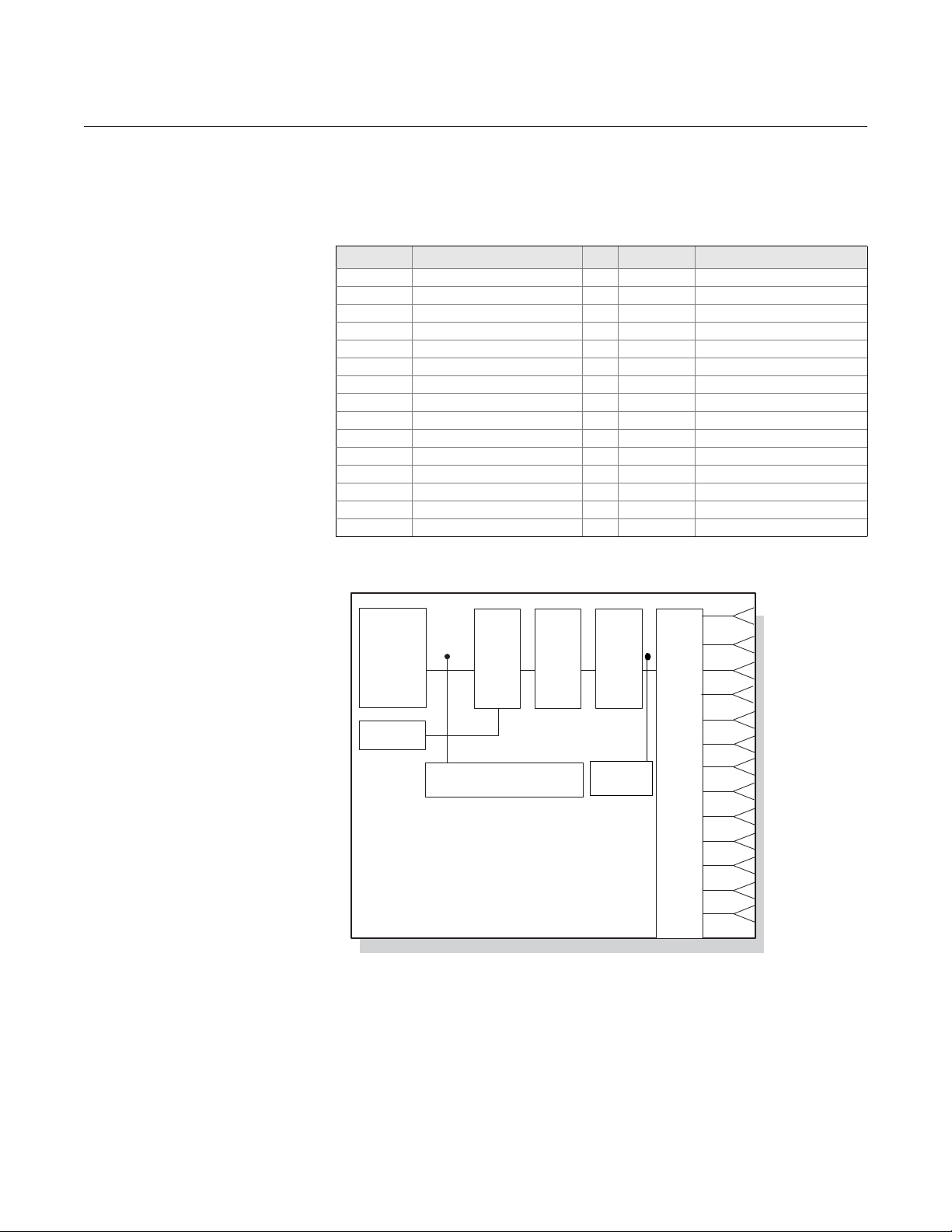
Transducer Blocks The transducer block allows the user to view and manage the channel
information. There is one T ransducer Block for th e eight sensors that contains
specific temperature measurement data, including:
•Sensor Type
• Engineering Units
• Damping
• Temperature Compensation
• Diagnostics
3-15
Page 38
Rosemount 848T
A/D
Signal
Conversion
CJC
Diagnostics
Linearization
Temperature
Compensation
Damping
Units/Ranging
1
2
3
4
5
6
7
8
9
10
11
12
S1
S2
S4
S3
S5
S6
S7
S8
DS1
DS2
13
DS3
DS4
BT
Channel
Channel
Channel
Channel
Channel
Channel
Channel
Channel
Channel
Channel
Channel
Channel
Channel
Measurement
Validation
Table 3-8. Channel Definitions
for the 848T
Reference Manual
00809-0100-4697, Rev EA
October 2011
Transducer Block Channel Definitions
The 848T supports multiple sensor inputs. Each input has a channel assigned
to it allowing an AI or MAI Function Blocks to be linked to that input. The
channels for the 848T are as follows:
Channel Description Channel Description
1 Sensor One 16 Sensor 3 Deviation
2 Sensor Two 17 Sensor 4 Deviation
3 Sensor Three 18 Sensor 5 Deviation
4 Sensor Four 19 Sensor 6 Deviation
5 Sensor Five 20 Sensor 7 Deviation
6 Sensor Six 21 Sensor 8 Deviation
7 Sensor Seven 22 Sensor 1 Rate Change
8 Sensor Eight 23 Sensor 2 Rate Change
9 Differential Sensor 1 24 Sensor 3 Rate Change
10 Differential Sensor 2 25 Sensor 4 Rate Change
11 Differential Sensor 3 26 Sensor 5 Rate Change
12 Differential Sensor 4 27 Sensor 6 Rate Change
13 Body Temperature 28 Sensor 7 Rate Change
14 Sensor 1 Deviation 29 Sensor 8 Rate Change
15 Sensor 2 Deviation
Figure 3-1. Transducer Block
Data Flow
3-16
Transducer Block Errors
The following conditions are reported in the BLOCK_ERR and XD_ERROR
parameters.
Page 39

Reference Manual
00809-0100-4697, Rev EA
October 2011
Table 3-9. Block/Transducer
Error
Rosemount 848T
Condition Number, Name, and Description
0 Other
7 Input failure/process variable has bad status
15 Out of service: The actual mode is out of service
BLOCK_ERR
(1) If BLOCK_ERR is “other,” then see XD_ERROR.
Transducer Block Modes
The transducer block supports two modes of operation as defined by the
MODE_BLK parameter:
Automatic (Auto)
The block outputs reflect the analog input measurement.
Out of Service (OOS)
The block is not processed. Channel outputs are not updated and the
status is set to Bad: Out of Service for each channel. The BLOCK_ERR
parameter shows Out of Service . In this mode, chang es can be made to a ll
configurable parameters. The target mode of a block may be restricted to
one or more of the supported modes.
(1)
Transducer Block Alarm Detection
Alarms are not generated by the transducer block. By correctly handling the
status of the channel values, the down stream block (AI or MAI) will generate
the necessary alarms for the measurement. The error that generated this
alarm can be determined by looking at BLOCK-ERR and XD_ERROR.
Transducer Block Status Handling
Normally, the status of the output channels reflect the status of the
measurement value, the operating condition of the measurement electronics
card, and any active alarm conditions. In a transducer, PV reflects the value
and status quality of the output channels.
Table 3-10. Transducer Block Parameters
Number Parameter Description
0 BLOCK
1 ST_REV The revision level of the static data associated with the function block.
2 TAG_DESC The user description of the intended application of the block.
3 STRATEGY The strategy field can be used to identify grouping of blocks.
4 ALERT_KEY The identification number of the plant unit.
5 MODE_BLK The actual, target, permitted, and normal modes of the block.
6 BLOCK_ERR This parameter reflects the error status associated with the hardware or software
7 UPDATE_EVENT This alert is generated by any change to the static data.
8 BLOCK_ALM The BLOCK-ALM is used for all configuration, hardware, connection failure or system
9 TRANSDUCER_DIRECTORY A directory that specified the number and stating indices of the transducers in the
10 TRANSDUCER_TYPE Identifies the transducer that follows 101 – Standard Temperature with Calibration.
11 XD_ERROR Provides additional error codes related to transducer blocks. For a list of enumeration
components associated with a block. Multiple errors may be shown. For a list of
enumeration values, see FF-890, Block_Err formal model.
problems in the block. The cause of the alert is entered in the subcode field. The first alert
to become active will set the Active status in the Status attribute. As soon as the
Unreported status is cleared by the alert reporting task, another block alert may be
reported without clearing the Active status, if the subcode has changed.
transducer block.
values, see FF-902. Please see tables below for a list of sub-parameters that pertain to
XD_ERROR messages.
3-17
Page 40

Reference Manual
00809-0100-4697, Rev EA
Rosemount 848T
Table 3-10. Transducer Block Parameters
Number Parameter Description
12 COLLECTION_DIRECTORY A directory that specifies the number, starting indices, and DD Item ID’s of the data
collections in each transducer block.
13 SENSOR_1_CONFIG Sensor Configuration Parameters. Please see tables below for a list of sub-parameters
that pertain to Sensor Configuration functions.
14 PRIMARY_VALUE_1 The measured value and status available to the function block.
15 SENSOR_2_CONFIG Sensor Configuration parameters. Please see tables below for a list of sub-parameters
that pertain to Sensor Configuration functions.
16 PRIMARY_VALUE_2 The measured value and status available to the function block.
17 SENSOR_3_CONFIG Sensor Configuration Parameters. Please see tables below for a list of sub-parameters
that pertain to Sensor Configuration functions.
18 PRIMARY_VALUE_3 The measured value and status available to the function block
19 SENSOR_4_CONFIG Sensor Configuration Parameters. Please see tables below for a list of sub-parameters
that pertain to Sensor Configuration functions.
20 PRIMARY_VALUE_4 The measured value and status available to the function block.
21 SENSOR_5_CONFIG Sensor Configuration Parameters. Please see tables below for a list of sub-parameters
that pertain to Sensor Configuration functions.
22 PRIMARY_VALUE_5 The measured value and status available to the function block.
23 SENSOR_6_CONFIG Sensor Configuration Parameters. Please see tables below for a list of sub-parameters
that pertain to Sensor Configuration functions.
24 PRIMARY_VALUE_6 The measured value and status available to the function block.
25 SENSOR_7_CONFIG Sensor Configuration Parameters. Please see tables below for a list of sub-parameters
that pertain to Sensor Configuration functions.
26 PRIMARY_VALUE_7 The measured value and status available to the function block.
27 SENSOR_8_CONFIG Sensor Configuration Parameters. Please see tables below for a list of sub-parameters
that pertain to Sensor Configuration functions.
28 PRIMARY_VALUE_8 The measured value and status available to the function block
29 SENSOR_STATUS Status of each individual sensor. Please see tables below for a list of possible status
messages.
30 SENSOR_CAL Parameter structure to allow for calibration of each sensor. Please see tables below for a
list of sub-parameters that pertain to Sensor Calibration functions.
31 CAL_STATUS Status of the calibration that was previously performed. Please see tables below for a list
of possible Calibration Statuses.
32 ASIC_REJECTION A configurable power line noise rejection setting.
33 BODY_TEMP Body Temperature of the device.
34 BODY_TEMP_RANGE The range of the body temperature including the units index.
35 TB_SUMMARY_STATUS Overall summary status of the sensor transducer. Please see tables below for a list of
possible transducer statuses.
36 DUAL_SENSOR_1_CONFIG Parameter structure to allow for calibration of each differential measurement. Please see
tables below for a list of sub-parameters that pertain to Dual Sensor Calibration functions.
37 DUAL_SENSOR_VALUE_1 The measured value and status available to the function block.
38 DUAL_SENSOR_2_CONFIG Parameter structure to allow for calibration of each differential measurement. Please see
tables below for a list of sub-parameters that pertain to Dual Sensor Calibration functions.
39 DUAL_SENSOR_VALUE_2 The measured value and status available to the function block.
40 DUAL_SENSOR_3_CONFIG Parameter structure to allow for calibration of each differential measurement. Please see
tables below for a list of sub-parameters that pertain to Dual Sensor Calibration functions.
41 DUAL_SENSOR_VALUE_3 The measured value and status available to the function block.
42 DUAL_SENSOR_4_CONFIG Parameter structure to allow for calibration of each differential measurement. Please see
tables below for a list of sub-parameters that pertain to Dual Sensor Calibration functions.
43 DUAL_SENSOR_VALUE_4 The measured value and status available to the function block.
44 DUAL_SENSOR_STATUS Status of each individual differential measurement. Please see tables below for a list of
possible Dual Sensor statuses.
45 VALIDATION_SNSR1_CONFIG Validation configuration parameters. Please see tables below for a list of sub-parameters
that pertain to Validation Configuration functions.
46 VALIDATION_SNSR1_VALUES Validation value parameters. Please see tables below for a list of sub-parameters that
pertain to Validation values.
47 VALIDATION_SNSR2_CONFIG Validation configuration parameters. Please see tables below for a list of sub-parameters
that pertain to Validation Configuration functions.
3-18
October 2011
Page 41

Reference Manual
00809-0100-4697, Rev EA
October 2011
Table 3-10. Transducer Block Parameters
Number Parameter Description
48 VALIDATION_SNSR2_VALUES Validation value parameters. Please see tables below for a list of sub-parameters that
pertain to Validation values.
49 VALIDATION_SNSR3_CONFIG Validation configuration parameters. Please see tables below for a list of sub-parameters
that pertain to Validation Configuration functions.
50 VALIDATION_SNSR3_VALUES Validation value parameters. Please see tables below for a list of sub-parameters that
pertain to Validation values.
51 VALIDATION_SNSR4_CONFIG Validation configuration parameters. Please see tables below for a list of sub-parameters
that pertain to Validation Configuration functions.
52 VALIDATION_SNSR4_VALUES Validation value parameters. Please see tables below for a list of sub-parameters that
pertain to Validation values.
53 VALIDATION_SNSR5_CONFIG Validation configuration parameters. Please see tables below for a list of sub-parameters
that pertain to Validation Configuration functions.
54 VALIDATION_SNSR5_VALUES Validation value parameters. Please see tables below for a list of sub-parameters that
pertain to Validation values.
55 VALIDATION_SNSR6_CONFIG Validation configuration parameters. Please see tables below for a list of sub-parameters
that pertain to Validation Configuration functions.
56 VALIDATION_SNSR6_VALUES Validation value parameters. Please see tables below for a list of sub-parameters that
pertain to Validation values.
57 VALIDATION_SNSR7_CONFIG Validation configuration parameters. Please see tables below for a list of sub-parameters
that pertain to Validation Configuration functions.
58 VALIDATION_SNSR7_VALUES Validation value parameters. Please see tables below for a list of sub-parameters that
pertain to Validation values.
59 VALIDATION_SNSR8_CONFIG Validation configuration parameters. Please see tables below for a list of sub-parameters
that pertain to Validation Configuration functions.
60 VALIDATION_SNSR8_VALUES Validation value parameters. Please see tables below for a list of sub-parameters that
pertain to Validation values.
Rosemount 848T
Changing the Sensor Configuration in the Transducer Block
If the F
OUNDATION fieldbus configuration tool or host system does not support
the use of DD methods for device configuration, the following steps illustrate
how to change the sensor configuration in the transducer block:
1. Set the MODE_BLK.T ARGET to OOS, or set the SENSOR_MODE to
configuration.
2. Set SENSOR_n_CONFIG.SENSOR to the appropriate sensor type,
and then set SENSOR_n_CONFIG.CONNECTION to the appropriate
type and connection.
3. In the Transducer Block, set MODE_BLK.TARGET to AUTO, or set
the SENSOR_MODE to operation.
3-19
Page 42

Rosemount 848T
Transducer Block
Sub-Parameter Tables
Table 3-11. XD_ERROR
Sub-Parameter Structure
Reference Manual
00809-0100-4697, Rev EA
XD ERROR Description
0 No Error
General Error An error has occurred that could not be classified as
17
Calibration Error An error occurred during calibration of the device or a
18
Configuration Error An error occurred during configuration of the device or
19
20 Electronics Failure An electronic component has failed.
22 I/O Failure An I/O failure has occurred.
Data Integrity Error Indicates that data stored within the system may no
23
Software Error The software has detected an error. This could be
24
Algorithm Error The algorithm used in the transducer block produced
25
one of the errors listed below.
calibration error has been detected during operation of
the device.
a configuration error has been detected during
operation of the device.
longer be valid due to non-volatile memory checksum
failure, data verify after write failure, etc.
caused by an improper interrupt service routine, an
arithmetic overflow, a watchdog timer, etc.
an error. This could be due to an overflow, data
reasonableness.
October 2011
Table 3-12. SENSOR_CONFIG
Sub-Parameter Structure
SENSOR CONFIG
STRUCTURE
Parameter Description
SENSOR_MODE Disables or enables a sensor for configuration.
SENSOR_TAG Sensor description.
SERIAL_NUMBER Serial number for the attached sensor.
SENSOR Sensor Type and Connection. MSB is the sensor type and
LSB is the connection.
DAMPING Sampling Interval used to smooth output using a first order
linear filter. A value entered between 0 and the Update_Rate,
will result in a damping value equal to the Update_Rate.
INPUT_TRANSIENT_FILTER Enables or Disables the option for reporting fast changing
sensor inputs without temporary holdoff. 0 = Disable, 1 =
Enabled.
RTD_2_WIRE_OFFSET User entered value for constant lead-wire resistance
correction in a 2-wire RTD and Ohm sensor types.
ENG_UNITS The engineering units used for reporting measured sensor
values.
UPPER_RANGE The upper sensor limit for the selected sensor is displayed
using Units_Index sub parameter.
LOWER_RANGE The lower sensor limit for the selected sensor is displayed
using Units_Index sub parameter.
3-20
Page 43

Reference Manual
00809-0100-4697, Rev EA
October 2011
Rosemount 848T
Table 3-13. SENSOR_STATUS
Sub-Parameter Structure
Table 3-14. SENSOR_CAL
Sub-Parameter Structure
Sensor Status Table
0x00 Active
0x01 Out of Service
0x02 Inactive
0x04 Open
0x08 Short
0x10 Out of Range
0x20 Beyond Limits
0x40 Excess EMF Detected
0x80 Other
SENSOR CALIBRATION
STRUCTURE
Parameter Description
SENSOR_NUMBER The sensor number to calibrate
CALIB_POINT_HI The High calibration point for the selected sensor
CALIB_POINT_LO The Low calibration point for the selected sensor
CALIB_UNIT The engineering units used for calibrating the sensor
The method of the last calibration for sensor
CALIB_METHOD
CALIB_INFO Information regarding the calibration
CALIB_DATE Date that the calibration was completed
CALIB_MIN_SPAN
CALIB_PT_HI_LIMIT The High calibration unit
CALIB_PT_LO_LIMIT The Low calibration unit
103 - factory trim standard calibration
104 - user trim standard calibration
The minimum calibration span value allowed. This minimum span
information is necessary to ensure that when calibration is done,
the two calibrated points are not too close together
Table 3-15. CAL_STATUS
Structure
Table 3-16. Transducer Status
Sub-Parameter Structure
Cal Status
0 No Command Active
1 Command Executing
2 Command Done
3 Command Done: Errors
Transducer Status Table
0x01 A/D Failure
0x02 Sensor Failure
0x04 Dual Sensor Failure
0x08 CJC Degraded
0x10 CJC Failure
0x20 Body Temp Failure
0x40 Sensor Degraded
0x80 Body Temperature Degraded
3-21
Page 44

Rosemount 848T
Reference Manual
00809-0100-4697, Rev EA
October 2011
Table 3-17. DUAL_SENSOR
CONFIG Sub-Parameter
Structure
Table 3-18. DUAL_SENSOR_
STATUS Sub-Parameter
Structure
DUAL SENSOR CONFIG
STRUCTURE
Parameter Description
DUAL_SENSOR_MODE Disables or enables a sensor for configuration
DUAL_SENSOR_TAG Differential description
INPUT_A Sensor to be used in DUAL_SENSOR_CALC
INPUT_B Sensor to be used in DUAL_SENSOR_CALC
Equation used for the dual sensor measurement including:
DUAL_SENSOR_CALC
ENG_UNITS Units used to display sensor parameter
UPPER_RANGE Upper Differential Limit (Input A High - Input B Low)
LOWER_RANGE Lower Differential Limit (Input A Low - Input B High)
Dual Sensor Status Table
0x00 Active
0x01 Out of Service
0x02 Inactive
0x04 Component Sensor Open
0x08 Component Sensor Short
0x10 Component Sensor Out of Range or Degraded
0x20 Component Sensor Out of Limits
0x40 Component Sensor Inactive
0x80 Configuration Error
Not Used, Difference (Input A - Input B), and Absolute
Difference (Input A - Input B)
Table 3-19. Validation Value
Sub-Parameter Structure
Validation Value Sub-Parameter
Structure
Parameter Description
VALIDATION_STATUS
DEVIATION_VALUE Deviation output value
DEVIATION_STATUS Status of the deviation output
RATE_OF_CHANGE_VALUE Rate of change value output
RATE_OF_CHANGE_STATUS Status of Rate of change output
State of the channel specific measurement validation
measurement
3-22
Page 45

Reference Manual
00809-0100-4697, Rev EA
October 2011
Rosemount 848T
Table 3-20. Validation Config
Sub-Parameter Structure
Validation Value Sub-Parameter
Structure
Parameter Description
Activates the measurement validation data gathering
VALIDATION_MODE
SAMPLE_RATE
DEVIATION_LIMIT
DEVIATION_ENG_UNITS Units tied to the deviation output value
DEVIATION_ALERT_SEVERITY
DEVIATION_PCNT_LIM_HYST
RATE_INCREASING_LIMIT Increasing Rate of Change limit set point
RATE_DECREASING_LIMIT Decreasing Rate of Change limit set point
RATE_ENG_UNITS Units tied to the rate of change output value
RATE_ALERT_SEVERITY
RATE_PCNT_LIM_HYST
process
0 = Disable
1 = Enable
Number of seconds per sample used for measurement
validation data collection. This shouldn't exceed 10 seconds
per sample, but currently there are no upper limits.
Sets the limit for the deviation diagnostic. DD limits the upper
range to 10.
Advisory, Maintenance, Failure
0 = Disabled = Does not use the limits, but provides an
output
1 = Advisory = No effect on sensor status, sets advisory
PWA
2 = Maint = Sets sensor status to uncertain, sets
advisory PWA
3 = Failure = Sets sensor status to Bad, sets advisory
PWA
Deviation Hysteresis Limit = (1 DEVIATION_PCNT_LIM_HYST/100) * DEVIATION_LIMIT
Advisory, Maintenance, Failure
0 = Disabled = Does not use the limits, but provides an
output
1 = Advisory = No effect on sensor status, sets advisory
PWA
2 = Maint = Sets sensor status to uncertain, sets
advisory PWA
3 = Failure = Sets sensor status to Bad, sets advisory
PWA
Rate of Change Increasing Hysteresis Limit = (1 RATE_PCNT_LIM_HYST/100) *
RATE_INCREASING_LIMIT
Sensor Calibration in the Sensor Transducer Block
If the F
OUNDATION fieldbus configuration tool or host system does not support
the use of DD methods for device configuration, the following steps illustrate
how to calibrate the sensor from the sensor transducer block:
NOTE:
Active calibrators should not be used in conduction with RTDs on any multiple
input temperature transmitter such as the 848T.
3-23
Page 46

Rosemount 848T
Reference Manual
00809-0100-4697, Rev EA
October 2011
1. Under SENSOR_CALIB, the SENSOR_NUMBER to the number of
the sensor to calibrate.
2. Set CALIB_UNIT to calibration unit.
3. Set CALIB_METHOD to User Trim (seeTable 3-8 on page 3-16 for
valid values).
4. Set the input value of the sensor simulator to be within the range
defined by CALIB_LO_LIMIT and CALIB_HI_LIMIT.
5. Set CALIB_POINT_LO (CALIB_POINT_HI) to the value set at the
sensor simulator.
6. Read CALIB_STATUS and wait until it reads “Command Done”
7. Repeat steps 3 to 5 if performing a two-point trim. Note that the
difference in values between CALIB_POINT_LO and
CALIB_POINT_HI must be greater than CALIB_MIN_SPAN.
3-24
Page 47

Reference Manual
00809-0100-4697, Rev EA
October 2011
Rosemount 848T
Section 4 Operation and Maintenance
Safety Messages . . . . . . . . . . . . . . . . . . . . . . . . . . . . . . . . . page 4-1
Foundation fieldbus Information . . . . . . . . . . . . . . . . . . . . page 4-1
Hardware Maintenance . . . . . . . . . . . . . . . . . . . . . . . . . . . .page 4-3
Troubleshooting . . . . . . . . . . . . . . . . . . . . . . . . . . . . . . . . .page 4-4
SAFETY MESSAGES Instructions and procedures in this section may require special precautions to
ensure the safety of the personnel performing the operations. Infor mation that
potentially raises safety issues is indicated by a warning symbol ( ). Please
refer to the following safety messages before performing an operation
preceded by this symbol.
Warnings
FOUNDATION FIELDBUS INFORMATION
Failure to follow these installation guidelines could result in death or
serious injury.
• Make sure only qualified personnel perform the installation.
Process leaks could result in death or serious injury.
• Do not remove the thermowell while in operation. Removing while in operation may
cause process fluid leaks.
• Install and tighten thermowells and sensors before applying pressure, or process
leakage may result.
Electrical shock could cause death or serious injury.
• If the senor is installed in a high voltage environment and a fault condition or
installation error occurs, high voltage may be present on transmitter leads and
terminals.
• Use extreme caution when making contact with the leads and terminals.
FOUNDATION fieldbus is an all-digital, serial, two-way, multidrop
communication protocol that interconnects devices such as transmitters and
valve controllers. It is a local area network (LAN) for instruments that enable
basic control and I/O to be moved to the field devices. The Model 848T uses
F
OUNDATION fieldbus technology developed and supported by Emerson
Process Management and the other members of the independent Fieldbus
F
OUNDATION.
www.rosemount.com
Page 48

Rosemount 848T
FOUNDATION
Fieldbus
Communications
Stack
Analog-to-Digital
Signal
Conversion
Cold Junction
Input-to-Output
Isolation
Resource
Block
•physical
device
information
Function Blocks
•AI, MAI, and ISEL
Transducer Block
Measurement Sensor
•sensor and differential
temp
•terminal temp.
•sensor configuration
•calibration
•diagnostics
(8 sensors)
T able 4-1. Block Dia gram for the
Rosemount 848T
Reference Manual
00809-0100-4697, Rev EA
October 2011
Commissioning
(Addressing)
To be able to setup, configure, and have it commu nicate with other devices on
a segment, a device must be assigned a permanent address. Unless
requested otherwise, it is assigned a temporary address when shipped from
the factory.
If there are two or more devices on a segment with the same address, the first
device to start up will use the assigned addre ss (ex. Address 20 ). Each of the
other devices will be given one of the four available temporary addresses. If a
temporary address is not available, the device will be unavailable until a
temporary address becomes available.
Use the host system documentation to commission a device and assign a
permanent address.
4-2
Page 49

Reference Manual
00809-0100-4697, Rev EA
October 2011
Rosemount 848T
HARDWARE MAINTENANCE
The 848T has no moving parts and require s a minimal amount of scheduled
maintenance. If a malfunction is suspected, check for an external cause
before performing the diagnostics presented below.
Sensor Check T o determine whether the sensor is causing the malfunction, connect a sensor
calibrator or simulator locally at the transmitter. Consult an Emerson Process
Management representative for additional temperature sensor and accessory
assistance.
Communication/Power
Check
Resetting the
Configuration
(RESTART)
If the transmitter does not communicate or provides an erratic output, check
for adequate voltage to the transmitter. The transmitter requires between 9.0
and 32.0 VDC at the terminals to operate with complete functionality. Check
for wire shorts, open circuits, and multiple grounds.
There are two types of restart s available in the Resource Block. The following
section outlines the usage for each of these. For further information, see
RESTART in Table 3-2 on page 3-6.
Restart Processor (cycling)
Performing a Restart Processor has the same ef fect as removing p ower from
the device and reapplying power.
Restart with Defaults
Performing a Restart with Defaults resets the static parameters for all of the
blocks to their initial state. This is commonly used to change the configur ation
and/or control strategy of the device, including any custom configurations
done at the Rosemount factory.
4-3
Page 50

Rosemount 848T
TROUBLESHOOTING
FOUNDATION fieldbus
Symptom Possible Cause Corrective Action
Device does not show
up in the live list
Device that is acting as
a LAS does not send
out CD
All devices go off live
list and then return
Network configuration parameters
are incorrect
Network address is not in polled
range
Power to the device is below the
9 VDC minimum
Noise on the power /
communication is too high
LAS Scheduler was not
downloaded to the Backup LAS
device
Live list must be reconstructed by
Backup LAS device
Set the network parameters of the LAS (host system) according to the FF
Communications Profile
ST: 8
MRD: 4
DLPDU PhLO: 4
MID: 7
TSC: 4 (1 ms)
T1: 96000 (3 seconds)
T2: 9600000 (300 seconds)
T3: 480000 (15 seconds)
Set first Unpolled Node and Number of UnPolled Nodes so that the device
address is within range
Increase the power to at least 9V
Verify terminators and power conditioners are within specification
Verify that the shield is properly terminated and not grounded at both ends. It is
best to ground the shield at the power conditioner
Ensure that all of the devices that are intended to be a Backup LAS are
marked to receive the LAS schedule
Current link setting and configured links settings are different. Set the current
link setting equal to the configured settings.
Reference Manual
00809-0100-4697, Rev EA
October 2011
Resource Block
Symptom Possible Causes Corrective Action
Mode will not leave
OOS
Block Alarms Will not
work
Target mode not set Set target mode to something other than OOS.
Memory Failure BLOCK_ERR will show the lost NV Data or Lost Static Data bit set. Restart the
device by setting RESTART to Processor. If the block error does not clear, call
the factory.
Features FEATURES_SEL does not have Alerts enabled. Enable the report bit.
Notification LIM_NOTIFY is not high enough. Set equal to MAX_NOTIFY.
Transducer Block Troubleshooting
Symptom Possible Causes Corrective Action
Mode will not leave
OOS
The primary value is
BAD
Target mode not set Set target mode to something other than OOS.
A/D board check sum error The A/D board has a checksum error.
Resource block The actual mode of the Resource block is in OOS. See Resource Block
Diagnostics for corrective action.
Transducer Block The actual mode of the Transducer Block is OOS.
Measurement Look at the SENSOR_STATUS parameter (See Table 3-16 on page 3-21)
4-4
Page 51

Reference Manual
00809-0100-4697, Rev EA
October 2011
Appendix A Reference Data
Functional Specifications . . . . . . . . . . . . . . . . . . . . . . . . . page A-1
Physical Specifications . . . . . . . . . . . . . . . . . . . . . . . . . . . page A-3
Performance Specifications . . . . . . . . . . . . . . . . . . . . . . . page A-4
Function Blocks . . . . . . . . . . . . . . . . . . . . . . . . . . . . . . . . . page A-4
Dimensional Drawings . . . . . . . . . . . . . . . . . . . . . . . . . . . . page A-8
Ordering Information . . . . . . . . . . . . . . . . . . . . . . . . . . . . . page A-12
Rosemount 848T
FUNCTIONAL SPECIFICATIONS
Inputs
Eight independently configurable channels including combinations of 2- and
3-wire RTDs, thermocouples, mV, 2- and 3-wire and ohm inputs.
4–20 mA inputs using optional connector(s).
Outputs
Manchester-encoded digital signal that conforms to IEC 61158 and ISA 50.02.
Status
• 600 Vdc channel to channel isolation
• 10 Vdc channel to channel isolation for all operating conditions with
maximum 150 m. (500 ft) of sensor lead length 18 AWG.
Ambient Temperature Limits
–40 to 185 °F (–40 to 85 °C)
Isolation
Isolation between all sensor channels is rated to 10Vdc over all op erating
conditions. No damage will occur to the device with up to 600 Vdc between
any sensor channel.
Power Supply
Powered over F
The transmitter operates betwee n 9. 0 an d 32 .0 V dc , 22 mA max imu m .
(Transmitter power terminals are rated to 42.4 V dc.)
OUNDATION fieldbus with standard fieldbus power supplies.
(1)
www.rosemount.com
(1) Reference conditions are -40 to 60 °C (-40 to 140 °F) with 30 m. (100 ft) of sensor lead
length 18 AWG wire.
Page 52

Rosemount 848T
Reference Manual
00809-0100-4697, Rev EA
October 2011
Transient Protection
The transient protector (option code T1) helps to prevent damage to the
transmitter from transients induced on the loop wiring by lightning, welding,
heavy electrical equipment, or switch gears. This option is installed at the
factory for the Rosemount 848T and is not intended for field installation.
Update Time
Approximately 1.5 seconds to read all 8 inputs.
Humidity Limits
0–99% non-condensing relative humidity
Turn-on Time
Performance within specifications is achieved in less than 30 seconds after
power is applied to the transmitter.
Alarms
The AI and ISEL function blocks allow the user to configure the alarms to
HI-HI, HI, LO, or LO-LO with a variety of priority levels and hystere sis settings.
Backup Link Active Scheduler (LAS)
The transmitter is classified as a device link master, which means it can
function as a Link Active Scheduler (LAS) if the current link master device fails
or is removed from the segment.
The host or other configuration tool is used to download the schedule for the
application to the link master device. In the absence of a primary link master,
the transmitter will claim the LAS and provide permanent control for the H1
segment.
F
OUNDATION fieldbus Parameters
Schedule Entries 20
Links 30
Virtual Communications Relationships (VCR) 20
A-2
Page 53

Reference Manual
00809-0100-4697, Rev EA
October 2011
Rosemount 848T
PHYSICAL SPECIFICATIONS
Mounting
The Rosemount 848T can be mounted directly onto a DIN rail or it can be
ordered with an optional junction box. When using the optional junction box,
the transmitter can be mounted onto a p an el or a 2- in. pi pe stand (with option
code B6).
Entries for Optional Junction Box
No entry
• Used for custom fittings
Cable Gland
• 9 x M20 nickel-plated brass glands for 7.5–11.9 mm unarmored cable
Conduit
• 5 plugged 0.86-in. diameter holes suitable for installing
Materials of Construction for Optional Junction Box
Junction Box Type Paint
Aluminum Epoxy Resin
Plastic NA
Stainless Steel NA
Aluminum Explosion-proof NA
1
/2-in. NPT fittings.
Weight
Assembly Weight
oz lb kg
Rosemount 848T only 7.5 .47 .208
Aluminum
Plastic
Stainless Steel
Aluminum Explosion-proof 557 34.8 15.5
(1) Add 35.2 oz. (2.2 lb., 0.998 kg) for nickel-plated brass glands
(1)
(1)
(1)
78.2 4.89 2.22
78.2 4.89 2.22
77.0 4.81 2.18
Environmental Ratings
NEMA Type 4X and IP66 with optional junction box. JX3 Explosion-proof
enclosure rated to -4 °F (-20 °C).
A-3
Page 54

Rosemount 848T
Reference Manual
00809-0100-4697, Rev EA
October 2011
FUNCTION BLOCKS
Analog Input (AI)
• Processes the measurement and makes it available on the
fieldbus segment.
• Allows filtering, alarming, and engineering unit changes.
Input Selector (ISEL)
• Used to select between inputs and generate an output using specific
selection strategies such as minimum, maximum, midpoint, or average
temperature.
• Since the temperature value always contains the measurement status, this
block allows the selection to be restricted to the first “good” measurement.
Multiple Analog Input Block (MAI)
• The MAI block allows the eight AI blocks to be multiplexed together so
they serve as one function block on the H1 segment, resulting in greater
network efficiency.
PERFORMANCE SPECIFICATIONS
Stability
• ±0.1% of reading or 0.1 °C (0.18 °F), whichever is greater, for 2 years
for RTDs
• ±0.1% of reading or 0.1 °C (0.18 °F), whichever is greater, for 1 year for
thermocouples.
Self Calibration
The transmitter’s analog-to-digital circuitry automatically self-calibrates for
each temperature update by comparing the dynamic measurement to
extremely stable and accurate internal reference elements.
Vibration Effect
Transmitters are tested to high pipeline vibration specification per IEC
60770-1 1999 with no effect on performance.
Electromagnetic Compatibility Compliance Testing
• Meets the criteria under IEC 61326:2006
• Meets the criteria under European Union Directive 2004/108/EC
A-4
Page 55

Reference Manual
X = Sensor A minimum - Sensor B max.
Y = Sensor A maximum - Sensor B min.
00809-0100-4697, Rev EA
October 2011
Accuracy
Table 1. Input Options/Accuracy
Input Ranges Accuracy Over Range(s)
Sensor Option
2- and 3-Wire RTDs
Pt 50 ( = 0.00391) GOST 6651-94 –200 to 550 –328 to 1022 ± 0.57 ± 1.03
Pt 100 ( = 0.00391) GOST 6651-94 –200 to 550 –328 to 1022 ± 0.28 ± 0.50
Pt 100 ( = 0.00385) IEC 751; = 0.00385, 1995 –200 to 850 –328 to 1562 ± 0.30 ± 0.54
Pt 100 ( = 0.003916) JIS 1604, 1981 –200 to 645 –328 to 1193 ± 0.30 ± 0.54
Pt 200 ( = 0.00385) IEC 751; = 0.00385, 1995 –200 to 850 –328 to 1562 ± 0.54 ± 0.98
Pt 200 ( = 0.003916) JIS 1604; = 0.003916, 1981 –200 to 645 –328 to 1193 ± 0.54 ± 0.98
Pt 500 IEC 751; = 0.00385, 1995 –200 to 850 –328 to 1562 ± 0.38 ± 0.68
Pt 1000 IEC 751; = 0.00385, 1995 –200 to 300 –328 to 572 ± 0.40 ± 0.72
Ni 120 Edison Curve No. 7 –70 to 300 –94 to 572 ± 0.30 ± 0.54
Cu 10 Edison Copper Winding No. 15 –50 to 250 –58 to 482 ± 3.20 ± 5.76
Cu 100 (a=428) GOST 6651-94 -185 to 200 -365 to 392 ± 0.48 ±0.86
Cu 50 (a=428) GOST 6651-94 -185 to 200 -365 to 392 ± 0.96 ±1.73
Cu 100 (a=426) GOST 6651-94 -50 to 200 -122 to 392 ± 0.48 ±0.86
Cu 50 (a=426) GOST 6651-94 -50 to 200 -122 to 392 ± 0.96 ±1.73
Thermocouples—Cold Junction Adds + 0.5 °C to Listed Accuracy
NIST Type B (Accuracy varies
according to input range)
NIST Type E NIST Monograph 175 –200 to 1000 –328 to 1832 ± 0.40 ± 0.72
NIST Type J NIST Monograph 175 –180 to 760 –292 to 1400 ± 0.70 ± 1.26
NIST Type K NIST Monograph 175 –180 to 1372 –292 to 2501 ± 1.00 ± 1.80
NIST Type N NIST Monograph 175 –200 to 1300 –328 to 2372 ± 1.00 ± 1.80
NIST Type R NIST Monograph 175 0 to 1768 32 to 3214 ± 1.50 ± 2.70
NIST Type S NIST Monograph 175 0 to 1768 32 to 3214 ± 1.40 ± 2.52
NIST Type T NIST Monograph 175 –200 to 400 –328 to 752 ± 0.70 ± 1.26
DIN L DIN 43710 –200 to 900 –328 to 1652 ± 0.70 ± 1.26
DIN U DIN 43710 –200 to 600 –328 to 1112 ± 0.70 ± 1.26
w5Re26/W26Re ASTME 988-96 0 to 2000 32 to 3632 ± 1.60 ± 2.88
GOST Type L GOST R 8.585-2001 -200 to 800 -392 to 1472 ± 0.71 ± 1.28
Terminal Temperature -50 to 85 -58 to 185 ±3.50 ± 6.30
Ohm Input 0 to 2000 ohms ± 0.90 ohms
Millivolt Input -10 to 100 mV ± 0.05 mV
1000 mV -10 to 1000 mV ± 1.0 mA
4–20 mA (Rosemount)
4–20 mA (NAMUR)
Multipoint Sensors
(1) Requires the S002 option code.
(2) Multipoint (up to 8 points) thermocouples and RTDs are available f or purchase with t he Rosemount 848T. Input ranges and accuracy for these sensors will
depend on the specific multipoint sensor chosen. For more information, contact your local Emerson representative.
(1)
(1)
(2)
Sensor Reference °C °F °C °F
NIST Monograph 175 100 to 300
301 to 1820
4–20 mA ± 0.01 mA
4–20 mA ± 0.01 mA
Rosemount 848T
212 to 572
573 to 3308
± 6.00
± 1.54
± 10.80
± 2.78
Differential Configuration Notes
Differential capability exists between any two sensor types.
For all differential configurations, the input range is X to Y where
Accuracy for Differential Configurations:
If sensor types are similar (for example, both RTDs or both thermocouples), the accuracy = 1.5 times worst case accuracy of either sensor type.
If sensor types are dissimilar (for example, one RTD and one thermocouple), the accuracy = Sensor 1 Accuracy + Sensor 2 Accuracy.
A-5
Page 56

Reference Manual
00809-0100-4697, Rev EA
Rosemount 848T
Analog Sensors 4–20mA
Two types of 4–20 mA sensors are compatible with the Rosemount 848T. These types must be ordered with the S002 option code complete
with an analog connector kit. The alarm levels, accuracy for each type are listed in Table2.
Table 2. Analog Sensors
Sensor Option
4–20mA (Rosemount
Standard)
4–20mA (NAMUR) 3.8 to 20.5 mA ± 0.01mA
Alarm Levels Accuracy
3.9 to 20.8 mA ± 0.01mA
October 2011
A-6
Page 57

Reference Manual
00809-0100-4697, Rev EA
October 2011
Ambient Temperature Effect
Transmitter may be installed in locations where the ambient temperature is between -40 and 85 °C (-40 and 185 °F)
Table 3. Ambient Temperature Effects
NIST Type Accuracy per 1.0 °C (1.8 °F) Change in Ambient Temperature
RTD
Pt 50 ( = 0.00391)
Pt 100 ( = 0.00391)
Pt 100 ( = 0.00385)
Pt 100 ( = 0.003916)
Pt 200 ( = 0.003916)
Pt 200 ( = 0.00385)
Pt 500
Pt 1000
Cu 10
Cu 100 (a=428)
Cu 50 (a=428)
Cu 100 (a=426)
Cu 50 (a=426)
Ni 120
Thermocouple (R = the value of the reading)
Type B
Type E
Type J, DIN Type L
Type K
Type N
Type R, Type S
Type T, DIN Type U
GOST Type L
Millivolt
2- and 3-wire Ohm
4–20 mA (Rosemount)
4-20 mA (NAMUR)
(1) Change in ambient is in reference to the calibration temperature of the transmitter (20 °C (68 °F) typical from the factory).
• 0.004 °C (0.0072 °F)
• 0.002 °C (0.0036 °F)
• 0.003 °C (0.0054 °F)
• 0.003 °C (0.0054 °F)
• 0.004 °C (0.0072 °F)
• 0.004 °C (0.0072 °F)
• 0.003 °C (0.0054 °F)
• 0.003 °C (0.0054 °F)
• 0.03 °C (0.054 °F)
• 0.002 °C (0.0036 °F)
• 0.004 °C (.0072 °F)
• 0.002 °C (0.0036 °F)
• 0.004 °C (.0072 °F)
• 0.003 °C (0.0054 °F)
• 0.014 °C
• 0.032 °C - (0.0025% of (R - 300))
• 0.054 °C - (0.011% of (R - 100))
• 0.005 °C + (0.00043% of R) •All
• 0.0054 °C + (0.00029% of R)
• 0.0054 °C + (0.0025% of |R|)
• 0.0061 °C + (0.00054% of R)
• 0.0061 °C + (0.0025% of |R|)
• 0.0068 °C + (0.00036% of R) •All
• 0.016 °C
• 0.023 °C - (0.0036% of R)
• 0.0064 °C
• 0.0064 °C + (0.0043% of |R|)
• 0.007 °C
• 0.007 °C + (0.003% of IRI)
• 0.0005 mV
• 0.0084 ohms
• 0.0001 mA
• 0.0001 mA
(1)
Rosemount 848T
C
Temperature Range (°C)
NA
NA
NA
NA
NA
NA
NA
NA
NA
NA
NA
NA
NA
NA
•R 1000
•300 R < 1000
•100 R < 300
•R 0
•R 0
•R 0
•R 0
•R 200
•R 200
•R 0
•R 0
•R 0
•R 0
NA
NA
NA
NA
A-7
Page 58

Rosemount 848T
0.3020.03
2
+ 0.30C=
Top View
3-D View
Side View
Security Switch
Simulation Switch
6.7
(170)
3.7
(93)
1.7
(43)
Removable Wiring
Connection
Reference Manual
00809-0100-4697, Rev EA
October 2011
Ambient Temperature Notes
Examples:
When using a Pt 100 ( = 0.00385) sensor input at 30 °C am b ien t
temperature:
• Digital Temperature Effects: 0.003 °C x (30 - 20) = .03 °C
• Worst Case Error: Digital + Digital Temperature Effects = 0.3 °C + .03 °C =
.33 °C
• Total Probable Error
DIMENSIONAL DRAWINGS
Junction Boxes with no entries (option codes JP1, JA1, and JS1)– external
dimensions are the same as those outlined for the other junction box
materials in this section.
Rosemount 848T
A-8
Dimensions are in inches (millimeters)
Page 59

Reference Manual
Top View 3-D View
Front View
Side View
4.41 (112)
10.24 (260)
1.73 (44)
2.44 (62)
2.28 (58)
1.10 (28)
7.84 (199.2)
6.30 (160)
3.78 (96)
1.57 (40)
Ground Screw
Top View
3-D View
Front View
Side View
9.91 (231)
7.7 (196)
4.0 (102)
1.8 (47)
1.2 (30)
2.4 (62)
1.1 (28)
1.8 (46)
1.73 (44)
6.61 (168)
9.14 (232.2)
Ground Screw
7.72 (196)
00809-0100-4697, Rev EA
October 2011
Aluminum/Plastic Junction Box—Cable Gland (option codes JA2 and JP2)
Rosemount 848T
Dimensions are in inches (millimeters)
Stainless Steel Junction Box—Cable Gland (option code JS2)
Dimensions are in inches (millimeters)
A-9
Page 60

Rosemount 848T
Top View
3-D View
Front View Side View
10.2 (260)
157 (40)
2.44 (62)
3.5 (89)
1.7 (42)
10.2 (260)
Five Plugged 0.86-in. diameter
holes suitable for installing
1
/2-in.
NPT fittings
Top View
3-D View
Front View
Side View
9.1 (231)
7.7 (196)
2.8 (70)
1.2 (30)
1.4 (35)
1.1 (27)
2.4 (62)
1.6 (42)
0.06 (1.5)
1.8 (4.7)
4.0 (102)
Ground Screw
Five Plugged 0.86-in. diameter holes suitable for installing 1/2-in. NPT fittings
Aluminum/Plastic Junction Box—Conduit Entry (option codes JA3 and JP3)
Reference Manual
00809-0100-4697, Rev EA
October 2011
A-10
Dimensions are in inches (millimeters)
Stainless Steel Junction Box—Conduit Entry (option code JS3)
Dimensions are in inches (millimeters)
Page 61

Reference Manual
5.1
(130)
10.2
(260)
6.6 (167) fully
assembled
4.5
(114)
7.5 (190) fully
assembled
00809-0100-4697, Rev EA
October 2011
Mounting Options
Rosemount 848T
Aluminum/Plastic Junction Box
(styles JA and JP)
Front View Side View Front View Side View
Dimensions are in inches (millimeters)
Aluminum/Plastic Junction Box
Mounted on a Vertical Pipe
Stainless Steel Junction Box
(style JS)
Stainless Steel Junction Box
Mounted on a Vertical Pipe
A-11
Page 62

Reference Manual
00809-0100-4697, Rev EA
Rosemount 848T
October 2011
ORDERING INFORMATION
Table A-1. Rosemount 848T FOUNDATION fieldbus Ordering Information
★ The Standard offering represents the most common options. The starred options (★) should be selected for best delivery.
__The Expanded offering is subject to additional delivery lead time.
Model Product Description
848T High Density Temperature Measurement Family
Transmitter Output
Standard Standard
F FOUNDATION fieldbus digital signal (includes AI, MAI, and ISEL function blocks, and Backup Link Active
Scheduler)
Rosemount
Product Certifications
Standard Standard
I1 ATEX Intrinsic Safety No ★
I3 NEPSI Intrinsic Safety No ★
I4 TIIS Intrinsically Safety (FISCO) Type '1a’ No ★
H4 TIIS Intrinsic Safety (FISCO) Type '1b’ No ★
(2)
I5
I6
I7 IECEx Intrinsic Safety No ★
IA ATEX FISCO Intrinsic Safety No ★
IE FM FISCO Intrinsically Safe No ★
IF
IG IECEx FISCO (Intrinsic Safety) No ★
N1 ATEX Type n (enclosure required) Yes ★
N5 FM Class I, Division 2, and Dust Ignition-proof (enclosure required) Yes ★
N6 CSA Class I, Division 2 No ★
N7 IECEx Type n (enclosure required) Yes ★
NC ATEX Type n Component (Ex nA nL) No
ND ATEX Dust (enclosure required) Yes ★
NJ IECEx Type n Component (Ex nA nL) No
NK FM Class 1, Division 2 No ★
NA No Approval No ★
Expanded
E6 CSA Explosion-proof, Dust Ignition-proof, Division 2 (JX3 enclosure required) Yes
FM Intrinsically Safe No ★
(2)
CSA Intrinsically Safe No ★
(2)
CSA FISCO Intrinsically Safe, Division 2 No ★
(1)
Junction
Box required?
(3)
(3)
(4)
★
★
★
Options (Include with selected model number)
Input Types
Standard Standard
S001 RTD, Thermocouple, mV, Ohm Inputs ★
(5)
S002
PlantWeb Advanced Diagnostics
Standard Standard
D04 Measurement Validation Diagnostic ★
Transient Protection
Standard Standard
T1 Integral Transient Protector ★
Mounting Bracket
B6 Mounting Bracket for 2-in. pipe mounting – SST bracket and bolts ★
RTDs, Thermocouple, mV, Ohm and 4–20 mA Inputs ★
A-12
Page 63

Reference Manual
00809-0100-4697, Rev EA
October 2011
Table A-1. Rosemount 848T FOUNDATION fieldbus Ordering Information
★ The Standard offering represents the most common options. The starred options (★) should be selected for best delivery.
__The Expanded offering is subject to additional delivery lead time.
Enclosure Options
Standard Standard
JP1 Plastic Junction Box; No Entries ★
JP2 Plastic Box, Cable Glands (9 x M20 nickel-plated brass glands for 7.5–11.9 mm unarmored cable) ★
JP3 Plastic Box, Conduit Entries (5 Plugged Holes, suitable for installing 1/2-in. NPT fittings) ★
JA1 Aluminum Junction Box; No Entries ★
JA2 Aluminum Cable Glands (9 x M20 nickel-plated brass glands for 7.5–11.9 mm unarmored cable) ★
JA3 Aluminum Conduit Entries (5 Plugged Holes, suitable for installing 1/2-in. NPT fittings) ★
JS1 Stainless Steel Junction Box; No Entries ★
JS2 Stainless Steel Box, Cable Glands (9 x M20 nickel-plated brass glands for 7.5–11.9 mm unarmored cable) ★
JS3 Stainless Steel Box, Conduit Entries (5 Plugged Holes, suitable for installing 1/2-in. NPT fittings) ★
(6)
JX3
Software Configuration
Standard Standard
C1 Custom Configuration of Date, Descriptor, Message and Wireless Parameters (Requires CDS with Order) ★
Line Filter
Standard Standard
F5 50 Hz Line Voltage Filter ★
Calibration Certificate
Standard Standard
Q4 Calibration Certificate (3-Point Calibration) ★
Shipboard Certification
Standard Standard
SBS American Bureau of Shipping (ABS) Type Approval ★
SLL Lloyd's Register (LR) Type Approval ★
Special Temperature Test
Expanded
LT Test to -60 °F (-51.1 °C)
Conduit Electrical Connector
Standard Standard
GE
GM
Typical Model Number: 848T F I5 S001 T1 B6 JA2
(1) Consult factory for availability.
(2) Available only with S001 option.
(3) The Rosemount 848T ordered with component approval is not approved as a stand-alone unit. Additional system certification is required.
(4) Enclosure Option JX3 must be ordered with Product Certification Code E6. (O-ring for the JX3 enclosure rated to -20 °C).
(5) S002 is only available with Product Certification N5, N6, N1, NC, NK, and NA.
(6) JX3 Explosion-proof enclosure rated to -4 °F (-20 °C).
(7) Available with no approval or Intrinsically Safe approvals only. For FM Intrinsically Safe (option code I5), install in accordance with Rosemount drawing
00848-4402.
Explosion-proof Box, Conduit Entries (4 Plugged Holes, suitable for installing 1/2-in. NPT fittings) ★
(7)
M12, 4-pin, Male Connector (eurofast®) ★
(7)
A size Mini, 4-pin, Male Connector (minifast®) ★
Rosemount 848T
A-13
Page 64

Rosemount 848T
Reference Manual
00809-0100-4697, Rev EA
October 2011
A-14
Page 65

Reference Manual
00809-0100-4697, Rev EA
October 2011
Appendix B Product Certificates
Hazardous Locations Certificates . . . . . . . . . . . . . . . . . . . page B-1
Intrinsically Safe and Non-Incendive Installations . . . . . page B-11
Installation Drawings . . . . . . . . . . . . . . . . . . . . . . . . . . . . . page B-12
HAZARDOUS LOCATIONS CERTIFICATES
Rosemount 848T
North American
Approvals
Factory Mutual (FM) Approvals
I5 Intrinsically Safe and Non-Incendive
Intrinsically Safe for use in Class I, Division 1, Groups A, B, C, D; when
installed per Rosemount drawing 00848-4404.
Temperature Code:
T4 (T
= –40 to 60 °C)
amb
Non-Incendive for use in Class I, Division 2, Groups A, B, C, D (suitable
for use with Non-Incendive field wiring) when installed in accordance with
Rosemount Drawing 00848-4404.
Temperature Code:
T4A (T
T5 (T
= -40 to 85 °C)
amb
= -40 to 70 °C)
amb
Rosemount Enclosure Required.
Indoor Hazardous (Classified) Locations.
Table B-1. FM Approved Entity Parameters
Power/Bus Sensor
V
= 30 V
max
I
= 300 mA
max
Pi = 1.3 W
Ci = 2.1 nF
Li = 0
(1) Entity parameters apply to entire device, not individual sensor channels.
VOC = 12.5 V
ISC= 4.8 mA
Po = 15 mW
CA = 1.2 F
LA = 1 H
(1)
www.rosemount.com
Table B-2. Entity Parameters for Non Incendive Field Wiring
Power/Bus Sensor
V
= 42.4 V VOC = 12.5 V
max
Ci = 2.1nF I
Li = 0 Po = 15 mW
(1) Entity parameters apply to entire device, not individual sensor channel.
(1)
= 4.8 mA
SC
CA = 1.2 F
LA = 1 H
Page 66

Rosemount 848T
Reference Manual
00809-0100-4697, Rev EA
October 2011
IE FISCO (Fieldbus Intrinsically Safe Concept) Intrinsic Safety
Intrinsically safe for use in Class I, Division 1, Groups A, B, C, D; when
installed in accordance with Rosemount Drawing 00848-4404.
Temperature Code:
T4 (T
Non-incendive for use in Class I, Division 2, Groups A, B, C, D (suitable
for use with non-incendive field wiring); when installed in accordance
with Rosemount Drawing 00848-4404.
Temperature Code:
T4A (T
T5 (T
Table B-3. Entity Parameters
Power/Bus Sensor
V
= 17.5 V VOC = 12.5 V
max
I
= 380 mA I
max
Pi = 5.32 W Po = 15 mW
Ci = 2.1nF CA = 1.2 F
Li = 0 LA = 1 H
(1) Entity parameters apply to entire device, not individual sensor channels.
= –40 to 60 °C)
amb
= –40 to 85 °C)
amb
= –40 to 70 °C)
amb
= 4.8 mA
SC
(1)
N5 Dust Ignition-Proof
For use in Class II, III, Division 1, Groups E, F, G. Class I, Division 2,
Groups A, B, C, D;
Non-incendive for Class 1, Division 2, Groups A, B, C, D when installed
to Rosemount Control Drawing 00848-4404.
Rosemount Enclosure Required.
Valid with both S001 and S002 options.
Temperature Code:
T4A (T
T5 (T
= –40 to 85 °C)
amb
= –40 to 70 °C)
amb
NK Non-Incendive for use in Class I, Division 2, Groups A, B, C, D (suitable
for use with Non-Incendive field wiring) when installed in accordance with
Rosemount Drawing 00848-4404.
Temperature Code:
T4A (T
T5 (T
= -40 to 85 °C)
amb
= -40 to 70 °C)
amb
Rosemount Enclosure Required.
Indoor Hazardous (Classified) Locations.
Table B-4. FM Approved Entity Parameters
Power/Bus Sensor
V
= 42.4 V VOC = 12.5 V
max
Ci = 2.1 F I
Li = 0 H Po = 15 mW
(1) Intrinsically safe and non-incendive parameters.
(1)
= 4.8 mA
SC
CA = 1.2 F
LA = 1 H
B-2
Page 67

Reference Manual
00809-0100-4697, Rev EA
October 2011
Rosemount 848T
Canadian Standards Association (CSA) Certifications
E6 Explosion-Proof and Dust Ignition-Proof
Class I, Division 1, Groups B, C, and D.
Class II, Division 1, Groups E, F, and G.
Class III
Must be installed in enclosure option JX3.
Install per drawing 00848-1041.
Conduit seal not required.
Suitable for use in Class I, Division 2, Groups A, B, C, D. when installed
per Rosemount drawing 00848-4405.
Temperature Code:
T3C = (– 50 T
Must be installed in a suitable enclosure as determined acceptable by
the local inspection authority.
I6 Intrinsically Safe, Division 2
For use in Class I, Division 1, Groups A, B, C, D; when installed per
Rosemount drawing 00848-4405.
Temperature Code:
T3C (T
= –50 to 60 °C)
amb
Suitable for Class I, Division 2, Groups A, B, C, D. Rated 42.4 VDC max.
Not valid with S002 option.
60 °C)
amb
Table B-5. CSA Approved Entity Parameters
= 4.8 mA
SC
LA = 1 H
(1)
Power/Bus Sensor
V
= 30 V VOC = 12.5 V
max
I
= 300 mA I
max
Ci = 2.1nF Po = 15 mW
Li = 0 CA = 1.2 F
(1) Entity parameters apply to entire device, not individual sensor channels.
IF FISCO (Intrinsically Safe)
For use in Class I, Division 1, Groups A, B, C, D; when installed per
Rosemount drawing 00848-4405.
Temperature Code:
T3C (T
= –50 to 60 °C)
amb
Suitable for Class I, Division 2, Groups A, B, C, D. Rated 42.4 VDC max.
Not valid with S002 option.
Table B-6. CSA Approved Entity Parameters
= 4.8 mA
SC
(1)
Power/Bus Sensor
Ui = 17.5 V VOC = 12.5 V
Ii = 380 mA I
Pi = 5.32 W Po = 15 mW
Ci = 2.1nF Ca = 1.2 F
Li = 0 La = 1 H
(1) Entity parameters apply to entire device, not individual sensor channels.
B-3
Page 68

Rosemount 848T
N6 Class I, Division 2
Suitable for use in Class I, Division 2, Groups A, B, C, D. when installed
per Rosemount drawing 00848-4405.
Temperature Code:
T3C = (–50 T
Must be installed in a suitable enclosure as determined acceptable by
the local inspection authority.
European Approvals ATEX Certifications
I1 Intrinsic Safety
Certification Number: Baseefa09ATEX0093X
ATEX Marking II 1 G
Ex ia IIC T4 (T
1180
Table B-7. ATEX Approved Entity Parameters
Power/Bus Sensor
Ui = 30 V Uo = 12.5 V
Ii = 300 mA Io = 4.8 mA
Pi = 1.3 W Po = 15 mW
Ci = 0 Ci = 1.2 F
Li = 0 Li = 1 H
60 °C)
a
= –50 to 60 °C)
amb
Reference Manual
00809-0100-4697, Rev EA
October 2011
Special Conditions for Safe Use (x):
1. This apparatus must be installed in an enclosure which affords it a
degree of protection of at least IP20. Non-metallic enclosures must
have a surface resistance of less than 1Gohm. Light alloy or
zirconium enclosures must be protected from impact and friction
when installed.
2. The apparatus will not meet the 500V rms isolation test required by
Clause 6.4.12 on EN 60079-1 1:2007. This must be t aken into account
when installing the apparatus.
IA FISCO (Fieldbus Intrinsically Safe Concept) Intrinsic Safety
Certificate Number: BASEEFA09ATEX0093X
ATEX Marking II 1 G
Ex ia IIC T4 (T
= –50 to 60 °C)
amb
1180
Table B-8. ATEX Approved Entity Parameters
Power/Bus Sensor
Ui = 17.5 V Uo = 12.5 V
Ii = 380 mA Io = 4.8 mA
Pi = 5.32 W Po = 15 mW
Ci = 0 Ci = 1.2 F
Li = 0 Li = 1 H
B-4
Page 69

Reference Manual
00809-0100-4697, Rev EA
October 2011
Rosemount 848T
Special Conditions for Safe Use (x):
1. This apparatus must be installed in an enclosure which affords it a
degree of protection of at least IP20. Non-metallic enclosures must
have a surface resistance of less than 1Gohm. Light alloy or
zirconium enclosures must be protected from impact and friction
when installed.
2. The apparatus will not meet the 500V rms isolation test required by
Clause 6.4.12 on EN 60079-1 1:2007. This must be t aken into account
when installing the apparatus.
NE ATEX TYPE ‘n’ APPROVAL
Certification Number: BASEFFA09ATEX0095X
ATEX Marking II 3 G
Ex nA nL IIC T5 (T
Table B-9. Baseefa Approved Entity Parameters
Power/Bus Sensor
Ui = 42.4 Vdc Uo = 5 Vdc
Ci = 0 Io = 2.5 mA
Li = 0 Co = 1000 F
= –40 to 65 °C)
amb
Lo = 1000 mH
Special Conditions for Safe Use (x):
1. Provisions shall be made, external to the apparatus to prevent the
rated voltage (42.4 Vdc) from being exceeded by transient
disturbances of more than 40%.
2. The ambient temperature range of use shall be the most restrictive of
the apparatus, cable gland, or blanking plug.
NOTE:
NE is valid with S001 Input Type ONLY
N1 ATEX Type n
Certification Number: Baseefa09ATEX0095X
ATEX Marking II 3 G
Ex nL IIC T5 (T
= –40 to 65 °C)
amb
Table B-10. Entity Parameters
Power/Bus Sensor
Ui = 42.4 Vdc Uo = 12.5 Vdc
Ci = 0 Io = 4.8 mA
Li = 0 Po = 15 mW
Co = 1.2 F
Lo = 1 H
B-5
Page 70

Rosemount 848T
Reference Manual
00809-0100-4697, Rev EA
October 2011
Special Conditions for Safe Use (x):
1. Provisions shall be made, external to the apparatus, to prevent the
rated voltage of the apparatus supply is not exceeded by transient
disturbances of more than 40%
2. The electrical circuit is connected directly to earth; this must be taken
into account when installing the apparatus.
NC ATEX Type n Component
Certification Number: Baseefa09ATEX0094U
ATEX Marking II 3 G
Ex nA nL IIC T4 (T
Ex nA nL IIC T5 (T
Special Conditions for Safe Use (x):
1. The component must be housed in a suitable certified enclosure that
provides a degree of protection of at least IP 54 and me ets the
relevant material and environmental requireme nts of EN 60079-0 ,
and EN-60079-15.
2. Provisions shall be made, external to the apparatus, to prevent the
rated voltage (42.4 VDC) being exceeded by transient disturbances
of more than 40%.
3. The electrical circuit is connected directly to earth: this must be taken
into account when installing the apparatus.
= –50 to 85 °C)
amb
= –50 to 70 °C)
amb
NOTE
NC is valid with S001 Input Type ONLY
ND ATEX Dust Ignition Proof
Certification Number: BAS01ATEX1315X
ATEX Marking II 1 D
T90C (T
= – 40 to 65 °C) IP66
amb
Special Conditions for Safe Use (x):
1. The user must ensure that the maximum rated voltage and current
(42.4 volts, 22 mA, DC) are not exceeded. All connections to other
apparatus or associated apparatus shall have control over this
voltage and current equivalent to a category “ib” circuit according to
EN50020.
2. Component approved EEx e cable entries must be used which
maintain the ingress protection of the enclosure to at least IP66.
3. Any unused cable entry holes must be filled with component
approved EEx e blanking plugs.
4. The ambient temperature range of use shall be the most restrictive of
the apparatus, cable gland, or blanking plug.
Table B-11. Baseefa Approved Entity Parameters
Power/Bus Sensor
Ui = 42.4 V Uo = 5V dc
Ci = 0 Io = 2.5 mA
Li = 0 Co = 1000 F
Lo = 1 H
B-6
Page 71

Reference Manual
00809-0100-4697, Rev EA
October 2011
Rosemount 848T
Special Conditions of Safe Use (x):
1. The component must be housed in a suitable certified enclosure.
2. Provisions shall be made, exter nal to the apparatus, to prevent the
rated voltage (42.2 V dc) being exceeded b y transient disturbances of
more than 40%.
IECEx Certifications
I7 IECEx Intrinsic Safety
Certificate No.: IECExBAS09.0030X
Ex ia IIC T4 (T
Table B-12. IECEx Approved Entity Parameters
Power/Bus Sensor
Ui = 30 V Uo = 12.5 V
Ii = 300 mA Io = 4.8 mA
Pi = 1.3 W Po = 15 mW
Ci = 2.1 F Ci = 1.2 F
Li = 0 Li = 1 H
= –50 to 60 °C)
amb
Special Conditions of Safe Use (x):
1. The apparatus must be installed in an enclosure that provides a
degree of protection of at least IP20. Non-metallic enclosures must be
suitable to prevent electrostatic hazards and light alloy or zirconium
enclosures must be protected from impact and friction when installed.
2. The apparatus is not capable of withstanding the 500V isolation test
required by IEC 60079-11: 2006 clause 6.3.12. This must be taken
into account when installing the apparatus.
IG IECEx FISCO
Certificate No.: IECExBAS09.0030X
Ex ia IIC T4 (T
= – 50 to 60 °C)
amb
Table B-13. IECEx Approved Entity Parameters
Power/Bus Sensor
Ui =17.5 Vdc Uo = 12.5 Vdc
Ii = 380 mA Io = 4.8 mA
Pi = 5.32 W Po = 15 mW
Ci = 2.1 F Ci = 1.2 F
Li = 0 Li = 1 H
Special Conditions of Safe Use (x):
1. The apparatus must be installed in an enclosure that provides a
degree of protection of at least IP20. Non-metallic enclosures must be
suitable to prevent electrostatic hazards and light alloy or zirconium
enclosures must be protected from impact and friction when installed.
2. The apparatus is not capable of withstanding the 500V isolation test
required by IEC 60079-11: 2006 clause 6.3.12. This must be taken
into account when installing the apparatus.
B-7
Page 72

Rosemount 848T
Reference Manual
00809-0100-4697, Rev EA
October 2011
N7 IECEx Type n Approval
Certificate No.” IECExBAS09.0032X
Ex Na nL IIC T5 (T
NOTE:
N7 is valid with S001 and S002 Input Types
Table B-14. IECEx Approved Entity Parameters
Power/Bus Sensor
Ui = 42.4 Vdc Uo = 5 Vdc
Ci = 0 Io = 2.5 mA
Li = 0 Co = 1000 F
Special Conditions of Safe Use:
1. The component must be housed in a suitable component certified
enclosure that provides a degree of protection of at least IP54 and
meets the relevant material and environmental requirements of IEC
60079-0: 2004 & IEC 60079-15: 2005.
2. Provision must be made, external to the component, to ensure the
rated voltage of the component supply is not exceeded by transient
disturbances of more than 40%.
3. The electrical circuit is connected directly to earth; this must be taken
into account when installing the component.
= – 40 to 65 °C)
amb
Lo = 1000 mH
B-8
NJ IECEx Type n COMPONENT Approval
Certification Number: IECExBAS09.0031U
EEx nA nL IIC T4 (T
EEx nA nL IIC T5 (T
= -50 to 85 °C)
amb
= -50 to 70 °C)
amb
NOTE:
NJ is valid with S001 and S002 Input Types
Table B-15. IECEx Approved Entity Parameters
Power/Bus Sensor
Ui = 42.4 Vdc Uo = 5 Vdc
Ci = 0 Io = 2.5 mA
Li = 0 Co = 1000 F
Lo = 1000 mH
Special Conditions of Safe Use:
1. The component must be housed in a suitable component certified
enclosure that provides a degree of protection of at least IP54 and
meets the relevant material and environmental requirements of IEC
60079-0: 2004 & IEC 60079-15: 2005.
2. Provision must be made, external to the component, to ensure the
rated voltage of the component supply is not exceeded by transient
disturbances of more than 40%.
3. The electrical circuit is connected directly to earth; this must be taken
into account when installing the component.
Page 73

Reference Manual
00809-0100-4697, Rev EA
October 2011
Rosemount 848T
China (NEPSI)Certifications
I3 Intrinsic Safety
Ex ia IIC T4
Certification Number: GYJ111365X
Special Conditions for Safe Use (x):
2.1. Only when temperature transmitter is installed in IP
20(GB4208-2008) housing, it could be used in hazardous location.
The metallic housing should observe the requirements of
GB3836.1-2000 Clause 8. The non-metallic housing should observe
the requirements of GB3836.1-2000 Clause 7.3. This apparatus is
not capable of withstanding the 500V rms insulation test required by
Clause 6.4.12 of GB3836.4-2000.
2.2. The ambient temperature range is:
Output T code Ambient temperature
F T4 -50 °C < Ta < + 60 °C
2.3. Parameters:
Terminals of power/loop (1-2):
Maximum
Output
F (FISCO) 17.5 380 5.32 2.1 0
Output Voltage:
U
(V)
o
F 30 300 1.3 2.1 0
Maximum
Output Current:
I
(mA)
o
Maximum
Output Power:
P
(mW)
o
Maximum external
Co (F) Lo (H)
parameters:
NOTE
Non-FISCO parameters listed above must be derived from a linear supply
with a resistance limited output.
Terminals of sensor:
Maximum
Output Terminals
F 1-8 12.5 4.8 15 1.2 1
Output Voltage:
U
(V)
o
Maximum
Output Current:
I
(mA)
o
Maximum
Output Power:
P
(mW)
o
Maximum external
parameters:
Co (F) Lo (H)
2.4. The product complies to the requirements for FISCO field devices
specified in IEC60079-27: 2008. For the connection of an intrinsically
safe circuit in accordance FISCO model, FISCO parameters of this
product are as above.
2.5. The product should be used with Ex-certified associated apparatus to
establish explosion protection system that can be used in explosive
gas atmospheres. Wiring and terminals should comply with the
instruction manual of the product and associated apparatus.
2.6. The cables between this product and associated apparatus should be
shielded cables (the cables must have insulated shield). The shielded
cable has to be grounded reliably in non-hazardous area.
B-9
Page 74

Rosemount 848T
Reference Manual
00809-0100-4697, Rev EA
October 2011
2.7. End users are not permitted to change any component’s insides, but
to settle the problem, in conjunction with manufacturer to avoid
damage to the product.
2.8. During installation, use and maintenance of this product, observe
following standards:
GB3836.13-1997 "Electrical apparatus for explosive gas
atmospheres Part 13: Repair and overhaul for apparatus used in
explosive gas atmospheres."
GB3836.15-2000 "Electrical apparatus for explosive gas atmosp heres
Part 15: Electrical installations in hazardous area (other than mines)."
GB3836.16-2006 "Electrical apparatus for explosive gas atmospheres
Part 16: Inspection and maintenance of electrical installation (other
than mines)."
GB50257-1996 "Code for construction and acceptance of electric
device for explosion atmospheres and fire hazard electrical
equipment installation engineering."
Japanese Certifications
I4 TISS Intrinsic Safety FISCO Type ‘1a’
Ex ia IIC T4
Certification Number: TC19713
H4 TISS Intrinsic Safety FISCO Type ‘1b’
Ex ia IIB T4
Certification Number: TC19714
B-10
Page 75

Reference Manual
848T without
enclosure
Approved I.S. or
FISCO barrier
848T with enclosure
Non-approved
power supply
848T with enclosure
Non-approved
power supply
848T without enclosure
Approved
non-incendive
power supply
or barrier
Non-approved
power supply
848T with enclosure
Standard cable
Division 2 wiring
00809-0100-4697, Rev EA
October 2011
INTRINSICALLY SAFE AND NON-INCENDIVE INSTALLATIONS
Rosemount 848T
Zone 2
(category 3)
Approval Division 2 Division 1
Safe Area
Zone 1
(category 2)
GAS INSTALLATIONS
I5, I6, I1,
I7, IE, IA
N1, N7
N5
I5, I6, IE
Zone 0
(category 1)
DUST INSTALLATIONS
N5, ND
B-11
Page 76

Rosemount 848T
Reference Manual
00809-0100-4697, Rev EA
October 2011
INSTALLATION DRAWINGS
The installation guidelines presented by the drawings must be followed in
order to maintain certified ratings for installed transmitters.
Rosemount Drawing 00848-4404, 3 Sheets
Factory Mutual Intrinsic Safety/ FISCO Installation Drawing
Rosemount Drawing 00848-4405, 2 Sheets
Canadian Standards Association Intrinsic Safety/FISCO Installation Drawing
B-12
Page 77

Reference Manual
Electronic Master – PRINTED COPIES ARE UNCONTROLLED – Rosemount Proprietary
00809-0100-4697, Rev EA
October 2011
Figure B-1. FM Intrinsic Safety/ FISCO
Rosemount 848T
B-13
Page 78

Rosemount 848T
Electronic Master – PRINTED COPIES ARE UNCONTROLLED – Rosemount Proprietary
Reference Manual
00809-0100-4697, Rev EA
October 2011
B-14
Page 79

Reference Manual
Electronic Master – PRINTED COPIES ARE UNCONTROLLED – Rosemount Proprietary
00809-0100-4697, Rev EA
October 2011
Rosemount 848T
B-15
Page 80

Rosemount 848T
Electronic Master – PRINTED COPIES ARE UNCONTROLLED – Rosemount Proprietary
Figure B-2. CSA Intrinsic Safety/ FISCO
Reference Manual
00809-0100-4697, Rev EA
October 2011
B-16
Page 81

Reference Manual
Electronic Master – PRINTED COPIES ARE UNCONTROLLED – Rosemount Proprietary
00809-0100-4697, Rev EA
October 2011
Rosemount 848T
B-17
Page 82

Rosemount 848T
Electronic Master – PRINTED COPIES ARE UNCONTROLLED – Rosemount Proprietary
Reference Manual
00809-0100-4697, Rev EA
October 2011
B-18
Page 83

Reference Manual
00809-0100-4697, Rev EA
October 2011
Rosemount 848T
Appendix C FOUNDATION™ fieldbus
Technology
Overview . . . . . . . . . . . . . . . . . . . . . . . . . . . . . . . . . . . . . . .page C-1
Function Blocks . . . . . . . . . . . . . . . . . . . . . . . . . . . . . . . . . page C-1
Device Descriptions . . . . . . . . . . . . . . . . . . . . . . . . . . . . . .page C-3
Block Operation . . . . . . . . . . . . . . . . . . . . . . . . . . . . . . . . . page C-3
Network Communication . . . . . . . . . . . . . . . . . . . . . . . . . .page C-4
OVERVIEW FOUNDATION fieldbus is an all-digital, serial, two-way, multidrop
communication protocol that interconnects devices such as transmitters,
sensors, actuators, and valve controllers. Fieldbus is a Local Area Network
(LAN) for instruments that are used in both process and manufacturing
automation, having the built-in capability to distribute the control applications
across the network. The fieldbus environment is the base level group of digit al
networks and the hierarchy of plant networks.
The F
OUNDATION fieldbus retains the desirable features of the 4–20 mA
analog system, including standardized physical interface to the wire,
bus-powered devices on a single pair of wires, and intrinsic safety options. It
also enables the following capabilities:
• Increased capabilities due to full digital communication.
• Reduced wiring and wire terminations due to multiple devices on one
pair of wires.
• Increased supplier selection due to interoperability
• Reduced loading on control room equipment due to the distribution of
some control and input/output functions to field devices.
F
OUNDATION fieldbus devices work together to provide I/O and control for
automated processes and operations. The Fieldbus F
framework for describing these systems as a collection of physical devices
interconnected by a fieldbus network. One of the ways that the physical
devices are used is to perform their portion of the total system operation by
implementing one or more function blocks.
OUNDATION provides a
FUNCTION BLOCKS Function blocks perform process control functions, such as analog input (AI)
and analog output (AO) functions as well as proportional-integral-derivative
(PID) functions. The standard function blocks provide a common structure for
defining function block inputs, outputs, control parameters, events, alarms,
and modes, and combining them into a process that can be implemented
within a single device or over the fieldbus network. This simplifies the
identification of characteristics that are common to function blocks.
www.rosemount.com
Page 84
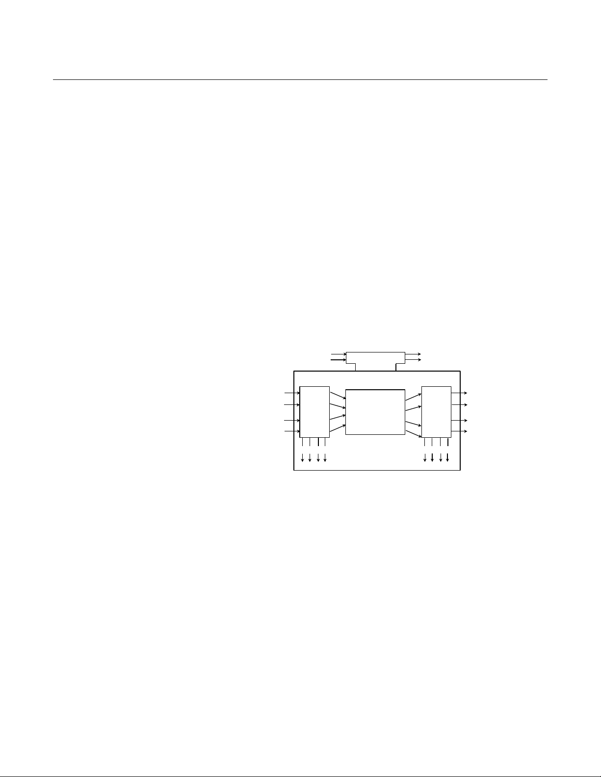
Rosemount 848T
Input Events Output Events
Input
Parameter
Linkages
Output
Parameter
Linkages
Processing
Algorithm
Execution
Control
Input
Snap
Status
Output
Snap
Status
Reference Manual
00809-0100-4697, Rev EA
October 2011
The Fieldbus FOUNDATION has established the function blocks by defining a
small set of parameters used in all function blocks called universal
parameters. The F
block classes, such as input, output, control, and calculation blocks. Each of
these classes has a small set of parameters established for it. They have also
published definitions for transducer blocks commonly used with standard
function blocks. Examples include temperature, pressure, level, and flow
transducer blocks.
The F
OUNDATION specifications and definitions allow vendors to add their own
parameters by importing and subclassing specified classes. This approach
permits extending function block definitions as new requirements are
discovered and as technology advances.
Figure C-1 illustrates the internal structure of a function block. When
execution begins, input parameter va lues from other blocks are snappe d-in by
the block. The input snap process ensures that these values do not change
during the block execution. New values received for these parameters do not
affect the snapped values and will not be used by the function block during
the current execution.
OUNDATION has also defined a standard set of function
Figure C-1. Function
Block Internal Structure
Once the inputs are snapped, the algorithm operates on them, generating
outputs as it progresses. Algorithm executions are controlled through the
setting of contained parameters. Contained parameters are internal to
function blocks and do not appear as normal input and output parameters.
However, they may be accessed and modified remotely, as specified by the
function block.
Input events may affect the operation of the algorith m. An execution control
function regulates the receipt of input events and the generation of output
events during execution of the algorithm. Upon completion of the algorithm,
the data internal to the block is saved for use in the next execution, and the
output data is snapped, releasing it for use by other function blocks.
C-2
A block is a tagged logical processing unit. The tag is the name of the block.
System management services locate a block by its tag. Thus the service
personnel need only know the tag of the block to access or change the
appropriate block parameters.
Function blocks are also capable of performing sho rt-term dat a collection an d
storage for reviewing their behavior.
Page 85

Reference Manual
00809-0100-4697, Rev EA
October 2011
Rosemount 848T
DEVICE DESCRIPTIONS Device Descriptio ns (D D) ar e specified tool definitions that are associated
with the Resource and Transducer Blocks. Device descriptions provide the
definition and description of the function blocks and their parameters.
To promote consistency of definition and understanding, descriptive
information, such as data type and length, is maintained in the device
description. Device Descriptions are written using an open language called
the Device Description Language (DDL). Param e te r tra ns fe rs between
function blocks can be easily verified because all parameters are described
using the same language. Once written, the device description can be stored
on an external medium, such as a CD-ROM or diskette. Users can then read
the device description from the external me diu m . Th e us e of an op en
language in the device description permits interoperability of function blocks
within devices from various vendors. Additionally, human interface devices,
such as operator consoles and computers, do not have to be programmed
specifically for each type of device on the bus. Instead their displays and
interactions with devices are driven from the device descriptions.
Device descriptions may also include a set of processing routines called
methods. Methods provide a procedure for accessing and manipulating
parameters within a device.
BLOCK OPERATION In addition to function blocks, fieldbus devices contain two other block types
to support the function blocks. These are the resource block and the
transducer block.
Instrument- Specific
Function Blocks
Resource Blocks
Resource blocks contain the hardware–specific characteristics associated
with a device; they have no input or output parameter s. The algorithm within a
resource block monitors and controls the general operation of the physical
device hardware. The execution of this algorithm is dependent on the
characteristics of the physical device, as defi ne d by the m anuf acturer. As a
result, the algorithm may cause the generation of events. There is only one
resource block defined for a device. For example, when the mode of a
resource block is “Out of Service (OOS),” it impacts all of the other blocks.
Transducer Blocks
Transducer blocks connect function blocks to local input/output functions.
They read sensor hardware and write to effector (actuator) hardware. This
permits the transducer block to execute as frequently as necessary to obtain
good data from sensors and ensure proper writes to the actuator without
burdening the function blocks that use the data. The transducer block also
isolates the function block from the vendor–specific characteristics of the
physical I/O.
Alerts When an alert occurs, execution control sends an event notification and waits
a specified period of time for an acknowledgment to be received. This occurs
even if the condition that caused the alert no longer exists. If the
acknowledgment is not received within the pre-specified time-out period, the
event notification is retransmitted, assuring that alert messages are not lost.
C-3
Page 86

Rosemount 848T
LAS
Basic Devices and/or link master devices
Link Master
Fieldbus Link
Reference Manual
00809-0100-4697, Rev EA
October 2011
Two types of alerts are defined for the block: events and alarms. Events are
used to report a status change when a block leaves a p articular state, su ch as
when a parameter crosses a threshold. Alarms not only report a status
change when a block leaves a particular state, but also report when it returns
back to that state.
NETWORK COMMUNICATION
Figure C-2. Simple, Single-Link
Fieldbus Network
Link Active Scheduler
(LAS)
Figure C-2 illustrates a simple fieldbus network consisting
of a single segment (link).
All links have one Link Active Scheduler (LAS). The LAS operates as the bus
arbiter for the link. The LAS does the following:
• recognizes and adds new devices to the link.
• removes non-responsive devices from the link.
• distributes Data Link Time (DL) and Link Scheduling Time (LS) on the
link. DL is a network-wide time periodically distributed by the LAS to
synchronize all device clocks on the bus. LS time is a link-specific time
represented as an offset from DL. It is used to indicate when the LAS
on each link begins and repeats its schedule. It is used by system
management to synchronize function block execution with the data
transfers scheduled by the LAS.
• polls devices for process loop data at scheduled transmission times.
• distributes a priority-driven token to devices between
scheduled transmissions.
C-4
Any device on the link may become the LAS. The devices that are capable of
becoming the LAS are called Link Master devices (LM). All other devices are
referred to as basic devices. When a segment first starts up, or upon failure of
the existing LAS, the link master devices on the segment bid to become the
LAS. The link master that wins the bid begins operating as the LAS
immediately upon completion of the bidding process. Link masters that do not
become the LAS act as basic devices. However, the link masters can act as
LAS backups by monitoring the link for failure of the LAS and then bidding to
become the LAS when a LAS failure is detected.
Only one device can communicate at a time. Permission to communicate on
the bus is controlled by a centralized token passed between devices by the
LAS. Only the device with the token can communicate. The LAS maintains a
list of all devices that need access to the bus. This list is called the “Live List.”
Two types of tokens are used by the LAS. A time-critical token, Compel Data
(CD), is sent by the LAS according to a schedule. A non-time critical token,
pass token (PT), is sent by the LAS to each device in ascending numerical
order according to address.
Page 87

Reference Manual
FB 1
C
D
Data
FB 2
MID
MID x ST
MID
00809-0100-4697, Rev EA
October 2011
Rosemount 848T
There may be many LM devices on a segment but only the LAS is actively
controlling communication traffic. The remaining LM devices on the segment
are in a stand-by state, ready to take over if the primary LAS fails. This is
achieved by constantly monitoring the communication traffic on the bus and
determining if activity is not present. Since there can be multiple LM devices
on the segment when the primary LAS fails, the device with the lowest node
address will become the primary LAS and take control of the bus. Using this
strategy, multiple LAS failures can be handled with no loss of the LAS
capability of the communications bus.
LAS Parameters
There are many bus communication parameters but on ly a few are used. For
standard RS-232 communications, the configuration p arameters are baud
rate, start / stop bits, and parity. The key parameters for H1 F
fieldbus are as follows.
• Slot Time (ST) – Used during the bus master el ection process. It is the
maximum amount of time permitted for device A to send a message to
device B. Slot time is a parameter which defines a worst case delay
which includes internal delay in the sending device and the receiving
device. Increasing the value of ST slows down bus traffic because a
LAS device must wait longer prior to determining that the LM is down.
• Minimum Inter-PDU Delay (MID) – The minimum gap between two
messages on the fieldbus segment or it is the amount of time between
the last byte of one message and the first byte of the next message.
The units of the MID are octets. An octet is 256 s, hence the units for
MID are approximately
1
/4 ms. This would mean an MID of 16 would
specify approximately a minimum of 4 ms between messages on the
Fieldbus. Increasing the value of MID slows down bus traf fic because a
larger “gap” between messages occurs.
• Maximum Response (MRD) – Defines the maximum amount of time
permitted to respond to an immediate response request, e.g. CD, PT.
When a published value is requested using the CD command, the MRD
defines how long before the device publishes the data. Increasing this
parameter will slow down the bus traffic by decreasing how fast CDs
can be put onto the network. The MRD is measured in units of ST.
• Time Synchronization Class (TSC) – A variable that de fines how long
the device can estimate its time before drifting out of specific limits. The
LM will periodically send out time update messages to synchronize
devices on the segment. Decreasing the parameter number increases
the number of times that time distribution messages must be published,
increasing bus traffic and overhead for the LM device. See Figure C-3.
OUNDATION
Figure C-3. LAS Parameter
diagram
C-5
Page 88

Reference Manual
00809-0100-4697, Rev EA
Rosemount 848T
Backup LAS
A LM device is one that has the ability to control the communications on the
bus. The LAS is the LM capable device that is currently in control of the bus.
While there can be many LM devices acting as backups, there can only be
one LAS. The LAS is typically a host system but for stand-alone applicatio ns,
a device may be providing the role of primary LAS.
October 2011
Addressing To setup, configure, and communicate with other devices on a segment, a
device must be assigned a permanent address. Unless requested otherwise,
it is assigned a temporary address when shipped from the factory.
F
OUNDATION fieldbus uses addresses between 0 and 255. Addresses 0
through 15 are reserved for group addressing and for use by the data link
layer.
If there are two or more devices on a segment with the same address, the first
device to start up will use the assigned address. Each of the other devices will
be given one of the four temporary addresses. If a temporary address is not
available, the device will be unavailable until a temporary address is available.
Use the host system documentation to commission a device and assign a
permanent address.
Scheduled Transfers Information is transferred between devices over the FOUNDATION fieldbus
using three different types of reporting.
Publisher/Subscriber
This type of reporting is used to transfer critical process loop data, such as the
process variable. The data producers (publishers) post the dat a in a buffer
that is transmitted to the subscriber, when the publisher receives the Compel
Data (CD). The buffer contains only one copy of the data. New data
completely overwrites previous data. Updates to published data are
transferred simultaneously to all subscribers in a single broadcast. Transfers
of this type can be scheduled on a precisely periodic basis.
Report Distribution
This type of reporting is used to broadcast and multicast event and trend
reports. The destination address may be predefined so that all reports are
sent to the same address, or it may be provided separately with each report.
Transfers of this type are queued. They are delivered to the receivers in the
order transmitted, although there may be gaps due to corrupted transfers.
These transfers are unscheduled and occur between scheduled transfer s at a
given priority.
Client/Server
This type of reporting is used for request/response exchanges between pairs
of devices. Like Report Distribution reporting, the transfers are queued,
unscheduled, and prioritized. Queued means the messages are sent and
received in the order submitted for transmission, according to their priority,
without overwriting previous messages. However, unlike Report Distribution,
these transfers are flow controlled and employ a retransmission procedure to
recover from corrupted transfers.
C-6
Page 89
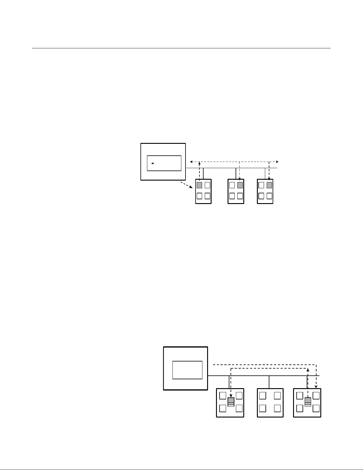
Reference Manual
Schedule
X, Y, Z
CD(X,A)
DT(A)
Device X
Device Y Device Z
ACDAB
PS PS PAS
LAS
Schedule
X, Y, Z
PT(Z)
Device X Device Y Device Z
ACDAB
PS PS PAS
LAS
DT(M)
MM
00809-0100-4697, Rev EA
October 2011
Figure C-4. Scheduled Data
Transfer
Rosemount 848T
Figure C-4 diagrams the method of scheduled data transfer. Scheduled data
transfers are typically used for the regular cyclic transfer of process loop data
between devices on the fieldbus. Scheduled transfers use publisher/
subscriber type of reporting for data transfer. The LAS maintains a list of
transmit times for all publishers in all devices that need to be cyclically
transmitted. When it is time for a device to publish data, the LAS issues a CD
message to the device. Upon receipt of the CD, the device broadcasts or
“publishes” the data to all devices on the fieldbus. Any device that is
configured to receive the data is called a “subscriber.”
LAS = Link Active Scheduler
P = Publisher
S = Subscriber
CD = Compel Data
DT = Data Transfer Packet
Unscheduled Transfers Figure C-5 diagrams an unscheduled transfer. Unscheduled transfers are
used for things like user-initiated changes, including set point changes, mode
changes, tuning changes, and upload /d ow nlo ad . Un sch ed u led tra ns fer s use
either report distribution or client/server type of reporting for transferring data.
All of the devices on the F
unscheduled messages between transmissions of scheduled data. The LAS
grants permission to a device to use t he fieldbu s by issuing a p ass to ken (PT)
message to the device. When the device receives the PT, it is allowed to send
messages until it has finished or until the “maximum token hold time” has
expired, whichever is the shorter time. The message may be sent to a single
destination or to multiple destinations.
Figure C-5. Unscheduled Data
Transfer
OUNDATION fieldbus are given a chance to send
P = Publisher S = Subscriber PT = Pass Token M = Message
C-7
Page 90

Rosemount 848T
Macrocycle Start Time
Offset from macrocycle
start time = 0 for AI
Execution
Device 1
Scheduled
Communication
Sequence
Repeats
Macrocycle
Offset from macrocycle start
time = 20 for AI Communication
Unscheduled
Communication
Device 2
Offset from macrocycle start
time = 30 for PID Execution
Offset from macrocycle start
time = 50 for AO Execution
AI
AI
PID
AO
PID
AO
Reference Manual
00809-0100-4697, Rev EA
October 2011
Function Block
Scheduling
Figure C-6. Example Link
Schedule Showing Scheduled
and Unscheduled
Communication
Figure C-6 shows an example of a link schedule. A single iteration of the
link-wide schedule is called the macrocycle. When the system is configured
and the function blocks are linked, a master link-wide schedule is created for
the LAS. Each device maintains its portion of the link-wide schedule, known
as the Function Block Schedule. The Function Block Schedule indicates when
the function blocks for the device are to be executed. The scheduled
execution time for each function block is represented as an offset from the
beginning of the macrocycle start time.
C-8
To support synchronization of schedules, periodically Link Scheduling (LS)
time is distributed. The beginning of the macrocycle represents a common
starting time for all Function Block schedules on a link and for the LAS
link-wide schedule. This permits function block executions and their
corresponding data transfers to be synchronized in time.
Page 91

Reference Manual
OUT_D
AI
OUT
00809-0100-4697, Rev EA
October 2011
Appendix D Function Blocks
Analog Input (AI) Function Block . . . . . . . . . . . . . . . . . . . page D-1
Multiple Analog Input (MAI) Function Block . . . . . . . . . .page D-9
Input Selector Function Block . . . . . . . . . . . . . . . . . . . . . . page D-15
Rosemount 848T
ANALOG INPUT (AI) FUNCTION BLOCK
The Analog Input (AI) function block processes field device measurements
and makes them available to other function blocks. The output value from the
AI block is in engineering units and contains a status indicating the quality of
the measurement. The measuring device may have several measurements or
derived values available in different channels. Use the chann el number to
define the variable that the AI block processes.
The AI block supports alarming, signal scaling, signal filtering, signal status
calculation, mode control, and simulation. In Automatic mode, the block’s
output parameter (OUT) reflects the process variable (PV) value and status.
In Manual mode, OUT may be set manually. The Manual mode is reflected on
Out = The block output value and status
Out_D = Discrete output that signals a
selected alarm condition
the output status. A discrete output (OUT_D) is prov ided to indicate whether a
selected alarm condition is active. Alarm detection is based on the OUT value
and user specified alarm limits. The block execution time is 30 ms.
Table D-1. Analog Input Function Block Parameters
Number Parameter Units Description
01 ST_REV None The revision level of the static data associated with the function block. The
02 TAG_DESC None The user description of the intended application of the block.
03 STRATEGY None The strategy field can be used to identify a grouping of blocks. This data is not
04 ALERT_KEY None The identification number of the plant unit. This information may be used in the host
05 MODE_BLK None The actual, target, permitted, and normal modes of the block.
06 BLOCK_ERR None This parameter reflects the error status associated with the hardware or software
07 PV EU of XD_SCALE The process variable used in block execution.
08 OUT EU of OUT_SCALE
or XD_SCALE if in
direct L_TYPE
09 SIMULATE None A group of data that contains the current transducer value and status, the simulated
revision value will be incremented each time a static parameter value in the block is
changed.
checked or processed by the block.
for sorting alarms, etc.
Actual: The mode the “block is currently in”
Target: The mode to “go to”
Permitted: Allowed modes that target may take on
Normal: Most common mode for target
components associated with a block. It is a bit string, so that multiple errors may be
shown.
The block output value and status.
transducer value and status, and the enable/disable bit.
www.rosemount.com
Page 92

Reference Manual
00809-0100-4697, Rev EA
Rosemount 848T
Table D-1. Analog Input Function Block Parameters
Number Parameter Units Description
10 XD_SCALE None The high and low scale values, engineering units code, and number of digits to
the right of the decimal point associated with the channel input value. The
XD_SCALE units code must match the units code of the measurement channel in
the transducer block. If the units do not match, the block will not transition to MAN
or AUTO.
11 OUT_SCALE None The high and low scale values, engineering units code, and number of digits to the
right of the decimal point associated with OUT when L_TYPE is not direct.
12 GRANT_DENY None Options for controlling access of host computers and local control panels to
operating, tuning, and alarm parameters of the block. Not used by device.
13 IO_OPTS None Allows the selection of input/output options used to alter the PV. Low cutoff enabled
is the only selectable option.
14 STATUS_OPTS None Allows the user to select options for status handling and processing. The options
supported in the AI block are the following:
Propagate fault forward
Uncertain if limited
Bad if limited
Uncertain if Manual mode.
15 CHANNEL None The CHANNEL value is used to select the measurement value. Configure the
CHANNEL parameter before configuring the XD_SCALE parameter. Refer to Table
3-5 on page 3-11.
16 L_TYPE None Linearization type. Determines whether the field value is used directly (Direct), is
converted linearly (Indirect), or is converted with the square root (Indirect Square
Root).
17 LOW_CUT % If percentage value of transducer input fails below this, PV = 0.
18 PV_FTIME Seconds The time constant of the first-order PV filter. It is the time required for a 63% change
in the PV or OUT value.
19 FIELD_VAL Percent The value and status from the transducer block or from the simulated input when
simulation is enabled.
20 UPDATE_EVT None This alert is generated by any change to the static data.
21 BLOCK_ALM None The block alarm is used for all configuration, hardware, connection failure or system
problems in the block. The cause of the alert is entered in the subcode field. The first
alert to become active will set the Active status in the Status parameter. As soon as
the Unreported status is cleared by the alert reporting task, another block alert may
be reported without clearing the Active status, if the subcode has changed.
22 ALARM_SUM None The summary alarm is used for all process alarms in the block. The cause of the
alert is entered in the subcode field. The first alert to become active will set the
Active status in the Status parameter. As soon as the Unreported status is cleared
by the alert reporting task, another block alert may be reported without clearing the
Active status, if the subcode has changed.
23 ACK_OPTION None Used to set auto acknowledgment of alarms.
24 ALARM_HYS Percent The amount the alarm value must return within the alarm limit before the associated
active alarm condition clears.
25 HI_HI_PRI None The priority of the HI HI alarm.
26 HI_HI_LIM EU of PV_SCALE The setting for the alarm limit used to detect the HI HI alarm condition.
27 HI_PRI None The priority of the HI alarm.
28 HI_LIM EU of PV_SCALE The setting for the alarm limit used to detect the HI alarm condition.
29 LO_PRI None The priority of the LO alarm.
30 LO_LIM EU of PV_SCALE The setting for the alarm limit used to detect the LO alarm condition.
31 LO_LO_PRI None The priority of the LO LO alarm.
32 LO_LO_LIM EU of PV_SCALE The setting for the alarm limit used to detect the LO LO alarm condition.
33 HI_HI_ALM None The HI HI alarm data, which includes a value of the alarm, a timestamp of
occurrence and the state of the alarm.
34 HI_ALM None The HI alarm data, which includes a value of the alarm, a timestamp of occurrence
and the state of the alarm.
35 LO_ALM None The LO alarm data, which includes a value of the alarm, a timestamp of occurrence
and the state of the alarm.
October 2011
D-2
Page 93

Reference Manual
PV_FTIME
63% of Change
OUT (mode in man)
OUT (mode in auto)
PV
Time (seconds)
FIELD_VAL
00809-0100-4697, Rev EA
October 2011
Rosemount 848T
Table D-1. Analog Input Function Block Parameters
Number Parameter Units Description
36 LO_LO_ALM None The LO LO alarm data, which includes a value of the alarm, a timestamp of
occurrence and the state of the alarm.
37 OUT_D None Discrete output to indicate a selected alarm condition.
38 ALM_SEL None Used to select the process alarm conditions that will cause the OUT_D parameter to
be set.
39 STDDEV % of OUT Range Standard deviation of the measurement for 100 macrocycles.
40 CAP_STDDEV % of OUT Range Capability standard deviation, the best deviation that can be achieved.
Functionality Simulation
To support testing, either change the mode of the block to manual and adjust
the output value, or enable simulation through the configuration tool and
manually enter a value for the measurement value and its status. In
simulation, the ENABLE jumper must be set on the field device.
NOTE
All F
OUNDATION fieldbus instruments have a simulation jumper. As a safety
measure, the jumper has to be reset every time there is a power interruption.
This measure is to prevent devices that went through simulation in the staging
process from being installed with simulation enabled.
Figure D-1. Analog Input
Function Block Timing Diagram
With simulation enabled, the actual measurement value has no impact on the
OUT value or the status.
D-3
Page 94

Rosemount 848T
Analog
Measurement
Access
Analog
Meas.
CHANNEL
SIMULATE
OUT_SCALE
XD_SCALE
FIELD_VAL
L_TYPE
IO_OPTS
PV_FTIME
MODE
STATUS_OPTS
HI_HI_LIM
HI_LIM
LO_LO_LIM
LO_LIM
ALARM_HYS
ALM_SEL
OUT_D
OUT
PV
Convert
Cutoff Filter
Status
Calc.
Alarm
Detection
LOW_CUT
FIELD_VAL
100 Channel Value EU*@0%–
EU*@100% EU*@0%–
------------------------------------------------------------------------------------------- -=
* XD_SCALE values
PV Channel Value=
PV
FIELD_VAL
100
-------------------------------
EU**@100% EU**@0%–EU**@0%+=
** OUT_SCALE values
Figure D-2. Analog Input
Function Block Schematic
Reference Manual
00809-0100-4697, Rev EA
October 2011
OUT = Block output value and status
OUT_D = Discrete output that signals a selected alarm condition
Filtering
The filtering feature changes the response time of the device to smooth
variations in output readings caused by rapid changes in input. Adjust the
filter time constant (in seconds) using the PV_FTIME parameter. Set the filter
time constant to zero to disable the filter feature.
Signal Conversion
Set the signal conversion type with the Linearization Type (L_TYPE)
parameter. View the converted signal (in percent of XD_SCALE) through the
FIELD_VAL parameter.
Choose from direct, indirect, or indirect square root signal conversion with the
L_TYPE parameter.
Direct
Direct signal conversion allows the signal to pass through the accessed
channel input value (or the simulated value when simulation is enabled).
Indirect
D-4
Indirect signal conversion converts the signal linearly to the accessed channel
input value (or the simulated value when simulation is enabled) from its
specified range (XD_SCALE) to the range an d un its of the PV and OUT
parameters (OUT_SCALE).
Page 95

Reference Manual
PV
FIELD_VAL
100
-------------------------------
EU**@100% EU**@0%–EU**@0%+=
** OUT_SCALE values
00809-0100-4697, Rev EA
October 2011
Rosemount 848T
Indirect Square Root
Indirect Square Root signal conversion takes the square root of the value
computed with the indirect signal conversion and scales it to the range and
units of the PV and OUT parameters.
When the converted input value is below the limit specified by the LOW_CUT
parameter, and the Low Cutoff I/O option (IO_OPTS) is enabled (True), a
value of zero is used for the converted value (PV). This optio n eliminates false
readings when the differential pressure measurement is close to zero and it
may be useful with zero-based measurement devices such as flowmeters.
NOTE
Low Cutoff is the only I/O option supported by the AI block. Set the I/ O option
when the block is OOS.
Block Errors
Table D-2. BLOCK_ERR
Conditions
Table D-2 lists conditions reported in the BLOCK_ERR parameter. Conditions
in bold are inactive for the AI block and are given here for reference.
Number Name and Description
0 Other
1 Block Configuration Error: the selected channel carr ies a measurement that is
incompatible with the engineering units selected in XD_SCALE, the L_TYPE
parameter is not configured, or CHANNEL = zero.
2 Link Configuration Error
3 Simulate Active: Simulation is enabled and the block is using a simulated value in
its execution.
4 Local Override
5 Device Fault State Set
6 Device Needs Maintenance Soon
7 Input Failure/Process Variable has Bad Status: The hardware is bad, or a bad
status is being simulated.
8 Output Failure: The output is bad based primarily upon a bad input.
9 Memory Failure
10 Lost Static Data
11 Lost NV Data
12 Readback Check Failed
13 Device Needs Maintenance Now
14 Power Up
15 Out of Service: The actual mode is out of service.
D-5
Page 96

Rosemount 848T
Reference Manual
00809-0100-4697, Rev EA
October 2011
Modes
The AI Function Block supports three modes of operation as defined by the
MODE_BLK parameter:
Manual (Man)
The value of the block output (OUT) may be set manually
Automatic (Auto)
OUT reflects the analog input measurement or the simulated value when
simulation is enabled.
Out of Service (OOS)
The block is not processed. FIELD_VAL and PV are not updated and the
OUT status is set to Bad: Out of Service. The BLOCK_ERR parameter
shows Out of Service. In this mode, changes can be made to all
configurable parameters.
Alarm Detection
A block alarm will be generated whenever the BLOCK_ERR has an error bit
set. The types of block error for the AI block are defined above.
Table D-3. Alarm Priority Levels
Process Alarm detection is based on the OUT value. Configure the alarm
limits of the following standard alarms:
• High (HI_LIM)
• High high (HI_HI_LIM)
• Low (LO_LIM)
• Low low (LO_LO_LIM)
To avoid alarm chatter when the variable is oscillating around the alarm limit,
an alarm hysteresis in percent of the PV span can be set using the
ALARM_HYS parameter. The priority of each alarm is set in the following
parameters:
•HI_PRI
•HI_HI_PRI
•LO_PRI
•LO_LO_PRI
Number Description
0 The priority of an alarm condition changes to 0 after the condition that caused the
alarm is corrected.
1 An alarm condition with a priority of 1 is recognized by the system, but is not
reported to the operator.
2 An alarm condition with a priority of 2 is reported to the operator, but does not
require operator attention (such as diagnostics and system alerts).
3-7 Alarm conditions of priority 3 to 7 are advisory alarms of increasing priority.
8-15 Alarm conditions of priority 8 to 15 are critical alarms of increasing priority.
D-6
Page 97

Reference Manual
00809-0100-4697, Rev EA
October 2011
Rosemount 848T
Status Handling
Normally, the status of the PV reflects the status of the measurement value,
the operating condition of the I/O card, and any active alarm condition. In Auto
mode, OUT reflects the value and status quality of the PV. In Man mode, the
OUT status constant limit is set to indicate that th e value is a const ant and the
OUT status is Good.
If the sensor limit exceeds the high or low range, PV status is set high or low
and EU range status is set to uncertain.
In the STATUS_OPTS parameter, select from the following options to control
the status handling:
BAD if Limited
Sets the OUT status quality to Bad when the value is higher or lower than
the sensor limits.
Uncertain if Limited
Sets the OUT status quality to Uncertain when the value is hig her or lower
than the sensor limits.
Uncertain if in Manual mode
The status of the Output is set to Uncertain when the mode is set to
Manual
NOTES
1. The instrument must be in OOS mode to set the status option.
2. The AI block only supports the BAD if Limited option, uncertain if limited,
and uncertain if manual.
Advanced Features
The AI function block provided with Rosemount fieldbus devices provides
added capability through the addition of the following parameters:
ALARM_TYPE
Allows one or more of the process alarm conditions detected by the AI
function block to be used in setting its OUT_D parameter.
OUT_D
Discrete output of the AI function block based on the detection of process
alarm condition(s). This parameter may be linked to other function blocks
that require a discrete input based on the detected alarm condition.
STD_DEV and CAP_STDDEV
Diagnostic parameters that can be used to determine the variability of the
process.
D-7
Page 98

Rosemount 848T
Reference Manual
00809-0100-4697, Rev EA
October 2011
Application Information
The configuration of the AI function block and its associated output channels
depends on the specific application. A typical configuration for the AI block
involves the following parameters:
CHANNEL
The device supports more than one measurement, so verify that the
selected channel contains the appropriate measureme nt or derived value.
Refer to Table 3-5 on page 3-11 for a listing of available channels on the
848T.
L_TYPE
Select Direct when the measurement is in the desired engineering units
for the block output. Select Indirect when converting the measured
variable into another, for example, pressure into level or flow into energy.
SCALING
XD_SCALE provides the range and units of the measurement and
OUT_SCALE provides the range and engineering units of the output.
OUT_SCALE is only used when in indirect or indirect square root.
AI Block
Troubleshooting
Symptom Possible Causes Corrective Action
Mode will not leave OOS Target mode not set. Set target mode to something other than OOS.
Process and/or block
alarms will not work.
Value of output does not
make sense
Cannot set HI_LIMIT,
HI_HI_LIMIT, LO_LIMIT,
or LO_LO_LIMIT Values
Configuration error BLOCK_ERR will show the configuration error bit set. The following are parameters that
Resource block The actual mode of the Resource block is OOS. See Resource Block Diagnostics for
Schedule Block is not scheduled and therefore cannot execute to go to Target Mode. Typically,
Features FEATURES_SEL does not have Alerts enabled. Enable the Alerts bit.
Notification LIM_NOTIFY is not high enough. Set equal to MAX_NOTIF Y. Alarm not linked to host.
Status Options ST ATUS_OPTS has Propagate Fault Forward bit set. This should be cleared to cause an
Linearization Type L_TYPE must be set to Direct, Indirect, or Indirect Square Root and cannot be left at
Scaling Scaling parameters are set incorrectly:
Scaling L imit values are outside the OUT_SCALE.EU0 and OUT_SCALE.EU100 values.
must be set before the block is allowed out of OOS:
• CHANNEL must be set to a valid value and cannot be left at initial value of 0.
• XD_SCALE
channel value. Setting the units in the AI block automatically sets them in the
XD_BLOCK.
• L_TYPE must be set to Direct, Indirect, or Indirect Square Root and cannot be left at
initial value of 0.
corrective action.
BLOCK_ERR will show “Power-Up” for all blocks that are not scheduled. Schedule the
block to execute.
alarm to occur.
initial value of 0.
• XD_SCALE.EU0 and EU100 should match that of the transducer block
channel value.
• OUT_SCALE
• Both STB on each asic used must by in auto.
Change OUT_SCALE or set values within range.
.UNITS_INDEX must match the units in the transducer block
.EU0 and EU100 are not set properly.
D-8
Page 99

Reference Manual
OUT_1
MAI
OUT_2
OUT_3
OUT_4
OUT_5
OUT_6
OUT_7
OUT_8
00809-0100-4697, Rev EA
October 2011
Rosemount 848T
MULTIPLE ANALOG INPUT (MAI) FUNCTION BLOCK
The Multiple Analog Input (MAI) function block has the ability to process up to
eight field device measurements and make them available to other function
blocks. The output values from the MAI block are in engineering units and
contain a status indicating the quality of the measurement. The measuring
device may have several measurements or derived values available in
different channels. Use the channel numbers to define the variables that the
MAI block processes.
The MAI block supports signal scaling, signal filtering, signal status
calculation, mode control, and simulation. In Automatic mode, the block’s
output parameters (OUT_1 to OUT_8) reflects the process variable (PV)
values and status. In Manual mode, OUT may be set manually. The Manual
mode is reflected on the output status. Table D-4 lists the MAI block
parameters and their unit s of measur e, d escription s, and indexnumbers. The
block execution time is 30 ms.
Out1 = The block output value and status
for the first channel.
Table D-4. Multiple Analog Input Function Block Parameters
Number Parameter Units Description
1 ST_REV None The revision level of the static data associated with the input selector block. The
2 TAG_DESC None The user description of the intended application of the block.
3 STRATEGY None The strategy field can be used to identify grouping of blocks. This data is not
4 ALERT_KEY None The identification number of the plant unit. This information may be used in the host
5 MODE_BLK None The actual, target, permitted, and normal modes of the block.
6 BLOCK_ERR None This parameter reflects the error status associated with the hardware or software
7 CHANNEL None Allows for custom channel setting. Valid values include:
8, 9, 10, 11,
12, 13, 14,
15
16 UPDATE_EVT None This alert is generated by any change to the static data
17 BLOCK_ALM None The block alarm is used for all configuration, hardware connection feature, or
18 SIMULATE None A group of data that contains the current sensor transducer value and status, and
OUT (1, 2, 3, 4, 5,
6, 7, 8)
EU of OUT_SCALE The block output value and status
revision value will be incremented each time a static parameter value in the block is
changed.
checked or processed by the block.
for sorting alarms, etc.
Actual: The mode the “block is currently in”
Target: The mode to “go to”
Permitted: Allowed modes that target may take on
Normal: Most common mode for target
components associated with a block. It is a bit string, so that multiple errors may be
shown.
0: Unitialized
1: Channels 1 to 8 (index values 27 to 34 can only be set to their corresponding
channel number, i.e. CHANNEL_X=X)
2: Custom settings (index values 27 to 34 can be configured for any valid channel
as defined by the DD)
system problems in the block. The cause of the alert is entered in the subcode field.
The first alert to become active will set the Active status in the Status parameter. As
soon as the Unreported status is cleared by the alert reporting task, another block
may be reported without clearing the Active status, if the subcode has changed.
the enable/disable bit.
D-9
Page 100

Reference Manual
00809-0100-4697, Rev EA
Rosemount 848T
Table D-4. Multiple Analog Input Function Block Parameters
Number Parameter Units Description
19 XD_SCALE None The high and low scale values, engineering units code and number of digits to the
right of the decimal point associated with the channel input value. The XD_SCALE
units code must match the units code of the measurement channel in the
transducer block. If the units do not match, the block will not transition to MAN or
AUTO. It will automatically change units in the STB block to the last one written.
Multiple blocks reading the same channel may conflict (only one unit type per
channel).
20 OUT_SCALE None The high and low scale values, engineering unit code and number of digits to the
21 GRANT_DENY None Options for controlling access of host computers and local control panels for
22 IO_OPTS None Allows the selection of input/output options used to alter the PV . Low cutof f enabled
23 STATUS_OPTS None Allows the user to select options for status handling and processing. The options
24 L_TYPE None Linearization type. Determines whether the field value is uses directly (Direct), is
25 LOW_CUT % If percentage value of the sensor transducer input falls below this, PV = 0
26 PV_FTIME Seconds The time constant of the first-order PV filter. It is the time required for a 63% change
27, 28, 29,
30, 31, 32,
33, 34
35, 36, 37,
38, 39, 40,
41, 42
43, 44, 45,
46, 47, 48,
49, 50
CHANNEL_(1, 2,
3,4 5, 6, 7, 8)
STDDEV_(1, 2, 3,
4, 5, 6, 7, 8)
CAP_STDDEV_(1
, 2, 3, 4, 5, 6, 7, 8)
None The CHANNEL (1, 2, 3, 4, 5, 6, 7, 8) value is used to select the measurement
% of OUT Range Standard deviation of the corresponding measurement.
% of OUT Range Capability standard deviation, the best deviation that can be achieved.
right of the decimal point associated with OUT.
operating, tuning, and alarm parameters of the block. Not used by device.
is the only selectable option.
supported in the MAI block are the following:
• Propagate fault forward
• Uncertain if limited
• Bad if limited
• Uncertain if manual mode
converted linearly (Indirect), or is converted with the square root (Indirect Square
Root)
in the IN value.
value. See T able D-4 on page D-6 for available channels. Configure the CHANNEL
parameters to custom (2) before configuring the CHANNEL parameters.
October 2011
Functionality Simulation
To support testing, either change the mode of the block to manual and adjust
the output value or enable simulation through the configuration tool and
manually enter a value for the measurement value and its status (this single
value will apply to all outputs). In both cases, first set the ENABLE jumper on
the field device.
NOTE
All F
OUNDATION fieldbus instruments have a simulation jumper. As a safety
measure, the jumper has to be reset every time there is a power interruption.
This measure is to prevent devices that went through simulation in the staging
process from being installed with simulation enabled.
With simulation enabled, the actual measurement value has no impact on the
OUT value or the status. The OUT values will all have the same value as
determined by the simulate value.
D-10
 Loading...