

Page 1
00809-0200-4705, Rev AA
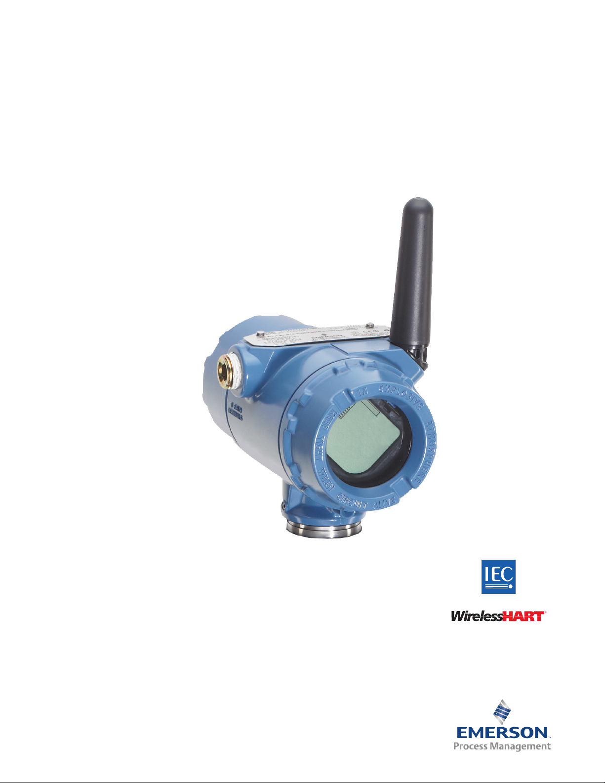
Rosemount 705 Wireless Totalizing
Transmitter
Reference Manual
May 2015
Page 2

Page 3
Reference Manual
NOTICE
00809-0200-4705, Rev AA
Rosemount 705 Wireless
Totalizing Transmitter
Title Page
May 2015
Read this manual before working with the product. For personal and system safety, and for
optimum product performance, make sure to thoroughly understand the contents before
installing, using, or maintaining this product.
The United States has two toll-free assistance numbers and one international number.
Customer Central
1 800 999 9307 (7:00 a.m. to 7:00 p.m. CST)
National Response Center
1 800 654 7768 (24 hours a day)
Equipment service needs
International
1 952 906 8888
The products described in this document are NOT designed for nuclear-qualified
applications.
Using non-nuclear qualified products in applications that require nuclear-qualified
hardware or products may cause inaccurate readings.
For information on Rosemount nuclear-qualified products, contact an Emerson Process
Management Sales Representative.
Explosions could result in death or serious injury.
Installation of this transmitter in an explosive environment must be in accordance with the
appropriate local, national, and international standards, codes, and practices. Review the
approvals section of the 705 Reference Manual for any restrictions associated with a safe
installation.
Before connecting a Field Communicator in an explosive atmosphere, ensure the
instruments are installed in accordance with intrinsically safe or non-incendive field
wiring practices.
Electrical shock can result in death or serious injury.
Avoid contact with the leads and terminals. High voltage that may be present on leads
can cause electrical shock.
iii
Page 4

Title Page
NOTICE
NOTICE
NOTICE
May 2015
Reference Manual
00809-0200-4705, Rev AA
The 705 Transmitter and all other wireless devices should be installed only after the Smart
Wireless Gateway has been installed and is functioning properly. Wireless devices should
also be powered up in order of proximity from the Smart Wireless Gateway, beginning with
the closest. This will result in a simpler and faster network installation.
Shipping considerations for wireless products:
The unit was shipped to you without the power module installed. Remove the power
module prior to shipping.
Each power module contains two “C” size primary lithium batteries. Primary lithium
batteries are regulated in transportation by the U. S. Department of Transportation, and are
also covered by IATA (International Air Transport Association), ICAO (International Civil
Aviation Organization), and ARD (European Ground Transportation of Dangerous Goods). It
is the responsibility of the shipper to ensure compliance with these or any other local
requirements. Consult current regulations and requirements before shipping.
Power module considerations:
The power module with the wireless unit contains two “C” size primary lithium/thionyl
chloride batteries. Each battery contains approximately 2.5 grams of lithium, for a total of 5
grams in each pack. Under normal conditions, the battery materials are self-contained and
are not reactive as long as the batteries and the pack integrity are maintained. Care should
be taken to prevent thermal, electrical, or mechanical damage. Contacts should be
protected to prevent premature discharge.
Battery hazards remain when cells are discharged.
Power modules should be stored in a clean and dry area. For maximum battery life, storage
temperature should not exceed 30 °C.
The power module has surface resistivity greater than one gigaohm and must be properly
installed in the wireless device enclosure. Care must be taken during transportation to and
from the point of installation to prevent electrostatic charge build-up.
iv
Page 5

Reference Manual
00809-0200-4705, Rev AA
Contents
1Section 1: Introduction
Contents
May 2015
1.1 Safety messages. . . . . . . . . . . . . . . . . . . . . . . . . . . . . . . . . . . . . . . . . . . . . . . . . . . . . . . . 1
1.1.1 Warnings . . . . . . . . . . . . . . . . . . . . . . . . . . . . . . . . . . . . . . . . . . . . . . . . . . . . . . . .1
1.2 Transmitter overview . . . . . . . . . . . . . . . . . . . . . . . . . . . . . . . . . . . . . . . . . . . . . . . . . . . 1
1.2.1 Functions of the transmitter. . . . . . . . . . . . . . . . . . . . . . . . . . . . . . . . . . . . . . . . 2
1.2.2 Wireless considerations . . . . . . . . . . . . . . . . . . . . . . . . . . . . . . . . . . . . . . . . . . . . 2
1.2.3 Choosing an installation location and position . . . . . . . . . . . . . . . . . . . . . . . .3
1.2.4 Electrical . . . . . . . . . . . . . . . . . . . . . . . . . . . . . . . . . . . . . . . . . . . . . . . . . . . . . . . . .4
1.2.5 Verifying operating atmosphere . . . . . . . . . . . . . . . . . . . . . . . . . . . . . . . . . . . .4
1.3 Service support. . . . . . . . . . . . . . . . . . . . . . . . . . . . . . . . . . . . . . . . . . . . . . . . . . . . . . . . .5
1.4 Product recycling/disposal . . . . . . . . . . . . . . . . . . . . . . . . . . . . . . . . . . . . . . . . . . . . . . .5
2Section 2: Configuration
2.1 Safety messages. . . . . . . . . . . . . . . . . . . . . . . . . . . . . . . . . . . . . . . . . . . . . . . . . . . . . . . . 7
2.1.1 Warnings . . . . . . . . . . . . . . . . . . . . . . . . . . . . . . . . . . . . . . . . . . . . . . . . . . . . . . . .7
2.1.2 Connecting the turbine meter or pulse output device . . . . . . . . . . . . . . . . . 7
2.2 Configuring the transmitter on the bench . . . . . . . . . . . . . . . . . . . . . . . . . . . . . . . . . 8
2.3 Supported Engineering Unit Codes. . . . . . . . . . . . . . . . . . . . . . . . . . . . . . . . . . . . . . . .9
2.4 Joining the device to a network . . . . . . . . . . . . . . . . . . . . . . . . . . . . . . . . . . . . . . . . . .10
3Section 3: Mounting
3.1 Safety messages. . . . . . . . . . . . . . . . . . . . . . . . . . . . . . . . . . . . . . . . . . . . . . . . . . . . . . .11
3.1.1 Warnings . . . . . . . . . . . . . . . . . . . . . . . . . . . . . . . . . . . . . . . . . . . . . . . . . . . . . . .11
3.2 Installing the transmitter . . . . . . . . . . . . . . . . . . . . . . . . . . . . . . . . . . . . . . . . . . . . . . .12
3.2.1 Installing the transmitter in a direct mount configuration . . . . . . . . . . . . .12
3.2.2 Installing the transmitter in a remote mount configuration. . . . . . . . . . . .14
3.3 Remote antenna (optional) . . . . . . . . . . . . . . . . . . . . . . . . . . . . . . . . . . . . . . . . . . . . .15
3.3.1 WN remote antenna option . . . . . . . . . . . . . . . . . . . . . . . . . . . . . . . . . . . . . . .16
3.4 LCD display . . . . . . . . . . . . . . . . . . . . . . . . . . . . . . . . . . . . . . . . . . . . . . . . . . . . . . . . . . .16
Content s
3.5 Grounding the transmitter. . . . . . . . . . . . . . . . . . . . . . . . . . . . . . . . . . . . . . . . . . . . . .17
v
Page 6

Contents
May 2015
Reference Manual
00809-0200-4705, Rev AA
4Section 4: Commissioning
4.1 Safety messages. . . . . . . . . . . . . . . . . . . . . . . . . . . . . . . . . . . . . . . . . . . . . . . . . . . . . . .19
4.1.1 Warnings . . . . . . . . . . . . . . . . . . . . . . . . . . . . . . . . . . . . . . . . . . . . . . . . . . . . . . .19
4.2 Configuring the transmitter to communicate with the wireless network. . . . . .20
4.3 Using AMS Wireless Configurator to configure the transmitter . . . . . . . . . . . . . .21
4.4 Using a Field Communicator to change parameters within the device . . . . . . . .21
4.5 K-Factor consideration . . . . . . . . . . . . . . . . . . . . . . . . . . . . . . . . . . . . . . . . . . . . . . . . .21
4.6 Verifying operation . . . . . . . . . . . . . . . . . . . . . . . . . . . . . . . . . . . . . . . . . . . . . . . . . . . .23
4.6.1 AMS Wireless Configurator . . . . . . . . . . . . . . . . . . . . . . . . . . . . . . . . . . . . . . . .25
5Section 5: Operation and Maintenance
5.1 Basic operation . . . . . . . . . . . . . . . . . . . . . . . . . . . . . . . . . . . . . . . . . . . . . . . . . . . . . . . .27
5.1.1 Rollover information . . . . . . . . . . . . . . . . . . . . . . . . . . . . . . . . . . . . . . . . . . . . .27
5.1.2 Enabling the LCD continuous operation feature. . . . . . . . . . . . . . . . . . . . . .28
5.2 Determining device health. . . . . . . . . . . . . . . . . . . . . . . . . . . . . . . . . . . . . . . . . . . . . .28
5.3 Interpreting LCD screen messages . . . . . . . . . . . . . . . . . . . . . . . . . . . . . . . . . . . . . . .29
5.3.1 Startup screen sequence . . . . . . . . . . . . . . . . . . . . . . . . . . . . . . . . . . . . . . . . . .29
5.3.2 Diagnostic button screen sequence . . . . . . . . . . . . . . . . . . . . . . . . . . . . . . . .31
5.3.3 Network connection status screens . . . . . . . . . . . . . . . . . . . . . . . . . . . . . . . .32
5.3.4 Device diagnostic screens . . . . . . . . . . . . . . . . . . . . . . . . . . . . . . . . . . . . . . . . .34
5.4 Replacing the power module. . . . . . . . . . . . . . . . . . . . . . . . . . . . . . . . . . . . . . . . . . . .36
5.5 Modbus
5.6 Reset/Restore device. . . . . . . . . . . . . . . . . . . . . . . . . . . . . . . . . . . . . . . . . . . . . . . . . . .38
5.7 How to suspend (pause) the totalization in the device - even though
there is still active flow in the process . . . . . . . . . . . . . . . . . . . . . . . . . . . . . . . . . . . .38
5.8 Average Flow rate filtering period. . . . . . . . . . . . . . . . . . . . . . . . . . . . . . . . . . . . . . . .39
5.9 Low-Flow cut-off. . . . . . . . . . . . . . . . . . . . . . . . . . . . . . . . . . . . . . . . . . . . . . . . . . . . . . .39
5.10Input sensitivity . . . . . . . . . . . . . . . . . . . . . . . . . . . . . . . . . . . . . . . . . . . . . . . . . . . . . . .39
5.11How to reset the totalized volume. . . . . . . . . . . . . . . . . . . . . . . . . . . . . . . . . . . . . . .39
®
, EtherNet/IP and OPC mapping . . . . . . . . . . . . . . . . . . . . . . . . . . . . . . . . .37
AAppendix A: Specifications and Reference Data
A.1 Specifications . . . . . . . . . . . . . . . . . . . . . . . . . . . . . . . . . . . . . . . . . . . . . . . . . . . . . . . . .41
A.1.1 Functional specifications . . . . . . . . . . . . . . . . . . . . . . . . . . . . . . . . . . . . . . . . . .41
A.1.2 Physical specifications . . . . . . . . . . . . . . . . . . . . . . . . . . . . . . . . . . . . . . . . . . . .42
A.1.3 Frequency input specifications. . . . . . . . . . . . . . . . . . . . . . . . . . . . . . . . . . . . .43
A.1.4 Performance specifications. . . . . . . . . . . . . . . . . . . . . . . . . . . . . . . . . . . . . . . .43
A.2 Dimensional drawings. . . . . . . . . . . . . . . . . . . . . . . . . . . . . . . . . . . . . . . . . . . . . . . . . .44
A.3 Ordering information . . . . . . . . . . . . . . . . . . . . . . . . . . . . . . . . . . . . . . . . . . . . . . . . . .46
vi
Content s
Page 7

Reference Manual
00809-0200-4705, Rev AA
BAppendix B: Product Certifications
CAppendix C: High Gain Remote Antenna Option
Contents
May 2015
Table A -1. Wireless options . . . . . . . . . . . . . . . . . . . . . . . . . . . . . . . . . . . . . . . . . . . . . .46
Table A -1. Other Options (Include with selected model number) . . . . . . . . . . . . .47
Spare parts and accessories . . . . . . . . . . . . . . . . . . . . . . . . . . . . . . . . . . . . . . . . . . . . .47
B.1 European Union Directive Information . . . . . . . . . . . . . . . . . . . . . . . . . . . . . . . . . . .49
B.2 Telecommunication Compliance . . . . . . . . . . . . . . . . . . . . . . . . . . . . . . . . . . . . . . . .49
B.3 FCC and IC . . . . . . . . . . . . . . . . . . . . . . . . . . . . . . . . . . . . . . . . . . . . . . . . . . . . . . . . . . . .49
B.4 Ordinary Location Certification from CSA . . . . . . . . . . . . . . . . . . . . . . . . . . . . . . . . .49
B.5 Installing in North America. . . . . . . . . . . . . . . . . . . . . . . . . . . . . . . . . . . . . . . . . . . . . .49
B.6 Installation drawings . . . . . . . . . . . . . . . . . . . . . . . . . . . . . . . . . . . . . . . . . . . . . . . . . . .54
C.1 Safety messages. . . . . . . . . . . . . . . . . . . . . . . . . . . . . . . . . . . . . . . . . . . . . . . . . . . . . . .57
C.1.1 Warnings . . . . . . . . . . . . . . . . . . . . . . . . . . . . . . . . . . . . . . . . . . . . . . . . . . . . . . .57
C.2 Functional specifications . . . . . . . . . . . . . . . . . . . . . . . . . . . . . . . . . . . . . . . . . . . . . . .57
C.2.1 Output . . . . . . . . . . . . . . . . . . . . . . . . . . . . . . . . . . . . . . . . . . . . . . . . . . . . . . . . .57
C.2.2 Coaxial length . . . . . . . . . . . . . . . . . . . . . . . . . . . . . . . . . . . . . . . . . . . . . . . . . . .58
C.2.3 Coaxial material. . . . . . . . . . . . . . . . . . . . . . . . . . . . . . . . . . . . . . . . . . . . . . . . . .58
C.2.4 Antenna . . . . . . . . . . . . . . . . . . . . . . . . . . . . . . . . . . . . . . . . . . . . . . . . . . . . . . . .58
C.2.5 Physical specifications . . . . . . . . . . . . . . . . . . . . . . . . . . . . . . . . . . . . . . . . . . . .58
C.2.6 RF lightning arrestor. . . . . . . . . . . . . . . . . . . . . . . . . . . . . . . . . . . . . . . . . . . . . .58
C.2.7 Ratings . . . . . . . . . . . . . . . . . . . . . . . . . . . . . . . . . . . . . . . . . . . . . . . . . . . . . . . . .58
C.2.8 Vibration. . . . . . . . . . . . . . . . . . . . . . . . . . . . . . . . . . . . . . . . . . . . . . . . . . . . . . . .58
C.3 Installation considerations . . . . . . . . . . . . . . . . . . . . . . . . . . . . . . . . . . . . . . . . . . . . . .59
C.3.1 Antenna mounting . . . . . . . . . . . . . . . . . . . . . . . . . . . . . . . . . . . . . . . . . . . . . . .59
C.3.2 Antenna height . . . . . . . . . . . . . . . . . . . . . . . . . . . . . . . . . . . . . . . . . . . . . . . . . .59
C.3.3 Installing coaxial drip loop. . . . . . . . . . . . . . . . . . . . . . . . . . . . . . . . . . . . . . . . .59
C.3.4 Applying coaxial sealant moisture protection. . . . . . . . . . . . . . . . . . . . . . . .59
C.4 Transient/lightning considerations. . . . . . . . . . . . . . . . . . . . . . . . . . . . . . . . . . . . . . .59
C.4.1 Gateway transient protection . . . . . . . . . . . . . . . . . . . . . . . . . . . . . . . . . . . . .59
C.4.2 RF lightning arrestor ground connection . . . . . . . . . . . . . . . . . . . . . . . . . . . .60
C.5 Dimensional drawings. . . . . . . . . . . . . . . . . . . . . . . . . . . . . . . . . . . . . . . . . . . . . . . . . .60
C.6 Installing the high gain remote antenna . . . . . . . . . . . . . . . . . . . . . . . . . . . . . . . . . .61
Content s
DAppendix D: Mapping of alert messages in the HART command
84 additional status
vii
Page 8

Contents
May 2015
Reference Manual
00809-0200-4705, Rev AA
viii
Content s
Page 9

Reference Manual
00809-0200-4705, Rev AA
Section 1 Introduction
1.1 Safety messages
Instructions and procedures in this section may require special precautions to ensure the safety
of the personnel performing the operations. Information that potentially raises safety issues is
indicated by a warning symbol ( ). Refer to the following safety messages before performing
an operation preceded by this symbol.
1.1.1 Warnings
Failure to follow these installation guidelines could result in death or serious injury.
Only qualified personnel should perform the installation.
Explosions could result in death or serious injury.
Before connecting a Field Communicator in an explosive atmosphere, make sure that
the instruments are installed in accordance with intrinsically safe or non-incendive
field wiring practices.
Verify the operating atmosphere of the transmitter is consistent with the appropriate
hazardous locations certifications.
Electrical shock could cause death or serious injury.
Use extreme caution when making contact with the leads and terminals.
Section 1: Introduction
May 2015
1.2 Transmitter overview
Benefits of the Rosemount 705 Wireless Totalizing Transmitter include:
An installation-ready solution that provides simple connection to a turbine meter or a
pulse output device with a totalizing option
Wireless output with flow and volume are continuously measured between wireless
updates with >99% data reliability delivers rich HART
leading security
Simple installation
®
data, protected by industry
Introduction
1
Page 10
Section 1: Introduction
May 2015
1.2.1 Functions of the transmitter
Background of turbine meter operations
A turbine meter produces an accurate measurement that is achieved by using a bladed rotor
that turns at a speed proportional to rate of flow. The rotation of the rotor is sensed by electrical
pickoffs mounted on the meter body, generating a pulsing voltage. The total number of pulses
collected over a period of time represents the metered volume.
The Rosemount 705 Wireless Totalizing Transmitter’s primary function is to read the number of
pulses and then use this information to calculate flow and total volume. This information can
then be sent via WirelessHART
®
to the Gateway.
1.2.2 Wireless considerations
Power up sequence
The Smart Wireless Gateway should be installed and functioning properly before any wireless
field devices are powered. Install the Black Power Module, SmartPower
number 701PBKKF into the Rosemount 705 Transmitter to power the device. Wireless devices
should also be powered up in order of proximity from the Gateway, beginning with the closest.
This will result in a simpler and faster network installation. Enable Active Advertising on the
Gateway to ensure that new devices join the network faster. For more information see the Smart
Wireless Gateway Manual (document number 00809-0200-4420).
Reference Manual
00809-0200-4705, Rev AA
™
Solutions model
Antenna position
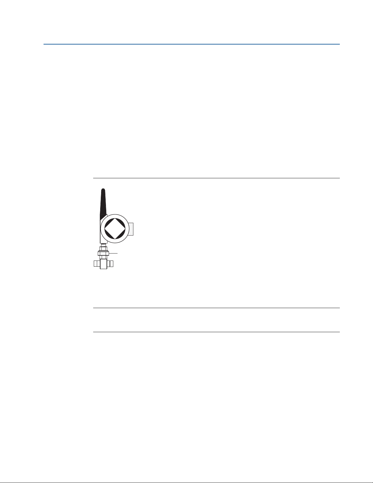
The antenna should be positioned vertically, either straight up or straight down, and it should be
approximately 3 ft. (1 m) from any large structure, building, or conductive surface to allow for
clear communication to other devices.
Figure 1-1. Antenna Position
2
Introduction
Page 11
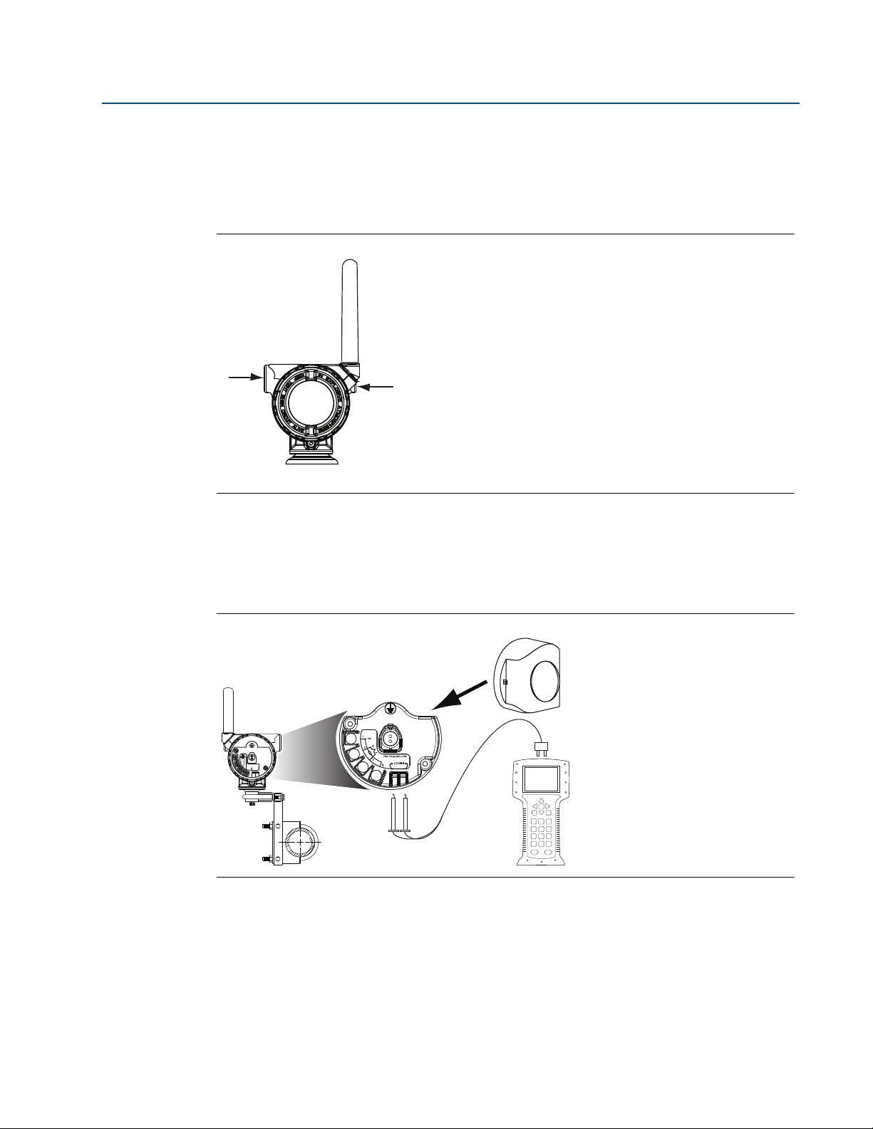
Reference Manual
COMM
P/N 00753-9200-0020
1
2
3
4
00809-0200-4705, Rev AA
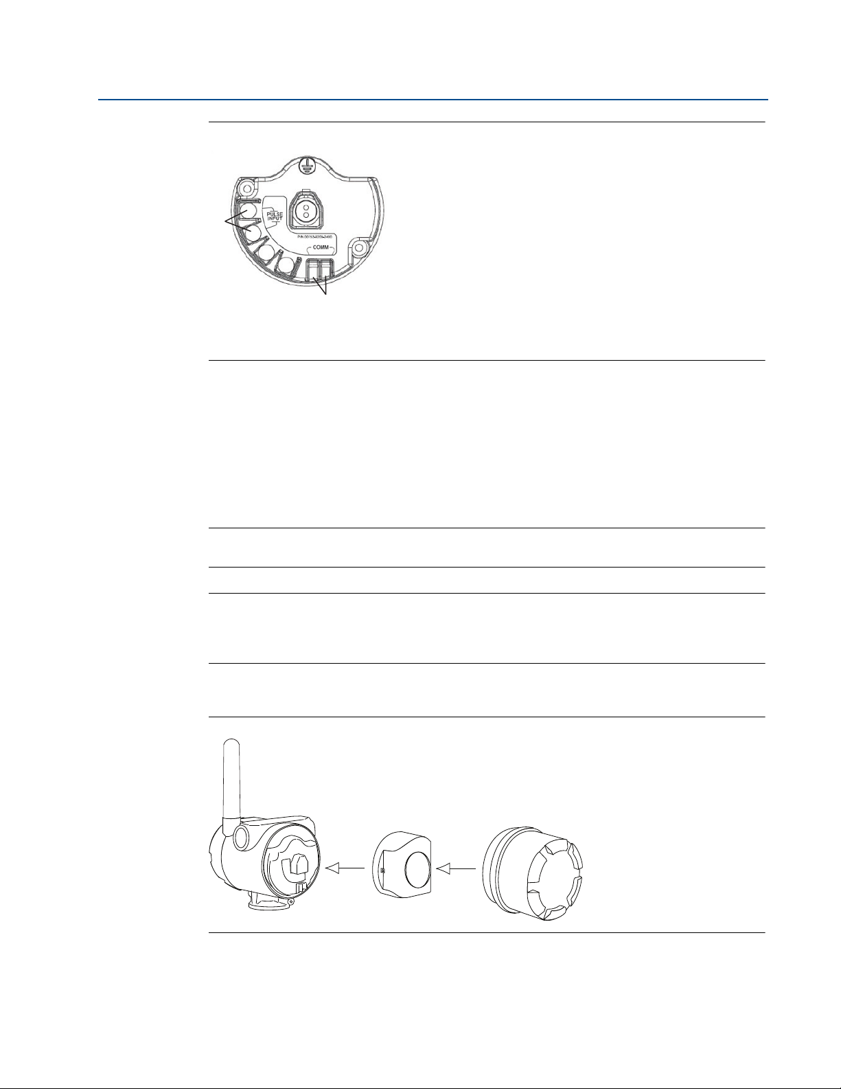
Preparing (or sealing) the conduit entries
Due to possible damage from moisture after installation, ensure that each conduit entry is
either sealed with a conduit plug with appropriate thread sealant, or has an installed conduit
fitting or cable gland with appropriate thread sealant.
Figure 1-2. Locating Conduit Entries
Section 1: Introduction
May 2015
A
A. Conduit entry
A
Connecting the Field Communicator to the transmitter
The power module needs to be connected for the Field Communicator to interface with the 705
Tra n sm it ter .
Figure 1-3. Field Communicator Connections
1.2.3 Choosing an installation location and position
When choosing an installation location and position, take into account access to the
transmitter. For best performance, the antenna should be vertical with space between objects in
a parallel metal plane, such as a pipe or metal framework, as the pipes or framework may
adversely affect the antenna’s performance.
Introduction
3
Page 12

Section 1: Introduction
May 2015
1.2.4 Electrical
Caring for the power module
The Rosemount 705 Wireless Totalizing Transmitter is self-powered. The included Black Power
Module contains two “C” size primary lithium/thionyl chloride batteries. Each battery contains
approximately 2.5 grams of lithium, for a total of 5 grams in each pack. Under normal
conditions, the battery materials are self-contained and are not reactive as long as the batteries
and the power module are maintained. Care should be taken to prevent thermal, electrical, or
mechanical damage. Contacts should be protected to prevent premature discharge.
Making turbine meter connections
Make turbine meter connections through the cable entry in the side of the connection head. Be
sure to provide adequate clearance for cover removal and lead attachments (remote option).
1.2.5 Verifying operating atmosphere
Verify the operating atmosphere of the transmitter is consistent with the appropriate hazardous
locations certifications.
Reference Manual
00809-0200-4705, Rev AA
Isolating the transmitter from sources of heat
The transmitter will operate within specifications for ambient temperatures between -40 and
185 °F (-40 and 85 °C). Heat from the process is transferred from the switch to the transmitter
housing. If the expected process temperature is near or beyond specification limits, consider
using an extension, or remote mount the transmitter to thermally isolate it from the process.
Temperature limits
Operating limit Storage limit
With LCD Display
Without LCD Display
-4 to 175 °F
-20 to 80 °C
-40 to 185 °F
-40 to 85 °C
-40 to 185 °F
-40 to 85 °C
-40 to 185 °F
-40 to 85 °C
4
Introduction
Page 13

Reference Manual
00809-0200-4705, Rev AA
1.3 Service support
To expedite the return process outside of North America, contact your Emerson Process
Management representative.
Within the United States, call the Emerson Process Management Response Center toll-free
number 1 800 654 7768. The center, which is available 24 hours a day, will assist you with any
needed information or materials.
The center will ask for product model and serial numbers, and will provide a Return Material
Authorization (RMA) number. The center will also ask for the process material to which the
product was last exposed.
Individuals who handle products exposed to a hazardous substance can avoid injury if they
are informed of, and understand, the hazard. If the product being returned was exposed to
a hazardous substance as defined by OSHA, a copy of the required Material Safety Data
Sheet (MSDS) for each hazardous substance identified must be included with the returned
goods.
Section 1: Introduction
May 2015
Shipping Wireless Products (Lithium Batteries):
The unit was shipped without the Power Module installed. Remove the Power Module from the
unit before shipping.
Primary lithium batteries (charged or discharged) are regulated during transportation by the
U.S. Department of Transportation. They are also covered by IATA (International Air Transport
Association), ICAO (International Civil Aviation Organization), and ARD (European Ground
Transportation of Dangerous Goods). It is the responsibility of the shipper to ensure compliance
with these or any other local requirements. Consult current regulations and requirements
before shipping.
1.4 Product recycling/disposal
Recycling of equipment and packaging should be taken into consideration. The product and
packaging should be disposed of in accordance with local and national legislation.
Introduction
5
Page 14

Section 1: Introduction
May 2015
Reference Manual
00809-0200-4705, Rev AA
6
Introduction
Page 15

Reference Manual
00809-0200-4705, Rev AA
Section 2 Configuration
Safety messages . . . . . . . . . . . . . . . . . . . . . . . . . . . . . . . . . . . . . . . . . . . . . . . . . . . . . . . . . . . . page 7
Connections are not polarity sensitive. . . . . . . . . . . . . . . . . . . . . . . . . . . . . . . . . . . . . . . . . page 8
Configuring the transmitter on the bench . . . . . . . . . . . . . . . . . . . . . . . . . . . . . . . . . . . . . . page 8
Joining the device to a network . . . . . . . . . . . . . . . . . . . . . . . . . . . . . . . . . . . . . . . . . . . . . . . page 10
2.1 Safety messages
Instructions and procedures in this section may require special precautions to ensure the safety
of the personnel performing the operations. Information that potentially raises safety issues is
indicated by a warning symbol ( ). Refer to the following safety messages before performing
an operation preceded by this symbol.
Section 2: Configuration
May 2015
2.1.1 Warnings
Failure to follow these installation guidelines could result in death or serious injury.
Only qualified personnel should perform the installation.
Explosions could result in death or serious injury.
Before connecting a Field Communicator in an explosive atmosphere, make sure that
the instruments are installed in accordance with intrinsically safe or non-incendive
field wiring practices.
Verify the operating atmosphere of the transmitter is consistent with the appropriate
hazardous locations certifications.
Electrical shock could cause death or serious injury.
Use extreme caution when making contact with the leads and terminals.
2.1.2 Connecting the turbine meter or pulse output device
The Rosemount 705 Wireless Totalizing Transmitter is compatible with a number of simple
turbine meters or pulse output devices. When ordered in the optional configuration for direct
connection, option code D1, the Rosemount 705 Transmitter is compatible with one inch
turbine meter direct connections. Figure 2-1 on page 8 shows the correct input connections to
the pulse terminals on the transmitter. To ensure a proper turbine meter connection, anchor the
turbine meter lead wires into the appropriate compression terminals and tighten the screws. In
noisy environments, be sure to properly ground the transmitter using the ground terminal.
7Configuration
Page 16

Section 2: Configuration
A
C
B
May 2015
Wiring the transmitter
For the R1 option (remote mount), if the turbine meter or pulse output device is installed in a
high-voltage environment and a fault condition or installation error occurs, the sensor leads and
transmitter terminals could carry lethal voltage. Use extreme caution when making contact
with the leads and terminals.
Use the following steps to wire the sensor and power supply to the transmitter:
1. Remove the transmitter enclosure cover.
2. Attach the turbine meter leads according to the diagram Figure 2-1 on page 8.
Note
For noisy electrical environments, it is best practice to ground the loop accordingly.
3. Connect the Black Power Module.
4. Verify the connection and power by viewing the LCD display and seeing the power up
Reference Manual
00809-0200-4705, Rev AA
sequence.
5. Replace the cover and tighten.
Figure 2-1. 705 Terminal Block
A. Pulse input connection
®
B. HART
C. Terminal block ground connection
terminal connection
Note
Connections are not polarity sensitive.
2.2 Configuring the transmitter on the bench
When using a Field Communicator, any configuration changes must be sent to the transmitter
8
using the Send key (F2). AMS Wireless Configurator configuration changes are implemented
when the Apply button is clicked.
Configuration
Page 17

Reference Manual
00809-0200-4705, Rev AA
Configuring on the bench with AMS Wireless Configurator
AMS Wireless Configurator is capable of connecting to devices directly, using a HART modem,
or with the Gateway. When configuring on the bench with a HART modem, double click the
device icon, then choose the Configure/Setup tab (or right click and select Configure/Setup).
Configure the device settings using the Direct Connection menu. When configuring with the
Gateway, double click the device icon then choose the Configure/Setup tab (or right click and
select Configure/Setup). Configure the device settings using the Wireless Connection menu.
To check or change sensor configuration using a Field Communicator, enter the following Fast
Key Sequence: 2, 1, 2.
2.3 Supported Engineering Unit Codes
The following engineering units are supported by the 705 totalizer.
Total Volume Volumetric Flowrate
US Gallons per Second
US Gallons per Minute
US Gallons
US Gallons per Hour
Section 2: Configuration
May 2015
Liters
Imperial Gallons
Cubic Meters
Cubic Yards
Cubic Inches
US Gallons per Day
Liters per Second
Liters per Minute
Liters per Hour
Imperial Gallons per Second
Imperial Gallons per Minute
Imperial Gallons per Hour
Imperial Gallons per Day
Cubic Meters per Second
Cubic Meters per Minute
Cubic Meters per Hour
Cubic Meters per Day
Cubic Yards per Second
Cubic Yards per Minute
Cubic Yards per Hour
Cubic Yards per Day
Cubic Inches per Second
Cubic Inches per Minute
Cubic Inches per Hour
Cubic Inches per Day
Configuration
Pulses
Hertz
9
Page 18

Section 2: Configuration
May 2015
If a custom volume unit is desired, the 705 totalizer can be configured to report the totalized
Pulses, and a custom conversion can be done on the host system side. Similarly, if a custom flow
rate unit is desired, the 705 totalizer can be configured to report pulses per second (“Hertz”),
and a custom conversion can be done on the host system side. When reporting Pulses or Hertz,
the configured K-factor has no affect on the reported values.
Configure units fast keys
Reference Manual
00809-0200-4705, Rev AA
Volume units fast keys
Flow units fast keys
2, 1, 2
2, 2, 1
2.4 Joining the device to a network
To communicate with the Gateway, and ultimately the Host System, the transmitter must be
configured to communicate with the wireless network.
Using a Field Communicator or AMS Wireless Configurator, enter the Network ID and Join Key so
they match the Network ID and Join Key of the Gateway and the other devices in the network. If
the Network ID and Join Key are not identical, the transmitter will not communicate with the
network. The Network ID and Join Key may be obtained from the Gateway on the Network>Set-
tings page on the web server or by clicking network information in the upper right hand corner.
Using a Field Communicator, the Network ID and Join Key can be configured using a Field
Communicator with the Fast Key Sequence: 2, 1, 3.
The final device network configuration piece is the Update Rate which, by default, is 1 minute. It
can be changed at commissioning, or at any time, by using AMS Wireless Configurator or the
Gateway’s web server. The Update Rate should be between 1 second and 60 minutes. To change
the Update Rate with a Field Communicator, use the Fast Key Sequence: 2, 1, 4.
If doing a bench top initial configuration, after completion remove the power module until
installation. When the device is installed, insert the power module and close the housing cover
securely. Always ensure a proper seal so that metal touches metal, but do not over tighten.
10
Configuration
Page 19

Reference Manual
00809-0200-4705, Rev AA
Section 3 Mounting
Safety messages . . . . . . . . . . . . . . . . . . . . . . . . . . . . . . . . . . . . . . . . . . . . . . . . . . . . . . . . . . . . page 11
Installing the transmitter . . . . . . . . . . . . . . . . . . . . . . . . . . . . . . . . . . . . . . . . . . . . . . . . . . . . page 12
LCD display . . . . . . . . . . . . . . . . . . . . . . . . . . . . . . . . . . . . . . . . . . . . . . . . . . . . . . . . . . . . . . . . . page 16
Grounding the transmitter . . . . . . . . . . . . . . . . . . . . . . . . . . . . . . . . . . . . . . . . . . . . . . . . . . . page 17
3.1 Safety messages
Instructions and procedures in this section may require special precautions to ensure the safety
of the personnel performing the operations. Information that potentially raises safety issues is
indicated by a warning symbol ( ). Refer to the following safety messages before performing
an operation preceded by this symbol.
Section 3: Mounting
May 2015
3.1.1 Warnings
Failure to follow these installation guidelines could result in death or serious injury.
Only qualified personnel should perform the installation.
Explosions could result in death or serious injury.
Before connecting a Field Communicator in an explosive atmosphere, make sure that
the instruments are installed in accordance with intrinsically safe or non-incendive
field wiring practices.
Verify the operating atmosphere of the transmitter is consistent with the appropriate
hazardous locations certifications.
Electrical shock could cause death or serious injury.
Use extreme caution when making contact with the leads and terminals.
This device complies with Part 15 of the FCC Rules. Operation is subject to the following
conditions: This device may not cause harmful interference. This device must accept any
interference received, including interference that may cause undesired operation.
This device must be installed to ensure a minimum antenna separation distance of 20 cm
from all persons.
Mounting
11
Page 20
Section 3: Mounting
May 2015
Reference Manual
00809-0200-4705, Rev AA
3.2 Installing the transmitter
The Rosemount 705 Wireless Totalizing Transmitter can be installed in one of two
configurations:
Direct Mount (D1): The turbine meter is connected directly to the 705 Transmitter housing’s
conduit entry. For installation instructions, see “Installing the transmitter in a direct mount
configuration” on page 12.
Remote Mount (R1): The turbine meter or pulse output device is mounted separate from the
705 Transmitter housing, then connected to the Rosemount 705 Transmitter via conduit. For
installation instructions, see “Installing the transmitter in a remote mount configuration” on
page 14.
3.2.1 Installing the transmitter in a direct mount configuration
Figure 3-1. Direct Mount
B
C
A
A. Turbine meter
B. 705 Transmitter
C. 1-in. NPT connection to flow meter and 2 piece pipe union
Note
Direct mount installation should not be employed when using tubing and connectors such as
Swagelok® fittings.
1. Install the turbine meter according to standard installation practices making sure to use
thread sealant on all of the connections.
2. Attach the turbine meter wiring to the terminals as indicated on the wiring diagram
(Figure 3-2). This procedure is already included for the D1 (direct mount) option.
12
Mounting
Page 21
Reference Manual
A
C
B
00809-0200-4705, Rev AA
Figure 3-2. 705 Terminal Block
A. Pulse input connection
B. HART terminal connection
C. Terminal block ground connection
3. Attach the transmitter housing to the turbine meter using the threaded conduit entry.
4. Seal threads on 1-in. NPT turbine meter connection. Take union apart and turn on
Section 3: Mounting
May 2015
bottom fitting to turbine meter.
5. Attach mill spec connector to turbine meter pickup.
6. Screw on the remaining union part.
Note
Sealant should already be applied to threads on the D1 (direct mount) option.
Note
Wireless devices should only be powered up after the Smart Wireless Gateway, in order of
proximity from the Smart Wireless Gateway beginning with the closest device. This results in a
simpler and faster network installation.
7. Connect the Black Power Module
Figure 3-3. Power Module Installation
8. Close the housing cover and tighten to safety specification. Always ensure a proper seal
so that metal touches metal, but do not over tighten.
9. Position the antenna so it is vertical, either straight up or straight down.
Mounting
13
Page 22
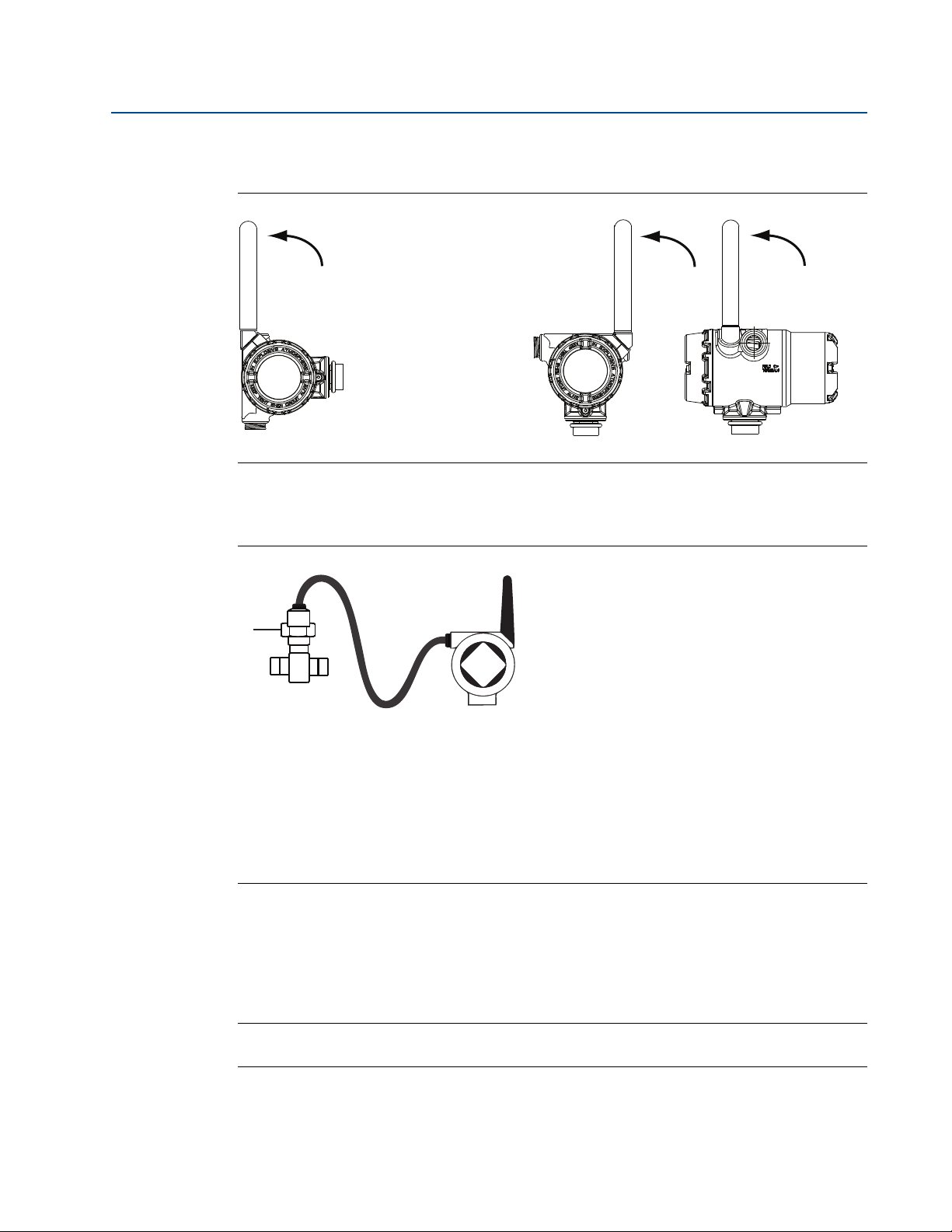
Section 3: Mounting
Possible antenna rotation shown.
Antenna rotation allows for best
installation practices in any
configuration.
A
B
C
May 2015
Reference Manual
00809-0200-4705, Rev AA
a. The antenna should be approximately 3-ft. (0.91 m) from any large structures or
buildings, to allow clear communication to other devices.
Figure 3-4. Antenna Positioning
3.2.2 Installing the transmitter in a remote mount configuration
Figure 3-5. Remote Mount Installation
A. Turbine meter
B. Rosemount 705 Transmitter
C. 1-in. supplied cable gland adaptor for turbine meter.
Included:
(1) Cable gland
(1) Cable gland adaptor for turbine meter
10 ft. of cable connection wiring
1. Install the turbine meter or pulse output device according to standard installation
practices being sure to use thread sealant on all of the connections.
2. Pull the cable connection wiring through the supplied cable gland adaptor for the
turbine meter. Then pull the cable wiring through the transmitter cable gland.
Note
Pay attention to the orientation of the cable gland to ensure proper connection to transmitter.
3. Attach the turbine meter or pulse output device wiring to the terminals as shown in the
14
wiring diagrams beginning on page 8.
Mounting
Page 23

Reference Manual
00809-0200-4705, Rev AA
Note
Wireless devices should only be powered up after the Smart Wireless Gateway, in order of
proximity from the Gateway beginning with the closest device. This results in a simpler and
faster network installation
4. If commissioning the 705 Transmitter, connect the power module as shown in Figure
3-3 on page 13.
5. Close the housing cover and tighten to safety specifications. Always ensure a proper
seal by installing the electronic housing covers so that metal touches metal, but do not
over tighten.
6. Position the antenna vertically, either straight up or straight down, as shown in Figure
3-4 on page 14.
a. The antenna should be approximately 3 ft. (1 m) from any large structures or
buildings, to allow clear communication to other devices.
3.3 Remote antenna (optional)
Section 3: Mounting
May 2015
The remote antenna option provides flexibility for mounting the Rosemount 705 Totalizer based
on wireless connectivity, lightning protection, and current work practices.
When installing remote mount antennas for the transmitter, always use established safety
procedures to avoid falling or contact with high-power electrical lines.
Install remote antenna components for the transmitter in compliance with local and
national electrical codes and use best practices for lightning protection.
Before installing, consult with the local area electrical inspector, electrical officer, and work
area supervisor.
The transmitter remote antenna option is specifically engineered to provide installation
flexibility while optimizing wireless performance and local spectrum approvals. To maintain
wireless performance and avoid non-compliance with spectrum regulations, do not change
the length of cable or the antenna type.
If the supplied remote mount antenna kit is not installed per these instructions, Emerson
Process Management is not responsible for wireless performance or non-compliance with
spectrum regulations.
The remote mount antenna kit includes coaxial sealant that is for the cable connections,
lightning arrestor, and antenna.Find a location where the remote antenna has optimal wireless
performance. Ideally this will be 15-25 ft. (4.6 - 7.6 m) above the ground or 6 ft. (2 m) above
obstructions or major infrastructure. To install the remote antenna, use one of the following
procedures. The WN option is 25 ft. (7.6 m).
Mounting
15
Page 24

Section 3: Mounting
May 2015
3.3.1 WN remote antenna option
1. Mount the antenna on a 1.5-2 in. pipe mast using the supplied mounting equipment.
2. Connect the lightning arrestor directly to the top of the Rosemount 705 Totalizer.
3. Install the grounding lug, lock washer, and nut on top of lightning arrestor.
4. Connect the antenna to the lightning arrestor using the supplied LMR-400 coaxial cable
ensuring the drip loop is not closer than 1 ft. (0.3 m) from the lightning arrestor.
5. Use the coaxial sealant to seal each connection between the wireless field device,
lightning arrestor, cable, and antenna.
6. Ensure the mounting mast and lightning arrestor are grounded according to
local/national electrical code.
Note
Any spare lengths of coaxial cable should be placed in 12 in. (0.3 m) coils.
Reference Manual
00809-0200-4705, Rev AA
3.4 LCD display
If an LCD display is ordered, it will be shipped attached to the transmitter.
The optional LCD display can be rotated in 90-degree increments by squeezing the two tabs,
pulling out, rotating and snapping back into place.
If the LCD pins are inadvertently removed from the interface board, carefully re-insert the pins
before snapping the LCD display back into place.
Installing the LCD display
To install the LCD display, use Figure 3-6 on page 17 and the following instructions:
1. Remove the LCD cover. Do not remove the instrument cover in explosive environments
when the circuit is live.
2. Put the four-pin connector into the LCD display, rotate to the desired position and snap
into place.
Note the following LCD display temperature limits:
Operating: -4 to 175 °F (-20 to 80 °C)
Storage: -40 to 185 °F (-40 to 85 °C)
16
3. Replace the transmitter cover.
Note
Only use Rosemount Wireless LCD display part number: 00753-9004-0002. The transmitted
data may not match data displayed on LCD due to differences in update rate and screen refresh
rate.
Mounting
Page 25

Reference Manual
A
C
B
00809-0200-4705, Rev AA
Figure 3-6. Optional LCD Display
A
B
A. LCD pins
B. LCD display
C. LCD cover
C
3.5 Grounding the transmitter
The Rosemount 705 Transmitter operates best with the housing grounded. Floating systems,
however, can cause extra noise that may affect the accuracy of the Rosemount 705 Totalizer. If
the signal appears noisy or erratic, grounding at a single point may solve the problem.
Grounding of the electronics enclosure should be done in accordance with local and national
installation codes. Grounding is accomplished through the process connection using the
internal or external case grounding terminal.
Section 3: Mounting
May 2015
Determining grounding requirements
Each process installation has different grounding requirements. Use the options recommended
by the facility for the specific turbine meter or pulse output device.
1. Connect turbine meter wiring shield to the grounded transmitter housing.
2. Ensure the transmitter housing is electrically isolated from the turbine meter or pulse
output device wiring.
A. Turbine meter
B. Rosemount 705 Transmitter
C. Transmitter ground point
Mounting
17
Page 26

Section 3: Mounting
May 2015
Reference Manual
00809-0200-4705, Rev AA
18
Mounting
Page 27

Reference Manual
00809-0200-4705, Rev AA
Section 4 Commissioning
Safety messages . . . . . . . . . . . . . . . . . . . . . . . . . . . . . . . . . . . . . . . . . . . . . . . . . . . . . . . . . . . . page 19
Configuring the transmitter to communicate with the wireless network . . . . . . . . . . . page 20
Using AMS Wireless Configurator to configure the transmitter . . . . . . . . . . . . . . . . . . . . page 21
Using a Field Communicator to change parameters within the device . . . . . . . . . . . . . page 21
Verifying operation . . . . . . . . . . . . . . . . . . . . . . . . . . . . . . . . . . . . . . . . . . . . . . . . . . . . . . . . . page 23
4.1 Safety messages
Instructions and procedures in this section may require special precautions to ensure the safety
of the personnel performing the operations. Information that potentially raises safety issues is
indicated by a warning symbol ( ). Refer to the following safety messages before performing
an operation preceded by this symbol.
Section 4: Commissioning
May 2015
4.1.1 Warnings
Failure to follow these installation guidelines could result in death or serious injury.
Make sure only qualified personnel perform the installation.
Explosions could result in death or serious injury.
Before connecting a Field Communicator in an explosive atmosphere, make sure the
instruments are installed in accordance with intrinsically safe or non-incendive field
wiring practices.
Verify the operating atmosphere of the transmitter is consistent with the appropriate
hazardous locations certifications.
Electrical shock could cause death or serious injury.
Use extreme caution when making contact with the leads and terminals.
Note
The Rosemount 705 Wireless Totalizing Transmitter and all other wireless devices should be
installed only after the Gateway has been installed and is functioning properly.
Wireless devices should be powered up in order of proximity from the Gateway, beginning with
the device closest to the Gateway. This will result in a simpler and faster network installation.
Commissioning
19
Page 28

Section 4: Commissioning
May 2015
Reference Manual
00809-0200-4705, Rev AA
4.2 Configuring the transmitter to communicate with the wireless network
In order to communicate with the Smart Wireless Gateway, and ultimately the Host System, the
transmitter must be configured to communicate with the wireless network. This step is the
wireless equivalent of connecting wires from a transmitter to the Host System. Using a Field
Communicator or AMS
match the Network ID and Join Key of the gateway and other devices in the network. If the
Network ID and Join Key are not identical, the 705 Transmitter will not communicate with the
network. The Network ID and Join Key may be obtained from the Smart Wireless Gateway on
the Setup>Network>Settings page on the web server, shown in Figure 4-1.
Figure 4-1. Gateway Network Settings
®
Wireless Configurator, enter the Network ID and Join Key so that they
20
Commissioning
Page 29

Reference Manual
00809-0200-4705, Rev AA
Section 4: Commissioning
May 2015
4.3 Using AMS Wireless Configurator to configure the transmitter
1. Right click on the Rosemount 705 Transmitter and select Configure.
2. When the menu opens, select Join Device to Network and follow the method to enter
the Network ID and Join Key.
4.4 Using a Field Communicator to change parameters within the device
The most common parameters changed are the Network ID and Join Key. The Network ID and
Join Key may be changed in the wireless device by using the following Fast Key sequence. Set
both Network ID and Join Key.
Func tion Key sequence Menu items
Wireless Setup
2, 1, 1 Network ID, Set Join Key
4.5 K-Factor consideration
The K-factor value is used to tell the 705 Totalizer how much volume corresponds to an input
pulse. The K-factor is entered in units of “Pulses per Gallon”. It is important to configure the 705
Totalizer with the proper K-factor that corresponds to the turbine meter that it is attached to. If
the K-factor is not configured properly, the accuracy of the reported totalized volume and flow
rate may be adversely affected. Any time the attached turbine meter is replaced, the K-factor
setting should be verified and/or modified accordingly to maintain a proper match.
If the K-factor is not specified to be pre-configured when ordering the 705 Totalizer, it will be
shipped without any K-factor configured. In this case, the K-factor must be configured before
any valid values can be obtained for the totalized volume or the average flow rate. The 705
Totalizer will report a value of NaN (”Not a Number”) when the K-factor has not been
configured.
When changing the K-factor, the 705 Totalizer will recalculate a new totalized volume assuming
that all captured input pulses correspond to the new K-factor value. This means that the current
value of the totalized volume held in the 705 Totalizer may change as a result of changing the
K-factor. If this is not desired, the value of totalized volume can be noted, and reset the volume
to the original value after the new K-factor has been configured. To avoid any loss of volume
accumulation, this procedure should only be done when the flow through the attached turbine
meter has been stopped.
Commissioning
21
Page 30

Section 4: Commissioning
1 Refresh Alert s
2 No Active Alerts
3History
4F:
5A:
6M:
1 Alert Description
2Alert Image
1 Identi fication
2 Revisions
3Radio
4 Sec urity
1 Model Number 1
2 Model Number 2
3 Model Number 3
1 Long Tag
2Tag
3 Model
4 Transmitter S. N.
5Date
6 Desc ription
7Message
8 Model Numbers
9 Device Image
1Universal
2Field Device
3Software
4 Hardware
5 DD Revisio n
1Overview
2 Configure
3 Service Tools
1MAC Address
2 Manufac turer
3 Device Type
4 Device Revision
5 Software Revision
6 Hardware Revision
7Xmit Power Level
8 Min Brdcst Rate
1 Wri te Protect St atus: Disabled
2 Lock Status: Unloc ked
3 Over the Air Upgrade: Unloc ked
1 Guided S etup
2Manual Setup
3 Alert Setup
1Basic Setup
2 Configure Totalizing Opt ions
3 Join Device to N/W
4 Configure Update Rate
5 Configure Device Display
6 Configure Proces s Alerts
1Wireless
2 Totaliz ing Options
3 Dis play
4HART
5 Sec urity
6 Device Information
7 Power
1Network ID
2 Join Device to N/W
3 Broadcas t Info
1 Turbine Configuration
2 Flow Configuration
1k-factor
2 Volume Unit s
3 Roll Over Point
4 Input Sens itivity
1 Flow Units
2 Low Flow Cutoff
3 Filt er Period
1Display Mode
2Display Options
1 Totalized V olume
2 Average Flow Rate
3Electronics Temp
4 Supply Voltage
5 Percent of Range
1 Primary Variable
2 Secondary Variable
3 Third Variable
4 Fourth V ariable
1 Meas and S tatus log
2 Config Data Hist ory
3 Variable M apping
4 Percent Range
1 Upper Range Value
2 Lower Range Value
3 Upper Sensor Lim it
4 Lower Sensor Lim it
1 Write Protect Status
2 Lock Stat: Unlock ed
3Lock/Unlock
4 Over the Air Upgrade
1 Long Tag
2Tag
3 Transmit ter S. N.
4Date
5Description
6 Mes sage
1 Power Mode
2 Power Sourc e
1 Totaliz ed Volume
2 Average Flow Rate
3 Alert Options
1Mode
2Units
3Alert Limit
4 Dead Band
1 Totaliz ed Volume
2Status
3HI-HI Alarm
4HI Alarm
5 LO-LO Alarm
6LO Alarm
/Avg Flow Rate
1 Roll Over Point
2 Roll Over Exceeded
3 Roll Over Warning
4 Lifetim e Warning
5 Roll Over Warn Thres
6 Lifetim e Warn Thres
1Alerts
2 V ariables
3 Trends
4 Communications
5 M aintenace
6Simulate
1 Refresh Alerts
2 No Active Alerts
3History
1 Clear Alert History
2 List of Previous alerts
1PV
2SV
3TV
4QV
1 PV / SV / TV / QV
2 PV / SV/ TV / QV Status
3 Gauge
1 Variabl e Summary
2 Mapped Vari ables
3 All Variables
4 Last Update Time
1 Totaliz ed Volume
2 Average Flow Rate
3 Elec tronics Temp
4 Supply Voltage
5 Perc ent of Range
1 Totalized V olume
Average Flow Rate
Electronic s Temp
Supply Voltage
Percent of Range
2 Status
3 Gauge
1 Totaliz ed Volume
2 Average Flow Rate
3 Data His tory
1 Device Variable
2 Variable Uni ts
3 Sampl e Interval
4 Date of Newest V al
5Time of Newest Val
6 Vi ew Data History
7Refresh
1 Comm: Connected
2 Join Mode
3 Available Nghbrs
4 Advertis ements
5 Join Attempts
1 Routine M aintenance
2 Reset/Restore
1 Measurem ent History
2 Locat e Device
3 Inst all New Power Mod ule
4Set Total Volume
5 Sens or Life
1Lifetime Counts
2 Reset Lifetime Cnts
1Device Reset
2 Restore to Default Settings
1 S imulate
1 Totalized Volume
2 Average Flow Rate
3 Elec tronics Temperature
4 Supply Voltage
1 Dev Status : Good
2 Com m:Connected
3 Totaliz ed Volume
4Status
5 Average Flow Rate
6Status
7 Update Rat e
8 Join Device to N/ W
9 De vice Info rmat ion
May 2015
Figure 4-2. Handheld Tree
Reference Manual
00809-0200-4705, Rev AA
22
Commissioning
Page 31

Reference Manual
i d - 1 2
3 4 5 6 7 8
n e t w k
13 0 5
I D
S u p l y
7. 2 1
v o l t s
00809-0200-4705, Rev AA
4.6 Verifying operation
There are four ways to verify operation: using the optional local display (LCD), using the Field
Communicator, using the Smart Wireless Gateway's integrated web interface, or by using AMS
Suite Wireless Configurator. If the Rosemount 705 transmitter was configured with the Network
ID and Join Key, and sufficient time has passed, the transmitter will be connected to the
network.
Troubleshooting
If the device is not joined to the network after power up, verify the correct configuration of the
Network ID and Join Key, and verify that Active Advertising has been enabled on the Gateway.
The Network ID and Join Key in the device must match the Network ID and Join Key of the
Gateway.
Operating the local display
The LCD displays the configured values at the update rate, or can optionally be enabled for
continuous display. See Section 5.1.2.
Section 4: Commissioning
May 2015
Diagnostic button display sequence
More detailed diagnostic information can be obtained by removing the display cover of the
Rosemount 705 Transmitter, and momentarily depressing the DIAG button. The LCD will display
the diagnostic screens as shown in Figure 4-4.
Press the Diagnostic button to display the TAG, Device ID, Software Revision, Network ID,
Network Join Status and Device Status screens.
Figure 4-3. Diagnostic Screen Sequence
Tag Device ID Network ID
A b c d e
f g h
Network join
status
n e t w k
O K
Device status
Network join status
Commissioning
The chevron-shaped status bar at the top of the screen indicates the progress of the network
join process. When the status bar is filled, the device is successfully connected to the wireless
network. This is shown, in Figure 4-4 on page 24.
23
Page 32

Section 4: Commissioning
N E T w K
S R C H N G
May 2015
Figure 4-4. Network Join Status Screens
Reference Manual
00809-0200-4705, Rev AA
Searching for
network
Joining network
n e t w k
N E G O T
Connected with
limited bandwidth
n e t w k
L I M - O P
Connected
n e t w k
O K
Connecting with a Field Communicator
A 705 DD is required for HART® communication.
Func tion Key sequence Menu items
Communications
2, 1, 3 Join Status, Communication Status, Join Mode, Number of
Available Neighbors, Number of Advertisements Heard,
Number of Join Attempts
Checking for communication using the Smart Wireless Gateway
In the integrated web interface from the Gateway, navigate to the devices page. This page
shows whether the device has joined the network and if it is communicating properly.
Note
The time to join the new device(s) to the network is dependent upon the number of devices
being joined and the number of devices in the current network. For one device joining an
existing network with multiple devices, it may take up to five minutes. It may take up to 60
minutes for multiple new devices to join the existing network.
24
Commissioning
Page 33

Reference Manual
00809-0200-4705, Rev AA
4.6.1 AMS Wireless Configurator
When the device has joined the network, it will appear in the Device Manager as illustrated
below.
Section 4: Commissioning
May 2015
Troubleshooting
If the device is not joined to the network after power up, verify the correct configuration of the
Network ID and Join Key, and verify that Active Advertising has been enabled on the Gateway.
The Network ID and Join Key in the device must match the Network ID and Join Key of the
Gateway.
The Network ID and Join Key may be obtained from the Gateway in the upper right hand corner
labeled network information. The Network ID and Join Key may be changed in the wireless
device by using the following Fast Key sequence.
Func tion Key sequence Menu items
Wireless
2,1,3 Join Device to Network
Commissioning
25
Page 34

Section 4: Commissioning
May 2015
Reference Manual
00809-0200-4705, Rev AA
26
Commissioning
Page 35

Reference Manual
00809-0200-4705, Rev AA
Section 5: Operation and Maintenance
Section 5 Operation and Maintenance
Basic operation . . . . . . . . . . . . . . . . . . . . . . . . . . . . . . . . . . . . . . . . . . . . . . . . . . . . . . . . . . . . . . page 27
Determining device health . . . . . . . . . . . . . . . . . . . . . . . . . . . . . . . . . . . . . . . . . . . . . . . . . . . . page 28
Interpreting LCD screen messages . . . . . . . . . . . . . . . . . . . . . . . . . . . . . . . . . . . . . . . . . . . . . page 29
Replacing the power module . . . . . . . . . . . . . . . . . . . . . . . . . . . . . . . . . . . . . . . . . . . . . . . . . . page 36
Modbus®, EtherNet/IP and OPC mapping . . . . . . . . . . . . . . . . . . . . . . . . . . . . . . . . . . . . . . . page 37
5.1 Basic operation
5.1.1 Rollover information
The totalized volume will automatically restart at a volume of zero when the configured rollover
point has been reached. The table below describes some estimates to how long a rollover will
take at max values of 10,000,000.00. Best practices are to reset the total before the device
rollover occurs. The totalized volume will accumulate in the transmitter up to a configurable
rollover point.Once the totalized volume reaches the rollover point, the totalized value will
automatically continue totalizing the volume starting from zero. The rollover point defaults to
100 Million, but can be configured to any value between 1 and 2 Billion. Note that the resolution
of the totalized volume is reduced as the value gets larger. refer to the table below or see the
menu tree
May 2015
Configured units
code
Cu.M 75 Years 137 Days 39 Minutes
L 27 Days 3 Hours 2 Seconds
UK Gal 125 Days 15 Hours 10 Seconds
US Gal 104 Days 12 Hours 9 Seconds
Barrel 11 Years 21 Days 6 Minutes
Cu.F 2 Years 3 Days 1 Minute
Cu.Y 57 Years 105 Days 30 Minutes
Cu.I 0 Days 3 Minutes 0 Seconds
Pulses 1 Day 50 Seconds 0 Seconds
Note
The rollover value itself is not affected by the volume engineering units. For example, if the
rollover value is configured to 100 Million with engineering units of gallons, a change to volume
units of cubic meters will cause the rollover value to still be 100 Million, but will rollover at 100
Million Cubic meters rather than 100 Million gallons.
Earliest rollover
Typical longest LCD
wait
Typical longest value
wait
Operation and Maintenance
27
Page 36

Section 5: Operation and Maintenance
May 2015
5.1.2 Enabling the LCD continuous operation feature
The Rosemount 705 Wireless Totalizing Transmitter has the ability to keep the LCD always on for
local indication of the total volume and average flow for the attached output device. Power
module life will be reduced when operating in this mode. For example, at a 1-minute update
rates the power module life would be reduced from a 10 year life to an estimated 8 year life.
More information on the power module life impact for various update rates can be found at
http://www3.emersonprocess.com/rosemount/PowerModuleLifeCalculator/Default.aspx
Enabling continuous LCD updates
AMS® Wireless Configurator or Device Manager
1. Connect the Rosemount 705 to the HART® communicator and access the Rosemount
705 DD.
2. Double click on the Rosemount 705 icon and select Configure>Guided Setup> Configure
Device Display
Through the handheld
Reference Manual
00809-0200-4705, Rev AA
1. Connect the Rosemount 705 to the HART Handheld device.
2. Fast keys 2, 1, 5
a. Configure>Manual Setup> Display> Display Mode
5.2 Determining device health
In addition, system considerations must be observed to ensure that the device is still connected
to the wireless network and reporting values. On an Emerson Smart Wireless Gateway, this can
be done by referring to the parameter: PV_HEALTHY. The PV_HEALTHY has a “True” state when
the device is on the network and its updates are current, not late or stale, and the PV value is
functioning properly. A “False” state of PV_HEALTHY means that the device is either off of the
network, the data updates are not current, or that there is an issue measuring PV. In the case of a
“False” state of PV_HEALTHY, it is recommended to assume that the device is not connected to
the network and to take appropriate action.
28
Operation and Maintenance
Page 37

Reference Manual
X X X X X
X X X X x x x
x x x x x x
00809-0200-4705, Rev AA
Section 5: Operation and Maintenance
5.3 Interpreting LCD screen messages
The transmitted data may not match data displayed on LCD display due to differences in update
rate and screen refresh rate.
5.3.1 Startup screen sequence
The following screens will display when the power module is first connected to the 705
Tr an sm i tt er.
1. All Segments On: used to visually
determine if there are any bad
segments on the LCD display
May 2015
A b c d e
f g h
2. Device Identification: used to
determine Device Type
3. Device Information - Tag: user
entered tag which is 8 characters
long - will not display if all characters
are blank
4. Totalized Volume Screen:
accumulated total volume over time
Operation and Maintenance
29
Page 38

Section 5: Operation and Maintenance
May 2015
Reference Manual
00809-0200-4705, Rev AA
5. Average Rate Screen: average rate
value
6. Electronics Screen: feature board
temperature value, can be modified
to a specific variable in the DD
S u p l y
7. 2 1
v o l t s
a l e r t
p r e s n t
7. Supply Voltage Screen: voltage
reading at the power module
terminals, can be modified to a
specific variable in the DD
8. Alert Screen: at least one alert is
present - this screen will not display
if no alerts are present
30
Operation and Maintenance
Page 39

Reference Manual
00809-0200-4705, Rev AA
Section 5: Operation and Maintenance
5.3.2 Diagnostic button screen sequence
The following five screens will display when the device is operating properly and the Diagnostic
Button has been pressed.
May 2015
A b c d e
f g h
i d - X X
X X X X X X
1. Device Information - Tag: user
entered tag which is 8 characters
long - will not display if all characters
are blank
2. Device Identification: used to
determine Device ID
3. Software Revision: indication of the
software revision of the device
13 0 5
7. 2 1
Operation and Maintenance
n e t w k
I D
n e t w k
O K
S u p l y
v o l t s
4. Network ID: assuming the device
has the correct join key, this ID tells
the user what network the device
can connect with
5. Network Connection Status: the
device has joined a network and has
been fully configured and has
multiple parents
6. Supply Voltage: voltage reading at
the power module terminals
31
Page 40

Section 5: Operation and Maintenance
May 2015
5.3.3 Network connection status screens
These screens display the network status of the device. Only one will be shown in the fourth
position of the diagnostic button screen sequence.
Reference Manual
00809-0200-4705, Rev AA
n e t w k
u n k n w n
n e t w k
I N I T
n e t w k
i d l e
Diagnostic Button Screen 4.1: the device is
attempting to start the radio
Diagnostic Button Screen 4.2: the device
has just restarted
Diagnostic Button Screen 4.3: the device is
starting to join the process
32
n e t w k
D I S C N T
N E T w K
S R C H N G
Diagnostic Button Screen 4.4: the device is
in a disconnected state and requires a “Force
Join” command to join the network
Diagnostic Button Screen 4.5: the device is
searching for the Network
Operation and Maintenance
Page 41

Reference Manual
00809-0200-4705, Rev AA
Section 5: Operation and Maintenance
May 2015
n e t w k
N E G O T
n e t w k
c o n e c t
n e t w k
L I M - O P
Diagnostic Button Screen 4.6: the device is
attempting to join a network
Diagnostic Button Screen 4.7: the device is
connected to the Network, but is in a
“Quarantined” state
Diagnostic Button Screen 4.8: the device is
joined and operational, but is running with
limited bandwidth for sending periodic data
Operation and Maintenance
n e t w k
O K
Diagnostic Button Screen 4.9: the device
has joined a network and has been fully
configured and has multiple parents
33
Page 42

Section 5: Operation and Maintenance
May 2015
5.3.4 Device diagnostic screens
The following screens will show the device diagnostics depending on the state of the device,
continuing after Diagnostic Button Screen 5.
Reference Manual
00809-0200-4705, Rev AA
Diagnostic Button Screen 6.1: there is a
critical error which may prevent the
electronics board from operating correctly
Diagnostic Button Screen 6.2: there is a
warning which should be addressed, but
should not affect the device output
s u p l y
f a i l u r
s u p l y
l o w
r a d i o
f a i l u r
Diagnostic Button Screen 7.1: terminal
voltage has dropped below level of operating
limit. Replace the Black Power Module model
number 701PBKKF
(Part Number: 00753-9220-0001)
Diagnostic Button Screen 7.2: terminal
voltage is below the recommended
operating range - if this is a self-operated
device, the power module should be replaced
- for line powered devices, the supply voltage
should be increased
Diagnostic Button Screen 8: device cannot
retrieve information from the radio in the
device - the device may still be operational
and publishing HART data
34
Operation and Maintenance
Page 43

Reference Manual
00809-0200-4705, Rev AA
c o n f g
f a i l u r
s n s r
f a i l u r
Section 5: Operation and Maintenance
May 2015
Diagnostic Button Screen 9: configuration
of the transmitter is invalid such that critical
operation of the device may be affected check the extended configuration status to
identify which configuration item(s) need to
be corrected
Diagnostic Button Screen 10: switch
attached to the transmitter has failed, and
valid readings from that switch are no longer
possible - check the switch and switch wiring
connections - check additional status for
more detailed information of the failure
source
b d W T h
Diagnostic Button Screen 11: device has not
yet received all of the requested wireless
bandwidth needed to operate as configured
l i m i t d
Note
Use Rosemount Wireless LCD display part number: 00753-9004-0002.
Operation and Maintenance
35
Page 44

Section 5: Operation and Maintenance
May 2015
5.4 Replacing the power module
When the power module needs to be replaced, remove the power module cover and the
depleted power module. Replace the power module with a new Black Power Module,
SmartPower
replace the cover and tighten it to specification. Always ensure a proper seal so metal touches
metal, but do not over-tighten. After the power module has been replaced, navigate to AMS
Wireless Configurator to reset the power module function. This also can be done via the
handheld 3, 5, 1, 3.
When replacing the power module, the device will stop totalizing data. The device will
resume from where the last total was periodically recorded (within a 5 minute window).
Example: The best practice when replacing the power module is to make note of the
totalized volume before removing the power module. After installing a new power module,
the totalized volume can be set to the previous recorded value.
™
Solutions model number 701PBKKF (part number 00753-9220-0001). Then
Reference Manual
00809-0200-4705, Rev AA
Handling the power module
The Black Power Module with the wireless unit contains two “C” size primary lithium/thionyl
chloride batteries. Each battery contains approximately 2.5 grams of lithium, for a total of 5
grams in each pack. Under normal conditions, the battery materials are self-contained and are
not reactive as long as the batteries and the battery pack integrity are maintained. Care should
be taken to prevent thermal, electrical or mechanical damage. Contacts should be protected to
prevent premature discharge.
Use caution when handling the power module, it may be damaged if dropped from heights in
excess of 20 feet.
Battery hazards remain when cells are discharged.
Environmental considerations
As with any battery, local environmental rules and regulations should be consulted for proper
management of spent batteries. If no specific requirements exist, recycling through a qualified
recycler is encouraged. Consult the materials safety data sheet for battery specific information.
Shipping considerations
The unit was shipped to you without the power module installed. Remove the power module
prior to shipping.
36
Each power module contains two “C” size primary lithium batteries. Primary lithium batteries
are regulated in transportation by the U.S. Department of Transportation, and are also covered
by International Air Transport Association (IATA), International Civil Aviation Organization
(ICAO), and European Ground Transportation of Dangerous Goods (ARD). It is the responsibility
of the shipper to ensure compliance with these or any other local requirements. Consult current
regulations and requirements before shipping.
Operation and Maintenance
Page 45

Reference Manual
00809-0200-4705, Rev AA
Section 5: Operation and Maintenance
5.5 Modbus®, EtherNet/IP and OPC mapping
Following is a table of parameters that can be used for Modbus, EtherNet/IP and OPC mapping.
These parameters are used by the Smart Wireless Gateway and can be found in the web
interface of the Gateway. Some of these parameters are analog values and some are discrete,
and this is noted in the description. The Setpoint parameters are used to drive the output
channel and for the readback of the state of the output channel.
Parameters for Modbus, EtherNet/IP, and OPC Mapping
Parameter name Description Read/Write
May 2015
SUPPLY_VOLTAGE Maps the supply voltage of the device. For
monitoring the health of your power module use
SUPPLY_VOLTAGE_HEALTHY
ELECTRONICS_TEMPERATURE Maps the electronics temperature Read
TOTALIZED_VOLUME Maps the totalized volume that the device has
measured
AVE RAG E_ FLOW _R ATE Maps the instantaneous flow rate over that period
of time set by the DD
ACCUMULATOR_RESET Use this parameter to reset the number of total
counts on the device
ACCUMULATOR_STATE What is the current totalized value of the device Read
Read
Read
Read
Write
Mapping the Rosemount 705 parameters
Below is the Gateway screen where the accumulator reset, accumulator state, totalized_
volume, average_flow variables and parameter can be mapped. This is important to understand
how to reset the totalized volume of the device via Modbus, OPC, or EtherNet/IP
Figure 5-1. Smart Wireless Gateway Modbus Register Map
™
.
Operation and Maintenance
37
Page 46

Section 5: Operation and Maintenance
May 2015
To reset the total of the 705 via Modbus, follow the steps below.
1. Navigate to Modbus connection.
2. Map 705.Accumulaor_Reset.
3. Submit.
To reset the total of the 705 via OPC, follow the steps below.
1. Navigate to OPC connection.
2. Map 705.Accumulaor_Reset.
3. Submit.
To reset the total of the 705 via EtherNet/IP, follow the steps below.
1. Navigate to EtherNet/IP connection.
2. Map 705.Accumulaor_Reset.
Reference Manual
00809-0200-4705, Rev AA
3. Submit.
5.6 Reset/Restore device
The 705 Totalizer can be reset remotely over the wireless network, or locally via the wired
maintenance port. Resetting the device will cause the device to temporarily drop offline and
rejoin to the configured wireless network. When resetting the device, you can choose to reset
the device with the same configuration as it already has, or to revert the configuration settings
to the original values that were present when the device left the manufacturer. When reverting
the configuration settings to original values, not that the turbine meter K-factor will also be
reverted, so the turbine meter should be verified to ensure the correct K-factor is being used.
Fast keys
3, 5, 2
5.7 How to suspend (pause) the totalization in the device - even though there is still active flow in the process
38
The 705 allows the totalization to be stopped, which will hold the current totalized volume value
and ignore any new input pulses. This can be done through a host connection to the wireless
gateway.
Operation and Maintenance
Page 47

Reference Manual
00809-0200-4705, Rev AA
Section 5: Operation and Maintenance
5.8 Average Flow rate filtering period
The average flow rate filtering period controls how heavily the average flow rate is filtered. The
default setting of 1 second will cause the 705 totalizer to report the average flow rate over a
time interval of 1 second. Setting the period to a larger value will reduce noisy flow rate
measurements, but will increase the time constant of the reported value.
Fast keys
2, 2, 2, 2, 3
5.9 Low-Flow cut-off
The low flow cutoff value can be configured to cause the 705 totalizer to report zero flow for any
rates below the configured threshold. Totalized volume will be unaffected by the low flow cutoff
setting. The 705 will continue to totalize any detectable volume - even for very small flow rates.
Fast keys
May 2015
2, 2, 2, 2, 2
5.10 Input sensitivity
The input sensitivity setting is used to adjust the minimum input voltage required for the 705
Totalizer to count pulses. There are two settings “Normal” and “Reduced”. Under most
circumstances, the “Normal” setting will provide the most accurate flow readings. The
“Reduced” setting should be used in environments where outside interference is causing a
degradation of transmitter performance, such as picking up extra counts/showing a flow rate
when the turbine meter is not rotating. If the “Reduced” setting is selected, care should be
taken to verify the device is properly reporting flow, particularly at low frequencies.
Fast keys
2, 2, 2, 1, 4
5.11 How to reset the totalized volume
The totalized volume can be reset via the wireless network, through the wireless gateway, using
a button located behind the electronics/LCD side housing cover, or by connecting to the local
wired maintenance port. To avoid any loss of volume accumulation, the totalizer should only be
reset when the flow through the attached turbine meter has been stopped.
Fast keys
3, 5, 1, 4
Operation and Maintenance
39
Page 48

Section 5: Operation and Maintenance
May 2015
Reference Manual
00809-0200-4705, Rev AA
40
Operation and Maintenance
Page 49

Reference Manual
00809-0200-4705, Rev AA
Appendix A: Specifications and Reference Data
Appendix A Specifications and Reference
Data
Specifications . . . . . . . . . . . . . . . . . . . . . . . . . . . . . . . . . . . . . . . . . . . . . . . . . . . . . . . . . . . . . . page 41
Dimensional drawings . . . . . . . . . . . . . . . . . . . . . . . . . . . . . . . . . . . . . . . . . . . . . . . . . . . . . . . page 44
Ordering information . . . . . . . . . . . . . . . . . . . . . . . . . . . . . . . . . . . . . . . . . . . . . . . . . . . . . . . . page 46
A.1 Specifications
A.1.1 Functional specifications
Wireless output
May 2015
IEC 62591 (WirelessHART®) 2.4 GHz DSSS
Radio frequency power output from antenna
External (WK option) antenna: Maximum of 10 mW (10 dBm) EIRP
Extended Range, External (WM option) antenna: Maximum of 18 mW (12.5 dBm) EIRP
High Gain, Remote (WN option) antenna: Maximum of 40 mW (16 dBm) EIRP
Local display
The optional integral LCD display can display discrete state and diagnostic information. Display
updates at each wireless update or constantly when the device has the optional LCD always on
option.
Humidity limits
0–99% relative humidity
Wireless update rate
User selectable, 1 sec. to 60 min.
41Specifications and Reference Data
Page 50

Appendix A: Specifications and Reference Data
May 2015
A.1.2 Physical specifications
Electrical connections
Wireless power module
Replaceable, Intrinsically Safe Lithium-Thionyl Chloride power module with PBT polymer
enclosure. Ten year life at one minute update rate.
Field Communicator connections
Communication terminals
Terminal tabs are permanently fixed to terminal block
Materials of construction
Enclosure
(1)
Reference Manual
00809-0200-4705, Rev AA
Housing - Low-copper aluminum, or stainless steel
Paint - Polyurethane
Cover O-ring - Buna-N
Terminal block and power module pack
PBT
Antenna
PBT/PC integrated omni-directional antenna
Conduit entries
1
/2 - 14 NPT
Weight
Low - copper aluminum
705 without LCD display- 4.6 lbs. (2.0 kg)
705 with M5 LCD display- 4.7 lbs (2.1 kg)
Stainless steel
705 without LCD display- 8.0 lbs. (3.6 kg)
705 with M5 LCD display- 8.1 lbs (3.7 kg)
Enclosure ratings (705)
NEMA 4X, and IP66/67
(1) Reference conditions are 70 °F (21 °C), and routing data for three additional network devices.
Note: Continuous exposure to ambient temperature limits (-40 °F or 185 °F) (-40 °C or 85 °C) may reduce specified power module life by less than 20 percent.
42
Specifications and Reference Data
Page 51

Reference Manual
00809-0200-4705, Rev AA
Appendix A: Specifications and Reference Data
Mounting
Transmitters may be attached directly to switch, brackets also permit remote mounting. See
“Dimensional drawings” on page 44.
A.1.3 Frequency input specifications
0 to 10 kHz
A.1.4 Performance specifications
Electromagnetic Compatibility (EMC)
All models
Meets all relevant requirements of EN 61326-1:2006
Vibration effect
May 2015
Wireless output unaffected when tested per the requirements of IEC60770-1 field or pipeline
with high vibration level (10-60 Hz 0.21mm displacement peak amplitude/60-2000 Hz 3g).
Wireless output unaffected when tested per the requirements of IEC60770-1 field with general
application or pipeline with low vibration level (10-60 Hz 0.15mm displacement peak
amplitude/60-500 Hz 2g).
Temperature limits
Description Operating limit Storage limit
Without LCD Display –40 to 185 °F
–40 to 85 °C
With LCD Display –4 to 175 °F
–20 to 80 °C
–40 to 185 °F
–40 to 85 °C
–40 to 185 °F
–40 to 85 °C
Specifications and Reference Data
43
Page 52

Appendix A: Specifications and Reference Data
1.50 [38]
A
D
B
C
2.49 [63]
4.20 [107]
7.81 [198]
11.16 [284]
E
7.88 [200]
F
0.42 [11]
6.05 [154]
May 2015
A.2 Dimensional drawings
Figure A-1. Rosemount 705 Transmitter
Shown with 2.4 GHz/WirelessHART Extended Range Antenna
Reference Manual
00809-0200-4705, Rev AA
Shown with Optional Digital Display
and 2.4 GHz/WirelessHART Antenna
A. 2.4 GHz/WirelessHART extended range antenna
B. 1-in. NPT connection to flow meter
C. Ground screw assembly
Dimensions are in inches (millimeters).
Shown without Optional Digital Display
D. Possible antenna rotation
E. Digital display cover
F. Transmitter electronics (this side)
44
Specifications and Reference Data
Page 53

Reference Manual
A
E
1.03 [26]
4.03 [102]
D
1.38[35]
C
B
00809-0200-4705, Rev AA
Appendix A: Specifications and Reference Data
Figure A-2. Rosemount 705 Transmitter Mounting Configurations with Optional Mounting Bracket
May 2015
A. Pipe Mounting
B. 2-in. U-bolt for pipe mounting
C. Ground screw assembly
D.1-in. NPT connection to flow meter
E. Turbine meter connection
Dimensions are in inches (millimeters).
Specifications and Reference Data
45
Page 54

Appendix A: Specifications and Reference Data
May 2015
Reference Manual
00809-0200-4705, Rev AA
A.3 Ordering information
Table A-1. Rosemount 705 Wireless Totalizing Transmitter Ordering Information
★ The Standard offering represents the most common options. The starred options (★) should be selected for best delivery.
__The Expanded offering is subject to additional delivery lead time.
Product description
705 Totalizing Transmitter (with connector mil-c-5015) ★
Transmitter output
X Wireless ★
Transmitter type
D1 Direct mount ★
R1 Remote mount (10 ft leads included) ★
Housing
D Dual compartment housing - aluminum ★
E Dual compartment housing - SST ★
Conduit threads
1
1
/2 - 14 NPT ★
Certifications
NA No Hazardous Location Approval
I5 U.S.A Intrinsically Safe ★
I6 Canada Intrinsically Safe ★
N5 U.S.A. Division 2, Non-incendive ★
N6 Canada Division 2, Non-incendive ★
I1 ATEX Intrinsic Safety ★
IU ATEX Intrinsic Safety for Zone 2 ★
I7 IECEx Intrinsic Safety ★
IY IECEx Intrinsic Safety for Zone 2 ★
Wireless options
Wireless update rate, operating frequency and protocol
WA3 User configurable update rate, 2.4 GHz DSSS, IEC 62591 (WirelessHART) ★
Omni directional wireless antenna and SmartPower solutions
(1)
WK1
WM1
WJ1
WN1
External antenna, adapter for black power module (I.S. power module sold separately) ★
(1)
Extended range, external antenna, adapter for black power module (I.S. power module sold separately) ★
(1)
Remote antenna, adapter for black power module (I.S.Power Module sold separately)
(1)
(2)
High-gain, remote antenna, adapter for black power module (I.S. power module sold separately)
46
Specifications and Reference Data
Page 55

Reference Manual
00809-0200-4705, Rev AA
Appendix A: Specifications and Reference Data
May 2015
Table A-1. Rosemount 705 Wireless Totalizing Transmitter Ordering Information
★ The Standard offering represents the most common options. The starred options (★) should be selected for best delivery.
__The Expanded offering is subject to additional delivery lead time.
Other Options (Include with selected model number)
Display
M5 LCD display ★
Mounting bracket
B4 Universal L mounting bracket for 2-inch pipe mounting - SST bracket and bolts ★
Configuration
C1
Calibration Factor (k-factor) Configuration. Factory configure date, descriptor, message fields, and
wireless parameters
Typical model number: 705 X D1 D 1 I6 WA3 M5 B4 C1
(1) Black Power Module must be shipped separately, order model 701PBKKF or part number 00753-9220-0001
.
(2) Limited availability, consult factory for details.
Spare parts and accessories
Table A-2. Spare Parts and Accessories
Spare parts and accessories
00705-9000-0001 Cable Assembly, 1 ft long for direct mount option
00705-9000-0002 Cable Assembly, 10 ft long for remote mount option
03151-9270-0003 Remote Housing Bracket Kit
701PBKKF Black Power Module
★
Specifications and Reference Data
47
Page 56

Appendix A: Specifications and Reference Data
May 2015
Reference Manual
00809-0200-4705, Rev AA
48
Specifications and Reference Data
Page 57

Reference Manual
00809-0200-4705, Rev AA
Appendix B: Product Certifications
Appendix B Product Certifications
Rev 1.0
European Union Directive Information . . . . . . . . . . . . . . . . . . . . . . . . . . . . . . . . . . . . . . . . . page 49
Telecommunication Compliance . . . . . . . . . . . . . . . . . . . . . . . . . . . . . . . . . . . . . . . . . . . . . . page 49
FCC and IC . . . . . . . . . . . . . . . . . . . . . . . . . . . . . . . . . . . . . . . . . . . . . . . . . . . . . . . . . . . . . . . . . page 49
Ordinary Location Certification from CSA . . . . . . . . . . . . . . . . . . . . . . . . . . . . . . . . . . . . . . page 49
Installing in North America . . . . . . . . . . . . . . . . . . . . . . . . . . . . . . . . . . . . . . . . . . . . . . . . . . . page 49
B.1 European Union Directive Information
A copy of the EC Declaration of Conformity can be found at the end of the Quick Start Guide. The
most recent revision of the EC Declaration of Conformity can be found at www.rosemount.com.
May 2015
B.2 Telecommunication Compliance
All wireless devices require certification to ensure that they adhere to regulations regarding the
use of the RF spectrum. Nearly every country requires this type of product certification.
Emerson is working with governmental agencies around the world to supply fully compliant
products and remove the risk of violating country directives or laws governing wireless device
usage.
B.3 FCC and IC
This device complies with Part 15 of the FCC Rules. Operation is subject to the following
conditions: This device may not cause harmful interference. This device must accept any
interference received, including interference that may cause undesired operation. This device
must be installed to ensure a minimum antenna separation distance of 20 cm from all persons.
B.4 Ordinary Location Certification from CSA
The transmitter has been examined and tested to determine that the design meets the basic
electrical, mechanical, and fire protection requirements by CSA, a nationally recognized test
laboratory (NRTL) as accredited by the Federal Occupational Safety and Health Administration
(OSHA).
B.5 Installing in North America
The US National Electrical Code (NEC) and the Canadian Electrical Code (CEC) permit the use of
Division marked equipment in Zones and Zone marked equipment in Divisions. The markings
must be suitable for the area classification, gas, and temperature class. This information is
clearly defined in the respective codes.
Product Certifications
49
Page 58

Appendix B: Product Certifications
May 2015
USA
I5 U.S.A. Intrinsically Safe (IS)
Certificate: CSA 70011131
Standards: FM 3600 – 2011, FM 3610 – 2010, UL Standard 50 – Eleventh Edition,
Markings: IS CL I, DIV 1, GP A, B, C, D T4; Class 1, Zone 0, AEx ia IIC T4 Ga;
Totalizer terminal parameters Turbine meter parameters
Reference Manual
00809-0200-4705, Rev AA
UL 61010-1 – 3
rd
Edition, ANSI/ISA-60079-0 (12.00.01) – 2013,
ANSI/ISA-60079-11 (12.02.01) – 2013, ANSI/IEC 60529 – 2004
T4 (-50 °C ≤ T
≤ +70 °C) when installed per Rosemount drawing 00705-1020;
a
Type 4X; IP66;
VOC/UO = 2.5 V V
ISC/IO = 253 μA I
P
= 640 μW P
MAX/PO
Ci = 2.2 nF N/A
Ca/CO = 2.9 μF N/A
Li = 4.7 mH N/A
La/LO= 500 mH N/A
MAX/Ui
MAX/Ii
MAX/Pi
= 10 V
= 1 mA
= 1 mW
N5 U.S.A. Division 2, Nonincendive
Certificate: CSA 70011131
Standards: FM 3600 – 2011, FM 3611 – 2004, UL Standard 50 – Eleventh Edition,
UL 61010-1 (3
rd
Edition), ANSI/IEC 60529 – 2004
Markings: NI CL I, DIV 2, GP A, B, C, D T4;
T4 (-50 °C ≤ T
≤ +70 °C);
a
Type 4X; IP66;
Special Conditions for Safe Use (X):
1. For use only with the Model 701P or Rosemount P/N 753-9220-XXXX Smart Power
Battery Module.
2. The surface resistivity of the antenna is greater than 1GΩ. To avoid electrostatic
charge build-up, it must not be rubbed or cleaned with solvents or a dry cloth.
Canada
50
I6 Canada Intrinsically Safe (IS)
Certificate: CSA 70011131
Standards: CAN/CSA C22.2 No. 0-10, CAN/CSA C22.2 No. 94-M91,
CSA Std C22.2 No.142-M1987, CAN/CSA-60079-0 - 2011,
CAN/CSA-60079-11 - 2014, CSA Std C22.2 No. 60529 - 2005,
CAN/CSA-C22.2 No. 61010-1 - 2012
Markings: IS CL I, DIV 1, GP A, B, C, D T4;
Ex ia IIC T4 Ga,
T4; T4 (-50 °C ≤ T
≤ +70 °C)
a
when installed per Rosemount drawing 00705-1020;
Type 4X; IP66;
Product Certifications
Page 59

Reference Manual
00809-0200-4705, Rev AA
Appendix B: Product Certifications
May 2015
Totalizer terminal parameters Turbine meter parameters
VOC/UO = 2.5 V V
ISC/IO = 253 μA I
P
= 640 μW P
MAX/PO
Ca/CO = 2.9 μF N/A
Ci = 2.2 nF N/A
La/LO = 500 mH N/A
Li = 4.7 mH N/A
MAX/Ui
MAX/Ii
MAX/Pi
= 10 V
= 1 mA
= 1 mW
N6 Canada Division 2, Nonincendive
Certificate: CSA 70011131
Standards: CAN/CSA C22.2 No. 0-10, CAN/CSA C22.2 No. 94-M91,
CSA Std C22.2 No. 213-M1987 (R2013), CAN/CSA-60079-0 - 2011,
CAN/CSA Std C22.2 No. 60529 - 2005, CAN/CSA-C22.2 No. 61010-1 - 2012
Markings: Suitable for Class 1, Division 2, Groups A, B, C, D T4;
T4 (-50 °C ≤ T
≤ +70 °C);
a
Type 4X; IP66;
Special Conditions for Safe Use (X):
1. For use only with the Model 701P or Rosemount P/N 753-9220-XXXX Smart Power
Battery Module.
2. The surface resistivity of the antenna is greater than 1GΩ. To avoid electrostatic
charge build-up, it must not be rubbed or cleaned with solvents or a dry cloth.
Europe
I1 ATEX Intrins ic Safety
Certificate: Baseefa14ATEX0375X
Standards: EN 60079-0: 2012, EN 60079-11: 2012
Markings: II 1 G Ex ia IIC T4 Ga, T4(-60 °C ≤ T
For use with Rosemount SmartPower
™
power module part number 753-9220-0001, or
for use with Emerson SmartPower option 701PBKKF.
Totalizer terminal parameters Turbine meter parameters
UO = 2.5 V Ui = 10 V
= 5.6 mA Ii = 10 mA
I
O
P
= 13.9 mW Pi = 1 mW
O
= 2.2 nF N/A
C
i
= 4.7 mH N/A
L
i
Special Conditions for Safe Use (X):
1. The surface resistivity of the antenna is greater than 1GΩ. To avoid electrostatic
charge build-up, it must not be rubbed or cleaned with solvents or a dry cloth.
2. The 705 enclosure may be made of aluminum alloy and given a protective
polyurethane paint finish; however, care should be taken to protect it from impact or
abrasion if located in a Zone 0 area.
≤ +70 °C)
a
Product Certifications
51
Page 60

Appendix B: Product Certifications
May 2015
IU ATEX Intrinsic Safety for Zone 2
Certificate: Baseefa15ATEX0059X
Standards: EN 60079-0: 2012, EN 60079-11: 2012
Markings: II 3 G Ex ic IIC T4 Gc, T4(-60 °C ≤ T
For use with Rosemount SmartPower power module part number 753-9220-0001, or for
use with Emerson SmartPower option 701PBKKF.
Totalizer terminal parameters Turbine meter parameters
Special Conditions for Safe Use (X):
1. The surface resistivity of the antenna is greater than 1GΩ. To avoid electrostatic
charge build-up, it must not be rubbed or cleaned with solvents or a dry cloth.
2. The 705 enclosure may be made of aluminum alloy and given a protective
polyurethane paint finish; however, care should be taken to protect it from impact or
abrasion if located in a Zone 0 area.
≤ +70 °C)
a
UO = 2.5 V Ui = 10 V
IO = 5.6 mA Ii = 10 mA
PO = 13.9 mW Pi = 1 mW
Ci = 2.2 nF N/A
Li= 4.7 mH N/A
Reference Manual
00809-0200-4705, Rev AA
International
I7 IECEx Intrinsic Safety
Certificate: IECEx BAS 14.0173X
Standards: IEC 60079-0: 2011, IEC 60079-11: 2011
Markings: Ex ia IIC T4 Ga, T4 (-60 °C ≤ T
For use with Rosemount SmartPower power module part number 753-9220-0001, or for
use with Emerson SmartPower option 701PBKKF.
Turbine meter terminal output
parameters
UO = 2.5 V Ui = 10 V
IO = 5.6 mA Ii = 10 mA
PO = 13.9 mW Pi = 1 mW
Ci = 2.2 nF N/A
Li = 4.7 mH N/A
Special Conditions for Safe Use (X):
1. The surface resistivity of the antenna is greater than 1GΩ. To avoid electrostatic
charge build-up, it must not be rubbed or cleaned with solvents or a dry cloth.
2. The 705 enclosure may be made of aluminum alloy and given a protective
polyurethane paint finish; however, care should be taken to protect it from impact or
abrasion if located in a Zone 0 area.
≤ +70 °C)
a
Turbine meter terminal input
parameters
52
Product Certifications
Page 61

Reference Manual
00809-0200-4705, Rev AA
IY IECEx Intrinsic Safety for Zone 2
Appendix B: Product Certifications
May 2015
Certificate: IECEx BAS 14.0173X
Standards: IEC 60079-0: 2011, IEC 60079-11: 2011
Markings: Ex ic IIC T4 Gc, T4 (-60 °C ≤ T
≤ +70 °C)
a
For use with Rosemount SmartPower power module part number 753-9220-0001, or for
use with Emerson SmartPower option 701PBKKF.
Turbine meter terminal output
parameters
UO = 2.5 V Ui = 10 V
IO = 5.6 mA Ii = 10 mA
PO = 13.9 mW Pi = 1 mW
Ci = 2.2 nF N/A
Li = 4.7 mH N/A
Turbine meter terminal input
parameters
Special Conditions for Safe Use (X):
1. The surface resistivity of the antenna is greater than 1GΩ. To avoid electrostatic
charge build-up, it must not be rubbed or cleaned with solvents or a dry cloth.
2. The 705 enclosure may be made of aluminum alloy and given a protective
polyurethane paint finish; however, care should be taken to protect it from impact or
abrasion if located in a Zone 0 area.
Product Certifications
53
Page 62

Appendix B: Product Certifications
May 2015
B.6 Installation drawings
Figure B-1. Rosemount 705 Transmitter
Reference Manual
00809-0200-4705, Rev AA
54
Product Certifications
Page 63

Reference Manual
00809-0200-4705, Rev AA
Appendix B: Product Certifications
May 2015
Product Certifications
55
Page 64

Appendix B: Product Certifications
May 2015
Reference Manual
00809-0200-4705, Rev AA
56
Product Certifications
Page 65

Reference Manual
00809-0200-4705, Rev AA
Appendix C: High Gain Remote Antenna Option
Appendix C High Gain Remote Antenna
Option
Safety messages . . . . . . . . . . . . . . . . . . . . . . . . . . . . . . . . . . . . . . . . . . . . . . . . . . . . . . . . . . . . page 57
Functional specifications . . . . . . . . . . . . . . . . . . . . . . . . . . . . . . . . . . . . . . . . . . . . . . . . . . . . . page 57
Installation considerations . . . . . . . . . . . . . . . . . . . . . . . . . . . . . . . . . . . . . . . . . . . . . . . . . . . page 59
Transient/lightning considerations . . . . . . . . . . . . . . . . . . . . . . . . . . . . . . . . . . . . . . . . . . . . page 59
Dimensional drawings . . . . . . . . . . . . . . . . . . . . . . . . . . . . . . . . . . . . . . . . . . . . . . . . . . . . . . . page 60
Installing the high gain remote antenna . . . . . . . . . . . . . . . . . . . . . . . . . . . . . . . . . . . . . . . page 61
C.1 Safety messages
Procedures and instructions in this section may require special precautions to ensure the safety
of the personnel performing the operations. Information that raises potential safety issues is
indicated by a warning symbol ( ). Refer to the following safety messages before performing
an operation preceded by this symbol.
May 2015
C.1.1 Warnings
When installing remote mount antennas for the wireless field device, always use established
safety procedures to avoid falling or contact with high-power electrical lines.
Install remote antenna components for the wireless field device in compliance with local
and national electrical codes and use best practices for lightning protection.
Before installing consult with the local area electrical inspector, electrical officer, and work
area supervisor.
The wireless field device remote antenna option is specifically engineered to provide
installation flexibility while optimizing wireless performance and local spectrum approvals.
To maintain wireless performance and avoid non-compliance with spectrum regulations, do
not change the length of cable or the antenna type.
If the supplied remote mount antenna kit is not installed per these instructions, Emerson
Process Management is not responsible for wireless performance or non-compliance with
spectrum regulations.
Be aware of overhead electrical power lines.
C.2 Functional specifications
C.2.1 Output
WirelessHART® 2.4 GHz DSSS (Direct Sequence Spread Spectrum)
High Gain Remote Antenna Option
57
Page 66

Appendix C: High Gain Remote Antenna Option
May 2015
Radio Frequency Power Output from Antenna:
High Gain Remote (WN option) antenna: Maximum of 40 mW (16 dBm) EIRP
(Equivalent Isotropically Radiated Power)
High Gain Remote Antenna (WJ1 option): Maximum of 40 mW (16 dBm) EIRP 25 feet of
cable.
C.2.2 Coaxial length
25 feet (7.6 meters) with Type N Connections
C.2.3 Coaxial material
Heavy duty, low loss LMR400 cable
Minimum coaxial bend diameter: 1.0 ft (0.3 meter)
C.2.4 Antenna
Remote mount Omni directional Antenna
Fiberglass & Aluminum construction
8 Db Gain WJ1 - 6dBi
Meets MIL-STD-810G (Method 510.5, Procedure I and II)
Reference Manual
00809-0200-4705, Rev AA
C.2.5 Physical specifications
Weight: 1.0 lb (0.4 kg)
C.2.6 RF lightning arrestor
In-line lightning arrestor
Electrical Connection: Lightning arrestor MUST be grounded per local electrical codes and
regulations.
Mounting Bracket
Horizontal or vertical mast accommodation
Supported mast diameter: 1.0-2.5 inch (2.5-6.4 cm)
Aluminum bracket
Nickel/Zinc plated mounting U-bolts
C.2.7 Ratings
NEMA 4X, and IP66/67
C.2.8 Vibration
58
3g Max vibration
High Gain Remote Antenna Option
Page 67

Reference Manual
A
00809-0200-4705, Rev AA
Appendix C: High Gain Remote Antenna Option
C.3 Installation considerations
C.3.1 Antenna mounting
Mount antenna vertically (±5°)
C.3.2 Antenna height
Mount antenna 14 feet (4.3 meters) above infrastructure with clear line of sight.
Coaxial Cable
Ensure that coaxial cable is securely affixed to the mast to avoid excessive cable movement.
C.3.3 Installing coaxial drip loop
Ensure a drip loop is installed not closer than 1 foot (0.3 meters) from the transmitter. It may
also be convenient to affix the drip loop to the lower portion of the mast ensuring condensation
or rainwater will flow away from the coaxial connections.
May 2015
Figure C-1. Drip Loop Location
A. Coaxial drip loop
C.3.4 Applying coaxial sealant moisture protection
Utilize the coaxial sealant that is included in the high gain remote mounting kit package. Follow
included instructions for application on the coaxial connection.
C.4 Transient/lightning considerations
C.4.1 Gateway transient protection
High Gain Remote Antenna Option
When installing, consider including transient/lightning protection on interface connections
(Ethernet, Modbus, and coaxial connections) to other equipment.
59
Page 68

Appendix C: High Gain Remote Antenna Option
∅
May 2015
C.4.2 RF lightning arrestor ground connection
Ensure grounding connection is made on the RF lightning arrestor ground connection point.
C.5 Dimensional drawings
Figure C-2. Device Connection & RF Lightning Arrestor
n`
Reference Manual
00809-0200-4705, Rev AA
.53
2.75
[X]
4 PLS
A
n
E
D
C
B
n
A. Antenna
B. Min drip loop 12-in. (0.3 m)
D. Lightning arrestor
E. Mounting bracket
C. 25-ft. (7.6 m) Cable
60
High Gain Remote Antenna Option
Page 69

Reference Manual
00809-0200-4705, Rev AA
Appendix C: High Gain Remote Antenna Option
C.6 Installing the high gain remote antenna
1. Mount the transmitter following best practice mounting procedures as outlined in the
Quick Start Guide and Product Manual.
2. Connect the RF Lightning protector to the device and tighten.
A
A. RF lightning protector
3. Connect antenna to mounting bracket and tighten nut carefully.
May 2015
High Gain Remote Antenna Option
61
Page 70

Appendix C: High Gain Remote Antenna Option
May 2015
4. Unwind coaxial cable and connect the cable to both the antenna and the lightning
protector connected to the transmitter, leaving one loop minimum for a drip loop.
Ensure the drip loop is lower than the device, allowing water to flow away from the
device.
Reference Manual
00809-0200-4705, Rev AA
5. Apply the coaxial sealant around each of the coaxial connections and at the lightning
arrestor, making sure the RF connections are completely sealed.
62
High Gain Remote Antenna Option
Page 71

Reference Manual
00809-0200-4705, Rev AA
6. Attach u-bolts to mounting bracket in correct orientation ensuring antenna will be
Appendix C: High Gain Remote Antenna Option
May 2015
positioned in a vertical position.
7. Tighten u-bolts to mast and ensure antenna is pointed in a vertical direction.
High Gain Remote Antenna Option
63
Page 72

Appendix C: High Gain Remote Antenna Option
May 2015
Reference Manual
00809-0200-4705, Rev AA
64
High Gain Remote Antenna Option
Page 73

Reference Manual
00809-0200-4705, Rev AA
Appendix D: Mapping of Alert Messages in the HART
May 2015
Appendix D Mapping of alert messages in
the HART command 84
additional status
This appendix outlines the most important alerts in the HART command 48 Additional Status
Field for the 705 Wireless totalizing transmitter. The information in this section can be used by
™
DeltaV
Additional Status mapping in Modbus, OPC, etc.
A complete list of Additional Status bits is available in the Rosemount 1420 Smart Wireless
Gateway.
Ta bl e D - 1 to Tab l e D - 2 displays the device variable and variable mapping indexes for the 705
Wireless totalizing transmitter.
Ta bl e D - 3 to Tab l e D - 5 shows a list of the most important alert messages that may be displayed
in the AMS Wireless Configurator and Field Communication together with the location of the
Alert in the HART command 48 Additional Status field.
for alert monitoring, and in the Rosemount 1420 Smart Wireless Gateway for
To view Active Alerts, from the Home screen, go to Service Tools > Active Alerts.
Table D-1. Device Variable index
Device variable Index
0 Supply voltage
1Electronics temperature
2Totalized volume
3 Average flow rate
Table D-2. Defa ult Variable Mapping Index (can be modified)
Varia bles Index
PV To taliz ed Volume
SV Average Flow Rate
TV Electronics Temperature
QV Supply Voltage
Mapping of alert messages in the HART command 84 additional status
65
Page 74

Appendix D: Mapping of Alert Messages in the HART
May 2015
Table D-3. Failure Alerts (F:)
Reference Manual
00809-0200-4705, Rev AA
Message Additional Status
Electronics Failure Byte 8 :: Bit 6 A failure has been detected in the device memory
Configuration Error Byte 2 :: Bit 6 The device has detected a configuration error
Radio Failure Byte 1 :: Bit 6 The wireless radio has detected a failure or
Supply Voltage Failure Byte 6 :: Bit 2 The supply voltage is too low for the device to
(1) Location of the Alert in the HART command 48 Status field.
(1)
Description
and/or electronics
based on a change to the device
stopped communicating
broadcast
Table D-4. Maintenance Alerts (M:)
Message Additional Status
Totalized Volume
Byte 3 :: Bit 2 The totalized volume has exceeded the
Rollover
(1)
Description
maximum value and automatically reset to
zero
Average Flow Rate
Saturated
Byte 3 :: Bit 0 The average flow rate is beyond the operating
limits of the device and the reported value is
saturated
Electronics Temperature
Beyond Limits
Byte 8 :: Bit 5 The terminal temperature has exceeded the
transmitter’s maximum range
Supply Voltage Low Byte 8 :: Bit 4 The supply voltage is low and may soon affect
broadcast updates
(1) Location of the Alert in the HART command 48 Status field.
66
Mapping of alert messages in the HART command 84
Page 75

Reference Manual
00809-0200-4705, Rev AA
Table D-5. Advisory Alerts (A:)
Appendix D: Mapping of Alert Messages in the HART
May 2015
Message Additional Status
(1)
Description
Database Memory Warning Byte 0 :: Bit 2 The device has failed to write to the
database memory. Any data written
during this time may have been lost
Totalized Volume Warning Byte 3 :: Bit 1 The totalized volume has exceeded the
warning threshold value
Totalized Volume Stopped Byte 3 :: Bit 5 The totalized volume accumulation has
been suspended by user
Sensor Input Life Alert Byte 3 :: Bit 3 The lifetime pulse count value has
exceeded the configured warning
threshold
HI HI Volume Alert Byte 5 :: Bit 4 A process value has surpassed the user
defined limit
HI Volume Alert Byte 5 :: Bit 5 A process value has surpassed the user
defined limit
LO Volume Alert Byte 5 :: Bit 6 A process value has surpassed the user
defined limit
LO LO Volume Alert Byte 5 :: Bit 7 A process value has surpassed the user
defined limit
HI HI Flow Alert Byte 5 :: Bit 0 A process value has surpassed the user
defined limit
HI Flow Alert Byte 5 :: Bit 1 A process value has surpassed the user
defined limit
LO Flow Alert Byte 5 :: Bit 2 A process value has surpassed the user
defined limit
LO LO Flow Alert Byte 5 :: Bit 3 A process value has surpassed the user
defined limit
Button Stuck Byte 1 :: Bit 5 A button on the Electronics Board is
detected as stuck in the active position
Non-Critical User Data Warning Byte 2 :: Bit 1 A user written parameter does not
match expected value
Simulation Active Byte 8 :: Bit 0 The device is in simulation mode and
may not be reporting actual information
(1) Location of the Alert in the HART command 48 Status field
Mapping of alert messages in the HART command 84 additional status
67
Page 76

Appendix D: Mapping of Alert Messages in the HART
May 2015
Reference Manual
00809-0200-4705, Rev AA
68
Mapping of alert messages in the HART command 84
Page 77

Page 78

Global Headquarters
Emerson Process Management
6021 Innovation Blvd
Shakopee, MN 55379, USA
+1 800 999 9307 or +1 952 906 8888
+1 952 949 7001
RFQ.RMD-RCC@EmersonProcess.com
North America Regional Office
Emerson Process Management
8200 Market Blvd.
Chanhassen, MN 55317, USA
+1 800 999 9307 or +1 952 906 8888
+1 952 949 7001
RMT-NA.RCCRFQ@Emerson.com
Latin America Regional Office
Emerson Process Management
1300 Concord Terrace, Suite 400
Sunrise, Florida, 33323, USA
+1 954 846 5030
+1 954 846 5121
RFQ.RMD-RCC@EmersonProcess.com
Reference Manual
00809-0200-4705, Rev AA
May 2015
Europe Regional Office
Emerson Process Management Europe GmbH
Neuhofstrasse 19a P.O. Box 1046
CH 6340 Baar
Switzerland
+41 (0) 41 768 6111
+41 (0) 41 768 6300
RFQ.RMD-RCC@EmersonProcess.com
Asia Pacific Regional Office
Emerson Process Management Asia Pacific Pte Ltd
1 Pandan Crescent
Singapore 128461
+65 6777 8211
+65 6777 0947
Enquiries@AP.EmersonProcess.com
Middle East and Africa Regional Office
Emerson Process Management
Emerson FZE P.O. Box 17033,
Jebel Ali Free Zone - South 2
Dubai, United Arab Emirates
+971 4 8118100
+971 4 8865465
RFQ.RMTMEA@Emerson.com
Standard Terms and Conditions of Sale can be found at:
www.rosemount.com\terms_of_sale.
The Emerson logo is a trademark and service mark of Emerson Electric Co.
Rosemount and Rosemount logotype are registered trademarks of Rosemount Inc.
AMS is a registered trademark of Emerson Electric Co.
HART and WirelessHART are registered trademarks of the of the FieldComm Group.
Swagelok is a registered trademark of Swagelok Company.
EtherNet/IP is a trademark of ControlNet International under license by ODVA.
Modbus is a registered trademark of Modicon, Inc.
© 2015 Rosemount Inc. All rights reserved.
 Loading...