

Page 1
6888Xi
Advanced Electronics for
Zirconium Oxide
Instruction Manual
51-6888Xi
December 2012
Flue Gas O
Probes
2
Page 2

Page 3

Essential Instructions
Read this page before proceeding
Emerson Process Management designs, manufactures and tests its products to meet many
national and international standards. Because these instruments are sophisticated technical products, you MUST properly install, use, and maintain them to ensure they continue to operate with-
n their normal specifications. The following instructions MUST be adhered to and integrated into
i
your safety program when installing, using, and maintaining Rosemount Analytical products.
Failure to follow the proper instructions may cause any one of the following situations to occur:
Loss of life; personal injury; property damage; damage to this instrument; and warranty invalidation.
• Read all instructions prior to installing, operating, and servicing the product.
• If you do not understand any of the instructions, contact your Emerson Process Management
representative for clarification.
• Follow all warnings, cautions, and instructions marked on and supplied with the product.
• Inform and educate your personnel in the proper installation, operation, and maintenance of the
product.
• Install your equipment as specified in the Installation Instructions of the appropriate Instruction
Manual and per applicable local and national codes. Connect all products to the proper electrical and pressure sources.
• To ensure proper performance, use qualified personnel to install, operate, update, program, and
maintain the product.
• When replacement parts are required, ensure that qualified people use replacement parts specified by Emerson Process Management. Unauthorized parts and procedures can affect the product's performance, place the safe operation of your process at risk, and VOID YOUR WARRANTY.
Look-alike substitutions may result in fire, electrical hazards, or improper operation.
• Ensure that all equipment doors are closed and protective covers are in place, except when
maintenance is being performed by qualified persons, to prevent electrical shock and personal
injury.
The information contained in this document is subject to change without notice.
ES
NOT
a
er
p
r o
o
f
se
Licen
ic
h
ap
Gr
h
2.0 wit
d to System Soft
e
d
a
upgr
be
st
r mu
ato
ic
n
mmu
h
E
t
mer
o
6888Xi E
e
h
so
mu
MS soft
A
e
s. Th
ic
n
o
r
ct
e
l
t’
emen
g
a
an
s M
s
oce
Pr
n
ware
s Global Ser
vice
375 Field C
e
Th
wit
n
io
t
ct
a
t
n
o
C
375 Field Communicator software to System Software 2.0 with Graphic License.
Essential Instructions I
ware
.
e
MS 8.0 o
d to A
e
d
a
upgr
be
st
1-800-833-8314 to upgr
) at
C
S
ter (G
en
C
r abov
h
t
e
d
a
-
e
Page 4

About this document
This manual contains instructions for installation and operation of the 6888Xi Advanced
Electronics. The following list provides notes concerning all revisions of this document.
Rev. Level Date Notes
A 12/2012 This is the initial release of the product manual. The manual
has been reformatted to reflect the Emerson documentation
style and updated to reflect any changes in the product offering.
II Table of Contents
Page 5

888Xi Advanced Electronics Instruction Manual Table of Contents
6
PN 51-6888Xi December 2012
Contents
Essential Instructions......................................................................................................I
Section i: Introduction
Preface..........................................................................................................................1
Definitions....................................................................................................................1
Symbols........................................................................................................................2
Overview......................................................................................................................2
Technical Support Hotline............................................................................................2
Section 1: Description and Specifications
1.1 Component Checklist...................................................................................................3
1.2 System Overview..........................................................................................................3
1.2.1 Power Supply –Current Loop Wiring...............................................................3
1.2.2 System Configurations....................................................................................4
1.2.3 Automatic Calibration.....................................................................................5
1.2.4 Communication Options.................................................................................6
1.3 Specifications ...............................................................................................................8
Section 2: Installation
2.1 System Considerations...............................................................................................12
2.2 Mechanical Installation...............................................................................................12
2.3 Electrical Installation ..................................................................................................15
Section 3: Configuration, Startup and Operation
3.1 Overview ...................................................................................................................25
3.2 Startup .......................................................................................................................25
3.2.1 Configuration................................................................................................26
3.2.2 Operation......................................................................................................26
3.2.3 Startup Display..............................................................................................26
3.2.4 Error Conditions............................................................................................27
3.2.5 Keypad..........................................................................................................27
3.2.6 Password Protection......................................................................................34
3.3 Optional Advanced Features. .....................................................................................34
3.3.1 Extended Temperature .................................................................................35
3.3.2 Stoichiometer................................................................................................35
3.3.3 Programmable Reference .............................................................................36
3.3.4 Plugged Diffusion Element Diagnostic..........................................................36
3.4 System Parameter Descriptions .................................................................................40
3.5 Probe Parameter Descriptions. ..................................................................................40
3.6 Operation Via HART/AMS ..........................................................................................40
3.6.1 Field Communicator Signal Line Connections...............................................48
3.6.2 Field Communicator Menu Trees ..................................................................48
Table of Contents III
Page 6

able of Contents 6888Xi Advanced Electronics Instruction Manual
T
December 2012 PN 51-6888Xi
3.7 Parameter Setup ........................................................................................................48
3.7.1 Test Gas Values..............................................................................................48
3.7.2 Test Gas Times...............................................................................................53
3.7.3 Output Tracking During Calibration ..............................................................54
3.7.4 Tolerance Check............................................................................................54
3.7.5 Alarm Relay Output Configuration................................................................55
3.7.6 Analog Output Configuration....................................................................... 57
3.7.7 Autocalibration............................................................................................. 58
3.7.8 Calibration Recommended Setup. ............................................................... 58
3.7.9 Calibration Acknowledged Setup. ................................................................ 59
3.7.10 Plug Diffuser Diagnostic. ...............................................................................59
3.7.11 Low Temperature Set Point. ..........................................................................61
3.8 Calibration - General ..................................................................................................62
3.8.1 General..........................................................................................................62
3.8.2 Calibration Procedure ...................................................................................62
3.8.3 Calibration Log..............................................................................................67
3.8.4 Reset Calibration ...........................................................................................67
3.9 D/A Trim. ...................................................................................................................68
Section 4: Troubleshooting
4.1 Overview of Operating Principles...............................................................................71
4.2 General.......................................................................................................................72
4.2.1 Grounding.....................................................................................................72
4.2.2 Electrical Noise..............................................................................................72
4.2.3 Electrostatic Discharge..................................................................................72
4.3 Alarm Indications .......................................................................................................72
4.4 Identifying and Correcting Fault Indications...............................................................73
4.5 Calibration Passes, But Still Reads Incorrectly.............................................................74
4.5.1 Probe Passes Calibration, O2Still Reads High ................................................75
4.5.2 Probe Passes Calibration, O2Still Reads Low..................................................76
4.5.3 How do I detect a plugged diffuser?..............................................................76
4.5.4 Can I calibrate a badly plugged diffuser? .......................................................76
Section 5: Maintenance and Service
5.1 Overview....................................................................................................................79
5.2 Maintenance Intervals................................................................................................79
5.3 Calibration..................................................................................................................80
5.3.1 Automatic Calibration...................................................................................80
5.3.2 Manual Calibration........................................................................................80
5.4 Replacement Parts .....................................................................................................81
5.5 6888Xi Components Replacement ............................................................................81
5.5.1 I/O Board Replacement .................................................................................81
IV Table of Contents
Page 7

888Xi Advanced Electronics Instruction Manual Table of Contents
6
PN 51-6888Xi December 2012
5.5.2 AC Relay Board Replacement.........................................................................85
5.5.3 Power Supply Board Replacement.................................................................87
5.5.4 Front Panel Replacement...............................................................................88
5.5.5 DR Board Replacement..................................................................................90
Section 6: Replacement Parts
6.1 6888Xi Electronics .....................................................................................................93
6.2 Calibration Components............................................................................................93
Section 7: Optional Accessories
7.1 HART Handheld 375/475 Field Communicator .........................................................95
7.2 Asset Management Solutions (AMS)..........................................................................95
7.3 By-Pass Packages........................................................................................................95
7.4 SPS 4001B Single Probe Autocalibration Sequencer ..................................................96
7.5 IMPS 4000 Intelligent Multiprobe Test Gas Sequencer. ..............................................97
7.6 O2Calibration Gas. .....................................................................................................98
7.7 OxyBalance Display and Averaging System................................................................99
Appendix A: Safety Data
A.1 Safety Instructions ...................................................................................................100
Appendix C: Return of Material
B .1 Returning Material....................................................................................................122
Index ...........................................................................................................................................123
Table of Contents V
Page 8

able of Contents 6888Xi Advanced Electronics Instruction Manual
T
December 2012 PN 51-6888Xi
VI Table of Contents
Page 9

888Xi Advanced Electronics Instruction Manual Section i: Introduction
6
PN 51-6888Xi December 2012
Section i: Introduction
Preface
The purpose of this manual is to provide information concerning components, functions, installation and maintenance of the 6888Xi Electronics. Some sections may describe equipment not
used in your configuration. The user should become thoroughly familiar with the operation of
this module before operating it. Read this instruction manual completely.
Definitions
The following definitions apply to WARNINGS, CAUTIONS, and NOTES
WARNING
Highlights an operation or maintenance procedure, practice, condition, statement, etc. If not strictly
observed, could result in injury, death, or long-term health hazards of personnel.
CAUTION
Highlights an operation or maintenance procedure, practice, condition, statement, etc. If not strictly
observed, could result in damage to or destruction of equipment, or loss of effectiveness.
NOTE
Highlights an essential operating procedure, condition, or statement.
Introduction 1
Page 10

ection i: Introduction 6888Xi Advanced Electronics Instruction Manual
RISKOFELECTRICAL SHOCK
WARNING:REFER TOINSTRUCTIONMANUAL
PROTECTIVECONDUCT OR TERMINAL
EARTH(GROUND) TERMINAL
:
:
:
:
S
December 2012 PN 51-6888Xi
Symbols
Overview
The 6888Xi is specifically designed to control a zirconium oxide probe for measuring oxygen,
usually the O2 remaining from a combustion process. Call the Rosemount Analytical Customer
Support Center (CSC) in Solon, Ohio, to get recommendations for other oxygen probes. 800433-6076 (US and Canada), or 440-914-1261 (International).
The 6888Xi electronics has several main functions:
1. Heater Control - The electronics receives a type K thermocouple input from an O2probe and
switches power on and off to the probe's heater in order to maintain a temperature setpoint
of 736 degrees C.
2. Signal Conditioning - The electronics receives the raw millivolt signal from the O2sensing
cell, then linearizes and amplifies the signal to provide a linear 4-20 mA output signal used
for recording or as an input into a DCS system for control purposes.
3. Calibration - A bottled calibration gas of known value is typically flowed into the probe's sensor to verify that it is reading correctly. If the signal is out of calibration, the calibration gas is
used to adjust the 4-20 mA output signal. During calibration the 6888Xi prompts the technician to flow two calibration gases into the probe and, with the calibration gases flowing,
automatically adjusts the O2signal. With the addition of a Single Probe Sequencer (SPS), the
6888Xi Advanced Electronics can also switch the calibration gases on and off.
4. Diagnostics - Multiple alarms are available for display. The alarm displays are intended to
assist a technician in locating where an instrument problem may reside.
The 6888Xi Advanced Electronics has been verified to operate the following probes:
• Westinghouse 218 and World Class
• Rosemount Analytical Oxymitter
• Yokogawa
Technical Support Hotline
For assistance with technical problems, please call the Customer Support Center (CSC).
Phone: 1-800-433-6076 1-440-914-1261
In addition to the CSC, you may also contact Field Watch. Field Watch coordinates Emerson
Process Management’s field service throughout the U.S. and abroad.
Phone: 1-800-654-RSMT (1-800-654-7768)
e-mail: GAS.CSC@emerson.com
2 Introduction
web: www.raihome.com
Page 11
888Xi Advanced Electronics Instruction Manual Section 1: Description and Specifications
6
PN 51-6888Xi December 2012
Section 1: Description and Specifications
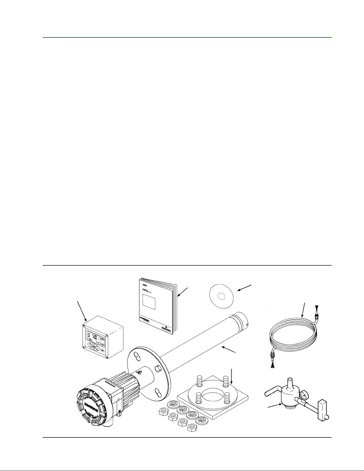
1.1 Component Checklist
A typical Rosemount Analytical O2 Combustion Flue Gas Transmitter should contain the items
shown in Figure 1-1. A complete Oxygen Analyzer system will include some or all of the equipment shown. However, this manual describes item 8 only. Record the part number, serial number,
and order number for the 6888Xi Advanced Electronics in the table located on the back cover of
this manual.
Also, use the product matrix (Table 1-1) at the end of this section to compare your order number
against your unit. The first part of the matrix defines the model. The last part defines the various
options and features. Ensure the features and options specified by your order number are on or
included with the unit.
1.2 System Overview
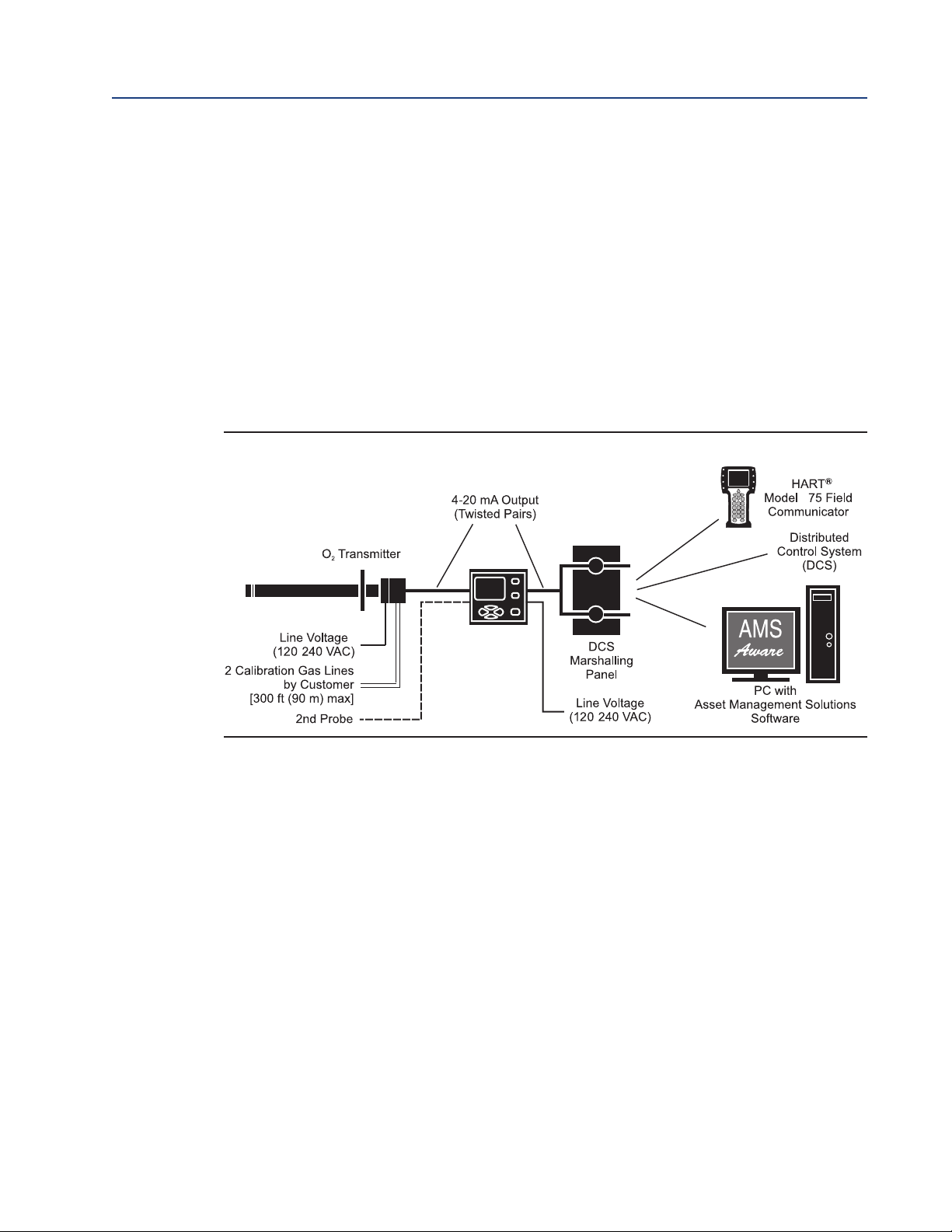
1.2.1 Power Supply-Current Loop Wiring
This Instruction Manual is designed to supply details needed to install, start up, operate, and maintain the 6888Xi Advanced Electronics. Signal conditioning electronics outputs a 4-20 mA signal
representing an O2 value. This information, plus additional details, can be accessed with the handheld HART Model 375/475 Field Communicator or Asset Management Solutions (AMS) software.
Figure 1-1. Typical System Package
Quick Start
Manual
Optional 6888Xi
Advanced Electronics
Optional Mounting
or Adapter Plate
Full Instruction
Manual DVD
Optional Traditional
Architecture Cable
6888A
Probe
Optional Reference
& Calibration Gas
Accessories
Description and Specifications 3
Page 12
ection 1: Description and Specifications 6888Xi Advanced Electronics Instruction Manual
6888A
6888Xi
Advanced
Electronics
4
/
/
S
December 2012 PN 51-6888Xi
1.2.2 System Configurations
Integral Transmitter Electronics,
HART and 6888Xi Communications
The 6888Xi Advanced Electronics, Figure 1-2, provide a local display/keypad for setting up,
calibrating, and displaying O2, and for diagnosing probe problems. The 6888Xi also offers
additional features including a "Calibration Recommended" diagnostic, fully automatic
calibration, optional flame safety interface (single probe version only), extended process
temperature capability, stoichiometer, programmable reference, and plugged diffusor. These
additional features will be discussed in other sections of this manual. The 6888Xi can be
purchased to operate a single probe, or as a dual channel unit to run two probes.
Figure 1-2. 6888A with Integral Transmitter Electronics and
Optional 6888Xi Advanced Electronics
Traditional Architecture, HART and 6888Xi Communications
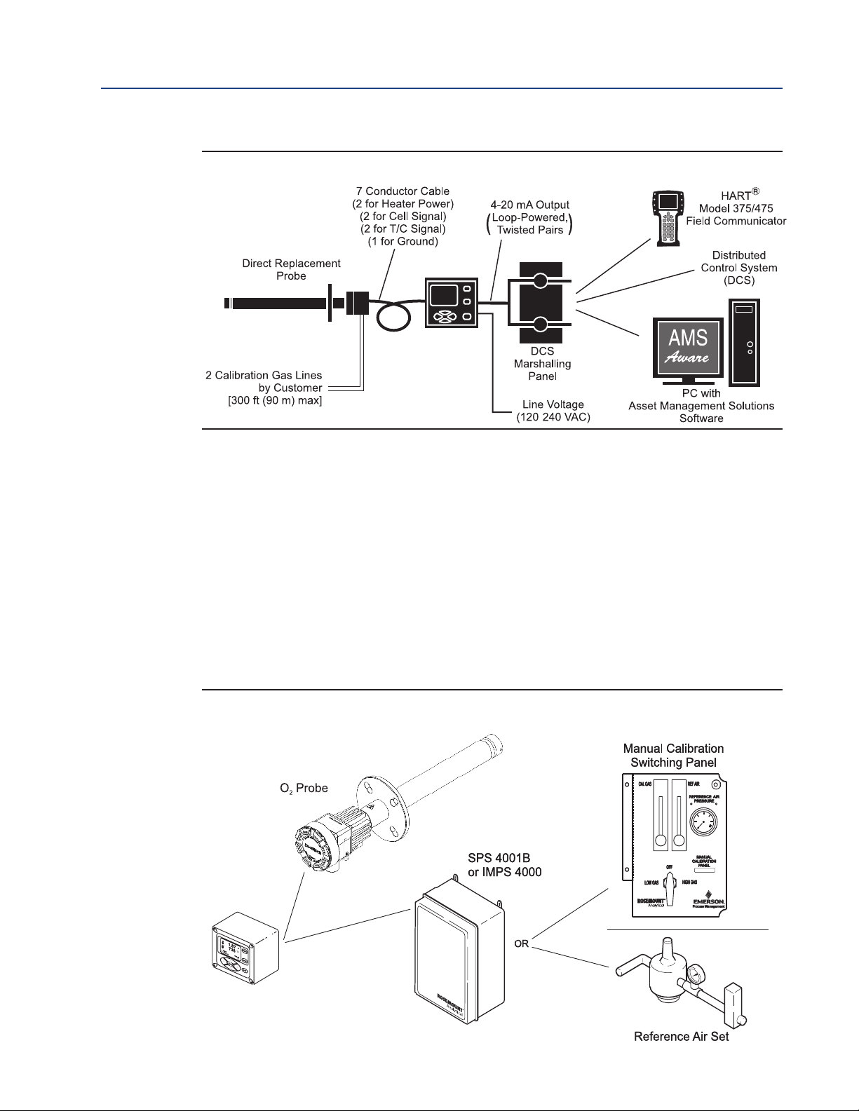
Some customers prefer not to mount electronics onto the probe, so a "traditional architecture"
version is offered. This probe sends raw millivolt signals via a 7-conductor cable to the 6888Xi
electronics, Figure 1-3, which does all heater control and signal conditioning in addition to its
display/keypad functions. The 6888Xi Advanced Electronics is offered to support direct replacement probes with 120 volt heaters.
4 Description and Specifications
Page 13
6888Xi Advanced Electronics Instruction Manual Section 1: Description and Specifications
6888Xi
Advanced
Electronics
/
PN 51-6888Xi December 2012
Figure 1-3. Direct Replacement Probe With Traditional Architecture Electronics
1.2.3 Automatic Calibration
Calibrations consist of introducing bottled gases of known value into the probe so the electronics can make automatic adjustments to the O2readings to match the bottled gas value. 0.4% O
and 8% O2(balance nitrogen) gases are recommended. Never use nitrogen or instrument air as
calibration gases.
Flowmeters (for calibration gases) and regulators and flowmeters (for reference air) are available
as loose components, mounted into an optional manual calibration switching panel, or as a fully
automatic calibration system, Figure 1-4, where calibration solenoids are switched from the
6888Xi Advanced Electronics. See IM-106-340AC, SPS 4000B Single Probe Autocalibration
Sequencer or IM-106-400IMPS, IMPS 4000 Intelligent Multiprobe Test Gas Sequencer, for additional details.
Figure 1-4. 6888A Probe with Optional 6888Xi Advanced Electronics
and Calibration Accessories
2
6888Xi
Advanced Electronics
Description and Specifications 5
Page 14

ection 1: Description and Specifications 6888Xi Advanced Electronics Instruction Manual
S
December 2012 PN 51-6888Xi
1.2.4 Communication Options
Data Communications
An operator can configure and troubleshoot the O2Probe system in one of two ways:
1. Using the 6888Xi Advanced Electronics keypad and display to access the following optional
advanced features:
• Probe configuration
• Fully automatic calibration
• Failure diagnostics
• Flame safety interface
• High temperature operation [above 700°C (1292°F) standard temperature].
• Stoichiometer feature provides the ability to indicate O
process goes into reducing conditions (0% O2).
• Programmable reference provides enhanced accuracy when measuring at or near O2level
(20.95% O2).
• Plugged diffusor diagnostics
2. Using the HART Interface. The 6888Xi’s 4-20 mA output line transmits an analog signal proportional to the oxygen level. The HART output is superimposed on the 4-20 mA output line.
This information can be accessed through the following:
• Rosemount Analytical Model 375/475 Field Communicator - The handheld communicator requires Device Description (DD) software specific to the 6888Xi. The DD software
will be supplied with many Model 375/475 units but can also be programmed into existing units at most Emerson Process Management service offices. See Section 4, Startup
and Operation, for additional information.
efficiency when the combustion
2
• Personal Computer (PC) - The use of a personal computer requires AMS software available
from Emerson Process Management.
• Delta V and Ovation Distributed Control System (DCS) with AMS-inside capability.
NOTE
The 375 Field Communicator must be upgraded to System Software 2.0 with Graphic License for
operation with the 6888Xi. The AMS software must be upgraded to AMS 8.0 or above.
Contact Emerson Process Management’s Global Service Center (GSC) at 1-800-833-8314 to upgrade
the 375 Field Communicator software to System Software 2.0 with Graphic License.
6 Description and Specifications
Page 15
6888Xi Advanced Electronics Instruction Manual
AnalyticalAnalytical
PN 51-6888Xi December 2012
Section 1: Description and Specifications
3. The 6888Xi can also transmit HART information wirelessly via a wireless THUM Adapter,
Figure 1-5. The THUM Adapter threads into the
FIGURE 1-5. Wireless THUM Adapter
with 6888Xi
6888Xi conduit port and converts the 4-20 mA
O2 signal to a wireless protocol. All other HART
information is also transmitted.
In addition to the wireless THUM Adapter, a
hard-wire connection of the 4-20 mA signal to
the DCS may be used at the same time. More
detailed information regarding the application
of the THUM Adapter is available in Product
Data Sheet 00813-0100-4075.
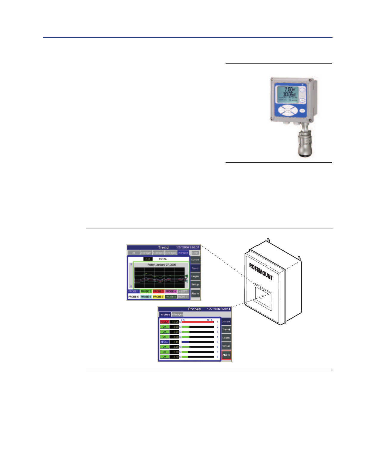
Optional OxyBalance Display and Averaging System
Receives up to eight 4-20 mA signals from individual 6888Xi units. Trends individual outputs and
calculates four programmable averages as additional 4-20 mA outputs. OxyBalance graphic displays are shown in Figure 1-5. See IM-106-4050, OxyBalance Oxygen Display and Averaging
System, for additional details.
FIGURE 1-5. OxyBalance Displays
Description and Specifications 7
Page 16
ection 1: Description and Specifications 6888Xi Advanced Electronics Instruction Manual
S
December 2012 PN 51-6888Xi
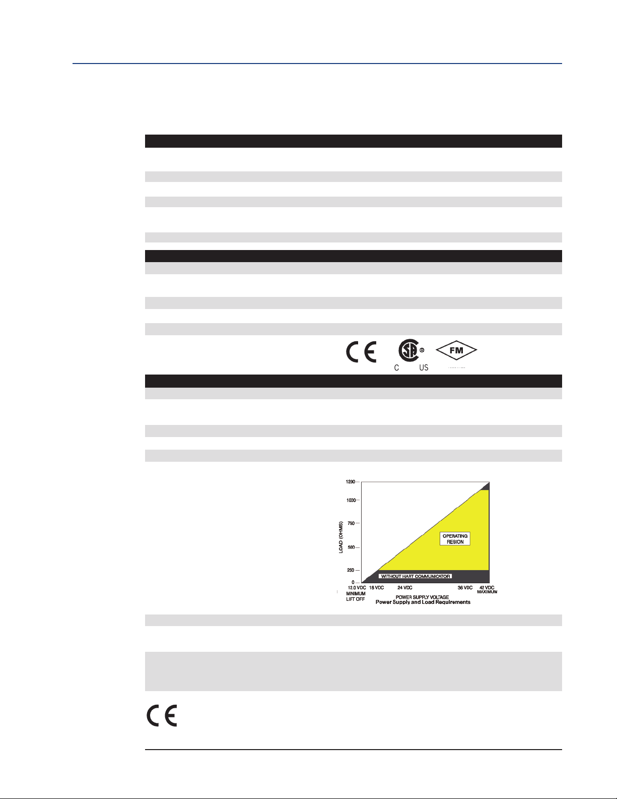
1.3 Specifications
Measurement Specifications
Net O2Range: 0 to 50% O2user scalable
Lowest Detectable Limit: 0.01% O
ignal Stability: ±0.03% O
S
Accuracy in Reducing Conditions: ±10% of reading or 0.1% O
System Response in Reducing Conditions: going from oxidizing to reducing -T90 in 120 seconds
Ambient Temperature Effect on Xi 4-20 mA Signal: less than 0.0025% O2per degree Celsius
Environmental Specifications
6888Xi Advanced Electronics: Type 4X/IP66, Polycarbonate Material
Ambient Temperature Limits: -20°C to 50°C (-4°F to 122°F)
6888Xi LCD display:
Ambient Temperature Limits -20°C to 55°C (-4°F to 131°F)
General Purpose Certifications:
-2 to 50% O
user scalable with stoichiometer
2
2
2
2
going from reducing to oxidizing -T90 in 30 seconds
-20°C to 70°C (-4°F to 158°F) as measured by electronics
Installation Specifications
Mounting: Panel, wall, or pipe.
Reference Air: 2 scfh (1L /min), clean, dry, instrument-quality air
(20.95% O
), regulated to 5 psi (34 kPa)
2
Calibration: Semi-automatic or automatic
Cal Gases: 0.4% O
and 8% O2, balance N2 recommended
2
Traditional Architecture Cable 200 ft (61 m) maxmum length
Transmitter Electrical Power: 12 - 24 VDC (loop-powered from control room or 6888Xi)
Electrical Power for 6888Xi: 120/240VAC ±10%, 50/60 Hz
Power Consumption of 6888Xi: 12 VA maximum or 1020 VA maximum with Traditional
Architecture,120V Probes
Alarm Relay Outputs: Two provided - 2 Amperes, 30 VDC, Form-C
Optional Loss of Flame Input: Internally powered input to remove heater power
actuated via dry contact output from user’s* flame scanner
Emerson Process Management has satisfied all obligations from the European legislation to harmonize the product requirements in Europe. 1All static performance characteristics are with operating
variables constant. Specifications subject to change without notice.
8 Description and Specifications
Page 17

066 Instruction Manual Section 1: Description and Specifications
1
PN 51-1066 December 2012
Table 1-1. Product Matrix, Advanced Electronics
6888Xi Advanced Electronics
Code Remote Type
1OXY Single Channel O2
2OXY Single Channel O2 with Flame Safety Interlock for Heater
3OXY Dual Channel O2
4OXY Single Channel O2, Traditional Architecture for 120V Probes
Code Mounting
00 No Hardware
01 Panel Mount Kit with Gasket
02 2" Pipe / Wall Mount Kit
Code Cable
00 No Cable
10 20' (6m) Cable
11 40' (12m) Cable
12 60' (18m) Cable
13 80' (24m) Cable
14 100' (30m) Cable
15 150' (45m) Cable
16 200' (60m) Cable
Code Stoichiometer Function
00 No
01 Single Channel
02 Dual Channel
Code Programmable Reference Function
00 None
01 Single Channel
02 Dual Channel
Code Extended Temperature Function
00 None
01 Single Channel
02 Dual Channel
Code Plugged Diffuser Diagnostic Function
00 None
01 Single Channel
02 Dual Channel
Description and Specifications 9
Page 18

ection 1: Description and Specifications 6888Xi Advanced Electronics Instruction Manual
S
December 2012 PN 51-6888Xi
Table 1-2. Product Matrix, O2Autocalibration Accessories
XS O2CAL O2 Autocalibration Accessories
Code Single Probe Sequencers Autocalibration Options
00 None
01 SPS 4001B Single Probe Sequencer, general purpose NEMA 4X, includes check valve for probe
Code Intelligent Multiprobe Sequencers (IMPS)
00 None
01 IMPS single-probe, general purpose NEMA 4X, includes check valve for probe
02 IMPS two-probe, general purpose NEMA 4X, includes check valve for probe
03 IMPS three-probe, general purpose NEMA 4X, includes check valve for probe
04 IMPS four-probe, general purpose NEMA 4X, includes check valve for probe
05 IMPS single-probe, 115V heated general purpose NEMA 4X, includes check valve for probe
06 IMPS two-probe, 115V heated general purpose NEMA 4X, includes check valve for probe
07 IMPS three-probe, 115V heated general purpose NEMA 4X, includes check valve for probe
08 IMPS four-probe, 115V heated general purpose NEMA 4X, includes check valve for probe
09 IMPS single-probe, 220V heated general purpose NEMA 4X, includes check valve for probe
10 IMPS two-probe, 220V heated general purpose NEMA 4X, includes check valve for probe
11 IMPS three-probe, 220V heated general purpose NEMA 4X, includes check valve for probe
12 IMPS four-probe, 220V heated general purpose NEMA 4X, includes check valve for probe
TABLE 1-3. Calibration Glass
Part Number Description
1A99119G01 Two disposable calibration gas bottles - 0.4% and 8% O2, balance nitrogen - 550 liters each*
1A99119G02 Two flow regulators for calibration gas bottles
1A99119G03 Bottle rack
*Calibration gas bottles cannot be shipped via airfreight.
10 Description and Specifications
Page 19

888Xi Advanced Electronics Instruction Manual Section 2: Installation
6
PN 51-6888Xi December 2012
Section 2: Installation
WARNING
Before installing this equipment read the "Safety instructions for the wiring and
installation ofthis apparatus" at the front of this Instruction Manual. Failure to
follow safety instructions could result in serious injury or death.
WARNING
Install all protective equipment covers and safety ground leads after installation. Failure to install covers and ground leads could result in serious injury or
death.
WARNING
The 6888Xi Advanced Electronics can be installed in general purpose areas
only. Do not install the 6888Xi in hazardous areas or in the vicinity of flammable liquids.
CAUTION
If external loop power is used, the power supply must be a safety extra low voltage (SELV) type.
Installation 11
Page 20
ection 2: Installation 6888Xi Advanced Electronics Instruction Manual
S
December 2012 PN 51-6888Xi
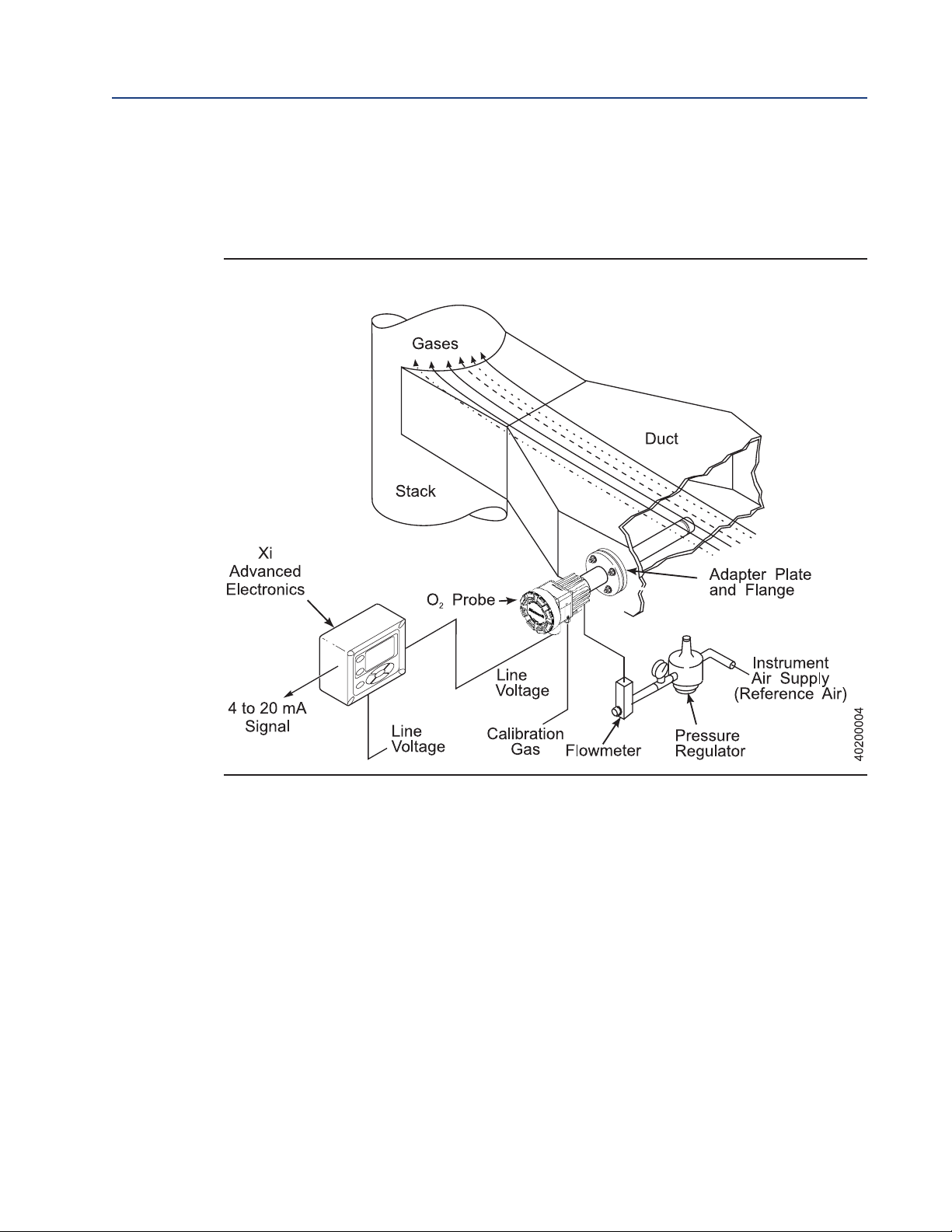
2.1 System Considerations
A typical system installation for a 6888Xi and O2 Probe is shown in Figure 2-1.
FIGURE 2-1. Typical System installation
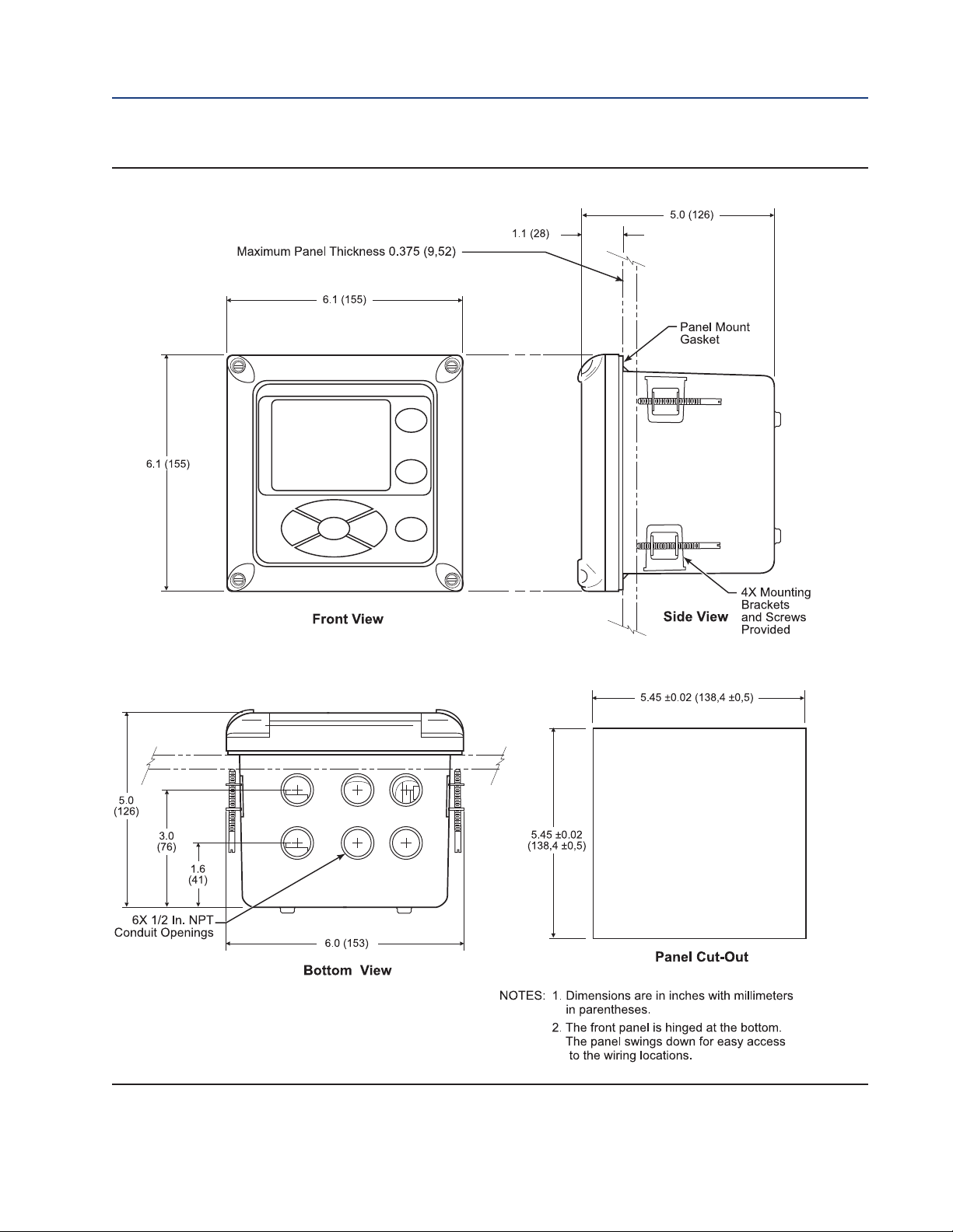
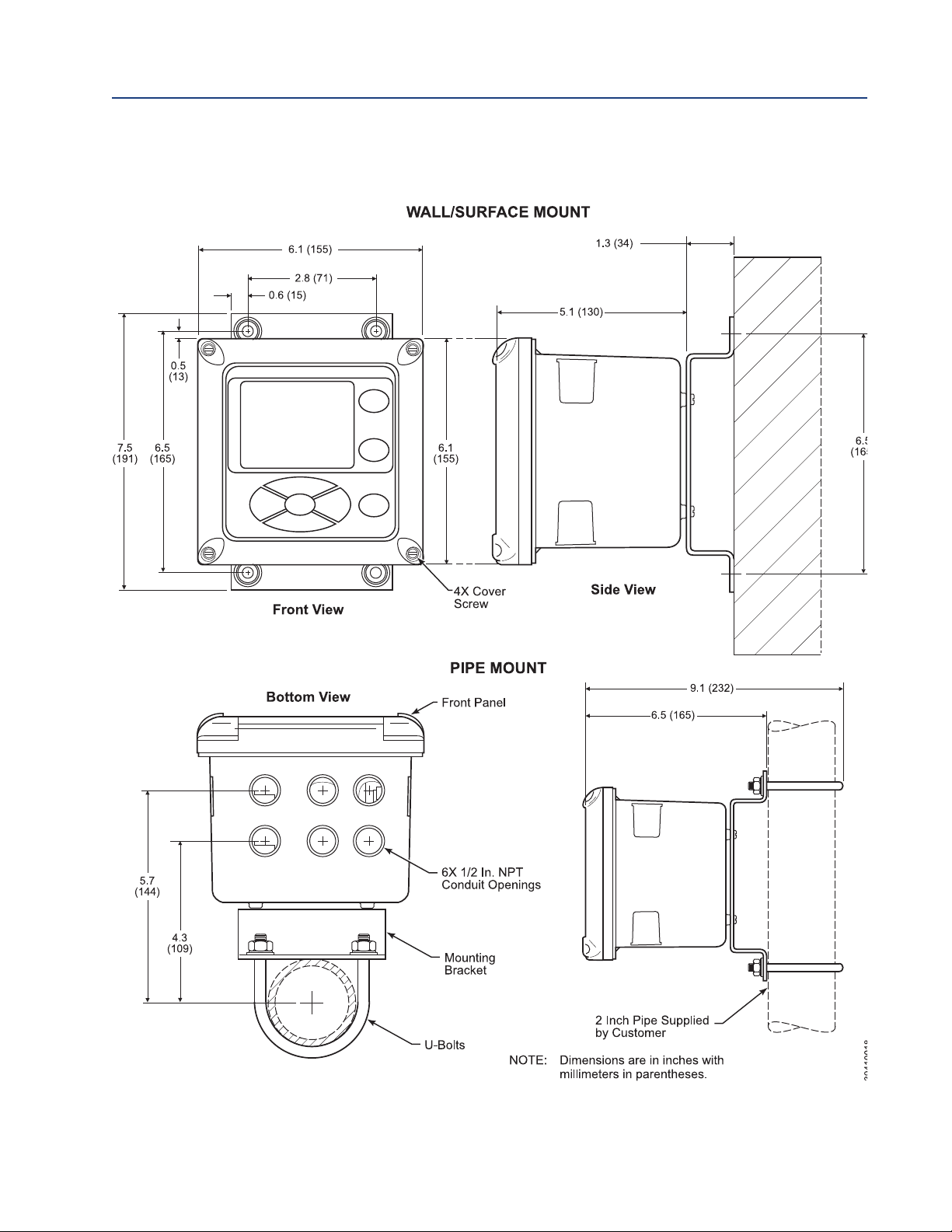
2.2 Mechanical Installation
6888Xi Advanced Electronics
The 6888Xi Advanced Electronics is available in a panel mounting, wall mounting, or pipe
mounting configuration. Refer to Figure 2-2 or Figure 2-3 for the panel, wall, or pipe mounting
details.
1. Ensure all components are available to install the 6888Xi.
2. Select a mounting location near or removed from the O2 Probe. Consider the temperature
limitations of the 6888Xi (see "Specifications") when selecting the mounting location.
3. Mount the 6888Xi at a height convenient for viewing and operating the interface.
Approximately 5 ft (1,5 m) is recommended.
4. The keypad window on the 6888Xi may have interior and exterior protective membranes.
Remove the protective membranes prior to use of the 6888Xi enclosure. Failure to remove
the protective membranes may cause the display to appear distorted. The membrane may
be difficult or impossible to remove after extended use at elevated temperatures.
12 Installation
Page 21
888Xi Advanced Electronics Instruction Manual Section 2: Installation
6
PN 51-6888Xi December 2012
FIGURE 2-2. 6888XI Advanced Electronics - Panel Mounting Details
Installation 13
Page 22
ection 2: Installation 6888Xi Advanced Electronics Instruction Manual
S
December 2012 PN 51-6888Xi
FIGURE 2-3. 6888XI Advanced Electronics - Wall/Surface and Pipe Mounting Details
14 Installation
Page 23

888Xi Advanced Electronics Instruction Manual Section 2: Installation
6
PN 51-6888Xi December 2012
2.3 Electrical Installation
6888Xi Advanced Electronics
All wiring must conform to local and national codes. Multiple wiring diagrams are shown in this
section. Always refer to the diagrams that apply to your transmitter configuration and disregard
all other wiring diagrams.
WARNING
Disconnect and lock out power before connecting the power supply.
WARNING
Install all protective covers and safety ground leads after installation. Failure to install covers and
ground leads could result in serious injury or death.
WARNING
To meet the Safety Requirements of IEC 1010 (EC requirement), and ensure safe operation of this
equipment, connection to the main electrical power supply must be made through a circuit breaker
(min 10A) which will disconnect all current-carrying conductors during a fault situation. This circuit
breaker should also include a mechanically operated isolating switch. If not, then another external
means of disconnecting the supply from the equipment should be located close by. Circuit breakers or
switches must comply with a recognized standard such as IEC 947.
NOTE
Line voltage, signal, and relay wiring must be rated for at least 105°C (221°F).
NOTE
If metal conduit is used with the 6888Xi the conduit should be reliably bonded to protective
earth. The grounding plate inside the 6888Xi is not bonded to PE and does not provide adequate
grounding.
1. Remove cover screws from the front cover of the 6888Xi. Swing down the front cover of the
interface box.
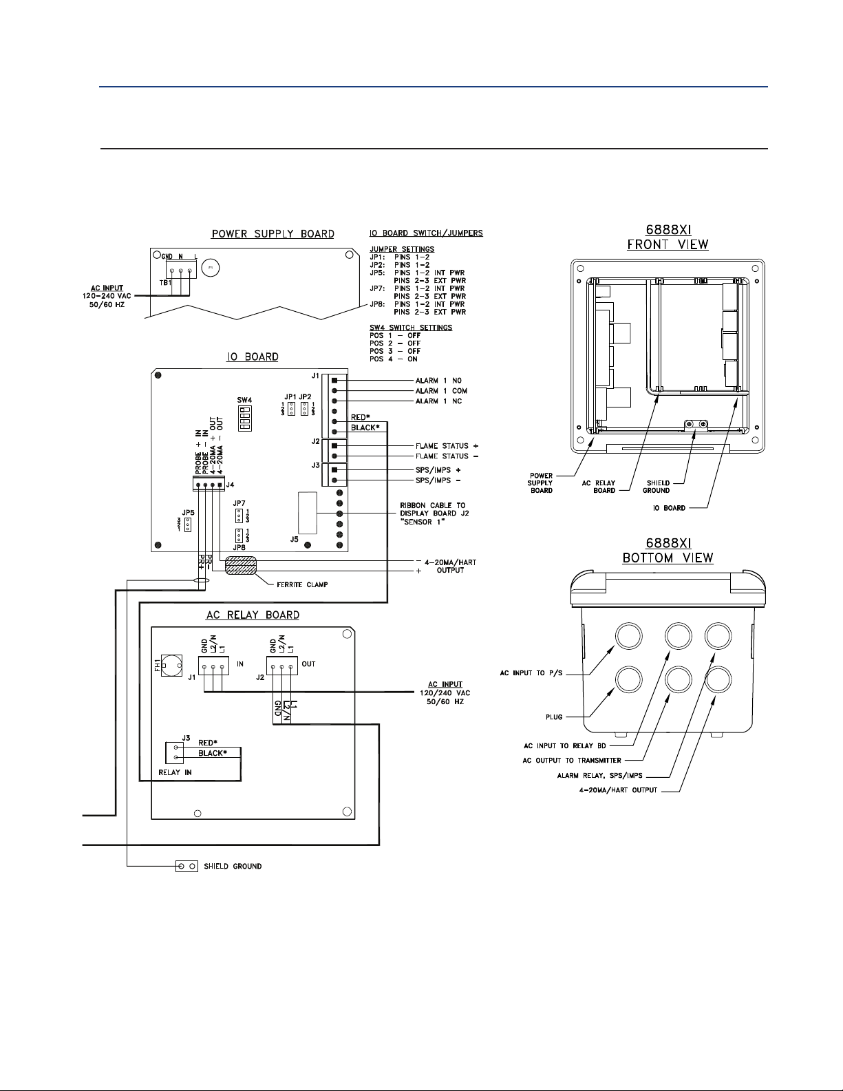
2. Pull out the I/O board on the right-hand side of the card rack inside the 6888Xi. If your system is configured to operate two transmitter probes there are two I/O interface boards.
3. See Figures 2-5, 2-6 and 2-7. Connect the 4-20 mA signal wires at J4 of the I/O board. Attach
the supplied ferrite clamp over the 4-20 mA OUT wires that extend past the shield.
NOTE
Installation of the ferrite clamp over the 4-20 mA OUT wires is required for compliance with the
European EMC Directive.
4. Terminate the shield of the 4-20 mA signal wires at the designated ground terminal of the
6888Xi. Do not allow bare shield wires to contact the circuit boards. Insulate the shield wires
prior to termination.
5. Connect the signal wires from the SPS or IMPS (if used) to the applicable terminals of J3.
Refer to the SPS or IMPS instruction manual for wiring details.
Installation 15
Page 24
ection 2: Installation 6888Xi Advanced Electronics Instruction Manual
S
December 2012 PN 51-6888Xi
6. Connect the customer’s alarm indicator devices to the alarm indicator relay terminals.
. Reinstall the I/O board in the card rack of the 6888Xi.
7
8. If your system is configured for two channel operation, repeat steps 2 through 7 to connect
the other signal wires.
9. Remove the connector from the power supply board located on the left-hand side of the
card rack inside the 6888Xi.
10. Connect the line, or L1 wire to the L1 terminal and the neutral, or L2 wire, to the N terminal.
11. Reinstall the power supply connector in the power supply board.
Flame Safety Interlock
A flame safety interlock by Emerson Process Management is available for heater power disconnect whenever there is a loss of the process flame or a heater runaway condition (heater overtemperature) in the O2 Probe. This input is internally powered by the 6888Xi and is actuated via
a dry contact output from the user’s flame scanner. A closed contact indicates a flame is present. An open contact indicates a loss of flame.
1. Connect the signal wires from the burner management system flame status output to the
flame status input terminals of J2. The flame status sensing device is supplied by the customer. Refer to the applicable OEM documents for signal wiring details.
2. Remove the J1 and J2 connectors from the AC relay board.
3. Connect the AC line input to the J1 connector.
4. Connect the AC power to the 6888A probe to the J2 connector.
5. Reinstall connector J1 and J2 to the AC relay board.
Traditional Architecture Cable Connections
A traditional architecture configuration is used to provide for remote location of the transmitter
electronics. All electronics are housed inside the 6888Xi. A multi-conductor power/signal cable
connects between the probe and the 6888Xi. Use the following procedure to connect the traditional architecture probe to the 6888Xi.
NOTE
The Traditional Architecture cable is provided at the specified length and is ready for installation. The cable
glands must be properly terminated to maintain EMC/EMI noise protection.
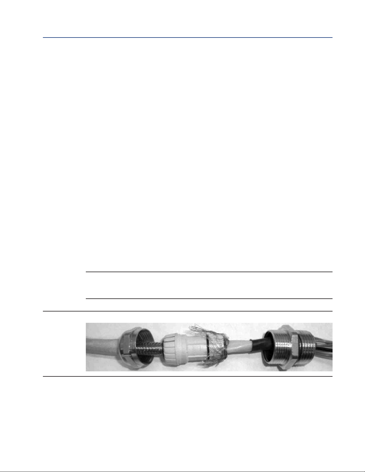
FIGURE 2-4. Traditional Architecture Cable Gland Assembly
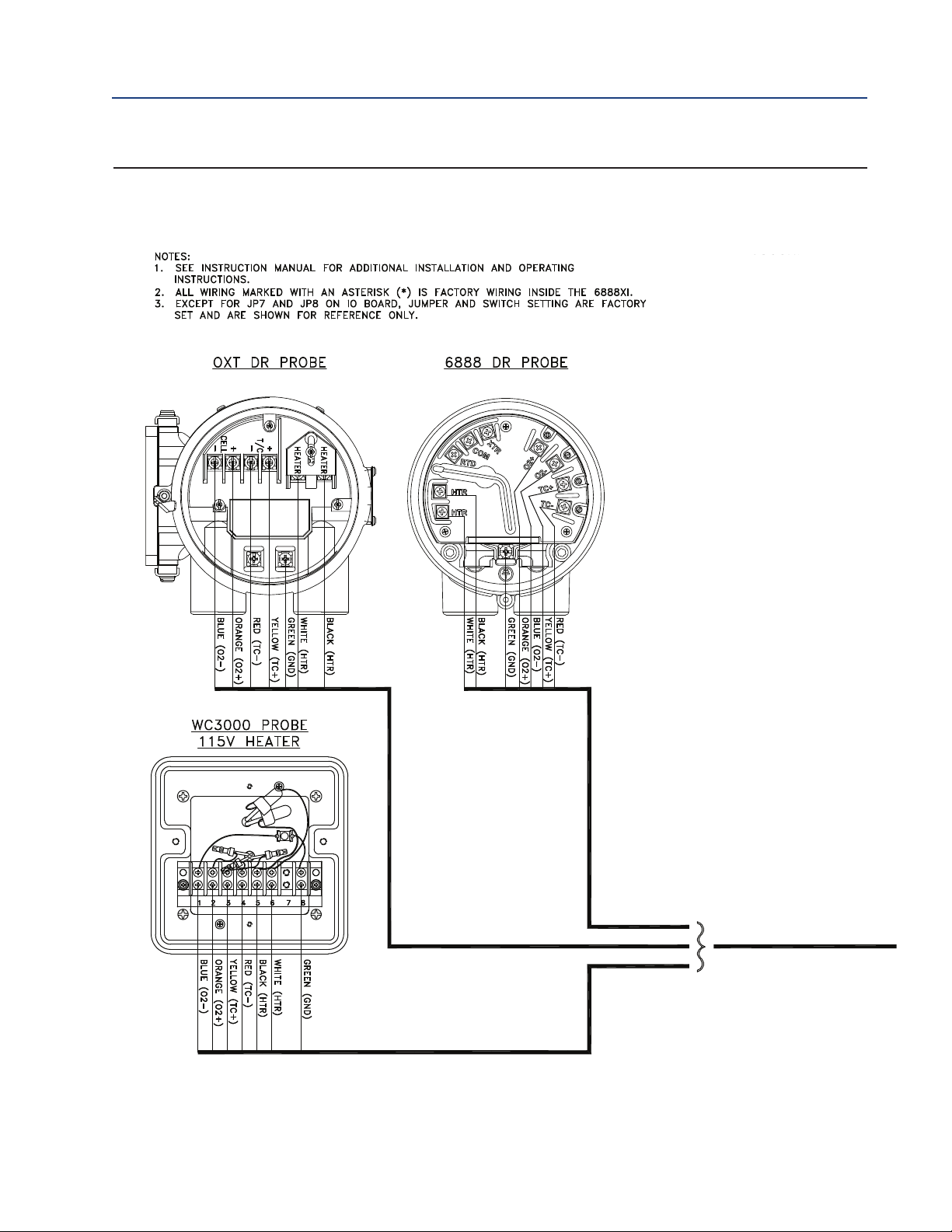
1. Run the 7-conductor cable between the traditional architecture probe and the installation
site for 6888Xi.
Use new cable conduit or trough as needed.
2. Install the cable and lead wires to the probe per manufacturer’s instructions.
3. Install the cable at the probe housing and at the 6888Xi enclosure according to the follow-
ing procedure:
a. Unscrew locking nut from gland assembly, Figure 2-4, and slide locking nut back along
16 Installation
Page 25

888Xi Advanced Electronics Instruction Manual Section 2: Installation
6
PN 51-6888Xi December 2012
cable.
b. Pull the gland body away from the plastic insert. Use care not to damage the cable
shield braid.
c. Insert the cable wires into the proper entry port in either the probe housing or the
6888Xi enclosure.
d. At the probe housing, apply Teflon tape or similar sealing compound to the tapered
pipe threads. Thread the gland body into the probe housing until properly seated.
e. At the 6888Xi enclosure, insert the gland body into the left front cable port from the
inside of the enclosure. Use the rubber O-ring provided to seal the cable port.
f. Ensure the cable shield braid is evenly formed over the gray insert. When properly
formed, the braid should be evenly spaced around the circumference of the insert and
not extend beyond the narrow diameter portion.
g. Carefully press the gray insert into the gland body. The grooves on the insert should
align with similar grooves inside the gland body. Press the insert in until it bottoms out
in the gland body.
h. Slide the locking nut up and thread it onto the gland body. Tighten the locking nut so
the rubber grommet inside the plastic insert compresses against the cable wall to provide an environmental seal.
4. At the 6888Xi, connect the cable leads to the connectors on the transmitter I/O board as
indicated in Figure 2-7.
Installation 17
Page 26
ection 2: Installation 6888Xi Advanced Electronics Instruction Manual
S
December 2012 PN 51-6888Xi
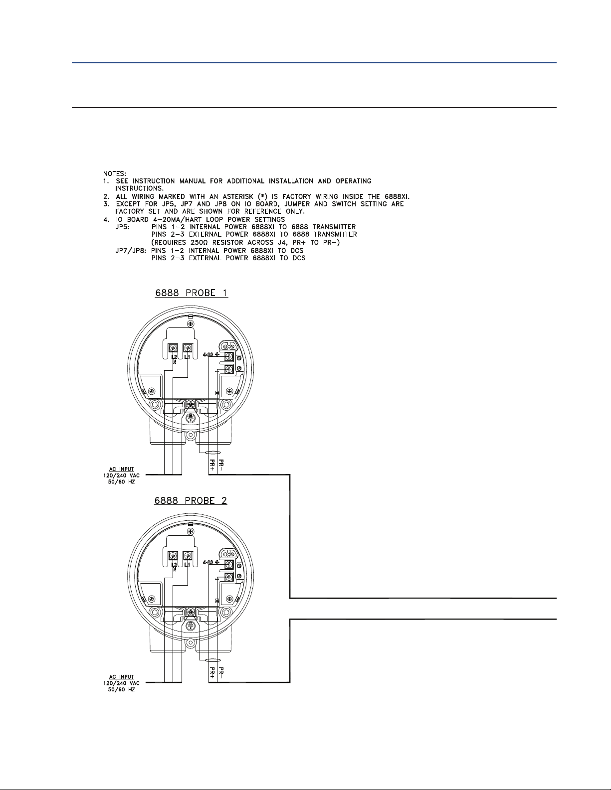
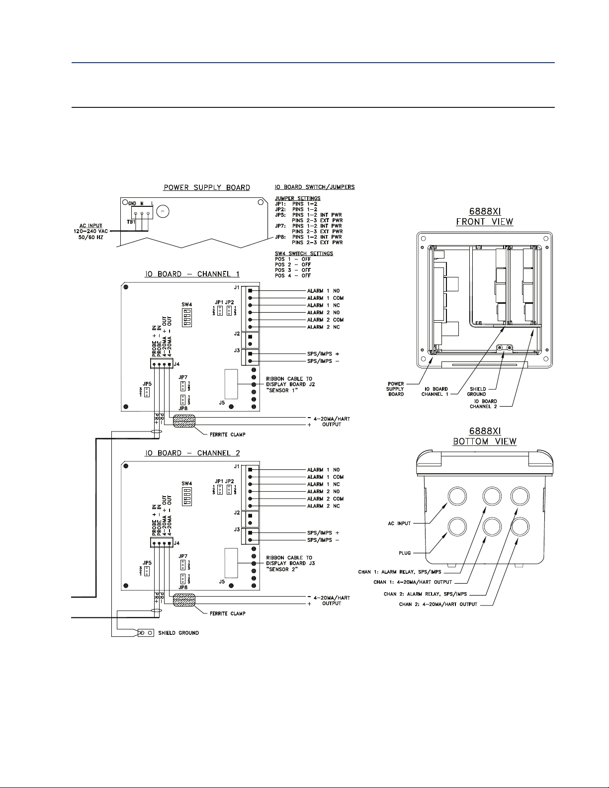
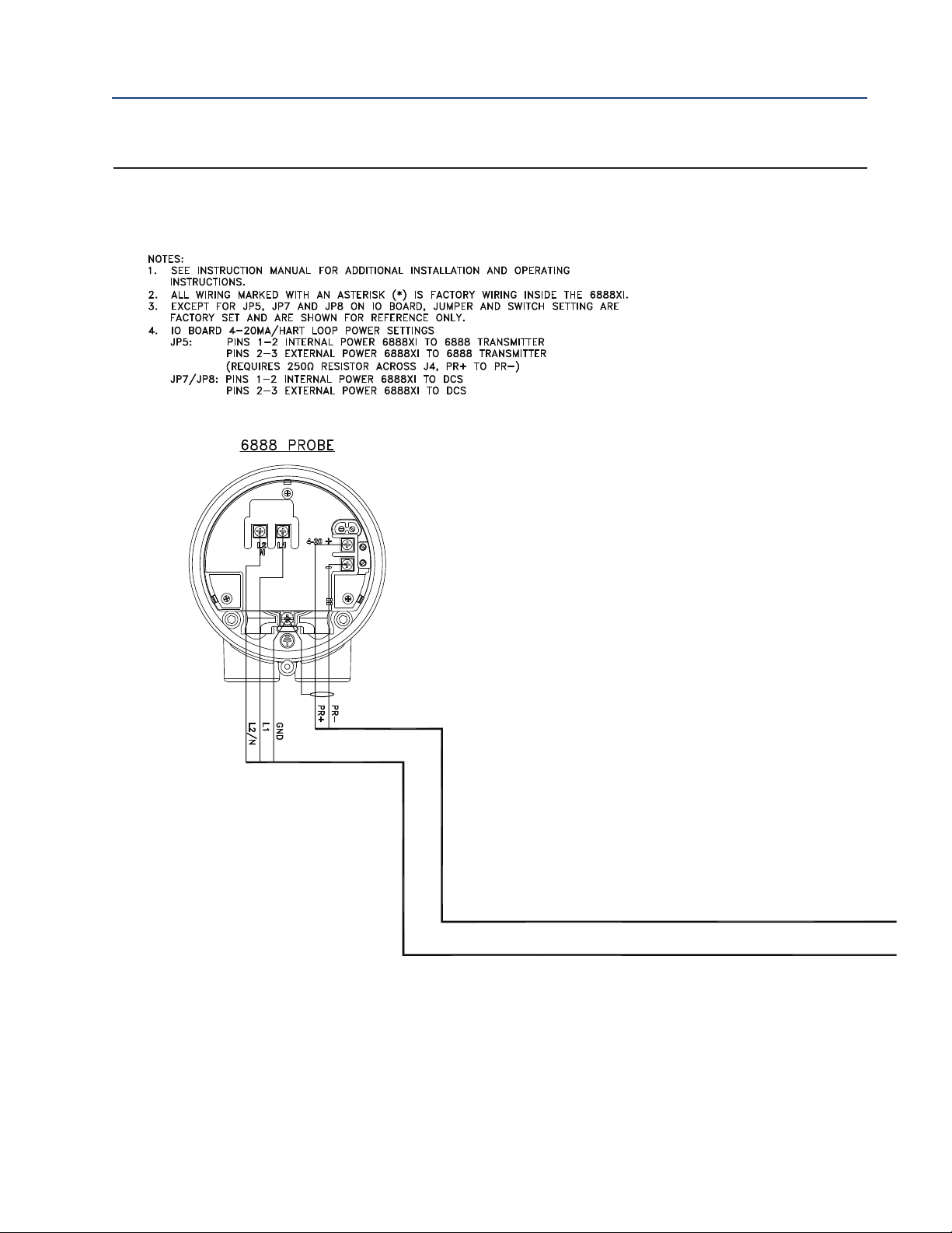
FIGURE 2-5. Single/Dual Channel Wiring Diagram
18 Installation
Page 27
888Xi Advanced Electronics Instruction Manual Section 2: Installation
6
PN 51-6888Xi December 2012
FIGURE 2-5 cont. Single/Dual Channel Wiring Diagram
Installation 19
Page 28
ection 2: Installation 6888Xi Advanced Electronics Instruction Manual
S
December 2012 PN 51-6888Xi
IGURE 2-6. Single Channel with Flame Safety Wiring Diagram
F
20 Installation
Page 29
888Xi Advanced Electronics Instruction Manual Section 2: Installation
6
PN 51-6888Xi December 2012
IGURE 2-6 cont. Single Channel with Flame Safety Wiring Diagram
F
Installation 21
Page 30
ection 2: Installation 6888Xi Advanced Electronics Instruction Manual
S
December 2012 PN 51-6888Xi
IGURE 2-7. Traditional Architecture Wiring Diagram
F
22 Installation
Page 31

888Xi Advanced Electronics Instruction Manual Section 2: Installation
6
PN 51-6888Xi December 2012
IGURE 2-7 cont. Traditional Architecture Wiring Diagram
F
Installation 23
Page 32

ection 2: Installation 6888Xi Advanced Electronics Instruction Manual
S
December 2012 PN 51-6888Xi
24 Installation
Page 33

888Xi Advanced Electronics Instruction Manual Section 3: Configuration, Startup and Operation
6
PN 51-6888Xi December 2012
Section 3: Configuration, Startup
and Operation
WARNING
nstall all protective equipment covers and safety ground leads before equipment startup. Failure to
I
install covers and ground leads could result in serious injury or death.
CAUTION
If external loop power is used, the power supply must be a safety extra low voltage (SELV) type.
3.1 Overview
Interface to the 6888Xi for setup, calibration and diagnostics can be via a 375/475 Field
Communicator or Asset Management System. Setup, calibration and diagnostic operations will
differ depending on the selected interface for communications with the transmitter.
3.2 Startup
NOTE
The 6888Xi offers optional advanced features such as extended temperature capability, autocalibration via an SPS or IMPS, a stoichiometer feature for indicating the level of oxygen deficiency in
reducing conditions, programmable reference to enhance accuracy at near ambient levels of O
plugged diffusor diagnostics to help detect when the diffusor requires maintenance.
2
and
Configuration, Startup and Operation 25
Page 34

ection 3: Configuration, Startup and Operation 6888Xi Advanced Electronics Instruction Manual
6888Xi
6888Xi
6888Xi
6888Xi
S
December 2012 PN 51-6888Xi
3.2.1 Configuration
Refer to Figure 3-1 for the configuration of jumpers JP1 through JP8. The jumper configuration for
your I/O board depends on the system design and system components used in your installation.
The setting of switch SW4 and the configuration of jumpers JP1 through JP8 must be verified on
the I/O board in the 6888Xi. Refer to figures 2-5, 2-6 and 2-7 in Section 2 for additional details.
FIGURE 3-1. I/O Board Jumper Configuration
3.2.2 Operation
The following procedures describe operations using the 6888Xi to set up and calibrate the system. Additional operating instructions are included in the SPS 4001B or IMPS 4000 instruction
manual, if applicable to your system.
3.2.3 Startup Display
The O2Probe will take approximately 45 minutes to warm up to the 736°C heater setpoint. The
4-20 mA signal will remain at a default value of 3.5 mA through this warm-up period. Once warm,
the probe will be reading oxygen and the 4-20 mA signal display will be the 0 to 10% O2value.
26 Configuration, Startup and Operation
Page 35

888Xi Advanced Electronics Instruction Manual Section 3: Configuration, Startup and Operation
6
PN 51-6888Xi December 2012
IGURE 3-2. 6888XI Display (Typical)
F
3.2.4 Error Conditions
If there is an error condition at startup, an alarm message will be displayed. Refer to Section 4:
Troubleshooting, to determine the cause of the error. Clear the error and cycle power. The O
and temperature display should return less the alarm message.
3.2.5 Keypad
The 6888Xi can be used to change the software and alarm settings, to adjust the high and low
gas settings, and to initiate the calibration sequence. Refer to the following control descriptions.
Use the control keys on the front panel of the 6888Xi, Figure 3-2, to navigate the 6888Xi menu,
Figure 3-3.
MENU toggles between three Main menu options: System, Probe1, and\ Probe2 (if available).
The top level of the selected main menu is displayed.
DIAG toggles between the Alarms list of the three main menus. All faults and warnings related
to the selected main menu device are displayed.
ENTER saves newly entered data and returns you to previous menu level.
EXIT returns you to the previous menu level without saving newly entered data. When navigat-
ing the menu tree, pressing EXIT returns you to the Main menu.
UP/DOWN keys scroll up and down through menu items. During data entry the Up/Down keys
increment and decrement the data values.
2
LEFT arrow key returns you to the previous menu level. During data entry, the left arrow key
moves the cursor one digit to the left.
Configuration, Startup and Operation 27
Page 36

!"!#$% &&&&& '()*+,!#(-! &&&&& )./012)34567
!
#)#8 !
&
&&&&!"!#$%
&
&&&&-,%292':7.;<<1.=
-
,%2>2':7.;<<1.=
+?2%16;5@2A4:3
A)-2 %1 6;5 @2 A4: 3
(
,B292#@C12%:764=.D
(,B2>2#@C12%:764=.D
(,B292B4E2-D1.F7G6
(
,B2>2B4E2-D1.F7G6
)-H+,IJ$'*$2)J)K%! &&&&& ).F2(,B92B4E2-F7G6
)
.F2(,B>2B4E2-F7G62L+;=129M
%)(+#$+)+-$ &&&&& K$?(!(,+! &&&&& ?157 :;<
BG:3E2+G6
K$!$# &&&&& K17=45=2 -;G<=
K171=2K17=45=2-;G<=
K
171=2!@7=162N45467
K
$!$#2O( &&&&& K171=2O(
$<4P312A4.=;5@ K171=28(2B;45E
-
,+A(*8K$28(B &&&&& #4Q
+G62(R,2B;45E
%$+8 &&&&& (R,2B,)K'29 &&&&& N5;P12-;G<=
'
102#@C129
(R,2B,)K'2>2L+;=129M &&&&& N5;P12-;G<=
'102#@C129
%)(+2'(!NJ)" &&&&& ,+$R#I,&NK,B$2A,K%)# &&&&& J(+$29 &&&&& -1<=15
L+;=12>M
J(+$2> &&&&& -1<=15
J(+$2S &&&&& J1T
K:QD=
J(+$2U &&&&& J1T
K:QD=
K1015=2#:61
J4<QG4Q1
-;<=547=
K171=2-; <=547=
A347D2)3456
!$-8K(#" &&&&& N477V;5E
L-;</<G1EM $<4P312N477V;5E
ection 3: Configuration, Startup and Operation 6888Xi Advanced Electronics Instruction Manual
S
December 2012 PN 51-6888Xi
igure 3-3. 6888Xi Menu (Sheet 1 of 6)
F
28 Configuration, Startup and Operation
Page 37

888Xi Advanced Electronics Instruction Manual Section 3: Configuration, Startup and Operation
!"!#$% &&&&& '()*+*,-./
(0123456$7308 &&&&& 390780:6;7< &&&&& 6$=3!301! &&&&& =->?@)*
(A-BC?,D
3087!1
2$:#56$! &&&&& !E)@BA@)D-E->
F>)G76-H->-*B-
$IE-*.-.7#-DJ
;@K,?->7LM>*@@*G
2MBE)> N7%). -
6-?-E7O3
6-?-E739 078)M>.
390780:6;7P7'1)E-7</ &&&&& 6$=3!301! &&&&& =->?@)*
(A-BC?,D
3087!1
2$:#56$! &&&&& !E)@BA@)D-E->
F>)G76-H->-*B-
$
IE-*.-.7#-DJ
;@K,?->7LM>*@@*G
2MBE)> N7%). -
6
-?-E7O3
6-?-E739 078)M>.
1RWHVisible if the device is configured for 2 I/O boards.
1RWHLabel differently based on one or two I/O boards.
6
PN 51-6888Xi December 2012
igure 3-3. 6888Xi Menu (Sheet 2 of 6)
F
Configuration, Startup and Operation 29
Page 38

!"#$%$&'"#($% ))))) &'"*(++ ))))) &'"*(++$,-'!-#.(+ ))))) "/
0
1,-'!-#.(+ "/$2345
!"#$%$&'"#($/ *366$2345
"/$*366
2
(7&('-28'(+ ))))) "/$2345
*
9*$2345
#
0:1;$2345
"
&$70;3
'-<$,-.8(+ ))))) "/$*366
*366$!45
2=*$,06 >
?3:>31
85;:>3$*366$!45
-@-."A$"82&82 ))))) "/$-"
"
/$-"B
"
/$.',
"/$8',
7
-C!787+ ))))) 2(7&('-28'( ))))) "/$2345$7:D
"/$2345$7:D$2E43
*9*$7:D
*
9*$7:D$2E43
#0:1;$7:D
#0:1;$7:D$2E43
,
".2-A( ))))) ?3:>31$7:D
?3:>31$7:D$2E43
*366$7:D
*366$7:D$2E43
'-7&$'-2( ))))) ?3:>31$7:D
?3:>31$7:D$2E43
?(-2(' ))))) FG>H$*HI63
"/$2345$+&
"/$2345
?3:>31$':45$':>3
F!-A@"+2!*+ ))))) -IJK3$-6:14L
+2-28+ ))))) *8''(@2 ))))) F(,!*( ))))) &,$"G>$.E4E>
@&,$"G>$.E4E>
-"$+:>G1:>3;
-"$MED3;
7013$+>:>GL
*06;$+>:1>
*NO$*P:QO3;
F3K$M:E6G13
M-!.(F )) )) ) @, $7 340 1H $M: E6
#0:1;$2345$?EOP
M:I>01 H$70; 3
?3:>31$':45$':>3
7-!@2(@-@*($% ))))) "/$+3QL01$"53Q
"/$2=*$"53Q
"/$2345$.0R
"/$2345$?EOP
"/$2=*$+P01>3;
"/$2=*$'3K31L3;
?3:>31$M:E6G13
S*0QJQG3;T S*0QJQG3;T S*0QJQG3;T S*0QJQG3;T #G1Q31$M6:430G>
ection 3: Configuration, Startup and Operation 6888Xi Advanced Electronics Instruction Manual
S
December 2012 PN 51-6888Xi
igure 3-3. 6888Xi Menu (Sheet 3 of 6)
F
30 Configuration, Startup and Operation
Page 39

888Xi Advanced Electronics Instruction Manual Section 3: Configuration, Startup and Operation
!"#$%$&'"#($% ))))) *+,-.-/012 *+,-.-/012 *+,-.-/012 *+,-.-/012
,3
!
"#$%$&'"#($4 56!78(767+($4 ))))) 9:;3$<=>?,--0?;
+@A$'0?,::0-101
+@A$B@=A01
+0AA$!:C$D=EF
&3,G0$5=>:@;?F
6
<H!I"'J ))))) +@A$+F@-E01
D
0@;03$H,A;$K,L
&3,G0$+F@-E01
K,L$"4
<
=M/>03$N@3-=-E
&'(H!"OI ))))) &30P=,/>$6A@3:>
6?Q$6A@3:$8=:0
6+R7"NK(<S($6K6'5I ))))) 6?Q$+@A=G3@.,-
6
?Q$+@A$B@=A01
6+R$&'"#($+D67S(< )) ))) S0;$T3,:$&3,G0
I0-1$;,$&3,G0
6+R$<!BB$N6'7!7S
56!78(767+( ))))) '(H!I!"7I ))))) D6'8 ))))) <0P=?0$'0P
8
'67I5!88(' ))))) H03>=,-
!U"$#"6'< ))))) H03>=,-
676K"S$"O8&O8 ))))) 83=:$:6$"/;C/;
"&('68!7S$I868OI ))))) B@?;,3V$5,10
BA@:0$I;@;/>
6/;,$+@A$<0P=?0
'0A@V$%$<0P=?0
'0A@V$4$<0P=?0
6"$<0P=?0
!U"$I868(I ))))) !U"$I868(I$% ))))) S@>$%$I,A0-,=1
S@>$4$I,A0-,=1
!U"$I868(I$4 ))))) BA@:0$I;@;/>$!-
B@?;,3 V$5,1 0
'0A@V$%$"/;
'0A@V$4$"/;
I&IU!5&I$!-
I&IU!5&I$"/;
(($I868OI ))))) 9:;3$(($H@A/0$
!"#$(($H@A/0
'(I(8 ))))) 9:;3$'0>;@3;
!"#$'0>;@3;
'0>0;$'0>;@3;$+,/-;
*+,-.-/012 '0>0;$<0 P=?0
6
PN 51-6888Xi December 2012
igure 3-3. 6888Xi Menu (Sheet 4 of 6)
F
Configuration, Startup and Operation 31
Page 40

ection 3: Configuration, Startup and Operation 6888Xi Advanced Electronics Instruction Manual
!"#$%$&'"#($% ))))) *+,-.-/012
,3
!
"#$%$&'"#($4 #56!+$6(78& ))))) !9(:7!;!+57!": ))))) 7<=603><?$:/@A03
90B>C0$!9
+
"DD8:!+57!":
)
))))&,??$51130EE
F
@G3$51130EE
H5'! 5#I ($D 5&& !:J ))) )) &H6H7
H
KH
9(75!I(9$6(78& ))))) 6(:6"' ))))) 7LM$;>?G03
I
,N$"4$5?@$6&
"4$+0??$'0O$$*:,G0$42
P>=Q$70@R$5?@$6&$*:,G0$S2
P0<G03$6&$*:,G0$S2
P
0<G03$I<GCQ$"T$*:,G0$S2
;
(578'(6 ))))) 6G,>CQ>,@0G03
&3,=$'0O030-C0
(UG0-101$70@R
9
>T/E03$V<3->-=
5:5I"J$"87&87 ))))) "4$I'H
"4$8'H
5"$'<-=0
5?<3@$I0B0?
'(I5W ))))) '(I5W$% ))))) 8->G$5?<3@
I,N$"4
+<?$'0C,@@0-101
!-$+<?>A3<.,-
'(I5W$4 ))))) 8->G$5?<3@
I,N$"4
+<?$'0C,@@0-101
!-$+<?>A3<.,-
P0<G03$'0?<X
+5I!#'57!": ))))) 5"$73<CY
7,? $ +Q 0 CY
+<?$'0C,@@0-1
+<?$5CY-,N?01=0
+<?$J<E$%
+<?$J<E$4
J<E$7>@0
&/3=0$7>@0
9!;;86('$*:,G0$K2 ))))) &?/==01$9>T/E03
5/G,$51B<-C0$+<?
587"$+5I!# '57!": ))))) (-<A?0$5/G,$+<?
6G<3G$,-$+<?$'0C
+<?$!-G03B<?
:0UG$+<?$7>@0
'(6"8'+( ))))) 5-<?,=$"/GR/G
5/G,$+<?
'0?<X$%
'0?<X$4
*+,-.-/012
S
December 2012 PN 51-6888Xi
igure 3-3. 6888Xi Menu (Sheet 5 of 6)
F
32 Configuration, Startup and Operation
Page 41

888Xi Advanced Electronics Instruction Manual Section 3: Configuration, Startup and Operation
!"#$%$&'"#($% ))))) *+,-.-/012
,3
!"#$%$&'"#($4 +56!#'57!"8 ))))) "4$+9:;<39.,-
5<,3=$+9:;<39.,-
+9:$>=9=0
+56$+"8>7587> ))))) +?''(87$+56 ))))) >:,@0
+,-A=9-=
!B@019-C0
7;B0
'0A0=$+9 :
+D9-E0$+9:
+
9:$6,EA
F5! 6(G $+ 56 ) ))) ) # 91 $>:,@ 0
#91$+,-A=9-=
+56$'(>?67 ))))) +9:$'0A/:=
G
0:=9$!B@
G!FF?>(' ))))) G!FF$G!5H8">7!+> ))))) &3,C0AA
"4>
=0@
>=0@$7;B0
G;9E$>=9=0
!-;=$'0A@
&3,C0AA$'0A@
'=-$&3,C0AA
"4$'9=0$+D9-E0
G;I$7JK
&/3E0$7;B0$L
G;I$M93-
&'(>>?'(>$*8,=0$%2 ))))) #,N:0$&30AA/30$%
#,N:0$&30AA/30$4
+0::$&30AA/30$%
+0::$&30AA/30$4
1RWH9LVLEOHLIWKHGHYLFHLVFRQILJXUHGIRU+636$XWRFDO
1RWHVisible if the Programmable Reference software feature is enabled.
1RWHVisible if the Extended Temperature software feature is enabled.
1RWHVisible if the Diffuser Warning software feature is enabled.
1RWHVisible if the Factory Mode switch is on.
6
PN 51-6888Xi December 2012
igure 3-3. 6888Xi Menu (Sheet 6 of 6)
F
Configuration, Startup and Operation 33
Page 42

ection 3: Configuration, Startup and Operation 6888Xi Advanced Electronics Instruction Manual
S
December 2012 PN 51-6888Xi
RIGHT arrow key advances you to the next menu level and, when a menu
item is highlighted, selects the item from a list of menu options. During data
entry, the right arrow key moves the cursor one digit to the right.
3.2.6 Password Protection
The main display and diagnostic screens of the 6888Xi can be viewed at any time, but further
access and unauthorized configuration changes can be prevented by enabling a password protection feature. However, the 6888Xi is shipped with password protection disabled.
Password protection can be enabled by selecting: System Main Menu > Configure UIB > Security
> Enable Password (see the 6888Xi Menu, Figure 3-3).
The factory default upon enabling the password protection is 0000, but the password can consist of any 4 numeric characters.
If the user forgets the password, call Rosemount Analytical technical support at 800-433-6076
to gain access to a master password.
A "Lock" icon will be displayed at the top right corner of the main display when password protection is in effect.
The password protection will relock itself after a certain number of seconds with no button
pushes (defined as "revert time" in the same "LCD setup" menu).
The 6888Xi has a "Reset" function that reestablishes all factory default conditions, including the
password protection feature, i.e. the password protection will fall back to a disabled condition
after a reset.
3.3 Optional Advanced Features
Advanced features are typically ordered factory programmed. However, these advanced features are also available for field retrofit.
A 6888Xi is shipped from the factory with the optional enhanced software features enabled
based on the model configuration.
WARNING
The I/O Board is shipped from the factory without any of the enhanced software features activated.
These features must be activated once the new board has been installed and before the Remote
Interface is put into service.
WARNING
If the existing I/O Board has been operated with the Stoichiometric enhanced software feature, this
feature must be activated in the new board before the Remote Interface is put back into service.
Failure to do so will cause a false analog output signal to the DCS.
34 Configuration, Startup and Operation
Page 43

888Xi Advanced Electronics Instruction Manual Section 3: Configuration, Startup and Operation
6
PN 51-6888Xi December 2012
NOTE
For enhanced software feature option upgrades or to enable the feature to duplicate the existing
configuration, contact Emerson Process Management at 1-800-433-6076. Reference the following:
6A00269G01 Enhanced Software Option Upgrade, Stoichiometric Function
6A00269G02 Enhanced Software Option Upgrade, Programmable Reference Function
6A00269G03 Enhanced Software Option Upgrade, Extended Temperature Function
6A00269G04 Enhanced Software Option Upgrade, Diffuser Warning Function
3.3.1 Extended Temperature
The Oxygen Analyzer employs a heater and thermocouple to maintain a temperature normal set
point at 736°C (1357°F). Temperature control is maintained within ±1°C to process temperatures
of about 705°C (1300°F). This is satisfactory for most applications, but excursions to higher temperatures can occur in some processes.
The extended temperature function allows the heater to be turned off and the process temperature used to heat the sensing cell. The function also provided for configuring the heater to operate at either 736°C (1357°F) or 550°C (1022°F). A lower temperature may be desirable by turning off the heater at a lower temperature to reduce the instance of an ignition source in the
process. Furthermore, the user has the ability to choose whether or not the heater will turn back
on if the process temperature falls below the set point. Again, this reduces the instance of an
ignition source in the process if a flameout condition should occur.
When the extended temperature function is disabled the heater normal set point is at 736°C. An
alarm will occur if the heater falls below 726°C or rises above 750°C. Either of these alarms will
also force the analog output signal to a critical alarm level of either 3.5 mA or 21.5 mA as configured. When the extended temperature function is enabled, an alarm will occur if the heater falls
10°C below the set point of either 550°C or 736°C and will force the analog output signal level to
either 3.5 mA or 21.5 mA. With either set point, the high temperature alarm defaults to 750°C
but can be configured to any temperature between 750°C and 850°C. However, a heater temperature above this level will cause an alarm but will not force the analog output signal level to
either 3.5 mA or 21.5 mA.
When the heater turns off, the oxygen reading is adjusted continuously to compensate for the
varying process temperatures. It should be noted that cell life will be reduced by continuous
operation at temperatures above 736°C (1357°F). If process temperatures are expected to be
continuously above 705°C, the use of an optional bypass or probe mounting jacket accessory is
recommended.
3.3.2 Stoichiometer
Process upsets can sometimes cause a combustion process to go into sub-stoichiometric or
reducing conditions. The oxygen readings from one or more probes may decline all the way to
zero. The stoichiometer cell will measure the amount of oxygen deficiency during these reducing conditions. The trends in your DCS can be set up for a lower range limit of -1 or -2% oxygen
to depict the level of oxygen deficiency.
Configuration, Startup and Operation 35
Page 44

ection 3: Configuration, Startup and Operation 6888Xi Advanced Electronics Instruction Manual
S
December 2012 PN 51-6888Xi
NOTE
Make sure the DCS is configured for the same range as the 6888Xi. For instance: -1% O2 to 10% O2.
The operator can see if his control recovery actions are having the desired effect. These types of
events do not occur frequently, but knowing the parameters of the situation prevents overcorrecting while coming out of the reducing condition.The stoichiometer feature requires
purchasing the acid resistant stoichiometer cell and the stoichiometer feature inside the 6888Xi.
3.3.3 Programmable Reference
The zirconium oxide sensing technology has historically measured process oxygen by using
ambient or instrument air as a reference (20.95% oxygen). The sensor develops most of its signal
at the low oxygen levels typically found in combustion flue gasses (2-4% oxygen), and is most
accurate at these levels. When measuring near 20.95% O2, the sensor develops only a few millivolts of signal, and accuracy degrades.
The programmable reference feature permits the user to use a bottled reference gas of low oxygen value (0.4% oxygen recommended). When measuring at or near 21% oxygen, a strong negative oxygen signal results, with much improved accuracy. A bottle of reference gas typically lasts
about a month at the low flows required. Typical applications would be:
Flue gas recirculation - controlling the mixing of flue gasses into the burner windbox prior
ahead of the burner to reduce NOx emissions.
Moisture monitoring - measuring the amount of moisture coming off of industrial dryers by
noting the dilution effect water vapor has on the normal 20.95% ambient drying air. (Non-combustion drying processes only.)
Enriched oxygen concentration - pure oxygen is sometimes mixed in with the combustion air
to increase heat at the flame. This is used in steel and other metals reduction processes and in
some catalyst regenerators.
3.3.4 Plugged Diffusion Element Diagnostic
In situ analyzers do very well in high particulate flue gases resulting from processes as such coal
or biofuel boilers, or lime and cement kilns because the passive filter, or "diffusion element" does
not foul or plug off easily. Since the probe sensing cell is inserted entirely into the flue gas stream,
the process gasses can diffuse (migrate) into the cell area with minimal fouling of the filter media.
After many months or years of operation, however, the diffusion element may plug off. The operator at the DCS console may notice that the O2measurement is not as active as previously or that
the speed of response back to the process (purge time) after calibration gases are removed has
increased considerably. A new diffusion element will start to come back to the process value in 35 seconds (T
the diffuser plugs off over many months, these times will get longer and longer.
), and will be all the way back to the process reading in 30-40 seconds (T
initial
final
). As
Another indication of a plugged diffuser is a large increase of the "cell constant" after a
calibration. A slower speed of response not only delays O
automatic O2trim control loop, it can also cause technicians to induce a calibration error while
doing calibrations. Published specifications call for a 5 SCFH flow of calibration gases with a new
diffuser. This slightly pressurizes the cell area with cal gas, ensuring that no flue gases mix in with
the calibration test gasses. As the diffuser plugs off over time, the calibration flow rate will drop
36 Configuration, Startup and Operation
information for the operator or the
2
Page 45

888Xi Advanced Electronics Instruction Manual Section 3: Configuration, Startup and Operation
6
PN 51-6888Xi December 2012
and the cell area becomes increasingly more pressurized. Pressurizing the sensing cell during the
calibration procedure will induce an error in the O2reading once the calibration gases are
removed and pressures return to the normal operating duct pressures. The O2reading will be
shifted lower by 1.5% of reading (not 1.5% O2, or 1.5% of full scale) for every 7 inches of water
column pressure induced during the calibration.
The calibration induced error will be further increased if the calibration gas flow rate is adjusted
to compensate for the reduced flow caused by the plugging diffuser. For example, an instrument
technician may do a calibration on a probe with a badly plugged diffuser. He notices when he
opens the bottle and sets his pressure regulator to 20 PSI that the flow meter is reading 2 SCFH
instead of the normal 5 SCFH. He tries to readjust the flow rate on the flowmeter, but still cannot
get the specified 5 SCFH, so he adjusts the pressure of the pressure regulator upward until he
can get the 5 SCFH flow. This results in doing the calibration with a pressure on the cell, for
example, of 2 PSI (approximately 56 inches of water column). When he removes his calibration
gases, and the probe sensing cell returns to the normal duct pressure of -1 inch of water column,
the probe will be reading low by approximately 0.5% O2:
• 56 inches H2O pressure during calibration = 12% of reading shift (56 in H2O / 7 inH2O x
1.5% = 12%)
• If normal process O2readings are 4% O2 then 4 x 0.12 = 0.48 % O2 shift downwards
(3.52% O2)
Although instruction manuals are clear in warning against this situation, it still occurs.
The new Plugged Diffuser Diagnostic in the 6888Xi electronics operates on the principle of
measuring the "return to process" time during the calibration purge cycle (after the second calibration gas is removed). The return to process time measurement is used to calculate a diffuser
response time (Diff T90) and to generate a warning to the user when the return to process time
has exceeded 75% of the configured purge time. Default purge time is 300 seconds, but it's
important for the user to configure the actual purge time for their process conditions. A purge
time that is too long will prevent a plugged diffuser alarm from triggering until the diffuser pluggage is very bad. If the purge time is set too short, and probe has not fully returned to the
process reading after the configured purge time expires, then the process reading will be in error
due to test gas not being fully purged from the sensing cell area. As the diffuser becomes more
plugged, the time to fully purge the sensing cell area of calibration test gas will increase.
The plugged diffuser feature works best with an automatic calibration system, where the probe
electronics knows the exact timing of the solenoid gas switching. The diagnostic will also work
for manual calibrations by detecting milivolt changes at the sensing cell during the stop gas
phase of the calibration, when the second calibration gas has been disconnected.
In addition to providing a warning of possible diffuser pluggage, this feature can also be used to
minimize the usage of calibration test gas and the time to perform a calibration. This capability
is enabled by configuring the Auto Advance Cal parameter. When Auto Advance Cal is enabled,
the plugged diffuser diagnostic will advance an automatic calibration when the readings for test
gasses and the process measurement have become stable. By doing this, the amount of time
that test gasses flow and purge are kept to a minimum.
The rate method is recommended for the plugged diffuser diagnostic. The rate method should
work best for most applications, however if the diagnostic generates warnings with a new probe
and/or diffuser, it may be necessary to switch the detection method to proximity.
By default, the Auto Advance Cal feature is disabled. Enabling Auto Advance Cal minimizes test
gas useage and calibration time. When using the Auto Advance Cal feature, it is recommended
Configuration, Startup and Operation 37
Page 46

ection 3: Configuration, Startup and Operation 6888Xi Advanced Electronics Instruction Manual
S
December 2012 PN 51-6888Xi
using the default settings for gas time and purge time configuration (300 seconds).
A "Diffuser Warning" alarm will be generated within the 6888Xi if the diagnostic detects a variety
of problems related to measuring the “return to process” time. To determine the exact cause for
the Diffuser Warning alarm it is necessary to look at the Diffuser Warn parameter. See the
Parameter Descriptions for a description of all possible Diffuser Warning indications in the Diff
Warn parameter.
The most important Diffuser Warning indication is “Diffuser Plugging” which is triggered if the
time to return to process reaches greater than 75% of the configured purge time. If using the
default purge time of 300 seconds, the warning will be generated when the plugging diffuser
increases the actual purge time to 225 seconds. The purge time may be configured to a larger
value if desired to stop the warning from occuring after future calibrations. Once the diffuser
plugs enough to increase the actual purge time to 75% of the new configured value, the warning
will start appearing again. Once the warning has occurred, it can be cleared by acknowledging
the alarm. Note that if the configured purge time is set shorter than the actual purge time
determined by the diagnostic, the Diffuser Warning indication will typically be “Purge End
Premature.”
Also note that the Diffuser Warning alarm will never cause the O2 output signal to go to a "fail"
condition (typically 3.5 mA).
The plugged diffuser diagnostic parameters are located in two separate locations in the 6888Xi
menu.
• Setup parameters are located at: Menu\Detailed Setup\Calibration\Diffuser
• Diagnostic results parameters are located at: Menu\Calibration\Diffuser
Each parameter is described below:
Menu\Detailed Setup\Calibration\Diffuser\Plugged Diffuser
• Disabled – The plugged diffuser diagnostic is disabled.
• Rate – The plugged diffuser diagnostic is enabled with the rate mode algorithm. With
this mode, the “returned to process” is indicated by the process reading having a small
rate of change. This mode will function correctly even if the process is likely to be different at the end of the calibration than at the beginning. This is the default and recommended mode of operation.
• Proximity – The plugged diffuser diagnostic is enabled with the proximity mode algorithm. With this mode, the “return to process” is indicated when the process reading
returns close to the value that it had when the calibration was started. This mode will
function correctly when the process reading is stable throughout the calibration.
• Rate & Prox. – The plugged diffuser diagnostic is enabled with both Rate and Proximity
mode algorithms. With this mode, the “return to process” is indicated when both the
Rate and Proximity criteria are met.
Menu\Detailed Setup\Calibration\Diffuser\Auto Advance Cal
• Yes – Enables the Auto Advanace Cal option to sequence an automatic calibration system.
If an automatic calibration system is used, test gases will be switched automatically once
the readings settle out rather than waiting for the configured gas time to expire. If manual
calibration gas switching is used, the technician will be prompted to switch gases. In
either case, the purge time will be ended automatically once the process reading has
settled rather than wait for the configured purge time to expire.
38 Configuration, Startup and Operation
Page 47

888Xi Advanced Electronics Instruction Manual Section 3: Configuration, Startup and Operation
6
PN 51-6888Xi December 2012
• No – The Auto Advance Cal option is disabled. Test gas time and purge time will always
ollow the configured value.
f
Menu\Calibration\Diffuser\Diff Diagnostics
• Process – This is the sensor voltage output value at the start of the calibration. For the
“Proximity” and “Rate&Prox” modes of the plugged diffuser diagnostic algorithm, it will
be used to determine when the sensor has returned to the process measurement.
•O
– The real-time sensor voltage output value during calibration .
2
• Step – The current step of the calibration process.
• Step Time – The time remaining for the current calibration step.
• Diag Step – The current step of the plugged diffuser diagnostic algorithm.
• Init Response – The time for the Initial response of the cell after the calibration test gas
is applied. Applies only when automatic calibration sequencing is utilized (as opposed to
manually applying calibration test gasses).
• Process Resp – Initial response back to the process after the calibration test gas is
removed (Tinitial). Applies only when automatic calibration sequencing is utilized (as
opposed to manually applying calibration test gasses).
• Rtn Process – Return to process time (Tfinal) which is also the actual purge time. This
may also be defined as the time it takes to get back to the initial "process" reading, or
the time for the "rate" of the sensor output change to reach near zero, or both depending on which mode of the diagnostic has been enabled.
• O2 Rate Change – The rate of change of the O2sensor output in mV/sec. This is used to
determine when calibration test gasses and the process measurement have settled.
Menu\Calibration\Diffuser\Diff T90
• 90% of the Rtn Process time. This is a quantitative measure of the diffuser pluggage.
Menu\Calibration\Diffuser\Purge Time %
• The plugged diffuser diagnostic operates during the purge cycle (the time after the last
calibration test gas is removed to give the process gas time to replace the calibration
test gas in the sensing cell). Purge time % is the return to process time as a % of the
configured Purge Time.
Menu\Calibration\Diffuser\Diff Warn
• None – This Diff Warn result will not produce a Diffuser Warning alarm. This result indi-
cates that the diffuser diagnostic has not detected anything to report to the user. This is
also the result after a power on reset or after acknowledging the Diffuser Warning alarm.
• Gas 1 no detect – Gas 1 was not detected at the sensing cell, indicating that Gas 1 is not
flowing or the Gas 1 calibration test gas is very close to the actual process value.
• Gas 2 no detect – Gas 2 was not detected at the sensing cell, possibly indicating that
Gas 2 is not flowing (with a significantly plugged diffuser) or the Gas 2 calibration test
gas value is nearly the same as Gas 1.
• Gas 1 unstable- The Gas 1 reading did not settle within the Gas Flow Time.
• Gas 2 unstable – The Gas 2 reading did not settle within the Gas Flow Time.
• Process No Detect – The process gas was not detected during the purge cycle, possibly
indicating that Gas 2 is not flowing or the Gas 2 calibration test gas is very close to the
Configuration, Startup and Operation 39
Page 48

ection 3: Configuration, Startup and Operation 6888Xi Advanced Electronics Instruction Manual
S
December 2012 PN 51-6888Xi
actual process value.
• Purge End Premature – This indicates that the configured Purge Time expired prior to
the diagnostic algorithm determining that the sensing cell is completely returned to the
process reading. This would occur primarily with the Rate mode algorithm.
• Fail Reach Process – This indicates that the configured Purge Time expired prior to the
diagnostic algorithm reaching the process reading that was indicated at the start of the
calibration. This would occur primarily with the Proximity mode algorithm.
• Diffuser Plugging – This warning is generated when Purge Time % has reached 75%
indicating a near term risk that the configured purge time could expire before the
process value is reached after a calibration purge.
• Constant Shifting – This indicates that the calibration constant is trending negative
over an extended period of time which could also indicate that calibration test gas is
causing excessive pressurization of the sensing cell during the calibration.
3.4 System Parameter Descriptions
Among the parameters available through the 6888Xi and 375/475 Field Communicator menus
are a number of "System Parameters". The system parameters define variables that configure the
6888Xi in the transmitter system. System parameters are described in Table 3-4.
3.5 Probe Parameter Descriptions
Among the parameters available through the 6888Xi and 375/475 Field Communicator menus
are a number of "Probe Parameters". The probe parameters define variables that configure a specific probe in the transmitter system. Probe parameters are described in Table 3-5.
3.6 Operation Via HART/AMS
The 375/475 Field Communicator is a handheld communications interface device. It provides a
common communications link to all microprocesor-based instruments that are HART compatible. The handheld communicator contains a liquid crystal display (LCD) and 21 keys. A pocketsized manual, included with the 375/475 Field Communicator, details the specific functions of
all the keys.
The 375/475 Field Communicator accomplishes its task using a frequency shift keying (FSK)
technique. With the use of FSK, high-frequency digital communication signals are superimposed
on the 6888Xi's 4-20 mA current loop. The 375/475 Field Communicator does not disturb the 420 mA signal, since no net energy is added to the loop.
NOTE
The 375 Field Communicator must be upgraded to System Software 2.0 with Graphic License for operation with the 6888Xi. The AMS software must be upgraded to AMS 8.0 or above for operation with the
6888Xi.
Contact Emerson Process Management’s Global Service Center (GSC) at 1-800-833-8314 to upgrade
the 375 Field Communicator software to System Software 2.0 with Graphic License.
40 Configuration, Startup and Operation
Page 49

888Xi Advanced Electronics Instruction Manual Section 3: Configuration, Startup and Operation
6
PN 51-6888Xi December 2012
Table 3-4. System Parameters (1 of 3)
CPU Parameter Name Units Description
Y Active Alarms -- Current Alarms
Y Version -- Software version number for the User Interface board
Y Build Num -- Software build number for the User Interface board
Y Restart Count -- Device restarts counter for the User Interface board
Y Tag -- System Tag: Up to 8 characters long.
Y Num I/O Board -- Number of I/O Board: 1 or 2. Default to 1 I/O board.
Y Probe Count Number of probes per I/O board. Default to 1 probe per I/O board. Configure to more
than 1 probe per I/O board is reserved for future release.
Y Dev Type Device Type. Default to 6888-O2.
Y One-Probe Format
Line1, Center
Y One-Probe Format
Line2, Center
Y One-Probe Format
Line3, Left
Y One-Probe Format
Line 3, Right
Y One-Probe Format
Line4, Left
Y One-Probe Format
Line4, Right
-- Main display: Line 1 data for one probe configuration:
0 displays PV (O
1 displays SV (O
)
2
Temp)
2
-- Main display: Line 2 data for one probe configuration:
0 displays PV (O
1 displays SV (O
)
2
Temp)
2
-- Main display: Line 3 left hand side data for one probe configuration:
0 displays PV (O
1 displays SV (O
)
2
Temp)
2
2 displays TV (Cell Imp)
3 displays 4V (Cell mV)
4 displays CJC Temp
5 displays AO
6 displays OP Mode
7 displays Tag
-- Main display: Line 3 right hand side data for one probe configuration:
0 displays PV (O
1 displays SV (O
)
2
Temp)
2
2 displays TV (Cell Imp)
3 displays 4V (Cell mV)
4 displays CJC Temp
5 displays AO
6 displays OP Mode
7 displays Tag
-- Main display: Line 4 left hand side data for one probe configuration:
0 displays PV (O
1 displays SV (O
)
2
Temp)
2
2 displays TV (Cell Imp)
3 displays 4V (Cell mV)
4 displays CJC Temp
5 displays AO
6 displays OP Mode
7 displays Tag
-- Main display: Line 4 right hand side data for one probe configuration:
0 displays PV (O
1 displays SV (O
)
2
Temp)
2
2 displays TV (Cell Imp)
3 displays 4V (Cell mV)
4 displays CJC Temp
5 displays AO
6 displays OP Mode
7 displays Tag
Configuration, Startup and Operation 41
Page 50

ection 3: Configuration, Startup and Operation 6888Xi Advanced Electronics Instruction Manual
S
December 2012 PN 51-6888Xi
Table 3-4. System Parameters (2 of 3)
CPU Parameter Name Units Description
Y Two-Probe Format
Line1, Center
Y Two-Probe Format
Line2, Center
Y Two-Probe Format
Line3, Left
Y Two-Probe Format
Line3, Right
Y Two-Probe Format
Line4, Left
Y Two-Probe Format
Liine4, Right
Y Revert Time min The period of time the display to revert back to the Main Display without button activity.
Y Language -- Supported languages:
-- Main display: Line 1 data for two probe configuration:
0 displays PV (O
1 displays SV (O
)
2
Temp)
2
Line 1 & Line 3 are dedicated for probe 1 in a two probe configuration.
-- Main display: Line 2 data for two probe configuration:
0 displays PV (O
1 displays SV (O
)
2
Temp)
2
Line 2 & Line 4 are dedicated for probe 2 in a two probe configuration.
-- Main display: Line 3 left hand side data for two probe configuration:
0 displays PV (O
1 displays SV (O
)
2
Temp)
2
2 displays TV (Cell Imp)
3 displays 4V (Cell mV)
4 displays CJC Temp
5 displays AO
6 displays OP Mode
7 displays Tag
Line 1 & Line 3 are dedicated for probe 1 in a two probe configuration.
-- Main display: Line 3 right hand side data for two probe configuration:
0 displays PV (O
1 displays SV (O
)
2
Temp)
2
2 displays TV (Cell Imp)
3 displays 4V (Cell mV)
4 displays CJC Temp
5 displays AO
6 displays OP Mode
7 displays Tag
Line 1 & Line 3 are dedicated for probe 1 in a two probe configuration.
-- Main display: Line 4 left hand side data for two probe configuration:
0 displays PV (O
1 displays SV (O
)
2
Temp)
2
2 displays TV (Cell Imp)
3 displays 4V (Cell mV)
4 displays CJC Temp
5 displays AO
6 displays OP Mode
7 displays Tag
Line 2 & Line 4 are dedicated for probe 2 in a two probe configuration.
-- Main display: Line 4 right hand side data for two probe configuration:
0 displays PV (O
1 displays SV (O
)
2
Temp)
2
2 displays TV (Cell Imp)
3 displays 4V (Cell mV)
4 displays CJC Temp
5 displays AO
6 displays OP Mode
7 displays Tag
Line 2 & Line 4 are dedicated for probe 2 in a two probe configuration.
0 displays English
1 displays Spanish
2 displays German
42 Configuration, Startup and Operation
Page 51

888Xi Advanced Electronics Instruction Manual Section 3: Configuration, Startup and Operation
6
PN 51-6888Xi December 2012
Table 3-4. System Parameters (3 of 3)
CPU Parameter Name Units Description
Y Contrast -- Display contrast. (120-220)
Y Password -- Xi Password: 4 numeric characters.
Y Enable Password -- Enable password protection. (No/Yes)
Flash Alarm -- Turn off/on the flashing on the main display when alarms occurred. (No/Yes)
Y
N Version -- I/O board software version.
N Checksum -- I/O board software checksum.
N IOB SN -- I/O board serial number. Use this number for licensed feature code generation.
N Features -- Available advanced licensed features for the I/O board.
ON: Feature supported
OFF: Feature not supported
N Factory Mode -- I/O board factory mode (Always OFF, internal use only)
N Resource – Analog
Output
N Resource - Auto
Cal
N Resource - Relay 1 -- I/O board’s relay 1 resource mapping. One for each probe:
N Resource - Relay 2 -- I/O board’s relay 2 resource mapping. One for each probe:
-- I/O board analog output resource mapping. One for each probe:
Index 0x00000001 contains IOB AO
Index 0x00000002 contains TX AO
-- I/O board auto calibration resource mapping. One for each probe:
Index 0x00000100 means SPS
Index 0x00000200 means IMPS
Index 0x00010000 indicates IOB RELAY 1
Index 0x02000000 indicates IOB RELAY 2
Configuration, Startup and Operation 43
Page 52

ection 3: Configuration, Startup and Operation 6888Xi Advanced Electronics Instruction Manual
S
December 2012 PN 51-6888Xi
Table 3-5. Probe Parameters (1 of 4)
TX IOB Parameter Name Unit Description
YYO2 %
YYO2 Temp degC Current O2 sensor temperature.
YYCJC Temp degC Current cold junction temperature.
NYBoard Temp degC Current electronic temperature measured at the I/O board.
YYO2 Cell mV Raw mV value for O2 sensor.
NYT/C Volt mV O2 T/C voltage.
YYCell Imp ohm Cell impedance/sensor resistance measured.
YYHeater V Heater voltage.
NYBottle Pressure1 psi Gas 1 bottle pressure. (Valid if device is configured for HSPS autocal.)
NYBottle Pressure2 psi Gas 2 bottle pressure. (Valid if device is configured for HSPS autocal.)
NYCell Pressure1 in H2O
NYCell Pressure2 in H2O
YYO2 AO mA Analog output value represents the O2 concentration measurement.
NYO2 AO % % Analog output percentage for O2 AO.
YYO2 Temp Max degC This is the highest O2 sensor temperature reached since last reset.
YYO2 Temp Max Time Days ago
YYTemperature | CJC Max decC
YY
Temperature | CJC Max
Time
Days ago
Current oxygen concentration value (O2 %). The value should reflect
the last good O
value if it is in the “Lock” state during calibration.
2
Cell pressure measured while applying gas 1. (Valid if device is
configured for HSPS autocal.)
Cell pressure measured while applying gas 2. (Valid if device is
configured for HSPS autocal.)
Time stamp of the highest O
sensor temperature reached since
2
last reset.
This is the highest temperature reached at the cold junction since
last reset.
Time stamp of the highest temperature reached at the cold junction
since last reset.
NYTemperature | Board Max degC
NY
Temperature | Board Max
Time
Days ago
This is the highest temperature reached at the IO board since
last reset.
Time stamp of the highest temperature reached at the IO board since
last reset.
YYVoltage | Heater Max degC This is the highest heater voltage reached since last reset.
YYVoltage | Heater Max Time Days ago Time stamp of the highest heater voltage reached since last reset.
YYVoltage | Cell Max degC This is the highest cell voltage reached since last reset.
YYVoltage | Cell Max Time
NY
NY
Ramp Rate | Heater Max
Ramp Rate | Heater Max Time
Days ago
Time stamp of the highest cell voltage reached since last reset.
degC This is the highest heater ramp rate reached since last reset.
Days ago Time stamp of the highest heater ramp rate reached since last reset.
Device operating mode:
PO=Power up; WU=Warm Up (analog output is railed);
YYOP Mode --
NM=Normal operation; CA=Calibrating (analog output can
be tracking or locked at last good value based on
"AO Tracks" configuration); AL=Alarm detected
(recoverable); SF=Alarm detected (non-recoverable)
YYActive Alarms -- Current Alarms (See Section 4, Troubleshooting)
YYDevice -- Alarm state
Y Y Failed -- Alarm state: On/Off
NV Memory Fail, Board Temp High, Factory Mode, Heater Ramp Rate
44 Configuration, Startup and Operation
Page 53

888Xi Advanced Electronics Instruction Manual Section 3: Configuration, Startup and Operation
6
PN 51-6888Xi December 2012
Table 3-5. Probe Parameters (2 of 4)
TX IOB Parameter Name Unit Description
Y Y Maintenance 1 -- Alarm state: On/Off
YYMaintenance 2 --
YYAdvisory --
NYPrevious Alarms -- Previous Alarms (See Section 4, Troubleshooting)
NYAck Alarm Time
YYDuty Cycle -- O2 heater duty cycle. Value between 0 and 1.
YYO2 Temp SP degC PID temperature set point
YYHeater Ramp Rate degC/s Heater ramp rate calculated in degree C per second.
YYOperating Status --
NYI/O States 1 --
NYI/O States 2 --
YYXmtr EE Val -- Transmitter board nonvolatile memory diagnostic.
NYIOB EE Val -- I/O board nonvolatile memory diagnostic.
YYXmtr Restart -- Software restarts count for the Transmitter.
NYIOB Restart -- Software restarts count for the IO board.
YYHART | Device Rev -- HART Device Revision number.
YYTransmitter | Version -- Software version number for the Transmitter.
NYI/O Board | Version -- Software version number for the I/O board
YYTag -- Device tag: Up to 8 characters long.
YYSerial Number -- Probe serial number.
YYDevice ID -- Unique Device ID number. (HART)
YYPV -- Primary variable assignment: O
YYSV -- Secondary variable assignment: O
YYTV -- Third variable assignment: Cell Imp (HART)
YY4V -- Fourth variable assignment: O
NYPoll Address -- I/O board polling address
YYXmtr Address -- Transmitter board polling address
NYT90 Filter sec
NYLow O2 Alm SP % Low O2 alarm threshold.
NYO2 Cell Ref %
NYHigh Temp Alm SP degC
NYHeater SP --
Days ago
2 Sensor Open, O2 T/C Open, O2 Temp Low, O2 Temp High,
O
O2 T/C Shorted, O2 T/C Reversed, Heater Failure, Burner Flameout
Alarm state: On/Off
Xmtr Disconnect, Cal Recommended, Cal Failed, Cell Imp High,
Probe Mismatch
Alarm state:
Cal Changed, Htr Volt Low, Probe Changed, Low O2, Diffuser Warning
Time stamp of the previous alarms last acknowledged.
Device configuration: On/Off
Factory Mode, Flame Status (IO Board DIP Switch setting),
Auto Cal Device, Relay 1 Device, Relay 2 Device, AO Device
I/O state: On/Off
Gas 1 Solenoid, Gas 2 Solenoid
I/O state: On/Off
Flame Status In, Factory Mode, Relay1 Out, Relay2 Out,
SPS/IMPS In, SPS/IMPS Out
2
(HART)
2
Temp (HART)
2
Cell (HART)
Analog output T90 time. It represents the time to take a step change in
oxygen to reach 90% of the final value at the filter output.
O2 sensor reference gas percentage. It allows using a sensor reference gas
other than air. (Parameter for Programmable Reference feature.)
High temperature alarm threshold. (Parameter for Extended Temperature
feature.)
Heater set point. (Parameter for Extended Temperature feature.)
0 = Normal (736C), 1 = Low (550C)
Configuration, Startup and Operation 45
Page 54

ection 3: Configuration, Startup and Operation 6888Xi Advanced Electronics Instruction Manual
S
December 2012 PN 51-6888Xi
able 3-5. Probe Parameters (3 of 4)
T
TX IOB Parameter Name Unit Description
N Y Heater Latch Off -- Heater latch Off. (Parameter for Extended Temperature feature.)
No = The heater will turn back on once the temperature falls
below the heater set point
Yes = The heater will not turn back on once the temperature falls
below the heater set point
N Y Features -- Advanced software features:
0 = Stoichiometer, 1 = Prog Reference, 2 = Extended Temp, 4 = Diffuser Warning
Y Y O2 LRV % Primary variable (O2 %) lower range value.
YYO2 URV % Primary variable (O2 %) upper range value
NYAO Range --
YYAlarm Level --
NYRelay 1 --
NYRelay 2 --
NYAO Track -- Analog output track O2 sensor measurement during a calibration: No/Yes
NYTol Check -- Enable/Disable tolerance check during calibration: No/Yes
NYCal Recommend -- Enable/Disable calibration recommended alarm: No/Yes
NYCal Acknowledge --
YYCal Gas 1 %
YYCal Gas 2 %
YYGas Time sec
YYPurge Time sec
NYPlugged Diffuser --
NYAuto Advance Cal --
NYEnable Auto Cal -- Enable/disable automatic calibration: No/Yes
NYStart on Cal Rec -- Start automatic calibration on Cal Recommended state: No/Yes
NYCal Interval hr
NYNext Cal Time hr
NY
NYResource | Auto Cal
NYResource | Relay 1
NYResource | Relay 2
Resource |
Analog Output
Analog output polarity:
0 = 4-20mA, 1 = 20-4mA
O2 alarm level:
0 = 3.5 mA, 1 = 21.1mA
Alarm Relay 1 mode:
0 = Unit alarm, 1 = Low O2, 2 = Cal Recommended, 3 = In Calibration
Alarm Relay 2 mode:
0 = Unit alarm, 1 = Low O2, 2 = Cal Recommended, 3 = In Calibration,
4 = Heater Relay (Default)
Enable/Disable calibration acknowledge before update calibration
constants: No/Yes
Test Gas 1 value. This is the actual value of the gas being applied during the Test
Gas 1 phase of a calibration.
Test Gas 2 value. This is the actual value of the gas being applied during the Test
Gas 2 phase of a calibration.
Test Gas application time. This is the length of time test gases are applied to the
O2 probe during low or high Test Gas phase of a calibration.
Test Gas purge time. This is the length of time before the output will be returned
to the process reading after a calibration.
Enable Plugged Diffuser functionality: (Parameter for Diffuser Warning feature.)
0 = Disable, 1 = Rate, 2 = Proximity, 3 = Rate & Prox
Auto advance calibration state machine when it detects that the cell response has
stabilized during test gas flow and purge: No/Yes
(Parameter for Diffuser Warning feature.)
Automatic calibration interval. The number 9999 disable the automatic
timed calibration.
Time remaining until the next automatic periodic calibration. The number 9999
disable the next automatic timed calibration.
I/O board analog output resource mapping. One for each probe:
0x00000001 is for IOB AO
0x00000002 is for TX AO
I/O board auto calibration resource mapping. One for each probe:
0x00000100 is for SPS
0x00000200 is for IMPS
I/O board’s relay 1 resource mapping. One for each probe:
0x00010000 is for IOB RELAY 1
I/O board’s relay 2 resource mapping. One for each probe:
0x02000000 is for IOB RELAY 2
46 Configuration, Startup and Operation
Page 55

888Xi Advanced Electronics Instruction Manual Section 3: Configuration, Startup and Operation
6
PN 51-6888Xi December 2012
Table 3-5. Probe Parameters (4 of 4)
TX IOB Parameter Name Unit Description
Y Y Slope mV/Dec
Y Y Constant mV
Y Y I
Y Y Time Days ago Time stamp of the last successful calibration.
Y Y Cal Logs | Slope mV/Dec
YYCal Logs | Constant mV
mpedance
o
Current calibration slope. This is the slope value that was calculated as a result of
the last successful calibration.
Current calibration constant. This is the constant value that was calculated as a
result of the last successful calibration.
ell Impedance. This is the sensor resistance that was calculated as a result of
C
hm
he last successful calibration.
t
Previous calibration slope. There are ten calibration results. 1 is the most recent
and 10 is the least recent calibration slope
ration constant. There are ten calibration results. 1 is the most recent and 10 is
the least recent calibration constant.
YY
YYCal Logs | Time Days ago
NYBad Slope mV/Dec Failed calibration slope.
NYBad Constant mV Failed calibration constant.
YYCal Result --
NYDelta Imp -- Delta impedance since last calibration.
NYCal Step --
NYTime Remain sec Time remaining in the present calibration cycle state.
NYProcess mV
NYDiag State --
NYInit Resp sec
NYProcess Resp sec
NYRtn Process sec
NYO2 Rate Change mV/s
NYDiff T90 sec
NYPurge Time % %
NYDiff Warn --
Cal Logs |
Impedance
ohm
Previous Cell Impedance. This is the sensor resistance that was calculated as a
result of previous successful calibration. . There are ten calibration results. Index
1 is the most recent and Index 10 is the least recent sensor resistance measured.
Time stamp of the previous successful calibration. There are ten calibration time
stamp. Index 1 is the most recent and Index 10 is the least recent time stamp.
Calibration result:
0 = None, 1 = Success, 2 = Failed Constant, 3 = Failed Slope,
4 = Failed Temperature, 5 = Gas 1 Tolerance Error, 6 = Gas 2 Tolerance Error,
7-10 (future), 11 = AutoCal No Resp, 12 = AutoCal OutofSync,
13 = AutoCal Abort, 14 = No Solenoid, 15 = WarmUp Abort, 16 Alarm Abort
This represents the step of the calibration cycle is in:
0 = Idle, 1 = Reserved, 2 = Apply Gas 1, 3 = Flow Gas 1, 4 = Read Gas 1,
5 = Apply Gas 2, 6 = Flow Gas 2, 7 = Read Gas 2, 8 = Cal Abort, 9 = Stop Gas,
10 = Purge
Cell mV reading just prior to start of calibration. (Diagnostic parameter for
Diffuser Warning feature.)
The state of the Diffuser Warning state machine: (Diagnostic parameter for
Diffuser Warning feature.)
0 = Idle, 1 = Wait Gas 1, 2 = Stable Gas 1, 3 = Read Gas 1, 4 = Wait Gas 2,
5 = Stable Gas 2, 6 = Read Gas 2, 7 = Wait Process, 8 = Rtn Process
The time it takes for the first calibration test gas to reach the sensor cell after the
solenoid is energized. (Diagnostic parameter for Diffuser Warning feature.)
The time it takes to see the initial response of the process after the gas 2 solenoid is turned off. (Diagnostic parameter for Diffuser Warning feature.)
The time it takes from the initial response of the process until the process value
has stabilized close to the value of the process when the calibration started.
(Diagnostic parameter for Diffuser Warning feature.)
The O2 cell mV rate of change. (Diagnostic parameter for Diffuser Warning
feature.)
The time it takes from the gas-2 solenoid is turned off to return to 90% of the
process when the calibration started. (Diagnostic parameter for Diffuser
Warning feature.)
The percent of purge time used. This parameter can be used to estimate amount
of diffuser pluggage. (Diagnostic parameter for Diffuser Warning feature.)
The reason of the Diffuser Warning alarm: (Diagnostic parameter for Diffuser
Warning feature.)
0 = None, 1 = Gas 1 No Detect, 2 = Gas 2 No Detect, 3 = Gas 1 Unstable,
4 = Gas 2 Unstable, 5 = Process No Detect, 6 = Purge End Premature,
7 = Fail Reach Process, 8 = Diffuser Plugging, 9 = Constant Shifting
Configuration, Startup and Operation 47
Page 56

ection 3: Configuration, Startup and Operation 6888Xi Advanced Electronics Instruction Manual
S
December 2012 PN 51-6888Xi
IGURE 3-5. 375/475 Field Communicator Connection at the 6888Xi
F
3.6.1 Field Communicator Signal Line Connections
When working at the 6888Xi, the 375/475 Field Communicator can be connected directly to
test points TP21 and TP22 on the 6888Xi I/O Board as shown in Figure 3-5. The AM+ and AMtest points are provided to monitor the 4-20 mA signal without breaking into the loop.
3.6.2 Field Communicator Menu Trees
Connect the 375/475 Field Communicator in the 6888Xi (6888Xi-to-DCS) 4-20 mA signal loop
or to the 6888Xi terminals as shown in Figure 3-5 and refer to Figure 3-6 for the 375/475 Field
Communicator 6888Xi menu tree.
3.7 Parameter Setup
3.7.1 Test Gas Values
Use a Field Communicator or the 6888Xi to set test gas values for calibration.
When using the 6888Xi with an SPS4001B or IMPS the test gas values for Gas 1 and Gas 2 correspond with Lo Gas and Hi Gas, respectively. Care must be taken to ensure the test gas values are
properly matched and the test gases are plumbed correctly to the SPS4001B or IMPS. Failure to
do so may cause errors on the calibration serquence or trigger an error if tolerance check is set on.
A 6888Xi shipped from the factory has test gas values for low and high set to 0.4% and 8.0%
respectively. This same process must be performed any time an I/O Board is replaced.
48 Configuration, Startup and Operation
Page 57

888Xi Advanced Electronics Instruction Manual Section 3: Configuration, Startup and Operation
!
"#$"%#& ''''' (#"%)#*+,-,.+ ''''' -/012*-32456
!7
!
7*-893:;*!<5=<5
!7*.$"
!7*>$"
"-$% -?> #+ ''''' ! =24908;*@: A2
B$!)#++*"-$%-?>#+ ''''' !CD;28*):8/285490:8
!7*,2E=2495<42
)233*%E=2A98/2
!7*)233
F!F*B$%@-$G*"->.#+ ''''' !7*,2E=2495<42
)H)*,2E=2495<42
?:94A*,2E=2495<42
$-&*"->.#+ ''''' !7*)233
)
233*%E=2A98/2
,
I)*":35
J29524*":35
.=A952*)233*%E=
(#"%)#
%FK!$@-,%!F ''''' %(#F,%K%)-,%!F ''''' ,9 ;
@:A23
+24L93*F<EM24
(952
(26/4L=5:4
@2669;2
(21L/2*%(
$#"%+%!F+ ''''' J-$,*$#"%+%!F ''''' .8L124693
KL23A*(21L/2
J94AN942
+:ON942
((
+!K,&-$#*"#$+%!F ''''' ,4986ELP24
%8=<5I!<5=<5*?:94A
)!FK%Q.$# ''''' Q.%(#(*+#,.B ''''' ):8R;<42*+286:4
):8R;<42*-893:;*!<5=<5
):8R;<42*$239D
):8R;<42*)93LM490:8
):8R;<42*-<5:*)93LM490:8
@-F.->*+#,.B ''''' %(#F,%K%)-,%!F ''''' ,9;
+24L93*F<EM24
KL893*-662EM3D*F<E
(952
(26/4L=5:4
@2669;2
)!@@.F%)-,%!F '' ''' B:33*-AA4266
F<E*$2S*B429EM326
BTD6L/93*+L;893*):A2
+#F+!$ ''''' ,UV*KL3524
>:N*!7*-394E*+B
!7*)233*$2W2428/2
JL;T*,2E=*-394E*+B
J29524*+25*B:L85
J29524*>95/T*!X
K295<426
+3:=2
Y):808<2AZ Y):808<2AZ Y):808<2AZ ):865985
6
PN 51-6888Xi December 2012
IGURE 3-6. 375/475 Field Communicator 6888Xi Menu Tree (Sheet 1 of 4)
F
Configuration, Startup and Operation 49
Page 58

ection 3: Configuration, Startup and Operation 6888Xi Advanced Electronics Instruction Manual
!
"#$%$&'()
!
"#$%$&'()
!
"#$%$&'()
"
*+,-./01
2
3+/345617/8
3
+34*.5*/78/7
9
9999*:540;
*
:5/0;
*&<=&<50>$?'
3
@>AB54'C'@
0143D 99999 0143D5E 99999 /$F<53@>AB
4#G5*:
">@50'H#BB'$('(
-$5">@FIA>%#$
0143D5: 99999 /$F<53@>AB
4#G5*:
">@50'H#BB'$('(
-$5">@FIA>%#$
J'><'A50'>@K
"34-L037-*+ 99999 3$>@#?5*&<=&<57A>HM
7#@ ' A> $H ' 5" N 'H M
">@50'H#BB'$('(
">@53HM$#G@'(?'
.>O5E
.>O5:
.>O57FB'
8&A?'57FB'
PFQ&O'A 99999 8@&??'(5PFQ&O'A
3&<#53(C>$H'5">@
3/7*5"34-L 037-*+ 99999 1$>I @'53&<#5" >@
6<>A<5#$5">@50'H
">@FIA>%#$5-$<'AC>@
+'R<5">@57FB'
016*/0"1 99999 3$>@#?5*&<=&<
3&<#5">@FIA>%#$
0'@>K5E
0'@>K5:
6"3+5P1;-"1
"34-L037-*+ 99999 "34-L037-*+ 99999 *:5">@FIA>%#$
6<>A<S6<#=5">@FIA>%#$
3I#A<5">@FIA>%#$
67371 99999 ">@FIA>%#$56'<&=
7FB'50'B>F$
*:
*:5"'@@
016/476 99999 ">@FIA>%#$50'O&@<
P'@<>5-B='(>$H'
P-,,/610 99999 PFQ&O'A57TU
8&A?'57FB'5V
PFQ&O'A5W>A$
"34-L037-*+
"*+673+76 99999 "/001+75"34-L037-*+ 99999 6@#='
"#$O<>$<
-B='(>$H'
7FB'
">@FIA>%#$54#?O
,3-41P 5" 34- L0 37-* + 99999 L>(5 6@#='
L>(5"#$O<>$<
!"#$%$&'() 0'O'<5">@FIA>%#$5"#$O<>$<O
S
December 2012 PN 51-6888Xi
FIGURE 3-6. 375/475 Field Communicator 6888Xi Menu Tree (Sheet 2 of 4)
50 Configuration, Startup and Operation
Page 59

888Xi Advanced Electronics Instruction Manual Section 3: Configuration, Startup and Operation
!"#$%$&'()
*
+,-."+/0112*3333342+,0*
3
33334"0.-+/42+,0*
3
3333,'56'78/49'6:7
;
<=9'(/49'6:7
>
<=$:'$<$?'/49'6:7
4(@=7#6A/49'6:7
B+-."+/*040C* 33333 "C,,+D0 33333 B'@=?'
;4.2 +B 333 33 D -/> 'E# 6A/ ;<= 9'(
F#<6(/0'EG/H=I8
;<?:#6 A/>#('
H'<:'6/,<EG/,<:'
>4.D0+D4D"+/J 33333 1K/*'$7#6/1G'$
1K/0L"/1G'$
1K/0'EG'6<:&6'/2#M
1K/0'EG'6<:&6'/H=I8
1K/0L"/*8#6:'(
1K/0L"/,'@'67'(
H'<:'6/;<=9&6'
F&6$'6/;9<E'#&:
>4.D0+D4D"+/K 33333 06<$ 7E= N' 6/B =7 ?#$ $' ?:
"<9=O6<%#$/,'?#EE'$('(
"<9=O6<%#$/;<=9'(
"'99/.EG'(<$?'/H=I8
P6#O'/>=7E<:?8
Q=/B=7?#$$'?:'(
4B-.*1,R 33333 "<9=O6<%#$/"8<$I'(
H'<:'6/-#9:<I'/2#M
P6#O'/"8<$I'(
2#M/1K
B=S&7'6/T<6$=$I
P,+-.1C* 33333 P6'@=#&7/49<6E7
4?U/49<6E/0=E'
4"VD1T2+BW+ 33333 4?U/"<9=O 6<%#$
4?U/"<9=O6<%#$/;<=9'(
4?U/B=S&7'6/T<6$=$I
4?U/P6#O'/"8<$I'(
-4,. 4F2 +* 33 333 P, 1"+* */-4 ,.4 F2+* 3 333 3 P-*-0-
X-
P6=E<6A/-<6=<O9'
*'?#$(<6A/-<6=<O9'
0'6 %< 6 A/ -< 6= <O 9 '
;#&6:8/-<6=<O9 '
D1D/P,.>4,R/-42C+* 33333 1K/0'EG'6<:&6'
"Y"/0'EG'6<:&6'
F#<6(/0'EG'6<:&6'
,4T/-42C+* 33333 1K/"'99
"'99/.EG'(<$?'
0Z"/-#9:
H'<:'6/-#9:
CG(<:'/"'99/.EG
4D421W/1C0PC0 33333 1K
1K/4$<9#I/1&:G&:
1K/4$<9#I/1&:G&:/[
!"#$%$&'() !"#$%$&'()
6
PN 51-6888Xi December 2012
FIGURE 3-6. 375/475 Field Communicator 6888Xi Menu Tree (Sheet 3 of 4)
Configuration, Startup and Operation 51
Page 60

ection 3: Configuration, Startup and Operation 6888Xi Advanced Electronics Instruction Manual
!"#$%$&'() !"#$%$&'()
*+,- +./ 01 2+3-2421 55555 60270,+64,0 55555 89:2;<=>&>
89:2;<=>&>:6=>'
"?":2;<=>&>
"?":2;<=>&>:6=>'
.#;@(:2;<=>&>:6=>'
.#;@(:2;<=>&>:6=>'
*8/6 +A0 55555 B';C'@:2;<=>& >
B';C'@:2;<=>&>:6=>'
"'DD:2;<=>&>
"'DD:2;<=>&>:6=>'
,+27:,+60 55555 B';C'@:2;<
B';C'@:2;<:6=>'
B0+60, 55555 E&CF:"FGD'
89:6'>H'@;C&@':17
89:6'>H'@;C&@'
B';C'@:,;>H:,;C'
6,0IE1 55555 8<FJ'$:"#$G'$C@;%#$
89:6'>H'@;C&@'
+$;D#J:8&CH&C
2+-I60I+I"0 55555 "+/-.,+6-8I 55555 89:";D=K@;%#$
1C;@CL1C#H:";D=K@;%#$
+K#@C:";D=K@;%#$
16+60 55555 ";D=K@;%#$:1C'H
6=>':,'>;=$
89
89:"'DD
,014/6 55555 ";D=K@;%#$:,'M&DC
E'DC;:->H'(;$G'
E-NN410, 55555 E=O&M'@:6PQ
7&@J':6=>':R
E=O&M'@:S;@$
+I+/8A:846746 55555 6@=>:>+:8&CH&C
/##H:6'MC
870,+6-IA:16+641 55555 N;GC#@F:2#('
ND;>':1C;C&M
+&C#:";D:E'T=G'
,'D;F:U:E 'T=G'
,'D;F:9:E 'T=G'
+$;D#J:8&CH&C:E'T=G'
-I746L846746:16+601 55555 -L8:16+601:U 55555 A;M:U:1#D'$#=(
A;M:9:1#D'$#=(
-L8:16+601:9 55555 ND;>':1C;C&M:-$
N;GC#@ F:2#('
,'D;F:U:8 &C
,'D;F:9:8 &C
171L-271:-$
171L-271:8&C
00:16+641 55555 6@;$M>=V'@:00:*;D&'
-L8:.#;@(:00:*;D&'
,0106L,0168,0 55555 6@;$M>=V'@:,'MC;@C
-L8:.#;@(:,'MC;@C
,'M'C:,'MC ;@C:"#&$C
,'M'C:E' T=G'
S
December 2012 PN 51-6888Xi
FIGURE 3-6. 375/475 Field Communicator 6888Xi Menu Tree (Sheet 3 of 4)
52 Configuration, Startup and Operation
Page 61

888Xi Advanced Electronics Instruction Manual Section 3: Configuration, Startup and Operation
6
PN 51-6888Xi December 2012
Setting Test Gas Values Using the 6888Xi Keypad/Display
1. Press the MENU button repeatedly until the IOB1 Probe 1 menu displays.
2. From the main menu, select DETAILED SETUP then press ENTER.
3. From the DETAILED SETUP menu, select CALIBRATION then press ENTER.
4. From the CALIBRATION menu, select CAL GAS 1 then press ENTER.
5. Press the RIGHT arrow key to edit the value. Use the RIGHT and LEFT arrow keys to select
the digit to edit, then the UP and DOWN arrow keys to change the value of the digit. Press
ENTER to save the new value. Press the LEFT arrow key to return to the CALIBRATION menu.
6. From the CALIBRATION menu, select CAL GAS 2 then press ENTER. Repeat step 5 for calibration gas 2.
7. Press the EXIT key to return to the main menu.
8. Repeat steps 1 through 7 for PROBE 2 if configured for dual channel.
Setting Test Gas Values Using Field Communicator in Manual Configure Mode
1. Use the 375/475 Field Communicator to access the main HART menu.
2. From the main menu, select CONFIGURE.
3. From the CONFIGURE menu, select MANUAL SETUP.
4. From the MANUAL SETUP menu, select CALIBRATION.
5. From the CALIBRATION menu, select GAS 1.
6. Press the RIGHT arrow key to edit the gas value.
7. Use the stylus on the screen to enter the new gas value then press ENTER when finished.
8. Use the stylus on the screen to select SEND to update the 6888Xi.
9. Repeat steps 5 through 8 for GAS 2.
3.7.2 Test Gas Times
Use a Field Communicator or the 6888Xi to set test gas flow time and purge time for calibration.
A 6888Xi shipped from the factory has test gas flow time and purge time set to 300 seconds.
This same process must be performed any time an I/O Board is replaced.
Setting Test Gas Times Using the 6888Xi Keypad/Display
1. Press the MENU button repeatedly until the IOB1 Probe 1 menu displays.
2. From the main menu, select DETAILED SETUP then press ENTER.
3. From the DETAILED SETUP menu, select CALIBRATION then press ENTER.
4. From the CALIBRATION menu, select GAS TIME then press ENTER.
5. Press the RIGHT arrow key to edit the value. Use the RIGHT and LEFT arrow keys to select
the digit to edit, then the UP and DOWN arrow keys to change the value of the digit. Press
ENTER to save the new value. Press the LEFT arrow key to return to the CALIBRATION menu.
6. From the CALIBRATION menu, select PURGE TIME then press ENTER. Repeat step 5 for purge
time 2.
7. Press the EXIT key to return to the main menu.
8. Repeat steps 1 through 7 for PROBE 2 if configured for dual channel.
Setting Test Gas Times Using Field Communicator in Manual Configure Mode
1. Use the 375/475 Field Communicator to access the main HART menu.
2. From the main menu, select CONFIGURE.
3. From the CONFIGURE menu, select MANUAL SETUP.
4. From the MANUAL SETUP menu, select CALIBRATION.
5. From the CALIBRATION menu, select GAS TIME.
Configuration, Startup and Operation 53
Page 62

ection 3: Configuration, Startup and Operation 6888Xi Advanced Electronics Instruction Manual
S
December 2012 PN 51-6888Xi
6. Press the RIGHT arrow key to edit the gas value.
7. Use the stylus on the screen keypad to enter the new gas value then press ENTER when finished.
8. Use the stylus on the screen to select SEND to update the 6888Xi.
9. From the CALIBRATION menu, select PURGE TIME.
10. Press the RIGHT arrow key to edit the gas value.
11. Use the stylus on the screen to enter the new gas value then press ENTER when finished.
12. Use the stylus on the screen to select SEND to update the 6888Xi.
3.7.3 Output Tracking During Calibration
Use a Field Communicator or the 6888Xi to set how the analog output value will function during
calibration.
A 6888Xi shipped from the factory has the output tracking set to No, i.e. the analog output will
hold the last value during the calibration cycle. This same process must be performed any time
an I/O Board is replaced.
Setting Output Tracking Using the 6888Xi Keypad/Display
1. Press the MENU button repeatedly until the IOB1 Probe 1 menu displays.
2. From the main menu, select DETAILED SETUP then press ENTER.
3. From the DETAILED SETUP menu, select CALIBRATION then press ENTER.
4. From the CALIBRATION menu, select AO TRACK then press ENTER.
5. Press the RIGHT arrow key to edit the value.
No – The analog output will hold the last value during calibration
Yes – The analog output will track the actual measurement during calibration
Use the UP and DOWN arrow keys to change the value from NO to YES or YES to NO. Press
ENTER to save the new value. Press the LEFT arrow key to return to the CALIBRATION menu.
6. Press the EXIT key to return to the main menu.
7. Repeat steps 1 through 6 for PROBE 2 if configured for dual channel.
Setting Output Tracking Using Field Communicator in Manual Configure Mode
1. Use the 375/475 Field Communicator to access the main HART menu.
2. From the main menu, select CONFIGURE.
3. From the CONFIGURE menu, select MANUAL SETUP.
4. From the MANUAL SETUP menu, select CALIBRATION.
5. From the CALIBRATION menu, select ANALOG OUTPUT TRACK.
6. Press the RIGHT arrow key to change the value from NO to YES or YES to NO.
No – The analog output will hold the last value during calibration
Yes – The analog output will track the actual measurement during calibration
7. Use the stylus on the screen to press ENTER when finished.
8. Use the stylus on the screen to select SEND to update the 6888Xi.
3.7.4 Tolerance Check
Use a Field Communicator or the 6888Xi to set whether or not the measured calibration gas value
is validated against the programmed value. If configured Yes, the 6888Xi will create an alarm if the
measured value varies more than ±10% from the programmed value. Also, when configured Yes,
the 6888 must be calibrated using calibration gas 1 first then calibration gas 2 second and the gas
values must be set properly.
When using the 6888Xi with an SPS4001B or IMPS the test gas values for Gas 1 and Gas 2 corre-
54 Configuration, Startup and Operation
Page 63

888Xi Advanced Electronics Instruction Manual Section 3: Configuration, Startup and Operation
6
PN 51-6888Xi December 2012
spond with Lo Gas and Hi Gas, respectively. Care must be taken to ensure the test gas values are
roperly matched and the test gases are plumbed correctly to the SPS4001B or IMPS. Failure to
p
do so may cause errors on the calibration serquence or trigger an error if tolerance check is set on.
A 6888Xi shipped from the factory has the tolerance check set to No. This same process must be
performed any time an I/O Board is replaced.
Setting Tolerance Check Using the 6888Xi Keypad/Display
1. Press the MENU button repeatedly until the IOB1 Probe 1 menu displays.
2. From the main menu, select DETAILED SETUP then press ENTER.
3. From the DETAILED SETUP menu, select CALIBRATION then press ENTER.
4. From the CALIBRATION menu, select TOL CHECK then press ENTER.
5. Press the RIGHT arrow key to edit the value.
No – Tolerance Check active
Yes – Tolerance Check inactive
Use the UP and DOWN arrow keys to change the value from NO to YES or YES to NO. Press
ENTER to save the new value. Press the LEFT arrow key to return to the CALIBRATION menu.
6. Press the EXIT key to return to the main menu.
7. Repeat steps 1 through 6 for PROBE 2 if configured for dual channel.
Setting Tolerance Check Using Field Communicator in Manual Configure Mode
1. Use the 375/475 Field Communicator to access the main HART menu.
2. From the main menu, select CONFIGURE.
3. From the CONFIGURE menu, select MANUAL SETUP.
4. From the MANUAL SETUP menu, select CALIBRATION.
5. From the CALIBRATION menu, select TOLERANCE CHECK.
6. Press the RIGHT arrow key to change the value from NO to YES or YES to NO.
No – Tolerance Check active
Yes – Tolerance Check inactive
Use the stylus on the screen to press ENTER when finished.
7. Use the stylus on the screen to select SEND to update the 6888Xi.
3.7.5 Alarm Relay Output Configuration
The 6888Xi has two dry contact Form-C alarm relay output signals that can be configured in
multiple modes through the 6888Xi keypad display or the 375/475 Field Communicator. A list
of modes is shown in Table 3-3. Each alarm relay output can be configured separately and one
or all modes can be turned on in any combination.
Table 3-3 - Alarm Relay Output Configurations
Mode Configuration
No Alarm All modes set to OFF
Unit Alarm
Low O2 The alarm output is configured for Low O2 Alarm
Cal Recommended The alarm output is configured for a Calibration Recommended Alarm
In Calibration The alarm output is configured for an In Calibration indication
Heater Relay The alarm output is configured for Flame Safety Interlock
Configuration, Startup and Operation 55
The alarm output is configured for a Unit Alarm (i.e. any alarm that affects heater operation).
These alarms are non-recoverable and require a power cycle or service to clear
Page 64

ection 3: Configuration, Startup and Operation 6888Xi Advanced Electronics Instruction Manual
S
December 2012 PN 51-6888Xi
If the 6888Xi is configured with the optional Flame Safety Interlock or for Traditional
Architecture, Alarm 2 is preconfigured with "Heater Relay" and prewired to either the AC Relay
Board or DR Board. In this condition the relay configuration cannot be changed to any other setting. If changes are attempted to be made, the 6888Xi will respond with an “Access Restricted”
warning. If the 6888Xi is not configured with the optional Flame Safety Interlock, "Heater Relay"
is not valid and cannot be chosen for Alarm 2.
Configuring the Alarm Relays Using the 6888Xi Keypad/Display
1. Press the MENU button repeatedly until the IOB1 Probe 1 menu displays.
2. From the main menu, select DETAILED SETUP then press ENTER.
3. From the DETAILED SETUP menu, select RELAY then press ENTER.
4. From the RELAY menu, select RELAY 1 then press ENTER.
5. From the RELAY 1 menu, use the UP and DOWN arrow keys to select the mode and the
ENTER key to toggle the value from ON to OFF or OFF to ON. Relay modes are as follows:
Unit Alarm
Low O
2
Cal Recommended
In Calibration
6. Press ENTER key to accept settings. When questioned, use the UP and DOWN arrow keys to
select YES or NO to save configuration. Press ENTER to continue.
7. From the RELAY menu, select RELAY 2 then press ENTER.
8. From the RELAY 2 menu, use the UP and DOWN arrow keys to select the mode and the
ENTER key to toggle the value from ON to OFF or OFF to ON. Relay modes are as follows:
Unit Alarm
Low O
2
Cal Recommended
In Calibration
Heater Relay
9. Press LEFT arrow key. When questioned, use the UP and DOWN arrow keys to select YES or
NO to save configuration. Press ENTER to continue.
10. Press the EXIT key to return to the main menu.
11. Repeat steps 1 through 10 for PROBE 2 if configured for dual channel.
Configuring the Alarm Relays Using Field Communicator in Manual Configure Mode
1. Use the 375/475 Field Communicator to access the main HART menu.
2. From the main menu, select CONFIGURE.
3. From the CONFIGURE menu, select MANUAL SETUP.
4. From the MANUAL SETUP menu, select RELAY.
5. From the RELAY menu, select RELAY 1.
6. From the RELAY 1 menu, use the stylus on the screen to select the mode then either the ON
or OFF buttons. Relay modes are as follows:
Unit Alarm
Low O
2
Cal Recommended
In Calibration
Use the stylus on the screen to select ENTER, then SEND to update the 6888Xi.
7. From the RELAY menu, select RELAY 2.
56 Configuration, Startup and Operation
Page 65

888Xi Advanced Electronics Instruction Manual Section 3: Configuration, Startup and Operation
6
PN 51-6888Xi December 2012
8. From the RELAY 2 menu, use the stylus on the screen to select the mode then either the ON
r OFF buttons. Relay modes are as follows:
o
Unit Alarm
Low O
2
Cal Recommended
In Calibration
Heater Relay
Use the stylus on the screen to select ENTER, then SEND to update the 6888Xi.
3.7.6 Analog Output Configuration
The analog output signal from the 6888Xi can be configured for the 4-20 mA range and fault
condition.
A 6888Xi shipped from the factory has the analog outputs set to a 4 to 20 mA range with a 3.5
mA alarm level. This same process must be performed any time an I/O Board is replaced.
Configuring the Analog Output Using the 6888Xi Keypad/Display
1. Press the MENU button repeatedly until the IOB1 Probe 1 menu displays.
2. From the main menu, select DETAILED SETUP then press ENTER.
3. From the DETAILED SETUP menu, select ANALOG OUTPUT then press ENTER.
4. From the ANALOG OUTPUT menu, select from the following parameters then press ENTER:
O2 LRV – O2value at lower analog output value (0 mA or 4 mA)
O2URV – O2value at upper analog output value (20 mA)
AO Range – Range of analog output (0-20 mA or 4-20 mA)
Alarm Level – O2alarm level (3.5 mA or 21.1 mA)
5. Press the RIGHT arrow key to edit the value. Use the RIGHT and LEFT arrow keys to select
the digit to edit, then the UP and DOWN arrow keys to change the value of the digit. Press
ENTER to save the new value. Press the LEFT arrow key to return to the ANALOG OUTPUT
menu.
6. Press the EXIT key to return to the main menu.
7. Repeat steps 1 through 6 for PROBE 2 if configured for dual channel.
Configuring the Analog Output Using Field Communicator in Manual Configure Mode
1. Use the 375/475 Field Communicator to access the main HART menu.
2. From the main menu, select CONFIGURE.
3. From the CONFIGURE menu, select MANUAL SETUP.
4. From the MANUAL SETUP menu, select ANALOG OUTPUT.
5. From the ANALOG OUTPUT menu, select from the following parameters then press ENTER:
LRV – O2value at lower analog output value (0 mA or 4 mA)
O
2
O2URV – O2value at upper analog output value (20 mA)
Output Range – Range of analog output (0-20 mA or 4-20 mA)
Alarm Level – O2alarm level (3.5 mA or 21.1 mA)
6. Use the stylus on the screen keypad to enter the value then press ENTER when finished.
7. Use the stylus on the screen to select SEND to update the 6888Xi.
Configuration, Startup and Operation 57
Page 66

ection 3: Configuration, Startup and Operation 6888Xi Advanced Electronics Instruction Manual
S
December 2012 PN 51-6888Xi
3.7.7 Autocalibration
If autocalibration is desired, the 6888Xi must be used with either an SPS 4001B or IMPS 4000.
The 6888Xi must be properly configured before autocalibration can take place. Refer to the
applicable SPS 4001B or IMPS 4000 instruction manual for details on performing autocalibration. Refer to this section for details on manual calibration procedures.
A 6888Xi is shipped from the factory without autocalibration configured. This same process
must be performed any time an I/O Board is replaced.
Configuring Autocalibration Using the 6888Xi Keypad/Display
1. Press the MENU button repeatedly until the IOB1 Probe 1 menu displays.
2. From the main menu, select DETAILED SETUP then press ENTER.
3. From the DETAILED SETUP menu, select AUTO CALIBRATION then press ENTER.
4. From the AUTO CALIBRATION menu, select ENABLE AUTO CAL then press ENTER.
5. Press the RIGHT arrow key to edit the value. Use the UP and DOWN arrow keys to change
the value from NO to YES or YES to NO. Press ENTER to save the new value. Press the LEFT
arrow key to return to the AUTO CALIBRATION menu.
6. Press the EXIT key to return to the main menu.
7. Repeat steps 1 through 6 for PROBE 2 if configured for dual channel.
Configuring Autocalibration Using Field Communicator
1. Use the 375/475 Field Communicator to access the main HART menu.
2. From the main menu, select CONFIGURE.
3. From the CONFIGURE menu, select MANUAL SETUP.
4. From the MANUAL SETUP menu, select AUTO CALIBRATION.
5. From the AUTO CALIBRATION menu, select the ENABLE AUTOCAL parameter.
6. Press the RIGHT arrow key to edit. Use the stylus on the screen keypad to select YES or NO
then press ENTER when finished.
7. Use the stylus on the screen to select SEND to update the 6888Xi.
3.7.8 Calibration Recommended
The 6888Xi can be configured whether or not to annunciate a calibration recommended alarm.
This alarm advises the user that the calibration is out of date and should be recalibrated.
A 6888Xi is shipped from the factory with the calibration recommended alarm enabled. This
same process must be performed any time an I/O Board is replaced.
Configuring Calibration Recommended Using the 6888Xi Keypad/Display
1. Press the MENU button repeatedly until the IOB1 Probe 1 menu displays.
2. From the main menu, select DETAILED SETUP then press ENTER.
3. From the DETAILED SETUP menu, select CALIBRATION then press ENTER.
4. From the CALIBRATION menu, select CAL RECOMMENDED then press ENTER.
5. Press the RIGHT arrow key to edit the value. Use the UP and DOWN arrow keys to change
the value from NO to YES or YES to NO. Press ENTER to save the new value. Press the LEFT
arrow key to return to the CALIBRATION menu.
6. Press the EXIT key to return to the main menu.
7. Repeat steps 1 through 6 for PROBE 2 if configured for dual channel.
58 Configuration, Startup and Operation
Page 67

888Xi Advanced Electronics Instruction Manual Section 3: Configuration, Startup and Operation
6
PN 51-6888Xi December 2012
Configuring Calibration Recommended Using Field Communicator in
Manual Configure Mode
1. Use the 375/475 Field Communicator to access the main HART menu.
2. From the main menu, select CONFIGURE.
3. From the CONFIGURE menu, select MANUAL SETUP.
4. From the MANUAL SETUP menu, select AUTO CALIBRATION.
5. From the AUTO CALIBRATION menu, select the START ON CAL REC parameter.
6. Press the RIGHT arrow key to edit. Use the stylus on the screen keypad to select YES or NO
then press ENTER when finished.
7. Use the stylus on the screen to select SEND to update the 6888Xi.
3.7.9 Calibration Acklowledged
The 6888Xi can be configured whether or not to allow the user to not accept a calibration.
A 6888Xi is shipped from the factory with the calibration acknowledged alarm disabled. This
same process must be performed any time an I/O Board is replaced.
Configuring Calibration Acknowledged Using the 6888Xi Keypad/Display
1. Press the MENU button repeatedly until the IOB1 Probe 1 menu displays.
2. From the main menu, select DETAILED SETUP then press ENTER.
3. From the DETAILED SETUP menu, select CALIBRATION then press ENTER.
4. From the CALIBRATION menu, select CAL ACKNOWLEDGE then press ENTER.
5. Press the RIGHT arrow key to edit the value. Use the UP and DOWN arrow keys to change
the value from NO to YES or YES to NO. Press ENTER to save the new value. Press the LEFT
arrow key to return to the CALIBRATION menu.
6. Press the EXIT key to return to the main menu.
7. Repeat steps 1 through 6 for PROBE 2 if configured for dual channel.
Configuring Calibration Acknowledged Using Field Communicator
in Manual Configure Mode
1. Use the 375/475 Field Communicator to access the main HART menu.
2. From the main menu, select CONFIGURE.
3. From the CONFIGURE menu, select MANUAL SETUP.
4. From the MANUAL SETUP menu, select CALIBRATION.
5. From the CALIBRATION menu, select the CAL ACKNOWLEDGE parameter.
6. Press the RIGHT arrow key to edit. Use the stylus on the screen keypad to select YES or NO
then press ENTER when finished.
7. Use the stylus on the screen to select SEND to update the 6888Xi.
3.7.10 Plugged Diffuser Diagnostic
Use a Field Communicator or the 6888Xi to configure the plugged diffuser diagnostic.
The Plugged Diffuser Diagnostic setups are only valid if the 6888Xi is configured with the
Plugged Diffuser Enhanced Software Option. If the Option is not enabled in the 6888Xi, the
setup selections will not appear in the menu.
A 6888Xi shipped from the factory with the Plugged Diffuser Enhanced Software Option configured will initially have the feature disabled. This same process must be performed any time an
I/O Board is replaced.
Configuration, Startup and Operation 59
Page 68

ection 3: Configuration, Startup and Operation 6888Xi Advanced Electronics Instruction Manual
S
December 2012 PN 51-6888Xi
Configuring the Plugged Diffuser Diagnostic Using the 6888Xi Keypad/Display
1. Press the MENU button repeatedly until the IOB1 Probe 1 menu displays.
2. From the main menu, select DETAILED SETUP then press ENTER.
3. From the DETAILED SETUP menu, select CALIBRATION then press ENTER.
4. From the CALIBRATION menu, select DIFFUSER then press ENTER.
5. From the DIFFUSER menu, select PLUGGED DIFFUSER then press ENTER.
6. Use the UP and DOWN arrow keys to select the mode.
Disable – Disables this feature
Rate – Uses rate of change of gas value during purge to determine when purge is complete
Proximity – Uses comparison of pre-calibration measurement versus post-calibration meas-
urement purge to determine when purge is complete
Rate&Prox – Uses both methods to determine when purge is complete (e.g. both must be
true)
Press ENTER to save the selection. Press the LEFT arrow key to return to the CALIBRATION
menu.
7. From the CALIBRATION menu, select AUTO ADVANCE CAL then press ENTER.
8. Press the RIGHT arrow key to edit the value.
No – Disables the function
Yes – Shortens cal gas flow time or purge time if the measured gas value stabilized
before the manually configured times
Use the UP and DOWN arrow keys to change the value from NO to YES or YES to NO. Press
ENTER to save the new value. Press the LEFT arrow key to return to the CALIBRATION menu.
9. Press the EXIT key to return to the main menu.
10. Repeat steps 1 through 9 for PROBE 2 if configured for dual channel
Configuring the Plugged Diffuser Diagnostic Using Field Communicator in Manual
Configure Mode
1. Use the 375/475 Field Communicator to access the main HART menu.
2. From the main menu, select CONFIGURE.
3. From the CONFIGURE menu, select MANUAL SETUP.
4. From the MANUAL SETUP menu, select CALIBRATION.
5. From the CALIBRATION menu, select DIFFUSER.
6. From the DIFFUSER menu, select PLUGGED DIFFUSER.
7. Press the RIGHT arrow key to edit the value. Use the UP and DOWN arrow keys to select the
mode.
Disable – Disables this feature
Rate – Uses rate of change of gas value during purge to determine when purge is complete
Proximity – Uses comparison of pre-calibration measurement versus post-calibration meas-
urement purgeto determine when purge is complete
Rate&Prox – Uses both methods to determine when purge is complete (e.g. both must be
true)
8. Use the stylus on the screen keypad to press ENTER when finished.
9. Use the stylus on the screen to select SEND to update the 6888Xi.
8. From the DIFFUSER menu, select AUTO ADVANCE CAL.
9. Press the RIGHT arrow key to edit the value. Use the UP and DOWN arrow keys to select the
mode.
No – Disables the function
Yes – Shortens cal gas flow time or purge time if the measured gas value stabilized
60 Configuration, Startup and Operation
Page 69

888Xi Advanced Electronics Instruction Manual Section 3: Configuration, Startup and Operation
6
PN 51-6888Xi December 2012
before the manually configured times
0. Use the stylus on the screen keypad to press ENTER when finished.
1
11. Use the stylus on the screen to select SEND to update the 6888Xi.
3.7.11 Low Temperature Set Point
Use a Field Communicator or the 6888Xi to configure the low temperature setpoint.
The Low Temperature Set Point setups are only valid if the 6888Xi is configured with the
Extended Temperature Enhanced Software Option. If the Option is not enabled in the 6888Xi,
the setup selections will not appear in the menu.
A 6888Xi shipped from the factory with the Extended Temperature Enhanced Software Option
configured will initially have the heater set to normal and the heater latch off set to off. This
same process must be performed any time an I/O Board is replaced.
Configuring the Low Temperature Set Point Using the 6888Xi Keypad/Display
1. Press the MENU button repeatedly until the IOB1 Probe 1 menu displays.
2. From the main menu, select DETAILED SETUP then press ENTER.
3. From the DETAILED SETUP menu, select SENSOR then press ENTER.
4. From the SENSOR menu, select HEATER SP then press ENTER.
5. Press the RIGHT arrow key to edit the value.
Normal – Heater set point at 736°C
Low – Heater set point at 550°C
Use the UP and DOWN arrow keys to select the mode. Press ENTER to save the new value.
Press the LEFT arrow key to return to the SENSOR menu.
6. From the SENSOR menu, select HIGH TEMP ALM SP then press ENTER.
7. Press the RIGHT arrow key to edit the value. Use the RIGHT and LEFT arrow keys to select
the digit to edit, the the UP and DOWN arrow keys to change the value of the digit. The
value must be between 750°C and 850°C. Press ENTER to save the new value. Press the LEFT
arrow key to return to the SENSOR menu.
8. From the SENSOR menu, select HEATER LATCH OFF then press ENTER.
9. Press the RIGHT arrow key to edit the value.
No – Heater turns off above set point, then turns back on if process falls below set point
Yes – Heater turns off above set point, but does not then turn back on if process falls
below set point
Use the UP and DOWN arrow keys to change the value from NO to YES or YES to NO. Press
ENTER to save the new value. Press the LEFT arrow key to return to the SENSOR menu.
10. Press the EXIT key to return to the main menu.
11. Repeat steps 1 through 8 for PROBE 2 if configured for dual channel.
Configuring the Low Temperature Set Point Using Field Communicator in Manual
Configure Mode
1. Use the 375/475 Field Communicator to access the main HART menu.
2. From the main menu, select CONFIGURE.
3. From the CONFIGURE menu, select MANUAL SETUP.
4. From the MANUAL SETUP menu, select SENSOR.
5. From the SENSOR menu, select HEATER SET POINT.
6. Press the RIGHT arrow key to edit the value. Use the UP and DOWN arrow keys to select the
mode.
Configuration, Startup and Operation 61
Page 70

ection 3: Configuration, Startup and Operation 6888Xi Advanced Electronics Instruction Manual
S
December 2012 PN 51-6888Xi
Normal – Heater set point at 736°C
ow – Heater set point at 550°C
L
7. Use the stylus on the screen keypad to press ENTER when finished.
8. Use the stylus on the screen to select SEND to update the 6888Xi.
9. From the SENSOR menu, select HIGH TEMP ALM SP.
10. Use the stylus on the screen keypad to tenter the high temperature alarm set point value.
The value must be 750°C and 850°C. Press ENTER when finished.
11. Use the stylus on the screen to select SEND to update the 6888Xi
12. From the SENSOR menu, select HEATER LATCH OFF.
13. Press the RIGHT arrow key to edit the value. Use the UP and DOWN arrow keys to select the
mode.
No – Heater turns off above set point, then turns back on if process falls below set point
Yes – Heater turns off above set point, but does not then turn back on if process falls
below set point
14. Use the stylus on the screen keypad to press ENTER when finished.
15. Use the stylus on the screen to select SEND to update the 6888Xi.
3.8 Calibration
3.8.1 General
New O2cells may operate for more than a year without requiring calibration, but older cells may
require recalibration every few weeks as they near the end of their life.
A CALIBRATION RECOMMENDED alarm provides notice of when a calibration is required. This
strategy ensures that the O2reading is always accurate and eliminates many unnecessary calibrations based on calendar days or weeks since previous calibration.
The O2Probe(s) can be calibrated manually through the handheld 375/475 Field Communicator
or the 6888Xi. Fully automatic calibration can be performed automatically using the 6888Xi and
the SPS 4001B Single Probe Autocalibration Sequencer or the IMPS 4000 Intelligent Multiprobe
Sequencer.
3.8.2 Calibration Procedure
This section covers manual calibration. For automatic calibration details see the Instruction
Manual for the SPS 4001B Single Probe Autocalibration Sequencer or the IMPS 4000 Intelligent
Multiprobe Test Gas Sequencer.
Calibration can be performed using two basic calibration methods. The methods available to
you for use depend on the configuration of your system. The paragraphs that follow describe
how to perform a calibration for the configurations shown in Figure 3-7.
Setup of the calibration parameters should be performed before the first O2 calibration.
Thereafter, perform calibration setup only as needed to change the calibration parameters or to
reset the parameters following the replacement of primary system components.
When performing a calibration, certain settings will cause specific actions to occur. If calibration
acknowledge is set to yes, each calibration will generate an alarm condition that requires the operator to decide whether or not to accept the new calibration. The 6888XI will continue to function
62 Configuration, Startup and Operation
Page 71

888Xi Advanced Electronics Instruction Manual Section 3: Configuration, Startup and Operation
6
PN 51-6888Xi December 2012
FIGURE 3-7. Calibration Methods, Simplified
after the calibration completes, but the new slope and constant will not be implemented until
accepted. If the 6888XI has the diffuser warning function activated, a diffuser warning alarm may
occur after a calibration. If an alarm occurs, it will need to be acknowledged and the associated
parameters need to be reviewed to determine if there is any significant fouling of the diffuser.
O2Calibration with 6888Xi
For systems with configuration 1, shown in Figure 3-5, use the following procedure to perform a
calibration using the 6888Xi. If necessary, use the 6888Xi menu tree in Figure 3-2 for reference.Multiprobe Test Gas Sequencer.
1. Press the MENU button repeatedly until the IOB1 Probe 1 menu displays.
2. From the main menu, select CALIBRATION then press ENTER.
3. From the CALIBRATION menu, select O2 CALIBRATION then press ENTER.
WARNING
Failure to remove the 6888Xi from automatic control loops prior to performing this procedure may
result in a dangerous operating condition.
4. In the first screen, a “Ctrl Loop to Manual” warning occurs. Remove the 6888XI from any
automatic controls loops to avoid a potentially dangerous operating condition. Press ENTER
when ready to start calibration.
5. Follow the prompts on the 6888XI display to perform the calibration.
6. The STOP GAS 2 step screen just prior to the purge step will display the calibration result. In
the event the calibration cycle fails, the reason will be displayed here as well. The calibration
results are described as follows:
Success – Calibration completed successfully.
Failed Constant – The calculated calibration constant is outside the range of ±20.00.
Failed Slope – The calculated calibration slope is outside the range of 34.5 to 57.5.
Configuration, Startup and Operation 63
Page 72

ection 3: Configuration, Startup and Operation 6888Xi Advanced Electronics Instruction Manual
S
December 2012 PN 51-6888Xi
Failed Temperature – With the extended temperature function enabled and the operating
above the heater set point, the process temperature varied by more than ±5°C during the
calibration cycle.
Gas 1 Tolerance Error – The measured value for gas 1 varied more than ±10% from the programmed value. Possible causes are incorrect gas value programmed in the 6888XI, incorrect gas value in bottle, or gas bottle is empty. This error can occur only if the Tolerance
Check feature is active.
Gas 2 Tolerance Error – The measured value for gas 2 varied more than ±10% from the programmed value. Possible causes are incorrect gas value programmed in the 6888XI, incorrect gas value in bottle, or gas bottle is empty. This error can occur only if the Tolerance
Check feature is active.
AutoCal No Resp – No communication or loss of communication to the SPS4001B or IMPS.
AutoCal OutofSync – Loss of communication synchronization to the SPS4001B or IMPS.
AutoCal Abort – The SPS4001B or IMPS aborted the calibration cycle due to a low gas bot-
tle indication.
WarmUp Abort – Attempted to perform a calibration during warmup.
Alarm Abort – Another alarm occurred and caused the calibration cycle to abort.
In the event of a calibration failure, perform the following steps. Otherwise, proceed to the
next step.
a. From the final calibration screen, press EXIT twice to return to the main display screen.
The screen should indicate an alarm condition.
b. Press DIAG to view the alarms. A CAL FAILED alarm should be shown.
c. Press EXIT to return to the DIAGNOSTIC menu.
d. From the DIAGNOSTIC menu, select ACKNOWLEDGE ALARMS then press ENTER.
e. From the ACKNOWLEDGE ALARMS menu, select ACK CAL FAILED then press ENTER.
f. When complete, press EXIT twice to return to the main display screen.
g. Press DIAG to verify the CAL FAILED alarm no longer is shown.
7. If the Calibration Acknowledge parameter is ON, perform the following steps. Otherwise,
proceed to the next step.
a. From the final calibration screen, press EXIT twice to return to the main display screen.
The screen should indicate an alarm condition.
b. Press DIAG to view the alarms. A CAL CHANGED alarm should be shown.
c. Press EXIT to return to the DIAGNOSTIC menu.
d. From the DIAGNOSTIC menu, select ACKNOWLEDGE ALARMS then press ENTER.
e. From the ACKNOWLEDGE ALARMS menu, select ACK CALIBRATION then press ENTER.
f. In this screen, a “Ctrl Loop to Manual” warning occurs. Remove the 6888XI from any
automatic controls loops to avoid a potentially dangerous operating condition. Press
ENTER when ready to continue.
g. The next screen shows the CURRENT CAL and NEW CAL slope and constant values.
Press ENTER to continue.
h. Use the UP and DOWN arrow keys to change the value from NO to YES or YES to NO.
Press ENTER to continue. Press EXIT twice to return to the main display screen.
i. Press DIAG to verify the CAL CHANGED alarm no longer is shown.
8. If the Diffuser Warning Function is active, perform the following steps. Otherwise, proceed
to the next step.
a. From the final calibration screen, press EXIT twice to return to the main display screen.
The screen should indicate an alarm condition.
64 Configuration, Startup and Operation
Page 73

888Xi Advanced Electronics Instruction Manual Section 3: Configuration, Startup and Operation
6
PN 51-6888Xi December 2012
b. Press DIAG to view the alarms. A DIFFUSER WARNING alarm should be shown.
. Press EXIT to return to the DIAGNOSTIC menu.
c
d. From the DIAGNOSTIC menu, select ACKNOWLEDGE ALARMS then press ENTER.
e. From the ACKNOWLEDGE ALARMS menu, select ACK DIFF WARN then press ENTER.
f. When complete, press EXIT twice to return to the main display screen.
g. Press DIAG to verify the DIFFUSER WARNING alarm no longer is shown.
9. Repeat steps 1 through 5 for PROBE 2 if configured for dual channel.
Aborting O
Calibration with 6888Xi
2
1. From the calibration prompt screen, press the LEFT arrow key to return to the CALIBRATION
menu.
2. From the CALIBRATION menu, select ABORT CALIBRATION then press ENTER.
3. At the prompt, select ENTER to verify the abort command.
4. The cycle will halt in approximately 10 seconds. When prompted, press ENTER to continue.
5. The abort will continue with a purge delay according to the time programmed in the calibration setup. When the purge time expires and the step indicates IDLE, the abort process
is completed. Press EXIT, then OK to return to the CALIBRATION menu.
O2Calibration with 6888Xi and Field Communicator
1. Use the 375/475 Field Communicator to access the main HART menu.
2. From the main menu, select CONFIGURE.
3. From the CONFIGURE menu, select CALIBRATION.
4. From the CALIBRATION menu, again select CALIBRATION.
5. From the CALIBRATION menu, select O2 CALIBRATION.
6. In the first screen, a “Loop should be removed from automatic control” warning occurs.
WARNING
Failure to remove the 6888Xi from automatic control loops prior to performing this procedure may
result in a dangerous operating condition.
Remove the 6888Xi from any automatic controls loops to avoid a potentially dangerous
operating condition. Press OK when ready.
7. At the next screen when step shows APPLY GAS 1, press OK to return to the SELECT ACTION
menu.
8. At the SELECT ACTION menu, select STEP CALIBRATION then ENTER to begin the calibration
with Flow Gas 1.
9. When Flow Gas 1 and Read Gas 1 are complete and the step shows APPLY GAS 2, press OK
to return to the SELECT ACTION menu.
10. At the SELECT ACTION menu, select STEP CALIBRATION then ENTER to continue the calibration with Flow Gas 2.
11. When Flow Gas 2 and Read Gas 2 are complete and the step shows STOP GAS, press OK to
return to the SELECT ACTION menu.
12. At the SELECT ACTION menu, select STEP CALIBRATION then ENTER to continue the calibration with Purge.
13. When the step shows IDLE, press OK to return to the SELECT ACTION menu.
14. At the SELECT ACTION menu, select EXIT CALIBRATION, press ENTER, then OK to return to
the CALIBRATION menu.
Configuration, Startup and Operation 65
Page 74

ection 3: Configuration, Startup and Operation 6888Xi Advanced Electronics Instruction Manual
S
December 2012 PN 51-6888Xi
15. At the CALIBRATION menu, select RESULT.
16. At the RESULT menu, the results of the calibration will be displayed. In the event the calibration cycle fails, the reason will be displayed here as well. The calibration results are
described as follows:
Success – Calibration completed successfully.
Failed Constant – The calculated calibration constant is outside the range of ±20.00.
Failed Slope – The calculated calibration slope is outside the range of 34.5 to 57.5.
Failed Temperature – With the extended temperature function enabled and the operating
above the heater set point, the process temperature varied by more than ±5°C during the
calibration cycle.
Gas 1 Tolerance Error – The measured value for gas 1 varied more than ±10% from the programmed value. Possible causes are incorrect gas value programmed in the 6888XI, incorrect gas value in bottle, or gas bottle is empty. This error can occur only if the Tolerance
Check feature is active.
Gas 2 Tolerance Error – The measured value for gas 2 varied more than ±10% from the programmed value. Possible causes are incorrect gas value programmed in the 6888XI, incorrect gas value in bottle, or gas bottle is empty. This error can occur only if the Tolerance
Check feature is active.
AutoCal No Resp – No communication or loss of communication to the SPS4001B or IMPS.
AutoCal OutofSync – Loss of communication synchronization to the SPS4001B or IMPS.
AutoCal Abort – The SPS4001B or IMPS aborted the calibration cycle due to a low gas bot-
tle indication.
WarmUp Abort – Attempted to perform a calibration during warmup.
Alarm Abort – Another alarm occurred and caused the calibration cycle to abort.In the event
of a calibration failure, perform the following steps. Otherwise, proceed to the next step.
a. From the RESULT menu, press HOME to return to the main menu.
b. From the main menu, select SERVICE TOOLS.
c. From the OVERVIEW menu, select ALERTS.
d. From the ALERTS menu, select ACTIVE ALERTS.
e. The ACTIVE ALERTS menu should contain an A: CALIBRATION FAILED alarm. Press the
left arrow key to return to the ALERTS menu.
f. From the ALERTS menu, select DEVICE STATUS.
g. From the DEVICE STATUS menu, select ACKNOWLEDGE.
h. From the ACKNOWLEDGE menu, select ACK CALIBRATION FAILED. When the process is
complete, the screen will return to the ACKNOWLEDGE menu.
17. If the Calibration Acknowledge parameter is ON, perform the following steps. Otherwise,
proceed to the next step.
a. Press HOME to return to the main menu.
b. From the main menu, select SERVICE TOOLS.
c. From the OVERVIEW menu, select ALERTS.
d. From the ALERTS menu, select ACTIVE ALERTS.
e. The ACTIVE ALERTS menu should contain an M: CALIBRATION CHANGED alarm. Press
the left arrow key to return to the ALERTS menu.
f. From the ALERTS menu, select DEVICE STATUS.
g. From the DEVICE STATUS menu, select ACKNOWLEDGE.
h. From the ACKNOWLEDGE menu, select ACK CALIBRATION.
i. The next screen shows the CURRENT CAL and NEW CAL slope and constant values.
Press OK to continue.
66 Configuration, Startup and Operation
Page 75

888Xi Advanced Electronics Instruction Manual Section 3: Configuration, Startup and Operation
6
PN 51-6888Xi December 2012
j. Use the UP and DOWN arrow keys to change the value from NO to YES or YES to NO.
ress ENTER to continue. If YES is selected, the Field Communicator will respond CALI-
P
BRATION CONSTANTS ACCEPTED. ALERT CLEARED. Press OK to return to the
ACKNOWLEDGE menu.
18. If the Diffuser Warning Function is active, perform the following steps.
a. Press HOME to return to the main menu.
b. From the main menu, select SERVICE TOOLS.
c. From the OVERVIEW menu, select ALERTS.
d. From the ALERTS menu, select ACTIVE ALERTS.
e. The ACTIVE ALERTS menu should contain an A: DIFFUSER WARNING alarm. Press the
left arrow key to return to the ALERTS menu.
f. From the ALERTS menu, select DEVICE STATUS.
g. From the DEVICE STATUS menu, select ACKNOWLEDGE.
h. From the ACKNOWLEDGE menu, select ACK DIFFUSER WARNING. When the process is
complete, the screen will return to the ACKNOWLEDGE menu.
Aborting O
1. From the calibration prompt screen, press the OK button to return to the SELECT ACTION
menu.
2. From the SELECT ACTION menu, select ABORT CALIBRATION then press ENTER.
3. The cycle will halt in approximately 10 seconds. When the step shows STOP GAS, press OK
to return to the SELECT ACTION menu.
4. From the CALIBRATION menu, select STEP CALIBRATION then ENTER.
5. The abort will continue with a purge delay according to the time programmed in the calibration setup. When the step shows IDLE, press OK to return to the SELECT ACTION menu.
6. From the SELECT ACTION menu, select EXIT CALIBRATION then ENTER, the OK to return to
return to the CALIBRATION menu.
Calibration with 6888Xi and Field Communicator
2
3.8.3 Calibration Log
The 6888XI stores the current and 10 previous calibrations. The stored data includes the slope,
constant, cell impedance and time (in days) since that calibration. The log can be accessed as
follows:
Using the 6888Xi Keypad & Display: IOB 1 Probe 1(or 2)\Calibration\Cal Constants\
Cal Logs
Using the Field Communicator: Configure\Calibration\Calibration
Constants\Calibration Logs
When first entering the log, the screen will display calibration 1. This is the most recent previous
calibration, not the current calibration. Calibration 0 displays the current calibration. Use the
keypad or communicator keys to navigate through the logs. The factory default for log entries is
a slope of 50.00 mV/Dec and constant of 0.00 mV. Any log entries with these values means
there have not been at least 10 calibrations performed to fill the entire log.
3.8.4 Reset Calibration
The 6888Xi has the ability to reset the current calibration and replace it with the previous. A calibration may be reset in cases where the calibration was acknowledged in error or the calibration
Configuration, Startup and Operation 67
Page 76

ection 3: Configuration, Startup and Operation 6888Xi Advanced Electronics Instruction Manual
S
December 2012 PN 51-6888Xi
was known to contain invalid values. Resetting a calibration will transfer the slope and constant
from calibration 1 in the log into the calibration 0 position. The cell impedance and days since
calibration remain unchanged.
WARNING
Failure to remove the 6888Xi from automatic control loops prior to performing this procedure may
esult in a dangerous operating condition.
r
Reset the calibration as follows:
Using the 6888Xi Keypad & Display: IOB 1 Probe 1(or 2)\Calibration\Cal Constants\
Current Cal\Reset Cal
Using the Field Communicator: Configure\Calibration\Calibration Constants\
Reset Calibration Constants
Follow the instructions on the screen to complete the reset function.
3.9 D/A Trim
The D/A trim procedure is used to calibrate the 4-20 mA output signal to a precision mA measurement device. Only the signal to the DCS needs to be trimmed.
D/A Trim with 6888Xi
1. Press the MENU button repeatedly until the IOB1 Probe 1 menu displays.
2. From the main menu, select DIAGNOSTICS then press ENTER.
3. From the DIAGNOSTICS menu, select MAINTENANCE then press ENTER.
4. From the MAINTENANCE menu, select ANALOG OUTPUT then press ENTER.
5. From the ANALOG OUTPUT menu, select TRIM mA OUTPUT then press ENTER.
WARNING
Failure to remove the 6888Xi from automatic control loops prior to performing this procedure may
result in a dangerous operating condition.
6. In the first screen, a “Remove Loop from Auto” warning occurs. Remove the 6888Xi from
any automatic controls loops to avoid a potentially dangerous operating condition. Press
ENTER when ready to start.
7. Follow the prompts on the 6888Xi display to perform the trim.
8. Use the RIGHT and LEFT arrow keys to select the digit to edit, then the UP and DOWN arrow
keys to change the value of the digit. Press ENTER to save the new value. Press ENTER to
accept the change.
9. When complete, press EXIT to return to the ANALOG OUTPUT menu.
10. Repeat steps 1 through 9 for PROBE 2 if configured for dual channel.
D/A Trim with 6888Xi and Field Communicator
1. Use the 375/475 Field Communicator to access the main HART menu.
2. From the main menu, select SERVICE TOOLS.
3. From the SERVICE TOOLS menu, select MAINTENANCE.
4. From the MAINTENANCE menu, select ANALOG OUTPUT.
68 Configuration, Startup and Operation
Page 77

888Xi Advanced Electronics Instruction Manual Section 3: Configuration, Startup and Operation
6
PN 51-6888Xi December 2012
FIGURE 3-8. D/A Trim Methods, Simplified
5. From the ANALOG OUTPUT menu, select TRIM mA OUTPUT.
WARNING
Failure to remove the 6888Xi from automatic control loops prior to performing this procedure may
result in a dangerous operating condition.
6. In the first screen, a “Loop should be removed from automatic control” warning occurs.
Remove the 6888Xi from any automatic controls loops to avoid a potentially dangerous
operating condition. Press OK when ready.
7. Follow the prompts on the 6888Xi display to perform the trim.
8. Use the stylus on the screen to enter the new measured analog output value then press
ENTER to accept.
9. When trim is complete, press OK to return to the ANALOG OUTPUT menu.
Configuration, Startup and Operation 69
Page 78

ection 3: Configuration, Startup and Operation 6888Xi Advanced Electronics Instruction Manual
S
December 2012 PN 51-6888Xi
70 Configuration, Startup and Operation
Page 79

888Xi Advanced Electronics Instruction Manual Section 4: Troubleshooting
120
100
80
60
40
20
0
EMF (mV)
0 5 10 15 20
c(O
2
)(%)
6
PN 51-6888Xi December 2012
Section 4: Troubleshooting
4.1 Overview
When the Zirconium Oxide sensing cell is heated to its setpoint [736°C (1357°F)], the cell will
generate a voltage that represents the difference between the process O2% and the reference
O2% inside the probe (20.95% O2instrument or ambient air).
When flowing calibration gases, the raw cell millivolt value should represent the levels on the
chart in Figure 4 -1. Note that the raw cell millivolt value increases logrithmically as the O2concentration decreases.
FIGURE 4-1. O2Sensor mV Reading vs %O2at 736°C (1357°F) (Reference Air, 20.95% O2)
Troubleshooting 71
Page 80

ection 4: Troubleshooting
S
December 2012 PN 51-6888Xi
888Xi Advanced Electronics Instruction Manual
6
4.2 General
Consider the following equipment conditions, features, and requirements when troubleshooting
a problem.
WARNING
Install all protective equipment covers and safety ground leads after troubleshooting. Failure to install
overs and ground leads could result in serious injury or death.
c
4.2.1 Grounding
It is essential that adequate grounding precautions are taken when installing the system.
Thoroughly check both the probe and electronics to ensure the grounding quality has not
degraded during fault finding. The system provides facilities for 100% effective grounding and
the total elimination of ground loops.
4.2.2 Electrical Noise
The 6888Xi has been designed to operate in the type of environment normally found in a boiler
room or control room. Noise suppression circuits are employed on all field terminations and
main inputs. When fault finding, evaluate the electrical noise being generated in the immediate
circuitry of a faulty system. Ensure all cable shields are connected to earth.
4.2.3 Electrostatic Discharge
Electrostatic discharge can damage the ICs used in the electronics. Before removing or handling
the circuit boards, ensure you are at ground potential.
4.3 Alarm Indications
The first indication of a problem at the O2measuring system usually comes from the operators
running the process. Critical alarms that render the O2measurement unusable will force the 4-20
mA analog output signal representing O2to go to a default condition, as follows:
Table 4-1 - Alarm Indications
4-20 mA Signal Alarm Level Transmitter Condition
0 mA Transmitter unpowered, or completely failed
3.5 mA Critical Alarm - transmitter reading unusable (factory default)
3.8 mA
4 to 20 mA Normal Operation
20.5 mA Reading Over Range (Example - range is 0-10%. Current reading is 12%)
>21 mA
Reading Under Range
(Example - user sets range to 2-10%. Current reading is 1.9%)
Critical Alarm - transmitter reading is unusable (user can choose this
alarm level instead of the factory default level of 3.5 to 3.6 mA)
72 Troubleshooting
Page 81

nstruction Manual
I
PN 51-6888Xi December 2012
ection 4: Troubleshooting
S
NOTE
For correct operation, ensue the Distributed Control System is configured to interpret these signal
evels correctly.
l
Once an alarm condition is identified, the 6888Xi offers a number of diagnostics to interpret the
specific alarm.
Alarm indications are available via the 6888Xi or the 475 Field Communicator and Rosemount
Analytical's Asset Management software. When the error is corrected and/or power is cycled, the
diagnostic alarms will clear or the next error on the priority list will appear.
4.4 Identifying and Correcting Fault Indications
There are two types of alarms; recoverable and non recoverable. If an existing alarm is recoverable, the alarm-active indication will disappear when the alarm condition no longer exists. If an
alarm is not recoverable, the alarm indication will continue to be displayed after the cause of the
alarm condition is corrected. AC power to the 6888Xi must be cycled to clear a non-recoverable
alarm.
Alarm messages are displayed on the 6888Xi display window when the alarm status display is
accessed via the 6888Xi menu. A listing of the alarm/fault messages and the related fault status
descriptions are shown in Table 4-2.
Fault conditions that give no fault indication and that allow the probe to pass calibration are listed and discussed after Table 4-2.
Table 4-2 - Diagnostic/Unit Alarm Fault Definitions (1 of 2)
Message Status Alert
A checksum error was detected in the nonvolatile memory configuration data
NV Memory Fail
Board Temp High
Heater Ramp
Rate
O2 Sensor Open
O2 T/C Open
O2 Temp Low
when the unit was turned on. Default values have been loaded. Check to see that
your configurations have not been changed. Cycle the power to clear alarm.
The electronics board temperature reading is above the threshold. The board
may not function correctly. The predefined temperature threshold is 86°C for IO
board or 126°C for Transmitter board.
Heater ramp rate is greater than the defined warm-up ramp rate. Heater may be
out of control. Alarm condition: If the heater ramp rate stay above 3.5°C/sec for
30 seconds continuously.
The cell impedance voltage is reading less than -1.0 VDC indicating the O2 sensor
wires may be disconnected or the O2 sensor junction may be open. Check wiring.
The O2 sensor heater thermocouple voltage is reading more than 0.065 volt indicating the thermocouple wires may be disconnected or the thermocouple junction may be open. Check wiring.
The sensor heater temperature is below the low temperature threshold.
If Extended Temperature feature is not enabled, the predefined low temperature
threshold is the 726°C.
If Extended Temperature feature is enabled, the predefined low temperature
threshold is the 726°C if the “Heater SP” is set to “Normal” or 540°C for it is set to
“Low”.
4-20 mA
Self
Clearing
Failed NY
Failed NY
Failed NY
Maint YY
Maint YY
Maint YY
Critical
Alarm
Troubleshooting 73
Page 82

ection 4: Troubleshooting
S
December 2012 PN 51-6888Xi
888Xi Advanced Electronics Instruction Manual
6
Table 4-2 - Diagnostic/Unit Alarm Fault Definitions (2 of 2)
4-20 mA
Message Status Alert
Self
Clearing
The sensor heater temperature is above the high temperature threshold.
If Extended Temperature feature is not enabled, the predefined high temperature
O2 Temp High
threshold is 750°C.
Maint Y
If Extended Temperature feature is enabled, the high temperature threshold is
the defined by the “High Temp Alm SP” parameter.
This diagnostic is only intended to detect a copper short of the thermocouple
O2 T/C Shorted
connections at the electronics connector. The Cell Heater T/C voltage is reading
Maint YY
close to zero indicating the thermocouple wires may be shorted.
sensor heater temperature thermocouple voltage is reading a negative
The O
O2 T/C Reversed
2
voltage and is decreasing indicating the thermocouple wire connections may be
Maint NY
reversed. Check wiring.
The O
sensor heater temperature is not responding to the controller and can’t
Heater Failure
Burner Flameout
2
reach final temperature set by the device, indicating the O
heater may have failed.
2
The Flame Status Relay Input is set to the OFF state indicating it is not safe to
operate the sensor heater and the heater should be turned off.
Maint YY
Maint YY
Communication failures detected between transmitter and the IO board indicat-
Xmtr Disconnect
ing the transmitter has been disconnected from the IO board. Check the con-
Maint YY
necting cable.
Cal
Recommended
Cal Failed
Cell Imp High
Probe Mismatch
Probe calibration is recommended. The cell impedance has shifted enough
(above 100 ohms and has shifted 50 ohms) since the last calibration that the
accuracy may be compromised
A calibration error occurred during the last calibration. Check the Cal Result for
more details. Acknowledge Calibration Failed or recalibrate to clear alarm.
The cell impedance reading is above threshold (2000 Ohms) indicating the cell
may be beyond its useful life.
The probe type does not match indicating wrong Transmitter board or probe is
connected.
Maint YN
Maint YN
Maint YN
Maint YY
Xi Disconnect It indicates using Transmitter’s AO when connected to Xi and Xi is disconnected. Maint YY
Cal Changed
Heater Volt Low
Probe Changed
Low O2
Calibration constants have been changed. Acknowledge Calibration to update
constants and clear alarm.
The heater voltage for the O
heater is below 30 volt. Check Heater Power.
2
The probe or Transmitter board has been changed. Acknowledge Probe Changed
to synchronize calibration constants and clear alarm.
reading is below the threshold. The threshold is defined by the “Low O2
The O
2
Alm SP”.
Adv YN
Adv YN
Adv YN
Adv YN
There can be multiple causes for the alert. The diffuser or cal line may be
Diffuser Warning
plugged, the cell may be pressurized, the cal gas bottle may be empty, or cal gas
may not be turned on. Acknowledge Diffuser Warning to clear alarm then check
Adv YN
Diffuser Warn for more details.
ritical
C
Alarm
Y
N
4.5 Calibration passes, but still reads incorrectly
There are a few fault conditions where no alarm indication is present and the probe passes calibration, but the O2reading may still be incorrect:
1. An incorrect flow rate of calibration gases can cause a shifted calibration. If the flow rate of
calibration gases is too low, process gases can mix in with the calibration gases causing a mix-
74 Troubleshooting
Page 83

nstruction Manual
I
PN 51-6888Xi December 2012
ture at the cell that is different than what is noted on the calibration gas bottles. Always set
the calibration flow rate when a new diffuser is installed, and never readjust this flow rate until
another new diffuser is installed. For applications with heavy particulate loading, see "Probe
Passes Calibration, O2Still Reads Low". Always use a two stage pressure regulator for calibration gas.
2. No or improper reference air supplied.
ection 4: Troubleshooting
S
4.5.1 Probe passes calibration, O2still reads high
External Reference Air Leak - There may be a leak that is permitting ambient air to mix with the
process gases. Since many combustion processes are slightly negative in pressure, ambient air
can be drawn into the cell area, biasing the O2reading upward.
1. Make sure that the calibration gas line is capped tightly between calibrations.
2. If autocal is used, make sure the check valve is seating properly.
3. If an abrasive shield is used, a small leak at the probe flange gasket can migrate down the
annular space between the probe OD and shield ID to the sensing cell causing a false high O
reading.
2
FIGURE 4-2. Probe Leakage Paths
Internal Reference Air Leak - See Figure 4-2. There may be a leak inside the O2Probe itself, per-
mitting the reference air (20.95% O2) to mix with the process gases at the cell. To confirm this
leak condition, pressurize the inside (reference side) of the probe by plugging the reference air
exhaust port with your finger for 1 minute. (The conduit ports where the signal and power wires
pass may also need to be sealed.) The O2reading should decrease slightly. If the O2reading
increases during this test there is a leak inside the probe.
1. Acid condensation inside the probe can degrade the hose that carries the cal gas to the cell.
NOTE
Aways install a new corrugated washer whenever the sensing cell is removed from the probe.
Inspect this hose. Dislodging or improper installation of the cal gas or reference air hose can
cause a leakage path.
2. The sensing cell is fastened to the end of the probe tube and uses a corrugated washer to separate the process gases from the ambient reference air. The corrugated washer may be damaged by corrosion. Discard used washer.
Troubleshooting 75
Page 84

ection 4: Troubleshooting
S
December 2012 PN 51-6888Xi
ad Reference Side Cell Electrode - A bad reference side cell electrode can cause an elevated O
B
reading.This fault is usually indicated by a frequent "Calibration Recommended" alarm and
increasing cell impedance readings. A high cell impedance can be calibrated out, but if the
impedance continues to increase rapidly, the sensing cell must be replaced.
888Xi Advanced Electronics Instruction Manual
6
4.5.2 Probe passes calibration, O2still reads low
The diffusion element at the end of the probe is a passive filter. It plugs very slowly, since there is
no active flow being drawn across it. In applications that have a heavy particulate loading (coal or
wood fired boilers, cement and lime kilns, catalyst regeneration, recovery boilers, etc.), this diffusion element will eventually plug.
NOTE
It is important not to pressurize the sensing cell during calibrations by flowing excessive cal gas
against a plugged diffuser. Always use a two-stage regulator for setting calibration gas pressure.
Calibration flow rates should be set only when a new diffuser is installed. As the diffuser plugs, do
not adjust the flow rates upward.
2
4.5.3 How do I detect a plugged diffuser?
The O2cell's speed of response will degrade. The O2trend in the control room will become
smoother.
When calibrating, the calibration gas flow rate will be noted to be lower. Never readjust this flow
upwards to correct for a plugged diffuser. Adjust this flow only when a new diffuser is installed.
Always note the time it takes for the cell to recover to the normal process value after the cal gas
is removed. As the diffuser plugs, this recovery time will get longer and longer. Use the
Calibration Record provided to record and track Calibration Response times.
The 6888Xi Advanced Electronics is available with enhanced software feature to automatically
characterize the rate of diffuser pluggage during a calibration cycle.
4.5.4 Can I calibrate a badly plugged diffuser?
It may not be possible to immediately replace a plugged diffuser while the process is on line.
One can calibrate the probe without pressurizing the cell by adjusting the calibration gas flow
rate downward before calibration. For instance, say the process is at 3%, and the first calibration
gas is 8%. Adjust the flow of cal gas downward until the reading begins to migrate from 8% to
lower values, indicating that process gases are now mixing in with the calibration gases.
Adjust the flow rate back up until this mixing is just eliminated. Calibrate at this flow rate.
Replace the diffuser at the first opportunity.
WARNING
Install all protective equipment covers and safety ground leads after troubleshooting. Failure to install
covers and ground leads could result in serious injury or death.
76 Troubleshooting
Page 85

nstruction Manual
I
PN 51-6888Xi December 2012
ection 4: Troubleshooting
S
Calibration Record For Rosemount Analytical In Situ O2Probe
robe Serial Number:
P
Probe Tag Number:
Probe Location:
Date Placed Into Service:
Date Slope Constant Impedance Reponse
initial
Response
final
Notes: Response
Response
Troubleshooting 77
When the second calibration gas is turned off, note the number of seconds required for the O2value to begin
initial
migrating back to the process value.
When the second calibration gas is turned off, note the number of seconds required for the O2value to settle
final
out at the process value.
Page 86

ection 4: Troubleshooting
S
December 2012 PN 51-6888Xi
888Xi Advanced Electronics Instruction Manual
6
78 Troubleshooting
Page 87

888Xi Advanced Electronics Instruction Manual Section 5: Maintenance and Service
6
PN 51-6888Xi December 2012
Section 5: Maintenance and Service
5.1 Overview
This section identifies the calibration methods available and provides the procedures to maintain
and service the 6888Xi.
WARNING
Install all protective equipment covers and safety ground leads after equipment repair or service.
Failure to install covers and ground leads could result in serious injury or death.
5.2 Maintenance Intervals
The maintenance interval required is quite variable, depending on the type of service the analyzer is placed into. The zirconium oxide sensing cell is non-depleting, and has no specific shelf life
or a defined life in flue gas operation. The cell of a probe that is mounted inside a boiler that is
burning natural gas may shift very little over several years. Acidic compounds are the main
aggressors to the sensing cell, typically SO2 resulting from sulfur contained in coal and heavy oil
fuels, and also HCl from the combustion of plastics in municipal incinerators and in industrial
thermal oxidizers. Sensing cells may experience significant degradation and signal shift in this
type of service, particularly if the operating levels of O2 are very low (below 1% O2).
A calibration check is generally recommended on a quarterly basis (every 3 months) by flowing
bottled gas to the probe. (Make sure that the operations personnel are notified when doing this,
and also make sure that the O2 control loop is placed in manual mode). If the probe readings
vary significantly from the bottle values, then a formal calibration should be conducted as noted
in Section 3: Configuration, Startup and Operation.
The 6888Xi offers a "calibration recommended" diagnostic that will indicate when the probe
needs to be calibrated.
Combustion processes that have a high level of ash or other particulate content will cause the diffusion element on the end of the probe to plug off. A badly plugged diffuser will cause a slower
speed of response to changing O2 levels in the process. This can usually be seen on the recorded
trends in the control room.
When performing a calibration check or actual calibration, the calibration flow meter may read
lower if the diffuser is badly plugged. (Never increase the flow rate back up, however, as this can
cause a shifted calibration. Adjust the calibration flow rate only when a new diffuser is installed).
Always record the response time back to the process after the calibration gases are removed, as
noted on the calibration record at the end of this section. Diffuser pluggage can be tracked
through this record.
A visual inspection of the probe should be conducted during plant outages, paying particular
attention to condensed components. Condensation can be reduced or eliminated by insulating
the probe installation, including the probe mount, flange, and blue housing.
Maintenance and Service 79
Page 88
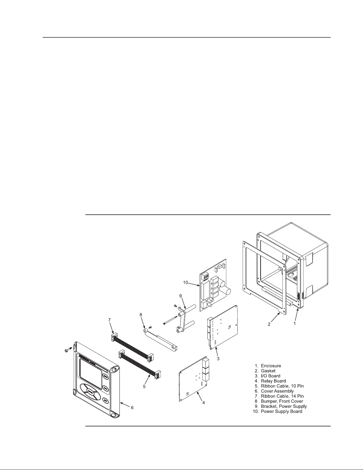
ection 5: Maintenance and Service 6888Xi Advanced Electronics Instruction Manual
S
December 2012 PN 51-6888Xi
5.3 Calibration
The 6888Xi can calibrate an O2Probe manually through the front panel display or via a handheld
375/475 Field Communicator, or automatically through the SPS 4001B Single Probe
Autocalibration Sequencer or the IMPS 4000 Intelligent Multiprobe Test Gas Sequencer.
5.3.1 Automatic Calibration
The 6888Xi can be used with the SPS 4001B or IMPS 4000 in order to perform an auto / semiauto calibration. Refer to the SPS 4001B or IMPS 4000 Instruction Manual for further details on
how to configure and perform an automatic calibration.
5.3.2 Manual Calibration
Refer to the "Calibration - General" in Section 3: Configuration, Startup and Operation to perform
a manual calibration.
FIGURE 5-1. 6888Xi Components
80 Maintenance and Service
Page 89

888Xi Advanced Electronics Instruction Manual Section 5: Maintenance and Service
6
PN 51-6888Xi December 2012
5.4 Replacement Parts
Refer to Section 6: Replacement Parts for individual replacement parts and part replacement
kits. Part replacement kits are available for each of the components discussed in this section.
5.5 6888Xi Component Replacement
Each of the following procedures detail how to replace a specific component of the 6888Xi. Most
of these procedures include component setup instructions that must be performed before
returning the related O2Probe to service. Refer to Figure 5-1 and Figure 5-2 for illustrations of
the 6888Xi components.
5.5.1 I/O Board Replacement
Use the procedure that follows to replace and set up the I/O board in the 6888Xi.
WARNING
Disconnect and lock out power before working on any electrical components.
WARNING
The I/O Board is shipped from the factory without any of the enhanced software features activated.
These features must be activated once the new board has been installed and before the Remote
Interface is put into service.
FIGURE 5-2. 6888Xi Components
Maintenance and Service 81
Page 90

ection 5: Maintenance and Service 6888Xi Advanced Electronics Instruction Manual
6888Xi
6888Xi
6888Xi
6
888Xi
S
December 2012 PN 51-6888Xi
FIGURE 5-3. I/O Board Jumper & Switch Settings
WARNING
If the existing I/O Board has been operated with enhanced software features, these features must be
activated in the new board before the 6888Xi Electronics is put back into service. Failure to do so will
cause a false analog output signal to the DCS.
rd
Boa
ng I/O
sti
i
x
n E
ng a
placi
Re
not need
o
d
d
n
tive a
re cap
nents.
m
p
crews a
o
1. L
2. S
en the four s
oos
e co
b
to
g
win
ely removed
t
ple
m
the 6888X
crews s
i cover d
ecur
.
own to
the 6888X
g
in
ex
i cover. The s
e the inner co
os
p
3. Disconnect the 10-pin ribbon cable from the I/O Board. A new cable is supplied in the
t kit and should be used if the old one is damaged.
t wiring for Alarm Outputs, Flame Status Input and/or SPS/IMPS as appli
c
nne
4
rep
. T
lacemen
ag and disco
cable.
O Board part way out of the 6888Xi enclosure.
I/
e
th
lide
5. S
4-position plug for the transmitter probe and output wiring. Remove the I/O
t the
c
6. Disc
. Se
7
onne
Board co
Figure
e
om the 6888Xi enclosure.
fr
mpletel
y
. Set jumpers JP1, JP2, JP5, JP7 and JP8 to their proper positions using the old
5-3
I/O Board as a guide.
. Set s
8
9. Partially slide the new I/O Board into the 6888Xi enclosure. Ensure the board is correctly
witch
their proper positions using the old I/O Board as a guide.
to
SW4
aligned within the slots in the enclosure.
10. Connect the 4-position plug for the transmitter probe and output wiring. Slide the I/O
Board completely into the 6888Xi enclosure.
-
82 Maintenance and Service
Page 91

888Xi Advanced Electronics Instruction Manual Section 5: Maintenance and Service
6
PN 51-6888Xi December 2012
FIGURE 5-4. I/O Board Wiring Connections
FIGURE 5-5. I/O Board Flame Safety Interlock Wiring
Maintenance and Service 83
Page 92

ection 5: Maintenance and Service 6888Xi Advanced Electronics Instruction Manual
S
December 2012 PN 51-6888Xi
IGURE 5-6. I/O Board Positions in the 6888Xi Enclosure
F
11. Reinstall wiring for Alarm Outputs, Flame Status Input and/or SPS/IMPS as applicable. See
Figure 5-4 and Figure 5-5 for wiring diagrams. See Figure 5-6 for I/O board positions in the
6888Xi enclosure.
12. Connect the ribbon cable to the I/O Board. A new cable is supplied and should be used if the
old one is damaged.
13. Swing the 6888Xi cover up in place and tighten the four screws.
14. Prior to operating the O2Probe and the 6888Xi, all optional software enhancements (previ-
ously enabled or not) must be enabled. Notify Rosemount Analytical Inc. and reference the
following part numbers to enable the related software options:
Part Number Description
6A00269G01 Enhanced Software Option Upgrade, Stoichiometric Function
6A00269G02 Enhanced Software Option Upgrade, Programmable Reference Function
6A00269G03 Enhanced Software Option Upgrade, Extended Temperature Function
6A00267604 Enhanced Software Option Upgrade, Diffuse Warning Function
NOTE
For enhanced software upgrades or to enable optional software features previously used in your 6888Xi
configuration, contact Rosemount Analytical at 1-800-433-6076.
NOTE
The calibration parameters are stored in both the I/O Board and Transmitter Board. When the I/O Board
is replaced, the calibration parameters must be either transferred from the Transmitter Board or the
entire instrument must be recalibrated.
84 Maintenance and Service
Page 93

888Xi Advanced Electronics Instruction Manual Section 5: Maintenance and Service
6
PN 51-6888Xi December 2012
15. Reapply power to the Remote Interface and Probe. When initialization is complete, the
Probe will begin heating up, but an alarm condition will be shown. Prior to using the
Transmitter for measurement purposes, perform one of the following:
a. Recalibrate the O2Probe according to the applicable calibration instructions in Section 3.
b. Synchronize the calibration parameters as follows:
i. Press the <DIAG> button once to view the alarms. A “Probe Changed” alarm will be
shown.
ii. Press the <EXIT> button once to enteer the “Diagnostic Menu”.
iii. Use the Up/Down keys to select “3-Acknowledge Alarms”. Press <ENTER>.
iv. Use the Up/Down keys to select “3-Ack Probe Changed”. Press <ENTER>.
v. Use the Up/Down keys to select “1-Get From Probe”. Press <ENTER> twice.
vi. When transfer is complete, press <EXIT> twice to return to the main menu.
5.5.2 AC Relay Board Replacement
Use the procedure that follows to replace and set up the AC Relay board in the 6888Xi.
WARNING
Disconnect and lock out power before working on any electrical components.
Replacing an 6888Xi AC ReIay Board
1. Loosen the four screws securing the 6888Xi cover. The screws are captive and do not need
to be completely removed.
2. Swing the 6888Xi cover down to expose the inner components.
3. Tag and disconnect wiring for the Relay In.
4. Slide the AC Relay Board part way out of the 6888Xi enclosure.
5. Tag and disconnect the two 3-position plugs for the AC input and transmitter probe heater
wiring. Remove the AC Relay Board completely from the 6888Xi enclosure.
6. Partially slide the new AC Relay Board into the 6888Xi enclosure. Ensure the board is correctly aligned within the slots in the enclosure.
7. Connect the two 3-position plugs for the AC input and transmitter probe heater wiring.
Slide the AC Relay Board fully into the 6888Xi enclosure.
8. Reinstall wiring for Relay In. See Figure 5-7 for wiring diagram.
9. Swing the cover up in place and tighten the four screws.
CAUTION
Installing and configuring an AC Relay Board for the Flame Status Interlock function will dedicate alarm
output 2 for this function. Once configured for Flame Status Interlock, the software will override any
previous alarm assignments for alarm output 2 and not allow it to be used for any other function.
Maintenance and Service 85
Page 94

ection 5: Maintenance and Service 6888Xi Advanced Electronics Instruction Manual
S
December 2012 PN 51-6888Xi
FIGURE 5-7. I/O & AC Relay Board Flame Safety Interlock Wiring
Adding an AC Relay Board to the 6888Xi
1. Loosen the four screws securing the 6888Xi cover. The screws are captive and do not need to
be completely removed.
2. Swing the 6888Xi cover down to expose the inner components.
3. Slide the I/O Board part way out of the 6888Xi enclosure.
4. Make the following jumper and switch settings:
a. Set SW4, Position 4 "ON" and all other positions "OFF".
b. Move the jumpers for both JP1 and JP2 to pins 1 and 2.
5. The I/O Board must be relocated to the right-most slot inside the 6888Xi enclosure. If there
is enough service loop on the 6888Xi wiring, slide the I/O Board completely out of the enclosure and re-install it in the right-most slot. Ensure the board is correctly aligned within the
slots. See Figure 5-8 for the correct location of the I/O Board.
NOTE
An AC Relay Board can only be added to single channel 6888Xi, i.e. only one I/O Board controlling one
O2 Probe. The Flame Status Interlock function requires a contact closure on the digital input of the I/O
Board to indicate a flame is present. When properly connected and configured, AC power will be
applied to the transmitter only when the flame is present.
6. If there is not sufficient wiring, tag and disconnect all wiring, and relocate the board. Then
reinstall the wiring.
7. Partially slide the AC Relay Board into the left-most slot of the 6888Xi enclosure. The component side of the AC Relay board will be to the right with the fuse holder at the top. Ensure the
86 Maintenance and Service
Page 95

888Xi Advanced Electronics Instruction Manual Section 5: Maintenance and Service
6
PN 51-6888Xi December 2012
board is correctly aligned within the slots in the enclosure. See Figure 5-8 for the correct
location of the AC Relay Board.
8. Connect two wires approxmately 6" long each between the "HTR COM" and the "HTR NC"
connections on the I/O Board and the "RELAY IN"connections on the AC Relay Board; observe
polarity. See Figure 5-7 for wiring details.
9. Connect the flame status indicator contact to the "DI+" and "DI-" on the AC Relay Board. See
Figure 5-7 for wiring details.
10. Connect the AC input and output wiring to the Transmitter. See Figure 5-7 for wiring details.
11. Slide the AC Relay Board completely into the 6888Xi enclosure.
12. Swing the cover up in place and tighten the four screws.
5.5.3 Power Supply Board Replacement
Use the procedure that follows to replace the Power Supply board in the 6888Xi. Use this procedure to replace an original Linear Power Supply board or the current configuration Switching
Power Supply board.
WARNING
Disconnect and lock out power before working on any electrical components.
1. Loosen the four screws securing the 6888Xi cover. The screws are captive and do not need
to be completely removed.
2. Swing the 6888Xi cover down to expose the inner components.
3. Refer to the wiring diagram in Figure 5-9. Unplug the AC input wiring plug from the Power
Supply board. A new plug is supplied in the replacement kit and should be used if the
6888Xi plug is damaged.
4. Disconnect the 14-pin ribbon cable from the Power Supply board.
5. Remove the two long screws that secure the bracket (9, Figure 5-1) to the 6888Xi enclosure.
6. Hold the AC input wiring to the right and slide the Power Supply board out of the 6888Xi
enclosure.
7. Install the new mounting bracket (9, Figure 5-1) on the new Power Supply board (10, Figure
5-1). A new bracket and mounting screws are provided in the replacement kit.
FIGURE 5-8. I/O and AC Relay Board Position in 6888Xi Enclosure
Maintenance and Service 87
Page 96

ection 5: Maintenance and Service 6888Xi Advanced Electronics Instruction Manual
S
December 2012 PN 51-6888Xi
FIGURE 5-9. Power Supply Board Wiring
8. Slide the Power Supply board into the mating slots in the 6888Xi Enclosure. Make sure the
board is correctly aligned in the slots.
9. Install and tighten the bracket mounting screws. Two new screws are provided in the
replacement kit and should be used if the 6888Xi screws are damaged.
10. Connect the ribbon cable to the Power Supply board. A new ribbon cable (7, Figure 5-1) is
provided in the replacement kit and should be used if the 6888Xi cable is damaged.
11. Connect the AC power plug to the Power Supply board.
12. Swing the 6888Xi cover up and tighten the four mounting screws.
5.5.4 Front Panel Replacement
Use the procedure that follows to replace the front panel on the 6888Xi.Replacement kits with
and without the CPU board are available. Use the instructions that apply to the replacement kit
you have.
WARNING
Disconnect and lock out power before working on any electrical components.
Replacing Front Panel Assembly without CPU Board
1. Loosen the four screws securing the 6888Xi cover. The screws are captive and do not need
to be completely removed.
2. Swing the 6888Xi cover down to expose the inner components.
3. Disconnect the 14-pin ribbon cable going to the Power Supply board. A new cable is supplied in the replacement kit and should be used if the old one is damaged.
4. Disconnect the 10-pin ribbon cable(s) going to the I/O Board(s). One new cable is supplied
in the replacement kit and should be used if either of the ribbon cables are damaged.
5. Remove the wire hinge from the right side of the 6888Xi cover. A paper clip or similar device
can be inserted into the hole on the left side of the cover to push the hinge out of the cover.
A new hinge pin is supplied in the replacement kit and should be used if the old one is damaged.
88 Maintenance and Service
Page 97

888Xi Advanced Electronics Instruction Manual Section 5: Maintenance and Service
6
PN 51-6888Xi December 2012
6. Position the new front panel assembly in place and reinstall the hinge pin. Ensure the hinge
in is fully seated into the 6888Xi cover.
p
WARNING
Installing and configuring an AC Relay Board for the Flame Status Interlock function will dedicate alarm
output 2 for this function. Once configured for Flame Status Interlock, the software will override any
previous alarm assignments for alarm output 2 and not allow it to be used for any other function.
7. The keypad window on the new front panel may be supplied with interior and exterior pro-
tective membranes. Remove the protective membranes prior to final assembly and use of
the 6888Xi enclosure.
8. Reconnect the 10-pin ribbon cable from the I/O Board.
9. Reconnect the 14-pin ribbon cable from the Power Supply Board.
10. Swing the 6888Xi cover up in place and tighten the four screws.
11. If necessary, reconfigure the appearance of the main display. Refer to Section 3:
Configuration, Startup and Operation.
Replacing Front Panel Assembly without CPU Board
1. Loosen the four screws securing the 6888Xi cover. The screws are captive and do not need to
be completely removed.
2. Swing the 6888Xi cover down to expose the inner components.
3. Disconnect the 14-pin ribbon cable going to the Power Supply board. A new cable is sup-
plied in the replacement kit and should be used if the old one is damaged.
4. Disconnect the 10-pin ribbon cable(s) going to the I/O Board(s). One new cable is supplied
in the replacement kit and should be used if either of the ribbon cables are damaged.
5. Remove the wire hinge from the right side of the 6888Xi cover. A paper clip or similar device
can be inserted into the hole on the left side of the cover to push the hinge out of the cover.
A new hinge pin is supplied in the replacement kit and should be used if the old one is damaged.
6. Place the front panel assembly on the bench. Remove the 4 screws securing the CPU board
to the front cover.
NOTE
Prior to disassembly, observe the position of the plastic bumper with rubber insert as it is installed
over the CPU board. The two longer screws are used on the top edge of the CPU board passing
through the bumper.
7. Lift the CPU board off of the front cover using care not to damage the board.
8. Disconnect the keypad overlay ribbon cable from the CPU board. Discard the used front
cover with the keypad overlay attached.
CAUTION
The new front panel assembly may be supplied with protective clear membranes over the interior
and exterior of the window. Failure to remove the exterior protective membrane may cause the
display to appear distorted. The membrane may be difficult or impossible to remove after extended
use at elevated temperatures.
9. The keypad window on the new front panel may be supplied with interior and exterior pro-
tective membranes. Remove the protective membranes prior to final assembly and use of
the 6888Xi enclosure.
Maintenance and Service 89
Page 98

ection 5: Maintenance and Service 6888Xi Advanced Electronics Instruction Manual
S
December 2012 PN 51-6888Xi
NOTE
Prior to assembly, it is recommended that the inside of the keypad overlay window and LCD display
window be gently cleaned to remove fingerprints and accumulated dust.
10. Clean the inside of the keypad overlay window and LCD display window to remove fingerprints and accumulated dust. Use only a soft cloth; do not use any detergents or chemicals.
11. Connect the keypad overlay ribbon cable on the new front panel assembly to the CPU
board. Use care not to damage the board.
12. Position the CPU board in place in the front panel assembly.
13. Reinstall the bumper and 4 screws to secure the CPU board in place. The two longer screws
are used with the plastic bumper on the top edge of the CPU board.
14. Position the front panel assembly and reinstall the hinge pin. Ensure the hinge pin is fully
seated into the 6888Xi cover.
15. Reconnect the 10-pin ribbon cable from the I/O Board.
16. Reconnect the 14-pin ribbon cable from the Power Supply Board.
17. Swing the 6888Xi cover up in place and tighten the four screws.
18. If necessary, reconfigure the appearance of the main display. Refer to Section 3:
Configuration, Startup and Operation.
5.5.5 DR Board Replacement
Use the procedure that follows to replace the DR board in the 6888Xi that is connected to a
Direct Replacement probe.
WARNING
Disconnect and lock out power before working on any electrical components.
1. Loosen the four screws securing the 6888Xi cover. The screws are captive and do not need
to be completely removed.
2. Swing the 6888Xi cover down to expose the inner components.
3. Slide the DR board part way out of the 6888Xi enclosure.
4. Unplug the wiring harness plug from the connector J8 located on the bottom, left-hand side
of the board. Refer to Figure 5-10.
5. Unplug the wiring harness plugs from the connectors J1, J2, and J3 located on the top, righthand side of the board. Refer to Figure 6-11.
6. Tag and disconnect the wiring to connector J4.
7. Remove the DR board from the 6888Xi enclosure.
8. Partially slide the new DR board into the mating slots in the 6888Xi Enclosure. Make sure
the board is correctly aligned in the slots.
9. Refer to the wiring diagram in Figure 6-10. Reconnect the wiring to connector J4.
10. Connect the wiring harness plugs to connectors J1, J2, J3, and J8.
11. Slide the DR board completely into the 6888Xi enclosure.
NOTE
The calibration parameters are stored in both the I/O Board and Transmitter Board. When the I/O Board
is replaced, the calibration parameters must be either transferred from the Transmitter Board or the
entire instrument must be recalibrated.
90 Maintenance and Service
Page 99

888Xi Advanced Electronics Instruction Manual Section 5: Maintenance and Service
6
PN 51-6888Xi December 2012
12. Reapply power to the Remote Interface and Probe. When initialization is complete, the
Probe will begin heating up, but an alarm condition will be shown. Prior to using the
Transmitter for measurement purposes, perform one of the following:
a. Recalibrate the O2Probe according to the applicable calibration instructions in Section 3.
b. Synchronize the calibration parameters as follows:
i. Press the <DIAG> button once to view the alarms. A “Probe Changed” alarm will be
shown.
FIGURE 5-10. DR Board Wiring, Right-Hand Side
Maintenance and Service 91
Page 100

ection 5: Maintenance and Service 6888Xi Advanced Electronics Instruction Manual
S
December 2012 PN 51-6888Xi
ii. Press the <EXIT> button once to enteer the “Diagnostic Menu”.
iii. Use the Up/Down keys to select “3-Acknowledge Alarms”. Press <ENTER>.
iv. Use the Up/Down keys to select “3-Ack Probe Changed”. Press <ENTER>.
v. Use the Up/Down keys to select “1-Get From Probe”. Press <ENTER> twice.
vi. When transfer is complete, press <EXIT> twice to return to the main menu.
FIGURE 5-11. DR Board Wiring, Left-Hand Side
92 Maintenance and Service
 Loading...