

Page 1
Installation Manual
Part Number 3-9000-771Revision A
May 2012
Daniel
TM
3818 LNG Liquid Ultrasonic Meter
For Cryogenic Liquefied Natural Gas Applications
Page 2

Page 3

Important Safety Instructions
Failure to follow the Installation, operation or maintenance instructions for a Daniel product
could lead to serious injury or death from explosion or exposure to dangerous substances. To
reduce this risk:
• Comply with all information on the product, in this manual, and in any local and national
codes that apply to the product.
• Do not allow untrained personnel to work with this product.
• Use Daniel parts and work procedures specified in this manual.
Daniel Measurement and Control, Inc. (Daniel) designs, manufactures and tests products to
function within specific conditions. Because these products are sophisticated technical
instruments, it is important that the owner and operation personnel strictly adhere both to the
information printed on the product nameplate and to all instructions provided in this manual
prior to installation, operation, and maintenance.
Daniel also urges you to integrate this manual into your training and safety program.
BE SURE ALL PERSONNEL READ AND FOLLOW THE INSTRUCTIONS IN THIS MANUAL AND
ALL NOTICES AND PRODUCT WARNINGS.
Product owners (Purchasers):
• Use the correct product for the environment and pressures present. See technical data
for limitations. If you are unsure, discuss your needs with your Daniel representative.
• Inform and train all personnel in the proper installation, operation, and maintenance of
this product.
• To ensure safe and proper performance, only informed and trained personnel should
install, operate, repair and maintain this product.
• Verify that this is the correct instruction manual for your Daniel product. If this is not
the correct documentation, contact Daniel at 1-713-827-6314. You may also
download the correct manual from:
http://www.daniel.com
• Save this instruction manual for future reference.
• If you resell or transfer this product, it is your responsibility to forward this instruction
manual along with the product to the new owner or transferee.
• ALWAYS READ AND FOLLOW THE INSTALLATION, OPERATIONS, MAINTENANCE AND
TROUBLESHOOTING MANUALS AND ALL PRODUCT WARNINGS AND INSTRUCTIONS.
• Do not use this equipment for any purpose other than its intended service. This may
result in property damage and/or serious personal injury or death.
Page 4

Product operation (Personnel):
• To prevent personal injury, personnel must follow all instructions of this manual prior to
and during operation of the product.
• Follow all warnings, cautions, and notices marked on, and supplied with, this product.
• Verify that this is the correct instruction manual for your Daniel product. If this is not
the correct documentation, contact Daniel at 1-713-827-6314. You may also download
the correct manual from:
http://www.daniel.com
• Read and understand all instructions and operating procedures for this product.
• If you do not understand an instruction, or do not feel comfortable following the
instructions, contact your Daniel representative for clarification or assistance.
• Install this product as specified in the INSTALLATION section of this manual per
applicable local and national codes.
• Follow all instructions during the installation, operation, and maintenance of this
product.
• Connect the product to the proper pressure sources when and where applicable.
• Use only replacement parts specified by Daniel. Unauthorized parts and procedures can
affect this product's performance, safety, and invalidate the warranty. "Look-a-like"
substitutions may result in deadly fire, explosion, release of toxic substances or
improper operation.
• Save this instruction manual for future reference.
Page 5
Signal words and symbols used in this manual
Pay special attention to the following signal words, safety alert symbols and statements:
Indicates a hazardous situation which, if not avoided, will result in death or serious injury.
Indicates a hazardous situation which, if not avoided, could result in death or serious injury.
Indicates a hazardous situation which, if not avoided, could result in minor or moderate injury.
Used to address practices associated with possible equipment damage and miscellaneous
practices not related to personal injury.
Safety alert symbol
This is a safety alert symbol. It is used to alert you to potential physical injury hazards. Obey all
safety messages that follow this symbol to avoid possible injury or death.
Page 6

Daniel Measurement and Control, Inc.
COPYRIGHT
©
2012 BY DANIEL MEASUREMENT AND CONTROL, INC., HOUSTON, TEXAS, U.S.A.
All rights reserved. No part of this work may be reproduced or copied in any form or by any means - graphic,
electronic, or mechanical – without first receiving the written permission of Daniel Measurement and Control,
Inc. Houston, Texas, U.S.A.
DanielTM 3818 Liquid Ultrasonic Flow Meters
NOTICE
THE CONTENTS OF THIS PUBLICATION ARE PRESENTED FOR INFORMATIONAL PURPOSES ONLY, AND WHILE EVERY
EFFORT HAS BEEN MADE TO ENSURE THEIR ACCURACY, THEY ARE NOT TO BE CONSTRUED AS WARRANTIES OR
GUARANTEES, EXPRESSED OR IMPLIED, REGARDING THE PRODUCTS OR SERVICES DESCRIBED HEREIN OR THEIR
USE OR APPLICABILITY. ALL SALES ARE GOVERNED BY DANIEL'S TERMS AND CONDITIONS, WHICH ARE AVAILABLE
UPON REQUEST. WE RESERVE THE RIGHT TO MODIFY OR IMPROVE THE DESIGNS OR SPECIFICATIONS OF SUCH
PRODUCTS AT ANY TIME.
DANIEL DOES NOT ASSUME RESPONSIBILITY FOR THE SELECTION, USE OR MAINTENANCE OF ANY PRODUCT.
RESPONSIBILITY FOR PROPER SELECTION, USE AND MAINTENANCE OF ANY DANIEL PRODUCT REMAINS SOLELY
WITH THE PURCHASER AND END-USER.
TO THE BEST OF DANIEL'S KNOWLEDGE THE INFORMATION HEREIN IS COMPLETE AND ACCURATE. DANIEL MAKES
NO WARRANTIES, EXPRESSED OR IMPLIED, INCLUDING THE IMPLIED WARRANTIES OF MERCHANTABILITY AND
FITNESS FOR A PARTICULAR PURPOSE WITH RESPECT TO THIS MANUAL AND, IN NO EVENT, SHALL DANIEL BE
LIABLE FOR ANY INCIDENTAL, PUNITIVE, SPECIAL OR CONSEQUENTIAL DAMAGES INCLUDING, BUT NOT LIMITED
TO, LOSS OF PRODUCTION, LOSS OF PROFITS, LOSS OF REVENUE OR USE AND COSTS INCURRED INCLUDING
WITHOUT LIMITATION FOR CAPITAL, FUEL AND POWER, AND CLAIMS OF THIRD PARTIES.
PRODUCT NAMES USED HEREIN ARE FOR MANUFACTURER OR SUPPLIER IDENTIFICATION ONLY AND MAY BE
TRADEMARKS/REGISTERED TRADEMARKS OF THESE COMPANIES.
DANIEL AND THE DANIEL LOGO ARE REGISTERED TRADEMARKS OF DANIEL INDUSTRIES, INC. THE EMERSON LOGO
IS A TRADEMARK AND SERVICE MARK OF EMERSON ELECTRIC CO.
.
Page 7

Warranty
1. LIMITED WARRANTY: Subject to the limitations contained in Section 2 herein, Daniel Measurement &
Control, Inc. ("Daniel") warrants that the licensed firmware embodied in the Goods will execute the
programming instructions provided by Daniel, and that the Goods manufactured by Daniel will be free from
defects in materials or workmanship under normal use and care and Services will be performed by trained
personnel using proper equipment and instrumentation for the particular Service provided. The foregoing
warranties will apply until the expiration of the applicable warranty period. Goods are warranted for twelve
(12) months from the date of initial installation or eighteen (18) months from the date of shipment by Daniel,
whichever period expires first. Consumables and Services are warranted for a period of 90 days from the date
of shipment or completion of the Services. Products purchased by Daniel from a third party for resale to Buyer
("Resale Products") shall carry only the warranty extended by the original manufacturer. Buyer agrees that
Daniel has no liability for Resale Products beyond making a reasonable commercial effort to arrange for
procurement and shipping of the Resale Products. If Buyer discovers any warranty defects and notifies Daniel
thereof in writing during the applicable warranty period, Daniel shall, at its option, correct any errors that are
found by Daniel in the firmware or Services or repair or replace F.O.B. point of manufacture that portion of the
Goods or firmware found by Daniel to be defective, or refund the purchase price of the defective portion of the
Goods/Services. All replacements or repairs necessitated by inadequate maintenance, normal wear and usage,
unsuitable power sources or environmental conditions, accident, misuse, improper installation, modification,
repair, use of unauthorized replacement parts, storage or handling, or any other cause not the fault of Daniel
are not covered by this limited warranty, and shall be at Buyer's expense. Daniel shall not be obligated to pay
any costs or charges incurred by Buyer or any other party except as may be agreed upon in writing in advance
by Daniel. All costs of dismantling, reinstallation and freight and the time and expenses of Daniel's personnel
and representatives for site travel and diagnosis under this warranty clause shall be borne by Buyer unless
accepted in writing by Daniel. Goods repaired and parts replaced by Daniel during the warranty period shall be
in warranty for the remainder of the original warranty period or ninety (90) days, whichever is longer. This
limited warranty is the only warranty made by Daniel and can be amended only in a writing signed by Daniel.
THE WARRANTIES AND REMEDIES SET FORTH ABOVE ARE EXCLUSIVE. THERE ARE NO REPRESENTATIONS OR
WARRANTIES OF ANY KIND, EXPRESS OR IMPLIED, AS TO MERCHANTABILITY, FITNESS FOR PARTICULAR
PURPOSE OR ANY OTHER MATTER WITH RESPECT TO ANY OF THE GOODS OR SERVICES. Buyer acknowledges
and agrees that corrosion or erosion of materials is not covered by this warranty.
2. LIMITATION OF REMEDY AND LIABILITY
PERFORMANCE. THE REMEDIES OF BUYER SET FORTH IN THIS AGREEMENT ARE EXCLUSIVE. IN NO EVENT,
REGARDLESS OF THE FORM OF THE CLAIM OR CAUSE OF ACTION (WHETHER BASED IN CONTRACT,
INFRINGEMENT, NEGLIGENCE, STRICT LIABILITY, OTHER TORT OR OTHERWISE), SHALL DANIEL'S LIABILITY TO
BUYER AND/OR ITS CUSTOMERS EXCEED THE PRICE TO BUYER OF THE SPECIFIC GOODS MANUFACTURED OR
SERVICES PROVIDED BY DANIEL GIVING RISE TO THE CLAIM OR CAUSE OF ACTION. BUYER AGREES THAT IN NO
EVENT SHALL DANIEL'S LIABILITY TO BUYER AND/OR ITS CUSTOMERS EXTEND TO INCLUDE INCIDENTAL,
CONSEQUENTIAL OR PUNITIVE DAMAGES. THE TERM "CONSEQUENTIAL DAMAGES" SHALL INCLUDE, BUT NOT
BE LIMITED TO, LOSS OF ANTICIPATED PROFITS, REVENUE OR USE AND COSTS INCURRED INCLUDING
WITHOUT LIMITATION FOR CAPITAL, FUEL AND POWER, AND CLAIMS OF BUYER'S CUSTOMERS.
: DANIEL SHALL NOT BE LIABLE FOR DAMAGES CAUSED BY DELAY IN
Page 8

Page 9

Daniel 3818 LNG Liquid Ultrasonic Meter Installation Manual Table of Contents
3-9000-771 Rev A May 2012
Contents
Important Safety Instructions
Section 1: Introduction
1.1 Typical Applications .................................................................................... 1
1.2 Features and benefits: ................................................................................. 1
1.3 Acronyms, abbreviations and definitions ....................................................... 2
1.4 Daniel MeterLink software ........................................................................... 5
1.5 3818 LNG Liquid Ultrasonic Flow Meter design .............................................. 6
1.6 Meter specifications .................................................................................... 8
1.7 Pre-installation considerations ................................................................... 11
1.8 Safety ...................................................................................................... 11
1.9 Certifications and approvals....................................................................... 12
1.10 FCC compliance....................................................................................... 13
Section 2: Mechanical installation
2.1 Meter piping, lifting and mounting ............................................................. 15
2.2 Meter components .................................................................................... 17
2.3 Piping recommendations ........................................................................... 18
2.4 Field hydrostatic pressure testing ............................................................... 21
2.5 Meter safety for hoist rings and lifting slings ............................................... 22
2.5.1 Use of appropriate safety engineered swivel hoist rings
in meter end flanges ....................................................................................... 23
2.5.2 Appropriately rated lifting slings ..................................................................... 28
2.6 Mounting requirements in Liquefied Natural Gas pipelines ........................... 31
Section 3: Electrical installation
3.1 Cable length TTL mode .............................................................................. 35
3.2 Cable length Open Collector mode ............................................................. 35
3.3 Grounding meter electronics ..................................................................... 36
3.4 Conduit seals ............................................................................................ 38
3.4.1 Startup for systems using explosion-proof conduit ......................................... 39
3.4.2 Startup for systems that use flame-proof cable ............................................... 40
3.5 Wiring and I/O .......................................................................................... 41
3.5.1 CPU Module labeling and LED indicators......................................................... 42
Table of Contents i
Page 10

Table of Contents Daniel 3818 LNG Liquid Ultrasonic Meter Installation Manual
May 2012 3-9000-771 Rev A
3.6 Daniel Ultrasonic Meters I/O connections ....................................................47
3.6.1 Frequency/Digital outputs...............................................................................48
3.6.2 Analog input settings ......................................................................................52
3.6.3 Analog output settings....................................................................................52
3.6.4 Digital Input ....................................................................................................52
3.6.5 DHCP server switch settings ............................................................................53
3.6.6 Configuration protect switch settings .............................................................53
3.6.7 External power source connection and fuse.....................................................53
3.6.8 Securing the meter..........................................................................................54
3.6.9 Sealing the unit ...............................................................................................57
Section 4: Configuring a 3818 LNG Meter
4.1 Using Daniel MeterLink to configure the meter ............................................59
4.1.1 Field Setup Wizard using Daniel MeterLink ......................................................61
4.2 Using AMS Device Manager to configure the meter...................................... 62
4.3 Using a Field Communicator to configure the meter ....................................77
4.4 Security seals for the meter ........................................................................80
Appendix A: Engineering drawings
A.1 Daniel 3818 LNG Liquid Ultrasonic Flow Meter drawings ................................................... 81
Appendix B: Open source licenses
B.1 GNU General Public License............................................................................................... 84
B.2 GNU Lesser General Public License .................................................................................... 95
B.3 BSD Open Source License.................................................................................................. 99
B.4 M.I.T License ................................................................................................................... 100
Appendix C: Index
C.1 Manual index................................................................................................................... 101
ii Table of Contents
Page 11

Daniel 3818 LNG Liquid Ultrasonic Meter Installation Manual List of Tables
3-9000-771 Rev A May 2012
List of Tables
Table 1-1 Acronyms, abbreviations and definitions........................................................................ 2
Table 1-2 Meter specifications ....................................................................................................... 8
Table 2-1 Hoist ring part number................................................................................................. 27
Table 2-2 Hoist ring table for Daniel 3818 LNG Liquid Ultrasonic Flow Meters ............................. 27
Table 3-1 Configurations for open collector frequency outputs ................................................... 35
Table 3-2 CPU Module labeling and LED functions........................................................................ 43
Table 3-3 Ethernet cable to PC communication ........................................................................... 44
Table 3-4 Serial Port A parameters ............................................................................................... 45
Table 3-5 Frequency/Digital Outputs possible configurations ...................................................... 50
Table 3-6 DHCP server switch settings ......................................................................................... 53
Table 3-7 Configuration protect switch settings .......................................................................... 53
Table B-1 Open source licences ................................................................................................... 83
List of Tables iii
Page 12

List of Tables Daniel 3818 LNG Liquid Ultrasonic Meter Installation Manual
May 2012 3-9000-771 Rev A
iv List of Tables
Page 13

Daniel 3818 LNG Liquid Ultrasonic Meter Installation Manual List of Figures
3-9000-771 Rev A May 2012
List of Figures
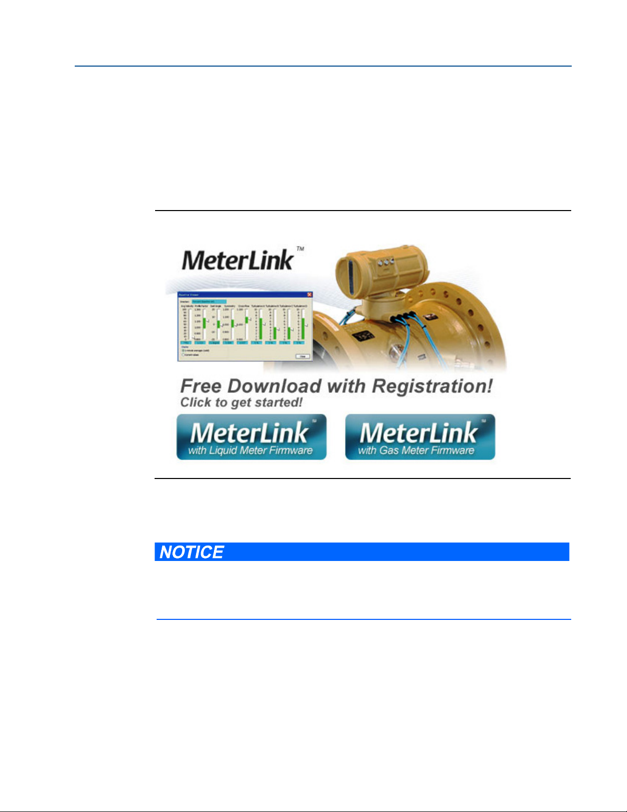
Figure 1-1 Daniel MeterLink download and registration ................................................................ 5
Figure 1-2 3818 LNG Meter with remote mount electronics and band shroud assembly................ 6
Figure 1-3 Daniel 3810 Series Liquid Ultrasonic Meter ATEX approval ......................................... 12
Figure 2-1 Daniel 3818 Liquid Ultrasonic Flow Meter assembly .................................................. 17
Figure 2-2 Piping recommendations unidirectional flow.............................................................. 19
Figure 2-3 Piping recommendations bidirectional flow................................................................ 19
Figure 2-4 Meter end flange with tapped flat-counterbore hole for hoist ring ............................ 23
Figure 2-5 Safety approved hoist ring and non-compliant eye bolt ............................................. 24
Figure 2-6 90 Degree angle between slings ................................................................................. 25
Figure 2-7 Incorrect sling attachment ......................................................................................... 26
Figure 2-8 Correct sling attachment with spreader bar ............................................................... 29
Figure 2-9 Incorrect sling attachment.......................................................................................... 30
Figure 2-10 Transducer cabling conduit......................................................................................... 32
Figure 3-1 Internal Transmitter Electronics Enclosure chassis ground .......................................... 36
Figure 3-2 External ground lug .................................................................................................... 37
Figure 3-3 CPU Module labeling and LED indicators ..................................................................... 42
Figure 3-4 PC to meter serial connection wiring ........................................................................ 46
Figure 3-5 CPU Module I/O connections...................................................................................... 47
Figure 3-6 CPU Module - Frequency/Digital inputs common ground ........................................... 51
Figure 3-7 CPU Module power source connections ..................................................................... 53
Figure 3-8 Transmitter electronic enclosure security latch .......................................................... 54
Figure 3-9 Transmitter Electronics Enclosure security seal installation ........................................ 55
Figure 3-10 Base Enclosure wire seal installation ........................................................................... 56
Figure 4-1 Daniel MeterLink - Meter Directory ............................................................................ 59
Figure 4-2 AMS Device Description search................................................................................... 62
Figure 4-3 AMS file download complete ...................................................................................... 63
Figure 4-4 AMS Device Manager ................................................................................................ 64
Figure 4-5 AMS Device Manager - Overview ............................................................................... 64
Figure 4-6 AMS Device Manager - Guided Setup ......................................................................... 65
Figure 4-7 AMS Device Manager - Zero Flow .............................................................................. 66
Figure 4-8 AMS Device Manager - Service Tools All Variables status indicators............................. 68
Figure 4-9 Display Meter K-Factors .............................................................................................. 68
Figure 4-10 AMS Device Manager - Configure Manual Setup.......................................................... 69
List of Figures v
Page 14

List of Figures Daniel 3818 LNG Liquid Ultrasonic Meter Installation Manual
May 2012 3-9000-771 Rev A
Figure 4-11 Gating configuration parameter Edge gated, active high ............................................71
Figure 4-12 Gating configuration parameter Edge gated, active low..............................................71
Figure 4-13 Gating configuration parameter State gated, active high............................................71
Figure 4-14 Gating configuration parameter State gated, active low .............................................71
Figure 4-15 Configure Flow Analysis Alert .....................................................................................72
Figure 4-16 AMS Device Manager - Service Tools Alerts .................................................................73
Figure 4-17 Configuration changes dialog .....................................................................................73
Figure 4-18 AMS Device Manager - Service Tools ..........................................................................74
Figure 4-19 AMS Device Manager - Service Tools All Variables ......................................................75
Figure 4-20 AMS Device Manager - Service Tools Trends ..............................................................76
Figure 4-21 3818 transmitter field wiring conduit entries ..............................................................78
Figure 4-22 Field Communicator wiring diagram for the 3818 LNG Meter ....................................79
vi List of Figures
Page 15

Daniel 3818 LNG Liquid Ultrasonic Meter Installation Manual Section 1: Introduction
3-9000-771 Rev A May 2012
Section 1: Introduction
Daniel 3818 LNG Liquid Ultrasonic Flow Meters have various configurations that meet a broad
range of customer requirements. Each meter comes fully assembled from Daniel
Measurement and Control, Inc. and all parts and assemblies are tested prior to shipment.
Refer to the following documents for additional details:
• P/N 3-9000-762 HART® Field Device Specification Guide Liquid Ultrasonic Meter
• P/N 3-9000-772 Daniel 3818 LNG Liquid Ultrasonic Flow Meter Maintenance and
Troubleshooting Manual
1.1 Typical Applications
• Custody transfer measurement
• Allocation measurement
• LNG applications
- LNG liquefaction to storage (loading terminals)
- LNG liquefaction loading (loading terminal)
- LNG receiving to storage (receipt terminal)
- LNG storage to regasification (receipt terminal)
1.2 Features and benefits:
• Two remote mountable explosion-proof transmitter electronics enclosures with CPU
Module, Power Supply, Intrinsic Safety Barrier Module and Backplane
TM
• Two remote mountable intrinsically safe transmitter electronics enclosures with the
Acquisition Module
• Transducer housings seal-welded to meter body to eliminate leak potential
• Meter body insulated and shroud assembly covering transducers and cabling
• HART®
architecture
• Suitable for measuring process fluid temperature ranges from -196
to +60
• Reduce unaccounted measurement
• Extensive self diagnostics
• Immediate alarm reporting
• Auto-detected ASCII/RTU Modbus communications protocol
and AMS Suite: Intelligent Device Manager communications for PlantWebTM
o
C (-321 oF)
o
C (140 oF)
Section 1: Introduction 1
Page 16

Section 1: Introduction Daniel 3818 LNG Liquid Ultrasonic Meter Installation Manual
May 2012 3-9000-771 Rev A
• Internet-ready communications
• Ethernet access
• Modbus TCP/IP
• On-board LED status indicators
• Analog pressure and temperature inputs
TM
• Daniel MeterLink
(a Windows®-based interface software)
1.3 Acronyms, abbreviations and definitions
Table 1-1 Acronyms, abbreviations and definitions
Acronym or abbreviation Definition
°degree (angle)
o
C
o
F
ADC analog-to-digital converter
AI analog input
AMS® Suite Device Manager Asset Management Software - Device Manager
AO analog output
ASCII MODBUS A Modbus protocol message framing format in which ASCII characters are used to
Backplane board Backplane board for CPU board, I.S Barrier board, Power Supply, and Acquisition
boolean A type of data point that can only take on values of TRUE or FALSE (generally TRUE is
bps Bits per second (baud rate)
cPoise Centipoise (viscosity unit)
CPU Central Processing Unit
CTS Clear-to-Send; the RS-232C handshaking signal input to a transmitter indicating that
DAC Digital-to-Analog Converter
Daniel MeterLink
DI Digital Input
DO Digital Output
DHCP Dynamic Host Configuration Protocol
dm
ECC Error Correction Code
EEPROM Electrically-Erasable, Programmable Read-Only Memory
Flash non-volatile, programmable read-only memory
3
f
3
f
/s
TM
degrees celsius (temperature unit)
degrees fahrenheit (temperature unit)
delineate the beginning and end of the frame. ASCII stands for American Standard
Code for Information Interchange.
cable connections
represented by a value of 1, FALSE is represented by a value of 0)
it is okay to transmit data – i.e., the corresponding receiver is ready to receive data.
Generally, the Request-to-Send (RTS) output from a receiver is input to the Clear-toSend (CTS) input of a transmitter.
Daniel Ultrasonic Meter interface software
-1
decimeter (10
cubic foot
Cubic foot per second
meters, length unit)
2 Acronyms, abbreviations and definitions
Page 17

Daniel 3818 LNG Liquid Ultrasonic Meter Installation Manual Section 1: Introduction
3-9000-771 Rev A May 2012
Table 1-1 Acronyms, abbreviations and definitions
Acronym or abbreviation Definition
f3/min
FODO Output that is user configurable as either a frequency or digital output
Gal Gallon
HART® Communication Protocol Highway Addressable Remote Transducer communications protocol
hr hour (time unit)
Hz Hertz (cycles per second, frequency unit)
I/O Input/Output
IS Intrinsically Safe
K Kelvin (temperature unit)
kHz
LAN Local Area Network
LED lIght-emitting Diode
LLiters
m meter (length unit)
3
/d
m
3
m
/h
3
m
/s
mA milliamp (current unit)
MAC Address Media Access Control (Ethernet Hardware Address -EHA)
Cubic foot per minute
3
Kilohertz (10
cycles per second, frequency unit)
cubic meters per day (volumetric flow rate)
cubic meters per hour (volumetric flow rate)
cubic meters per second (volumetric flow rate)
microinch (
micron
inch)
microinch (10-6 in)
micrometer (10-6 m)
MMU Memory Management Unit
MPa
Megapascal (equivalent to 10
6
Pascal) (pressure unit)
N/A Not Applicable
Nm3/h
normal cubic meters per hour
NOVRAM Non-volatile Random Access Memory
Pa Pascal, equivalent to 1 newton per square meter (pressure unit)
Pas Pascal Second (viscosity unit)
PC Personal Computer
Acronyms, abbreviations and definitions 3
Page 18
Section 1: Introduction Daniel 3818 LNG Liquid Ultrasonic Meter Installation Manual
May 2012 3-9000-771 Rev A
Table 1-1 Acronyms, abbreviations and definitions
Acronym or abbreviation Definition
P/N part number
PS power supply (board)
psi pounds per square inch (pressure unit)
psia pounds per square inch absolute (pressure unit)
psig pounds per square inch gage (pressure unit)
RRadius
rad radian (angle)
RAM Random Access Memory
RTS Request-to-Send; the RS-232C handshaking signal output by a receiver when it is
ready to receive data
RTU MODBUS A Modbus protocol framing format in which elapsed time between received charac-
s second (time unit, metric)
SDRAM Synchronous Dynamic Random Access Memory
sec second (time unit, u.s. customary)
TCP/IP Transmission Control Protocol/Internet Protocol
time_t seconds since Epoch (00:00:00 UTC Jan. 1, 1970) (time unit)
UDP User Datagram Protocol
U.L. Underwriters Laboratories, Inc. - product safety testing
V Volts (electric potential unit)
W Watts (power unit)
ters is used to separate messages. RTU stands for Remote Terminal Unit.
and certification organization
4 Acronyms, abbreviations and definitions
Page 19
Daniel 3818 LNG Liquid Ultrasonic Meter Installation Manual Section 1: Introduction
After the download, follow the instructions in the Readme file. Do not attempt to unzip the
zipped firmware file. Daniel MeterLink unzips the compressed file using the
Too ls >P ro gr am
Download
utility.
3-9000-771 Rev A May 2012
1.4 Daniel MeterLink software
Daniel MeterLink software has robust features for setting communications parameters,
calibrating your meter, collecting logs and reports and monitoring the meter health and alarm
statuses. Daniel MeterLink may be downloaded at no charge from:
http://www2.emersonprocess.com/en-US/brands/daniel/Flow/ultrasonics/Pages/MeterLink.aspx
Figure 1-1 Daniel MeterLink download and registration
Select the MeterLink software and firmware bundle appropriate for your meter. Complete the
Online registration form and you will receive a conformation email with a hyperlink directing
you to the download site.
Refer to the Daniel MeterLink Software for Gas and Liquid Ultrasonic Meters Quick Start Manual
(P/N 3-9000-763) for installation instructions and to setup initial communications. You may
download the manual from the Daniel MeterLink web page:
http://www2.emersonprocess.com/en-US/brands/daniel/Flow/ultrasonics/Pages/MeterLink.aspx
Daniel MeterLink software 5
Page 20

Section 1: Introduction Daniel 3818 LNG Liquid Ultrasonic Meter Installation Manual
A. Explosion-proof transmitter enclosure
B. Bracket cover with synchronization cable
C. Intrinsically-safe base enclosure includes Acquisition Module
A.
C.
E.
D.
D. Rigid and flexible conduit for transducer cables
(CPU Module, Power Supply, I.S. Barrier Board, and Backplane Bd.)
B.
E. Meter - body and shroud cover for transducers and cables assemblies
May 2012 3-9000-771 Rev A
1.5 3818 LNG Liquid Ultrasonic Flow Meter design
The Daniel 3818 LNG Liquid Ultrasonic Flow Meter is a remote mount, dual transmitter
electronics, eight-path (sixteen transducers) in-line meter designed to measure the difference in
signal transit time with and against the flow across one or more measurement path(s). A signal
transmitted with the direction of flow travels faster than one transmitted against the flow
direction. Each measurement path is defined by a transducer pair in which each transducer
alternately acts as transmitter and receiver. The meter uses transit time measurements and
transducer location information to calculate the mean velocity.
Figure 1-2 3818 LNG Meter with remote mount electronics and band shroud assembly
6 3818 LNG Liquid Ultrasonic Flow Meter design
Page 21

Daniel 3818 LNG Liquid Ultrasonic Meter Installation Manual Section 1: Introduction
3-9000-771 Rev A May 2012
Computer simulations of various velocity profiles demonstrate that eight measurement paths
provide an optimum solution for measuring asymmetric flow. The Daniel 3818 LNG Liquid
Ultrasonic Flow Meter utilizes eight cross-bore, parallel-plane measurement paths to offer a high
degree of accuracy, repeatability, and superior low-flow capabilities without the compromises
associated with conventional technologies. The meter is comprised of two 3810 Transmitter
Electronics, designated as co-located primary (master) and secondary (slave) electronics. A synchronization cable connects the primary and secondary Acquisition Modules at the J6 terminal
block and the liquid ultrasonic flow meter firmware controls the transducers firing sequencing.
The Daniel 3818 LNG Liquid Ultrasonic Flow Meter with the 30” diameter meter body utilizes 60
degree port angles with LT-07 transducers.
These features make the Daniel 3818 LNG Liquid Ultrasonic Flow Meter the best choice for
cryogenic custody transfer applications as shown in the following sections of this manual.
The Daniel 3818 LNG Liquid Ultrasonic Flow Meter’s U.L. safety listing is accomplished through
the combination of a remote mounted, explosion-proof Transmitter Electronics Enclosure that
houses the CPU Module, I.S. Barrier Module, Power Supply Board, and the Backplane Board. The
flameproof Base Electronics Enclosure houses the Acquisition Module and the acquisition board
cable connections. The intrinsically safe transducers and cable assemblies are designed for Class
1, Division 1, Groups C and D areas without need of further protection when installed in
accordance with the field wiring diagram (refer to Daniel drawing DMC - 004936, see
Appendix A) and the meter body (spool piece).
3818 LNG Liquid Ultrasonic Flow Meter design 7
Page 22
Section 1: Introduction Daniel 3818 LNG Liquid Ultrasonic Meter Installation Manual
May 2012 3-9000-771 Rev A
1.6 Meter specifications
Specifications for Daniel 3818 LNG Liquid Ultrasonic Flow Meters are below:
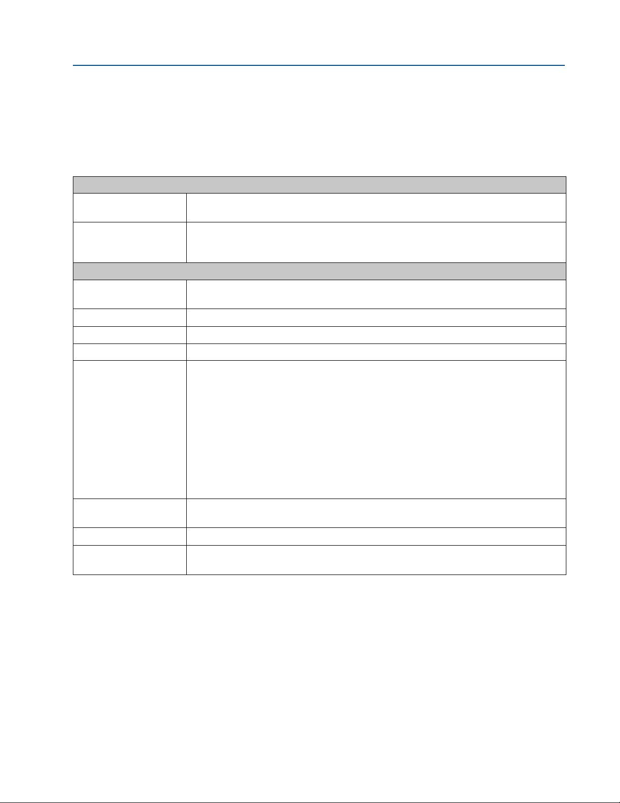
Table 1-2 Meter specifications
Liquid meter specifications
Meter type Number of paths:
• Eight path (sixteen transducer) chordal design
Ultrasonic type:
• Transit-time based measurement
• Spool piece with integral mount transducers
Meter performance
Linearity
Repeatability
Velocity range
Upper Viscosity Limit
Body and Flange Pressure
rating range
Flange types
Specific Gravity
Accuracy Limits
• ± 0.15% of measured value over a 10:1 turndown
• ± 0.20% of measured value over a 20:1 turndown
• ±0.02% of reading in the specified velocity range
• 2.0 fps (0.6 m/s) to 40.0 fps (12.2 m/s) (nominal) 48 fps (14.3 m/s) (over-range)
• 150 centipoise (Transducers LT-07)
U.S. Customary Units - Meter size 30 (Raised face, RTJ or Companion)
• Line sizes:
— 30” (DN 900)
• ANSI pressure classes (per ANSI B16.5):
— 300 ANSI / PN 50
• Body and flange material and temperature rating:
— 316 Stainless steel (forged) body and flanges: (-196° C to 60° C)
• Maximum Pressures
— Dependent on operating temperature
• Minimum Pressures
— 0 psig 0 barg
• Raised face for:
• ANSI class - 300
• 0.35 to 1.50
• Accuracy limits typically are:
— ± 2% without a flow calibration
8 Meter specifications
Page 23
Daniel 3818 LNG Liquid Ultrasonic Meter Installation Manual Section 1: Introduction
3-9000-771 Rev A May 2012
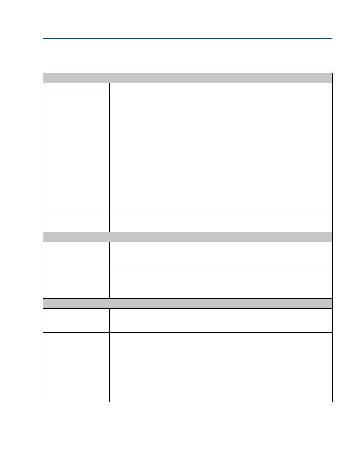
Table 1-2 Meter specifications
Electronic specifications
Power Meter
Tem p er at u re
flameproof Transmitter
Electronic Enclosure and
Base Electronics Enclosure
• 10.4 VDC to 36 VDC
• 11 W typical power consumption
Serial cable
• Belden #9940 or equivalent (22 gauge)
— Capacitance (pF/m) 121.397 (conductor to conductor)
— Capacitance (pF/m) 219.827 (conductor to other conductor and shield)
— Resistance (DC) DCR @ 20°C (Ohm/km) 48.2307
Nominal Outer shield resistance - DCR @ 20°C (Ohm/km) 16.405
— Operating voltage - 300 V RMS (UL AWM Style 2464)
— Current 2.4 Amps per conductor @ 25°C (recommended)
Ethernet cable
• Cat-5 Standard 100Mbps
Frequency (
see Table 3-5)
• 22 AWG wire characteristics are as follows:
— Capacitance = 20 pF/ft or 20 nF/1000 ft (between two wires)
— Resistance = 0.0168 Ohms/ft or 16.8 Ohms/1000 ft
— Pull-up voltage is 24 VDC
Tr an sd u ce rs
• LT- 07
• Operating Temperature Range -321
o
F to +140 oF (-196 oC to 60 oC)
Communications specifications
Connectivity protocols One serial RS-232/RS-485 ports (115 kbps baud rate) (Modbus RTU/ASCII)
• (1) Serial Port A
(RS-232/RS-485 Full Duplex/RS-485 Half Duplex)
One Ethernet Port (TCP/IP) 100 BaseT
• Up to 10 Mbps
• Modbus TCP
Device compatibility FloBoss 103, FloBoss S600 flow computer, ROC 107
Digital, analog, and frequency inputs
Digital Input(s)
(Selectable)
(1) Single polarity (for flow calibration gating - contact closure)
• Single input for starting and stopping
• Four pulse configurations available
Analog Input(s) (2) 4-20 mA
• AI-1 Temperature
• AI-2 Pressure
Note: The analog-to-digital conversion accuracy is within ±0.05% of full scale over the operating
temperature range.
Note: AI-1 and AI-2 are electronically isolated and operate in sink mode. The input contains a
series resistance so HART® Communicators can be connected to configure sensors.
A 24 Volt DC power supply is available to provide power to the sensors.
Meter specifications 9
Page 24

Section 1: Introduction Daniel 3818 LNG Liquid Ultrasonic Meter Installation Manual
May 2012 3-9000-771 Rev A
Table 1-2 Meter specifications
Digital, analog, and frequency outputs
Frequency/Digital
Output(s)
The meter has user-configurable selections for either a Frequency Output or Digital status
(FODO) (Also
(3) Frequency/Digital Outputs
see Section 3.6.1)
• FODO1 (four possible output configurations)
• FODO2(eight possible output configurations)
• FODO3(eight possible output configurations)
Frequency or Digital Output parameter pairs (
Frequency or Digital Outputs (FODO 1) source selections:
see Section 3.6.1)
• (FO1A, DO1A, FO1B, DO1B)
Frequency or Digital Outputs (FODO 2) source selections
• (FO1A, DO1A, FO1B, DO1B, FO2A, DO2A, FO2B, DO2B)
Frequency or Digital Outputs (FODO 3) source selections
• (FO1A, DO1A, FO1B, DO1B, FO2A, DO2A, FO2B, DO2B)
Mode options:
• Open Collector (requires external excitation supply voltage and pull-up resistor)
• TTL (internally powered by the meter 0-5 VDC signal)
Channel B Phase options:
• Lag forward, Lead reverse (Phase B lags Phase A while reporting forward flow, leads Phase A
while reporting reverse flow)
• Lead forward, Lag reverse (Phase B leads Phase A while reporting forward flow, lags Phase A
while reporting reverse flow)
Phase A and Phase B output (based on flow direction)
• Reverse flow - output only reports flow in the reverse direction. For frequency outputs,
Phase B of the output is 90 degrees out of phase with Phase A.
• Forward flow - output only reports flow in the forward direction. For frequency outputs,
Phase B of the output is 90 degrees out of phase with Phase A.
• Absolute - output reports flow in both directions. For frequency outputs, Phase B of the
output is 90 degrees out of phase with Phase A.
• Bidirectional - output reports flow on Phase A only in the forward direction and on Phase B
only in the reverse direction.
Maximum frequency for the frequency outputs
• 1000Hz
• 5000Hz
Analog Output(s)
10 Meter specifications
• (2) 4-20 mA independently configurable analog outputs
The analog output zero scale offset error is within ±0.1% of full scale and gain error is within
±0.2% of full scale. The total output drift is within ±50 ppm of full scale per °C.
Page 25

Daniel 3818 LNG Liquid Ultrasonic Meter Installation Manual Section 1: Introduction
EXPLOSION OR FIRE HAZARD
Read and follow the instructions below:
• Conduit runs must have a sealing fitting within 457mm (18 inches) of the enclosure to reduce the
risk of an explosion or a fire.
• During operation, keep covers tightly closed. DO NOT open the transmitter electronics
enclosures when an explosive atmosphere may be present.
• During equipment maintenance, disconnect power before opening the transmitter electronics
enclosures. Clean cover joints before replacing.
• DO NOT substitute meter components. Substituting components may compromise the intrinsic
safety of the device.
Failure to follow these safety instructions may result in severe injury to personnel or cause damage to
the equipment.
3-9000-771 Rev A May 2012
1.7 Pre-installation considerations
• Pipeline equipment code compliance, ANSI, ASME, etc.
• Proper Inlet/outlet meter tube piping for reasonable stable flow to the settling chamber
(first meter tube spool upstream of the meter).
• Electrical safety compliance; UL, ULC, ATEX, IECEx etc.
• Civil and structural good practices compliance
• Contractual agreements or governmental compliance (or both)
• In-situ performance test procedures
• Field tested advanced meter health and flow dynamics diagnostics
• Data collection and retention procedures
• All piping and the meter body must be sufficiently insulated for bubble-free flow
through the meter
1.8 Safety
The Daniel 3818 LNG Liquid Ultrasonic Flow Meter is suitable for use in U.L. Class 1, Division 1,
Group C and D hazardous locations.
Pre-installation considerations 11
Page 26
Section 1: Introduction Daniel 3818 LNG Liquid Ultrasonic Meter Installation Manual
May 2012 3-9000-771 Rev A
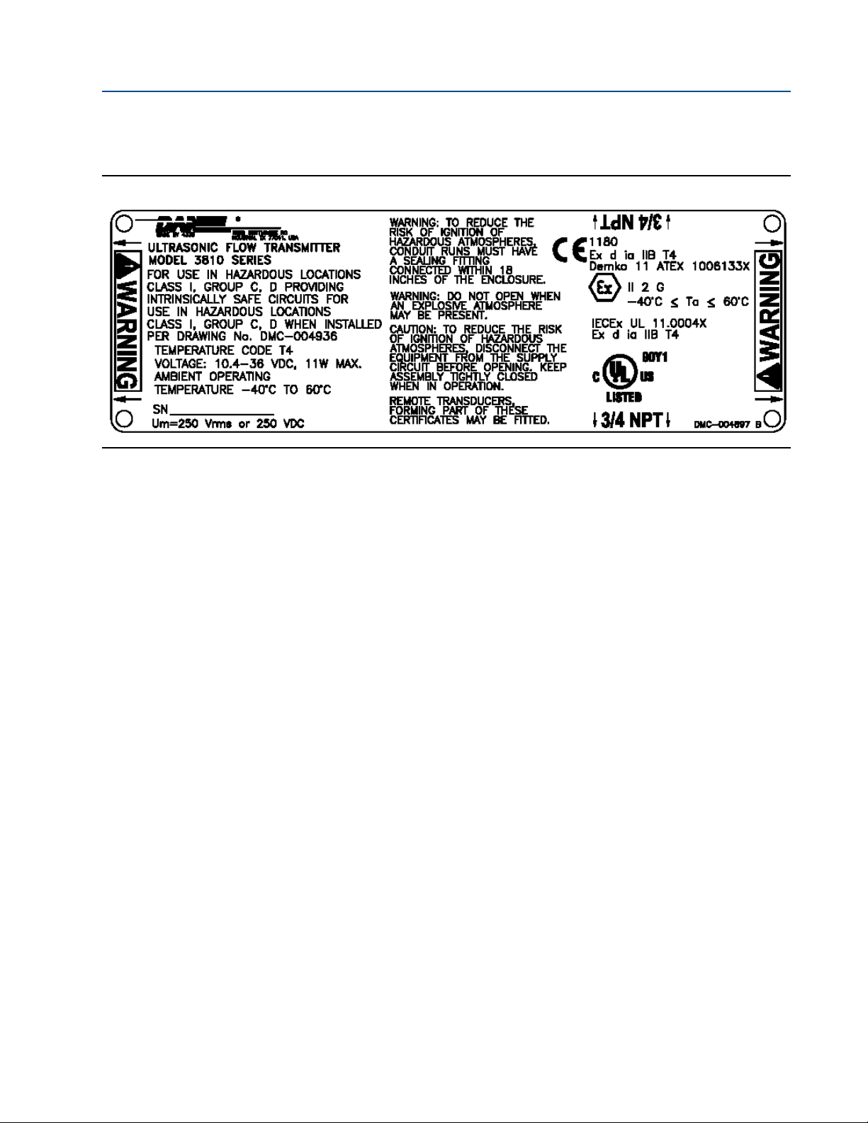
The Daniel 3810 Series Liquid Ultrasonic Meter is approved to the ATEX Directive 94/9/E
Figure 1-3 Daniel 3810 Series Liquid Ultrasonic Meter ATEX approval
1.9 Certifications and approvals
Daniel 3818 LNG Liquid Ultrasonic Flow Meters have electrical, metrology, intrinsic safety and
Pressure Equipment Directive certifications and approvals by the agencies listed below. Refer to
the nameplate tag on the meter body, the wiring diagram (P/N DMC - 004936) in Appendix A
and observe all safety precautions. Daniel 3810 Series Liquid Ultrasonic Flow Meters operate
within the pressure and temperature range of the device (also see Section 1.6 for meter specifications).
Standards
• US
• Canada
• Europe
- Explosive Atmospheres (ATEX)
- International Electro-technical Commission (IECEx)
- Pressure Equipment Directive (PED)
- Electromagnetic Compatibility (EMC)
- International Organization of Legal Metrology (OIML)
12 Certifications and approvals
Page 27
Daniel 3818 LNG Liquid Ultrasonic Meter Installation Manual Section 1: Introduction
Changes or modifications not expressly approved by the party responsible for compliance
could void the user's authority to operate the equipment.
3-9000-771 Rev A May 2012
Approval Agencies
• UL
• ULC
• DEMKO
• NMi
• INMETRO
• NEPSI
• GOSTR
IMPORTANT
Please consult Daniel for a complete metrology approvals list.
1.10 FCC compliance
This equipment has been tested and found to comply with the limits for a Class A digital device,
pursuant to Part 15 of the FCC Rules. These limits are designed to provide reasonable protection
against harmful interference when the equipment is operated in a commercial environment.
This equipment generates, uses, and can radiate radio frequency energy and, if not installed and
used in accordance with the instruction manual, may cause harmful interference to radio communications. Operation of this equipment in a residential area is likely to cause harmful
interference in which case the user will be required to correct the interference at his own
expense.
FCC compliance 13
Page 28

Section 1: Introduction Daniel 3818 LNG Liquid Ultrasonic Meter Installation Manual
May 2012 3-9000-771 Rev A
14 FCC compliance
Page 29
Daniel 3818 LNG Liquid Ultrasonic Meter Installation Manual Section 2: Mechanical installation
SURFACE TEMPERATURE HAZARD
The meter body and piping may be extremely cold.
Wear appropriate personal protective equipment when coming in contact with the meter. Failure to do so may
result in injury.
TRIPPING HAZARD
Clear all obstacles or obstructions from the work area when transporting, installing or removing the
meter.
Failure to clear the work area may cause injury to personnel.
CUTTING HAZARD
Sharp edges may be present on the meter.
Wear appropriate personal protective equipment when working on the meter. Failure to do so may cause
serious injury.
TRANSPORTATION HAZARD
When moving the meter, do not insert the forks of a forklift into the bore.
inserting the forks may cause the meter to become unstable, resulting in injury or damage to the bore and
sealing face.
3-9000-771Rev A May 2012
Section 2: Mechanical installation
2.1 Meter piping, lifting and mounting
Refer to the following sections for piping recommendations, lifting with hoist rings and slings,
mounting in cooled pipelines and safety warnings and precautions.
Section 2: Mechanical installation 15
Page 30
Section 2: Mechanical installation Daniel 3818 LNG Liquid Ultrasonic Meter Installation Manual
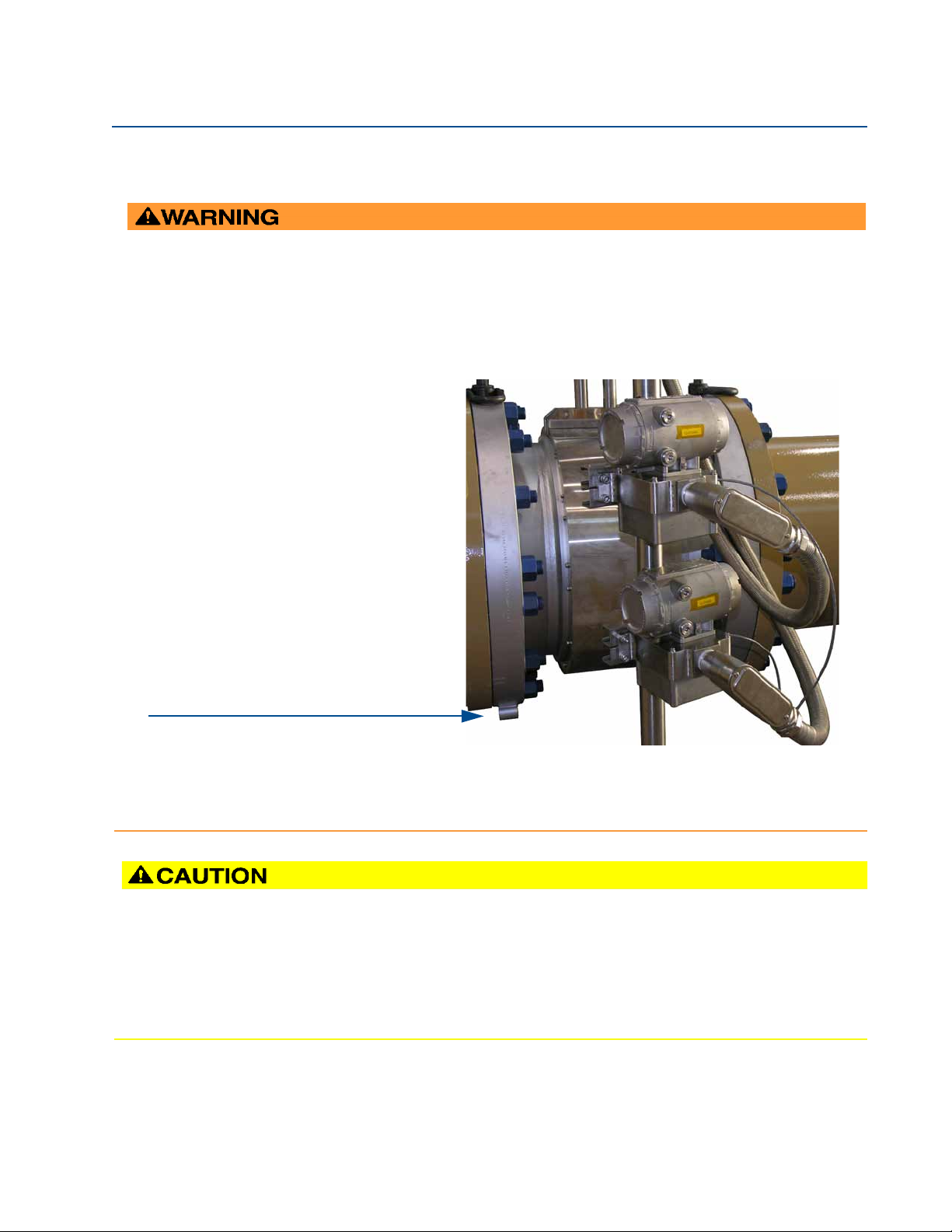
CRUSHING HAZARD
Do not remove flange stabilizers.
Attempting to do so may allow the meter to roll, resulting in serious injury or equipment damage.
A.
A. Flange stabilizers
ESCAPING FLUIDS HAZARD
The purchaser of the meter is responsible for the selection of Daniel components/seals and materials
compatible with the chemical properties of the measurement fluid.
Failure to select suitable meter components/seals may cause escaping fluids, resulting in injury or equipment
damage.
.
May 2012 3-9000-771 Rev A
16 Meter piping, lifting and mounting
Page 31

Daniel 3818 LNG Liquid Ultrasonic Meter Installation Manual Section 2: Mechanical installation
C. Cover/Bracket for 3818 base enclosure
A.
C.
F.
D. Intrinsically-safe base enclosures includes Acquisition Module
D.
E. Flexible and rigid conduit for transducer cables
B.
F. Meter body with band shroud covering transducers, cables and insulation
A. LB Conduit outlet body assembly
B. Explosion-proof co-located transmitter enclosures
(CPU Module, Power Supply, I.S. Barrier Board, Backplane Board)
E.
3-9000-771Rev A May 2012
2.2 Meter components
Daniel 3818 LNG Liquid Ultrasonic Flow Meters are assembled, configured, and tested at the
factory. The meter components include the remote mount co-located Transmitter Electronics
Enclosures, the Base Electronics Enclosure and the Meter Body with transducer assemblies.
Figure 2-1 Daniel 3818 Liquid Ultrasonic Flow Meter assembly
Meter components 17
Page 32

Section 2: Mechanical installation Daniel 3818 LNG Liquid Ultrasonic Meter Installation Manual
EXPLOSION OR FIRE HAZARD
Read and follow the instructions below:
• Conduit runs must have a sealing fitting within 457mm (18 inches) of the enclosure to reduce the
risk of an explosion or a fire.
• During operation, keep covers tightly closed. DO NOT open the transmitter electronics
enclosures when an explosive atmosphere may be present.
• During equipment maintenance, disconnect power before opening the transmitter electronics
enclosures. Clean cover joints before replacing.
• DO NOT substitute meter components. Substituting components may compromise the intrinsic
safety of the device.
Failure to follow these safety instructions may result in severe injury to personnel or cause damage to the
equipment.
For optimal flow measurement conditions, Daniel suggests the piping configurations below. Regardless of the
configuration selected, the user agrees to accept full responsibility for the site piping design and installation.
May 2012 3-9000-771 Rev A
2.3 Piping recommendations
Recommendations for best measurement results:
• Honed or un-honed meter tube(s)
• Flow direction (unidirectional or bidirectional)
• Correct meter size selection - too low may cause poor flow stability (thermal convection)
or too fast may cause erosion problems and resonance, cracks or failure of probes or
thermowells (approximately .6 to 12 m/sec or 2 to 40 ft/sec).
• Space availability for meter lengths (to allow inlet piping customization)
• Concentric alignment pins or flange concentricity technique considerations
18 Piping recommendations
Page 33

Daniel 3818 LNG Liquid Ultrasonic Meter Installation Manual Section 2: Mechanical installation
Flow conditioners are NOT recommended for 3818 LNG Liquid Ultrasonic Flow Meters based
on low flow rate conditions in liquefied natural gas applications.
important
3-9000-771Rev A May 2012
Figure 2-2 Piping recommendations unidirectional flow
Figure 2-3 Piping recommendations bidirectional flow
All pipe lengths are minimum:
• D = Nominal pipe size in inches (i.e. 6" pipe size; 10 D = 60 in)
• P = Pressure measurement location
• T = Temperature measurement location
Piping recommendations 19
Page 34

Section 2: Mechanical installation Daniel 3818 LNG Liquid Ultrasonic Meter Installation Manual
FAULTY METER INSTALLATION
Correctly install the equipment.
If meter bodies are mounted or oriented differently than specified above, debris may collect
in the transducer ports which could adversely affect the transducer signals, or cause
equipment damage.
May 2012 3-9000-771 Rev A
• The bore of the mating piping should be within 1% of the meter inside diameter.
• The meter is provided with dowel pins to align the meter body bore with the bore of the
mating piping.
• The Daniel 3818 LNG Liquid Ultrasonic Flow Meter should be mounted in horizontal
piping with the chord paths horizontal
• The dual transmitter electronics assemblies are remote mounted.
• The mating piping should include temperature and pressure measurement connections
located a minimum of two nominal pipe diameters length down stream of the meter, or
per API MPMS 5.8.
20 Piping recommendations
Page 35

Daniel 3818 LNG Liquid Ultrasonic Meter Installation Manual Section 2: Mechanical installation
LEAKAGE OR PRESSURE CONTAINING PARTS FAILURE
Use precautions to eliminate hazards to personnel in the event of leakage or failure of
the liquid ultrasonic meter pressure containing parts or failure of the test equipment
and to prevent over-pressurization during the test procedure.
Failure to do so may result in injury to personnel or cause damage to the equipment.
3-9000-771Rev A May 2012
2.4 Field hydrostatic pressure testing
The Daniel 3818 LNG Liquid Ultrasonic Flow Meter can be hydro-tested without any special
preparations. The transducers are not exposed to the process pressure and can remain installed
in the meter.
The liquid ultrasonic meter pressure containing parts include but are not limited to the
transducer housings. These pressure containing parts are pressure tested while attached to the
meter body as a completed ultrasonic meter assembly.
The hydrostatic test is verification of the pressure containing capability of the liquid ultrasonic
meter pressure containing parts and the seals that seal them. Perform a visual inspection of the
meter and visually inspect the meter and leak test the flanges.
Field hydrostatic pressure testing 21
Page 36

Section 2: Mechanical installation Daniel 3818 LNG Liquid Ultrasonic Meter Installation Manual
HOISTING AND LIFTING HAZARD
Lifting a Daniel Ultrasonic Meter with Other Equipment
The following lifting instructions are for installation and removal of the Daniel 3818 LNG
Liquid Ultrasonic Meter ONLY. The instructions below do not address lifting the Daniel
ultrasonic meter while it is attached, bolted, or welded to meter tubes, piping, or other
fittings.
Using these instructions to maneuver the Daniel Ultrasonic Meter while it is still attached,
bolted, or welded to a meter tube, piping, or other fitting may result in equipment damage,
serious injury, or death.
The operator must refer to their company's hoisting and rigging standards, or the
"DOE-STD-1090-2004 Hoisting and Rigging" standard if such company standards do not exist,
for lifting and maneuvering any assembled meter tube and associated piping.
CRUSHING HAZARD
During meter installation or removal, always place the unit on a stable platform or
surface that supports its assembled weight. Provide support for the dual transmitter
electronics assemblies during installation and removal.
Failure to do so could allow the meter to roll and the electrical wiring conduit connections to
be severed, resulting in serious injury or equipment damage.
Prior to lifting the unit, refer to the Daniel 3818 LNG Liquid Ultrasonic Flow Meter nameplate or
outline dimensional (general arrangement) drawing for the assembled weight.
May 2012 3-9000-771 Rev A
2.5 Meter safety for hoist rings and lifting slings
A Daniel Liquid Ultrasonic Flow Meter can be safely lifted and maneuvered into and out of a
meter run for installation or service by obeying the following instructions.
22 Meter safety for hoist rings and lifting slings
Page 37

Daniel 3818 LNG Liquid Ultrasonic Meter Installation Manual Section 2: Mechanical installation
A. Plug Bolt
B. Flat Counterbore Surface
A.
B.
3-9000-771Rev A May 2012
When lifting an ultrasonic meter by itself, Daniel recommends two methods. These methods
are:
• Using appropriately rated Safety Engineered Swivel Hoist Rings installed in the Daniel
Ultrasonic Meter end flanges.
• Using appropriately rated lifting slings positioned at designated areas of the Daniel
Ultrasonic Meter.
Both methods must be used in conjunction with all appropriate company hoisting and rigging
standards or the DOE-STD-1090-2004 HOISTING AND RIGGING
standards do not exist. Refer to the following sections for more information on these two
methods.
standard if such company
2.5.1 Use of appropriate safety engineered swivel hoist rings in meter end flanges
Daniel Ultrasonic Meters come equipped with a tapped hole located on the top of each meter
body end flange. A flat machined surface surrounds each tapped hole. This feature provides
complete surface contact ONLY between the meter flange and an OSHA compliant Safety
Engineered Swivel Hoist Ring as shown in Figure 2-5.
Operators SHALL NOT use eye bolts (see Figure 2-5) in the Daniel 3818 LNG Liquid Ultrasonic
Meter flange tapped holes to aid in lifting or maneuvering the unit.
Operators SHALL NOT use other hoist rings that do not fully seat flush with the counter bore on
the top of the meter flanges.
Figure 2-4 Meter end flange with tapped flat-counterbore hole for hoist ring
Use of appropriate safety engineered swivel hoist rings in meter end flanges 23
Page 38

Section 2: Mechanical installation Daniel 3818 LNG Liquid Ultrasonic Meter Installation Manual
Eye bolt
Safety engineered swivel hoist ring
May 2012 3-9000-771 Rev A
Figure 2-5 Safety approved hoist ring and non-compliant eye bolt
Safety precautions using safety engineered swivel hoist rings
Read and follow the safety precautions listed below:
1. Meters must only be lifted by personnel properly trained in the safe practices of rigging
and lifting.
2. Remove the plug bolts installed in the tapped holes on the top of the flanges. Do not
discard the bolts as they must be reinstalled once the lifting operation is complete to
prevent corrosion of the tapped holes.
3. Make sure the tapped holes on the meter are clean and free of debris before installing
the hoist rings.
4. Use only the safety engineered swivel hoist rings that are rated for lifting the meter. Do
not use any other type of hoist rings with the same screw size or heavy duty hoist rings.
The meter tapping and counter bore size are suitable only for the hoist rings specified
by Daniel.
5. When installing a hoist ring, make sure the base surface of the hoist ring fully contacts
the machined flat surface of the tapped hole. If the t wo surfaces do not come in contact
then the hoist ring will not hold its full rated load. Torque the hoist ring attachment
bolts to the limit indicated on the hoist rings.
6. After installation of the hoist rings, always check that the ring rotates and pivots freely
in all directions.
7. NEVER attempt to lift the meter using only one hoist ring.
24 Use of appropriate safety engineered swivel hoist rings in meter end flanges
Page 39

Daniel 3818 LNG Liquid Ultrasonic Meter Installation Manual Section 2: Mechanical installation
3-9000-771Rev A May 2012
8. Always use separate slings to each hoist ring. NEVER reeve one sling through both hoist
rings. The slings must be of equal length. Each sling must have a load rating that equals
or exceeds the hoist ring load rating. The angle between the two slings going to the
hoist rings must never exceed 90 degrees or the load rating of the hoist rings will be
exceeded.
Figure 2-6 90 Degree angle between slings
Use of appropriate safety engineered swivel hoist rings in meter end flanges 25
Page 40

Section 2: Mechanical installation Daniel 3818 LNG Liquid Ultrasonic Meter Installation Manual
May 2012 3-9000-771 Rev A
9. Always provide support for the dual transmitter electronics during the lifting
operation. Lifting the meter without supporting the electronics, may cause the
electronics to fall and cause personal injury or equipment damage.
NEVER allow the slings connected to the hoist rings contact the LB conduit bodies.
Damage to the enclosure may occur. Once the lifting operation is complete, attach and
secure the electronics to the pipe stand or other rigid structure with the mounting
bracket and bolts.
Figure 2-7 Incorrect sling attachment
26 Use of appropriate safety engineered swivel hoist rings in meter end flanges
Page 41

Daniel 3818 LNG Liquid Ultrasonic Meter Installation Manual Section 2: Mechanical installation
3-9000-771Rev A May 2012
10. NEVER apply shock loads to the meter. Always lift the meter gradually. If shock loading
ever occurs, the hoist ring must be inspected per manufacturer's recommendations
prior to be placed in any further service. If a proper inspection cannot be performed,
discard the hoist ring.
11. NEVER lift with any device, such as hooks, chains, or cables that could create side pulls
that could damage the ring of the hoist ring.
12. NEVER lift more than the ultrasonic meter assembly including electronics and
transducers with the hoist rings. The only exception is that it is safe to lift the meter
with one ASME B16.5 or ASME B16.47 blind flange bolted to each end flange of the
meter. NEVER use the hoist rings on the meter to lift other components such as meter
tubes, piping or fittings attached to the meter. Doing so will exceed the load rating of
the hoist rings.
13. Remove the hoist rings from the meter after lifting is completed and store them in an
appropriate case or container per their manufacturer's recommendation.
14. Apply heavy lubricant or anti-seize to the threads of the plug bolts and reinstall the plug
bolts to keep the tapped holes free of debris and to prevent corrosion.
How to obtain safety engineered swivel hoist rings
A list of approved manufacturers of safety engineered hoist rings is below:
• American Drill Bushing Company(
• Carr Lane Manufacturing Company (
www.americandrillbushing.com)
www.carrlane.com)
Select an approved supplier from the list below. These vendors can supply the safetyengineered hoist rings. This is not intended to be a complete list.
• Fastenal (
• Reid Supply
www.fastenal.com)
(http://www.reidsupply.com/)
The appropriate hoist rings can also be purchased directly from Daniel. The following table
provides part number for reference:
Table 2-1 Hoist ring part number
Daniel part
number
1-504-90-094 1"-8UNC, 10000 lb. 23105 CL-10000-SHR-1
1. Note: The part number only includes one hoist ring. Two hoist rings are required for the meter.
1
Hoist ring thread size &
load rating
1
American Drill
Bushing Co. P/N
1
Carr Lane Manufacturing Co. P/N
What size safety engineered swivel hoist ring do you need?
1
To determine the size of the hoist rings required for your meter, use the table below for the 3818
LNG Liquid Ultrasonic Meter. The part number shown in Table 2-2 is appropriately rated for the
ANSI rating of your meter.
Table 2-2 Hoist ring table for Daniel 3818 LNG Liquid Ultrasonic Flow Meters
ANSI 300 Daniel Part Number
30” 1-504-90-094
Use of appropriate safety engineered swivel hoist rings in meter end flanges 27
Page 42

Section 2: Mechanical installation Daniel 3818 LNG Liquid Ultrasonic Meter Installation Manual
May 2012 3-9000-771 Rev A
2.5.2 Appropriately rated lifting slings
The following instructions are intended to provide general guidelines for proper lifting slings of
the Daniel 3818 Ultrasonic meter by itself. These instructions are intended to be followed in
addition to your company's standards or the DOE-STD-1090-2004 Hoisting and Rigging
standard if such company standards do not exist.
Safety precautions using appropriate rated lifting slings
1. Only personnel properly trained in the safe practices of rigging and lifting are allowed
to perform lifting operations.
2. NEVER attempt to lift the meter by wrapping slings around the electronics enclosures
or the conduit piping.
28 Appropriately rated lifting slings
Page 43

Daniel 3818 LNG Liquid Ultrasonic Meter Installation Manual Section 2: Mechanical installation
3-9000-771Rev A May 2012
3. NEVER attempt to lift the meter using only one sling around the meter. Always use two
slings wrapped around each end of the body as shown below. A choker style sling is
recommended.
Figure 2-8 Correct sling attachment with spreader bar
4. Visually inspect the slings prior to use for any signs of abrasion or other damage. Refer
to the sling manufacturer's procedures for proper inspection of the particular sling you
are using.
5. Only use slings with ratings that exceed the weight to be lifted. Reference your
company's standards for safety factors that must be included when calculating the load
rating.
6. Provide support for the transmitter electronics assemblies during lifting operations.
7. Once the lifting operation is complete, attach and secure the electronics to the pipe
stand or other rigid structure using the mounting bracket bolts. Lifting the meter
without supporting the transmitter enclosures, may cause the electronics to fall and
cause personal injury or electronics damage.
Appropriately rated lifting slings 29
Page 44

Section 2: Mechanical installation Daniel 3818 LNG Liquid Ultrasonic Meter Installation Manual
May 2012 3-9000-771 Rev A
Figure 2-9 Incorrect sling attachment
8. NEVER apply shock loads to the meter. Always lift the meter gradually. If shock loading
ever occurs, the slings must be inspected per manufacturer's procedures prior to being
placed in any further service.
30 Appropriately rated lifting slings
Page 45

Daniel 3818 LNG Liquid Ultrasonic Meter Installation Manual Section 2: Mechanical installation
install sufficient insulation over the meter assembly, shrouds and adjoining upstream and
downstream piping. The thickness and type of insulation used is to be determined by the
customer for the ambient conditions. For accurate flow meter operation the liquefied natural
gas fluid flowing within the meter must be liquid without any gas pockets or bubbles. The
insulation installed must be adequate to insure bubble free liquid flow is achieved at all flow
rates and ambient conditions.
3-9000-771Rev A May 2012
2.6 Mounting requirements in Liquefied Natural Gas pipelines
The ambient operating temperature of the Daniel 3818 LNG Liquid Ultrasonic Flow Meter
o
electronics (i.e. Flameproof enclosure and Intrinsically safe base enclosure) is -40
o
C (+140o F). The 3818 LNG Liquid Ultrasonic Flow meter electronics are remote mounted
+60
on a vertical or horizontal two (2) inch pipe which is securely installed and rigid.
C (-40o F) to
Mounting requirements in Liquefied Natural Gas pipelines 31
Page 46

Section 2: Mechanical installation Daniel 3818 LNG Liquid Ultrasonic Meter Installation Manual
A.
D.
C.
A.Rigid and flexible conduit for routing cables from transducers to Acquisition Module
B.Pipe strut clamp and channel assembly securing electronics to 2 inch vertical pole or horizontal rail
B.
C. Acquisition Module to transducer connections
E.
D. 3818 LNG meter body with shrouds
E. Customer supplied vertical pole (2 inch pipe). May be horizontal rail. Must be securely installed and rigid.
May 2012 3-9000-771 Rev A
Transducer cables (P/N 1-504-90-128, 15 ft. long maximum) are connected to the Daniel 3818
LNG Liquid Ultrasonic Flow Meter electronics and then routed to the transducers installed in the
meter body.
Figure 2-10 Transducer cabling conduit
32 Mounting requirements in Liquefied Natural Gas pipelines
Page 47

Daniel 3818 LNG Liquid Ultrasonic Meter Installation Manual Section 2: Mechanical installation
SURFACE TEMPERATURE HAZARD.
The meter body and piping may be extremely cold.
Wear appropriate personal protective equipment when coming in contact with the meter.
Failure to do so may result in injury.
3-9000-771Rev A May 2012
The process temperature must not exceed the operating temperature range of the LT-07
o
transducers. These transducers have an operating range from -196
o
(+140
F).
C (-321o F) to +60o C
Mounting requirements in Liquefied Natural Gas pipelines 33
Page 48

Section 2: Mechanical installation Daniel 3818 LNG Liquid Ultrasonic Meter Installation Manual
May 2012 3-9000-771 Rev A
34 Mounting requirements in Liquefied Natural Gas pipelines
Page 49

Daniel 3818 LNG Liquid Ultrasonic Meter Installation Manual Section 3: Electrical installation
3-9000-771 Rev A May 2012
Section 3: Electrical installation
3.1 Cable length TTL mode
The maximum cable length is 2000 feet when the “TTL” mode is selected.
3.2 Cable length Open Collector mode
For the “open collector” mode, the maximum cable length depends on the cable parameters,
pull-up resistance used, the maximum frequency to output, and frequency input parameters
being driven. The following table provides estimated cable lengths for different pull-up resistor
values and different Max Frequency settings in the meter using the following cable parameters.
The table also provides an estimated cable voltage drop which indicates how much voltage will
be across the cabling and effectively indicates to what voltage level the frequency input can be
pulled down to by the frequency output.
If the voltage drop is higher than the voltage required for the frequency input to see a low state,
then the configuration will most likely not work for your system. Performance of frequency
outputs will vary from this table with setup and frequency input being driven.
Table 3-1 Configurations for open collector frequency outputs
Cable
Cable
Length (2 Conductors) Capacitance Resistance Resistance Frequency Current (2 Conductors)
(x1000ft) nF (Hz) (A) VDC
0.5 16.8 10.00 1000 1016.8 5000 0.024 0.397
1 33.6 20.00 1000 1033.6 1000 0.023 0.780
2 67.2 40.00 1000 1067.2 1000 0.022 1.511
4 134.4 80.00 1000 1134.4 1000 0.021 2.843
0.5 16.8 10.00 500 516.8 5000 0.046 0.780
1 33.6 20.00 500 533.6 5000 0.045 1.511
1.7 57.12 34.00 500 557.12 5000 0.043 2.461
6.5 218.4 130.00 500 718.4 1000 0.033 7.296
resistance
The 22 AWG wire characteristics are as follows:
• Capacitance = 20 pF/ft or 20 nF/1000 ft (between two wires)
• Resistance = 0.0168 Ohms/ft or 16.8 Ohms/1000 ft
• Pull-up voltage is 24 VDC
Cable
Pull-up
resistance
Tot a l
Maximum
frequency
Sink
Cable voltage
drop
Section 3: Electrical installation 35
Page 50

Section 3: Electrical installation Daniel 3818 LNG Liquid Ultrasonic Meter Installation Manual
The internal grounding terminal shall be used as the primary equipment ground. The
external terminal is only a supplemental bonding connection where local authorities permit
or require such a connection.
A. Transmitter Electronics Enclosure internal ground lug
A.
May 2012 3-9000-771 Rev A
3.3 Grounding meter electronics
Daniel Liquid Ultrasonic Flow Meter electronics should be internally grounded for intrinsically
safe operations. Connect a wire to the chassis ground lug installed inside the Transmitter
Electronics Enclosure as the primary ground.
Figure 3-1 Internal Transmitter Electronics Enclosure chassis ground
36 Grounding meter electronics
Page 51

Daniel 3818 LNG Liquid Ultrasonic Meter Installation Manual Section 3: Electrical installation
A.
A. External ground lug
3-9000-771 Rev A May 2012
Secondary grounds are located outside of the Transmitter Electronics Enclosure
(see Figure 3-2).
Figure 3-2 External ground lug
Grounding meter electronics 37
Page 52

Section 3: Electrical installation Daniel 3818 LNG Liquid Ultrasonic Meter Installation Manual
HAZARDOUS VOLTAGE
Do not open the Transmitter Electronics Enclosure in a flammable gas area. Disconnect
power before servicing.
Do not disconnect equipment unless power has been removed or the area is known to be a
non-hazardous. Failure to follow these instructions may result in serious injury or death.
EXPLOSION HAZARD
Substitution of components may impair the intrinsic safety and cause ignition of flammable
or combustible atmospheres. Disconnect power before servicing.
Failure to remove power and use Daniel approved components may cause serious injury.
May 2012 3-9000-771 Rev A
3.4 Conduit seals
Daniel 3818 LNG Liquid Ultrasonic Meters require conduit seals for installations in hazardous
environments. Adhere to safety instructions to protect personnel and equipment.
38 Conduit seals
Page 53

Daniel 3818 LNG Liquid Ultrasonic Meter Installation Manual Section 3: Electrical installation
HAZARDOUS VOLTAGE INSIDE
Do not open in flammable gas area. Disconnect all power to the meter.
Failure to follow the instructions in this manual may result in serious injury or death.
3-9000-771 Rev A May 2012
3.4.1 Startup for systems using explosion-proof conduit
1. Assemble conduit to the Transmitter Electronics Enclosure. A conduit seal is required
within 18 inches (457 mm) of the enclosure.
2. Check to make certain that all power to field wiring is turned OFF.
3. Check the serial number tag on top of the Transmitter Electronics Enclosure. Remove
the end cap with the serial tag marked with _H1(nearest its conduit entry) to gain
access to the transmitter electronics.
4. Pull the wires into the enclosure.
5. Complete the field connection wiring according to the system wiring diagram (see
Appendix A).
6. Repeat Step 2 through Step 5 for the Transmitter Electronics Enclosure with the serial
tag marked with _H2.
7. Apply electrical power to the system to ensure the field connections are working
correctly. Replace the end caps and allow the system to run for the time specified by the
customer (usually one week) and an electrician has fully tested the connections. After
the Acceptance Test is witnessed and approved, seal the conduit.
8. Power down the system and apply the sealing compound to the conduit and allow to
set in accordance with manufacturer specifications.
9. If required, install the security latches and wire seals on the Transmitter Electronics
Enclosure end caps (see Section 3.6.8 and see Figure 3-9).
10. If required, install the wire seals through the socket head bolts on the Base Enclosure
(see Section 3.6.8).
11. Connect electrical power to the system.
12. Set or configure the meter using Daniel MeterLink. For additional installation
information refer to the system wiring diagram (see Appendix A), Daniel MeterLink
Quick Start Manual (P/N 3-9000-763). Use the Daniel MeterLink Field Setup Wizard to
complete the configuration. Also see, Section 4.1in this Manual.
Startup for systems using explosion-proof conduit 39
Page 54

Section 3: Electrical installation Daniel 3818 LNG Liquid Ultrasonic Meter Installation Manual
HAZARDOUS VOLTAGE INSIDE
Do not open in flammable gas area. Disconnect all power to the meter.
Failure to follow the instructions in this manual may result in serious injury or death.
May 2012 3-9000-771 Rev A
3.4.2 Startup for systems that use flame-proof cable
1. Check to make certain that all field wiring power is turned OFF.
2. Check the serial number tag on top of the Transmitter Electronics Enclosure. Remove
the end cap with the serial tag marked with _H1(nearest its conduit entry) to gain
access to the transmitter electronics.
3. Install the cable and cable gland.
4. Complete the field connection wiring.
5. Connect a flow computer to the communications line on the Daniel Liquid Ultrasonic
Flow Meter.
6. Repeat Step 2 through Step 5 for the Transmitter Electronics Enclosure with the serial
number tag marked with _H2.
7. Apply electrical power to the system to ensure the field connections are working
correctly. Replace the end caps and allow the system to run for the time specified by
the customer (usually one week) and an electrician has fully tested the connections.
8. If required, install the security latches and wire seals on the Transmitter Electronics
Enclosure end caps (see Section 3.6.8 and Figure 3-9).
9. Install the wire seals through the socket head bolts on the Base Enclosure
(see Section 3.6.8 and Figure 3-10 and the junction box).
10. Make sure the safety latches are installed on the Transmitter Electronics Enclosure.
11. Set or configure the software using Daniel MeterLink. For additional installation
information refer to the system wiring diagram (see Appendix A), Daniel MeterLink
Quick Start Manual (P/N 3-9000-763). Use the Daniel MeterLink Field Setup Wizard to
complete the meter configuration. Also see, Section 4.1in this Manual.
40 Startup for systems that use flame-proof cable
Page 55

Daniel 3818 LNG Liquid Ultrasonic Meter Installation Manual Section 3: Electrical installation
If not using Ethernet, a full duplex serial connection is necessary for Daniel MeterLink to
communicate with a Daniel 3818 Liquid Ultrasonic Meter.
Note:
Daniel recommends running conduit and field wiring to each of the co-located Transmitter
Electronics Enclosures and wiring each of the meters.
3-9000-771 Rev A May 2012
3.5 Wiring and I/O
Daniel MeterLink uses the TCP/IP protocol to communicate with the 3818 LNG Liquid Ultrasonic
Flow Meter electronics instead of Modbus ASCII or RTU. The TCP/IP protocol only works across
either Ethernet, RS-485 full duplex (i.e., 4-wire), or RS-232. Daniel MeterLink can communicate
with multiple meters if they are multi-dropped using 4-wire full duplex RS-485 mode. The meter
electronics is HART capable and provides communication flexibility with Daniel 3818 LNG Liquid
Ultrasonic Flow Meters.
The HART® output provides communication with other field devices (e.g., Field Communicator
and AMS™ Device Manager software) and ultimately, communicates key diagnostic information
through PlantWeb® architecture.
The Daniel 3818 LNG Liquid Ultrasonic Flow Meter has two 3814 electronics enclosures and
auto-detects the protocol used and automatically switches between TCP/IP, Modbus ASCII, and
Modbus RTU so it is not necessary to make any meter configuration changes to change the
protocol.
Two sets of transmitter electronics (co-located) are provided with the Daniel 3818 LNG Liquid
Ultrasonic Flow Meter. The Primary (master) electronics are in the upstream enclosure with the
serial tag marked _H1. The Secondary (slave) electronics are in the downstream enclosure with
the serial tag marked _H2.
Wiring and I/O 41
Page 56

Section 3: Electrical installation Daniel 3818 LNG Liquid Ultrasonic Meter Installation Manual
A.
B.
C.
D.
E.
A. Acquisition/Measurement mode
B. Power
C. RX (RS-485/RS-232) - receiving data
D. LED 4 - not used
E. LED 5 - not used
F. TX (RS-485/RS-232) - transmitting data
F.
G.
G. Link (Eth1 Link) - user Ethernet connection
May 2012 3-9000-771 Rev A
3.5.1 CPU Module labeling and LED indicators
The meter’s metrology mode and the status of the data transfer from the Acquisition Module to
the CPU Module is indicated via light-emitting diode (LED) status indicators. The Write PROT.
switch prevents overwriting the meter’s configuration,
Figure 3-3 CPU Module labeling and LED indicators
42 CPU Module labeling and LED indicators
Page 57

Daniel 3818 LNG Liquid Ultrasonic Meter Installation Manual Section 3: Electrical installation
3-9000-771 Rev A May 2012
Table 3-2 CPU Module labeling and LED functions
CPU Module labeling
and LED functions
WRITE PROT.
Function Switch position indicator or LED
• Write-protect mode - with switch in the ON
position (default setting) protects configuration
and firmware overwrites.
• To write configuration changes or download
firmware to the meter change the switch to the
OFF position
DHCP
• Dynamic Host Protocol Server - enables you to
communicate with a Daniel meter that is not
connected to a network.
• When the CPU Module switch is in the ON
position, the meter is enabled to act as a DHCP
server for a single DHCP client connected to the
Ethernet port using a crossover cable. This should
be used for peer to peer connections only.
• When the connection is made, select to use the
Meter Name in the meter instead of the Meter
Directory Name in order to keep all log files and
configurations separate from each meter.
PORT A
• PORT A override - RS-232 serves as an override
during meter commissioning to establish communications and in the event the user cannot
communicate with the meter due to an inadvertent communication configuration change. The
override period is for two minutes
• Supports:
- auto-detected ASCII (Start bit 1, Data Bit 7,
Parity Odd/Even, Stop Bit 1)
- RTU (Start Bit 1, Data Bit 8, Parity none, Stop
Bit 1).
- Modbus protocols
• RS-232 Baud rate=19,200
• Modbus ID=32
MEAS System color indicates metrology mode
• Acquisition mode
• Measurement mode
PWR
LED 4
LED 5
RX
TX
LINK
• 3.3V Power Indicator • Solid Green
• Not used
• Not used
• RX signal (Port A for RS485 or RS232
communication) receiving data
• TX signal (Port A for RS485 or RS232
communication) transmitting data
• ETH1Link user Ethernet connection • Solid green
Switch position
• ON - (default setting) enables write-
protection of the configuration and
firmware
• OFF - enables writing configuration
changes or downloading firmware
Switch position
• ON - the meter is enabled to act as a
DHCP server for a single DHCP client
• OFF - disables the DHCP server
Switch position
• ON - enables RS-232 PORT A override
• OFF - (default setting) disables
RS-232 PORT A
LED status
• Red flashing LED
• Solid red the Acquisition Module not
communicating with the CPU Module
• Green flashing LED
• Flashing green (when receiving data)
• Flashing green (when transmitting
data)
CPU Module labeling and LED indicators 43
Page 58

Section 3: Electrical installation Daniel 3818 LNG Liquid Ultrasonic Meter Installation Manual
RESTRICT ETHERNET AND SERIAL CONNECTIVITY USAGE
Failure to restrict Ethernet and communication access to the Daniel 3818 LNG Liquid
Ultrasonic Flow Meter can result in, among other things, unauthorized access, system
corruption, and/or data loss.
User is responsible for ensuring that physical access and Ethernet or electronic access to the
Daniel 3818 LNG Liquid Ultrasonic Flow Meter is appropriately controlled and any necessary
security precautions, such as, establishing a firewall, setting password permissions and/or
implementing security levels.
RX+
TX+
TX-
RX-
May 2012 3-9000-771 Rev A
Ethernet communications
The Ethernet port IP address, subnet mask, and gateway address are software-configurable. In
addition, a meter can be configured to act as a DHCP (Dynamic Host Configuration Protocol)
server to assign an IP address to a PC or laptop running Daniel MeterLink. The DHCP server
facility is not intended to act as a general purpose DHCP server for a wider network. To this end,
no user control is provided over the class or range of IP addresses the unit provides. A standard
twisted pair (Cat-5) cable should be used for Ethernet wiring.
It is strongly recommended that the meter be configured using an independent (off-network)
single host. After configuration of the Daniel 3818 LNG Liquid Ultrasonic Flow Meter, the DHCP
option must be turned off if used on a LAN/WAN.
Use ethernet cable (Daniel P/N 3-3400-079) to connect the PC to the meter.
Table 3-3 Ethernet cable to PC communication
Ethernet communication
Wire color CPU
White w/Orange Stripe TX+
Orange w/White Stripe TX -
White w/Green Stripe RX+
Green w/White Stripe RX -
44 CPU Module labeling and LED indicators
A DIN 41612 48-pin connector is the interface from the CPU Module to the Backplane Board
(male end located on the back of the Backplane Board).
Page 59

Daniel 3818 LNG Liquid Ultrasonic Meter Installation Manual Section 3: Electrical installation
3-9000-771 Rev A May 2012
Serial connections
Use serial cable (Daniel P/N 3-2500-401) to connect to a PC running Daniel MeterLink. The cable
is designed for RS-232 communications which is the serial Port A default configuration (see
Appendix A field wiring diagram, Daniel Drawing DMC-004936). The DB-9 end of the cable plugs
directly into the PC running Daniel MeterLink. The three wires on the other end of the cable
connect to the CPU Module. The RED wire goes to RX, the WHITE wire goes to TX, and the
BLACK wire goes to COM for the RS-485/RS-232 treenails (Table 3-4 for Port A wiring).
When Beldon wire No. 9940 or equivalent is used, the maximum cable length for RS-232
communications at 9600 bps is 88.3 meters (250 ft.) and the maximum cable length for RS-485
communication at 57600 bps is 600 meters (1970 ft.).
Port A supports a special override mode which forces the port to use known communication
values (19200 baud, address 32, RS-232). Note that the protocol is auto-detected. This mode is
expected to be used during meter commissioning (to establish initial communication) and in
the event that the user cannot communicate with the meter (possibly due to an inadvertent
communication configuration change). Alternately, when using Daniel MeterLink™ with an
Ethernet port, use Ethernet cable (Daniel P/N 3-3400-079) to connect the PC.
Table 3-4 Serial Port A parameters
Port/Communication Description Common features
Port A (Standard)
• RS-232
• RS-485 Half Duplex
• RS-485 Full Duplex
Ethernet
• Typically used for general communications with
a flow computer, RTU (Modbus slave) and
radios.
• Special override mode to force port configura-
tion to known settings.
• Supports RTS/CTS handshaking with software-
configurable RTS on/off delay times.
• Factory default is RS-232, Address 32, 19200
baud.
• Preferred port for diagnostic communication
via Daniel MeterLink
• 10 Mbps/100 Mbps
• Communications via Daniel MeterLink
using RS-232 or RS-485 Full Duplex
• Software configurable Modbus
Address (1-247)
• Auto-detects TCP/IP and ASCII or RTU
Protocol
-
ASCII Protocol:
Start Bits = 1, Data Bits=7
- Parity: odd or even 1, Stop Bits = 1
- Baud Rates: 1200, 2400, 9600,
19200, 38400, 57600, 115000 bps
- RTU Protocol:
Start Bits = 1, Data Bits=8
- Parity: none, Stop Bits = 11
Baud Rates: 1200, 2400, 9600,
-
19200, 38400, 57600, 115000 bps
• Modbus TCP/IP
1
1
1
1. Denotes auto-detected protocols
CPU Module labeling and LED indicators 45
Page 60

Section 3: Electrical installation Daniel 3818 LNG Liquid Ultrasonic Meter Installation Manual
If not using Ethernet, a full duplex serial connection is necessary for Daniel MeterLink to
communicate with a Daniel 3814 Liquid Ultrasonic Flow Meter.
RX
TX
COM
DB-9 Connector Female
May 2012 3-9000-771 Rev A
.
Figure 3-4 PC to meter serial connection wiring
46 CPU Module labeling and LED indicators
Page 61

Daniel 3818 LNG Liquid Ultrasonic Meter Installation Manual Section 3: Electrical installation
A.
B.
C.
D.
A. Frequency/Digital Output 2
B. Frequency/Digital Output 3
C. Analog Output(2) 4-20mA output
D. Analog Input - temperature and pressure connections
3-9000-771 Rev A May 2012
3.6 Daniel Ultrasonic Meters I/O connections
The 3818 LNG Liquid Ultrasonic Flow Meter provides I/O connections on the CPU Module.
Figure 3-5 CPU Module I/O connections
Daniel Ultrasonic Meters I/O connections 47
Page 62

Section 3: Electrical installation Daniel 3818 LNG Liquid Ultrasonic Meter Installation Manual
May 2012 3-9000-771 Rev A
3.6.1 Frequency/Digital outputs
The meter has three user-configurable selections for configuring either a Frequency output or
Digital output (FODO).
• FODO1 (four possible parameter configurations)
• FODO2 (eight possible parameter configurations)
• FODO3 (eight possible parameter configurations)
Frequency or Digital Outputs (FODO 1) source
• FO1A, DO1A, FO1B, DO1B
• Frequency output 1A is based on frequency content (Actual - Uncorrected Flow Rate)
• Frequency output 1B is based on frequency content and Frequency 1 B Phase
• Digital output 1A is based on Digital output1A content (Frequency1A Validity and Flow
Direction)
Frequency or Digital Outputs (FODO 2) source
• FO1A, DO1A, FO1B, DO1B, FO2A, DO2A, FO2B, DO2B
• Frequency output 1A is based on frequency content (Actual - Uncorrected Flow Rate)
• Frequency output 1B is based on frequency content and Frequency 1B Phase
• Frequency output 2A is based on frequency content (Actual - Uncorrected Flow Rate)
• Frequency output 2B is based on frequency content and Frequency 2B Phase
• Digital output 1A is based on Digital output1A content (Frequency 1A Validity and Flow
Direction)
• Digital output 2A is based on Digital output2A content (Frequency 1A Validity and Flow
Direction)
• Digital output 2A is based on Digital output 2A content (Frequency 2A Validity and Flow
Direction)
• Digital output 2B is based on Digital output 2B content (Frequency 2B Validity and Flow
Direction)
48 Frequency/Digital outputs
Page 63

Daniel 3818 LNG Liquid Ultrasonic Meter Installation Manual Section 3: Electrical installation
3-9000-771 Rev A May 2012
Frequency or Digital Outputs (FODO 3) source
• FO1A, DO1A, FO1B, DO1B, FO2A, DO2A, FO2B, DO2B
• FO1A, DO1A, FO1B, DO1B, FO2A, DO2A, FO2B, DO2B
• Frequency output 1A is based on frequency content (Actual - Uncorrected Flow Rate)
• Frequency output 1B is based on frequency content and Frequency 1B Phase
• Frequency output 2A is based on frequency content (Actual - Uncorrected Flow Rate)
• Frequency output 2B is based on frequency content and Frequency 2B Phase
• Digital output 1A is based on Digital output1A content (Frequency 1A Validity and Flow
Direction)
• Digital output 2A is based on Digital output2A content (Frequency 1A Validity and Flow
Direction)
• Digital output 2A is based on Digital output 2A content (Frequency 2A Validity and Flow
Direction)
• Digital output 2B is based on Digital output 2B content (Frequency 2B Validity and Flow
Direction)
Mode options
• Open Collector (requires external excitation supply voltage and pull-up resistor)
• TTL (internally powered by the meter 0-5 VDC signal)
Channel B Phase options:
• Lag forward, Lead reverse (Phase B lags Phase A while reporting forward flow, leads Phase
A while reporting reverse flow)
• Lead forward, Lag reverse (Phase B leads Phase A while reporting forward flow, lags Phase
A while reporting reverse flow)
Phase A and Phase B output (based on flow direction)
• Reverse flow - output only reports flow in the reverse direction. For frequency outputs,
Phase B of the output is 90 degrees out of phase with Phase A.
• Forward flow - output only reports flow in the forward direction. For frequency outputs,
Phase B of the output is 90 degrees out of phase with Phase A.
• Absolute - output reports flow in both directions. For frequency outputs, Phase B of the
output is 90 degrees out of phase with Phase A.
• Bidirectional - output reports flow on Phase A only in the forward direction and on Phase
B only in the reverse direction.
Maximum frequency for the frequency outputs
• 1000Hz
• 5000Hz
Frequency/Digital outputs 49
Page 64

Section 3: Electrical installation Daniel 3818 LNG Liquid Ultrasonic Meter Installation Manual
FODO1
FODO2
FODO3
FO1A
FO1B
DO1A
DO2B
FO2A
FO2B
DO2A
DO2B
May 2012 3-9000-771 Rev A
Table 3-5 Frequency/Digital Outputs possible configurations
Frequency/Digital output Source configuration
Frequency /Digital Output 1
1
• Frequency output 1A
• Frequency output 1B
• Digital output 1A
• Digital output 1B
Frequency /Digital Output 2
2
• Frequency output 1A
• Frequency output 1B
or
• Digital output 1A
• Digital output 1B
Frequency /Digital Output 3
2
• Frequency output 2A
• Frequency output 2B
• Digital output 2A
• Digital output 2B
1. Solid blue line denotes valid selection for Frequency/Digital Output 1.
2. Black dashed -line denotes valid selections for Frequency/Digital Output 2 and Frequency/
Digital Output 3.
50 Frequency/Digital outputs
Page 65

Daniel 3818 LNG Liquid Ultrasonic Meter Installation Manual Section 3: Electrical installation
A.
A. FODO1 and Digital input1 - shared common ground (Group 1)
B. FODO2 and FODO3 - shared common ground (Group 2)
B.
3-9000-771 Rev A May 2012
Output for FODO1 and Digital Output1 (Group 1 on the CPU Module) share a common ground
and have 50V isolation. FODO2 and FODO3 (Group 2 on the CPU Module) share a common
ground and have 50V isolation. This allows an output to be connected to a different flow
computer. The outputs are opto-isolated from the CPU Module and have a withstand voltage of
at least 500V rms dielectric.
Figure 3-6 CPU Module - Frequency/Digital inputs common ground
Frequency/Digital outputs 51
Page 66

Section 3: Electrical installation Daniel 3818 LNG Liquid Ultrasonic Meter Installation Manual
May 2012 3-9000-771 Rev A
3.6.2 Analog input settings
The 3818 LNG Liquid Ultrasonic Flow Meter has the capability to sample analog temperature
(Analog Input 1) and pressure (Analog Input 2) with 4-20 mA signals. These analog input signals
are configured to sink. The two independent analog input circuits are configured for
conventional 4-20 mA service. Also, 24VDC isolated power supply connection is provided for an
external power source. Refer to the Field wiring diagram DMC-004936 in Appendix A.
3.6.3 Analog output settings
The 3818 LNG Liquid Ultrasonic Flow Meter provides two 4-20 mA analog (current) output
signals that are software configurable.
Analog Output 1 (AO1) may used for HART slave communications with the current driven in sink
mode (see Appendix A Daniel drawing DMC-004936).
Full HART® functionality is provided so that any commercially available HART® transmitter
which meets the specifications of the HART® Communications Foundation can be connected to
the Daniel Liquid Ultrasonic Flow Meter.
Analog Output 2 (AO2) is user-configurable as a conventional 4-20 mA output.
Both Analog outputs have an additional 150 Ohms loop impedance to meet the HART
Communications requirements. The 24VDC isolated power supply can be used to power the
loop.
3.6.4 Digital Input
The 3818 LNG Liquid Ultrasonic Flow Meter provides one digital input that can be used as a
general purpose input or used for synchronizing calibration (for flow calibration gating - contact
closure). The meter records the volume seen between switch closures. The polarity of the input
is configured as normal or inverted polarity.
• polarity is determined by the IsDI1ForCalActiveLow and the gating edge is determined by
the IsDI1ForCalStateGated (calibrate edge gated or calibrate state gated)
• calibration is started via an inactive>active state change and stopped via an
active>inactive state change.
The digital input must be configured via the Daniel MeterLink
page.
Tools>Edit/Compare Configuration
52 Analog input settings
Page 67

Daniel 3818 LNG Liquid Ultrasonic Meter Installation Manual Section 3: Electrical installation
A.
B.
A. Power In connector (main power)
B. 24V Loop power
C. 2 Ampere fuse (used for the main power input)
C.
3-9000-771 Rev A May 2012
3.6.5 DHCP server switch settings
The meter can be configured to act as a DHCP server. The DHCP server is enabled/disabled via
CPU Module DHCP switch as follows:
Table 3-6 DHCP server switch settings
CPU Module switch DHCP server disabled DHCP server enabled
DHCP OFF ON
3.6.6 Configuration protect switch settings
The meter’s configuration parameters and firmware can be protected against changes via CPU
Module Write PROT. switch as follows:
Table 3-7 Configuration protect switch settings
CPU Module switch Configuration protected Configuration unprotected
WRITE PROT. ON OFF
A complete list of write-protected parameters are in Appendix A.
3.6.7 External power source connection and fuse
Located inside the Transmitter Electronics Enclosure is a connector for a user-provided external
power source, a 2 Ampere fuse and a 24V loop power connection for ultrasonic meter analog
outputs, temperature or pressure transmitter devices. The current is limited to 88mA.
Figure 3-7 CPU Module power source connections
DHCP server switch settings 53
Page 68

Section 3: Electrical installation Daniel 3818 LNG Liquid Ultrasonic Meter Installation Manual
A.
A. Transmitter Electronics Enclosure end cap
B. Security latch
B.
May 2012 3-9000-771 Rev A
3.6.8 Securing the meter
Security seals protect the integrity of the meter metrology and prevent tampering with
transducer assemblies. The following sections detail how to properly seal the Daniel 3818 LNG
Liquid Ultrasonic Flow Meter after commissioning. The security seal wires are commercially
available.
Be sure to set the WRITE PROT. switch on the CPU Module to the ON position prior to sealing the
enclosure.
Sealing the Transmitter Electronics Enclosure
Use the following instructions to install the security seal wires on the Transmitter Electronics
Enclosures.
Figure 3-8 Transmitter electronic enclosure security latch
54 Securing the meter
Page 69

Daniel 3818 LNG Liquid Ultrasonic Meter Installation Manual Section 3: Electrical installation
A.
A. Transmitter Electronics Enclosure end cap
3-9000-771 Rev A May 2012
Procedure
1. Rotate the end cap on Transmitter Electronics Enclosure _H1 clockwise fully closing and
compressing the end cap seal. Install the Security latch using a 3mm Allen wrench.
2. Install the security seal wire into and through one of the two holes in the end cap.
Choose holes that minimize counterclockwise rotation of the end cap when the
security wire is taut (maximum wire diameter .078 inch; 2.0mm).
Figure 3-9 Transmitter Electronics Enclosure security seal installation
3. Adjust the security wire, removing all slack and thread into the lead seal.
4. Repeat Step 1 through Step 3 for the _H2 electronics enclosure.
5. Cut wire ends to remove excess wire.
Securing the meter 55
Page 70

Section 3: Electrical installation Daniel 3818 LNG Liquid Ultrasonic Meter Installation Manual
A. Base Enclosure cover and socket head screws
A.
May 2012 3-9000-771 Rev A
Base Enclosure Security Seals
Use the following instructions to install the security seal wire on the Base Enclosure bracket/
cover.
Procedure
1. Install security wire seal into and through the hole in the socket head screw on the Base
Enclosure Bracket/Cover (maximum wire diameter .078 inch; 2.0mm).
Figure 3-10 Base Enclosure wire seal installation
2. Position the wire to prevent counterclockwise rotation of the screws when the seal wire
is taut. Feed the security wire beneath the Transmitter Electronics Enclosure and
through the adjacent socket head screw. Twist the wire, removing all slack and seal.
3. Cut wire ends to remove excess wire.
56 Securing the meter
Page 71

Daniel 3818 LNG Liquid Ultrasonic Meter Installation Manual Section 3: Electrical installation
3-9000-771 Rev A May 2012
3.6.9 Sealing the unit
The unit should be properly sealed with a sealing compound after electrical connections have
been tested according to the customer's Best Practices schedule. Some areas require a
witnessed Acceptance Test for the installed system and require that the meter run for a
predetermined length of time (approximately one to two weeks) before the unit is sealed. This
allows time to verify all electrical connections are correct, that the meter is accurately
measuring flow and that the meter meets the customer’s installation requirements.
See Section 3.4.1 and Section 3.4.2
Sealing the unit 57
Page 72

Section 3: Electrical installation Daniel 3818 LNG Liquid Ultrasonic Meter Installation Manual
May 2012 3-9000-771 Rev A
58 Sealing the unit
Page 73

Daniel 3818 LNG Liquid Ultrasonic Meter Installation Manual Section 4: Configuring a 3818 LNG Meter
3-9000-771 Rev A May 2012
Section 4: Configuring a 3818 LNG Meter
After the mechanical and electrical installation is complete and connectivity with the meter is
established, use the Daniel MeterLink Software for Gas and Liquid Ultrasonic Meters Quick Start
Manual (P/N 3-9000-763) for the initial software installation.
4.1 Using Daniel MeterLink to configure the meter
Setup a direct connection using a serial cable or an Ethernet connection. Launch Daniel
MeterLink and edit the Meter Directory settings. Click the Add button and input the Meter
Name, a short description, meter type, and enable the checkbox for your connection type
(Direct, Modem, or Ethernet). See Section 3, Serial connections and Ethernet communications.
Once connected, you will configure the operational parameters of the meter.
You are required to establish communications with the Primary meter (the electronics for the
Primary meter is designated by the tag’s serial number followed by _H1 and the Secondary
meter is _H2) by entering both of the IP Addresses in the Daniel MeterLink - Meter Directory.
Configure the communications parameters to establish the connection with the primary
electronics.
Figure 4-1 Daniel MeterLink - Meter Directory
Section 4: Configuring a 3818 LNG Meter 59
Page 74

Section 4: Configuring a 3818 LNG Meter Daniel 3818 LNG Liquid Ultrasonic Meter Installation Manual
Daniel MeterLink does not support the Window® 2000 operating system.
IMPORTANT
May 2012 3-9000-771 Rev A
After you connect to the meter, a message box displays indicating you are connected to the colocated Primary meter. To view the status of the Secondary meter, from the Daniel MeterLink
main window press Alt+S.
Daniel MeterLink co-located meter dialog
Procedure
1. Review the software operating system, hardware and peripheral requirements.
2. Follow the installation instructions for your operating system (Windows® XP, Windows
Vista® or Windows®7).
3. Configure a direct connection driver for first time modem configuration for Daniel
MeterLink communications.
4. Select the Daniel MeterLink desktop icon and complete the information in the
Registration Wizard to obtain important updates and technical support.
5. Select
File>Program Settings and customize the user-preferences (e.g. User name,
Company name, display units, Liquid Meter volume units and other interface settings)
6. Connect to your meter. If your meter is not shown in the list, select
Edit Meter Directory
and setup the connection properties.
7. Run the Field Setup Wizard.
60 Using Daniel MeterLink to configure the meter
Page 75

Daniel 3818 LNG Liquid Ultrasonic Meter Installation Manual Section 4: Configuring a 3818 LNG Meter
3-9000-771 Rev A May 2012
4.1.1 Field Setup Wizard using Daniel MeterLink
Procedure
1. Use the Field Setup Wizard-Startup and select the checkboxes that allow proper
configuration for your meter (Temperature, Pressure, Meter Corrections, and Meter
Outputs). Selections on this page will affect other configuration selections. Select
to continue to General setup.
2. Use General setup to configure the meter’s system units (U.S Customary or Metric
units) volume units, flow rate time, low flow cutoff, contract hour and enable reverse
flow. Select
Next to continue to Frequency Outputs.
3. Configure Frequency output 1 and Frequency output 2 content (Daniel Liquid
Ultrasonic Meters content is Uncorrected flow rate), flow direction, Channel B phase,
maximum frequency output (Hertz) and Full scale volumetric flow rate. Select
continue to Meter Digital Outputs.
4. Select the Meter Digital Output parameters for Digital output 1A, Digital output 1B,
Digital output 2A and Digital output 2B based on Frequency validity or flow direction.
Next
Next to
if the output of the ultrasonic meter is reversed from what a flow computer is
expecting, select Inverted Operation. This changes the digital output from a HIGH for a
TRUE condition to output a LOW for a TRUE condition. Select
Next to continue to
Current Outputs.
5. Current Outputs are based on Uncorrected (Actual) flow rate content, flow direction
(Forward, Reverse or Absolute) and Full scale volumetric flow rate used with output
(20mA maximum). Alarm action parameters determines the state the output will drive
during an alarm condition (High 20mA, Low - 4 mA, Hold last value, Very low - 3.5,
Very high 20.5 mA or None). Select
Next to continue to HART® Output(s).
6. HART® Output parameters include four Dynamic process variables (Primary,
Secondary, Third and Fourth variable. The Primary variable is set to match the Content
set for Current output 1. If a second current output is available, the Secondary variable
is set to match the Content set for Current output 1, Identification and HART® units
(volume units, Flow rate time units, Velocity units, Pressure and Temperature units).
Next to continue to Temperature and Pressure.
Select
7. Set the temperature and pressure scaling for analog inputs, enter fixed values, and set
alarm limits for both.
8. Select
Finish to write the configuration settings to the meter.
9. Save the meter configuration file and collect a Maintenance log.
10. Disconnect from the meter using the tool bar icon, , or the
Meter|Diconnect menu
path and close the Daniel MeterLink application and prepare to seal the meter.
Field Setup Wizard using Daniel MeterLink 61
Page 76

Section 4: Configuring a 3818 LNG Meter Daniel 3818 LNG Liquid Ultrasonic Meter Installation Manual
May 2012 3-9000-771 Rev A
4.2 Using AMS Device Manager to configure the meter
This procedure assumes you have AMS Device Manager installed on the host computer and have
downloaded the latest Daniel Liquid Ultrasonic Meter Device Description (DD).
If not installed, click the link below to download the AMS device installation tool kit.
http://www2.emersonprocess.com/en-US/documentation/deviceinstallkits/Pages/deviceinstallkitsearch.aspx
Procedure - installing AMS Device Description
1. Use the link above to search for the Device Description (DD) for your Daniel 3810 Series
Liquid Ultrasonic Flow Meter.
2. Use the pull-down menu and select the Brand/Manufacturer -
3. Next select the Device,
4. Choose the
5. Next, select
6. Select
7. Select the
8. Verify your search parameters are correct, as shown below.
Figure 4-2 AMS Device Description search
Device Revision1, from the pull-down menu.
HART from the Communication Protocol menu.
AMS Device Manager for the Host System.
Host System Revision 11.5.
Liquid 3810 Series from the pull-down menu.
Emerson Daniel Industries.
9. Click the
62 Using AMS Device Manager to configure the meter
Search Now button.
Page 77

Daniel 3818 LNG Liquid Ultrasonic Meter Installation Manual Section 4: Configuring a 3818 LNG Meter
3-9000-771 Rev A May 2012
10. Click the Daniel Industries Liquid 3810 Series Rev 1 hyperlink. The file download dialog
displays. Click the
Save button to save the files to your host system. You may use the
default download location or change the directory.
11. AMS file download options
12. Click the
Save button to complete the file download.
Figure 4-3 AMS file download complete
13. Click
Open or Open Folder to view the downloaded files.
14. Establish power to the meter and wiring to Analog Input 1 for HART communication.
15. Start the AMS Device Manager using a laptop or PC.
16. Enter login credentials and click
OK to launch the application.
Using AMS Device Manager to configure the meter 63
Page 78

Section 4: Configuring a 3818 LNG Meter Daniel 3818 LNG Liquid Ultrasonic Meter Installation Manual
May 2012 3-9000-771 Rev A
17. Click the Configure tab, and then select Guided Setup, Manual Setup or Alert Setup.
Figure 4-4 AMS Device Manager
Figure 4-5 AMS Device Manager - Overview
64 Using AMS Device Manager to configure the meter
Page 79

Daniel 3818 LNG Liquid Ultrasonic Meter Installation Manual Section 4: Configuring a 3818 LNG Meter
3-9000-771 Rev A May 2012
AMS Device Manager - Guided Setup
The Guided setup wizard provides configuration parameter settings for the meter. The Guided
Setup is a subset of the Manual Setup parameters.
Figure 4-6 AMS Device Manager - Guided Setup
Note: Before writing configuration changes to your meter, make sure you have saved the
Configuration file and Maintenance log.
Procedure
1. Disable the Write Protect switch in the CPU Module to write any of the following
configuration parameters to your meter.
2. Click the
Setup Units tab to configure the system units (U.S. Customary or Metric units),
Volume units, Flow rate time units, Velocity units, Pressure units and Temperature
units. Click Apply to write the parameters to the meter.
3. Click the
Setup Outputs tab to configure the Device Variables Mapping, Units,
Frequency/Digital outputs, Frequency and Digital Outputs 1 and 2, Analog outputs,
Digital Input, Pressure and Temperature.
a. Analog output 1 (HART) -
Rate and is a read only attribute). Configure
Upper range value and Alarm Action and view the HART Parameters Tag, Date,
Content (Primary Variable) displays Uncorrected Flow
Direction (flow), Lower Range value,
Descriptor, Message, Final Assembly Number Poll Address, Number of Response
Preambles.
b. Analog Output 2 -
and has a read only attribute. Configure
Upper range value and Alarm Action. Map the Third and Four variables using the
Content (Secondary Variable) displays Uncorrected Flow Rate
Direction (flow), Lower Range value,
Manual Setup wizard. Selections include Uncorrected Volume Flow Rate,
Pressure and Temperature.
Using AMS Device Manager to configure the meter 65
Page 80

Section 4: Configuring a 3818 LNG Meter Daniel 3818 LNG Liquid Ultrasonic Meter Installation Manual
May 2012 3-9000-771 Rev A
4. After all of the data shown below is entered, click Apply to write the parameters to the
meter.
a. Click the
Frequency/Digital Outputs tab to configure Frequency/Digital Output 1,
2 and 3 Source and drive Mode. Select the Source for each Frequency/Digital
output and select the desired drive Mode. The Mode options are Open Collector
which requires an external excitation voltage and pull-up resistor or TTL mode
which outputs a 0-5 VDC signal (each Frequency output has an A and B output
phase). (Refresh Note: If changes are made to any Source variable on this page,
apply the changes and navigate to the Guided Setup page. Navigate back to the
Manual Setup for the changes to be reflected in other Manual Setup pages).
b. Click the
Frequency and Digital Output 1 tab to configure the Content, (flow)
Direction, Channel B Phase frequency output, Lag forward, Lead Reverse or Lead
Forward, Lag Reverse (Phase B lags Phase A while reporting forward flow and lead
Phase A while reporting reverse flow or the opposite), Digital Output 1 Channel A
Content and Polarity, Channel B Content and Polarity, Maximum Frequency, and
Lower and Upper Range Units of Measure.
c. Click the
Frequency and Digital Output 2 tab and repeat Step 3b to configure
Frequency and Digital Output 2 parameters.
5. Click
Setup HART to configure the HART parameters (tag, date, descriptor, message
text, Final Assembly number, Poll address and number of response preambles are
displayed). After all of the data is entered click Apply to write the parameters to the
meter.
6. From the AMS Device Manager Overview page, click
volume threshold cutoff. If the average flow velocity for a batch is below this value, the
volume accumulated is set to zero.
Figure 4-7 AMS Device Manager - Zero Flow
Zero Flow Meter. Set the low flow
66 Using AMS Device Manager to configure the meter
Page 81

Daniel 3818 LNG Liquid Ultrasonic Meter Installation Manual Section 4: Configuring a 3818 LNG Meter
3-9000-771 Rev A May 2012
a. Click Start to activate the zero flow calibration. The default duration is four
minutes. The status bar indicates the per cent complete. Wait for the
b. When the per cent status shows Completed Successfully, select
End Zero to process
the results.
c. If you have started the zero flow calibration, select
Abort Zero to stop the
calibration process without updating the zero flow velocity offset.
d. Click the
Next button to display the zero flow velocity offset units of measure.
e. If the one of the following error conditions exists, AMS Device Manager displays
an error message and does not update the zero flow velocity offset:
– if the meter has a chord failure
– if the velocity offset is too large
– if the estimated maximum deviation is too large
f. Click
7. On the Overview page, click
Exit to return to the AMS Device Manager - Overview page.
Alert Setup and select the Flow Analysis tab and enable
Reverse Flow (this currently the only parameter available for 3818 LNG Liquid Ultrasonic
Flow Meters). Click the
OK button to return to the Overview page.
8. On the Overview page, click the
Data, Path Information, Flow Totals, and All Variables data is populated after you are
connected to the meter.
a. Click the
Flow Data tab and view the Flow Direction (Forward or Reverse),
Average Flow and Average Sound Velocities values.
b. Click the
Path Information tab and view the Chord performance, Gain, SNR (Signal
to Noise Ratio) Signal strength (mV), and Noise (mV).
c. Click the
Flow Totals tab to view the volume totals (forward and reverse
uncorrected volume).
Service Tools tab and select the Vari able s tab. The Flow
Using AMS Device Manager to configure the meter 67
Page 82

Section 4: Configuring a 3818 LNG Meter Daniel 3818 LNG Liquid Ultrasonic Meter Installation Manual
May 2012 3-9000-771 Rev A
d. Click the All Variables tab to view a graphical display of the Primary, Secondary,
Third and Fourth Variables.
Figure 4-8 AMS Device Manager - Service Tools All Variables status indicators
9. Click the
OK button to return to the Overview page.
10. Enable the Write Protect switch on the CPU Module to protect the meter’s
configuration.
11. From the Overview window click
Display Meter K-Factors. K-Factors are a read-only
values calculated from the Full scale volumetric flow rate used with frequency outputs
and the Maximum frequency for frequency output.
Figure 4-9 Display Meter K-Factors
Next to return to the Device Manager Overview page.
Click
68 Using AMS Device Manager to configure the meter
Page 83

Daniel 3818 LNG Liquid Ultrasonic Meter Installation Manual Section 4: Configuring a 3818 LNG Meter
3-9000-771 Rev A May 2012
AMS Device Manager - Manual Setup
Use the
Manual Setup wizard to configure the meter’s parameters. See Figure 4-4 and Figure 4-5
and from the AMS Device Manager Configure menu click
Figure 4-10 AMS Device Manager - Configure Manual Setup
Manual Setup.
Procedure
1. If installed, remove security wires from the endcap and the Bracket/Cover hex head
bolts that secures the Base Enclosure.
1. Disable the Write Protect switch in the CPU Module to write any of the following
configuration parameters to your meter.
2. Click the
Device Variables Mapping tab. The Primary and Secondary variables are read
only and are configured for Uncorrected Flow Rate. The Third and Fourth variable
configuration choices include Pressure and Temperature.
3. Click the
Units tab (see AMS Device Manager - Guided Setup, Step 1).
4. Click the Analog Output 1 (HART) tab (see AMS Device Manager - Guided Setup, Step
2a.).
5. Click the
Analog Output 2 tab. Follow the configuration instructions in the AMS Device
Manager - Guided Setup, Step 2b. The read only Secondary variable Content,
Uncorrected Flow Rate, displays. Use the drop-down arrow and select the (flow)
Direction - Forward or Reverse. Enter a Lower and Upper Range limit. Set the Alarm
Action parameters. Click
Apply, after you enter the data to write the parameters to the
meter.
Using AMS Device Manager to configure the meter 69
Page 84

Section 4: Configuring a 3818 LNG Meter Daniel 3818 LNG Liquid Ultrasonic Meter Installation Manual
May 2012 3-9000-771 Rev A
6. Click the Freq uency/D igita l Outputs tab. Follow the configuration instructions in the
AMS Device Manager - Guided Setup, Step 3 a.). (Refresh Note: If changes are made to
any Source variable on this page, apply the changes and navigate to the Guided Setup
page. Navigate back to the Manual Setup for the changes to be reflected in other
Manual Setup pages). Click
Apply, after you enter the data to write the parameters to
the meter.
7. Click the
AMS Device Manager - Guided Setup, Step 3b. Click
Frequency and Digital Output 1 tab. Follow the configuration instructions in the
Apply, after you enter the data to
write the parameters to the meter.
8. Click the
Manager - Guided Setup, Step 3c to configure the Frequency and Digital Output 2
parameters. Click
9. Click the
Analog or Fixed), Min and Max input limits corresponding to 4 mA and 20 mA
respectively and the Low and High alarm limits. Click
write the parameters to the meter.
10. Click the
Fixed), Min and Max input limits corresponding to 4 mA and 20 mA respectively and the
Low and High alarm limits. Select either
reading desired. If a live pressure transmitter is connected, select the type of reading
the transmitter outputs. If Absolute is selected, you must also enter the Atmospheric
pressure. Click
11. Click the
purpose or set to
calibration data to write the parameters to the meter.
a. Calibration Polarity configuration parameter selections are:
– Digital Input 1 Calibrate Active High
– Digital Input 1 Calibrate Active Low
Frequency and Digital Output 2 tab. Follow the instructions in the AMS Device
Apply, after you enter the data to write the parameters to the meter.
Temperature tab. Configure the input parameters including: Source (Live
Apply, after you enter the data to
Pressure tab. Configure the input parameters including: Source (Live Analog or
Gage or Absolute for the type of pressure
Apply, after you enter the data to write the parameters to the meter.
Digital Input tab. The default Digital Input 1 polarity is set to Normal for general
Inverted when used for calibration. Click Apply, after you choose the
70 Using AMS Device Manager to configure the meter
Page 85

Daniel 3818 LNG Liquid Ultrasonic Meter Installation Manual Section 4: Configuring a 3818 LNG Meter
High
Low
Calibration Start Calibration Stop
High
Low
Calibration Start
Calibration Stop
High
Low
Calibration Start Calibration Stop
High
Low
Calibration Start Calibration Stop
3-9000-771 Rev A May 2012
b. Calibration Gating configuration parameter selections are:
– Edge gated, active high
Figure 4-11 Gating configuration parameter Edge gated, active high
– Edge gated, active low
Figure 4-12 Gating configuration parameter Edge gated, active low
– State gated, active high
Figure 4-13 Gating configuration parameter State gated, active high
– State gated, active low
Figure 4-14 Gating configuration parameter State gated, active low
Using AMS Device Manager to configure the meter 71
Page 86

Section 4: Configuring a 3818 LNG Meter Daniel 3818 LNG Liquid Ultrasonic Meter Installation Manual
May 2012 3-9000-771 Rev A
12. Click the Alert Setup tab (from the main Configuration page).
Figure 4-15 Configure Flow Analysis Alert
13. Click the
default setting is
the meter. Check for a response error. If no error response is received, click the
button.
a. Enter the minimum reverse flow velocity above which to accumulate flow in the
reverse direction for this alert. Enter a positive value for the Reverse Flow Zero
Cutoff. Click the
response. If no error response is received, click the
Reverse Flow enabled page displays. Click the
Reverse Flow disabled.
b. If an error message is returned, click the
Complete page.
c. Click the
Analysis Lower Velocity Range and the Upper Velocity Range Limits. When the
velocity is outside of the limit parameters, an alert is triggered. Click the
button to display the Method Complete page.
Flow Analysis tab to select Configure Reverse Flow Detection, if desired. The
Disabled. Click the Disabled button to send the feature command to
Enable
Next button to write the values to the meter. Check for an error
Next button. The Detect
Next button to display Detect
Next button to display the Method
Set Flow Range Limits button and enter a positive value for the Flow
Next
72 Using AMS Device Manager to configure the meter
Page 87

Daniel 3818 LNG Liquid Ultrasonic Meter Installation Manual Section 4: Configuring a 3818 LNG Meter
3-9000-771 Rev A May 2012
14. Click the Service Tools tab to access the device alerts, variables, trends and maintenance
statuses or to edit the configuration parameters.
a. Click the
Service Tools|Alerts tab. If an alert condition exists, the alert type and
description displays. Recommended actions are listed to assist you in a
resolution. After you resolve the alert condition, click the
clear the alert. Click
is active, click
Apply to write the changes to the meter. If no alert condition
OK to close the device window.
Figure 4-16 AMS Device Manager - Service Tools Alerts
Acknowledge button to
b. If you change the device configuration, a confirmation dialog displays and
prompts you to write the changes to the meter. Click
the meter or click
No to cancel pending changes.
Yes to write the changes to
Figure 4-17 Configuration changes dialog
Using AMS Device Manager to configure the meter 73
Page 88

Section 4: Configuring a 3818 LNG Meter Daniel 3818 LNG Liquid Ultrasonic Meter Installation Manual
May 2012 3-9000-771 Rev A
c. Click the Service Tools|Variables tab. The Variables page displays tabs for the
device’s Flow Data, Path Information, Flow Totals, and All Variables).
Figure 4-18 AMS Device Manager - Service Tools
d. The
Service Tools|Flow Data page includes charts for flow and sound velocities.
The flow values (flow direction, average flow velocity and average sound
velocity) parameters are displayed for the connected device.
e. Click
Service Tools|Variables|Path Information tab to view the device’s chord
performance (%), Gain (dB), SNR (dB), Signal (mV) and Noise (mV).
f. Click
Service Tools|Variables|Flow Totals to view the volume totals (Forward and
reverse Uncorrected Volume) parameters for the connected device.
74 Using AMS Device Manager to configure the meter
Page 89

Daniel 3818 LNG Liquid Ultrasonic Meter Installation Manual Section 4: Configuring a 3818 LNG Meter
Alerts are triggered for Command 48 Additional device status and Command 140
detailed status information. Alerts are grouped as Failed - Fix Now, Maintenance - Fix
Soon and Advisory according to the severity level; 1-6. Severity 1 is the highest and 6 is
the lowest level.
IMPORTANT
3-9000-771 Rev A May 2012
g. Click Service Tools|Variables|All Variables tab to view Primary, Secondary, Third
and Fourth Variable parameter status.
Figure 4-19 AMS Device Manager - Service Tools All Variables
Gauges display each variable’s status as good or bad. If a status is bad refer to the
Service Tools Alerts page for recommended actions to resolve the alert condition. Also
refer to the Field Device Specification manual (P/N 3-9000-762) for Commands 48 and
140 details.
Using AMS Device Manager to configure the meter 75
Page 90

Section 4: Configuring a 3818 LNG Meter Daniel 3818 LNG Liquid Ultrasonic Meter Installation Manual
May 2012 3-9000-771 Rev A
h. Click the Service Tools|Trends tab to display the device variables (uncorrected
volume flow rate, pressure and temperature) trends.
Figure 4-20 AMS Device Manager - Service Tools Trends
Primary and Secondary variables display real-time uncorrected volume flow rate
trends. The third and fourth variables charts displays trends for temperature and
pressure.
15. Click the
Service Tools|Routine Maintenance tab. Click Analog Output 1 Trim to perform a
digital to analog trim adjustment of the first milliamp output. The 4mA and 20mA
output current values should equal the plant’s standard values. Click
configuration changes. Repeat this step to trim Analog Output 2 current. Click
write the output trim values to the meter. Click
OK to navigate back to the Service Tools
Yes to confirm the
Apply to
page.
16. Click the
Service Tools|Zero Calibration tab. See AMS Device Manager - Guided Setup
Step 6. to configure the zero flow parameters.
17. After you have changed and written the configuration changes to the meter do the
following:
a. Enable the Write Protect switch on the CPU Module to protect the meter’s
configuration.
b. Replace the end cap and if required, apply security seals through the endcap
holes and through the hex head bolts that secure the Bracket/Cover to the Base
enclosure.
Note: The next time you connect to the device using Daniel MeterLink, the
Monitor page displays a Meter status alarm that the configuration has changed
and remains latched until acknowledged. Click the
Ack (acknowledge) button to
clear the alarm.
76 Using AMS Device Manager to configure the meter
Page 91

Daniel 3818 LNG Liquid Ultrasonic Meter Installation Manual Section 4: Configuring a 3818 LNG Meter
Follow all guidelines and precautions described in the Field Communicator User Manual and in
the 3818 LNG Liquid Ultrasonic Flow Meter documentation when working in a hazardous area.
important
3-9000-771 Rev A May 2012
4.3 Using a Field Communicator to configure the meter
Installation Requirements
• Emerson Field Communicator software, license, installation guide and user manual
available on the Emerson Asset Optimization Field Communicator website:
http://www2.emersonprocess.com/en-US/brands/Field-Communicator/Pages/Documentation.aspx
• Daniel HART Device Description (HART DD) installed for the meter
• Network configured for a Field Communicator
• Daniel Field Device Specification Manual (P/N 3-9000-762) available on the Daniel website
http://www2.emersonprocess.com/en-US/brands/daniel/Flow/ultrasonics/Pages/Ultrasonic.aspx
• System wiring diagram drawing number DMC - 004936 (see Appendix A)
• Power supply
Using a Field Communicator to configure the meter 77
Page 92

Section 4: Configuring a 3818 LNG Meter Daniel 3818 LNG Liquid Ultrasonic Meter Installation Manual
A. Field wiring conduit entries (8)
A.
May 2012 3-9000-771 Rev A
Procedure
1. Remove electrical power to the meter. If installed, remove the endcap security latches
and seals and then, remove the endcap.
2. Refer to the Field Communicator Users Manual wiring diagrams and commissioning
instructions provided with your handheld device. Register the product to activate the
end user license.
3. Fully charge the Field Communicator battery prior to use. Important: Do not change
the battery in a hazardous area environment. The power supply is not intrinsically safe
4. On the meter, run the wires through the field wiring conduit and into the transmitter
electronics enclosure.
Figure 4-21 3818 transmitter field wiring conduit entries
78 Using a Field Communicator to configure the meter
Page 93

Daniel 3818 LNG Liquid Ultrasonic Meter Installation Manual Section 4: Configuring a 3818 LNG Meter
3-9000-771 Rev A May 2012
5. Wire Analog Input 1 (AI1) and Analog Output 1 (AO1) as shown in Figure 4-22.
Figure 4-22 Field Communicator wiring diagram for the 3818 LNG Meter
6. Use the leads provided with the Field Communicator to connect to your device.
7. Press and hold the
Power button on the Field Communicator until the green light
blinks.
8. Use the touch screen on the Field Communicator, the keypad or use the stylus to
navigate through the device menus.
9. Refer to the Menu tree in Section D.1.1 of the Daniel HART Field Device Specification
manual (P/N 3-9000-762) for the device fast key sequences. Included in the menu tree
are:
• Diagram Page 1 - 3810 Series Root Menu; Overview, Configure>Manual Setup
• Diagram Page 2 - Configure>Manual Setup (continued) and Alerts Setup
• Diagram Page 3 - Service Tools>Alerts and Variables
• Diagram Page 4 - Service Tools>Variables (continued), Service Tools>Trends, and
Service Tools>Maintenance
10. If you encounter problems, refer to the contact information on the back cover of this
manual or the contacts included in the Field Communicator Users Manual.
Using a Field Communicator to configure the meter 79
Page 94

Section 4: Configuring a 3818 LNG Meter Daniel 3818 LNG Liquid Ultrasonic Meter Installation Manual
May 2012 3-9000-771 Rev A
4.4 Security seals for the meter
For the integrity of the meter metrology and to prevent tampering with the transmitter
electronics and transducer assemblies, attach security latches on the end caps and install
security wires on the Transmitter Electronics Enclosure end caps, the Bracket/Cover cap head
screws. See Section 3.6.8 and Section 3.6.9.
Seal the conduit ports with sealing compound according to the customer’s requirements (e.g.,
after approximately one to two weeks of run time). Also, see Section 3.4.1.
80 Security seals for the meter
Page 95

Daniel 3818 LNG Liquid Ultrasonic Meter Installation Manual Engineering drawings
3-9000-771 Rev A May 2012
APPENDIX APAGE 498
Appendix A: Engineering drawings
A.1 Daniel 3818 LNG Liquid Ultrasonic Flow Meter
drawings
List of Engineering Drawings
This appendix contains the following engineering drawing(s) for the ultrasonic meter:
DMC-004936 Daniel 3818 LNG Liquid Ultrasonic Flow Meter System Wiring Diagram
Daniel 3818 LNG Liquid Ultrasonic Flow Meter drawings 81
Page 96

Engineering drawings Daniel 3818 LNG Liquid Ultrasonic Meter Installation Manual
May 2012 3-9000-771 Rev A
82 Daniel 3818 LNG Liquid Ultrasonic Flow Meter drawings
Page 97

Page 98

Page 99

Page 100

 Loading...