

Page 1
Operation Manual
Part Number: 3-9000-744, Rev. F
September 2013
Daniel
for SeniorSonicTM 4-Path Gas Ultrasonic Flow Meters
TM
Split Clamp Extractor Tool
Page 2

Page 3
Daniel customer service
Location Tele p h o n e number Fax number
North America/Latin America +1.713.467.6000 +1.713.827.4805
Daniel Customer Service +1.713.827.6413 +1.713.827.6312
USA (toll free) +1.888.356.9001 +1.713.827.3380
Asia Pacific (Republic of Singapore) +65.6777.8211 +65.6777.0947.0743
Europe (Stirling Scotland, UK) +44 (0)1786.433400 +44 (0)1786.433401
Middle East Africa (Dubai, UAE) +971 4 8118100 +971 4 8865465
North America/Latin America +1.713.467.6000 +1.713.827.4805
Daniel Measurement and Control, Inc. (Headquarters)
11100 Brittmoore Park Drive Houston, TX 77041 USA
http://www.daniel.com
E-mail
• Customer Service: tech.service@emersonprocess.com
• Customer Support: daniel.cst.support@emerson.com
• Asia-Pacific: danielap.support@emerson.com
• Europe: DanielEMA.CST@EmersonProcess.com
Return Material Authorization (RMA)
A Return Material Authorization (RMA) number must be obtained prior to returning any equipment for any
reason. Download the RMA form from the Support Services web page by selecting the link below.
http://www2.emersonprocess.com/EN-US/BRANDS/DANIEL/SUPPORT-SERVICES/Pages/Support-Services.aspx
Page 4

Signal words and symbols used in this manual
Pay special attention to the following signal words, safety alert symbols and statements:
Safety alert symbol
This is a safety alert symbol. It is used to alert you to potential physical injury hazards. Obey all safety messages that
follow this symbol to avoid possible injury or death.
Danger indicates a hazardous situation which, if not avoided, will result in death or serious injury.
Warning indicates a hazardous situation which, if not avoided, could result in death or serious injury.
Caution indicates a hazardous situation which, if not avoided, could result in minor or moderate injury.
Notice is used to address safety messages or practices not related to personal injury.
Important
Important is a statement the user needs to know and consider.
Tip
Tip provides information or suggestions for improved efficiency or best results.
Note
Note is “general by-the-way” content not essential to the main flow of information.
Page 5

Important safety instructions
Failure to follow the installation, operation or maintenance instructions for a Daniel product could lead to
serious injury or death.
• Comply with all information on the product, in this manual, and in any local and national codes that
apply to the product.
• Do not allow untrained personnel to work with this product.
• Use Daniel parts and work procedures specified in this manual.
Daniel Measurement and Control, Inc. (Daniel) designs, manufactures and tests products to function
within specific conditions. Because these products are sophisticated technical instruments, it is important
that the owner and operation personnel strictly adhere both to the information printed on the product
nameplate and to all instructions provided in this manual prior to installation, operation, and maintenance.
Daniel also urges you to integrate this manual into your training and safety program.
BE SURE ALL PERSONNEL READ AND FOLLOW THE INSTRUCTIONS IN THIS MANUAL AND ALL NOTICES
AND PRODUCT WARNINGS.
Product owners (Purchasers):
• Use the correct product for the environment and pressures present. See technical data or
product specifications for limitations. If you are unsure, discuss your needs with your
Daniel representative.
• Inform and train all personnel in the proper installation, operation, and maintenance of
this product.
• To ensure safe and proper performance, only informed and trained personnel should
install, operate, repair and maintain this product.
• Verify that this is the correct instruction manual for your Daniel product. If this is not the
correct documentation, contact Daniel at 1-713-827-6314. You may also download the
correct manual from:
http://www.daniel.com
• Save this instruction manual for future reference.
• If you resell or transfer this product, it is your responsibility to forward this instruction
manual along with the product to the new owner or transferee.
• ALWAYS READ AND FOLLOW THE INSTALLATION, OPERATIONS, MAINTENANCE AND
TROUBLESHOOTING MANUAL(S) AND ALL PRODUCT WARNINGS AND INSTRUCTIONS.
• Do not use this equipment for any purpose other than its intended service. This may result
in property damage and/or serious personal injury or death.
Page 6

Product Operation Personnel:
• To prevent personal injury, personnel must follow all instructions of this manual prior to
and during operation of the product.
• Follow all warnings, cautions, and notices marked on, and supplied with, this product.
• Verify that this is the correct instruction manual for your Daniel product. If this is not the
correct documentation, contact Daniel at 1-713-827-6314. You may also download the
correct manual from:
http://www.daniel.com
• Read and understand all instructions and operating procedures for this product.
• If you do not understand an instruction, or do not feel comfortable following the
instructions, contact your Daniel representative for clarification or assistance.
• Install this product as specified in the INSTALLATION section of this manual per applicable
local and national codes.
• Follow all instructions during the installation, operation, and maintenance of this product.
• Connect the product to the proper pressure sources when and where applicable.
• Ensure that all connections to pressure and electrical sources are secure prior to and
during equipment operation.
• Use only replacement parts specified by Daniel. Unauthorized parts and procedures can
affect this product's performance, safety, and invalidate the warranty. “Look-a-like”
substitutions may result in deadly fire, explosion, release of toxic substances or improper
operation.
• Save this instruction manual for future reference.
Page 7

Notice
THE CONTENTS OF THIS PUBLICATION ARE PRESENTED FOR INFORMATIONAL PURPOSES ONLY, AND WHILE EVERY
EFFORT HAS BEEN MADE TO ENSURE THEIR ACCURACY, THEY ARE NOT TO BE CONSTRUED AS WARRANTIES OR
GUARANTEES, EXPRESSED OR IMPLIED, REGARDING THE PRODUCTS OR SERVICES DESCRIBED HEREIN OR THEIR
USE OR APPLICABILITY. ALL SALES ARE GOVERNED BY DANIEL'S TERMS AND CONDITIONS, WHICH ARE AVAILABLE
UPON REQUEST. WE RESERVE THE RIGHT TO MODIFY OR IMPROVE THE DESIGNS OR SPECIFICATIONS OF SUCH
PRODUCTS AT ANY TIME.
DANIEL DOES NOT ASSUME RESPONSIBILITY FOR THE SELECTION, USE OR MAINTENANCE OF ANY PRODUCT.
RESPONSIBILITY FOR PROPER SELECTION, USE AND MAINTENANCE OF ANY DANIEL PRODUCT REMAINS SOLELY
WITH THE PURCHASER AND END-USER.
TO THE BEST OF DANIEL'S KNOWLEDGE THE INFORMATION HEREIN IS COMPLETE AND ACCURATE. DANIEL MAKES
NO WARRANTIES, EXPRESSED OR IMPLIED, INCLUDING THE IMPLIED WARRANTIES OF MERCHANTABILITY AND
FITNESS FOR A PARTICULAR PURPOSE WITH RESPECT TO THIS MANUAL AND, IN NO EVENT, SHALL DANIEL BE LIABLE
FOR ANY INCIDENTAL, PUNITIVE, SPECIAL OR CONSEQUENTIAL DAMAGES INCLUDING, BUT NOT LIMITED TO, LOSS
OF PRODUCTION, LOSS OF PROFITS, LOSS OF REVENUE OR USE AND COSTS INCURRED INCLUDING WITHOUT
LIMITATION FOR CAPITAL, FUEL AND POWER, AND CLAIMS OF THIRD PARTIES.
PRODUCT NAMES USED HEREIN ARE FOR MANUFACTURER OR SUPPLIER IDENTIFICATION ONLY AND MAY BE
TRADEMARKS/ REGISTERED TRADEMARKS OF THESE COMPANIES.
Page 8

Warranty and Limitations
1. LIMITED WARRANTY: Subject to the limitations contained in Section 2 herein, Daniel Measurement & Control,
Inc. (“Daniel”) warrants that the licensed firmware embodied in the Goods will execute the programming
instructions provided by Daniel, and that the Goods manufactured by Daniel will be free from defects in materials
or workmanship under normal use and care and Services will be performed by trained personnel using proper
equipment and instrumentation for the particular Service provided. The foregoing warranties will apply until the
expiration of the applicable warranty period. Goods are warranted for twelve (12) months from the date of initial
installation or eighteen (18) months from the date of shipment by Daniel, whichever period expires first.
Consumables and Services are warranted for a period of 90 days from the date of shipment or completion of the
Services. Products purchased by Daniel from a third party for resale to Buyer (“Resale Products”) shall carry only the
warranty extended by the original manufacturer. Buyer agrees that Daniel has no liability for Resale Products
beyond making a reasonable commercial effort to arrange for procurement and shipping of the Resale Products. If
Buyer discovers any warranty defects and notifies Daniel thereof in writing during the applicable warranty period,
Daniel shall, at its option, correct any errors that are found by Daniel in the firmware or Services or repair or replace
F.O.B. point of manufacture that portion of the Goods or firmware found by Daniel to be defective, or refund the
purchase price of the defective portion of the Goods/Services. All replacements or repairs necessitated by
inadequate maintenance, normal wear and usage, unsuitable power sources or environmental conditions,
accident, misuse, improper installation, modification, repair, use of unauthorized replacement parts, storage or
handling, or any other cause not the fault of Daniel are not covered by this limited warranty, and shall be at Buyer's
expense. Daniel shall not be obligated to pay any costs or charges incurred by Buyer or any other party except as
may be agreed upon in writing in advance by Daniel. All costs of dismantling, reinstallation and freight and the time
and expenses of Daniel's personnel and representatives for site travel and diagnosis under this warranty clause shall
be borne by Buyer unless accepted in writing by Daniel. Goods repaired and parts replaced by Daniel during the
warranty period shall be in warranty for the remainder of the original warranty period or ninety (90) days,
whichever is longer. This limited warranty is the only warranty made by Daniel and can be amended only in a
writing signed by Daniel. THE WARRANTIES AND REMEDIES SET FORTH ABOVE ARE EXCLUSIVE. THERE ARE NO
REPRESENTATIONS OR WARRANTIES OF ANY KIND, EXPRESS OR IMPLIED, AS TO MERCHANTABILITY, FITNESS FOR
PARTICULAR PURPOSE OR ANY OTHER MATTER WITH RESPECT TO ANY OF THE GOODS OR SERVICES. Buyer
acknowledges and agrees that corrosion or erosion of materials is not covered by this warranty.
2. LIMITATION OF REMEDY AND LIABILITY: Daniel shall not be liable for damages caused by delay in performance.
the remedies of buyer set forth in this agreement are exclusive. in no event, regardless of the form of the claim or
cause of action (whether based in contract, infringement, negligence, strict liability, other tort or otherwise), shall
daniel's liability to buyer and/or its customers exceed the price to buyer of the specific goods manufactured or
services provided by Daniel giving rise to the claim or cause of action. Buyer agrees that in no event shall Daniel's
liability to buyer and/or its customers extend to include incidental, consequential or punitive damages. The term
“consequential damages” shall include, but not be limited to, loss of anticipated profits, revenue or use and costs
incurred including without limitation for capital, fuel and power, and claims of buyer's customers.
Page 9

Operation Manual Table of Contents
3-9000-744 Rev F September 2013
Contents
Preface
\Daniel customer service
Signal words and symbols used in this manual
Important safety instructions
Notice
Warranty and Limitations
Section 1: Introduction
1.1 Overview ............................................................................................ 1
1.2 Extractor tool specifications ................................................................. 4
1.3 Extractor tool pre-use and post-use inspection ...................................... 6
Section 2: Operation preparation and part replacement notes
2.1 Operation preparation ......................................................................... 9
2.2 Part replacement notes ...................................................................... 12
Section 3: Tool requirements
3.1 Tool list for the extractor tool with T-slot extractable transducers ........ 13
Section 4: Removing a transducer assembly
4.1 Steps to remove a transducer assembly from a meter while
the meter is under line pressure ................................................................. 15
Section 5: Installing a transducer assembly
5.1 Installing a transducer assembly while
the meter is under line pressure ................................................................. 25
Section 6: Maintenance
6.1 Extractor tool maintenance ................................................................ 33
Section 7: Parts list
7.1 Extractor tool parts list ...................................................................... 35
Appendix A: Piston and line pressure
A.1 Extractor tool piston pressure.............................................................................. 37
Appendix B: Extractor tool pre-use and post-use inspection checklist
B.1 Inspection checklist............................................................................................. 39
Appendix C: Engineering drawings
3.1 Extractor tool drawings ....................................................................................... 41
Table of Contents i
Page 10

Table of Contents Operation Manual
September 2013 3-9000-744 Rev F
ii Table of Contents
Page 11

Operation Manual List of Tables
3-9000-744 Rev F September 2013
List of Tables
Table 1-1 Daniel extractor tool specifications .................................................................................... 5
Table 3-1 Extractor tool list for T-slot extractable transducers ......................................................... 13
Table 7-1 Extractor tool parts list ..................................................................................................... 35
Table A-1 Extractor tool piston and line pressure stabilization.......................................................... 37
Table B-1 Inspection checklist.......................................................................................................... 39
List of Tables iii
Page 12

List of Tables Operation Manual
September 2013 3-9000-744 Rev F
iv List of Tables
Page 13

Operation Manual List of Figures
3-9000-744 Rev F September 2013
List of Figures
Figure 1-1 J-mount transducer identification ................................................................................. 1
Figure 1-2 J-mount transducer identification ................................................................................ 2
Figure 1-3 M-mount transducer identification .............................................................................. 3
Figure 1-4 ANSI Class pressure rating stamp on lubricator chamber assembly flange ................... 4
Figure 1-5 Split clamp extractor tool assembly dimensions (inches) .............................................. 5
Figure 4-2 Extractor tool with O-ring on flange ............................................................................ 17
Figure 4-3 Lubricator chamber assembly flange screws .............................................................. 23
Figure 4-4 Transducer holder, stalk and transducer assembly...................................................... 24
List of Figures v
Page 14

List of Figures Operation Manual
September 2013 3-9000-744 Rev F
vi List of Figures
Page 15
Operation Manual Section 1: Introduction
A.
B.
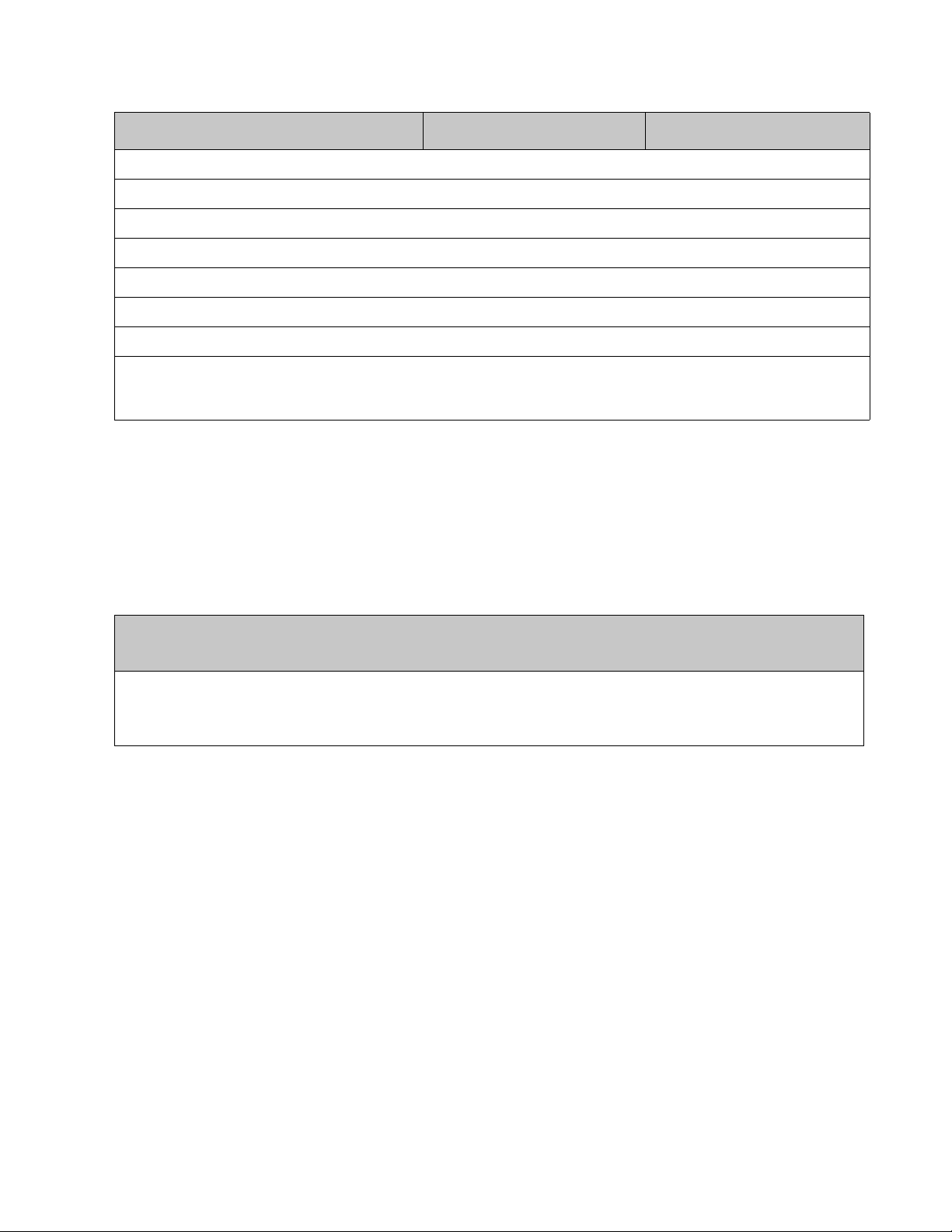
A. Mount length identifier
B. Mount style identifier
3-9000-744 Rev F September 2013
11
12
13
14
15
16
Section 1: Introduction
1.1 Overview
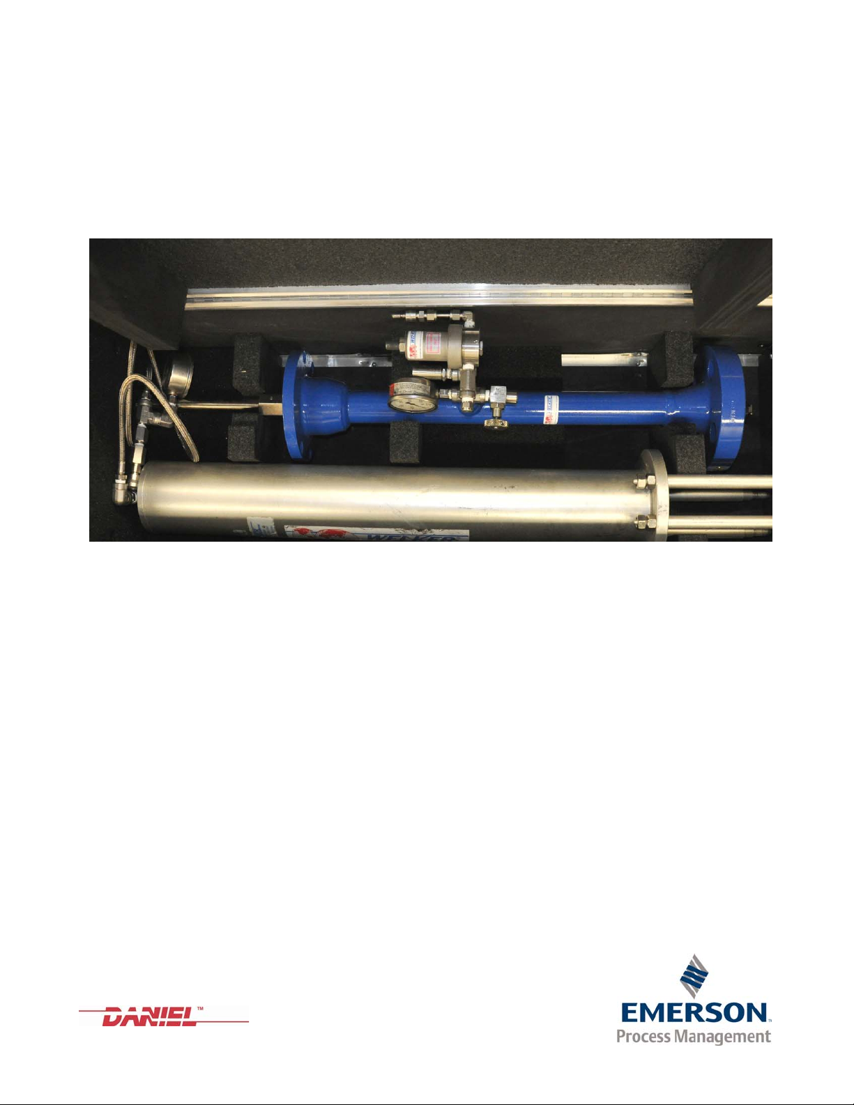
The Daniel Ultrasonic Split Clamp Extractor Tool is designed for use on Daniel SeniorSonicTM
4 Path Gas Ultrasonic Meters only. The Daniel Ultrasonic Split Clamp Extractor Tool Operation
Manual (P/N 3-9000-744) provides operating instructions for 4 Path meters fitted with T- Slot
design transducer mounts (see Figure 1-2). The following mounts are included:
• 150 ANSI to 600 ANSI Ultrasonic meters with style J mounts (example J00, J25, J50 and
J75)
• 900 ANSI and 1500 ANSI Ultrasonic meters with style K mounts (example K00, K25,
K50, and K75)
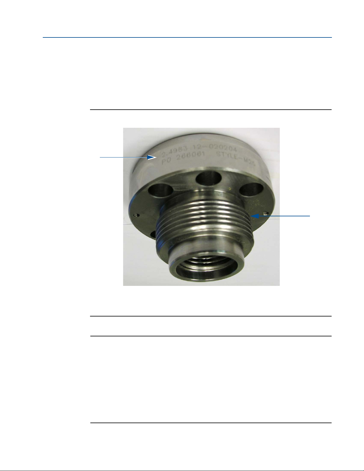
All transducer mounts and holders are stamped, identifying the mount length, mount style,
serial number, and purchase order information (see Figure 1-1 and) Figure 1-2).
Figure 1-1 J-mount transducer identification
Overview 1
Page 16
Section 1: Introduction Operation Manual
A.
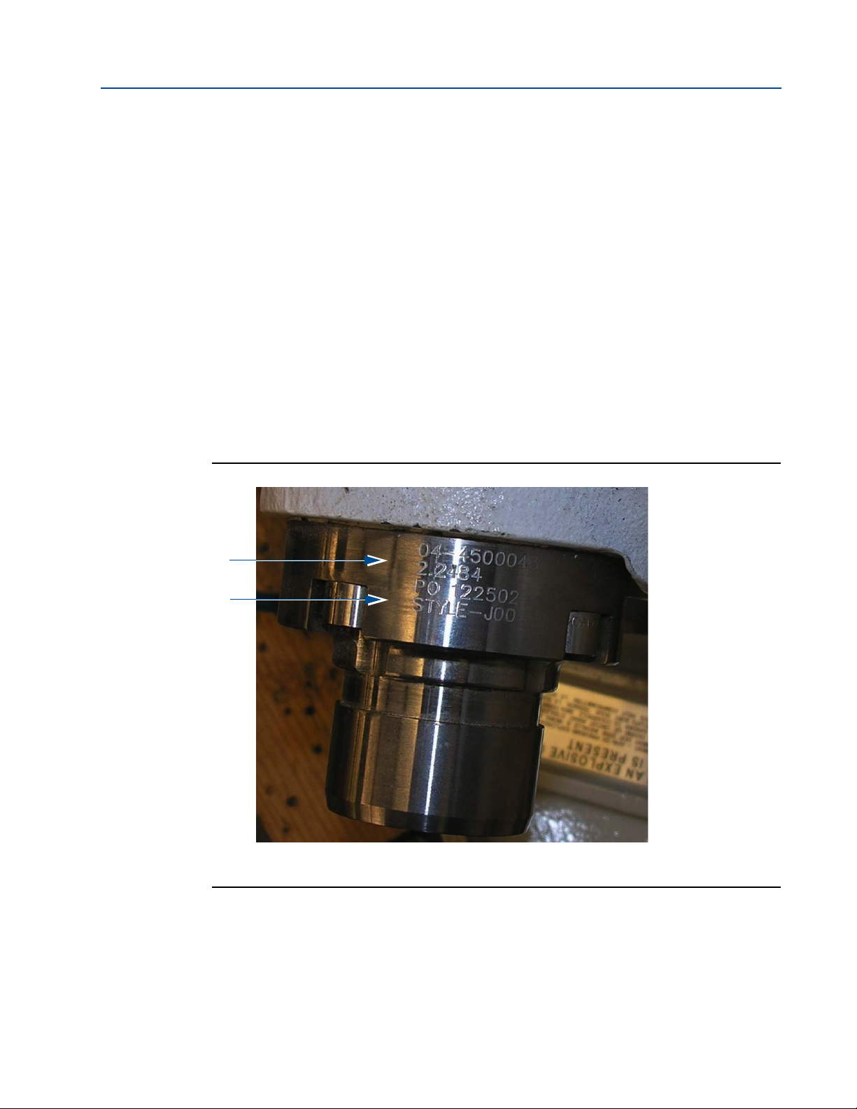
A. Mount identification (serial number, length, purchase order number and style)
B. T-slot transducer holder
B.
September 2013 3-9000-744 Rev F
Figure 1-2 J-mount transducer identification
2 Overview
Page 17
Operation Manual Section 1: Introduction
A.
A. Mount identification (serial number, length, purchase order number and style)
B. Threaded mount
B.
38⁄
38⁄
3-9000-744 Rev F September 2013
Daniel Ultrasonic meters with M-mount (150 ANSI to 600 ANSI) or P-mount
(900 ANSI to 1500 ANSI) T- slot transducer holders are not designed for the Split Clamp
Extractor Tool and this manual does not apply to these mount styles. M-mount and P-mount
bodies are threaded to accept extractor tool coupling and will not accept split clamp extractor
tool (see Figure 1-3). Refer to the Daniel Ultrasonic Extractor Tool Operation Manual,
Daniel P/N 3-9000-729 for threaded body types.
Figure 1-3 M-mount transducer identification
Important:
The ultrasonic extractor tool requires a valve with an NPT female threaded port as a pressure
point for the line pressure. This valve must be installed within six inches of the ultrasonic meter
pressure tap hole provided on the ultrasonic meter housing.
For ANSI #300 and #600 meters, use a valve with a ¼”or ½” NPT female threaded port.
The ¼” reducer provided in the tool kit must be used with the ½” NPT female threaded port.
For ANSI #900 and #1500 meters, use a valve with a “or ½” NPT female threaded port. The
“reducer provided in the tool kit must be used with the ½”NPT female threaded port.
Overview 3
Page 18
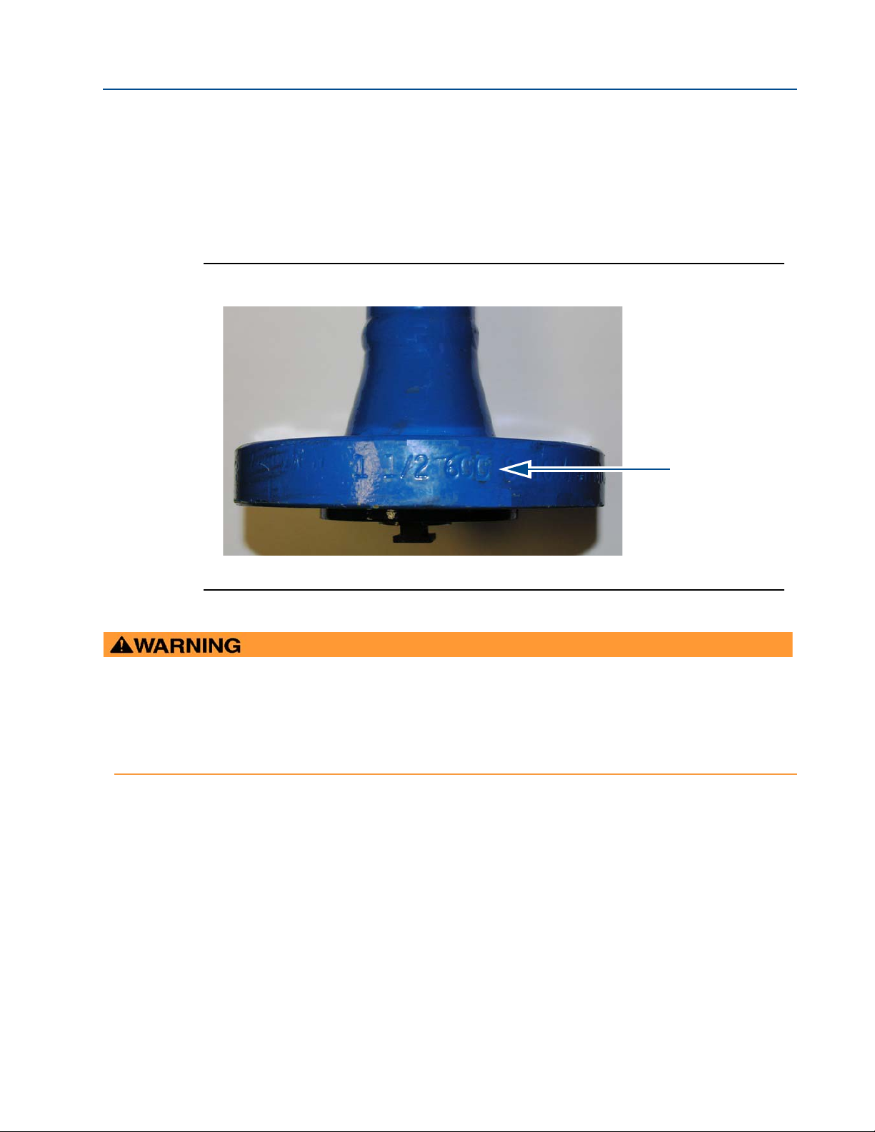
Section 1: Introduction Operation Manual
A.
A. ANSI Class pressure rating identification location
EXTRACTOR TOOL HANDLING HAZARD
The extractor tool, when it is fully assembled is heavy (144-160 lbs), long (6 ft) and may be difficult to operate in
tight quarters. Take care not to lean on, sit on, or step on the unit.
Failure to follow the handling instructions may cause the tool to fall and cause serious personal injury.
September 2013 3-9000-744 Rev F
1.2 Extractor tool specifications
The Daniel Extractor Tool is available in two ANSI pressure ratings, 600 and 1500. The pressure
rating is stamped on the Lubricator chamber assembly flange (item M, drawing D-08248). See
Appendix C and Figure 1-4.
Figure 1-4 ANSI Class pressure rating stamp on lubricator chamber assembly flange
4 Extractor tool specifications
Page 19
Operation Manual Section 1: Introduction
HAZARDOUS MATERIALS
Do not use the Daniel Extractor Tool in environments with hydrogen sulfide present. The tool is
not designed for use in these environments.
Failure to follow these instructions will cause death from asphyxiation, fire, or explosion.
3-9000-744 Rev F September 2013
Table 1-1 Daniel extractor tool specifications
Extractor tool weight by disassembled component Weight (lbs),
ANSI 600 ANSI 1500
Suitcase 52 52
Extractor tool valve assembly (Split clamp) 24 30
Lubricator chamber assembly 32 42
Extractor tool piston assembly 15 15
2 hoses (one black and one stainless steel) 4 4
Tool kit 17 17
Extractor tool total weight 144 160
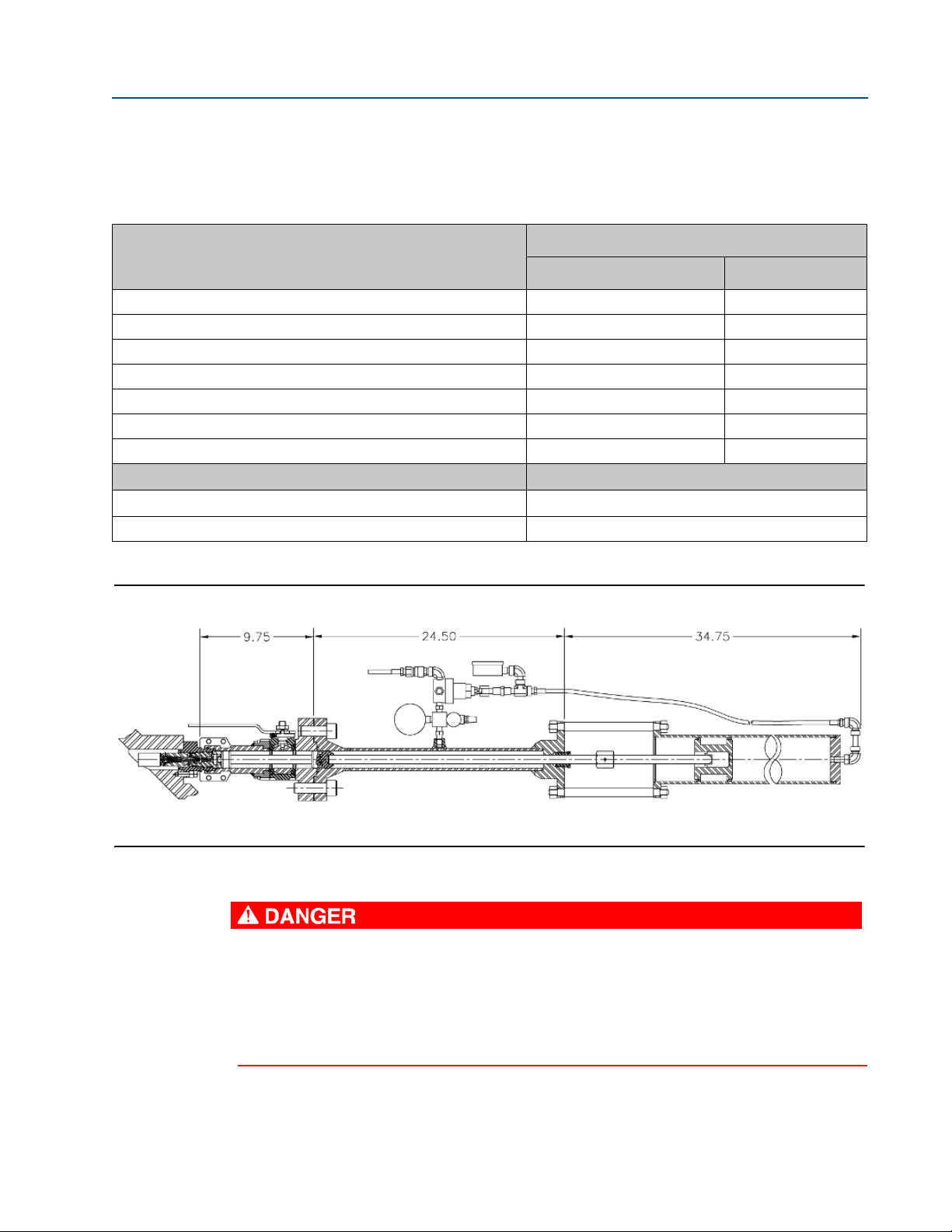
Extractor tool length and operating temperature Length and operating temperature range
Tool length
Operating temperature - 4 °F to 212 °F (-20 °C to 100 °C)
(see Figure 1-5)
Figure 1-5 Split clamp extractor tool assembly dimensions (inches)
Extractor tool specifications 5
Page 20

Section 1: Introduction Operation Manual
September 2013 3-9000-744 Rev F
1.3 Extractor tool pre-use and post-use inspection
Prior to and after using the extractor tool, the following inspection procedure must be followed:
Refer to drawing D-08248 Detail D (see Appendix C).
1. Prior to connecting the Lubricator Chamber Assembly to the Piston Assembly verify
the extractor rod (N) on the Lubricator Chamber Assembly is correctly indicating by
performing the following steps.
a. Make sure the extractor rod is clean and free of dirt and it smoothly pulls in and
out of the Lubricator Chamber Assembly.
b. Grasp the extractor rod (N) and gently pull it out until it stops.
c. The scribe mark at the end of extractor rod (N) is clearly visible.
2. Visually verify that all hoses are intact with no kinks or tears.
3. Visually inspect the four bolts that hold the Piston Assembly onto the Lubricator
Chamber Assembly. Make sure they are clean and that the threads are not galled,
stripped or damaged.
4. Make sure that there are at least eight (8) backup O-Rings
replace all transducer holders extracted. If not enough, order enough for current and
uture use. See Daniel Service Group for O-Ring part numbers.
f
5. Perform a bench test to verify the pressure gauge and regulator on the Lubricator
Chamber Assembly are working properly. Follow Section 4.1, Step 1C to Step 6A in this
manual to prepare the Extractor tool for the bench test.
a. Close the Extractor Tool Valve (H) and use 300 psi nitrogen pressure to pressurize
the extractor tool.
b. Visually verify that there are no leaks at the NPT thread connections. Use Snoop
or soapy water solution for this visual leak check.
c. Confirm that the Lubricator Chamber Assembly line pressure gauge (T) is
indicating the correct line pressure. Adjust the regulator (V) to the required
piston pressure (
Piston Assembly gauge (U) indicates according to Tab le A -1 .
d. Check all Joints including ball seal for leaks using Snoop or a soapy water solution.
Turn the line pressure valve off. Use the Lubricator Chamber vent valve (R), and
bleed the line pressure from the tool. Confirm that both gauges show a slow
decrease in pressure until zero pressure is reached.
e. Close the vent valve (R).
see pressure references Table A-1 Appendix A). Verify that the
and enough lubricant to
®
6 Extractor tool pre-use and post-use inspection
Page 21

Operation Manual Section 1: Introduction
3-9000-744 Rev F September 2013
6. Use USM Extractor Tool pre-use and post-use Inspection checklist (see Appendix B) to
log the inspection and to report any issues found.
7. All technicians who use the extractor tool must take and successfully pass the Daniel
Extractor Tool course prior to using this tool. Technicians who do not pass the Daniel
Extractor course must not use the extractor tool until they repeat and pass the course.
The service manager must verify that the technicians are trained and have successfully
passed the Daniel Extractor Tool course before operating the extractor tool.
8. The Daniel Extractor Tool course must be retaken every two years to ensure safe use of
the tool
. The service manager must verify that all technicians operating the extractor
tool retake the Daniel Extractor Tool course once every two years.
Extractor tool pre-use and post-use inspection 7
Page 22

Section 1: Introduction Operation Manual
September 2013 3-9000-744 Rev F
8 Extractor tool pre-use and post-use inspection
Page 23

Operation Manual Section 2: Operation preparation and part replacement notes
3-9000-744 Rev F September 2013
21
Section 2: Operation preparation and part
replacement notes
2.1 Operation preparation
1. These instructions refer to details and symbols identified on Daniel Measurement and
Control drawing D-08248 (see Appendix C). This operation instruction procedure
applies to T-slot design transducer mount assemblies on Daniel SeniorSonic™
ultrasonic meters only using an extractor tool. The extractor tool uses line pressure to
extract the transducer assembly (J).
2. If line pressure is vented from the meter, the transducer can be removed without using
the extractor tool. See the Daniel Ultrasonic Gas Flow Meter Reference, Installation and
Operation Manual 3-9000-743, for T-slot transducer assembly (J) replacement with line
pressure vented.
3. Always use protective equipment. Proper protective equipment in accordance with the
customer’s regulations and site standard operating procedures is required prior to
operation of the extractor tool. A thorough job safety analysis should be done for all
procedures. Protective equipment may include the following:
• eyewear
• footwear
• hearing protection
• gloves
• hard hat
Operation preparation 9
Page 24

Section 2: Operation preparation and part replacement notes Operation Manual
SURFACE TEMPERATURE HAZARD
Meter body and piping may be extremely hot or cold. Wear personal protective
equipment when coming in contact with the meter.
Failure to do so may result in injury.
EQUIPMENT HANDLING AND LIFTING HAZARD
Extractor tool weight and length and the varying pipeline height requires two service
technicians to safely handle and install the equipment.
Pipeline installations may be higher or lower than waist level or in confined spaces. Proper
scaffolding, provided by the customer, is required to position the technicians at waist level
with extractor tool.
Failure to use recommended number of personnel when installing, handling, lifting, bending
and twisting could cause the tool to become unstable or dropped and result in injury to
personnel or cause damage to the equipment.
NOISE HAZARD - HEARING LOSS
Uncontrolled release of pressurized product may cause hearing discomfort. Wear proper
ear protection when operating the extractor tool.
Failure to do so can result in injury.
September 2013 3-9000-744 Rev F
Important safety information
10 Operation preparation
Page 25

Operation Manual Section 2: Operation preparation and part replacement notes
CUTTING OR CRUSHING HAZARD
Do not permanently attach any tool (e.g., a ratchet) to the extractor tool. High line
pressure increases the velocity of moving parts which may cut or crush extremities.
Failure to keep extremities clear of the moving parts (e.g., pistons or piston rod) may cause
injury to personnel.
NOISE HAZARD - ORAL COMMUNICATION
Release of pressurized product makes communication with operators and service
technicians difficult.
Operators must develop a method of communication prior to using the extractor tool. Failure to
do so can result in injury.
TRIPPING HAZARD
Clear all obstacles or obstructions from the work area when transporting, handling,
installing or removing the extractor tool.
Failure to keep work areas clear of obstacles and obstructions could result in injury or equipment
damage.
3-9000-744 Rev F September 2013
4. Oral communication must be established prior to depressurizing the line, if required.
5. Enough lighting to see the gauge is required prior to extractor tool usage.
6. Allow at least eight (8) feet of clearance to assemble and install the extractor tool.
Operation preparation 11
Page 26

Section 2: Operation preparation and part replacement notes Operation Manual
September 2013 3-9000-744 Rev F
2.2 Part replacement notes
1. The following instructions are for removal and installation of one transducer assembly
(J). Repeat the following steps for each transducer assembly removal or installation
2. For accurate operation, do not exchange any transducer assembly part or parts from
the meter chord path designated by the Daniel manufacturing facility. See notes 4, 5
and 6 below for further instruction.
3. Transducer assemblies (J) in good working condition can be removed, cleaned and
reinstalled.
4. When a transducer assembly (J) is replaced, it is necessary for accurate operation to
modify the calibration parameters for the chord in which the transducer assembly
exchange occurred. This means modifying the ultrasonic meter electronics Modbus
registers for "L", Average Delay Time and Delta Delay Time for the affected chord.
5. Transducer assemblies (J) are always replaced in pairs on any given chord path. The
Average Delay Time and Delta Delay Time are included on a Calibration Sheet provided
with each transducer assembly (J) pair. The length of each transducer assembly (J) is also
provided on the Calibration Sheet, as well as, etched on the transducer assembly
external surface. See Note 7and Note 8 below for further instructions.
6. When a transducer stalk assembly (D) and/or transducer holder (K) is replaced, it is
necessary for accurate operation to modify the calibration parameters for the chord in
which the transducer parts exchange occurred. This means modifying the ultrasonic
1
meter electronics Modbus
transducer stalk assembly (D) and transducer holder (K) is etched on the part’s exterior
surface. See Note 7 and Note 8 below for further instructions.
7. The value "L" is determined by adding the length of the meter housing chord to the
lengths of the transducer mounts (E) and subtracting the lengths of the transducer
assemblies (J), transducer stalk assemblies (D) [if fitted] and transducer holders (K). The
length of the meter housing chord paths and transducer mounts (E) are given on the
original calibration sheet provided with the ultrasonic meter. The length of each
transducer mount (E) is marked on the rim of the part.
registers for "L" for the affected chord. The length of each
8. Transducer stalk assemblies (D) are available in two inch increments of length. The style
of each part is identified by the markings on the exterior surface. Example: STYLE - S2,
STYLE - S4, STYLE - S6...etc. Transducer holders (K) are available in two lengths H1 and
H2. The H2 stalk is one inch longer than the H1 stalk. By design each ultrasonic meter
chord path has been fitted with the appropriate style of transducer stalk assembly (D)
and transducer holder (K) best suited for that transducer location. Some transducer
locations do not require a transducer stalk assembly (D). In these cases the transducer
assembly (J) is connected directly to the transducer holder (K). When replacing a
transducer stalk assembly (D) and/or transducer holder (K) it is important for accurate
operation that the exact replacement style be used.
9. The electrical circuits connecting the ultrasonic meter transducers (J) to the ultrasonic
meter electronics are intrinsically safe circuits. This feature allows these circuits to be
safely disconnected and connected in a hazardous atmosphere without the need to
disconnect power to the ultrasonic meter electronics. If the meter has more than one
pair of transducers, meter operation will only be slightly impaired by the disruption of
one pair of transducers at a time. Flow and flow measurement can continue during
extractor tool operation.
12 Part replacement notes
Page 27

Operation Manual Section 3: Tool requirements
3-9000-744 Rev F September 2013
Section 3: Tool requirements
3.1 Tool list for the extractor tool with T-slot extractable transducers
Table 3-1 Extractor tool list for T-slot extractable transducers
Too l Tool requirement
3/4” Allen wrench Fits cap screws (Z).
5/16” Allen wrench Fits cap screws that attach the transducer mount (E) to the meter housing.
3/32” Allen wrench Fits the extractor tool valve assembly (H) handle stop peg set screw (HH)
1/16” Allen wrench Fits the transducer holder (K) and transducer stalk assembly (D) set screws (W).
¾” x ¾” open/box wrench
¼” open end wrench
1-
Molykote 111
Nickel Anti-Seize
(P/N 9-9960-134)
Screw driver - flat blade To adjust the pressure regulator (V) adjustment screw.
Liquid leak detection fluid Check all joints for sealing integrity. (Not provided by Daniel Measurement and Control.)
1
Fits nuts (X) which attach the piston assembly (P) to the lubricator chamber assembly (M).
Fits lubricator chamber extractor rod (N) hexagon nut and transducer holder (K) hexagon
end.
Valve lubricant and sealant to lubricate O-rings before installation.
Anti-seize thread compound for transducer holder (K).
1
Molykote III is a trademark of Dow Corning Corporation, U.S.A.
Tool list for the extractor tool with T-slot extractable transducers 13
Page 28

Section 3: Tool requirements Operation Manual
September 2013 3-9000-744 Rev F
14 Tool list for the extractor tool with T-slot extractable transducers
Page 29

Operation Manual Section 4: Removing a transducer assembly
HIGH PRESSURE HAZARD
The ANSI pressure rating is stamped on the extractor tool flange. The customer is required
to provide site line pressure. Do not exceed the maximum pressure rating of the extractor
tool.
Exceeding the extractor tool pressure rating may cause personal injury from explosion.
FAULTY EXTRACTOR TOOL INSTALLATION
Do not loosen transducer holders under line pressure without the extractor tool fully
installed.
Loosening the transducer holders at full pressure may cause thread damage and leaks.
3-9000-744 Rev F September 2013
41
Section 4: Removing a transducer assembly
4.1 Steps to remove a transducer assembly from a meter while the meter is under line pressure
1. Refer to Drawing CE-21060 DETAIL “A” (Appendix C).
a. Fully unscrew the chordset coupling nut (C).
b. Grasp the chordset assembly (A) and pull the chordset assembly away from the
transducer mount (E). This unplugs the chordset socket (B) from the transducer
holder (K). Position the chordset assembly (A) out of the way of the transducer
mount (E) for the duration of the transducer assembly (J) removal and
installation.
2. Refer to Drawing CE-21061 DETAIL “B” (Appendix C).
a. Check to make sure the extension (L) fits into the extractor tool valve assembly
(H) without catching.
b. Slide the male T end of the extension (L) into the T-slot in the hexagon end of the
transducer holder (K). Align the extension (L) with the transducer holder (K).
Steps to remove a transducer assembly from a meter while the meter is under line pressure 15
Page 30

Section 4: Removing a transducer assembly Operation Manual
FAULTY EXTRACTOR TOOL INSTALLATION
Install the extractor tool split clamp securely to the transducer mount and make sure it is
properly seated and not loose.
Improperly seated or loose split clamp may cause the unit to fall and result in injury to personnel
or cause damage to the equipment.
September 2013 3-9000-744 Rev F
3. Refer to Drawing CE-21062 DETAIL “C” (Appendix C).
a. Verify that the seal and backup seal are present on the split clamp end of the
extractor tool valve assembly (H). Apply a small amount of valve lubricant
Molykote 111 or equivalent lubricant to the O-ring seal.
b. Using the valve handle, fully open the extractor tool valve assembly (H). The valve
is in the full open position when the valve handle contacts the valve handle stop
peg set screw (HH).
Important:
If the extractor tool valve assembly (H) is in the closed position, the valve close stop button (S)
must be depressed while the valve handle is moved to the open position.
c. Slide the extractor tool valve assembly (H) over the extension (L) which has been
positioned as described in Step 2 above.
d. Position the split clamp end of the extractor tool valve assembly (H) over the
transducer holder (K) and push the split clamp end of the extractor tool valve
assembly (H) over the end of the transducer mount (E) securing the O-ring seal of
the extractor tool valve assembly (H).
Important:
If the extractor tool valve assembly (H) does not easily pass over the extension (L) the valve may
not be in the full open position. Use the valve handle stop peg set screw (HH) to adjust the valve
to the full open position. It is important that the extension (L) freely passes through the
extractor tool valve assembly (H) when the valve handle is in contact with the valve handle stop
peg set screw (HH).
e. Install each half of the split clamp (F) over the split clamp end of the extractor tool
valve assembly (H). The flanged end of the split clamp (F) is to be closest to the
mount (E). Engage the ridges in the I.D. of the split clamp (F) into the slots in the
mount (E) and extractor tool valve assembly (H).
f. Rotate the extractor tool valve assembly (H) to position the valve stem in a
horizontal plane.
g. Secure the halves of the split clamp (F) with four screws (G). Tighten to 20
foot-pounds of torque in a star pattern between the two halves of the split clamp.
16 Steps to remove a transducer assembly from a meter while the meter is under line pressure
Page 31

Operation Manual Section 4: Removing a transducer assembly
VIBRATION HAZARD
Excessive vibration on the pipeline may cause the extractor tool to vibrate. Such vibration
could cause a gas leak or other hazard. If the installed unit experiences excessive vibration,
discontinue use of the extractor tool.
If this occurs, depressurize the meter and then remove the transducers.
3-9000-744 Rev F September 2013
4. Refer to Drawing CE-21063 DETAIL “D” (Appendix C).
a. Clean the lubricator chamber assembly (M) end flange sealing face. Clean the
extractor tool valve assembly (H) flange sealing face. Verify that the O-ring (JJ)
located at the flange end between the lubricator chamber assembly (M) and
valve assembly (H) (see Figure 4-2) is not damaged. Contact Daniel Customer
Service if replacement is necessary. Apply a small amount of Molykote 111 valve
lubricant or equivalent lubricant to the O-ring seal.
Figure 4-2 Extractor tool with O-ring on flange
b. Extend the lubricator chamber extractor rod (N) from the end of the lubricator
chamber assembly (M) exposing the male T on the end of the rod. Connect the
extractor rod (N) male T to the end T-slot of the extension (L).
c. Attach the lubricator chamber assembly (M) flange to the extractor tool valve
assembly (H) flange with four cap screws (Z). Use the longer cap screw (Z) in the
top bolt hole location which is not in line with the extractor tool valve assembly
(H) valve stem. Rotate the lubricator chamber assembly (M) in such a way that
convenient access to the valves and gauges of the lubricator chamber assembly
(M) is obtained. Securely tighten all cap screws (Z). Minimize the rotation of the
extractor tool assembly while tightening the screws.
Steps to remove a transducer assembly from a meter while the meter is under line pressure 17
Page 32

Section 4: Removing a transducer assembly Operation Manual
HIGH PRESSURE HAZARD
The ultrasonic meter housing line pressure valve (Q) is to remain closed until both ends of
the high pressure hose are securely connected.
Failure to keep the valve closed until the ends of the hose are securely connected may result in
personal injury from explosive forces.
September 2013 3-9000-744 Rev F
d. Attach extractor tool piston assembly (P) to lubricator chamber assembly (M) by
aligning the extractor tool piston assembly (P) end bolts with the lubricator
chamber assembly (M) flange bolt holes. During this assembly insert the
extractor rod (N) into the center hole of the piston of the extractor tool piston
assembly (P). If it is necessary to move the piston to allow assembly, push the
piston against the extractor rod (N). During this process the air within the piston
cylinder must be vented through the piston orifice fitting (Y) so movement will
be slow. Install and tighten the four nuts (X). Minimize the rotation of the
extractor tool assembly during nut tightening.
e. Connect the quick connect body (BB) on the end of the low pressure hose
attached to the extractor tool piston assembly (P) to the quick connect stem
(DD) on the low pressure (secondary) port of the pressure regulator (V).
f. Fully loosen the pressure regulator (V) adjustment screw.
g. Close the lubricator chamber vent valve (R). The extractor tool valve assembly (H)
must remain in the full open position.
5. Refer to Drawing D-08248 (Appendix C).
a. Install the meter housing quick connect stem (FF) to the ultrasonic meter
housing line pressure valve (Q). If required, use the reducer provided with the
tool kit.
b. Connect the quick connect body (AA) on one end of the high pressure hose to
the quick connect stem (FF) on the ultrasonic meter housing line pressure valve
(Q) - Customer Supplied - (Refer to Appendix C - Drawings, note Q typical).
18 Steps to remove a transducer assembly from a meter while the meter is under line pressure
Page 33

Operation Manual Section 4: Removing a transducer assembly
LINE PRESSURE HAZARD
The meter line pressure controls the motion of the exposed lubricator extractor rod.
Moving parts may cause cutting or crushing to extremities during operation.
Failure to keep extremities clear of the extractor rod may cause injury to personnel.
LEAKAGE HAZARD
If a leak is detected, immediately stop and depressurize the extractor tool as described
above.
Failure to repair all leaks could result in personal injury from explosive forces or asphyxiation.
3-9000-744 Rev F September 2013
6. Refer to Drawing CE-21064 DETAIL “E” (Appendix C).
a. Connect the quick connect body (AA) on the remaining end of the high pressure
hose to the quick connect stem (CC) on the high pressure (primary) port of the
pressure regulator (V).
b. Open the ultrasonic meter housing line pressure valve (Q) to pressurize the
lubricator chamber. Continue to pressurize the lubricator chamber until
lubricator pressure gauge (T) indicates the chamber reaches line pressure.
c. Check all joints of the ultrasonic meter housing line pressure valve (Q), high
pressure hose fittings, lubricator chamber assembly (M) and extractor tool valve
assembly (H) for leaks with a leak detection solution.
d. If a leak is detected, immediately stop. Depressurize the extractor tool by closing
the ultrasonic meter housing line pressure valve (Q) and opening the lubricator
chamber vent valve (R).
e. Repair the leaking joint, close the lubricator chamber vent valve (R) and
repressurize the lubricator chamber as described above.
Steps to remove a transducer assembly from a meter while the meter is under line pressure 19
Page 34

Section 4: Removing a transducer assembly Operation Manual
September 2013 3-9000-744 Rev F
f. Adjust the pressure on the extractor tool piston assembly (P) to exceed the force
of line pressure exerted on the extractor rod (N). Refer to Tab le A- 1 piston and line
pressure chart. To do this,
– Slowly rotate the pressure regulator (V) adjustment screw in a clockwise
direction.
– Monitor the line pressure indicated on the lubricator chamber pressure
gauge (T).
– Continue turning the adjustment screw until the extractor tool piston
assembly (P) pressure indicates the line pressure shown in Table A-1.
– The outside surface of the piston assembly (P) cylinder lists a
corresponding piston pressure chart for the line pressure measured on
the lubricator chamber pressure gauge (T).
g. Using an open end 1-¼” wrench on the hex of the lubricator chamber extractor
rod (N), fully unscrew the transducer holder (K) from transducer mount (E). As
the extractor rod (N) is rotated in the counter-clockwise direction watch for
lateral movement of the extractor rod (N). When the lateral movement no longer
occurs the transducer holder (K) is completely free of the transducer mount (E).
h. Reduce the pressure of the extractor tool piston assembly (P) by fully unscrewing
(counter-clockwise) the adjustment screw of the pressure regulator (V) until
loose. The piston orifice fitting (Y) will slowly allow pressure to vent from the
extractor tool piston assembly (P) causing the extractor rod (N) to slowly retract
to a fully retracted position which is indicated by the visibility of a mark on the
extractor rod (N) at the end of the lubricator chamber assembly (M). If the
extractor rod (N) becomes jammed, which may be indicated by the stopping of
the movement of the extractor rod (N) before the piston is fully retracted, verify
that the extractor tool valve assembly is in the full open position.
Important
The extractor tool is designed with a shear pin safety device intended to shear off
if the transducer holder is frozen or galled in place. If the shear pin is sheared off,
stop the extraction procedure and blow the line down.
20 Steps to remove a transducer assembly from a meter while the meter is under line pressure
Page 35

Operation Manual Section 4: Removing a transducer assembly
INHALATION HAZARD
Escaping gases released when line is vented may be toxic. Do not inhale the gases vented
to the atmosphere from the pipeline. Do not position yourself directly in front of vented
gases.
Failure to avoid inhaling vented gases may result in injury.
3-9000-744 Rev F September 2013
i. Verify all pressure has been vented from the extractor tool piston assembly (P) by
reading the piston pressure gauge (U). Do not proceed until piston pressure
gauge (U) indicates zero pressure, and the extractor rod has stopped moving.
j. Verify that the mark on the extractor rod (N) is visible at the packing gland end of
the lubricator chamber assembly (M). Do not proceed until the extractor rod (N)
is fully retracted to avoid possible transducer assembly (J) damage by closing the
extractor tool valve assembly (H) with the transducer assembly (J) within the ball
of the valve.
k. Close the extractor tool valve assembly (H). The valve handle will automatically
lock the valve in the closed position. If the valve will not close, the transducer
assembly (J) may not be fully retracted. See Step f above.
l. Fully close the ultrasonic meter housing line pressure valve (Q) and vent all
pressure from the lubricator chamber assembly (M) by opening the lubricator
chamber vent valve (R). The lubricator chamber pressure gauge (T) should
indicate zero pressure.
Steps to remove a transducer assembly from a meter while the meter is under line pressure 21
Page 36

Section 4: Removing a transducer assembly Operation Manual
SEALING HAZARD
If the lubricator chamber pressure gauge (T) indicates pressure in the lubricator chamber
assembly (M) after a period of time, the extractor tool valve assembly (H) seals may be
leaking. If this is observed proceed to Section 4.1, Step 1A) of the instructions “Steps to
install a transducer assembly while the meter is under line pressure” and re-install the
transducer holder (K).
Failure to repair all leaks could result in personal injury from explosive forces or asphyxiation.
September 2013 3-9000-744 Rev F
m. To check the sealing integrity of the extractor tool valve assembly (H), close the
lubricator chamber vent valve (R). Wait several minutes and observe lubricator
chamber pressure gauge (T). If zero pressure is indicated by the gauge, this
confirms that sealing is successful. Open the lubricator chamber vent valve (R).
7. Refer to Drawing D-08248 DETAIL “G” (Appendix C).
a. Remove the meter housing quick connect stem and reducer if it was required.
Return the parts to the tool kit.
b. Disconnect the high pressure hose quick connect body (AA) from quick connect
stem (FF) on the ultrasonic meter housing line pressure valve (Q). Disconnect the
high pressure hose quick connect body (AA) from quick connect stem (CC) on
the pressure regulator (V) high pressure (primary) port.
c. Disconnect the low pressure hose quick connect body (BB) from the quick
connect stem (DD) on the pressure regulator (V) low (secondary) pressure port.
Wrap the low pressure hose around the extractor tool piston assembly (P) and
connect the low pressure hose quick connect body (BB) to the quick connect
stem (EE) located on the extractor tool piston assembly (P) flange for storage.
8. Refer to Drawing CE-21065 DETAIL “F” (Appendix C).
a. Loosen and remove the four extractor tool piston assembly (P) nuts (X) from the
flange on the lubricator chamber assembly (M). Minimize the rotation of the
extractor tool assembly during nut removal. Remove the extractor tool piston
assembly (P) from the lubricator chamber assembly (M). For safe keeping
reinstall the nuts (X) after removal.
22 Steps to remove a transducer assembly from a meter while the meter is under line pressure
Page 37

Operation Manual Section 4: Removing a transducer assembly
90o position
270o position
Valve assembly flange
0
o
position180o position
3-9000-744 Rev F September 2013
b. Loosen all four of the lubricator chamber cap screws (Z) on the lubricator
chamber assembly (M) flange from the extractor tool valve assembly (H) flange.
Minimize the rotation of the extractor tool assembly during screw removal.
Remove the three short lubricator chamber cap screws (Z), but do not remove
o
the one long lubricator chamber cap screw located at the 90
position. Loosen
this screw so the end of the screw is flush with the back side of the extractor tool
valve assembly (H) flange.
Figure 4-3 Lubricator chamber assembly flange screws
c. Pull on the lubricator chamber assembly (M) to disconnect the lubricator
chamber assembly (M) flange from the extractor tool valve assembly (H) flange.
Pivot the lubricator chamber on the remaining long cap screw.
o
d. Reinstall a short cap screw at either the 0
or the 180o position
(see Figure 4-3) and rest the lubricator chamber flange on the reinstalled short
cap screw. This is to leave the lubricator chamber assembly (M) bore exposed.
e. Push on the lubricator chamber extractor rod (N) exposing the transducer
assembly (J), transducer stalk assembly (D) [if fitted], transducer holder (K), and
the end of the extension (L) from the end of the lubricator chamber
assembly (M).
f. Grasp the transducer holder (K) and disconnect the T-slot in the end of the
transducer holder (K) from the extension (L) T end.
Steps to remove a transducer assembly from a meter while the meter is under line pressure 23
Page 38

Section 4: Removing a transducer assembly Operation Manual
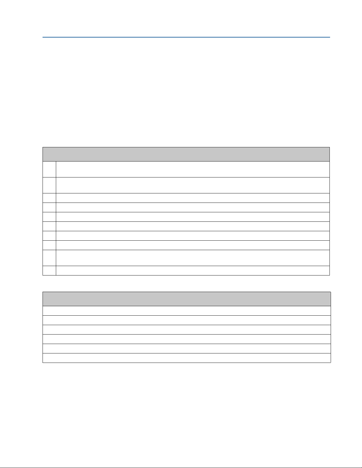
A.
B.
E.
A. Transducer holder
B. Transducer holder set screws
C. Transducer stalk assembly
C.
D. Transducer stalk assembly set screws
D.
E. Transducer assembly
September 2013 3-9000-744 Rev F
g. Remove the transducer assembly (J) (Figure 4-4, E) from the transducer stalk
assembly (D) (Figure 4-4, C) or, on some meters, the transducer holder (K)
(Figure 4-4, A) by unscrewing the three set screws (W) (Figure 4-4, D) on the
transducer stalk assembly (D) or, transducer holder (K) (Figure 4-4, B). Clean or
replace the transducer assembly (J) as needed.
Figure 4-4 Transducer holder, stalk and transducer assembly
h. Review the Part Replacement notes in Section 2.2 for instructions on
replacement of transducer assemblies (J) and other mounting parts.
24 Steps to remove a transducer assembly from a meter while the meter is under line pressure
Page 39

Operation Manual Section 5: Installing a transducer assembly
3-9000-744 Rev F September 2013
51
Section 5: Installing a transducer assembly
5.1 Installing a transducer assembly while the meter is under line pressure
1. Refer to Drawing CE-21065 DETAIL “F” (Appendix C).
a. Review the notes in Section 2.2 at the beginning of this procedure for
instructions on replacement of transducer assemblies (J) and other mounting
parts.
b. Clean the transducer assembly (J), transducer stalk assembly (D), if fitted, and the
transducer holder (K). Take particular care to clean the transducer holder (K)
threads. Replace the O-ring seals on the transducer holder (K).
c. Clean, inspect and replace as needed, the O-ring seal on the male connector end
of the transducer assembly (J).
d. Apply a small amount of valve lubricant or other suitable grease to the O-ring seal
on the male connector end of the transducer assembly (J).
e. Align the slot on the male connector end of the transducer assembly (J) with the
pin within the mating connector female end of the transducer stalk assembly (D),
or the transducer holder (K). Press the two parts together. Equally tighten the
three set screws (W) on the transducer stalk assembly (D), or the transducer
holder (K) securing the transducer assembly (J) in place.
f. With the extension (L) protruding from the flange end of the lubricator chamber
assembly (M) install the transducer holder (K) by engaging the T on the extension
(L) with the T-slot on the transducer holder (K). Once the connection has been
made, retract the extractor rod (N) enough so the T-slot joint is inside the bore of
the lubricator chamber assembly (M). This secures the attachment.
g. Apply an ample amount of anti-seize compound to the threads of the transducer
holder (K). Apply a small amount of valve lubricant or other suitable grease to the
O-rings of the transducer holder (K).
2. Refer to Drawing CE-21064 DETAIL “E” (Appendix C).
a. Fully retract the extractor rod (N) within the lubricator chamber assembly (M).
Confirmation of full retraction is indicated by a mark on the extractor rod (N) at
the end of the lubricator chamber assembly (M). When this mark is visible the
extractor rod (N) is fully retracted.
b. Clean the lubricator chamber assembly (M) end flange sealing face. Clean the
extractor tool valve assembly (H) flange sealing face. Apply a small amount of
valve lubricant or other suitable grease to the O-ring seal on the flange end of the
lubricator chamber assembly (M).
c. Rotate and align the lubricator chamber assembly (M) flange to the extractor tool
valve assembly (H) flange and attach with four cap screws (Z). Securely tighten all
cap screws (Z) evenly, keeping the faces of both flanges parallel. Minimize the
rotation of the extractor tool assembly during screw tightening.
Installing a transducer assembly while the meter is under line pressure 25
Page 40

Section 5: Installing a transducer assembly Operation Manual
September 2013 3-9000-744 Rev F
d. Align the extractor rod (N) into the center hole of the piston of the extractor tool
piston assembly (P). The piston should be fully retracted inside the extractor tool
piston assembly (P).
Important:
If the piston is not fully retracted, use a long rod or dowel to force the piston back into the
extractor tool piston assembly (P). During this process the air within the piston cylinder must be
vented through the piston orifice fitting (Y) so movement will be slow.
e. Attach the extractor tool piston assembly (P) to the lubricator chamber assembly
(M) by aligning the extractor tool piston assembly (P) end bolts with the
lubricator chamber assembly (M) flange bolt holes. Install and equally tighten the
four nuts (X). Minimize the rotation of the extractor assembly during nut
tightening.
f. Connect the quick connect body (BB) on the end of the low pressure hose
attached to the extractor tool piston assembly (P) to the quick connect stem
(DD) on the low pressure (secondary) port of the pressure regulator (V).
g. Ensure that the pressure regulator (V) adjustment screw is fully loosened (coun-
terclockwise).
h. Close the lubricator chamber vent valve (R). The ultrasonic meter housing line
pressure valve (Q) and extractor tool valve assembly (H) are to remain closed.
i. Connect the quick connect body (AA) on one end of the high pressure hose to
the quick connect stem (CC) on the high pressure (primary) port of the pressure
regulator (V).
26 Installing a transducer assembly while the meter is under line pressure
Page 41

Operation Manual Section 5: Installing a transducer assembly
HIGH PRESSURE HAZARD
The ultrasonic meter housing line pressure valve (Q) is to remain closed until both ends of
the high pressure hose are securely connected.
Failure to do so could result in personal injury from explosive forces or sudden whipping of the
line.
3-9000-744 Rev F September 2013
3. Refer to Drawing D-08248 (Appendix C).
a. Connect the quick connect body (AA) on the remaining end of the high pressure
hose to the quick connect stem (FF) on the ultrasonic meter housing line
pressure valve (Q). Customer Supplied - (Refer to Appendix C, Drawings, note Q
typical). Refer to Drawing CE-21063 DETAIL “D” (Appendix C)
b. Open the ultrasonic meter housing line pressure valve (Q) to pressurize the
lubricator chamber to line pressure. Observe line pressure on lubricator chamber
pressure gauge (T) to ensure the lubricator chamber reaches line pressure.
c. Check all joints of the ultrasonic meter housing line pressure valve (Q), high
pressure hose fittings, lubricator chamber assembly (M) and extractor tool valve
assembly (H) for leaks with a leak detecting solution. If any leaks occur
depressurize the extractor tool by closing ultrasonic meter housing line pressure
valve (Q) and open the lubricator chamber vent valve (R). Repair the leaking joint,
close the lubricator chamber vent valve (R) and repressurize the lubricator
chamber as described above.
d. Open the extractor tool valve assembly (H) by depressing the valve close stop
button (S) while moving the handle to the full open position. The valve is full
open when the valve handle contacts the valve handle stop peg set screw (HH).
Installing a transducer assembly while the meter is under line pressure 27
Page 42

Section 5: Installing a transducer assembly Operation Manual
September 2013 3-9000-744 Rev F
e. Adjust the pressure on the extractor tool piston assembly (P) to slightly exceed
the force of line pressure acting on the extractor rod (N).
Slowly rotate the pressure regulator (V) adjustment screw in a clockwise
direction until the extractor tool piston assembly (P) pressure, as shown on the
piston pressure gauge (U), indicates line pressure greater than the piston
pressure as shown in Tabl e A- 1.
For the line pressure indicated on the lubricator chamber pressure gauge (T),
refer to the Extractor Tool Piston Pressure chart or Ta b le A -1 . Once the pressure
given in the chart is achieved, slowly turn the adjustment screw in the clockwise
direction a little farther to allow the force of the pressure to overcome the
friction of the extractor rod (N) seals.
When the piston pressure force exceeds all of the forces acting on the extractor
rod (N), the extra ctor rod (N) will begin to slowly move towards the ultrasonic
meter. Continue until the transducer holder (K) contacts the transducer mount
(E) flange.
f. The hex nut on the extractor rod (N) should be accessible in the open space
between the lubricator chamber assembly (M) and the extractor tool piston
assembly (P). If this does not occur, retract the rod by loosening the pressure
regulator (V) adjustment screw to retract the rod (N).
g. Ensure that the valve (H) is fully open, then repeat this step. When the transducer
holder (K) contacts the transducer mount (F) the threads of the two parts should
automatically align with each other and the rod (N) hex will be accessible in the
open space between the lubricator chamber (M) and piston assembly (P). Use a
1-¼” open end wrench on the hex of the extractor rod (N) to screw the
transducer holder (K) into the transducer mount (E).
As the extractor rod (N) is rotated in the clockwise direction watch for lateral
movement of the extractor rod (N). The lateral movement will confirm thread
engagement. When tight, the transducer holder (K) is completely threaded onto
the transducer mount (E).
Important
The threaded joint of the T-slot transducer holder (K) to the transducer mount (E) does not have
a recommended torque requirement. The transducer holder (K) is to be tightened sufficiently so
the shoulder on the transducer holder (K) is fully seated.
28 Installing a transducer assembly while the meter is under line pressure
Page 43

Operation Manual Section 5: Installing a transducer assembly
EXCESSIVE TORQUE HAZARD
Do not exceed 300 foot-pounds of torque on the extractor rod or the rod nut. Excessive
torque will shear the extractor rod hex nut pin.
Excessive torque applied during operation may cause equipment damage.
SEALING HAZARD
If the transducer holder does not seal, repeat Section 4.1, Step 7, to remove the transducer
holder (K) and replace the seals and/or take other actions as needed to correct the
problem.
Failure to seal line pressure could result in possible personal injury.
3-9000-744 Rev F September 2013
h. Vent the pressure of the extractor tool piston assembly (P) by fully unscrewing
(counterclockwise) the adjustment screw of the pressure regulator (V) until
loose. The piston orifice fitting (Y) will slowly allow pressure to vent from the
extractor tool piston assembly (P). The piston pressure gauge (U) should indicate
zero pressure.
i. Fully close the ultrasonic meter housing line pressure valve (Q) and vent all
pressure from the lubricator chamber assembly (M) by opening the lubricator
chamber vent valve (R). The lubricator chamber pressure gauge (T) should
indicate zero pressure.
j. To check the sealing integrity of the transducer holder (K), close the lubricator
chamber vent valve (R). Wait several minutes and observe lubricator chamber
pressure gauge (T). If no pressure is indicated by the gauge, sealing is successful.
Open the lubricator chamber vent valve (R).
k. If the lubricator chamber pressure gauge (T) indicates pressure in the lubricator
chamber assembly (M) some time after the lubricator chamber vent valve (R) has
been opened to vent pressure and again closed, then the transducer holder (K)
seals may not be sealing line pressure.
Installing a transducer assembly while the meter is under line pressure 29
Page 44

Section 5: Installing a transducer assembly Operation Manual
September 2013 3-9000-744 Rev F
4. Refer to Drawing D-08248 (Appendix C).
a. Remove the meter housing quick connect stem and the reducer if it was
required. Return the parts to the tool kit.
b. Disconnect the high pressure hose quick connect body (AA) from the ultrasonic
meter housing line pressure valve (Q) quick connect stem (FF) and the other high
pressure hose quick connect body (AA) from the quick connect stem (CC) on the
pressure regulator (V) high pressure (primary) port. Remove and store the high
pressure hose.
c. Disconnect the low pressure hose quick connect body (BB) from the quick
connect stem (DD) on the pressure regulator (V) low pressure (secondary) port.
Wrap the low pressure hose around the extractor tool piston assembly (P) and
connect the low pressure hose quick connect body (BB) to the quick connect
stem (EE) located on the extractor tool piston assembly (P) flange for storage.
5. Refer to Drawing CE-21065 DETAIL “F” (Appendix C).
a. Loosen and remove the four extractor tool piston assembly (P) nuts (X). Minimize
the rotation of the extractor tool assembly during nut removal. Pull the extractor
tool piston assembly (P) away from the lubricator chamber assembly (M). For safe
keeping reinstall the nuts (X) after removal. Remove and store the extractor tool
piston assembly (P).
b. Loosen and remove all four of the lubricator chamber cap screws (Z) on the
lubricator chamber assembly (M) flange from the extractor tool valve assembly
(H) flange. Minimize the rotation of the extractor tool assembly during screw
removal. Pull on the lubricator chamber assembly (M) to disconnect the
lubricator chamber assembly (M) flange from the extractor tool valve assembly
(H) flange. During disassembly disconnect the extractor rod (N) end T from the
end of the extension (L) T-slot by extending the extractor rod (N) from the end of
the lubricator chamber assembly (M). Remove and store the lubricator chamber
assembly (M).
6. Refer to Drawing CE-21062 DETAIL “C” (Appendix C).
Loosen and remove the four split clamp screws (G). Remove both halves of the split
clamp (F) and store. When the split clamp (F) is fully disconnected from the
transducer mount (E) pull the extractor tool valve assembly (H) away from the
transducer mount (E). When free of the transducer mount (E) continue to pull the
extractor tool valve assembly (H) while guiding the extension (L) through the bore
of the valve. Remove and store the extractor tool valve assembly (H).
7. Refer to Drawing CE-21061 DETAIL “B” (Appendix C).
Slide the extension (L) end T from the T-slot within the transducer holder (K).
Remove and store the extension (L).
30 Installing a transducer assembly while the meter is under line pressure
Page 45

Operation Manual Section 5: Installing a transducer assembly
LEAKAGE HAZARD
If a leak is detected, repeat the steps to remove a transducer assembly while the meter is
under line pressure (see Section 4.1).
Failure to repair the leaking transducer holder (K) seals could cause exposure to escaping gases
or an explosion resulting in possible personal injury.
3-9000-744 Rev F September 2013
8. Refer to Drawing CE-21060 DETAIL “A” (Appendix C).
a. Use a leak detecting fluid around the joint of the transducer holder (K) to
transducer mount (E) joint to check the seals of the transducer holder (K).
b. Clean, inspect and replace as needed the O-ring seal in the chordset coupling nut
(C). Apply a small amount of valve lubricant or other suitable grease to this
O-ring seal.
c. Grasp the chordset assembly (A). Align the slot in the chordset socket (B) with
the key pin within the transducer holder (K). Connect the chordset socket (B) to
the pins within the transducer holder (K) by pressing the chordset assembly (A)
into the transducer holder (K). After the connection has been made, turn the
chordset coupling nut (C) of the chordset assembly (A) to screw the chordset
coupling nut (C) into the transducer holder (K).
d. Verify the electrical connections by connecting to the meter using Daniel
MeterLink and select the Meter|Monitor (Detailed) view. Check the flow profile,
chord performance, gains, and Signal-to-noise ratios to ensure the transducer
signal quality is good. If transducer assembly parts were replaced with new parts,
review the notes at the beginning of this procedure for instructions on
replacement of transducer assembly parts.
e. Additional transducer assembly extractions require the disassembly of the
extractor tool and require following the disassembly procedure in Section 4.1.
Installing a transducer assembly while the meter is under line pressure 31
Page 46

Section 5: Installing a transducer assembly Operation Manual
September 2013 3-9000-744 Rev F
32 Installing a transducer assembly while the meter is under line pressure
Page 47

Operation Manual Section 6: Maintenance
3-9000-744 Rev F September 2013
61
Section 6: Maintenance
6.1 Extractor tool maintenance
The Split Clamp Extractor Tool must be returned to our factory annually or after fifty (50)
transducer extractions, whichever comes first, for maintenance and recertification for field
operations.
However, in the case of severe operation, dirty conditions, or other unique applications that may
subject the equipment to extreme circumstances, Daniel recommends a more frequent
maintenance schedule.
Extractor tool maintenance 33
Page 48

Section 6: Maintenance Operation Manual
September 2013 3-9000-744 Rev F
34 Extractor tool maintenance
Page 49

Operation Manual Section 7: Parts list
3-9000-744 Rev F September 2013
Section 7: Parts list
7.1 Extractor tool parts list
Table 7-1 Extractor tool parts list
Parts list Description
A Chordset assembly
B Chordset socket
C Chordset coupling nut
D Transducer stalk assembly
E Transducer mount
FExtractor tool valve split clamp
GSplit clamp screws
H Extractor tool valve assembly
J Transducer assembly
K Transducer holder
LExtension
M Lubricator chamber assembly
N Lubricator chamber extractor rod
P Extractor tool piston assembly
Q Ultrasonic meter housing line pressure valve (customer supplied)
R Lubricator chamber vent valve
S Valve close stop button
T Lubricator chamber pressure gauge
UPiston pressure gauge
V Pressure regulator
W Transducer stalk set screws
X Extractor tool piston assembly nuts
Y Piston orifice fitting
Z Lubricator chamber cap screws
AA High pressure hose quick connect body
BB Low pressure hose quick connect body
CC High pressure hose quick connect stem
DD Low pressure hose quick connect stem
EE Low pressure hose quick connect stem (for storage)
FF Meter housing quick connect stem (comes with the extractor tool)
HH Valve handle stop peg set screw
JJ Lubricator chamber assembly O-ring seal
Extractor tool parts list 35
Page 50

Section 7: Parts list Operation Manual
September 2013 3-9000-744 Rev F
36 Extractor tool parts list
Page 51

Operation Manual Appendix A: Piston and line pressure
3-9000-744 Rev F September 2013
A
Appendix A: Piston and line pressure
A.1 Extractor tool piston pressure
Use Tab le A -1 to determine the extractor tool piston pressure needed to stabilize the extractor
tool lubricator chamber extractor rod (N) against line pressure.
• Lubricator extractor rod diameter = 0.75
• Extractor tool piston diameter=3.75
Table A-1 Extractor tool piston and line pressure stabilization
Line pressure
(PSI)
25 1 525 21 1025 41
50 2 550 22 1050 42
75 3 575 23 1075 43
100 4 600 24 1100 44
125 5 625 25 1125 45
150 6 650 26 1150 46
175 7 675 27 1175 47
200 8 700 28 1200 48
225 9 725 29 1225 49
250 10 750 30 1250 50
275 11 775 31 1275 51
300 12 800 32 1300 52
325 13 825 33 1325 53
350 14 850 34 1350 54
375 15 875 35 1375 55
400 16 900 36 1400 56
425 17 925 37 1425 57
450 18 950 38 1450 58
475 19 975 39 1475 59
500 20 1000 40 1500 60
Piston pressure
(PSI)
Line pressure
(PSI)
Piston pressure
(PSI)
Line pressure
(PSI)
Piston pressure
(PSI)
Extractor tool piston pressure 37
Page 52

Appendix A: Piston and line pressure Operation Manual
September 2013 3-9000-744 Rev F
Table A-1 Extractor tool piston and line pressure stabilization
Line pressure
(PSI)
1525 61 2025 81 2525 101
1550 62 2050 82 2550 102
1575 63 2075 83 2575 103
1600 64 2100 84 2600 104
1625 65 2125 85 2625 105
1650 66 2150 86 2650 106
1675 67 2175 87 2675 107
1700 68 2200 88 2700 108
1725 69 2225 89 2725 109
1750 70 2250 90 2750 110
1775 71 2275 91 2775 111
1800 72 2300 92 2800 112
1825 73 2325 93 2825 113
1850 74 2350 94 2850 114
1875 75 2375 95 2875 115
1900 76 2400 96 2900 116
1925 77 2425 97 2925 117
1950 78 2450 98 2950 118
1975 79 2475 99 2975 119
2000 80 2500 100 3000 120
3025 121 3325 133 3625 145
3050 122 3350 134 3650 146
3075 123 3375 135 3675 147
3100 124 3400 136 3700 148
3125 125 3425 137 3725 149
3150 126 3450 138 3750 150
3175 127 3475 139
3200 128 3500 140
3225 129 3525 141
3250 130 3550 142
3275 131 3575 143
3300 132 3600 144
Piston pressure
(PSI)
Line pressure
(PSI)
Piston pressure
(PSI)
Line pressure
(PSI)
Piston pressure
(PSI)
38 Extractor tool piston pressure
Page 53
Operation Manual Appendix B: Extractor tool pre-use and post-use inspection checklist
3-9000-744 Rev F September 2013
B1TOP (14)
Appendix B: Extractor tool pre-use and post-use
inspection checklist
B.1 Inspection checklist
Use the following checklist prior to and after using the extractor tool and to ensure the tool is in
good working condition.
Table B-1 Inspection checklist
Extractor tool pre-use and post-use inspection checklist
Verify the shaft on the Lubricator Chamber Assembly is clean and free of dirt, can be smoothly pulled out and pushed
back in and that the scribe mark can be easily seen.
Visually inspect and make sure the four bolts that hold the Piston Assembly onto the Lubricator Chamber Assembly are
clean and threads not galled or damaged.
Visually verify that all hoses are intact with no kinks or tears.
Verify that the Piston Assembly pressure hose is attached and tight.
Visually verify that there are no leaks at the NPT thread connections.
Verify pressure gauge on the Lubricator Chamber Assembly is indicating the correct pressure (300psi).
Visually verify the regulator on the Lubricator Chamber Assembly is functioning properly.
Verify that the Piston Assembly pressure gauge indicates the correct pressure (300 psi)
Make sure that there are at least eight (8) O-rings, backup O-rings and lubricant to replace all transducers extracted.
Order a sufficient quantity of O-rings and lubricant for the transducer swap-out procedure and enough for next time use.
Contact Daniel Customer Service for any replacement parts or if any failures occur during this inspection.
Comments:
Inspection checklist 39
Page 54

Appendix B: Extractor tool pre-use and post-use inspection checklist Operation Manual
September 2013 3-9000-744 Rev F
Notes:
40 Inspection checklist
Page 55

Operation Manual Appendix C: Engineering drawings
3-9000-744 Rev F September 2013
AC1ALK TO HER.TOP (14)
Appendix C: Engineering drawings
C.1 Extractor tool drawings
D-08248 Ultrasonic Meter Transducer Extractor Tool Operation Assembly
CE-21060 Detail “A” of D-08248
CE-21061 Detail “B” of D-08248
CE-21062 Detail “C” of D-08248
CE-21063 Detail “D” of D-08248
CE-21064 Detail “E” of D-08248
CE-21065 Detail “F” of D-08248
CE-21066 Detail “G” of D-08248
Extractor tool drawings 41
Page 56

Appendix C: Engineering drawings Operation Manual
September 2013 3-9000-744 Rev F
42 Extractor tool drawings
Page 57

Page 58

Page 59

Page 60

Page 61

Page 62
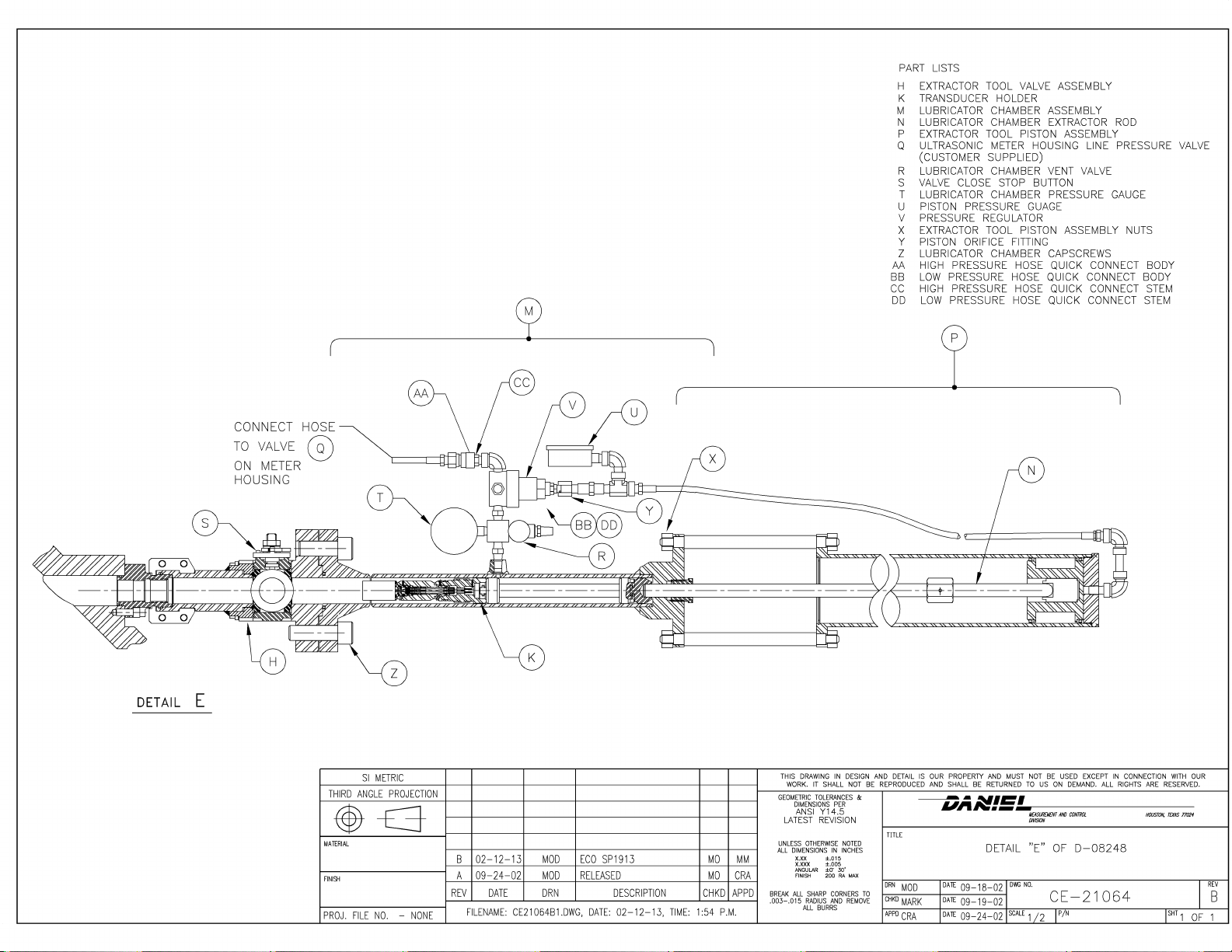
Page 63

Page 64

Page 65

Page 66

3-9000-744
Revision F
2013
This product is a core component of the PlantWeb digital plant architecture.
Emerson Process Management
Daniel Measurement and Control, Inc.
11100 Brittmoore Park Drive Houston, TX 77041
USA T +1 713-467-6000
F +1 713-827-4805
USA Toll Free 1 888-356-9001
Daniel Measurement Services, Inc.
T +1 713-827-6413
www.emerson.com
Europe: Stirling, Scotland, UK
T +44-1786-433400
Middle East Africa: Dubai, UAE
T +971-4-811-8100
Asia Pacific: Singapore
T +65-677-8211
© 2013 Daniel Measurement and Control, Inc., All rights reserved.
The Emerson logo is a trademark and service mark of Emerson Electric Co. Daniel
Measurement and Control, Inc., and Daniel Measurement Services, Inc., (Daniel) are
Emerson Process Management business units. The Daniel name and logo are trademarks
of Daniel Industries, Inc. The Senior, Junior, Simplex, MeterLink, SeniorSonic, JuniorSonic,
and DanPac are trademarks of Daniel Industries, Inc. All other trademarks are property of
their respective owners.
 Loading...