

Page 1

Instruction Manual
P/N 20001266, Rev. CB
October 2010
Micro Motion
®
Series 3000 MVD
Transmitters and Controllers
Configuration and Use Manual
Page 2

©2010 Micro Motion, Inc. All rights reserved. The Micro Motion and Emerson logos are trademarks and service marks of Emerson
Electric Co. Micro Motion, ELITE, MVD, ProLink, MVD Direct Connect, and PlantWeb are marks of one of the Emerson Process
Management family of companies. All other trademarks are property of their respective owners.
Page 3

Contents
Chapter 1 Before You Begin . . . . . . . . . . . . . . . . . . . . . . . . . . . . . . . . . . . . . 1
1.1 About this manual . . . . . . . . . . . . . . . . . . . . . . . . . . . . . . . . . . . . . . . . . . . . . . . . . . . . 1
1.2 Safety . . . . . . . . . . . . . . . . . . . . . . . . . . . . . . . . . . . . . . . . . . . . . . . . . . . . . . . . . . . . . 1
1.3 European installations . . . . . . . . . . . . . . . . . . . . . . . . . . . . . . . . . . . . . . . . . . . . . . . . . 2
1.4 Environmental standards compliance . . . . . . . . . . . . . . . . . . . . . . . . . . . . . . . . . . . . . 2
1.5 Terminology . . . . . . . . . . . . . . . . . . . . . . . . . . . . . . . . . . . . . . . . . . . . . . . . . . . . . . . . . 2
1.6 Communication tools. . . . . . . . . . . . . . . . . . . . . . . . . . . . . . . . . . . . . . . . . . . . . . . . . . 3
1.7 Using this manual . . . . . . . . . . . . . . . . . . . . . . . . . . . . . . . . . . . . . . . . . . . . . . . . . . . . 3
1.8 Other documentation. . . . . . . . . . . . . . . . . . . . . . . . . . . . . . . . . . . . . . . . . . . . . . . . . . 4
1.9 Micro Motion customer service . . . . . . . . . . . . . . . . . . . . . . . . . . . . . . . . . . . . . . . . . . 5
Chapter 2 Installation . . . . . . . . . . . . . . . . . . . . . . . . . . . . . . . . . . . . . . . . . 7
2.1 Overview . . . . . . . . . . . . . . . . . . . . . . . . . . . . . . . . . . . . . . . . . . . . . . . . . . . . . . . . . . . 7
2.2 Installation procedure . . . . . . . . . . . . . . . . . . . . . . . . . . . . . . . . . . . . . . . . . . . . . . . . . 7
2.3 Replacing an RFT9739 rack-mount transmitter . . . . . . . . . . . . . . . . . . . . . . . . . . . . . 7
2.4 Model 3350 or Model 3700 safety precautions . . . . . . . . . . . . . . . . . . . . . . . . . . . . . . 8
2.5 Environmental requirements . . . . . . . . . . . . . . . . . . . . . . . . . . . . . . . . . . . . . . . . . . . . 8
2.6 Ingress protection for Model 3300 controller . . . . . . . . . . . . . . . . . . . . . . . . . . . . . . . . 8
2.7 Frequency input cable length . . . . . . . . . . . . . . . . . . . . . . . . . . . . . . . . . . . . . . . . . . . 8
2.8 Model 3350 or Model 3700 display cover orientation (optional) . . . . . . . . . . . . . . . . . 9
2.9 Installing the remote core processor . . . . . . . . . . . . . . . . . . . . . . . . . . . . . . . . . . . . . 10
2.10 Sensor wiring . . . . . . . . . . . . . . . . . . . . . . . . . . . . . . . . . . . . . . . . . . . . . . . . . . . . . . 10
2.10.1 Cable types . . . . . . . . . . . . . . . . . . . . . . . . . . . . . . . . . . . . . . . . . . . . . . . 10
2.10.2 Cable glands in remote core processor with remote
transmitter installations . . . . . . . . . . . . . . . . . . . . . . . . . . . . . . . . . . . . . . 11
2.11 I/O wiring . . . . . . . . . . . . . . . . . . . . . . . . . . . . . . . . . . . . . . . . . . . . . . . . . . . . . . . . . 11
2.11.1 Terminals and terminal block locations . . . . . . . . . . . . . . . . . . . . . . . . . . 11
2.11.2 Grounding . . . . . . . . . . . . . . . . . . . . . . . . . . . . . . . . . . . . . . . . . . . . . . . . 13
2.11.3 Installing relays . . . . . . . . . . . . . . . . . . . . . . . . . . . . . . . . . . . . . . . . . . . . 13
2.12 Digital communications wiring. . . . . . . . . . . . . . . . . . . . . . . . . . . . . . . . . . . . . . . . . . 13
Chapter 3 Digital Communications Setup . . . . . . . . . . . . . . . . . . . . . . . . . . . 15
3.1 About this chapter . . . . . . . . . . . . . . . . . . . . . . . . . . . . . . . . . . . . . . . . . . . . . . . . . . . 15
3.2 Supported protocols . . . . . . . . . . . . . . . . . . . . . . . . . . . . . . . . . . . . . . . . . . . . . . . . . 15
3.2.1 Obtaining the components . . . . . . . . . . . . . . . . . . . . . . . . . . . . . . . . . . . . 15
3.2.2 RS-485 signal converter . . . . . . . . . . . . . . . . . . . . . . . . . . . . . . . . . . . . . 15
3.2.3 Bell 202 signal converter . . . . . . . . . . . . . . . . . . . . . . . . . . . . . . . . . . . . . 16
3.3 Setting up RS-485 communications . . . . . . . . . . . . . . . . . . . . . . . . . . . . . . . . . . . . . 16
3.4 Setting up Bell 202 communications . . . . . . . . . . . . . . . . . . . . . . . . . . . . . . . . . . . . . 19
Configuration and Use Manual i
Page 4

Contents
Chapter 4 Using the Display and Menu System . . . . . . . . . . . . . . . . . . . . . . . 25
4.1 About this chapter . . . . . . . . . . . . . . . . . . . . . . . . . . . . . . . . . . . . . . . . . . . . . . . . . . . 25
4.2 Startup display . . . . . . . . . . . . . . . . . . . . . . . . . . . . . . . . . . . . . . . . . . . . . . . . . . . . . 25
4.3 Menu systems. . . . . . . . . . . . . . . . . . . . . . . . . . . . . . . . . . . . . . . . . . . . . . . . . . . . . . 26
4.3.1 Accessing management functions. . . . . . . . . . . . . . . . . . . . . . . . . . . . . . 27
4.3.2 Shortcuts . . . . . . . . . . . . . . . . . . . . . . . . . . . . . . . . . . . . . . . . . . . . . . . . . 28
4.4 Using the function buttons . . . . . . . . . . . . . . . . . . . . . . . . . . . . . . . . . . . . . . . . . . . . 28
4.5 Using the cursor control buttons . . . . . . . . . . . . . . . . . . . . . . . . . . . . . . . . . . . . . . . . 30
4.5.1 Selecting from a list . . . . . . . . . . . . . . . . . . . . . . . . . . . . . . . . . . . . . . . . . 30
4.5.2 Changing a variable value . . . . . . . . . . . . . . . . . . . . . . . . . . . . . . . . . . . . 30
4.5.3 Cursor control example . . . . . . . . . . . . . . . . . . . . . . . . . . . . . . . . . . . . . . 30
4.5.4 Process monitor. . . . . . . . . . . . . . . . . . . . . . . . . . . . . . . . . . . . . . . . . . . . 30
4.6 Scientific notation . . . . . . . . . . . . . . . . . . . . . . . . . . . . . . . . . . . . . . . . . . . . . . . . . . . 30
Chapter 5 Configuring Security and Language . . . . . . . . . . . . . . . . . . . . . . . 33
5.1 About this chapter . . . . . . . . . . . . . . . . . . . . . . . . . . . . . . . . . . . . . . . . . . . . . . . . . . . 33
5.2 Security menu . . . . . . . . . . . . . . . . . . . . . . . . . . . . . . . . . . . . . . . . . . . . . . . . . . . . . . 33
5.3 Security . . . . . . . . . . . . . . . . . . . . . . . . . . . . . . . . . . . . . . . . . . . . . . . . . . . . . . . . . . . 34
5.3.1 Management menu access . . . . . . . . . . . . . . . . . . . . . . . . . . . . . . . . . . . 34
5.3.2 Write-protecting the device configuration . . . . . . . . . . . . . . . . . . . . . . . . 34
5.3.3 Controlling process totalizer and process inventory reset . . . . . . . . . . . . 35
5.4 Language menu . . . . . . . . . . . . . . . . . . . . . . . . . . . . . . . . . . . . . . . . . . . . . . . . . . . . 35
Chapter 6 Configuring System Data. . . . . . . . . . . . . . . . . . . . . . . . . . . . . . . 37
6.1 About this chapter . . . . . . . . . . . . . . . . . . . . . . . . . . . . . . . . . . . . . . . . . . . . . . . . . . . 37
6.2 System menu . . . . . . . . . . . . . . . . . . . . . . . . . . . . . . . . . . . . . . . . . . . . . . . . . . . . . . 37
6.3 System parameters . . . . . . . . . . . . . . . . . . . . . . . . . . . . . . . . . . . . . . . . . . . . . . . . . 38
6.3.1 Alarm severity . . . . . . . . . . . . . . . . . . . . . . . . . . . . . . . . . . . . . . . . . . . . . 38
Chapter 7 Configuring Inputs . . . . . . . . . . . . . . . . . . . . . . . . . . . . . . . . . . . 39
7.1 About this chapter . . . . . . . . . . . . . . . . . . . . . . . . . . . . . . . . . . . . . . . . . . . . . . . . . . . 39
7.2 Inputs menu . . . . . . . . . . . . . . . . . . . . . . . . . . . . . . . . . . . . . . . . . . . . . . . . . . . . . . . 39
7.3 Configuring the core processor parameters . . . . . . . . . . . . . . . . . . . . . . . . . . . . . . . 41
7.3.1 Enabling and disabling core processor inputs . . . . . . . . . . . . . . . . . . . . . 42
7.3.2 Configuring process variables . . . . . . . . . . . . . . . . . . . . . . . . . . . . . . . . . 42
7.3.3 Sensor calibration data . . . . . . . . . . . . . . . . . . . . . . . . . . . . . . . . . . . . . . 53
7.3.4 Sensor information . . . . . . . . . . . . . . . . . . . . . . . . . . . . . . . . . . . . . . . . . 56
7.3.5 Discrete inputs . . . . . . . . . . . . . . . . . . . . . . . . . . . . . . . . . . . . . . . . . . . . . 56
7.4 Configuring the frequency input . . . . . . . . . . . . . . . . . . . . . . . . . . . . . . . . . . . . . . . . 57
7.5 Configuring the discrete inputs . . . . . . . . . . . . . . . . . . . . . . . . . . . . . . . . . . . . . . . . . 58
7.6 Configuring the external inputs . . . . . . . . . . . . . . . . . . . . . . . . . . . . . . . . . . . . . . . . . 59
Chapter 8 Configuring Outputs . . . . . . . . . . . . . . . . . . . . . . . . . . . . . . . . . . 61
8.1 About this chapter . . . . . . . . . . . . . . . . . . . . . . . . . . . . . . . . . . . . . . . . . . . . . . . . . . . 61
8.2 Outputs menu . . . . . . . . . . . . . . . . . . . . . . . . . . . . . . . . . . . . . . . . . . . . . . . . . . . . . . 61
8.3 Configuring the discrete outputs . . . . . . . . . . . . . . . . . . . . . . . . . . . . . . . . . . . . . . . . 63
8.3.1 Polarity. . . . . . . . . . . . . . . . . . . . . . . . . . . . . . . . . . . . . . . . . . . . . . . . . . . 63
8.3.2 Source variable assignment . . . . . . . . . . . . . . . . . . . . . . . . . . . . . . . . . . 64
8.3.3 Fault indication. . . . . . . . . . . . . . . . . . . . . . . . . . . . . . . . . . . . . . . . . . . . . 65
ii Micro Motion® Series 3000 MVD Transmitters and Controllers
Page 5

Contents
8.4 Configuring the milliamp outputs. . . . . . . . . . . . . . . . . . . . . . . . . . . . . . . . . . . . . . . . 66
8.4.1 Milliamp output. . . . . . . . . . . . . . . . . . . . . . . . . . . . . . . . . . . . . . . . . . . . . 66
8.4.2 Fault indication. . . . . . . . . . . . . . . . . . . . . . . . . . . . . . . . . . . . . . . . . . . . . 66
8.4.3 Process variable . . . . . . . . . . . . . . . . . . . . . . . . . . . . . . . . . . . . . . . . . . . 67
8.4.4 Calibration span . . . . . . . . . . . . . . . . . . . . . . . . . . . . . . . . . . . . . . . . . . . . 67
8.5 Configuring the frequency output . . . . . . . . . . . . . . . . . . . . . . . . . . . . . . . . . . . . . . . 70
8.5.1 Frequency = flow . . . . . . . . . . . . . . . . . . . . . . . . . . . . . . . . . . . . . . . . . . . 71
8.5.2 Maximum pulse width . . . . . . . . . . . . . . . . . . . . . . . . . . . . . . . . . . . . . . . 72
Chapter 9 Configuring the Petroleum Measurement Application . . . . . . . . . . . 75
9.1 About this chapter . . . . . . . . . . . . . . . . . . . . . . . . . . . . . . . . . . . . . . . . . . . . . . . . . . . 75
9.2 API menu . . . . . . . . . . . . . . . . . . . . . . . . . . . . . . . . . . . . . . . . . . . . . . . . . . . . . . . . . 75
9.3 About petroleum measurement. . . . . . . . . . . . . . . . . . . . . . . . . . . . . . . . . . . . . . . . . 76
9.3.1 Definitions . . . . . . . . . . . . . . . . . . . . . . . . . . . . . . . . . . . . . . . . . . . . . . . . 76
9.3.2 CTL derivation methods. . . . . . . . . . . . . . . . . . . . . . . . . . . . . . . . . . . . . . 76
9.4 Configuring petroleum measurement parameters. . . . . . . . . . . . . . . . . . . . . . . . . . . 76
9.4.1 Reference tables . . . . . . . . . . . . . . . . . . . . . . . . . . . . . . . . . . . . . . . . . . . 77
9.4.2 Temperature data . . . . . . . . . . . . . . . . . . . . . . . . . . . . . . . . . . . . . . . . . . . 78
Chapter 10 Configuring Discrete Events . . . . . . . . . . . . . . . . . . . . . . . . . . . . . 79
10.1 About this chapter . . . . . . . . . . . . . . . . . . . . . . . . . . . . . . . . . . . . . . . . . . . . . . . . . . . 79
10.2 Discrete events menu . . . . . . . . . . . . . . . . . . . . . . . . . . . . . . . . . . . . . . . . . . . . . . . . 79
10.3 About discrete events . . . . . . . . . . . . . . . . . . . . . . . . . . . . . . . . . . . . . . . . . . . . . . . . 79
10.4 Discrete event configuration procedure. . . . . . . . . . . . . . . . . . . . . . . . . . . . . . . . . . . 80
Chapter 11 Configuring the Discrete Batch Application . . . . . . . . . . . . . . . . . . 83
11.1 About this chapter . . . . . . . . . . . . . . . . . . . . . . . . . . . . . . . . . . . . . . . . . . . . . . . . . . . 83
11.2 Discrete batch menu . . . . . . . . . . . . . . . . . . . . . . . . . . . . . . . . . . . . . . . . . . . . . . . . . 83
11.3 Batching configuration overview . . . . . . . . . . . . . . . . . . . . . . . . . . . . . . . . . . . . . . . . 84
11.4 Flow source. . . . . . . . . . . . . . . . . . . . . . . . . . . . . . . . . . . . . . . . . . . . . . . . . . . . . . . . 85
11.5 Control options . . . . . . . . . . . . . . . . . . . . . . . . . . . . . . . . . . . . . . . . . . . . . . . . . . . . . 86
11.5.1 One-stage versus two-stage batching . . . . . . . . . . . . . . . . . . . . . . . . . . . 88
11.6 Configure presets . . . . . . . . . . . . . . . . . . . . . . . . . . . . . . . . . . . . . . . . . . . . . . . . . . . 88
11.6.1 Batch preset examples . . . . . . . . . . . . . . . . . . . . . . . . . . . . . . . . . . . . . . 89
11.7 Batch control methods . . . . . . . . . . . . . . . . . . . . . . . . . . . . . . . . . . . . . . . . . . . . . . . 90
11.7.1 Special cases in batch control . . . . . . . . . . . . . . . . . . . . . . . . . . . . . . . . . 92
Chapter 12 Configuring the Process Monitor. . . . . . . . . . . . . . . . . . . . . . . . . . 93
12.1 About this chapter . . . . . . . . . . . . . . . . . . . . . . . . . . . . . . . . . . . . . . . . . . . . . . . . . . . 93
12.2 Monitoring menu . . . . . . . . . . . . . . . . . . . . . . . . . . . . . . . . . . . . . . . . . . . . . . . . . . . . 93
12.3 Process monitor screens. . . . . . . . . . . . . . . . . . . . . . . . . . . . . . . . . . . . . . . . . . . . . . 94
12.4 Process monitor variables. . . . . . . . . . . . . . . . . . . . . . . . . . . . . . . . . . . . . . . . . . . . . 94
12.5 Update period . . . . . . . . . . . . . . . . . . . . . . . . . . . . . . . . . . . . . . . . . . . . . . . . . . . . . . 95
Configuration and Use Manual iii
Page 6

Contents
Chapter 13 Configuring Digital Communications. . . . . . . . . . . . . . . . . . . . . . . 97
13.1 About this chapter. . . . . . . . . . . . . . . . . . . . . . . . . . . . . . . . . . . . . . . . . . . . . . . . . . . 97
13.2 Digital communication menu. . . . . . . . . . . . . . . . . . . . . . . . . . . . . . . . . . . . . . . . . . . 97
13.3 Configuring RS-485 parameters . . . . . . . . . . . . . . . . . . . . . . . . . . . . . . . . . . . . . . . . 99
13.3.1 Configuring HART, Modbus RTU, or Modbus ASCII protocol . . . . . . . . . 99
13.3.2 Configuring printer protocol . . . . . . . . . . . . . . . . . . . . . . . . . . . . . . . . . . 101
13.4 Configuring Bell 202 parameters . . . . . . . . . . . . . . . . . . . . . . . . . . . . . . . . . . . . . . 102
13.4.1 Loop current mode . . . . . . . . . . . . . . . . . . . . . . . . . . . . . . . . . . . . . . . . 103
13.4.2 Burst mode . . . . . . . . . . . . . . . . . . . . . . . . . . . . . . . . . . . . . . . . . . . . . . 103
13.4.3 Communicating with a remote device . . . . . . . . . . . . . . . . . . . . . . . . . . 104
13.5 Configuring device parameters . . . . . . . . . . . . . . . . . . . . . . . . . . . . . . . . . . . . . . . . 104
Chapter 14 Configuring Custody Transfer . . . . . . . . . . . . . . . . . . . . . . . . . . . 105
14.1 About this chapter. . . . . . . . . . . . . . . . . . . . . . . . . . . . . . . . . . . . . . . . . . . . . . . . . . 105
14.2 About custody transfer . . . . . . . . . . . . . . . . . . . . . . . . . . . . . . . . . . . . . . . . . . . . . . 105
14.3 Configuration options . . . . . . . . . . . . . . . . . . . . . . . . . . . . . . . . . . . . . . . . . . . . . . . 106
14.4 Configuring custody transfer (NTEP) . . . . . . . . . . . . . . . . . . . . . . . . . . . . . . . . . . . 107
14.5 Configuring custody transfer (OIML) and custody transfer (OIML/batch) . . . . . . . . 108
14.6 Setting the security switch . . . . . . . . . . . . . . . . . . . . . . . . . . . . . . . . . . . . . . . . . . . 111
14.6.1 Panel-mount devices . . . . . . . . . . . . . . . . . . . . . . . . . . . . . . . . . . . . . . . 111
14.6.2 Rack-mount devices . . . . . . . . . . . . . . . . . . . . . . . . . . . . . . . . . . . . . . . 112
14.6.3 Field-mount devices. . . . . . . . . . . . . . . . . . . . . . . . . . . . . . . . . . . . . . . . 113
14.7 Installing the weights and measures seal . . . . . . . . . . . . . . . . . . . . . . . . . . . . . . . . 115
Chapter 15 Ticket Formatting and Printing . . . . . . . . . . . . . . . . . . . . . . . . . . 117
15.1 About this chapter. . . . . . . . . . . . . . . . . . . . . . . . . . . . . . . . . . . . . . . . . . . . . . . . . . 117
15.2 Ticket overview . . . . . . . . . . . . . . . . . . . . . . . . . . . . . . . . . . . . . . . . . . . . . . . . . . . . 117
15.3 Standard tickets . . . . . . . . . . . . . . . . . . . . . . . . . . . . . . . . . . . . . . . . . . . . . . . . . . . 119
15.3.1 Formatting . . . . . . . . . . . . . . . . . . . . . . . . . . . . . . . . . . . . . . . . . . . . . . . 119
15.3.2 Printing . . . . . . . . . . . . . . . . . . . . . . . . . . . . . . . . . . . . . . . . . . . . . . . . . 120
15.4 Batch tickets . . . . . . . . . . . . . . . . . . . . . . . . . . . . . . . . . . . . . . . . . . . . . . . . . . . . . . 121
15.4.1 Formatting . . . . . . . . . . . . . . . . . . . . . . . . . . . . . . . . . . . . . . . . . . . . . . . 121
15.4.2 Printing . . . . . . . . . . . . . . . . . . . . . . . . . . . . . . . . . . . . . . . . . . . . . . . . . 122
15.5 Batch (NTEP) tickets. . . . . . . . . . . . . . . . . . . . . . . . . . . . . . . . . . . . . . . . . . . . . . . . 123
15.5.1 Formatting . . . . . . . . . . . . . . . . . . . . . . . . . . . . . . . . . . . . . . . . . . . . . . . 123
15.5.2 Printing . . . . . . . . . . . . . . . . . . . . . . . . . . . . . . . . . . . . . . . . . . . . . . . . . 124
15.6 Transfer (OIML) tickets . . . . . . . . . . . . . . . . . . . . . . . . . . . . . . . . . . . . . . . . . . . . . . 125
15.6.1 Formatting . . . . . . . . . . . . . . . . . . . . . . . . . . . . . . . . . . . . . . . . . . . . . . . 125
15.6.2 Printing . . . . . . . . . . . . . . . . . . . . . . . . . . . . . . . . . . . . . . . . . . . . . . . . . 127
15.7 Batch (OIML) tickets . . . . . . . . . . . . . . . . . . . . . . . . . . . . . . . . . . . . . . . . . . . . . . . . 129
15.7.1 Formatting . . . . . . . . . . . . . . . . . . . . . . . . . . . . . . . . . . . . . . . . . . . . . . . 129
15.7.2 Printing . . . . . . . . . . . . . . . . . . . . . . . . . . . . . . . . . . . . . . . . . . . . . . . . . 131
Chapter 16 Startup Procedures. . . . . . . . . . . . . . . . . . . . . . . . . . . . . . . . . . 133
16.1 About this chapter. . . . . . . . . . . . . . . . . . . . . . . . . . . . . . . . . . . . . . . . . . . . . . . . . . 133
16.2 Applying power . . . . . . . . . . . . . . . . . . . . . . . . . . . . . . . . . . . . . . . . . . . . . . . . . . . . 133
16.2.1 Communication methods after power-up . . . . . . . . . . . . . . . . . . . . . . . . 134
iv Micro Motion® Series 3000 MVD Transmitters and Controllers
Page 7

Contents
16.3 Sensor zero. . . . . . . . . . . . . . . . . . . . . . . . . . . . . . . . . . . . . . . . . . . . . . . . . . . . . . . 134
16.3.1 Zero failure and restoring zero values . . . . . . . . . . . . . . . . . . . . . . . . . . 135
16.3.2 Preparing for sensor zero calibration . . . . . . . . . . . . . . . . . . . . . . . . . . . 135
16.3.3 Performing the sensor zero calibration . . . . . . . . . . . . . . . . . . . . . . . . . 135
16.3.4 Diagnosing sensor zero failure. . . . . . . . . . . . . . . . . . . . . . . . . . . . . . . . 138
16.4 Testing the inputs and outputs . . . . . . . . . . . . . . . . . . . . . . . . . . . . . . . . . . . . . . . . 138
16.4.1 Reading and testing the discrete inputs. . . . . . . . . . . . . . . . . . . . . . . . . 139
16.4.2 Reading and testing the frequency input . . . . . . . . . . . . . . . . . . . . . . . . 139
16.4.3 Reading and testing the pressure and external temperature . . . . . . . . . 139
16.4.4 Setting and testing outputs . . . . . . . . . . . . . . . . . . . . . . . . . . . . . . . . . . 139
16.5 Milliamp output trim. . . . . . . . . . . . . . . . . . . . . . . . . . . . . . . . . . . . . . . . . . . . . . . . . 140
Chapter 17 Operation Mode . . . . . . . . . . . . . . . . . . . . . . . . . . . . . . . . . . . . 143
17.1 About this chapter . . . . . . . . . . . . . . . . . . . . . . . . . . . . . . . . . . . . . . . . . . . . . . . . . . 143
17.2 Startup and display test. . . . . . . . . . . . . . . . . . . . . . . . . . . . . . . . . . . . . . . . . . . . . . 143
17.3 Initial startup . . . . . . . . . . . . . . . . . . . . . . . . . . . . . . . . . . . . . . . . . . . . . . . . . . . . . . 143
17.4 Process monitor operation mode . . . . . . . . . . . . . . . . . . . . . . . . . . . . . . . . . . . . . . 144
17.5 Using the View menu . . . . . . . . . . . . . . . . . . . . . . . . . . . . . . . . . . . . . . . . . . . . . . . 145
17.5.1 Active alarm log . . . . . . . . . . . . . . . . . . . . . . . . . . . . . . . . . . . . . . . . . . . 146
17.5.2 Process monitoring . . . . . . . . . . . . . . . . . . . . . . . . . . . . . . . . . . . . . . . . 147
17.5.3 Preset selections . . . . . . . . . . . . . . . . . . . . . . . . . . . . . . . . . . . . . . . . . . 147
17.5.4 Batch inventory . . . . . . . . . . . . . . . . . . . . . . . . . . . . . . . . . . . . . . . . . . . 147
17.5.5 Process totalizers and inventories . . . . . . . . . . . . . . . . . . . . . . . . . . . . . 147
17.5.6 Diagnostic monitor . . . . . . . . . . . . . . . . . . . . . . . . . . . . . . . . . . . . . . . . . 148
17.5.7 LCD options . . . . . . . . . . . . . . . . . . . . . . . . . . . . . . . . . . . . . . . . . . . . . . 148
17.5.8 Density curves . . . . . . . . . . . . . . . . . . . . . . . . . . . . . . . . . . . . . . . . . . . . 148
17.5.9 Applications list . . . . . . . . . . . . . . . . . . . . . . . . . . . . . . . . . . . . . . . . . . . 148
Chapter 18 Operation Mode – Batch . . . . . . . . . . . . . . . . . . . . . . . . . . . . . . 149
18.1 About this chapter . . . . . . . . . . . . . . . . . . . . . . . . . . . . . . . . . . . . . . . . . . . . . . . . . . 149
18.2 About discrete batching. . . . . . . . . . . . . . . . . . . . . . . . . . . . . . . . . . . . . . . . . . . . . . 149
18.3 Batch process screen . . . . . . . . . . . . . . . . . . . . . . . . . . . . . . . . . . . . . . . . . . . . . . . 150
18.3.1 Function buttons . . . . . . . . . . . . . . . . . . . . . . . . . . . . . . . . . . . . . . . . . . 151
18.3.2 Cursor control buttons . . . . . . . . . . . . . . . . . . . . . . . . . . . . . . . . . . . . . . 153
18.4 Batch processing sequences . . . . . . . . . . . . . . . . . . . . . . . . . . . . . . . . . . . . . . . . . 153
18.5 Special cases in batch processing . . . . . . . . . . . . . . . . . . . . . . . . . . . . . . . . . . . . . 157
18.5.1 Cleaning/purging the tubes . . . . . . . . . . . . . . . . . . . . . . . . . . . . . . . . . . 157
18.5.2 Ending a batch while flow is present . . . . . . . . . . . . . . . . . . . . . . . . . . . 157
18.6 Batch AOC calibration . . . . . . . . . . . . . . . . . . . . . . . . . . . . . . . . . . . . . . . . . . . . . . . 157
Chapter 19 Operation Mode – Custody Transfer. . . . . . . . . . . . . . . . . . . . . . . 159
19.1 About this chapter . . . . . . . . . . . . . . . . . . . . . . . . . . . . . . . . . . . . . . . . . . . . . . . . . . 159
19.2 Identifying a security breach . . . . . . . . . . . . . . . . . . . . . . . . . . . . . . . . . . . . . . . . . . 159
19.3 Secured versus unsecured . . . . . . . . . . . . . . . . . . . . . . . . . . . . . . . . . . . . . . . . . . . 159
19.4 Custody transfer (NTEP). . . . . . . . . . . . . . . . . . . . . . . . . . . . . . . . . . . . . . . . . . . . . 163
19.4.1 BOL number. . . . . . . . . . . . . . . . . . . . . . . . . . . . . . . . . . . . . . . . . . . . . . 163
19.4.2 Executing a custody transfer (NTEP) transaction . . . . . . . . . . . . . . . . . 163
19.4.3 Batch (NTEP) tickets and ticket printing. . . . . . . . . . . . . . . . . . . . . . . . . 163
19.4.4 General use of Series 3000 device . . . . . . . . . . . . . . . . . . . . . . . . . . . . 164
19.4.5 Inventories . . . . . . . . . . . . . . . . . . . . . . . . . . . . . . . . . . . . . . . . . . . . . . . 164
Configuration and Use Manual v
Page 8

Contents
19.5 Custody transfer (OIML) and custody transfer (OIML/batch) . . . . . . . . . . . . . . . . . 164
19.5.1 BOL numbers. . . . . . . . . . . . . . . . . . . . . . . . . . . . . . . . . . . . . . . . . . . . . 164
19.5.2 Executing a custody transfer (OIML) transaction. . . . . . . . . . . . . . . . . . 164
19.5.3 Executing a custody transfer (OIML/batch) transaction . . . . . . . . . . . . . 165
19.5.4 Transfer (OIML) and batch (OIML) tickets and ticket printing. . . . . . . . . 166
19.5.5 Transfer log . . . . . . . . . . . . . . . . . . . . . . . . . . . . . . . . . . . . . . . . . . . . . . 167
19.5.6 General use of Series 3000 device . . . . . . . . . . . . . . . . . . . . . . . . . . . . 168
19.6 Clearing a security breach . . . . . . . . . . . . . . . . . . . . . . . . . . . . . . . . . . . . . . . . . . . 170
19.7 Reconfiguring the Series 3000 device . . . . . . . . . . . . . . . . . . . . . . . . . . . . . . . . . . 170
19.8 Audit trail . . . . . . . . . . . . . . . . . . . . . . . . . . . . . . . . . . . . . . . . . . . . . . . . . . . . . . . . . 170
19.8.1 Using the audit trail . . . . . . . . . . . . . . . . . . . . . . . . . . . . . . . . . . . . . . . . 171
Chapter 20 Using Totalizers and Inventories. . . . . . . . . . . . . . . . . . . . . . . . . 173
20.1 About this chapter. . . . . . . . . . . . . . . . . . . . . . . . . . . . . . . . . . . . . . . . . . . . . . . . . . 173
20.2 Overview . . . . . . . . . . . . . . . . . . . . . . . . . . . . . . . . . . . . . . . . . . . . . . . . . . . . . . . . . 173
20.3 Totalizer management. . . . . . . . . . . . . . . . . . . . . . . . . . . . . . . . . . . . . . . . . . . . . . . 174
20.4 Process totalizers . . . . . . . . . . . . . . . . . . . . . . . . . . . . . . . . . . . . . . . . . . . . . . . . . . 176
20.5 Process inventories. . . . . . . . . . . . . . . . . . . . . . . . . . . . . . . . . . . . . . . . . . . . . . . . . 176
20.6 Batch inventories . . . . . . . . . . . . . . . . . . . . . . . . . . . . . . . . . . . . . . . . . . . . . . . . . . 176
Chapter 21 Measurement Performance . . . . . . . . . . . . . . . . . . . . . . . . . . . . 179
21.1 Overview . . . . . . . . . . . . . . . . . . . . . . . . . . . . . . . . . . . . . . . . . . . . . . . . . . . . . . . . . 179
21.2 Meter verification, meter validation, and calibration . . . . . . . . . . . . . . . . . . . . . . . . 179
21.2.1 Meter verification . . . . . . . . . . . . . . . . . . . . . . . . . . . . . . . . . . . . . . . . . . 180
21.2.2 Meter validation and meter factors . . . . . . . . . . . . . . . . . . . . . . . . . . . . 181
21.2.3 Calibration . . . . . . . . . . . . . . . . . . . . . . . . . . . . . . . . . . . . . . . . . . . . . . . 181
21.2.4 Comparison and recommendations. . . . . . . . . . . . . . . . . . . . . . . . . . . . 182
21.3 Performing meter verification . . . . . . . . . . . . . . . . . . . . . . . . . . . . . . . . . . . . . . . . . 183
21.3.1 Preparing for the meter verification test. . . . . . . . . . . . . . . . . . . . . . . . . 183
21.3.2 Running the meter verification test, original version . . . . . . . . . . . . . . . 184
21.3.3 Running Smart Meter Verification . . . . . . . . . . . . . . . . . . . . . . . . . . . . . 186
21.3.4 Reading and interpreting meter verification test results . . . . . . . . . . . . 190
21.3.5 Setting up automatic or remote execution of the
meter verification test . . . . . . . . . . . . . . . . . . . . . . . . . . . . . . . . . . . . . . 195
21.4 Performing meter validation . . . . . . . . . . . . . . . . . . . . . . . . . . . . . . . . . . . . . . . . . . 196
21.5 Performing density calibration. . . . . . . . . . . . . . . . . . . . . . . . . . . . . . . . . . . . . . . . . 197
21.5.1 Preparing for density calibration . . . . . . . . . . . . . . . . . . . . . . . . . . . . . . 197
21.5.2 Density calibration procedures . . . . . . . . . . . . . . . . . . . . . . . . . . . . . . . 199
21.6 Performing temperature calibration. . . . . . . . . . . . . . . . . . . . . . . . . . . . . . . . . . . . . 201
Chapter 22 Diagnostics and Troubleshooting . . . . . . . . . . . . . . . . . . . . . . . . 203
22.1 About this chapter. . . . . . . . . . . . . . . . . . . . . . . . . . . . . . . . . . . . . . . . . . . . . . . . . . 203
22.2 Checking process variables . . . . . . . . . . . . . . . . . . . . . . . . . . . . . . . . . . . . . . . . . . 203
22.3 Meter fingerprinting. . . . . . . . . . . . . . . . . . . . . . . . . . . . . . . . . . . . . . . . . . . . . . . . . 206
22.4 Sensor simulation mode . . . . . . . . . . . . . . . . . . . . . . . . . . . . . . . . . . . . . . . . . . . . . 207
22.5 Updates, upgrades, and master resets. . . . . . . . . . . . . . . . . . . . . . . . . . . . . . . . . . 208
22.6 Alarm types and handling . . . . . . . . . . . . . . . . . . . . . . . . . . . . . . . . . . . . . . . . . . . . 208
22.6.1 Alarm severity . . . . . . . . . . . . . . . . . . . . . . . . . . . . . . . . . . . . . . . . . . . . 208
22.6.2 Fault timeout . . . . . . . . . . . . . . . . . . . . . . . . . . . . . . . . . . . . . . . . . . . . . 209
22.6.3 Alarm categories . . . . . . . . . . . . . . . . . . . . . . . . . . . . . . . . . . . . . . . . . . 209
22.6.4 Alarm occurrences and logs . . . . . . . . . . . . . . . . . . . . . . . . . . . . . . . . . 209
22.6.5 Help system . . . . . . . . . . . . . . . . . . . . . . . . . . . . . . . . . . . . . . . . . . . . . . 211
vi Micro Motion® Series 3000 MVD Transmitters and Controllers
Page 9

Contents
22.7 Alarm listings by category . . . . . . . . . . . . . . . . . . . . . . . . . . . . . . . . . . . . . . . . . . . . 212
22.7.1 Electronics alarms . . . . . . . . . . . . . . . . . . . . . . . . . . . . . . . . . . . . . . . . . 212
22.7.2 Sensor alarms . . . . . . . . . . . . . . . . . . . . . . . . . . . . . . . . . . . . . . . . . . . . 215
22.7.3 Process alarms . . . . . . . . . . . . . . . . . . . . . . . . . . . . . . . . . . . . . . . . . . . 216
22.7.4 Configuration alarms . . . . . . . . . . . . . . . . . . . . . . . . . . . . . . . . . . . . . . . 222
22.8 Restoring a working configuration. . . . . . . . . . . . . . . . . . . . . . . . . . . . . . . . . . . . . . 224
22.9 A009/A026 alarms on Model 3300 or Model 3500 panel-mount. . . . . . . . . . . . . . . 224
22.10 I/O problems . . . . . . . . . . . . . . . . . . . . . . . . . . . . . . . . . . . . . . . . . . . . . . . . . . . . . . 225
22.11 Diagnosing wiring problems . . . . . . . . . . . . . . . . . . . . . . . . . . . . . . . . . . . . . . . . . . 227
22.11.1 Checking the power supply wiring . . . . . . . . . . . . . . . . . . . . . . . . . . . . . 227
22.11.2 Checking the sensor-to-transmitter wiring . . . . . . . . . . . . . . . . . . . . . . . 228
22.11.3 Checking grounding . . . . . . . . . . . . . . . . . . . . . . . . . . . . . . . . . . . . . . . . 228
22.11.4 Checking the HART communication loop . . . . . . . . . . . . . . . . . . . . . . . 228
22.11.5 Checking for RF interference . . . . . . . . . . . . . . . . . . . . . . . . . . . . . . . . . 228
22.11.6 Checking the output wiring and receiving device. . . . . . . . . . . . . . . . . . 229
22.11.7 Checking the Loop Current Mode parameter. . . . . . . . . . . . . . . . . . . . . 229
22.12 Checking the sensor tubes . . . . . . . . . . . . . . . . . . . . . . . . . . . . . . . . . . . . . . . . . . . 229
22.13 Checking the flow measurement unit . . . . . . . . . . . . . . . . . . . . . . . . . . . . . . . . . . . 229
22.14 Checking the calibration span . . . . . . . . . . . . . . . . . . . . . . . . . . . . . . . . . . . . . . . . . 229
22.15 Checking the frequency output scale and method . . . . . . . . . . . . . . . . . . . . . . . . . 229
22.16 Checking the characterization . . . . . . . . . . . . . . . . . . . . . . . . . . . . . . . . . . . . . . . . . 229
22.17 Checking the calibration . . . . . . . . . . . . . . . . . . . . . . . . . . . . . . . . . . . . . . . . . . . . . 230
22.18 Checking the test points . . . . . . . . . . . . . . . . . . . . . . . . . . . . . . . . . . . . . . . . . . . . . 230
22.18.1 Obtaining the test points . . . . . . . . . . . . . . . . . . . . . . . . . . . . . . . . . . . . 230
22.18.2 Evaluating the test points . . . . . . . . . . . . . . . . . . . . . . . . . . . . . . . . . . . . 230
22.18.3 Excessive drive gain . . . . . . . . . . . . . . . . . . . . . . . . . . . . . . . . . . . . . . . 231
22.18.4 Erratic drive gain . . . . . . . . . . . . . . . . . . . . . . . . . . . . . . . . . . . . . . . . . . 231
22.18.5 Low pickoff voltage. . . . . . . . . . . . . . . . . . . . . . . . . . . . . . . . . . . . . . . . . 232
22.19 Checking the core processor . . . . . . . . . . . . . . . . . . . . . . . . . . . . . . . . . . . . . . . . . 232
22.19.1 Checking the core processor LED . . . . . . . . . . . . . . . . . . . . . . . . . . . . . 232
22.19.2 Core processor resistance test (standard core processor only) . . . . . . 234
22.20 Checking sensor coils and RTD . . . . . . . . . . . . . . . . . . . . . . . . . . . . . . . . . . . . . . . 235
22.20.1 Remote core processor with remote transmitter installation . . . . . . . . . 235
22.20.2 4-wire remote installation . . . . . . . . . . . . . . . . . . . . . . . . . . . . . . . . . . . . 236
Appendix A Specifications – Model 3300 and Model 3500. . . . . . . . . . . . . . . . 241
A.1 Housing and mounting . . . . . . . . . . . . . . . . . . . . . . . . . . . . . . . . . . . . . . . . . . . . . . 241
A.1.1 Panel-mount. . . . . . . . . . . . . . . . . . . . . . . . . . . . . . . . . . . . . . . . . . . . . . 241
A.1.2 Rack-mount . . . . . . . . . . . . . . . . . . . . . . . . . . . . . . . . . . . . . . . . . . . . . . 241
A.2 Interface/display . . . . . . . . . . . . . . . . . . . . . . . . . . . . . . . . . . . . . . . . . . . . . . . . . . . 241
A.3 Weight . . . . . . . . . . . . . . . . . . . . . . . . . . . . . . . . . . . . . . . . . . . . . . . . . . . . . . . . . . . 241
A.4 Dimensions . . . . . . . . . . . . . . . . . . . . . . . . . . . . . . . . . . . . . . . . . . . . . . . . . . . . . . . 241
A.5 Electrical connections . . . . . . . . . . . . . . . . . . . . . . . . . . . . . . . . . . . . . . . . . . . . . . . 246
A.5.1 Panel-mount. . . . . . . . . . . . . . . . . . . . . . . . . . . . . . . . . . . . . . . . . . . . . . 246
A.5.2 Rack-mount . . . . . . . . . . . . . . . . . . . . . . . . . . . . . . . . . . . . . . . . . . . . . . 246
A.6 Inputs and outputs. . . . . . . . . . . . . . . . . . . . . . . . . . . . . . . . . . . . . . . . . . . . . . . . . . 246
A.6.1 Intrinsically safe input signals . . . . . . . . . . . . . . . . . . . . . . . . . . . . . . . . 246
A.6.2 Non-intrinsically safe input signals . . . . . . . . . . . . . . . . . . . . . . . . . . . . . 246
A.6.3 Non-intrinsically safe output signals. . . . . . . . . . . . . . . . . . . . . . . . . . . . 247
A.6.4 Digital communications . . . . . . . . . . . . . . . . . . . . . . . . . . . . . . . . . . . . . 248
A.7 Power supply options . . . . . . . . . . . . . . . . . . . . . . . . . . . . . . . . . . . . . . . . . . . . . . . 248
A.7.1 Model 3300 controller . . . . . . . . . . . . . . . . . . . . . . . . . . . . . . . . . . . . . . 248
A.7.2 Model 3500 transmitter . . . . . . . . . . . . . . . . . . . . . . . . . . . . . . . . . . . . . 248
A.8 Environmental limits . . . . . . . . . . . . . . . . . . . . . . . . . . . . . . . . . . . . . . . . . . . . . . . . 249
Configuration and Use Manual vii
Page 10

Contents
A.9 Environmental effects . . . . . . . . . . . . . . . . . . . . . . . . . . . . . . . . . . . . . . . . . . . . . . . 249
A.10 Hazardous area classifications . . . . . . . . . . . . . . . . . . . . . . . . . . . . . . . . . . . . . . . . 249
A.10.1 ATEX . . . . . . . . . . . . . . . . . . . . . . . . . . . . . . . . . . . . . . . . . . . . . . . . . . . 249
A.10.2 UL and CSA. . . . . . . . . . . . . . . . . . . . . . . . . . . . . . . . . . . . . . . . . . . . . . 249
A.11 Performance specifications . . . . . . . . . . . . . . . . . . . . . . . . . . . . . . . . . . . . . . . . . . . 249
A.12 Cleaning instructions . . . . . . . . . . . . . . . . . . . . . . . . . . . . . . . . . . . . . . . . . . . . . . . 249
Appendix B Specifications – Model 3350 and Model 3700 . . . . . . . . . . . . . . . 251
B.1 Compartmentalized housing . . . . . . . . . . . . . . . . . . . . . . . . . . . . . . . . . . . . . . . . . . 251
B.2 Interface/display . . . . . . . . . . . . . . . . . . . . . . . . . . . . . . . . . . . . . . . . . . . . . . . . . . . 251
B.3 Weight. . . . . . . . . . . . . . . . . . . . . . . . . . . . . . . . . . . . . . . . . . . . . . . . . . . . . . . . . . . 251
B.4 Dimensions . . . . . . . . . . . . . . . . . . . . . . . . . . . . . . . . . . . . . . . . . . . . . . . . . . . . . . . 251
B.5 Electrical connections . . . . . . . . . . . . . . . . . . . . . . . . . . . . . . . . . . . . . . . . . . . . . . . 255
B.6 Inputs and outputs . . . . . . . . . . . . . . . . . . . . . . . . . . . . . . . . . . . . . . . . . . . . . . . . . 255
B.6.1 Intrinsically safe input signals . . . . . . . . . . . . . . . . . . . . . . . . . . . . . . . . 255
B.6.2 Non-intrinsically safe input signals. . . . . . . . . . . . . . . . . . . . . . . . . . . . . 255
B.6.3 Non-intrinsically safe output signals . . . . . . . . . . . . . . . . . . . . . . . . . . . 255
B.6.4 Digital communications . . . . . . . . . . . . . . . . . . . . . . . . . . . . . . . . . . . . . 256
B.7 Power supply options . . . . . . . . . . . . . . . . . . . . . . . . . . . . . . . . . . . . . . . . . . . . . . . 257
B.8 Environmental limits . . . . . . . . . . . . . . . . . . . . . . . . . . . . . . . . . . . . . . . . . . . . . . . . 257
B.9 Environmental effects . . . . . . . . . . . . . . . . . . . . . . . . . . . . . . . . . . . . . . . . . . . . . . . 257
B.10 Hazardous area classifications . . . . . . . . . . . . . . . . . . . . . . . . . . . . . . . . . . . . . . . . 257
B.10.1 ATEX . . . . . . . . . . . . . . . . . . . . . . . . . . . . . . . . . . . . . . . . . . . . . . . . . . . 257
B.10.2 UL and CSA. . . . . . . . . . . . . . . . . . . . . . . . . . . . . . . . . . . . . . . . . . . . . . 257
B.11 Performance specifications . . . . . . . . . . . . . . . . . . . . . . . . . . . . . . . . . . . . . . . . . . . 258
B.12 Cleaning instructions . . . . . . . . . . . . . . . . . . . . . . . . . . . . . . . . . . . . . . . . . . . . . . . 258
Appendix C Specifications – Model 3100 . . . . . . . . . . . . . . . . . . . . . . . . . . . 259
C.1 Overview . . . . . . . . . . . . . . . . . . . . . . . . . . . . . . . . . . . . . . . . . . . . . . . . . . . . . . . . . 259
C.2 Relay packs. . . . . . . . . . . . . . . . . . . . . . . . . . . . . . . . . . . . . . . . . . . . . . . . . . . . . . . 259
C.3 Hazardous area classifications . . . . . . . . . . . . . . . . . . . . . . . . . . . . . . . . . . . . . . . . 259
C.3.1 ATEX . . . . . . . . . . . . . . . . . . . . . . . . . . . . . . . . . . . . . . . . . . . . . . . . . . . 259
C.3.2 UL and CSA. . . . . . . . . . . . . . . . . . . . . . . . . . . . . . . . . . . . . . . . . . . . . . 259
Appendix D Installing Relays . . . . . . . . . . . . . . . . . . . . . . . . . . . . . . . . . . . 261
D.1 About this appendix . . . . . . . . . . . . . . . . . . . . . . . . . . . . . . . . . . . . . . . . . . . . . . . . 261
D.2 Relay types . . . . . . . . . . . . . . . . . . . . . . . . . . . . . . . . . . . . . . . . . . . . . . . . . . . . . . . 261
D.2.1 Power. . . . . . . . . . . . . . . . . . . . . . . . . . . . . . . . . . . . . . . . . . . . . . . . . . . 261
D.3 Hazardous area installations. . . . . . . . . . . . . . . . . . . . . . . . . . . . . . . . . . . . . . . . . . 261
D.3.1 Model 3100 relays . . . . . . . . . . . . . . . . . . . . . . . . . . . . . . . . . . . . . . . . . 261
D.3.2 User-supplied relays . . . . . . . . . . . . . . . . . . . . . . . . . . . . . . . . . . . . . . . 262
D.4 Replacing relays . . . . . . . . . . . . . . . . . . . . . . . . . . . . . . . . . . . . . . . . . . . . . . . . . . . 262
D.5 Using relays with the Series 3000 device . . . . . . . . . . . . . . . . . . . . . . . . . . . . . . . . 262
D.5.1 Series 3000 discrete outputs . . . . . . . . . . . . . . . . . . . . . . . . . . . . . . . . . 262
D.6 Installing the Model 3100 relay module . . . . . . . . . . . . . . . . . . . . . . . . . . . . . . . . . 263
D.7 Installing user-supplied relays. . . . . . . . . . . . . . . . . . . . . . . . . . . . . . . . . . . . . . . . . 269
Appendix E Default Values and Ranges . . . . . . . . . . . . . . . . . . . . . . . . . . . . 273
E.1 Overview . . . . . . . . . . . . . . . . . . . . . . . . . . . . . . . . . . . . . . . . . . . . . . . . . . . . . . . . . 273
E.2 Most frequently used defaults and ranges . . . . . . . . . . . . . . . . . . . . . . . . . . . . . . . 273
viii Micro Motion® Series 3000 MVD Transmitters and Controllers
Page 11

Contents
Appendix F Series 3000 Menu Flowcharts . . . . . . . . . . . . . . . . . . . . . . . . . . 277
F.1 Overview . . . . . . . . . . . . . . . . . . . . . . . . . . . . . . . . . . . . . . . . . . . . . . . . . . . . . . . . . 277
F.2 Process monitor . . . . . . . . . . . . . . . . . . . . . . . . . . . . . . . . . . . . . . . . . . . . . . . . . . . 277
F.3 Menu access . . . . . . . . . . . . . . . . . . . . . . . . . . . . . . . . . . . . . . . . . . . . . . . . . . . . . . 278
F.4 View menu. . . . . . . . . . . . . . . . . . . . . . . . . . . . . . . . . . . . . . . . . . . . . . . . . . . . . . . . 279
F.5 Management menus . . . . . . . . . . . . . . . . . . . . . . . . . . . . . . . . . . . . . . . . . . . . . . . . 281
Appendix G ProLink II and Pocket ProLink . . . . . . . . . . . . . . . . . . . . . . . . . . 289
G.1 Overview . . . . . . . . . . . . . . . . . . . . . . . . . . . . . . . . . . . . . . . . . . . . . . . . . . . . . . . . . 289
G.2 Requirements . . . . . . . . . . . . . . . . . . . . . . . . . . . . . . . . . . . . . . . . . . . . . . . . . . . . . 289
G.3 ProLink II configuration upload/download . . . . . . . . . . . . . . . . . . . . . . . . . . . . . . . . 290
G.4 Connecting from a PC to a Series 3000 device . . . . . . . . . . . . . . . . . . . . . . . . . . . 290
G.5 ProLink II menu flowcharts . . . . . . . . . . . . . . . . . . . . . . . . . . . . . . . . . . . . . . . . . . . 291
Appendix H 375 Field Communicator . . . . . . . . . . . . . . . . . . . . . . . . . . . . . . 297
H.1 Overview . . . . . . . . . . . . . . . . . . . . . . . . . . . . . . . . . . . . . . . . . . . . . . . . . . . . . . . . . 297
H.2 DD requirements . . . . . . . . . . . . . . . . . . . . . . . . . . . . . . . . . . . . . . . . . . . . . . . . . . . 297
H.3 Connecting from the 375 Field Communicator to a Series 3000 device . . . . . . . . . 297
H.4 Communicator menu flowcharts . . . . . . . . . . . . . . . . . . . . . . . . . . . . . . . . . . . . . . . 297
Appendix I Sample Tickets . . . . . . . . . . . . . . . . . . . . . . . . . . . . . . . . . . . . 305
I.1 Overview . . . . . . . . . . . . . . . . . . . . . . . . . . . . . . . . . . . . . . . . . . . . . . . . . . . . . . . . . 305
I.2 Standard tickets. . . . . . . . . . . . . . . . . . . . . . . . . . . . . . . . . . . . . . . . . . . . . . . . . . . . 306
I.3 Batch tickets . . . . . . . . . . . . . . . . . . . . . . . . . . . . . . . . . . . . . . . . . . . . . . . . . . . . . . 309
I.4 Batch (NTEP) tickets . . . . . . . . . . . . . . . . . . . . . . . . . . . . . . . . . . . . . . . . . . . . . . . . 309
I.5 Transfer (OIML) tickets . . . . . . . . . . . . . . . . . . . . . . . . . . . . . . . . . . . . . . . . . . . . . . 310
I.6 Batch (OIML) tickets . . . . . . . . . . . . . . . . . . . . . . . . . . . . . . . . . . . . . . . . . . . . . . . . 313
Appendix J Label Maintenance and Replacement . . . . . . . . . . . . . . . . . . . . . 315
J.1 Maintaining and replacing labels . . . . . . . . . . . . . . . . . . . . . . . . . . . . . . . . . . . . . . . 315
J.2 Labels on the device . . . . . . . . . . . . . . . . . . . . . . . . . . . . . . . . . . . . . . . . . . . . . . . . 315
Appendix K Return Policy. . . . . . . . . . . . . . . . . . . . . . . . . . . . . . . . . . . . . . 317
K.1 General guidelines . . . . . . . . . . . . . . . . . . . . . . . . . . . . . . . . . . . . . . . . . . . . . . . . . 317
K.2 New and unused equipment . . . . . . . . . . . . . . . . . . . . . . . . . . . . . . . . . . . . . . . . . . 317
K.3 Used equipment . . . . . . . . . . . . . . . . . . . . . . . . . . . . . . . . . . . . . . . . . . . . . . . . . . . 317
Appendix L NE 53 History. . . . . . . . . . . . . . . . . . . . . . . . . . . . . . . . . . . . . . 319
L.1 Overview . . . . . . . . . . . . . . . . . . . . . . . . . . . . . . . . . . . . . . . . . . . . . . . . . . . . . . . . . 319
L.2 Software change history . . . . . . . . . . . . . . . . . . . . . . . . . . . . . . . . . . . . . . . . . . . . . 319
Index . . . . . . . . . . . . . . . . . . . . . . . . . . . . . . . . . . . . . . . . . . . . . . . . . . . . 323
Configuration and Use Manual ix
Page 12

x Micro Motion® Series 3000 MVD Transmitters and Controllers
Page 13

Chapter 1
WARNING
Before You Begin
1.1 About this manual
This manual explains how to install, configure, and use the following Micro Motion
devices:
• Model 3500 or Model 3700 transmitter
• Model 3300 or Model 3350 controller
This manual also discusses the following optional applications:
• Discrete batching
• Petroleum measurement (API feature)
• Custody transfer
This manual does not discuss the Series 3000 Net Oil Computer. For information on this product and
application, see the Series 3000 Net Oil Computer Manual, available on the Micro Motion web site
(www.micromotion.com).
®
Series 3000
Installation Using the DisplayDigital Communications SetupBefore You Begin
This manual does not discuss the enhanced density application. For information on enhanced density,
see the manual entitled Enhanced Density Application: Theory, Configuration, and Use, available on
the Micro Motion web site (www.micromotion.com).
This manual does not discuss the Marine Bunker Transfer Package. For information on this product
and application, see the manual entitled Series 3000 Transmitters: Marine Bunker Transfer Package
Supplement, available on the Micro Motion web site (www.micromotion.com).
1.2 Safety
Safety messages are provided throughout this manual to protect personnel and equipment. Read each
safety message carefully before proceeding to the next step.
Improper installation in a hazardous area can cause an explosion.
For information about hazardous applications, refer to Micro Motion hazardous
area installation instructions, shipped with the Series 3000 device or available from
the Micro Motion web site.
Configuration and Use Manual 1
Page 14

Before You Begin
CAUTION
Improper installation could cause measurement error or flowmeter failure.
Follow all instructions to ensure Series 3000 device will operate correctly.
1.3 European installations
This Micro Motion product complies with all applicable European directives when properly installed
in accordance with the instructions in this manual. Refer to the EC declaration of conformity for
directives that apply to this product.
The EC declaration of conformity, with all applicable European directives, and the complete ATEX
Installation Drawings and Instructions are available on the internet at www.micromotion.com/atex
or through your local Micro Motion support center.
1.4 Environmental standards compliance
To comply with EU Battery Directive 2006/66/EC, this device has been designed for safe removal of
the batteries at end of life by a waste treatment facility.
1.5 Terminology
The following terms are used in this manual:
• Series 3000 – refers to all Model 3300, 3350, 3500, or 3700 devices.
• MVD – Multi Variable Digital, Micro Motion’s advanced method of analyzing and reporting
process variables.
• Application – a specific use of the flowmeter technology, and the specialized software or
hardware required for implementation. Sample applications include enhanced density,
batching, and custody transfer.
• Platform – refers to any component that can run an application. The component may be a
transmitter or a controller (see below).
• Sensor – provides measurement functions.
• Core processor – refers to the component which provides memory and preprocessing
functions on process variable data received from the sensor. There are two versions: the
standard core processor and the enhanced core processor. To check your core processor type,
use the Applications List (see Section 17.5.9).
• Transmitter – refers to the component that accepts process variable data from the core
processor, performs additional processing, and transmits the processed data to a remote device.
In this manual, the Model 3500 and Model 3700 devices are transmitters.
• Controller – refers to the Model 3300 and Model 3350 devices. Controllers receive processed
data from a transmitter such as an IFT9701, use these data in an application that is installed on
the device, and send the results to a remote device. Controllers are not connected to a sensor or
core processor.
2 Micro Motion® Series 3000 MVD Transmitters and Controllers
Page 15

Before You Begin
1.6 Communication tools
You can communicate with a Series 3000 device using any of the following communication tools:
• The local display
• ProLink II v2.5 and higher (ProLink II v2.9 or higher recommended), or Pocket ProLink v1.3
and higher
• 375 Field Communicator with the appropriate DD:
higher
This manual focuses on the use of the local display. Detailed menu flowcharts for the local display are
provided in Appendix F.
For information on using ProLink II or the Communicator with a Series 3000 device, see Appendix G
or Appendix H. These appendices also provide flowcharts for the most commonly used menus and
procedures.
1.7 Using this manual
If the Marine Bunker Transfer Package is installed, use the manual entitled Series 3000 Transmitters:
Marine Bunker Transfer Package Supplement as your first guide to installation, configuration, and
use.
If the Marine Bunker Transfer Package is not installed, follow the general task sequence described
below to install, configure, and use the Series 3000 device.
1. Install the Series 3000 device (Chapter 2).
2. Set up digital communications (Chapter 3).
3. Learn to use the display and menu system (Chapter 4).
4. Configure the platform (Chapters 5 through 15).
Failure to perform configuration tasks in the proper sequence could result in an incomplete
configuration. Perform the configuration procedures in this order:
a. Configure security and language (Chapter 5).
Micro Motion 3000 Mass flo v7 DD v2 or
Installation Using the DisplayDigital Communications SetupBefore You Begin
b. Configure system data (Chapter 6).
c. Configure inputs (Chapter 7).
d. Configure petroleum measurement parameters, if the petroleum measurement application
(API feature) is installed (see Chapter 9), or enhanced density parameters, if the enhanced
density application is installed (see the enhanced density manual, available on the Micro
Motion web site).
Note: The Series 3000 device does not support simultaneous use of the petroleum measurement
application and the enhanced density application. If you ordered either of these applications, it
should already be installed on your Series 3000 device, but not configured or enabled.
e. Configure discrete events (Chapter 10).
f. Configure the discrete batch application, if it is present (Chapter 11).
g. Configure outputs (Chapter 8).
h. Configure the process monitor (Chapter 12).
i. Configure digital communications (Chapter 13).
j. Configure custody transfer (Chapter 14).
k. Configure ticket formatting and ticket printing (Chapter 15).
Configuration and Use Manual 3
Page 16

Before You Begin
5. Perform startup procedures (Chapter 16).
6. Learn to use the Series 3000 device in operation mode (Chapters 17 through 19).
7. Learn how to view, start and stop, and reset totalizers (Chapter 20).
8. Establish a meter verification baseline, and calibrate the Series 3000 device, if required
(Chapter 21).
9. Learn how to respond to alarms (Chapter 22).
1.8 Other documentation
See Table 1-1 for a list of other manuals that may be useful or required to install, configure, or operate
the Series 3000 device.
Table 1 -1 Additional documentation for Series 3000 devices
Topic Manual / QRG title Location
Device installation:
• Model 3300 panel-mount
• Model 3500 panel-mount
Device installation:
• Model 3300 rack-mount
• Model 3500 rack-mount
Device installation:
• Model 3350 field-mount
• Model 3700 field-mount
Sensor installation Varies • Micro Motion documentation CD
Hazardous area installation Varies • Micro Motion documentation CD
Enhanced density application Enhanced Density Application: Theory,
Marine Bunker Transfer
Package
Using ProLink II with the
Series 3000 device
Model 3500 Transmitter (MVD) or
Model 3300 Peripheral: Installation
Instructions for Panel-Mount (Quick
Reference Guide)
Model 3500 Transmitter (MVD) or
Model 3300 Peripheral:
Installation Instructions for Rack-Mount
(Quick Reference Guide)
Model 3700 Transmitter (MVD) or
Model 3350 Peripheral:
Installation Instructions for Field-Mount
(Quick Reference Guide)
Configuration, and Use
Series 3000 Transmitters: Marine Bunker
Transfer Package Supplement
Using ProLink II Software with Micro Motion
Transmitters
• Micro Motion documentation CD
• Micro Motion web site
• Micro Motion documentation CD
• Micro Motion web site
• Micro Motion documentation CD
• Micro Motion web site
• Micro Motion web site
• Micro Motion web site
• Micro Motion documentation CD
• Micro Motion web site
• Micro Motion documentation CD
• Micro Motion web site
• ProLink II installation media
• Micro Motion documentation CD
• Micro Motion web site
4 Micro Motion® Series 3000 MVD Transmitters and Controllers
Page 17

Before You Begin
1.9 Micro Motion customer service
For customer service, phone the support center nearest you:
• In the U.S.A., phone
800-522-MASS (800-522-6277) (toll-free)
• In Canada and Latin America, phone +1 303-527-5200
•In Asia:
- In Japan, phone 3 5769-6803
- In other locations, phone +65 6777-8211 (Singapore)
•In Europe:
- In the U.K., phone 0870 240 1978 (toll-free)
- In other locations, phone +31 (0) 318 495 555 (The Netherlands)
Customers outside the U.S.A. can also email Micro Motion customer service at
flow.support@emerson.com.
Installation Using the DisplayDigital Communications SetupBefore You Begin
Configuration and Use Manual 5
Page 18

6 Micro Motion® Series 3000 MVD Transmitters and Controllers
Page 19

Chapter 2
Installation
2.1 Overview
This chapter provides supplemental installation information for all Series 3000 devices.
2.2 Installation procedure
To install your Series 3000 device:
1. Obtain the appropriate Quick Reference Guide (QRG), as listed in Table 2-1.
2. Review the specifications for your device:
• Model 3300 or Model 3500 – see Appendix A
• Model 3350 or Model 3700 – see Appendix B
3. Review the supplemental information provided in this chapter.
4. Follow the installation instructions in the QRG, making all applicable changes to your
installation procedure.
Installation Using the DisplayDigital Communications SetupBefore You Begin
Table 2 -1 Series 3000 installation QRGs
Series 3000 device Quick Reference Guide
Model 3300 controller (panel-mount)
Model 3500 transmitter (panel-mount)
Model 3300 controller (rack-mount)
Model 3500 transmitter (rack-mount)
Model 3350 controller (field-mount)
Model 3700 transmitter (field-mount)
Model 3500 Transmitter (MVD) or Model 3300 Peripheral:
Installation Instructions for Panel-Mount
Model 3500 Transmitter (MVD) or Model 3300 Peripheral:
Installation Instructions for Rack-Mount
Model 3700 Transmitter (MVD) or Model 3350 Peripheral:
Installation Instructions for Field-Mount
2.3 Replacing an RFT9739 rack-mount transmitter
Micro Motion can provide a special installation kit for installing a Model 3500 transmitter in a rack as
a replacement for an RFT9739 rack-mount transmitter. Part number 3500EXTENDEDM extends the
housing of the Series 3000 device to fit an RFT9739 rack. Contact Micro Motion for information
about obtaining this kit.
Configuration and Use Manual 7
Page 20

Installation
WARNING
WARNING
2.4 Model 3350 or Model 3700 safety precautions
Explosion Hazard.
Do not open wiring compartments when an explosive gas atmosphere is
present.
Do not remove the compartment covers in an explosive atmosphere within three
minutes after power is disconnected.
Using a dry cloth to clean the display cover can cause static discharge,
which could result in an explosion in an explosive atmosphere.
To prevent an explosion, use a clean, damp cloth to clean the display cover in an
explosive atmosphere.
2.5 Environmental requirements
Note: This section applies to all Series 3000 devices.
In addition to the temperature requirements described in the QRG, the following environmental
requirements apply:
• Humidity: 5 to 95% relative humidity, non-condensing at 140 °F (60 °C)
• Vibration: Meets IEC 68.2.6, endurance sweep, 5 to 2000 Hz, 50 sweep cycles at 1.0 g
If possible, install the Series 3000 device in a location that will prevent the heating effects of direct
exposure to sunlight.
2.6 Ingress protection for Model 3300 controller
Note: This section applies only to Model 3300 controllers.
If you are installing the Model 3300 in a panel cutout, it may be installed outdoors, if it is installed in
a panel providing a degree of ingress protection IP 65 according to EN 50529 (IEC 529).
If you are installing the Model 3300 in a rack, it should be installed in a rack providing a degree of
ingress protection NEMA 4X according to EN 50529 (IEC 529).
2.7 Frequency input cable length
Note: This section applies only to Model 3300 or Model 3350 controllers.
The maximum length of the frequency input cable has been increased. The maximum length is now
1000 feet (300 meters) of typical 18 AWG (0,80 mm
2
) instrumentation cable, rather than 500 feet
(150 meters) as documented in the QRGs.
8 Micro Motion® Series 3000 MVD Transmitters and Controllers
Page 21

Installation
2.8 Model 3350 or Model 3700 display cover orientation (optional)
Note: This section applies only to Model 3350 or Model 3700 devices.
If desired, you can reposition the display on the Model 3350 or Model 3700 device for easier reading
and use. You can rotate it 90°, 180°, or 270°. To do this, follow the instructions below.
1. Use a flat-head screwdriver to loosen the captive
screws that secure the display cover to the housing.
2. Use a flat-head screwdriver to loosen the captive
screws that secure the back cover to the display cover.
Take note of which screw attaches the ground wire to
the back cover.
3. Pull up on the pressure relief valve while removing the
back cover. In this picture, the operator’s right hand is
touching the pressure relief valve.
4. Rotate the display cover to any desired position.
Installation Using the DisplayDigital Communications SetupBefore You Begin
5. Without touching the circuit board, tuck the wiring out
of the way of the circuit board to prevent the wiring
from crimping, then reinstall the back cover.
Configuration and Use Manual 9
Page 22

Installation
2.9 Installing the remote core processor
6. Pull up on the pressure relief valve while pressing the
back cover into place. Be sure to attach the ground
wire to the back cover using the correct screw.
Attaching the ground wire to the wrong screw may
result in crimping of the ground wire.
7. Tuck the wiring out of the way of the connectors to
keep the wiring from crimping, then reinstall the
display cover.
Note: This section applies only to Model 3500 or Model 3700 devices in remote core processor with
remote transmitter installations.
For dimensions of the remote core processor, see Figure A-4 or Figure B-4.
When mounting the core processor, you can reorient it on the bracket if desired. To do this:
1. Loosen each of the four cap screws (4 mm).
2. Rotate the bracket so that the core processor is oriented as desired.
3. Tighten the cap screws, torquing to 30 to 38 in-lbs (3 to 4 N-m).
Be sure to ground the core processor according to applicable local standards, using either the internal
or external ground screw.
2.10 Sensor wiring
Note: This section applies only to Model 3500 or Model 3700 transmitters.
2.10.1 Cable types
All installation types require 4-wire cable. Micro Motion offers two types of 4-wire cable: shielded
and armored. Both types contain shield drain wires.
User-supplied 4-wire cable must meet the following requirements:
• Twisted pair construction
• The gauge requirements as described in the installation QRG
• The applicable hazardous area requirements, if the device is installed in a hazardous area (see
the ATEX, UL, or CSA documents shipped with the transmitter or available on the Micro
Motion web site)
10 Micro Motion® Series 3000 MVD Transmitters and Controllers
Page 23
Installation
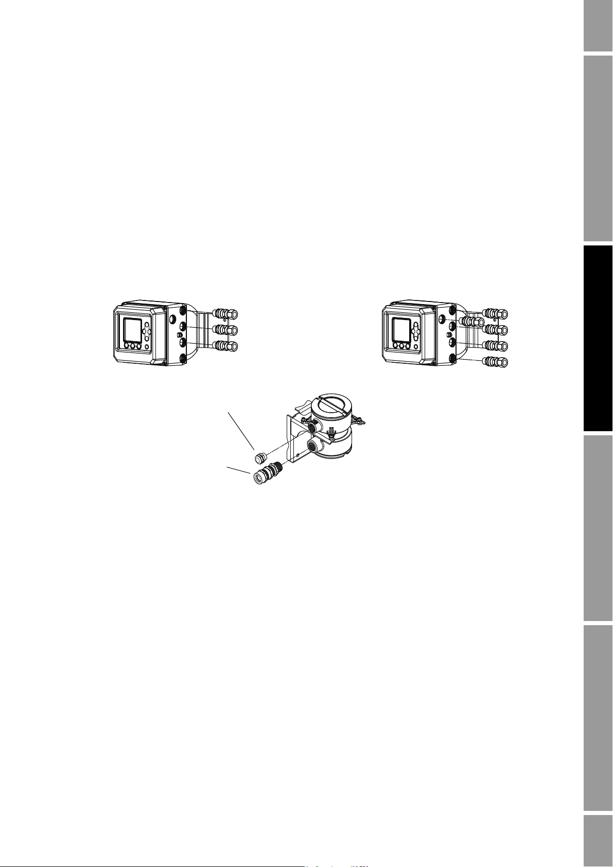
Cable gland
3/4˝–14 NPT
used with 9-wire conduit opening
Cable gland
1/2˝–14 NPT or M20 x1.5
used with 4-wire conduit opening
Transmitter model 3700*****B***** Transmitter model 3700*****C*****
Transmitter models
• 3500**F********
• 3500**G********
• 3700**F********
• 3700**G********
Remote core processor with remote transmitter installations also require 9-wire cable. Micro Motion
offers three types of 9-wire cable: jacketed, shielded, and armored. Refer to Micro Motion’s 9-Wire
Flowmeter Cable Preparation and Installation Manual for detailed descriptions of these cable types
and for assistance in selecting the appropriate cable for your installation.
2.10.2 Cable glands in remote core processor with remote transmitter installations
Depending on your transmitter model, several different cable glands may be shipped with the
transmitter and core processor. Refer to Figure 2-1 to identify the cable glands supplied by Micro
Motion. Be sure to use the appropriate cable gland for each component and location.
Figure 2-1 Cable glands supplied by Micro Motion
Installation Using the DisplayDigital Communications SetupBefore You Begin
2.11 I/O wiring
Note: This section applies to all Series 3000 devices.
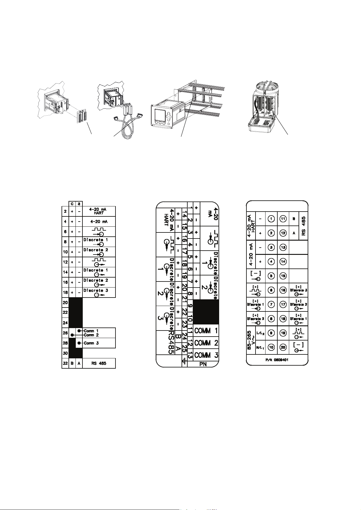
2.11.1 Terminals and terminal block locations
To locate the I/O terminal blocks on your Series 3000 platform, see Figure 2-2. To identify the I/O
terminals, see the appropriate terminal label in Figure 2-3.
Configuration and Use Manual 11
Page 24
Installation
Model 3300 or Model 3500
panel-mount
Input/output wiring terminals
Model 3300 or Model 3500
rack-mount
Input/output wiring terminals
Model 3350 or Model 3700
field-mount
Input/output wiring terminals
Label for Model 3300 or
Model 3500 with I/O cables
Card for Model 3300 or Model 3500 with
screw-type or solder-tail terminals
Label for Model 3350
or Model 3700
Note: The terminals labeled Comm 1, Comm 2, and Comm 3 are not for I/O wiring.
These terminals are for Micro Motion internal use only.
Figure 2-2 I/O terminal locations
Figure 2-3 I/O terminal labels
12 Micro Motion® Series 3000 MVD Transmitters and Controllers
Page 25
Installation
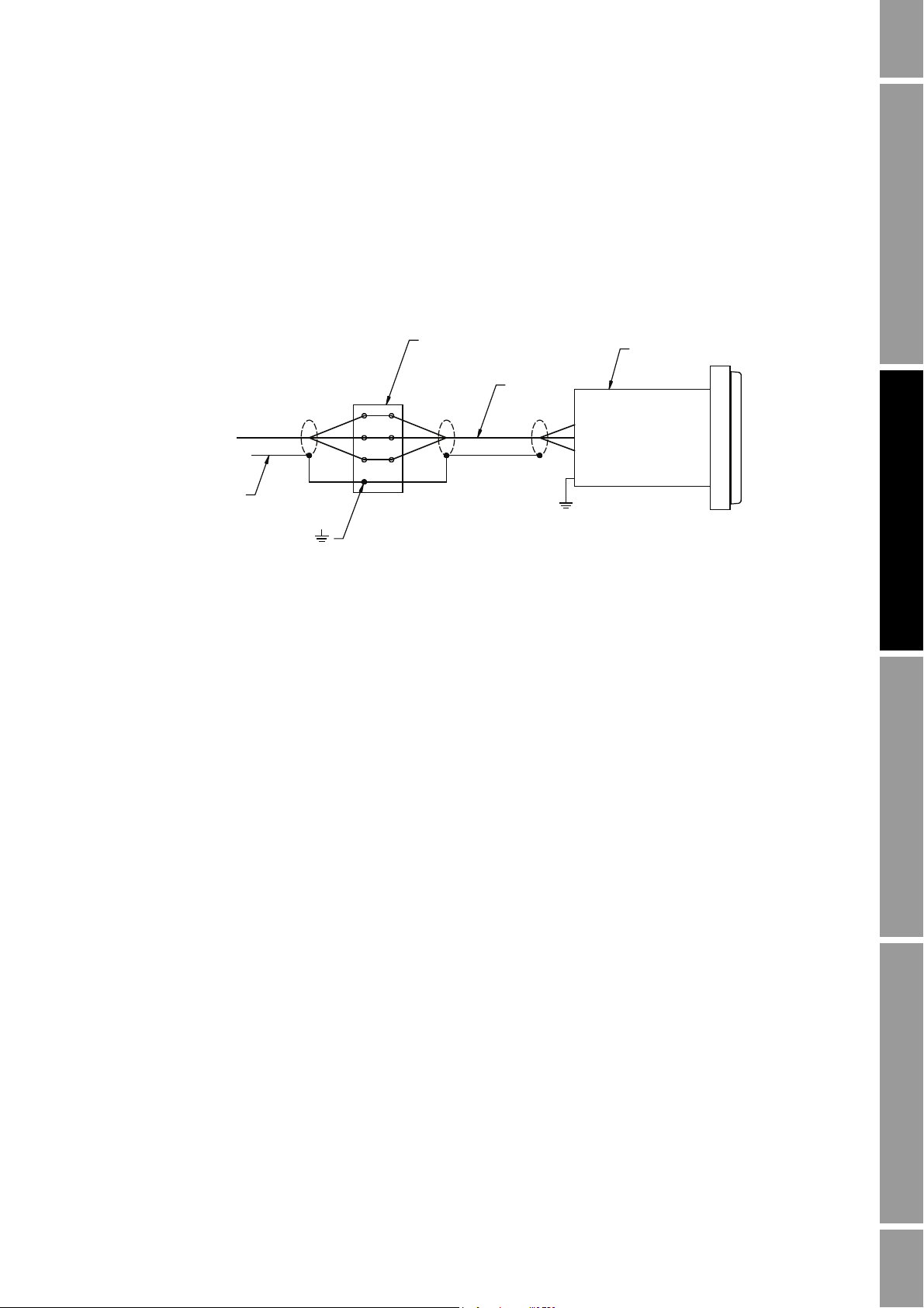
Cable shields
Te r m i n a l m ar ke d
Chassis
ground
Terminal block
I/O cable
Model 3300 or Model 3500
Ground shields at single
point only (at the remote
device, not at the
Series 3000 device)
2.11.2 Grounding
For all Series 3000 devices, the shields from the I/O wires should be grounded at a single point.
Ground the shields at the remote device, not at the Series 3000 device.
If you are installing a Model 3300 or Model 3500 panel-mount device with I/O cables, the terminal
block ground is available for continuation of user cable shielding to I/O cable shielding. The cable
connector does not connect the I/O cable shielding to the chassis ground. See Figure 2-4.
Figure 2-4 Shield wiring for I/O cable to field device
Installation Using the DisplayDigital Communications SetupBefore You Begin
2.11.3 Installing relays
If you will install a relay to connect the Series 3000 device’s discrete outputs to control devices, see
Appendix D for installation instructions.
Specifications for the Model 3100 relay (supplied by Micro Motion) are provided in Appendix C.
2.12 Digital communications wiring
If you will use digital communications between your Series 3000 device and a remote device (e.g., a
ticket printer, a PLC, a temperature or pressure sensor, or a PC running ProLink II), see Chapter 3 for
wiring instructions.
Configuration and Use Manual 13
Page 26

14 Micro Motion® Series 3000 MVD Transmitters and Controllers
Page 27

Chapter 3
Digital Communications Setup
3.1 About this chapter
This chapter explains how to install wiring for digital communications between the Series 3000
device and a remote device. The following are typical remote devices:
• Ticket printer
• Any PLC or control system
• PC running ProLink II
• 375 Field Communicator
• Temperature or pressure sensor
• HART Tri-Loop
Note: This chapter does not discuss configuration of digital communications. To configure digital
communications, see Chapter 13.
Installation Using the DisplayDigital Communications SetupBefore You Begin
3.2 Supported protocols
Table 3-1 describes the digital communications support provided on the Series 3000 device.
HART/Bell 202 is superimposed on the primary mA output, while all RS-485 protocols are
implemented on a dedicated terminal pair.
Table 3 -1 Series 3000 terminals, physical layers, and protocols
Terminals Physical layer Protocol
Primary mA output terminals Bell 202 HART
RS-485 terminals RS-485 Modbus
3.2.1 Obtaining the components
Identify and obtain the required components according to the physical layers and protocols you
will use.
3.2.2 RS-485 signal converter
RS-232 or USB conversion
If you need to convert the RS-485 signal to an RS-232 or USB signal, signal converters are available
from Micro Motion (part number PLKUSB485KIT or PLK485KIT). Contact Micro Motion for
information about ordering these converters.
HART
Printer
Configuration and Use Manual 15
Page 28

Digital Communications Setup
You may also order the IC521A-F signal converter with a ticket printer. Contact Micro Motion for the
appropriate ETO (engineered-to-order) number.
Depending on your remote device, you may also need a 9-pin to 25-pin adapter.
Note: The ProLink PC Interface Adaptor (PCIA) cannot be used with the Series 3000 device. Because
the PCIA does not control the ready-to-send (RTS) line, communication between the Series 3000
device and the remote device cannot be initiated.
Other conversion
If you need to convert the RS-485 signal to another signal, you must supply the appropriate signal
converter.
3.2.3 Bell 202 signal converter
RS-232 conversion
If you need to convert the Bell 202 signal to an RS-232 signal, as used by a PC’s serial port, signal
converters are available from Micro Motion (part number PLKUSB202KIT or PLK202KIT). Contact
Micro Motion for information about ordering these converters.
You may also need a Bell 202 cable or a 9-pin to 25-pin adapter.
Other conversion
If you need to convert the Bell 202 signal to another signal, you must supply the appropriate signal
converter or HART interface.
3.3 Setting up RS-485 communications
Follow the steps below to set up RS-485 communications between the Series 3000 device and a
remote device.
1. Locate and identify the RS-485 terminals on the Series 3000 device. Refer to Table 3-2 and
Figure 2-2. Additionally, the Series 3000 device has a label or card that shows input/output
wiring terminal designations. See Figure 2-3.
Note: The terminals labeled Comm 1, Comm 2, and Comm 3 are not for I/O wiring. These terminals
are for Micro Motion internal use only.
Table 3 -2 RS-485 wiring terminals
Model RS-485 terminals location/description
Model 3300 or Model 3500 with
screw-type or solder-tail connectors
Model 3300 or Model 3500 with
I/O cable
Model 3350 or Model 3700 Gray terminal block, non-intrinsically safe wiring
Input/output wiring terminal block a 32 c 32
I/O terminal block on DIN rail 25 24
compartment
RS-485 terminals
AB
12 11
16 Micro Motion® Series 3000 MVD Transmitters and Controllers
Page 29
Digital Communications Setup
RS-485 to RS-232
signal converter
RS-485 A
RS-485 B
Wire size is 24 AWG (0,25 mm2)
For long-distance communication, or if noise from an
external source interferes with the signal, install a 120 Ω,
½ watt resistor at each end of the wiring loop between the
Series 3000 device and the signal converter
Remote
device
Serial port connection
(with 9-pin to 25-pin
adapter if necessary)
Input/output terminal block
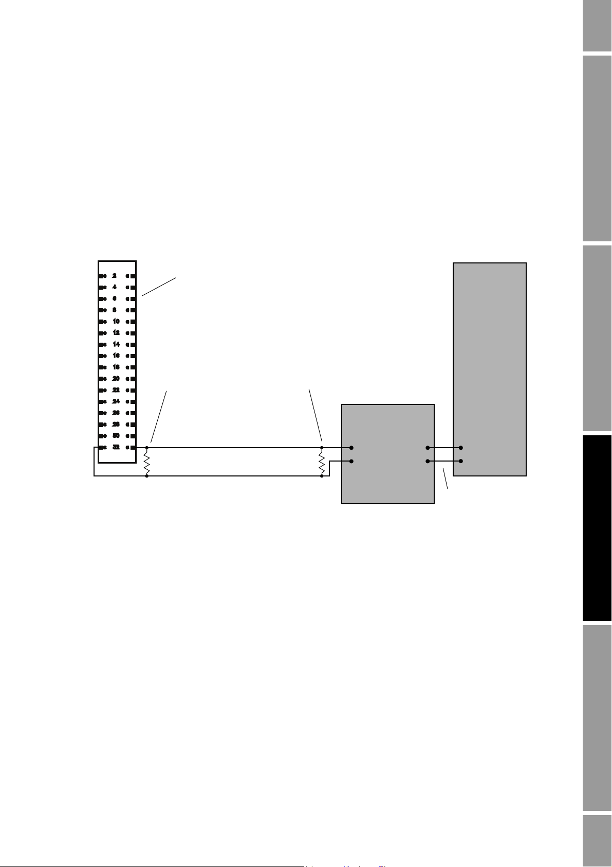
2. Using twisted-pair shielded cable, and a signal converter if required, connect the remote device
to the RS-485 output terminals on the Series 3000 device. Maximum cable length between the
Series 3000 and remote device is 4000 feet (1200 meters).
• Model 3300 or Model 3500 with screw-type or solder-tail terminals: see Figure 3-1
• Model 3300 or Model 3500 with I/O cables: see Figure 3-2
• Model 3350 or Model 3700: see Figure 3-3
3. Add resistance if required.
4. Configure RS-485 communications as described in Section 13.3.
Figure 3-1 Model 3300 or Model 3500 with RS-485 signal converter – Screw-type or solder-tail connectors
Installation Using the DisplayDigital Communications SetupBefore You Begin
Configuration and Use Manual 17
Page 30
Digital Communications Setup
RS-485 to RS-232
signal converter
Remote
device
RS-485 A
RS-485 B
For long-distance communication, or if noise
from an external source interferes with the
signal, install a 120 Ω, ½ watt resistor at each
end of the wiring loop between the
Series 3000 device and the signal converter
Wire size is 24 AWG (0,25 mm2)
Serial port connection
(with 9-pin to 25-pin
adapter if necessary)
Input/output terminal block
RS-485 B
RS-485 A
Wire size is 22 AWG (0,35 mm2)
For long-distance communication, or if noise from an
external source interferes with the signal, install a 120 Ω,
½ watt resistor at each end of the wiring loop between the
Series 3000 device and the signal converter
RS-485 to RS-232
signal converter
Remote
device
Serial port connection
(with 9-pin to 25-pin
adapter if necessary)
Input/output terminal block
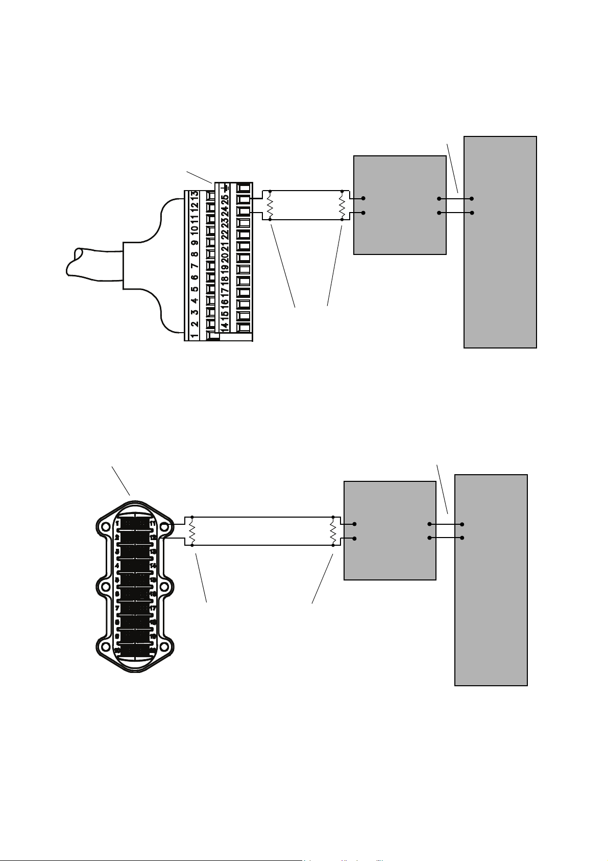
Figure 3-2 Model 3300 or Model 3500 with RS-485 signal converter – I/O cables
Figure 3-3 Model 3350 or Model 3700 with RS-485 signal converter
18 Micro Motion® Series 3000 MVD Transmitters and Controllers
Page 31

Digital Communications Setup
3.4 Setting up Bell 202 communications
Follow the steps below to set up Bell 202 communications between the Series 3000 device and a
remote device.
1. Locate and identify the primary mA output terminals on the Series 3000 device. Refer to
Table 3-3 and Figure 2-2. Additionally, the Series 3000 device has a label or card that shows
input/output wiring terminal designations. See Figure 2-3.
Table 3 -3 Bell 202 wiring terminals
Primary mA output terminals
Model
Model 3300 or Model 3500 with
screw-type or solder-tail
connectors
Model 3300 or Model 3500 with
I/O cable
Model 3350 or Model 3700 Gray terminal block, non-intrinsically safe
location/description
Input/output wiring terminal block c 2 a 2
I/O terminal block on DIN rail 14 15
wiring compartment
2. Determine if the primary mA output will be used to report both analog (mA) process data and
HART digital data. It may already be wired for analog output.
3. Using twisted-pair shielded cable, and a signal converter if required, connect the remote device
to the Series 3000 device’s primary mA output terminals. Maximum cable length between the
Series 3000 device and the remote device is 4000 feet (1200 meters).
If the output will be used for HART digital communications only, see the following:
• Model 3300 or Model 3500 with screw-type or solder-tail terminals: Figure 3-4
• Model 3300 or Model 3500 with I/O cables: Figure 3-5
• Model 3350 or Model 3700: Figure 3-6
Additionally, the following wiring examples are provided:
Primary mA terminals
+–
Installation Using the DisplayDigital Communications SetupBefore You Begin
21
• Using the primary mA outputs for both digital communication and analog output
(HART/analog single-loop wiring) – see Figure 3-7
• Wiring the Series 3000 device to a HART multidrop network – see Figure 3-8
• Wiring for pressure or external temperature compensation – see Figure 3-9
• Wiring the Series 3000 device to a HART Tri-Loop – see Figure 3-10
• Wiring for pressure or external temperature compensation with HART Tri-Loop – see
Figure 3-11
Note: The HART loop is not polarity-sensitive.
4. The HART interface must be connected across a resistance of 250–600 Ω. Add resistance to
the connection if necessary.
5. Configure Bell 202 communications as described in Section 13.4.
Configuration and Use Manual 19
Page 32

Digital Communications Setup
HART interface
Wire size is 24 AWG (0,25 mm2)
Remote
device
Serial port connection
(with 9-pin to 25-pin
adapter if necessary)
600 Ω maximum loop resistance
250 Ω minimum loop resistance
Input/output terminal block
HART interface
Remote
device
Wire size is 24 AWG (0,25 mm2)
Serial port connection
(with 9-pin to 25-pin
adapter if necessary)
Input/output terminal block
600 Ω maximum loop resistance
250 Ω minimum loop resistance
Figure 3-4 Model 3300 or Model 3500 with HART interface – Screw-type or solder-tail connectors
Figure 3-5 Model 3300 or Model 3500 with HART interface – I/O cables
20 Micro Motion® Series 3000 MVD Transmitters and Controllers
Page 33

Digital Communications Setup
HART interface
Remote
device
Serial port connection
(with 9-pin to 25-pin
adapter if necessary)
Wire size is 22 AWG (0,35 mm2)
Input/output terminal block
600 Ω maximum loop resistance
250 Ω minimum loop resistance
Resistance:
• Analog only: 820 Ω maximum loop resistance
• HART only or HART/analog:
- 600 Ω maximum loop resistance
- 250 Ω minimum loop resistance
+–
+
–
+
–
Terminal block for Model 3300 or
Model 3500 with screw-type or
solder-tail connectors
Terminal block for Model 3300
or Model 3500 with IO cables
Terminal block for
Model 3350 or Model 3700
HART device
(with optional signal
converter)
HART device
(with optional
signal converter)
HART device
(with optional signal
converter)
Figure 3-6 Model 3350 or Model 3700 with HART interface
Installation Using the DisplayDigital Communications SetupBefore You Begin
Figure 3-7 HART/analog single-loop wiring
Configuration and Use Manual 21
Page 34

Digital Communications Setup
ProLink II v2.x,
HART Communicator, or AMS
software
(with HART interface)
600 Ω maximum loop resistance
250 Ω minimum loop resistance
HART-compatible
transmitters
SMART FAMILY
™
transmitters
Note: For optimum HART communication, make
sure the output loop is single-point-grounded to
an instrument-grade ground.
24 VDC loop power
supply required for
HART 4–20 mA
passive transmitters
Series 3000
DC power
supply
Series 3000
device
Primary mA output terminals
Pressure or
temperature
device
+
–
+–
600 Ω maximum loop resistance
250 Ω minimum loop resistance
Resistance as required for your device
Figure 3-8 HART multidrop wiring with SMART FAMILY™ transmitters and a configuration tool
Figure 3-9 Wiring for pressure or external temperature compensation
22 Micro Motion® Series 3000 MVD Transmitters and Controllers
Page 35

Digital Communications Setup
DC power
supply
Series 3000
device
Primary mA output terminals
+
–
600 Ω maximum loop resistance
250 Ω minimum loop resistance
Channel 2
Channel 3
Channel 1
Burst input
HART
Tri-Loop
DC power
supply
Series 3000
device
Primary mA
output terminals
+
–
600 Ω maximum loop resistance
250 Ω minimum loop resistance
Channel 1
Burst input
HART
Tri-Loop
DC power
supply
Pressure or
temperature
device
+
–
+–
Channel 2
Channel 3
Resistance as required for your device
Figure 3-10 Wiring for HART Tri-Loop
Installation Using the DisplayDigital Communications SetupBefore You Begin
Figure 3-11 Wiring for pressure or external temperature compensation with HART Tri-Loop
Configuration and Use Manual 23
Page 36

24 Micro Motion® Series 3000 MVD Transmitters and Controllers
Page 37

Chapter 4
5← DEVICE 1 →2
Mass Flow Rate
2.33
g/s
Mass Total
485.88
g
RESET EXIT
Security
button
Alarm bar
VIEW or EXIT
button
Using the Display and Menu System
4.1 About this chapter
This chapter explains how to use the Series 3000 display and menu system. Using the display, you can
move through the menus, configure the application, monitor and control the application, and perform
maintenance and diagnostic tasks.
4.2 Startup display
When the Series 3000 device is powered on, it automatically tests its display. During display testing,
the screen darkens for approximately five seconds. After the display test is completed:
1. The Micro Motion logo is displayed for two to three seconds.
2. An application list is displayed for two to three seconds.
3. The device enters operation mode:
• If the discrete batch application is not installed, the process monitor screen is displayed, as
shown in Figure 4-1.
• If the discrete batch application is installed, the batch process screen is displayed (see
Figure 18-1).
Figure 4-1 Process Monitor screen
Installation Using the DisplayDigital Communications SetupBefore You Begin
4. If there are any active alarms, the alarm category will be displayed in the alarm bar. To view,
acknowledge, or respond to the alarms, see Chapter 22.
Configuration and Use Manual 25
Page 38

Using the Display and Menu System
Management
System
Inputs
Discrete batch
(1)
Measurements
Outputs
Monitoring
Digital communication
Maintenance Security Language
Security
Passwords
Weights & Measures
(3)
Language
Configuration
Active alarm log
Alarm history
Alarm event log
Batch inventory
(1)
Process inventory
Meter fingerprinting
(2)
Audit trail
(3)
Calibration
Diagnostics
Meter verification
(4)
(1) Displayed only if discrete batch application is installed.
(2) Available only on systems with the standard core processor.
(3) Displayed only if custody transfer application is installed.
(4) Available only on systems with the enhanced core processor,
and only if the meter verification option was purchased.
View
Preset
selections
(1)
Process
totalizers
Density
curves
(2)
Active alarm
log
Applications
list
Process
monitoring
Batch
inventory
(1)
Diagnostic
monitor
LCD
options
(1) Displayed only if discrete batch application is installed.
(2) Displayed only if enhanced density application is installed.
4.3 Menu systems
Most Series 3000 display functions are organized into two menu systems:
• The Management menu allows you to perform configuration and maintenance tasks.
• The View menu allows you to monitor and control the process.
Figures 4-2 and 4-3 show high-level views of these menu systems. For complete menu flowcharts, see
Appendix F.
Figure 4-2 Management menu
Figure 4-3 View menu
26 Micro Motion® Series 3000 MVD Transmitters and Controllers
Page 39

Using the Display and Menu System
5← DEVICE 1 →2
Mass Flow Rate
2.33
g/s
Mass Total
485.88
g
PRINT RESET EXIT
DEVICE 1
Configuration
Maintenance
Security
Language
SEL EXIT
To enter the menus:
• To enter the Management menu system, press the
the lower right corner of the display, marked with a padlock icon (see Figure 4-1). You may or
may not be required to enter a password (see the following section).
Security button. The Security button is in
• To enter the View menu system, press the
VIEW or EXIT button (see Figure 4-1).
4.3.1 Accessing management functions
You can use the
menus. When the
Security button to access management functions from any point in the Series 3000
Security button is pressed:
• If security is disabled, the Management menu will be displayed immediately. See Figure 4-4.
By default, security is disabled.
• If security has been enabled, you will be prompted to enter a password. See Figure 4-5. There
are two passwords:
- The configuration password enables access to all functions. When it is entered, the
Management menu is displayed.
- The maintenance password enables access to the maintenance functions. When it is
entered, the Maintenance menu is displayed.
Both passwords consist of a sequence of four cursor control button presses. To enter a password:
1. Press the four cursor control buttons in the correct sequence.
2. Press
SEL.
To configure and enable security, see Chapter 5.
Figure 4-4 Pressing Security button from Process Monitor screen – Security disabled
Installation Using the DisplayDigital Communications SetupBefore You Begin Installation Using the DisplayDigital Communications SetupBefore You Begin Installation Using the DisplayDigital Communications SetupBefore You Begin Installation Using the DisplayDigital Communications SetupBefore You Begin
Configuration and Use Manual 27
Page 40

Using the Display and Menu System
Enter Password
SEL HELP EXIT
5← DEVICE 1 →2
Mass Flow Rate
2.33
g/s
Mass Total
485.88
g
PRINT RESET EXIT
Figure 4-5 Pressing Security button from Process Monitor screen – Security enabled
4.3.2 Shortcuts
From any point in the menu system, you can:
• Return to the Management menu (if security is disabled) or the password entry screen (if
security is enabled) by pressing the
• Return to the operating screen by pressing the
Security button, as described in the previous section.
Security button, then pressing the EXIT button.
4.4 Using the function buttons
The buttons at the bottom of the display are the function buttons. The functions performed by the
buttons vary, depending on the screen and the current state of the application. The function currently
assigned to the button is always displayed on the screen, above the button. The buttons are sometimes
referred to as F1, F2, and F3. See Figure 4-6.
Note: The left and right cursor control buttons may also be used as function buttons. See Figure 4-6.
If a cursor is shown on the display, the action performed by the function button applies to the item
where the cursor is located. Before pressing a function button, be sure the cursor is located correctly.
See Section 4.5.
28 Micro Motion® Series 3000 MVD Transmitters and Controllers
Page 41

Using the Display and Menu System
ALARMS
DEVICE 1
Configuration
Maintenance
Security
Language
SEL HELP EXIT
F3 function button
VIEW Access the View menu
EXIT Exit to previous menu or cancel a change
NO Cancel action
PREV Return to the previous screen
ABORT • Abort sensor zero
• Abort calibration
F2 function button
HELP Show a help screen
RESUME Resume a batch that has been stopped
RESET Reset total
PRINT Print a ticket
NEXT Advance to the next screen
ACKALL Acknowledge all alarms
RESET-T Complete the current custody transfer transaction
F1 function button
START Start batch or totalizers
STOP • Stop totalizers
• Stop batch before target is achieved (batch can be resumed)
END End batch before target is achieved (batch cannot be resumed)
RESET Reset total
SEL Select the highlighted menu item
CHG Make a change to the highlighted menu item
SAVE Save a change
YES Proceed with action
ACK Acknowledge an alarm message
PRINT Print a ticket
CLEAR Reset the rollover indicator (R) for the transfer inventory
F3 function button
F1 function button
Figure 4-6 Function buttons
Installation Using the DisplayDigital Communications SetupBefore You Begin Installation Using the DisplayDigital Communications SetupBefore You Begin Installation Using the DisplayDigital Communications SetupBefore You Begin Installation Using the DisplayDigital Communications SetupBefore You Begin
Configuration and Use Manual 29
Page 42

Using the Display and Menu System
4.5 Using the cursor control buttons
The cursor control buttons move the cursor around the display menus. In menus, the cursor is a
reverse-video highlight bar.
•Use the
Up and Down buttons to locate the cursor at the menu item you want to select or
change.
• After locating the cursor at the desired menu item, press
select or change the item.
4.5.1 Selecting from a list
For enumerated lists, pressing
CHG will display a separate screen from which you can choose the
desired option. From that screen:
• Press
• Press
SAVE to save the change and return to the previous screen, or
EXIT or the Left button to return to the previous screen without saving.
4.5.2 Changing a variable value
If you need to change the value of a variable, the cursor appears as a line under a character in the
current value.
• If the variable has a value of Yes or No, all cursor control buttons toggle between the two
choices.
• If the variable has a numeric or character value, press the
to increase or decrease the value of the character at the cursor.
• If the variable has more than one digit or character, press the
buttons to move the cursor to the next or previous character.
When the value is correct, press
SEL or CHG, or the Right button, to
Up and Down cursor control buttons
Left and Right cursor control
SAVE.
Press
EXIT to return to the previous screen without saving.
4.5.3 Cursor control example
Figure 4-7 shows a typical configuration sequence involving both a menu item and a variable.
Pressing
HELP produces a screen that has help for the item at the cursor.
4.5.4 Process monitor
In the process monitor, use the
next or previous screen. There are five screens.
• Press the
• Press the
• To assign variables to each process monitor screen, see Chapter 12.
4.6 Scientific notation
Scientific notation is used on some screens for displaying values that contain more digits than the
display can show, or that exceed the precision of the floating point data type. For example, the value
1234000.000 would be displayed as 1.234E6 or 1.234+6.
Left and Right cursor control buttons to scroll from one screen to the
Right button to scroll to the next screen.
Left button to scroll to the previous screen.
30 Micro Motion® Series 3000 MVD Transmitters and Controllers
Page 43

Using the Display and Menu System
5← DEVICE 1 →2
Mass Flow Rate
2.33
g/s
Mass Total
485.88
g
PRINT RESET EXIT
Density
↓
Density Units
g/cm3
Density Damping
1.7 sec
Density Cutoff
0.005
000 g/cm3
Slug Low Limit
0.005000 g/cm3
SAVE HELP EXIT
Density
↓
Density Units
g/cm3
Density Damping
1.7 sec
Density Cutoff
0.005000 g/cm3
Slug Low Limit
0.005000 g/cm3
CHG HELP EXIT
Move cursor up/Scroll up
Move cursor down/Scroll down
EXIT
Current
selection is
highlighted
Increase value at cursor
or toggle YES/NO
Decrease value at
cursor or toggle YES/NO
Var iabl e
Indicates items
available to scroll
Current
selection is
underscored
Menu item
Move cursor to left
Move cursor to right
SELECT
Process monitor
Scroll to previous screen
Scroll to next screen
Figure 4-7 Cursor control buttons
Installation Using the DisplayDigital Communications SetupBefore You Begin Installation Using the DisplayDigital Communications SetupBefore You Begin Installation Using the DisplayDigital Communications SetupBefore You Begin Installation Using the DisplayDigital Communications SetupBefore You Begin
Configuration and Use Manual 31
Page 44

32 Micro Motion® Series 3000 MVD Transmitters and Controllers
Page 45

Chapter 5
CAUTION
Security
Maintenance
• Press 1
• Press 2
• Press 3
• Press 4
Security Passwords Weights & Measures
(2)
(see Chapter 14)
Configuration
• Press 1
• Press 2
• Press 3
• Press 4
Enable security
Write protect
(1)
Totalizer reset
(1)
(1) Displayed only if the custody transfer application is not installed.
(2) Displayed only if the custody transfer application is installed.
(3) Displayed only if World Area is set to OIML.
Alarm log
(2)(3)
(see Chapter 14)
Configuring Security and Language
5.1 About this chapter
This chapter explains how to configure security and select the language for the Series 3000 display.
Security and language parameters are listed in Figures 5-1 and 5-2
Failure to perform configuration tasks in the proper sequence could result in an incomplete
configuration. See Section 1.7 for the recommended configuration sequence.
Changing configuration can affect device operation.
Set control devices for manual operation before changing device configuration.
.
Configuring System Data Configuring APIConfiguring InputsConfiguring Security & Language
5.2 Security menu
Use the Security menu, shown in Figure 5-1, to access and configure security and passwords. The
Security menu is accessed through the Management menu, as described in Chapter 4.
To configure security for weights and measures (custody transfer) applications, see Chapter 14.
Figure 5-1 Security menu
Configuration and Use Manual 33
Page 46

Configuring Security and Language
5.3 Security
Security can be used for the following three functions:
• To control access to the Management menu
• To write-protect the Series 3000 device configuration
• To control how process totalizers and inventories can be reset
Note: If custody transfer is implemented, the write-protection and totalizer reset control functions are
handled by the custody transfer application, and are not available here. See Chapter 14.
Note: If custody transfer (OIML) is implemented, you can also define an alarm log password to
control access to the active alarm log, the alarm event log, and alarm history. See Chapter 14.
5.3.1 Management menu access
Access to the Management menu can be controlled by two passwords:
• The configuration password enables access to all Management menus
• The maintenance password enables access to the Maintenance portion of the Management
menu system
When the Security button is pressed (see Section 4.3.1):
• If security is enabled, you will be prompted to enter a password. Depending on the password
you enter, either the Management menu or the Maintenance menu is displayed.
• If security is disabled, the Management menu is displayed immediately.
The configured passwords are stored even if security is disabled, so you can re-enable them at any
time.
It is not possible to activate only the configuration password or only the maintenance password.
To enable security for the Management menu, set
To disable security for the Management menu, set
Enable Security to Enable.
Enable Security to Disable.
The passwords are a combination of four button presses, using any of the four cursor control buttons:
Up, Down, Left, and Right.
To set a password:
1. Use the menu to select the password you are defining.
2. For
Press 1 through Press 4, specify which cursor control button must be pressed.
To enter a password:
1. Press the four cursor control buttons in the correct sequence.
2. Press
SEL.
5.3.2 Write-protecting the device configuration
When the device is in write-protect mode, the configuration data stored in the device and core
processor cannot be changed until write-protect mode is disabled.
To enable write-protection, set
To disable write-protection, set
Write Protect to Enable.
Write Protect to Disable.
Note: If write-protection is enabled, process totalizers cannot be reset unless the flow rate is zero.
34 Micro Motion® Series 3000 MVD Transmitters and Controllers
Page 47

Configuring Security and Language
Language
Language
Language list
5.3.3 Controlling process totalizer and process inventory reset
This feature allows you to specify the methods that can be used to reset process totalizers and process
inventories:
No Reset – Cannot be reset using either the display or remote communications (e.g.,
•
ProLink II or a HART or Modbus tool).
•
Display Only – Can be reset only via the display on the Series 3000 device.
•
Remote Only – Can be reset only via remote communications (e.g., ProLink II or a HART or
Modbus tool).
•
Display & Remote – Can be reset using any communications method.
For definitions of process totalizers, process inventories, and other totalizer types, and additional
information on managing totalizers and inventories, see Chapter 20.
5.4 Language menu
Use the Language menu, shown in Figure 5-2, to access and configure language parameters. The
Language menu is accessed through the Management menu, as described in Chapter 4.
The configured language will be used for all Series 3000 screens. The display changes immediately.
Configuring System Data Configuring APIConfiguring InputsConfiguring Security & Language
Figure 5-2 Language menu
Your choice of language affects the notation used for various units. If English is selected, English
notation is used. If French or German is selected, European notation is used.
Configuration and Use Manual 35
Page 48

36 Micro Motion® Series 3000 MVD Transmitters and Controllers
Page 49

Chapter 6
CAUTION
System
Hour
Minute
Second
Tag Time Date Alarm severity
Day
Month
Ye a r
Electronics alarms
Process alarms
Sensor alarms
(1)
Configuration alarms
(1) Displayed only if you are configuring a Model 3500 or Model 3700 transmitter.
Configuring System Data
6.1 About this chapter
This chapter explains how to configure system data. System parameters are listed in Figure 6-1.
Failure to perform configuration tasks in the proper sequence could result in an incomplete
configuration. See Section 1.7 for the recommended configuration sequence.
Changing configuration can affect device operation.
Set control devices for manual operation before changing device configuration.
6.2 System menu
Use the System menu, shown in Figure 6-1, to access and configure system parameters. The System
menu is accessed through the Configuration option of the Management menu. To access the
Management menu, see Chapter 4.
Configuring System Data Configuring APIConfiguring InputsConfiguring Security & Language
Figure 6-1 System menu
Configuration and Use Manual 37
Page 50

Configuring System Data
6.3 System parameters
System parameters are defined in Table 6-1.
Table 6 -1 System parameters
Variable Default Description
(1)
Ta g
Time Current time Enter 2 digits for hours, 2 digits for minutes, and 2 digits for seconds
Date Current date Enter 4 digits for the year, a character code for the month, and 2 digits for the
Alarm severity Select alarm to be reclassified. See Section 6.3.1, below.
(1) This tag is also known as the HART tag or the software tag. It is not the HART polling address (also called the HART slave address).
To configure the HART polling address, see Section 13.4.
Device 1 • Enter up to 8 digits and/or characters that uniquely identify this platform
• The tag will appear on operation screens
day
6.3.1 Alarm severity
Alarms are organized into four categories. Within each category, alarms are classified into three levels
of severity. The severity level controls device behavior when the alarm condition occurs. See
Tabl e 6 -2 .
Table 6 -2 Alarm severity levels
Severity level Device action
Fault If this condition occurs, an alarm will be generated and all outputs go to their configured
Informational If this condition occurs, an alarm will be generated but output levels are not affected.
Ignore If this condition occurs, no alarm will be generated (no entry is added to the active alarm
fault levels. See Chapter 8.
log).
Some alarms can be reclassified. For example:
• The default severity level for Alarm A020 (cal. factors missing) is Fault, but you can
reconfigure it to either Informational or Ignore.
• The default severity level for Alarm A102 (drive over-range) is Informational, but you can
reconfigure it to either Ignore or Fault.
If an alarm can be reclassified, the
CHG function is assigned to the F1 button. If an alarm cannot be
reclassified, the F1 button is unassigned. The alarm listings in Section 22.7 also provide information
on which alarms can be reclassified.
38 Micro Motion® Series 3000 MVD Transmitters and Controllers
Page 51

Chapter 7
CAUTION
Configuring Inputs
7.1 About this chapter
This chapter explains how to configure inputs. Inputs include all the software parameters listed in
Figures 7-1 and 7-2.
Failure to perform configuration tasks in the proper sequence could result in an incomplete
configuration. See Section 1.7 for the recommended configuration sequence.
Changing configuration can affect device operation.
Set control devices for manual operation before changing device configuration.
Configuring System Data Configuring APIConfiguring InputsConfiguring Security & Language
7.2 Inputs menu
Use the Inputs menu, shown in Figures 7-1 and 7-2, to access and configure input parameters. The
Inputs menu is accessed through the Configuration option of the Management menu. To access the
Management menu, see Chapter 4.
You will be:
• Configuring core processor parameters:
- Enabling or disabling core processor inputs
- Configuring process variables
- Configuring sensor calibration data
- Configuring sensor information
- Assigning discrete inputs to actions
• Configuring the frequency input
• Configuring the discrete inputs
• Configuring external inputs
• Configuring LD Optimization
Note: If you are configuring a Model 3300 or Model 3350 controller, the core processor parameters
and external inputs parameters are not displayed. To assign a discrete input to an action on these
platforms, use the frequency input menu shown in Figure 7-2.
Configuration and Use Manual 39
Page 52

Configuring Inputs
Inputs
Flow variables
•Flow damping
• Flow direction
• Mass units
• Mass low flow cutoff
• Volume flow type
• Volume units
(2)
• Std gas volume units
(3)
•Std gas volume
cutoff
(3)(4)
• Std gas density
(3)
• Vol low flow cutoff
(2)
• Special mass units
• Special volume units
(2)
• Special gas std units
(3)
Enable/
Disable
Configure
process var
Sensor cal data
T-Series Setup
Core processor
(1)
Other inputs
See Figure 7-2
Ye s
•FCF
•FTG
•FFQ
•D1
•D2
•D3
•D4
•K1
•K2
•K3
•K4
•FD
•DT
•DTG
•DFQ1
•DFQ2
• Temp. slope
• Temp. offset
• Mass factor
• Density factor
• Volume factor
Density
• Density units
• Density damping
• Density cutoff
• Slug low limit
• Slug high limit
• Slug duration
No
•Flow cal
•D1
•D2
•K1
•K2
•FD
• Dens temp coeff
• Temp. cal factor
• Mass factor
• Density factor
• Volume factor
•Start zero
• Reset mass total
• Reset volume total
• Reset API cor vol tot
(5)
• Reset ED std vol tot
(6)
• Reset ED net mass to
(6)
• Reset ED net vol tot
(6)
• Reset all totals
• Start/stop all totals
• Start meter verify
(7)
Sensor
information
• Sensor model no.
• Sensor serial no.
• Sensor material
• Sensor flange
• Sensor liner
(1) Displayed only if you are configuring a Model 3500 or Model 3700 transmitter.
(2) Displayed only if Volume Flow Type = Liquid Volume.
(3) Displayed only if Volume Flow Type = Gas Standard Volume.
(4) Displayed only on systems with the enhanced core processor.
(5) Displayed only if petroleum measurement application is installed.
(6) Displayed only if enhanced density application is installed.
(7) Displayed only if Smart Meter Verification is installed.
Discrete inputs
Temperature
• Temperature units
• Temperature damping
LD Optimization
Figure 7-1 Inputs menu – Core processor parameters
40 Micro Motion® Series 3000 MVD Transmitters and Controllers
Page 53

Configuring Inputs
Inputs
Core processor inputs
See Figure 7-1
Frequency input
Flow rate units Scaling method
Frequency=flow
• Frequency
•Flow
•K-factor
Pulses/unit
• Pulses/unit
•K-factor
Units/pulse
•Units/pulse
•K-factor
Discrete inputs External inputs
(2)
• Polling control
• Polling variable
• External tag
• Pressure compensation
(3)
• Pressure units
(3)
•Flow factor
(3)
• Density factor
(3)
• Cal pressure
(3)
• External temperature
compensation
(4)
2Polling variable 1
Polar ity
2Discrete input 1
(1) Displayed only if you are configuring a Model 3300 or Model 3350 controller.
(2) Displayed only if you are configuring a Model 3500 or Model 3700 transmitter.
(3) Displayed only if Polling Variable is set to Pressure.
(4) Displayed only if Polling Variable is set to Temperature.
Reset all totals
(1)
Start/Stop all totals
(1)
None
Discrete input 1
Discrete input 2
Figure 7-2 Inputs menu – Frequency input, discrete input, external inputs
Configuring System Data Configuring APIConfiguring InputsConfiguring Security & Language
7.3 Configuring the core processor parameters
Core processor parameters include:
• Core processor inputs
• Process variables
• Sensor calibration data
• Sensor information
Configuration and Use Manual 41
Page 54

Configuring Inputs
7.3.1 Enabling and disabling core processor inputs
Core processor inputs are enabled by default. By disabling the core processor, you disable all core
processor input signals and alarms. Disabling them might be desirable while you are connecting the
sensor, or if you are using only the frequency input to measure flow.
Table 7-1 describes the core processor input options.
Table 7 -1 Enabling or disabling inputs and alarms
Variable Default Description
Enable core processor Yes If set to No:
• The platform will not use input signals from the sensor to measure flow,
density, or temperature.
• The platform will not produce the following alarms: warming up, cal in
progress, drive overrange, temperature overrange, temperature failure,
sensor failure, transmitter failure, density overrange, density failure, mass
flow overrange, volume overrange, calibration failure, calibration complete,
calibration aborted, RTD failure, charize required, slug flow, slug timeout
(1) For more information about alarms, see Chapter 22.
7.3.2 Configuring process variables
Process variables include mass flow, volume flow, density, and temperature. For each process
variable, several parameters can be configured.
(1)
.
Mass flow and volume flow parameters
Mass flow and volume flow parameters are listed and defined in Table 7-2. Note that you can
configure the transmitter to measure either liquid volume flow or gas standard volume flow,
depending on the setting of Volume Flow Type.
Details about the Flow Direction parameter are provided in Table 7-3. Units for mass flow and
volume flow parameters are listed in Tables 7-4 through 7-6. Special units for mass and volume are
defined and described in the section entitled Special units later in this chapter.
Table 7 -2 Flow parameters
Variable Default Description
Flow damping 0.8 sec • Damping filters out noise or the effects of rapid changes in the flow rate
without affecting measurement accuracy. See the section entitled Damping
later in this chapter. For gas applications, Micro Motion recommends a
minimum flow damping value of 2.56 seconds. Range is 0.0–51.2 seconds.
• Milliamp outputs have an additional damping parameter. See Section 8.4.4.
Flow direction Forward • Controls how flow through the sensor will affect outputs and totalizers.
Mass units g/s • Select the desired unit of mass flow. See Table 7-4.
Mass low flow cutoff 0.00000 g/s • Enter the mass flow rate below which mass flow outputs and displays will
• For the effect of flow direction on milliamp outputs, see Figure 7-3 if the 4 mA
value of the milliamp output is set to 0, and see Figure 7-4 if the 4 mA value
of the milliamp output is set to a negative value. For a discussion of these
figures, see the examples following the figures. For information on setting the
4 mA value, see Section 8.4.4.
• For the effect of flow direction on frequency outputs, totalizers, and flow
values reported via digital communication, see Table 7-3.
• Mass flow outputs and displays will indicate mass flow in the selected unit.
The mass totalizer and inventory will use the corresponding mass unit.
indicate zero flow. See the section entitled Cutoffs later in this chapter.
• Milliamp outputs have an additional cutoff parameter. See Section 8.4.4.
42 Micro Motion® Series 3000 MVD Transmitters and Controllers
Page 55

Configuring Inputs
Reverse
flow
(1)
20
12
4
x0
20
12
4
-x x0
Milliamp output configuration:
• 20 mA value = x
• 4 mA value = 0
To set the 4 mA and 20 mA values, see
Section 8.4.4.
Forward
flow
(2)
Zero flow
Reverse
flow
(1)
Forward
flow
(2)
Zero flow
Flow direction parameter:
• Forward only
Flow direction parameter:
• Reverse only
• Negate/Forward only
20
12
4
-x x0
Reverse
flow
(1)
Forward
flow
(2)
Zero flow
Flow direction parameter:
• Absolute value
• Bidirectional
• Negate/Bidirectional
(1) Process fluid flowing in opposite direction from flow direction arrow on sensor.
(2) Process fluid flowing in same direction as flow direction arrow on sensor.
-x
mA output
mA output
mA output
Table 7 -2 Flow parameters continued
Variable Default Description
Volume flow type Liquid • Select the desired volume flow type.
(1)
(3)(2)
(1)
l/s • Select the desired unit of liquid volume flow. See Table 7-5. The liquid
0.00000 l/s • Enter the liquid volume flow rate below which volume flow outputs and
SCFM • Select the desired unit of gas standard volume flow. See Table 7-6. The gas
0.0000 SCFM • Enter the volume flow rate below which volume flow outputs and displays will
(2)
0.10000 g/cm3• Enter the standard density of the gas you are measuring. See the section
Volume units
Volume low flow
cutoff
Standard gas volume
(2)
units
Standard gas volume
cutoff
Standard gas density
- If you select Liquid, only liquid volume units are available for measurement
- If you select Gas, only gas standard volume units are available for
measurement. See the section entitled Gas standard volume flow and
standard density.
• If you are using the enhanced density application or the petroleum
measurement application, select Liquid.
volume totalizer and inventory will use the corresponding volume unit.
displays will indicate zero flow. See the section entitled Cutoffs later in this
chapter.
• Milliamp outputs have an additional cutoff parameter. See Section 8.4.4.
standard totalizer and inventory will use the corresponding volume unit.
indicate zero flow. See the section entitled Cutoffs later in this chapter.
• Milliamp outputs have an additional cutoff parameter. See Section 8.4.4.
entitled Gas standard volume flow and standard density
Configuring System Data Configuring APIConfiguring InputsConfiguring Security & Language
(1) Displayed only if Volume Flow Type = Liquid.
(2) Displayed only if Volume Flow Type = Gas Standard.
(3) Available only on systems with the enhanced core processor.
Figure 7-3 Effect of flow direction on milliamp outputs: 4 mA value = 0
Configuration and Use Manual 43
Page 56

Configuring Inputs
Reverse
flow
(1)
mA output
20
12
4
–x x0
20
12
–x x0
Milliamp output configuration:
• 20 mA value = x
• 4 mA value = –x
• –x < 0
To set the 4 mA and 20 mA values, see
Section 8.4.4.
Forward
flow
(2)
Zero flow
Reverse
flow
(1)
Forward
flow
(2)
Zero flow
Flow direction parameter:
• Forward only
Flow direction parameter:
• Reverse only
• Negate/Forward only
20
12
4
–x x0
Reverse
flow
(1)
Forward
flow
(2)
Zero flow
Flow direction parameter:
• Absolute value
• Bidirectional
• Negate/Bidirectional
(1) Process fluid flowing in opposite direction from flow direction arrow on sensor.
(2) Process fluid flowing in same direction as flow direction arrow on sensor.
mA output
mA output
4
Figure 7-4 Effect of flow direction on milliamp outputs: 4 mA value < 0
Example 1
Configuration:
• Flow direction = Forward only
• mA output: 4 mA = 0 g/s; 20 mA = 100 g/s
(See the first graph in Figure 7-3.)
As a result:
• Under conditions of reverse flow or zero flow, the mA output is
4mA.
• Under conditions of forward flow, up to a flow rate of 100 g/s, the
mA output varies between 4 mA and 20 mA in proportion to (the
absolute value of) the flow rate.
• Under conditions of forward flow, if (the absolute value of) the flow
rate equals or exceeds 100 g/s, the mA output will be proportional
to the flow rate up to 20.5 mA, and will be level at 20.5 mA at
higher flow rates.
44 Micro Motion® Series 3000 MVD Transmitters and Controllers
Page 57

Configuring Inputs
Example 2
Example 3
Configuration:
• Flow direction = Reverse only
• mA output: 4 mA = 0 g/s; 20 mA = 100 g/s
(See the second graph in Figure 7-3.)
As a result:
• Under conditions of forward flow or zero flow, the mA output is
4mA.
• Under conditions of reverse flow, up to a flow rate of 100 g/s, the
mA output varies between 4 mA and 20 mA in proportion to the
absolute value of the flow rate.
• Under conditions of reverse flow, if the absolute value of the flow
rate equals or exceeds 100 g/s, the mA output will be proportional
to the absolute value of the flow rate up to 20.5 mA, and will be
level at 20.5 mA at higher absolute values.
Configuration:
• Flow direction = Forward only
• mA output: 4 mA = –100 g/s; 20 mA = 100 g/s
(See the first graph in Figure 7-4.)
Configuring System Data Configuring APIConfiguring InputsConfiguring Security & Language
As a result:
• Under conditions of zero flow, the mA output is 12 mA.
• Under conditions of forward flow:
- Up to a flow rate of 100 g/s, the mA output varies between
12 mA and 20 mA in proportion to (the absolute value of) the
flow rate.
- If (the absolute value of) the flow rate equals or exceeds
100 g/s, the mA output is proportional to the flow rate up to
20.5 mA, and will be level at 20.5 mA at higher flow rates.
• Under conditions of reverse flow:
- Up to a flow rate of 100 g/s, the mA output varies between
4 mA and 12 mA in inverse proportion to the absolute value of
the flow rate.
- If the absolute value of the flow rate equals or exceeds 100 g/s,
the mA output is inversely proportional to the flow rate down to
3.8 mA, and will be level at 3.8 mA at higher absolute values.
Configuration and Use Manual 45
Page 58

Configuring Inputs
Table 7 -3 Effect of flow direction on frequency outputs, discrete outputs, totalizers, and
digital communications
Forward flow
Frequency
Flow direction value
Forward only Increase OFF Increase Positive
Reverse only 0 Hz OFF No change Positive
Bidirectional Increase OFF Increase Positive
Absolute value Increase OFF Increase Positive
Negate/Forward only Zero
Negate/Bidirectional Increase ON Decrease Negative
outputs Discrete outputs
(3)
ON No change Negative
(2)
(1)
Flow totals
Flow values via
digital comm.
Zero flow
Frequency
Flow direction value
All 0 Hz OFF No change 0
output Discrete outputs Flow totals
Reverse flow
(4)
Frequency
Flow direction value
Forward only 0 Hz ON No change Negative
Reverse only Increase ON Increase Negative
Bidirectional Increase ON Decrease Negative
Absolute value Increase OFF Increase Positive
Negate/Forward only Increase OFF Increase Positive
Negate/Bidirectional Increase OFF Increase Positive
outputs Flow totals
Flow values via
digital comm.
Flow values via
digital comm.
(3)
(3)
(1) Process fluid flowing in same direction as flow direction arrow on sensor.
(2) Applies only if the discrete output has been configured to indicate flow direction. See Section 8.3.2.
(3) Refer to the digital communications status bits for an indication of whether flow is positive or negative.
(4) Process fluid flowing in opposite direction from flow direction arrow on sensor.
Table 7 -4 Mass flow units
Unit Software label
Grams per second g/s
Grams per minute g/min
Grams per hour g/hr
Kilograms per second kg/s
Kilograms per minute kg/min
Kilograms per hour kg/hr
Kilograms per day kg/day
Metric tons (1000 kg) per minute t/min
Metric tons (1000 kg) per hour t/hr
Metric tons (1000 kg) per day t/day
Pounds per second lb/s
46 Micro Motion® Series 3000 MVD Transmitters and Controllers
Page 59

Configuring Inputs
Table 7 -4 Mass flow units continued
Unit Software label
Pounds per minute lb/min
Pounds per hour lb/hr
Pounds per day lb/day
Short tons (2000 lb) per minute STon/min
Short tons (2000 lb) per hour STon/hr
Short tons (2000 lb) per day STon/day
Long tons (2240 lb) per hour LTon/hr
Long tons (2240 lb) per day LTon/day
Special unit (see the following section entitled Special units)Special
Table 7 -5 Volume flow units – Liquid
Unit Software label
Cubic feet per second cuft/s
Cubic feet per minute cuft/min
Cubic feet per hour cuft/hr
Cubic feet per day cuft/day
Cubic meters per second cum/s
Cubic meters per minute cum/min
Cubic meters per hour cum/hr
Cubic meters per day cum/day
U.S. gallons per second Usgps
U.S. gallons per minute Usgpm
U.S. gallons per hour Usgph
U.S. gallons per day Usgpd
Million U.S. gallons per day MilGal/day
Liters per second l/s
Liters per minute l/min
Liters per hour l/hr
Million liters per day MilL/day
Imperial gallons per second UKgps
Imperial gallons per minute UKgpm
Imperial gallons per hour UKgph
Imperial gallons per day UKgpd
Barrels
Barrels
Barrels
Barrels
Beer barrels
Beer barrels
(1)
per second bbl/s
(1)
per minute bbl/min
(1)
per hour bbl/hr
(1)
per day bbl/day
(2)
per second b bbl/s
(2)
per minute b bbl/min
Configuring System Data Configuring APIConfiguring InputsConfiguring Security & Language
Configuration and Use Manual 47
Page 60

Configuring Inputs
Table 7 -5 Volume flow units – Liquid continued
Unit Software label
Beer barrels
Beer barrels
Special unit (see the following section entitled Special units)Special
(1) Unit based on oil barrels (42 U.S. gallons).
(2) Unit based on beer barrels (31 U.S. gallons).
Table 7 -6 Volume flow units – Gas standard
Unit Software label
Standard liters per second Sl/s
Standard liters per minute Sl/min
Standard liters per hour Sl/h
Standard liters per day Sl/d
Normal cubic meters per second Nm3/s
Normal cubic meters per minute Nm3/min
Normal cubic meters per hour Nm3/h
Normal cubic meters per day Nm3/d
Standard cubic feet per second SCFS
Standard cubic feet per minute SCFM
Standard cubic feet per hour SCFH
Standard cubic feet per day SCFD
Standard cubic meters per second Sm3/s
Standard cubic meters per minute Sm3/min
Standard cubic meters per hour Sm3/h
Standard cubic meters per day Sm3/d
Special unit (see the following section entitled Special units)Special
(2)
per hour b bbl/h
(2)
per day b bbl/d
Gas standard volume flow and standard density
If you set Volume Flow Type to Gas Standard Volume, you must enter the standard density of the gas
you are going to measure (i.e., the density of the gas at reference conditions):
• If you know the standard density, you can enter that value in the Standard Gas Density field.
For optimal measurement accuracy, be sure the standard density you enter is correct and fluid
composition is stable.
• If you do not know the standard density of the gas, and you can connect to the Series 3000
device using ProLink II, you can use the Gas Wizard.
To use the Gas Wizard:
1. Click
2. Click
3. If your gas is listed in the
ProLink > Configure > Flow.
Gas Wizard.
a. Select the
Choose Gas radio button.
Choose Gas list:
b. Select your gas.
48 Micro Motion® Series 3000 MVD Transmitters and Controllers
Page 61

Configuring Inputs
x BaseUnit(s)[]y SpecialUnit(s)[]=
ConversionFactor
x BaseUnit(s)[]
y SpecialUnit(s)[]
---------------------------------------------=
4. If your gas is not listed, you must describe its properties.
a. Select the
b. Select the method that you will use to describe its properties:
Gravity Compared to Air
c. Provide the required information. Note that if you selected
Enter Other Gas Property radio button.
Molecular Weight, Specific
, or Density.
Density, you must enter the
value in the configured density units and you must provide the temperature and pressure at
which the density value was determined, using the configured temperature and pressure
units.
5. Click
Next.
6. Verify the reference temperature and reference pressure. If these are not appropriate for your
application, click
Change Reference Conditions and enter new values for reference
temperature and reference pressure.
7. Click
Next. The calculated standard density value is displayed.
• If the value is correct, click
Finish. The value will be written to transmitter
configuration.
• If the value is not correct, click
Back and modify input values as required.
Note: The Gas Wizard displays density, temperature, and pressure in the configured units. If required,
you can configure the transmitter to use different units.
Special units
If you need to use a non-standard unit of measure, you can create one special measurement unit for
mass flow, one special measurement unit for liquid volume flow, and one special measurement unit
for standard gas volume flow.
Note: If you create a special measurement unit for liquid volume flow and another for gas standard
volume flow, the Series 3000 will store both definitions. However, only one is available at a time.
Special measurement units consist of:
• Base unit – a combination of:
- Base mass or base volume unit – a measurement unit that the transmitter already
recognizes (e.g., kg, m
3
)
- Base time unit – a unit of time that the transmitter already recognizes (e.g., seconds, days)
Configuring System Data Configuring APIConfiguring InputsConfiguring Security & Language
• Conversion factor – the number by which the base unit will be divided to convert to the special
unit
• Special unit – a non-standard volume flow or mass flow unit of measure that you want to be
reported by the transmitter
These terms are related by the following formula:
Configuration and Use Manual 49
Page 62

Configuring Inputs
1 (gallon per minute)
8 (pints per minute)
------------------------------------------------------- 0.125 (conversion factor)=
To create a special unit, you must:
1. Identify the simplest base volume or mass and base time units for your special mass flow or
2. Calculate the conversion factor using the formula below:
Note: 1 gallon/minute = 8 pints/minute.
3. Name the new special mass flow or volume flow measurement unit and its corresponding
Special unit parameters are listed and defined in Table 7-7.
volume flow unit. For example, to create the special volume flow unit pints per minute, the
simplest base units are gallons per minute:
• Base volume unit: gallon
• Base time unit: minute
totalizer measurement unit:
• Special volume flow measurement unit name: Pint/min
• Volume totalizer measurement unit name: Pints
Table 7 -7 Special unit parameters
Variable Default Description
Base mass unit g Enter the base unit to be used for the special unit for mass flow.
Base mass time Sec Enter the base time unit to be used for the special unit for mass flow.
Mass flow
conversion factor
Mass flow text NONE Enter the name to be used for the special unit for mass flow. The name can contain
Mass total text NONE Enter the name to be used for the mass totalizer. The name can contain up to 8
Base volume unit l Enter the base unit to be used for the special unit for liquid volume flow.
Base volume time Sec Enter the base time unit to be used for the special unit for liquid volume flow.
Volume flow
conversion factor
Volume flow text NONE Enter the name to be used for the special unit for liquid volume flow. The name can
Volume total text NONE Enter the name to be used for the special unit for the liquid volume totalizer. The
Base gas volume
unit
Base gas volume
time
Gas volume flow
conversion factor
Gas volume flow
text
Gas volume total
text
1.0000 Enter the conversion factor that will be used to calculate the special unit for mass
flow.
up to 8 characters.
characters.
1.0000 Enter the conversion factor that will be used to calculate the special unit for liquid
volume flow.
contain up to 8 characters.
name can contain up to 8 characters.
SCF Enter the base unit to be used for the special unit for gas standard volume flow.
Min Enter the base time unit to be used for the special unit for gas standard volume flow.
1.0000 Enter the conversion factor that will be used to calculate the special unit for gas
standard volume flow.
NONE Enter the name to be used for the special unit for gas standard volume flow. The
name can contain up to 8 characters.
NONE Enter the name to be used for the special unit for the gas standard volume totalizer.
The name can contain up to 8 characters.
50 Micro Motion® Series 3000 MVD Transmitters and Controllers
Page 63

Configuring Inputs
Density parameters
Density parameters are listed and defined in Table 7-8. Density units are listed in Table 7-9.
Table 7 -8 Density parameters
Variable Default Description
g/cm
g/cm
3
• Select the desired unit of density. See Table 7-9.
• Density outputs and displays will indicate density in the selected unit.
affecting measurement accuracy. See the section entitled Damping later in this
chapter. Range is 0.0–51.2 seconds.
• Milliamp outputs have an additional damping parameter. See Section 8.4.4.
3
• Enter the density value below which density outputs and displays will indicate zero
density. See the section entitled Cutoffs later in this chapter.
3
• Enter the desired low limit, in g/cm3, for the process density. Range is
0.0–10.0 g/cm
3
.
• The entered value is the density below which a slug flow alarm will be generated.
• For more information about slug flow, see Slug flow alarms in Section 22.7.3.
3
• Enter the desired high limit, in g/cm3, for the process density. Range is
0.0–10.0 g/cm
3
.
• The entered value is the density above which a slug flow alarm will be generated.
• For more information about slug flow, see Slug flow alarms in Section 22.7.3.
flow rate while density is outside the range specified by the slug low limit and slug
high limit. Range is 0.0–60.0 seconds.
• If a value of 0.0 is entered, flow outputs will go to the level that indicates zero flow
as soon as slug flow is detected.
• For more information about slug duration, see Slug flow alarms in Section 22.7.3.
Density units g/cm
Density damping 1.6 sec • Damping filters out noise or the effects of rapid changes in density without
Density cutoff 0.2 g/cm
Slug low limit 0.000000
Slug high limit 5.000000
Slug duration 0.0 sec • Enter the number of seconds for which flow outputs will hold their last measured
Configuring System Data Configuring APIConfiguring InputsConfiguring Security & Language
Table 7 -9 Density units
Unit Software label
Specific gravity unit SGU (not temperature corrected)
Grams per cubic centimeter g/cm3
Kilograms per cubic meter kg/m3
Pounds per U.S. gallon lb/gal
Pounds per cubic foot lb/cuft
Grams per milliliter g/mL
Kilograms per liter kg/L
Grams per liter g/L
Pounds per cubic inch lb/CuIn
Short ton per cubic yard STon/CuYd
Degrees API deg API
Configuration and Use Manual 51
Page 64

Configuring Inputs
Temperature parameters
Temperature parameters are listed and defined in Table 7-10.
Table 7 -10 Temperature parameters
Variable Default Description
Temperature units degC • Select °Celsius, °Fahrenheit, °Rankine, or °Kelvin.
• Temperature outputs and displays will indicate temperature in the selected
unit.
Temperature damping 4.8 sec • Damping filters out noise or the effects of rapid changes in temperature
without affecting measurement accuracy. See the section entitled Damping
later in this chapter. Range is 0.0–38.4 seconds.
• Milliamp outputs have an additional damping parameter. See Section 8.4.4.
Damping
A damping value is a period of time, in seconds, over which the process variable value will change to
reflect 63% of the change in the actual process. Damping helps the transmitter smooth out small,
rapid measurement fluctuations:
• A high damping value makes the output appear to be smoother because the output must change
slowly.
• A low damping value makes the output appear to be more erratic because the output changes
more quickly.
You can change the damping values for flow (mass and volume), density, and temperature.
When configuring damping values, note the following:
• Liquid volume flow is derived from mass and density measurements; therefore, any damping
applied to mass flow and density will affect liquid volume measurement.
• Gas standard volume flow is derived from mass flow measurement, but not from density
measurement. Therefore, only damping applied to mass flow will affect gas standard volume
measurement.
• You can also configure damping specifically for the milliamp outputs (see Section 8.4.4
damping is configured for flow, density, or temperature, the same process variable is assigned
to a milliamp output, and added damping is also configured for the milliamp output, the effect
of damping the process variable is calculated first, and the added damping calculation is
applied to the result of that calculation.
Be sure to set damping values accordingly.
When you specify a new damping value, it is automatically rounded down to the nearest valid
damping value. Flow, density, and temperature have different valid damping values.
Valid damping values are listed in Table 7-11.
Table 7 -11 Valid damping values
Process variable Valid damping values
Flow (mass and volume) 0, .2, .4, .8, ... 51.2
Density 0, .2, .4, .8, ... 51.2
Temperature 0, .6, 1.2, 2.4, 4.8, ... 38.4
). If
52 Micro Motion® Series 3000 MVD Transmitters and Controllers
Page 65

Configuring Inputs
Cutoffs
Cutoffs are user-defined values below which the transmitter reports a value of zero for the specified
process variable. Cutoffs can be set for mass flow, volume flow, or density.
When setting cutoffs, keep the following points in mind:
• The mass flow cutoff is not applied to the volume flow calculation. Even if the mass flow
• The density cutoff is applied to the volume flow calculation. Accordingly, if the density drops
• Both mA outputs have cutoffs (see Section 8.4.4). If the mA outputs are configured for mass or
Be sure to set cutoff values accordingly.
7.3.3 Sensor calibration data
drops below the cutoff, and therefore the mass flow indicators go to zero, the volume flow rate
will be calculated from the actual mass flow process variable.
below its configured cutoff value, the volume flow rate will go to zero.
volume flow, and these cutoffs are set to a greater value than the mass and volume cutoffs, the
flow indicators will go to zero when the mA cutoff is reached. If the mA cutoffs are set to a
lower value than the mass or volume cutoff, the flow indicator will go to zero when the mass or
volume cutoff is reached.
Configuring System Data Configuring APIConfiguring InputsConfiguring Security & Language
Note: This section is not applicable to the Model 3300 or Model 3350 controller.
Sensor calibration data describe the sensor’s sensitivity to flow, density, and temperature. The term
“characterization” is frequently used to refer to the process of configuring the transmitter with this
information. The characterization procedure depends on whether or not the transmitter is currently
attached to a sensor, and if it is, the sensor type:
T- Se ri es or Other.
• If a sensor is currently attached, the transmitter will automatically display the appropriate
calibration parameters for the sensor type.
• If no sensor is currently attached, you must select
-
Yes – if you want to configure T-Series calibration factors
-
No – if you want to configure calibration factors for any other sensor
T-Series Setup and specify:
See Figure 7-1 for a list of the sensor calibration parameters required for your sensor.
Preconfigured calibration data
If the core processor and sensor in your Series 3000 system were ordered together, then the flowmeter
has already been characterized. You need to characterize the flowmeter only if the core processor and
sensor are being paired together for the first time.
Calibration data on sensor tags
The characterization parameters are provided on the sensor tag. The format of the sensor tag varies
depending on your sensor’s date of purchase. See Figures 7-5 and 7-6 for illustrations of newer and
older sensor tags.
Note: On some sensors, the Temperature Coefficient (DT) is shown as TC.
Configuration and Use Manual 53
Page 66

Configuring Inputs
Newer tag Older tag
Newer tag Older tag
19.0005.13
19.0005.13
0.0010
0.9980
12502.000
14282.000
4.44000
310
12502142824.44
12500142864.44
Figure 7-5 Sample calibration tags – T-Series sensors
Figure 7-6 Sample calibration tags – All sensors except T-Series
Density calibration factors
If your sensor tag does not show a D1 or D2 value:
• For D1, enter the Dens A or D1 value from the calibration certificate. This value is the
line-condition density of the low-density calibration fluid. Micro Motion uses air.
• For D2, enter the Dens B or D2 value from the calibration certificate. This value is the
line-condition density of the high-density calibration fluid. Micro Motion uses water.
If your sensor tag does not show a K1 or K2 value:
• For K1, enter the first 5 digits of the density calibration factor. In the sample tag in Figure 7-6,
this value is shown as
12500.
• For K2, enter the second 5 digits of the density calibration factor. In the sample tag in
Figure 7-6, this value is shown as
14286.
If your sensor does not show an FD value, contact Micro Motion customer service.
If your sensor tag does not show a DT or TC value, enter the last 3 digits of the density calibration
factor. In the sample tag in Figure 7-6, this value is shown as
54 Micro Motion® Series 3000 MVD Transmitters and Controllers
4.44.
Page 67

Configuring Inputs
Flow FCF X.XXXX FT X.XX
Flow calibration values
Two separate values are used to describe flow calibration: a 6-character FCF value and a 4-character
FT value. Both values contain decimal points. During characterization, these are entered as a single
10-character string that includes two decimal points.
To obtain the required value:
• For older T-Series sensors, concatenate the FCF value and the FT value from the sensor tag, as
• For newer T-Series sensors, the 10-character string is represented on the sensor tag as the FCF
• For all other sensors, the 10-character string is represented on the sensor tag as the Flow Cal
Other calibration values
Temperature calibration factors are described in Table 7-12.
shown below.
value. The value should be entered exactly as shown, including the decimal points. No
concatenation is required.
value. The value should be entered exactly as shown, including the decimal points. No
concatenation is required.
Configuring System Data Configuring APIConfiguring InputsConfiguring Security & Language
Meter factors allow you to modify the transmitter’s output so that it matches an external measurement
standard. See Chapter 21 for more information.
All other values are configured exactly as they are shown on the sensor tag. Note the following:
• D3 and D4 density factors are used only if a D3 or D4 density calibration has been performed
in the field (see Section 21.5).
• K3 and K4 factors represent the calibration values at D3 and D4 respectively, and are
configured only when the D3 and D4 density factors are configured.
Table 7 -12 Temperature calibration values
Variable
T-Series sensors Other sensors Default Description
Temperature slope Temp cal
(first 7 characters)
Temperature offset Temp cal
(last 6 characters)
1.000000 • This value represents the temperature slope. The default
value is used for most applications. If you perform a
temperature calibration, this value is updated
automatically.
• To perform a temperature calibration, see Section 21.6.
Contact Micro Motion customer service before performing
a temperature calibration.
0.000000 • This value represents the temperature offset. The default
value is used for most applications. If you perform a
temperature calibration, this value is updated
automatically.
• To perform a temperature calibration, see Section 21.6.
Contact Micro Motion customer service before performing
a temperature calibration.
Configuration and Use Manual 55
Page 68

Configuring Inputs
CAUTION
LD Optimization is a special compensation that is specifically for hydrocarbon liquids. LD
Optimization should not be used with any other process fluids. LD Optimization is available only with
certain large sensor sizes. If your sensor can benefit from LD Optimization, the enable/disable option
will appear in ProLink II or on the display.
If you send the transmitter to a calibration facility to perform a water
calibration, either during startup or any time thereafter, LD Optimization
must be disabled. When you have completed the calibration, re-enable LD
Optimization.
7.3.4 Sensor information
Sensor information includes parameters that serve as references without affecting calibration
parameters, totalizers, or outputs. These parameters are informational and not required.
Sensor information parameters are listed and defined in Table 7-13.
Table 7 -13 Sensor information parameters
Variable Default Description
Sensor model no. Uninitialized Automatically set based on calibration data, and cannot be changed.
Sensor serial no. 0 Enter the serial number that is on the sensor serial number tag.
Sensor material Unknown Select the appropriate sensor flow tube material.
Sensor flange Unknown Select the appropriate flange.
Sensor liner None Select the appropriate liner material for the sensor flow tubes.
7.3.5 Discrete inputs
Note: Be sure to distinguish these discrete input parameters from the discrete input parameters
described in Section 7.5, which are used to describe the discrete input signal.
The discrete input parameters allow you to specify a transmitter action that will occur when:
• An ON signal is received from a discrete input (see Section 7.5 for information on configuring
the discrete input signal)
• A discrete event occurs (see Chapter 10 for information on configuring discrete events)
You can assign one or more actions to a single discrete input or discrete event. All assigned actions
will be performed. Actions and assignments for discrete inputs and discrete events are listed and
defined in Table 7-14.
Note: If you are configuring a Model 3300 or Model 3350 controller, refer to Section 7.4 to assign an
action to a discrete input.
Note: To assign a batch control function to a discrete input or a discrete event, see Chapter 11. To
assign a print function to a discrete input or discrete event, see Chapter 15.
56 Micro Motion® Series 3000 MVD Transmitters and Controllers
Page 69

Configuring Inputs
Table 7 -14 Discrete input actions and assignments
Action Default Assignment Description
Start zero None None
Reset mass total None Resets the value of the mass totalizer to zero.
Reset volume total None Resets the value of the liquid volume totalizer to zero.
Reset GStd vol total None Resets the value of the gas standard volume totalizer
Discrete input 1
Discrete input 2
Discrete event 1
Discrete event 2
Discrete event 3
Discrete event 4
Reset API corrected
volume total
Reset ED standard
volume total
Reset ED net mass
(2)
total
Reset ED net volume
(2)
total
(1)
(2)
None Resets the value of the API corrected volume totalizer
None Resets the value of the ED standard volume totalizer
None Resets the value of the ED net mass totalizer to zero.
None Resets the value of the ED net volume totalizer to
Discrete event 5
Reset all totals None Resets the value of all totalizers to zero.
Start/stop all totals None • If totalizers are stopped, starts all totalizers.
Start meter verify
(3)
None • Starts a Smart Meter Verification test. See
Starts the sensor zero process. See Section 16.3.
to zero.
to zero.
to zero.
zero.
• If totalizers are started, stops all totalizers.
Section 21.2.1.
Configuring System Data Configuring APIConfiguring InputsConfiguring Security & Language
(1) Displayed only if petroleum measurement application is installed.
(2) Displayed only if enhawnced density application is installed.
(3) Displayed only on systems with Smart Meter Verification.
7.4 Configuring the frequency input
Frequency input parameters define how the frequency input is used to represent process data.
Frequency input parameters are listed and defined in Table 7-15.
Table 7 -15 Frequency input parameters
Variable Default Description
Flow rate units kg/min Select the desired unit of mass flow or volume flow. See Table 7-4.
Scaling method Frequency = flow • Select frequency = flow, pulses/unit, or units/pulse.
• The frequency input has a range of 0 to 20,000 Hz.
Frequency 1000.000 Hz If Frequency = flow is selected as the scaling method, enter the frequency (or
pulse rate), in Hz, that represents the configured flow rate.
Flow 999.9999 kg/min If Frequency = flow is selected as the scaling method, enter the flow rate that is
represented by the configured frequency.
Pulses 60.00 pulses If Pulses/unit is selected as the scaling method, enter the number of input
pulses that represents one mass or volume unit.
Units 0.0167 kg If Units/pulse is selected as the scaling method, enter the number of mass or
volume units that is represented by one input pulse.
K-factor 1.0000 • The K-factor is used for proving a Model 3300 or Model 3350 controller, for
which meter factors are not available. To calculate the K-factor, see the
following example. The resulting value must be between 0.0001 and 2.0000.
• The entered value serves as a scaling factor for flow rate outputs and
displays.
Configuration and Use Manual 57
Page 70

Configuring Inputs
K-factor
Reference flow rate
Indicated flow rate
----------------------------------------------------
=
K-factor
5482 g/min
5483 g/min
------------------------------ 0.9998==
Table 7 -15 Frequency input parameters continued
Variable Default Description
Reset all totals
Start/Stop all
(1)
totals
(1) Displayed only if you are configuring a Model 3300 or Model 3350 controller.
(1)
None Specify the discrete input or discrete event that will trigger this action.
None Specify the discrete input or discrete event that will trigger this action.
Example
For more assistance on configuring the frequency input parameters, see the information provided for
configuring the frequency output parameters, in Section 8.5.
7.5 Configuring the discrete inputs
Note: Be sure to distinguish these discrete input parameters from the discrete input parameters
described in Section 7.3.5, which are used to assign actions to discrete inputs and discrete events.
These parameters allow you to describe the signal used by the discrete inputs. You can configure each
discrete input separately. Discrete input options are listed and defined in Table 7-16. See
Section 7.3.5, Section 11.7, and Chapter 15 for a discussion of the different actions that can be
triggered by a discrete input.
A Model 3300 controller indicates a flow rate of 5483 grams per
minute. Calibration of the reference flow element reveals that the actual
flow rate is 5482 grams per minute.
Use the following formula to calculate the K-factor:
Enter a K-factor of 0.9998.
Table 7 -16 Discrete input parameters
Polarity Default Description
Active low Active low • The input is considered active when the input level is between 0.0 and 0.8 V.
• The input is considered inactive when the input level is between 3.0 and
30.0 V.
Active high • The input is considered active when the input level is between 3.0 and
58 Micro Motion® Series 3000 MVD Transmitters and Controllers
30.0 V.
• The input is considered inactive when the input level is between 0.0 and
0.8 V.
Page 71

Configuring Inputs
7.6 Configuring the external inputs
External input parameters are used to configure polling. Polling is used to retrieve temperature or
pressure data from an external device over a HART/Bell 202 connection. You may poll for either
temperature or pressure, or both.
Note: Pressure compensation and external temperature are optional. Configure pressure
compensation only if your sensor is subject to pressure effect and if the operating pressure is
significantly different from calibration pressure. External temperature compensation is used to
provide an external temperature value for the petroleum measurement application or the enhanced
density application. If you have core processor v2.1 or earlier, the external temperature data is used
for all calculations that require temperature values. If you have core processor v2.2 or later, the
external temperature data is used only for calculation of the derived variable in enhanced density
applications or the CTL (Correction for Temperature on volume of Liquids) value in petroleum
measurement applications. To determine your core processor version, use the Applications List from
the View menu (see Section 17.5.9).
Note: If you poll for temperature or pressure, ensure that the external measurement device is accurate
and reliable.
To set up polling, you must configure the external input parameters and you must also ensure that the
primary milliamp output has been wired for HART protocol (see Section 3.4). The external input
parameters are listed and defined in Table 7-17.
Configuring System Data Configuring APIConfiguring InputsConfiguring Security & Language
Table 7 -17 External input parameters
Variable Default Description
Polling control Do not poll You can configure polling control for an external temperature device, an
external pressure device, or both:
• Do not poll – polling will not occur.
• Poll as primary – The Series 3000 device will poll the external HART device
as a primary master. Choose this option if the external device will probably
be accessed by another device acting as a secondary master (e.g., a HART
Communicator).
• Poll as secondary – The Series 3000 device will poll the external HART
device as a secondary master. Choose this option if the external device will
probably be accessed by another device acting as a primary master.
If polling both a temperature device and a pressure device, you must configure
the same polling control method for both. In other words, you cannot poll one
external device as a primary master and the other external device as a
secondary master. However, you can disable polling for one device, then poll
the other device as either a primary or secondary master.
Polling variable None Select the process data to be polled through this polling variable:
• Temperature
• Pressure
•None
External tag NONE Enter the HART tag of the external device to be polled for temperature or
Pressure
compensation
Pressure units PSI Select the pressure unit that is used by the remote device that you are polling
Flow factor
(1)
Disable • Select Enable to enable pressure compensation.
(1)
0.0000 % per PSI The percent change in the flow rate per PSI. Not all sensors or applications
pressure.
• Select Disable to disable pressure compensation.
for pressure.
require a pressure correction factor for flow. For the value to be used, see the
product data sheet for your sensor, then reverse the sign of the value listed for
pressure effect for flow (e.g., if the pressure effect is 0.000004 % per PSI,
enter a pressure correction factor of –0.000004 % per PSI).
Configuration and Use Manual 59
Page 72

Configuring Inputs
Table 7 -17 External input parameters continued
Variable Default Description
Density factor
Calibration
pressure
External
temperature
compensation
(1) Displayed only if Polling Variable is set to Pressure.
(2) Displayed only if Polling Variable is set to Temperature.
(1)
0.0000 g/cm3 per
PSI
The change in fluid density per PSI. Not all sensors or applications require a
pressure correction factor for density. For the value to be used, see the product
data sheet for your sensor, then reverse the sign of the value listed for
pressure effect for density (e.g., if the pressure effect is 0.000004 % per PSI,
enter a pressure correction factor of –0.000004 % per PSI).
(1)
0.0000 PSI The pressure at which the flowmeter was calibrated (which therefore defines
the pressure at which there will be no effect on the calibration factor). Refer to
the calibration document shipped with your sensor. If the data is unavailable,
use 20 psi.
Disable • Select Enable to enable external temperature compensation.
(2)
• Select Disable to disable external temperature compensation.
60 Micro Motion® Series 3000 MVD Transmitters and Controllers
Page 73

Chapter 8
CAUTION
Configuring Outputs
8.1 About this chapter
This chapter explains how to configure outputs. Outputs include all the software parameters listed in
Figure 8-1.
Failure to perform configuration tasks in the proper sequence could result in an incomplete
configuration. See Section 1.7 for the recommended configuration sequence.
Changing configuration can affect device operation.
Set control devices for manual operation before changing device configuration.
Configuring Batch Configuring Process MonitorConfiguring OutputsConfiguring Events
8.2 Outputs menu
Use the Outputs menu, shown in Figure 8-1, to access and configure output parameters. The Outputs
menu is accessed through the Configuration option of the Management menu. To access the
Management menu, see Chapter 4. You will be configuring:
• Discrete outputs
• Milliamp (mA) outputs
• Frequency output
Configuration and Use Manual 61
Page 74

Configuring Outputs
32
Outputs
Discrete outputs Milliamp outputs Frequency output
Discrete output 1 2Milliamp output 1
Polarity
• Active high
•Active low
Assignment
• Discrete input 1
• Discrete input 2
• Discrete event 1
• Discrete event 2
• Discrete event 3
• Discrete event 4
• Discrete event 5
•Flow switch
•Flow direction
• Cal in progress
• Fault condition
• Batch timeout
(1)
• Batch in progress
(1)
• Batch end warn
(1)
• Batch overrun
(1)
• Batch pump
(1)
• Batch primary valve
(1)
• Batch secondary valve
(1)(2)
• Printer job status
(3)
• Display error
(3)
• None
Fault indication
Flow switch source
(4)
Flow switch setpoint
(4)
Switch hysteresis
(4)
Fault indication
• Condition
• Setting
• Last measured value timeout
Variable assignment
• Mass flow rate
• Temperature
• Density
• Line (gross) volume flow rate
(5)
• API: Temp corrected density
(6)
• API: Temp corrected (standard)
volume flow
(6)
• API: Batch weighted average
density
(6)
• API: Batch weighted average
temperature
(6)
• ED: Density at reference
(7)
• ED: Density (fixed SGU)
(7)
• ED: Standard volume flow rate
(7)
• ED: Net mass flow rate
(7)
• ED: Net volume flow rate
(7)
• ED: Concentration
(7)
• Drive gain
• External pressure
• External temperature
• Gas standard volume flow rate
(8)
• Frequency input flow rate
Calibration span
•20 mA
•4 mA
• Low flow cutoff
• Damping seconds
• 4.0 mA minimum
(9)
• 20.0 mA maximum
(9)
• Minimum span
(9)
Flow source
• Mass flow rate
• Line (gross) volume flow rate
(5)
• Gas standard volume flow rate
(8)
• API: Temp corrected (standard)
volume flow
(6)
• ED: Standard volume flow rate
(7)
• ED: Net mass flow rate
(7)
• ED: Net volume flow rate
(7)
• Frequency input flow rate
Scaling method
• Frequency = flow
• Pulses/unit
• Units/pulse
Frequency
(10)
Flow
(10)
Pulses/unit
(11)
Units/pulse
(12)
Max. pulse width
Power
•Active
•Passive
Polarity
• Active high
• Active low
Fault indication
• Downscale
• Upscale
• Internal zero
• None
Fault frequency
(13)
Last measured value timeout
(1) Displayed only if discrete batch application is installed. May also require corresponding batch control function enabled.
(2) Displayed only if No. of Stages is set to 2.
(3) Displayed only if custody transfer application is installed and World Area is set to OIML
(4) Displayed only if Flow Switch is selected.
(5) Displayed only if Volume Flow Type is set to Liquid.
(6) Displayed only if petroleum measurement application is installed.
(7) Displayed only if enhanced density application is installed.
(8) Displayed only if Volume Flow Type is set to Gas Standard.
(9) Read-only; calculated by transmitter according to sensor model.
(10) Displayed only if Frequency = Flow is selected.
(11) Displayed only if Pulses/unit is selected.
(12) Displayed only if Units/pulse is selected.
(13) Displayed only if Fault Indication is set to Upscale.
Figure 8-1 Outputs menu
62 Micro Motion® Series 3000 MVD Transmitters and Controllers
Page 75

Configuring Outputs
+24 V (Nom)
Out+
Out–
3.2 kΩ
8.3 Configuring the discrete outputs
You can configure one, two, or three discrete outputs. For each discrete output, you will configure:
• Polarity
• Assignment
• Fault indication
Discrete outputs can be connected to factory-supplied or user-supplied relays. For relay installation
instructions, see Appendix D. For specifications of the Model 3100 relay supplied by Micro Motion,
see Appendix C.
8.3.1 Polarity
The discrete outputs generate two voltage levels to represent ON or OFF states. The voltage levels
depend on the output’s polarity, as shown in Table 8-1
. Figure 8-2 shows a diagram of a typical
discrete output circuit.
Table 8 -1 Discrete output polarity
Polarity Description
Active high • The circuit provides a pull-up to 24 V when asserted (when condition tied
to DO is true).
• The circuit provides 0 V when not asserted (when condition tied to the DO
is false).
Configuring Batch Configuring Process MonitorConfiguring OutputsConfiguring Events
Active low • The circuit provides 0 V when asserted (when condition tied to DO is
true).
• The circuit provides a pull-up to 24 V when not asserted (when condition
tied to the DO is false).
Figure 8-2 Discrete output circuit
Configuration and Use Manual 63
Page 76

Configuring Outputs
CAUTION
8.3.2 Source variable assignment
The ON/OFF states of the discrete output are controlled by the discrete input, discrete event, or
process condition assigned to the discrete output as a source variable. See Table 8-2.
When the discrete batch application is installed, one or more of the discrete outputs must be used to
control the pump, primary valve, or secondary valve. See the following section entitled Discrete batch
requirements.
If “batch in progress” is assigned to a discrete output, connecting the output
to a system pump can cause batch overrun or a deadhead pump.
To avoid batch overrun or a deadhead pump, do not connect a discrete output to a
pump if “batch in progress” is assigned to the output.
Table 8 -2 Discrete output source variables
Source variable Default Description
None None The discrete output is inactive.
Discrete input 1 The discrete output will be controlled by discrete input 1.
Discrete input 2 The discrete output will be controlled by discrete input 2.
Discrete event 1 The discrete output will be controlled by discrete event 1.
Discrete event 2 The discrete output will be controlled by discrete event 2.
Discrete event 3 The discrete output will be controlled by discrete event 3.
Discrete event 4 The discrete output will be controlled by discrete event 4.
Discrete event 5 The discrete output will be controlled by discrete event 5.
Flow switch The discrete output will be controlled by the occurrence of a flow switch.
Flow direction The discrete output will be controlled by the flow direction.
Calibration in progress The discrete output ON state will indicate calibration in progress.
Fault condition The discrete output will indicate any condition that produces a fault alarm.
Batch timeout At start of batch or at any time before batch completion, the discrete output will
Batch in progress The discrete output will indicate the batch is in progress.
Batch end warn The discrete output will indicate when the batch total has exceeded the
Batch overrun The discrete output will indicate when the batch total has exceeded the
Batch pump The discrete output will control the system pump. The pump remains on while
Batch primary valve The discrete output will control the primary valve.
See the section entitled Flow switch later in this chapter.
For information about fault alarms, see Section 22.6.
be active if no flow has been measured for the amount of time configured for
time out.
• “Batch in progress” is a status indicator only.
• Because “batch in progress” remains active until the batch is completed or
ended, using “batch in progress” to control a pump can cause batch overrun
or a deadhead pump.
percent of target or quantity subtracted from target that is configured for batch
end warn.
amount configured for batch overrun.
the primary or secondary valve is open.
64 Micro Motion® Series 3000 MVD Transmitters and Controllers
Page 77

Configuring Outputs
Table 8 -2 Discrete output source variables continued
Source variable Default Description
Batch secondary valve The discrete output will control the secondary valve.
Printer job status
Display error The discrete output will indicate when a display error has occurred (custody
(1) Displayed only if custody transfer application is installed and World Area is set to OIML.
(1)
If Printer Type is set to FDW, the discrete output will be activated if either of the
following is true:
• The last ticket print request failed.
• Flow rate is not zero.
If Printer Type is set to Epson, the discrete output will be activated if either of
the following is true:
• The printer is out of paper.
• Flow rate is not zero.
Printer job status is not supported for other printer types.
transfer only).
Flow switch
Flow switch is used to indicate that the flow rate of the flow switch source (e.g., mass flow, liquid
volume flow) has dropped below the flow switch setpoint.
Configuring Batch Configuring Process MonitorConfiguring OutputsConfiguring Events
The flow switch source specifies the flow variable that will be monitored. Any flow variable,
including gas standard volume flow and petroleum measurement or enhanced density flow variables,
can be assigned as the flow switch source.
The flow switch has a user-configurable hysteresis. Hysteresis defines a range around the setpoint
within which the flow switch will not change. The default hysteresis value is 5%. The valid range is
0.1% to 10%. At startup, the flow switch is OFF.
For example, if the flow switch setpoint is 100 g/sec and the first reading is below 95 g/sec, the flow
switch turns ON and will stay ON until the flow rate rises above 105 g/sec. At this point it turns OFF,
and will stay off until the flow rate drops below 95 g/sec.
Note: It is possible to assign flow switch to more than one discrete output, but they will all use the
same setpoint and hysteresis.
Discrete batch requirements
If discrete batching is enabled, there are specific requirements for discrete output assignment:
• If 1-stage operation is specified, one discrete output must be assigned to either Batch Pump or
Primary Valve.
• If 2-stage operation is specified:
- One discrete output must be assigned to Primary Valve.
- One discrete output must be assigned to Secondary Valve.
- One discrete output may optionally be assigned to Batch Pump.
8.3.3 Fault indication
The Fault Indication parameter specifies the state of the discrete output if a fault occurs. Options for
Fault Indication are shown in Table 8-4.
Configuration and Use Manual 65
Page 78

Configuring Outputs
CAUTION
Table 8 -3 Discrete output fault indication and values
Discrete output state
Condition
Upscale • Fault: DO is ON (site-specific voltage)
Downscale • Fault: DO is OFF (0 V)
None DO is controlled by its assignment
Polarity = Active High Polarity = Active Low
• No fault: DO is controlled by its assignment
• No fault: DO is controlled by its assignment
Note: The Fault Indication parameter is designed to put the discrete output in a safe state during a
fault condition, and not to indicate that a fault condition is present. If you want to use the discrete
output to indicate faults, assign Fault Condition to the discrete output as described in Section 8.3.2,
and set Fault Indication to None. If you do this, the logical state of the discrete output will be ON
whenever a fault condition is active, and OFF otherwise.
8.4 Configuring the milliamp outputs
Configuring milliamp outputs includes the following procedures:
• Specifying the milliamp output to be configured
• Configuring fault indication
• Assigning a process variable to the output
• Configuring the calibration span
• Fault: DO is OFF (0 V)
• No fault: DO is controlled by its assignment
• Fault: DO is ON (site-specific voltage)
• No fault: DO is controlled by its assignment
8.4.1 Milliamp output
Select Milliamp Output 1 or Milliamp Output 2.
8.4.2 Fault indication
To configure fault indication, you must specify:
• Condition
• Setting (only if Condition is set to Upscale or Downscale)
• Last Measured Value Timeout
The Condition parameter specifies the fault indication, or the state of the milliamp output if a fault
occurs. Options for Condition are shown in Table 8-4.
Using Internal zero or None may hamper identification of fault outputs.
To make sure fault outputs can be identified, select Downscale or Upscale.
If Upscale or Downscale is specified, you must also configure the fault indication Setting. Setting
ranges and defaults are shown in Table 8-4.
66 Micro Motion® Series 3000 MVD Transmitters and Controllers
Page 79

Configuring Outputs
CAUTION
By default, the Series 3000 device immediately reports a fault when a fault is encountered. You can
delay reporting faults by changing the fault timeout. Last Measured Value Timeout specifies the time,
in seconds, that the milliamp output will report its last valid measurement after a fault condition has
been detected. After the timeout has expired, the milliamp output will report its configured fault
condition.
Table 8 -4 Fault indication parameters for milliamp outputs
Parameter Default Description Setting
Condition / Upscale Downscale • If Condition is set to Upscale, and a fault
condition occurs, the milliamp output will
transmit this level of current.
Condition / Downscale • If Condition is set to Downscale, and a fault
condition occurs, the milliamp output will
transmit this level of current.
Condition / Internal
zero
Condition / None • The milliamp output never indicates a fault
Last measured value
timeout
(1) The Setting parameter is displayed only if Condition is set to Upscale or Downscale.
(2) This parameter can also be set in the frequency output menu. Only one value is stored. If you change the fault timeout in the mA output
menu, the value displayed in the frequency output menu is changed, and vice versa.
0 sec • Enter the value, in seconds, that the
• Goes to the mA value that represents a value of
0.0 for the process variable.
• An apparent value of 0.0 for the process
variable could indicate a fault.
condition.
• The milliamp output always transmits process
variable data.
Series 3000 device will continue to report its last
valid measurement after a fault condition has
been detected. Range is 0.0–60.0 seconds.
Range: 21.0 to 24.0 mA
Default: 22.0 mA
Range: 1.0 to 3.6 mA
Default: 2.0 mA
Not applicable
Not applicable
Not applicable
(2)
(1)
8.4.3 Process variable
For the selected milliamp output, select a process variable. The milliamp output level will vary
according to the value of this process variable, within the limits defined by the calibration span
parameters (see the following section).
Configuring Batch Configuring Process MonitorConfiguring OutputsConfiguring Events
Changing the process variable assignment without verifying the milliamp
output range can produce process error.
When the process variable assignment is changed, the milliamp output range
parameters will be changed automatically. The new output range may or may not
be appropriate for the process. To avoid causing process error, always verify the
milliamp output range parameters (LRV and URV) after changing the process
variable assignment. See Section 8.4.4
.
8.4.4 Calibration span
Calibration span defines the range, scale, and related parameters for the milliamp output. See
Tabl e 8 -5 .
Configuration and Use Manual 67
Page 80

Configuring Outputs
Table 8 -5 Calibration span variables
Variable Default Description
20 mA Sensor limit for selected
process variable
4 mA (Lower range value, or LRV) Enter the value the output will represent
Low flow cutoff
Damping
seconds
(1)
0.0 for all flow variables • If a flow variable is assigned to the output, the low flow cutoff is the
(2)
0 sec • Select the amount of added damping for the milliamp output.
4.0 mA minimum Not applicable
(read-only)
20.0 mA
maximum
Minimum span The smallest allowable difference between the value represented at
(Upper range value, or URV) Enter the value the output will
represent at 20.0 mA. See the section entitled LRV and URV.
at 4.0 mA. See the section entitled LRV and URV.
flow rate below which the output will indicate zero flow.
• If the value entered here is less than the value configured for mass
or volume low flow cutoff, this value will have no effect. See the
section entitled Multiple cutoffs.
• Damping is added to damping that has been configured for flow,
density, or temperature. See the section entitled Multiple damping
parameters.
The lowest value that can be represented by the output, as
determined by sensor limit.
The highest value that can be represented by the output, as
determined by sensor limit.
4.0 mA and the value represented at 20.0 mA, as determined by
sensor limit.
(1) For most applications, the Low Flow Cutoff default value is used. Contact Micro Motion customer service before changing the Low
Flow Cutoff parameter.
(2) For most applications, the Damping Seconds default value is used. Contact Micro Motion customer service before changing the
Damping Seconds parameter.
LRV and URV
Each process variable that can be assigned to a milliamp output has its own 20 mA and 4 mA value
(URV and LRV). If you assign a different process variable to a milliamp output, the corresponding
LRV and URV are loaded and used. Default LRV and URV settings are listed in Table 8-6.
Table 8 -6 Default LRV and URV
Process variable LRV URV
All mass flow variables –200.000 g/s 200.000 g/s
All liquid volume flow variables –0.200 l/s 0.200 l/s
All density variables 0.000 g/cm
3
10.000 g/cm
All temperature variables –240.000 °C 450.000 °C
Drive gain 0.000% 100.000%
Gas standard volume flow –423.78 SCFM 423.78 SCFM
External temperature –240.000 °C 450.000 °C
External pressure 0.000 bar 100.000 bar
Enhanced density concentration 0% 100%
Enhanced density Baume 0 10
Enhanced density specific gravity 0 10
3
68 Micro Motion® Series 3000 MVD Transmitters and Controllers
Page 81

Configuring Outputs
Note: Beginning with rev7.0 of the transmitter software, if the LRV and URV are changed from the
defaults, and the milliamp output source is later changed, the LRV and URV will not be reset to their
default values. For example, if mass flow is assigned to the milliamp output, and the LRV and URV
for mass flow are changed, then density is assigned to the milliamp output, and finally mass flow is
reassigned to the milliamp output, the LRV and URV for mass flow are reset to the configured values.
In earlier versions of the transmitter software, the LRV and URV were reset to factory default values.
Multiple cutoffs
Cutoffs can be configured for the mA output and also for the mass flow and volume flow process
variables. If mass flow or volume flow has been assigned to an mA output, a non-zero value is
configured for the flow cutoff (see Section 7.3), and the mA output’s Low Flow Cutoff is also
configured, the cutoff occurs at the highest setting, as shown in the following examples.
Example
Example
Configuration:
• Primary mA output: Mass flow
• Frequency output: Mass flow
• AO cutoff for primary mA output: 10 g/sec
• Mass flow cutoff: 15 g/sec
As a result, if the mass flow rate drops below 15 g/sec, all outputs
representing mass flow will report zero flow.
Configuration:
• Primary mA output: Mass flow
• Frequency output: Mass flow
• AO cutoff for primary mA output: 15 g/sec
• Mass flow cutoff: 10 g/sec
As a result:
• If the mass flow rate drops below 15 g/sec but not below 10 g/sec:
- The primary mA output will report zero flow.
- The frequency output will report nonzero flow.
• If the mass flow rate drops below 10 g/sec, both outputs will report
zero flow.
Configuring Batch Configuring Process MonitorConfiguring OutputsConfiguring Events
See Section 7.3 for information on the mass flow, volume flow, and density cutoffs.
Multiple damping parameters
Damping can be configured for the mA output and also for the mass flow, volume flow, density, and
temperature process variables. If damping has been configured for the process variable assigned to an
mA output (see Section 7.3), and a non-zero value is configured for Damping Seconds for the same
mA output, the effect of damping the process variable is calculated first, and the Damping Seconds
calculation is applied to the result of that calculation. See the following example.
Configuration and Use Manual 69
Page 82

Configuring Outputs
CAUTION
Example
Configuration:
• Flow damping: 1
• Primary mA output: Mass flow
• Frequency output: Mass flow
• Primary milliamp output damping seconds: 2
As a result:
• A change in mass flow will be reflected in the primary mA output
• The frequency output level changes over a 1-second time period
8.5 Configuring the frequency output
Table 8-7 lists and defines the parameters that can be set for the frequency output.
Using Internal zero or None may hamper identification of fault outputs.
over a time period that is greater than 3 seconds. The exact time
period is calculated by the Series 3000 device according to internal
algorithms which are not configurable.
(the Flow Damping value). It is not affected by the Damping
Seconds parameter.
To make sure fault outputs can be identified, select Downscale or Upscale.
Table 8 -7 Frequency output variables
Variable Default Description
Flow source Mass flow rate Specifies the process variable that the frequency output will represent.
Select one of the following:
• Frequency input flow rate
• Mass flow rate
• Volume flow rate (liquid)
• Gas standard volume flow rate
• API corr volume flow (available only if petroleum measurement
application is installed)
• Std vol flow (available only if enhanced density application is installed
and configured to indicate standard volume flow)
• Net mass flow (available only if enhanced density application is installed
and configured to indicate net mass flow)
• Net vol flow (available only if enhanced density application is installed
and configured to indicate net volume flow)
The output received at the external device can be totalized or used to
control the process.
Scaling method Frequency = flow Select Frequency = flow, Pulses/unit, or Units/pulse.
Frequency
Flow
Pulses/unit
(2)
(2)
(3)
1000.000 Hz • Enter the value, in Hz, that will represent the value configured for Flow.
To calculate the Frequency value, see Section 8.5.1.
• The frequency output has a range of 0 to 10,000 Hz.
16666.6699 g/sec Enter the maximum flow rate that is appropriate to your application. See
Section 8.5.1.
0.0600 Enter the number of output pulses that will represent one mass or volume
unit.
(1)
(1)
70 Micro Motion® Series 3000 MVD Transmitters and Controllers
Page 83

Configuring Outputs
Frequency
Flow
T
------------
N×=
Table 8 -7 Frequency output variables continued
Variable Default Description
Units/pulse
Maximum pulse
width
Power Active Select Active or Passive operation for the frequency output.
Polarity Active high Specifies how the frequency output will represent an active state.
Fault indication Downscale • Downscale: Output goes to 0 Hz.
Fault frequency 15000.000 • Enter the value, in Hz, that will be transmitted during fault conditions if
Last measured value
timeout
(4)
16.6700 g Enter the number of mass or volume units that will be represented by one
277 ms • The pulse width can be configured for output frequencies below 500 Hz.
0 sec • Enter the value, in seconds, that the Series 3000 device will continue to
output pulse.
• Enter the desired pulse width in milliseconds: minimum value is 0.5 ms,
maximum value is 277.2352 ms.
• For more information, see Section 8.5.2.
• Voltage is 24 VDC nominal for active operation, 20 VDC applied
maximum for passive operation.
• Sourcing current is 10 mA at 3 VDC for active operation.
• Sinking current is 500 mA for active or passive operation.
• Active high – The active state is represented by the frequency output’s
high value.
• Active low – The active state is represented by the frequency output’s low
value.
• Upscale: Output goes to configured Fault frequency value.
• Internal zero:
- Output goes to 0 Hz.
- An apparent no-flow condition could indicate a fault.
• None:
- The frequency output never indicates a fault condition.
- The frequency output always transmits process variable data.
the fault indicator is set to Upscale. Minimum value is 10.000, maximum
value is 15000.000.
report its last valid measurement after a fault condition has been
detected.
(5)
Configuring Batch Configuring Process MonitorConfiguring OutputsConfiguring Events
(1) Either liquid or gas standard volume flow rate is available, depending on the setting of Volume Flow Type (see Section 7.3.2).
(2) Displayed only if Scaling Method is set to Frequency = Flow.
(3) Displayed only if Scaling Method is set to Pulses/unit.
(4) Displayed only if Scaling Method is set to Units/pulse.
(5) This parameter can also be set in the milliamp output menu. Only one value is stored. If you change the fault timeout in the milliamp
output menu, the value displayed in the frequency output menu is changed, and vice versa.
8.5.1 Frequency = flow
If you specify Frequency = Flow, you must also specify Frequency and Flow. Flow is defined as the
maximum flowrate appropriate to your application. Frequency can then be calculated using the
following formula:
where:
• Flow = maximum appropriate flowrate (Flow in configuration)
• T = factor to convert selected flow time base to seconds
• N = number of pulses per flow unit, as configured in the receiving device
Configuration and Use Manual 71
Page 84

Configuring Outputs
Frequency
Flow
T
------------
N×=
Frequency
2000
60
-------------
10×=
Frequency 333.33=
Pulse width
Polarity = Active High
Polarity = Active Low
Pulse width
The resulting Frequency value must be within the range of the frequency output (0 to 10,000 Hz).
• If the Frequency value is less than 1 Hz, reconfigure the receiving device for a higher
pulses/unit setting.
• If the Frequency value is greater than 10,000 Hz, reconfigure the receiving device for a lower
pulses/unit setting.
Example
8.5.2 Maximum pulse width
The frequency output maximum pulse width defines the maximum duration of the “active” portion of
the wave that the Series 3000 device sends to the frequency receiving device. The active portion may
be the high voltage or 0.0 V, depending on the polarity setting, as shown in Figure 8-3.
Maximum appropriate flowrate (Flow) is 2000 lbs/min.
Receiving device is configured for 10 pulses/pound.
Solution:
Series 3000 device configuration:
• Frequency = 333.33
• Flow = 2000
Figure 8-3 Pulse width
Maximum Pulse Width can be set to 0, or to values between 0.5 and 277.2352 milliseconds. The
user-entered value is adjusted automatically to the nearest valid value. If Maximum Pulse Width is set
to 0, the output will have a 50% duty cycle, independent of the output frequency. A 50% duty cycle is
illustrated in Figure 8-4.
72 Micro Motion® Series 3000 MVD Transmitters and Controllers
Page 85

Configuring Outputs
Crossover frequency
1
2 max pulse width×
----------------------------------------------------=
Figure 8-4 50% duty cycle
If Maximum Pulse Width is set to a non-zero value, the duty cycle is controlled by the crossover
frequency:
• At frequencies below the crossover frequency, the duty cycle is determined by the pulse width
and the frequency.
• At frequencies above the crossover frequency, the output changes to a 50% duty cycle.
The crossover frequency is calculated as follows:
You can change the setting for Maximum Pulse Width so that the Series 3000 device will output a
pulse width appropriate to your receiving device:
Configuring Batch Configuring Process MonitorConfiguring OutputsConfiguring Events
Note: For typical applications, the default pulse width is used.
Example
Note: If you are using the Freq = Flow output scale method, and you set Maximum Pulse Width to a
non-zero value, Micro Motion recommends setting the frequency factor to a value below 200 Hz. See
Section 8.5.1. If you are using the Pulses/unit or Units/pulse output scale method, Maximum Pulse
Width must be set to a value that allows crossover to occur.
• High-frequency counters such as frequency-to-voltage converters, frequency-to-current
converters, and Micro Motion peripherals usually require approximately a 50% duty cycle.
• Electromechanical counters and PLCs that have low-scan cycle rates generally use an input
with a fixed non-zero state duration and a varying zero state duration. Most low-frequency
counters have a specified requirement for Maximum Pulse Width.
The frequency output is wired to a PLC with a specified pulse width
requirement of 50 ms. The crossover frequency is 10 Hz.
Solution:
• Set Maximum Pulse Width to 50 ms.
• For frequencies less than 10 Hz, the frequency output will have a
50 msec ON state, and the OFF state will be adjusted as required.
For frequencies higher than 10 Hz, the frequency output will be a
square wave with a 50% duty cycle.
Configuration and Use Manual 73
Page 86

74 Micro Motion® Series 3000 MVD Transmitters and Controllers
Page 87

Chapter 9
CAUTION
Measurements
API
•Table type
• User defined TEC
(1)
• Temperature units
(2)
• Density units
(2)
• Reference temperature
(3)
Density functions
See enhanced density manual
Discrete events
See Chapter 10
(1) Displayed only if Table Type is set to 6C, 24C, or 54C.
(2) Read-only.
(3) Read-only unless Table Type is set to 53x or 54x.
Configuring the Petroleum Measurement Application
9.1 About this chapter
This chapter explains how to configure the petroleum measurement application (API feature). The
petroleum measurement parameters include all the software parameters listed in Figure 9-1.
Note: The petroleum measurement application is an optional feature of the Series 3000 platform, and
may not be installed on your equipment. To verify that it is installed, use the View menu to list all
installed applications (see Section 17.5).
Failure to perform configuration tasks in the proper sequence could result in an incomplete
configuration. See Section 1.7 for the recommended configuration sequence.
Configuring System Data Configuring APIConfiguring InputsConfiguring Security & Language
Changing configuration can affect device operation.
Set control devices for manual operation before changing device configuration.
9.2 API menu
Use the API menu, shown in Figure 9-1, to access and configure petroleum measurement parameters.
The API menu is a submenu of the Measurements menu, which is accessed through the Configuration
option of the Management menu. To access the Management menu, see Chapter 4.
Figure 9-1 API menu
Configuration and Use Manual 75
Page 88

Configuring the Petroleum Measurement Application
9.3 About petroleum measurement
The petroleum measurement application enables Correction of Temperature on volume of Liquids, or
CTL. In other words, some applications that measure liquid volume flow or liquid density are
particularly sensitive to temperature factors, and must comply with American Petroleum Institute
(API) standards for measurement.
The petroleum measurement parameters determine the values that will be used in API-related
calculations. The petroleum measurement parameters are available only if the petroleum measurement
application is installed on your Series 3000 device.
9.3.1 Definitions
The following terms and definitions are used in this chapter:
• API – American Petroleum Institute
• CTL – Correction for Temperature on volume of Liquids. The CTL value is used to calculate
the VCF value
• TEC – Thermal Expansion Coefficient
• VCF – Volume Correction Factor. The correction factor to be applied to volume process
variables. VCF can be calculated after CTL is derived
9.3.2 CTL derivation methods
There are two derivation methods for CTL:
• Method 1 is based on observed density and observed temperature.
• Method 2 is based on a user-supplied reference density (or thermal expansion coefficient, in
some cases) and observed temperature.
The choice of reference table determines the derivation method to be used, as discussed in
Section 9.4.1.
9.4 Configuring petroleum measurement parameters
The petroleum measurement parameters are listed and defined in Table 9-1.
Table 9 -1 Petroleum measurement parameters
Variable Description
Table type Select the table that matches your requirements. See Section 9.4.1.
User defined TEC
Temperature units
Density units Read-only. Displays the unit used for reference density in the reference table.
Reference
temperature
(1) Displayed only if Table Type is set to 6C, 24C, or 54C.
(2) In most cases, the temperature unit used by the API reference table should also be the temperature unit configured for the device to
use in general processing. To configure the temperature unit, see Section 7.3.
(1)
Thermal expansion coefficient. Enter value to be used in CTL calculation.
(2)
Read-only. Displays the unit used for reference temperature in the reference table.
Read-only unless Table type is set to 53x or 54x. If configurable:
• Specify the reference temperature to be used in CTL calculation.
• Enter reference temperature in °C.
76 Micro Motion® Series 3000 MVD Transmitters and Controllers
Page 89

Configuring the Petroleum Measurement Application
9.4.1 Reference tables
Reference tables are organized by reference temperature, CTL derivation method, liquid type, and
density unit. The table selected here controls all the remaining options.
• Reference temperature:
- If you specify a 5x, 6x, 23x, or 24x table, the default reference temperature is 60
cannot be changed.
- If you specify a 53x or 54x table, the default reference temperature is 15 °C. However, you
can change the reference temperature, as recommended in some locations (for example, to
14.0 or 14.5 °C).
• CTL derivation method:
- If you specify an odd-numbered table (5, 23, or 53), CTL will be derived using Method 1
(described in Section 9.3.2).
- If you specify an even-numbered table (6, 24, or 54), CTL will be derived using Method 2
(described in Section 9.3.2).
• The letters A, B, C, or D that are used to terminate table names define the type of liquid that the
table is designed for:
- A tables are used with generalized crude and JP4 applications.
- B tables are used with generalized products.
- C tables are used with liquids with a constant base density or known thermal expansion
coefficient.
- D tables are used with lubricating oils.
°F, an d
Configuring System Data Configuring APIConfiguring InputsConfiguring Security & Language Configuring System Data Configuring APIConfiguring InputsConfiguring Security & Language Configuring System Data Configuring APIConfiguring InputsConfiguring Security & Language Configuring System Data Configuring APIConfiguring InputsConfiguring Security & Language
• Different tables use different density units:
-Degrees API
- Relative density (SG)
- Base density (kg/m
3
)
Table 9-2 summarizes these options.
Table 9 -2 API reference temperature tables
CTL
derivation
Table
5A Method 1 60 °F, non-configurable 0 to 100
5B Method 1 60 °F, non-configurable 0 to 85
5D Method 1 60 °F, non-configurable –10 to +40
23A Method 1 60 °F, non-configurable 0.6110 to 1.0760
23B Method 1 60 °F, non-configurable 0.6535 to 1.0760
23D Method 1 60 °F, non-configurable 0.8520 to 1.1640
53A Method 1 15 °C, configurable 610 to 1075 kg/m
53B Method 1 15 °C, configurable 653 to 1075 kg/m
53D Method 1 15 °C, configurable 825 to 1164 kg/m
method Base temperature
Degrees API Base density Relative density
Reference temperature Supports
6C Method 2 60 °F, non-configurable 60 °F Degrees API
24C Method 2 60 °F, non-configurable 60 °F Relative density
54C Method 2 15 °C, configurable 15 °C Base density in kg/m
Density unit and range
3
3
3
3
Configuration and Use Manual 77
Page 90

Configuring the Petroleum Measurement Application
9.4.2 Temperature data
For the temperature value to be used in CTL calculation, you can use the temperature data from the
sensor, or you can poll an external temperature device:
• To use temperature data from the sensor, no action is required.
• To poll an external temperature device, configure polling for temperature as described in
Section 7.6. When polling is enabled, the Series 3000 device will automatically use the
external temperature value for CTL calculation.
78 Micro Motion® Series 3000 MVD Transmitters and Controllers
Page 91

Chapter 10
CAUTION
Configuring Discrete Events
10.1 About this chapter
This chapter explains how to configure discrete events. Discrete events include all the software
parameters listed in Figure 10-1.
Failure to perform configuration tasks in the proper sequence could result in an incomplete
configuration. See Section 1.7 for the recommended configuration sequence.
Changing configuration can affect device operation.
Set control devices for manual operation before changing device configuration.
Configuring Batch Configuring Process MonitorConfiguring OutputsConfiguring Events
10.2 Discrete events menu
Use the Discrete Events menu, shown in Figure 10-1, to access and configure discrete event
parameters. The Discrete Events menu is a submenu of the Measurements menu, which is accessed
through the Configuration option of the Management menu. To access the Management menu, see
Chapter 4.
10.3 About discrete events
A discrete event occurs if the real-time value of a user-specified process variable varies beyond a
user-specified value.
Discrete events are used to perform specific actions on the Series 3000 platform. For example, the
discrete event can be defined to activate a discrete output if the flow rate is outside a specified range.
Note: In rev7.0 of the Series 3000 firmware, discrete events are available on all Series 3000 devices.
In previous firmware versions, discrete events were available only on the Model 3500 and
Model 3700 transmitters; they were not available on the Model 3300 and Model 3350 controllers.
Configuration and Use Manual 79
Page 92

Configuring Discrete Events
5
Measurements
Process comparator Density functions
See enhanced density manual
432
Event type
•HI
•LO
• IN HI/LO
• OUT HI/LO
Process variable
HI PV value
(1)
LO PV value
(2)
Discrete events
Discrete event 1
(1) If Event Type is HI, IN HI/LO, or OUT HI/LO.
(2) If Event Type is LO, IN HI/LO, or OUT HI/LO.
API
See Chapter 9
Figure 10-1 Discrete events menu
10.4 Discrete event configuration procedure
You can configure 1 to 5 discrete events, as described in the following steps.
Step 1 Discrete event
Select
Discrete event 1 – 5.
Step 2 Event type
For the selected discrete event, select one of the event types defined in Table 10-1.
Table 1 0-1 Event types
Variable Default Description
HI HI Discrete event will occur if the assigned variable is greater than the high value.
LO Discrete event will occur if the assigned variable is less than the low value.
IN HI/LO Discrete event will occur if the assigned variable is greater than the low value and less than
the high value.
OUT HI/LO Discrete event will occur if the assigned variable is less than the low value or greater than the
(1) A discrete event does not occur if the assigned variable is equal to the high or low value.
Step 3 Process variable
high value.
(1)
(1)
(1)
(1)
For the selected discrete event, select a process variable.
80 Micro Motion® Series 3000 MVD Transmitters and Controllers
Page 93

Configuring Discrete Events
Step 4 High and low values
For the process variable assigned to the selected discrete event, configure a high value, a low value, or
high and low values, as required by the event type. Enter values in the unit that is configured for the
selected process variable. See Table 10-2 for definitions and descriptions.
Values are exclusive. For example, if the event type is HI, and the HI PV value is set to 100 lb/min:
• If the flow rate equals 100 lb/min, the discrete event does not occur.
• If the flow rate exceeds 100 lb/min, the discrete event occurs.
Table 1 0-2 High and low values of process variables
Variable Description
HI PV value • If event type is HI or OUT HI/LO, enter the value above which the discrete event will occur.
• If event type is IN HI/LO, enter the value below which the discrete event will occur.
• If event type is OUT HI/LO or IN HI/LO, you must also enter a LO PV value.
LO PV value • If event type is LO or OUT HI/LO, enter the value below which the discrete event will occur.
• If event type is IN HI/LO, enter the value above which the discrete event will occur.
• If event type is OUT HI/LO or IN HI/LO, you must also enter a HI PV value.
Step 5 Discrete event actions
To assign an action to a discrete event:
Configuring Batch Configuring Process MonitorConfiguring OutputsConfiguring Events
If the enhanced density application is installed, you may also assign the “next curve” function.
If more than one action is assigned to a single discrete event, all assigned actions are performed when
the discrete event occurs.
Example
• To assign flowmeter zero, see Section 7.3.5.
• To assign a totalizer control action, see Section 7.3.5.
• To assign a batch control function, see Section 11.7.
• To assign a discrete output, see Section 8.3.2.
• To assign a print function, see Chapter 15.
• To assign a meter verification test, see Section 7.3.5.
Configure discrete event 1 so it will stop all totalizers when the mass
flow rate in forward or backward direction is less than 2 lb/min.
1. Select lb/min as the mass flow unit. See Section 7.3.2.
2. Configure the flow direction parameter for absolute value. See
Section 7.3.2.
3. Configure discrete event 1 so the event type is LO and the process
variable is mass flow.
4. Enter a value of 2 for the LO PV value.
5. Exit the Measurements menu.
6. Using the Inputs/Core Processor parameters/Discrete Inputs
menu, assign Start/stop all totals to discrete event 1. See
Section 7.3.5
Configuration and Use Manual 81
.
Page 94

82 Micro Motion® Series 3000 MVD Transmitters and Controllers
Page 95

Chapter 11
CAUTION
Configuring the Discrete Batch Application
11.1 About this chapter
This chapter explains how to configure the discrete batch application. The discrete batch application
includes all the software parameters listed in Figure 11-1.
Note: Information on formatting and printing batch tickets is provided in Chapter 15.
Note: Information on operating the discrete batch application is provided in Chapter 18.
Note: The discrete batch application is an optional feature of the Series 3000 platform, and may not
be installed on your equipment. To verify that it is installed, use the View menu to list all installed
applications (see Section 17.5).
Note: If the discrete batch application will be used with custody transfer, review the information in
Chapters 14, 15, and 19 before configuring the discrete batch application.
Failure to perform configuration tasks in the proper sequence could result in an incomplete
configuration. See Section 1.7 for the recommended configuration sequence.
Configuring Batch Configuring Process MonitorConfiguring OutputsConfiguring Events
Changing configuration can affect device operation, including batching.
Changes made to discrete batch configuration while a batch is running do not take
effect until the batch is ended. Changes made to other configuration parameters
may affect batching. To ensure correct batching, do not make any configuration
changes while a batch is in progress.
11.2 Discrete batch menu
Use the Discrete Batch menu, shown in Figure 11-1, to access and configure batch parameters. The
Discrete Batch menu is accessed through the Configuration option of the Management menu. To
access the Management menu, see Chapter 4.
Configuration and Use Manual 83
Page 96

Configuring the Discrete Batch Application
64 5
None
Frequency input
Mass
Volume
(1)
Gas standard volume
(2)
ED std vol
ED net mass
(3)
ED net vol
(4)
API temp. corr vol
(5)
Discrete batch
Enable batch
Time out
No. of stages
No. of decimals
Reset on start
Count up
Enable end warning
Enable AOC
Enable overrun
Lockout target
Maximum target
(6)
Ignore source alarms
Alarm timeout
(7)
Configure presets by
Enable preset
Name
Density curve
(8)
Open primary
(9)
Open secondary
(9)
Close primary
(9)
End warning
(10)
Target
Overrun
(11)
• None
• Discrete input 1
• Discrete input 2
• Discrete event 1
• Discrete event 2
• Discrete event 3
• Discrete event 4
• Discrete event 5
End
Inhibit batch
Inhibit totalizer
Reset
Resume
Start
Stop
Increment preset
Inhibit flow
Flow source Control options Configure presets Discrete inputs
2Preset 1 3
(1) Displayed only if Volume Flow Type is set to Liquid (see Section 7.3.2).
(2) Displayed only if Volume Flow Type is set to Gas Standard (see Section 7.3.2).
(3) If enhanced density application is installed and configured, and the derived variable
is mass-based.
(4) If enhanced density application is installed and configured, and the derived variable
is volume-based.
(5) If petroleum measurement application is installed.
(6) If Lockout Target is set to No.
(7) If Ignore Source Alarms is set to Yes.
(8) If enhanced density application is installed and configured.
(9) If No. of Stages is set to 2.
(10) If Enable End Warning is set to Yes.
(11) If Enable Overrun is set to Yes.
Figure 11-1 Discrete batch menu
11.3 Batching configuration overview
To configure batching, the following general steps are required:
1. From the Discrete Batch menu:
a. Configure flow source.
b. Configure control options.
c. Configure one or more presets (optional).
d. Configure batch control methods, if desired.
84 Micro Motion® Series 3000 MVD Transmitters and Controllers
Page 97

Configuring the Discrete Batch Application
2. From the Discrete Outputs menu, configuring the required discrete outputs:
• For 1-stage operation, you must configure one discrete output. This output must control
either the pump or the primary valve, as appropriate to your application. This discrete
output is required.
• For 2-stage operation, you must configure two or three discrete outputs:
- One to control the primary valve (required)
- One to control the secondary valve (required)
- One to control the pump (optional; only if required by your installation)
You must configure the discrete outputs that are listed as required, whether or not your
installation requires them (for example, you may start and stop the pump manually). You will
not be able to start a batch until the required discrete outputs have been configured. See
Section 8.3 for information on configuring the discrete outputs.
3. If you enabled the Batch AOC control option, you should perform batch AOC (automatic
overshoot compensation) calibration. Batch AOC is used to minimize the amount of overshoot
per batch. See Section 18.6 for information on performing batch AOC calibration.
4. You may optionally configure the batch ticket and ticket printing. See Chapter 15 for
information on configuring tickets and ticket printing.
11.4 Flow source
The flow source specifies the flow variable that will be used for batch measurement. Select one of the
flow sources defined in Table 11-1.
Note: If the discrete batch application will be used for custody transfer measurement, ensure that the
transfer variable is configured as the batch flow source. See Chapter 14 for more information.
Table 1 1-1 Flow sources
Flow Source Default Description
None None • Batch controller is disabled.
Frequency input • Frequency input from a Micro Motion IFT9701 or RFT9739 transmitter
Mass Mass flow rate from Model 3500 or Model 3700 transmitter
(1)
Volume
Gas standard
(2)
volume
ED std vol flow
(3)
• START button will not appear on display.
• Frequency input from a pulse output device
Liquid volume flow rate from Model 3500 or Model 3700 transmitter
Gas standard volume flow rate from Model 3500 or Model 3700 transmitter
• Standard volume flow rate at reference temperature
• Standard volume flow is available only if the enhanced density application software
is installed and configured to indicate standard volume flow. See the enhanced
density manual.
Configuring Batch Configuring Process MonitorConfiguring OutputsConfiguring Events
Configuration and Use Manual 85
Page 98

Configuring the Discrete Batch Application
Table 1 1-1 Flow sources continued
Flow Source Default Description
ED net mass flow
ED net vol flow
API temperaturecorrected volume
(4)
flow
(1) Displayed only if Volume Flow Type is set to Liquid. See Section 7.3.2.
(2) Displayed only if Volume Flow Type is set to Gas Standard. See Section 7.3.2.
(3) Displayed only if the enhanced density application is installed.
(4) Displayed only if the petroleum measurement application is installed.
(3)
(3)
• Net mass flow rate
• Net mass flow is available only if the enhanced density application software is
installed and configured to indicate net mass flow. See the enhanced density
manual.
• Net volume flow rate at reference temperature
• Net volume flow is available only if the enhanced density application software is
installed and configured to indicate net volume flow. See the enhanced density
manual.
• Volume flow adjusted by the calculated volume correction factor
• Available only if the petroleum measurement application is installed. See
Chapter 9.
11.5 Control options
Select one of the control options defined in Table 11-2.
Note: Control options apply to all batch presets.
Table 1 1-2 Control options
Setting Default Description
Enable batch Yes • Select Yes to enable the discrete batch application.
Time out 10.0 sec • The Time Out period specifies how long the batch controller will wait before
No. of stages 1 Enter a value of 1 for 1-stage batch control, or 2 for 2-stage batch control. See
No. of decimals 1 • Enter a value of 0 to 5.
Reset on start No • If set to Yes, the batch totalizer resets when the operator starts the batch.
• Select No to disable the discrete batch application. The operation mode will
default to the process monitor.
• If the custody transfer application is installed, with either World Area set to
NTEP or World Area set to OIML with batching approved (see Chapter 14),
Enable Batch is set to Yes and cannot be changed.
posting an alarm if flow stops or the batch totalizer or batch flow is inhibited
while a batch is running.
• Enter a value of 0.0 to 300.0.
• Time Out is disabled if set to 0.0 seconds.
• A discrete output can be configured to activate if the Time Out period expires.
See Section 8.3.2.
the discussion in Section 11.5.1.
• This value specifies the number of digits to the right of the decimal point on the
operation screen.
• If set to No, the operator must press RESET before starting a new batch
• Reset and Start can be assigned to discrete inputs or discrete events. See
Section 11.7.
• If the custody transfer application is installed, Reset on Start is set to No and
cannot be changed if either of the following is true: World Area is set to NTEP,
or World Area is set to OIML and the discrete batch application is approved.
86 Micro Motion® Series 3000 MVD Transmitters and Controllers
Page 99

Configuring the Discrete Batch Application
Table 1 1-2 Control options continued
Setting Default Description
Count up Yes • If set to Yes, the total displayed on screen increases from zero to the target
Enable end
warning
Enable AOC Yes • Select Yes to enable Automatic Overshoot Compensation (AOC).
Enable overrun No • Select Yes to enable overrun indication.
Lockout target No • If set to Yes, the current target cannot be changed from the batch operation
Maximum target 1.0000E9 kg If Lockout Target is set to No, enter the maximum target that the operator will be
Ignore source
alarms
Alarm timeout 1 minute This parameter is applicable only if Ignore source alarms is set to Yes.
Configure presets by% of target Select % of Target or Quantity.
No • Select Yes to enable the end warning.
No A source alarm is any fault-level alarm. If Ignore Source Alarms:
value.
• If set to No, the total displayed on screen decreases from the target value to
zero
• The setting of the Count Up control option affects only the quantity displayed
on screen. It does not affect configuration of presets.
• If the custody transfer application is installed, with either World Area set to
NTEP or World Area set to OIML with batching approved (see Chapter 14),
Count Up is set to Yes and cannot be changed.
• When End Warning is enabled and an end warning value has been entered for
the selected preset, a discrete output can be configured to indicate the end
warning.
• End Warning is a status indicator only, and does not affect valve operation.
• End Warning will remain active until batch completion.
• When batch AOC is enabled and batch AOC calibration has been performed,
the batch controller compensates for the time required to close the valve.
• If Enable AOC is set to Yes, batch AOC calibration is required to provide data
for the compensation process. To perform batch AOC calibration, see
Section 18.6.
• When Overrun is enabled and an overrun value has been entered for the
selected preset, the batch controller produces an overrun alarm when the
batch total exceeds the target by more than the programmed overrun amount.
• Overrun can be assigned to a discrete output. See Section 8.3.2.
screen.
• If set to No, the batch target can be changed from the batch operation screen
when a batch is not running.
allowed to set in the batch operation mode.
• Is set to Yes, the batch will not stop for the duration of the alarm timeout.
• Is set to No, the batch is stopped as soon as the alarm condition occurs.
If the custody transfer application is installed, with either World Area set to
NTEP or World Area set to OIML with batching approved (see Chapter 14),
Ignore Source Alarms is set to No and cannot be changed.
• Enter the number of minutes, from 1 to 20, for which source alarms will be
ignored.
• If the alarm condition is present when the alarm timeout expires, the current
batch is stopped.
• If set to % of Target, Open Primary, Open Secondary, Close Primary, and End
Warning values are each configured as a percent of target. See Example 2 in
Section 11.6.1.
• If set to Quantity, Open Primary and Open Secondary are each configured as
a quantity at which the valve should open; Close Primary and End Warning
values are each configured as a quantity that is subtracted from the target.
See Example 1 in Section 11.6.1.
• To configure Open Primary, Open Secondary, Close Primary, and End
Warning values, see Section 11.6.
Configuring Batch Configuring Process MonitorConfiguring OutputsConfiguring Events
Configuration and Use Manual 87
Page 100

Configuring the Discrete Batch Application
11.5.1 One-stage versus two-stage batching
If No. of Stages is set to
1, a single pump or valve is used to control the batch. (You can assign both a
pump and a valve if desired, although only one is necessary.) When the batch is started, the pump
starts or the valve opens; at the configured target, the pump stops or the valve closes. Open Primary,
Open Secondary, and Close Primary values are not required when configuring the preset (see
Section 11.6).
If No. of Stages is set to
2, two valves are used to control the batch, and the following requirements
apply when configuring the preset:
• Both Open Primary and Open Secondary must be configured.
• Either Open Primary or Open Secondary must be set to
0. Both may be set to 0 if desired.
• Close Primary must be configured.
11.6 Configure presets
You can configure up to six batch presets. Preset 1 cannot be disabled, but you can change its
configuration.
Table 11-3 defines the options for configuring presets. To configure a preset, first select the preset to
be configured, then define its parameters.
Table 1 1-3 Presets
Setting Default Description
Enable preset • Yes for preset 1
• No for presets 2–6
Name • Preset 1
Density curves None • If a derived variable is selected as the flow source, you can select a density
Open primary
Open
secondary
Close primary
(1)
• Preset 2
• Preset 3
•Preset 4
• Preset 5
• Preset 6
(1)
0.00% of target or
0.0 kg quantity
0.00% of target or
0.0 kg quantity
(1)
80.00% of target or
0.0 kg quantity
• If set to Yes, the batch preset can be selected in the View menu. See
Section 17.5.3.
• If set to No, the batch preset is disabled and cannot be selected.
• Preset 1 cannot be disabled.
• Enter the name that will appear on operation screens and in preset selection
menus.
• A maximum of 22 characters can be entered. Only 21 characters are
displayed. You can use the left and right cursor control buttons to scroll
through and view the entire name.
curve that will apply to this preset. See the enhanced density manual.
• The batch total will be based on the density curve for that variable.
• Enter the quantity or the percent of the target at which the primary valve will
open. See the examples later in this section.
• Either Open Primary or Open Secondary must be set to 0. If one of these
parameters is set to a non-zero value, the other is set to 0 automatically.
• To enable 2-stage batch control, see Section 11.5.
• Before a batch can be started, the primary valve must be assigned to a
discrete output. See Section 8.3.2.
• Enter the quantity or the percent of the target at which the secondary valve
will open. See the examples later in this section.
• Either Open Primary or Open Secondary must be set to 0. If one of these
parameters is set to a non-zero value, the other is set to 0 automatically.
• To enable 2-stage batch control, see Section 11.5.
• Before a batch can be started, the secondary valve must be assigned to a
discrete output. See Section 8.3.2.
• Enter the quantity subtracted from the target, or the percent of the target, at
which the primary valve will close. See the examples later in this section.
• The secondary valve always closes when the target is achieved.
• To enable 2-stage batch control, see Section 11.5.
• Before a batch can be started, the primary valve must be assigned to a
discrete output. See Section 8.3.2.
88 Micro Motion® Series 3000 MVD Transmitters and Controllers
 Loading...