

Page 1
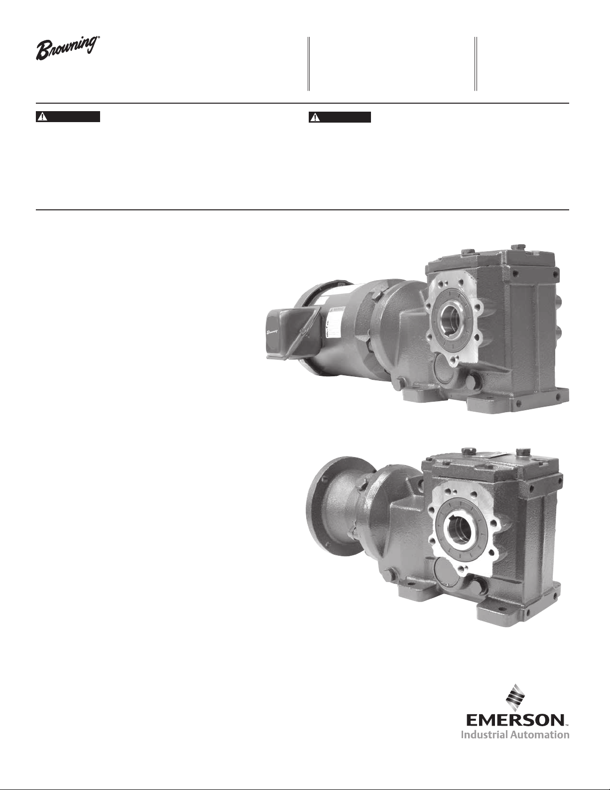
OtN Series 3000
CAUTION
WARNING
Gearmotors and Reducers
Emerson Industrial Automation
7120 New Bufngton Road
Florence, KY 41042
Application Engineering: 800 626 2093
www.PowerTransmissionSolutions.com
F O R M
9020E
Revised
January 2014
• Read and follow all instructions carefully.
• Disconnect and lock-out power before installation and maintenance.
Working on or near energized equipment can result in severe injury or death.
• Avoid contact with energized circuits or rotating parts.
• Be sure shaft key is fully captive before unit is energized.
• Do not operate equipment without guards in place. Exposed equipment can
result in severe injury or death.
• Periodic inspections should be performed. Failure to perform proper maintenance
can result in premature product failure and personal injury.
• All electrical work should be performed by qualied personnel and compliant with
local and national electrical codes.
Thank you for choosing an OtN Series 3000 gearmotor or reducer.
Installation Instructions
Start-Up
• Before operating the reducer or gearmotor, the following
must be done:
• If foot or ange mount, install the drive on a rigid
and vibration-free surface. If shaft mounted, install
the drive onto a rigidly supported drive shaft.
• Remove the protective coating on the shaft and
ange. Use solvent if necessary.
• Carefully install coupling, sheaves, sprockets, or pinions on
shaft. Mount as close to the shaft shoulder as possible.
• It is preferable to use heat instead of force. Do not hammer
on shaft!
• Check shaft alignment when using direct coupling.
• Check shaft parallelism when using belt or chain drive.
CAUTION : Refer to belt manufacturer’s recommendation
for belt tension. (Tension should not be applied on chain
drives.)
• Check oil level in oil lubricated reducer.
• Install breather plug in the plug hole per recommendations
shown on page (5).
Maintenance
To provide safe operation and to avoid problems, it is
recommended the reducer or gearmotor be inspected every 50
hours of operating time.
• Check mounting bolts and belt tension (if applicable).
The preventative maintenance list below should be performed
every 5000 hours of operating time:
• Check oil level and add oil if necessary.
• Make sure the vent hole in the breather is clean
Browning, Emerson and Emerson Industrial Automation are trademarks of Emerson
Electric Co. or one of its affiliated companies.
©2007, 2009, 2010, 2011, 2012, 2014 Emerson Power Transmission, All Rights Reserved.
MCIM14001E • Form 9020E • Printed in USA
1
Page 2
Combined Reduction
Lubricants
Series 3000 OtN gearing is shipped with one of the following synthetic lubricants per the table below and tted with a magnetic drain.
Each reducer is lled according to the mounting position specied when ordered. Refer to unit nameplate and the chart and table on
page 4 and 5 for mounting position arrangement for your unit.
In the case of synthetic oil, the lubricant does not require changing but it is recommended that proper oil level be checked periodically.
Standard Synthetic Gear Oil (Non - Food Grade)
No Backstop
Manufacturer
Fuchs* Sintogear
Mobil* Mobilgear
Shell* Omala
-25° F to 125° F
(-30° C to 50° C)
*
125
*
SHC 150
*
S4 GX 150
Standard Synthetic Gear Oil (Food Grade)
No Backstop
Manufacturer
22° F to 125° F
(-20° C to 50° C)
Mobil SHC Cibus 150
CAUTION: Never mix synthetic oil and mineral oil.
(1) Never use extreme pressure (EP) oil in a reducer with a backstop.
Acceptable Mineral Oil Lubricants
With Backstop (1)
Manufacturer
Shell Morlina S4 B 700
Mobil SHC 629
-25° F to 125° F
(-30° C to 50° C)
Ambient Range of Installation
-4°F to 14°F
(-20°C to 10°C)
14°F to 122°F (-10°C to 50°C)
No Backstop With Backstop (1)
122°F and Above
(50°C +)
ISO VG 68 ISO VG 100 ISO VG 150 ISO VG 220 ISO VG 150 ISO VG 320
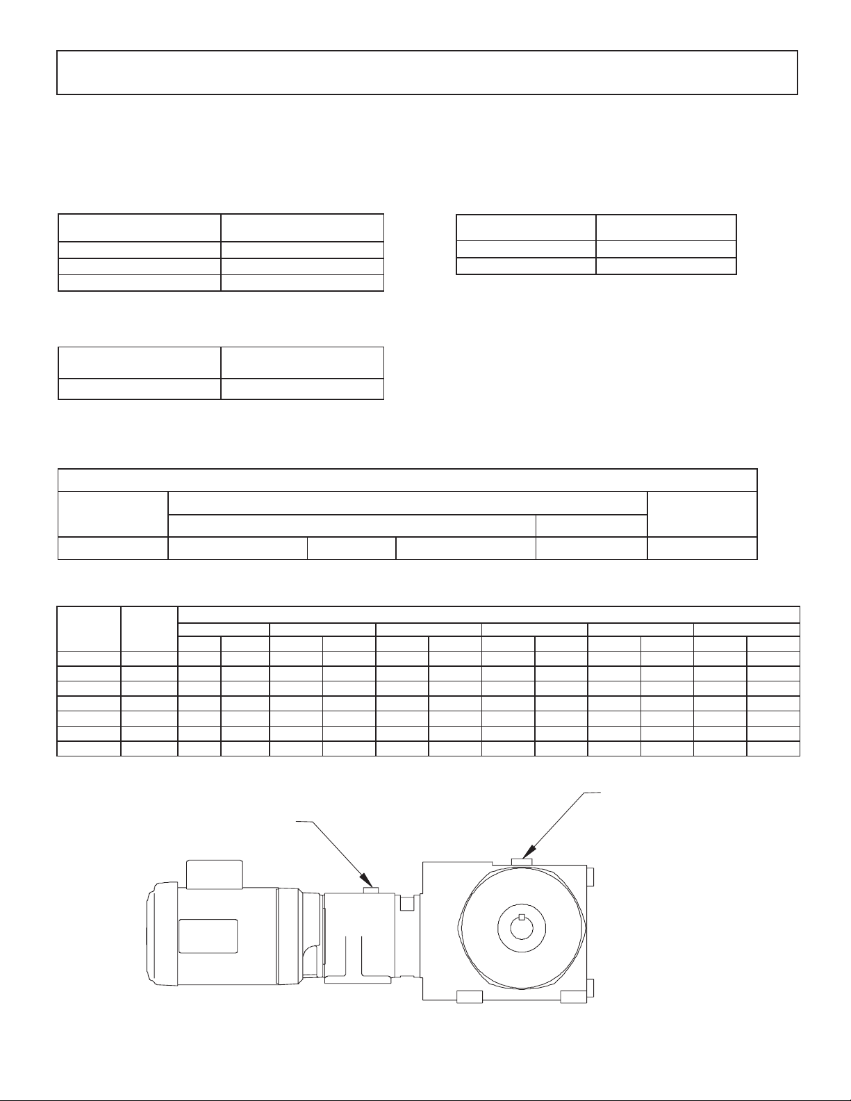
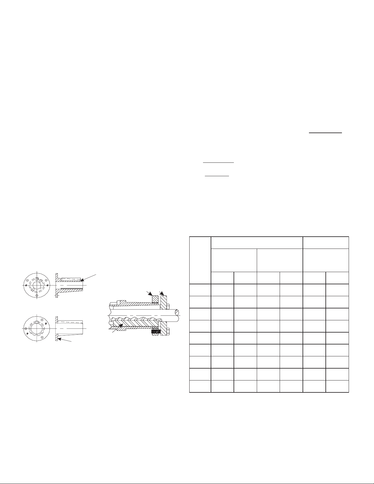
Combined OtN 3000 Gearing
Consists of an OtN primary gear housing and a CbN secondary gear housing. The table below provides the CbN oil volumes in quarts.
OtN
Frame
Size
3245 CbN 30 ** 0.64 ** 0.64 ** 0.64 ** 0.64 ** 0.64 ** 0.64
3365 CbN 31 ** 0.63 ** 1.16 ** 0.90 ** 1.00 ** 1.22 ** 1.48
3475/3476 CbN 31 ** 0.63 ** 1.16 ** 0.90 ** 1.00/1.30 ** 1.22 ** 1.48
3585/3586 CbN 31 ** 0.63 ** 1.16 ** 0.90 ** 1.00/1.30 ** 1.22 ** 1.48
3695/3696 CbN 32 ** 1.00 ** 2.38 ** 1.64 ** 1.85/2.43 ** 2.38 ** 2.85
3705/3706 CbN 32 ** 1.00 ** 2.38 ** 1.64 ** 1.85/2.43 ** 2.38 ** 2.85
3825/3826 CbN 32 ** 1.00 ** 2.38 ** 1.64 ** 1.85/2.43 ** 2.38 ** 2.85
Sec.
Gear
Size
B P H T V W
Prim. Sec. Prim. Sec. Prim. Sec. Prim. Sec. Prim. Sec. Prim. Sec.
** Refer to table on page 5 for the OtN oil volume based on frame size, Mounting Conguration, Mounting Position and Type of
Mounting ( i.e. Foot, Flange, etc.) of your unit.
Combined Reduction
Secondary
Mounting Position
Primary
* The following trade names, trademarks and/or registered trademarks are used in this material by Emerson Power Transmission Corporation are NOT owned or controlled by Emerson Power Transmission
Corporation and are believed to be owned by the following parties: Fuchs and Sintogear: Fuchs Corporation; Mobil and Mobilgear: Exxonmobil Oil Corporation; Shell and Omala: Shell Petroleum Incorporated.
Emerson Power Transmission Corporation cannot and does not represent or warrant the accuracy of this information.
2
Page 3
Plug Location and Oil Volume
10
S2 Conguration - All mounting styles
S1 Conguration - All mounting styles (except foot mounted 33, 34, and 35 – see below)
5
9
8
6
11
2
3
4
Mounting Position
Gear
Frame
Design
Plug Type
Size
Level 12
Drain 2 6 2 12 5 2
31 Breather 6 2 8*D 8*G 8 5
B P H T V W
Plug #
Oil Volume
Quarts
+
0.95
Plug #
12
Oil Volume
Quarts
+
1.06
Plug #
6
Oil Volume
Quarts
+
0.95
Plug #
6
Oil Volume
Quarts
+
0.8
Plug #
2
Oil Volume
Quarts
1.64
Fill 5 2 12 2 12 5
32 Drain 2 6 2 4 4 2
Double Reduction
Breather 6 2 4 2 8 5
Fill 5 2 4 2 2 5
1.96
Level 4
Level 4
32 Drain 2 5 2 8 5 8
Breather 6 3 4 3 8 5
0.55
4
2.06
4
1.82
6
1.74
5
1.5
6
2.06
6
1.5
2
3.12
2
2
Fill 5 3 4 2 8 4
33 (A) Drain 2 5 2 4 5 8
Breather 6 4 4 3 4 5
1.16
Level 3
3
3.7
5
3.49
6
2.96
2
3.96
Fill 5 2 4 2 2 4
34 Drain 2 5 2 4 or 8 5 8
Breather 6 3 4 3 8 5
1.37
Level 3
3
6.45
5
5.39
6
4.65
2
6.76
Fill 5 2 4 2 8 5
35 Drain 2 5 2 8 5 8
Breather 6 3 5 3 8 5
2.85
Level 3
3
8.88
6
5.39
6
7.72
2
11.42
Fill 5 2 5 2 8 5
Triple Reduction
36 Drain 2 5 3 4 5 2
Level 5**
Breather 5 10 4 3 11 9
6.08
10**
19.24
4**
14.28
3**
12.9
11**
23.36
Fill 5 10 4 3 11 9
37 Drain 2 5 3 4 5 2
Breather 5 10 4 3 11 9
10.58
Level 5**
10**
25
4**
20.3
3**
17.97
11***
35.94
Fill 5 2 4 3 11 9
Level 5**
38
Drain 11 5 3 4 5 2
Breather 5 10 4 3 11 9
10.57
10**
34.87
4**
29.06
3**
22.19
11**
43.32
Fill 5’ 11 4 3 11 9
3
2
+
Plug #
6
6
6
6
6
6
9**
9**
9**
4
Oil Volume
Quarts*
1.11
2.48
1.4
2.75
3.91
6.61
13.95
25.05
25.36
S1 Congurations 33D,33G,33X for Frames 33,34 and 35.
See above for all other mounting.
Gear
Frame
Size
33
Plug
Type
Level 3
Draining 6 2 4 2 5 8
Breather 2 6 3 4 4 5
B P H T V W
Plug#Oil Volume
Quarts
Plug#Oil Volume
+
Quarts
Plug#Oil Volume
+
3
3.7
1.16
Filling 2 5 2 4 2 4
34
Level 3
Draining 6 2 4 or 8 2 5 8
Breather 2 6 3 5 8 5
6.45
3
1.37
Filling 2 5 2 5 8 5
Level 3
35
+
Adaptor is assembled to position breather location on top when mounted in this position
** This is location for dipstick to check oil level
*** This location for dipstick with extension added to check oil level
Draining 6 2 8 2 5 8
Breather 2 6 3 5 8 5
8.88
Filling 2 5 2 5 8 5
3
2.65
Mounting Position
Quarts
6
2.96
6
4.65
6
7.72
Plug#Oil Volume
+
5
6
6
Quarts
3.49
5.39
5.39
8
Plug#Oil Volume
+
5
6
Plug#Oil Volume
+
Quarts
2
6
3.96
2
6
6.76
2
6
11.42
Quarts
2.75
3.91
6.61
+
3
Page 4
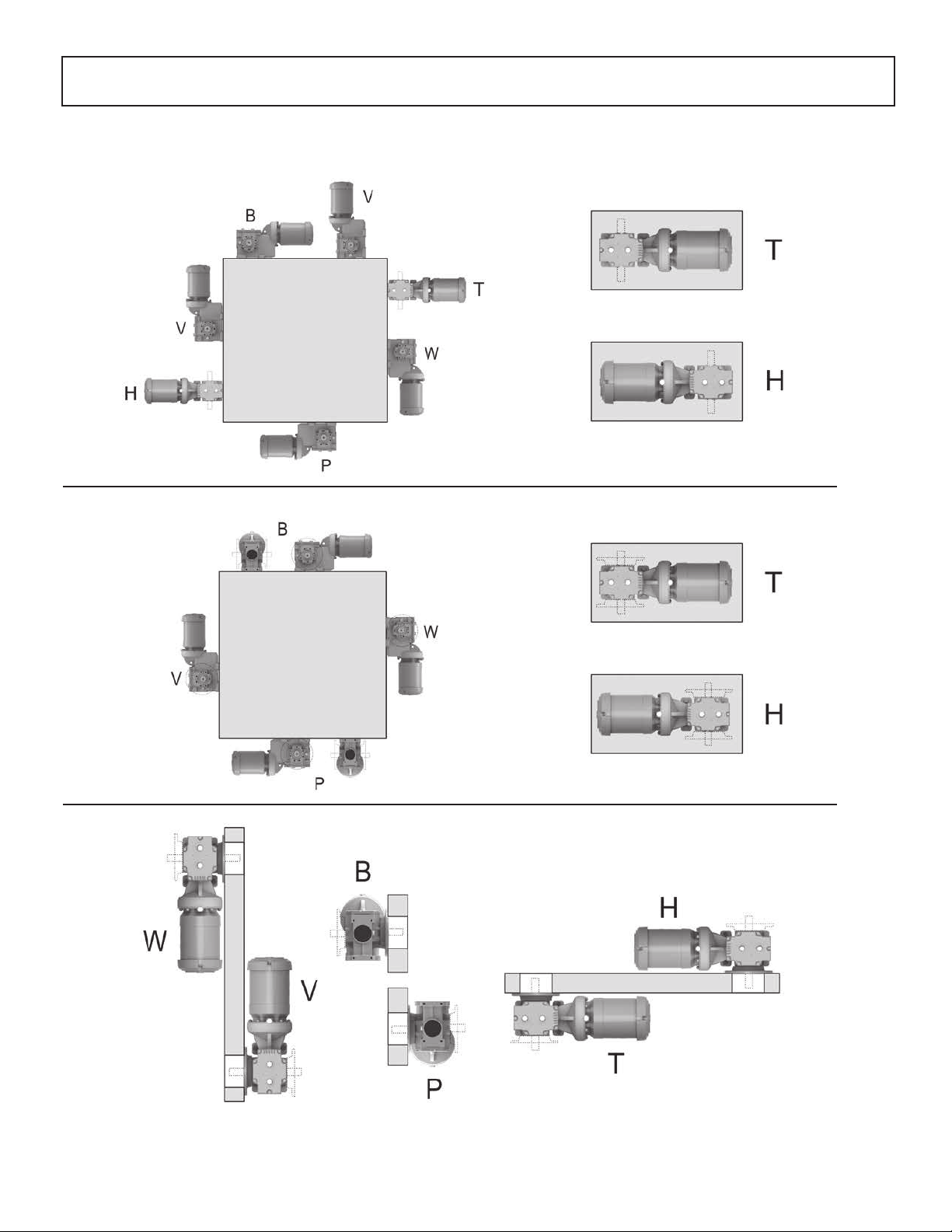
Gearbox Mounting Positions
Foot Mount
Foot Mount with Face or Flange
Flange, Face or Shaft Mount
4
Page 5
1. OtN Shaft Mount Reducer Installation
For long service and dependable performance, an OtN shaft
mounted gear unit must be properly supported and accurately
aligned. The following instructions are a step-by-step guide to
meeting these requirements for an OtN 3000 design shaft mounted
product. If there is a need to vary or deviate from any of these
installation instructions, contact Application Engineering Department
at 1-800-626-2093 before completing the installation.
CAUTION: When the driven shaft is smaller than the maximum
bushing size for a gear frame, check the driven shaft and key
stress per ANSI/AGMA Std. 6001-D97 for the application.
1.1 Reducer and Driven Shaft Preparation
1.1.1 The driven shaft diameter is to be within the commercial
tolerances for turned, ground and polished bars. The key and
keyseat in the driven shaft are to be in accordance with commercial
standards for the size, depth, offset, and parallelism.
1.1.2 The driven shaft on which the gear unit is to be mounted must
be straight, clean, and free of burrs.
1.1.3 Rotate the driven shaft on which the gear unit is to be mounted
so that the shaft keyseat is in the upward position.
1.1.4 A lifting lug is provided to lift the gear reducer or gearmotor
into position.
WARNING! Never lift the gear unit by the input or output
shaft. The lifting lug is designed for lifting only the gear reducer
or gearmotor. Do not use the lifting lug to lift attached assemblies.
Do not apply grease, oil, or any anti-seize compounds to the taper
bore of the reducer, barrel of the bushing, driven shaft or the bushing
bore. If any of these substances are applied, equipment failure and
personal injury may result.
1.2 Determine Mounting Conguration – Bushed Bore Models
Due to the unique design of OtN bushed shaft mounted product,
the reducer may be mounted to the driven shaft in a variety of
congurations. The following instructions will help to determine the
correct mounting conguration based on the available shaft and
key length
1.2.1 Measure the available driven shaft length “H” (in inches)
starting with the end of the driven shaft to the rst obstruction or
point of interference.
1.2.2 Measure the length of available keyseat “K” in the driven
shaft (in inches) starting from the end of the shaft to the end of the
useable keyseat.
1.2.3 The following sections 1.3, 1.4, 1.5 show the three standard
mounting congurations for the Browning
®
OtN tapered bushed
“33B” gearing. Refer to the following sections in sequence to
determine the optimum mounting conguration for your application.
1.2.4 Compare the measured values of H and K of the driven shaft
to the tabulated values of H and K. If the measured values for H and
K are greater than the tabulated values, the mounting conguration
shown in the gure may be used. If the measured values for H and
K are less than the tabulated values, proceed to the next gure
and repeat this step.
Note: If the measured values for H and K are less than the
tabulated values shown in 1-5, contact the Application Engineering
Department at 1-800-626-2093.
1.2.5 Tightening torque for bushing components.
Table 1.2.5
33B Taper Bushed Screw Conveyor
EXTERNAL KEY FURNISHED
TYPE 1
BUSHING
TYPE 2
BUSHING
THROUGH KEY FURNISHED
Figure 1-1
BUSHING
FLANGE
EXTERNAL KEY
KEY SHOWN
FOR TYPE 2
BUSHING
BUSHING
RING
TYPE 2
BUSHING
Figure 1-2
BUSHING
Gear
Frame
Tapered
Bushing Cap
screws
End Cap
Setscrews
(nylon tipped)
Keeper
Bolts
Size Ft.-Lbs Size In-Lbs Size Ft.-Lbs
31 5/16-18 16 1/4-20 60 - -
32 5/16-18 16 1/4-20 60 1/2-13 99
1
5/16-18 16 1/4-20 60 1/2-13 99
33
33A 3/8-16 29 1/4-20 60 - -
34 3/8-16 29 1/4-20 60 5/8-11 200
35 3/8-16 29 1/4-20 60 3/4-10 350
36 3/8-16 29 1/4-20 60 3/4-10 350
37 1/2-13 70 1/4-20 60 1-8 600
38 1/2-13 70 1/4-20 60 1-8 600
1
This design is replaced by 33A design effective Jan. 2010 for 33B output
5
Page 6
1.3 Mounting Conguration with Bushing Outboard
of Load
H
MC
Endcap
Driven
Stabilizer Ring
Shaft
Bushing
Ring
Driven
Shaft Key
Bushing
K
Figure 1-3
Table 1-3 Dimensions for Mounting Conguration
with Bushing Outboard of Load
Minimum Shaft
Mounting
Length
Gear
Frame
End cap
Clearance
MC H K
31 0.85 8.23 2.88
32 0.97 9.28 4.38
33
1
0.97 9.21 4.38
33A 1.03 11.16 4.63
34 1.03 11.34 4.63
35 1.21 12.23 5.63
36 1.31 16.75 6.13
37 1.44 18.08 7.38
38 1.69 18.43 7.38
1
This design is replaced by 33A design effective Jan. 2010
1.3.1 On the input shaft side, thread the bushing ring onto the
hollow reducer quill until the bushing ring is ush with the end of
the reducer quill shaft.
1.3.2 Place the end cap on the driven shaft with the threaded bore
facing the end of the shaft. Slide the stabilizer ring on the driven
shaft with the small end of the taper toward the end of the shaft.
1.3.3 Install Key(s)
Type 1 Bushing (2 keys):
• Install the external bushing key into the bushing as shown in
Figure 1-1 (external bushing key is supplied with the bushing kit)
• Install the driven shaft key (customer supplied) into the driven
shaft keyseat. Position the end of the driven shaft key even with
the end of the driven shaft. Retain this key to prevent movement.
1.3.4 Install Reducer
Type 1 Bushing
• Mount the reducer on the driven shaft with the bushing ring
facing outward toward the end of the driven shaft
6
Minimum Key
Connection
Length
• Locate the reducer on the driven shaft such that approximately
.50 inch of the driven shaft extends out beyond the end of the
reducer quill.
• Start the bushing (small end rst) by aligning the keyway in the
bushing with the key previously installed in the driven shaft.
• Continue moving the bushing into position and rotate the input
of the reducer as required to align the external bushing key with
the keyway in the reducer quill.
• Rotate the bushing ring clockwise to align the clearance holes
in the bushing with the threaded holes in the bushing ring. (This
will require less than 1/2 turn of the bushing ring).
• Install the bushing cap screws and hand tighten. Reposition
the reducer until the end of the driven shaft is even with the
end of the bushing ring.
• Slide the stabilizer ring into the reducer quill and thread the
end cap on hand tight.
• Tighten the bushing cap screws evenly around the bushing
ange to the recommended torque as shown Table 1.2.5. See
bolt torque specications section.
• Tighten the end cap again until hand tight. Tighten the setscrew
in the end cap to the recommended torque from Table 1.2.5.
Type 2 Bushing
• Mount the reducer on the driven shaft with the bushing ring
facing outward toward the end of the driven shaft.
• Rotate the input of the reducer as required to align the external
bushing key with the keyway in the reducer quill.
• Locate the reducer on the driven shaft such that approximately
.50 inch of the driven shaft extends out beyond the end of the
reducer quill.
• Start the bushing (small end rst) by aligning the keyway in the
bushing with the key previously installed in the driven shaft.
• Rotate the bushing ring clockwise to align the clearance holes
in the bushing with the threaded holes in the bushing ring. (This
will require less than 1/2 turn of the bushing ring).
• Install the bushing cap screws and hand tighten. Reposition
the reducer until the end of the driven shaft is even with the
end of the quill.
• Slide the stabilizer ring into the reducer quill and thread the
end cap on hand tight.
• Tighten the bushing cap screws evenly around the bushing
ange to the recommended torque as shown in Table 1.2.5.
• Tighten the end cap again until hand tight. Tighten the setscrew
in the end cap to the recommended torque from Table 1.2.5.
Note: The key length must be sufcient to engage the full length of
the bushing. The shaft must engage the full length of the reducer
shaft (Refer to “H” in Figure 1-3).
Note: There are three (3) series of bushing keys used in the
Type 2 bushing system: rectangular, square and offset. In most
cases, the key supplied will be rectangular or offset. Use caution
when installing rectangular keys as some may visually appear
square. The key should install in the bushing keyway with a sliding
type t. The key in the driven shaft keyseat should be retained
to prevent movement.
WARNING! The cap screws must thread into the bushing ring and
not the bushing. Threaded holes in the bushing are for removal
only. If assembled incorrectly, equipment failure and personal
injury may result.
Page 7
1.4 Mounting Conguration with Bushing on Load
Side of Reducer and Using Stabilizer Ring
H
Endcap
Dirt
Cover
Stabilizer
Ring
J
K
MC
Bushing Ring
Bushing
Driven
Shaft
Driven
Shaft Keyseat
Figure 1-4
Table 1-4 Dimensions for Mounting Conguration
with Bushing on Load Side of Reducer and
Using Stabilizer Ring
Minimum
Gear
Frame
Bolt
Clearance
Shaft
Mounting
Length
MC H K J
31 1.50 9.11 2.88 4.73
32 1.75 10.54 4.38 4.28
1
33
1.75 10.47 4.38 4.21
33A 1.88 12.23 4.63 5.83
34 1.88 12.51 4.63 6.01
35 1.88 13.13 5.63 5.62
36 1.88 17.50 6.13 9.49
Minimum
Key
Connection
Length
Max.
Note: Key length must be sufcient to engage the full length of
the bushing. The shaft must engage the full length of the bushing.
1.4.2 For Type 2 bushings which require one through key:
Install the bushing on the shaft, anged end rst. Align the keyway
in the bushing with the keyseat in the shaft and install the shaft key.
Position the shaft key ush against the inside ange surface of the
bushing. See Figure 1-2 Shaft Key and Bushing Location.
Note: There are three (3) series of bushing keys used in the Type
2 bushing system: rectangular, square and offset. In most cases,
the key supplied will be rectangular or offset. Use caution when
installing rectangular keys as some may visually appear square.
The key should install in the bushing keyway with a sliding type
t. The key in the driven shaft keyseat should be retained to
prevent movement.
Note: The shaft must be engaged the full length of the bushing.
1.4.3 On the side where the driven shaft enters, thread the bushing
ring onto the hollow quill until the bushing ring is ush with the end
of the hollow shaft. Rotate the gear unit input to align the keyway in
the hollow quill with the bushing/shaft key. Position the reducer on
the shaft with the bushing ring toward the bushing.
1.4.4 Slide the stabilizer ring onto the driven shaft with the small end
of the taper toward the reducer. Insert the stabilizer ring into the quill.
1.4.5 Thread the end cap and the dirt cover (not used if driven shaft
extends beyond the end of the hollow quill) onto the hollow quill until
hand tight. Do not tighten the end cap.
1.4.6 Rotate the bushing ring clockwise until the tapped holes align
with the drilled holes in the bushing ange. Prior to tightening the cap
screws, make sure the bushing key is as close as possible to the
inside ange of the bushing as shown in Figure 1-2 and the bushing
is positioned on the shaft as required in Figure 1-4. Dimensions for
rear mounting conguration with the stabilizer ring.
1.4.7 Install the bushing cap screws and tighten all the cap
screws evenly around the bushing ange to the required
torque. See bolt torque specications Table 1.2.5.
1.4.8 Tighten the end cap again until hand tight. Tighten
the setscrews to the recommended torque. See bolt torque
specications Table 1.2.5.
37 2.25 19.76 7.38 10.13
38 2.75 19.05 7.38 7.74
1
This design is replaced by 33A design effective Jan. 2010
1.4.1 For Type 1 bushings which require an external key and a
shaft key: Install the key (supplied with the bushing) in the external
keyseat of the bushing as shown in Figure 1-1. Install the shaft key
(not supplied) in the shaft keyseat and retain to prevent movement.
Install the bushing onto the shaft, anged end rst, align the bushing
keyway with the shaft key and position the bushing over the key.
WARNING! The cap screws must thread into the bushing ring
and not the bushing. Threaded holes in the bushing are for
removal only. If assembled incorrectly, equipment failure and
personal injury may result.
7
Page 8

1.5 Mounting Conguration with Bushing on Load
Side of Reducer and without Stabilizer Ring
H
K
Endcap
Driven
Shaft Keyseat
MC
Figure 1-5
Table 1-5 Dimensions for Conguration with bushing
on Load Side and no Stabilizer Ring
Minimum Shaft
Mounting
Length
Gear
Frame
Bolt
Clearance
MC H K
31 1.50 4.38 2.88
32 1.88 6.25 4.38
33 1.88 6.25 4.38
33A 1.88 6.50 4.63
34 1.88 6.5 4.63
35 1.88 7.5 5.63
36 1.88 8 6.13
Minimum Key
Connection
Length
1.5.1 For Type 1 bushings which require an external key and
a shaft key: Install the key (supplied with the bushing) in the
external keyseat of the bushing as shown in Figure 1-1. Install
the shaft key (not supplied) in the shaft keyseat and retain to
prevent movement. Install the bushing onto the shaft, anged
end rst, align the bushing keyway with the shaft key and position
the bushing over the key.
Note: Key length must be sufcient to engage the full length
of the bushing. The shaft must engage the full length of the
bushing.
1.5.2 For Type 2 bushings which require one through key:
Install the bushing on the shaft, anged end rst. Align the
keyway in the bushing with the keyseat in the shaft and install the
shaft key. Position the shaft key ush against the inside ange
surface of the bushing. See Figure 1-2 Shaft Key and Bushing
Location.
Note: There are three (3) series of bushing keys used in the
Type 2 bushing system: rectangular, square and offset. In
most cases, the key supplied will be rectangular or offset. Use
caution when installing rectangular keys as some may visually
appear square. The key should install in the bushing keyway
with a sliding type t. The key in the driven shaft keyseat
should be retained to prevent movement.
Note: The shaft must be engaged the full length of the
bushing.
1.5.3 On the side opposite the driven shaft entry, thread the
bushing ring onto the hollow quill until the bushing ring is ush
with the end of the hollow shaft. Rotate the gear unit input to align
the keyway in the hollow quill with the bushing/shaft key. Position
the reducer on the shaft with the bushing ring toward the bushing.
1.5.4 Thread the end cap and the dirt cover (not used if driven
shaft extends beyond the end of the hollow quill) onto the
hollow quill until it bottoms out. Tighten the setscrew to the
recommended torque. See bolt torque specications Table 1.2.5.
1.5.5 Rotate the bushing ring clockwise until the tapped
holes align with the drilled holes in the bushing ange. Prior to
tightening the cap screws, make sure the bushing key is as close
as possible to the inside ange of the bushing as shown in Figure
1-2 and the bushing is positioned on the shaft as required in
Table 1-5. Dimensions for rear mounting conguration with the
stabilizer ring.
1.5.6 Install the bushing cap screws and tighten all the cap screws
evenly around the bushing ange to the required torque. See bolt
torque specications Table 1.2.5.
37 2.25 9.75 7.38
38 2.75 11.31 7.38
8
WARNING! The cap screws must thread into the bushing ring and
not the bushing. Threaded holes in the bushing are for removal
only. If assembled incorrectly, equipment failure and personal
injury may result.
Page 9

Taper Bushing Selection
Each Series 3000 OtN can be ordered with an inch or metric Tapered
Bushed Output. This “33B” mounting conguration will include the
appropriate bushing kit when a bore is dened at order entry. The
table below shows the various stocked bushing bores for each
OtN frame that can be specied. Each bushing kit is supplied with
bushing, hardware for mounting and a stabilizer ring unassembled. If
bushings are required as a spare or bore changed in the eld, refer
to the OtN 3000 frame and bore to select the required kit below.
OtN
Frame
Meas.
Unit
Bushing
Number
Bore
1
Shaft Keyseat
Required
Type
OtN
Frame
Meas.
Unit
Bushing
Number
Bore
1
Shaft Keyseat
Required
Type
105TBP100 1” 1/4 x 1/8 x 2 1/2 2
Inch
31
Metric * 105TBP30MM 30 mm 8 x 3.5 x 65 (mm) 2
Inch
32
&
33
Metric *
Inch
33A
Metric *
Inch
34
Metric * 115TBP45MM 45 mm 14 x 4.5 x 105 (mm) 2
1
Bushing bore shown must be selected by customer based on
105TBP103 1 3/16” 1/4 x 1/8 x 2 1/2 2
105TBP104 1 1/4” 1/4 x 1/8 x 2 1/2 2
105TBP105 1 5/16” 5/16 x 5/32 x 2 1/2 2
107TBP105 1 5/16” 5/16 x 5/32 x 3 7/8 2
107TBP106 1 3/8” 5/16 x 5/32 x 3 7/8 2
107TBP107 1 7/16” 3/8 x 3/16 x 3 7/8 2
107TBP30MM 30 mm 8 x 3.5 x 100 (mm) 2
107TBP35MM 35 mm 10 x 4 x 100 (mm) 2
115TBP107 1 7/16 3/8 x 3/16 x 4 1/8 2
115TBP108 1 1/2 3/8 x 3/16 x 4 1/8 2
115TBP110 1 5/8 3/8 x 3/16 x 4 1/8 2
115TBP111 1 11/16 3/8 x 3/16 x 4 1/8 2
115TBP112 1 3/4 3/8 x 3/16 x 4 1/8 2
115TBP114 1 7/8 1/2 x 1/4 x 4 1/8 2
115TBP115 1 15/16 1/2 x 1/4 x 4 1/8 2
115TBP40MM 40 mm 12 x 4 x 105 (mm) 2
115TBP45MM 45 mm 14 x 4.5 x 105 (mm) 2
115TBP111 1 11/16 3/8 x 3/16 x 4 1/8 2
115TBP112 1 3/4 3/8 x 3/16 x 4 1/8 2
115TBP114 1 7/8 1/2 x 1/4 x 4 1/8 2
115TBP115 1 15/16 1/2 x 1/4 x 4 1/8 2
complete application details
* Metric bushings have metric bores and require metric keyseats
as shown in mm.
207TBP200 2 1/2 x 1/4 x 5 1/8 2
207TBP202 2 1/8 1/2 x 1/4 x 5 1/8 2
Inch
35
Metric *
Inch
36
Metric *
Inch
37
Metric *
Inch
38
Metric * 315TBP90MM 90mm 25 x 7 x 190 (mm) 2
207TBP203 2 3/16 1/2 x 1/4 x 5 1/8 2
207TBP204 2 1/4 1/2 x 1/4 x 5 1/8 2
207TBP207 2 7/16 5/8 x 5/16 x 5 1/8 2
207TBP50MM 50 mm 14 x 4.5 x 130 (mm) 2
207TBP60MM 60 mm 18 x 5.5 x 130 (mm) 2
215TBP207 2 7/16 5/8 X 5/16 X 5 5/8 2
215TBP208 2 1/2 5/8 X 5/16 X 5 5/8 2
215TBP211 2 11/16 5/8 X 5/16 X 5 5/8 2
215TBP215 2 15/16 3/4 X 3/8 X 5 5/8 2
215TBP60MM 60 mm 18 x 5.5 x 140 (mm) 2
215TBP70MM 70 mm 20 x 6 x 140 (mm) 2
307TBP214 2 7/8 3/4 x 3/8 x 6 3/4 2
307TBP215 2 15/16 3/4 x 3/8 x 6 3/4 2
307TBP300 3 3/4 x 3/8 x 6 3/4 2
307TBP306 3 3/8 7/8 x 7/16 x 6 3/4 2
307TBP307 3 7/16 7/8 x 7/16 x 6 3/4 2
307TBP75MM 75 mm 20 x 6 x 170 (mm) 2
307TPB80MM 80 mm 22 x 7 x 170 (mm) 2
307TBP85MM 85 mm 22 x 7 x 170 (mm) 2
315TBP215 2 15/16 3/4 x 3/8 x 7 15/16 2
315TBP300 3 3/4 x 3/8 x 7 15/16 2
315TBP303 3 3/16 3/4 x 3/8 x 7 15/16 2
315TBP307 3 7/16 7/8 x 7/16 x 7 15/16 2
315TBP315 3 15/16 1 x 1/2 x 7 15/16 2
9
Page 10

NOT SUPPLIED
REMOVAL
Finished Bore Mounting
1.6 Mounting Of Reducer with Finished Bore Shaft
1.6.1 Check the internal bore of the reducer and make sure the
snap ring and washer are in the end of the shaft bore opposite
the entry side of the driven shaft.
1.6.2 Check the driven shaft to make sure it is free from
burrs and any rust preventative coating. Lubricate the driven
shaft to ease mounting with reducer. (Anti-Fretting grease is
recommended only for nished bore designs). A lifting lug is only
for lifting the weight of the reducer/gearmotor.
WARNING! (Do not use the lifting lug on the gear housing to
lift additional attached assemblies to avoid overloading the
lifting lug). Never lift gear unit by its output shaft.
1.6.3 Check the driven shaft to ensure the end is tapped. Install
the shaft key in the keyseat.
1.6.4 Rotate the OtN input until the hollow output shaft is aligned
with the key in the driven shaft.
1.6.5 The OtN gear shaft is mounted on the driven shaft using a
threaded rod, and screwed into the shaft.
By then threading a nut down onto the washer in the reducer
shaft, the shaft is smoothly inserted into the cylindrical bore of the
reducer shaft.
1.6.6 Replace the threaded rod with the bolt that is supplied with
the OtN unit. Thread it into the driven shaft and tighten to the
required torque. See bolt torque as shown in Table 1.2.5.
1.6.7 Install the hollow shaft cover onto the gear housing
opposite the driven shaft with the two (2) screws provided with
the cover.
1.6.8 Drive Shaft Recommendations - Its best to use the keeper
bolt to pull the driven shaft into the quill up against a shoulder on
the driven shaft.
NOT
SUPPLIED
MOUNTING
1.7 Dismounting of the Reducer from driven shaft
1.7.1 Secure the reducer weight.
1.7.2 Thread in a long bolt that has the same thread design as
the threaded core of the reducer shaft’s washer (see Table 7-1
below). By tightening down that bolt, the driven shaft will be
separated smoothly from the reducer shaft bore.
Key
UF U
UY
Gear
Frame
1
the key for the frame 34 is supplied by Browning
Version
31 S2 5.12 1.250 1.77 1.372 4.31 0.37 1/4 x 1/4 x 1-1/2 7/16-14 x 1.00 5/8
32
33 S2 6.94 1.500 2.16 1.674 5.96 0.49 3/8 x 3/8 x 2-1/4 5/8-11 x 1.75 3/4
34 S2 8.97 2.000 2.56 2.210 7.44 0.72 1/2 x 7/16 x 2-5/8 5/8-11 x 1.75 3/4
35 S2 9.66 2.375 3.54 2.638 8.15 0.85 5/8 x 5/8 x 3-3/8 3/4-10 x 2.0 7/8
36 S2 12.44 2.750 3.93 3.037 10.89 1.23 5/8 x 5/8 x 5-1/2 3/4-10 x 2.0 1
37 S2 13.59 3.625 4.72 4.019 11.9 1.23 7/8 x 7/8 x 5-1/2 3/4-10 x 2.0 1
38 S2 13.74 4.00 5.50 4.316 11.69 1.58 1 x 1 x 6 1-8 x 2.5 1.25
S2 5.94 1.375 1.96 1.523 5.06 0.37 5/16 x 5/16 x 1-13/16 1/2-13 x 1.00 5/8
S3 5.94 1.250 1.96 1.372 5.19 0.37 1/4 x 1/4 x 1-13/16 7/16-14 x 1.00 5/8
Output Shaft
Reducer Shaft Driven Shaft
EH U UF UY VG MH Key
EH
M
VG
MH
1
M (inches)
Keeper Washer
Thread UNC
10
Page 11

Torque Arm Assembly Instructions
Mounting Instructions
1. For Series 3000, mount the torque arm as shown in Figure 5 to side of the reducer where the driven shaft enters. Apply Loctite*
432 or equal to the threads of each bolt before assembly.
2. Connect the reducer to the driven shaft.
3. Attach torque arm to the mounting plate or attachment point.
4. Tighten the cap screws to the recommended torque.
Series 3000 Torque Arm Kits
Table 1
Table 2
OtN Frame Kit Part ID#
31 ROC100KT001
32 ROC200KT001
33 ROC300KT001
34 ROC400KT001
35 ROC500KT001
36 ROC600KT001
37 ROC700KT001
38 ROC800KT001
Fastener Size Torque ( Ft. Lbs)
M10 49
M12 87
M16 220
M20 430
90°
Table 3
OtN Frame(s) Kit Hardware
Screws (4)
31 and 32
Roll Pin (1)
Screws (3)
33, 34, 35
Roll Pin (1)
Screws (4)
36 and 37
Roll Pin (1)
Screws ( 8 )
38
Roll Pin ( 2 )
180°
270°
* The following trade names, trademarks and/or registered trademarks are used in this material by Emerson Power Transmission Corporation are NOT owned or controlled by Emerson Power Transmission
Corporation and are believed to be owned by the following parties: LOCTITE: Henkel Corporation. Emerson Power Transmission Corporation cannot and does not represent or warrant the accuracy of
this information.
Figure 5
0°
Anchoring of the
Torque Arm
(Top View)
11
Page 12

TWO STAGE OtN SERIES 3000
OtN SERIES 3000 GEARMOTORS AND REDUCER
282
254
193
2
99
251
254
264
130
113
120
61
51
76
77
31
62
121
151
131
91
3
213
187
31
128
127
126
51
62
131
91
255
284
1
1
257
132
115
118
41
80
63
148
64
155
154
90
122
130
61
93
9
129
125
76
153
117
111
138
52
2
139
12
76
31
123
124
3
123
Page 13

Parts List - Two Stage Frames 31 and 32
Qty Per Frame
Item # Description
31 32
1 Main housing 1 1
2 Top cover 1 1
9 Output ange (primary) 1 1
10 Output ange (secondary) 1 1
15 Output shaft cover (hollow design) 1 1
31 Output shaft 1 1
41 Bevel pinion 1 1
51 Bevel Gear 1 1
52 Primary gear axis 2 1 1
61 Bearing axis 4 1 1
62 Bearing axis 4 1 1
63 Bearing axis 2 front 1 1
64 Bearing axis 2 rear 1 1
76 Key for gear 1 1
77 Output shaft key D or G 1 1
80 Key primary gear 1 1
90 Output oil seal left 1 1
91 Output oil seal right 1 1
93 Output seal - ange option 1 1
99 Top cover gasket 1 1
111 Shim 1 1
113 Spacer 1 1
115 Shim 1 1
117 Shim axis 2 rear 1 1
118 Shim axis 2 front 1 1
120 Bearing shim 1 1
121 Bearing shim 1 1
122 End cap for B design 1 1
Item # Description
123 Internal snap ring 2 2
124 Extraction washer 1 1
125 Stabilizer collar for B design 1 1
126 Bushing cap screws 3 3
127 Bushing for B design 1 1
129 Dust cover 1 1
130 Bearing snap ring axis #4 1 1
131 Bearing snap ring axis #4 1 1
132 Bearing snap ring axis 2 1 1
136 Snap ring MD axis 4 1 2
138 Bearing snap ring axis 2 1 1
139 Snap ring for primary gear 1 1
148 Spacer axis 2 1 1
151 Spacer 1 1
153 Snap ring axis 2 1 1
154 Washer axis 2 1 1
155 Shim axis 2 1 1
187 Flange bolts 4 6
193 Top cover screws 6 7
203 Cover screws for Rep #15 2 2
213 Flange roll pin 1 1
251 Bore Plug 0 1
254 Plain plugs 4 4
255 Breather 1 1
257 Magnetic drain plug 1 1
264 Bore plug axis 4 for D and G 1 1
282 Nameplate 1 1
284 Nameplate rivets 2 2
Qty Per Frame
31 32
Common Replacement Parts
Frame Size Shaft
G-D 32009 32009 45 x 75 x 8 *
31
32
* Bore plug utilized
X 32009 32009 45 x 75 x 8 45 x 75 x 8
C-B 6009 2RS 6009 2RS 45 x 75 x 8 45 x 75 x 8
G-D 32010 32010 50 x 80 x 10 *
X 32010 32010 50 x 80 x 10 50 x 80 x 10
C-B 6010 2RS 6010 2RS 50 x 80 x 10 50 x 80 x 10
Bearings Oil Seals
61 62 90 91
Top Cover Gasket
JOI156JN001
JOI185JN003
13
Page 14

THREE STAGE OtN SERIES 3000
OtN 32-35 Three Stages (Quantity Per Unit)
284
282
255
2
264
130
113
120
61
501
76
31
77
51
502
62
121
151
131
91
4
133
112
3
53
66
152
114
134
253
51
62
131
91
126
127
81
41
128
119
65
122
129
76
31
252
254
187
90
130
61
132
213
115
193
118
9
99
1
1
257
63
43
93
Ring sealed
reinforced option
148
166
165
80
64
155
117
154
111
153
138
139
2
52
14
332
4
125
124
123
31
90
76
130
61
303
51
62
76
121
131
91
305
325
76
301
331
300
330
302
Page 15

Parts List - Three Stage Frame 32 through 35
Item # Description
1 Main housing 1 1 1 1 129 Dust cover 1 1 1 1
2 Top cover 1 1 1 1 130 Bearing snap ring axis #4 1 1 1 1
9 Output ange (primary) 1* 1* 1* 1* 131 Bearing snap ring axis #4 1 1 1 1
10 Output ange (secondary) + 1* 1* 1* 1* 132 Bearing snap ring axis 2 1 1 1 1
15 Output shaft cover (hollow design) 1 1 1 1 133 Bearing snap ring axis 3 1 1 1 1
31 Output shaft 1 1 1 1 134 Snap ring axis #4 1 1 1 1
41 Pinion axis 3 1 1 1 1 136 Snap ring MD axis 4 2 2 2 2
43 Bevel pinion axis 2 1 1 1 1 138 Bearing snap ring axis 2 1 1 1 1
51 Gear axis 4 1 1 1 1 139 Primary gear xing snap ring 1 1 1 1
52 Gear axis 2 1 1 1 1 142 Primary Gear xing screw 0 0 0 0
53 Bevel gear axis 3 1 1 1 1 148 Spacer axis 2 1 1 1 1
61 Bearing axis 4 left 1 1 1 1 152 Shims axis 3 1 or 2 4 2 or 3 3
62 Bearing axis 4 right 1 1 1 1 153 Snap ring axis 2 1 1 1 1
63 Bearing axis 2 front 1 1 1 1 154 Washer axis 2 1 1 1 1
64 Bearing axis 2 rear 1 1 1 1 155 Shim axis 2 2 2 2 2
65 Bearing axis 3 right 1 1 1 1 165 Nut (rep 64) 0 0 0 0
66 Bearing axis 3 left 1 1 1 1 166 Lock washer (rep 165) 0 0 0 0
76 Key for axis 4 gear (rep 51) 1 1 1 1 187 Flange screws 4 6 6 6
77 Output shaft key D or G 1 1 1 1 193 Top cover screws 7 7 7 7
80 Key (prim. gear) 1 1 1 1 213 Roll pin (ange) 1 1 1 1
81 Key (rep. 53) 1 1 1 1 251 Bore Plug 0 1 0 0
90 Oil seal axis 4 right 1 1 1 1 252 Bore plug axis 3 left 1 1 1 1
91 Oil seal axis 4 left 1 1 1 1 253 Bore plug axis 3 right 1 1 1 1
93 Ring seal axis 4 (option) 1 1 1 1 254 Plain plugs 2 3 3 2
99 Top cover gasket 1 1 1 1 255 Breather plug 1 1 1 1
103 Oil deector 1 1 1 1 257 Magnetic Pipe Plug 1 1 1 1
111 Bearing spacer axis 2 1 1 1 1 261 Breather plug with dipstick 0 0 0 0
112 Bearing spacer axis 3 right 1 1 1 1 264 Bore plug axis 4 1 1 1 1
114 Bearing spacer axis 3 left 1 1 1 1 282 nameplate 1 1 1 1
115 Bearing spacer axis 2 front 1 1 1 1 284 nameplate rivets 2 2 2 2
117 Shim axis 2 rear 1 to 3 3 3 3 501 Nilos deector axis 4 (left) 0 0 0 0
118 Shim axis 2 front 1 to 3 3 3 3 502 Nilos deector axis 4 (right) 0 0 0 0
Shims axis 3 1 to 4 4 2 or 3 3
119
120 Bearing shim (SCD) 1 1 1 1
121 Bearing shim (SCD) 1 1 1 1
122 End cap 1 1 1 1
123 Snap ring 1 1 1 1
124 Extraction washer 1 1 1 1
125 Snap ring 1 1 1 1
126 Bushing capscrews 3 3 3 3
127 tapered bushing 1 1 1 1
128 Bushing collar 1 1 1 1
+ not illustrated in exploded view drawing
** there are (2) used on C, B shafts
*** not used on C, B shafts
Qty Per Frame
32 33 34 35 32 33 34 35
Item # Description
Qty Per Frame
Common Replacement Parts
Frame Size Shaft
G-D 6208 ZZ C3 6208 ZZ C3 40 x 80 x 10 *
32
C-B 6010 ZZ C3 6010 ZZ C3 50 x 80 x 8 50 x 80 x 8
G-D 6309 ZZ C3 6309 ZZ C3 45 x 100 x 8 *
33
C-B 6211 ZZ C3 6211 ZZ C3 55 x 100 x 10 55 x 100 x 10
33A C-B 6013 ZZ C3 6013 ZZ C3 65 X 100 X 10 65 x 100 x 10 JOI208JN002
G-D 6213 ZZ C3 6213 ZZ C3 65 x 120 x 10 *
34
C-B 6213 ZZ C3 6213 ZZ C3 65 x 120 x 10 65 x 120 x 10
G-D 6313 ZZ C3 6313 ZZ C3 65 x 140 x 12 *
35
C-B 6018 ZZ C3 6018 ZZ C3 90 x 140 x 11 90 x 140 x 11
* Bore plug utilized
Bearings Oil Seals
61 62 90 (mm) 91 (mm)
Top Cover Gasket
JOI161JN002X 6208 ZZ C3 6208 ZZ C3 40 x 80 x 10 40 x 80 x 10
JOI208JN002X 6309 ZZ C3 6309 ZZ C3 45 x 100 x 8 45 x 100 x 8
JOI247JN001X 6213 ZZ C3 6213 ZZ C3 65 x 120 x 10 65 x 120 x 10
JOI295JN002X 6313 ZZ C3 6313 ZZ C3 65 x 140 x 12 65 x 140 x 12
15
Page 16

THREE STAGE OtN SERIES 3000
OtN 36-38 Three Stages (Quantity Per Unit)
115
282
193
99
118
9
1
1
257
63
43
148
93
Ring sealed
reinforced option
166
165
80
64
155
117
154
111
153
138
139
2
52
284
255
2
264
130
113
120
61
501
76
31
77
51
502
62
121
151
131
91
4
133
112
3
53
66
152
114
134
253
51
62
131
91
126
127
81
41
128
119
65
122
129
76
31
252
254
187
90
130
61
132
213
16
4
125
124
123
76
31
Page 17

Parts List - Three Stage Frame 36 through 38
Item # Description
1 Main housing 1 1 1 128 Bushing collar 1 1 1
2 Top cover 1 1 1 129 Dust cover 1 1 1
9 Output ange (primary) 1 1 0 130 Bearing snap ring axis #4 1 1 1
10 Output ange (secondary) + 1 1 n/a 131 Bearing snap ring axis #4 1 1 1
15 Output shaft cover (hollow design) 1 1 1 132 Bearing snap ring axis 2 1 1 1
31 Output shaft 1 1 1 133 Bearing snap ring axis 3 1 1 1
41 Pinion axis 3 1 1 1 134 Snap ring axis #4 1 1 1
43 Bevel pinion axis 2 1 1 1 136 Snap ring MD axis 4 2 2 0
51 Gear axis 4 1 1 1 138 Bearing snap ring axis 2 1 1 1
52 Gear axis 2 1 1 1 139 Primary gear xing snap ring 1 0 1
53 Bevel gear axis 3 1 1 1 142 Primary Gear xing screw 0 1 0
61 Bearing axis 4 left 1 1 1 148 Spacer axis 2 1 1 1
62 Bearing axis 4 right 1 1 1 152 Shims axis 3 1 to 3 1 to 3 1 to 3
63 Bearing axis 2 front 1 1 1 153 Snap ring axis 2 0 0 0
64 Bearing axis 2 rear 1 1 1 154 Washer axis 2 0 0 0
65 Bearing axis 3 right 1 1 1 155 Shim axis 2 0 0 0
66 Bearing axis 3 left 1 1 1 165 Nut (rep 64) 1 1 1
76 Key for axis 4 gear (rep 51) 1 1 1 ** 166 Lock washer (rep 165) 1 1 1
77 Output shaft key D or G 1 1 1 187 Flange screws 7 9 11
80 Key (prim. gear) 1 1 1 193 Top cover screws 10 11 11
81 Key (rep. 53) 1 1 1 213 Roll pin (ange) 1 1 1
90 Oil seal axis 4 right 1 1 1 251 Bore Plug 0 0 0
91 Oil seal axis 4 left 1 1 1 252 Bore plug axis 3 left 1 1 1
93 Ring seal axis 4 (option) 1 1 0 253 Bore plug axis 3 right 1 1 1
94 O-ring seal axis 4 + 0 0 2*** 254 Plain plugs 5 5 4
95 Bearing carrier axis 4 + 0 0 2*** 255 Breather plug 0 0 0
99 Top cover gasket 1 1 1 257 Magnetic Pipe Plug 1 1 1
103 Oil deector 1 1 1 261 Breather plug with dipstick 1 1 1
111 Bearing spacer axis 2 1 1 1 264 Bore plug axis 4 1 1 1
112 Bearing spacer axis 3 right 1 1 1 282 nameplate 1 1 1
114 Bearing spacer axis 3 left 1 1 1 284 nameplate rivets 2 2 2
115 Bearing spacer axis 2 front 1 1 1 501 Nilos deector axis 4 (left) 1 1 1
117 Shim axis 2 rear 1 to 3 1 to 3 1 to 3 502 Nilos deector axis 4 (right) 1 1 1
118 Shim axis 2 front 1 to 3 1 to 3 1 to 3
119 Shims axis 3 1 to 3 1 to 3 1 to 3
120 Bearing shim (SCD) 1 1 0
121 Bearing shim (SCD) 1 1 0
122 End cap 1 1 1
123 Snap ring 1 1 1
124 Extraction washer 1 1 1
125 Snap ring 1 1 1
126 Bushing capscrews 3 3 1
127 Tapered bushing 1 1 1
+ not illustrated in exploded view drawing
** there are (2) used on C,B shafts
*** not used on C,B shafts
Qty Per Frame
36 37 38 36 37 38
Item # Description
Qty Per Frame
Common Replacement Parts
Frame Size Shaft
G-D 32020 32020 85 x 150 x 12 *
36
37
38
* Bore plug utilized
X 32020 32020 85 x 150 x 12 85 x 150 x 12
C-B 6020 ZZ 6020 ZZ 100 X 150 X 13 100 X 150 X 13
G-D 32024 32024 120 X 180 X 15 *
X 32024 32024 120 X 180 X 15 120 X 180 X 15
C-B 6024 ZZ 6024 ZZ 120 X 180 X 15 120 X 180 X 15
G-D 30220 30220 120 X 180 X 15 *
C-B 30228 30228 140 x 250 x 15 140 x 250 x 15
Bearings Oil Seals
61 62 90 91
Top Cover gasket
JOI414JN001
JOI475JN001
JOI475J N001X 30224 30224 120 X 180 X 15 120 X 180 X 15
17
Page 18

C - Face Input Parts List
OtN 31 - 38 Two and Three Stage (Quantity Per Unit)
12
8
18
6
5
4
3
17
2
7
1
16
15
14
9
10
11
19
13
No. Description 56C 140TC 180TC 210TC 250TC 280TC
1 Non-metallic Liner 1 1 1 1 1 1
2 Seal 1 1 1 1 1 1
3 Motor Adapter 1 1 1 1 1 1
4 Cap screw 6 6 6 6 6 6
5 Bearing 1 1 1 1 1 1
6 Spacer 1 1 1 1 1 1
7 Input Shaft 1 1 1 1 1 1
8 Bearing 1 1 1 1 1 1
9 Internal Snap Ring 1 1 1 1 1 1
10 Key* 1 1 1 1 1 1
11 Pinion 1 1 1 1 1 1
12 Nuts Q ** ** ** ** ** **
13 Studs Q ** ** ** ** ** **
14 Adapter Flange 1 1 1 1 1 1
15 Gasket 1 1 1 1 1 1
16 Plug *** 1 1 1 1 1 1
17 Motor Adapter Flange N/A N/A N/A N/A N/A 1
18 Backstop Kit (optional) 1 1 1 1 1 1
19 Nilos Seal 0 0 0 0 1 1
* Pin used with 9mm, 12mm, 15mm, and 18mm pinions
** Depending on gear frame and red.stages:Two stages 31=4, 32=5; Three stages 32,35=4 ,33=5,34=6, 36,37=8
*** For frames 31 through 35 these are 1/4” BSP, and 3/4” BSP on frames 36 and larger
Gear
Frame
31 to 35 56C , 140TC 6007 ZZ C3 6207 ZZ C3 2 x 1.375 x .312
32 to 37 180TC 6012 ZZ C3 6210 ZZ C3 4 x 2.250 x .468
33 to 38 210TC 6012 ZZ C3 6210 ZZ C3 4 x 2.250 x .468
35 to 38 250TC, 280TC 6014 ZZ C3 NJ210 4.438 x 2.625 x .437
18
Motor
Frame
5 8 2
Bearings Seal (inches)
Page 19

C-Face Coupling Input Parts List
OtN 36 - 38 Three Stage (Quantity Per Unit)
20
17
18
19
16
15
14
13
12
11
10
9
8
7
6
3
5
4
2
1
No. Description Of Part 320TC/360TC
1 Setscrew 1
2 Motor Coupling 1
3 Motor Adapter 1
4 Coupling Sleeve 1
5 Seal 1
6 Internal Snap Ring 1
7 Bearing 1
8 External Snap Ring 1
9 Adapter Flange 1
10 Capscrew 8
11 Backstop 1
12 Capscrew 12
13 Spacer 1
14 Bearing 1
15 Internal Snap Ring 1
16 Bearing Seal 1
17 Pinion 1
18 Key 1
19 External Snap Ring 1
20 Input Shaft 1
Gear
Frame
36 to 38 6216 ZZ C3 NJ310 140x110x12 (mm) nitrile
7 14 1
Bearings Seal
19
Page 20

AP Input Shaft Parts List
9
15
12
OtN 31 - 35 Two and Three Stage (Quantity Per Unit)
2
3
8
10
12
11
13
7
6
4
5
1
9
OtN 36 - 38 Three Stage
8
10
16
5
11
17
14
13
7
6
4
1
No. Description of Part
1 Seal 1 1 1 1 1 1 1
2 Nuts 4 5 4 5 6 4 0
3 Studs 4 5 4 5 6 4 0
4 Housing 1 1 1 1 1 1 1
5 External Snap Ring 1 1 1 1 1 1 1
6 Bearing 1 1 1 1 1 1 1
7 Spacer 1 1 1 1 1 1 1
8 Bearing 1 1 1 1 1 1 1
9 Input Shaft 1 1 1 1 1 1 1
10 Internal Snap Ring 1 1 1 1 1 1 1
11 Pinion 1 1 1 1 1 1 1
12 Key* 1 1 1 1 1 1
13 Backstop Kit (optional) 1 1 1 1 1 1 1
14 Spacer - - - - - - 1
15 Bolt - - - - - - 8
16 Bearing Seal - - - - - - 1
17 External Snap Ring - - - - - - 1
* Pin used with 9mm, 12mm, 15mm, and 18mm pinion
Double Reduction Triple Reduction
31 32 32 33 34 35 36, 37, 38
Gear
Frame
31, 32, 33 6206 ZZ C3 6207 ZZ C3 1.875 x 1.125 x 0.25 DL, nitrile
34 6308 ZZ C3 6309 ZZ C3 2.5 x 1.50 x 0.312 DL, nitrile
35 NJ209 6311 ZZ C3 2.5 x 1.50 x 0.312 DL, nitrile
36, 37, 38 22310 NJ2210 3.1878 x 1.938 x 0.438 DL, nitrile
DL - double lipped seal designs
6 8 1
Bearings Seal (inches)
20
Page 21

1
3
2
4
5
7
6
8
9
10
11
184
183
254
Gear Motor Input Parts List
OtN 31 - 38 Two and Three Stage (Quantity Per Unit)
No. Description Of Part
Double Reduction Triple Reduction
31 32 32 33 34 35 36, 37, 38
1 Motor Adapter 1 1 1 1 1 1 1
2 Input Shaft 1 1 1 1 1 1 1
3 Pinion 1 1 1 1 1 1 1
4 Internal Snap Ring 1 1 1 1 1 1 1
5 Bearing Cap** 1 1 1 1 1 1 1
6 Bearing Cap** 1 1 1 1 1 1 1
7 Adapter Flange 1 1 1 1 1 1 1
8 External Snap Ring 1 1 1 1 1 1 1
9 Seal 1 1 1 1 1 1 1
10 Pinion Pin 1 1* 1 1* 1* 1* N/A
11 Cap screw** 2 2 2 2 2 2 2
183 Stud 4 5 4 5 6 4 8
184 Nut 4 5 4 5 6 4 8
254 Plug (or Breather) 1 1 1 1 1 1 1
* key used with 23mm and 32mm pinions.
** Explosion proof motor only
Bearings and Seals
Reduction
Stages
2
Gear
Frame
Motor
Frame
Bearing Seal (inches)
6 9
31 48 6005 ZZ C3 1.50 x .937 x .250
31,32 56, 140T 6007 ZZ C3 2.25 x 1.375 x .312
32 180T 6207 ZZ C3 2.25 x 1.375 x .312
32 48 6005 ZZ C3 1.50 x .937 x .250
32,33,34,35 56, 140T 6007 ZZ C3 2.25 x 1.375 x .312
3 or more
32,33,34,35, 36, 37, 38 180T, 210T 6207 ZZ C3 2.25 x 1.375 x .312
34 250T 6209 ZZ C3 2.875 x 1.750 x .375
35, 36, 37, 38 250T, 280T 6310 ZZ C3 3.500 x 2.250 x .375
36, 37, 38 320T 6311 ZZ C3 3.875 x 2.5 x .470
21
Page 22

Integral Motor Parts List
Frames 180T, 210T, 250T, A280T
Frames 56, 140T
Part # Description Qty. Part # Description Qty.
1 Fan Cover 1 1 Fan Cover 1
2 Self Tapping Screw 3 2 Self Tapping Screw 4
3 Hex Nut 1 3 Hex Nut 1
4 Stud 1 4 Stud 1
5 Retaining Snap Ring 1 5 Fan 1
6 Fan 1 6 Bracket 1
7 Bracket 1 7 Hex Head Bolt 4
8 Screw 4 8 Lifting Lug 1
9 Bushing 4 9 Hex Countersunk Pipe Plug 2
10 Plastic Plug 4 10 Ball Bearing 1
11 Ball Bearing 1 11 Rotor Assembly (includes items 12 & 13) 1
12 Rotor Assembly (includes items 13 & 14) 1 12 Shaft 1
13 Shaft 1 13 Rotor Core 1
14 Rotor Core 1 14 Wound Stator Assembly 1
15 Wound Stator Assembly 1 15 Gasket 1
16 Gasket 1 16 Outlet Box Base 1
17 Outlet Box Base 1 17 Self Tapping Screw 2
18 Self Tapping Screw 2 18 Outlet Box Cover 1
19 Outlet Box Cover 1 19 Self Tapping Screw 2
20 Self Tapping Screw 2
When ordering replacement motor parts, the following motor nameplate information is required:
• Model #
• Frame Size
• Type
• Horsepower
Browning, Emerson and Emerson Industrial Automation are trademarks of Emerson
Electric Co. or one of its affiliated companies.
©2007, 2009, 2010, 2011, 2012, 2014 Emerson Power Transmission, All Rights Reserved.
MCIM14001E • Form 9020E • Printed in USA
22
 Loading...