

Page 1
Operating Manual
24685034, Rev. AE
June 2011
Hydrastep 2468
Hydrastep 2468CB and 2468CD
Electronic Gauging System
(Dual Power Supply Version)
www.mobrey.com
Page 2
Refer to Part 1, Section 2.4.2.4.
Wrong voltage setting.
Incorrect supply.
Blown fuse.
Incorrect cable termination. Incorrect supply.
Refer to Part 1, Section 2.4.2.4.
Blown fuse.
Incorrect cable termination.
Refer to Part 1, Section 2.5.2.1.
Refer to Part 1, Section 2.5.2.2.
Check Main Display, as above.
See Part 1, Section 4.2 (Relevant display).
Check cable connections. See Part 1, Section4.4.
Refer to Part 2, Section 3.
Refer to Part 2, Section 2.3.
Incorrect configuration. Refer to Part 1, Section 2.5.2.
Incorrect configuration.
Incorrect interface cable connection.
Electrode contamination Incorrect column installation reducing
Refer to Part 1, Section 2.5.1.3.
Refer to Part 1, Section 2.5.1.4.
Refer to Part 1, Section 2.5.2.3. Refer to Part 2, Section 3.
condensate flow.
Water conductivity is too high.
Threshold not matched to application.
Electrode contamination.
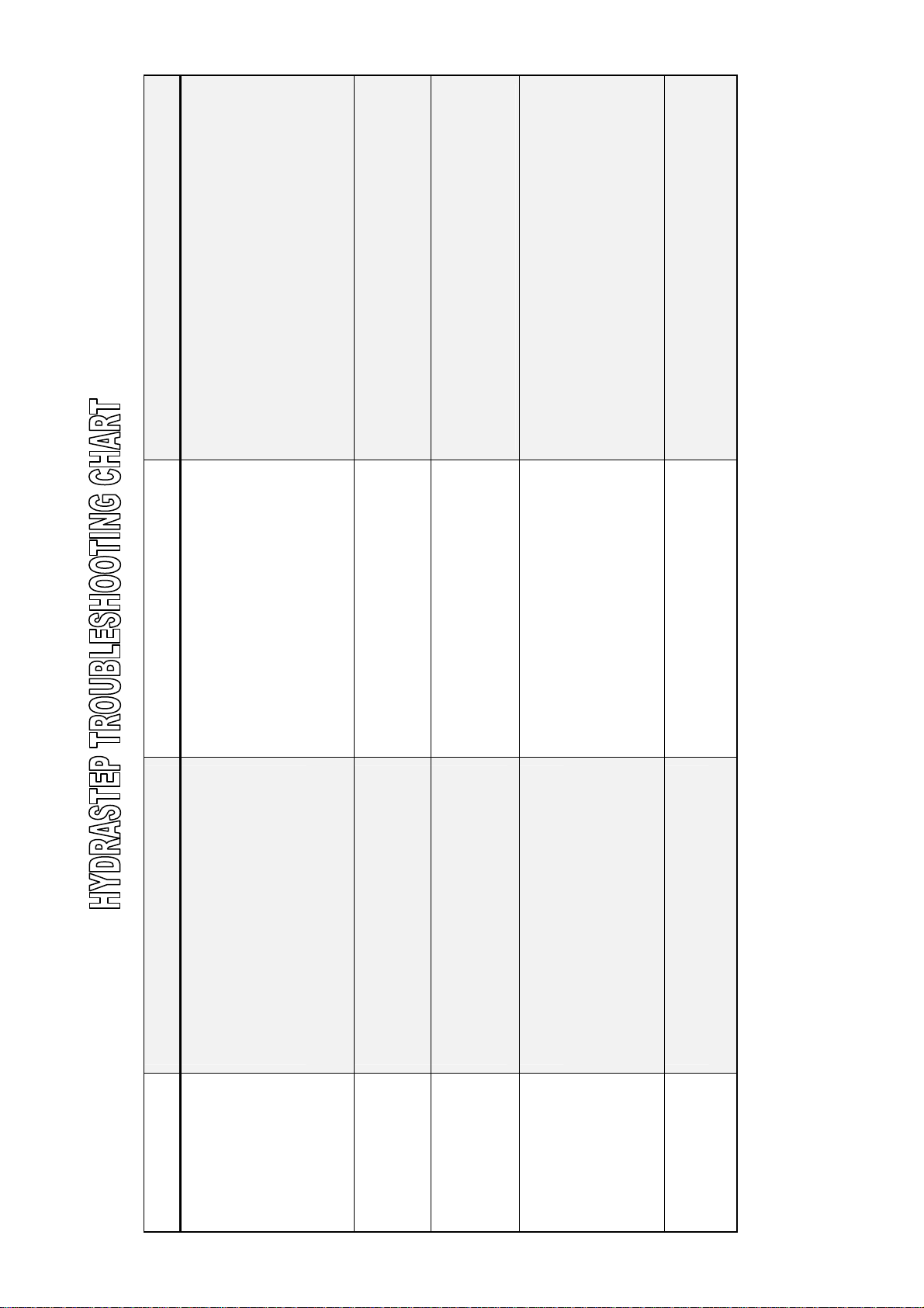
CATEGORY SYMPTOM POSSIBLE CAUSES (See Note 1) SOLUTION (See Note 2)
Hydrastep system does not power-up.
PSU (AC)
LED’s with Yellow alarm LED illuminated.
Hydrastep system does not power-up.
PSU (DC)
Chequered / intermittent display.
No display.
Yellow LED illuminated.
Chequered / intermittent display.
MAIN DISPLAY
REMOTE DISPLAY
No display.
Yellow LED illuminated.
Flashing Red (steam) and Green (water)
ERROR
ELECTRODE ALARM
yellow LED illuminated
Water above steam (green above red) with
SWITCHING
THRESHOLD
WATER/STEAM
Note 1: Further detailed information can be found in Fault finding Part 1, Sections 2.6 and 4.5.
Note 2: References are to Operating Manuals 24685033 (for 2468CA and 2468CC models) and 24685034 (for 2468CB and 2468CD models).
Page 3

condensate flow back into the column.
HYDRASTEP START-UP
It is possible that some of these conditions will be seen on a new Hydrastep installation.
** This does not mean that the equipment you have purchased is faul ty ** Due to the nature of the areas that Hydrastep is normally installed, various conditions can occur that make the instrument operate in an unusual manner.
It would be easy to think you have installed defective equipment, but it is very unlikely that this is the case.
Great care must be taken when installing a Hydrastep system so that these problems are less likely to be seen; firstly, please take th e time to ensure that the various people involved
in the fitting of the components have been shown and have read the handbook, which is supplied with all new Hydrastep systems.
This, along with the wiring diagrams (also supplied), should make for a trouble free installation. 1. Please read and understand Part 2 of the handbook, which explains the pressure sid e of the equ ipment.
2. Ensure wiring is of the correct type and that the wiring diagram supplied has been followed.
3. Hydrastep relies on a ‘path back to earth’. Please make sure that all earth points are made and are of a good standard.
4. Great care must be taken with the mounting of the water column; the columns must be vertical; angles stated in the manual should be as close as possible, as this ensures
5. Lagging of the pipe work must be as stated; ** The last 0.5 m of the (top) steam leg MUST NOT be insulated as this will inhibit condensate flow into the column; this will cause a
picked up on the electrodes and shows its self as a flickering in the bottom few electrodes. When the system is brought up to its normal working condition’s this will settle but
can take a couple of days to do so.
flickering display.**
water conductivity is high. We can modify the units up to 1600Us/cm.
include mains voltage to be used, trip points (if relay cards are to be fitted), number of electrodes to be used and remot e display option (if ordered). These points are not pre-set
as standard as the factory do not know your requirement unless stated on your order.
process and a new set should go in before you run the system up for the first time.
not a fault and is caused by a few conditions specific to power stations:
(a) If a boiler is new or has seen a large amount re-work, it may well get a coating of magnetite inside of it, when it is first started up. This creates a small DC voltage that is
6. Please be aware of your water quality as some adjustments to the Hydrastep may be required if it has a high conductivity. Please let us know when placing your order if your
7. Units will not leave the factory configured for customer orders unless requested. If you wish it to be configured, please request it on your order and it will then be done. Options
8. Care should be taken to make sure that a new set of electrodes have been fitted after the first acid wash of the system. The electrodes may well have been damaged during this
9. The most common problem seen with Hydrastep systems is a flickering pattern on the display while the boiler is being brought up to operating pressure and temperature. This is
) Should the plant generate a higher than normal amount of DC noise, we can supply a blocking cap that is built into a PCB that will stop this problem.
(b) It is possible that the top electrodes may have a wet coating on them until these working conditions are met; again, if left to settle, this will work at normal working conditions.
(c
If you are in any doubt about what you are doing, contact Customer Support of Mobrey Limited on +44 (0) 1753 756600 for guidance
Mobrey Customer Support
(April 2005)
Page 4
About this manual
This manual describes the Hydrastep 2468CB and 2468CD Electronic Gauging Systems along with the
recommended options. Except where stated otherwise, the information contained in this m anual can be assumed
to apply to either system.
This manual is divided into three parts; the first covers the electrical/electronic system; the second describes the
pressure parts; the third is for coverage of all other aspects.
Part 1 – Electrical/Electronic System
Chapter 1 introduces the Hydrastep 2468 Electronic Gauging System and its operating principles.
Chapter 2 covers the installation, configuration and fault analysis procedures.
Chapter 3 covers the installation, configuration and fault analysis procedures for the Relay Output Board (Chapter 3a),
the Delay Relay Output Board (Chapter 3b) and the Opto-isolated Output Board (Chapter 3c).
Chapter 4 covers the installation, configuration and fault analysis procedures for all versi ons of the Remote
Display Unit.
Part 2 – Pressure Parts
Chapter 1 is a general introduction to the Hydrastep system of water level determination.
Chapter 2 describes the water column and its components – the preparation, installation o f the water column on to
the boiler, acid and steam purging of the boiler system and the fitting of the electrode sensors.
Chapter 3 details the fault repair procedures carried out on the system pressure parts and their commissioning.
Chapter 4 provides a general description of the pressure parts used in the Hydrastep systems.
Chapter 5 details the Pressure Parts specifications.
Caution:
For installation under the Pressure Equipment Directive (PED) 97/23/EC, refer to safety instruction
manual 24688006/SI.
Caution:
For installation under ATEX directive 94/09/EC, refer to safety instruction manual 24685033/SI.
Part 3 – Appendix
Appendix A contains a CSA certified connection drawing and associated notes.
Caution:
For installation in potentially explosive atmospheres in Canada and USA, refer to control drawing
24685037 in Part 3.
Page 5
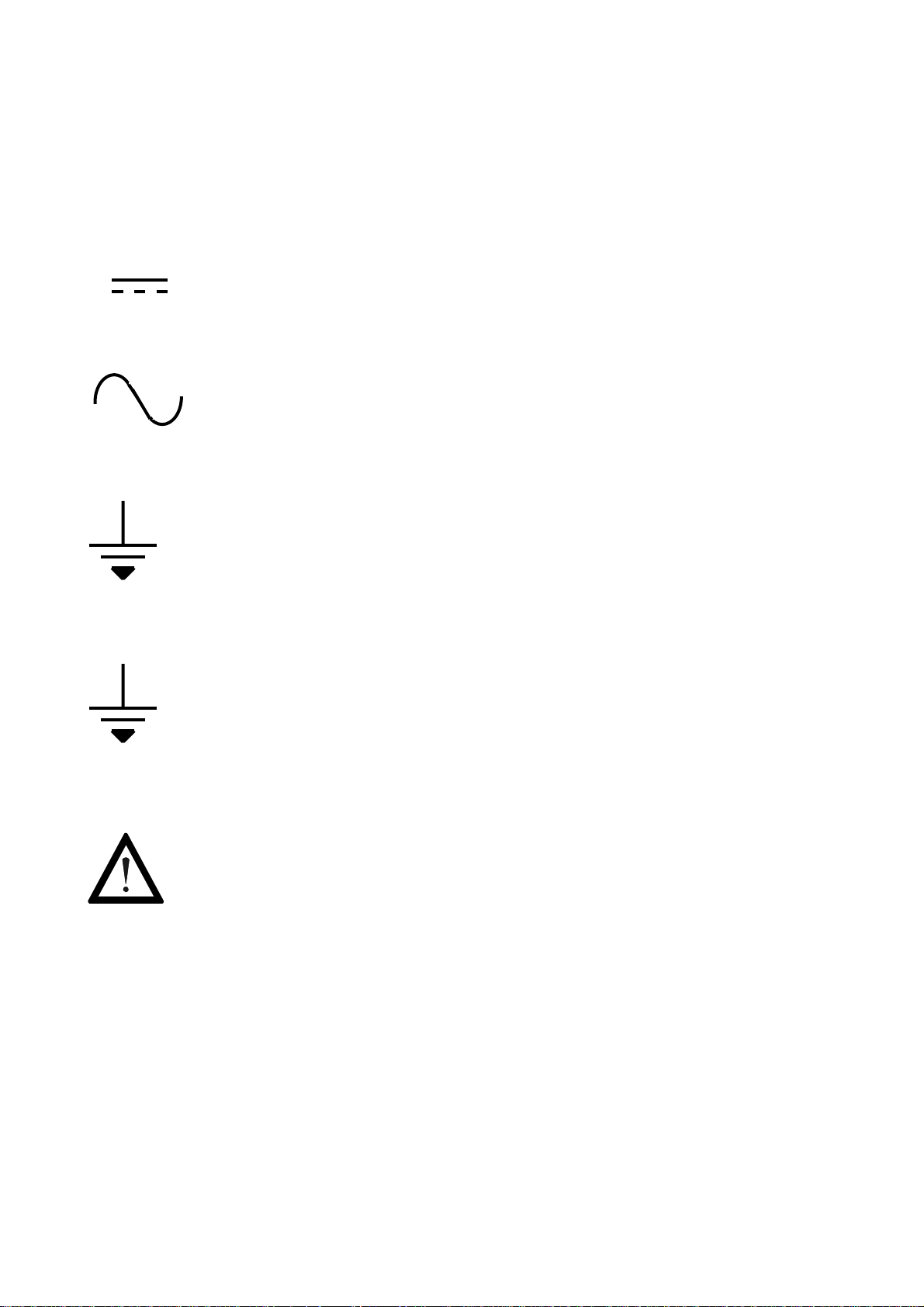
SYMBOLS USED IN THIS MANUAL AND ON THE UNIT
Symbol Meaning
Direct Current
Alternating Current
Earth (ground) terminal
Protective conductor terminal
Caution (refer to accompanying documents)
Page 6

Page 7

Part 1
Hydrastep 2468CB & 2468CD
Electronic Gauging System
24685034 Pt.1-1
Page 8

Pt.1-2 24685034
Page 9

DANGEROUS VOLTAGES ARE PRESENT IN
THIS EQUIPMENT. ANY WARNING NOTICES
OR PROCEDURES CONTAINED IN THIS
MANUAL OR ON THE EQUIPMENT SHOULD BE
STRICTLY OBSERVED TO MAINTAIN SAFETY.
THE USE OF THIS EQUIPMENT IN A MANNER
NOT SPECIFIED IN THIS MANUAL MAY IMPAIR
THE PROTECTION PROVIDED BY THIS
EQUIPMENT. GREAT CARE SHOULD BE
EXERCISED WHEN SERVICING THIS
EQUIPMENT.
TO ENSURE COMPLIANCE WITH THE EMC
DIRECTIVE (WHERE APPLICABLE) THE
INSTRUCTIONS ON CABLE SCREENING,
ROUTING AND TERMINATION GIVEN IN THIS
MANUAL MUST BE FOLLOWED.
24685034 Pt.1-3
Page 10

Pt.1-4 24685034
Page 11

Part 1
Contents
Chapter 1 Introduction to the Hydrastep 2468 Electronic
Gauging System
Chapter 2 2468CB & 2468CD Dual Power Supply Version
Chapter 3a 2468 - Relay Output Board Option
Chapter 3b Delay Relay Output Board Option
Chapter 3c 2468 Opto-isolated Output Board Option
Chapter 4 Remote Display Options 24683B C & D
24685034 Pt.1-5
Page 12

Pt.1-6 24685034
Page 13

Hydrastep 2468CB and 2468CD Manual Introduction to the Hydrastep 2468 Electronic Gauging System
1
Introduction to the Hydrastep 2468
Electronic Gauging System
Contents
Page No.
1.1 WATER LEVEL MEASUREMENT .......................................................... 3
1.2 HYDRASTEP 2468 ELECTRONIC GAUGING SYSTEM ....................... 5
1.2.1 INPUT BOARDS .................................................................................. 5
1.2.2 DISPLAY BOARDS .............................................................................. 5
1.2.3 SYSTEM FAULTS (2468CB OR 2468CD) ........................................... 6
24685034
1.3 SYSTEM OPTIONS ................................................................................. 6
1.3.1 OUTPUT BOARDS .............................................................................. 6
1.3.2 REMOTE DISPLAY UNITS .................................................................. 6
1.3.3 OPTION DETAILS ................................................................................ 6
1.4 HYDRASTEP 2468 UPGRADE PATHS AND AVAILABLE OPTIONS .. 7
Illustrations
Figure 1.1 - Front panel of the Hydrastep 2468 gauging system, with local display .......... 2
Figure 1.2 - Schematic of resistance measuring cell and electrodes ................................. 3
Figure 1.3 - Typical Hydrastep 2468 System Installation.................................................... 4
Tables
Table 1.1 - Upgrade paths and available options ............................................................... 7
1-1
Page 14
Introduction to the Hydrastep 2468 Electronic Gauging System Hydrastep 2468CB and 2468CD Manual
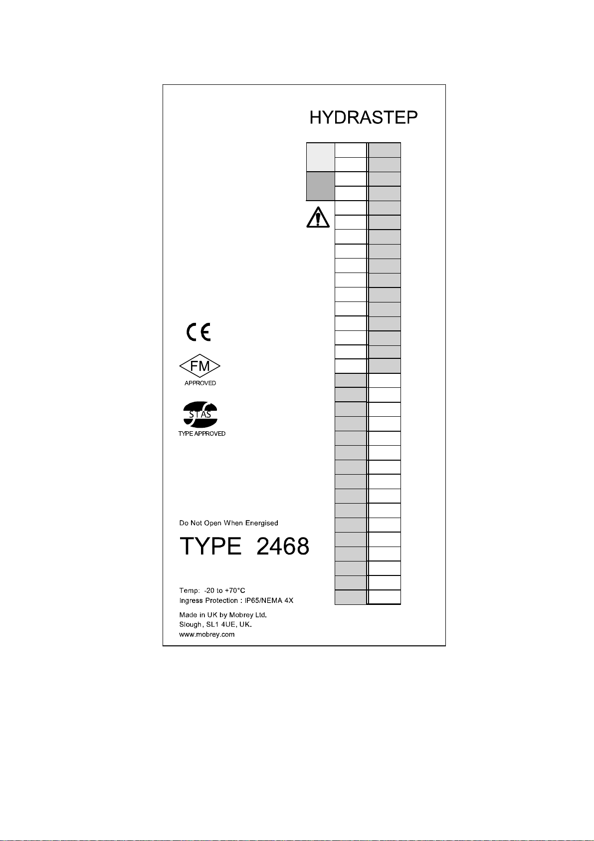
0040
Figure 1.1 - Front panel of the Hydrastep 2468 gauging system
1-2 24685034
Page 15
Hydrastep 2468CB and 2468CD Manual Introduction to the Hydrastep 2468 Electronic Gauging System
1.1 WATER LEVEL MEASUREMENT
The Hydrastep 2468 Electronic Gauging System is designed as an electronic alternative to
water level gauges on boilers, giving a more reliable and safer water level indication than
conventional visual gauges. It uses the significant difference in resistivities of water and
steam in temperatures up to 370C (698F) to determine the water level.
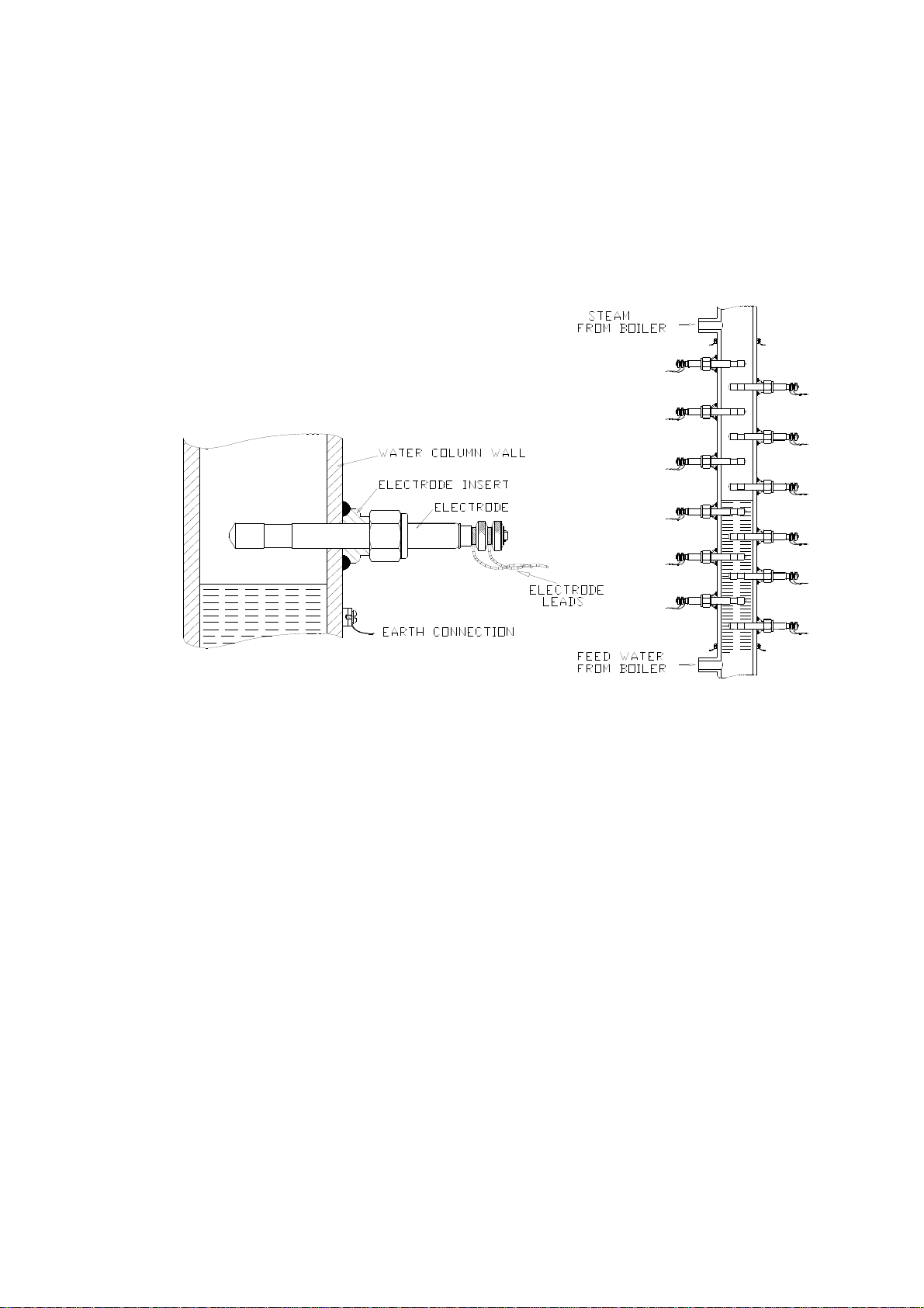
Figure 1.2 - Schematic of resistance measuring cell and electrodes
A vertical row of electrodes is installed in the water level column attached to boiler and
typically aligned so that half the electrodes are above and half below the normal water level
(see Figure 1.2). The resistance measurement is made between the insulated tip of each
electrode and the wall of the column.
The “cell constant” defining the actual resistance measured is determined by the length and
diameter of the electrode tip and the column bore. In practice, the cell constant is chosen so
that the resistance in water is less than 100k ohms and the steam resistance is greater than
10M ohms. Since the resistivities of water and steam are substantially different, the system
is simple and requires no setting up adjustments. It is not susceptible to power supply
variations, ambient temperature changes, etc., resulting in a highly reliable system.
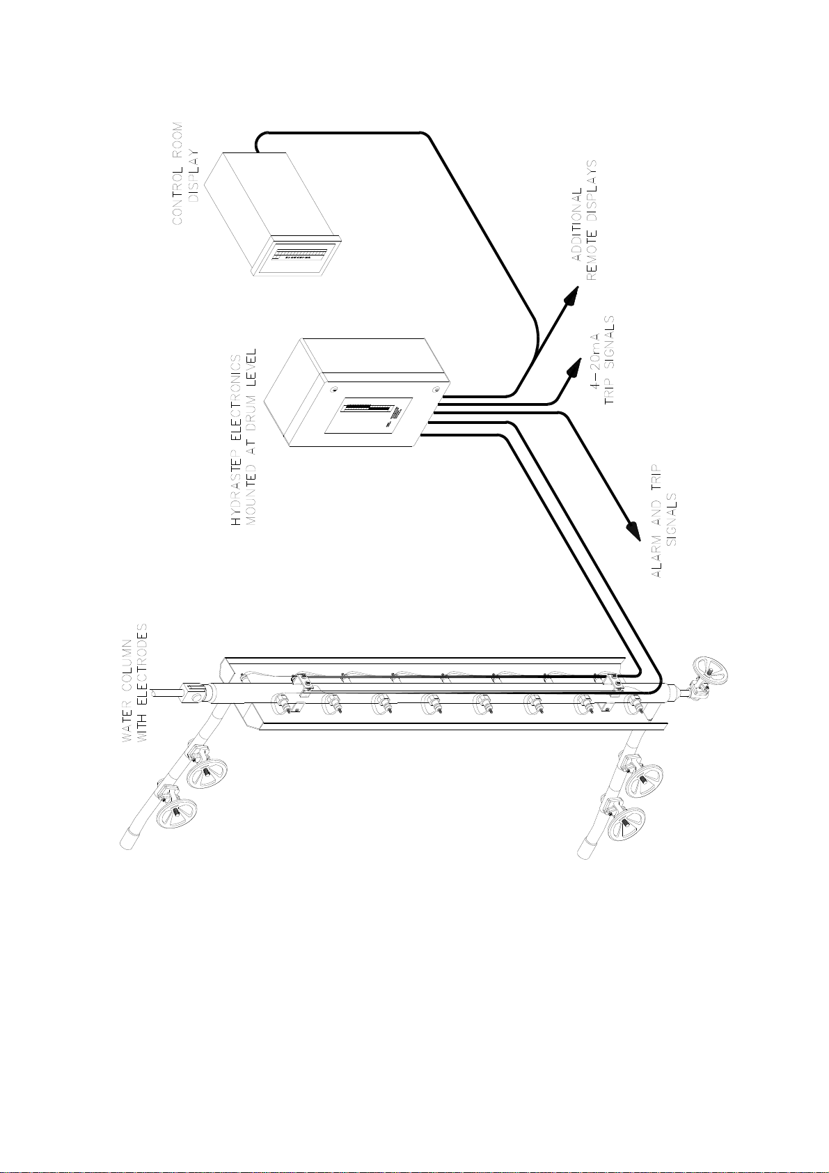
A general overview showing how a typical Hydrastep 2468 System is installed is illustrated
in Figure 1.3.
24685034
1-3
Page 16
Introduction to the Hydrastep 2468 Electronic Gauging System Hydrastep 2468CB and 2468CD Manual
Figure 1.3 - Typical Hydrastep 2468 System Installation
1-4 24685034
Page 17

Hydrastep 2468CB and 2468CD Manual Introduction to the Hydrastep 2468 Electronic Gauging System
1.2 HYDRASTEP 2468 ELECTRONIC GAUGING SYSTEM
The Hydrastep 2468 is a sophisticated and flexible electronic gauging system. It is supplied
in two main versions:
A Single Power Supply System with Local Level Display
A Dual Power Supply System with Local Level Display
For both systems, the printed circuit boards are housed in the same enclosure, al lowing
customers full capability to expand their system as and when conditions dictate.
Table 1.1 on page 1.7 is a summary of all upgrade paths and options for the Hydrastep 2468
system.
1.2.1 INPUT BOARDS
All versions of the Hydrastep 2468 unit contain one or two input boards. The input boards
mount on to the base plate in the enclosure. Each input board provides power supplies,
electrode drive, signal processing, fault analysis and an analogue output.
The input board can accept inputs from 8, 10, 12, 14 or 16 electrodes. When two input
boards are used (in a ‘dual power supply’ system) the electrodes are ‘interlaced’; that is, the
odd numbered electrodes are connected to one input board and the even numb ered
electrodes are connected to the other. Full details of the wiring are covered in Chapter 2
under Installation.
Each input board also includes a current output circuit that provides an analogue
representation of the water level in the column. The analogue output can be configured to
give a current output in one of the following ranges:
0 to 20mA
4 to 20mA
20 to 0mA
20 to 4mA
1.2.2 DISPLAY BOARD
The display board is mounted on to the hinged lid of the unit and provides indication through
the viewing window on the enclosure. It also supplies configuration information to the input
board(s); that is, the number of electrodes connected to the unit and the required
water/steam switching threshold.
Figure 1.1 shows the local display with water level and system fault indication. Water level
is indicated by two columns of LEDs, one red to indicate steam and one green to indicate
water. The number of LEDs illuminated is dependent on the number of electrodes present
and a blanking panel is available to mask the LEDs not used. In addition to the system fault
indication is an opto-isolated system fault output. Switches are provided to allow the
number of electrodes to be selected (8, 10, 12, 14, 16, 18, 20, 22, 24, 26, 28, 30 or 32). Two
solder link pads are provided to select the water/steam switching threshold (0.6S/cm or
1.6S/cm).
24685034
1-5
Page 18

Introduction to the Hydrastep 2468 Electronic Gauging System Hydrastep 2468CB and 2468CD Manual
1.2.3 SYSTEM FAULTS (2468CB OR 2468CD)
System fault indication, a yellow LED and an opto-isolated output, is provided for a ‘water
above steam’ condition, an electrode fault or wiring failure and the detection of an internal
fault. A further fault is indicated when the electrode number switch is incorrectly set. This
fault is indicated by a chequered display of red and green LEDs on the level display.
Faults and their remedies are covered in Chapter 2 under ‘Fault Analysis & Corrective
Action’.
1.3 SYSTEM OPTIONS
1.3.1 OUTPUT BOARDS
Each input board can accept one or two output boards that can be used for water level
signalling, alarm or trip functions. Each output board provides four relay outputs or four optoisolated outputs. The first output board is fitted directly on top of the input board using three
nylon pillars. A second output board (when required) can be fitted on top of the first output
board using the same type of fixture. The various output boards are described in Chapter 3.
1.3.2 REMOTE DISPLAY UNITS
Provision is made to drive Remote Display Units. The display board is capable of driving up
to 6 remote display units. Only one of these can be powered by the Hydrastep unit, any
additional remote displays must be locally powered.
A remote display unit ‘mimics’ the display on the Hydrastep 2468 and is as described in
Chapter 4.
1.3.3 OPTION DETAILS
1. Relay Board 24680504 has 4 fully configurable relay outputs Chapter 3a
2. Relay with Time Delay board 24680509 has 4 fully configurable relay outputs Chapter 3b
3. Opto-isolator board 24680505 has 4 full y configurable opto-isolated outputs Chapter 3c
4. Remote Display 24683B. Panel mounted DIN size 8 to 32 electrode display Chapter 4
5. Remote Display 24683C Panel mounted large LED 8 to 32 ele ctrod e display Chapter 4
6. Remote Display 24683D Wall mounted splash proof version of 24683C Chapter 4
1-6 24685034
Page 19
Hydrastep 2468CB and 2468CD Manual Introduction to the Hydrastep 2468 Electronic Gauging System
1.4 HYDRASTEP 2468 UPGRADE PATHS AND AVAILABLE
OPTIONS
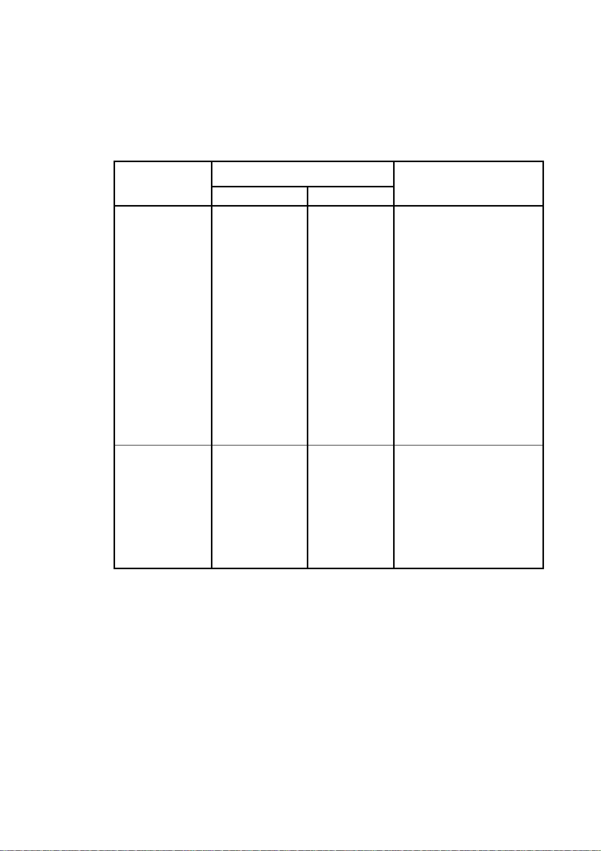
Table 1.1 describes the available versions of the Hydrastep 2468 Electronic Gauging System
and their possible options.
Existing System
2468 CA or
2468 CC
16 point EGS with
local display
Single power
supply.
2468 CB or
2468 CD
32 point EGS with
local display
Dual power supply.
Available Options
Description Part No.
Relay output board
Time delay relay
output board
Opto-isolated
output board
Remote display
unit
Input board
upgrade (ac)
Input board
upgrade (dc)
Relay output board
Time delay relay
output board
Opto-isolated
output board
Remote display
unit
24680504C
24680509B
24680505A
24683B, C, or D
24680501C
24680516B
24680504C
24680509B
24680505A
24683B, C, or D
Comments
}
}
} Up to two boards (of any one
} type) can be fitted.
}
}
Up to 6 can be used
Provides an additional power
supply (ac mains source) and
16 point input circuit. Upgrades
2468CA to 2468CB.
Provides an additional power
supply (24V dc source) and 16
point input circuit. Upgrades
2468CC to 2468CD.
}
}
} Up to four boards (of any one
} type) can be fitted.
}
}
Up to 6 can be used
24685034
Note: If required, a 24680501C board can be fitted to a 2468CC (or a 24680516B board
can be fitted to a 2468CA) to upgrade to a 2468CE. The 2468CE is a 32 point
Electronic Gauging System (EGS) with one ac mains source power supply and one
24Vdc source power supply.
Table 1.1 - Upgrade paths and available options
1-7
Page 20

Introduction to the Hydrastep 2468 Electronic Gauging System Hydrastep 2468CB and 2468CD Manual
1-8 24685034
Page 21

Hydrastep 2468CB and 2468CD Manual 2468CB & 2468CD Dual Power Supply Version
2
2468CB & 2468CD
Dual Power Supply Version
Contents
Page No.
2.1 INTRODUCTION ....................................................................................... 2-3
2.2 ELECTRODE CABLING SYSTEM ........................................................... 2-3
2.3 ELECTRONIC ENCLOSURE .................................................................... 2-3
2.3.1 INPUT BOARD (PCB 24680501 AND PCB 24680516) ......................... 2-5
2.3.1.1 Analogue Output Drive Capability ........................................... 2-5
2.3.2 REMOTE DISPLAY DRIVE CAPABILITY .............................................. 2-5
2.3.3 DISPLAY BOARD (PCB 24680515)....................................................... 2-6
2.3.3.1 Link LK1 .................................................................................. 2-6
2.3.3.2 Links LK2, LK3, LK4 and LK5 ................................................. 2-7
2.3.4 PCB INTERCONNECTIONS .................................................................. 2-7
2.4 INSTALLATION ........................................................................................ 2-8
2.4.1 MECHANICAL INSTALLATION ............................................................. 2-8
2.4.2 ELECTRICAL INSTALLATION ............................................................. 2-10
2.4.2.1 Electrode Connections .......................................................... 2-10
2.4.2.2 Connecting Cables to Water Column Electrodes ................. 2-11
2.4.2.3 Connecting the Electrode Cable Assemblies to 2468
Enclosure………………………………………………………....2-12
2.4.2.4 Hydrastep Power Supply Cables .......................................... 2-13
2.4.2.5 Analogue Output Connection ................................................ 2-15
2.4.2.6 Opto-Isolated Fault Output Connection ................................ 2-16
2.5 SYSTEM CONFIGURATION .................................................................. 2-17
2.5.1 INPUT BOARD (PCB 24680501 OR 24680516) ................................. 2-17
2.5.1.1 Analogue Output Configuration ............................................. 2-17
2.5.1.2 Pulsed Output Setting ........................................................... 2-18
2.5.1.3 Electrode Error Configuration ............................................... 2-18
2.5.1.4 Configuring the Unit to Detect Electrode Error ..................... 2-19
24685034
2-1
Page 22

2468CB & 2468CD Dual Power Supply Version Hydrastep 2468CB and 2468CD Manual
2.5.2 DISPLAY BOARD 24680515 ............................................................... 2-20
2.5.2.1 Link LK1 Setting .................................................................... 2-20
2.5.2.2 Configuring the ‘Number of Electrodes’ Switch .................... 2-20
2.5.2.3 ‘Switching Threshold’ Setting ................................................ 2-22
2.5.2.4 ‘Compatibility’ Setting ............................................................ 2-22
2.6 FAULT ANALYSIS & CORRECTIVE ACTION ....................................... 2-23
2.6.1 COMPONENT REPLACEMENT .......................................................... 2-30
2.6.1.1 Removing the Input Board (24680501 or 24680516) ........... 2-30
2.6.1.2 Refitting the Input Board ....................................................... 2-30
2.6.1.3 Removing the Display Board 24680515 ............................... 2-30
2.6.1.4 Refitting the Display Board ................................................... 2-30
2.6.2 PARTS LIST - HYDRASTEP 2468 CB & CD VERSIONS ................... 2-31
2.7 SPECIFICATION ..................................................................................... 2-32
Illustrations
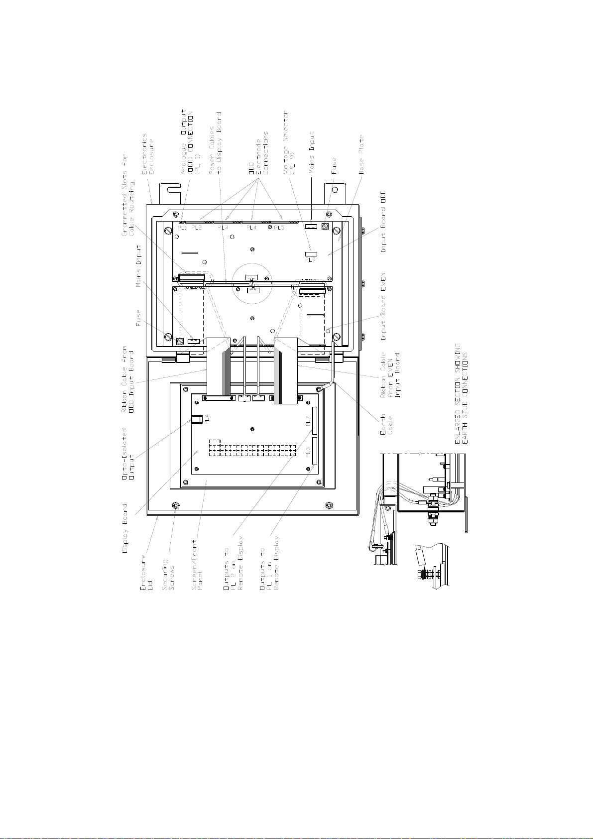
Figure 2.1: Outline drawing showing PCB layout and interconnections ............................... 2-4
Figure 2.2: Installation diagram for Hydrastep 2468 Electronic Gauging System unit ......... 2-9
Figure 2.3: Enclosure cable layout for 16 electrode system ............................................... 2-12
Figure 2.4: Voltage Selection (240V or 110V) .................................................................... 2-14
Figure 2.5- Location of display board links LK1 to LK5 & switch SW1 with configuration…..….
details………………………………………………………………………………….2-21
Figure 2.6- Split pads SP1, SP2, SP5 & SP6 locations and settings ................................. 2-22
Tables
Table 2.1 - Analogue output configurations ...................................................................... 2-17
Table 2.2 - Number of electrodes being displayed ........................................................... 2-20
Table 2.3 - Fault analysis/corrective action chart ............................................................. 2-23
2-2 24685034
Page 23
Hydrastep 2468CB and 2468CD Manual 2468CB & 2468CD Dual Power Supply Version
2.1 INTRODUCTION
This chapter introduces the dual power supply version of the Hydrastep 2468 Ele ctronic
Gauging System, its mechanical installation, system configuration, simple fault
analysis/corrective action capability and its specification.
2.2 ELECTRODE CABLING SYSTEM
This system can have 8, 10, 12, 14, 16, 18, 20, 22, 24, 26, 28, 30 or 32 electrodes and uses
18-core electrode cables. The cables consist of nine pairs of coloured cores with the black
cores in each cable used for the EARTH terminations. Each electrode requires one pair of
cores, one core for the signal drive and one for the signal return.
Number of
Electrodes
8
10-16
18-24
26-32
The electrode cable is pre-formed for simple installation. The connections to the electrodes
are terminated on the connection stud of the electrode. Either core can be connected to the
electronic enclosure as the signal drive or return.
Number of Cables
2.3 ELECTRONIC ENCLOSURE
The basic arrangement of boards in the electronic enclosure is as follows:
Two input board s su pply power to the system and to the input signal processing
circuits. These boards are: PCB 24680501, ac (mains) input, or PCB 24680516, dc
input. One board is mounted on the right hand side of the base plate and receives the
odd numbered electrode inputs. The other board is mounted on the left hand side of
the base plate and receives the even numbered electrode inputs.
A display board (PCB 2468 0515) contains the LED drive circuits for the two columns
(32 red LEDs and 32 green LEDs) and the system fault LEDs. This board is mounted
on the rear of the front panel, with the LEDs protruding through the front panel.
Required
1
2
3 or 4
4
Up to four output boards, Relay Board (P CB 24680504), Relay with time delay Board
(24680509) or Opto-isolator Board (PCB 24680505) may be fitted, two per input
board. Output board mounting pillars are fitted to each input board during
manufacture to support the first output board mounted.
Refer to Figure 2.1 on page 2-4 for an annotated view of the internal layout of the unit.
24685034 2-3
Page 24
2468CB & 2468CD Dual Power Supply Version Hydrastep 2468CB and 2468CD Manual
Figure 2.1: Outline drawing showing PCB layout and interconnections
2-4 24685034
Page 25

Hydrastep 2468CB and 2468CD Manual 2468CB & 2468CD Dual Power Supply Version
2.3.1 INPUT BOARD (PCB 24680501 AND PCB 24680516)
The input board processes the electrode inputs to provide water level data for display
purposes and a current output representing the water level. Fault detection is also carried
out where the condition of the electrode inputs are examined and a FAULT is indicated
when:
1. An open circuit in either of the electrode conductor cores is present.
2. A short circuit to EARTH on either the electrode or conductor cores.
3. A water above steam condition exists.
4. An internal circuit fault condition exists.
A current output circuit is also provided on each input board. This gives an analogue
representation of the water level. The sense (forward or reverse) and type (0-20mA or
4-20mA) is selectable and described in Section 2.5 of this chapter. Fault indication on the
analogue output is an oscillating waveform (of approximately 0.5 Hz) superimposed on the
main analogue signal.
The electrode inputs to each input board are passed to the other input board so that each
analogue circuit can output the full range content of electrode input signals. However,
should either of the input boards fail, the remaining board recognises that data is missing
and doubles its own electrode input signal to remedy the data loss giving a maximum error of
± 1 electrode.
Provision is made on each input board to accept one or two output boards, either relay
outputs or opto-isolated outputs. Both types of output board are offered as options.
Each input board produces the power supplies for the whole instrument which are derived
either from the local mains voltage supply of 110V ac or 240V ac nominal for the 24680501
input board or 20V dc to 40V dc for the 24680516 input board.
Apart from the input voltage there are two other differences between the AC (24680501) and
DC (24680516) input boards. These are the analogue output drive capability and the
remote display drive capability.
2.3.1.1 Analogue Output Drive Capability
With the minimum DC supply voltage of 20V for the DC input board (24680516) the
maximum load that can be driven by the analogue output is 500.
At the minimum mains input voltage the AC input board (24680501) the maximum load that
can be driven by the analogue output is 600.
2.3.2 REMOTE DISPLAY DRIVE CAPABILITY
The remote display drive capability is only a consideration when the 2468C is providing
power for a remote display. With either input board the unit is capable of driving six remote
displays at up to 1000m (3280ft) from the unit but only powering one remote display (any
others must be locally powered). With the AC input board the maximum cable loop
resistance to the remote display is 27 whilst with the DC in put the maximum cable loop
resistance to the remote display is 7. (See remote display section for more details).
24685034 2-5
Page 26

2468CB & 2468CD Dual Power Supply Version Hydrastep 2468CB and 2468CD Manual
2.3.3 DISPLAY BOARD (PCB 24680515)
The display board receives its power supplies and electrode data from the input boards.
This data is decoded and used to illuminate the required LEDs mounted on the display
board. The data is also converted to serial format for transmission to remote display units.
The water level in the column is indicated on the front panel by two columns of 32 LEDs, one
green column to indicate the electrodes which are in water and one red column to indicate
the electrodes which are in steam. The number of LEDs illuminated is dependent on the
number of electrodes being used in the system. When 8 to 16 electrodes are being used,
the unit illuminates two LEDs per electrode. When between 18 and 32 electrodes are being
used, the unit illuminates one LED per electrode. In both cases, the display is top biased
(unused LEDs are at the bottom of the display). A blanking label is provided to mask any
LEDs that are not used.
The system fault is indicated by the yellow LED. Provision is also made for external
indication of a system fault. This takes the form of an opto-isolated output which is normally
in its short-circuit state. When an alarm condition exists, the opto-isolated output is opencircuited.
Full illumination of the Fault LED indicates a water above steam condition has been
detected. Illumination of half the Fault LED indicates an electrode, wiring or input board
related fault. The top half of the Fault LED illuminates when faults are detected by the left
hand input board (the even electrodes) and the bottom half of the Fault LED illuminates
when faults are detected by the right hand input board (the odd electrodes). Faults are
covered under “Fault Analysis & Corrective Action” in section 2.4 of this chapter.
The switch that sets the number of electrodes to be scanned is also mounted on this board.
A ‘chequered pattern’ is displayed by the RED and GREEN columns if an invalid switch
setting is made on the number of electrodes switch.
The water/steam switching threshold (0.6S/cm or 1.6S/cm) may be changed by solder
split pads.
2.3.3.1 Link LK1
The display board caters for both single input board and dual input boards versions of the
Hydrastep 2468 system. With dual input boards, the odd electrode inputs are connected to
one half of the display board circuit with the even electrode inputs connected to the other half
of the circuit.
With the single input board, only one half of the board is connected to the odd and even
electrode inputs. In this case the link LK1 must be fitted to connect the odd and even
halves of the display board circuit.
Note: This link MUST be removed for the dual input board system.
2-6 24685034
Page 27

Hydrastep 2468CB and 2468CD Manual 2468CB & 2468CD Dual Power Supply Version
2.3.3.2 Links LK2, LK3, LK4 and LK5
These links are used to select either the 8 - 16 display mode (two LEDs per electrode) or the
18 - 32 display mode (one LED per electrode).
Two link headers are provided with the unit and must be fitted in either LK2 and LK4, to
enable the 8 - 16 electrode mode, or LK3 and LK5, to enable the 18 - 32 electrode mode.
No. of Electrodes used Link Headers fitted
8 - 16 electrodes LK 2 & LK 4
18 - 32 electrodes LK 3 & LK 5
See also Figure 2.5 on page 2-21.
2.3.4 PCB INTERCONNECTIONS
Signal interconnection between the input boards and the display board is via ribbon cables.
The power supplies to the display board come from each input board via a 6-core cable.
Slots are provided in the base plate to guide the cables towards the hinge-side of the
enclosure case, thus minimising any cable strain when the enclosure lid is o pened. See
Figure 2.1 for layout details.
24685034 2-7
Page 28

2468CB & 2468CD Dual Power Supply Version Hydrastep 2468CB and 2468CD Manual
2.4 INSTALLATION
This section deals with the mechanical installation of the electronic enclosure and the
electrical connections required for the basic system. Any installation dealing with the options
available for use on this version of the system are covered in Chapters 3 & 4.
Notes:
1. The Electronic Enclosure cover should not be remove d or opened until the equipment is
ready for physical installation to its fixing point. Under no circumstances should the
Electronic Enclosure be left open unless internal work is actually in progress.
2. When working on a bench with the enclosure open, the lid should be supported in its
open position.
3. To clean the instrument, use a damp cloth with a mild, water-based cleaner. Cl ean the
exterior of the instrument only. Do not allow liquids to enter or spill into the instrument.
2.4.1 MECHANICAL INSTALLATION
The electronic enclosure must be sited within electrode cable length of the water column fixture.
The preferred site for the electronic enclosure is a wall or vertical bracket structure where easy
access is available for viewing and servicing, and of suitable composition/load bearing ability to
be capable of supporting 4 times the equipment weight (see page 2-32 for weight specification.)
It is assumed that the water column is fully installed.
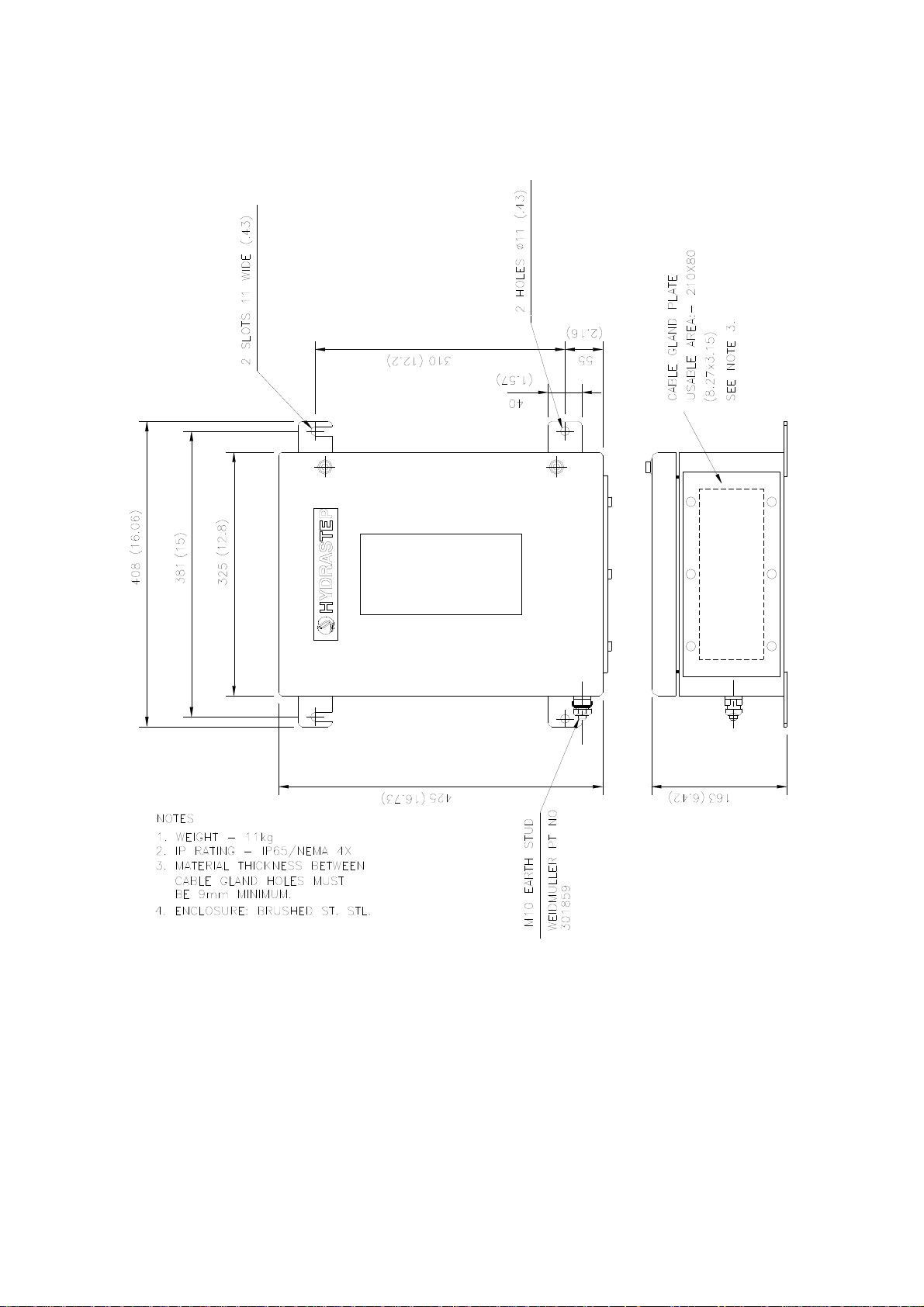
The electronic enclosure is equipped with four welded feet, allowing it to be secured in a
vertical position. Using a template derived from the enclosure details, given in Figure 2.2,
drill the necessary holes in the prepared surface. Secure the electronic enclosure with M10
bolts or equivalent fixings.
The wiring enters the unit through a gland plate in the bottom of the enclosure. A blank
gland plate is provided to give users a choice in the type of glands and gland configuration
for the required system. Alternatively, cable entry can be made directly via trunking. Note
that the gland plate should be removed for fitting of the glands. EMC compatibility for
European installations is proven for an enclosure using a gland plate and RF glands making
a good annular (ring shape) connection to screened cables for all connection s. An
installation using unscreened cables or trunked routing without a gland plate and RF gland
would not be covered by the manufacturer’s EMC declaration of conformity.
The cabling involved is:
Mains Supplies (2 cables) Remote Display (up to 6 cables)
Electrode Inputs (up to 4 cables) Analogue Outputs (1 or 2 cables)
Relay or Opto-isolated Outputs Opto-isolated Fault Output (1 cable)
(Up to 16 relay or opto-isolated outputs)
2-8 24685034
Page 29
Hydrastep 2468CB and 2468CD Manual 2468CB & 2468CD Dual Power Supply Version
Figure 2.2: Installation diagram for Hydrastep 2468 Electronic Gauging System unit
24685034 2-9
Page 30
2468CB & 2468CD Dual Power Supply Version Hydrastep 2468CB and 2468CD Manual
2.4.2 ELECTRICAL INSTALLATION
This section deals with the interconnection between the electrodes and the electronic
enclosure, the connection of the ac mains power supply to the electronic en closure and the
analogue output connections from the electronic enclosure.
2.4.2.1 Electrode Connections
Hydrastep Electrode Cables
Special electrode cable assemblies of length 3, 10, 18 or 30 metres are provided with the
system for connecting the Hydrastep 2468 Electronic Enclosure to the Water Column
Electrodes. The cable looms are 18-core multi-strand conductors.
The conductors are colour coded for ease of installation and have pure nickel ring clamps
fitted at one end for connection to the electrodes. A set of wire crimps is provided for use on
the Enclosure connections.
The black conductors in each cable are used for the EARTH terminations, leaving eight
pairs of coloured conductors for connection to the electrodes. At least one cable assembly is
required and certain conductor pairs in the cables will be redundant. The exceptions are the
8, 16 and 32 electrode systems where all the conductors in the cables are fully used.
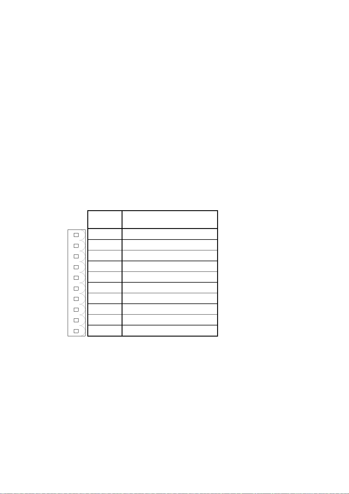
Electrode connections
Pin
Number
1
2
3
4
5
6
7
8
9
10
Function PL2, PL3, PL4, PL5
Electrode Drive
Electrode Pickup
Functional Earth
Electrode Drive
Electrode Pickup
Electrode Drive
Electrode Pickup
Functional Earth
Electrode Drive
Electrode Pickup
The connection requirements for
the 16 electrode system is used as
the example case. A full set of
electrode connection diagrams is
included at the end of Chapter 2
covering the pin-by-pin pairings for
all electrode systems mentioned.
2-10 24685034
Page 31

Hydrastep 2468CB and 2468CD Manual 2468CB & 2468CD Dual Power Supply Version
2.4.2.2 Connecting Cables to Water Column Electrodes
(16 Electrode System - See Page 2-WD.7)
The following assumes that the electrodes have been fitted to the water column.
1. Gain access to the electrodes mounted on the water column.
2. Undo both knurled nuts on the stud of the bottom electrode (referenced EL.1 on the
drawings) and remove both the nuts and washers.
3. Take one of the brown (BN) conductors in Cable 1 and fit the ring clamp of the
conductor over the stud, followed by a washer and a knurled nut. Tighten the nut to form
a good secure contact, ensuring the conductor run to the cableform clamping bar is free
from snags and sharp bends.
4. Repeat the operation for the remaining brown (BN) conductor of Cable 1.
5. Take the next electrode up, referenced EL.2 on the drawings, and repeat the operations
detailed in paragraph 2 above.
6. Take the brown (BN) conductors of Cable 2 and repeat the fitting instructions d etailed in
paragraph 3 above.
7. Repeat the operations of paragraphs 2 and 3 for the remaining tabulated
conductor/electrode pairings on the next page and connect as detailed on page 2-WD.7.
8. Check that all conductor runs affecting Cables 1 and 2 on the water colu mn are
satisfactory then clamp the cable securely to its clamping bar.
9. Refit any Electrode Protection Covers to the water column.
Water column connections for 16 electrodes
Electrode
Number
1 Brown 1 PL2 pin 1 10 Green 2 PL3 pin 1
Brown PL2 pin 2 Green PL3 pin 2
2 Brown 2 PL2 pin 1 11 Blue 1 PL3 pin 4
Brown PL2 pin 2 Blue PL3 pin 5
3 Red 1 PL2 pin 4 12 Blue 2 PL3 pin 4
Red PL2 pin 5 Blue PL3 pin 5
4 Red 2 PL2 pin 4 13 Purple 1 PL3 pin 6
Red PL2 pin 5 Purple PL3 pin 7
5 Orange 1 PL2 pin 6 14 Purple 2 PL3 pin 6
Orange PL2 pin 7 Purple PL3 pin 7
6 Orange 2 PL2 pin 6 15 Grey 1 PL3 pin 9
Orange PL2 pin 7 Grey PL3 pin 10
7 Yellow 1 PL2 pin 9 16 Grey 2 PL3 pin 9
Yellow PL2 pin 10 Grey PL3 pin 10
8 Yellow 2 PL2 pin 9 Earth Black 1 PL2 pin 3
Yellow PL2 pin 10 Black PL2 pin 3
9 Green 1 PL2 pin 9 Earth Black 2 PL2 pin 3
Green PL2 pin 10 Black PL2 pin 3
Conductor
Number
Cable
Number
Enclosure
Connection
Electrode
Number
Conductor
Number
Cable
Number
Enclosure
Connection
Note: There are two conductors of each colour per cable.
24685034 2-11
Page 32

2468CB & 2468CD Dual Power Supply Version Hydrastep 2468CB and 2468CD Manual
Figure 2.3: Enclosure cable layout for 16 electrode system
2.4.2.3 Connecting the Electrode Cable Assemblies to 2468 Enclosure
WARNING Mains voltages are present in this instrument when power
is connected. De-energise before opening front cover.
Four 10-way plugs are provided on each PCB1 to terminate all the necessary connections
from the electrode cables.
1. Ensure power is removed from electroni c en closure and open the front cover.
2. Feed Cables 1 and 2 into the enclosure through its gland (if applicable). Prepare the
cable screens and terminate the screens at the gland plate.
Screened cables must be used, and each one grounded at the cable gland entering the
enclosure. Use a good quality RF cable gland and ensure a good annual (ring shape)
connection with the screen. The screens should not be grounded at the electrode end.
3. Prepare the individual conductor lengths to suit their orientation in the terminal blocks
PL2 and PL3 on their respective PCB 24680501 as shown in Figure 2.3.
It is considered good practice to twist wire-pairs together for each electrode circuit, and
twist the pairs that are in the same cable together into one bundle.
2-12 24685034
Page 33

Hydrastep 2468CB and 2468CD Manual 2468CB & 2468CD Dual Power Supply Version
Wiring to the ‘hinge-side’ 24680501 board (even-numbered electrodes) should not be
pressed hard against the ribbon cables, but instead run forward of the connectors and
away from the side of the casing. Do not route them over the board.
Wiring to the ‘catch-side’ 24680501 board (single channel set-up / odd-numbered
electrodes) should be tucked into the back of the enclosure, next to the connectors, as
close to the casing as possible and below the base plate level.
4. Fit the free sockets into the terminal blocks PL2 and PL3.
5. Prepare the conductor core ends, fit the crimp terminals and connect the conductors to
their respective free sockets.
6. Ensure that both cables have a stress-free run inside the enclosure.
2.4.2.4 Hydrastep Power Supply Cables
WARNING Mains voltages are present in this instrument when power
is connected. De-energise before opening front cover.
AC Powered Units (input board 24680501)
The Hydrastep 2468C must be installed with a fuse or circuit breaker with a maximum rating
of 5A mounted as close as practicable, in an easily reached location. The fuse or circuit
breaker must be uniquely identified as the disconnecting device.
The cable gland used must have an inlet or bushing with a smoothly rounded bell-mouthed
opening with a radius of curvature of at least one and a half times the overall diameter of the
mains cable fitted. Alternatively, a fixed guard made of insulating material protruding beyond
the inlet opening by at least five times the cable diameter may be used.
A shielded power cable, and shielded signal cables with the con nection to the unit through
RF glands mounted on the gland plate should be used for all units that need to comply with
the requirements of the European EMC Directive.
Gain access to each input board and proceed as follows:
1. Ensure that the mains cable is safely isolated before starting work, and ensure that
enough length is prepared to install it according to the route described in Step 2 and
Step 3 below. The power inlet must be dedicated to that function only. No signal wiring
must share the power inlet cable. Two separate protected AC mains circuits (of the
same electrical phase) may be provided in a suitably rated multi-way cable.
2. Use a good quality RF cable gland, and ensure there is a good annular (ring shape)
connection with the screen. A ferrite (supplied) must be attached inside the unit to each
supply input, as close to the inlet gland as possible. Make a double-turn through each
ferrite – ensure that the cable is prepared with enough length to accommodate this –
and have the entire run stress-free.
3. Route the cables to both boards along the right-hand (catch) side of the enclosure.
The supply wiring to the even-numbered electrode boards should run up the rig ht-hand
side and across the top of the enclosure. Do not run it close to the display board ribbon
cables. The run must be stress-free, and it is good practice to twist power pairs
together. The use of a self-adhesive cable tie (not supplied) is recommended to hold the
power cables close to the metalwork and away from the PCB.
4. Connect the live and neutral conductor to their respective terminals.
5. Check the voltage setting by checking which voltage selection plug is fitted (set to 240V
at the factory) and, if required, adjust as guided in
24685034 2-13
Figure 2.4.
Page 34

2468CB & 2468CD Dual Power Supply Version Hydrastep 2468CB and 2468CD Manual
6. With power disconnected release voltage selection plug PL9 by squeezing lugs. Insert
appropriate selector plug.
7. Remove fuse and fit 200mA ceramic anti-surge fuse for 240Vac nominal and 400mA
ceramic anti-surge fuse for 110Vac nominal.
The Hydrastep 2468C unit must be earthed via the protective earth terminal (stud) on
the enclosure. The cable or braid used to attach the unit to the protective earth must
be capable of carrying a current of at least 10A. No disconnecting device should be
fitted to the protective earth conductor.
Volta ge S e lectio n Plug
(Set to 240V)
Fuse
LN
TRANSFORMER
(A) 240 V (B) 11 0 V
Figure 2.4: Voltage Selection (240V or 110V)
Voltage S e lectio n Plug
(Set to 110V)
Fuse
LN
TRANSFORM ER
DC Powered Units (input board 24680516)
A shielded power cable, and shielded signal cables with the con nection to the unit through
RF glands mounted on the gland plate should be used for all units that need to comply with
the requirements of the European EMC Directive. The supply is connected to the unit in the
same way as for the AC version. A ferrite (supplied) must be attached inside the enclosure
for each DC inlet (with a double-turn). The DC inlet must not be shared by signal wiring for
any other purpose. Route the supply wires in twisted pairs as described in the AC section.
The DC supply must be either negative earth of fully isolated from plant ground
1. Positive (+Vs) is connected to the terminal marked L.
2. Negative (-Vs) is connected to the terminal marked N.
3. A separate ground wire is required which must be connected to the earth stud on the
enclosure.
4. For a non-isolated supply, the maximum difference between the plant earth at the water
column and the -Vs supply is 7V.
5. Use a good quality RF cable gland, and ensure there is a good annular (ring shape)
connection with the screen.
The Hydrastep 2468C unit must be earthed via the protective earth terminal (stud) on
the enclosure. The cable or braid used to attach the unit to the protective earth must
be capable of carrying a current of at least 10A. No disconnecting device should be
fitted to the protective earth conductor.
2-14 24685034
Page 35

Hydrastep 2468CB and 2468CD Manual 2468CB & 2468CD Dual Power Supply Version
2.4.2.5 Analogue Output Connection
WARNING Mains voltages are present in this instrument when power
is connected. De-energise before opening front cover.
Plug PL1 on each input board is used for the analogue output. A 2-core screened cable is
required and is connected into a 2-way socket such that:
The positive output conductor terminates in socket SK1 pin 1.
The negative output conductor terminates in socket SK1 pin 2.
Gain access to each PCB 24680501 and connect the analogue output cable as follows:
1. Pass the analogue cable through its gland
(if applicable) and into the enclosure.
2. Prepare the analogue cable to give a stress-
free run to PL1 on each PCB 24680501,
allowing for a double-turn to pass through a
ferrite.
Analogue wiring must not share cables with
power input, electrode input, or relay output.
It is considered good practice to twist the analogue pairs together.
3. Use a good quality RF cable gland, and ensure there is a good annular (ring shape)
connection with the screen. A ferrite (supplied) must be attached to each analogue pair
inside the enclosure, as close to the cable gland as possible. Make a double-turn through
each ferrite.
4. Prepare the conductor ends, fit the crimp connectors and connect the cores into their
respective socket SK1 terminals.
5. Fit the socket into plug PL1 and check the cable run.
24685034 2-15
Page 36

2468CB & 2468CD Dual Power Supply Version Hydrastep 2468CB and 2468CD Manual
2.4.2.6 Opto-Isolated Fault Output Connection
WARNING Mains voltages are present in this instrument when power
Plug PL4 is used for the FAULT output. A 2-core screened cable, capable of taking 1A and
30V is required and is connected into its 2-way terminal block such that:
Note: No fault present = Short circuit, < 1.1V at 1 Amp
Fault present = Open circuit, < 1 mA at 30V
is connected. De-energise before opening front cover.
The positive output conductor terminates in socket PL4 pin 2.
The negative output conductor terminates in socket PL4 pin 1.
Gain access to PCB 24680515 and connect the FAULT output cable as follows:
1. Prepare the FAULT output cable to give a stress-free run to PL4 on PCB 246805 15.
Fault output wiring must not share cables with power inputs or electrode inputs, and is
considered good practice to twist the FAULT cable pairs together.
2. Use a good quality RF cable gland, and ensure there is a good annular (ring shape)
connection with the screen.
3. Prepare the conductor ends and connect the condu ctors into their respective terminal.
Check the cable run and tie it to the present loom. Tighten the gland nut (if applicable)
and close the instrument front cover.
Part of Display Board showing PL4
If the installation is adversely affected by the operation of nearby equipment, then re-routing
the cables to these instructions should improve the perform ance:
Avoid bundling the cables from both channels together
Ensure that cables run against earthed metalwork where possible
Use screened cables for all connections, making sure that a good annular (ring shape)
connection is made with a good quality RF cable gland
Electrode, Relay, and Analogue Output wiring on the left-hand (enclosure hinge) side should
not be pressed hard against the ribbon cables, but instead run forward of the connectors and
away from the side of the casing. Do not run the wiring over the PCB.
Wiring on the right-hand (enclosure catch) side should be tucked into the back of the enclosure,
next to the connectors, and as close to the casing as possible and below the vase plate level.
Supply wiring should be run close to the metalwork, forward of the signal wiring, but never
along the left-hand (hinged) side of the enclosure near the ribbon cables.
The ribbon cables must be run under the back plate and up the left-hand (hinged) side of the
enclosure, and secured by using clips (supplied).
2-16 24685034
Page 37

Hydrastep 2468CB and 2468CD Manual 2468CB & 2468CD Dual Power Supply Version
This concludes the electrical installation requirements for the basic instrument configuration.
Connections within the enclosure for the options available will be covered in the Installation
sections of the appropriate Chapter 3a (Relay Outputs), 3b (Relay with time delay Outputs),
3c (Opto-isolated Outputs) or Chapter 4 (Remote Display).
2.5 SYSTEM CONFIGURATION
This section describes mains voltage selection, analogue output se tting and electrode error
configuration on each input board. Also the ‘number of electrodes’ setting and configuration
of the water/steam switching threshold value display board is described.
The three main PCBs require configuration. These are:
Two Input Boards - PCB 24680501 or 24680516
Display Board - PCB 24680515
2.5.1 INPUT BOARD (PCB 24680501 OR 24680516)
Two settings may be configured on this board, the analogue output range and sense, and
the electrode error configuration.
2.5.1.1 Analogue Output Configuration
WARNING Mains voltages are present in this instrument when power
Two sets of split pads are provided to select the required range (0-20mA or 4-20mA) and the
sense of the mA current output (normal sense as shown or in reverse, i.e. 4-20mA or 20-4mA).
To configure the analogue output, refer to Table 2.1 then:
1. Ensure the power supply is disconnected.
2. Locate the position of split pads SP1 and SP2 on the input board (PCB).
3. Refer to Table 2.1, select which configuration is required an d where ‘bridged’ is ticked,
bridge the gap on the pad with solder. Where ‘open circuit’ is ticked, ensure that any
solder bridge on the split pad is removed and the gap is clean.
4. Carry out a resistance test across any altered split pad for short circuit or open circuit
conditions as appropriate.
is connected. De-energise before opening front cover.
Table 2.1 - Analogue output configurations
24685034 2-17
Page 38

2468CB & 2468CD Dual Power Supply Version Hydrastep 2468CB and 2468CD Manual
2.5.1.2 Pulsed Output Setting
As configured at the factory, the analogue output pulses if a fault condition occurs.
1. To disable this feature the split pad SP10 must be broken by cutting the track that
passes between the pads.
2. To re-enable the pulse for fault conditions the split pad can be bridged with solder.
2.5.1.3 Electrode Error Configuration
An electrode error is triggered if the electrode resistance measured falls below the set
electrode error threshold. Possible causes are a short to ground (short in cabling or dirty
electrode) or a break in the electrode wire (may also be very conductive water). This unit
can either be configured to take electrode error into account when measuring electrode
resistance or the facility can be disabled. When enabled, if an electrode error occurs the
alarm (yellow) LED relating to the board on which the error occurred is illuminated and the
LED pair (red and green) corresponding to the electrode, alternate between red and green.
Note: If SP6 has been bridged, this may be left in
position even if SP7 is subsequently bridged.
Input Board (Option Board Removed)
2-18 24685034
Page 39

Hydrastep 2468CB and 2468CD Manual 2468CB & 2468CD Dual Power Supply Version
2.5.1.4 Configuring the Unit to Detect Electrode Error
WARNING Mains voltages are present in this instrument when power
is connected. De-energise before opening front cover.
1. Disconnect the power supply. Gain access to the input PCB by opening the cover and
removing the option board.
2. Check split pads SP6 & SP7 on the input PCB are open circuit and clean (this is the
default setting).
3. To change the electrode error threshold value or to disable the feature, bridge the split
pads SP6 or SP7 with solder as shown in the table above.
Repeat the procedure used in configuring the first input board to set up the remaining input
board as required. This concludes the configuration on the input boards.
WARNING Bridging SP7 will disable the electrode fault alarm. In this
condition, a fouled electrode in water will not be detected.
This is of particular importance when electrodes are used
for low level alarm or cut off.
By bridging split pad 6 on the input board, the conductivity fault detection level will be increased
from 104S (normal) to 300S (high). This may be sufficient in some cases, but not all.
Factory modifications are available to further increase this level to 800S, 1600S or
2000S. At each of these stages, the measuring sensitivity of the Hydrastep system is
reduced, so the most appropriate level should be chosen, not the highest. Contact your local
representative for further details.
Note that input boards that have been modified are marked with the number 24680229A and
the conductivity level that is acceptable.
Offset voltages:
When an offset voltage is present on the return
signal and is relatively high compared to the ac
voltage, it may have the effect of lifting the
square wave to the water/steam switching point.
This will cause one, or more, electrodes to flash
rapidly on the display as the detection circuits
alternate between steam and water. When
combined with the problem described above, the
display becomes very confusing.
Input adapter boards (24680523A) are available
which fit into the electrode cable connectors on
the input board (see inset picture, right). These
have series capacitors in the return side of the
cables, blocking any dc offset voltages.
The electrode cable then plugs into the Input
Adapter Board instead of the electrode cable
connector.
1. Input Adapter Board.
2. Input Board (Partial Top View).
3. Adapter plugged into electrode cable connector
(Horizontal View).
24685034 2-19
Page 40

2468CB & 2468CD Dual Power Supply Version Hydrastep 2468CB and 2468CD Manual
2.5.2 DISPLAY BOARD 24680515
The Display Board needs to know how many electrodes are being used and if one or two input
boards are being used. A centrally mounted dual-in-line switch assembly, SW1 (titled “Number
of Electrodes”) uses four individual switch channels to select between an 8 and 32 electrode
operation as shown in Table 2.2 below. A socket LK1 (situated near switch SW1) is provided to
link the two halves of the display board together with a link header when only one input board is
used. In this case when two input boards are being used, the link header is not fitted.
Sockets are also provided at LK2, LK3, LK4 and LK5 locations (see Figure 2.5), to select an
8 - 16 (two LEDs per electrode) display mode or an 18 - 32 (one LE D per electrode) display
mode. For hazardous area applications, links 2, 3, 4 and 5, when fitted, must be secured
into the sockets using a cable tie passed underneath the socket base.
SWITCH SW1 NO. OF ELECTRODES LINKS 2-5
CHANNEL NO. IN WATER PER INPUT LINKS LINKS
1 2 3 4 COLUMN BOARD 2 & 4 3 & 5
Off Off On On 8 4
On On Off On 10 5 Fitted Not
Off On Off On 12 6 Fitted
On Off Off On 14 7
Off Off Off On 16 8
On On On Off 18 9
Off On On Off 20 10
On Off On Off 22 11
Off Off On Off 24 12 Not Fitted
On On Off Off 26 13 Fitted
Off On Off Off 28 14
On Off Off Off 30 15
Off Off Off Off 32 16
Table 2.2 - Number of electrodes being displayed
2.5.2.1 Link LK1 Setting
Ensure that link header LK1 is not fitted (see Figure 2.5).
2.5.2.2 Configuring the ‘Number of Electrodes’ S witch
WARNING Mains voltages are present in this instrument when power
is connected. De-energise before opening front cover.
1. Disconnect the power supply. Gain access to PCB 24680515 by opening the cover.
2. Locate position of ‘Number of Electrodes’ switch SW1 see Figure 2.5.
3. Depending upon the number of electrodes being used, set the switches as defined in
Table 2.2. The switch positions in the example shown are for a twelve electrode system.
2-20 24685034
Page 41

Hydrastep 2468CB and 2468CD Manual 2468CB & 2468CD Dual Power Supply Version
Note: When two input boards are fitted, odd
electrodes use one input board, even
electrodes use the other input board, and
switch SW1 is set to the number of electrodes
per input board.
For 18 – 32 electrodes, links LK3 and LK5
must be fitted.
For 8 – 16 electrodes, links LK2 and LK4
must be fitted.
An invalid switch setting causes the main
column LEDs to display a chequered pattern.
Figure 2.5- Location of display board links LK1 to LK5 & switch SW1
with configuration details
24685034 2-21
Page 42

2468CB & 2468CD Dual Power Supply Version Hydrastep 2468CB and 2468CD Manual
2.5.2.3 ‘Switching Threshold’ Setting
WARNING Mains voltages are present in this instrument when power
is connected. De-energise before opening front cover.
1. Disconnect the power supply. Gain access to PCB 24680515 by opening the cover.
2. Chec k split pads SF1 & SP2 on the PCB are open circuit and clean (this is the normal
setting 0.6S/cm). See Figure 2.6 for details.
3. If the preferred setting is 1.6S/cm (i.e. low temperature), bridge the split pads SP1 &
SP2 with solder.
Figure 2.6- Split pads SP1, SP2, SP5 & SP6 locations and settings
2.5.2.4 ‘Compatibility’ Setting
The split pads SP5 and SP6 should be open when used with a 24680501C or 24680516B
input board. When used with a 24680501A, 24680501B or 24680516A input boards these
split pads should be made. With these older input cards the LEDs corresponding to an
‘electrode error’ will not alternate but remain steady.
2-22 24685034
Page 43

Hydrastep 2468CB and 2468CD Manual 2468CB & 2468CD Dual Power Supply Version
2.6 FAULT ANALYSIS & CORRECTIVE ACTION
Faults in the system will generally be indicated by the YELLOW LED on the front panel and
by the fault output on the display board. The main faults, which are catered for, are:
Water above steam condition
Electrode or Wiring fault
Detection of an internal circuit fault
When any of the above mentioned conditions exist within the Hydrastep 2468CB system, the
yellow LED is illuminated to indicate the FAULT state. Since the electrode inputs are split
between the two input boards, the ALARM indicator is configured to differentiate between
ODD and EVEN electrode faults. An opto-coupler output, normally short-circuited, becomes
open-circuited on a FAULT state, providing an ALARM indication output for external use.
The current output indicates an alarm condition by a 0.5Hz waveform superimposed on the
main analogue signal.
A further FAULT is indicated when the number of electrodes switch on the display board is
set to an invalid number. This error brings up an alternate LED illumination display, that is a
chequered display of GREEN and RED LEDs on the two front panel column s.
WARNING Mains voltages are present in this instrument when power
Indication Fault(s) Analysis and Corrective Action
State 1
Top and
bottom
halves of
fault LED
illuminated
One or more
LED pairs
alternating
between
water and
steam
Water conductivity.
All LED pairs in water
alternating between
water and steam.
is connected. De-energise before opening front cover.
Some parts of the water column and electrodes may be
very hot. Please ensure parts are adequately cooled or that
suitable precautions are taken before handling.
Check ac voltage on all electrodes immersed in
water with a true r.m.s. voltmeter. If several of the
immersed electrodes show a voltage of less than
approximately 0.1V ac then very high water
conductivity is probable.
Check water column installation is correct; sloping
pipework and insulation details. Make sure that
there is sufficient condensate flow through the
column.
If the normal water conductivity is high, the
electrode error circuit can be de-sensitised or
disabled.
If the normal water conductivity is still too high
(40mV ac at electrode), the electrode error circuit
must be disabled – refer to the electrode error
configuration section.
Water above steam,
caused by electrode
wiring or internal fault
Electrode connection
open-circuit or shortcircuit to earth
Table 2.3 - Fault analysis/corrective action chart
24685034 2-23
The electrode channel(s) causing the problem will
be evident from the unit display by an alternating
indication in the steam area.
Check the suspect electrode(s) has the correct pair
of conductors connected, check the connections to
the input board. Rectify if incorrect.
Page 44

2468CB & 2468CD Dual Power Supply Version Hydrastep 2468CB and 2468CD Manual
Indication Fault(s) Analysis and Corrective Action
State 1 (contd.)
Incorrect wiring,
broken connection
or damaged cable
assembly
Affected
electrode(s)
alternate between
water and steam.
Check ac voltage on electrodes with a true r.m.s.
voltmeter. A voltage of less than 0.1V ac indicates a fault
condition.
If wiring to the electrode is correct and the electrode
gives a voltage reading of greater than 0.1V ac and a
fault is still indicated, carry out the following procedure:
1. Remove both conductors from the suspect electrode.
With the conductors isolated from each other, the
level display should show the electrode as
alternating between water and steam (green and
red).
2. With the conductors touching each other, the level
display should show electrode as being in steam.
The above procedure checks the electrode wiring. If the
display does not show the correct results, then check for
a break in either of the suspect electrode conductors.
Carry out repair to any faulty connection or substitute a
new conductor or cable assembly in place of the
defective item.
Dirt on electrode
Affected
electrode(s)
alternate between
water and steam.
If the wiring checks carried out as described above have
not located a fault, then dirt on an electrode insulator may
be the cause of the problem giving an effective short-
circuit to ground.
Check the electrodes for dirt over the external insulator
and clean with a cloth as required.
Checking for dirt on the internal insulator of the electrode
requires the draining of the water column (refer to Part 2
of this manual for the correct procedure).
Once the water column is drained, check the ac voltage
on each electrode using a true r.m.s. voltmeter. Any
electrode showing a voltage of less than 3V ac needs
cleaning or replacement. Electrodes must be removed
from the column for inspection and cleaning.
Note: The electrode insulator can be cleaned using a
clean cloth
Internal fault If the wiring checks carried out as described above have
not located a fault, then it is possible an internal fault
exists.
1. Disconnect the electrode cable sockets from the
input board.
2. Make up four 10-way sockets (six or eight sockets
required for systems with more than 16 points) with
wire links connecting the following pins on each
socket; 1-2, 4-5, 6-7, 9-10.
Table 2.3 - Fault analysis/corrective action chart (continued)
2-24 24685034
Page 45

Hydrastep 2468CB and 2468CD Manual 2468CB & 2468CD Dual Power Supply Version
Indication Fault(s) Analysis and Corrective Action
State 1 (contd.)
3. Insert these sockets in place of the electrode cable
sockets in the input boards, the level display should
now show an all steam state and no fault
indication. If this does not occur an internal fault
exists.
The circuit fault may be on either input board or the
display board. If spares are available, change the input
board first and if the fault is not rectified change the
display board. If spares are not available, call the
service engineer.
State 2
Top and bottom
halves of fault
LED illuminated
No LED pairs
alternating
between water
and steam
State 3
Top half of fault
LED illuminated
One or more
LED pairs
alternating
between water
and steam
Internal fault This state is indicating a fault which is not related to an
electrode error because no LED pairs are alternating
between water and steam. It is therefore likely that an
internal fault exists.
Follow same procedure as above.
Electrode wiring or
internal fault
Even numbered
electrode connection
open-circuit or
short-circuit to earth
Affected electrode
alternates between
water and steam.
Incorrect wiring,
broken connection or
damaged cable
assembly
Check that all even numbered electrodes indicating
water have the correct pair of conductors connected.
Check the connections to the left hand input board.
Rectify wiring if incorrect.
Check ac voltage on all even electrodes immersed in
water with a true r.m.s. voltmeter. A voltage of less than
0.1V ac indicates a fault condition.
If wiring to all even electrodes is correct and the
electrodes still give a voltage reading of greater than
0.1V ac and a fault is still indicated, carry out the
following procedure:
1. Remove both conductors from electrode 2. With the
conductors isolated from each other, the level
display should show electrode 2 as alternating
between water and steam (green and red).
2. With the conductors touching each other, the level
display should show electrode 2 as being in steam.
3. Repeat operations 1 and 2 for all affected even
numbered electrodes until a faulty indication is
found.
The above procedure checks the electrode wiring. If
the display does not show the correct results, then
check for a break in either of the suspect electrode
conductors.
Carry out repair to any faulty connection or substitute a
new conductor or cable assembly in place of the
defective item.
Table 2.3 - Fault analysis/corrective action chart (continued)
24685034 2-25
Page 46

2468CB & 2468CD Dual Power Supply Version Hydrastep 2468CB and 2468CD Manual
Indication Fault(s) Analysis and Corrective Action
State 3 (contd.)
Dirt on electrode
Affected electrode
alternates
between water and
steam.
Internal circuit fault
on left hand circuit
board or the
display board
If the wiring checks carried out as described above have
not located a fault, then dirt on an electrode insulator may
be the cause of the problem giving an effective shortcircuit to ground.
Check all even numbered electrodes alternating between
water and steam for dirt over the external insulator and
clean with a cloth as required.
Checking for dirt on the internal insulator of the electrode
requires draining of the water column (refer to the
appropriate manual for the correct procedure).
Once the water column is drained, check the ac voltage
on each even numbered electrode using a true r.m.s.
voltmeter. Any electrode showing a voltage of less than
3V ac needs cleaning or replacement. Electrodes must
be removed from the column for inspection and cleaning
Note: The electrode insulator can be cleaned using a
clean cloth
If the wiring checks carried out as described above have
not located a fault, then it is possible that an internal fault
exists.
1. Disconnect the electrode cable sockets from the
input boards.
2. Make up four 10-way sockets (six or eight sockets
required for systems with more than 16 points) with
wire links connecting the following pins on each
socket: 1-2, 4-5, 6-7, 9-10.
3. Insert these sockets in place of the electrode cable
sockets in the input boards. The level display should
now show an all steam state and no fault indication.
If this does not occur an internal fault exists.
The circuit fault may be on either input board or the
display board. If spares are available, change the left
hand input board first, and if the fault is not rectified
change the display board followed by the right hand input
board. If spares are not available, call the service
engineer.
State 4
Top half of fault
LED illuminated
No LED pairs
alternating
Internal circuit fault
on left hand circuit
board or the
display board
This state is indicating a fault which is not related to an
electrode error because no LED pairs are alternating
between water and steam. It is therefore likely that an
internal fault exists.
Follow same procedure as above.
between water
and steam
Table 2.3 - Fault analysis/corrective action chart (continued)
2-26 24685034
Page 47

Hydrastep 2468CB and 2468CD Manual 2468CB & 2468CD Dual Power Supply Version
Indication Fault(s) Analysis and Corrective Action
State 5
Bottom half of
fault LED
illuminated
One or more
LED pairs
alternating
between water
and steam
Electrode wiring or
internal fault
Odd numbered
electrode
connection opencircuit or
short-circuit to
earth
Affected electrode
alternates
between water and
steam.
Incorrect wiring,
broken connection
or damaged cable
assembly
Dirt on electrode
Affected electrode
alternates
between water and
steam.
Check that all odd numbered electrodes indicating
water have the correct pair of conductors connected.
Check the connections to the right hand input board.
Rectify wiring if incorrect.
Check ac voltage on all odd electrodes immersed in
water with a true r.m.s. voltmeter. A voltage of less than
0.1V ac indicates a fault condition.
If wiring to all odd electrodes is correct and the
electrodes still give a voltage reading of greater than
0.1V ac and a fault is still indicated, carry out the
following procedure:
1. Remove both conductors from electrode 1. With the
conductors isolated from each other, the level
display should show electrode 1 as being
alternating between water and steam (green and
red).
2. With the conductors touching each other, the level
display should show electrode 1 as being in steam.
3. Repeat operations 1 and 2 for all affected odd
numbered electrodes until a faulty indication is
found.
The above procedure checks the electrode wiring. If the
display does not show the correct results, then check for
a break in either of the suspect electrode conductors.
Carry out repair to any faulty connection or substitute a
new conductor or cable assembly in place of the
defective item.
If the wiring checks carried out as described above have
not located a fault, then dirt on an electrode insulator
may be the cause of the problem giving an effective
short-circuit to ground.
Check all odd numbered electrodes alternating between
water and steam for dirt over the external insulator and
clean with a cloth as required.
Checking for dirt on the internal insulator of the
electrode requires the draining of the water column
(refer to the appropriate manual for the correct
procedure).
Once the water column is drained, check the ac voltage
on each odd numbered electrode using a true r.m.s.
voltmeter. Any electrode showing a voltage of less than
3V ac needs cleaning or replacement. Electrodes must
be removed from the column for inspection and
cleaning.
Note: The electrode insulator can be cleaned using a
clean cloth
Table 2.3 - Fault analysis/corrective action chart (continued)
24685034 2-27
Page 48

2468CB & 2468CD Dual Power Supply Version Hydrastep 2468CB and 2468CD Manual
Indication Fault(s) Analysis and Corrective Action
State 5 (contd.)
State 6
Bottom half of
fault LED
illuminated
No LED pairs
alternating
between water
and steam
Integral circuit fault
on right hand circuit
board or the display
board
Internal circuit fault
on right hand circuit
board or the display
board
If the wiring checks carried out as described above
have not located the fault, then it is possible and
internal fault exists.
1. Disconnect the electrode cable sockets from the
input boards.
2. Make up four 10-way sockets (six or eight sockets
required for systems with more than 16 points) with
wire links connecting the following pins on each
socket: 1-2, 4-5, 6-7, 9-10.
3. Insert these sockets in place of the electrode cable
sockets in the input boards. The level display
should now show an all steam state and no fault
indication. If this does not occur an internal fault
exists.
The circuit fault may be on either input board or the
display board. If spares are available, change the right
hand input board first and if the fault is not rectified
change the display board, followed by the left hand
input board. If spares are not available, call the service
engineer.
This state is indicating a fault which is not related to an
electrode error because no LED pairs are alternating
between water and steam. It is therefore likely that an
internal fault exists.
Follow same procedure as above.
Table 2.3 - Fault analysis/corrective action chart (continued)
2-28 24685034
Page 49

Hydrastep 2468CB and 2468CD Manual 2468CB & 2468CD Dual Power Supply Version
Indication Fault(s) Analysis and Corrective Action
State 7
Only odd or
even LEDs
illuminated
State 8
Chequered
pattern on RED
& GREEN LED
display
State 9
ON/OFF pattern
on RED &
GREEN LED
display
No power to one
input board or a
power supply fault
Wrong setting of
Number of
Electrodes switch
on display board
Wrong setting of
Number of
Electrodes switch
or linking on LK2,
LK3, LK4, LK5
incorrect on display
board
Only odd LEDs illuminating indicates a problem with
the left hand input board. Only even LEDs illuminating
indicates a problem with the right hand input board.
Check the wiring to the unit from the mains supply
then check the following:
Fuse and fuse rating
Voltage and voltage setting
(See Section 2.2 & 2.3 of this chapter)
If none of these checks locate the problem and the
correct mains supply voltage is present at the input
board terminals then a circuit fault exists and
replacement of the faulty input board is required.
Refer to Section 2.3 of this chapter and ensure that the
switch is set correctly. If the display still sho ws a
chequered pattern then a circuit fault exists on the
display board and the board will need replacing.
As above
State 10
Lower
electrodes not
displayed
As above As above
Table 2.3 - Fault analysis/corrective action chart (continued)
24685034 2-29
Page 50

2468CB & 2468CD Dual Power Supply Version Hydrastep 2468CB and 2468CD Manual
2.6.1 COMPONENT REPLACEMENT
The Hydrastep 2468 contains no user-replaceable components. Board failure requires the
replacement of the entire printed circuit board.
WARNING Mains voltages are present in this instrument when power
is connected. De-energise before opening front cover.
2.6.1.1 Removing the Input Board (246805 01 or 24680516)
The input board is secured on to the base plate of the electronic enclosure by seven set
screws and washers, distributed one at each corner of the board and three in the board
centre. See Figure 2.1. To remove the input board, carry out the following procedure:
1. Isolate the electronic enclosure from the ac (mains) or dc supply and open the lid.
2. Unplug the supply connector TB1.
3. Unplug the electrode input connectors PL2, 3, 4 and 5 as nece ssary and the analogue
output connector PL1 (if used) from the input board.
4. Disconnect the ribbon cable connector o n the display board and the display board power
cable socket on the input board - see Figure 2.1 on page 2-4.
5. Undo the seven securing screws and remove them and their washers. Lift off the input
board from the base plate.
2.6.1.2 Refitting the Input Board
To refit the input board, carry out the removal procedure in the reverse order.
2.6.1.3 Removing the Display Board 24680515
The display board is attached to pillars mounted on the rear of the front panel by five
securing nuts and washers. See Figure 2.1 on page 2-4.
To remove the display board, carry out the following procedure:
1. Isolate the electronic enclosure from the mains sup ply and open the lid.
2. Disconnect the ribbon cable socket and the display board power cable socket from the
display board, see Figure 2.1. Remove remote display and system fault connections if
applicable.
3. Undo the five securing nuts and remove them and their washers. Lift off the display
board from the attachment pillars.
2.6.1.4 Refitting the Display Board
To refit the display board, carry out the removal procedure in the reverse order.
Note: Special attention must be taken to ensure the lid screening is satisfactory after any
display board refitting. The screening cable is taken to the bottom left hand securing
screw on the display plate and this connection must have good conductivity.
2-30 24685034
Page 51

Hydrastep 2468CB and 2468CD Manual 2468CB & 2468CD Dual Power Supply Version
2.6.2 PARTS LIST - HYDRASTEP 2468 CB & CD VERSIONS
Item Description
Electronic Enclosure
Input PCB assembly (2468CB)
Fuse link 200mA (T) ceramic
Fuse link 400mA (T) ceramic
Mobrey
Part No.
24680501C
K9634
K9635
Input PCB assembly (2468CD)
Fuse link 1.25A (T) ceramic
24680516B
360190320
Cable assembly (10-way)
24680210A Earth lead 24680216A
Socket SK1 free (2-way)
Socket SK2 free (10-way)
Socket SK3 free (10-way)
Socket SK4 free (10-way)
Socket SK5 free (10-way)
351502180
351510140
351510140
351510140
351510140
Input Adapter Board 24680523A
Item Description
Display PCB assembly
Header programmable (10-way)
Header programmable (8-way)
Socket SK3 free (10-way)
Socket SK7 free (10-way)
Electrode Cables
Electrode cable (3 metre)
Electrode cable (10 metre)
Electrode cable (18 metre)
Electrode cable (30 metre)
Mobrey
Part No.
24680515B
399100380
399100390
351510140
351510140
24680204A
24680205A
24680206A
24680207A
24685034 2-31
Page 52

2468CB & 2468CD Dual Power Supply Version Hydrastep 2468CB and 2468CD Manual
2.7 SPECIFICATION
Enclosure: 425mm x 325mm x 163mm (16.7in x 12.8in x 6.4in)
Brushed stainless steel
Wall-mounting
lP65 / NEMA4X
Gland plate - stainless steel 250mm x 120mm
(9.8in x 4.7in)
Weight of unit: 12kg (26.4lb)
Operating temperature: -20C to +70C (-4F to +158F)
Relative humidity: up to 100%
Location: Indoor or outdoor
Power supply requirements: 115V ac nominal
(ac input) 93.5V - 130V ac / 48Hz - 65Hz
240V ac nominal
187V - 256V ac / 48Hz - 65Hz
Power supply loading (ac): 60VA maximum
Power supply requirements: 24V dc nominal
(dc input) 20-25V dc negative earth or isolated
Note: Under fault conditions, an overvoltage of 30V
can be withstood for short periods.
Power supply loading (dc): 60W maximum
Supply -Vs to plant ground: 7V maximum for non-isolated supply
Installation category: III
Outputs: Drive to remote display (6 or 8 wire)
Opto-isolated fault output
Analogue output
Analogue output:
Range: 0 - 20mA or 4 - 20mA, forward or reverse
Accuracy: ± 0.2mA
Drive capability: 600 at nominal supply voltage
500 at minimum supply voltage
Opto-isolated fault output:
Maximum open-circuit voltage: 30V dc
Maximum short-circuit current: 1A dc
Short-circuit voltage drop: 1.1V dc maximum at 1A dc
Open-circuit leakage current: 1mA maximum at 30V dc
Remote display drive:
Loop Resistance (ac powered unit): 27 maximum
Loop Resistance (dc powered unit): 7 maximum
Distance: 1000m (3280ft) maximum
Electrical connections: Plug-in screw terminals
2-32 24685034
Page 53

Hydrastep 2468CB and 2468CD Manual Wiring Diagrams for Dual Power Supply Version
2
Wiring Diagrams for
Dual Power Supply Version
Contents
Page No.
Figure 2.1 - Electrode cable connections to 8 port column ....................................... 2-WD.3
Figure 2.2 - Electrode cable connections to 10 port column ..................................... 2-WD.4
Figure 2.3 - Electrode cable connections to 12 port column ..................................... 2-WD.5
Figure 2.4 - Electrode cable connections to 14 port column ..................................... 2-WD.6
Figure 2.5 - Electrode cable connections to 16 port column ..................................... 2-WD.7
Figure 2.6 - Electrode cable connections to 18 port column ..................................... 2-WD.8
Figure 2.7 - Electrode cable connections to 20 port column ..................................... 2-WD.9
Figure 2.8 - Electrode cable connections to 22 port column ................................... 2-WD.10
Figure 2.9 - Electrode cable connections to 24 port column ................................... 2-WD.11
Figure 2.10 - Electrode cable connections to 26 port column ................................... 2-WD.12
Figure 2.11 - Electrode cable connections to 28 port column ................................... 2-WD.13
Figure 2.12 - Electrode cable connections to 30 port column ................................... 2-WD.14
Figure 2.13 - Electrode cable connections to 32 port column ................................... 2-WD.15
24685034
2-WD.1
Page 54

Wiring Diagrams for Dual Power Supply Version Hydrastep 2468CB and 2468CD Manual
2-WD.2 24685034
Page 55

Hydrastep 2468CB and 2468CD Manual Wiring Diagrams for Dual Power Supply Version
Figure 2.1 - Electrode cable connections to 8 port column
24685034 2-WD.3
Page 56

Wiring Diagrams for Dual Power Supply Version Hydrastep 2468CB and 2468CD Manual
Figure 2.2 - Electrode cable connections to 10 port column
2-WD.4 24685034
Page 57

Hydrastep 2468CB and 2468CD Manual Wiring Diagrams for Dual Power Supply Version
Figure 2.3 - Electrode cable connections to 12 port column
24685034 2-WD.5
Page 58

Wiring Diagrams for Dual Power Supply Version Hydrastep 2468CB and 2468CD Manual
Figure 2.4 - Electrode cable connections to 14 port column
2-WD.6 24685034
Page 59

Hydrastep 2468CB and 2468CD Manual Wiring Diagrams for Dual Power Supply Version
Figure 2.5 - Electrode cable connections to 16 port column
24685034 2-WD.7
Page 60

Wiring Diagrams for Dual Power Supply Version Hydrastep 2468CB and 2468CD Manual
Figure 2.6 - Electrode cable connections to 18 port column
2-WD.8 24685034
Page 61

Hydrastep 2468CB and 2468CD Manual Wiring Diagrams for Dual Power Supply Version
Figure 2.7 - Electrode cable connections to 20 port column
24685034 2-WD.9
Page 62

Wiring Diagrams for Dual Power Supply Version Hydrastep 2468CB and 2468CD Manual
Figure 2.8 - Electrode cable connections to 22 port column
2-WD.10 24685034
Page 63

Hydrastep 2468CB and 2468CD Manual Wiring Diagrams for Dual Power Supply Version
Figure 2.9 - Electrode cable connections to 24 port column
24685034 2-WD.11
Page 64

Wiring Diagrams for Dual Power Supply Version Hydrastep 2468CB and 2468CD Manual
Figure 2.10 - Electrode cable connections to 26 port column
2-WD.12 24685034
Page 65

Hydrastep 2468CB and 2468CD Manual Wiring Diagrams for Dual Power Supply Version
Figure 2.11 - Electrode cable connections to 28 port column
24685034 2-WD.13
Page 66

Wiring Diagrams for Dual Power Supply Version Hydrastep 2468CB and 2468CD Manual
Figure 2.12 - Electrode cable connections to 30 port column
2-WD.14 24685034
Page 67

Hydrastep 2468CB and 2468CD Manual Wiring Diagrams for Dual Power Supply Version
Figure 2.13 - Electrode cable connections to 32 port column
24685034 2-WD.15
Page 68

Wiring Diagrams for Dual Power Supply Version Hydrastep 2468CB and 2468CD Manual
2-WD.16 24685034
Page 69

Hydrastep 2468CB and 2468CD Manual Relay Output Board Option
3a
2468 - Relay Output Board Option
Contents
Page No.
3A.1 GENERAL DESCRIPTION 3
3A.2 INSTALLATION 3
3A.2.1 STORAGE & PRE-INSTALLATION INSPECTION ................................... 3
3a.2.1.1 Storage Area ............................................................................... 3
3a.2.1.2 Pre-Installation Inspection ........................................................... 3
3A.2.2 MECHANICAL INSTALLATION ................................................................ 3
3a.2.2.1 Fitting the Nylon Spacers to the Relay Output Board ................. 4
3a.2.2.2 Mounting the Relay Output Board on to the Input Board ............ 4
3A.2.3 ELECTRICAL INSTALLATION ................................................................. 5
3a.2.3.1 PCB Interconnections ................................................................. 5
3a.2.3.2 Relay Output Connections .......................................................... 5
3A.3 RELAY BOARD CO NFIG URATIO N 6
3A.3.1 RELAY OUTPUT BOARD ......................................................................... 7
3a.3.1.1 Configuring the Relay Output Board ........................................... 7
3a.3.1.2 Electrode/Relay Selection (Relays RL1, RL2, RL3 & RL4) -
SW1 To SW4 .............................................................................. 7
3a.3.1.3 Relay Energisation (‘In Steam’ or ‘In Water’) - SW5 ................... 8
3a.3.1.4 Electrode/Alarm Operation (RL1 Function Only) - SW6 ............. 8
3a.3.1.5 System Fault Output ................................................................... 8
3A.3.2 ALARM AND TRIPPING FACILITIES ....................................................... 9
3a.3.2.1 Philosophy ................................................................................... 9
3a.3.2.2 Relay Interconnections for Alarm/Tripping Systems ................... 9
3a.3.2.3 ‘One out of Two’ Relay Alarm System ...................................... 10
3a.3.2.4 ‘Two out of Two’ Relay Alarm System ...................................... 11
3a.3.2.5 ‘Two out of Four’ Relay Alarm System ..................................... 12
3a.3.2.6 ‘Two out of Three’ Relay Alarm System ................................... 14
3A.4 COMPONENT REPLACEMENT 15
3a.4.1 REPLACEMENT OF NYLON SPACERS ................................. 15
3a.4.2 PARTS LIST - RELAY OUTPUT BOARD 24680504 ................ 15
3A.5 SPECIFICATION 16
24685034 3a-1
Page 70

Relay Output Board Option Hydrastep 2468CB and 2468CD Manual
Illustrations
Figure 3a.1 - View of relay output board showing switch positions and output pin details . 3a-6
Tables
Table 3a.1 - Electrode selections for relays RL1 to RL4 ..................................................... 3a-7
3a-2 24685034
Page 71

Hydrastep 2468CB and 2468CD Manual Relay Output Board Option
3A.1 GENERAL DESCRIPTION
The Relay Output Board (PCB 24680504) has four relays and is mounted on top of the input
board using 3 nylon spacers. Electrical connection between the two boards is via plug and
socket (SK1 on the input board and PL1 on the relay output board).
A second relay output board may be mounted on top of the first on nylon spacers. Holes
have been drilled on all relay output boards to receive the 3 nylon spacers. The top board is
offset towards the centre of the unit improving the cable layout from the relay output boards.
The nylon spacer fixing holes and mounting holes are illustrated in Figure 3a.1 on page 3a-6.
Each of the 4 relays can be energised by any one of up to 16 electrodes, with an individual
choice of being energised when its selected electrode is in steam or is in water.
Furthermore, relay RL1 can be used to monitor an electrode state or to register an ALARM
condition. When set to register the ALARM state, the relay is energised in the ‘system
normal’ state and de-energises when an ALARM condition exists.
This option comes complete with the nylon spacers and two 8-way output sockets.
3A.2 INSTALLATION
This sub-section deals with the mechanical and electrical installation of the Relay Output
Board (PCB 24680504) option. In the rest of this chapter the ‘relay output board’ title is
shortened to ‘relay board’.
3A.2.1 STORAGE & PRE-INSTALLATION INSPECTION
3a.2.1.1 Storage Area
The storage area must be dry, dust-free and kept at a reasonable temperature. The storage
area should allow for access and inspection of all items of equipment.
3a.2.1.2 Pre-Installation Inspection
Open the option package and inspect the contents for signs of damage. Check contents for
completeness.
3A.2.2 MECHANICAL INSTALLATION
The output board is mounted directly on top of the input board. The input board is supplied
with three nylon spacers fitted. The output board is then aligned on its Berg socket/plug
interconnection (PL1/SK1) and input board-mounted spacers and pressed home on to the
spacers.
When two output boards are required to be mounted on an input board, the second output
board is mounted on three nylon spacers fitted on the first mounted output board.
24685034 3a-3
Page 72

Relay Output Board Option Hydrastep 2468CB and 2468CD Manual
3a.2.2.1 Fitting the Nylon Spacers to the Relay Output Board
The spacers fit into the holes within the white-bordered areas on the output board (see
Figure 3a.1 on page 3a-6).
1. Fit the nylon spacers into their prepared holes on
the output board and lock in position using the nylon
washer and M4 nut, see inset diagram.
2. Fit the output board on to the spacers and check for
correct alignment and adjust if necessary.
3a.2.2.2 Mounting the Relay Output Board on to the Input Board
WARNING Mains voltages are present in this instrument when power
This task can be performed on a mounted 2468 electronic enclo su re or the enclosure can be
removed to a bench for the installation. Here it is assumed that the enclosure is in its normal
working location. The procedure for mounting the relay output board is as follows:
1. Isolate the power supply from the 2468 electronic enclosure and open the instrument
front cover.
2. If two output boards are to be fitted, make sure that the first output board to be fitted has
had its nylon spacers fitted before installation. Also ensure the first output board is fully
configured before fitting the second output board.
3. Ease the pins of the Berg plug PL1 of the output board into the Berg socket SK1 on the
input board, checking that the mounting holes on the output board (the holes which are
not contained in white bordered areas) are aligned over the fitted spacers and gently
press the output board ‘home’ until the spring-loaded spigot on each spacer is locked
firmly on to the output board.
Note: When fitting a second output board, use the same procedure described in operation 3
but refer to the components, etc., on the mounted output board.
This concludes the mechanical installation of the output board(s) and should b e followed by
the electrical installation. If the latter is not to be carried out in the immediate future then the
power supply can be reconnected.
is connected. De-energise before opening front cover.
3a-4 24685034
Page 73

Hydrastep 2468CB and 2468CD Manual Relay Output Board Option
3A.2.3 ELECTRICAL INSTALLATION
This sub-section deals with the output of the states of the four relays. Two 8-way sockets
are provided with each output board through which the relay outputs are delivered to their
external destinations.
3a.2.3.1 PCB Interconnections
Signal interconnection between the input board (PCB1) and the output board (PCB4) is
direct via the SK1/PL1 12-way Berg connectors. When two output boards are fitted, the top
board’s plug PL1 engages in the lower board’s SK1.
3a.2.3.2 Relay Output Connections
The relay outputs can be taken out of the enclosure via the gland plate or along with the
other cables in suitable trunking.
Use screened cables for all connections, making sure a good annular (ring shape) connection
is made with a good quality RF cable gland. The run must be stress-free, and it is considered
good practice to twist relay pairs together.
Since the output board is mounted on top of the input board, the routing of the relay cabling
should take the same kind of formation as the electrode cabling, but separated from it as far
as practical. The cable should be arranged such that the cables do not lie across any of the
PCBs. The layout and plug pin details of the two plugs on the relay board is given in the
diagram on the right, with the relay contacts shown in their de-energised state.
When two output boards are fitted, the output terminals of the uppermost output board are
offset towards the centre of the input board.
View illustrating mounted positions of dual
relay output boards
24685034 3a-5
Relay output PCB
connectors
Page 74

Relay Output Board Option Hydrastep 2468CB and 2468CD Manual
3A.3 RELAY BOARD CONFIGURATION
The 24680504 Relay Output Board has three configuration switches:
SW6: Selects Electrode or Alarm state for RL1.
SW1 - SW4: Selects individual electrode for relays RL1 to RL4.
SW5: Selects RL1 - RL4 to be energised in steam or in water.
Figure 3a.1 provides a view of the output board layout to highlight the positions of the various
configuration switches.
Figure 3a.1 - View of relay output board showing switch positions and output pin details
3a-6 24685034
Page 75

Hydrastep 2468CB and 2468CD Manual Relay Output Board Option
3A.3.1 RELAY OUTPUT BOARD
3a.3.1.1 Configuring the Relay Output Board
WARNING Mains voltages are present in this instrument when power
is connected. De-energise before opening front cover.
1. Isolate the 2468 electronics enclosure from its power supplies.
2. Gain access to the relay output PCB and set the relevant switches for the required function.
3a.3.1.2 Electrode/Relay Selection (Relays RL1, RL2, RL3 & RL4) - SW1 To SW4
Four identical switches are provided on the relay board for electrode selection. Any of the
electrodes, connected to the input board on which the relay board is mounted, can be
selected as the input for any of the relays.
With one input board installed, any electrode connected to the system can be used as the
source for any of the four relays. With two input boards installed, the relay board mounted
on the input board connected to the odd numbered electrodes, accepts input s from the odd
numbered electrodes. Similarly, the relay board mounted on the input board connected to
the even numbered electrodes, accepts inputs from even numbered electrodes. Table 3a.1
details switch selection.
Switch SW1, SW2, SW3 or SW4
Settings for RL1 to RL4 respectively
Switch Contacts One Input Two Input Cards
1 2 3 4 Card Odd I/P Card Even I/P Card
On On On On 1 1 2
Off On On On 2 3 4
On Off On On 3 5 6
Off Off On On 4 7 8
On On Off On 5 9 10
Off On Off On 6 11 12
On Off Off On 7 13 14
Off Off Off On 8 15 16
On On On Off 9 17 18
Off On On Off 10 19 20
On Off On Off 11 21 22
Off Off On Off 12 23 24
On On Off Off 13 25 26
Off On Off Off 14 27 28
On Off Off Off 15 29 30
Off Off Off Off 16 31 32
Electrode Selection
Table 3a.1 - Electrode selections for relays RL1 to RL4
1
Example: Single Input Board: Electrode 13 selected.
2 3
Dual Input Boards: Odd input board - Electrode 25 selected
Even input board - Electrode 26 selected.
OFF
24685034 3a-7
4
Page 76

Relay Output Board Option Hydrastep 2468CB and 2468CD Manual
3a.3.1.3 Relay Energisation (‘In Steam’ or ‘In Water’) - SW5
This is a four-channel switch, one channel allocated per relay. The switch selects whether
the relay is energised when the selected electrode is in water or is in steam. This switch is
highlighted in Figure 3a.1 (on page 3a-6) to provide additional information on channel identity
and the switch ‘electrode state’.
3a.3.1.4 Electrode/Alarm Operation (RL1 Function Only) - SW6
Relay 1 can be configured to receive either an electrode input or it can be used as the
‘system fault’ relay (see Figure 3a.1 on page 3a-6). When configured as the system fault
relay, the normal state of the relay is energised, a fault state will de-energise the relay.
See the next section for contact output details.
3a.3.1.5 System Fault Output
Relay 1 on each relay board can be configured to be used as a system fault relay by setting
SW6. When used as a system fault relay the normal state of the relay is energised and a
fault state will de-energise the relay.
The relay will only output faults detected by the input board onto which it is installed. With a
dual power supply Hydrastep unit, this means it is necessary to used two relay boards (one
on each input board) to create a system fault output.
(Relays shown in de-energised state)
RL 1
1
PL 2 PL 2
1
RL 1
2
3
4
Even fault relay
(LH input board)
1
2
3
4
RL 1
Even fault relay
(LH input board)
Odd fault relay
(RH input board)
RL 1
Odd fault relay
(RH input board)
2
3
4
1
2
3
4
To alarm annunciator
Alarm off when contacts closed
PL 2 PL 2
To alarm annunciator
Alarm off when contacts open
(Switch SW6 set for fault signal operation)
Note: Systems with a local display have an opto-isolated system fault available from
the display board.
3a-8 24685034
Page 77

Hydrastep 2468CB and 2468CD Manual Relay Output Board Option
3A.3.2 ALARM AND TRIPPING FACILITIES
The relay boards provide high and low water level alarm and trip facilities for the 2468
Hydrastep system. Four to eight relays can be made available for each input board fitted.
3a.3.2.1 Philosophy
A requirement in regulations concerning steam raising plant is the provision of an automatic
low water level shut-down or trip device. In the 2468 Hydrastep the relay output board
provides the required output signals for such devices.
In practical applications of shut-down systems two factors must be considered, the
consequences of spurious trips and the non-availability of a trip when required, due to
protection system faults.
The following relay output circuits are specific to the 2468 Hydrastep Electronic Gauging
Systems.
3a.3.2.2 Relay Interconnections for Alarm/Tripping Systems
It is necessary to open the Hydrastep 2468 Electronic Enclosure to carry out any wiring,
therefore care must be taken when working inside the unit.
WARNING Mains voltages are present in this instrument when power
is connected. De-energise before opening front cover.
Note: Before any relay interconnections are made it is necessary to fulfil any safety
regulations governing the plant shutdown procedures.
Since one input board receive inputs from the odd numbered electrodes and the other input
board receives inputs from the even numbered electrodes, interconnections between odd and
even relay boards will be required.
The following are examples of relay configurations used.
24685034 3a-9
Page 78

Relay Output Board Option Hydrastep 2468CB and 2468CD Manual
3a.3.2.3 ‘One out of Two’ Relay Alarm System
Either of the relays involved can cause an alarm when their assigned electrode registers an
alarm condition. The alarm condition is selected by switch SW5 to provide relay energisation
in water EW or energisation in steam ES.
Case A - Relays normally energised, de-energise either one to trip
(Relays shown in de-energised state)
RL 1
Odd electrodes
(RH input board)
1
2
3
4
PL 2
To alarm annunciator
Alarm off when contacts closed
PL 2
1
2
3
4
RL 1
Even electrodes
(LH input board)
RL 1
Odd electrodes
(RH input board)
1
2
3
4
(Switch SW5 is set to ES for low level alarms and set to EW for high level alarms)
PL 2
To alarm annunciator
Alarm off when contacts open
PL 2
1
2
3
4
RL 1
Even electrodes
(LH input board)
Case B - Relays normally de-energised, energise either one to trip
(Relays shown in de-energised state)
RL 1
Odd electrodes
(RH input board)
RL 1
Odd electrodes
(RH input board)
1
2
3
4
1
2
3
4
PL 2
To alarm annunciator
Alarm off when contacts closed
PL 2
To alarm annunciator
Alarm off when contacts open
PL 2
PL 2
1
2
3
4
1
2
3
4
RL 1
Even electrodes
(LH input board)
RL 1
Even electrodes
(LH input board)
(Switch SW5 is set to ES for low level alarms and set to EW for high level alarms)
3a-10 24685034
Page 79

Hydrastep 2468CB and 2468CD Manual Relay Output Board Option
3a.3.2.4 ‘Two out of Two’ Relay Alarm System
This system requires both relays to operate to cause an alarm when their assigned
electrodes register an alarm condition.
Case A - Relays normally energised, de-energise both to trip
(Relays shown in de-energised state)
RL 1
Odd electrodes
(RH input board)
1
2
3
4
PL 2
To alarm annunciator
Alarm off when contacts closed
PL 2
1
2
3
4
RL 1
Even electrodes
(LH input board)
RL 1
Odd electrodes
(RH input board)
1
2
3
4
(Switch SW5 is set to ES for low level alarms and set to EW for high level alarms)
PL 2
To alarm annunciator
Alarm off when contacts open
PL 2
1
2
3
4
Case B - Relays normally de-energised, energise both to trip
(Relays shown in de-energised state)
RL 1
Odd electrodes
(RH input board)
1
2
3
4
PL 2
To alarm annunciator
Alarm off when contacts closed
PL 2
RL 1
Even electrodes
(LH input board)
1
2
3
4
RL 1
Even electrodes
(LH input board)
RL 1
Odd electrodes
(RH input board)
1
2
3
4
(Switch SW5 is set to ES for low level alarms and set to EW for high level alarms)
PL 2
To alarm annunciator
Alarm off when contacts open
PL 2
1
2
3
4
RL 1
Even electrodes
(LH input board)
24685034 3a-11
Page 80

Relay Output Board Option Hydrastep 2468CB and 2468CD Manual
3a.3.2.5 ‘Two out of Four’ Relay Alarm System
In the following diagrams (5A & 5B)
indicate the electrode channel selected for
each relay. A fully functioning system (NO FAULTS) will perform a low level trip at electrode
level 3. For a high level trip, using electrode channels 11, 12, 9 and 10 respectively and
switch SW5 set for ES, a healthy system would trip at level 10.
Case A - Relays normally energised, de-energise one in each pair to trip
(Relays shown in de-energised state)
RL 1
3
RL 2
1
Odd electrodes
(RH input board)
1
2
3
4
5
6
7
8
PL 2
Even electrodes
(LH input board)
RL 1
4
RL 2
2
1
2
3
4
5
6
7
8
PL 2
To alarm
annunciator
or tripping
device
Alarm off when contacts open
(Switch SW5 is set to EW for low-level alarms and set to ES for high-level alarms)
Case B - Relays normally energised, de-energise one pair to trip
(Relays shown in de-energised state)
RL 1
3
RL 2
1
Odd electrodes
(RH input board)
1
2
3
4
5
6
7
8
PL 2
Even electrodes
(LH input board)
RL 1
4
RL 2
2
1
2
3
4
5
6
7
8
PL 2
To alarm
annunciator
or tripping
device
Alarm off when contacts open
(Switch SW5 is set to EW for low-level alarms and set to ES for high-level alarms)
3a-12 24685034
Page 81

Hydrastep 2468CB and 2468CD Manual Relay Output Board Option
In the following diagrams (6A & 6B)
indicate the electrode channel selected for
each relay. A fully functioning system (NO FAULTS) will perform a low level trip at electrode
level 2. For a high level trip, using electrode channels 9,10, 11 and 12 respectively and
switch SW5 set for ES, a healthy system would trip at level 11.
Case A - Relays normally energised, de-energise one in each pair to trip
(Relays shown in de-energised state)
RL 1
3
RL 2
1
Odd electrodes
(RH input board)
1
2
3
4
5
6
7
8
PL 2
Even electrodes
(LH input board)
RL 1
4
RL 2
2
1
2
3
4
5
6
7
8
PL 2
To alarm
annunciator
or tripping
device
Alarm off when contacts closed
(Switch SW5 is set to EW for low-level alarms and set to ES for high-level alarms)
Case B - Relays normally de-energised, energise one in each pair to trip
(Relays shown in de-energised state)
RL 1
3
RL 2
1
Odd electrodes
(RH input board)
1
2
3
4
5
6
7
8
PL 2
Even electrodes
(LH input board)
RL 1
4
RL 2
2
1
2
3
4
5
6
7
8
PL 2
To alarm
annunciator
or tripping
device
Alarm off when contacts open
(Switch SW5 is set to EW for low-level alarms and set to ES for high-level alarms)
24685034 3a-13
Page 82

Relay Output Board Option Hydrastep 2468CB and 2468CD Manual
3a.3.2.6 ‘Two out of Three’ Relay Alarm System
In the following diagrams (7A & 7B)
indicate the electrode channel selected for each
relay. A fully functioning system (NO FAULTS) will cause a low level trip at electrode level 2.
Using high-level electrode channels and SW5 set to ES, the circuit can perform a high level trip.
Note: Inputs from electrodes 1 & 2 are applied to two separate relays on their respective boards.
Case A - Relays normally energised, de-energise two to trip
(Relays shown in de-energised state)
RL 1
3
RL 2
1
RL 3
1
Odd electrodes
(RH input board)
(Switch SW5 is set to EW for low-level alarms and set to ES for high-level alarms)
1
2
3
4
5
6
7
8
1
2
3
4
PL 2
PL 3
Even electrodes
(LH input board)
Alarm off when contacts closed
RL 1
2
RL 2
2
1
2
3
4
5
6
7
8
PL 2
To alarm
annunciator
or tripping
device
Case B - Relays normally de-energised, energise two to trip
(Relays shown in de-energised state)
RL 1
3
RL 2
1
1
2
3
4
5
6
7
8
PL 2
RL 1
2
RL 2
2
1
2
3
4
5
6
7
8
PL 2
To alarm
annunciator
or tripping
device
Even electrodes
RL 3
1
Odd electrodes
(RH input board)
1
2
3
4
PL 3
(Switch SW5 is set to EW for low-level alarms and set to ES for high-level alarms)
(LH input board)
Alarm off when contacts open
3a-14 24685034
Page 83

Hydrastep 2468CB and 2468CD Manual Relay Output Board Option
3A.4 COMPONENT REPLACEMENT
The relay board contains no replaceable circuit components, failure of the board requires
replacement of the entire board. The only component that can be replaced is the nylon spacer.
3A.4.1 REPLACEMENT OF NYLON SPACERS
The replacement of nylon spacers fitted to the output board requires access to the noncomponent side of the PCB.
Note: Spacers will only be fitted on the output board if a second output board is to be fitted
or has been fitted.
The spacers are secured in their holes by nut and nylon washer. To carry out a spacer
replacement, the output board has to be removed from the input board. The procedure
adopted is:
WARNING Mains voltages are present in this instrument when power
1. Isolate the 2468 electronic enclosure from the power supply.
2. Gain access to the PCBs and undo sufficient connections for the removal of the output
board containing the defective spacer.
3. Remove the output board(s) by applying pressure
to the upper spring-loaded spigots and easing the
output board off its spacers and out of its Berg
plug/socket connection.
4. Undo the nut and washer securing the faulty
spacer and extract it from its hole, see inset
diagram.
5. Fit the new spacer in position, align correctly on
the board and secure firmly using the M4 nut and
nylon washer.
6. Refit the PCB(s) into the enclosure, re-connect
the PCB(s) as required and close the enclosure
cover. Re-apply the power.
is connected. De-energise before opening front cover.
3A.4.2 PARTS LIST - RELAY OUTPUT BOARD 24680504
The following list items are available as spare parts:
Item Description
Electrical:
Relay PCB assembly:
Socket 5K2 free (8-way)
Socket 5k3 free (8-way)
24685034 3a-15
Mobrey Part
Number
24680504C
351508100
351503100
Item Description
Mechanical:
Spacer, nylon 15.9 LG
Washer, nylon
Nut, M4
Mobrey Part
Number
412012080
411999910
410031020
Page 84

Relay Output Board Option Hydrastep 2468CB and 2468CD Manual
3A.5 SPECIFICATION
Outputs: 4 x Alarm/Trip Relays
Relay Contact Rating: ac dc
Maximum voltage: 250V 125V
Maximum current: 8A 8A
Maximum switching power: 1500VA 240W ( 30V)
65W ( 60V)
25W ( 125V)
For type nA safety: 100mA at 30Vdc
Maximum initial contact resistance: 30m
3a-16 24685034
Page 85

Hydrastep 2468CB and 2468CD Manual Delay Relay Output Board Option
3b
Delay Relay Output Board Option
Contents
Page No.
3B.1 GENERAL DESCRIPTION ........................................................................................ 3
3B.2 INSTALLATION ......................................................................................................... 3
3B.2.1 STORAGE & PRE-INSTALLATION INSPECTION ................................... 3
3b.2.1.1 Storage Area ............................................................................... 3
3b.2.1.2 Pre-Installation Inspection ........................................................... 3
3B.2.2 MECHANICAL INSTALLATION ................................................................ 4
3b.2.2.1 Fitting the Nylon Spacers to the Delay Relay Output Board ....... 4
3b.2.2.2 Mounting the Delay Relay Output Board on to the Input Board . 4
3B.2.3 ELECTRICAL INSTALLATION ................................................................. 5
3b.2.3.1 PCB Interconnections ................................................................. 5
3b.2.3.2 Relay Output Connections .......................................................... 5
3B.3 DELAY RELAY BOARD CONFIGURATION ............................................................ 6
3B.3.1 DELAY RELAY OUTPUT BOARD ............................................................ 7
3b.3.1.1 Configuring the Delay Relay Output Board ................................. 7
3b.3.1.2 Electrode/Relay Selection (Relays RL1, RL2, RL3 & RL4) - SW1
to SW4 ........................................................................................ 7
3b.3.1.3 Relay Energisation (‘In Steam’ or ‘In Water’) - SW5 ................... 8
3b.3.1.4 Electrode/Alarm Operation (RL1 function only) - SW6 ............... 8
3b.3.1.5 System Fault Output ................................................................... 8
3b.3.1.6 Delay Circuit Configuration ......................................................... 9
3b.3.1.7 Configuring the Delay Circuit Split Pads ................................... 10
3B.3.2 ALARM AND TRIPPING FACILITIES ..................................................... 11
3b.3.2.1 Philosophy ................................................................................. 11
3b.3.2.2 Relay Interconnections for Alarm/Tripping Systems ................. 11
3b.3.2.3 ‘One out of Two’ Relay Alarm System ...................................... 12
3b.3.2.4 ‘Two out of Two’ Relay Alarm System ...................................... 13
3b.3.2.5 ‘Two out of Four’ Relay Alarm System ..................................... 14
3b.3.2.6 ‘Two out of Four’ Relay Alarm System (contd.) ........................ 15
3b.3.2.7 ‘Two out of Three’ Relay Alarm System ................................... 16
24685034
3B.4 COMPONENT REPLACEMENT ............................................................................. 17
3B.4.1 REPLACEMENT OF NYLON SPACERS ................................................ 17
3B.4.2 PARTS LIST - DELAY RELAY OUTPUT BOARD 24680509 ................ 17
3b-1
Page 86

Delay Relay Output Board Option Hydrastep 2468CB and 2468CD Manual
3B.5 SPECIFICATION ..................................................................................................... 18
Illustrations
Figure 3b.1 - View of relay output board showing switch positions and output pin
details ............................................................................................................ 3b-6
Figure 3b.2 - View of delay relay output board showing split pad positions ..................... 3b-10
Tables
Table 3b.1 - Electrode selections for relays RL1 to RL4 .................................................. 3b-7
Table 3b.2 - Split pad functions on relay delay circuits .................................................... 3b-9
3b-2 24685034
Page 87

Hydrastep 2468CB and 2468CD Manual Delay Relay Output Board Option
3B.1 GENERAL DESCRIPTION
The Delay Relay Output Board (PCB 24680509) is mounted on top of the input board using 3
nylon spacers. Electrical connection between the two boards is via plug and socket (SK1 on
the input board and PL1 on the delay relay output board).
A second delay relay output board may be mounted on top of the first on nylon spacers.
Holes have been drilled on all delay relay output boards to receive the 3 nylon spacers. The
top output board is offset towards the centre of the unit improving the cable layout from the
delay relay output boards. The nylon spacer fixing holes and mounting holes are illustrated
in Figure 3b.1 (on page 3b-6).
Each of the four delay relays can be energised by any one of up to 16 electrodes, with an
individual choice of being energised when its selected electrode is in steam or is in water.
Furthermore, relay RL1 can be used to monitor an electrode state or to register an ALARM
condition. When set to register the ALARM state, the relay is energised in the ‘system
normal’ state and de-energises when an ALARM condition exists.
Each relay channel also contains a delay circuit where set delays of between 0 and 23
seconds can be provided using one of four split pad links. Provision is also made by split
pad links, to bypass each delay circuit. The split pad linkage is fully covered in section 3b.3
of this chapter.
This option comes complete with the nylon spacers and two 8-way output sockets.
3B.2 INSTALLATION
This sub-section deals with the mechanical and electrical installation of the Delay Relay
Output Board (PCB 24680504) option. In the rest of this chapter the ‘delay relay output
board’ title is shortened to ‘output board’.
3B.2.1 STORAGE & PRE-INSTALLATION INSPECTION
3b.2.1.1 Storage Area
The storage area must be dry, dust-free and kept at a reasonable temperature. The storage
area should allow for access and inspection of all items of equipment.
3b.2.1.2 Pre-Installation Inspection
Open the option package and inspect the contents for signs of damage. Check contents for
completeness.
24685034
3b-3
Page 88

Delay Relay Output Board Option Hydrastep 2468CB and 2468CD Manual
3B.2.2 MECHANICAL INSTALLATION
The output board is mounted directly on top of the input board. The input board is supplied
with three nylon spacers fitted. The output board is then aligned on its Berg socket/plug
interconnection (PL1/SK1) and input board-mounted spacers and pressed home on to the
spacers.
When two output boards are required to be mounted on an input board, the second output
board is mounted on three nylon spacers fitted on the first mounted output board.
3b.2.2.1 Fitting the Nylon Spacers to the Delay Relay Output Board
The spacers fit into the holes within the white-bordered areas on the output board (see
Figure 3b.1 on page 3b-6).
1. Fit the nylon spacers into their prepared holes on the
output board and lock in position using the nylon
washer and M4 nut, see inset diagram.
2. Fit the output board on to the spacers and check for
correct alignment and adjust if necessary.
3b.2.2.2 Mounting the Delay Relay Output Board on to the Input Board
WARNING Mains voltages are present in this instrument when power
is connected. De-energise before opening front cover.
This task can be performed on a mounted 2468 electronic enclo su re or the enclosure can be
removed to a bench for the installation. Here it is assumed that the enclosure is in its normal
working location. The procedure for mounting the delay relay output board is as follows:
1. Isolate the power supply from the 2468 electronic enclosure and open the instrument front
cover.
2. If two output boards are to be fitted, make sure that the first output board to be fitted has
had its nylon spacers fitted before installation. Also ensure the first output board is fully
configured before fitting the second output board.
3. Ease the pins of the Berg plug PL1 of the output board into the Berg socket SK1 on the
input board, checking that the mounting holes on the output board (the holes which are
not contained in white bordered areas) are aligned over the fitted spacers and gently
press the output board ‘home’ until the spring-loaded spigot on each spacer is locked
firmly on to the output board.
Note: When fitting a second output board, use the same procedure described in operation
3 but refer to the components, etc., on the mounted output board.
This concludes the mechanical installation of the output board(s) and should b e followed by
the electrical installation. If the latter is not to be carried out in the immediate future then the
power supply can be reconnected.
3b-4 24685034
Page 89

Hydrastep 2468CB and 2468CD Manual Delay Relay Output Board Option
3B.2.3 ELECTRICAL INSTALLATION
This sub-section deals with the output of the states of the four relays. Two 8-way sockets are
provided with each output board through which the relay outputs are delivered to their
external destinations.
3b.2.3.1 PCB Interconnections
Signal interconnection between the input board (PCB1) and the output board (PCB 9) is
direct via the SK1/PL1 12-way Berg connectors. When two output boards are fitted, the top
board’s plug PL1 engages in the lower board’s SK1.
3b.2.3.2 Relay Output Connections
The relay outputs can be taken out of the enclosure via the gland plate (if used) or along with
the other cables in suitable trunking.
Use screened cables for all connections, making sure a good annular (ring shape) connection
is made with a good quality RF cable gland. The run must be stress-free, and it is considered
good practice to twist relay pairs together.
Since the output board is mounted on top of the input board, the routing of the relay cabling
should take the same kind of formation as the electrode cabling, but separated from it as far
as practical. The cable should be arranged such that the cables do not lie across any of the
PCBs. The layout and plug pin details of the two plugs on the relay board is given in the
diagram on the right, with the relay contacts shown in their de-energised state.
When two output boards are fitted, the output terminals of the uppermost output board are
offset towards the centre of the input board.
24685034
View illustrating mounted positions of dual
delay relay output boards
Relay output PCB
connectors
3b-5
Page 90

Delay Relay Output Board Option Hydrastep 2468CB and 2468CD Manual
3B.3 DELAY RELAY BOARD CONFIGURATION
The 24680509 Delay Relay Output Board has three configuration switches and twenty split
pad links for delay time selection. The switches are:
SW6: Selects Electrode or Alarm state for RL 1.
SW1 - SW4: Selects individual electrode for relays RL1 to RL4.
SW5: Selects RL1 - RL4 to be energised in steam or in water.
Figure 3b.1 provides a view of the output board layout to highlight the positions of the various
configuration switches.
Figure 3b.1 - View of relay output board showing switch positions and output pin details
3b-6 24685034
Page 91

Hydrastep 2468CB and 2468CD Manual Delay Relay Output Board Option
3B.3.1 DELAY RELAY OUTPUT BOARD
3b.3.1.1 Configuring the Delay Relay Output Board
WARNING Mains voltages are present in this instrument when power
is connected. De-energise before opening front cover.
1. Isolate the 2468 electronics enclosure from its power supplies.
2. Gain access to the delay relay output PCB and set the relevant switches for the required
function.
3b.3.1.2 Electrode/Relay Selection (Relays RL1, RL2, RL3 & RL4) - SW1 to SW4
Four identical switches are provided, one for each relay (but see SW6) each having four sets
of contacts. This allows coded selection for one of 16 electrodes for each switch and
therefore for each relay in the case of the single input card. When dual input cards are fitted,
odd numbered electrodes feed into one input card with the even numbered electrodes being
fed into the other input card. Each input card then offers any mounted relay output card the
choice from its electrode inputs, with the resultant selectivity as shown in Table 3b.1.
Switch SW1, 5W2, 5W3 or 5W4 Settings for
RL1 to RL4 respectively
Switch Contacts One Input Two Input Cards
1 2 3 4 Card Odd I/P Card Even I/P Card
On On On On 1 1 2
Off On On On 2 3 4
On Off On On 3 5 6
Off Off On On 4 7 8
On On Off On 5 9 10
Off On Off On 6 Ii 12
On Off Off On 7 13 14
Off Off Off On 8 15 16
On On On Off 9 17 18
Off On On Off 10 19 20
On Off On Off 11 21 22
Off Off On Off 12 23 24
On On Off Off 13 25 26
Off On Off Off 14 27 28
On Off Off Off 15 29 30
Off Off Off Off 16 31 32
Electrode Selection
Table 3b.1 - Electrode selections for relays RL1 to RL4
Example: Single Input Board - Electrode 13 selected.
Dual Input Boards: Odd input board - Electrode 25 selected
Even input board - Electrode 26 selected.
24685034
3b-7
1
2 3
OFF
4
Page 92

Delay Relay Output Board Option Hydrastep 2468CB and 2468CD Manual
3b.3.1.3 Relay Energisation (‘In Steam’ or ‘In Water’) - SW5
This is a four-channel switch, one channel allocated per relay. The choice presented by each
channel switch is whether the relay is energised when the particular electrode is in water or
energised when that electrode is in steam. This switch is highlighted in Figure 3b.1 (on page
3b-6) to provide additional information on channel identity and the switch ‘electrode state’.
3b.3.1.4 Electrode/Alarm Operation (RL1 function only) - SW6
Relay 1 can be configured to receive either an electrode input or it can be used as the ‘system
fault’ relay. The two positions are detailed in Figure 3b.1 (on page 3b-6). When configured as
the system fault relay, the normal (non-fault) state of the relay is energised.
The system fault output connections are shown in the next section.
3b.3.1.5 System Fault Output
Relay 1 on each delay relay board can be configured to be a system fault relay by setting
SW6. When used as a system fault relay the normal state of the relay is energised and a
fault state will de-energise the relay.
The relay will only output faults detected by the input board onto which it is installed. With a
dual power supply Hydrastep unit, this means it is necessary to used two delay relay boards
(one on each input board) to create a system fault output.
(Relays shown in de-energised state)
RL 1
1
PL 2 PL 2
1
RL 1
2
3
4
Even fault relay
(LH input board)
1
2
3
4
RL 1
Even fault relay
(LH input board)
Odd fault relay
(RH input board)
RL 1
Odd fault relay
(RH input board)
2
3
4
1
2
3
4
To alarm annunciator
Alarm off when contacts closed
PL 2 PL 2
To alarm annunciator
Alarm off when contacts open
(Switch SW6 set for fault signal operation)
Note: Systems with a local display have an opto-isolated system fault available from the
display board.
3b-8 24685034
Page 93

Hydrastep 2468CB and 2468CD Manual Delay Relay Output Board Option
3b.3.1.6 Delay Circuit Configuration
By means of split pad links incorporated in each of the relay delay circuits, delays can be
introduced or bypassed and the following delays are made available (see also F i gure 3b.2):
24685034
Table 3b.2 - Split pad functions on relay delay circuits
3b-9
Page 94

Delay Relay Output Board Option Hydrastep 2468CB and 2468CD Manual
3b.3.1.7 Configuring the Delay Circuit Split Pads
WARNING Mains voltages are present in this instrument when power
is connected. De-energise before opening front cover.
1. Isolate the 2468 electronics enclosure from its power supplies.
2. Split pad bridging may be carried out in-situ, however it may be easier to remove the
board from the unit. Gain access to the delay relay output PCB and bridge the required
split pads (see Table 3b.2 and Figure 3b.2) with solder, ensuring that the remaining split
pads are open-circuit and clean.
3. Note: When two output boards are fitted, the upper board will have to be removed
temporarily to give access to the split pads of the lower output board.
4. Carry out any necessary re-assembly on the output board(s) and test that the required
delay on the relay operations is being achieved.
5. If no further work is required inside the enclosure, close and secure the enclosure lid.
Figure 3b.2 - View of delay relay output board showing split pad positions
Note: The following split pads
must be set as follows:
For Delayed Operation of the
Nominated Relay:
RL1 SP21 bridged with solder
SP15 open-circuited
RL2 SP22 bridged with solder
SP20 open-circuited
RL3 SP23 bridged with solder
SP1 open-circuited
RL4 SP24 bridged with solder
SP6 open-circuited
For No Delayed Operation of the
Nominated Relay:
RL1 SP15 bridged with solder
SP21 open-circuited
RL2 SP20 bridged with solder
SP22 open-circuited
RL3 SP1 bridged with solder
SP23 open-circuited
RL4 SP6 bridged with solder
SP24 open-circuited
3b-10 24685034
Page 95

Hydrastep 2468CB and 2468CD Manual Delay Relay Output Board Option
3B.3.2 ALARM AND TRIPPING FACILITIES
The relay boards provide high and low water level alarm and trip facilities for the 2468
Hydrastep system. Four to eight relays can be made available for each input board fitted.
3b.3.2.1 Philosophy
A requirement in regulations concerning steam raising plant is the provision of an automatic
low water level shut-down or trip device. In the 2468 Hydrastep the relay output board
provides the required output signals for such devices.
In practical applications of shut-down systems two factors must be considered, the
consequences of spurious trips and the non-availability of a trip when required, due to
protection system faults.
The following relay output circuits are specific to the 2468 Hydrastep Level Indicator
versions.
3b.3.2.2 Relay Interconnections for Alarm/Tripping Systems
It is necessary to open the Hydrastep 2468 Electronic Enclosure to carry out any wiring,
therefore care must be taken when working inside the unit.
WARNING Mains voltages are present in this instrument when power
is connected. De-energise before opening front cover.
Note: Before any relay interconnections are made it is necessary to fulfil any safety
regulations governing the plant shutdown procedures.
Since one input board receives inputs from the odd numbered electrodes and the other inp ut
board receives inputs from the even numbered electrodes, interconnections between odd
and even relay boards will be required.
The following are examples of relay configurations used.
24685034
3b-11
Page 96

Delay Relay Output Board Option Hydrastep 2468CB and 2468CD Manual
3b.3.2.3 ‘One out of Two’ Relay Alarm System
Either of the relays involved can cause an alarm when their assigned electrode registers an
alarm condition. The alarm condition is selected by switch SW5 to provide relay energisation
in water EW or energisation in steam ES.
Case A - Relays normally energised, de-energise either one to trip
(Relays shown in de-energised state)
RL 1
1
2
3
PL 2
To alarm annunciator
PL 2
1
2
3
RL 1
4
1
2
3
4
Odd electrodes
(RH input board)
RL 1
Odd electrodes
(RH input board)
4
Alarm off when contacts closed
1
2
3
4
(Switch SW5 is set to ES for low level alarms and set to EW for high level alarms)
PL 2
To alarm annunciator
Alarm off when contacts open
PL 2
Case B - Relays normally de-energised, energise either one to trip
(Relays shown in de-energised state)
RL 1
Odd electrodes
(RH input board)
1
2
3
4
PL 2
To alarm annunciator
Alarm off when contacts closed
PL 2
1
2
3
4
Even electrodes
(LH input board)
RL 1
Even electrodes
(LH input board)
RL 1
Even electrodes
(LH input board)
RL 1
Odd electrodes
(RH input board)
1
2
3
4
(Switch SW5 is set to ES for low level alarms and set to EW for high level alarms)
PL 2
To alarm annunciator
Alarm off when contacts open
PL 2
1
2
3
4
RL 1
Even electrodes
(LH input board)
3b-12 24685034
Page 97

Hydrastep 2468CB and 2468CD Manual Delay Relay Output Board Option
3b.3.2.4 ‘Two out of Two’ Relay Alarm System
This system requires both relays to operate to cause an alarm when their assigned
electrodes register an alarm condition.
Case A - Relays normally energised, de-energise both to trip
(Relays shown in de-energised state)
RL 1
1
2
PL 2
To alarm annunciator
PL 2
1
2
RL 1
3
4
Odd electrodes
(RH input board)
RL 1
Odd electrodes
(RH input board)
1
2
3
4
(Switch SW5 is set to ES for low level alarms and set to EW for high level alarms)
Alarm off when contacts closed
PL 2
To alarm annunciator
Alarm off when contacts open
PL 2
Case B - Relays normally de-energised, energise both to trip
(Relays shown in de-energised state)
RL 1
1
2
PL 2
PL 2
3
4
Even electrodes
(LH input board)
1
2
3
4
RL 1
Even electrodes
(LH input board)
1
2
RL 1
24685034
3
4
Even electrodes
(LH input board)
1
2
3
4
RL 1
Even electrodes
(LH input board)
Odd electrodes
(RH input board)
RL 1
Odd electrodes
(RH input board)
3
4
1
2
3
4
(Switch SW5 is set to ES for low level alarms and set to EW for high level alarms)
To alarm annunciator
Alarm off when contacts closed
PL 2
To alarm annunciator
Alarm off when contacts open
PL 2
3b-13
Page 98

Delay Relay Output Board Option Hydrastep 2468CB and 2468CD Manual
3b.3.2.5 ‘Two out of Four’ Relay Alarm System
In the following diagrams (5A & 5B)
indicate the electrode channel selected for
each relay. A fully functioning system (NO FAULTS) will perform a low level trip at electrode
level 3. For a high level trip, using electrode channels 11, 12, 9 and 10 respectively and
switch SW5 set for ES, a healthy system would trip at level 10.
Case A - Relays normally energised, de-energise one in each pair to trip
(Relays shown in de-energised state)
RL 1
3
RL 2
1
Odd electrodes
(RH input board)
1
2
3
4
5
6
7
8
PL 2
Even electrodes
(LH input board)
RL 1
4
RL 2
2
1
2
3
4
5
6
7
8
PL 2
To alarm
annunciator
or tripping
device
Alarm off when contacts open
(Switch SW5 is set to EW for low-level alarms and set to ES for high-level alarms)
Case B - Relays normally energised, de-energise one pair to trip
(Relays shown in de-energised state)
RL 1
3
RL 2
1
Odd electrodes
(RH input board)
1
2
3
4
5
6
7
8
PL 2
4
2
Even electrodes
(LH input board)
Alarm off when contacts open
RL 1
RL 2
1
2
3
4
5
6
7
8
PL 2
To alarm
annunciator
or tripping
device
(Switch SW5 is set to EW for low-level alarms and set to ES for high-level alarms)
3b-14 24685034
Page 99

Hydrastep 2468CB and 2468CD Manual Delay Relay Output Board Option
3b.3.2.6 ‘Two out of Four’ Relay Alarm System (contd.)
In the following diagrams (6A & 6B)
indicate the electrode channel selected for
each relay. A fully functioning system (NO FAULTS) will perform a low level trip at electrode
level 2. For a high level trip, using electrode channels 9, 10, 11 and 12 respectively and
switch SW5 set for ES, a healthy system would trip at level 11.
Case A - Relays normally energised, de-energise one in each pair to trip
3
1
Odd electrodes
(RH input board)
RL 1
RL 2
1
2
3
4
5
6
7
8
(Relays shown in de-energised state)
PL 2
Even electrodes
(LH input board)
RL 1
4
RL 2
2
1
2
3
4
5
6
7
8
PL 2
To alarm
annunciator
or tripping
device
Alarm off when contacts closed
(Switch SW5 is set to EW for low-level alarms and set to ES for high-level alarms)
Case B - Relays normally de-energised, energise one in each pair to trip
(Relays shown in de-energised state)
RL 1
3
RL 2
1
Odd electrodes
(RH input board)
1
2
3
4
5
6
7
8
PL 2
Even electrodes
(LH input board)
RL 1
4
RL 2
2
1
2
3
4
5
6
7
8
PL 2
To alarm
annunciator
or tripping
device
24685034
Alarm off when contacts open
(Switch SW5 is set to EW for low-level alarms and set to ES for high-level alarms)
3b-15
Page 100

Delay Relay Output Board Option Hydrastep 2468CB and 2468CD Manual
3b.3.2.7 ‘Two out of Three’ Relay Alarm System
In the following diagrams (7A & 7B)
indicate the electrode channel selected for each
relay. A fully functioning system (NO FAULTS) will cause a low level trip at electrode level 2.
Using high-level electrode channels and SW5 set to ES, the circuit can perform a high level trip.
Note: Inputs from electrodes 1 & 2 are applied to two separate relays on their respe ctive boa rds.
Case A - Relays normally energised, de-energise two to trip
(Relays shown in de-energised state)
RL 1
3
RL 2
1
RL 3
1
Odd electrodes
(RH input board)
(Switch SW5 is set to EW for low-level alarms and set to ES for high-level alarms)
1
2
3
4
5
6
7
8
PL 2
1
2
3
4
PL 3
Even electrodes
(LH input board)
Alarm off when contacts closed
RL 1
2
RL 2
2
1
2
3
4
5
6
7
8
PL 2
To alarm
annunciator
or tripping
device
Case B - Relays normally energised, de-energise two to trip
(Relays shown in de-energised state)
RL 1
3
RL 2
1
RL 3
1
Odd electrodes
(RH input board)
1
2
3
4
5
6
7
8
(Switch SW5 is set to EW for low-level alarms and set to ES for high-level alarms)
PL 2
Even electrodes
(LH input board)
1
2
3
4
PL 3
RL 1
2
RL 2
2
Alarm off when contacts open
1
2
3
4
5
6
7
8
PL 2
To alarm
annunciator
or tripping
device
3b-16 24685034
 Loading...