


 Loading...
Composer
User Manual
for SimplIQ Servo Drives
Some changes have been made to the content in this manual and they will be incorporated into the upcoming release. To view the Addendum, click here.
March 2007

Important Notice
This document is delivered subject to the following conditions and restrictions:
This manual contains proprietary information belonging to Elmo Motion Control Ltd. Such information is supplied solely for the purpose of assisting users of the Elmo Composer software application, in conjunction with Elmo’s SimplIQ line of digital servo drives.
The text and graphics included in this manual are for the purpose of illustration and reference only. The specifications on which they are based are subject to change without notice.
Information in this document is subject to change without notice. Corporate and individual names and data used in examples herein are fictitious unless otherwise noted.
Doc. No. MAN-COMPUM
Copyright © 2007
Elmo Motion Control Ltd.
All rights reserved.
Revision History
Ver. 1.9 |
March 2007 Updated with Absolute Encoder Information |
(MAN-COMPUM.pdf) |
Ver. 1.8 |
September 2004 |
(MAN-COMPUM.pdf) |
Ver. 1.6 |
September 2003 |
(COMUGHA0903.pdf) |
Support for analog incremental encoders (section 2.4), DC brush motors (section 2.7), new Auto Tuning dialog boxes (sections 2.8.2, 2.92 and 2.10.2) and enhanced motion monitor (section 3.2)
Ver. 1.5 |
May 2003 |
Ver. 1.0 |
January 2003 |
Windows, Excel and Visual Studio are registered trademarks of Microsoft Corporation. MATLAB is a registered trademark of The Mathworks, Inc.
Elmo Motion Control Inc. |
Elmo Motion Control GmbH |
|
|||
1 Park Drive, Suite 12 |
Steinkirchring 1 |
|
|||
Westford, MA |
01886 |
D-78056, Villingen-Schwenningen |
|
||
USA |
|
|
Germany |
|
|
Tel: |
+1 (978) |
399-0034 |
Tel: |
+49 (07720) 8577-60 |
|
Fax: |
+1 (978) |
399-0035 |
Fax: |
+49 (07720) 8577-70 |
www.elmomc.com |

Elmo Composer User Manual
MAN-COMPUM (Ver. 1.9)
Contents
Chapter 1: Introduction............................................................................................................... |
1-1 |
||
1.1 |
Composer Description....................................................................................................... |
1-1 |
|
1.2 |
System Requirements ........................................................................................................ |
1-2 |
|
1.3 |
Composer Installation ....................................................................................................... |
1-2 |
|
|
1.3.1 |
Installing from CD-ROM .................................................................................. |
1-2 |
|
1.3.2 |
Downloading from the Web............................................................................. |
1-3 |
1.4 |
How to Use this Manual.................................................................................................... |
1-4 |
|
Chapter 2: Using the Wizard...................................................................................................... |
2-1 |
||
2.1 |
Before You Begin................................................................................................................ |
2-1 |
|
2.2 |
Accessing the Composer ................................................................................................... |
2-2 |
|
2.3 |
Creating a New Application............................................................................................. |
2-2 |
|
|
2.3.1 |
Defining RS-232 Communication .................................................................... |
2-4 |
|
2.3.2 |
Defining CAN Communication ....................................................................... |
2-4 |
2.4 |
Specifying the Motor Parameters..................................................................................... |
2-5 |
|
2.5 |
User Interface for Absolute Feedback ............................................................................. |
2-8 |
|
|
2.5.1 |
Rotation MotorsHeidenhain and Stegmann ................................................ |
2-8 |
|
2.5.2 |
Linear Motors ................................................................................................... |
2-10 |
2.6 |
Defining System Limits ................................................................................................... |
2-12 |
|
2.7 |
Tuning the Current Loop ................................................................................................ |
2-16 |
|
2.8 |
Configuring Commutation ............................................................................................. |
2-17 |
|
2.9 |
Tuning the Velocity Loop................................................................................................ |
2-18 |
|
|
2.9.1 |
Manually Tuning the Velocity Loop ............................................................. |
2-19 |
|
2.9.2 |
Automatically Tuning the Velocity Loop ..................................................... |
2-21 |
|
2.9.3 |
Performing Advanced Manual Tuning - Velocity Loop............................. |
2-24 |
2.10 |
Tuning the Position Loop................................................................................................ |
2-27 |
|
|
2.10.1 |
Manually Tuning the Position Loop.............................................................. |
2-27 |
|
2.10.2 |
Automatically Tuning the Position Loop ..................................................... |
2-29 |
|
2.10.3 |
Performing Advanced Manual Tuning - Position Loop............................. |
2-31 |
2.11 |
Tuning the Dual Loop ..................................................................................................... |
2-33 |
|
|
2.11.1 |
Manually Tuning the Dual Loop ..................................................................... |
2-1 |
|
2.11.2 |
Automatically Tuning the Dual Loop ............................................................. |
2-2 |
|
2.11.3 |
Performing Advanced Manual Tuning - Dual Loop..................................... |
2-3 |
2.12 |
Saving Your Application................................................................................................... |
2-5 |
|
2.13 |
Composer Shortcuts........................................................................................................... |
2-6 |
|
|
2.13.1 |
Opening an Existing Application..................................................................... |
2-6 |
|
2.13.2 |
Opening Communication Directly .................................................................. |
2-8 |
|
2.13.3 |
Loading the Network ........................................................................................ |
2-9 |
Chapter 3: Using the Composer................................................................................................. |
3-1 |
||
3.1 |
The Composer Desktop..................................................................................................... |
3-1 |
|
|
3.1.1 |
The Toolbar ......................................................................................................... |
3-1 |
|
3.1.2 |
The Menu Bar ..................................................................................................... |
3-2 |
|
3.1.3 |
Getting Help ....................................................................................................... |
3-4 |
3.2 |
The Motion Monitor........................................................................................................... |
3-4 |
|
Elmo Composer User Manual |
Contents |
ii |
MAN-COMPUM (Ver. 1.9) |
|
|
|
|
|
|
|
|
|
3.2.1 |
Motion Monitor Recorder ................................................................................. |
3-4 |
|
3.2.2 |
Motion Monitor Indicators ............................................................................... |
3-7 |
3.3 |
The Smart Terminal ........................................................................................................... |
3-8 |
|
|
3.3.1 |
Terminal .............................................................................................................. |
3-8 |
|
3.3.2 |
Tabbed Dialog Boxes ......................................................................................... |
3-8 |
3.4 |
The Elmo Studio ............................................................................................................... |
3-17 |
|
3.5 |
The Scope........................................................................................................................... |
3-17 |
|
|
3.5.1 |
The Scope Toolbar............................................................................................ |
3-18 |
|
3.5.2 |
Using the Scope Menu..................................................................................... |
3-19 |
3.6 |
The Application Editor.................................................................................................... |
3-24 |
|
3.7 |
The Table Editor ............................................................................................................... |
3-24 |
|
|
3.7.1 |
Creating a PVT or PT Data File ...................................................................... |
3-25 |
|
3.7.2 |
Editing a File in the Table Editor ................................................................... |
3-25 |
|
3.7.3 |
Downloading a Table to a Drive .................................................................... |
3-26 |
3.8 |
The Sync Manager............................................................................................................ |
3-27 |
|
3.9 |
Advanced Manual Tuning.............................................................................................. |
3-28 |
|
3.10 |
Downloading Firmware.................................................................................................. |
3-29 |
|
Appendix: Using the Advanced Filter Designer.................................................................... |
A-1 |
||
Glossary ......................................................................................................................................... |
|
G-1 |
|
Index |
................................................................................................................................................. |
|
I-0 |
Composer User Manual |
1-1 |
|
MAN-COMPUM (Ver. 1.9) |
||
|
||
|
|
Chapter 1: Introduction
The Composer is a sophisticated suite of Windows-based software designed by Elmo to enable you to quickly and easily set up and fine tune your motion control systems using Elmo’s digital servo drives. The Composer can work with any brush or brushless servo motor.
You can use the Composer to:
Tune the connected servo drive, either manually or automatically
Test the controlled feedback system
Interpret the test results and modify the test parameters
Perform tests with different controllers to evaluate the closed-loop performance for different sytsem noise levels and different margins, in order to determine the optimal controller settings for specific applications
Each application created in the Composer includes a unique name, all host communication parameters used with the application, a dedicated program (if any), and all driver and motor parameters defined for that specific application. Each application can be applied to other drives with the same characteristics, without requiring a new setup process.
1.1Composer Description
The Composer includes a range of tools for setting up your system. They include:
The Composer Wizard, used for the initial tuning of single-axis servo drives. The Wizard tunes the drive to the motor, creates the application database and specifies the dedicated I/O components. It fully analyzes the entire system and defines all resonance and mechanical parameters.
The Smart Terminal, used to manually manipulate the servo drive.
The Motion Monitor, which controls the drive recording function to display the current drive status. The Motion Monitor can record and display almost any system value.
The Elmo Studio, a basic environment for writing, downloading and executing programs in the connected drives.
The Application Editor, which enables you to view all the parameters of the open application.
The Table Editor, used to edit an existing PVT or PT table and to download it to the connected drive.
The Sync Manager, which synchronizes the internal clocks of all drives connected through the CANopen network.
The Scope, which displays the recorded parameters and provides a wide range of mathematical functions for manipulating the recorded curves. Data from the Scope can be exported to other programs such as Microsoft Excel or the MathWorks MATLAB.
Composer User Manual |
Introduction |
1-2 |
MAN-COMPUM (Ver. 1.9) |
|
|
|
|
|
|
|
|
A networking option, which provides direct communication with multiple servo drives. You may set up as many as eight drives to communicate with the Composer via RS-232 communication, using different COM ports. In addition, you may connect up to 127 drives – each with a unique ID number – through CAN communication; the Composer supports the CANopen protocol for this type of network. After defining your network, you can save the configuration, and later restore the network in a single click.
In order to optimally configure your system, each data item must be correctly set and entered. The drive checks for database consistency before applying power to the motor, and rejects the data if inconsistencies are found. Once the motor is on, it prevents the acceptance of parameters that affect database integrity.
1.2System Requirements
In order to install the Composer on your computer, the following items are required:
Microsoft Windows 95/98/2000/XP
At least 32 MB RAM
300 MB of hard drive space
CD-ROM drive
Pentium II processor or equivalent (minimum)
RS-232 port
CANopen board for CANopen serial communication (optional)
1.3Composer Installation
You can install the Composer software either by using the CD-ROM delivered with the Elmo servo drive or by downloading the software directly from the Elmo website.
1.3.1Installing from CD-ROM
To install the Composer software from the CD-ROM to your hard drive:
1.Insert the CD-ROM into your CD-ROM drive.
2.From the Windows taskbar, select Start - Run. The Run dialog box will be displayed.
3.In the Open text box, type: d:\setup.exe or e:\setup.exe, according to the drive letter.
4.Click OK. The Install Wizard will be displayed.
5.Follow the Wizard instructions to install the Composer.
6.Upon completion, remove the CD-ROM from the drive.

Composer User Manual |
Introduction |
1-3 |
MAN-COMPUM (Ver. 1.9) |
|
|
|
|
|
|
|
|
1.3.2Downloading from the Web
To install the Composer by downloading it from the Elmo website:
1.Using your Internet browser, go to the Elmo website: www.elmomc.com.
2.From the main menu, select Support – Downloads. The Support page will be displayed.
3.From the Support - Downloads menu, select Software Tools in the right column. The Software Tools page will be displayed.
4.From the Software Tools menu, select the Composer, [date] option in the Description column. The Windows File Download dialog box will be displayed.
5.Select the Save this file to disk option and click OK. The Save As dialog box will be displayed.
6.Navigate to the location where the Composer application should be stored and click Save. The software will be downloaded to that location.
7.After the download is complete (and you click Close), select Start – Run from the Windows taskbar. The Run dialog box will be displayed.
8.Click Browse, navigate to the Composer folder and select the Setup.exe file. Then click OK. The Composer Welcome dialog box will be displayed, as follows:
9.Click Next and follow the instructions to install the Composer.
10.Upon completion of the installation, you may wish to create a desktop shortcut for fast access to the application.

Composer User Manual |
Introduction |
1-4 |
MAN-COMPUM (Ver. 1.9) |
|
|
|
|
|
|
|
|
1.4How to Use this Manual
This Composer user manual explains how to install the application, tune your Elmo servo drive and use the Composer software tools. It is organized as follows:
Chapter 2, Using the Wizard, explains how to connect your Elmo servo drive to your PC and the motor, and then tune the drive using the Composer Wizard.
Chapter 3, Using the Composer, describes the other Composer tools, including the Motion Monitor, the Smart Terminal, the Elmo Studio and the Application Editor.
Chapter 4, Using the Elmo Studio, describes the Elmo Studio program editing application integrated with the Elmo Composer.
The Appendix, Using the Advanced Filter Designer, explains how to use that tool to define a specialized filter used for tuning the velocity loop, position loop and dual loop.
The Glossary contains a list of terms used in the software, along with brief explanations.
This manual is an integral part of the SimplIQ documentation set, which includes:
The Harmonica, Cello and Bassoon Installation Guides, which provides full instructions for installing one of Elmo’s SimplIQ digital servo drives.
The SimplIQ Command Reference Manual, which describes, in detail, each software command used to manipulate a SimplIQ digital servo drive.
The SimplIQ Software Manual, which describes the comprehensive software used with a SimplIQ drive.
The following figure describes the accompanying documentation that you will require.
Figure 1-1: Elmo Documentation Hierarchy
Composer User Manual |
2-1 |
|
MAN-COMPUM (Ver. 1.9) |
||
|
||
|
|
Chapter 2: Using the Wizard
After connecting your Elmo servo drive to the motor and to the PC, you need to define its setup parameters in order to customize it to the motor, create the application (with the network, drive and motor parameters) and specify the dedicated I/O components. You can tune:
A single-axis system
A single dominant resonance mode, or two resonances that are far apart
A balanced system, such as one with a horizontal axis
You may use the Composer Wizard to define the following:
Motor parameters
Commutation method and parameters
Current loop tuning
Commutation tuning
Velocity loop tuning
Position or dual loop tuning
Generally, the first time you use the Composer to initialize a drive, you will use the Wizard to define the drive application by tuning of the various loops either manually or automatically. The Composer stores the parameters for feedback, load, drive, communication and user program in an application database.
Once you have completed your initial setup using the Composer Wizard, you can verify that the configuration parameters meet your requirements by viewing them before running the motor. When you are satisfied with the configuration, you save the setup information as a designated application. This completes the installation and you can run the motor.
2.1Before You Begin
In order to ensure successful drive setup, you should verify that the following conditions are met:
If you are using CANopen networking, be sure that the required CAN board(s) have been successfully installed.
The static friction should be less than 20 percent of the full torque. While most systems use drives that can produce current satisfying this condition, it is recommended to check this by injecting 20% of full current and determining if the plant moves.
The system should be properly balanced; that is, the motor speed should be 0 when zero current is injected to it.
The system should be open-loop stable. For example, the Composer Wizard cannot be used with an inverted pendulum.
The mechanical system should not have any low resonance below 5 Hz.
Composer User Manual |
Using the Wizard |
2-2 |
MAN-COMPUM (Ver. 1.9) |
|
|
|
|
|
|
|
|
The motor axes should be free to move plus or minus several electric poles.
While the Wizard can operate with noisy or fairly inaccurate encoders, encoder accuracy should be no less than several hundreds per cycle.
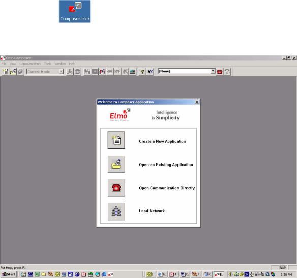
2.2Accessing the Composer
You access the Composer in one of two ways:
By clicking the |
shortcut icon on the desktop |
By selecting Start – Programs – Composer from the Windows taskbar
The Welcome to Composer Application window is displayed immediately, as follows:
2.3Creating a New Application
Creating a new application entails giving it a unique name, defining the communication network to be used and specifying the relevant motor and drive parameters. To define the new application, click Create a New Application from the Welcome to Composer Application window. If you have already accessed the Composer application, you can do one of the following:
Click the  button in the Composer toolbar.
Select Tools – Create New Application from the Composer menu bar.
Composer User Manual |
Using the Wizard |
2-3 |
MAN-COMPUM (Ver. 1.9) |
|
|
|
|
|
|
|
|
The Application Name and Communication Type dialog box will be displayed, as follows:
This dialog box enables you to name your new application and to define the communication type used with it.
1.In the Application Name text box, type a name that clearly defines the new application. The parameters for the communications option last used by the host for the drive application are displayed in the Last Successful Communication Properties text box.
2.To display the parameters of a different communication type (RS-232 or CAN), click the relevant option in the Select Communication Type block. The parameters last used by the host for that type of communication (if any) will be displayed in the Last Successful Communication Properties text box.
3.If you are satisfied with the parameters displayed in the Last Successful Communication Properties text box, click Next to activate the connection and begin specifying your motor parameters (continue to section 2.4). If you wish to change any parameter for your selected communication type, click Properties. The relevant dialog box will be displayed (sections 2.3.1 and 2.3.2).

Composer User Manual |
Using the Wizard |
2-4 |
MAN-COMPUM (Ver. 1.9) |
|
|
|
|
|
|
|
|
2.3.1Defining RS-232 Communication
If you selected RS-232 as your communication type, the RS-232 Properties dialog box will be displayed, as follows:
Use the Com Port, Bits per Second and Parity drop-down lists to select the appropriate setting for each parameter. You can use the Restore Defaults button to recall the default settings; the defaults are COM 1 (Com Port), 19,200 (Bits Per Second) and None (Parity). When you are finished, click Connect to activate the communication link. If a Communications Error occurs, try increasing the baud rate.
2.3.2Defining CAN Communication
Before defining CAN communication parameters, be sure to define the specific CAN control board and firmware installed in your computer. Then select CAN as your communication type. The CAN Properties dialog box will be displayed, as follows:
1.In the Node ID text box of the CAN dialog box, enter a unique number for the drive node. The permissible number of nodes ranges from 1 to 127.
2.From the Baud Rate drop-down list, select the baud rate that is used for all nodes of the network.
3.Click the Board tab to display the CAN Properties – Board dialog box, as follows:

Composer User Manual |
Using the Wizard |
2-5 |
MAN-COMPUM (Ver. 1.9) |
|
|
|
|
|
|
|
|
4.From the Manufacturer drop-down list, select the name of the board manufacturer.
5.From the Board Type drop-down list, select the name of the CAN board installed in your computer.
6.In the CAN Number text box, type the number of the on-board controller (0 or 1) defined in the board setup process. The Segment Address and the IRQ value, defined during CAN installation, are displayed here only for reference.
7.Click Connect to activate the CAN network connection. This process may take a bit of time, and the Composer will display a status bar to indicate connection progress.
8.
2.4Specifying the Motor Parameters
After defining your communication type and making the connection, the next step in drive setup is to define your motor parameters. You do this in the System Database dialog box, displayed when you click Next in the Application Name and Communication Type dialog box:

Composer User Manual |
Using the Wizard |
2-6 |
MAN-COMPUM (Ver. 1.9) |
|
|
|
|
|
|
|
|
1.Check the Elmo servo drive name displayed in the ELMO Driver version text box (read from the controller) and verify that you are working with the correct drive.
2.This dialog lists motor manufacturers and motors that are stored in the drive database.
If these lists include your motor, select the appropriate names from the Motor Manufacturer Name and Motor P/N lists. The motor parameters will be displayed in the lists and text boxes in the Motor Parameters block.
If these lists do not include your motor, click the New command button, and in the Motor Manufacturer Name and Motor P/N text boxes, enter the appropriate information. Then, enter the following motor parameters:
Motor Type:
For your specific type of Servo Drive, select Linear Brushless, Rotating Brushless or Rotating Brush.
Continuous Stall Current: the maximum allowed continuous motor current, in amperes (A).
Maximum Mechanical Speed: the maximum motor speed, in m/sec for linear motors and RPM for rotating motors.
When entering the last two parameters, be sure that these two values are listed exactly as they appear in the motor manufacturer’s data sheet.
When you have finished creating the new entry for the database, click Add.
3.To change the motor parameters, select the motor and click Edit. You may use these changed values for testing in the Wizard. If you wish to save the new values, change the name in the Motor P/N text box and click Add.
To delete a manufacturer name or a part number that you have entered, select the name and then click either Remove manufacturer or Remove motor, as appropriate. Only motors that you have entered in the database can be removed.

Composer User Manual |
Using the Wizard |
2-7 |
MAN-COMPUM (Ver. 1.9) |
|
|
|
|
|
|
|
|
4.Click Next to continue defining your motor. The Commutation Feedback Parameters dialog box will be displayed.
5.From the Current Main Commutation Feedback drop-down list, select the primary encoder type used in your motor (the system may also have an auxiliary feedback mechanism). According to the motor type defined in the System Database dialog box, the system will display the text boxes relevant to defining the current commutation feedback.
For a rotary motor, a dialog box similar to the following will be displayed:
For a linear motor, a dialog box similar to the following will be displayed:
Table 2-1 outlines the various options (parameters are fully explained in the Glossary of this manual).

Composer User Manual |
Using the Wizard |
2-8 |
MAN-COMPUM (Ver. 1.9) |
|
|
|
|
|
|
|
|
|
Current Main |
|
Motor Type |
Commutation Feedback |
Text Box |
Linear Brushless |
Encoder |
Magnetic Pitch (m) |
|
or |
Pulses per Meter (lines/m) |
|
Encoder and Digital Hall |
|
|
Resolution (counts/m) |
|
|
|
|
|
|
(4 x Pulses per Meter value) |
Rotating Brush |
Encoder |
Pulses per Revolution |
|
|
Counts per Revolution |
|
|
(4 x Pulses per Revolution value) |
Rotating Brushless |
Encoder |
Pulses per Revolution |
|
or |
Counts per Revolution |
|
Encoder and Digital Hall |
|
|
(4 x Pulses per Revolution value) |
|
|
|
|
|
Digital Hall |
Number of Pairs of Poles |
Linear DC |
Encoder |
Pulses per Revolution |
Table 2-1: Current Main Commutation Feedback Parameters
6.Enter the values for each of the displayed parameters.
7.Click Next to complete the motor definition and continue to the next stage of setup.
2.5User Interface for Absolute Feedback
2.5.1Rotation MotorsHeidenhain and Stegmann
•Serial Interface– a drop down menu with the following options: Hiperface or EnDat2.1 formats.

Composer User Manual |
Using the Wizard |
2-9 |
MAN-COMPUM (Ver. 1.9) |
|
|
|
|
|
|
|
|
•Absolute Single Turn Position Resolution–a drop down menu that represents, in terms of bits, single-turn feedback cycle. The number of counts would be 2^number of bits. This value is practically the digital absolute resolution derived from the feedback and can be read from the encoder data sheet. Sine/cosine resolution improves this value but is derived from firmware manipulation. The value can be read from the encoder data sheet.
•Absolute Multi-Turn Position Resolution– a drop down menu that represents, in term of bits, the multi-turn feedback resolution. The number of full mechanical resolution without loosing the origin (absolute position) is 2^number of bits turns.
•Sine/Cosine Periods per Revolution– a drop down menu that represents the number of sine/cosine signal cycles per mechanical revolution. After the absolute position is determined by the SimplIQ drive (typically after power up), the position is calculated from the sine/cosine signals and the “Multiplication Factor”.
Note:
The following should apply:
1.SINGLE-TURN + MULTI-TURN ≤ 32 bit resolution
2.SINGLE-TURN ≤ 32 and MULTI-TURN ≤ 16 bit resolutions
By clicking on the “Next” button, the “Commutation Feedback Parameter II” window will appear. The Composer updates the drive with the relevant commutation and feedback parameters needed.
•Multiplication Factor – is a drop down list that represents, in term of bits, the number of position counts in one cycle of the analog (Sine\Cosine) signal. The limitation for the multiplication factor are:
For rotary motors:
Multiplication Factor ≤ |
109 |
(2MULTI _ TURN +1) N |
Where:

Composer User Manual |
Using the Wizard |
2-10 |
MAN-COMPUM (Ver. 1.9) |
|
|
|
|
|
|
|
|
N: Number of sine/cosine signals per mechanical resolution
For linear motors: |
|
|
|
Multiplication Factor ≤ |
109 |
* N |
|
|
L |
||
|
|
||
where:
N: Period of a single analog sine\cosine. Typically in mm/inches
L: Length of the linear sensor. Typically in meters/legs
Both N and L must be the same (distance) units.
•Total counts per revolution– displays the final calculated user resolution
•Additional Commutation Sensor- The commutation sensor in absolute encoders is derived from the analog signals (sine/cosine). In cases where the sensor is not located on the motor and the motor is mounted with Digital Halls, the “Additional Commutation Sensor” enables correction of the commutation angle in each Hall edge. The feature is available for the Cornet, Tuba, Cello, Didge, Eagle, Falcon and Drum products for rotary and linear motors.
•Change…- The push button introduces the “Low Pass Filter” window. The low pass filter filters the analog signals for Speed-Readout. By default there is “no value” and “Not Configured!” appears. By clicking on “Change…”, the user can apply any filter and see the theoretical step response of his/her choice. Typical values for this filter are between 400-700Kz.
Click on the “Next” …
2.5.2 Linear Motors
For Stegmann feedbacks:
Composer User Manual |
Using the Wizard |
2-11 |
MAN-COMPUM (Ver. 1.9) |
|
|
|
|
|
|
|
|
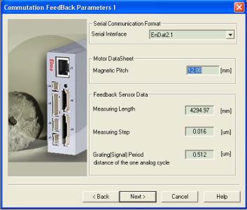
For Heidenhain feedback:
•Serial Interface– a drop down menu with a list of the serial interfaces: Hiperface or EnDat2.1 formats.
•Magnetic Pitch– an Edit Box which represents the distance of one electrical cycle in millimeters. The value is taken from the motor’s data sheet.
•Measurement Length (Hiperface) or Measuring Length (EnDat)– an Edit Box which represents the length of linear sensor in millimeters. The value is taken from the sensor’s data sheet.
•Absolute Position Resolution (Hiperface) or Measuring step (EnDat)– an Edit Box which represents the distance between two sequential absolute position readouts. The value is taken or calculated from the sensor’s data sheet.
•Periodic length (Hiperface) or Grating (Signal) Period (EnDat)- an Edit Box which represents the distance of one analog signal cycle. The value is taken from the sensor’s data sheet.
When clicking on the “Next” button, the “Commutation Feeeback Parameter II” window appears.
•Position Counts per Meter- an Edit Box which represents the number of position counts per meter. Integer type.
•Change… - This push button introduces the “Low Pass Filter” window. The low pass filter filters the analog signals for Speed-Readout. By default there is “no value” and “Not Configured!” appears. By clicking on “Change…” the user can apply any filter and view the chosen theoretical step response. Typical values for this filter are between 400-700Kz.

Composer User Manual |
Using the Wizard |
2-12 |
MAN-COMPUM (Ver. 1.9) |
|
|
|
|
|
|
|
|
2.6Defining System Limits
After defining your motor and commutation parameters (clicking Next in the Commutation Feedback Parameters dialog box), the System Definitions and Limits dialog box will be displayed to enable you to define how your system should behave when it reaches an operational limit. You need to specify each value; these parameters are NOT defined automatically by the system. Be sure that the parameters are correctly defined because incorrectly set values could affect system safety.

Composer User Manual |
Using the Wizard |
2-13 |
MAN-COMPUM (Ver. 1.9) |
|
|
|
|
|
|
|
|
1.In the Driver Parameters block, enter the following values:
Application Continuous Current: the maximum current, in amperes, to be used with the connected motor. This value must be equal to or less than the Motor Continuous Stall Current (defined in the System Database dialog box,
section 2.4) and the value displayed in the Driver Continuous Current text box.
Application Peak Current: the maximum short-term current, in amperes, that can be used with the application. The Wizard automatically displays the Driver Peak Current defined by the manufacturer. The application peak current value must be equal to or less than this value.
2.In the Application Mechanical Limits block, enter the following values:
Speed: the maximum motor speed that will be used in the application. This parameter affects the reference speed limits and must be equal to or lower than the Maximum Mechanical Speed value defined for the motor in the System Database dialog box (section 2.4).
Stop Deceleration (SD): the maximum rate at which the load may decelerate.
Low Reference for Position and High Reference for Position: the full range, in counts, to be used for determining the absolute position command.
Note:
Entering a number higher than 1,073,741,822 indicates that there are no mechanical limits.
3.Click Next. The Logic Input dialog box will be displayed.
This dialog box enables you to define the actions that should occur when the various input signals – are activated.

Composer User Manual |
Using the Wizard |
2-14 |
MAN-COMPUM (Ver. 1.9) |
|
|
|
|
|
|
|
|
4.From the Select Function Behaviors and Logic Level list, select the relevant function options and the logic level at which they are activated. The following table explains the options available for each of the switches:
Function Behavior |
Description when Activated |
Inhibit (Freewheel) |
The drive shuts down and the motor runs freely. |
Hard Stop |
The motor stops under hardware control. |
Ignore |
Uncommitted input. No special function is launched. |
General Purpose |
The relevant general purpose function is launched. |
Forward Only (RLS) |
The motor moves only in forward motion. |
Reverse Only (FLS) |
The motor moves only in reverse motion. |
Begin |
The motor begins operating. |
Soft Stop |
The motor stops under software control. |
Soft & Hard Stop |
The motor stops under both hardware and software control. |
Abort (Freewheel) |
The drive shuts down and the motor stops. |
Home |
Main home option is launched. Available only in Input 5 list. |
AUX Home |
Auxiliary home option is launched. Available only in Input 6 list. |
Table 2-2: Function Behavior Options - Input
5.Click Next to continue to the Logic Output dialog box.
6.In the Logic Output dialog box, repeat the selection process for the output signals, listed in the following table:
Function Behavior |
Description when Activated |
AOK |
The drive is ready for use. |
Brake |
The brake is engaged. |
General purpose |
Uncommitted output. |
Motor enable/disable |
Enable or Disable the motor. |
Table 2-3: Function Behavior Options – Output

Composer User Manual |
Using the Wizard |
2-15 |
MAN-COMPUM (Ver. 1.9) |
|
|
|
|
|
|
|
|
7.Click Next to continue to the tuning steps. The Custom dialog box will be displayed.
If this is a first-time configuration, the Composer Wizard automatically selects the steps that are required for fully tuning the drive and motor that you have defined. If you selected a Rotating Brush motor type in the System Database dialog box (section 2.4), steps 1 and 2 will automatically be deselected. Steps 4 and 5 are mutually exclusive; you may select one or the other, or choose to skip them entirely.
To skip a step, click on the command button to toggle it to Skip . . . (the option turns blue).
If you have not performed commutation tuning yet or if you have changed any parameters in the Commutation Feedback Parameters dialog box, you must perform this step; you may not skip it.
You may stop at any step in the process and the Wizard will save all the parameters in the drive memory.
8.To continue with initial drive setup, select either Step 1 (for digital brushless motors) or Step 3 (for rotating brush motors).
The following sections describe each tuning step in turn.

Composer User Manual |
Using the Wizard |
2-16 |
MAN-COMPUM (Ver. 1.9) |
|
|
|
|
|
|
|
|
2.7Tuning the Current Loop
The Composer Wizard begins the tuning process with the current loop because the current controller must be properly tuned before any other process can be successfully carried out. When you select Step 1, Tuning Current Loop from the Custom dialog box, a Tuning Current Loop dialog box similar to the following is displayed.
This step energizes the motor winding with a high-frequency current, in order to identify the dynamic response for resistance and inductance. The result of the test is a set of welltuned current controller parameters. The controller performance is verified by a test graph showing the Reference, Response and Controller Out vectors. The controller output is proportional to the motor voltage and is shown in order to verify that during the test, the motor voltage did not saturate. If the motor voltage does saturate (is clipped at the top), the response displayed will not reflect the dynamics of the current control loop but rather the dI/dT limits of the power supply and inductance. In such a case, use lower Continuous Current levels (defined in the System Definitions and Limits dialog box, section ) and repeat the current tuning process from the beginning.
To tune the current loop:
1.Click Run in the dialog box. The current will flow into the motor A phase and divide equally between the B and C phases. The motor current generates a fixed magnetic field, so that the motor will jump in the direction of the magnetic field and remain there.
Be aware that the motor shaft may move while the current loop is being tuned, up to half an electrical rotation at most. Therefore, take the necessary precautions for the unlikely event of an undesired movement.
Upon completing the test, the system will store the current tuning information and display the following message:
2.Click Yes to continue directly to the next tuning step.

Composer User Manual |
Using the Wizard |
2-17 |
MAN-COMPUM (Ver. 1.9) |
|
|
|
|
|
|
|
|
2.8Configuring Commutation
For all brushless motors, you need to define the parameters for commutation between the servo drive and the motor. This process automatically determines the correct phase sequence needed for optimal commutation. When digital Hall sensors are used, the system also finds the offset from the commutating points.
The Composer performs commutation setup by driving the motor in stepper mode in both directions; you may select positive or negative counts for each physical direction. The configuration process relies on the parameters entered previously in the Commutation Feedback Parameters dialog box (section 2.4).
The Composer Wizard displays the Establishing Commutation dialog box when you select Step 2, Establishing Commutation from the Custom dialog box, or when you click Next in the Tuning Current Loop dialog box.
To perform commutation setup:
1.Click Run. The motor shaft will move until the Composer finds all the needed commutation parameters. The following message will be displayed:
2.Click OK. The drive will rotate the motor in what the system assumes is the positive direction. After the rotation is complete, the following message will be displayed:

Composer User Manual |
Using the Wizard |
2-18 |
MAN-COMPUM (Ver. 1.9) |
|
|
|
|
|
|
|
|
3.In order to define the positive and negative directions for the motor, click either Yes to accept the present motor direction as positive or click No to change the present motor direction to negative. The motor will then move back to its starting position (for subsequent tuning) and the system will store the commutation information. The following message will be displayed:
4.Click Yes to complete the commutation setup and to continue to the next tuning step.
2.9Tuning the Velocity Loop
This process enables you to tune the velocity loop and to set an optimal balance between control gains and precise motion on the one hand; and higher stress, measurement and quantization noise on the other.
The Composer Wizard enables you to perform this process in three modes:
Manual tuning, in which you manually configure the velocity loop by entering each of the required parameters.
Automatic tuning, in which you select the level of fine tuning, and let the Wizard auto-tuner determine the needed parameters automatically.
Advanced manual tuning, in which you create or modify a gain schedule table to operate with a range of velocities.
Auto tune for Speed Design – under Position Loop, ________________________
___________________________________________________________.
When you select Step 3, Tuning Velocity Loop in the Custom dialog box or when you finish the Establish Commutation step, the Tuning Velocity Loop dialog box is displayed as follows:

Composer User Manual |
Using the Wizard |
2-19 |
MAN-COMPUM (Ver. 1.9) |
|
|
|
|
|
|
|
|
You may tune the velocity loop manually (section 2.9.1), have the Wizard perform automatic tuning (section 2.9.2) or perform advanced manual tuning (section 2.9.3).
2.9.1Manually Tuning the Velocity Loop
1.From the Step 1: Select the Tuning Type drop-down list, select Manual Tuning. The dialog box will remain with its default settings for manual tuning.
2.In the KP and KI text boxes, type the required proportional gain and integral gain filter values for optimal step response.
3.In certain cases, you may wish to manually fine-tune the frequency and resonance definitions by designing a custom filter. To do so, click the Designer button in the Advanced Filter block. If the existing filter cannot be edited (because it has been created by the auto-tuner or if the system sampling time has changed from the last filter modification), the following message will be displayed:
Click Yes to open the Filter Designer in order to create a new filter, or No to view the parameters and Bode plot of the existing filter.
The Filter Designer dialog box will be displayed as follows:
This dialog box enables you to select a filter component and — using the Bode plots
— determine how it may reduce resonance at selected frequencies. Each filter consists of two components: Second order component and Pole component. You may define each component or disable it by selecting None. Full details for designing a new filter are given in the Appendix to this manual.
Composer User Manual |
Using the Wizard |
2-20 |
MAN-COMPUM (Ver. 1.9) |
|
|
|
|
|
|
|
|
4.In the Step 3: Set Test Parameters block of the Tuning Velocity Loop dialog box, enter the Displacement and Velocity values (selecting the Velocity Unit that is convenient to you). Together, these settings define the step command to be used during testing. The -Displacement and +Displacement values (in encoder units) indicate the upper and lower limits in which the system moves during the test phase. The default value is one revolution divided by the number of electric poles in a revolution.
5.You may use the Profiler (select the Profiler Mode checkbox) to profile a response according to values that you set. In Profiler mode, you define the velocity command according to Smooth Factor, Acceleration and Deceleration. Smooth factor is used to “soften the sharp corners” of the motion speed profile, according to the acceleration and deceleration values that you define. Smoothing a profile increases the time required to complete the motion, due to higher acceleration and deceleration times.
6.In Step 4: Set Record Parameters, select the desired recording parameters as follows:
Record Resolution (μsec) is the test data record resolution.
Maximum Record Time (sec) is the test data record time length.
7.Click Run Test to begin the manual velocity loop tuning. The motor will begin to move back and forth, and the system will record the step response. Upon completion, the motor will be disabled and a step response graph will be displayed, as in the following example:
Figure 2-1: Step Response Graph - Manual Velocity Loop Tuning
8.Evaluate the results in the graph and repeat steps 2 to 6 as necessary.
9.Click Run Test to repeat the tuning process and to produce an updated graph.
10.Repeats steps 8 and 9 until your graph indicates optimal tuning.
Composer User Manual |
Using the Wizard |
2-21 |
MAN-COMPUM (Ver. 1.9) |
|
|
|
|
|
|
|
|
2.9.2Automatically Tuning the Velocity Loop
Using the auto-tuning mode for this process provides more precise velocity loop tuning.
To set the auto-tuning options:
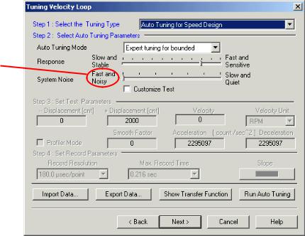
1.From the Step 1: Select the Tuning Type drop-down list, select one of the Auto Tuning type options:
Auto Tuning for Speed Design: for a stand-alone speed mode, in which the drive works only with the velocity loop.
Auto Tuning of Speed Design – Under Position Loop: when the drive receives speed commands from the position controller. When selecting this option, be sure that the position controller is not active during the tuning.
When you make your auto-tune selection, the text boxes of the data box will change accordingly.
Tuning may be noisy
2.In the Step 2: Select Auto Tuning Parameters block, select the tuning mode from the
Auto Tuning Mode drop-down list:
Expert tuning for bounded motion (default): In this mode, the motor swings around a chosen fixed point. Use this option for linear motors and in cases where the motor shaft must remain within position boundaries. In this mode, the boundaries are designated by an algorithm based on system settings; they are displayed before the tuning process begins. If the motion is not restricted, the Expert tuning for free motion option yields even better results.
Expert tuning for free motion: In this mode, the motor rotates freely and is therefore not applicable to linear motors. This option is recommended if there are no restrictions on motion (angle and position); it gives more precise results.
Composer User Manual |
Using the Wizard |
2-22 |
MAN-COMPUM (Ver. 1.9) |
|
|
|
|
|
|
|
|
3.Use the Response slider to select the system margin you require:
Choose a value towards Fast and Sensitive if you require a more responsive (agile) system.
Choose a value towards Slow and Stable if you need a more robust system, which is required in a number of cases, among them:
Machines whose mechanics may vary, as when handling loads of different masses
A machine type that uses one type of control parameters, although the mechanics of each machine may differ from each other.
4.Use the System Noise slider to set the plant noise level: a value towards Slow and Quiet reduces the system noise more effectively. It is recommended to start with an average level and then observe the step response at the plant input. The current is built from two signals: a part that varies slowly due to the reference command and a signal that varies quickly due to system noise. If the noise saturates the plant or its fast-varying signal at the plant output, adjust the System Noise level accordingly. Then run the test again.
5.To manually select the test parameters — rather than having the Wizard calculate them for you — click the Customize Test checkbox, and in the Displacement and Velocity text boxes, enter the values that define the step command to be used for testing:
-Displacement and +Displacement are the upper and lower limits in which the system may move. The default value for automatic mode, for both parameters, is one revolution divided by the number of electric poles in a revolution.
Velocity is the square wave speed reference amplitude command.
6.You may use the Profiler (select the Profiler Mode checkbox) to profile a response according to values that you set. In Profiler mode, you define the velocity command according to Smooth Factor, Acceleration and Deceleration. The smooth factor is used to “soften the sharp corners” of the motion speed profile, according to acceleration and deceleration values that you define. Smoothing a profile increases the time required to complete the motion, due to higher acceleration and deceleration times.
7.In the Step 4: Set Record Parameters block, select the desired recording parameters:
Record Resolution (μsec) is the test data record resolution.
Maximum Record Time (sec) is the test data record time length.
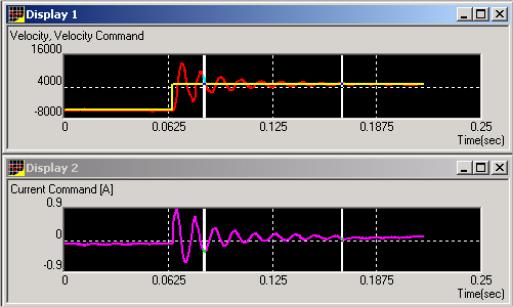
8.Click Run Auto Tuning to start the auto-tuning design process. If the automatic test parameters have been selected (the Customize Test checkbox is not selected), the Wizard will automatically set the test parameters according to the current, speed and displacement limitations of the controller, giving what should be the optimal results. During the test, the motor will move backwards and forward, recording the step response. The results will be displayed in a step response graph comparing the velocity and the current command, as in the following example:
Loading...