


 Loading...
Elmo Motion Control
CANopen DS 301
Implementation Guide
Ver. 2.1 – August 2008

CANopen DS 301 Implementation Guide
MAN-CAN301IG (Ver. 2.1)
Important Notice
This guide is delivered subject to the following conditions and restrictions:
This guide contains proprietary information belonging to Elmo Motion Control Ltd. Such information is supplied solely for the purpose of assisting users of SimplIQ servo drives in implementing CANopen networking.
The text and graphics included in this manual are for the purpose of illustration and reference only. The specifications on which they are based are subject to change without notice.
Information in this document is subject to change without notice. Corporate and individual names and data used in examples herein are fictitious unless otherwise noted.
Doc. No. MAN-CAN301IG
Copyright © 2008
Elmo Motion Control Ltd.
All rights reserved.
Revision History: |
|
|
|
|
|
|
|
|
|
Version |
Rel. Date |
Status |
Changes/Remarks |
|
Ver 2.1 |
August 2008 |
|
y |
Updated note for 0x1017. |
|
|
|
y Updated note for 0x2082. |
|
|
|
|
y 0x2205: Analog input can be converted to physical units. |
|
|
|
|
|
Updated the example. |
|
|
|
y |
Updated 0x2F60. |
|
|
|
y Added note to 0xF70. |
|
Ver 2.0 |
Oct 2007 |
MAN-CAN301IG |
y |
All dummy entries can be mapped |
|
|
|
y Added object 0x2F60, 0x2F70 |
|
|
|
|
y 0x2082 can be mapped |
|
|
|
|
y Added State Machine graphic to Ch. 7 |
|
|
|
|
y Added note to 0x2082 |
|
|
|
|
y Added note to 0x1017 |
|
|
|
|
y |
Added object 0x2205 |
Elmo Motion Control Ltd. |
Elmo Motion Control Inc. |
Elmo Motion Control GmbH |
|
64 Gissin St., P.O. Box 463 |
1 Park Drive, Suite 12 |
Steinkirchring 1 |
|
Petach Tikva 49103 |
Westford, MA 01886 |
D-78056, Villingen-Schwenningen |
|
Israel |
USA |
Germany |
|
Tel: +972 (3) 929-2300 |
Tel: +1 (978) 399-0034 |
Tel: +49 (0) 7720-85 77 60 |
|
Fax: +972 (3) 929-2322 |
Fax: +1 (978) 399-0035 |
Fax: +49 (0) 7720-85 77 70 |
|
info-il@elmomc.com |
info-us@elmomc.com |
info-de@elmomc.com |
www.elmomc.com |
|
|
|
|
CANopen DS 301 Implementation Guide |
i |
|
MAN-CAN301IG (Ver. 2.1) |
||
|
||
|
|
Contents
Chapter 1: Introduction .......................................................................................................... |
1-1 |
||
1.1 |
Relevant Documentation ............................................................................. |
1-1 |
|
|
1.1.1 |
Elmo Documentation........................................................................................ |
1-1 |
|
1.1.2 |
CAN Documentation ........................................................................................ |
1-2 |
1.2 |
Terms and Abbreviations............................................................................. |
1-2 |
|
1.3 |
SimplIQ Communication ............................................................................... |
1-3 |
|
Chapter 2: CANopen Basics................................................................................................... |
2-1 |
|
2.1 |
Physical Layer ........................................................................................... |
2-1 |
2.2 |
Standard vs. Extended Addressing................................................................ |
2-1 |
2.3 |
Client - Server Relations .............................................................................. |
2-1 |
2.4 |
Inhibit Times ............................................................................................. |
2-2 |
2.5 |
RTR – Remote Transmission Request............................................................. |
2-2 |
2.6 |
Object Dictionary ....................................................................................... |
2-2 |
2.7 |
Communication Objects .............................................................................. |
2-3 |
2.8 |
Object Dictionary - Data Types ..................................................................... |
2-4 |
2.9 |
Representation of Numbers.......................................................................... |
2-7 |
Chapter 3: The Object Dictionary......................................................................................... |
3-1 |
|
Chapter 4: Service Data Objects (SDOs).............................................................................. |
4-1 |
|
4.1 |
Initiate SDO Download Protocol................................................................... |
4-2 |
4.2 |
Download SDO Protocol ............................................................................. |
4-3 |
4.3 |
Initiate SDO Upload Protocol ....................................................................... |
4-4 |
4.4 |
Upload SDO Segment Protocol ..................................................................... |
4-5 |
4.5 |
Abort SDO Transfer Protocol........................................................................ |
4-6 |
4.6 |
Uploading Data Using an SDO ..................................................................... |
4-7 |
4.7 |
Downloading Data Using an SDO................................................................. |
4-8 |
4.8 |
Error Correction ......................................................................................... |
4-8 |
Chapter 5: Process Data Objects (PDOs) ............................................................................. |
5-1 |
||
5.1 |
Receive PDOs ............................................................................................ |
5-1 |
|
5.2 |
Transmit PDOs .......................................................................................... |
5-3 |
|
5.3 |
PDO Mapping ........................................................................................... |
5-3 |
|
|
5.3.1 The Mapping Trigger – Transmission Type................................................... |
5-4 |
|
|
5.3.2 |
The Synchronous Trigger................................................................................. |
5-4 |
|
5.3.3 |
The Asynchronous Trigger .............................................................................. |
5-5 |
|
5.3.4 |
RPDO Error Handling ...................................................................................... |
5-5 |
|
5.3.5 |
Mapping Parameter Objects............................................................................. |
5-6 |
|
5.3.6 |
Default Values ................................................................................................... |
5-7 |
Chapter 6: Emergency (EMCY).............................................................................................. |
6-1 |
|
6.1 |
Emergency Configuration............................................................................ |
6-1 |
6.2 |
Emergency Codes Related to Failure ............................................................. |
6-1 |
6.3 |
Emergency Codes for Motor Faults ............................................................... |
6-1 |
6.4 |
Emergency Codes Related to PVT/PT Motion................................................. |
6-1 |
Chapter 7: Network Management (NMT)............................................................................ |
7-1 |
|
Chapter 8: SYNC and Time Stamp ....................................................................................... |
8-1 |
|
CANopen DS 301 Implementation Guide |
Contents |
ii |
MAN-CAN301IG (Ver. 2.1) |
|
|
|
|
|
|
|
|
Chapter 9: Binary Interpreter Commands ........................................................................... |
9-1 |
||
9.1 |
Binary Interpreter Commands and Results ..................................................... |
9-2 |
|
|
9.1.1 Set and Query Commands ............................................................................... |
9-2 |
|
|
9.1.1.1 |
RPDO2 Structure ............................................................................... |
9-2 |
|
9.1.1.1 |
TPDO2 Structure................................................................................ |
9-4 |
|
9.1.2 Execute Command ............................................................................................ |
9-5 |
|
9.2 |
ASCII Interpreter Commands not Supported by Binary Interpreter .................... |
9-6 |
|
Chapter 10: The OS Interpreter ........................................................................................... |
10-1 |
Chapter 11: The EDS............................................................................................................. |
11-1 |
Chapter 12: Communication Profile ................................................................................... |
12-1 |
Object 0x1000: Device type...................................................................................................... |
12-1 |
Object 0x1001: Error register................................................................................................... |
12-2 |
Object 0x1002: Manufacturer status register........................................................................... |
12-3 |
Object 0x1003: Pre-defined error field...................................................................................... |
12-3 |
Object 0x1005: COB-ID SYNC message.................................................................................. |
12-4 |
Object 0x1008: Manufacturer device name .............................................................................. |
12-5 |
Object 0x1009: Manufacturer hardware version...................................................................... |
12-6 |
Object 0x100A: Manufacturer software version ...................................................................... |
12-6 |
Object 0x100B: Node ID .......................................................................................................... |
12-7 |
Object 0x1010: Save parameters .............................................................................................. |
12-7 |
Object 0x1011: Restore parameters .......................................................................................... |
12-8 |
Object 0x1012: COB-ID time stamp ........................................................................................ |
12-9 |
Object 0x1013: High-resolution time stamp........................................................................... |
12-10 |
Object 0x1014: COB-ID emergency object............................................................................. |
12-11 |
Object 0x1016: Consumer heartbeat time............................................................................... |
12-12 |
Object 0x1017: Producer heartbeat time................................................................................. |
12-13 |
Object 0x1018: Identity object ............................................................................................... |
12-14 |
Object 0x1023: OS command and prompt.............................................................................. |
12-15 |
Object 0x1024: OS command mode........................................................................................ |
12-17 |
Object 0x1029: Error behavior ............................................................................................... |
12-17 |
Object 0x1200: SDO server parameter................................................................................... |
12-18 |
Objects 0x1400 - 0x1403: Receive PDO communication parameter ...................................... |
12-20 |
Objects 0x1800 - 0x1803: Transmit PDO communication parameter ................................... |
12-23 |
Objects 0x1A00 - 0x1A03: Transmit PDO mapping............................................................. |
12-25 |
Chapter 13: Manufacturer-specific Objects |
....................................................................... 13-1 |
Object 0x2001: PVT data......................................................................................................... |
13-1 |
Object 0x2002: PT data............................................................................................................ |
13-2 |
Object 0x2004: ECAM data ..................................................................................................... |
13-3 |
Object 0x2012: Binary interpreter input.................................................................................. |
13-4 |
Object 0x2013: Binary interpreter output................................................................................ |
13-4 |
Object 0x2030: Recorder data .................................................................................................. |
13-5 |
Object 0x2040: Coordinate system group ID ......................................................................... |
13-10 |
Object 0x2041: Amplifier-free running timer ........................................................................ |
13-11 |
Object 0x2082: CAN controller status ................................................................................... |
13-11 |
Object 0x208A: Begin time .................................................................................................... |
13-13 |
Object 0x2090: Firmware download....................................................................................... |
13-13 |
CANopen DS 301 Implementation Guide |
Contents |
iii |
MAN-CAN301IG (Ver. 2.1) |
|
|
|
|
|
|
|
|
Object 0x20A0: Auxiliary position actual value .................................................................... |
13-14 |
|
Object 0x20A1: Main position error ...................................................................................... |
13-15 |
|
Object 0x2200: Digital input ................................................................................................. |
13-15 |
|
Object 0x2201: Digital input low byte ................................................................................... |
13-16 |
|
Object 0x2205: Analog Input Object ................................................................................... |
13-17 |
|
Then the reading obtained is:.............................................................................................. |
13-18 |
|
Object 0x2F00: User Integer .................................................................................................. |
13-18 |
|
Object 0x2F01: User Float Array........................................................................................... |
13-19 |
|
Object 0x2F02: ET Array...................................................................................................... |
13-20 |
|
Object 0x2F11: PVT head pointer .......................................................................................... |
13-20 |
|
Object 0x2F12: PVT tail pointer............................................................................................ |
13-21 |
|
Object 0x2F15: Profile position remaining points .................................................................. |
13-21 |
|
Object 0x2F21: Emergency events ......................................................................................... |
13-24 |
|
Object 0x2F22: Bus off time out............................................................................................. |
13-29 |
|
Object 0x2F23: Digital input TPDO event parameters.......................................................... |
13-29 |
|
Object 0x2F30: Last time stamp correction ............................................................................ |
13-31 |
|
Object 0x2F31: Last SYNC time ............................................................................................ |
13-31 |
|
Object 0x2F40: Configuration object...................................................................................... |
13-32 |
|
Object 0x2F41: DS402 Configuration object.......................................................................... |
13-33 |
|
Object 0x2F60 – Zero torque threshold .............................................................................. |
13-34 |
|
Object 0x2F70 – CAN Encoder Range ................................................................................ |
13-35 |
|
Chapter 14: Error Control Protocol ..................................................................................... |
14-1 |
|
Chapter 15: Downloading Firmware .................................................................................. |
15-1 |
|
Chapter 16: Initial CAN Communication Setup............................................................... |
16-1 |
|
16.1 |
Setup Using RS-232................................................................................... |
16-1 |
16.2 |
Bootup Protocol ....................................................................................... |
16-2 |
Appendix A: Little and Big Endians .................................................................................... |
A-1 |
|
CANopen DS 301 Implementation Guide |
Introduction |
1-1 |
MAN-CAN301IG (Ver. 2.1) |
|
|
|
|
|
|
|
|
Chapter 1: Introduction
This manual explains how to implement CANopen DS 301 communication with Elmo’s SimplIQ DSP-based digital servo drives. It provides a description of SimplIQ drives and the means of implementing communication based on the CiA CANopen protocols.
Most SimplIQ functionality is standard, according to CiA documents DS 301, version 4.01, DSP 402 (proprietary) and the CiA OS interpreter. In this document, emphasis is placed on manufacturer-specific behaviors, although it also repeats certain CiA standard material, to enhance understanding and to complete certain descriptions. The manual does not contain all relevant CiA information, indicating that many objects are implemented, but are not documented herein. The user should therefore complement this manual with the CiA documents outlined in the following section.
1.1Relevant Documentation
1.1.1Elmo Documentation
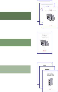
This manual is part of the Elmo SimplIQ documentation set, as outlined in the following diagram:
CANopen Implementation Guide
SimplIQ Software Manual
SimplIQ Command Reference Manual
Programming
Composer User Manual
Setup
Cello Installation Guide
Installation Basssoon Installation Guide
Harmonica Installation Guide

CANopen DS 301 Implementation Guide |
Introduction |
1-2 |
MAN-CAN301IG (Ver. 2.1) |
|
|
|
|
|
|
|
|
In addition to this document, the SimplIQ documentation set includes:
The SimplIQ Installation Guide, which provides full instructions for installing the SimplIQ digital servo drives
The Composer User Manual, which includes explanations of all the software tools that are a part of Elmo’s Composer software environment
The SimplIQ Command Reference Manual, which describes, in detail, each software command used to manipulate the SimplIQ motion controller.
This is the main source of detailed explanations of all SimplIQ commands mentioned in this manual.
The SimplIQ Software Manual, which describes the comprehensive software used with SimplIQ digital servo drives
1.1.2 |
CAN Documentation |
|
|
|
|
Document Name |
Author |
Source |
|
|
CAN Implementation Guidelines |
Gruhler G. and Drier B. |
STA Reutlingen |
|
|
CiA DS 301 V 4.01: |
|
CiA |
|
|
CANopen Communication Profile for |
|
|
|
|
Industrial Systems - based on CAL |
|
|
|
|
CiA DS 302 V 3.0: |
|
CiA |
|
|
CANopen Framework for Programmable |
|
|
|
|
Devices |
|
|
|
|
CiA DS 305 V 1.0: |
|
CiA |
|
|
CANopen Layer Setting Services and |
|
|
|
|
Protocol (LSS) |
|
|
|
|
CiA DSP 402 V 2.0: |
|
CiA |
|
|
CANopen Device Profile |
|
|
|
|
CiA DS 202-2 V 1.1: |
|
CiA |
|
|
CAN Application Layer (CAL ) - |
|
|
|
|
CMS Protocol Specification |
|
|
|
1.2Terms and Abbreviations
The following terms and abbreviations are used in this manual:
Term / Abbreviation |
Definition |
CAL |
CAN application layer. |
CAN client or master |
A host — typically a PC — or other control equipment that |
|
supervises the nodes of a network. |
CAN server or CAN |
A node in the CAN network that can give service under control |
slave |
of the CAN master. |
CMS |
CAN message specification. |
COB |
Communication object; a CAN message. |
CANopen DS 301 Implementation Guide |
Introduction |
1-3 |
MAN-CAN301IG (Ver. 2.1) |
|
|
|
|
|
|
|
|
Term / Abbreviation |
Definition |
COB-ID |
A binary bit-field that includes the ID of the server with which |
|
the master talks, and the type of COB. |
EDS |
Electronic data sheet; a standard form of all CAN objects |
|
supported by a device. The EDS is used by external CAN |
|
configurators. |
ID |
Identifier; the name by which a CAN device is addressed. |
LSB |
Least Significant Bit (or Byte) |
LSS |
Layer setting service: methods for configuring the ID and baud |
|
rate of a slave, using the standard DSP 305. |
MSB |
Most Significant Bit (or Byte) |
Object |
A CAN message with a meaningful functionality and/or data. |
|
Objects are referenced according to addresses in the object |
|
dictionary. DO: Data object. |
OD |
Object dictionary, which is the full set of objects supported by |
|
the node. It is the interface between the application and |
|
communication (see “Object” below.) |
PLC |
Programmable controller. A PLC can serve as a CAN master for |
|
SimplIQ digital servo drives. |
Receive |
In this manual, “received” data is sent from the control |
|
equipment to the servo drive. |
Transmit |
In this manual, “transmitted” data is sent from the servo drive to |
|
the other equipment. |
Table 1-1: Terms and Abbreviations
1.3SimplIQ Communication
SimplIQ digital servo drives support two types of serial communication:
RS-232
CANopen
SimplIQ digital servo drives can simultaneously communicate using both CAN and RS232 communication lines, which are always open for communication. The communication parameters are set using the PP command.

CANopen DS 301 Implementation Guide |
Introduction |
1-4 |
MAN-CAN301IG (Ver. 2.1) |
|
|
|
|
|
|
|
|
The following table compares the main features of both communication modes, as implemented with Elmo SimplIQ digital servo drives:
Features |
CANopen |
RS-232 |
Baud rate |
50,000 - 1,000,000. |
4800 - 57,600 (RS-232). |
Interpreter method |
Binary or ASCII. |
ASCII. |
Fast referencing |
Yes, for PVT, PT and ECAM. |
No. |
Network of servo drives |
Yes. |
No. |
Multiple servo drive |
Yes. |
No. |
synchronization |
|
|
Standardization |
Compliant with CiA |
No standard. |
|
standard. |
|
Special equipment |
CAN communication |
required |
interface (available as an |
|
add-on ISA or PCMCIA card |
|
for PCs) with appropriate |
|
software. |
No: direct connection to serial port of PC.
Ease of use |
Basic capabilities included in |
Immediate: Just type |
|
Elmo Composer program. |
command using |
HyperTerminal or equivalent terminal software.
Table 1-2: SimplIQ Communication Types
RS-232 operation is fast and simple, requiring no detailed understanding of communication processes. CANopen communication achieves higher rates and is able to support the following advanced functions:
High speed online reference generation, required for supporting complex motions
Binary interpretation, which maximizes servo-drive command throughput by eliminating servo drive software overhead
Servo network applications
To benefit from CAN communication and the CiA DS 301 CANopen standard, the user must have a good understanding of the basic programming and timing issues of a CANopen network.
CANopen DS 301 Implementation Guide |
CANopen Basics |
2-1 |
MAN-CAN301IG (Ver. 2.1) |
|
|
|
|
|
|
|
|
Chapter 2: CANopen Basics
This chapter describes — in general — the CANopen communication features most relevant to Elmo SimplIQ servo drive. More detailed information is available in the specific CANopen documentation.
2.1Physical Layer
CAN is a serial communication standard in which the transferred data is coded as electrical pulses on a two-wire communication line. The device that handles the CAN physical layer is called the CAN controller. The device that transmits data over the CAN lines is called the CAN transceiver. SimplIQ digital servo drives use a CAN controller built into the drive DSP.
2.2Standard vs. Extended Addressing
Each CAN message frame includes an arbitration field that defines the type of data sent and its address. CAN version 2.0A supports 11 arbitration bits for this purpose; the seven least significant define the address and the four most significant define the type of message sent. Only 16 message types are supported. CAN version 2.0B supports 29 arbitration bits, of which the seven least significant define the address and 21 bits define the message type. In CiA DS 301, the arbitration bits indicate the object and the node-ID, together comprising the COB-ID.
CAN communication is prioritized so that messages with higher priority are transmitted first. The arbitration field determines the message priority: The lower the number in the arbitration field, the higher the message priority. ID 0 gives the highest priority. The SimplIQ drives support the CAN version 2.0A (11-bit) addressing method only, meaning that it ignores messages of 29 bits. A setup parameter (PP[13] - Node ID) selects the CAN object identification to be used.
2.3Client - Server Relations
A CAN master (or client) is a controller that makes requests to nodes to respond to its commands. A CAN slave (or server) responds to the commands issued by the CAN master. The CAN protocol permits both single-master and multiple-master networks.
The SimplIQ servo drives assume a single-master network arrangement, in which the servo drives are the slaves and the machine controller or PLC is the master. Every servo drive has a unique ID in the range [1…127]. The network master does not require an ID. As a slave, the servo drive never sends an unrequested message, other than emergencies. The drive responds only to messages addressed to its ID or to broadcast messages, which have an ID of 0. All messages sent by a servo drive are marked with its own ID.
 If two servo drives have been assigned the same ID, the CAN network may crash.
CANopen DS 301 Implementation Guide |
CANopen Basics |
2-2 |
MAN-CAN301IG (Ver. 2.1) |
|
|
|
|
|
|
|
|
2.4Inhibit Times
The inhibit time for a given message type is the minimum time that must elapse from the time the message is first transmitted until the time that it may be transmitted again. The purpose of inhibit times is to ensure that high-priority messages do not flood the bus and thereby prevent service messages of lower priority from being transmitted. The inhibit times of SimplIQ drives are defined only for asynchronous transmit process data objects (TPDOs), by sub-index 3 of the associated transmission type object. The resolution of the inhibit time is 100 microseconds, with an accuracy of 2 milliseconds.
Note: If several events occur during the inhibit time of a message, only the last message will be transmitted when the inhibit time extinct. For example, if TPDO3 is activated by digital input 1 and digital input 3 with an inhibit time of 10 milliseconds, then if a digital input 1 event emits TPDO3 at time 0, a digital input 3 event occurring 5 milliseconds later will not cause any TPDO3 transmission for the next 5 millisecond. The TPDO3 transmission would be postponed, allowing other messages to be transmitted, until the inhibit time is exhausted.
The DS 301 version 4.0 protocol allows the user to modify the inhibit time only for COBs that are not valid (sub-index 1 of objects 0x1400 and 0x1800), while SimplIQ drives allow the user to modify the inhibit time at any time, with pending messages being discarded according to that time definition.
2.5RTR – Remote Transmission Request
The RTR is not supported by the Elmo drive.
2.6Object Dictionary
An object dictionary (OD) is a naming system that gives a unique identifier to each data item — or “object” —that is communicated over the CAN bus. An object is identified by an index and, if it is a complex object, also by a sub-index. A CANopen client can manipulate an object of a CANopen server by referring to its identifier, according to the access permission of the object. (An object’s access permission may be read-only, writeonly, or read-write.)
CiA DS 301 requires a set of mandatory objects for all CANopen devices. Other OD items are predefined by CiA DS 301 to have fixed identifiers, if supported. The OD also accommodates manufacturer-specific objects.
CANopen DS 301 Implementation Guide |
CANopen Basics |
2-3 |
MAN-CAN301IG (Ver. 2.1) |
|
|
|
|
|
|
|
|
2.7Communication Objects
The data-byte units transported through a CAN network are called communication objects (COBs). SimplIQ servo drive uses the following COB types:
COB Type |
Description |
Service data object (SDO) |
SDO messages are used to manipulate OD objects |
|
according to their IDs. The server receives the SDO, |
|
which specifies in its message which object is to be |
|
dealt with. |
|
SDO messages can be chained to form a “domain |
|
transfer,” which is useful for sending large data items |
|
such as long strings. Domain transfers are time- |
|
consuming, because the CAN bus is half-duplex. Each |
|
time a data segment is downloaded, a full-sized data |
|
segment is uploaded for verification, and vice versa. |
Process data object (PDO) |
PDO messages are used to manipulate OD objects |
|
without explicit reference to the object identifier, which |
|
is possible if there is an a-priori convention concerning |
|
the OD item referenced. Such conventions are called |
|
“PDO mappings”; these are actually OD objects |
|
themselves, and may be defined and manipulated using |
|
an SDO. |
Emergency (EMCY) |
Emergency messages are used by the servo drives to |
|
warn of an exception. The EMCY is the only COB type |
|
that a servo drive may transmit without first being |
|
explicitly asked. EMCY objects are similar to servo |
|
drive “interrupts”: they eliminate the need to poll the |
|
servo drive continuously for the emergency status. |
Network Management (NMT) |
NMT objects are used by CAN clients to initialize a |
|
servo drive as a server. |
Layer Setting Service (LSS) |
This service is used to assign IDs and baud rates to |
|
newly-installed products. |
Table 2-1: Communication Objects Used by SimplIQ Servo Drives
The type of COB transmitted is indicated in the arbitration field of the message, and thereby determines its priority. The relation between bits 8 to 11 of the arbitration field (COB-ID) and the COB type is presented in the following table:
CANopen DS 301 Implementation Guide |
CANopen Basics |
2-4 |
MAN-CAN301IG (Ver. 2.1) |
|
|
|
|
|
|
|
|
COB Type |
Bits 8 - 11 of COB-ID |
ID Range |
NMT |
0000 |
0 |
SYNC |
0001 |
128 (80h) |
Time Stamp |
0010 |
256 (100h) |
Emergency |
0001 |
129…255 (81h…ffh) |
PDO1 - Transmit |
0011 |
385…511 (181h…1ffh) |
PDO1 - Receive |
0100 |
513…639 (201h…27fh) |
PDO2 - Transmit |
0101 |
641…767 (281h…2ffh) |
PDO2 - Receive |
0110 |
769…895 (301h…37fh) |
PDO3 - Transmit |
0111 |
897…1023 (381h…3ffh) |
PDO3 - Receive |
1000 |
1025…1151 (401h…47fh) |
PDO4 - Transmit |
1001 |
1153…1279 (481h…4ffh) |
PDO4 - Receive |
1010 |
1281…1407 (501h…57fh) |
SDO - Transmit |
1011 |
1409…1535 (581h…5ffh) |
SDO - Receive |
1100 |
1537…1663 (601h…67fh) |
Error control (node guarding) |
1110 |
1793…1919 (701h…77fh) |
Table 2-2: COB Types |
|
|
Example:
The COB-ID of PDO1, when received by node #2, is binary 01000000010, which is decimal 514, or 202 hexadecimal. The IDs of the servo drives are set in the range 1…127.
2.8Object Dictionary - Data Types
The Elmo CAN controller supports the following data types:
Index |
Object |
Name |
0002 |
DEFTYPE |
Integer8 |
0003 |
DEFTYPE |
Integer16 |
0004 |
DEFTYPE |
Integer32 |
0005 |
DEFTYPE |
Unsigned8 |
0006 |
DEFTYPE |
Unsigned16 |
0007 |
DEFTYPE |
Unsigned32 |
0008 |
DEFTYPE |
Floating Point (Float) |
0009 |
DEFTYPE |
Visible String |
0020 |
DEFSTRUCT |
PDO CommPar |
0021 |
DEFSTRUCT |
PDO Mapping |
0022 |
DEFSTRUCT |
SDO Parameter |

CANopen DS 301 Implementation Guide |
CANopen Basics |
2-5 |
MAN-CAN301IG (Ver. 2.1) |
|
|
|
|
|
|
|
|
Index |
Object |
Name |
0040 |
DEFTYPE |
PVT DataPar |
0041 |
DEFTYPE |
PT DataPar |
0042 |
DEFTYPE |
Binary interpreter query |
0043 |
DEFTYPE |
Binary interpreter command |
0044 |
DEFTYPE |
DSP 402 PV data record |
0081 |
DEFTYPE |
DSP 402 interpolated data configuration record |
Table 2-3: Data Types
Note: Data Objects 0002 to 0004 are used as map able “dummy” entries.
Communication Parameter Record Object 0x20 |
|
||
Index |
Sub-index |
Field in PDO Communication Parameter Record |
Data Type |
0020h |
0h |
Number of supported entries in record |
UNSIGNED8 |
|
1h |
COB-ID |
UNSIGNED32 |
|
2h |
Transmission type |
UNSIGNED8 |
|
3h |
Inhibit time |
UNSIGNED16 |
|
4h |
Reserved |
UNSIGNED8 |
|
5h |
Event timer |
UNSIGNED16 |
PDO Mapping Parameter Record Object 0x21 |
|
||
Index |
Sub-index |
Field in PDO Parameter Mapping Record |
Data Type |
0021h |
0h |
Number of mapped objects in PDO |
UNSIGNED8 |
|
1h |
First object to be mapped |
UNSIGNED32 |
|
2h |
Second object to be mapped |
UNSIGNED32 |
… |
… |
… |
… |
|
40h |
64th object to be mapped |
UNSIGNED32 |
The four device-specific data types used by SimplIQ digital servo drives are as follows:
PVT DataPar Object 0x40 |
|
|
|
MSB |
|
|
LSB |
Time (UNSIGNED8) |
Velocity (SIGNED24) |
Position (SIGNED32) |
|
|
|
|
|
PT DataPar Object 0x41 |
|
|
|
MSB |
|
|
LSB |
Position 2 (SIGNED32) |
|
Position 1 (SIGNED32) |
|
|
|
|
|
CANopen DS 301 Implementation Guide |
CANopen Basics |
2-6 |
MAN-CAN301IG (Ver. 2.1) |
|
|
|
|
|
|
|
|
Binary Interpreter Query Object 0x42 |
|
|
|
|
|
|
|
||||||
MSB |
|
|
|
|
|
|
|
|
|
|
LSB |
||
7 |
|
6 |
5 |
|
4 |
|
3 |
2 |
1 |
|
0 |
|
|
|
|
|
|
|
|
|
|
|
|
|
|
|
|
|
|
|
|
|
|
|
Attribute |
Attribute |
Letter |
|
Letter |
||
|
|
|
|
|
|
|
high |
low |
low |
|
high |
||
For more information about the binary interpreter query, refer to Chapter 9. |
|
|
|
||||||||||
Binary Interpreter Command Object 0x43 |
|
|
|
|
|
|
|
||||||
MSB |
|
|
|
|
|
|
|
|
|
|
LSB |
||
7 |
|
6 |
5 |
|
4 |
|
3 |
2 |
1 |
|
0 |
|
|
|
|
|
|
|
|
|
|
|
|
|
|
|
|
Data |
|
Data |
Data |
|
Data |
|
Attribute |
Attribute |
Letter |
|
Letter |
||
high |
|
|
|
|
low |
|
high |
low |
low |
|
high |
||
|
|
|
|
|
|
|
|
|
|
|
|
||
For more information about the binary interpreter command, refer to Chapter 9. |
|
|
|
||||||||||
DSP 402 Interpolated Mode PV Object 0x44 |
|
|
|
|
|
|
|
||||||
MSB |
|
|
|
|
|
|
|
|
|
|
LSB |
||
Position 2 (SIGNED32) |
|
|
Velocity (SIGNED32) |
|
|
|
|
|
|||||
|
|
|
|
|
|
|
|
||||||
DSP 402 Interpolated Time Period Record Object 0x80 |
|
|
|
|
|
|
|||||||
Index |
Sub-index |
Field in Interpolation Time Period Record |
Data Type |
|
|||||||||
0080h |
0h |
Number of entries |
|
|
UNSIGNED8 |
|
|||||||
|
1h |
Interpolation time units |
|
UNSIGNED8 |
|
||||||||
|
2h |
Interpolation time index |
|
INTEGER8 |
|||||||||
DSP 402 Interpolated Data Configuration Record Object 0x81 |
|
|
|
|
|
||||||||
Index |
Sub-index |
Field in Interpolation Time Period Record |
Data Type |
|
|||||||||
0081h |
0h |
Number of entries |
|
|
UNSIGNED8 |
|
|||||||
|
1h |
Maximum buffer size |
|
|
UNSIGNED32 |
|
|||||||
|
2h |
Actual buffer size |
|
|
UNSIGNED32 |
|
|||||||
|
3h |
Buffer organization |
|
|
UNSIGNED8 |
|
|||||||
|
4h |
Buffer position |
|
|
UNSIGNED16 |
|
|||||||
|
5h |
Size of data record |
|
|
UNSIGNED8 |
|
|||||||
|
6h |
Buffer clear |
|
|
|
|
UNSIGNED8 |
|
|||||
CANopen DS 301 Implementation Guide |
CANopen Basics |
2-7 |
MAN-CAN301IG (Ver. 2.1) |
|
|
|
|
|
|
|
|
2.9Representation of Numbers
CAN communication delivers numerical data stored in binary form. Integers are stored by their binary representation, while floating-point numbers are stored according to the IEEE representation. SimplIQ digital servo drives support three types of data: short integers (two bytes), long integers (four bytes) and floating-point numbers (four bytes). These multiple-byte numbers are stored in the CAN messages according to CAN standards, using the “little endian” (Intel-type) convention. With this method, the number is inverted before storage: The most significant byte of the number receives the lowest address and the least significant byte receives the highest address. More information about the little endian method is provided in the Appendix of this manual.
Example:
The following is an 8-byte CAN message:
Bytes 0 - 1 |
0x1234 |
|
|
Bytes 2 - 3 |
0x5678 |
|
|
Bytes 4 - 7 |
0x9abcdef0 |
|
|
The CAN message data field will be as follows:
Byte |
Contents |
|
|
0 |
0x34 |
|
|
1 |
0x12 |
|
|
2 |
0x78 |
|
|
3 |
0x56 |
|
|
4 |
0xf0 |
|
|
5 |
0xde |
|
|
6 |
0xbc |
|
|
7 |
0x9a |
|
|
CANopen DS 301 Implementation Guide |
The Object Dictionary |
3-1 |
MAN-CAN301IG (Ver. 2.1) |
|
|
|
|
|
|
|
|
Chapter 3: The Object Dictionary
The object dictionary is essentially a grouping of objects that are accessible via receive and transmit SDOs. Part of the object can be mapped to transmit and receive PDOs (TPDO and RPDO, respectively) in a predefined manner.
The following layout is used with the objects in the object dictionary:
Index (Hex) |
Object |
|
0 |
|
Not used |
0001 |
- 001F |
Static data type |
0020 |
- 003F |
Complex data type |
0040 |
- 005F |
Manufacturer-specific data type |
0060 |
- 0FFF |
Reserved |
1000 |
- 1FFF |
Communication profile area |
2000 |
- 2FFF |
Manufacturer-specific profile area |
6000 |
- 6FFF |
Standardized device profile area |
A000 - FFF |
Reserved |
|
The table that follows lists the objects supported by SimplIQ digital servo drives. Each object is addressed by a 16-bit index. Some of the objects may include 8-bit sub-indices, which are described in the object description. The object Name is that given by CiA or Elmo according to object type. Access can be R (read only), W (write only) or R/W (read/write). In the Can be Mapped column, N indicates that the object cannot be mapped to a PDO, while Y indicates that the object can be mapped to a PDO or that it is permanently mapped to a predefined PDO.
Name |
Index |
Description |
Access |
Mapped |
CAN controller |
0x1000 |
Device type and functionality. Constant |
R |
N |
type |
|
value = 0x12D. |
|
|
Error register |
0x1001 |
Contains error information. |
R |
N |
Manufacturer |
0x1002 |
Returns status similar to SR command. |
R |
Y |
status register |
|
|
|
|
Pre-defined error |
0x1003 |
Returns previous emergency history. |
R |
N |
field |
|
Setting object 0x1003 sub-index 0 to 0 |
|
|
|
|
deletes error history. |
|
|
COB-ID for |
0x1005 |
32-bit Dword, pre-defined. |
R |
N |
SYNC message |
|
|
|
|
Communication |
0x1006 |
Spacing, in μsec, between consecutive |
R/W |
N |
cycle period |
|
SYNC signals. This parameter is included |
|
|
|
|
for compatibility with the standard OD, but |
|
|
|
|
it is ignored. |
|
|

CANopen DS 301 Implementation Guide |
The Object Dictionary |
3-2 |
MAN-CAN301IG (Ver. 2.1) |
|
|
|
|
|
|
|
|
Name |
Index |
Description |
Access |
Mapped |
Manufacturer’s |
0x1008 |
String that returns the drive name such as |
R |
N |
device name |
|
“Harmonica” |
|
|
Hardware |
0x1009 |
A string that conveys the information in |
R |
N |
version |
|
WS[30]. |
|
|
Software version |
0x100A |
String that returns value of VR command. |
R |
N |
Node ID |
0x100B |
|
R |
N |
Store parameters |
0x1010 |
Stores parameters in flash memory. |
R/W |
N |
Restore |
0x1011 |
Restore parameters from flash memory. |
R/W |
N |
parameters |
|
|
|
|
COB-ID for Time |
0x1012 |
Specifies COB-ID of Time Stamp |
R |
N |
Stamp message |
|
message. |
|
|
High-resolution |
0x1013 |
Defines a Time Stamp message with a |
R/W |
N |
Time Stamp |
|
resolution of 1 μsec. |
|
|
COB-ID of |
0x1014 |
Defines COB-ID of the Emergency object |
R |
N |
Emergency |
|
(EMCY). |
|
|
message |
|
|
|
|
Consumer |
0x1016 |
Defines minimal acceptance rate for |
R/W |
N |
heartbeat time |
|
heartbeat messages. |
|
|
Producer |
0x1017 |
Defines rate of generating heartbeats. |
R/W |
N |
heartbeat time |
|
|
|
|
LSS address |
0x1018 |
Address for ID and baud rate |
R |
N |
|
|
configuration, according to DSP 305. |
|
|
OS interpreter |
0x1023 |
OS prompt interpreter. |
R/W |
N |
OS command |
0x1024 |
Mode command and status readout of OS |
R/W |
N |
mode |
|
interpreter. |
|
|
Error behavior |
0x1029 |
Defines behavior in a case of serious |
R/W |
N |
|
|
device failure, according to CiA |
|
|
|
|
DS 301. |
|
|
SDO1 server |
0x1200 |
SDO1: server parameter. (link) |
R |
N |
PDO1 RX Comm. |
0x1400 |
PDO1: receive communication parameter. |
R/W |
N |
|
|
(link) |
|
|
PDO2 Rx Comm. |
0x1401 |
PDO2: receive communication parameter. |
R/W |
N |
PDO3 Rx Comm. |
0x1402 |
PDO3: receive communication parameter. |
R/W |
N |
PDO4 RX Comm. |
0x1403 |
PDO4: receive communication parameter. |
R/W |
N |
PDO1 Rx Map. |
0x1600 |
PDO1: receive mapping parameter. (link) |
R/W |
N |
PDO2 Rx Map. |
0x1601 |
PDO2: receive mapping parameter. |
R/W |
N |
PDO3 Rx Map. |
0x1602 |
PDO3: receive mapping parameter. |
R/W |
N |
PDO4 Rx Map. 0x1603 PDO4: receive mapping parameter. (link) R/W N
CANopen DS 301 Implementation Guide |
The Object Dictionary |
3-3 |
MAN-CAN301IG (Ver. 2.1) |
|
|
|
|
|
|
|
|
|
Name |
Index |
Description |
Access |
Mapped |
|
PDO1 Rx Comm. |
0x1800 |
PDO1: transmit communication |
R/W |
N |
|
|
|
parameter. |
|
|
|
PDO2 Tx Comm. |
0x1801 |
PDO2: transmit communication |
R/W |
N |
|
|
|
parameter. |
|
|
|
PDO3 Tx Comm. |
0x1802 |
PDO3: transmit communication |
R/W |
N |
|
|
|
parameter. |
|
|
|
PDO4 Tx Comm. |
0x1803 |
PDO4: transmit communication |
R/W |
N |
|
|
|
parameter. |
|
|
|
PDO1 Tx Map. |
0x1A00 |
PDO1: transmit mapping parameter. |
R/W |
N |
|
PDO2 Tx Map. |
0x1A01 |
PDO2: transmit mapping parameter. |
R/W |
N |
|
PDO3 Tx Map. |
0x1A02 |
PDO3: transmit mapping parameter. |
R/W |
N |
|
PDO4 Tx Map |
0x1A03 |
PDO4: transmit mapping parameter. |
R/W |
N |
|
PVT data |
0x2001 |
Bytes describing PVT command. |
W |
Y |
|
PT data |
0x2002 |
Bytes describing PT command. |
W |
Y |
|
Fast position |
0x2003 |
Reserved for future real-time positioning |
|
|
|
|
|
modes. |
|
|
|
ECAM data |
0x2004 |
Fast, auto-increment entry to ECAM |
W |
Y |
|
|
|
table. |
|
|
|
Binary interpreter |
0x2012 |
Set binary interpreter command. |
W |
Y |
|
input |
|
|
|
|
|
Binary interpreter |
0x2013 |
Get binary interpreter command. |
R |
Y |
|
output |
|
|
|
|
|
Recorded data |
0x2030 |
Contains recorded data according to |
R |
N |
|
output |
|
request in RC binary command. |
|
|
|
Group ID |
0x2040 |
Identifier used to address a group of |
R/W |
N |
|
|
|
drives for coordinated commands. |
|
|
|
Amplifier free |
0x2041 |
Transmits accurate 32-bit timer of drive. |
R |
Y |
|
running timer |
|
|
|
|
|
CAN controller |
0x2082 |
CAN controller status register. |
R |
Y |
|
status |
|
|
|
|
|
Begin on time |
0x208A |
Used to start a synchronized motion |
R/W |
N |
|
|
|
according to internal free running timer. |
|
|
|
Firmware |
0x2090 |
Similar to DF command. |
W |
N |
|
download |
|
|
|
|
|
Auxiliary |
0x20A0 |
Actual position as taken from auxiliary |
R |
Y |
|
position actual |
|
sensor input (PY). |
|
|
|
value |
|
|
|
|
|
Position error |
0x20A1 |
Position error as calculated from |
R |
Y |
|
|
|
command and actual position value. (PE). |
|
|
CANopen DS 301 Implementation Guide |
The Object Dictionary |
3-4 |
MAN-CAN301IG (Ver. 2.1) |
|
|
|
|
|
|
|
|
Name |
Index |
Description |
Access |
Mapped |
Digital input |
0x2200 |
Reflects the digital input (IP) |
R |
Y |
Digital inputs |
0x2201 |
Reflected Negative limit switch, Positive |
R |
Y |
low byte |
|
limit switch and Home switch. |
|
|
User Integer |
0x2F00 Provides an array of 24 integer numbers |
R |
Y |
|
|
|
for general-purpose use. |
|
|
User Float Array |
0x2F01 |
Provides an array of 24 floating numbers |
R/W |
Y |
|
|
for general-purpose use. |
|
|
ET Array |
0x2F02 Enables ECAM table variables (ET[1] to |
R/W |
Y |
|
|
|
ET[255]) to be loaded. |
|
|
PVT buffer head |
0x2F11 PVT motion advance information. |
R |
Y |
|
pointer |
|
|
|
|
PVT buffer tail |
0x2F12 PVT motion advance information. |
R |
Y |
|
pointer |
|
|
|
|
Buffered PTP |
0x2F15 Used to detect number of remaining |
R |
Y |
|
remained point |
|
points in DSP 402 Profile Position |
|
|
|
|
buffered mode. |
|
|
Asynchronous |
0x2F20 Defines which events emit a PDO. |
R/W |
N |
|
PDO event |
|
|
|
|
Emergency event |
0x2F21 Defines which events emit an emergency. |
R/W |
N |
|
Bus-off timeout |
0x2F22 Defines bus-off timeout, after which CAN |
R/W |
N |
|
|
|
communication will be renewed if SimplIQ |
|
|
|
|
enters bus-off. |
|
|
Digital Input |
0x2F23 Defines which digital input transmissions |
R/W |
N |
|
TPDO Event |
|
will activate a TPDO driven by a digital |
|
|
Parameters |
|
input event. |
|
|
Last Time Stamp |
0x2F30 Difference between last SYNC time and |
R |
Y |
|
correction |
|
last Time Stamp. |
|
|
|
|
Serves to estimate how accurately the |
|
|
|
|
internal amplifier's clock is locked on the |
|
|
|
|
master clock. |
|
|
Internal µsec |
0x2F31 Internal µsec counter of drive, sampled at |
R |
Y |
|
counter at last |
|
last SYNC. Useful when one drive is used |
|
|
SYNC |
|
to synchronize entire network. |
|
|
Configuration |
0x2F40 Configure functionality of the node. |
R/W |
N |
|
object |
|
|
|
|
Table 3-1: Object Dictionary
CANopen DS 301 Implementation Guide |
Service Data Objects (SDOs) |
4-1 |
MAN-CAN301IG (Ver. 2.1) |
|
|
|
|
|
|
|
|
Chapter 4: Service Data Objects (SDOs)
SimplIQ digital servo drives use a single transmit server SDO (COB 581h-6ffh) and a single receive server SDO (COB601h-67fh). This is according to CiA definitions and priority allocations for 11-bit addressing.
When using SDOs, it is important to remember that:
An SDO has a lower priority than a PDO.
An SDO session is not complete until it is confirmed.
For example, if an SDO is used to change a PDO mapping, the SDO should be issued only after the last session in which the PDO is completed, and the newly-mapped PDO should not be used until the SDO mapping change is confirmed.
SDOs implement the CMS multiplexed domain protocols.
Notes:
In an SDO data exchange, each client message may be backed by one and only one server message.
An SDO carries a toggle bit, which varies in every consecutive message of a domain transfer, so that the loss of a single message can be tracked.
An SDO transfer can be terminated using the special “Abort domain transfer” message.
An SDO message carries a maximum of seven bytes of data. One byte (the header byte) is always dedicated to overhead data.
The length of an SDO message is always eight bytes, even if some of them are unused. Unused data bytes are marked as such in the message header.
The maximum length of payload data in an expedited SDO is four bytes.
CANopen DS 301 Implementation Guide |
Service Data Objects (SDOs) |
4-2 |
MAN-CAN301IG (Ver. 2.1) |
|
|
|
|
|
|
|
|
4.1Initiate SDO Download Protocol
This protocol is used to implement the Initiate SDO Download service.
Client to server: |
|
|
|
|
|||
0 |
|
|
|
|
1 |
4 |
8 |
|
|
|
|
|
|
|
|
7…5 |
4 |
|
3…2 |
1 |
0 |
|
|
|
|
|
|
|
|
|
|
css = 1 |
x |
|
n |
e |
s |
m |
d (data) |
|
|
|
|
|
|
|
|
Server to client: |
|
|
|
|
|||
0 |
|
|
|
|
1 |
4 |
8 |
|
|
|
|
|
|
||
7…5 |
4…0 |
|
|
|
|
||
|
|
|
|
|
|
|
|
scs = 3 |
x |
|
|
|
|
m |
reserved |
where: |
|
|
|
|
|
|
|
css |
|
Client command specifier |
|
||||
|
|
1: Initiate download request |
|
||||
scs |
|
Server command specifier |
|
||||
|
|
3: Initiate download response |
|
||||
nNumber of bytes in d that do not contain data. Only valid if
e = 1 and s = 1; otherwise it is 0. Bytes [8-n, 7] do not contain data.
eTransfer type
0:Normal transfer
1:Expedited transfer
sSize indicator
0:Data set size is not indicated
1:Data set size is indicated
mMultiplexor. Represents index/sub-index of data to be transferred by SDO.
dData
e = 0, s = 0: d is reserved for future use.
e = 0, s = 1: d contains number of bytes to be downloaded. Byte 4 contains LSB and byte 7 contains MSB.
e = 1, s = 1: d contains data of length 4-n to be downloaded. The encoding depends on the type of data referenced by index and sub-index.
e = 1, s = 0: d contains an unspecified number of bytes to be downloaded.
x |
Not used; always 0. |
reserved |
Reserved for future use; always 0. |
CANopen DS 301 Implementation Guide |
Service Data Objects (SDOs) |
4-3 |
MAN-CAN301IG (Ver. 2.1) |
|
|
|
|
|
|
|
|
4.2Download SDO Protocol
This protocol is used to implement the Download SDO Segment service.
Client to server: |
|
|
|||
0 |
|
|
|
1 |
8 |
|
|
|
|
|
|
7…5 |
4 |
|
3…1 |
0 |
|
|
|
|
|
|
|
css = 0 |
t |
|
n |
c |
seg-data (segment data) |
|
|
|
|
|
|
Server to client: |
|
|
|||
0 |
|
|
|
1 |
8 |
|
|
|
|
|
|
7…5 |
4 |
|
3…0 |
|
|
|
|
|
|
|
|
scs = 1 |
t |
|
x |
|
reserved |
where: |
|
|
|
|
|
css |
|
Client command specifier |
|||
|
|
0: Download segment request |
|||
scs |
|
Server command specifier |
|||
|
|
1: Download segment response |
|||
seg-data |
|
Maximum seven bytes of segment data downloaded. Encoding depends |
|||
|
|
on type of data referenced by index and sub-index. |
|||
nNumber of bytes in seg-data that do not contain segment data. Bytes [8-n, 7] do not contain segment data. n = 0 if no segment size is indicated.
cWhether or not there are still more segments to be downloaded:
0:More segments to be downloaded
1:No more segments to be downloaded
tToggle bit, which alternates for each subsequent segment to be downloaded. First segment has toggle-bit set to 0. Toggle bit is equal for request and response message.
x |
Not used; always 0. |
reserved |
Reserved for future use; always 0. |
CANopen DS 301 Implementation Guide |
Service Data Objects (SDOs) |
4-4 |
MAN-CAN301IG (Ver. 2.1) |
|
|
|
|
|
|
|
|
4.3Initiate SDO Upload Protocol
This protocol is used to implement the Initiate SDO Download service.
Client to server: |
|
|
|
|
|
|||
0 |
|
|
|
|
1 |
|
4 |
8 |
|
|
|
|
|
|
|
|
|
7…5 |
4…0 |
|
|
|
|
|
||
|
|
|
|
|
|
|
|
|
css = 2 |
x |
|
|
|
|
m |
|
reserved |
|
|
|
|
|
|
|
|
|
Server to client: |
|
|
|
|
|
|||
0 |
|
|
|
|
1 |
|
4 |
8 |
|
|
|
|
|
|
|
|
|
7…5 |
4 |
|
3…2 |
1 |
0 |
|
|
|
|
|
|
|
|
|
|
|
|
scs = 2 |
x |
|
n |
e |
s |
m |
|
reserved |
where: |
|
|
|
|
|
|
|
|
css |
|
Client command specifier |
|
|
||||
|
|
2: Initiate upload request |
|
|
||||
scs |
|
Server command specifier |
|
|
||||
|
|
2: Initiate upload response |
|
|
||||
nNumber of bytes in d that do not contain data. Only valid if
e = 1 and s = 1; otherwise it is 0. Bytes [8-n, 7] do not contain segment data.
eTransfer type
0:Normal transfer
1:Expedited transfer
sSize indicator
0:Data set size is not indicated
1:Data set size is indicated
mMultiplexor. Represents index/sub-index of data to be transferred by SDO.
dData
e = 0, s = 0: d is reserved for future use.
e = 0, s = 1: d contains the number of bytes to be uploaded. Byte 4 contains LSB and byte 7 contains MSB.
e = 1, s = 1: d contains data of length 4-n to be downloaded. The encoding depends on the type of data referenced by index and sub-index.
e = 1, s = 0: d contains an unspecified number of bytes to be uploaded.
x |
Not used; always 0. |
reserved |
Reserved for future use; always 0. |
CANopen DS 301 Implementation Guide |
Service Data Objects (SDOs) |
4-5 |
MAN-CAN301IG (Ver. 2.1) |
|
|
|
|
|
|
|
|
4.4Upload SDO Segment Protocol
This protocol is used to implement the Upload SDO Segment service.
Client to server: |
|
|
|
|
|||
0 |
|
|
|
1 |
8 |
||
|
|
|
|
|
|
|
|
7…5 |
4 |
|
3…0 |
|
|
|
|
|
|
|
|
|
|
|
|
css = 3 |
t |
|
x |
|
|
reserved |
|
|
|
|
|
|
|
|
|
Server to client: |
|
|
|
|
|||
0 |
|
|
|
1 |
8 |
||
|
|
|
|
|
|
|
|
7…5 |
4 |
|
3…1 |
|
0 |
|
|
|
|
|
|
|
|
|
|
scs = 0 |
t |
|
n |
|
c |
|
seg-data |
where: |
|
|
|
|
|
|
|
css |
|
Client command specifier |
|||||
|
|
3: Upload segment request |
|||||
scs |
|
Server command specifier |
|||||
|
|
0: Upload segment response |
|||||
tToggle bit, which alternates for each subsequent segment to be uploaded. First segment has toggle-bit set to 0. Toggle bit is equal for request and response message.
cWhether or not there are still more segments to be uploaded:
0:More segments to be uploaded
1:No more segments to be uploaded
seg-data Maximum seven bytes of segment data uploaded. Encoding depends on type of data referenced by index and sub-index.
nNumber of bytes in seg-data that do not contain segment data. Bytes [8-n, 7] do not contain segment data. n = 0 if no segment size is indicated.
x |
Not used; always 0. |
reserved |
Reserved for future use; always 0. |
CANopen DS 301 Implementation Guide |
Service Data Objects (SDOs) |
4-6 |
MAN-CAN301IG (Ver. 2.1) |
|
|
|
|
|
|
|
|
4.5Abort SDO Transfer Protocol
This protocol is used to implement the Abort SDO Transfer service.
Client to server or server to client: |
|
|
|
|
0 |
1 |
|
4 |
8 |
|
|
|
|
|
7…5 |
4…0 |
|
|
|
|
|
|
|
|
cs = 4 |
x |
m |
|
d (data) |
|
|
|
|
|
where: |
|
|
|
|
cs |
Command specifier |
|
|
|
4: Abort transfer request
xNot used; always 0.
m |
Multiplexor. Represents index/sub-index of SDO. |
dFour-byte abort code giving reason for abort, encoded as Unsigned32 value.
The SDO Abort codes are listed in the following table:
Abort Code |
Description |
|
0503 |
0000h |
Toggle bit not alternated. |
0504 |
0001h |
Invalid or unknown client/server command specifier. |
0504 |
0005h |
Out of memory. |
0601 |
0000h |
Unsupported access to an object. |
0601 |
0001h |
Attempt to read a write-only object. |
0601 |
0002h |
Attempt to write a read-only object. |
0602 |
000h |
Object does not exist in object dictionary. |
0604 |
0041h |
Object cannot be mapped to PDO. |
0604 |
0042h |
Number and length of objects to be mapped exceeds PDO length. |
0604 |
0043h |
General parameter incompatibility. |
0604 |
0047h |
General internal incompatibility in device. |
0606 |
0000h |
Access failed due to hardware error. |
0607 |
0010h |
Data type does not match, length of service parameter does not match. |
0607 |
0012h |
Data type does not match, service parameter too long. |
0607 |
0013h |
Data type does not match, service parameter too short. |
0609 |
0011h |
Sub-index does not exist. |
0609 |
0030h |
Value range of parameter exceeded (only for write access). |
0609 |
0031h |
Value of parameter written too high. |
0609 |
0032h |
Value of parameter written too low. |
0609 |
0036h |
Maximum value is less than minimum value. |
0800 |
0000h |
General error. |
0800 |
0020h |
Data cannot be transferred to or stored in application. |
CANopen DS 301 Implementation Guide |
Service Data Objects (SDOs) |
4-7 |
MAN-CAN301IG (Ver. 2.1) |
|
|
|
|
|
|
|
|
Abort Code |
Description |
0800 0021h |
Data cannot be transferred to or stored in application due to local |
|
control. |
0800 0022h |
Data cannot be transferred to or stored in application due to present |
|
device state. |
0800 0023h |
Object dictionary dynamic generation failed or no object dictionary is |
|
present (for example, object dictionary is generated from file and |
|
generation has failed due to a file error). |
Table 4-1: SDO Abort Codes
When the abort code is 0800 0000h, the actual error can be retrieved using the EC command.
4.6Uploading Data Using an SDO
Data is uploaded in two basic formats:
A short data item (up to four bytes) is uploaded by a single message conversation, called an expedited SDO.
Longer data items require a longer conversation and are called segmented transfers.
Example of an expedited SDO:
An SDO is used to read the number of SDOs supported by the servo drive. The result (one transmit SDO and one receive SDO) is in object 0x1000 in the OD and is formatted as the 32-bit word 0x00020192. The client message body is outlined in the following table (% indicates a binary number):
Byte |
Value |
Description |
Comment |
0 |
%01000000 |
Header |
Leading %010 is client command specifier |
|
|
|
(ccs) for Initiate Domain Upload. |
1 |
0x00 |
Index (LO) |
|
2 |
0x10 |
Index (HI) |
Use little endian. |
3 |
0 |
Sub-index |
No sub-index; therefore set to 0. |
4 - 8 |
0 |
Reserved |
|
Table 4-2: Expedited SDO - Client Message

CANopen DS 301 Implementation Guide |
Service Data Objects (SDOs) |
4-8 |
MAN-CAN301IG (Ver. 2.1) |
|
|
|
|
|
|
|
|
The server response is outlined in the following table:
Byte |
Value |
Description |
Comment |
0 |
%01000011 |
Header |
Bits 7…5: %010 is client command specifier |
|
|
|
(css) for Initiate Domain Upload. |
|
|
|
Bits 3, 2: n bits that indicate that all data |
|
|
|
bytes are relevant. |
|
|
|
Bits 1, 0: %11, to expedite transfer and d |
|
|
|
contains information. |
1 |
0x00 |
Index (LO) |
|
2 |
0x10 |
Index (HI) |
Use little endian. |
3 |
0 |
Sub-index |
No sub-index, so it is set to 0. |
4 |
0x92 |
Data: 0x00020192 in |
|
|
|
little endian format |
|
50x01
60x02
70
Table 4-3: Expedited SDO - Server Response
4.7Downloading Data Using an SDO
Data downloading with SDOs is very similar to data uploading. It can be handled in a single message conversation (expedited transfer) or in a segmented conversation. A detailed example of an expedited download transfer is given in section 5.3.6.
4.8Error Correction
Included in an SDO transaction are features that enable error detection and correction. Errors can be detected with both software and hardware. Hardware error conditions relate to overrun, excessive line noise, broken lines or other malfunctions of the physical layer. The toggle bit is used for software detection; it correlates each domain segment with its previous and next segments. An unexpected toggle bit signals an error.
An Elmo slave that receives a corrupted message always terminates the SDO sequence with an “Abort domain transfer” message, structured as follows:
CANopen DS 301 Implementation Guide |
Service Data Objects (SDOs) |
4-9 |
MAN-CAN301IG (Ver. 2.1) |
|
|
|
|
|
|
|
|
Byte |
Description |
0 |
0x80 |
1 – 2 |
Index |
3 |
Sub-index |
4 |
Additional code |
5 |
Error code |
6 – 7 |
Error class |
Table 4-4: Abort Domain Transfer Message Structure
Fields 4 to 7 are described fully under “Abort SDO Transfer Protocol” in this manual.
CANopen DS 301 Implementation Guide |
Process Data Objects (PDOs) |
5-1 |
MAN-CAN301IG (Ver. 2.1) |
|
|
|
|
|
|
|
|
Chapter 5: Process Data Objects (PDOs)
5.1Receive PDOs
A Receive Process Data Objects (RPDO) is used to receive predefined and unconfirmed messages. An RPDO is received through use of an event, which may be asynchronous (such as “Message Received”) or synchronous with the reception of a SYNC. Four receive PDOs are used with the Elmo drive. The following must be indicated:
Objects that can be mapped and have write access can be mapped to each RPDO.
Execution of the mapped objects begins in the lower index of the relevant mapping object (0x1600 - 0x1603).
High-priority objects, used for high-speed motion modes, can be mapped to an RPDO to avoid the overhead in using the standard interpreter. This mapping is dynamic, according to the setting of the PDO mapping at index 0x1600 - 0x1603 by the appropriate SDO. In a drive, only one fast reference object can be mapped to a single RPDO. The fast reference objects that can be mapped to an RPDO are:
Index |
Meaning |
Access |
2001h |
PVT motion command |
Write |
2002h |
PT motion command |
Write |
2003h |
Reserved |
|
2004h |
ECAM entry |
Write |
All type of objects can be mapped. Unsigned8, Signed8, Unsigned16, signed16, Unsigned32, and SignedT32 can be mapped. Manufacture specific object such as Binary interpreter and PVT\PT can also be mapped.
RPDO1-4 can be freely mapped. The only constraints are that only one of the 0x2001
– 0x2004 objects can be mapped to an RPDO at a time, and that none of these objects can be mapped to more than one RPDO simultaneously.
Data of RPDOs mapped to objects 0x2001-0x2004 is processed immediately upon reception.
Data of RPDOs is queued and it is passed for interpretation and execution at the next available background loop (Idle Loop) and according to the transmission type.
The transmission type associated to the Rx mapping can be either synchronous where the data of the RPDO is passed for executing after the occurrence of the following SYNC (value =1), or asynchronous (value=255 or 254) in which the data of the RPDO is passed to the application immediately after reception and processed on the next Idle loop.
At most one copy of each mapped RPDO can be stored for synchronous execution. If same RPDO arrives before next SYNC, it overwrites the previous with no notification.
Loading...