


 Loading...
Gold Solo Hornet
Digital Servo Drive
Installation Guide
EtherCAT and CAN
July 2014 (Ver. 1.009)
www.elmomc.com

Notice
This guide is delivered subject to the following conditions and restrictions:
•This guide contains proprietary information belonging to Elmo Motion Control Ltd. Such information is supplied solely for the purpose of assisting users of the Gold Solo Hornet servo drive in its installation.
•The text and graphics included in this manual are for the purpose of illustration and reference only. The specifications on which they are based are subject to change without notice.
•Information in this document is subject to change without notice.
Elmo Motion Control and the Elmo Motion Control logo are registered trademarks of Elmo Motion Control Ltd.
EtherCAT Conformance Tested. EtherCAT® is a registered trademark and patented technology, licensed by Beckhoff Automation GmbH, Germany.
Document no. MAN-G-SOLHORIG-EC (Ver. 1.009) Copyright 2014 Elmo Motion Control Ltd. All rights reserved.
Catalog Number

Notes |
•The part number of the Gold Solo Hornet (EtherCAT version) has an E, for example, G-SOLHOR1/100E whereas the CAN version has an S, for example G-SOLHOR1/100S.
•There are two models of the Gold Solo Hornet: connectors only (for currents of 10 A or less) and wires only (for currents of 15 A or more). On request, the wires model may be ordered for currents of 10 A or less.
Cable Kit
•Catalog number: CBL-GSOLHORKIT01 (can be ordered separately)
•For further details, see the documentation for this cable kit (TBD).
Revision History
Version |
Date |
Details |
|
|
|
|
|
1.000 |
December 2012 |
Initial release |
|
|
|
|
|
1.001 |
December 2012 |
General corrections |
|
|
|
|
|
1.002 |
December 2012 |
General corrections |
|
|
|
|
|
1.003 |
December 2012 |
General corrections |
|
|
|
|
|
1.004 |
December 2012 |
General corrections |
|
|
|
|
|
1.005 |
December 2012 |
General corrections |
|
|
|
Added Section 3.1: Physical Specifications |
|
|
|
|
|
1.006 |
March 2013 |
General corrections |
|
|
|
|
|
1.007 |
March 2013 |
Section 3.2: Technical Dataupdated the Power Ratings |
|
|
|
table for the 200 VDC option. |
|
|
|
|
|
1.008 |
April 2014 |
Corrections to sections 4.6, 4.7.2.3, 4.7.2.4, and 5.5.2 |
|
|
|
|
Elmo Worldwide
Head Office
Elmo Motion Control Ltd.
60 Amal St., P.O. Box 3078, Petach Tikva 49516
Israel
Tel: +972 (3) 929-2300 • Fax: +972(3)929-2322 • info-il@elmomc.com
North America
Elmo Motion Control Inc.
42 Technology Way, Nashua, NH 03060
USA
Tel: +1 (603) 821-9979 • Fax: +1 (603) 821-9943 • info-us@elmomc.com
Europe
Elmo Motion Control GmbH
Hermann-Schwer-Strasse 3, 78048 VS-Villingen
Germany
Tel: +49 (0) 7721-9447120 • Fax:+49 (0)7721-944 7130 • info-de@elmomc.com
China
Elmo Motion Control Technology (Shanghai) Co. Ltd.
Room 1414, Huawen Plaza, No. 999 Zhongshan West Road, Shanghai (200051)
China
Tel: +86-21-32516651 • Fax: +86-21-32516652 • info-asia@elmomc.com
Asia Pacific
Elmo Motion Control APAC Ltd.
B-601 Pangyo Innovalley, 621 Sampyeong-dong, Bundang-gu, Seongnam-si, Gyeonggi-do,
South Korea (463-400)
Tel: +82-31-698-2010 • Fax: +82-31-801-8078 • info-asia@elmomc.com

Gold Solo Hornet Installation Guide (EtherCAT and CAN) |
5 |
MAN-G-SOLHORIG-EC (Ver. 1.009) |
Table of Contents
Chapter 1: Safety Information.......................................................................................... |
8 |
|
1.1. |
Warnings......................................................................................................................... |
9 |
1.2. |
Cautions.......................................................................................................................... |
9 |
1.3. |
Directives and Standards.............................................................................................. |
10 |
1.4. |
CE Marking Conformance............................................................................................. |
10 |
1.5. |
Warranty Information .................................................................................................. |
10 |
Chapter 2: Product Description ...................................................................................... |
11 |
||
2.1. |
Functional Description.................................................................................................. |
11 |
|
2.2. |
Product Features .......................................................................................................... |
11 |
|
|
2.2.1. |
High Power Density ....................................................................................... |
11 |
|
2.2.2. |
Supply Input................................................................................................... |
11 |
|
2.2.3. |
Servo Control ................................................................................................. |
12 |
|
2.2.4. Advanced Filters and Gain Scheduling........................................................... |
13 |
|
|
2.2.5. |
Motion Control .............................................................................................. |
13 |
|
2.2.6. |
Fully Programmable....................................................................................... |
13 |
|
2.2.7. |
Feedback Ports Options................................................................................. |
14 |
|
2.2.8. |
Feedback Sensor Specifications..................................................................... |
14 |
|
2.2.9. |
Communications............................................................................................ |
15 |
|
2.2.10. |
Safety ............................................................................................................. |
16 |
|
2.2.11. |
Outputs .......................................................................................................... |
16 |
|
2.2.12. |
Differential Outputs....................................................................................... |
16 |
|
2.2.13. |
Inputs............................................................................................................. |
16 |
|
2.2.14. |
Differential Inputs.......................................................................................... |
16 |
|
2.2.15. |
Analog Input .................................................................................................. |
16 |
|
2.2.16. |
Built-In Protection ......................................................................................... |
17 |
|
2.2.17. |
Status Indication ............................................................................................ |
17 |
|
2.2.18. |
Automatic Procedures ................................................................................... |
17 |
|
2.2.19. |
Accessories .................................................................................................... |
17 |
2.3. |
System Architecture ..................................................................................................... |
18 |
|
2.4. How to Use this Guide.................................................................................................. |
19 |
||
Chapter 3: Technical Information ................................................................................... |
20 |
||
3.1. |
Physical Specifications.................................................................................................. |
20 |
|
3.2. |
Technical Data .............................................................................................................. |
20 |
|
|
3.2.1. |
Auxiliary Supply ............................................................................................. |
21 |
Chapter 4: Installation ................................................................................................... |
22 |
|
4.1. |
Site Requirements ........................................................................................................ |
22 |
4.2. Unpacking the Drive Components................................................................................ |
22 |
|
4.3. |
Connectors and Indicators............................................................................................ |
24 |

Gold Solo Hornet Installation Guide (EtherCAT and CAN) |
Table of Contents |
6 |
||||
MAN-G-SOLHORIG-EC (Ver. 1.009) |
|
|
|
|||
|
4.3.1. |
Connector Types |
|
24 |
|
|
|
|
|
||||
|
4.3.2. |
Pinouts........................................................................................................... |
|
|
25 |
|
|
|
4.3.2.1. Power, Motor, Control and Port B Connector (J1) ....................... |
25 |
|
||
|
|
4.3.2.2. Auxiliary Feedback and IO (J2)...................................................... |
|
27 |
|
|
|
|
4.3.2.3. |
Communication Connector (J3) .................................................... |
|
29 |
|
|
4.3.3. |
EtherCAT Indicators ....................................................................................... |
|
30 |
|
|
|
|
4.3.3.1. |
EtherCAT Link Indicators............................................................... |
|
30 |
|
|
|
4.3.3.2. |
EtherCAT Status Indicator............................................................. |
|
30 |
|
|
4.3.4. |
Drive Status Indicator .................................................................................... |
|
31 |
|
|
4.4. |
Mounting the Gold Solo Hornet ................................................................................... |
|
32 |
|
||
4.5. |
Wiring the Gold Solo Hornet ........................................................................................ |
|
33 |
|
||
4.6. |
The Gold Solo Hornet Connection Diagrams................................................................ |
|
34 |
|
||
4.7. |
Main, Auxiliary and Motor Power ................................................................................ |
|
36 |
|
||
|
4.7.1. |
Motor Power (J1)........................................................................................... |
|
36 |
|
|
|
4.7.2. Main and Auxiliary Power.............................................................................. |
|
38 |
|
||
|
|
4.7.2.1. |
Main Power (J1)............................................................................ |
|
38 |
|
|
|
4.7.2.2. Auxiliary Power Supply (J2) (Optional) ......................................... |
|
39 |
|
|
|
|
4.7.2.3. Power Rating 200 V ...................................................................... |
|
40 |
|
|
|
|
4.7.2.4. Power Rating 100 V ...................................................................... |
|
41 |
|
|
4.8. STO (Safe Torque Off) Inputs (J2) ................................................................................. |
|
43 |
|
|||
4.9. Feedback and Analog Input .......................................................................................... |
|
46 |
|
|||
|
4.9.1. Feedback Port A (J2) ...................................................................................... |
|
46 |
|
||
|
|
4.9.1.1. |
Incremental Encoder .................................................................... |
|
49 |
|
|
|
4.9.1.2. |
Absolute Serial Encoder................................................................ |
|
49 |
|
|
|
4.9.1.3. |
Hall Sensors................................................................................... |
|
50 |
|
|
4.9.2. Feedback Port B (J1) ...................................................................................... |
|
51 |
|
||
|
|
4.9.2.1. |
Incremental Encoder .................................................................... |
|
52 |
|
|
|
4.9.2.2. |
Interpolated Analog Encoder........................................................ |
|
53 |
|
|
|
4.9.2.3. |
Resolver Connection..................................................................... |
|
53 |
|
|
4.9.3. Port C – Emulated Encoder Output (J2)......................................................... |
|
54 |
|
||
4.10. |
User I/Os (J2) ................................................................................................................ |
|
|
57 |
|
|
|
4.10.1. |
Digital Inputs (J2) ........................................................................................... |
|
57 |
|
|
|
4.10.2. |
Digital Output (J2).......................................................................................... |
|
60 |
|
|
|
4.10.3. |
Analog Input (J2)............................................................................................ |
|
62 |
|
|
4.11. |
Communications........................................................................................................... |
|
|
63 |
|
|
|
4.11.1. |
RS-232 (J3) ..................................................................................................... |
|
63 |
|
|
|
4.11.2. Differential RS-232 Communication (RS-422) – J3 ........................................ |
|
65 |
|
||
|
4.11.3. USB 2.0 Communication (J3) ......................................................................... |
|
66 |
|
||
|
4.11.4. |
EtherCAT Communications Version............................................................... |
|
67 |
|
|
|
|
4.11.4.1. |
EtherCAT Communication (J3)...................................................... |
|
67 |
|
|
|
4.11.4.2. |
Ethernet Communication (J3)....................................................... |
|
69 |
|
|
4.11.5. |
CAN Communications Version....................................................................... |
|
70 |
|
|
4.12. |
Powering Up ................................................................................................................. |
|
|
72 |
|
|
4.13. |
Initializing the System................................................................................................... |
|
72 |
|
||
4.14. |
Heat Dissipation............................................................................................................ |
|
|
72 |
|
|

Gold Solo Hornet Installation Guide (EtherCAT and CAN) |
Table of Contents |
7 |
|||
MAN-G-SOLHORIG-EC (Ver. 1.009) |
|
|
|||
|
4.14.1. |
Thermal Data |
72 |
|
|
|
|
||||
|
4.14.2. |
Heat Dissipation Data .................................................................................... |
73 |
|
|
|
4.14.3. How to Use the Charts................................................................................... |
74 |
|
||
Chapter 5: Technical Specifications ................................................................................ |
75 |
|
|||
5.1. |
Dimension..................................................................................................................... |
|
75 |
|
|
5.2. |
Environmental Conditions ............................................................................................ |
76 |
|
||
5.3. |
Control Specifications................................................................................................... |
77 |
|
||
|
5.3.1. |
Current Loop.................................................................................................. |
77 |
|
|
|
5.3.2. |
Velocity Loop ................................................................................................. |
78 |
|
|
|
5.3.3. |
Position Loop ................................................................................................. |
78 |
|
|
5.4. |
Feedbacks ..................................................................................................................... |
|
79 |
|
|
|
5.4.1. |
Feedback Supply Voltage............................................................................... |
79 |
|
|
|
5.4.2. |
Feedback Options .......................................................................................... |
79 |
|
|
|
|
5.4.2.1. |
Incremental Encoder Input........................................................... |
79 |
|
|
|
5.4.2.2. |
Digital Halls ................................................................................... |
80 |
|
|
|
5.4.2.3. Interpolated Analog (Sine/Cosine) Encoder ................................. |
80 |
|
|
|
|
5.4.2.4. |
Resolver ........................................................................................ |
81 |
|
|
|
5.4.2.5. |
Absolute Serial Encoder................................................................ |
81 |
|
|
5.4.3. Port C Feedback Output ................................................................................ |
82 |
|
||
5.5. |
I/Os ............................................................................................................................... |
|
|
83 |
|
|
5.5.1. Digital Input Interfaces – TTL Mode .............................................................. |
83 |
|
||
|
5.5.2. Digital Input Interfaces – PLC Mode .............................................................. |
84 |
|
||
|
5.5.3. |
Digital Output Interface................................................................................. |
85 |
|
|
|
5.5.4. |
Analog Input .................................................................................................. |
85 |
|
|
5.6. Safe Torque Off (STO)................................................................................................... |
86 |
|
|||
|
5.6.1. STO Input Interfaces – TTL Mode .................................................................. |
86 |
|
||
|
5.6.2. STO Input Interfaces – PLC Mode.................................................................. |
86 |
|
||
5.7. |
EtherCAT Communications Version ............................................................................. |
87 |
|
||
5.8. |
CAN Communications Version...................................................................................... |
88 |
|
||
5.9. |
Pulse-Width Modulation (PWM).................................................................................. |
88 |
|
||
5.10. |
Compliance with Standards.......................................................................................... |
89 |
|
||

Gold Solo Hornet Installation Guide (EtherCAT and CAN) |
8 |
MAN-G-SOLHORIG-EC (Ver. 1.009) |
Chapter 1: Safety Information
In order to achieve the optimum, safe operation of the Gold Solo Hornet servo drive, it is imperative that you implement the safety procedures included in this installation guide. This information is provided to protect you and to keep your work area safe when operating the Gold Solo Hornet and accompanying equipment.
Please read this chapter carefully before you begin the installation process.
Before you start, ensure that all system components are connected to earth ground. Electrical safety is provided through a low-resistance earth connection.
Only qualified personnel may install, adjust, maintain and repair the servo drive. A qualified person has the knowledge and authorization to perform tasks such as transporting, assembling, installing, commissioning and operating motors.
The Gold Solo Hornet servo drive contains electrostatic-sensitive components that can be damaged if handled incorrectly. To prevent any electrostatic damage, avoid contact with highly insulating materials, such as plastic film and synthetic fabrics. Place the product on a conductive surface and ground yourself in order to discharge any possible static electricity build-up.
To avoid any potential hazards that may cause severe personal injury or damage to the product during operation, keep all covers and cabinet doors shut.
The following safety symbols are used in this manual:
Warning:
This information is needed to avoid a safety hazard, which might cause bodily injury.
Caution:
This information is necessary for preventing damage to the product or to other equipment.
Table of Contents |www.elmomc.com

Gold Solo Hornet Installation Guide (EtherCAT and CAN) |
Safety Information |
9 |
MAN-G-SOLHORIG-EC (Ver. 1.009) |
|
|
|
|
|
1.1. Warnings
•To avoid electric arcing and hazards to personnel and electrical contacts, never connect/disconnect the servo drive while the power source is on.
•Power cables can carry a high voltage, even when the motor is not in motion. Disconnect the Gold Solo Hornet from all voltage sources before it is opened for servicing.
•The Gold Solo Hornet servo drive contains grounding conduits for electric current protection. Any disruption to these conduits may cause the instrument to become hot (live) and dangerous.
•After shutting off the power and removing the power source from your equipment, wait at least 1 minute before touching or disconnecting parts of the equipment that are normally loaded with electrical charges (such as capacitors or contacts). Measuring the electrical contact points with a meter, before touching the equipment, is recommended.
1.2. Cautions
•The Gold Solo Hornet servo drive contains hot surfaces and electrically-charged components during operation.
•The maximum DC power supply connected to the instrument must comply with the parameters outlined in this guide.
•When connecting the Gold Solo Hornet to an approved isolated 12 to 95 VDC auxiliary power supply, connect it through a line that is separated from hazardous live voltages using reinforced or double insulation in accordance with approved safety standards.
•Before switching on the Gold Solo Hornet, verify that all safety precautions have been observed and that the installation procedures in this manual have been followed.
•Do not clean any of the Gold Solo Hornet drive's soldering with solvent cleaning fluids of pH greater than 7 (8 to 14). The solvent corrodes the plastic cover causing cracks and eventual damage to the drive's PCBs.
Elmo recommends using the cleaning fluid Vigon-EFM which is pH Neutral (7).
For further technical information on this recommended cleaning fluid, select the link:
http://www.zestron.com/fileadmin/zestron.com-usa/daten/electronics/Product_TI1s/TI1- VIGON_EFM-US.pdf
Table of Contents |www.elmomc.com

Gold Solo Hornet Installation Guide (EtherCAT and CAN) |
Safety Information |
10 |
MAN-G-SOLHORIG-EC (Ver. 1.009) |
|
|
|
|
|
1.3.Directives and Standards
The Gold Solo Hornet conforms to the following industry safety standards:
Safety Standard |
Item |
|
|
|
|
Approved IEC/EN 61800-5-1, Safety |
Adjustable speed electrical power drive systems |
|
|
|
|
Recognized UL 508C |
Power Conversion Equipment |
|
|
|
|
In compliance with UL 840 |
Insulation Coordination Including Clearances and |
|
|
Creepage Distances for Electrical Equipment |
|
|
|
|
In compliance with UL 60950-1 |
Safety of Information Technology Equipment |
|
(formerly UL 1950) |
Including Electrical Business Equipment |
|
|
|
|
In compliance with EN 60204-1 |
Low Voltage Directive 73/23/EEC |
|
|
|
The Gold Solo Hornet servo drive has been developed, produced, tested and documented in accordance with the relevant standards. Elmo Motion Control is not responsible for any deviation from the configuration and installation described in this documentation. Furthermore, Elmo is not responsible for the performance of new measurements or ensuring that regulatory requirements are met.
1.4.CE Marking Conformance
The Gold Solo Hornet servo drive is intended for incorporation in a machine or end product. The actual end product must comply with all safety aspects of the relevant requirements of the European Safety of Machinery Directive 98/37/EC as amended, and with those of the most recent versions of standards EN 60204-1 and EN 292-2 at the least.
According to Annex III of Article 13 of Council Directive 93/68/EEC, amending Council Directive 73/23/EEC concerning electrical equipment designed for use within certain voltage limits, the Gold Solo Hornet meets the provisions outlined in Council Directive 73/23/EEC. The party responsible for ensuring that the equipment meets the limits required by EMC regulations is the manufacturer of the end product.
1.5.Warranty Information
The products covered in this manual are warranted to be free of defects in material and workmanship and conform to the specifications stated either within this document or in the product catalog description. All Elmo drives are warranted for a period of 12 months from the time of installation, or 18 months from time of shipment, whichever comes first. No other warranties, expressed or implied — and including a warranty of merchantability and fitness for a particular purpose — extend beyond this warranty.
Table of Contents |www.elmomc.com
Gold Solo Hornet Installation Guide (EtherCAT and CAN) |
11 |
MAN-G-SOLHORIG-EC (Ver. 1.009) |
Chapter 2: Product Description
2.1.Functional Description
The Gold Solo Hornet is an integrated solution designed to simply and efficiently connect Elmo’s Gold Hornet servo drive directly to the application. The solution consists of the Gold Hornet together with a convenient connection interface which either eliminates or reduces development time and resources when designing an application’s PCB board.
The Gold Solo Hornet is an advanced high power density servo drive. It provides top servo performance, advanced networking and built in safety, all in a small PCB mountable package. Gold Solo Hornet has a fully featured motion controller and local intelligence.
The Gold Solo Hornet operates from a DC power source. The drive can operate as a standalone device or as part of a multi-axis system in a distributed configuration on a real-time network.
The Gold Solo Hornet drive is easily set up and tuned using Elmo Application Studio (EAS) software tools. As part of the Gold product line, it is fully programmable with the Elmo motion control language. For more about software tools refer to the Elmo Application Studio Software Manual.
The Gold Solo Hornet is available in a variety of options. There are multiple power rating options, two different communications options – Standard (S suffix in the part number) or EtherCAT (E suffix in the part number), a variety of feedback selections and I/O configuration possibilities.
2.2.Product Features
Note: The features described in this chapter relate to the range of Gold Solo Hornet models. Depending on the model you have purchased, not all features are available.
To see the features for your model, look at the product label on the Gold Solo Hornet and use the product catalog number schematic that appears at the beginning of this manual and on page 23 to determine which specific features are available to you.
2.2.1.High Power Density
The Gold Solo Hornet delivers up to 1.6 kW of continuous power or 3.2 kW of peak power in a compact package (73.4 x 46.5 x 35.8 mm or 2.89" x 1.8" x 1.4").
2.2.2.Supply Input
•Gold Solo Hornet Power rating is 12 to 195 VDC
•Two power ratings for Gold Solo Hornet; 100V and 200V:
For power rating 200V
Two power isolated DC power sources are required, main power 12 - 195V and Auxiliary Power 12-95V for the logic.
Table of Contents |www.elmomc.com

Gold Solo Hornet Installation Guide (EtherCAT and CAN) |
Product Description |
12 |
MAN-G-SOLHORIG-EC (Ver. 1.009) |
|
|
|
|
|
For power rating of 100V
Single DC Power Supply - Power to the Gold Solo Hornet is provided by a 12–95 VDC single isolated DC power source (not included with the Gold Solo Hornet). A “smart” control-supply algorithm enables the Gold Solo Hornet to operate with only one power supply with no need for an auxiliary power supply for the logic.
Optional Backup (Auxiliary) Supply
If backup functionality is required in case of power loss, e.g., to keep the original position, a 12–95 VDC external isolated supply should be connected (via the Gold Solo Hornet’s VL+ terminal). This is more flexible than the requirement for 24 VDC supply. If backup is not needed, a single power supply is used for both the power and logic circuits.
There are two voltage ratings of the Gold Solo Hornet, therefore the correct power supply must be used, according to the maximum operating voltage of the Gold Solo Hornet. Refer to Chapter 3: Technical Information.
2.2.3.Servo Control
•Advanced and extremely fast vector control algorithm (current loop bandwidth: 4 kHz)
•Current/Torque sampling rate: up to 25 kHz (40 μs)
•Velocity sampling rate: up to 12.5 kHz (80 μs)
•Position sampling rate: up to 12.5 kHz (80 μs)
•Electrical commutation frequency: up to 4 kHz
•Current closed loop bandwidth exceeds 4 kHz
•Position/Velocity/Acceleration command range – full 32 bit
•Position over velocity, with full dual loop support
•Current gain scheduling to compensate for the motor’s non-linear characteristics
•Advanced filtering: Low pass, Notch, General Biquad
•Current loop gain scheduling to compensate for bus voltage variations
•Velocity gain scheduling for ultimate velocity loop performance
•Gains and filter scheduling vs. position for mechanical coupling optimization, speed and position tracking errors
•High order filters gain scheduling vs. speed and position
•S-curve Profile Smoothing
•Cogging, BEMF and ωxL compensation
•Dual Loop Operation supported by Auto Tuning
•Fast, easy and efficient advanced Auto Tuning
•Incremental encoder frequency of up to 75 Megacounts/sec
Table of Contents |www.elmomc.com

Gold Solo Hornet Installation Guide (EtherCAT and CAN) |
Product Description |
13 |
MAN-G-SOLHORIG-EC (Ver. 1.009) |
|
|
|
|
|
•Motion profiler numeric range:
Position up to ±2 x 10⁹ counts
Velocity up to 2 x 10⁹ counts/sec
Acceleration up to 2 x 10⁹ counts/sec2
2.2.4.Advanced Filters and Gain Scheduling
•“On-the-Fly” gain scheduling of current and velocity
•Velocity and position with “1-2-2” PIP controllers
•Automatic commutation alignment
•Automatic motor phase sequencing
•Current gain scheduling to compensate for the motor’s non-linear characteristics
•Advanced filtering: Low pass, Notch, General Biquad
•Current loop gain scheduling to compensate for bus voltage variations
•Velocity gain scheduling for ultimate velocity loop performance
•Gains and filter scheduling vs. position for mechanical coupling optimization, speed and position tracking errors
•High order filters gain scheduling vs. speed and position
2.2.5.Motion Control
•Motion control programming environment
•Motion modes: PTP, PT, PVT, ECAM, Follower
•Full DS-402 motion mode support, in both the CAN and CAN over EtherCAT (CoE) protocols, including Cyclic Position/Velocity modes. Fast (Hardware) event capturing inputs, supporting < 1 μs latch latency
•Fast (hardware) Output Compare, with < 1 μs latency
•Output compare repetition rate:
Fixed Gap: Unlimited
Table based: 4 kHz
•Motion Commands: Analog, Pulse-Width Modulation (PWM), Software, Pulse and Direction
•Distributed Motion Control
•EAS (Elmo Application Studio) software: an efficient and user friendly auto tuner
2.2.6.Fully Programmable
•Third generation programming structure
•Event capturing interrupts
•Event triggered programming
Table of Contents |www.elmomc.com

Gold Solo Hornet Installation Guide (EtherCAT and CAN) |
Product Description |
14 |
MAN-G-SOLHORIG-EC (Ver. 1.009) |
|
|
|
|
|
2.2.7.Feedback Ports Options
•There are Port A and Port B feedback input ports that are flexible and configurable. Each port can be programmed to serve as:
Commutation feedback and/or
Velocity feedback and/or
Position feedback
•Port A supports the following sensors, depending on the specific model:
Incremental encoder
Incremental encoder and digital Hall
Absolute serial encoder
Absolute serial encoder and digital Hall (for dual loop)
•Port B supports the following sensors, depending on the specific model:
Incremental encoder
Analog encoder
Analog Hall
Resolver
•Port C is a flexible and configurable feedback output port. It supports the Encoder emulation outputs of Port A or Port B or internal variables
•Analog input (±10 V ptp) support:
Velocity feedback (tachometer)
Position feedback (potentiometer)
2.2.8.Feedback Sensor Specifications
•Incremental Quadrature Encoder (with or without commutation halls) up to 75 Megacounts per second (18 MHz PPS (Pulses Per Second))
•Incremental encoder and digital Halls
•Digital Hall
Up to 4 kHz commutation frequency
5 V logic
Input voltage up to 15 VDC
•Interpolated Analog (Sine/Cosine) Encoder:
Supports 1 V PTP Sine/Cosine
Sin-Cos Frequency: up to 500 kHz
Internal Interpolation: up to ×8192
Automatic Correction of amplitude mismatch, phase mismatch, signal offset
Emulated encoder output of the Analog encoder
Table of Contents |www.elmomc.com

Gold Solo Hornet Installation Guide (EtherCAT and CAN) |
Product Description |
15 |
MAN-G-SOLHORIG-EC (Ver. 1.009) |
|
|
|
|
|
•Analog Halls (commutation & position)
One feedback electrical cycle = one motor's electrical cycle
Supports 1 V PTP Sin/Cos
Sin/Cos Frequency: up to 500 kHz
Internal Interpolation: up to ×8192
Automatic correction of amplitude mismatch, phase mismatch, signal offset
•Absolute serial encoders:
NRZ (Panasonic, Tamagawa, Mitutoyo, etc.)
EnDAT 2.2
BiSS/SSI
Stegmann Hiperface
•Resolver
14 bit resolution
Up to 512 revolutions per second (RPS)
Emulated encoder outputs of the Resolver
•Auxiliary Encoder inputs (ECAM, follower, etc.) single-ended, unbuffered
•Tachometer (available on request)
•Potentiometer (available on request)
•The Gold Solo Hornet provides 5 V supply voltage (5 V, 2 x 200 mA max) for the encoders, Resolver or Hall supplies
2.2.9.Communications
•Fast and efficient EtherCAT and CAN networking
•EtherCAT Slave:
CoE (CAN over EtherCAT)
EoE (Ethernet over EtherCAT)
FoE (File over EtherCAT) for firmware download
Supports Distributed Clock
EtherCAT cyclic modes supported down to a cycle time of 250 μs
•CAN (DS-301, DS-305, DS-402)
•Ethernet TCP/IP
UDP
Telnet
•USB 2.0
•RS-232
•RS-422
Table of Contents |www.elmomc.com

Gold Solo Hornet Installation Guide (EtherCAT and CAN) |
Product Description |
16 |
MAN-G-SOLHORIG-EC (Ver. 1.009) |
|
|
|
|
|
2.2.10.Safety
•IEC 61800-5-2, Safe Torque Off (STO)
•Two STO (Safe Torque Off) inputs PLC level which can be configured to 5 V logic (available on request)
Optically isolated
TTL Level (5 V logic)
Open collector and open emitter
•UL 508C recognition
•UL 60950 compliance
•CE EMC compliance
2.2.11.Outputs
•Two digital isolated output
2.2.12.Differential Outputs
•Three differential outputs:
Port C EIA-422 differential output line transmitters
Response time < 1 μs
Output current: ± 15 mA.
2.2.13. Inputs
• Six digital inputs – conforms to PLC Standard
TTL Level (5 V logic) Optically isolated
Fast digital capture data <5 μs
• The six digital inputs can be configured to TTL mode (available on request, see Section 5.5.1)
2.2.14. Differential Inputs
•Six very fast differential event capture inputs 5 V logic
Via Port A or B (three on each port, depending on model)
EIA-422 Differential input line receiver
Response time < 1 μs
2.2.15.Analog Input
•One Analog Input – up to 14-bit resolution
•One Analog input: ±10 V
Table of Contents |www.elmomc.com

Gold Solo Hornet Installation Guide (EtherCAT and CAN) |
Product Description |
17 |
MAN-G-SOLHORIG-EC (Ver. 1.009) |
|
|
|
|
|
2.2.16.Built-In Protection
Built-in Protection & Diagnostics:
•Software error handling
•Abort (hard stops and soft stops)
•Extensive status reporting
•Protection against:
Shorts between motor power outputs and power return
Failure of internal power supplies
Over-heating
Overtemperature
•Continuous temperature measurement. Temperature can be read on the fly; a warning can be initiated x degrees before temperature disable is activated.
Overvoltage/undervoltage
Loss of feedback
Current limits
Following errors
i2t motor current
2.2.17.Status Indication
•Output for a bi-color LED
2.2.18.Automatic Procedures
•Commutation alignment
•Phase sequencing
•Current loop offset adjustment
•Current loop gain tuning
•Current gain scheduling
•Velocity loop offset adjustment
•Velocity gain tuning
•Velocity gain scheduling
•Position gain tuning
2.2.19.Accessories
Cable Kit, catalog number: CBL-GSOLHORKIT01 (can be ordered separately)
For further details, see the documentation for this cable kit (TBD).
Table of Contents |www.elmomc.com

Gold Solo Hornet Installation Guide (EtherCAT and CAN) |
Product Description |
18 |
MAN-G-SOLHORIG-EC (Ver. 1.009) |
|
|
|
|
|
2.3.System Architecture
|
|
|
|
Incremental |
|
|
|
|
Encoder, |
|
|
|
|
Hall Sensors |
Digital |
|
|
|
(Options E, R) |
|
|
|
|
|
Inputs |
|
|
|
Or |
|
|
|
|
|
Digital |
|
|
Feedback |
Serial Encoder, |
|
|
Port A |
||
Outputs |
|
|
||
|
|
Hall Sensors |
||
|
User I/O Interface |
|
|
(Options A, M) |
Analog |
|
|
|
|
|
|
|
|
|
Input |
|
|
|
Incremental |
|
|
|
|
|
STO1, |
|
|
|
Encoder |
|
Motion |
|
or |
|
STO2 |
|
|
(Options E, A) |
|
|
|
|
|
Analog Encoder |
|
Control Logic |
Feedback |
Or |
|
|
Port B |
|||
|
|
|
|
|
|
|
|
|
Resolver |
CANopen, USB, |
|
|
|
(Options R, M) |
RS-232, RS-422 |
|
|
|
|
(Option S) |
|
|
|
|
|
|
|
Feedback Out |
Encoder |
Or |
Communication |
|
Emulation, |
|
|
Port C |
PWM |
||
|
|
|||
|
|
|
||
EtherCAT, USB, |
|
|
Current |
Main DC Power |
RS-232, RS-422 |
STO2 |
PWM |
||
(Option E) |
Supply |
|||
|
|
|
Feedback, |
|
|
|
|
Protection |
|
|
|
Power Stage |
|
Optional DC |
|
|
|
|
|
|
|
|
|
Auxiliary Supply |
|
|
Motor |
|
|
Figure 1: Gold Solo Hornet System Block Diagram
Table of Contents |www.elmomc.com

Gold Solo Hornet Installation Guide (EtherCAT and CAN) |
Product Description |
19 |
MAN-G-SOLHORIG-EC (Ver. 1.009) |
|
|
|
|
|
2.4.How to Use this Guide
In order to install and operate your Elmo Gold Solo Hornet servo drive, you will use this manual in conjunction with a set of Elmo documentation. Installation is your first step; after carefully reading the safety instructions in the first chapter, the following chapters provide you with installation instructions as follows:
•Chapter 3 - Installation, provides step-by-step instructions for unpacking, mounting, connecting and powering up the Gold Solo Hornet.
•Chapter 4 - Technical Specifications, lists all the drive ratings and specifications.
Upon completing the instructions in this guide, your Gold Solo Hornet servo drive should be successfully mounted and installed. From this stage, you need to consult higher-level Elmo documentation in order to set up and fine-tune the system for optimal operation.
•The Gold Product Line Software Manual, which describes the comprehensive software used with the Gold Solo Hornet
•The Gold Product Line Command Reference Manual, which describes, in detail, each software command used to manipulate the Gold Solo Hornet motion controller
•The Elmo Application Studio Software Manual, which includes explanations of all the software tools that are part of the Elmo Application Studio software environment.
Table of Contents |www.elmomc.com

Gold Solo Hornet Installation Guide (EtherCAT and CAN) |
Technical Information |
20 |
MAN-G-SOLHORIG-EC (Ver. 1.009) |
|
|
|
|
|
Chapter 3: Technical Information
3.1. Physical Specifications
|
Feature |
|
|
Units |
|
|
All Types |
|
|
|
|
|
|
|
|||
|
|
|
|
|
|
|
|
|
|
Weight |
|
g (oz) |
|
106 g (3.74 oz) |
|||
|
|
|
|
|
||||
|
Dimensions |
mm (in) |
|
73.4 x 46.5 x 35.8 mm (2.89" x 1.8" x 1.4") |
||||
|
|
|
|
|
|
|
||
|
Mounting method |
|
|
|
|
PCB mount |
||
|
|
|
|
|
|
|
|
|
3.2. Technical Data
Feature |
Units |
2.5/100 |
5/100 |
|
10/100 |
|
15/100 |
20/100 |
|
|
|||||||
|
|
|
|
|
|
|
|
|
Minimum supply voltage |
VDC |
|
|
12 |
|
|
|
|
|
|
|
|
|
|
|
|
|
Nominal supply voltage |
VDC |
|
|
85 |
|
|
|
|
|
|
|
|
|
|
|
|
|
Maximum supply voltage |
VDC |
|
|
95 |
|
|
|
|
|
|
|
|
|
|
|
|
|
Maximum continuous power |
W |
200 |
400 |
|
800 |
|
1200 |
1600 |
output |
|
|
|
|
|
|
|
|
|
|
|
|
|
|
|
|
|
Efficiency at rated power (at |
% |
|
|
> 99 |
|
|
|
|
nominal conditions) |
|
|
|
|
|
|
|
|
|
|
|
||||||
Maximum output voltage |
|
> 95% of DC bus voltage at f = 22 kHz |
||||||
|
|
|
|
|
|
|
||
Auxiliary power supply |
VDC |
|
|
12 to 95 VDC |
|
|
||
|
|
(up to 6 VA inc. 5 V/2 x 200 mA for encoder) |
||||||
|
|
|
|
|
|
|
|
|
Amplitude sinusoidal/DC |
A |
2.5 |
5 |
|
10 |
|
15 |
20 |
continuous current |
|
|
|
|
|
|
|
|
|
|
|
|
|
|
|
|
|
Sinusoidal continuous RMS |
A |
1.8 |
3.5 |
|
7 |
|
10.6 |
14.1 |
current limit (Ic) |
|
|
|
|
|
|
|
|
|
|
|
|
|
|
|
|
|
Peak current limit |
A |
|
|
|
2 x Ic |
|
|
|
|
|
|
|
|
|
|
|
|
Digital in/Digital out/Analog in |
|
|
|
6/2/1 |
|
|
|
|
|
|
|
|
|
|
|
|
|
Table 1: Power Rating
Note on current ratings: The current ratings of the Gold Solo Hornet are given in units of DC amperes (ratings that are used for trapezoidal commutation or DC motors). The RMS (sinusoidal commutation) value is the DC value divided by 1.41.
Table of Contents |www.elmomc.com
Gold Solo Hornet Installation Guide (EtherCAT and CAN) |
Technical Information |
21 |
MAN-G-SOLHORIG-EC (Ver. 1.009) |
|
|
|
|
|
Elmo now offers a 200 VDC maximum output rating selection of Gold Solo Hornet, according to the following technical data:
Feature |
Units |
3/200 |
6/200 |
|
9/200 |
|
|||||
|
|
|
|
|
|
Minimum supply voltage |
VDC |
|
12 |
|
|
|
|
|
|
|
|
Nominal supply voltage |
VDC |
|
170 |
|
|
|
|
|
|
|
|
Maximum supply voltage |
VDC |
|
195 |
|
|
|
|
|
|
|
|
Maximum continuous power output |
W |
480 |
960 |
|
1450 |
|
|
|
|
|
|
Efficiency at rated power (at |
% |
|
> 99 |
|
|
nominal conditions) |
|
|
|
|
|
|
|
|
|||
Maximum output voltage |
|
> 95% of DC bus voltage at f = 22 kHz |
|||
|
|
|
|
|
|
Auxiliary power supply |
VDC |
|
12 to 95 VDC |
|
|
|
|
(up to 6 VA inc. 5 V/2 x 200 mA for |
|||
|
|
|
encoder) |
|
|
|
|
|
|
|
|
Amplitude sinusoidal/DC |
A |
3 |
6 |
|
9 |
continuous current |
|
|
|
|
|
|
|
|
|
|
|
Sinusoidal continuous RMS current |
A |
2.1 |
4.2 |
|
6.3 |
limit (Ic) |
|
|
|
|
|
|
|
|
|
|
|
Peak current limit |
A |
|
2 x Ic |
|
|
|
|
|
|
|
|
Digital in/Digital out/Analog in |
|
|
6/2/1 |
|
|
|
|
|
|
|
|
3.2.1.Auxiliary Supply
Feature |
Details |
||
|
|
||
Auxiliary power supply |
Isolated DC source only |
||
|
|
||
Auxiliary supply input voltage |
12 to 95 V |
||
|
|
|
|
Auxiliary supply input power |
≤ 4 |
VA without external loading |
|
|
≤ 6 |
VA with full external loading |
|
|
|
|
|
Table of Contents |www.elmomc.com

Gold Solo Hornet Installation Guide (EtherCAT and CAN) |
22 |
MAN-G-SOLHORIG-EC (Ver. 1.009) |
Chapter 4: Installation
The Gold Solo Hornet must be installed in a suitable environment and properly connected to its voltage supplies and the motor.
4.1.Site Requirements
You can guarantee the safe operation of the Gold Solo Hornet by ensuring that it is installed in an appropriate environment.
Feature |
Value |
|
|
|
|
Ambient operating temperature |
-40 °C to +70 °C (-40 °F to 160 °F) |
|
|
|
|
Maximum operating altitude |
2,000 m (6562 feet) |
|
|
|
|
Maximum non-condensing humidity |
95% |
|
|
|
|
Operating area atmosphere |
No flammable gases or vapors permitted in area |
|
|
|
Caution: The Gold Solo Hornet dissipates its heat by convection. The maximum ambient operating temperature of 40 °C (104 °F) must not be exceeded.
4.2.Unpacking the Drive Components
Before you begin working with the Gold Solo Hornet, verify that you have all of its components, as follows:
•The Gold Solo Hornet servo drive
•The Elmo Application Studio software and software manual
The Gold Solo Hornet is shipped in a cardboard box with Styrofoam protection.
To unpack the Gold Solo Hornet:
1.Carefully remove the servo drive from the box and the Styrofoam.
2.Check the drive to ensure that there is no visible damage to the instrument. If any damage has occurred, report it immediately to the carrier that delivered your drive.
3.To ensure that the Gold Solo Hornet you have unpacked is the appropriate type for your requirements, locate the part number sticker on the side of the Gold Solo Hornet. It looks like this:
Table of Contents |www.elmomc.com
Gold Solo Hornet Installation Guide (EtherCAT and CAN) |
Installation |
23 |
MAN-G-SOLHORIG-EC (Ver. 1.009) |
|
|
|
|
|
4.Verify that the Gold Solo Hornet type is the one that you ordered, and ensure that the voltage meets your specific requirements.
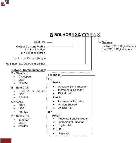
The part number at the top gives the type designation as follows:
Notes: |
•This manual is the EtherCAT version – for CAN functionality see the CAN version of this manual. The part number of the Gold Solo Hornet (EtherCAT version) has an E, for example, G-SOLHOR10/100E whereas the CAN version has an S, for example G- SOLHOR10/100S.
•There are two models of the Gold Solo Hornet: connectors only (for currents of 10 A or less) and wires only (for currents of 15 A or more). On request, the wires model may be ordered for currents of 10 A or less.
Table of Contents |www.elmomc.com

Gold Solo Hornet Installation Guide (EtherCAT and CAN) |
Installation |
24 |
MAN-G-SOLHORIG-EC (Ver. 1.009) |
|
|
|
|
|
4.3.Connectors and Indicators
The Gold Solo Hornet has 3 connectors (connectors version).
4.3.1.Connector Types
Port |
No. Pins |
Type |
Function |
|
|
|
|
|
|
J1 |
6/12 |
Nicomatic CMM 220 |
Motor, Power, Port B, Hall Phases |
|
|
|
6 HP/12 P |
|
|
|
|
|
|
|
J2 |
30 |
Nicomatic CMM 220 |
I/O, Auxiliary Feedback |
|
|
|
2 x 15P |
|
|
|
|
|
|
|
J3 |
20 |
Nicomatic CMM 220 |
Communication |
|
|
|
2 x 10P |
|
|
|
|
|
|
Figure 2: Connector Locations
Table 2: Connector Types
Table of Contents |www.elmomc.com

Gold Solo Hornet Installation Guide (EtherCAT and CAN) |
Installation |
25 |
MAN-G-SOLHORIG-EC (Ver. 1.009) |
|
|
|
|
|
4.3.2.Pinouts
The pinouts in this section describe the function of each pin in the Gold Solo Hornet connectors that are listed in Table 2.
4.3.2.1.Power, Motor, Control and Port B Connector (J1)
J1 consists of a Power, Motor and Control connector (6 pins) and Port B connector (12 pins), see Section 4.7 for more details.
4.3.2.1.a Power, Motor, and Control Connector (J1)
See Section 4.7.1 for more details.
Pin |
Signal |
Function |
|
Cable |
|
|
|
|
|
|
|
|
|
|
|
|
|
P1 |
VP+ |
Positive Power Input |
|
|
|
Power |
|
|
|
|
|
|
|
|
|
|
|
P2 |
PR |
Power Return |
|
|
|
Power |
|
|
|
|
|
|
|
|
|
|
|
P3 |
PE |
Protective Erath |
|
|
|
Power |
|
|
|
|
|
|
|
|
|
|
|
|
|
|
AC Motor |
|
DC Motor |
|
||
P4 |
M1 |
Motor Phase |
Motor |
|
N/C |
|
||
|
|
|
|
|
|
|
||
P5 |
M2 |
Motor Phase |
Motor |
|
Motor |
|
||
|
|
|
|
|
|
|
||
P6 |
M3 |
Motor Phase |
Motor |
|
Motor |
|
||
|
|
|
|
|
|
|
|
|
Pin Positions
Table 3: Power, Motor, and Control Connections
Table of Contents |www.elmomc.com

Gold Solo Hornet Installation Guide (EtherCAT and CAN) |
Installation |
26 |
MAN-G-SOLHORIG-EC (Ver. 1.009) |
|
|
|
|
|
4.3.2.1.b Port B Connector (J1)
See Section 4.7.1 for for more details.
|
|
Incremental Encoder |
|
|
Absolute Serial Encoder |
|
||
|
|
|
|
|
||||
|
|
|
|
|
|
|
|
|
Pin (J1) |
|
Signal |
Function |
|
|
Signal |
Function |
|
1 |
+5V |
Encoder +5V Supply |
+5V |
Encoder +5V Supply |
||||
|
|
|
|
|
|
|||
2 |
COMRET |
Supply Return |
|
SUPRET |
Supply Return |
|||
|
|
|
|
|
|
|
||
3 |
|
PORTB_ENC_A+/SIN+ |
Channel A+/Sine+ |
|
SIN+ |
Sine+ |
||
|
|
|
|
|
|
|||
4 |
|
PORTB_ENC_A-/SIN- |
Channel A -/Sine- |
SIN- |
Sine- |
|||
|
|
|
|
|
|
|
||
5 |
|
PORTB_ENC_B+/COS+ |
Channel B+/Cosine+ |
|
COS+ |
Cosine+ |
||
|
|
|
|
|
|
|||
6 |
|
PORTB_ENC_B-/COS- |
Channel B-/Cosine- |
COS- |
Cosine- |
|||
|
|
|
|
|
|
|||
7 |
|
PORTB_ENC_INDEX+/ |
Channel_Index+/ |
RESOLVER_OUT+ |
Vref f=1/TS, 50 mA |
|||
|
|
ANALOG_INDEX+ |
Analog_Index+ |
|
|
Max. |
||
|
|
|
|
|
|
|||
8 |
|
PORTB_ENC_INDEX-/ |
Channel_Index- / |
RESOLVER_OUT- |
Vref Complement |
|||
|
|
ANALOG_INDEX- |
Analog_Index- |
|
|
f= 1/TS, 50 mA |
||
|
|
|
|
|
|
|
Maximum |
|
|
|
|
|
|
|
|||
9 |
HA |
Hall Sensor A |
|
HA |
Hall Sensor A |
|||
|
|
|
|
|
|
|||
10 |
HB |
Hall Sensor B |
|
HB |
Hall Sensor B |
|||
|
|
|
|
|
|
|||
11 |
HC |
Hall Sensor C |
|
HC |
Hall Sensor C |
|||
|
|
|
|
|
|
|||
12 |
PE |
Protective Earth |
|
PE |
Protective Earth |
|||
|
|
|
|
|
|
|
|
|
Pin Positions
Table 4: Port B Pin Assignments
Table of Contents |www.elmomc.com

Gold Solo Hornet Installation Guide (EtherCAT and CAN) |
Installation |
27 |
MAN-G-SOLHORIG-EC (Ver. 1.009) |
|
|
|
|
|
4.3.2.2.Auxiliary Feedback and IO (J2)
See Section 4.9.1 for more details.
|
|
Incremental or Interpolated Analog |
|
Resolver |
|
|
|
|
|
|
|||
|
|
Encoder |
|
|
|
|
|
|
|
|
|
|
|
|
|
G-SOLHOR XXX/YYYYEX |
|
G-SOLHOR XXX/YYYYRX |
||
|
|
|
|
|
|
|
Pin (J2) |
Signal |
Function |
|
Signal |
Function |
|
4 |
|
PORTA_ENC_A+ |
Channel A + |
|
ABS_CLK+ |
Absolute Encoder |
|
|
|
|
|
|
Clock+ |
|
|
|
|
|
|
|
5 |
|
PORTA_ENC_A- |
Channel A - |
|
ABS_CLK- |
Absolute Encoder |
|
|
|
|
|
|
Clock- |
|
|
|
|
|
|
|
6 |
|
PORTA_ENC_B+ |
Channel B+ |
|
ABS_DATA+ |
Absolute Encoder |
|
|
|
|
|
|
Data+ |
|
|
|
|
|
|
|
7 |
|
PORTA_ENC_B- |
Channel B - |
|
ABS_DATA- |
Absolute Encoder |
|
|
|
|
|
|
Data- |
|
|
|
|
|
|
|
8 |
|
PORTA_ENC_INDEX+ |
Index+ |
|
RESERVED |
Reserved |
|
|
|
|
|
|
|
9 |
|
PORTA_ENC_INDEX- |
Index- |
RESERVED |
Reserved |
|
|
|
|
|
|
|
|
10 |
|
PORTC_ENCO_A- |
Buffered Channel A Complement Output |
|||
|
|
|
|
|
||
11 |
|
PORTC_ENCO_A+ |
Buffered Channel A Output |
|
||
|
|
|
|
|||
12 |
|
PORTC_ENCO_B- |
Buffered Channel B Complement Output |
|||
|
|
|
|
|
||
13 |
|
PORTC_ENCO_B+ |
Buffered Channel B Output |
|
||
|
|
|
|
|
||
14 |
|
PORTC_ENCO_INDEX- |
Buffered INDEX Complement Output |
|
||
|
|
|
|
|
||
15 |
|
PORTC_ENCO_INDEX+ |
Buffered INDEX Output |
|
||
|
|
|
|
|
|
|
16 |
|
COMRET |
Common Return |
|
|
|
|
|
|
|
|
||
17 |
|
ANALOG1- |
Analog Input Complement |
|
||
|
|
|
|
|
|
|
18 |
|
ANALOG1+ |
Analog Input |
|
|
|
|
|
|
|
|
|
|
19 |
|
ANLRET |
Analog Return |
|
|
|
|
|
|
|
|
||
20 |
|
INRET |
Programmable Input 1 – 6 Return |
|
||
|
|
|
|
|
||
21 |
|
IN1 |
Programmable Input 1 (High Speed) |
|
||
|
|
|
|
|
||
22 |
|
IN2 |
Programmable Input 2 (High Speed) |
|
||
|
|
|
|
|
||
23 |
|
IN3 |
Programmable Input 3 (High Speed) |
|
||
|
|
|
|
|
||
24 |
|
IN4 |
Programmable Input 4 |
|
||
|
|
|
|
|
|
|
|
STO1 |
ST01 Input (Default 24 V) |
|
|||
|
|
|
||||
|
|
|
|
|
|
|
Table of Contents |www.elmomc.com
Loading...