

Page 1
VIO Starter Addendum Elmo Motion Control
VIO - STARTER
Addendum to the VIO Operating Manual
Revision 1/07
Introduction
This addendum is intended for the use of the design engineer who uses a VIO amplifier
with a VIO-STARTER evaluation and interface board. This document should be
regarded as an extension to the “VIO Operating Manual”, describing ONLY the pins
and functions (of the VIO amplifier) that are either different or slightly modified from
the description in the “VIO Operating Manual”. The chapters in this document are
sequenced in correlation to the chapters in the “VIO Operating Manual” that cover the
same information.
Rev. 1/07
Page 2

VIO Starter Addendum Elmo Motion Control
Description
Refer to section 2 in the “VIO Operating Manual”
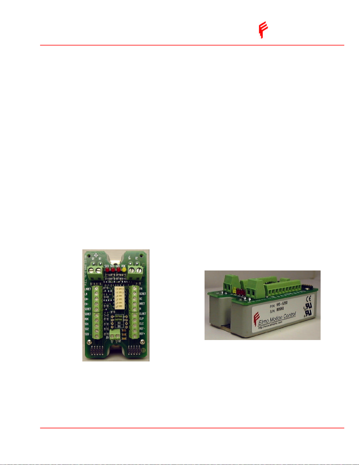
The VIO-STARTER is an add-on interconnection board for the VIO servo amplifier
that plugs on top of the amplifier. The purpose of this board is the translation of the VIO
solder type pins into screw type terminals thus enabling easy connectivity for evaluation
and low quantity applications.
One to one relationship between board terminals and the pins of the VIO is kept.
Standard Features
Refer to section 2.1 in the “VIO Operating Manual”
q Four LEDs allow convenient diagnostics of the VIO status outputs
q The dedicated digital inputs can be activated by DIP switches
q Scaling resistors are provided for adjusting the current limits and the command
reference
Type designation
VIO-Starter
Pins functions
There is a new terminal strip – J4 with the following functions:
Terminal Function
+VCC Positive supply voltage for the LED’s
VCCRET Return for the LED supply voltage
Current Command Scaling Resistors (R1 & R2)
Refer to section 3.1 in the “VIO Operating Manual”
The user can change the default scale of the differential input (±3.75V) by calculating
and inserting R1 & R2 into the designated solderless terminals. The value of theses
resistors is given by:
R1=R2=5.33*Vcref-20 [KΩ]
Vcref is the desired maximum reference voltage.
If for example, the new desired scale is ±10V, all that is required is to change the
default resistors (0 ohms) to 33Kohm.
External Current Limit – Continuous (ECLC)
Refer to section 3.4 in the “VIO Operating Manual”
A solderless terminal is available for Reclc. It is designated as R3.
External Current Limit – Peak (ECLP)
Refer to section 3.5 in the “VIO Operating Manual”
A solderless terminal is available for Reclp. It is designated as R4.
Rev. 1/07
Page 3

VIO Starter Addendum Elmo Motion Control
DIP – Switches
Switch Function ON OFF
S1 CGC CGC – ON (see section 3.3 in “VIO
Operating Manual)
S2 N/C
S3 CFM CFM – ON (see section 3.2 in “VIO
Operating Manual)
S4 LM LM – ON (see section 3.6 in “VIO
Operating Manual)
S5 EN+ Setting S5 to ON applies +VCC voltage to
EN+ pin (If +VCC is applied to J4). Setting
both S5 & S6 will enable the amplifier
without an external signal.
S6
EN−
Setting S6 to ON connects VCCRET to EN-
pin.
Supply Voltage (+VCC & VCCRET)
In order to operate the diagnostics LEDs and/or use the enable (EN) feature, an external
voltage must be applied to +VCC & VCCRET terminals at J3. The DC supply
requirements are as follows:
Min. input voltage 5VDC
Max. input voltage 15VDC
Max. input current 13 mA
CGC - OFF
CFM - OFF
LM – OFF
No voltage is
applied to EN+
No voltage is
applied to EN−
LED Indications
Refer to section 5 in the “VIO Operating Manual”
Function Latch option AOK SO1 SO2 SO3
Amplifier OK (AOK) N/A ON OFF OFF OFF
External disable No ON ON OFF ON
Current limit No ON OFF OFF ON
Short Yes OFF ON OFF ON
Over temperature Yes OFF OFF ON ON
Internal supplies
protection
Under voltage No OFF ON OFF OFF
Over voltage No OFF OFF ON OFF
Shunt request No ON OFF ON OFF
Power Up Reset No OFF OFF OFF OFF
Note: LEDs will light only if voltage is applied to +VCC and VCCRET.
Rev. 1/07
No OFF ON ON OFF
 Loading...