

Page 1

This PDF contains two manuals:
1. The SimplIQ for Steppers Command Reference Manual
2. The SimplIQ for Steppers Application Note
.
There are hyperlinks from the Command Reference to the
Application Note.
.
Page 2
SimplIQ for Steppers
SimplIQ for Steppers
SimplIQ for SteppersSimplIQ for Steppers
Command Reference
Manual
Ver. 1.1 - June 2009
Page 3

SimplIQ for Steppers Command Reference Manual
MAN-STECR (Ver. 1.1)
Important Notice
This guide is delivered subject to the following conditions and restrictions:
This guide contains proprietary information belonging to Elmo Motion Control Ltd.
Such information is supplied solely for the purpose of assisting users of
Steppers servo drives.
The text and graphics included in this manual are for the purpose of illustration and
reference only. The specifications on which they are based are subject to change
without notice.
Information in this document is subject to change without notice.
Doc. No. MAN-STECR
Copyright 2009
Elmo Motion Control
All rights reserved
Revision History
SimplIQ for
Ver. 1.1 June 2009 Updates
Ver. 1.0 Feb 2008 First revision.
Elmo Motion Control Ltd.
64 Gisin St., P.O. Box 463
Petach Tikva 49103
Israel
Tel: +972 (3) 929-2300
Fax: +972 (3) 929-2322
info-il@elmomc.com
Elmo Motion Control Inc.
42 Technology Way
Nashua, NH 03060
USA
Tel: +1 (603) 821-9979
Fax: +1 (603) 821-9943
info-us@elmomc.com
Elmo Motion Control GmbH
Steinkirchring 1
D-78056, Villingen-Schwenningen
Germany
Tel: +49 (0) 7720-85 77 60
Fax: +49 (0) 7720-85 77 70
info-de@elmomc.com
www.elmomc.com
Page 4

SimplIQ for Steppers Command Reference Manual Contents
MAN-STECR (Ver. 1.1)
Contents
Chapter 1: Introduction..............................................................................................................1
1.1. Command Specification....................................................................................................2
1.2. Scope...................................................................................................................................2
1.3. Reserved Commands........................................................................................................ 3
Chapter 2: Functional Listing ...................................................................................................5
2.1 Motion Commands................................................................................................................5
2.2 I/O Commands......................................................................................................................6
2.3 Status Commands.................................................................................................................. 6
i
2.4 Feedback Commands............................................................................................................6
2.5 Configuration Commands.................................................................................................... 7
2.6 Communication Commands.................................................................................................8
2.7 Control Filter Commands.....................................................................................................8
2.8 Protection Commands...........................................................................................................8
2.9 Data Recording Commands..................................................................................................9
2.10 User Program Commands ..................................................................................................9
2.11 General Commands...........................................................................................................10
Chapter 3: Alphabetical Listing..............................................................................................11
Limit Ranges ..............................................................................................................................13
AB[N] – Absolute Encoder Setting Parameters...................................................................... 14
AC - Acceleration ...................................................................................................................... 15
AG[N] - Analog Gains Array ................................................................................................... 16
AN[N] – Analog input array.................................................................................................... 18
AR[N] – Active Route array .....................................................................................................19
AS[N] - Analog Input Offsets Array........................................................................................ 20
BG - Begin Motion..................................................................................................................... 21
BH - Get a Single Recorded Signal as Hexadecimal ..............................................................22
BP[N] - Brake Parameter........................................................................................................... 23
BT - Begin Motion at Defined Time......................................................................................... 24
Page 5

SimplIQ for Steppers Command Reference Manual Contents
MAN-STECR (Ver. 1.1)
BV - Maximum Motor DC Voltage.......................................................................................... 25
CA[N] - Commutation Array................................................................................................... 26
CC - Compiled Program Ready ............................................................................................... 32
CD - CPU Dump........................................................................................................................ 33
CL[N] - Current Continuous Limitations and Motor Stuck Protection Parameters..........35
CP - Clear Program ...................................................................................................................37
DC - Deceleration ......................................................................................................................38
DD - CAN Controller Status.....................................................................................................39
DF/DT - Download Firmware................................................................................................. 40
DL - Download Program .......................................................................................................... 41
DV[N] - Reference Desired Value............................................................................................ 42
ii
EC - Error Code..........................................................................................................................44
EF[N] - Encoder Filter Frequency ............................................................................................57
EM[N] - ECAM Parameters......................................................................................................58
EO - Echo Mode......................................................................................................................... 60
ER[N] - Maximum Tracking Error...........................................................................................61
ET[N] - Entries for ECAM Table..............................................................................................62
FF[N] - Feed Forward................................................................................................................63
FR[N] - Follower Ratio.............................................................................................................. 64
GS[N] - Gain Scheduling ..........................................................................................................65
HL[N] - Over-speed Limit and Position Range Limit ...........................................................66
HM[N] - Homing, Capture and Flag....................................................................................... 67
HP - Halt Program Execution...................................................................................................70
HT[N] – Holding torque........................................................................................................... 71
HX - Hexadecimal Mode ..........................................................................................................72
HY[N] - Auxiliary Homing, Capture and Flag.......................................................................73
IB[N] - Input Bits Array ............................................................................................................ 76
ID, IQ - Read Active Current and Reactive Current.............................................................. 77
IF[N] - Digital Input Filter........................................................................................................ 78
IL[N] - Input Logic ....................................................................................................................79
IP - Input Port ............................................................................................................................86
Page 6

SimplIQ for Steppers Command Reference Manual Contents
MAN-STECR (Ver. 1.1)
JV- Jogging Velocity .................................................................................................................. 88
KG[N] - Gain Scheduled Controller Parameters....................................................................89
KI[N], KP[N] - PI Parameters................................................................................................... 90
KL - Kill Motion and Program .................................................................................................91
KV[N] - High-order Controller Filter Parameters.................................................................. 92
LC - Current Limit Flag ............................................................................................................94
LD - Load Parameters from Flash............................................................................................95
LL[N] - Low Feedback Limit.................................................................................................... 97
LP[N] - List Properties .............................................................................................................. 98
LS - List User Program..............................................................................................................99
MC - Maximum Peak Driver Current....................................................................................100
iii
MF - Motor Failure .................................................................................................................. 101
MI - Mask Interrupt................................................................................................................. 105
MO - Motor Enable/Disable...................................................................................................107
MP[N] - Motion (PT/PVT) Parameters................................................................................. 109
MS – Motion Status ................................................................................................................. 111
OB[N] - Output Bits Array .....................................................................................................112
OC[N] – Output Compare...................................................................................................... 114
OL[N] - Output Logic..............................................................................................................117
OP - Output Port......................................................................................................................119
PA - Absolute Position............................................................................................................120
PE - Position Error................................................................................................................... 122
PK - Peek Memory................................................................................................................... 123
PF[N] – Floating point parameters ........................................................................................ 124
PL[N] - Peak Duration and Limit........................................................................................... 127
PM - Profiler Mode.................................................................................................................. 129
PN[N] –Integer parameters ....................................................................................................130
PP[N] - Protocol Parameters...................................................................................................132
PR - Relative Position.............................................................................................................. 134
PS - Program Status................................................................................................................. 135
PT - Position Time Command................................................................................................ 136
Page 7

SimplIQ for Steppers Command Reference Manual Contents
MAN-STECR (Ver. 1.1)
PV - Position Velocity Time Command.................................................................................137
PW[N] - PWM Signal Parameters.......................................................................................... 138
PX - Main Position................................................................................................................... 139
PY - Auxiliary Position ...........................................................................................................140
QP[N], QT[N], QV[N] - Position, Time, Velocity................................................................. 141
RC - Define Recorded Variables.............................................................................................142
RG - Recorder Gap ..................................................................................................................143
RL - Record Length..................................................................................................................144
RM - Reference Mode.............................................................................................................. 145
RP[N] - Recorder Parameters ................................................................................................. 146
RR - Activate Recorder/Get Recorder Status....................................................................... 148
iv
RS - Soft Reset.......................................................................................................................... 150
RV[N] - Recorded Variables................................................................................................... 151
SD - Stop Deceleration ............................................................................................................ 152
SI - Synchronize Motion Processor Tables............................................................................ 153
SF - Smooth Factor...................................................................................................................154
SN - Serial Number .................................................................................................................155
SP - Speed for PTP Mode........................................................................................................ 156
SR - Status Register..................................................................................................................157
ST - Stop Motion...................................................................................................................... 159
SV - Save Parameters to Flash................................................................................................ 160
TC - Torque Command ...........................................................................................................161
TI[N] – Temperature indications array ................................................................................. 162
TM - System Time.................................................................................................................... 163
TR - Target Radius................................................................................................................... 164
TT[N] – Motion Processor Sampling Time ...........................................................................165
TV[N] – Motion Processor Tables.......................................................................................... 166
TW[N] – Wizard Command ...................................................................................................167
UF[N] – User Float Array ....................................................................................................... 168
UI[N] – User Integer................................................................................................................ 169
UM - Unit Mode.......................................................................................................................170
Page 8

SimplIQ for Steppers Command Reference Manual Contents
MAN-STECR (Ver. 1.1)
VC[N]- Voltage Command..................................................................................................... 172
VE - Velocity Error .................................................................................................................. 173
VH[N], VL[N] - High and Low Reference Limit.................................................................. 174
VR - Firmware Version ...........................................................................................................175
VX, VY - Velocity of Main and Auxiliary Feedback ............................................................ 176
WI[N] - Miscellaneous Reports, Integer................................................................................ 177
WS[N] - Miscellaneous Reports ............................................................................................. 179
XA[N] - Extra Parameters.......................................................................................................182
XC, XQ - Execute or Continue Program................................................................................ 183
XM[N] - X Modulo ..................................................................................................................184
YA[N] - Auxiliary Position Sensor Parameters....................................................................186
v
YM[N] - Y Modulo ..................................................................................................................188
ZX[N] - User Program and Auto-tuning Temporary Storage............................................. 190
Page 9
SimplIQ for Steppers Command Reference Manual Introduction
MAN-STECR (Ver. 1.1)
Chapter 1: Introduction
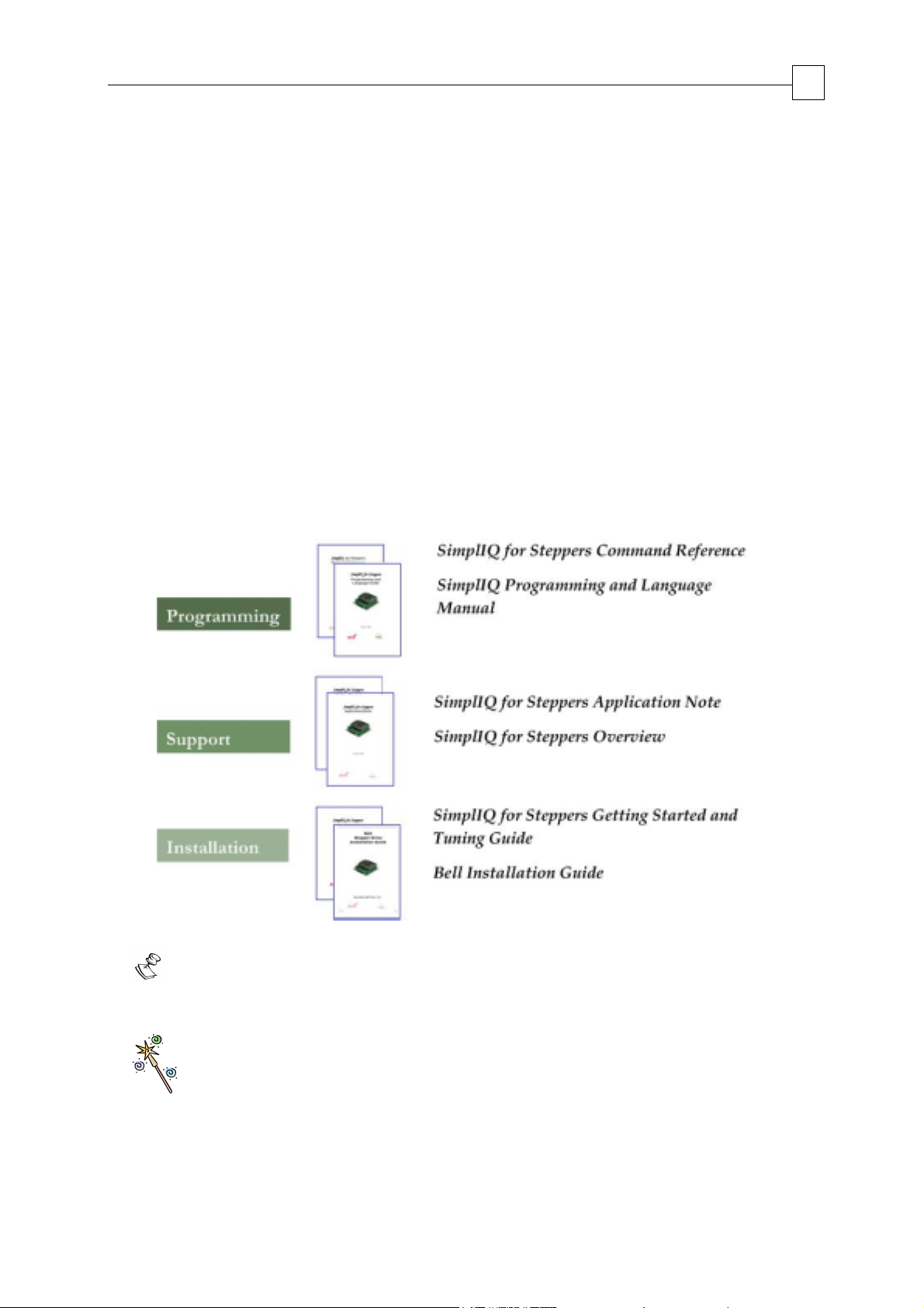
This manual describes, in detail, each software command used to manipulate the SimplIQ
for Steppers line of digital servo drives. It is an integral part of the SimplIQ for Steppers
documentation set, which includes:
The Bell Stepper Drive Installation Guide, which provides full instructions for
installing a drive.
The Composer User Manual, which includes explanations of all the software tools that
are a part of Elmo’s Composer software environment.
The SimplIQ for Steppers has been derived from Elmo's SimplIQ interface. Most of the
commands and explanations are identical. There are, however, some changes, following
the introduction of stepper capabilities. We have tried to keep the changes minimal.
1
The following diagram illustrates the available
SimplIQ for Steppers documentation.
Note:
This command reference does not describe commands that are only
intended for service vendor-supplied tuning and setup tools.
Commands that are normally used by service vendor-supplied tuning and setup
tools, but in some situations may be used by advanced users, are marked with this
"Wizard's wand" symbol.
Page 10

SimplIQ for Steppers Command Reference Manual Introduction
MAN-STECR (Ver. 1.1)
1.1. Command Specification
Commands for SimplIQ for Steppers drives may be specified from the following
sources:
User program A program loaded to the servo drive via one of the
communication options. After program execution begins, the
program is managed by the drive.
RS-232 Serial, point-to-point, short-range communication. Although this
method is rather slow, RS-232 is very easy to use and the
requirements are minimal: a standard PC with a serial port and
ASCII terminal software.
CANopen Serial, multi-drop, medium speed and medium-range
communication. This type of communication requires specialpurpose host hardware and software.
2
This manual describes the
SimplIQ for Steppers commands that can be specified from
each of these sources. Most of the commands are equally available for all three
sources. Certain commands, however, are limited in scope according to the type of
program or communication.
All the commands are available to CAN communication in text form through the OS
service objects 0x1023 and 0x1024. In addition, the numerical set/get commands are
available to CAN users in short PDO form, called the “binary interpreter.” The binary
and the OS SCAN interpreters are described fully in the CANopen Implementation Guide.
CANopen may also be used to manipulate the drive using the object dictionary (OD)
method, which is the native CAN method. This manual does not cover OD manipulations
with CANopen; refer to the “Object Dictionary” section of the CANopen Implementation
Guide for full explanations.
The
SimplIQ for Steppers drive responds to many privileged commands — such as
those used by the Composer setup wizard — that are not documented in this manual.
1.2. Scope
This manual includes the complete list of commands used by SimplIQ for Steppers servo
drives.
It specifies how to use each command, along with added remarks and examples.
The first part of this manual describes the communicated commands and their response.
The second part describes the user program and its control logic.
The commands are presented in two ways:
A task-related listing
Alphabetically
Page 11

SimplIQ for Steppers Command Reference Manual Introduction
MAN-STECR (Ver. 1.1)
In the task-related reference, the commands are sorted into groups of related commands.
Each group is presented in a table listing the commands with basic descriptions. The
alphabetical command listing provides a detailed explanation of each command, with
examples and references to the
SimplIQ for Steppers Application Note when necessary.
This Command Reference Manual covers in addition the following topics:
User program keywords, used for writing user programs. These, as well as other
issues of developing, running and debugging user programs, are covered in the
SimplIQ for Steppers Application Note.
3
Interpreter functions and operators. The
SimplIQ for Steppers interpreter allows
complex arithmetic expressions and supports many arithmetic, trigonometric and
logical operators. The syntax for interpreter commands is explained in the
“Interpreter Language” chapter of the
SimplIQ for Steppers Application Note.
1.3. Reserved Commands
SimplIQ for Steppers recognizes some reserved commands. The reserved commands
serve the setup and tuning support software, or are intended for future implementation.
Some mnemonics are no longer used but they remain so that users can run legacy
applications written for the SimplIQ series.
The reserved commands appear in the following table:
Command mnemonic Used for
AB[N] Absolute encoder setting parameters
AR[N] Active recording session - Special Wizard commands
BH Get a sample signal as hexadecimal
CC Compile program
DF Download firmware
DL Receive a program downloaded from the host computer to
Metronome. Can be used only in Composer software.
HP Halt program execution
LP[N] List parameters
LS List program
PK Peek memory
RC Variables to record (two variables at each recording
sequence)
RG Recording gap, in samples. Gap between consecutive data
recordings.
RL Record length
RP[N] Recorder parameters
RR Recording on/off
RV[N] Recorded variables
Page 12

SimplIQ for Steppers Command Reference Manual Introduction
MAN-STECR (Ver. 1.1)
Command mnemonic Used for
SI Synchronize correction tables
TS Obsolete – see TT[N]
TV[N] Correction tables data
TW[N] Wizard command
VC[N] Phase voltage command - Special wizard commands
WI[N] Metronome data, mainly for use by the Composer.
XA[N] Obsolete – see PF[N]
XC Continue program execution from current pointer, optionally
until a given breakpoint
XP[N] Obsolete – see PF[N], PN[N])
ZP[N] Frequency response identification
4
ZX[N]
User program and auto-tuning temporary storage
Page 13

SimplIQ for Steppers Command Reference Manual Functional Listing
MAN-STECR (Ver. 1.1)
Chapter 2: Functional Listing
This chapter summarizes the SimplIQ for Steppers commands according to the following
functional groups:
Motion Motion parameters, type and status. Begin/stop motion.
I/O Set outputs and report inputs.
Status Report Metronome status.
Feedback Support the multi-featured feedback interfaces.
Configuration Servo drive and motor types, and limitations.
Communication Communication type and parameters.
Control filters Digital, torque, speed and position filters.
Protections Failure and protection definitions.
5
Data recording Recording of internal Metronome variables for analysis.
User programs Application programming
General Miscellaneous commands.
Commands associated with more than one group are listed more than once.
2.1 Motion Commands
Command Description Page
2
AC Acceleration, in counts per second
BG Begin motion 21
BT Begin motion at defined time 24
DC Deceleration, in counts per second2 38
HT[N] Stepper mode holding torque 70
IL[N] Input logic, defining how dedicated inputs behave 79
JV Speed of jogging motion, in counts per second2 88
MO Motor on/off 106
14
PA Absolute position reference for point-to-point motion 120
PR Relative position reference for point-to-point motion 134
SD Stop deceleration 152
SF Smooth factor for motion command 154
SP Speed for point-to-point motion 156
ST Stop motion using deceleration value 159
TC Torque command 161
Page 14

SimplIQ for Steppers Command Reference Manual Functional Listing
MAN-STECR (Ver. 1.1)
2.2 I/O Commands
Command Description Page
AN[N] Read analog inputs 18
IB[N] Bit-wise digital input 76
IF[N] Digital input filter 78
IP Read all digital inputs 86
OB[N] Bit-wise digital output 112
OC[N] Output Compare 114
OL[N] Output Logic 117
OP Set all digital outputs 119
6
2.3 Status Commands
Command Description Page
BV Maximum motor DC voltage 25
DD CAN controller status 39
DV[N] Reference desired value 42
EC Error code: get code for last interpreter error 44
LC Current limitation: report status of current limitation
algorithm
MF Motor fault: code for last motor-disable cause 101
MS Motion status reporting 111
PK Peak memory 123
SN Serial number 155
SR Numerical, bit-coded Metronome status 157
TI[N] Temperature indications array 162
VR Software (firmware) version 175
94
2.4 Feedback Commands
Command Description Page
AB[N] Absolute encoder setting parameters 14
ID Read active current 77
Page 15

SimplIQ for Steppers Command Reference Manual Functional Listing
MAN-STECR (Ver. 1.1)
7
Command Description Page
IQ Read reactive current 77
PE Position error 122
PX Main encoder position, in counts 139
PY Auxiliary position 140
VE Velocity error, in counts per second2 173
VX Main encoder velocity, in counts per second2 176
VY Velocity of auxiliary feedback 176
YA[N] Auxiliary position sensor parameters 186
2.5 Configuration Commands
Command Description Page
AG[N] Analog gains array 16
AS[N] Analog input offsets array 20
BP[N] Brake parameter 23
CA[N] Commutation parameters array 26
CL[N] Current continuous limitations array 35
EF[N] Encoder filter frequency 57
EM[N] ECAM parameters 58
ET[N] Entries for ECAM table 62
FF[N] Feed forward 63
FR[N] Follower ratio 64
HM[N] Homing and capture mode 67
HY[N] Auxiliary home and capture mode 73
MC Define maximum peak current of servo drive, in Amperes 99
MP[N] Motion (PT/PVT) parameters 109
PL[N] Peak duration and limit 127
PM Profiler mode 129
PT Position time command 136
PV Position velocity time command 137
PW[N] PWM signal parameters 138
QP[N] Position 141
Page 16

SimplIQ for Steppers Command Reference Manual Functional Listing
MAN-STECR (Ver. 1.1)
Command Description Page
QT[N] Time 141
QV[N] Velocity 141
8
RM Reference mode: external (analog) referencing
145
enabled/disabled
TR Target radius 164
UM Unit mode: stepper, torque control, speed control position
170
control or dual loop
VH[N] High reference limit 174
VL[N] Low reference limit 174
XM[N] X Modulo 184
YM[N] Y Modulo 188
2.6 Communication Commands
Command Description Page
PP[N] Define the parameters of the CAN or RS-232
communication
132
2.7 Control Filter Commands
Command Description Page
GS[N] Gain scheduling 65
KG[N] Gain scheduled controller parameters 89
KI[N] PID integral terms array 90
KP[N] PID proportional terms array 90
KV[N] Advanced filter for speed loop 92
XA[N] Extra parameters (more) 182
2.8 Protection Commands
Command Description Page
ER[N] Maximum tracking errors 61
HL[N] Over-speed limit and position range limit 66
LL[N] Low actual feedback limit 97
Page 17

SimplIQ for Steppers Command Reference Manual Functional Listing
MAN-STECR (Ver. 1.1)
PL[N] Peak current, in amperes; and peak duration, in seconds 127
2.9 Data Recording Commands
Command Description Page
BH Get a sample signal as hexadecimal 22
9
RC Variables to record (two variables at each recording
142
sequence)
RG Recording gap, in samples. Gap between consecutive data
143
recordings.
RL Record length 144
RP[N] Recorder parameters 146
RR Recording on/off 148
RV[N] Recorded variables 151
YM[N] Auxiliary sensor modulo count 188
2.10 User Program Commands
Command Description Page
CC Compile program 32
CP Clear application program 37
DL Receive a program downloaded from host computer to
Metronome. Can be used only in Composer software.
41
HP Halt program execution 70
KL Kill motion and stop program (like HP) 91
LP[N] List parameters 98
LS List program 99
MI Mask interrupt 105
PS Program status 135
XC Continue program execution from current pointer,
183
optionally until a given breakpoint
XQ Execute program, optionally starting at a given label and
183
until a given breakpoint
Page 18

SimplIQ for Steppers Command Reference Manual Functional Listing
MAN-STECR (Ver. 1.1)
2.11 General Commands
Command Description Page
AR[N] Active recording session - Special Wizard commands 19
CD CPU dump: CPU and database exception summary 33
DF Download firmware 40
EO Echo mode 60
HX Select hexadecimal or decimal mode 72
LD Load parameters form flash memory 95
10
PN[N] Integer parameters
RS Reset Metronome to a pre-defined state and parameter
130
150
value
SI Synchronize correction tables 153
SV Save parameters to flash memory 160
TM System time 163
TT[N] Sampling time of motion controller 165
TV[N] Correction tables data 166
TW[N] Wizard command 167
UF[N] User float array 168
UI[N] User integer 169
VC[N] Phase voltage command - Special wizard commands 172
WI[N] Metronome data, mainly for use by Composer 177
WS[N] Metronome data, mainly for use by Composer 179
ZX[N] User program and auto-tuning temporary storage 190
Page 19

SimplIQ for Steppers Command Reference Manual Alphabetical Listing
MAN-STECR (Ver. 1.1)
Chapter 3: Alphabetical Listing
This chapter lists all the commands in alphabetical order, along with detailed
definitions and examples of each command.
The description of each command includes the following items:
Purpose: The operation or task of the command
Attributes: The characteristics of the command
Type: One of the following:
A command: An instruction to do something. For example, the BG
(Begin Motion) command starts a new motion profile.
A parameter: A data item that may be used later. For example, the AC
(Acceleration) parameter is required for calculating subsequent motions.
11
A status report: Get a value, such as the motor speed, a digital input
or the reason for the last motor failure.
The parameters and certain commands have numerical values, as follows:
Integer: A 32-bit long integer
Real: A 32-bit floating point number (IEEE style)
String: A set of printable ASCII characters
Integer variables may have the following attributes:
Bit field: The integer should be understood not as a number but rather as a
combination of binary fields. For example, the IP (Digital Input) command reads
many On/Off switches to the same integer, allocating one bit for each.
Option: A selector that may accept one of several options. For example, the
motor direction may be set to forward or reverse, symbolized by the numbers 0
and 1 respectively.
Source: Defines the “agents” that may use the command, as follows:
RS-232 communication
CANopen communication
User program
The command access rights are not equal for all sources. For example,
CANopen binary interpreter cannot use the string commands listed in
this manual. Another example is the XQ (Execute Program) command
that, of course, cannot be performed from within a program.
Page 20

SimplIQ for Steppers Command Reference Manual Alphabetical Listing
MAN-STECR (Ver. 1.1)
Restrictions: The use of certain commands is illegal in certain contexts. The
reasons for this may be:
Safety: For example, it is not safe to change the direction of the feedback while
the motor is running.
Relevance: For example, a torque command cannot be specified in speed control
mode (UM=2); in speed mode, the drive automatically sets the torque.
Consistency: A parameter may be inconsistent with the specification of other
parameters. For example, in point-to-point mode, the position absolute value
(PA) may be no higher than the maximum allowed position reference (VH[3]).
Default values: Default value and storage type.
Volatile variables are reset to their defaults with each power on.
Non-volatile variables can be stored using the SV command.
Stored non-volatile values are read from storage upon power on
and can be reset to their defaults using the RS command.
12
Range: Range definition: For example, the position command may be
specified in the range [-1,073,741,824…-1,073,741,823]
Unit mode (UM): Defines the function of the drive. The unit modes are:
UM=1 Torque control
UM=2 Speed control
UM=3 Micro-stepping
UM=4 Dual-feedback position control
UM=5 Single-feedback position control
Activation: Specifies when the entered parameter value should be used.
Activation may be:
Immediate As soon as the command is processed
Triggered By another command
For example, the AC (acceleration) parameter should only affect
the next motion, triggered by the BG command.
Examples: Simple examples of the command usage. All examples are given in
RS-232 syntax.
See also: Related commands
Reference chapter Chapter or section that contains relevant details pertinent to the
in the SimplIQ for command.
Page 21

SimplIQ for Steppers Command Reference Manual Alphabetical Listing
MAN-STECR (Ver. 1.1)
Limit Ranges
The following table lists the value ranges for defining the limits of the system.
Subject Values
Position counter ranges Main position counter is subjected to a modulo
counting with the following ranges:
XM[1]: Lowest value
XM[2]: Highest value
Range: [-5x10
Auxiliary position counter is limited to:
YM[1]: Lowest value
YM[2]: Highest value
Range: [-5x10
8
…5x10⁸] counts
8
…5x10⁸] counts
13
Velocity range Range for Quadrature Encoder:
[-40,000,000…40,000,000] counts/sec
Range for other feedbacks:
[-80,000,000…80,000,000] counts/sec
EF[1]: Filter for main velocity sensor
EF[2]: Filter for auxiliary velocity sensor
Acceleration/Deceleration ranges Range: [100…1,000,000,000]
Stop deceleration range Range: [100…1,000,000,000]
Torque limits Range of torque command is subjected to the
following limits:
CL[1], PL[1]
Range: [-MC…MC]
Note:
The multiplication of the PWM frequency
reduces the torque limit.
Table 3-1: Limit Ranges
Page 22

SimplIQ for Steppers Command Reference Manual Alphabetical Listing
MAN-STECR (Ver. 1.1)
AB[N] – Absolute Encoder Setting Parame te rs
Purpose:
This command is reserved for future hardware that will support an absolute encoder.
14
Page 23

SimplIQ for Steppers Command Reference Manual Alphabetical Listing
MAN-STECR (Ver. 1.1)
AC - Acceleration
Purpose:
Defines the maximum acceleration in counts/second
mode (UM=2) and position control modes (UM=3, 4, 5) in PTP (PA, PR) and jogging
(JV) reference modes.
The AC parameter does not affect the present motion. It is used for planning the next
motion, which is initiated by a BG command.
If AC is smaller than SD, the maximum possible acceleration will be limited to
SD and the value of AC will be ineffective.
Attributes: Type: Parameters, Integer
Source: Program, RS-232, CANopen
Restrictions: None
Default values: 20,000,000 (RS), Non-volatile
Range: Acceleration range
Unit modes: UM=2, 3, 4, 5
Activation: BG
SimplIQ: Similar
2
. This parameter is used in speed
15
Typical applications:
1. Define acceleration limits for the motion (UM=2)
2. Plan a profiled motion (UM=3, 4, 5)
See also:
DC
, SP, SV, PA, PR, BG
Application notes:
The Position Reference Generator
The speed software command
Page 24

SimplIQ for Steppers Command Reference Manual Alphabetical Listing
MAN-STECR (Ver. 1.1)
AG[N] - Analog Gains Array
Purpose:
Sets the gains for preconditioning analog signals, when RM = 1:
AG[1] sets the gain of analog input #1 when used as a torque command (UM=1, 3).
AG[2] sets the gain of analog input #1 when used as a speed command (UM=2).
When RM = 0, the AG[N] parameters are ignored.
The meaning of the analog gains depends on the unit mode, as shown in the following
table.
Value Description Units
16
UM=1, 3 One volt at the analog reference input
Ampere/volt
command controls the motor phase current of
AG[1] amperes.
UM=2 One volt at the analog reference input
Count/second/volt
command controls a speed of AG[2]
counts/second.
Table 3-2: Analog Gains - Analog Input #1
Notes:
AG[1] defines motor phase amperes and not RMS amperes.
In stepper mode (UM=3), the two external inputs play different roles: The analog
input voltage sets the motor power while the follow pulse/direction or
quadrature input determines the position.
The polarity of the analog reference signal may be reversed by setting the sign of
the AG[N] parameter accordingly.
Attributes: Type: Parameter, Real
Source: Program, RS-232, CANopen
Restrictions: None
Default values: AG[1]=0.1
AG[2]=1
Non-volatile
Range: AG[1]: [-10000…10000]
AG[2]: [-20,000,000…20,000,000]
Index range: [1, 2]
Unit modes: All
SimplIQ: Similar, ranges changed
Activation: Immediate
See also:
AN[N]
, AS[N], UM, RM, VH[N], VL[N]
Page 25

SimplIQ for Steppers Command Reference Manual Alphabetical Listing
MAN-STECR (Ver. 1.1)
Application notes:
Speed reference generation
Open loop stepper control
17
Page 26

SimplIQ for Steppers Command Reference Manual Alphabetical Listing
MAN-STECR (Ver. 1.1)
AN[N] – Analog input array
Purpose:
AN[1] reports the analog input #1 value after offset correction (AS[1]), in volts.
AN[2] reports the analog input #2 value after offset correction (AS[2]) in volts,
for products that support a second analog input.
AN[3] … AN[5] – see table below.
AN[6] reports the DC line voltage value, in volts. Note that for AC products,
this value is after rectification. For example, with 1-phase 220 VAC supply,
expect AN[6]=√2x220=310 V. with 3-phase 380 VAC L-L supply, expect
AN[6]=√2x380=540 V.
AN[7] reports the duty cycle value of the PWM signal after offset correction in
fractional units.
18
Attributes: Type: Status report, Real
Source: Program, RS-232, CANopen
Restrictions: None
Unit modes: All
SimplIQ: Modified
AN[3..5] read motor phase currents, in Amperes. The meaning depends on the motor
type
2-phase (stepper)
AN[3] Phase A
AN[4] Phase B
AN[5] 0
Typical applications:
1. Reading external sensors that provide ±10 V.
2. Reading analog or PWM references for either velocity or current.
3. Reading phase currents and line voltage.
Notes:
See also:
AG[N]
, AS[N], PW[N]
Analog input #1 serves as reference input for analog torque or analog
velocity command while in auxiliary reference mode (RM=1).
Different
SimplIQ drives support a different number of analog inputs. For
specific details consult the drive’s Installation Guide.
Page 27

SimplIQ for Steppers Command Reference Manual Alphabetical Listing
MAN-STECR (Ver. 1.1)
AR[N] – Active Route array
Purpose:
This command determines that some commands will be routed to the motion
processor instead of the standard processing.
AR[1] =1 sets the recorder to record directly from the motion processor.
AN[2]=1 sets the profiler to work directly from the motion processor.
Attributes: Type: Parameter, Real
Source: Program, RS-232, CANopen
Restrictions: None
Default values: 0 (RS), volatile
Range: 0 or 1
Unit modes: All
Activation: Immediate
SimplIQ: Absent
19
Typical applications:
Tuning of the motion control parameters at a higher time resolution than is available
for the SimplIQ processor.
Under most circumstances, this command is used only by the tuning
environment.
Note:
If you terminate a tuning environment session abnormally,
the drive may remain with a non-default AR[N] setting. This
may cause abnormal drive behavior. When a tuning
environment session aborts abnormally, it is recommended to
reset the drive by power down.
Application notes:
The recorder
Page 28

SimplIQ for Steppers Command Reference Manual Alphabetical Listing
MAN-STECR (Ver. 1.1)
AS[N] - Analog Input Offsets Array
Purpose:
Compensates for offsets of the analog signals, which may be caused by the limited
precision of the
At times, the signals at the A/D converter may be offset: that is, the A/D reading may
be non-zero when a zero reading is desired. This offset may disturb normal operation.
An offset reference or feedback signal may cause a motor to “crawl” when a complete
stop is desired.
The analog offset subtracts from the analog input as follows:
Corrected signal = A/D reading – Analog offset
AS[1] - Analog input offset command for analog input #1, in volts
AS[2] - Analog input offset command for analog input #2, in volts
SimplIQ electronics.
20
Attributes: Type: Parameter, Real
Source: Program, RS-232, CANopen
Restrictions: None
Default values: 0 (RS), Non-volatile
Range: [-10.0…10.0] 5 mV resolution
Unit modes: All
Activation: Immediate
SimplIQ: Similar
Notes:
To null the input offsets of the drive, short the analog inputs
to ground. Then set AS[1] = AN[1] and AS[2] = AN[2] for
analog input #1 and #2 respectively.
Each of Elmo’s
SimplIQ drives support a different number of
analog inputs. For specific details consult the drive’s
Installation Guide.
See also:
AG[N], AN[N]
Application notes:
Speed reference generation
Open loop stepper control
Page 29

SimplIQ for Steppers Command Reference Manual Alphabetical Listing
MAN-STECR (Ver. 1.1)
BG - Begin Motion
Purpose:
Immediately starts the next programmed motion.
In software speed mode (UM=2), BG activates the latest JV, and also the new
smooth factor (SF), acceleration (AC) and deceleration (DC).
In stepper or position mode (UM=3, 4 or 5), BG starts the latest position mode
programmed: a point-to-point motion (PA), a jogging motion (JV) or any type
of tabulated motion (PVT or PT).
Each motion mode starts with its entire set of parameters. For example, starting a
point-to-point motion activates the present value of acceleration (AC), deceleration
(DC), smooth factor (SF) and speed (SP).
The BG command may be used to modify the parameters of the present mode, and not
only to program new modes. For example, a BG command in point-to-point mode
modifies the active AC parameters (and all other active motion parameters) with its
last programmed value.
21
A “hardware BG” can be accepted via one of the digital inputs (refer to the IL[N]
command).
Attributes: Type: Command, No value
Source: Program, RS-232, CANopen
Restrictions: MO=1
Unit modes: UM=2, 3, 4, 5
Activation: Immediate
SimplIQ: Similar
Notes:
In position mode (UM=3, 4, 5), BG does nothing if a motion mode (JV,
PA, PV, PT) was not previously submitted.
In “Quick stop” mode (refer to the Elmo CANopen Implementation
Guide), BG is blocked and returns an error. “Quick stop” mode can be
command controlled by a CAN master using the DS402 standard
control word (object 0x6040).
See also:
IL[N]
, BT
Application notes:
The Position Reference Generator
The speed software command
Page 30

SimplIQ for Steppers Command Reference Manual Alphabetical Listing
MAN-STECR (Ver. 1.1)
BH - Get a Single Recorded Signal as Hexadecimal
Purpose:
Uploads the values recorded by the recorder to a host. In response to the BH
command, the sends a recorder data message is Hexa-binary form (A binary stream
represented by printable characters). Although recorded data transmissions may take
long time, the drive can accept new commands and run user program code while
transmitting the recorded data.
Attributes: Type: Command, Integer, Bit-field
Source: RS-232
Restrictions: RR=0 (valid recorder data is ready),
Not while executing a previously-requested
BH=n command
Unit modes: All
Activation: Immediate
SimplIQ: Similar
22
Under most circumstances, this command is used only by the tuning
environment.
The BH command is designed to optimize data transfer from the drive to the
host, assuming that the host has the computing power to analyze the drive
message.
See also:
AR[N]
Application note:
The Recorder
Page 31

SimplIQ for Steppers Command Reference Manual Alphabetical Listing
MAN-STECR (Ver. 1.1)
BP[N] - Brake Parameter
Purpose:
Defines the timing of the brake system in the motor when at least one of the digital
outputs has been defined by the OL[N] command as a brake. For safety reasons, a brake-
active output releases the brake so that the brake is activated when the drive is not powered on.
The brake output is always defined as active low.
When the brake is released at motor start (MO=1), the drive allows the brake time to
disengage before motion begins. During this time, the drive keeps the motor in its
starting position. When the motor is turned off (MO=0), the drive first commands the
brake to engage. Then, for a time, it keeps the motor in place while the brake actually
engages.
BP[1] - Defines the delay for engaging the brake after the motor is disabled
(msec).
23
BP[2] - Defines the delay required to disengage the brake after the motor is
enabled (msec).
Notes:
If the motor is disabled by an emergency in real time, the brake is
activated at the instant the motor is disabled. The motor freewheels
until the brake is fully engaged.
Response time to interpreter commands (from the user program or
communication) is extended during motor disable (MO=0) and enable
(MO=1) in BP[1] and BP[2] milliseconds respectively.
Automatic phasing with oscillation (CA[17]=3) is not impossible for a
system that requires brake activation.
Attributes: Type: Parameter, Integer
Source: Program, RS-232, CANopen
Restrictions: MO=0
Default values: BP[1]=0
BP[2]=0
Non-volatile
Range: BP[1]: [0…500]
BP[2]: [0…500]
Index range: [1, 2]
Unit modes: All
Activation: Immediate
SimplIQ: Similar
See also:
OL[N]
, OP
Page 32

SimplIQ for Steppers Command Reference Manual Alphabetical Listing
MAN-STECR (Ver. 1.1)
BT - Begin Motion at Defined Time
Purpose:
Starts motion at the defined time. This command is designed to start the simultaneous
motion of several axes. It is similar to the BG command with the following difference:
BG starts motion immediately whereas BT begins at the defined time.
Syntax:
BT=N
where N is the absolute time in microseconds
Note:
An immediate Begin (BG) overrides a pending BT. Motion starts immediately, and the
BT is canceled.
24
Attributes: Type: Command, Integer
Source: Program, RS-232, CANopen
Restrictions: MO=1
Unit modes: UM=2, 3, 4, 5
SimplIQ: Similar
See also:
BG
, TM
Page 33

SimplIQ for Steppers Command Reference Manual Alphabetical Listing
MAN-STECR (Ver. 1.1)
BV - Maximum Motor DC Voltage
Purpose:
Reports the maximum DC drive bus voltage, in volts. This command reads the rating
of the power amplifier hardware.
Notes:
It is not recommended to work with DC voltage in excess of 90% BV. At about 95%BV,
over-voltage shall trip.
Attributes: Type: Status report, Integer
Scope: Program, RS-232, CANopen
Restrictions: None
Unit modes: All
Activation: Immediate
SimplIQ: Similar
25
See also:
MC
Page 34

SimplIQ for Steppers Command Reference Manual Alphabetical Listing
MAN-STECR (Ver. 1.1)
CA[N] - Commutation Array
Purpose:
Defines motor and commutation parameters. The CA[N] array includes the
parameters of the initial motor setup. The CA parameters need to be well defined in
order to ensure that the motor rotates efficiently, or even rotates at all. CA[N] also sets
the feedback direction.
Under most circumstances, this command is used by the tuning environment
only.
It is not recommended to modify these parameters manually.
Notes:
Normally, for brushless and stepper motors, a commutation search (identifying the
electrical rotor position with respect to the stator position) is made once at the first
Motor On. When any of CA[N] is set, the transformation angle resets and the next
Motor On will initiate a new commutation search.
26
The parameters in the following tables define the location and polarity of the Hall
sensors and encoder.
Command Description
CA[1] Digital Hall sensor A polarity (1 for active high, 0 for active low).
CA[2] Digital Hall sensor B polarity (1 for active high, 0 for active low).
CA[3] Digital Hall sensor C polarity (1 for active high, 0 for active low).
CA[4] Actual Hall sensor connector to Hall A connector pin:
1 for A, 2 for B and 3 for C.
CA[5] Actual Hall sensor connector to Hall B connector pin:
1 for A, 2 for B and 3 for C.
CA[6] Actual Hall sensor connector to Hall C connector pin:
1 for A, 2 for B and 3 for C.
CA[7] Offset of digital Hall sensors.
The units are 1024/electrical revolution.
Table 3-3: CA Vector - Digital Hall Sensor Parameters
The parameters in the table that follow are required for the Analog Encoder, Resolver
or Analog Halls signal scaling:
Command Description
CA[9] Relative phase of the Analog Encoder sinusoidal signals (or Analog Halls
or Absolute Coarse/Fine Encoder(fine mode)), in 65,536 units per cycle.
In most systems, CA[9] will fall in the range of [-2048…2048].
Page 35

SimplIQ for Steppers Command Reference Manual Alphabetical Listing
MAN-STECR (Ver. 1.1)
Command Description
CA[10] Resolver or Analog Halls offset – the value of the analog sensor readout
at the electrical zero of the motor
CA[11] Offset for the A (sine) channel of the Analog Encoder, Resolver, Analog
Halls or Absolute Coarse/Fine Encoder(fine mode). The offset is given in
ADC units in the range of [-4500…4500].
CA[12] Offset for the B (cosine) channel of the Analog Encoder, Resolver, Analog
Halls or Absolute Coarse/Fine Encoder(fine mode). The offset is given in
ADC units in the range of [-4500…4500].
CA[13] Relative gain of the A (sine) channel of the Analog Encoder, Resolver,
Analog Halls or Absolute Coarse/Fine Encoder(fine mode) with respect to
the B (cosine) channel in the range of [20000…40000].
Table 3-4: CA - Analog Feedback Scaling
27
Command Description
CA[16] Feedback direction:
0: Use feedback reading as is
1: Invert the direction of the feedback reading
Changing CA[16] does not affect the present position count.
Direction changes only when counting future feedback pulses.
CA[17] Commutation method.
0: Use only Hall sensors. The electrical angle resolution will be 60
electrical degrees.
1: Hall sensors are used together with a high resolution sensor. On the
first Hall sensor transition, the exact electrical angle is locked and
commutation continues by position sensor increments. The Hall
sensors continue to monitor commutation correctness – refer to
PN[1]
.
2: Halls are sole commutation source. On high speeds, use time-based
interpolation for smoothing the electrical angle estimate.
3: Commutation initializes by auto phasing, in the oscillation method
(see CA[15],CA[24],CA[26],CA[27]). After initialization,
commutation continues by position sensor increments.
4: Commutation initializes by auto phasing, in the magnetic saturation
method (see CA[15],CA[24],CA[26],CA[27]). After initialization,
commutation continues by position sensor increments.
5..7: Reserved
Page 36

SimplIQ for Steppers Command Reference Manual Alphabetical Listing
MAN-STECR (Ver. 1.1)
Command Description
8: Every Hall sensor transition: the exact electrical angle is locked and
commutation continues by position sensor increments.
CA[18] Feedback bits (“counts”) per revolution, after resolution is multiplied
by 4, in the range [6…530,000,000].
For Analog Encoders, the resolution for commutation is always taken
16
as x2
, regardless of CA[31].
For Analog Hall sensors always use CA[18]=65536
For systems with Halls only, CA[18] is calculated as CA[19] * 6
CA[19] The number of feedback counts per electrical revolution is
CA[18]/CA[19].
For brushless motors, this is the number of pole pairs.
For steppers, this is one quarter of the steps count.
28
Table 3-5: CA Vector - Feedback Setup Parameters
The parameters in the tables that follow are required for commutation setup.
Command Description
CA[20] Digital Hall sensors present:
0: No digital Hall sensors are connected. If the commutation angle is
not
yet known, then at motor on a commutation search will be made.
No
digital Hall input consistency checks will be made.
1: Digital Hall sensors are connected. Upon motor on, commutation
will
be performed according to the digital Hall sensors. Continuous
encoder-based commutation will begin when the first Hall edge is
identified. The drive performs commutation checks by
continuously
comparing the encoder-derived commutation angle with the Hall
sensor recorded status.
CA[21] Position sensor present:
0: Ignore the position sensor inputs. Commutation will be based on
the
digital Hall sensors only.
1: The position sensor will be used for commutation.
CA[22] Main feedback type:
0-1: Reserved.
2: Quadrature incremental encoder signals.
3: Analog encoder with 1v p-p sine\cosine signal.
4: Reserved
5: Reserved
Page 37

SimplIQ for Steppers Command Reference Manual Alphabetical Listing
MAN-STECR (Ver. 1.1)
Command Description
6: Main feedback entry used as input for digital halls signals
7-11: Reserved
CA[25] Motor direction:
0: Keep the original motor direction, as connected by user.
1: Reverse phase driving.
The effect of CA[25] is to set the direction of torque/force for positive
current demand.
CA[28] DC motor:
0: Three-phase brushless motor, Uses the M1, M2, and M3 motor
terminals.
1: DC motor — do not perform commutation. Current will flow
continuously from the M1 motor connector pin of the servo drive
to the
M2 terminal. The C terminal conducts no current.
29
2: Two phase motor (stepper). One phase is connected between the M1
and M2 terminals, and the other phase is connected between M3 and
M4
Table 3-6: CA Vector - Commutation Setup Parameters
Command Description
CA[15] Signal frequency for “No Hall” commutation search process. This
signal is derived from the sampling time, according to the following
formula:
Time = 128 * TT[1] * 2
CA[15]
* 1e-6. The frequency is 1/Time Hz.
CA[24] The minimum motor movement to perform result analysis, in counts.
When this variable is too low, the commutation search process might
fail (MF=0x10,000).
CA[26] Starting torque for motor-on commutation search process in
percentages. Starting torque = (CA[26]/100))*CL[1]
CA[27] Maximum acceptable number of iterations for auto-phasing process.
If the process fails due to overload (motion amplitude is less than
CA[24]), the auto-phasing may be repeated CA[27] times, with the
current being doubled at every iteration. If the peak current (PL[1]) is
reached at any attempt, the auto-phasing process will stop even if
CA[27] allows more iterations.
Table 3-7: CA Vector - Automatic Commutation Search Parameters, no Hall Sensors
Page 38

SimplIQ for Steppers Command Reference Manual Alphabetical Listing
MAN-STECR (Ver. 1.1)
Command Description
CA[23] Counts per meter (any positive integer):
0: Rotary motor
1: Counts per meter in a linear motor
This parameter is not used directly by the drive but is rather stored
there for the convenience of the host.
Table 3-8: CA Vector - Miscellaneous Parameters
Command Description
CA[31] Resolution for one cycle of the analog signal.
CA[31]
Analog encoder cycles at one revolution x 2
counts/rev.
CA[31] is in the range [2..12].
Changing CA[31] resets the position counter.
30
For linear motors the resolution is per meter.
CA[31] does not affect commutation.
Table 3-9: CA - Resolution of the Analog Encoder
Attributes: Type: Parameter, Integer
Source: Program, RS-232, CANopen
Restrictions: MO=0
Default values: CA[1]=CA[2]=CA[3]=1,CA[4]=3, CA[5]=2,
CA[6]=1, CA[13]=32768, CA[15]=4,
CA[16]=1,
CA[17]=1,CA[18]=4096, CA[19]=2,
CA[20]=1,
CA[21]=1, CA[22]=2, CA[24]=5, CA[25]=1,
CA[26]=20, CA[29]=1
All other CA parameters are 0 (RS),
Non-volatile
Range: As defined in the previous tables
Unit modes: All
Activation: Immediate
SimplIQ: Modified, see notes below
Notes:
The CA parameters are usually set automatically by the tuning utility programs.
Avoid setting the CA[N] parameters manually unless you are sure of what you are
doing.
Unused indices are reserved for compatibility with other drive
models.
Page 39

SimplIQ for Steppers Command Reference Manual Alphabetical Listing
MAN-STECR (Ver. 1.1)
Main changes from SimplIQ:
o CA[7] units changed from encoder units to 1024/rev.
o CA[17] newly defined, now determines exactly commutation method.
o CA[18]: For analog encoder, the interpolation ratio is fixed, regardless of
CA[31].
o CA[28] allows definition of 2-phase (stepper) motors.
31
o For Analog encoder, commutation
is made with the full resolution
interpolated position. CA[31] does not affect commutation.
See also:
, UM
MO
Application notes:
CA[1]…CA[7],CA[17],CA[20]: Hall Sensors
CA[16],CA[17],CA[18],CA[19],CA[21]: High resolution sensors for commutation
CA[25]: Commutation
CA[15],CA[24],CA[26],CA[27]: Auto phasing by oscillation
Page 40

SimplIQ for Steppers Command Reference Manual Alphabetical Listing
MAN-STECR (Ver. 1.1)
CC - Compiled Program Ready
Purpose:
Serves as the last stage of the user program downloading process, verifying the
downloaded user program checksum and marking it “ready for use.”
The CC=N command specifies the program checksum. If this value coincides with the
actual program checksum, the “Program ready” internal flag is set on. Otherwise, an
error is returned. The CC query returns 0 if no active program is present, and 1 if the
“Program ready” internal flag is set on.
Attributes: Type: Parameter, Integer
Source: RS-232, CANopen
Restrictions: MO=0, Program not running
Range: [0…2
Unit modes: All
Activation: Immediate
SimplIQ: Similar
32
]
32
Under most circumstances, this command is used only by the Elmo Studio.
The execution of a CC=N command may take a significant amount of time,
approximately 1 second.
Page 41

SimplIQ for Steppers Command Reference Manual Alphabetical Listing
MAN-STECR (Ver. 1.1)
CD - CPU Dump
Purpose:
Returns the status of the CPU and the database. Call CD if:
The SR report indicates a CPU exception.
The MF report indicates a CPU exception.
An attempt to start the motor returns a “Bad database” error code.
The CD report returns a string similar to the following:
Null Address=0
Failure Address=0
Called Handler=none
Database Status:
Database OK
Tables loaded to motion processor ok
Motion processor database ok
33
where:
“Null Address” is the code address at which a CPU exception occurred. A “0”
indicates a normal condition.
“Failure Address” is the code address at which a stack overflow has occurred.
A “0” indicates a normal condition.
“Called Handler” is the type of CPU exception that occurred. A “none”
indicates a normal condition.
“Database Status” indicates if the recent database check at MO=1 — at power
up or during a save (SV) — revealed a consistent database. “Database OK”
indicates the normal condition.
“Tables loaded to motion processor” indicates the synchronization between
the tables data stored in the SimplIQ processor and the motion processor – see
the SI
command.
“Motion processor database” may indicate conflicts in data items passed to the
motion processor.
Attributes: Type: Status report, String
Source: RS-232
Restrictions: None
Unit modes: All
SimplIQ: Modified – see notes
Notes:
SimplIQ for Steppers difference: added motion tables and motion CPU status.
If an LD command fails, CD reports the reason for the failure by adding the
string “Couldn’t load from serial flash” followed by the reason for the failure.
Page 42

SimplIQ for Steppers Command Reference Manual Alphabetical Listing
MAN-STECR (Ver. 1.1)
Example:
Null Address=0
Failure Address=0
Called Handler=none
Database Status:
CA[4], error code=37
Motion processor database
This CD report indicates that the database is inconsistent because two of the
parameters CA[4], CA[5] and CA[6] are equal.
See also:
MF
, SR, MO, EC
34
Page 43

SimplIQ for Steppers Command Reference Manual Alphabetical Listing
MAN-STECR (Ver. 1.1)
CL[N] - Current Continuous Limitations and Motor Stuck Protection Parameters
Purpose:
Defines the continuous loading of the drive.
CL[1] defines the maximum allowed continuous motor phase current, in amperes.
This parameter is used to protect the motor from over-current, and the load from
excessive torques. The motor current (torque) command is normally limited to its
peak limit, as defined by PL[1]. After a short period of torque demands higher than
CL[1] (as defined by the PL[2] parameter and equations in the
Application Note), the torque command limit is decreased to CL[1]. The torque
command remains limited to CL[1] until the average torque demand falls below 90%
of CL[1] for a few seconds. CL[1] has no effect if CL[1] > PL[1].
CL[2] and CL[3] define how the motor stuck protection is handled. A stuck motor is a
motor that does not respond to the applied current command, due to failure of the
motor, the drive system or the motion sensor.
CL[2] defines the tested torque level as a percentage of continuous current limit CL[1].
CL[3] states the absolute threshold of the main sensor speed under which the motor is
considered to be not moving. If the motor is stuck, motion fault MF=2,097,152
(0x200,000) is set.
If CL[2] < 2, the motor stuck protection is not applied.
For other values of CL[2], the motor is disabled and MF is set to 0x200000 if the motor
current command level exceeds a selected level for more than 3 seconds, without the
result of a significant motor speed, as defined by CL[3].
SimplIQ for Steppers
35
Attributes: Type: Parameter, Real
Source: Program, RS-232, CANopen
Restrictions: None
Default values: CL[1]=0 (RS), Non-volatile,
CL[2]=0 (RS), Non-volatile,
CL[3]=60 (RS), Non-volatile
Range: CL[1]: [0…MC/2]
CL[2]: [0…100]
CL[3]: [0…16,000]
Index range: [1…3]
Unit modes: All
Activation: Immediate
SimplIQ: Similar
Example:
If CL[2]=50 and CL[3]=500, the drive will abort (reset to MO=0) with motion fault
(MF) 0x200000 if the torque level is kept at least 50% of the continuous current, while
the absolute value of the shaft speed does not exceed 500 counts/sec for a continuous
3 seconds.
Page 44

SimplIQ for Steppers Command Reference Manual Alphabetical Listing
MAN-STECR (Ver. 1.1)
Notes:
The motor stuck protection is always applied to the main sensor. In dual loop
applications, this protection does not pertain to failures in the auxiliary sensor.
The time constant of 3 seconds is taken because almost every motion system
applies high torques for short acceleration periods while the speed is slow.
The minimum current limit is MC/128. If CL[1] < MC/128, the CL[1] value will
be accepted, but the actual current value will be limited to MC/128.
See also:
, MC, PL[N], TC, MF
LC
Application notes:
36
CL[1]: Current limiting
CL[2], CL[3]: Motor does not move protection
Page 45

SimplIQ for Steppers Command Reference Manual Alphabetical Listing
MAN-STECR (Ver. 1.1)
CP - Clear Program
Purpose:
Clears the entire user area in the serial flash memory. The CP instruction must be used
before any attempt to write a new program to the drive.
Attributes: Type: Command, No value
Source: RS-232, CANopen
Restrictions: MO=0, Program isn’t running
Unit modes: All
Activation: Immediate
SimplIQ: Similar
Under most circumstances, this command is used only by the Elmo Studio.
Notes:
37
CP command execution may take a significant amount of time.
CP deletes the user program permanently.
Downloading a new program without prior use of CP can cause
undefined behavior.
See also: SimplIQ Programming and Language Guide
Page 46

SimplIQ for Steppers Command Reference Manual Alphabetical Listing
MAN-STECR (Ver. 1.1)
DC - Deceleration
Purpose:
Defines the maximum deceleration in counts/second
speed mode (UM=2) and position control modes (UM=3, 4, 5) in PTP (PA, PR) and
jogging (JV) reference modes.
The AC parameter does not affect the present motion. It is used for planning the next
motion, which is initiated by a BG command.
Attributes: Type: Parameter, Integer
Source: Program, RS-232, CANopen
Restrictions: None
Default values: 20,000,000 (RS), Non-volatile
Range: Acceleration range
Unit modes: UM=2, 3, 4, 5
Activation: BG
SimplIQ: Similar
2
. This parameter is used in
38
Notes: The DC parameter does not affect profile termination by switch events or
by the ST command. For profile termination, refer to SD
.
Typical applications:
1. Define acceleration limits for the motion (UM=2)
2. Plan a profiled motion (UM=3, 4, 5)
See also:
AC
, SP, SV, PA, PR, BG, SD
Application notes:
The Position Reference Generator
The speed software command
Page 47

SimplIQ for Steppers Command Reference Manual Alphabetical Listing
MAN-STECR (Ver. 1.1)
DD - CAN Controller Status
Purpose:
Returns the status of the CAN controller as a string in hexadecimal form without a
“0x” prefix. DD is valid only for drives that support CAN controllers.
Call DD if you:
Suspect that the CAN controller is in Bus Off (no communication) mode.
Suspect that there are many error frames on the CAN bus.
Wish to monitor the CAN controller error activities.
The DD command reflects object 0x2082 (refer to the Elmo CANopen
Implementation Guide for more information).
DD value reports:
CAN receiver flag, indicating the following states:
39
Overrun
Bus off
Transmitter error
Receiver error
Transmitter warning
Receiver warning
CAN receive error counter, reflecting the status of the MSCAN receive error
counter.
CAN transmit error counter, reflecting the status of the MSCAN receive error
counter.
Network status, which may be one of the following values:
1: Disconnected
2: Connected
3: Preparing
4: Stopped
5: Operational
127: Pre-operational
All data is received from the hardware.
Attributes: Type: Status report, String
Overloaded: No
Source: RS-232, CANopen
Restrictions: None
Unit modes: All
SimplIQ: Similar
Page 48

SimplIQ for Steppers Command Reference Manual Alphabetical Listing
MAN-STECR (Ver. 1.1)
DF/DT - Download Firmware
Purpose:
Downloads a new firmware version. These commands are designed as part of a
sequence that is normally performed and controlled by the Composer program, which
reads the firmware update file provided by Elmo, and performs a sequence of actions
that includes the DF/DS command.
This command is used only by the Elmo Composer.
Notes:
After new firmware is downloaded, the drive reboots. All data stored
in temporary variables in the RAM is lost.
Loading new firmware does not normally affect the non-volatile
application variables in the data flash memory. Downloading a major
software revision may, however, destroy the non-volatile data. The
Composer program will warn you of risks of non-volatile data losses.
40
The DT command is used for downloading the new firmware version
to the motion control processor.
SimplIQ for Steppers must use an updated Composer program that
correctly identifies SimplIQ for Steppers.
Attributes: Type: Command
Source: RS-232 only
Restrictions: MO=0, Program not running
Unit modes: All
Activation: Immediate
SimplIQ: Modified – See notes
Page 49

SimplIQ for Steppers Command Reference Manual Alphabetical Listing
MAN-STECR (Ver. 1.1)
DL - Download Program
Purpose:
Downloads data to the non-volatile memory of the drive. The DL command is used
primarily to download compiled user programs to the drive.
The format of a DL command is:
DL##[hex binary data][esc]checksum]
Attributes: Type: Command, String
Source: RS-232
Restrictions: MO=0, Program not running
Unit modes: All
Activation: Immediate
SimplIQ: Similar
41
Under most circumstances, this command is used only by the Elmo Studio.
Notes:
The start memory address for downloading is defined by the LP[1]
command.
Each data payload is terminated by the 16-bit checksum for the send
message.
The DL command automatically clears the Program Ready internal
flag.
The DL command takes time to execute because it needs to burn flash
and verify.
See also:
, CC, LP[N]
LS
SimplIQ Programming and Language Guide
Page 50

SimplIQ for Steppers Command Reference Manual Alphabetical Listing
MAN-STECR (Ver. 1.1)
DV[N] - Reference Desired Value
Purpose:
Reports the reference commands to the position, speed and current controllers of the
drive. DV[N] reports the final value of the controller references, as synthesized by all
their sources: software reference generators, external reference inputs and external
control loops.
For UM=1, DV[1] reports the torque command. DV[2] and DV[3] report zero.
For UM=2, DV[2] reports the speed command. DV[1] reports the torque
command derived by the speed controller. The speed command may differ
from the desired speed as specified by the JV command and the analog input,
because the filters and the profiler “smooth the edges” before transferring the
desired speed as a speed command to the speed controller. DV[3] returns zero.
The speed command reported by DV[2] is generated by the sum of an external
analog reference and a software reference. This sum is further processed for
acceleration and speed limiting as well as the switch response. DV[4] and
DV[5] retrieve the external and software components of DV[2].
42
For UM=3, 4, 5, DV[1] reports the torque command derived by the speed
controller, DV[3] reports the command to the position controller and DV[2]
reports the speed command, which is the rate of change of DV[3]. The position
command may differ from the desired position as specified by software
commands and by superimposed analog input, because the stop manager may
affect the position command to the controller.
The position command reported by DV[3] is generated by the sum of an
external follower reference and a software reference. This sum is further
processed for acceleration speed limits, as well as the switch response. DV[6]
and DV[7] retrieve the external and the software components of DV[3].
In summary:
DV[1] reports the current command value.
DV[2] reports the velocity command value.
DV[3] reports the position command value.
DV[4] reports the external speed command (0 for RM=0).
DV[5] reports the software speed command.
DV[6] reports the external position command (0 for RM=0).
DV[7] reports the software position command.
When the motor is disabled (MO=0), DV[N] returns zero.
Attributes: Type: Status report, Real
Source: Program, RS-232, CANopen
Restrictions: None
Index range: [1…7]
Unit modes: All
SimplIQ: Similar
Page 51

SimplIQ for Steppers Command Reference Manual Alphabetical Listing
MAN-STECR (Ver. 1.1)
See also:
43
AR[N]
Application note:
Unit Modes
Note:
If AR[2]=1, The profiled motion is generated entirely within the
motion processor and the DV command returns values directly from
the motion processor.
Page 52

SimplIQ for Steppers Command Reference Manual Alphabetical Listing
MAN-STECR (Ver. 1.1)
EC - Error Code
Purpose:
Reports the processing status of the last accepted command that returned an error.
Notes:
When the processing of a command fails, the error code is returned immediately
with a question mark in the response to that command. The error code returned
with the command response is binary, so it may not be easily seen. The EC
command returns a printable (ASCII) value of the error code.
The EC command cannot be used reliably from the Composer Smart Terminal
because the Composer generates continuous communication with the servo
drive. The returned EC value probably reflects the status of the latest Composer
command, not the status of the last Smart Terminal command.
44
New error codes may be defined as software evolves.
The SimplIQ drive stores internally its entire set of error code and a short
comment describing each, so the Composer program may correctly interpret
errors from any software version.
The following table lists the error codes reflected by the EC command.
Error
Code Error String / Description
2 Bad command.
The interpreter has not understood the
command.
Example / Remedy
XF=2; is an error because there is
no XF command.
MC=2; is an error because the MC
cannot be changed by the
interpreter.
3 Bad index.
Attempt to access a vectored variable out
of its boundaries.
DV[6] is an error because the
index range is 1 - 3.
Observe the index range for the
used command.
5 Has no interpreter meaning.
An unrecognized character has been found
where a command was expected.
A*=3 is an error because a
command mnemonic consisting of
two alphabetic characters was
expected.
6 Program is not running. This command requires a running
program.
Page 53

SimplIQ for Steppers Command Reference Manual Alphabetical Listing
MAN-STECR (Ver. 1.1)
45
Error
Code Error String / Description
7 Mode cannot be started - bad initialization
data.
Example / Remedy
This error is returned when preset
values of a function are wrong.
For example, there may be a
conflict between the first index in
the PVT table (PV) and the
available write pointer (MP[6])
when PVT motion begins.
11 Cannot write to flash memory.
An error interfacing the serial flash has
Most probably a hardware
problem.
occurred.
12 Command not available in this unit mode. PA=1000 is an error if UM=2,
because the position command
cannot be given in this mode.
13 Cannot reset communication – UART is
busy.
Modification of the parameters of the serial
communication has been attempted while
the communication line is busy.
18 Empty assign.
The right side of an equation is missing.
AC=; is an error because the
interpreter expects a numerical
value to appear after the = sign.
19 Bad command format.
An unresolved syntax error in the command
Refer to this manual for the
correct command syntax.
has occurred.
21 Operand out of range.
Assignment of an illegal value to a
parameter has been attempted.
JV=100,000,000 returns this error
because the required speed is
beyond the limits of the drive.
22 Zero division. JV=0; PX=1000/JV returns this
error.
23 Command cannot be assigned. BG=3000 returns this error
because BG is an execution
command that does not have a
value.
24 Bad operator.
An unrecognized character has been found
IA[1]=3$VX is an error because $
is not a recognized operator.
in an expression where an operator has been
expected.
Page 54

SimplIQ for Steppers Command Reference Manual Alphabetical Listing
MAN-STECR (Ver. 1.1)
46
Error
Code Error String / Description
Example / Remedy
25 Command not valid while moving. PV=n while in PVT motion is an
error because the PV=n command
sets the read pointer of the PVT
table manually; this pointer is set
automatically in PVT mode.
26 Motion mode not valid.
A Begin Motion was attempted but the
parameters of the motion were not properly
PV=n; BG is an error if the first
valid line of the PVT table is
smaller than the last valid line.
set.
28 Out of limit range.
A command was specified out of its
permitted limits.
VH[2]=1000; SP=2000 is an error
because the latter command
specifies that point-to-point
motions should reach the speed of
2000 counts/sec, whereas the first
command limits the maximum
speed command to 1000.
30 No program to continue.
An XC command has been issued but there
is no halted program to continue.
32 Communication overrun, parity, noise or
framing error.
36 Bad commutation table.
The data points in the back EMF table
HV[N] do not form a valid back EMF
function.
37 Two or more Hall sensors are defined for the
same location.
39 Motion start specified for the past.
The time requested for synchronized motion
has elapsed.
41 Command not supported by this product.
An attempt has been made to assign an
illegal value to the command.
Ensure that communication lines
are well connected with adequate
ground, and that the baud rate
and other communication
parameters are set consistently for
master and slave. Also reports loss
of characters in buffer when
hardware storage is exceeded.
This error normally occurs while
attempting MO=1. At MO=0, the
HV[N] table can be updated, so its
consistency is not required.
One of the following:
CA[4]=CA[5], CA[4]=CA[6] or
CA[5]=CA[6].
YA[4]=3 attempts to set a type of
auxiliary encoder as analog. It
causes this error because SimplIQ
for Steppers drives do not work
with analog encoders.
Page 55

SimplIQ for Steppers Command Reference Manual Alphabetical Listing
MAN-STECR (Ver. 1.1)
47
Error
Code Error String / Description
42 No such label.
The program does not contain a label with
the specified name.
43 CAN state machine fault (object 0x6040 on
DS402).
45 Returned error from subroutine.
Occurs when a return op-code has no valid
address to return to.
46 May not use multicapture homing mode
with stop event.
Occurs when trying to set multiple capture
events with a STOP between events.
Example / Remedy
XQ##FOO will return this error if
neither the label ##FOO nor the
function with the name FOO
exists in the user program.
Reset the fault by sending the
control word through CAN
communication (the value of CAN
object 0x6040 must be set to 0x80).
Refer to the description of the
0x6040 and 0x6041 objects in the
Elmo CANopen Implementation
Manual.
The following cannot be set:
HM[4]=0; HM[1]=3.
47 User program does not exist. XQ or XC
returns this error if a program has not been
loaded to and successfully verified by the
drive.
50 Stack overflow.
A CPU exception was detected.
This error reflects either a hardware problem
or a faulty power supply.
53 Only for current.
Command is applicable only in torque
control modes UM=1 or 3.
54 Bad database.
Cannot start the motor, because the setup
data is not consistent.
Use the CD command to
determine the details of what has
occurred. If “Called handler” is
“none” and “Failure address” is
non-zero, then TS is too short and
there was a real-time overflow.
Record the entire string of the CD
command and call your service
center for technical support.
TC=2 (Set torque to 2A) is an error
in UM=2, because in this mode,
the torque command is set
automatically by the controller so
as to achieve the desired speed.
If CA[4]==CA[5], two physical
Hall sensors are defined as the
same logical sensor, thereby
preventing powering the motor.
Page 56

SimplIQ for Steppers Command Reference Manual Alphabetical Listing
MAN-STECR (Ver. 1.1)
48
Error
Code Error String / Description
55 Bad context.
A command that is not applicable in the
present context has been attempted.
56 The product grade does not support this
command.
57 Motor must be off.
This command cannot be used when the
motor is on.
58 Motor must be on.
This command cannot be used when the
motor is off.
Example / Remedy
This error is caused by privileged
commands used in auto-setup
sessions.
User may have attempted to set or
activate features that are available
only for the Advanced SimplIQ
for Steppers models.
CA[25]=1 sets the order of firing
the motor phases, thereby
controlling the motor direction.
This parameter cannot be set
while the motor is on, because it
will immediately destabilize the
feedback loop.
PA=1000 is an error if MO=0. The
absolute position reference is
automatically set to the present
position at MO=1, so that setting
PA at MO=0 is pointless.
60 Bad unit mode.
Something not supported in this unit mode
has been attempted.
61 Database reset.
The database has been restored to factory
defaults after the parameters loaded from the
flash memory failed a consistency check.
PT=5 is an error in UM=1 because
PT motion requires position
control.
This error may occur after
upgrading the drive version, if the
newer version uses a different
database structure.
64 Cannot set the index of an active table. When the ECAM table is active, an
index cannot be changed. Only a
location beyond the active table
limits may be changed.
65 Disabled by SW.
Motion could not begin because a switch
programmed to abort motion was active
when MO=1 was tried.
66 Drive not ready.
The motor could not be powered due to:
Check the IL[N] switch definition
settings and compare them to the
actual switch reading (use the IP
command).
Check the servo drive status (SR
command or MF command)
Over- or under-voltage
Over-temperature
Short circuit (a shorted motor or a
hardware problem)
Hall sensor problem
Page 57

SimplIQ for Steppers Command Reference Manual Alphabetical Listing
MAN-STECR (Ver. 1.1)
49
Error
Code Error String / Description
67 Recorder is busy.
A recording process is in progress and the
recorder settings cannot be changed.
Example / Remedy
Let the recorder complete its job,
or use the RR=0 command to kill
the recording process.
Recorded data cannot be fetched.
69 Recorder usage error.
Something illegal was attempted with the
recorder.
RC=2; RR=2 and later BH=1 is an
error because an attempt is made
to bring a vector that was not
recorded.
70 Recorder data invalid.
Cannot upload recorded data because the
recorder contains no valid data.
Recorder settings (such as RC=n)
have been changed since the last
records were made or the recorder
has not been operated at all since
power up.
71 Homing is busy.
Cannot change the modulo count (XM or
Terminate homing processes
using HM[1]=0, HY[1]=0.
YM) while homing is in progress.
72 Must be even. (XM[2] - XM[1]) = 5 is an error
because the difference is an odd
number.
73 Please set position.
An attempt to set the position counts
modulo to a smaller number than the
present position was made.
77 Buffer too large.
A string command that is too long (more
than 255 characters in a single command)
has been sent.
78 Out of program range.
An attempt to load a program larger than the
drive storage capabilities has been made.
80 ECAM data inconsistent.
The jumps between consecutive ECAM table
points are greater than 32, 767 counts and
therefore cannot be interpolated.
81 In “Quick stop” mode.
Occurs only if a CAN master used the DS402
standard control word to block motor
movements.
PX=2000; XM[1]=-500, XM[2]=500
is an error because the PX value is
out of range.
Check the command syntax.
The amount of allocated memory
for the user program is stated in
the drive User Manual.
In “Quick stop” mode, it is
impossible to begin a software
motion. Use CAN 0x6040 object to
release the “Quick stop” state.
82 Program is running.
Cannot load a new program, compile a
program or start program execution.
Wait until the program finishes, or
use the HP command or KL
command to stop the program.
Page 58

SimplIQ for Steppers Command Reference Manual Alphabetical Listing
MAN-STECR (Ver. 1.1)
50
Error
Code Error String / Description
83 CMD not for program.
An attempt has been made to use a
command (such as XQ, DL, LS or DF) that
has a NotProgram flag.
Example / Remedy
The next expression XQ##START;
inside a user program is an error
because this command has a
NotProgram flag.
84 The system is not in point to point mode. A PR (position relative) cannot be
set in non-PTP mode, because it
has no reference position from
which to start.
90 CAN state machine is not ready (object
0x6041 on DS402).
Set the drive to the “Switched on”
state machine by setting the
relevant transitions to the control
word, object 0x6040. Refer to the
description of NMT services in the
Elmo CANopen Implementation
manual.
93 There is a wrong initiation value for this
command.
Reset queue length before
updating queries.
95 Too large for modulo setting. The modulo range is inconsistent
with the ER[3] value. Refer to the
ER[N]
command.
96 User program time out.
Execution of a single user program line was
more than expected (more than 3 seconds).
The SimplIQ for Steppers drives stops
program execution.
97 RS232 receive buffer overflow.
Characters arrived through RS-232 at too
high a rate, causing internal storage to
exceed its capacity. No more space is left to
store new characters.
99 The auxiliary feedback entry does not
configure as output during the activation of
Output Compare
100 The requested PWM value is not supported The PWM frequency that was
requested cannot be used with the
drive.
101 Abortive attempt to read a position value
from the absolute position sensor. CD
command also indicates failure details.
Page 59

SimplIQ for Steppers Command Reference Manual Alphabetical Listing
MAN-STECR (Ver. 1.1)
51
Error
Code Error String / Description
105 Speed loop KP out of range.
Value of KP[2] or one of KG[64]…KG[126] is
out of numeric range.
106 Position loop KP out of range.
Value of KP[3] or one of KG[127]…KG[189]
is out of numeric range.
107 Inconsistent data for commutation setup, for
example if CA[17] defines commutation by
Hall sensors while CA[20] asserts that Hall
sensors are absent.
110 Bad motion tables. The motion tables are
entered via the TV command and
synchronized by SI.
111 KV[N] vector is invalid.
Invalid values in KV[N] parameters.
Example / Remedy
Workout the commutation tuning
with the tuning tools that comes
with the device. They will yield
consistent setup.
Use the tuning software to re-form
the tables.
Refer to the Advanced Filter
chapter in the
SimplIQ for Steppers
Application Note. If the vector was
configured by the Composer auto-
tuning wizard, email Technical
Support for assistance.
112 KV[N] defines scheduled block but
scheduling is off.
Invalid values in KV[N] parameters.
See the syntax of KV[N]
parameters in the Advanced Filter
chapter of the SimplIQ for Steppers
Application Note. If the vector was
configured by the Composer auto-
tuning wizard, e-mail Technical
Support for assistance.
113 Exp task queue is full.
Internal error during auto-tuning process.
114 Exp task queue is empty.
Internal error during auto-tuning process.
115 Exp output queue is full.
Internal error during auto-tuning process.
116 Exp output queue is empty.
Internal error during auto-tuning process.
117 Bad KV setting for sensor filter.
Invalid setting for KV[76]…KV[87].
See the KV command section of
this manual.
118 Bad KV vector This can happen when KV
parameters are not set according
to the correct feedback with either
length or value restriction.
Page 60

SimplIQ for Steppers Command Reference Manual Alphabetical Listing
MAN-STECR (Ver. 1.1)
52
Error
Code Error String / Description
Example / Remedy
119 Bad Analog sensor Filter When the filter KV, set for analog
feedback, is beyond its legal
range.
120 Bad number of blocks for Analog sensor
filter
When the analog sensor filter
contains a wrong number of
blocks.
121 Analog sensor is not ready When the initiation procedure of
the Analog sensor was not
completed, and the motor is being
enabled.
123 Motion control processor does not respond.
Possibly, firmware has not been well loaded.
127 Modulo range must be positive.
XM[2] is less or equal to XM[1] or
YM[2] is less or equal to YM[1].
128 Bad variable index in database - internal
compiler error.
Index of the variable in the database is not
correct.
An internal compiler error occurs
due to a corrupted database. In
such a case, email Technical
Support for assistance. Attach the
Composer date and version (found
in the Help menu) and the program
you attempted to compile.
129 Variable is not an array.
Cannot access a scalar variable defined
according to its index in square brackets as
an array in the user program.
130 Variable name does not exist.
SimplIQ for Steppers internal use.
For
131 Cannot record local variables.
For SimplIQ drive internal use.
132 Variable is not an array.
SimplIQ drive internal use.
For
Assume that a scalar variable has
been defined in the user program
as a:
long a;
The expression a[0]=1; is wrong
because a is defined as scalar and
not an array.
Page 61

SimplIQ for Steppers Command Reference Manual Alphabetical Listing
MAN-STECR (Ver. 1.1)
53
Error
Code Error String / Description
133 Mismatched number of user/system
function input arguments.
An attempt was made to call a user/system
function with the number of input
arguments different from that defined.
Example / Remedy
• rnd(4.6,7.7) ; This expression
is wrong, since system
function rnd() expects only
one input argument.
• Calling user function by XQ
command with a number of
input arguments different
from that defined in the user
program.
134 Cannot run local label with XQ command. XQ##START; when START is
defined in the user program
inside a user function it is
consider to be a local label and
therefore it is illegal to use it with
the XQ command.
137 Program already compiled.
An attempt was made to download a user
Use the CP command before
downloading a new user program.
program before the previous one was erased.
139 The number of breakpoints exceeds the
maximum number.
140 An attempt to set/clear breakpoint at the
non-relevant line.
Internal IDE error.
141 Boot identity parameters section is not clear.
Internal error during download of boot
identity parameters.
142 Checksum of data is not correct.
Internal error during download of boot
identity parameters.
143 Missing boot identity parameters.
Internal error during download of boot
identity parameters.
144 Numeric stack underflow.
An attempt has been made to retrieve an
entry from an empty stack.
For every line of the text program,
there is a corresponding line of
compiled code. This error appears
during an attempt to set a
breakpoint at a non-
corresponding line of compiled
code.
Page 62

SimplIQ for Steppers Command Reference Manual Alphabetical Listing
MAN-STECR (Ver. 1.1)
54
Error
Code Error String / Description
145 Numeric stack overflow.
An attempt has been made to push a value
to the numeric stack when it is full.
146 Expression stack overflow.
An attempt has been made to push a value
to the expression stack when it is full.
147 Executable command within math
expression.
An attempt has been made to assign an
executable command.
Example / Remedy
User program contains very
complex code requiring more
stack space than is available. It
may also be that too many
subroutines are called.
An expression in the command
line of the interpreter is too
complex; it calls too many
functions, so that the numeric
stack has overflowed.
An expression in the command
line of the interpreter is too
complex: it calls too many
functions, so that the expression
stack has overflowed.
BG=3; is wrong because BG is an
executable command and cannot
be assigned.
148 Nothing in the expression.
An attempt has been made to evaluate an
empty expression.
149 Unexpected sentence termination.
An expression terminator appears in the
middle of the expression.
150 Sentence terminator not found.
The expression is too long to be evaluated
(exceeding the maximum length).
151 Parentheses mismatch.
There is a mismatch between opening and
closing parentheses. Pertains to both
parentheses and brackets.
152 Bad operand type.
There is a mismatch between the actual
value type and the expected value type.
AC=; is wrong because the
assigned value is missing.
5+3+;
Try to shorten the expression.
sin(2; is wrong because a closing
parenthesis is absent.
The DB command syntax is
wrong (this command
requires strict syntax; trying
to set an unexpected floating
point value causes this error).
An internal compiler error
has occurred due to a
mismatch between operand
type and its addressing mode.
Contact Technical Support.
Page 63

SimplIQ for Steppers Command Reference Manual Alphabetical Listing
MAN-STECR (Ver. 1.1)
55
Error
Code Error String / Description
154 Address is out of data memory segment.
Variable address in the data segment
exceeds the data segment size.
155 Beyond stack range.
Compiled code contains a pointer to the
stack entry, exceeding the actual stack range
(STACK_IMMEDIATELY addressing
method).
156 Bad opcode.
Compiled code contains mismatched
addressing mode.
Example / Remedy
This is an internal compiler error
caused by compiled code that has
become corrupted. In such a case,
email Technical Support for
assistance. Attach the Composer
date and version (in the Help
menu) and the program you
attempted to compile.
This internal compiler error is
caused by corrupted compiled
code. In such a case, email
Technical Support for assistance.
Attach the Composer date and
version (in the Help menu) and
the program you tried to compile.
Internal compiler error caused by
corrupted compiled code. In this
case, email Technical Support for
assistance. Attach the Composer
date and version (in Help menu)
and the program you tried to
compile.
157 No available program stack.
An attempt was made to run too many user
programs simultaneously.
158 Out of flash memory range.
Failure in download and upload process: an
attempt to access flash memory because of
its size.
159 Flash verify error.
Failure in download and upload process:
checksum does not match.
160 Program aborted by another threat.
Failure while running one virtual machine
aborts all other virtual machines.
161 Program is not halted.
Execution of a command that requires user
program to be halted.
162 Badly formatted number.
Floating point number exceeds the valid
range supported by SimplIQ for Steppers.
For future use.
Try to use IDE tools for down-
loading or uploading.
Possible hardware problem.
Contact Technical Support.
For future use.
Activation of XC command while
the virtual machine is not in a
halted state.
Page 64

SimplIQ for Steppers Command Reference Manual Alphabetical Listing
MAN-STECR (Ver. 1.1)
56
Error
Code Error String / Description
Example / Remedy
164 EC command (not an error). For internal use.
165 An attempt to access serial flash while busy.
Contact Technical Support.
Failure on reading serial flash memory,
possibly due to a hardware problem.
166 Out of modulo range. XM[1]=-1000, XM[2]=1000 and
PA=2000 is an error because the
modulo range is [-1000…999].
Therefore, the position of
PA=2000 can never be reached.
167 Infinite loop in for loop - zero step k=1:0:10; causes this error.
168 Speed too large to start motor.
MO=1 or motor started with Enable switch
while motor was rotating too quickly.
Starting a running motor may fail
if the back EMF is too high and
induces an immediate excessive
motor current.
Table 3-10: Processing Error Codes
Attributes: Type: Status report, Integer
Source: RS-232, CANopen
Restrictions: None
Unit modes: All
SimplIQ: Modified
See also:
MF
, SR
Page 65

SimplIQ for Steppers Command Reference Manual Alphabetical Listing
MAN-STECR (Ver. 1.1)
EF[N] - Encoder Filter Frequency
Purpose:
Filters encoder signal in order to improve its noise immunity. Because the logic of the
quadrature decoder must sense transitions, the inputs are first run through a glitch
filter. This filter has a digital delay line that samples one, three, or six time points on
the signal and verifies that all of the samples are at a new state before outputting the
new state to the internal logic. The sample rate of this delay line is programmable, to
adapt to a variety of signal bandwidths.
When an analog encoder is used, the basic signal, before interpolation, is filtered using
the same method.
EF[N] sets the sample rate of the corresponding digital glitch filter: EF[1] for the main
encoder and EF[2] for the auxiliary encoder. If EF[N] is zero the digital filter is
bypassed.
57
If EF[N] is large, the encoder reading noise immunity will be better, but true fast
transitions (occurring by fast speed) may be dismissed as false. A number that is too
small may cause the counting of noise pulses.
7
The formula for calculating EF[N] is
[]
EF N =
10
max expected speed in counts/second
Example:
Suppose that the maximum speed of a motor is 1000 rpm and that the motor is
equipped with an encoder with 1000 lines (4000 counts/rev with resolution
multiplication). The expected speed is
4000 /
coun rpm
trev×
60se
Notes:
• When an interpolator is used, the time difference between consecutive
signal changes may sometimes be much shorter. This is dictated by the
interpolator’s specifications and not by the motor speed.
• When working with an analog encoder, always set EF[1]=18.
c/ min
1000
5
=×
6.67 10 / sec
count
and we set
EF =≈
[1] 15
7
10
667500
.
Attributes: Type: Parameter, Integer
Source: Program, RS-232, CANopen
Restrictions: None
Default values: 0 (RS), Non-volatile
Range: [0...127]
Index range: [1, 2]
Unit modes: All
Activation: Immediate
SimplIQ: Modified
Page 66

SimplIQ for Steppers Command Reference Manual Alphabetical Listing
MAN-STECR (Ver. 1.1)
EM[N] - ECAM Parameters
Purpose:
Defines the behavior of ECAM (Electronic CAM) motions. With ECAM, the position
reference to the drive is made an arbitrary function of the external encoder reading.
The ECAM parameters apply only to position modes (UM=3 and 5) and when the
position reference is derived from the auxiliary encoder input (RM=1, FR[3]=nonzero).
Parameter Description
EM[1] ECAM mode
0: Inactive
1: Linear ECAM
2: Cyclical ECAM
Set EM[1] to enter a change in the EM[2], EM[3], EM[4], EM[5] and
EM[7] parameters.
58
EM[2] Last valid index of the ECAM table.
Maximum value is 1024.
EM[3] Starting position: the value of the input to the ECAM function for
which the output of the ECAM function will be ET[EM[5]] (ET of
EM[5]).
EM[4] Auxiliary input (∆PY) distance between consecutive points in the
ECAM table ET[N].
EM[5] First valid index of the ECAM table.
EM[6] Index for the next head pointer when using CAN for fast ECAM table
loading.
EM[7] Last segment shortening. Used to generate an ECAM table with an
input range that is not an integer multiple of EM[4].
EM[8] Read-only report of position in the ECAM table. When ECAM motion
is not active, EM[8] reports 0.
Table 3-11: ECAM Parameters
Notes:
When EM[1]=1 or EM[1]=2, the active ECAM table entries —
ET[EM[5]] . . . ET[EM[2]] — cannot be changed. Other members of the
ET[N] array may be changed.
Parameter EM[6] takes effect immediately.
Parameters EM[2], EM[3], EM[4], EM[5] and EM[7] are activated only
when EM[1] is set. In this manner, the next work segment can be
programmed while the present work segment is executing.
Page 67

SimplIQ for Steppers Command Reference Manual Alphabetical Listing
MAN-STECR (Ver. 1.1)
Setting EM[1] to 1 or 2 will fail if EM[2] is less than or equal to EM[5],
or if EM[4] is less than or equal to EM[7].
Changing the last segment with EM[7] may cause a reference jump.
Attributes: Type: Parameter, Integer
Source: Program, RS-232, CANopen
Restrictions: Advanced model only
Default values: EM[1]=0, EM[2]=2, EM[3]=0, EM[4]=1000,
EM[5]=1, EM[6]=1, EM[7]=0, EM[8]=0
(RS), Non-volatile
Range: EM[1]: [0…2]
EM[2]: [2…1024]
EM[3]: Position counter range
EM[4]: [1…32,000]
EM[5]: [1…1023]
EM[6]: [1…1024]
EM[7]: 1…32,000]
Index range: Write: [1…7]
Read: [1…8]
Unit modes: UM=3, 4, 5
Activation: See previous Notes
SimplIQ: Similar
59
See also:
RM
, FR[N]
Application note:
The Position External Reference Generator
Page 68

SimplIQ for Steppers Command Reference Manual Alphabetical Listing
MAN-STECR (Ver. 1.1)
EO - Echo Mode
Purpose:
Sets or resets the communication echo mode, which is used for communication checks.
EO=1 enables echo mode
EO=0 disables it.
With RS-232 communication, the EO command sends an immediate echo character for
every terminal character.
Attributes: Type: Parameter, Integer
Source: RS-232
Restrictions: None
Default value: 1, Volatile
Range: [0, 1]
Unit modes: All
Activation: Immediate
SimplIQ: Similar
60
Page 69

SimplIQ for Steppers Command Reference Manual Alphabetical Listing
MAN-STECR (Ver. 1.1)
ER[N] - Maximum Tracking Error
The Tracking Error is the difference between the command and its feedback.
Purpose:
ER[2] defines the maximum allowed velocity error (abs(DV[2]-VX)) in
counts/second. If the error exceeds this value, the motor is automatically disabled
and the Error Limit fault is activated. ER[2] affects speed control only. ER[2] is
inactive for position feedback modes (UM=4, UM=5).
ER[3] defines the maximum allowed position error in counts:
for UM=5: abs(DV[3]-PX)
for UM=4: abs(DV[3]-PY)
If the error exceeds this value, the motor is automatically disabled and the Error
Limit fault is activated.
61
Attributes: Type: Parameter, Integer
Source: Program, RS-232, CANopen
Restrictions: ER[2]: None
ER[3] - Refer to note below
Default values: ER[2]=400,000, ER[3]=400,000 (RS),
Non-volatile
Range: [0…20,000,000]
Index range: [2, 3]
Unit modes: UM=2 for ER[2], UM=4, 5 for ER[3]
Activation: Immediate
SimplIQ: Similar
The ER[3] value is restricted to modulo settings. The values ranges are:
For UM=5: [0..(XM[2]-XM[1])/4-1]
For UM=4: [0..(YM[2]-YM[1])/4-1]
In case of failure, an error is set during the next motor enabling (MO=1).
Typical applications:
Decrease ER[N] as much as possible in order to use it as a protection mechanism in
case of control failure, such as when the feedback signal is lost.
See also:
MF
, MO, SR
Application notes:
ER[2]: The Speed Controller
ER[3]: The Position Controller
Page 70

SimplIQ for Steppers Command Reference Manual Alphabetical Listing
MAN-STECR (Ver. 1.1)
ET[N] - Entries for ECAM Table
Purpose:
In the ECAM process, the position reference is set to a tabulated function, called the
ECAM function, of the external inputs. The ET[N] vector stores the tabulated values of
the ECAM function.
Attributes: Type: Parameter, Integer
Source: Program, RS-232, CANopen
Restrictions: None (see Notes below)
Default values: 0 (RS), Non-volatile
Range: [(–2
Index range: [1…1024]
Unit modes: UM=3, 4, 5
Activation: Immediate
SimplIQ: Similar
30
+1)…(230 –1)]
62
Notes:
When the motor is enabled (MO=1) and the ECAM table is running (EM[1]=1),
you may set entries that are not in an active part of the table. This enables on-thefly programming of the next motion. Refer to the EM[N]
command for active
table descriptions.
With CAN communication, you may program the ECAM table with a fast Auto-
increment mode.
When the ECAM table is not used, ET[N] can be used as a general-purpose
non-volatile memory.
See also:
EM[N]
, UM, RM
Application note:
The External Position Reference Generator
Page 71

SimplIQ for Steppers Command Reference Manual Alphabetical Listing
MAN-STECR (Ver. 1.1)
FF[N] - Feed Forward
Purpose:
Defines the feed forward control effort.
FF[1] defines the ratio between the acceleration reference and the direct current
command.
FF[2] defines the ratio between the speed reference and direct commanding of the
speed controller.
Attributes: Type: Parameter, Real
Source: Program, RS-232, CANopen
Restrictions: None
Default values: FF[1]=0 (RS), Non-volatile
FF[2]=1 (RS), Non-volatile
Range: [0.0…32000.00]
Index range: [1, 2]
Unit modes: UM=4, 5
Activation: Immediate
SimplIQ: Slightly modified
63
Notes:
For UM=3 (open loop stepping), the HT[2] command defines the ratio between
acceleration and drive.
For most UM=5 applications, FF[2]=1.
For most UM=4 applications, FF[2] is the number of counts traveled by the main
(speed) feedback, while the position (auxiliary) feedback travels one count.
Examples:
Suppose that a gear motor with a reduction ratio of 5 drives per load. The motor has
an encoder with 1000 lines. The motor speed is used for the inner feedback loop. The
load position, measured by an encoder with 2000 lines, is used as feedback for the
outer loop. To prevent a steady-state error at constant speed,
51000
set:
]2[ =
=FF
∗
5.2
.
2000
See also:
UM
Application notes:
Unit Modes
The Position Controller
The Speed Controller
Page 72

SimplIQ for Steppers Command Reference Manual Alphabetical Listing
MAN-STECR (Ver. 1.1)
FR[N] - Follower Ratio
Purpose:
FR[1] defines the follower ratio for current (UM=1).
FR[2] defines the follower ratio for velocity (UM=2).
FR[3] defines the follower ratio for position (UM=3, 5).
When UM=1, the auxiliary reference is composed of the analog input and external
PWM signals. The FR[1] parameter scales the ratio between the Duty Cycle of the
PWM signal and the reference to the current loop (UM=1, RM=1). FR[1] may be
changed on-the-fly at any time.
When UM=2, the auxiliary reference is composed of the analog input and the auxiliary
feedback readout or external PWM signal.
FR[2] can be used as a follower ratio of the master motor’s quadrature encoder or as a
follower ratio of the PWM Duty.
64
When UM=3 or UM=5, the auxiliary reference is derived from the auxiliary feedback
readout. The FR[3] parameter scales the ratio between the auxiliary feedback position
and the reference to the position loop (UM=3, 4, 5, RM=1, EM[1]=0), or the input to the
ECAM table (UM=3, 4, 5, RM=1, EM[1]=1, 2).
FR[3] may be changed on-the-fly at any time. For EM[1]=0 (follower) and EM[1]=2
(cyclical ECAM), changing FR[3] does not imply an abrupt change to the external
position controller reference. For EM[1]=1 (linear ECAM), changing FR[3] does imply
an abrupt change in the external position controller reference.
FR[3] can be modified without a motion jump when the software reference is not
active (MS<1). Then the software position reference is corrected to avoid a possible
motor jump.
Attributes: Type: Parameter, Real
Source: Program, RS-232, CANopen
Restrictions: MO=0: none
MO=1: RM=1 and MS<2
Default value: 1 (RS), Non-volatile
Range: [-32,000…32,000]
Index range: [1, 2, 3]
Unit modes: UM=1, 2, 3, 5
Activation: Immediate
See also:
PY
, RM, YM[N], YA[N], PW[N]
Application notes:
The Position Reference Generator
The External Position Reference Generator
Page 73

SimplIQ for Steppers Command Reference Manual Alphabetical Listing
MAN-STECR (Ver. 1.1)
GS[N] - Gain Scheduling
Purpose:
Defines the gain scheduling process.
SimplIQ drives contain several sets of controller parameters. The ability to select the
best control parameters on-the-fly is called gain scheduling.
The following table lists the gain scheduling parameters. Unused indices are reserved
for compatibility with older drives.
Parameter Description Values
65
GS[1] Minimum speed command for
speed and dual gain scheduling
(counts/sec)
GS[2] Use scheduled gains:
0: No
1..16: Manual
64: Automatic
GS[4] Upward gain of gain scheduling
filter
GS[5] Downward gain of gain scheduling
filter
GS[9] NL factor for position controller:
The maximum deceleration that the
motor can apply. Used to assure
that the position controller
commands only speeds that can be
stopped on time without overshoot.
GS[10] Position error coefficient for
position gain scheduling to raise
gains
0…16*62*256 internal speed
units (1 speed unit =
counts/Ts/2^16)
0..16 64
0…32,767
0…32,767
0…500000000
0…1,200
GS[15] Gain scheduling step [in speed
0…10
units]:
0: 16384
1: 8192
N: 16384/2
Table 3-12: Gain Scheduling Parameters
N
Under most circumstances, this command is used only by the tuning
environment.
Page 74

SimplIQ for Steppers Command Reference Manual Alphabetical Listing
MAN-STECR (Ver. 1.1)
Note:
• The GS[N] array for SimplIQ for Steppers includes 16 gain scheduling controllers.
In SimplIQ, it included 64 controllers.
Attributes: Type: Parameter, Integer
Source: Program, RS-232, CANopen
Restrictions: MO=0
Default values:
GS[4]=30,000, Non-volatile
GS[5]=30,000, Non-volatile
GS[9]=60,000,000, Non-volatile
Other defaults=0, Non-volatile
Range: According to previous table
Unit modes: UM=2, 4, 5
Activation: Immediate
SimplIQ: Modified – see notes
66
See also:
KG[N]
, KP[N], KI[N]
Application Notes:
Gain scheduling
GS[9]: Position controller parameters
GS[10]: The position controller
HL[N] - Over-speed Limit and Position Range Limit
Refer to LL[N] - Low Feedback Limit.
Page 75

SimplIQ for Steppers Command Reference Manual Alphabetical Listing
MAN-STECR (Ver. 1.1)
HM[N] - Homing, Capture and Flag
Purpose:
Sets the parameters of the main homing and capture process, by which the drive sets a
trap for a user-defined event. When the event occurs, the
Modify a position counter (homing)
Log the exact position of the event (capture)
Flag a digital output (flag)
An event is a change in a digital input signal. The polarity of the change is defined by
the IL[N] command. Values in HM[3] are duplicated for compatibility reasons.
HM[N] (Index) Value Description
SimplIQ can:
67
1
Activation
mode
2
Absolute value
3
Event definition
0 Disarm homing process. HM[1] is automatically reset to
0 when homing is complete.
1 Arm homing process. The sequence is activated
according to the last HM[2] to HM[6] values. HM[7] and
HM[8] are cleared.
Value to load, according to method of HM[5]. Absolute
value is limited to position counter range
.
0 Immediate: Trigger is the receipt of HM[1]=1.
1/2 Event according to Main Home switch (capture).
3 High transition1 of Index pulse (capture).
4 Low transition
2
of Index pulse (capture). Note: This
option must never be used for analog coders.
5/6 Event according to defined FLS switch.
7/8 Event according to defined RLS switch.
9/10 Event according to defined DIN1 switch.
11/12 Event according to defined DIN2 switch.
13/14 Event according to defined DIN3 switch.
15/16 Event according to defined DIN4 switch.
17/18 Event according to defined DIN5 switch.
19/20 Event according to defined DIN6 switch.
21/22 Event according to defined DIN7 switch.
23/24 Event according to defined DIN8 switch.
25/26 Event according to defined DIN9 switch.
27/28 Event according to defined DIN10 switch.
1
Index input level changes from low to high.
2
Index input level changes from high to low.
Page 76

SimplIQ for Steppers Command Reference Manual Alphabetical Listing
MAN-STECR (Ver. 1.1)
HM[N] (Index) Value Description
68
4
After-event
behavior.
Defined as the
time in which
HM[1]
decreases to 0.
5
What to set for
PX during event
6
Output value
7
PX captured
value
8
PY captured
value
0 In UM=2, 3, 4, 5: Stop immediately using the SD
deceleration value. In torque mode (UM=1), do nothing.
1 Set digital output, equivalent to OP=HM[6].
2 Do nothing.
0 Absolute setting of position counter: PX=HM[2].
1 Relative setting of position counter:
PX=PX (at event) -HM[2]
2 Do nothing.
Digital output value if HM[4]=1.
Only outputs defined as general output are affected.
The captured value of PX (read only). The position value
is captured before PX is changed according to HM[5].
The captured value of PY (read only). The position value
is captured at the next controller sampling time and
therefore may be inaccurate to (4*VX*TS*10
-6
) counts.
Table 3-13: HM[N] Command Values
Notes:
SimplIQ for Steppers drives have a different number of digital inputs. The value
of HM[3] may differ according to that. Please consult the drive’s Installation
Guide for details.
HM[2] - HM[6] can be changed during the home search procedure. The
activation of the parameters is considered upon reception of the next HM[1]=1
(or higher).
If HM[2] is set to a value beyond XM[1] and XM[2], the actual main position will
not be updated when homing is complete.
Each homing event is attached to a predefined functionality (FLS, General
Purpose, Home and so on). If the corresponding input is not defined first, the
homing procedure may never end. Refer to the IL[N]
command.
The homing and capture procedures can be carried out in any unit mode (UM=1,
2, 3, 4, 5) and reference mode (RM=0, 1).
In external reference mode (RM=1), when HM[4]=0, the software portion of the
reference is stopped, while the external portion is not. In such cases, the motor
continues to move according to the analog reference.
Page 77

SimplIQ for Steppers Command Reference Manual Alphabetical Listing
MAN-STECR (Ver. 1.1)
Homing can be safely carried out in PTP and jog position motion modes. With
PT and PVT modes, the online reloading of the position counter can lead to an
immediate, automatic MO=0 due to an excessive position error.
When the Index or Home signal captures PX, the PY captured value is taken at
the next position controller sampling time (4 TS period). It may differ from the
PY value at the capture time by up to 4*TS*10-6*VY counts.
When the Index or Home signal captures PX, the digital output of HM[6] is set
only at the next position controller sampling time (4 TS period).
Negative index polarity should never be used with analog encoders. SimplIQ
will not detect an error but the results may be incorrect.
Attributes: Type: Parameter, Integer
Source: Program, RS-232, CANopen
Restrictions: None
Default values: 0, Volatile
Range: HM[1]: [0, 1]
HM[2]: According to PX command
HM[3]: [0…24 ] (see the first note, above)
HM[4]: [0…2]
HM[5]: [0…2]
HM[6]: According to OP command
HM[7 - 8]:Read only, according to PX, PY
Index range: [1…8]
Unit modes: All
Activation: Immediate
SimplIQ for Steppers: Similar
69
See also:
HY[N]
, XM[N], IL[N], OL[N], PX, PY, EF[N], IF[N], SD
Application Notes:
Homing with analog index
Page 78

SimplIQ for Steppers Command Reference Manual Alphabetical Listing
MAN-STECR (Ver. 1.1)
HP - Halt Program Execution
Purpose:
Stops the execution of the user program and the automatic routines. The HP command
freezes the status of the program and does not reset it. A later XC command will
resume the program. Pending interrupts will remain pending.
An HP command issued when no program is running does nothing and sets no error
code.
Attributes: Type: Command, No value
Source: RS-232, CANopen
Restrictions: None
Unit modes: All
Activation: Immediate
SimplIQ for Steppers: Similar
70
The HP command, together with a later XC command, may be used if a
communicated command sequence must be executed consecutively, without
program interference.
See also:
KL
, XQ, XC
SimplIQ Programming and Language Guide
Page 79

SimplIQ for Steppers Command Reference Manual Alphabetical Listing
MAN-STECR (Ver. 1.1)
HT[N] – Holding torque
Purpose:
This command applies to the motor current in open loop stepping mode (UM=3)
HT[1] defines the holding torque, in Amperes.
HT[2] defines the torque addition due to speed, Amp/(Count/Sec)
HT[3] defines the torque addition due to acceleration, Amp/(Count/Sec
HT[2] and HT[3] are defined differently for open loop and closed loop stepper
control (see PN[9]).
• For open loop mode, HT[2] and HT[3] are defined for PN[4] counts/electrical
rev. or PN[4]xS/4 counts/mechanical rev., where S is the number of steps.
2
)
71
• For closed loop mode, HT[2] and HT[3] are defined for the encoder counts.
Attributes: Type: Parameter, Integer
Source: Program, RS-232, CANopen
Restrictions: None
Default value: 0 (RS), Non-volatile
Range: HT[1]: 0..CL[1], HT[2]>=0, HT[3]>=0
Index range: [1, 2, 3]
Unit modes: UM=3
Activation: Immediate
SimplIQ: New
See also:
PN[N]
, PF[N], UM
Application note:
Torque and position reference generation for open loop stepper
Page 80

SimplIQ for Steppers Command Reference Manual Alphabetical Listing
MAN-STECR (Ver. 1.1)
HX - Hexadecimal Mode
Purpose:
Sets or resets the hexadecimal mode for reporting integer parameter values.
With HX=0, integers are reported as decimal numbers.
With HX=1, integers are reported as hexadecimal numbers.
HX does not affect floating-point reports.
The HX parameter allows easy reading of the digital inputs (IP), servo drive status
(SR), motor faults (MF), recorder settings (RC) and other variables that have the bitfield attribute.
The HX parameter is not required for setting values. The commands BH=1024 and
BH=0x400 are equivalent, as 0x400 equals its decimal equivalent of 1024.
72
Attributes: Type: Parameter, Integer
Source: RS-232
Restrictions: None
Default value: 0, Volatile
Range: [0, 1]
Unit modes: All
Activation: Immediate
SimplIQ
: Similar
Page 81

SimplIQ for Steppers Command Reference Manual Alphabetical Listing
MAN-STECR (Ver. 1.1)
HY[N] - Auxiliary Homing, Capture and Flag
Purpose:
Sets the parameters of the auxiliary homing and capture process, by which
sets a trap for a user-defined event. When the event occurs, the drive can:
Modify the auxiliary position counter (homing)
Log the exact position of the event (capture)
Flag a digital output (flag)
An event is a change in a digital input signal. The polarity of the change is defined by
the IL[N] command. Values in HY[3] are duplicated for compatibility reasons.
HY[N] (Index) Value Description
SimplIQ
73
1
Activation
mode
2
Absolute value
3
Event definition
0 Disarm homing process. HY[1] is automatically reset to 0
when homing is complete.
1 Arm homing process. The sequence is activated
according to the last HY[2] to HY 6] values. HY[7] and
HY[8] are cleared.
Value to load, according to method of HY[5]. Absolute
value is limited to position counter range
.
0 Immediate: Trigger is the receipt of HY[1]=1.
1/2 Event according to Auxiliary Home switch (capture).
3 High transition of Index pulse (capture).
4 Low transition of Index pulse (capture).
5/6 Event according to defined FLS switch.
7/8 Event according to defined RLS switch.
9/10 Event according to defined DIN1 switch.
11/12 Event according to defined DIN2 switch.
13/14 Event according to defined DIN3 switch.
15/16 Event according to defined DIN4 switch.
17/18 Event according to defined DIN5 switch.
19/20 Event according to defined DIN6 switch.
21/22 Event according to defined DIN7switch.
23/24 Event according to defined DIN8 switch.
25/26 Event according to defined DIN9 switch.
27/28 Event according to defined DIN10 switch.
4
After-event
behavior.
0 In UM=2, 3, 4, 5: stop immediately, using SD
deceleration value. In torque mode (UM=1), do nothing.
1 Set digital output, equivalent to OP=HY[6].
Page 82

SimplIQ for Steppers Command Reference Manual Alphabetical Listing
MAN-STECR (Ver. 1.1)
HY[N] (Index) Value Description
Defined as the
2 Do nothing.
time in which
HY[1] decreases
to 0.
74
5
What to set for
PY during event
0 Absolute setting of position counter: PY=HY[2].
1 Relative setting of position counter:
PY = PY (at event) -HY[2]
2 Do nothing.
6
Output value
7
PY captured
Digital output value if HY[4]=1.
Only outputs defined as general output are affected.
Captured value of PY, before any modification by the
HY[N] command (read only).
value
8
Captured value of PX (read only).
PX captured
value
Table 3-14: HY[N] Command Values
Notes:
HY[2] - HY[6] can be changed during the home search procedure. The activation
of the parameters is considered upon reception of the next HY[1]=1 (or higher).
If HY[2] is set to a value beyond YM[1] and YM[2], the actual auxiliary position
will not be updated when homing is complete.
Each homing event is attached to a predefined functionality (FLS, General
Purpose, Home and so on). If the corresponding input is not defined first, the
homing procedure may never end. Refer to the IL[N]
command.
The homing and capture procedures can be carried out in any unit mode (UM=1,
2, 3, 4, 5) and reference mode (RM=0, 1).
In external reference mode (RM=1), when HY[4]=0, the software portion of the
reference is stopped, while the external portion is not. In such cases, the motor
continues to move according to the analog reference.
Homing can be safely carried out in the PTP and jog position motion modes.
With PT and PVT modes, the online reloading of the position counter can lead to
an immediate, automatic MO=0 due to an excessive position error.
When the Index or Home signal captures PY, the captured PX value is taken at
the next position controller sampling time (4 TS period). It may differ from the
PX value at the capture time by up to 4*TS*10
-6
*VY counts.
When the Index or Home signal captures PY, the digital output of HY[6] is only
set at the next position controller sampling time (4 TS period).
Page 83

SimplIQ for Steppers Command Reference Manual Alphabetical Listing
MAN-STECR (Ver. 1.1)
Attributes: Type: Parameter, Integer
Source: Program, RS-232, CANopen
Restrictions: None
Default values: 0, Volatile
Range: HY[1]: [0, 1]
HY[2]: According to set PY command
HY[3]: [0…24]
HY[4]: [0…2]
HY[5]: [0…2]
HY[6]: According to OP command
HY[7 - 8]: Read only according to PX, PY
Index range: [1…8]
Unit modes: All
Activation: Immediate
SimplIQ
: Similar
See also:
, XM[N], IL[N], OL[N], PX, PY, EF[N], IF[N]
HX
75
Page 84

SimplIQ for Steppers Command Reference Manual Alphabetical Listing
MAN-STECR (Ver. 1.1)
IB[N] - Input Bits Array
Purpose:
Provides read access to digital input bits.
IB[N] reports the status of the corresponding input bits, according to the definition in
IP. If IB[N] is “1”, the corresponding Nth bit in IP is logically active.
Use the IB[N] command to reference general purpose inputs, limit switches and other
indications (such as Stop, Begin or Enable) individually.
IB[N] may be more convenient than IP for program decisions and branching.
However, it is not appropriate for the synchronized reading of several input bits. If a
synchronized reading of several digital inputs is desired, use the IP command.
76
Refer to the IP
command for more details about the role of each bit.
Attributes: Type: Status report, Integer
Source: Program, RS-232, CANopen
Restrictions: None
Index range: [0…31]
Unit modes: All
SimplIQ
: Similar
IB[N] reports according to the polarity programmed for the relevant digital
input by the IL[N] command.
See also:
, IL[N]
IP
Page 85

SimplIQ for Steppers Command Reference Manual Alphabetical Listing
MAN-STECR (Ver. 1.1)
ID, IQ - Read Active Current and Reactive Current
Purpose:
Gets the active and the reactive components of the motor current, in Amperes.
A brushless motor carries alternating currents in its phases. The alternating currents in
the motor phases create a rotating magnetic field, which can be projected in two
directions. The first magnetic field component is aligned with the magnetic direction
of the rotor; it produces no mechanical torque. The other magnetic field component is
perpendicular to the magnetic direction of the rotor and produces all the mechanical
torque.
IQ[Amp] is the component of the motor phase currents that creates effective torque.
The current controller attempts to make IQ equal to the current command. ID is the
component of the motor phase current that does not create torque. The current
controller tries to null ID.
77
When the motor is off (MO=0), IQ and ID are not calculated and return zero.
Attributes: Type: Status report, Real
Source: Program, RS-232, CANopen
Restrictions: None
Unit modes: All
SimplIQ
: Modified
See also:
AN[N]
, MC, PL[N], CL[N]
Modification from SimplIQ:
Winding shape compensations change the method of calculating ID, IQ
Application notes\:
The input transformation
Page 86

SimplIQ for Steppers Command Reference Manual Alphabetical Listing
MAN-STECR (Ver. 1.1)
IF[N] - Digital Input Filter
Purpose:
Filters the drive digital inputs in order to overcome switch bouncing. IF[N] defines a
time period in milliseconds. Input pulses of shorter duration than IF[N] are rejected.
Pulses longer than IF[N] in milliseconds are sensed.
Each index entry [1 - 10] refers to a digital input [1 - 10] respectively. The input
filtering is accomplished by the software. For this reason, in order to ensure that an
input pulse is sensed, its length must be IF[N]+WS[4], where WS[4] is the SimplIQ for
Steppers sampling time.
Example:
If the SimplIQ for Steppers scan period is 360 microseconds and IF[1]=1, the minimum
stable time
for an input change for a sure capture is 1 msec + 360 usec = 1.36 msec.
78
Attributes: Type: Parameter, Float
Source: Program, RS-232, CANopen
Restrictions: None
Default values: 0 (RS), Non-volatile
Range: [0…1000] msec
Index range: [1…10] … refer to the first note
Unit modes: All
Activation: Immediate
SimplIQ: Similar
Notes:
SimplIQ drives supports a different number of digital inputs. Accordingly, the
index range may differ between drives. Please consult the drive’s Installation
Guide for information about its digital inputs.
If input 5 or 6 is used as Home input, the corresponding parameter — IF[5] or
IF[6]— does not apply. Parameter EF[1] or EF[2] is used instead.
The IF[N] commands can also be applied in simulation mode – refer to the IL[N]
command.
Page 87

SimplIQ for Steppers Command Reference Manual Alphabetical Listing
MAN-STECR (Ver. 1.1)
IL[N] - Input Logic
Purpose:
Defines the logic level and functional behavior of the digital inputs. The drive has
several non-committed digital inputs. Each of these inputs can be programmed to a
specific function and logic level. In addition, the IL[N] function enables the simulation
of a digital input. This option is convenient for testing and debugging user programs.
A digital input serves only one dedicated function, which can be reflected in the
following commands/features:
User program auto routine (#@AUTO_##)
Homing procedure (HM[N], HY[N])
IP command
IB[N] command
79
Notes:
The response to a digital input is made only according to the definition of IL[N].
For example, if digital input #2 is defined by IL[2] as RLS (Reverse Limit switch),
changes in the connector pin of digital input #1 will not be reflected in IB[1]
commands. IB[1] will read zero continuously. In this case, IB[11] will reflect this
input status.
When a digital input is activated, the relevant bit in IP/IB[N] is set. Refer to the
IP
and IB[N] commands for more details.
Inputs 5 and 6 also serve as high-speed home/capture inputs, used
independently by the HM[N] and HY[N] commands. The logic level for the
home inputs is also defined by the IL[N] command.
If inputs 5 or 6 are used as home inputs, the corresponding parameters IF[5] and
IF[6] do not apply. The EF[1] and EF[2] parameters are used instead.
The following table summarizes the functions that may be attached to each digital
input pin. The function details are given in the next table. The prefix “Hard” indicates
that the function applies to the stop manager, not to the motion reference generator.
The term “Soft” indicates that the function applies to the motion reference generator.
The term “Hard and Soft” indicates that the function applies both to the stop manager
and to the position reference generator.
IL[N]
Meaning Values
Bits
0 Logic levels
0: Low level active.
The function attached to this switch is activated when
no current flows through the input opto-coupler.
1: High level active.
The function attached to this switch is activated when
current flows through the input opto-coupler.
Page 88

SimplIQ for Steppers Command Reference Manual Alphabetical Listing
MAN-STECR (Ver. 1.1)
80
IL[N]
Bits
1 - 4
Meaning Values
Function
behaviors
(next table)
0: Inhibit (INH); shut servo driver, freewheel.
For RM=1 and UM=1, the SimplIQ drive will retry
starting the motor automatically when the inhibit
function is released.
1: Stop immediately under control; hard stop only.
2: Ignore.
3: General purpose.
4: Hard-enable forward direction only (RLS).
5: Hard-enable reverse direction only (FLS).
6: Begin.
7: Stop immediately under control; soft stop only.
8: Home switch for IL[5] only.
9: Auxiliary Home switch for IL[6] only.
10: Simultaneous activation of the hard and soft stop
functions (functions 1 and 7).
11 - Abort.
12 - 15: Reserved.
5 Simulation
mode
6 Simulation
0: Read value from digital input pin.
1: Read value from bit 6, regardless of pin state.
Value to set for pin if bit 5 is on.
value
7 - 15 Reserved
Table 3-15: IL[N] Functions
Command
Value
Active
Level
When Active . . .
IL[N]=0 Low Shut servo drive, freewheel.
IL[N]=1 High Shut servo drive, freewheel
Note: It is high recommended not to use this
state. The motor may spin when the input wire is
cut or disconnected.
IL[N]=2 Low Stop immediately under control: soft and
auxiliary stop.
IL[N]=3 High Stop immediately under control: soft and
auxiliary stop.
IL[N]=4 Low No function is attached. Ignore the switch.
IL[N]=5 High No function is attached. Ignore the switch.
Page 89

SimplIQ for Steppers Command Reference Manual Alphabetical Listing
MAN-STECR (Ver. 1.1)
81
Command
Value
Active
Level
When Active . . .
IL[N]=6 Low General purpose.
IL[N]=7 High General purpose.
IL[N]=8 Low Hard-enable forward direction only (RLS).
IL[N]=9 High Hard-enable forward direction only (RLS).
IL[N]=10 Low Hard-enable reverse direction only (FLS).
IL[N]=11 High Hard-enable reverse direction only (FLS).
IL[N]=12 Low Begin: activates BG command.
IL[N]=13 High Begin: activates BG command.
IL[N]=14 Low Stop immediately under control: soft stop only.
Activates the ST command.
IL[N]=15 High Stop immediately under control: soft stop only.
Activates the ST command.
IL[5]=16 Low Enable the Main Home sequence.
IL[5]=17 High Enable the Main Home sequence.
IL[6]=18 Low Enable the Auxiliary Home sequence.
IL[6]=19 High Enable the Auxiliary Home sequence.
IL[N]=20 Low Stop immediately under control: stop both
software trajectory and auxiliary reference.
IL[N]=21 High Stop immediately under control: stop both
software trajectory and auxiliary reference.
IL[N]=22 Low Abort motion. Shut servo drive, freewheel.
IL[N]=23 High Abort motion. Shut servo drive, freewheel.
Table 3-16: Possible Values for IL[N]
Function 0: Inhibit (freewheel)
Servo is off (MO=0). The motor is not under control. No current is applied through the
motor phases. If the motor was previously running, it will continue to coast on its own
inertia. The motor fault code (see the MF
command) is 0x10. If the unit mode is UM=1
(torque control) or UM=2 (velocity control) and an external command is active
(RM=1), a motor restart will be attempted when the switch is “not active.” This
attempt is made within a few (no less than 10) milliseconds. In addition, when
restarting the motor the #@AUTO_ENA automatic routine can be activated.
Function 1: Hard stop immediately under control
The function behavior depends on the unit mode:
Page 90

SimplIQ for Steppers Command Reference Manual Alphabetical Listing
MAN-STECR (Ver. 1.1)
UM Action
Torque (UM=1) Set torque command to zero.
Speed (UM=2) Set speed command to zero immediately at the deceleration
of the SD parameter.
82
Position (UM=3, 4,
5)
Table 3-17: UM Values for Hard Stop
Slow down to complete stop using the deceleration of the SD
parameter.
Function 2: Input is ignored
This serves no function in the system and always reads zero in the IP/IB[N]
indications.
Function 3: General purpose (GPI)
No special function. Serves as an uncommitted input. The input may be used in the
user program and homing sequences as simple digital input. In addition, general
purpose inputs can activate ##AUTO_DIN automatic routines in the user program.
Function 4: Hard-reverse limit switch
The function activates the ##AUTO_RLS routine in the user program. In addition, it
has the following unit mode dependent actions:
UM Action
Torque (UM=1) Allow only positive torque commands. Negative torque
demands yield zero motor current.
Speed (UM=2) Allow only positive speed command (external or internal).
If, at the time of switch sensing, the speed command was
negative, the speed command will converge to zero using
the stop deceleration (SD).
Position (UM=3, 4, 5) Allow only positive position command increments (external
and internal). If, at the time of switch sensing, the speed was
negative, the position command will decelerate to a
complete stop using the deceleration of the SD parameter.
Table 3-18: UM Values for Hard ReverseFunction 5: Hard-forward limit switch
The function activates the ##AUTO_FLS routine in the user program. In addition, it
has the following unit mode dependent actions.
UM Action
Torque (UM=1) Allow only negative torque commands. Positive torque
demands yield zero motor current.
Page 91

SimplIQ for Steppers Command Reference Manual Alphabetical Listing
MAN-STECR (Ver. 1.1)
UM Action
Speed (UM=2) Allow only negative speed command (internal or external).
If, at the time of switch sensing, the total speed command
was positive, the speed command will converge to zero
using the stop deceleration (SD).
Position (UM=3, 4, 5) Allow only negative position command increments (external
and internal). If, at the time of switch sensing, the speed was
positive, the position command will decelerate to a complete
stop using the deceleration of the SD parameter.
Table 3-19: UM Values for Hard Forward
Function 6: Begin
The function behaves like a software BG command, activating the ##AUTO_BG
routine in the user program. In addition, it has the following unit mode dependent
actions:
83
UM Action
Torque (UM=1) Nothing.
Speed (UM=2) Set software speed command to JV.
Position (UM=3, 4, 5) Set software position command to the activated motion
mode (PA, JV, PT, PV).
Table 3-20: UM Values for Begin
Function 7: Software Stop
The function behaves like a software ST command, activating the ##AUTO_ST routine
in the user program. In addition, it has the following unit mode dependent actions:
UM Action
Torque (UM=1) Nothing.
Speed (UM=2) Reduce the software speed command to zero, using the
deceleration SD.
Position (UM=3, 4, 5) Set software position command to complete stop, using the
deceleration SD.
Table 3-21: UM Values for Software Stop
Function 8: Main Home switch
This function activates the ##AUTO_HM routine in the user program. When the
function is selected, digital input connector pin #5 serves as the Home/Capture
switch for the feedback defined as main. Only IL[5] can be programmed to this
function. Refer to the HM[N]
command for more information.
Page 92

SimplIQ for Steppers Command Reference Manual Alphabetical Listing
MAN-STECR (Ver. 1.1)
Function 9: Auxiliary Home switch
This function activates the ##AUTO_HY routine in the user program. When the
function is selected, digital input connector pin #6 serves as the Home/Capture
switch for the feedback defined as auxiliary. Only IL[6] can be programmed to this
function. Refer to the HY[N]
command for more information.
Function 10: Hard and Soft stop
This function activates the ##AUTO_ST routine in the user program. It stops the
motor under control, stopping the response to external reference and applying the
software ST command simultaneously. This function actually activates function 1 and
function 7 simultaneously.
UM Action
Torque (UM=1) Set the torque command to zero.
Speed (UM=2) Reduce the software speed command to zero, using the stop
deceleration SD. Reduce the controller speed command to
zero, using the deceleration SD.
84
Position (UM=3, 4, 5) Set the software position command to a complete stop, using
the stop deceleration SD. Bring the controller reference
command to a complete stop, using the deceleration SD.
Table 3-22: UM Values for Hard and Soft Stop
Function 11: Abort motion
The behavior is similar to the Inhibit function with the exception that the “Abort”
input release will not start the motor automatically. After the Abort is activated,
MO=1 must be set either by communication or by the internal User Program.
The function activates the #@AUTO_ER routine, if it exists, in the user program.
Notes:
Make sure that the drive you use has the actual digital input that is programmed.
Failing to do so will not generate an error. Not all drives have the same digital
input entries. Nevertheless no error indication would be given in case a “none
existing” digital input is programmed. For example the Harmonica drive has 6
physical digital inputs. An attempt to set IL[10]=8 would not generate an error
but the RLS function would be programmed to the drive.
Use the Inhibit freewheel function with care. When the drive is shut, the motor
applies no torque. Turning off a drive might leave the motor spinning until it
stops by friction. In some situations this may be dangerous.
When a switch is released, the attached function terminates. Functions 2, 3 and 4
(Full Stop, RLS and FLS) do not change the drive reference command. When the
switch is released, the reference command (speed or position) is recovered. In
order to ensure that reference recoveries do not generate discontinuities, the SD,
VL[2] and VH[2] limits are used.
Page 93

SimplIQ for Steppers Command Reference Manual Alphabetical Listing
MAN-STECR (Ver. 1.1)
IP and IB[N] can be used to detect a logically active switch of all defined
functions, excluding function 2 (“No function is attached”).
Attributes: Type: Parameter, Bit-field
Assignment: Yes
Source: Program, RS-232, CANopen
Restrictions: None
Default value: IL[1]=0
IL[2…10]=7 (RS), Non-volatile
Range: According to previous description
Index range: [1…10]
Unit modes: All
Activation: Immediate
Reference chapter in the SimplIQ for Steppers Application Note:
Chapter 12, “The Position Reference Generator”
85
See also:
UM
, RM, JV, PX, BG, IP, IB[N], HM[N], HY[N]
Page 94

SimplIQ for Steppers Command Reference Manual Alphabetical Listing
MAN-STECR (Ver. 1.1)
IP - Input Port
Purpose:
Reports the state of digital input functions and the input pins.
Please note the difference between a pin state and input functions: Input pins are
physical hardware. Input functions are an association, set by the IL[N]
events to software events.
The low 16 bits of the IP report are the state of the digital input functions.
The high 16 bits report input pin states.
IP logic is always positive. When the digital input is active, the relevant IP bit is set.
The report is a bit-field, defined in the following table:
, of hardware
86
Bit
Description
Associated Function
in IL[N] Command
0 General purpose input 1 is active 3
1 General purpose input 2 is active 3
2 General purpose input 3 is active 3
3 General purpose input 4 is active 3
4 General purpose input 5 is active 3
5 General purpose input 6 is active 3
6 Main home switch 8
7 Auxiliary home switch 9
8 Soft stop 7, 10
9 Hard stop 1, 10
10 Forward Limit (FLS) 5
11 Reverse Limit (RLS) 4
12 INH (Enable) switch 0
13 Hardware BG 6
14 Abort function 11
15 Not used; always 0
16 Digital input 1 logical pin state
17 Digital input 2 logical pin state
18 Digital input 3 logical pin state
19 Digital input 4 logical pin state
20 Digital input 5 logical pin state
21 Digital input 6 logical pin state
22 Digital input 7 logical pin state
23 Digital input 8 logical pin state
Page 95

SimplIQ for Steppers Command Reference Manual Alphabetical Listing
MAN-STECR (Ver. 1.1)
87
Bit
Description
Associated Function
in IL[N] Command
24 Digital input 9 logical pin state
25 Digital input 10 logical pin state
26 - 31 Reserved; always 0
Table 3-23: IP - Input Port
Notes:
Each type of SimplIQ for Steppers drive supports a different number of digital
inputs. Please consult the drive’s Installation Guide for more information about its
inputs.
For compatibility reasons inputs 7-10 do not have an indication for the “General
Purpose” function and cannot be used for a user program AUTO routine as well.
Bits 22-25 will still be set regardless of the above.
IB[N] may be more convenient than IP for user program decisions and
branching. However, it is not recommended for the synchronized reading of
several input bits. If you need to read several bits of IP synchronously, use the IP
command.
Attributes: Type: Status report, Integer
Source: Program, RS-232, CANopen
Restrictions: None
Unit modes: All
SimplIQ: Similar
See also:
IB[N]
, IL[N]
Page 96

SimplIQ for Steppers Command Reference Manual Alphabetical Listing
MAN-STECR (Ver. 1.1)
JV- Jogging Velocity
Purpose:
Sets the motor target speed for speed and position control (UM=2,3,4,5). After the next
BG, the speed command is gradually changed to JV, according to the AC, DC and SF
parameters.
In position-jogging mode (JV), and if the position feedback sensor is set to modulo
counting (refer to XM[N]
The position reading will jump each modulo count crossing, but the speed will remain
steady.
Notes:
Jog mode is recommended for homing procedures, because it does not require
information about the starting position or destination.
and YM[N]), a position-controlled motor can rotate forever.
88
In position mode (UM=4, 5), a jogging command is under position control. The
JV parameter determines the rate at which the position-command changes.
In stepper mode (UM=3), JV determines the rate at which the electric angle
command changes.
In position control mode (UM=3, 4, 5), JV not only sets the speed of motion but it
also states that the next motion will be a constant speed jog.
For all relevant modes (UM=2, 4, 5), the value of JV must be set between VL[2]
and VH[2]. Setting JV out of this range will invoke an “Out of limit” error code.
Attributes: Type: Parameter, Integer
Source: Program, RS-232, CANopen
Restrictions: UM=2: None
UM=3, 4, 5: MO=1
Default values: 0 (RS), Non-volatile
Range: Velocity range
Unit modes: UM=2, 3, 4, 5
Activation: BG
See also:
AC
, BG, DC, PX, XM[N], YM[N], SF, SP, VH[N], VL[N], MS
Application notes:
The Position Reference Generator
The Speed Reference Generator
Page 97

SimplIQ for Steppers Command Reference Manual Alphabetical Listing
MAN-STECR (Ver. 1.1)
KG[N] - Gain Scheduled Controller Parameters
Purpose:
Specifies the parameters of the gain scheduled speed or position controller. The KG[N]
parameters apply only if the controller gains are scheduled, either manually
(GS[2]=1...16) or automatically (GS[2]=64).
The following table details the use of the KG[N] parameters array:
Index KG[N] Value Lengt
h
[1…16] KI for inner (speed) loop 16
[17…32] KP for inner (speed) loop 16
89
[33…48] KP for outer (position) loop 16
Table 3-24: KG[N] Gain Scheduled Controller Parameters
Attributes: Type: Parameter, [1…48]: Real;
Source: Program, RS-232, CANopen
Restrictions: None
Default values: RS=0
Range: [0 … 10
8
]
Index range: [1…48]
Activation: Immediate
SimplIQ: Modified
Under most circumstances, this command is used only by the tuning
environment.
Notes:
• The GS[N] array for SimplIQ for Steppers includes 16 gain scheduling controllers.
In SimplIQ, it included 64 controllers.
• SimplIQ for Steppers cannot schedule the control filter, SimplIQ could schedule
one link of the control filter.
• The units for the inner (speed) loop gains are:
KP: mAmp/(count/sec)
KI: mAmp/count
• The units for the position gain are 1/sec.
Application notes:
Gain scheduling
Page 98

SimplIQ for Steppers Command Reference Manual Alphabetical Listing
MAN-STECR (Ver. 1.1)
KI[N], KP[N] - PI Parameters
Purpose:
KI[1], KP[1] defines the PI current control filter.
KI[2], KP[2] defines the PI velocity control filter.
KP[3] defines the gain of the position controller.
The parameters KP[2], KI[2] and KP[3] apply only if the controller gains are fixed
(gain scheduling is not used: GS[2]=0).
The units for the speed loop gains are:
KP: mAmp/(count/sec)
KI: mAmp/count
90
The units for position gain are 1/sec.
Attributes: Type: Parameter, Real
Source: Program, RS-232, CANopen
Restrictions: None
Default values: RS=0
Range: KI[N]>0
KP[N]>0
Index range: [1…3]
See also:
KV[N]
Reference chapters in the
, GS[N]
SimplIQ for Steppers Application Note:
Chapter 10, ”The Current Controller;” Chapter 15, “The Controller”
Page 99

SimplIQ for Steppers Command Reference Manual Alphabetical Listing
MAN-STECR (Ver. 1.1)
KL - Kill Motion and Program
Purpose:
Halts program execution and stops the motor. The KL command stops the execution of
the user program and its automatic routines. It also issues the MO=0 motor disable
command. KL freezes the status of the program and does not reset it. A later XC
command will resume the program from the instruction at which the program was
halted. Pending interrupts will remain pending.
A KL command issued when no program is running does nothing, and sets no error
code.
Attributes: Type: Command, No value
Source: RS-232, CANopen
Restrictions: None
Unit modes: All
Activation: Immediate
SimplIQ: Similar
91
If the motor is on when KL is used, using XC to continue the program may fail,
because the interrupted program expects the motor to be on, and may use
commands restricted to the MO=1 state.
See also:
HP
, XQ, XC
SimplIQ Programming and Language Guide
Page 100

SimplIQ for Steppers Command Reference Manual Alphabetical Listing
MAN-STECR (Ver. 1.1)
KV[N] - High-order Controller Filter Parameters
Purpose:
Specifies the parameters of the following filters:
Filter Parameters Maximum Order
Speed controller high-order filter KV[0]…KV[21]
92
Position controller high-order filter
KV[22]…KV[43]
(RFFI)
Analog position sensor filter KV[44]…KV[55] Order 4 (2 blocks)
Analog reference to speed controller KV[56]…KV[67] Order 4 (2 blocks)
Table 3-25: KV[N] Filter Partitions
The KV[0] parameter defines whether or not the speed controller high-order filter is
used:
If KV[0]=0, the high-order filter is not used.
If KV[0]=100, the high-order filter is defined by the rest of the KV[N]
parameters.
Similarly, KV[22]=0 deactivates the position controller high-order filter, KV[44]=0
deactivates the analog position sensor filter, and KV[56]=0 deactivates the filtering of
the analog reference to the speed controller.
The KV[N] array specifies almost arbitrary linear filters. To learn how the KV[N]
parameters specify a filter and to see a programming example, refer to Filters
.
Attributes: Type: Parameter, Integer
Source: Program, RS-232, CANopen
Restrictions: MO=0
Default values: RS=0
Range: See the application note below
Index range: [0…67]
Activation: See note below
SimplIQ: Modified (see note)
Under most circumstances, this command is used only by the tuning
environment.
Notes:
• The controller filters (speed and position) are activated by MO=1.
 Loading...