

Page 1
Maestro
Software Manual
September 2008 – Ver. Q
www.elmomc.com
Page 2

Important Notice
This guide is delivered subject to the following conditions and restrictions:
This guide contains proprietary information belonging to Elmo Motion Control Ltd.
Such information is supplied solely for the purpose of assisting users of
motion supervisor.
The text and graphics included in this manual are for the purpose of illustration and
reference only. The specifications on which they are based are subject to change
without notice.
Information in this document is subject to change without notice.
Doc. No. MAN-MASSW
Elmo Motion Control
Revision History
Maestro
Copyright © 2008
All rights reserved
Version Release Date Status Changes/Remarks
Ver Q September 2008 MTCR 00-100-28: Changed output_num range to
0…7, ainput_num range to 0…3. (Applies to m_dout
and m_ain functions in Ch 4, page 4-41.)
Ver. P Early August 2008 Changes to chapters 4, 5, 9 and 13
Added chapter 14
Elmo Motion Control Ltd.
64 Gissin St., P.O. Box 463
Petach Tikva 49103
Israel
Tel: +972 (3) 929-2300
Fax: +972 (3) 929-2322
info-il@elmomc.com
Elmo Motion Control Inc.
1 Park Drive, Suite 12
Westford, MA 01886
USA
Tel: +1 (978) 399-0034
Fax: +1 (978) 399-0035
info-us@elmomc.com
Elmo Motion Control GmbH
Steinkirchring 1
D-78056, Villingen-Schwenningen
Germany
Tel: +49 (0) 7720-85 77 60
Fax: +49 (0) 7720-85 77 70
info-de@elmomc.com
www.elmomc.com
Page 3

Maestro Software Manual
MAN-MAMSW (Ver. Q)
Contents
Chapter 1: Introduction..................................................................................................................1-1
1.1 Maestro Highlights ................................................................................................ 1-1
1.2 Supplementary Documents................................................................................ 1-2
1.3 Command Specification...................................................................................... 1-3
1.4 Scope ..................................................................................................................... 1-3
Chapter 2: Functional Overview...................................................................................................2-1
2.1 Functional Block Diagram .................................................................................. 2-1
2.2 Host Communications Services ......................................................................... 2-2
2.3 Command Line Interpreter................................................................................. 2-2
2.4 The Kernel ............................................................................................................ 2-2
2.5 Motion Manager .................................................................................................. 2-3
2.6 CANopen Network Communications Services................................................ 2-3
Chapter 3: Host Communications.................................................................................................3-1
3.1 Setting Up the Host through Elmo's Studio...................................................... 3-1
3.2 Verifying or Changing the Host......................................................................... 3-1
3.3 Choosing the Host through the Composer ....................................................... 3-2
i
Chapter 4: General and Motion Instructions; Configuration Tools ........................................4-1
4.1 General Functions................................................................................................ 4-4
4.2 Axis ..................................................................................................................... 4-12
4.2.1 Axis Motion Commands........................................................................ 4-12
4.2.2 Axis Properties .......................................................................................4-12
4.2.3 Axis Functions ........................................................................................4-16
4.3 Vector.................................................................................................................. 4-18
4.3.1 Vector Motion Commands ....................................................................4-18
4.3.2 Vector Properties.................................................................................... 4-18
4.3.3 Vector 2D Functions...............................................................................4-24
4.3.4 Vector 3D Functions...............................................................................4-29
4.4 Group.................................................................................................................. 4-34
4.4.1 Group Motion Commands ....................................................................4-34
4.4.2 Group Properties .................................................................................... 4-34
4.4.3 Group Functions..................................................................................... 4-36
4.4.4 Group Arrays.......................................................................................... 4-37
4.5 CAN Bus Configuration Tools (for DSP 305 support)............................................ 4-37
4.6 I/O Functions..................................................................................................... 4-40
4.6.1 Maestro I/O Functions ..........................................................................4-40
4.6.2 CAN I/O Functions (DS 401 Object Properties) .................................4-42
4.6.2.1 Digital Input........................................................................................4-42
4.6.2.2 Digital Output .....................................................................................4-43
Chapter 5: MAXL Program Language ..........................................................................................5-1
5.1 Lexical Conventions............................................................................................ 5-1
5.1.1 Comments ................................................................................................. 5-1
5.1.2 Identifiers .................................................................................................. 5-2
5.1.3 MAXL Keywords...................................................................................... 5-2
Page 4

Maestro Software Manual Contents
MAN-MAMSW (Ver. Q)
5.1.4 Punctuators ............................................................................................... 5-3
5.1.5 Operators................................................................................................... 5-3
5.1.6 Literals ....................................................................................................... 5-5
5.1.6.1 Integer Constant................................................................................... 5-5
5.1.6.2 Named Constant - #define and const. ............................................... 5-6
5.1.6.3 Floating-Point Constant ...................................................................... 5-7
5.1.6.4 String Literals....................................................................................... 5-8
5.2 Basic Concepts ..................................................................................................... 5-8
5.2.1 Declarations and Definitions................................................................... 5-8
5.2.1.1 Declarations.......................................................................................... 5-8
5.2.1.2 Array Declarations............................................................................... 5-9
5.2.1.3 Definitions ...........................................................................................5-10
5.2.2 Program................................................................................................... 5-10
5.2.3 Startup and Termination .......................................................................5-10
5.2.3.1 Program Startup – the run Function .................................................5-10
5.2.3.2 Program Termination.........................................................................5-10
5.2.4 Types........................................................................................................ 5-11
5.2.4.1 Fundamental Types ............................................................................5-11
5.2.4.2 Object Types ........................................................................................5-11
5.2.4.3 Debug string........................................................................................5-12
5.3 Standard Conversions....................................................................................... 5-12
5.4 Expressions......................................................................................................... 5-13
5.4.1 Types of Expressions.............................................................................. 5-13
5.4.1.1 MAXL Primary Expressions ..............................................................5-13
5.4.1.2 Postfix Expressions.............................................................................5-14
5.4.1.3 Expressions with Unary Operators...................................................5-15
5.4.1.4 Expressions with Binary Operators ..................................................5-16
5.4.1.5 MAXL Logical Operators...................................................................5-21
5.4.1.6 Simple Assignment.............................................................................5-22
5.4.1.7 Size of Array........................................................................................5-22
5.4.2 Semantics of Expressions....................................................................... 5-23
5.4.2.1 Order of Evaluation............................................................................5-23
5.5 Statements .......................................................................................................... 5-24
5.5.1 Labeled Statements ................................................................................5-24
5.5.1.1 Using Labels with the goto Statement ..............................................5-24
5.5.1.2 Using Labels in the case Statement...................................................5-25
5.5.2 Selection Statements............................................................................... 5-25
5.5.2.1 The MAXL if Statement......................................................................5-25
5.5.2.2 The MAXL switch Statement.............................................................5-26
5.5.3 Iteration Statements ...............................................................................5-27
5.5.3.1 The MAXL while Statement...............................................................5-27
5.5.3.2 The MAXL for Statement ...................................................................5-28
5.5.4 Jump Statements..................................................................................... 5-28
5.5.4.1 The MAXL break Statement...............................................................5-29
5.5.4.2 The MAXL continue Statement .........................................................5-29
5.5.4.3 The MAXL return Statement..............................................................5-29
5.5.4.4 The goto Statement.............................................................................5-29
5.5.4.5 Declaration Statements.......................................................................5-30
ii
Page 5

Maestro Software Manual Contents
MAN-MAMSW (Ver. Q)
5.6 Functions ............................................................................................................ 5-30
5.6.1 Function Definition ................................................................................5-30
5.6.2 Built-in Functions ...................................................................................5-33
5.6.3 Callback (interrupt) Functions.............................................................. 5-34
5.7 Virtual Machine Control Statements............................................................... 5-36
5.7.1 wait control statement ............................................................................5-36
5.7.2 waitvar control statement .........................................................................5-36
5.7.3 until control statement.............................................................................. 5-37
5.7.4 TRACE control statement ......................................................................5-37
5.7.5 reset control statement............................................................................5-37
5.8 Difference Between Static and Dynamic Group............................................. 5-37
5.8.1 Recommendations on using dynamic groups..................................... 5-38
5.9 Static Variables................................................................................................... 5-40
5.9.1 Static Variable Definition.......................................................................5-40
5.9.2 Elmo Studio User Interface for Static Variables.................................. 5-40
5.9.3 Working with Static Variables in the Maestro Command Interpreter5-41
5.9.4 Working with Static Variables in the Maestro Program Interpreter. 5-42
5.10 Maestro User Program Priority........................................................................ 5-44
iii
Chapter 6: The Maestro API ..........................................................................................................6-1
6.1 MAC_Initialize..................................................................................................... 6-1
6.2 MAC_Uninitialize................................................................................................ 6-2
6.3 MAC_CreateTCPConnection ............................................................................. 6-3
6.4 MAC_CreateRS232Connection .......................................................................... 6-4
6.5 MAC_CloseConnection....................................................................................... 6-5
6.6 MAC_SendCommand......................................................................................... 6-5
6.7 MAC_LocateDevices........................................................................................... 6-6
6.8 MAC_GetDevice.................................................................................................. 6-7
6.9 MAC_GetIpByName ........................................................................................... 6-7
6.10 MAC_IsDevicePresent ........................................................................................ 6-8
6.11 MAC_LocateObjects............................................................................................ 6-8
6.12 MAC_GetObject................................................................................................... 6-9
6.13 MAC_DownloadTrajectory .............................................................................. 6-11
6.14 MAC_RemoveTrajectory .................................................................................. 6-11
6.15 MAC_DownloadProgram................................................................................. 6-12
6.16 MAC_RemoveProgram..................................................................................... 6-12
6.17 MAC_DownloadResources .............................................................................. 6-13
6.18 MAC_DownloadResourcesEx.......................................................................... 6-14
6.19 MAC_UploadLog .............................................................................................. 6-14
6.20 MAC_DownloadSimpleIQFirmware............................................................... 6-15
6.21 MAC_GetLastError ........................................................................................... 6-16
6.22 MAC_InitEvents ................................................................................................ 6-16
6.23 MAC_DeinitEvents............................................................................................ 6-17
6.24 MAC_RegCloseCallback................................................................................... 6-17
6.25 MAC_RegInterruptCallback............................................................................. 6-17
6.26 MAC_DownloadSimpleIQProgram ................................................................ 6-18
6.27 MAC_DownloadSimpleIQParams................................................................... 6-19
6.28 MAC_DownloadSimpleIQApp........................................................................ 6-20
Chapter 7: RS-232 Protocol Specification......................................................................................7-1
7.1 Send Command to Maestro................................................................................ 7-1
Page 6

Maestro Software Manual Contents
MAN-MAMSW (Ver. Q)
7.2 Receive Answer from Maestro ........................................................................... 7-1
Chapter 8: The Recorder ................................................................................................................8-1
8.1 Accessing the Recorder....................................................................................... 8-1
Chapter 9: The CANopen Configurator.......................................................................................9-1
9.1 Microsoft .Net Framework Installation Notes.................................................. 9-1
9.2 CANopen Configurator GUI.............................................................................. 9-3
9.3 Connecting to a Maestro..................................................................................... 9-3
9.4 Create a Configuration Set.................................................................................. 9-4
9.4.1 Method 1: Online Configuration Set ...................................................... 9-4
Adding and Deleting Nodes............................................................................... 9-5
9.4.2 Method 2: Configuration Set from an Existing File .............................. 9-5
9.4.3 Exporting a Node Set ............................................................................... 9-6
9.5 Identifying and Resolving Network Problems................................................. 9-6
9.6 Configuration Status Report............................................................................... 9-8
9.7 CANopen Configurator Options ....................................................................... 9-9
9.7.1 Changeable Properties............................................................................. 9-9
iv
Chapter 10: Axis DS402 Command Reference..........................................................................10-1
10.1 Modes of Operation........................................................................................... 10-1
10.1.1 Device State Machine Control............................................................... 10-3
10.1.2 State Machine Operation Reactions...................................................... 10-7
10.1.3 Parameter limits .....................................................................................10-9
10.1.4 The Motor Manipulation Macro Command MO ..............................10-11
10.2 Profile Position (PP) Mode ............................................................................. 10-12
10.2.1 Profile Position (PP) Commands ........................................................10-12
10.2.2 Profile Position Commands Usage.....................................................10-14
10.2.2.1 Profile Position Motion Implementation........................................10-14
10.2.2.2 Profile position Mode Commands description..............................10-16
10.2.2.3 Features of Profile Position Operating Mode Using for Group
(Vector) 10-17
10.3 Profile Velocity (PV) Mode............................................................................. 10-20
10.3.1 Profile Velocity (PV) COMMANDS ...................................................10-20
10.3.2 Profile Velocity Commands ................................................................10-21
10.3.3 Profile Velocity Mode Commands Description ................................10-22
10.3.4 Features of Profile Velocity operating Mode Using for Group (Vector)10-22
10.4 Interpolated Position (IP) Mode..................................................................... 10-24
10.4.1 Interpolated Position (IP) Commands................................................10-26
10.4.2 Using Interpolated Position Commands............................................10-28
10.4.2.1 Implementing Interpolated Position Motion .................................10-28
10.4.2.2 Interpolated Position Mode Commands Description....................10-30
10.4.2.3 Features of Interpolated Position Operating Mode Using for Group
(Vector) 10-35
10.5 Homing (HM) mode........................................................................................ 10-36
10.5.1 Homing (HM) Commands ..................................................................10-36
10.5.2 Using Homing Commands..................................................................10-37
10.5.2.1 Homing Implementation..................................................................10-37
10.5.2.2 Description of Homing Mode Commands .....................................10-38
10.5.2.3 Features of Homing Operating Mode Using for Group (Vector).10-38
Page 7

Maestro Software Manual Contents
MAN-MAMSW (Ver. Q)
10.6 Profiled Torque (PT) Mode............................................................................. 10-39
10.6.1 Profiled Torque (PT) Commands........................................................10-39
10.6.2 Using Profiled Torque Commands.....................................................10-40
10.6.2.1 Profiled Torque Implementation.....................................................10-40
10.6.2.2 Description of the Profiled Torque Mode Command....................10-41
10.6.2.3 Using the Profiled Torque Mode for a Group (Vector).................10-42
10.7 DS402 Command List...................................................................................... 10-42
10.8 DS402 PDO Mapping table............................................................................. 10-57
Chapter 11: Ethernet IP Communication...................................................................................11-1
11.1 Terms and Abbreviations ................................................................................. 11-2
11.2 Types of Ethernet/IP Messages ....................................................................... 11-2
11.3 Product Classes.................................................................................................. 11-3
11.4 Ethernet/IP Module Activation....................................................................... 11-3
11.4.1 Ethernet/IP Scanner (Rockwell) Activation........................................ 11-3
11.4.2 Ethernet/IP Adapter (Maestro) Activation .........................................11-6
11.5 UCMM (Unconnected) Messaging .................................................................. 11-7
11.5.1 Server (Maestro) UCMM (Unconnected) Messaging..........................11-7
11.5.1.1 User interface to create communication objects...............................11-7
11.5.1.2 Using syntax........................................................................................11-8
11.5.2 Client (Rockwell) Messaging Support................................................11-10
11.5.2.1 User interface to create communication objects.............................11-11
11.5.2.2 Using syntax......................................................................................11-12
11.6 Class 1 (I/O) connection server ..................................................................... 11-14
11.6.1 User interface to create communication objects................................11-15
11.6.2 Using syntax .........................................................................................11-15
11.7 Class 3 (connected) messaging server ........................................................... 11-16
11.7.1 User interface to create communication objects................................11-16
11.7.2 Using syntax .........................................................................................11-17
11.7.2.1 Command interpreter.......................................................................11-17
11.7.2.2 Maestro Program ..............................................................................11-18
v
Chapter 12: MODBUS Implementation.....................................................................................12-1
12.1 Master (Client) functionality implementation................................................ 12-2
12.1.1 Ethernet media........................................................................................12-2
12.1.1.1 TCP communication parameters.......................................................12-2
12.2 Serial RS-232 media ........................................................................................... 12-3
12.2.1 Communication parameters for ASCII or RTU................................... 12-3
12.3 MODBUS Master functionality ........................................................................ 12-3
12.3.1 MODBUS Master Object Communication Control Functions........... 12-4
12.3.2 MODBUS Master Object Bit Access Functions.................................... 12-4
12.3.3 MODBUS Master Object 16-bit Access Functions............................... 12-7
12.4 Slave (Server) functionality implementation................................................ 12-10
12.5 MODBUS objects configuration by Elmo Studio: User Interface
implementation.......................................................................................................... 12-13
12.5.1 Elmo Studio MODBUS window .........................................................12-13
12.5.2 MODBUS TCP master..........................................................................12-14
12.5.3 MODBUS Serial Master .......................................................................12-15
12.5.4 MODBUS TCP Slave ............................................................................12-15
Page 8

Maestro Software Manual Contents
MAN-MAMSW (Ver. Q)
12.5.5 MODBUS Serial Slave..........................................................................12-16
12.6 MODBUS communication workflow............................................................. 12-17
12.7 MODBUS Protocol Errors............................................................................... 12-18
Chapter 13. Node DS301 Command Reference ........................................................................13-1
13.1 NMT Service....................................................................................................... 13-1
13.2 Sync and Timestamp .......................................................................................... 13-2
13.3 Emergency Handling ........................................................................................ 13-2
13.4 Send PDO............................................................................................................ 13-2
13.5 Initialization of Callback Functions: Receive PDO ........................................ 13-3
13.6 Callback Functions: Receive PDO.................................................................... 13-3
13.7 Download SDO - 8 bit ....................................................................................... 13-4
13.8 Download SDO - 16 bit ..................................................................................... 13-5
13.9 Download SDO - 32 bit ..................................................................................... 13-5
13.10 Upload SDO - 8 bit ............................................................................................ 13-6
13.11 Upload SDO - 16 bit........................................................................................... 13-6
13.12 Upload SDO - 32 bit........................................................................................... 13-7
13.13 Heartbeat Handling........................................................................................... 13-7
vi
Chapter 14: Maestro Message Queue.........................................................................................14-1
14.1 User Message Methods ..................................................................................... 14-1
14.2 Using the Maestro Message Queue: Examples............................................... 14-2
Appendix A: Setting up the Demo Case.....................................................................................A-1
A.1 Setting Up the CAN nodes ................................................................................ A-1
A.2 Checking the CANOpen Network.................................................................... A-2
Appendix B: Sample Programs .................................................................................................... B-1
B.1 Graphic Primitives...............................................................................................B-3
B.1.1 Line Sample................................................................................................B-3
B.1.2 Circle Samples ...........................................................................................B-3
B.1.2.1 Circle Sample........................................................................................B-3
B.1.2.2 Add Point Sample................................................................................ B-4
B.1.3 Line to Line Samples.................................................................................B-5
B.1.3.1 Line_to_Line Sample ...........................................................................B-5
B.1.4 Line to Circle Samples ..............................................................................B-5
B.1.4.1 Line to Circle ........................................................................................B-5
B.1.4.2 Line to Circle with Homing ................................................................B-6
B.1.5 Circle to Line Samples ..............................................................................B-7
B.1.5.1 Circle to Line ........................................................................................B-7
B.1.5.2 Circle-to-Line with Homing Sample.................................................. B-8
B.1.6 Polygon Sample.........................................................................................B-8
B.1.6.1 Polygon ................................................................................................. B-8
B.2 Motion Mathematics............................................................................................B-9
B.3 Basic Programming .............................................................................................B-9
B.3.1 Break-Continue-Return Sample...............................................................B-9
B.3.2 Function Call Sample................................................................................B-9
B.3.3 For Sample .................................................................................................B-9
B.3.4 Global Variable Sample ..........................................................................B-10
B.3.5 If Sample...................................................................................................B-10
B.3.6 If-Else Sample ..........................................................................................B-11
B.3.7 If-Else-If Sample ......................................................................................B-11
Page 9

Maestro Software Manual Contents
MAN-MAMSW (Ver. Q)
B.3.8 Label and GoTo Sample.......................................................................... B-11
B.3.9 Order of Processing Sample...................................................................B-11
B.3.10 Program Call............................................................................................B-12
B.3.11 Switch Sample..........................................................................................B-12
B.3.12 While Sample...........................................................................................B-12
B.3.13 Array Samples .........................................................................................B-13
B.3.13.1 Array................................................................................................... B-13
B.3.13.2 GroupAsArray ...................................................................................B-13
B.3.13.3 Int Array2D ........................................................................................ B-13
B.3.13.4 VectorAsArray ................................................................................... B-13
B.3.13.5 Drill Machine...................................................................................... B-14
B.4 Callbacks Functions........................................................................................... B-15
B.4.1 PerrorCallBack......................................................................................... B-15
B.4.2 EmcyCallback ..........................................................................................B-15
B.4.3 HeartbeatCallBack...................................................................................B-15
B.4.4 EmitCallback Samples ............................................................................B-16
B.4.4.1 Emit .....................................................................................................B-16
B.4.4.2 EmitCallback ......................................................................................B-17
B.4.5 InputCallBack Samples...........................................................................B-17
B.4.5.1 InputCallBack..................................................................................... B-17
B.4.5.2 InputOutputTest1 ..............................................................................B-19
B.4.5.3 InputOutputTest2 ..............................................................................B-20
B.4.6 Motion Completed Callback Samples...................................................B-21
B.4.6.1 MCompleteCallback ..........................................................................B-21
B.4.6.2 MotionCompleteTest......................................................................... B-23
B.5 Homing ...............................................................................................................B-23
B.5.1 Wall Homing............................................................................................B-23
B.6 Inputs ..................................................................................................................B-24
B.6.1 MaestroAnalogInputs............................................................................. B-24
B.6.2 Input Callback .........................................................................................B-26
B.6.3 InputOutputTest1....................................................................................B-26
B.6.4 InputOutputTest2....................................................................................B-26
B.7 Motion Objects ...................................................................................................B-26
B.7.1 Group Objects.......................................................................................... B-26
B.7.1.1 GroupCommonBg.............................................................................. B-26
B.7.1.2 GroupCommonInit ............................................................................B-27
B.7.1.3 GroupTrj .............................................................................................B-28
B.8 Etc........................................................................................................................ B-29
B.8.1 Adddwell Sample.................................................................................... B-29
B.8.2 Elmo Logo Outline Sample ....................................................................B-30
B.8.3 SendMessage............................................................................................B-31
B.8.4 Poin2Point................................................................................................ B-32
B.8.5 VectorAxisMove...................................................................................... B-33
vii
Appendix C: Performance Considerations.................................................................................C-1
Appendix D: Maestro System Errors.......................................................................................... D-1
D.1 Error Structure:................................................................................................... D-1
D.2 Common Zone Errors......................................................................................... D-2
D.2.1 Root-level Error Codes:............................................................................D-2
D.2.2 Root-level Warning Codes: ..................................................................... D-2
Page 10

Maestro Software Manual Contents
MAN-MAMSW (Ver. Q)
D.2.3 Top-level Error Codes:............................................................................. D-2
D.3 CAN Communication Zone Errors................................................................... D-4
D.3.1 Root-level Error Codes:............................................................................D-4
D.3.2 Root-level Warning Codes: ..................................................................... D-5
D.3.3 Top-level Error Codes:............................................................................. D-5
D.4 Virtual Machine Zone Errors............................................................................. D-5
D.4.1 Root-level Error Codes:............................................................................D-5
D.4.2 Fatal Errors................................................................................................ D-8
D.4.3 Root-level Warnings Codes:.................................................................... D-8
D.4.4 Top-level Error Codes:............................................................................. D-9
D.5 Mathematical Library Zone Errors ................................................................... D-9
D.5.1 Root-level Error Codes:............................................................................D-9
D.5.1.1 Error 0001........................................................................................... D-9
D.5.1.2 Error 0003........................................................................................... D-9
D.5.1.3 Error 0005......................................................................................... D-10
D.5.1.4 Error 0006......................................................................................... D-10
D.5.1.5 Error 0010......................................................................................... D-10
D.5.1.6 Error 0011......................................................................................... D-10
D.5.1.7 Error 0012......................................................................................... D-11
D.5.1.8 Error 0013......................................................................................... D-11
D.5.1.9 Error 0014......................................................................................... D-11
D.5.1.10 Error 0015........................................................................................... D-11
D.5.1.11 Error 0017........................................................................................... D-12
D.5.1.12 Error 0021.......................................................................................... D-12
D.5.1.13 Error 0022......................................................................................... D-12
D.5.1.14 Error 0023......................................................................................... D-13
D.5.1.15 Error 0028......................................................................................... D-13
D.5.1.16 Error 0030......................................................................................... D-13
D.5.1.17 Error 0040......................................................................................... D-13
D.5.1.18 Error 0041......................................................................................... D-14
D.5.1.19 Error 0047......................................................................................... D-14
D.5.1.20 Error 0050......................................................................................... D-14
D.5.1.21 Error 0051......................................................................................... D-14
D.5.1.22 Error 0061......................................................................................... D-14
D.5.1.23 Error 0062......................................................................................... D-15
D.5.1.24 Error 0063......................................................................................... D-15
D.5.1.25 Error 0067......................................................................................... D-15
D.5.1.26 Error 0068......................................................................................... D-15
D.5.1.27 Error 0074......................................................................................... D-16
D.5.1.28 Error 0075......................................................................................... D-16
D.5.1.29 Error 0076......................................................................................... D-16
D.5.1.30 Error 0077......................................................................................... D-17
D.5.1.31 Error 0079......................................................................................... D-17
D.5.1.32 Error 0080......................................................................................... D-17
D.5.1.33 Error 0081......................................................................................... D-17
D.5.1.34 Error 0082......................................................................................... D-18
D.5.1.35 Error 0084......................................................................................... D-18
D.5.1.36 Error 0085......................................................................................... D-18
D.5.1.37 Error 0089......................................................................................... D-18
viii
Page 11

Maestro Software Manual Contents
MAN-MAMSW (Ver. Q)
D.5.1.38 Error 0096......................................................................................... D-19
D.5.1.39 Error 0098......................................................................................... D-19
D.5.1.40 Error 0100......................................................................................... D-19
D.5.1.41 Error 0101......................................................................................... D-20
D.5.1.42 Error 0102......................................................................................... D-20
D.5.1.43 Error 0103......................................................................................... D-20
D.5.1.44 Error 0104......................................................................................... D-20
D.5.1.45 Error 0105......................................................................................... D-21
D.5.2 Root-Level Warning Codes ................................................................... D-21
D.5.2.1 Warning 0001................................................................................... D-21
D.5.2.2 Warning 0002................................................................................... D-21
D.5.2.3 Warning 0003................................................................................... D-21
D.5.2.4 Warning 0004................................................................................... D-22
D.5.2.5 Warning 0005................................................................................... D-22
D.5.2.6 Warning 0006................................................................................... D-22
D.5.2.7 Warning 0007................................................................................... D-22
D.5.2.8 Warning 0008.................................................................................... D-22
D.5.2.9 Warning 0009................................................................................... D-23
D.5.3 Additional Errors ................................................................................... D-23
D.5.3.1 Error 0202 0007................................................................................. D-23
D.5.3.2 Error 0202 0018................................................................................. D-23
D.5.3.3 Error 0202 0048................................................................................. D-23
D.5.3.4 Error 0202 0049................................................................................. D-24
D.5.3.5 Error 0202 0052................................................................................. D-24
D.5.3.6 Error 0202 0069................................................................................. D-24
D.5.3.7 Error 0202 0086................................................................................. D-24
D.5.3.8 Error 0202 0092................................................................................. D-25
D.5.3.9 Error 0202 0093................................................................................. D-25
D.5.3.10 Error 0202 0095................................................................................. D-25
D.5.3.11 Error 0202 0112................................................................................. D-25
D.5.3.12 Error 0202 0113................................................................................. D-26
D.5.3.13 Error 0016........................................................................................... D-26
ix
Page 12
Maestro
MAN-MASSW (Ver. Q)
Software Manual
Chapter 1: Introduction
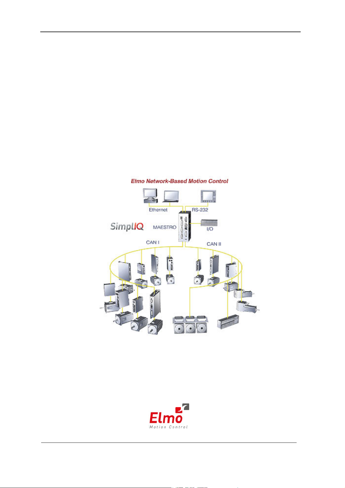
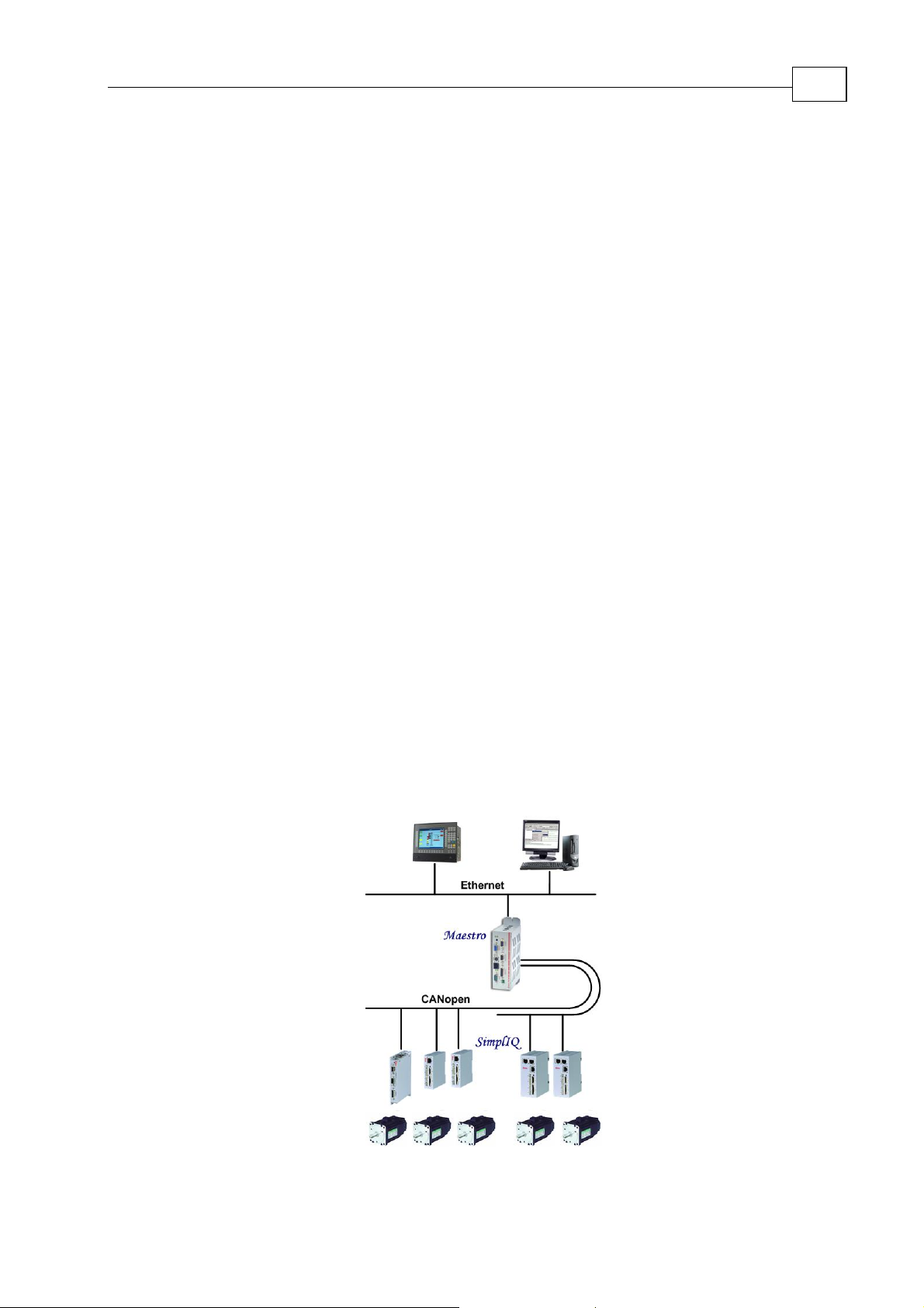
Elmo’s Maestro is a network-based multi-axis motion supervisor that operates in
conjunction with Elmo intelligent servo drives to provide a full multi-axis motion control
solution. The Maestro and the
workload in a distributed motion control architecture.
1.1 Maestro Highlights
The Maestro operates as a Multi-Axis Motion Supervisor to:
coordinate motion between various axes in synchronized interpolated mode
integrate event handling into motion control procedures
The Maestro operates as a CANopen Network Node Master for:
Network management (NMT)
Clock synchronization
Network Configuration
SimplIQ servo drives share the motion processing
1-1
The Maestro operates as an Ethernet - CAN gateway
The Maestro acts as a file archiver and distributor of:
Firmware – Maestro and intelligent drives
Multi-Axis User Applications – Maestro and intelligent drives
System Resources
The Maestro operates as a Multi-Axis Motion Analysis & Development tool:
Multi-Axis recording and analysis tools
Multi-Axis application development environment
The Maestro can be monitored through a web browser.
Machine
Programming
And Control
Multi-Axis
Motion Control
Single-Axis
Motion Control
Figure 1-1 Maestro Multi-Axis Supervisor Architecture
Page 13
Maestro Software Manual Introduction
MAN-MASSW (Ver. Q)
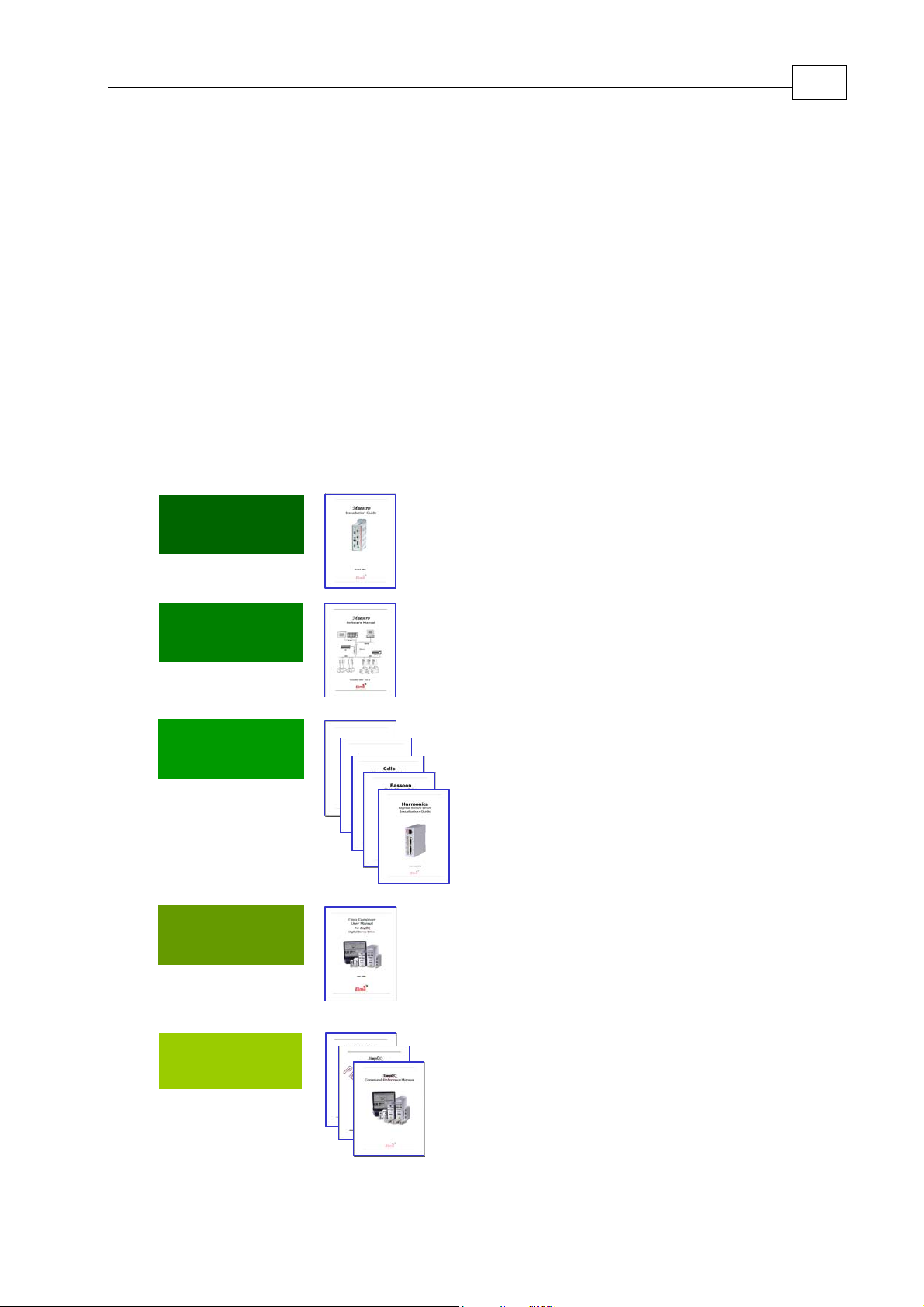
1.2 Supplementary Documents
This manual is part of a documentation set that, together, can be used to set up and
program the motion of any machine whose motors are controlled by Elmo
drives. Before you can use this manual you will need to carefully follow the instructions
in the Maestro Installation Guide to set up your Maestro.
The software described in this manual is provided on the CD that accompanies the
Maestro or as a download from Elmo's web site. In this manual it is assumed that you
have followed the software setup instructions in the Maestro Installation Guide and have
successfully installed the software.
At least one drive needs to be connected to the Maestro in order for it to function as a
motion controller. The
servo drives. Please read the Installation Guide that arrived with your servo drive before
setting it up. Servo drives are power devices so be careful.
SimplIQ manuals shown below explain how to set up and program
SimplIQ servo
1-2
Maestro
Setup
Maestro
Programming
Drive
Installation
Drive
Setup
Tuba
Cornet
Maes
tro
Maestro
Installation Guide
Maestro
Software Manual
SimplIQ
Digital Servo Drive
Installation Guide(s)
Composer User Manual
Drive / A x is
Programming
CANopen Implementation Guide
SimplIQ Software Manual
SimplIQ Command Reference Manual
Figure 1-2: Elmo Documentation Hierarchy
Page 14

Maestro Software Manual Introduction
MAN-MASSW (Ver. Q)
1.3 Command Specification
Commands for SimplIQ drives may be specified from the following sources:
User program A program loaded to the servo drive via one of the
communication options. After program execution begins, the
program is managed by the drive.
RS-232 Serial, point-to-point, short-range communication. Although this
method is rather slow, RS-232 is very easy to use and
requirements are minimal: a standard PC with serial port and
ASCII terminal software.
CANopen Serial, multi-drop, medium speed and medium-range
communication. This type of communication requires specialpurpose host hardware and software.
1-3
This manual describes the
Maestro commands that can be specified from each of these
sources. Most of the commands are equally available for all three sources. Certain
commands, however, are limited in scope according to type of program or
communication.
All the commands are available to CAN communication in text form through the OS
service, objects 0x1023 and 0x1024. In addition, the numerical set/get commands are
available to CAN users in short PDO form, called the “binary interpreter.” The binary
and the OS SCAN interpreters are described fully in the CAN manual.
CANopen may also be used to manipulate the drive using the object dictionary (OD)
method, which is the native CAN method. This manual does not cover OD manipulations
with CANopen; refer to the “Object Dictionary” section of the CANopen manual for full
explanations.
The
Maestro drive responds to many privileged commands — such as those used by the
Composer setup wizard — that are not documented in this manual.
1.4 Scope
This manual includes the complete list of commands used by the Maestro servo drives.
The commands are presented in two ways:
A task-related listing
Alphabetically
In the task-related reference, the commands are sorted into groups of related commands.
Each group is presented in a table listing the commands with basic descriptions. The
alphabetical command listing provides a detailed explanation of each command, with
examples and references to the
SimplIQ Software Manual when necessary.
Page 15
Maestro Software Manual
MAN-MASSW (Ver. Q)
Chapter 2: Functional Overview
This chapter takes a look at the organization of Maestro software.
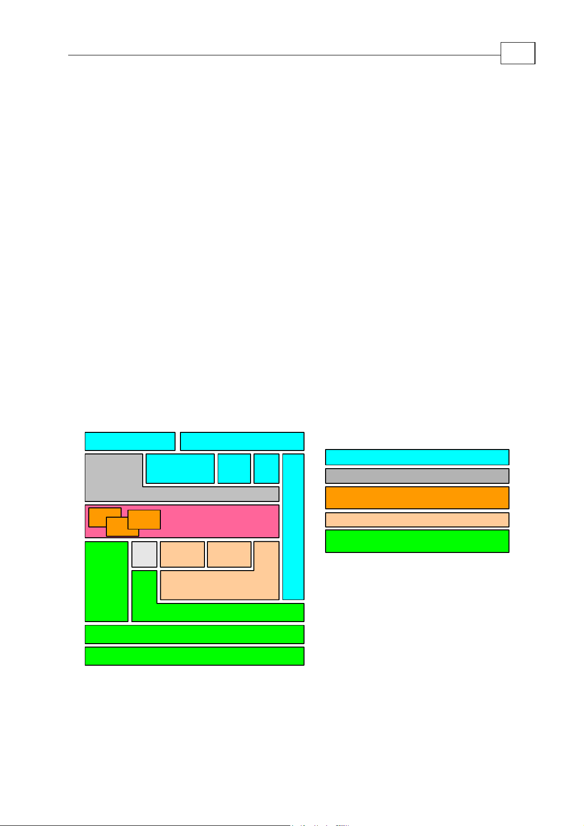
2.1 Functional Block Diagram
The Maestro’s functionality can be organized into the 5 groups shown below.
The first group (Host Communications Services) contains the standard interfaces and
protocols that enable the
The Command Line Interpreter is a utility that enables individual commands to be executed
immediately by either the
The Kernel is the part of the Maestro that executes user programs.
Maestro to communicates with the “outside world”.
Maestro or by a SimplIQ drive on a specified axis.
2-1
The Motion Manager sends commands and information to all axes and receives
information so that it can coordinate motion between all the axes.
The Maestro is designed to manage multiple axes on a CAN Open network. The CAN
Network Communication Server contains the CAN Open interfaces and protocols that
enable the
Maestro to do so.
Key:
Host Communication Services
Command Line Interpeter
Virtual Machines
(for executing User Programs)
Motion Manager
CAN Network
Communications Server
Virtual
Machine
Host
API
Command Line Interpeter
Virtual
Machine
Virtual
Machine
I/O
Kernel
Group
EthernetRS - 232
WEBTelNet
Gateway
Vector
CAN
Bus
Axis Manager
Services
CANopen (DS-301)
CANopen Master
CANopen API
Figure 2-1 The Maestro's Building Block
Page 16

Maestro Software Manual Functional Overview
MAN-MASSW (Ver. Q)
2.2 Host Communications Services
A host application can access the Maestro using either a TCP/IP or RS-232 services.
Processes carried out through host communication include:
Transfer of operating instructions (e.g. for running a program or killing it) to the
Maestro
Transfer operational data (such as the trajectory of the next motion)
Status requests
Debugging
Generation of a “transparent path” from a Composer program to any single end-unit
Host communication is used to execute different tasks, including:
Processing of interpreter commands
Maintenance and file download/upload
Processing of direct-axis interpreter commands
2-2
CANopen gateway
2.3 Command Line Interpreter
CLI commands that are sent to the Maestro are either executed by the Maestro itself or
are forwarded directly to the specified axis for immediate execution.
The CLI currently supports the following commands:
Initialization commands
Commands for collect information
Axis commands
Vector commands
Group command
2.4 The Kernel
One of the main Kernel functions is running Maestro User Programs. The part of the
Kernel which executes the User Programs is the Virtual Machine which enables multiaxis programming. Each task (program) can work independently of the other tasks by
running a separate virtual machine. Communication and synchronization between tasks
can be performed by using global variables. Multiple tasks can be used to run different
machine functions in parallel.
Page 17

Maestro Software Manual Functional Overview
MAN-MASSW (Ver. Q)
2.5 Motion Manager
The Motion Manager is the portion of the Kernel which provides services for the I/O and
the following motion objects:
Axis
Group
Vector
2.6 CANopen Network Communications Services
The CANopen Network Communication is the portion of the Kernel which provides the
following functionality:
CANopen Bus services
CANopen DS 301 Protocol
2-3
CANopen Master
CANopen API
Page 18

Maestro Software Manual
MAN-MASSW (Ver. Q)
Chapter 3: Host Communications
This chapter explains how to set up the Workspace to work with a specific Maestro as a
host.
3.1 Setting Up the Host through Elmo's Studio
A Select Maestro pick list pops up when starting a new worksheet for the first time. The
window contains a list of Maestros currently attached to the network. The IP Address of the
Maestro and its name are listed. Select the Maestro you plan to work with and click OK.
3-1
Figure 3-1 The Maestro Selection Window
3.2 Verifying or Changing the Host
To verify that you have set up the correct Maestro as the host, or to change to another
Maestro, move the cursor into the File Viewer and click on the right mouse button. When
the menu pops up select Workspace Settings. This will cause the Workspace Settings
window to open. If the IP Address is wrong, click the Find button to open the Select
Maestro window.
Figure
3-2 Right Mouse Button
Selection Options
Figure 3-3 The Workspace Settings Window
Page 19
Maestro Software Manual Host Communications
MAN-MASSW (Ver. Q)
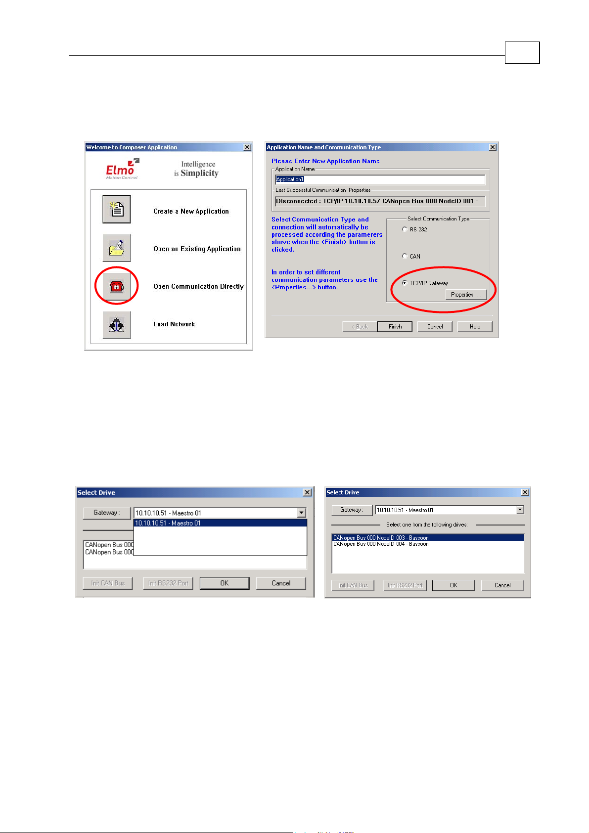
3.3 Choosing the Host through the Composer
Select Start/Programs/Elmo/Composer to start Elmo's Composer and check the setup.
3-2
1. In the Welcome menu select the Open Communication Directly option.
2. In the Application Name and Communication Type dialog box check the TCP/IP
Gateway option and click the Properties button.
3. In the Select Drive dialog you should see at least one Maestro in the Gateway list.
Select it.
4. Go to the drive window, select one of the drives and click OK to open
communications with the selected drive.
5. If the Composer has no information about the device that was selected, it will
upload the device info. That could take a minute or two.
6. If all is connected properly, the Smart Terminal window in the Composer will
open.
Page 20

Maestro Software Manual
MAN-MASSW (Ver. Q)
Chapter 4: General and Motion Instructions; Configuration Tools
This chapter describes the Maestro input/output and motion objects, instructions and CAN
configuration tools.
The Maestro Multi-Axis Controller supports the following set of Input/Output Objects:
4-1
• Internal Maestro I/O Objects: the
eight Digital Outputs and four Analog Inputs.
• External CAN I/O: the
to the CANopen DS 401 protocol and use the I/Os on Elmo SimplIQ
devices.
The Maestro Multi-Axis Controller supports the following set of Motion Objects:
• Axis is the most basic
the motion of a single motor/axis.
• Vector2D: This object is comprised of two axes of the same type and it
is used to define two dimensional trajectories.
• Vector3D: This object is comprised of three axes of the same type and it
is used to define two dimensional trajectories.
• Group is a composite
Maestro axes of the same type. This object can be used to
more
synchronize the operation of all the axes in the group.
All motion objects use the same set of Motion Instructions, which include:
Maestro can control external I/Os that conform
Maestro motion object and it is used to control
Maestro motion object that is comprised of two or
Maestro has eight Digital Inputs,
• Commands – instructions sent to an axis (these are similar to the commands
used by SimplIQ drives and are described in the SimplIQ Command Reference).
• Properties – system parameters used to set the behavior of the Maestro.
• Functions – a pre-defined set of motion functions.
There is also a unique set of functions called CAN Bus Configuration Tools that are used to
set up an LSS slave.
Motion instructions can be sent from a terminal or from a
Maestro user program.
Page 21

Maestro Software Manual General and Motion Instructions
MAN-MASSW (Ver. Q)
Table 4-1 Motion Properties and Functions
Axis
Properties
Vector
Properties
Group
Properties
CAN Input
Properties
VAC flr backup
VAE irq
VBT GBT mhl
VCR mlh
VDC msk
ADI plr
ADT VDT
AEL GEL
AEH GEH
AEM GEM
AFP VFP
AID VID GID
ALN VLN
CAN Output
Properties
AMC VMC GMC erm
VNT erv
APE flr
VPE plr
APP VPP
VSC message
VSD
VSE
VSM GSM
VSP
VSR
ATM VTM GTM
ATP
VTT
VUM
VVE
VXT
General
Functions
businfo
bye, quit, or exit
command
date
dynamicip
errlevel
error
find
format
halt
hbperiod
hbrem
ipconfig
isok
kill
list
load
messageex
name
nodeguard
nodeinfo
property
restart
restarta
restartd
restarte
resauto
save
staticip
sync
systime
systimex
time
tstamp
tstampver
umauto
umstart
umstatus
umstop
ver
4-2
Page 22

Maestro Software Manual General and Motion Instructions
MAN-MASSW (Ver. Q)
2D, 3D &
Axis
Functions
Group
Vector
Group
Functions
CAN Configuration
Tools (Functions)
Functions
addcircle plss_activate_bt m_din
adddwell plss_config_bt
addline
addpoint addpoint
plss_config_nid
plss_inq_addr
addsplinep plss_inq_nid
attach attach
circle
clears
detach detach
dotrj dotrj
ends ends
plss_inq_product
plss_inq_rev_num
plss_inq_ser_num
plss_inq_vendor
plss_master_bt
plss_start
error error error plss_store_config
isok isok isok plss_stop
line plss_sw_glb
startstp splinee
plss_sw_sel
splinep
trj splines
startp
starts
trj
m_dout.plr
Maestro I/O
Functions
m_din[]
m_dout
m_dout[]
m_ain[]
m_ain[].offset
m_din.polarity,
m_din.plr
m_dout.polarity,
4-3
Page 23

Maestro Software Manual
MAN-MASSW (Ver. Q)
4.1 General Functions
Note: Entering a question mark from the terminal before any function name opens the
help text for the function. (Terminal only)
Function
backup
- restart the Maestro with the previous configuration
4-4
Call Format
Limitations
Function
Call Format
Parameters
Limitations
Example
Function
Call Format
Limitations
Example
Function
Call Format
backup
Terminal only
baudrate
- get the CAN bus baud rate
baudrate(BusID)
BusId - CAN bus ID number
Terminal only
baudrate(0)
businfo
- get CAN Bus information
businfo <bus_number> - CAN bus number (default value = 0)
Terminal only
businfo 1
bye, quit or exit
- close the current session
bye
Limitations
Function
Call Format
Limitations
Function
Call Format
Limitations
Example
Terminal only
command
- gets help text with the general structure for the motion
object commands.
?command
Terminal only
date
- get (or set) the current date
date - To change the date, enter a date according to the format
DD.MM.YYYY.
Terminal only
date 16.11.2005.
Page 24

Maestro Software Manual General and Motion Instructions
MAN-MASSW (Ver. Q)
4-5
Function
Call Format
Return Value
Limitations
Example
Function
Call Format
Example
Function
Call Format
Limitations
dynamicip
– configures the Maestro Network Parameters to work with
a DHCP Server (dynamic IP addressing)
dynamicip
EnableDHCP: 1
Terminal only. Restart (power off/on) the Maestro controller to apply a
new dynamic IP address
dynamicip
EnableDHCP: 1
errlevel
- set the error stack level
errlevel( <level> )
<level> - preferred error level
errlevel(3)
error
– set error level 3
- get the error stack from the Maestro Multi-Axis Controller
error - get all errors with the current error level
error <level> - get all errors with the specified error level
Terminal only
Example
Function
Call Format
Limitations
Example
Function
Call Format
Limitations
Function
Call Format
Limitations
error 3
– get all errors with error level 3 only
find - Search for an object according to the object’s logical name. If the
object exists, the information is displayed as a “list”. If the object does
not exist, the Maestro returns “Object not found”.
find <object_name>
Terminal only
find axis_1
format – displays the help text that defines how to format a binary,
hexadecimal or floating-point number.
?format.
Terminal only
halt - halt the virtual machine
<name of virtual machine>.halt
Terminal only
Example
vm.halt
Page 25

Maestro Software Manual General and Motion Instructions
MAN-MASSW (Ver. Q)
4-6
Function
Call Format
Parameters
Return Value
Example
Function
Call Format
Parameters
Return Value
Example
hbperiod
- set heartbeat control period
hbperiod(int <bus_number>,int<period>)
<bus_number> - the CAN bus number to use to send heartbeat
messages
<period> - the interval between heartbeat messages in milliseconds (0–
for cancel).
OK or FAILED: Error message
hbperiod(0,1000) – the system uses bus number 0 to send a heartbeat
message every 1000 ms.
hbrem
- remove the node from heartbeat control
hbrem(int <bus_number>,int<node number>)
<bus_number> - CAN bus number
<node number> - the CAN node number of the node to remove from
heartbeat control
OK or FAILED: Error message
hbrem(0,1)
– on CAN bus 0, remove node 1 from heartbeat control
Function
Call Format
Return Value
Limitations
Example
Function
Call Format
Return Value
Limitations
Function
ipconfig
– display the current network configuration type, IP address
and subnet mask
ipconfig
Displays the network configuration type, IP address and subnet mask
Terminal only
ipconfig
EnableDHCP: 1
DhcpIPAddress: 10.10.20.57
DhcpSubnetMask: 255.255.255.0
isok
- verify the Maestro Multi-Axis Controller status
Isok
OK: Ok FAILED: Error message
Terminal only
kill - kill all programs
Call Format
Return Value
Limitations
Kill
OK: the number of killed programs, or FAILED: Error message
Terminal only
Page 26

Maestro Software Manual General and Motion Instructions
MAN-MASSW (Ver. Q)
Function
list - gets a list of all the Maestro objects. An object can be a motion
object (axis, vector, etc.) or a virtual machine.
4-7
Call Format
list [-key:
attribute] … [-key:attribute]
Parameters:
[-b:id] - get information for the specified CAN Bus
[-n] - get information about nodes DS301
[-i] - get information about IO DS401
[-a[:attribute]] - get information about axes. Attributes: target object type. Can be:
e[lmo] - Elmo motion drivers only
402 - DS402 profile motion drivers only
[-v[:attribute]] - get information about vectors. Attributes: target object type. Can be:
e[lmo] - vectors of Elmo motion drivers only
402 - vectors of DS402 profile motion drivers only
[-g[:attribute]] - get information about groups. Attributes: target object type. Can be:
e[lmo] - groups of Elmo motion drivers only
402 - groups of DS402 profile motion drivers only
[-t] - get information about trajectories
[-p[:attribute]] - get information about programs. Attributes: target object type. Can
be:
r[un] - running programs only
p[ause] - paused programs only
h[alt] - halted programs only
a[bort] - aborted programs only
f[ile] - all programs in the device file
Limitations
Example
Function
Call Format
Limitations
[-u] - get information about unrecognized objects
[-f] - get full information about current query
[-s] - get status of current motion object
Terminal only
list
list –b:0 -a
list -p:r
load
- loads the values of all global variables and arrays saved during
the previous save() function
load()
Program only
Page 27

Maestro Software Manual General and Motion Instructions
MAN-MASSW (Ver. Q)
4-8
Function
Call Format
Parameters
Example
Function
Call Format
Parameters
Example
Function
Call Format
Return Value
Limitations
message
- post a message to the host computer (no timestamp)
message(msgID, wParam, lParam) – posts a message without a
timestamp
msgID – user-defined message ID
wParam, lParam – user’s message data (Unsigned integer type)
message ( 0, a1.px, a2.px )
messageex - post a message to the host computer (with time stamp)
messageex(msgID, wParam, lParam) – posts a time-stamped message
msgID – user-defined message ID
wParam, lParam – user’s message data (Unsigned integer type)
messageex( 0, a1.px, a2.px )
name
- get (or set) the logical device name
name – gets the device name
name <device_name> - sets the device name
Device name
Terminal only
Function
Call Format
Example
Function
Call Format
Limitations
Example
Function
nodeguard
– set the nodeguard control period
nodeguard(int <bus_number>,int <node number>,int<period>)
bus_number - CAN bus ID
node number – CAN node ID
period - the interval between nodeguard messages in milliseconds (0–to
cancel).
nodeguard (0,1,500) – On CAN bus 0, sets the interval between
nodeguard messages arriving at CAN node 1 to 500 milliseconds.
nodeinfo
– gets the CAN node information
nodeinfo(int <bus_number>,int < node number >)
bus_number - CAN bus ID
node number – CAN node ID
Terminal only.
nodeinfo(0,1)
property
- gets the help text for the motion object property
Call Format
Limitations
? property
Terminal only
Page 28

Maestro Software Manual General and Motion Instructions
MAN-MASSW (Ver. Q)
4-9
Function
Call Format
Limitations
Function
Call Format
restart - Restarts the Maestro and:
• Closes all existing objects
• Kills all virtual machines
• Restarts the Maestro kernel
• Applies the sessions and objects according to the existing
configuration file.
restart
Terminal only
restarta - Restarts the Maestro and:
• Closes all existing objects
• Kills all virtual machines
• Restarts the Maestro kernel
• Applies the sessions and objects according to the existing
configuration file.
• Starts the AUTOEXEC program (if it exists).
restarta
Limitations
Function
Call Format
Limitations
Example
Function
Call Format
Limitations
Terminal only
restartd
configuration
- restarts the Maestro kernel with the default
and sets the baud rate for each CAN bus.
restartd() – for baud rate 500 (default setting)
restartd(baudrate1, baudrate2) –baud rate 0 is not used. If the default
baud rate is not selected, a separate baud rate for each CAN bus must
be specified. If a baud rate for one bus is omitted, an error message is
displayed.
Terminal only
restartd(1000, 1000)
restarte
.
bus
- restarts the Maestro kernel without running the CAN
restarte()
Terminal only
Page 29

Maestro Software Manual General and Motion Instructions
MAN-MASSW (Ver. Q)
4-10
Function
Call Format
Limitations
Example
Function
Call Format
Limitations
Function
Call Format
rsauto
- get (or set) the RS-232 autorun parameter
rsauto() – to get the current autorun parameter
rsauto(val) – to set the current autorun parameter
val can be 0 or1
Terminal only
rsauto(1) – allows the RS-232 bus to access the Command Interpreter
rsauto(0) – does not allow the RS-232 bus to access the Command
Interpreter
save
- to save the values of all the global variables and arrays
save()
Program only
staticip
– configures the Maestro Network parameters to work with
a static IP address
staticip(ip_address, subnet_mask)
ip_address - new IP Address of Maestro device
subnet_mask - new Subnet Mask of Maestro device
Return Value
Limitations
Example
Function
Call Format
Parameters
Return Value
Example
Function
IP Address and Subnet Mask, Network configuration type,
Terminal only. Restart (power off/on ) Maestro to apply Static IP
address.
staticip (10.10.20.57, 255.255.255.0)
IPAddress: 10.10.20.57
SubnetMask: 255.255.255.0
EnableDHCP: 0
sync
- begin sending SYNC messages to a CAN bus
sync (int <bus_number>,float<sync_period>)
<bus_number> - which CAN bus to send the SYNC messages to
<sync_period> - the value of the SYNC period, in milliseconds
OK or FAILED: Error message
sync(0,20) – for bus number 0 activate the send sync every 20
milliseconds.
systime
- returns the system-defined time in milliseconds
Call Format
Function
Call Format
systime()
systimex
systimex()
- returns the CAN bus time in microseconds
Page 30

Maestro Software Manual General and Motion Instructions
MAN-MASSW (Ver. Q)
Function
- get (or set) the current time
time
4-11
Call Format
Limitations
Function
Call Format
Parameters
Return Value
Example
Function
Call Format
Limitations
Time
Terminal only
tstamp
- set the timestamp period
tstamp(int <bus_number>,int<period>)
<bus_number> which CAN bus sends the timestamp
<period> - specifies how many sync periods must pass before the new
timestamp is set.
OK or FAILED: Error message
tstamp(0,5)
sync periods.
5
umauto
– for bus number 0, send a timestamp message after each
- get (or set) the user module autorun parameter
umauto() – to get the current autorun parameter
umauto(val) – to set the current autorun parameter
val can be 0 or 1
Terminal only
Function
Call Format
Limitations
Function
Call Format
Limitations
Function
Call Format
Limitations
Function
Call Format
Limitations
umstart
- run the user module
umstart()
Terminal only
umstatus
- get the user module status
umstatus()
Terminal only
umstop
- terminate the user module
umstop()
Terminal only
ver
- get current Maestro version
Ver
Terminal only
Page 31

Maestro Software Manual General and Motion Instructions
MAN-MASSW (Ver. Q)
4.2 Axis
4.2.1 Axis Motion Commands
SimplIQ commands can be sent to the drive through the Maestro terminal or from a Maestro
program.
Motion Commands are described in detail in the SimplIQ Command Reference Manual. When
a Motion Command is used to program the
• To send a command to set a parameter value:
<Axis name>.Command=<Value>
• To receive a parameter:
<Value>=<Axis name>.Command
For example:
A1.UM = 2
A1.MO = 1
A2.BG
A2.ST
Maestro, its syntax is as follows:
4-12
4.2.2 Axis Properties
Motion properties apply to Maestro programs only. Axis related properties are listed
below:
• To set a property value:
<Axis name>.Property=<Value>
Motion properties apply to
below:
• To set a property value:
<Axis name>.Property=<Value>
• To get a property value:
<Value>=<Axis name>. Property
Property ADI - Axis Drive Input event initialization
Explanation This property is used to control the message mechanism from the
Note 0 – event disabled, 1 – event enabled.
Maestro programs only. Axis related properties are listed
drive to the Maestro.
The message mechanism notifies the Maestro when a Digital Input
(DI) event has occurred.
When this property is enabled, the Maestro can react to DI events
with a callback function. (The user must define the callback
function in his program).
Default 0
Limitation 0-1
Example A1.ADI=1 (see Appendix B.4.5.2 InputOutputTest1)
Page 32

Maestro Software Manual General and Motion Instructions
MAN-MASSW (Ver. Q)
Property ADT - Axis Delay Time – delay the start of the "do trajectory" (dotrj)
command
Explanation The ADT property defines when to start the trajectory and must be
specified when dotrj commands are used. The default value is 20 ms.
Dimension Milliseconds
Default 20
Limitation 20-254
Type Unsigned integer
Property AEL - CAN Encoder Low Limit
Explanation AEL is needed when Axis works as a CAN Encoder slave. The
property provides Encoder limitations.
Limitation 0-0x4000
Type Integer
Property AEH - CAN Encoder High Limit
4-13
Explanation AEM is needed when Axis works as CAN Encoder slave. The property
provides Encoder limitations.
Limitation 0-0x4000
Type Integer
Property AEM - CAN Encoder interpolation time
Explanation AEM is needed when Axis works as CAN Encoder slave. The property
provides mode initialization and interpolation (Sync) time definition.
Dimension Milliseconds
Limitation 1-64
Type Unsigned integer
Property AFP – Axis First Point
Explanation Defines the number of lines of a PVT table that are sent to the drive at
the start. SimplIQ drives are capable of storing 64 lines. Less than 64
lines are required for starting an axis as otherwise the start of the
other axis would be delayed. This would reduce the efficiency of the
system.
Default 5
Limitation 3 – 10
Type Unsigned integer
Page 33

Maestro Software Manual General and Motion Instructions
MAN-MASSW (Ver. Q)
Property AID – get axis ID
Explanation Used to get the NodeID of an axis. For example, in a callback function
the NodeID can be compared with a specific motion object so that
something specific can be done in each case (event / NodeID).
Limitation Read only
Type Unsigned integer
Example Function @input (BusID, NodeID, data)
switch(NodeID)
case a1.aid
val=1
case a2.aid
val=3
end
end
(see Appendix B.4.5.2 InputOutputTest1)
Property ALN – number of trajectory cycles for an Axis
4-14
Explanation Repeats predefined PVT motion.
Note 0 - infinite
Default 1
Limitation 0, 1 … N
Type Unsigned integer
Property AMC – Axis Motion Completed event initialization
Explanation Initialize Motion Event notifies the system that axis motion is
complete and continues to notify until turned off. This is intended for
when one axis starts only after another axis motion has stopped.
Note 0 – event disabled, 1 – event enabled.
Default 0
Limitation 0 – 1
Example (see Appendix B.4.6 Motion Completed Callback Samples)
Property APE – Axis Program Emit event initialization
Explanation To initialize a reaction (maestro callback function) upon calling the
emit(i) function in a SimplIQ program.
Note Bit field:
bit 0 – PDO1 (emit(1)), bit 2 – PDO3 (emit(3)), bit 3 – PDO4 (emit(4))
bit value 0 – event disabled,
bit value 1 – event enabled.
Default 0
Limitation 0 – 15 (see Appendix B.4.4.2 EmitCallback)
Page 34

Maestro Software Manual General and Motion Instructions
MAN-MASSW (Ver. Q)
Property APP – Axis Points in Portion - number of PVT points in portion of
PVT trajectory
Explanation Limits the number of PVT lines sent to a drive. The Maestro
communicates with the drive first to see if space is available.
Default 5
Limitation 3 – 10
Type Unsigned integer
Property ATM – Axis Tabulated Motion– used to prepare the axis for PVT motion
Explanation Prepares axis for PVT motion.
Default 0
Limitation 0 – disable, 1 - enable
Type Unsigned integer
Example A1.atm=1
Property ATP – Last motion complete position
4-15
Explanation Axis position is sent with event notifications automatically with the
Maestro (for example: "last position 1001"). The information can be
retrieved with an x=a.atp command. In other words, this property
contains the current position and is readable.
Default 0
Limitation read only
Type integer
Page 35

Maestro Software Manual General and Motion Instructions
MAN-MASSW (Ver. Q)
4.2.3 Axis Functions
Motion functions apply to Maestro programs only. Axis related functions are listed below:
• To call a function:
<Return Value>=<Axis name>.Function[([Parameters])]
Function addpoint - add PVT point to user's trajectory sequence
Call Format < Axis_name>.addpoint(<Pos >,<Vel >, <T>)
Parameters <Pos > - position for PVT point (counts),
<Vel > - velocity for PVT point (counts per second),
<T> - interpolation period for PVT point (milliseconds)
Return Value OK or FAILED: Error message
Example
Function dotrj – Do Trajectory
a1.addpoint(1000, 30000, 10)
For more information see the starts and ends function
(see Appendix B.1.2.2 Add Point Sample)
4-16
Explanation Used to initialize the PVT mechanism and load the initial portion of the
PVT trajectory table to an axis and start motion.
Start motion is delayed. The delay specified by the ADT command.
The default delay value is 20 ms.
By comparison the trj command requires a bg command to start motion.
Call Format <Axis name>.dotrj(<Trajectory name>)
Parameters <Trajectory name> - name of PVT table (trajectory)
Return Value OK: Trajectory name
FAILED: Error message
Example A1.dotrj(table)
for axis name A1 run trajectory name “table”
(see Appendix B.1.2.2 Add Point Sample)
Function
ends - user's trajectory sequence for Axis motion object
(latest operator in startp(starts) – ends sequence)
Call Format < Axis_name>.ends()
Return Value OK: Ok
FAILED: Error message
Example a1.startp(mytable) the trajectory name mytable
a1.addpoint(10, 1000, 10)
a1.addpoint(1000, 30000, 10)
………….
a1.addpoint(5000, 1000, 10)
a1.ends() after this the trajectory named “mytable” will contain the user’s PVT
table
(see Appendix B.1.2.1 Circle Sample)
Page 36

Maestro Software Manual General and Motion Instructions
MAN-MASSW (Ver. Q)
4-17
Function
error – to get motion object last error
Call Format <Axis name>.isok
Return Value
OK: Ok ()
FAILED: Error message
Example A2.error
Function isok – used to verify motion object status
Call Format <Axis name>.isok
Return Value OK: Ok
FAILED: Error status
Example A2.isok
Function startp - begin user’s PVT trajectory sequence for an Axis
first operator in startp(starts)–ends sequence
Call Format < Axis name>.startp()
< Axis name>.startp(<Trajectory name >)
Parameters <Trajectory name> - name of Axis PVT table (trajectory) to save
Example a1.startp(mytable) – begin user’s PVT trajectory named “mytable”
For more information see the ends function example.
(see Appendix B.1.2.2 Add Point Sample)
Function trj – used to initialize the PVT mechanism and load a PVT trajectory table
to an axis
Call Format <Axis name>.trj(<Trajectory name>)
Parameters <Trajectory name> - name of PVT table (trajectory)
Return Value OK: Trajectory name
FAILED: Error message
Example A1.trj(table); A1.bg
for axis name A1, run trajectory name “table ”
Page 37

Maestro Software Manual General and Motion Instructions
MAN-MASSW (Ver. Q)
4.3 Vector
4.3.1 Vector Motion Commands
Vector commands can be sent simultaneously or serially according to VSM value simultaneously to a Vector or serially to individual axes (components of a vector). However,
only the parcel sent serially to the axes provides a reliable check of operating performance
results. When commands are sent individually, in a serial manner, the results of each
motion can be checked. If a vector is sent as a group (simultaneously), the results cannot be
checked.
A vector is a set of axes that provide two or three dimensional interpolated motion.
When a vector is active, the member axes can receive commands not only from it, but also
from the axes' objects.
A Vector cannot be activated if one of its member Axes is a member of another active
Vector. Access condition is set by attach/detach operator
• To send a set parameter value:
< Vector name>.Command [=<Value>]
For example:
V1.AC = V1.DC=1000000;
V1.MO = 0;
V2.BG;
V2.ST.
4-18
4.3.2 Vector Properties
• To set a property value:
< Vector name>.Property=<Value>
• To get a property value:
<Value>=< Vector name>. Property
All properties are valid for Vector2D and Vector3D
Property
Dimension
Default
Limitation
Type
Example
Property
Explanation
Default
VAC - vector acceleration
Counts per second
28000000
squared
Unsigned integer
(see Appendix B.1.2.1 Circle Sample)
VAE - calculated acceleration margin
Prevents the Maestro's calculated trajectory from exceeding the
maximum Axis acceleration.
0.9
Limitation
Example
Property
0-1
Type
VBT - synchronized start command delay
Float
Page 38

Maestro Software Manual General and Motion Instructions
MAN-MASSW (Ver. Q)
4-19
Explanation
Dimension
Default
Limitation
Type
Property
Note
Default
Limitation
Type
Property
Dimension
Once the begin command is sent, the Vector motion begins after the
delay specified by the VBT value. This command property is only
valid when the sync command is used.
Milliseconds
20
2-254
Unsigned integer
VCR - constant PVT table resolution flag
1 - constant PVT resolution (each time interval is the same)
0 – various PVT resolution (the time intervals vary to fine tune the
motion and make it more accurate)
0
0, 1
Unsigned integer
VDC - vector deceleration
counts per second squared
Default
Type
Example
Property
Explanation
Dimension
Default
Limitation
Type
Example
28000000
Unsigned integer
(see Appendix B.1.2.1 Circle Sample)
VDT – defines delay for dotrj command
VDT is needed when the DOTRJ command is used. It defines when
to start the trajectory. The default delay is 40ms.
Milliseconds
40
20-254
Unsigned integer
(see Appendix B.1.2.2 Add Point Sample)
Page 39

Maestro Software Manual General and Motion Instructions
MAN-MASSW (Ver. Q)
Property
VFP –number of lines downloaded in the first portion of a PVT
trajectory
4-20
Explanation
Default
Limitation
See also
Example
Property
Limitation
Type
Example
Property
SimplIQ drives work according to information that is in their PVT
table. If the table is empty they do not drive the motor. SimplIQ
PVT tables have 64 lines. If the Maestro were to fill each drive
serially, then motion could not start until after the last drive was
loaded. If, on the other hand, only a few lines of each PVT table
were filled, than motion could start relatively quickly. While the
motors are moving, more lines for each PVT table can be loaded.
There is a fine balance between loading the minimum number of
PVT lines and "starving" the drive. Each application is different.
The VFP command is used to find and then set the initial number
of PVT lines sent to a drive.
5
3 – 10
Type
Unsigned integer
VPP – single points portion size for PVT trajectory
(see Appendix B.1.6 Polygon Sample)
VID – get the group ID of the vector
Read only.
Unsigned integer
(see Appendix B.4.6.1 MCompleteCallback)
VLN – number of trajectory cycles for a vector; used to repeat
predefined PVT motion.
Note
Default
Limitation
Type
Property
Explanation This notifies the system that vector motion is complete and
0 - infinite
1
0, 1 … N
Unsigned integer
VMC – vector motion completed event initialization
continues to notify it until turned off. For example, the X-Y table
on a drilling machine needs to come to a stop before the Z-axis
Note
Default
Limitation
Example
drill head starts moving.
0 – event disabled, 1 – event enabled.
0
0 – 1
(see Appendix B.4.6.1 MCompleteCallback)
Page 40

Maestro Software Manual General and Motion Instructions
MAN-MASSW (Ver. Q)
4-21
Property
Explanation
Dimension
Default
Limitation
Type
See also
Example
Property
Explanation
Dimension
Default
Type
See also
Property
VNT – low limit of calculated PVT
trajectory step time
Set/get PVT trajectory min step time
Milliseconds
2
1–255
Unsigned integer
VXT (max step time)
(see Appendix B.1.6 Polygon Sample)
VPE – calculated position error for PVT trajectory
Difference between the theoretical trajectory and calculated
trajectory.
counts
100
Float
VVE - calculated velocity error for PVT trajectory
VPP – single point size portion for PVT trajectory
Explanation
Default
Limitation
Type
See also
Property
Explanation
Note
See also
Default
Limitation
The number of PVT lines sent to a drive at a time. This helps to
"distribute" the information evenly across a multi-axis system so
that no axis is "starved" of information.
5
3 – 10
Unsigned integer
VFP –number of lines downloaded in the 1
st
portion of a PVT trajectory
VSC – PVT trajectory smoothing curve mode
Used with addcircle and addline to smooth the operation of the
motor at corners or joints.
Available:
0-non smoothed
1-smoothed with max velocity (use the VSE command)
2-smoothed with fixed radius (use the VSR command)
3-smoothed with fixed dist from the corner (use VSD)
VSD, VSE, VSP, VSR
0
1 - 254
Type
Unsigned integer
Example
Appendix B.1.2.1 Circle Sample)
(see
Page 41

Maestro Software Manual General and Motion Instructions
MAN-MASSW (Ver. Q)
4-22
Property
Explanation
Dimension
Default
Example
Property
Dimension
Default
Example
Property
Note
Default
Limitation
Property
VSD – PVT trajectory smooth distance from the corner point
When using VSC smoothing mode 3, VSD defines the distance
from the "corner" (point of change of trajectory)
Counts
0
Type
(see Appendix B.1.3.1 )
Unsigned integer
d
d
VSE – velocity at the end of a segment in a PVT trajectory
Counts per second
0
Type
Float
(see Appendix B.1.3.1)
VSM – send vector command mode simultaneously or one after the
other (serially)
0 – simultaneous mode, use Group ID of Vector
1 – serial mode, use Node ID of members
0
0,1
Type
Unsigned integer
VSP – PVT trajectory fixed (profile) velocity
Explanation
When the trajectory is set for maximum velocity, fixed time or fixed
velocity, the VSP command sets the velocity.
Dimension
Default
Dependencies
Counts per second
0
In max velocity mode (vum = 1) vsp=the limit of max vel. value
In fixed time mode (vum = 2) vsp=the limit of max velocity value
In fixed velocity mode (vum = 3) vsp=fixed velocity value
Type
See also
Property
Explanation
Float
VUM (see Appendix B.1.1 Line Sample)
VSR– PVT trajectory smooth radius (curve mode VSC=2)
When using VSC smoothing mode 2, VSR defines the radius of the
curve at the "corner" (trajectory point of change)
Dimension
Default
Type
Counts
0
Unsigned integer
r
Page 42

Maestro Software Manual General and Motion Instructions
MAN-MASSW (Ver. Q)
4-23
Property
Explanation
VTM – PVT motion initialization
Used to prepare the vector for PVT motion when the trajectory is set
for maximum velocity, fixed time or fixed velocity.
VTM is used to initialize "ready-made" PVT tables as well as
trajectories created with the Motion Library.
Default
Limitation
Type
Example
Property
Explanation
0
0 – disable, 1 - enable
Unsigned integer
(see Appendix B.1.5.1 Circle-to-Line Sample)
VTT – defines PVT trajectory fixed time when VUM=2
VTT sets the time to perform the motion when using addline or
addcircle.
Dimension
Default
Milliseconds
0
See also VUM
Type
Property
Unsigned integer
VUM – PVT trajectory build mode (for the Maestro's
Mathematical Library)
Note
1 – max velocity mode
2 - fixed time mode
3 - fixed velocity mode
Default
Limitation
Type
3
0-254
Unsigned integer
See also VTT
Example
Property
Explanation
(see Appendix B.1.5.1 Circle-to-Line Sample)
VVE - calculated velocity error for PVT trajectory
Limit range of error in terms of velocity – PVT tables can be
calculated accurately for two of the three constraints – VVE tells the
Maestro to "loosen" the constraints on the velocity.
Dimension
Default
Limitation
Type
%
0.005
0-1
Float
Page 43

Maestro Software Manual General and Motion Instructions
MAN-MASSW (Ver. Q)
4-24
Property
Explanation
Dimension
Default
Limitation
Type
See also
Example
VXT – high limit of the calculated PVT trajectory step time
PVT trajectory maximum step time
Milliseconds
10
1–255
Unsigned integer
VNT (min step time)
(see Appendix B.1.6 Polygon Sample)
4.3.3 Vector 2D Functions
• To call a function:
<Return Value>=<Vector name>.Function [([Parameters])]
Function
Call Format
Parameters
Return Value
Example
Function
Call Format
Parameters
Example
Function
Call Format
Parameters
Return Value
Example
addcircle - add circle segment to trajectory sequence for a vector
motion object
<Vector name>.addcircle(int <Radius>,float <Start Angle>,float
<Sweep Angle>)
int <Radius> - radius of circle segment (counts)
float <Start Angle> - start angle of circle segment (degrees)
float <Sweep Angle> - sweep angle of circle segment (degrees)
OK or FAILED : Error message
Vec1.addcircle(rad, alpha, delta)
For more information see the vector ends function example.
(see Appendix B.1.5.1 Circle-to-Line Sample)
Polyline trajectory program examples can be found in
Samples Tutorial – Motion Library Tutorial Examples – Vector 2D
adddwell - add delay to a PVT trajectory at the end of a segment
adddwell(int delay)
int delay - delay value in millisecond
together with addline, addcircle ... (Appendix B.8.1)
addline - add linear segment to the polyline trajectory sequence for a Vector
motion object
<Vector name>.addline(int <Pos X>,int <Pos Y>)
int <Pos X>,<Pos Y> - destination position of linear segment (counts),
beginning of segment – current position
OK or FAILED : Error message
Vec1.addline(1000, 2000)
For more information see the vector ends function example.
(see Appendix B.1.5.1 Circle-to-Line Sample)
Polyline trajectory program examples can be found in
Samples Tutorial – Motion Library Tutorial Examples – Vector 2D
Page 44

Maestro Software Manual General and Motion Instructions
MAN-MASSW (Ver. Q)
4-25
Function
Call Format
Parameters
Return Value
Example
Function
Call Format
Parameters
Return Value
Example
Function
Explanation
Call Format
Return Value
Example
Function
Call Format
Parameters
Return Value
Example
addpoint - add PVT point to user's trajectory sequence to a Vector
<Vector name>.addpoint(int <Pos X>,int <Vel X>,int <Pos Y>, int<Vel Y>,
int <T>)
int <Pos X>,<Pos Y> - position for PVT point (counts),
int <Vel X>,<Vel Y> - velocity for PVT point (counts per second),
int <T> - interpolation period for PVT point (milliseconds) 0 - 255
OK or FAILED : Error message
Vec1.addpoint(1000, 30000, 2000, 40000, 10)
For more information see the vector ends function example.
(see Appendix B.1.2.2 Add Point Sample)
addsplinep - add two-dimensional point to the spline segment of the
polyline trajectory sequence
<Vector name>.addsplinep(int <Pos X>,int <Pos Y>)
The last point of the previous polyline segment or the first point of the
trajectory is automatically added to the spline segment. It means that the
minimal number of the addsplinep() operators that define the same spline
segment inside the polyline must be greater than or equal to 2.
This requirement is valid for every spline segment inside the polyline – not
only for the first one.
int <Pos X>,<Pos Y> - position of the point (counts)
OK or FAILED : Error message
Vec1. addsplinep (1000, 2000)
Polyline trajectory program examples can be found in
Samples Tutorial – Motion Library Tutorial Examples – Vector 2D
attach – used to synchronize all members of the Vector according to the
resource file. The attach function must be called before the first vector
operation.
Sometimes two vectors "share" an axis. If the axis was used simultaneously
by both vectors, then errors will occur. Attach is used to tell the axis with
which vector to work.
< Vector name>.attach()
OK or FAILED : Error message
G1.attach() (see Appendix B.4.6.1 MCompleteCallback)
circle - make circle trajectory for vector motion object
<Vector name>.circle(int <Radius>,float<Start Angle>,float<Sweep Angle>)
int <Radius> - radius of circle trajectory (counts)
float<Start Angle> - start angle of circle trajectory (degrees)
float<Sweep Angle> - sweep angle of circle trajectory (degrees)
OK or FAILED : Error message
Vec1.circle(rad, alpha, delta);Vec1.bg
(see Appendix B.1.2.1 Circle Sample)
Page 45

Maestro Software Manual General and Motion Instructions
MAN-MASSW (Ver. Q)
4-26
Function
Call Format
Return Value
Example
Function
Explanation
Call Format
Return Value
Example
Function
Explanation
Call Format
Parameters
Return Value
Example
clears - remove user's or polyline trajectory sequence in a vector motion
object – erases previously sent commands before they are executed
<Vector name>.clears()
OK or FAILED : Error message
Vec1.clears()
Circle trajectory program examples can be found in Samples Tutorial –
Motion Library Tutorial Examples – Vector 2D
detach – cancel vector synchronization
Sometimes two vectors "share" an axis. If the axis was used simultaneously
by both vectors, then errors will occur. Detach is used to free the axis from
the vector with which it is working.
< Vector name>.detach()
OK or FAILED : Error message
V1.detach() (see Appendix B.4.6.1 MCompleteCallback)
dotrj – do trajectory
Used to initialize the PVT mechanism on each of the vector's axes, load the
initial portion of the PVT trajectory table to each axes and start motion. Start
motion is delayed by 20 ms unless otherwise specified by the VDT
command.
The trj command requires a BG command to start motion.
<Vector name>.dotrj(<Trajectory name>)
<Trajectory name> - name of Vector PVT table (trajectory)
OK : Trajectory name
FAILED : Error message
V1.dotrj(table)
for vector name v1 run trajectory name “table ”
(see Appendix B.1.2.2 Add Point Sample)
Page 46

Maestro Software Manual General and Motion Instructions
MAN-MASSW (Ver. Q)
4-27
Function
Call Format
Return Value
Example
Function
Call Format
Return Value
Limitation
Example
Function
Call Format
Return Value
Limitation
ends - closes a polyline trajectory sequence and a sequence of user defined
PVT points
<Vector name>.ends()
OK or FAILED : Error message
v1.startp(mytable) - begin the trajectory name mytable
v1.addpoint(10, 1000, 20, 2000, 10)
v1.addpoint(1000, 30000, 4000, 50000, 10)
………….
v1.addpoint(5000, 1000, 4000, 2000, 10)
v1.ends() - after this, the trajectory name “mytable” contains the user’s PVT
table
* * *
v1.start(mytable) - begin the polyline trajectory "mytable"
v1.addline(1000,2000)
v1.addcircle(1000, 180, -180)
………….
v1.addline(5000, 1000)
v1.ends() - after this the trajectory file “mytable” contains an updated PVT
table
(see Appendix B.1.3.1 Line-to-Line Sample)
Polyline trajectory program examples can be found in
Samples Tutorial – Motion Library Tutorial Examples – Vector 2D
error – request info about the last error
<Vector name>.isok
OK or FAILED : Error message
Terminal only
V.error
isok – used to verify if all OK
<Vector name>.isok
OK or FAILED : Error message
Terminal only
Example
Function
Call Format
Parameters
Return Value
Example
V.isok
line - builds a linear trajectory from point to point
<Vector name>.line(int <Pos X>, int <Pos Y>)
int <Pos X>,<Pos Y> - destination position of linear trajectory (counts),
beginning of trajectory – current position
OK or FAILED : Error message
Vec1.line(1000, 2000); Vec1.bg (see Appendix B.1.1 Line Sample)
Line trajectory program examples can be found in
Samples Tutorial – Motion Library Tutorial Examples – Vector 2D
Page 47

Maestro Software Manual General and Motion Instructions
MAN-MASSW (Ver. Q)
4-28
Function
Call Format
Return Value
Example
Function
Call Format
Parameters
Return Value
Example
Function
Call Format
Parameters
Return Value
Example
splinee - closes a spline trajectory sequence for Vector2D and Vector3D
objects
<Vector name>.splinee()
<Vector name>.splinee(int parameter)
If parameter≠0 three PVT tables for axes X,Y and gear are built
OK or FAILED : Error message
v1.splines(mytable) - begin the trajectory with file name mytable
v1.splinep(10, 1000)
v1.splinep(1000, 30000)
………….
v1.splinep(5000, 1000)
v1.splinee() - after this, the trajectory file named “mytable” will contain PVT
table for the spline trajectory
Program examples can be found in
Samples Tutorial – Motion Library Tutorial Examples – Vector 2D
splines - begin spline trajectory sequence for Vector2D and Vector3D objects
<Vector name>.splines()
<Vector name>.splines(<Trajectory name >)
<Trajectory name> - name of Vector PVT table (trajectory) to be saved
OK or FAILED : Error message
V1.splines() - begin spline trajectory calculation with saving the results in a
file with a standard name v1.trj
Program examples can be found in Samples Tutorial – Motion Library
Tutorial Examples – Vector 2D
splinep - add a point to the sequence of points that define the spline
trajectory
<Vector name>.splinep(int <Pos X>,int <Pos Y>)
The first point of the sequence must define the current position after homing.
This behavior differs from the spline segment inside a polyline where start
point is added automatically.
int <Pos X>, int Y> - spline point position (counts)
OK or FAILED : Error message
Vec1.splinep(1000, 30000)
Program examples can be found in
Samples Tutorial – Motion Library Tutorial Examples – Vector 2D
Page 48

Maestro Software Manual General and Motion Instructions
MAN-MASSW (Ver. Q)
4-29
Function
Call Format
Parameters
Return Value
Example
Function
Call Format
Parameters
Return Value
Example
Function
Call Format
Parameters
startp - begin user’s PVT vector trajectory sequence
<Vector name>.startp()
<Vector name>.startp(<Trajectory name >)
<Trajectory name> - name of Vector PVT table (trajectory) to be saved
OK or FAILED : Error message
V1.startp() - begin user’s PVT trajectory by saving the results in a file.
V1.startp(traj_name) - begin user’s PVT trajectory and save result in a file
with the name “traj_name”
For more information see the vector ends function example.
(see Appendix B.1.2.2 Add Point Sample)
starts - begin polyline trajectory sequence for a vector object
<Vector name>.starts()
<Vector name>.starts(<Trajectory name >)
<Trajectory name> - name of the Vector PVT table (trajectory) to be saved
OK or FAILED : Error message
V1.starts() - begin polyline trajectory calculation
For more information see the vector ends function example.
(see Appendix B.1.3.1 Line-to-Line Sample)
Polyline trajectory program examples can be found in
Samples Tutorial – Motion Library Tutorial Examples – Vector 2D
trj – used to initialize PVT mechanism and load the Vector PVT trajectory
table in each axis of the vector
<Vector name>.trj(<Trajectory name>)
<Trajectory name> - name of the Vector PVT table (trajectory)
Return Value
Example
OK or FAILED : Error message
v1.trj(table); v1.bg
for the vector v1 run trajectory “table ”
4.3.4 Vector 3D Functions
• To call a function:
<Return Value>=<Vector name>.Function [([Parameters])]
Function
Call Format
Parameters
Example
Function
Call Format
Parameters
adddwell - add delay to a PVT trajectory at the end of a segment
adddwell(int delay)
int delay - delay value in milliseconds
together with addline,
addline - add linear segment to the polyline trajectory sequence for the
vector motion object
<Vector name>.addline(int <Pos X>,int <Pos Y>, int <pos Z >)
int <Pos X>, int <Pos Y>, int <Pos Z> - destination position of linear segment
Page 49

Maestro Software Manual General and Motion Instructions
MAN-MASSW (Ver. Q)
(counts), beginning of segment – current position
Return Value
Example
OK or FAILED : Error message
Vec1.addline(1000, 2000,400)
Program examples can be found in Samples Tutorial – Motion Library
Tutorial Examples – Vector 3D
4-30
Function
Call Format
Parameters
Return Value
Example
Function
Call Format
Parameters
Return Value
Example
Function
Explanation
Call Format
Return Value
Example
Function
Call Format
addpoint - add PVT point to user's trajectory sequence to a vector
<Vector name>.addpoint(int <Pos X>,int <Vel X>,int <Pos Y>,<Vel Y>, int
<Pos X>, int <Vel Z> int <T>)
int <Pos X>,<Pos Y>, <Pos Z> - position for PVT point (counts),
int <Vel X>,<Vel Y>, <Vel Z> - velocity for PVT point (counts per second),
int <T> - interpolation period for PVT point (milliseconds) 0 - 255
OK or FAILED : Error message
Vec1.addpoint(1000, 30000, 2000, 40000, 3000, 5000, 10)
For more information see the vector ends function example
addsplinep - add three-dimensional point to the spline segment of the
polyline trajectory sequence
<Vector name>.addsplinep(int <Pos X>,int <Pos Y>, int <Pos Z>)
The last point of the previous polyline segment or the first point of the
trajectory is automatically added to the spline segment. This means that the
minimal number of the addsplinep() operators that define the same spline
segment inside the polyline must be greater or equal to: 2 points . This
requirement is valid for every spline segment inside the polyline – not only
for the first one.
int <Pos X>,<Pos Y>,<Pos Z> - position of the point (counts)
OK or FAILED : Error message
Vec1. addsplinep (1000, 2000, 8500)
Program examples can be found in Samples Tutorial – Motion Library
Tutorial Examples – Vector 3D
attach – used to synchronize all members of the vector according the
resource file. The attach function must be called before the first vector
operation.
Sometimes two vectors "share" an axis. If the axis was used simultaneously
by both vectors, then errors will occur. Attach is used to tell the axis with
which vector to work with.
< Vector name>.attach()
OK or FAILED : Error message
V1.attach() (see Appendix B.4.6.1 MCompleteCallback)
clears - removes the user's or polyline trajectory sequence in a vector
motion object – erases previously sent commands before they are
executed
<Vector name>.clears()
Page 50

Maestro Software Manual General and Motion Instructions
MAN-MASSW (Ver. Q)
4-31
Return Value
Example
Function
Explanation
Call Format
Return Value
Example
Function
Explanation
Call Format
Parameters
Return Value
Example
Function
Call Format
Return Value
Example
OK or FAILED : Error message
Vec1.clears()
detach – cancel Vector synchronization
Sometimes two vectors "share" an axis. If the axis was used simultaneously
by both vectors, then errors will occur. Detach is used to free the axis from
the vector with which it is working.
< Vector name>.detach()
Ok or FAILED : Error message
V1.detach() (see Appendix B.4.6.1 MCompleteCallback)
dotrj – do trajectory
Used to initialize the PVT mechanism in each of the vector's axes and load
the initial portion of the PVT trajectory table to each axes and start motion.
Start motion is delayed by 20 ms unless otherwise specified by the VDT
command.
The trj command requires a BG command to start motion.
<Vector name>.dotrj(<Trajectory name>)
<Trajectory name> - name of Vector PVT table (trajectory)
OK : Trajectory name
FAILED : Error message
V1.dotrj(table)
for vector name v1 run trajectory name “table ”
ends - closes a polyline trajectory sequence and a sequence of user defined
PVT points
<Vector name>.ends()
Ok or FAILED : Error message
v1.startp(mytable) - begin the trajectory name mytable
v1.addpoint(10, 1000, 20, 2000, 3000, 60000, 10)
v1.addpoint(1000, 30000, 4000, 50000, 8000, 60000, 10)
………….
v1.addpoint(5000, 1000, 4000, 2000, 30000, 4000, 10)
v1.ends() - after this, the trajectory name “mytable” will contain the user’s
PVT table
* * *
v1.start(mytable) - begin the trajectory name "mytable"
v1.addline(1000,2000, 5000)
v1.addsplinep(2500, 4000, 6000)
v1.addsplinep(4000, 5000, 9000)
v1.addline(25000, 18000, 15000)
v1.ends() - after this the trajectory name “mytable” will contain an updated
PVT table
3D polyline trajectory program examples can be found in
Samples Tutorial – Motion Library Tutorial Examples – Vector 3D
Page 51

Maestro Software Manual General and Motion Instructions
MAN-MASSW (Ver. Q)
Function
Call Format
Return Value
Limitation
Example
Function
Call Format
Return Value
Limitation
Example
Function
Call Format
Parameters
error – request info about the last error
<Vector name>.isok
OK or FAILED : Error message
Terminal only
V.error
isok – used to verify if all is OK
<Vector name>.isok
OK or FAILED : Error message
Terminal only
V.isok
line - builds a linear trajectory from point to point
<Vector name>.line(int <Pos X>, int <Pos Y>, int <Pos Z>)
int <Pos X>, int <Pos Y >, int < Pos Z> - destination position of linear
trajectory (counts), beginning of trajectory – current position
Return Value
Example
OK or FAILED : Error message
Vec1.line(1000, 2000, 7000); Vec1.bg
3D line trajectory program examples can be found in Samples Tutorial –
Motion Library Tutorial Examples – Vector 3D
Function
splinee - closes a spline trajectory sequence for Vector2D and Vector3D
objects
Call Format
<Vector name>.splinee()
<Vector name>.splinee(int parameter)
If parameter≠0 three PVT tables for axes X,Y and gear are built
Return Value
Example
OK or FAILED : Error message
v1.splines(mytable) - begin the trajectory with file name mytable
v1.splinep(10, 1000)
v1.splinep(1000, 30000)
………….
v1.splinep(5000, 1000)
v1.splinee() - after this, the trajectory file named “mytable” will contain PVT
table for the spline trajectory
Program examples can be found in
Samples Tutorial – Motion Library Tutorial Examples – Vector 2D
4-32
Page 52

Maestro Software Manual General and Motion Instructions
MAN-MASSW (Ver. Q)
4-33
Function
Call Format
Parameters
Return Value
Example
Function
Call Format
Parameters
Return Value
Example
Function
Call Format
Parameters
Return Value
Example
Function
Call Format
Parameters
Return Value
Example
Function
Call Format
splinep - adds a point to the sequence of points that defines the spline
trajectory
<Vector name>.splinep(int <Pos X>,int <Pos Y>, int <Pos Z>)
The first point of the sequence must define the current position after homing
(this behavior differs from the spline segment inside a polyline where the
start point is added automatically)
int <Pos X>, int <Pos Y>, int <Pos Z> - spline point position (counts)
OK or FAILED : Error message
Vec1.splinep(1000, 30000, 7000)
Program examples can be found in Samples Tutorial – Motion Library
Tutorial Examples – Vector 3D
splines - begins spline trajectory sequence for Vector2D and Vector3D
objects
<Vector name>.splines()
<Vector name>.splines(<Trajectory name >)
<Trajectory name> - name of Vector PVT table (trajectory) to be saved
OK or FAILED : Error message
V1.splines() - begin spline trajectory calculation with saving the results in a
file with a standard predefined name v1.trj
Program examples can be found in Samples Tutorial – Motion Library
Tutorial Examples – Vector 3D
startp - begin user’s PVT vector trajectory sequence
<Vector name>.startp()
<Vector name>.startp(<Trajectory name >)
<Trajectory name> - name of Vector PVT table (trajectory) to be saved
OK or FAILED : Error message
V1.startp() - begin user’s PVT trajectory
V1.startp(traj_name) - begin user’s PVT trajectory and save result I a file
trajectory named “traj_name”
For more information see the vector ends function example.
starts - begin polyline trajectory calculation sequence for Vector
<Vector name>.starts()
<Vector name>.starts(<Trajectory name >)
<Trajectory name> - name of Vector PVT table (trajectory) to be saved
OK or FAILED : Error message
V1.starts() - begin polyline trajectory calculation
Program examples can be found in
Samples Tutorial – Motion Library Tutorial Examples – Vector 3D
trj – used to initialize PVT mechanism and load the vector PVT trajectory
table on each axis of the vector
<Vector name>.trj(<Trajectory name>)
Page 53

Maestro Software Manual General and Motion Instructions
MAN-MASSW (Ver. Q)
4-34
Parameters
Return Value
Example
<Trajectory name> - name of Vector PVT table (trajectory)
OK or FAILED : Error message
v1.trj(table); v1.bg
for vector name v1 run trajectory name “table ”
Program examples can be found in Samples Tutorial – Motion Library
Tutorial Examples – Vector 3D
4.4 Group
4.4.1 Group Motion Commands
Group motion commands can be sent simultaneously to a Group with the same ID, or serially to
all members of a group according to the
serially to all members of a group are able to provide a reliable check of the operating
performance.
• To send set parameter values:
<Group name>.Command[=<Value>]
For example:
G1.PX = 0;
G1.MO = 1;
G2.BG;
G2.ST.
GSM property value. However, only parcels sent
4.4.2 Group Properties
• To set property values:
< Group name>.Property=<Value>
• To get property values:
<Value>=< Group name>. Property
Property
Explanation
Dimension
Default
Limitation
Type
Property GEL - CAN Encoder Low Limit
Explanation GEL is needed when Group works as CAN Encoder slave.
Limitation 0-0x4000
Type Integer
GBT - synchronized start command delay
This command only functions when the sync command is used and
delays the start of motion after a begin command.
Milliseconds
3
2-254
Unsigned integer
The property provides the Encoder limitations.
Page 54

Maestro Software Manual General and Motion Instructions
MAN-MASSW (Ver. Q)
Property GEH - CAN Encoder High Limit
Explanation GEM is needed when Group works as CAN Encoder slave. The
property provides Encoder limitations.
Limitation 0-0x4000
Type Integer
Property GEM - CAN Encoder interpolation time
Explanation GEM is needed when Group works as CAN Encoder slave. The
property provides mode initialization and interpolation (Sync) time
definition.
Dimension Milliseconds
Limitation 1-64
Type Unsigned integer
Property
GID – get Group ID
4-35
Limitation
Example
Property
Read only
(see Appendix B.4.6.1 MCompleteCallback)
GMC – motion completed event initialization
Type
Unsigned integer
Explanation This notifies the system that group motion is complete and continues
to notify until turned off. This is useful when one group only starts
after another group has stopped.
Note
Default
Limitation
Example
0 – event disabled, 1 – event enabled.
0
0 – 1
Type
(see Appendix B.4.6.1 MCompleteCallback)
Unsigned integer
Property
Note
Default
Limitation
Type
GSM – send group command mode simultaneously or serially
0 – simultaneous mode, use Group ID
1 – serial mode, use Node ID of members
0
0,1
Unsigned int
Page 55

Maestro Software Manual General and Motion Instructions
MAN-MASSW (Ver. Q)
4-36
Property
– Group Tabulated Motion – used to initialize PVT motion
GTM
for all members of a group
Explanation
Used to prepare the group for PVT motion when the trajectory is
set for maximum velocity, fixed time or fixed velocity.
Send this before the PVT tables for each member of the group
have been downloaded.
Groups use "ready-made" PVT tables only (not trajectories
created with the Motion Library).
Default
Limitation
Type
0
0 – disable, 1 – enable
Unsigned integer
4.4.3 Group Functions
• To call function:
<Return Value>=<Group name>.Function [([Parameters])]
Function
attach – used to synchronize all members of the Group according the
resource file.
The attach function must be called before the first group operation.
Explanation
Call Format
Return Value
Example
Function
Explanation
Call Format
Return Value
Example
Function
Sometimes more than one group object "shares" an axis. If the axis
were used simultaneously by several members of a group then
errors will occur. Attach is used to tell the axis which group member
to work with at any given time.
<Group name>.attach()
OK or FAILED : Error message
G1.attach()
detach
Group operation calls, after detach, and cause a RUNTIME error.
– cancel Group synchronization.
Sometimes more than one group object "shares" an axis. If the axis
were used simultaneously by several members of a group then
errors will occur. Detach is used to free an axis from the group
member it is working with.
<Group name>.detach()
OK or FAILED : Error message
G1.detach()
error – to get motion object last error
Call Format
Return Value
Limitation
Example
<Group name>.isok
OK or FAILED : Error message
Terminal only
Grp.error
Page 56

Maestro Software Manual General and Motion Instructions
MAN-MASSW (Ver. Q)
4-37
Function
Call Format
Return Value
Example
isok – to verify motion object status
<Group name>.isok
OK or FAILED : Error message
Grp.isok
4.4.4 Group Arrays
Function
Call Format
Parameters
Return Value
Note
Example
Function
Enables access to each object in a group individually
<Group name>[Index]
The Index is always an integer value
OK: Returns reference
FAILED: Error message (such as "Out of Range" or "Bad Index)
Indexes starts at 0
G[0].MO=1 This sends a message to the first object (axis 1)
Same as a1.MO=1 if a1 is a member of the group
(see Appendix B.3.13.2 Group as Array)
Enable program to retrieve the size of the group
Call Format
Return Value
Example
<Group name>.size
Size of group
S=G1.size
(see Appendix B.3.13.2 Group as Array)
4.5 CAN Bus Configuration Tools (for DSP 305 support)
The CAN bus configuration tools, listed below, are based on CiA DSP 305 CANopen Layer
Setting Services (LSS) and Protocols. They were created to enable the following parameters to be
read and changed through the network:
• CANopen Node ID
• CAN bus baud rate
With the Maestro an LSS Slave is identified by an LSS Address. An LSS Address consists of a
Vendor ID, a Product Code, a Revision Number and a Serial Number. The Vendor ID and
Product Code are numerical numbers. The Revision Number contains the major and minor
revision in numerical form. The Serial Number is coded numerically as well.
Function plss_activate_bt(busID,delay) - activates the CAN bus bit timing parameter
as defined by the plss_config_bt function. This enables all LSS Slaves to be in
configuration mode.
busID CAN bus ID - possible value: 0, 1
Delay activation delay, milliseconds;
Return Value
"OK" or error code
Page 57

Maestro Software Manual General and Motion Instructions
MAN-MASSW (Ver. Q)
Function plss_config_bt(busID,baudrate) - sets the new bit timing on an LSS Slave …
allows all LSS Slaves to be in configuration mode.
busID CAN bus ID - possible value: 0, 1
Baud Rate bit timing period - possible value: 10,20,50,100,125,250,500,800,1000;
Return Value "OK" or error code
Function plss_config_nid(busID,nodeID) - used to configure the Node ID. Only one
LSS Slave can be in configuration mode at any given time.
busID CAN bus ID - possible value: 0, 1
nodeID destination Node ID
Possible value: 1 – 127
Return Value "OK" or error code
Function plss_inq_addr(busID, nodeID) - used to retrieve the LSS address
4-38
Parameters busID - CAN bus ID, possible values: 0, 1
nodeID – CAN node ID
Return Value Node ID LSS address or an error code
Function plss_inq_nid(busID) - used to retrieve the Node ID by DS 301 protocol
busID CAN bus ID - possible value: 0, 1
Return Value List of Node IDs as comma-separated values (CSVs) or an error code
Function plss_inq_product(busID) - used to retrieve the Product Code
busID CAN bus ID - possible value: 0, 1
Return Value Product Code list as CSVs or an error code
Function plss_inq_rev_num(busID) - used to inquire about Revision Number
busID CAN bus ID - possible value: 0, 1
Return Value Revision Number list as CSVs or an error code
Function plss_inq_ser_num(busID) - used to inquire about Serial Number
busID CAN bus ID - possible value: 0, 1
Return Value Serial Number list as CSVs or an error code
Function plss_inq_vendor(busID) - used to inquire about Vendor ID
busID CAN bus ID - possible value: 0, 1
Page 58

Maestro Software Manual General and Motion Instructions
MAN-MASSW (Ver. Q)
Return Value Vendor ID list list as CSVs or an error code
Function plss_master_bt(busID,baudrate) - used to define the LSS Master bit timing
busID CAN bus ID - possible value: 0, 1
Baud Rate bit timing period - possible value 10,20,50,100,125,250,500,800,1000;
Return Value “OK” or error code
Function plss_start() - used to initialize LSS configuration tools
Return Value “OK” or error code
Function plss_store_config(busID) - used to store the configured parameters in
nonvolatile memory
busID CAN bus ID - possible value: 0, 1
4-39
Return Value “OK” or error code
Function plss_stop() - used to de-initialize LSS configuration tools.
Return Value “OK” or error code
Function plss_sw_glb(busID,configMode) - to switch all LSS Slaves on the network
between operation mode and configuration mode.
busID CAN bus ID - possible value: 0, 1
configMode configuration mode - 1, working mode – 0
Return Value “OK” or error code
Page 59

Maestro Software Manual General and Motion Instructions
MAN-MASSW (Ver. Q)
Function plss_sw_sel(busID,vendorID,productCode,revisionNum,serialNum) -
used to switch the a specific LSS Slave to configuration mode.
busID CAN bus ID - possible value: 0, 1
vendorID Vendor ID of selected device (for Elmo - 154)
productCode Product Code of selected device
revisionNum Revision Number of selected device
serialNum Serial Number of selected device
Return Value “OK” or error code
4.6 I/O Functions
Maestro supports two types of I/O: internal and external. "Internal" I/O's refers to devices
that are connected directly to the Maestro through its I/O ports (labeled DIGITAL I/O and
ANALOG INPUT). "External" I/O's refers to I/O devices that are connected to the
Maestro through the CAN network using the CANopen DS 401 protocol. External
devices can be controlled with
To get interrupts from a
and the
SimplIQ device must be initialized with an ADI command (value 1).
SimplIQ commands through the network.
SimplIQ device, the user program must contain a callback function
SimplIQ
4-40
Syntax : <Elmo axis name>.ADI=1 to initialized
<Elmo axis name>.ADI=0 to uninitialized
4.6.1 Maestro I/O Functions
Function m_din – get all Maestro digital inp uts valu es (in ternal digital input)
Call Format m_din
Parameters None
Example int inputData
intputData = m_din
for more details see: \SamplesTutorial\
CallBackFunctions\InputCallBack
Function m_din[] – g et specific digital input va lue (internal digital input)
Call Format m_din[dinput_num]
Parameters dinput_num=0…7
Example int input1data
intput1 = m_din[1]
for more details see: \SamplesTutorial\
CallBackFunctions\InputCallBack
Page 60

Maestro Software Manual General and Motion Instructions
MAN-MASSW (Ver. Q)
4-41
Function
m_dout – set all Maestro digital outputs (internal digital output)
Call Format m_dout
Parameters None
Example int outputData
outputData = 255
m_dout = outputData
for more details see: \SamplesTutorial\
CallBackFunctions\InputCallBack
Function
m_dout[] – set specific digital output (internal digital output)
Call Format m_dout[output_num]
Parameters output_num=0..7
Example m_dout[2]=1
for more details see: \SamplesTutorial\ CallBackFunctions\
InputCallBack
Function
m_ain[] – get specific analog input (internal analog input)
Call Format m_ain[ainput_num]
Parameters ainput_num=0…3
Example int input1data
intput1 = m_ain[1]
for more details see ..\SamplesTutorial\MaestroAnalogInput
Function
m_ain[].offset – set offset for specific analog inpu t (internal an alog input)
Call Format m_ain[ainput_num].offset
Parameters ainput_num=0…3
Example int input1data
m_ain[1].offset = 10
for more details see: \SamplesTutorial\MaestroAnalogInput
Function
m_din.polarity, m_din.plr – used to define polarity of Maestro digital
input
Call Format variable = m_din.polarity - get polarity value
m_din.polarity = expression - set polarity value
Limitation 0 – 0xFF
Note: all of the polarity value bits defines the polarity for the
corresponding digital input channel: polarity 0x01 – for m_din[0]
(channel 0), polarity 0x02 – for m_din[1] (channel 1), polarity 0x04 – for
m_din[2] (channel 2), ect. For all 8 digital input channels the polarity
value is – 0xFF (binary value: 1111 1111).
Example m_din.plr = 0xFF
for more details see: \SamplesTutorial\
CallBackFunctions\InputCallBack
Page 61

Maestro Software Manual General and Motion Instructions
MAN-MASSW (Ver. Q)
Function m_dout.polarity, m_dout.plr – used to define polarity of Maestro digital
output
Call Format variable = m_dout.polarity - get polarity value
m_dout.polarity = expression - set polarity value
Limitation 0 – 0xFF
Note: all of the polarity value bits defines the polarity for the
corresponding digital output channel: polarity 0x01 – for m_dout[0]
(channel 0), polarity 0x02 – for m_dout[1] (channel 1), polarity 0x04 – for
m_dout[2] (channel 2), ect. For all 8 digital output channels polarity value
is – 0xFF (binary value: 1111 1111).
Example m_dout.plr = 0x0F
for more details see: \SamplesTuto rial\ Cal lBa ck Func tion s\InputC all Ba ck
4.6.2 CAN I/O Functions (DS 401 Object Properties)
For more details see the CiA CANopen DS 401 protocol.
To set output values: <output_name> = <value>
<output_name>[const_index]= <value>
To get output value: <val> = <output_name>
<val> = <output_name>[const_index]
To get input value: <val> = <input_name>
<val> = <input_name>[const_index]
To set one output channel values: <output_name>[channel_number] =
<boolean_value>
To get one output channel value: <boolean_value > =
<output_name>[channel_number]
To get one input channel value: <boolean_value> =
<input_name>[channel_number]
4-42
4.6.2.1 Digital Input
Property
Default
Limitation
Type
Property
Default
Limitation
Type
Property
Default
Limitation
Type
flt (filter) – filter constant input
0
0 – 0xFFFFFFFF
Unsigned integer
irq (interrupt) –global input interrupt enable
1
0 – 1
Boolean
mhl (maskhl) – input interrupt mask high-to-low change
0
0 – 0xFFFFFFFF
Unsigned integer
Page 62

Maestro Software Manual General and Motion Instructions
MAN-MASSW (Ver. Q)
Property
mlh (masklh) – input interrupt mask low-to-high change
4-43
Default
Limitation
Type
Property
Default
0
0 – 0xFFFFFFFF
Unsigned integer
msk (mask) – input interrupt mask any change
Device defined value: all bites, which determines input activate
are set to 1
Limitation
Type
Property
Default
Limitation
Type
0 – 0xFFFFFFFF
Unsigned integer
plr (polarity) – polarity input
0
0 – 0xFFFFFFFF
Unsigned integer
4.6.2.2 Digital Output
Property
Default
erm (errorm) – error mode output
0
Limitation
Type
Property
Default
Limitation
Type
Property
Default
Limitation
Type
Property
Default
Limitation
Type
0 – 0xFFFFFFFF
Unsigned integer
erv (errorv) – error value output
0
0 – 0xFFFFFFFF
Unsigned integer
flr (filter) – filter constant output
0
0 – 0xFFFFFFFF
Unsigned integer
plr (polarity) – polarity output
0
0 – 0xFFFFFFFF
Unsigned integer
Page 63

Maestro Software Manual
MAN-MASSW (Ver. Q)
Chapter 5: MAXL Program Language
This chapter describes how to write Maestro programs using the MAXL programming
language.
5.1 Lexical Conventions
This section includes the fundamental elements of a MAXL (Multi Axis Language)
program, as they are interpreted by the compiler. These elements, called “lexical
elements” or “tokens”, are used to construct statements, definitions, declarations, and
so on, which are used to make programs. Tokens include:
• Comments
• Identifiers
• MAXL keywords
5-1
• Punctuations
• Operations
5.1.1 Comments
A comment is text that the compiler ignores but that is useful to programmers.
Comments are normally used to annotate code for future reference. The compiler
treats them as white space. You can use comments in testing to make certain lines of
code inactive.
MAXL comments (as with C++) are written in one of the following ways:
• /* (slash, asterisk) characters, followed by any sequence of characters
(including new lines), followed by the */ characters. This syntax is the
same as ANSI C.
• // (two slashes) characters, followed by any sequence of characters. A
new line not immediately preceded by a backslash terminates this form of
comment. This is commonly called a “single-line comment” (as in ANSI
C++).
The comment characters (/*, */, and //) have no special meaning within a character
constant, string literal, or comment. Comments using the first syntax, therefore, cannot
be nested. Consider this example:
/* Intent: Comment out this block of code.
Problem: Nested comments on each line of code are illegal.
a = b*56 /* Initialize file string */
b=a/17; c=b*cos(alfa) /* Print status message */
*/
Page 64

Maestro Software Manual MAXL Program Language
MAN-MASSW (Ver. Q)
The preceding code will not compile because the compiler scans the input stream from
the first /* to the first */ and considers it a comment. In this case, the first */ occurs at
the end of the initial file string comment. The last */ is then no longer paired with an
opening /*.
Note that the single-line form (//) of a comment followed by end of line can have
surprising effects. Consider this code:
function run()
a=b*(sqrt(c)+ // 5 )
end function
After preprocessing, the preceding code contains errors and appears as follows:
function run()
a=b*(sqrt(c)+
end function
5.1.2 Identifiers
5-2
An identifier is a sequence of characters used to denote one of the following:
• Variable name
• Object name
• Function name
• Label name
Syntax
identifier : {letter}({letter}|{digit})*
letter - one of the following:
_ a b c d e f g h i j k l m n o p q r s t u v w x y z
A B C D E F G H I J K L M N O P Q R S T U V W X Y Z
digit - one of the following:
0 1 2 3 4 5 6 7 8 9
5.1.3 MAXL Keywords
Keywords are predefined reserved identifiers that have special meanings. They cannot
be used as identifiers in your program. The following keywords are reserved for
MAXL:
Syntax
break
case
const
continue
else
elseif
end
exit
float
for
function
global
goto
if
int
otherwise
reset
return
switch
TRACE
wait
waitvar
while
until
AXIS
VECTOR
GROUP
PROGRAM
IO
NODE
TRJ
m_din
m_dout
m_ain
#define
Page 65

Maestro
MAN-MASSW (Ver. Q)
Software Manual MAXL Program Language
5.1.4 Punctuators
Punctuators in MAXL have syntactic and semantic meaning to the compiler but do
not, of themselves, specify an operation that yields a value.
Syntax
! % ^ & * ( ) - + = /
| [ ] ; : " < > , #
The punctuators [ ] and ( ) must appear in pairs.
5.1.5 Operators
Operators specify an evaluation to be performed on one of the following:
• One operand (unary operator)
• Two operands (binary operator)
Table
5-1 lists the operators available in MAXL.
5-3
Operators follow a strict precedence, which defines the order of expressions
containing these operators. Operators associate with either the expression on their left,
or the expression on their right; this is called “associativity.” Operators in the same
group have equal precedence and are evaluated left to right in an expression unless
explicitly forced by a pair of parentheses, (). Table
5-1 shows the precedence and
associativity of MAXL operators (from highest to lowest precedence).
Page 66

Maestro Software Manual MAXL Program Language
MAN-MASSW (Ver. Q)
Table 5-1 Operator Precedence and Associativity
Operator Name or Meaning Associativity
( ) Function call Left to right
. Member selection (object) Left to right
+ Unary plus None
– Arithmetic negation (unary) None
* Multiplication Left to right
/ Division Left to right
% Remainder (modulo) Left to right
+ Addition Left to right
– Subtraction Left to right
5-4
<< Left shift Left to right
>> Right shift Left to right
< Less than Left to right
> Greater than Left to right
<= Less than or equal to Left to right
>= Greater than or equal to Left to right
== Equality Left to right
!= Inequality Left to right
& Bitwise AND Left to right
^ Bitwise exclusive OR Left to right
| Bitwise OR Left to right
&& Logical AND Left to right
|| Logical OR Left to right
= Assignment Right to left
, Comma Left to right
Page 67

Maestro Software Manual MAXL Program Language
MAN-MASSW (Ver. Q)
5.1.6 Literals
Invariant program elements are called “literals” or “constants.” The terms “literal”
and “constant” are used interchangeably here. Literals fall into four major categories:
integer, named constant
Syntax
literal :
integer-constant
named-constant
floating-constant
string-literal
, floating-point and string literals.
5-5
5.1.6.1
Integer Constant
Integer constants are constant data elements that have no fractional parts or
exponents. They always begin with a digit. You can specify integer constants in
decimal, octal, or hexadecimal form. They can specify signed or unsigned types and
long or short types.
Syntax
integer-constant :
decimal-constant integer
hexadecimal-constant integer
decimal-constant :
decimal-constant digit
hexadecimal-constant :
0x hexadecimal-digit
0X hexadecimal-digit
decimal-constant digit - one of the following:
0 1 2 3 4 5 6 7 8 9
hexadecimal-digit - one of the following:
0 1 2 3 4 5 6 7 8 9
a b c d e f
A B C D E F
To specify integer constants using octal or hexadecimal notation, use a prefix that
denotes the base. To specify an integer constant of a given integer type, use a suffix
that denotes the type.
To specify a decimal constant, begin the specification with a nonzero digit. For
example:
i = 157; // Decimal constant
To specify a hexadecimal constant, begin the specification with 0x or 0X (the case of
the “x” does not matter), followed by a sequence of digits in the range
a (or A) through f (or F). Hexadecimal digits a (or A) through f (or F) represent values
0 through 9 and
in the range 10 through 15.
Page 68

Maestro Software Manual MAXL Program Language
MAN-MASSW (Ver. Q)
For example:
i = 0x3fff; // Hexadecimal constant
j = 0X3FFF; // Equal to i
5-6
5.1.6.2
Named Constant - #define and const.
Constants must be declared in the “global declarations” section, i.e. before the first
function. Named constants declared with #define are accessible only in the current
program. Constants declared using
const can be used by other programs.
#define is used to declare named constants locally. For example, if a program uses the
same constant several times, a named constant can be used as in the following
example:
// program : test1
#define AC 200000000
function run()
…
a1.ac=AC
a2.ac=AC
a1.dc=AC
a2.dc=AC
…
end function
To declare a global constant, which is visible to other programs and the command
interpreter, use
const as in the following example:
// program test1
const AC=200000000
function run()
…
a1.ac=AC
a2.ac=AC
a1.dc=AC
a2.dc=AC
…
end function
Now the command interpreter has access to the named constant:
>test1.AC
200000000
Page 69

Maestro Software Manual MAXL Program Language
MAN-MASSW (Ver. Q)
5-7
5.1.6.3
Floating-Point Constant
Floating-point constants specify values that must have a fractional part. These values
contain decimal points (.) and can contain exponents.
Syntax
floating-constant :
fractional-constant <exponent-part> // <> indicates option
digit-sequence exponent-part
fractional-constant :
<digit-sequence> . digit-sequence
digit-sequence .
exponent-part :
e <sign> digit-sequence
E <sign> digit-sequence
sign : one of
+ –
digit-sequence :
digit
digit-sequence digit
Floating-point constants have a “mantissa,” which specifies the value of the number,
an “exponent,” which specifies the magnitude of the number, and an optional suffix
that specifies the constant’s type. The mantissa is specified as a sequence of digits
followed by a period, followed by an optional sequence of digits representing the
fractional part of the number. For example:
18.46
38.
The exponent, if present, specifies the magnitude of the number as a power of 10, as
shown in the following examples:
18.46e0 // 18.46
18.46e1 // 184.6
If an exponent is present, the trailing decimal point is unnecessary in whole numbers
such as
18E0.
Page 70

Maestro
MAN-MASSW (Ver. Q)
Software Manual MAXL Program Language
5.1.6.4 String Literals
A string literal consists of one or more characters from the source character set
surrounded by double quotation marks ("). A string literal represents a sequence of
characters that, taken together, form a null-terminated string.
Syntax
string-literal
s-char-sequence :
s-char :
:
"s-char-sequence"
s-char
s-char-sequence s-char
any member of the source character set except the double quotation
mark (")
5-8
5.2 Basic Concepts
5.2.1 Declarations and Definitions
Declarations tell the compiler that a program element or name exists. Definitions
specify what code or data the name describes.
5.2.1.1
A declaration introduces one or more names into a program. MAXL supports
following syntactic of declarations:
Function declarations also serve as definitions.
Global variable declaration inside function body specified by a global keyword.
Syntax
Declarations
• Variable declaration
• Function declaration
• Global variable declaration inside body of function
variable-declaration:
[global] type-specifier variable-name
function-declaration:
function [ argument-list ] = function-name ( argument-list )
function-body
end [function]
argument-list:
Page 71

Maestro Software Manual MAXL Program Language
MAN-MASSW (Ver. Q)
type name
argument-list , type name
type-specifier:
int
float
Examples:
int a,b // declaration global variables
function run() // begin function declaration
global int a // global variable declaration inside body of function
int c // local variable declaration in function run()
c=56
a=b+c // !!!error!!! variable b not declared in this function
a=c+17
end function // end of function declaration
5-9
5.2.1.2
Array Declarations
An "array declaration" names the array and specifies the type and the number of its
elements. The current release of MAXL supports only global arrays.
Syntax
array-declaration:
type-specifier array-name [define-dimension]
type-specifier:
int
float
define-dimension:
integer-constant
define-dimension , integer-constant
Examples:
int a[10],b[5] // declare global arrays
int xy_positions[100, 2] // declare multi dimensional array
function run() // begin function declaration
global int a[] // global array declaration inside of function
global int xy_positions[100,2]
a[0]=56 // define value of first element
end function // end function declaration
Page 72

Maestro Software Manual MAXL Program Language
MAN-MASSW (Ver. Q)
5-10
5.2.1.3
A definition is a unique specification of a function or callback. Because definitions
must be unique, a program can contain only one definition for a given program
element.
Definitions
5.2.2 Program
A program consists of one-translation unit. Execution, in concept, begins in the
translation unit that contains the function run.
MAXL programs consist of following parts:
• Global variables declarations
• Functions and callback definitions
o global variable declaration for access inside of functions
o local variables declaration
o Program lines.
5.2.3 Startup and Termination
RUN is used to start a program startup. Programs are terminated at the end of a run
function or with the exit keyword.
5.2.3.1
A special function called run is the entry point to all MAXL programs. The compiler
does not predefine this function; rather, it must be supplied in the program text. The
declaration syntax for run is:
Program Startup – the run Function
Syntax
function run( )
//… Some code
end function
5.2.3.2
In MAXL, there are several ways to exit a program:
Program Termination
• Call the exit operator
• Finish program by finishing the run function
• Call the return operator from function run
5.2.3.2.1 exit Operator
exit operator immediately ends program flow.
Page 73

Maestro Software Manual MAXL Program Language
MAN-MASSW (Ver. Q)
5.2.3.2.2 return Operator
Issuing a return operator from run is functionally equivalent to using the exit
operator. Consider the following example:
function run()
int i
…some code…
if(i>2)
exit
return
end if
...some code…
end function
The exit and return statements in the preceding example are functionally identical.
5.2.4 Types
MAXL supports three kinds of object types:
5-11
• Fundamental types
are built into the language (such as int and float).
Instances of these fundamental types are called “variables.”
• Object types
are built-in types with encapsulated methods and
properties (such as axis and vector).
• Debug strings
used for formatting debug messages
5.2.4.1 Fundamental Types
Fundamental types in MAXL are divided into two categories: integer and floating.
The following table explains the restrictions on type sizes.
Table 5-2 Fundamental Types of the MAXL
Category Type Contents
Integer
Floating
5.2.4.2
int
float
Object Types
32 bits integer type.
64 bits float point type. Like double in C/C++
An object is a base unit of the Maestro.
There are several types of MAXL objects:
• Axis
• Vector
• Group
• Trajectory
• Program
Each of these objects is defined by its name and uses a specific set of attributes. These
attributes set depends upon object type.
Page 74

Maestro Software Manual MAXL Program Language
MAN-MASSW (Ver. Q)
MAXL supports two kinds of object attributes:
• Command
o Getter
o Setter
o Getter/Setter
o Executer
• Method
5.2.4.3 Debug string
To facilitate the debugging process MAXL supports run-time debug messages. It is
very similar to the TRACE macro in the MFC. The program places the TRACE
operator inside MAXL program source code with formatted debug strings. This string
will appear in the Elmo Studio when the program executes to this point. Elmo Studio
uses a debug window to display debug messages.
Syntax
TRACE ( format-string [, arguments])
5-12
Examples:
function fun(int val)
TRACE(“input value : %”, val)
…
end function
This example shows how to use the debug mechanism to retrieve the real-time value
of variable val.
5.3 Standard Conversions
• Automatic conversion from integer to float and vice versa is
performed.
For example:
int i
float f
i = 5.5 // after this program line is executed, variable i contains 5
f = i // after this program line is executed variable f contains 5 as well
• Type of any binary operation is defined according to operands type:
First
Operand
Type
Second Operand
Type
Result Type
Integer Integer Integer
Float Integer Float
Integer Float Float
Float Float Float
Page 75

Maestro Software Manual MAXL Program Language
MAN-MASSW (Ver. Q)
• The type of result does not depend upon the type of operands. The
result of a logical operation is either true (1) or false (0).
• Operator ‘%’(modulo) is used only for integer operands.
• Bitwise operators are used only for integer operands.
5.4 Expressions
Expressions are sequences of operators and operands that are used for one or more of
these purposes:
• Computing a value from the operands.
• Designating objects or functions.
• Generating “side effects.” (Side effects are any actions other than the
evaluation of the expression — for example, modifying the value of an
object.)
5-13
5.4.1 Types of Expressions
MAXL expressions are divided into several categories:
• Primary expressions. These are the building blocks from which all other
expressions are formed.
• Postfix expressions. These are primary expressions followed by an operator
— for example, the array subscript or postfix increment operator.
• Expressions formed with unary operators. Unary operators act on only one
operand in an expression.
• Expressions formed with binary operators. Binary operators act on two
operands in an expression.
• Logical Operators. Used to combine multiple conditions formed using
relational or equality expressions.
• Simple Assignment.
5.4.1.1 MAXL Primary Expressions
Primary expressions are the building blocks of more complex expressions. They are
literals and names.
Syntax
primary-expression:
literal
( expression )
name
A literal is a constant primary expression. Its type depends on the form of its
specification. See Literals
for complete information about specifying literals.
Page 76

Maestro
MAN-MASSW (Ver. Q)
Software Manual MAXL Program Language
An expression enclosed in parentheses is a primary expression whose type and value
are identical to those of the unparenthesized expression.
5.4.1.1.1 Names
In the MAXL syntax for primary-expression, a name is a primary expression that can
appear only after the member-selection operators and names the attribute of an object.
Syntax
name :
identifier
object . attribute
5.4.1.2 Postfix Expressions
Postfix expressions consist of primary expressions or expressions in which postfix
operators follow a primary expression.
5-14
The postfix operators are listed in the table below:
Table 5-3
Postfix Operators
Operator Name Operator Notation
Get array element
Function call operator
Method selection
[ ]
( )
.
operator
Postfix increment
++
operator
Postfix decrement
– –
operator
Syntax
postfix-expression :
array-name [expression]
function-name (<expression-list>)
object . method (<expression-list>)
name ++
name - expression-list :
expression
expression-list , expression
Page 77

Maestro Software Manual MAXL Program Language
MAN-MASSW (Ver. Q)
5.4.1.2.1 Get Array Item Operator
A postfix-expression followed by the "get array" element operator [ ], specifies array
indexing.
5.4.1.2.2 Function-Call Operator
A postfix-expression followed by the function-call operator, ( ), specifies a function call.
The arguments to the function-call operator are zero or more expressions separated by
commas — the actual arguments to the function.
5.4.1.3 Expressions with Unary Operators
Unary operators act on only one operand in an expression. The unary operators are:
• Unary Plus Operator (+)
• Unary Minus Operator (–)
5-15
• Logical NOT Operator (!)
These operators have right-to-left associativity.
Syntax
unary-expression:
postfix-expression
++ name
–– name
unary-operator expression
unary-operator: one of the following
+ – !
5.4.1.3.1 Unar y Plus Operator (+)
The result of the unary plus operator (+) is the value of its operand. The operand to
the unary plus operator must be of an arithmetic type.
Integer promotion is performed on integer operands. The resultant type is the type to
which the operand is promoted
5.4.1.3.2 Unar y Minus Operator (-)
The unary minus operator (–) produces the negative of its operand. The operand to
the unary negation operator must be an arithmetic type.
5.4.1.3.3 Logical NOT Operator (!)
The result of the logical NOT operator (!) is 0 if its operand evaluates to a nonzero
value; the result is 1 only if the operand is equal to 0. The operand must be of
arithmetic or pointer type. The result is an int type.
For an expression e, the unary expression !e is equivalent to the expression
(e == 0).
Page 78

Maestro Software Manual MAXL Program Language
MAN-MASSW (Ver. Q)
The following example illustrates the logical NOT operator (!):
if( !(x < y) )
If x is greater than or equal to y, the result of the expression is 1 (true). If x is less than
y, the result is 0 (false).
Unary arithmetic operations on pointers are illegal.
5.4.1.4 Expressions with Binary Operators
Binary operators act on two operands in an expression. The binary operators are:
• Multiplicative Operators
• Multiplication (*)
• Division (/)
• Modulo (%)
• Additive Operators
• Addition (+)
• Subtraction (–)
5-16
• Shift Operators
• Right shift (>>)
• Left shift (<<)
• Relational and Equality Operators
• Less than (<)
• Greater than (>)
• Less than or equal to (<=)
• Greater than or equal to (>=)
• Equal to (==)
• Not equal to (!=)
• Bitwise Operators
• Bitwise AND (&)
• Bitwise exclusive OR (^)
• Bitwise inclusive OR (|)
• Logical AND (&&)
• Logical OR (||)
5.4.1.4.1 MAXL Mul tiplicative Operators
The multiplicative operators are:
• Multiplication (*)
• Division (/)
• Modulo or “remainder from division” (%)
These binary operators have left-to-right associativity.
Page 79

Maestro Software Manual MAXL Program Language
MAN-MASSW (Ver. Q)
Syntax
multiplicative-expression
expression * expression
expression / expression
expression % expression
expression:
multiplicative-expression
:
The multiplicative operators take operands of arithmetic types. The modulo operator
(%) has a stricter requirement in that its operands must be integer type.
The multiplication operator yields the result of multiplying the first operand by the
second.
The division operator yields the result of dividing the first operand by the second.
The modulo operator yields the remainder given by the following expression, where
e1 is the first operand and e2 is the second: e1 – (e1 / e2) * e2, where both operands are
of integer types.
5-17
Division by 0 in either a division or a modulo expression is undefined and causes a
run-time error. Therefore, the following expressions generate undefined, erroneous
results:
i % 0
f / 0.0
If both operands to a multiplication, division, or modulo expression have the same
sign, the result is positive. Otherwise, the result is negative. The result of a modulo
operation’s sign is implementation-defined
5.4.1.4.2
5.4.1.4.3 MAXL Additive Operators
The additive operators are:
• Addition (+)
• Subtraction (–)
These binary operators have left-to-right associativity.
Syntax
additive-expression :
expression + expression
expression –expression
expression:
additive-expression
The additive operators take operands of arithmetic type. The result of the addition (+)
operator is the sum of the operands. The result of the subtraction (–) operator is the
difference between the operands.
Page 80

Maestro Software Manual MAXL Program Language
MAN-MASSW (Ver. Q)
5.4.1.4.4 MAXL Shi ft Operators
The bitwise shift operators are:
• Right shift (>>)
• Left shift (<<)
These binary operators have left-to-right associativity.
Syntax
shift-expression :
expression << expression
expression >> expression
expression:
additive-expression
Both operands of the shift operators must be integer types. The type of the result is the
same as the type of the left operand. The value of a right-shift expression e1 >> e2 is e1
e2
/ 2
, and the value of a left-shift expression e1 << e2 is e1 * 2e2.
5-18
The results are undefined if the right operand of a shift expression is negative or if the
right operand is greater than or equal to the number of bits in the (promoted) left
operand.
The left-shift operator causes the bit pattern in the first operand to be shifted left by
the number of bits specified by the second operand. Bits vacated by the shift operation
are zero-filled. This is a logical shift, as opposed to a shift-and-rotate operation.
The right-shift operator causes the bit pattern in the first operand to be shifted right
the number of bits specified by the second operand. Bits vacated by the shift operation
are zero-filled for unsigned quantities. For signed quantities, the sign bit is propagated
into the vacated bit positions. The shift is a logical shift if the left operand is an
unsigned quantity; otherwise, it is an arithmetic shift.
Page 81

Maestro Software Manual MAXL Program Language
MAN-MASSW (Ver. Q)
5.4.1.4.5 MAXL Rel ational and Equality Operator s
The relational and equality operators determine equality, inequality, or relative values
of their operands. The relational operators are shown in the table below.
Table 5-4 Relational and Equality Operators
Operator Meaning
== Equal to
!= Not equal to
< Less than
> Greater than
<= Less than or equal to
5-19
>= Greater than or equal to
5.4.1.4.5.1 Relational Operators
The binary relational operators determine the following relationships:
• Less than
• Greater than
• Less than or equal to
• Greater than or equal to
Syntax
relational-expression :
expression < expression
expression > expression
expression <= expression
expression >= expression
expression:
relational-expression
The relational operators have left-to-right associativity. Both operands of relational
operators must be of arithmetic type. They yield values of type int. The value returned
is 0 if the relationship in the expression is false; otherwise, it is 1.
Page 82

Maestro Software Manual MAXL Program Language
MAN-MASSW (Ver. Q)
5.4.1.4.5.2 Equality Operators
The binary equality operators compare their operands for strict equality or inequality.
Syntax
equality-expression :
expression == expression
expression != expression
expression:
equality-expression
The equality operators, equal to (==) and not equal to (!=), have lower precedence
than the relational operators, but they behave similarly.
The equal-to operator (==) returns 1 if both operands have the same value; otherwise,
it returns 0. The not-equal-to operator (!=) returns 1 if the operands do not have the
same value; otherwise, it returns 0.
Equality operators can compare pointers to members of the same type.
5-20
5.4.1.4.6 MAXL Bitw ise Operators
The bitwise operators are:
• Bitwise AND (&)
• Bitwise exclusive OR (^)
• Bitwise inclusive OR (|)
These operators return bitwise combinations of their operands
5.4.1.4.6.1 Bitwise AND Operator
The bitwise AND operator (&) returns the bitwise AND of the two operands. All bits
that are on (1) in both the left and right operand are on in the result; bits that are off
(0) in either the left or the right operand are off in the result.
Syntax
and-expression :
expression & expression
expression:
and-expression
Both operands to the bitwise AND operator must be integer types.
Page 83

Maestro Software Manual MAXL Program Language
MAN-MASSW (Ver. Q)
5.4.1.4.6.2 Bitwise Exclusive OR Operator
The bitwise exclusive OR operator (^) returns the bitwise exclusive OR of the two
operands. All bits that are on (1) in either the left or right operand, but not both, are on
in the result. Bits that are the same (either on or off) in both operands are off in the
result.
Syntax
exclusive-or-expression :
expression ^ expression
expression:
exclusive-or-expression
Both operands to the bitwise exclusive OR operator must be integer types.
5.4.1.4.6.3 Bitwise Inclusive OR Operator
The bitwise inclusive OR operator (|) returns the bitwise inclusive OR of the two
operands. All bits that are on (1) in either the left or right operand is on in the result.
Bits that are off (0) in both operands are off in the result.
5-21
Syntax
inclusive-or-expression :
expression | expression
expression:
inclusive-or-expression
Both operands to the bitwise inclusive OR operator must be integer types.
5.4.1.5
MAXL Logical Operators
The logical operators, logical AND (&&) and logical OR (||), are used to combine
multiple conditions formed using relational or equality expressions.
5.4.1.5.1 Logical AND Operator
The logical AND operator (&&) returns the integer value 1 if both operands are
nonzero; otherwise, it returns 0. Logical AND has left-to-right associativity.
Syntax
logical-and-expression :
expression && expression
expression:
logical-and-expression
The operands to the logical AND operator must be integer types. The operands are
commonly relational or equality expressions. The first operand is completely
evaluated and all side effects are completed before continuing evaluation of the logical
AND expression.
Page 84

Maestro Software Manual MAXL Program Language
MAN-MASSW (Ver. Q)
5.4.1.5.2 Logical OR Operator
The logical OR operator (||) returns the integer value 1 if either operand is nonzero;
otherwise, it returns 0. Logical OR has left-to-right associativity.
Syntax
logical-or-expression :
expression || expression
expression:
logical-or-expression
The operands to the logical OR operator must be an integer type. The operands are
commonly relational or equality expressions.
The first operand is completely evaluated and all side effects are completed before
continuing evaluation of the logical OR expression.
5-22
5.4.1.6
Simple Assignment
The simple assignment operator (=) causes the value of the second operand to be
stored in the object specified by the first operand. If both objects are of arithmetic
types, the right operand is converted to the type of the left, prior to storing the value.
5.4.1.7
Size of Array
MAXL’s array supports a “size” operator. This operator retrieves the size of an array.
Syntax
array-size:
array-name.size
This operator may be useful in the next construction:
Example:
int a[10] // declaration global array
function run() // begin of function declaration
global int a[] // global array declaration inside function body
int I // declare local variable
for i=0:(a.size-1) // loop from 0 to 9
// 10 is retrieved from the global array declaration
// 10-1 is 9
a[i]=1 // set each array element to 1
end for
end function // end of function declaration
Page 85

Maestro Software Manual MAXL Program Language
MAN-MASSW (Ver. Q)
5.4.2 Semantics of Expressions
This section explains when, and in what order, expressions are evaluated.
5-23
5.4.2.1
Order of Evaluation
This section discusses the order in which expressions are evaluated but does not
explain the syntax or the semantics of the operators in these expressions.
Consider this example:
function run()
int a , b , c, res1, res2, res3
a = 2
b = 4
c = 9
res1 = a + b * c
res2 = a + (b * c)
res3 = (a + b) * c
end function
The output from the preceding code is:
res1 = 38
res2 = 38
res3 = 54
The order in which the res1 is evaluated is determined by the precedence and
associativity of the operators:
1. Multiplication (*) has the highest precedence in this expression; hence the
sub expression
2. Addition (+) has the next highest precedence, so
b and c.
b * c is evaluated first.
a is added to the product of
3. Assignment operator (=) has the lowest precedence in the expression.
When parentheses are used to group the sub expressions, they alter the precedence
and also the order in which the expression is evaluated
Page 86

Maestro Software Manual MAXL Program Language
MAN-MASSW (Ver. Q)
5.5 Statements
MAXL statements are the program elements that control how and in what order
objects are manipulated.
MAXL statements are executed sequentially, except when an expression statement, a
selection statement, an iteration statement, or a jump statement specifically modifies
that sequence.
Syntax
statement
:
declaration-statement
labeled-statement
expression-statement
selection-statement
iteration-statement
jump-statement
5-24
5.5.1 Labeled Statements
To transfer program control directly to a given statement, the statement must be
labeled.
Syntax
labeled-statement
##identifier statements
case (
otherwise
5.5.1.1
The appearance of an identifier label in the source program declares a label. Only a
goto statement can transfer control to an identifier label. The following code fragment
illustrates use of the goto statement and an identifier label to escape a nested loop:
Using Labels with the goto Statement
Syntax
goto labeled-statement
labeled-statement
Example:
for ( i = 0 : 2 : 20 )
for( j = 2 : 16 )
if( i > j+10)
goto ##label
end if
end for
end for
## label
I=0
:
expression) statements
statements
:
A label cannot appear by itself but must
always be attached to a statement.
The label has function scope and cannot
be re-declared within the function.
However, the same name can be used as a
label in different functions.
Page 87

Maestro Software Manual MAXL Program Language
MAN-MASSW (Ver. Q)
5-25
5.5.1.2
Labels that appear after the case keyword cannot also appear outside a switch
statement. (This restriction also applies to the otherwise keyword.) The following
code fragment shows the correct use of case labels:
Using Labels in the case Statement
Syntax
case (expression)
Example:
switch( cmd )
case(1) //begin motion
axis.bg
case(2) // motor On
axis.mo = 1
case(3) // motor Off
axis.mo = 0
otherwise // get motor status
cmd = axis.ms
end switch
5.5.2 Selection Statements
The MAXL selection statements, if and switch, provide a means to conditionally
execute sections of code.
Syntax
selection-statement
expression
if (
if (
expression
switch (
5.5.2.1
The if statement evaluates the expression enclosed in parentheses. The expression
must be an arithmetic type. In both forms of the if syntax, if the expression evaluates
to a nonzero value (true), the statement dependent on the evaluation is executed;
otherwise, it is skipped. In the if...else syntax, the second statement is executed if the
result of evaluating the expression is zero.
The MAXL if Statement
:
)
statement
)
statement
expression
)
statement
end [ if]
else
statement
end [ switch ]
end [ if]
Syntax
if ( expression ) statement end [ if]
if ( expression ) statement else statement end [ if]
Example:
if (b == 4 )
if( c == 18 )
a=1 // b is 4; c is 18
else
a=2 // b is 4; c isn`t 18
end if
else
a=3 // b isn`t 4;
end if
Page 88

Maestro Software Manual MAXL Program Language
MAN-MASSW (Ver. Q)
5.5.2.2 The MAXL switch Statement
The MAXL switch statement allows selection among multiple sections of code,
depending on the value of an expression.
The switch statement causes an unconditional jump to, into, or past the statement that
is the “switch body,” depending on the value of the controlling expression, the values
of the case labels, and the presence or absence of a otherwise label.
The switch body is normally a compound statements (although this is not a syntactic
requirement). Usually, some of the statements in the switch body are labeled with case
labels or with the otherwise label. Labeled statements are not syntactic requirements,
but the switch statement is meaningless without them. The otherwise label can appear
only once.
Syntax
switch ( expression ) case-statements end [ switch ]
case-statements:
5-26
case (expression) statements
otherwise statements
The expression in the case label is converted to the type of the controlling expression
and is then compared for equality. The behavior is shown in the table below.
Table 5-5 Table Switch Statement Behavior
Condition Action
Converted value matches that of the
promoted controlling expression.
None of the constants match the constants
in the case labels; otherwise label is
Control is transferred to the
statement following that label.
Control is transferred to the
otherwise label.
present.
None of the constants match the constants
in the case labels; otherwise label is not
present.
Control is transferred to the
statement after the switch
statement.
A switch statement can be nested. In such cases, case or otherwise labels associate
with the most deeply nested switch statements that enclose them. For example:
switch( attribute_type)
case (1) // Object attribute is command.
switch( cmdName)
case (1) // Begin motion command.Axis.bg
case( 2) // Motor On command.
Axis.mo=1
end switch
case (3) // Object attribute is method.
...
Page 89

Maestro
MAN-MASSW (Ver. Q)
Software Manual MAXL Program Language
otherwise
TRACE (“Error attribute ”)
end switch
The preceding code fragment shows how switch statements can be nested.
The switch statement that selects on the value of
cmdName is executed only if attribute is
1. The case labels for menu selections, 1 (BG) and 2 (MO=1), associate with the inner
switch statement.
5.5.3 Iteration Statements
Iteration statements cause statements (or compound statements) to be executed zero
or more times, subject to some loop-termination criteria. When these statements are
compound statements, they are executed in order, except when either the break
statement or the continue statement is encountered. For a description of these
statements, see The break Statement
MAXL provides two iteration statements — while and for. Each of these iterates until
its termination expression evaluates to zero (false), or until loop termination is forced
with a break statement.
and The continue Statement sections.
5-27
Syntax
iteration-statement :
while ( expression ) statements end while
for identifier-variable=expression : [step- expression :] terminate-expression
statements
end for
5.5.3.1
The MAXL while Statement
The while statement executes a statement repeatedly until the termination condition
(the expression) specified evaluates to zero.
The test of the termination condition takes place before each execution of the loop;
therefore, a while loop executes zero or more times, depending on the value of the
termination expression.
Syntax
while ( expression ) statements end while
Example:
while( attribute < 56)
attrbute=attribute+17
TRACE(“Attribute : %”, attribute)
end while
Page 90

Maestro
MAN-MASSW (Ver. Q)
Software Manual MAXL Program Language
5.5.3.2 The MAXL for Statement
The for statement can be divided into three separate parts, as shown in
Table 5-6 Table for Loop Elements
5-28
Syntax
When Executed Contents
Name
Identifier-variable
= expression
Before any other element
of the for statement or the
Used to initialize loop
indices.
substatement.
stepexpression
terminateexpression
Before execution of a
given iteration of the
loop, excluding the first
iteration.
At the end of each
iteration of the loop.
Calculates iteration
step. If this field is
absent iteration step is
1.
Used as looptermination criteria.
The for-statement executes the statements repeatedly until the identifier-value is less or
equal to terminate-expression value. The step-expression field is optional. If the step-
expression has a negative value then the for-statement executes the statements
repeatedly until the identifier-value is greater than or equal to the terminate-expression
value.
Syntax
for identifier-variable=expression : [step- expression :] terminate-expression
statements
end for
Example:
for i=1:1:10
test(i)
end for
5.5.4 Jump Statements
The MAXL jump statements perform an immediate local transfer of control.
Syntax
jump-statement:
Page 91

Maestro
MAN-MASSW (Ver. Q)
Software Manual MAXL Program Language
break
continue
return
goto identifier
5-29
5.5.4.1
The break statement is used to exit an iteration statement. It transfers control to the
statement immediately following the iteration statement.
The break statement terminates only the most tightly enclosing loop. In loops, break
is used to terminate before the termination criteria evaluate to 0.
The MAXL break Statement
Syntax
break
The following example illustrates the use of the break statement in a while loop:
While(1) // No termination condition.
if( program.status() == 2) //program halt
break
end while
Note
There are other simple ways to escape a loop. It is best to use the break
statement in more complex loops, where it can be difficult to tell whether the loop
5.5.4.2
should be terminated before several statements have been executed
The MAXL continue Statement
.
The continue statement forces immediate transfer of control to the loop-continuation
statement of the smallest enclosing loop. (The “loop-continuation” is the statement
that contains the controlling expression for the loop.) Therefore, the continue
statement can appear only in the dependent statement of an iteration statement.
Syntax
continue
5.5.4.3
The return statement allows a function to immediately transfer control back to the
calling function. A function can have any number of return statements.
The MAXL return Statement
Syntax
return
5.5.4.4
The goto statement performs an unconditional transfer of control to the named label.
The label must be in the current function.
The goto Statement
Syntax
goto labeled-statement
Page 92

Maestro
MAN-MASSW (Ver. Q)
Software Manual MAXL Program Language
5-30
labeled-statement
##identifier
:
5.5.4.5
Declaration statements introduce new names into the current function. Before using
global variable inside function it must be declared by keyword global.
Declaration Statements
Syntax
declaration-statement:
global type name-list
type name-list
type:
int
float
name-list:
name
name-list , name
Multiple declarations of the same name in the same function are illegal.
5.6 Functions
5.6.1 Function Definition
A function definition specifies the name of the function, the types and number of
arguments it expects to receive, and types and number of return arguments. A
function definition also includes a function body with the declarations of its local
variables, and the statements that determine what the function does.
function-definition:
function function-name ( argument-list )
function-body
end function
function [ type variable-name ] = function-name ( argument-list )
function-body
end function
function [ argument-list ] = function-name ( argument-list )
function-body
end function
argument-list:
type name
argument-list , type name
function-body:
Page 93

Maestro
MAN-MASSW (Ver. Q)
Software Manual MAXL Program Language
declaration-statements statements
5-31
Page 94

Maestro Software Manual MAXL Program Language
MAN-MASSW (Ver. Q)
Examples:
function int max_value = MAX_INT(int a, int b, int c)
int max_a_b
if(a>b)
max_a_b = a
else
max_a_b = b
end if
if(max_a_b > c)
max_value = max_a_b
else
max_value = c
end if
end function
This function, named MAX_INT, has three integer input arguments (a, b, c) and one
integer return argument (max_value). The function body includes one declaration-
statement (local integer variable max_a_b) and two if-else statements.
5-32
function [int min1, int min2] = MIN_2_INT(int a, int b, int c)
int max_a_b
int min_a_b
if(a>b)
max_a_b = a
min_a_b = b
else
max_a_b = b
min_a_b = a
end if
if(max_a_b > c)
min1 = min_a_b
min2 = c
else
min1 = a
min2 = b
end if
end function
This function, named MIN_2_INT, has three integer input arguments (a, b, c) and two
integer return arguments (min1, min2). Function body includes two declaration-
statements (local integer variables max_a_b and min_a_b) and two if-else statements.
The If function does not need to return arguments, it’s header does need to contain
any return argument. For example:
function foo()
// to do something’s
……
end function
This function does not return any values.
Page 95

Maestro Software Manual MAXL Program Language
MAN-MASSW (Ver. Q)
5.6.2 Built-in Functions
Table 5-7 MAXL has predefined functions.
5-33
Function
Name
sin float float
cos float float
Input
Argument(s)
Return
Argument(s)
Remarks
tan float float
asin float float
Trigonometry functions, input angle value
in radians.
acos float float
atan float float
exp float float
Calculates the exponential function value
of a floating-point number.
pow float x,
float y
log float float
float
Calculates the value of x raised to the
power of y, x^y.
Calculates the natural logarithm (base e)
of a floating-point number
log10 float float
Calculates the common logarithm (base
10) of a floating-point number.
min float a,
float
Returns minimum value
float b
max float a,
float
Returns maximum value
float b
abs float float
Calculates the absolute value of a floatingpoint number.
sqrt float float
Calculates the square root of a floatingpoint number.
round float int
floor float float
Rounds float value to integer.
Calculates the floor (greatest integer less
than or equal to) value of a number.
ceil float float
Calculates the ceiling (smallest integer
greater than or equal to) value of a number.
This is the result of rounding up.
sync int busId,
float delay
Starts CanOPEN SYNC mechanism. BusID
– bus identifier [1,2]. Delay in
milliseconds, minimum value 1.
tstamp int busId,
Defines TIME-STAMP interval in number
int
Page 96

Maestro Software Manual MAXL Program Language
MAN-MASSW (Ver. Q)
5-34
sync_coun
t
message int msgID,
int
int data1,
int data2
messagex int msgID,
int
int data1,
int data2
systime - int
systimex - int
SYNC messages. Default value 50.
Posts messages from the Maestro to the
host computer. The user chooses the
message ID according to logic of the
application. Function returns 0 if the
message was not accepted by even one
listener. Otherwise returned value is equal
to 1.
Posts message from the Maestro to host
computer (as in the previous case). But
the message in this case includes
automatically obtained CAN bus time in
microseconds.
Returns system defined time in
milliseconds.
Returns CAN bus time in microseconds.
5.6.3 Callback (interrupt) Functions
MAXL supports a callback function mechanism. The callback function is called, by the
system, when a specific event occurs.
Below is an sample callback definition:
function @callback-name ( argument-list )
function-body
end function
MAXL supports the following callback functions (note: the functions begin with an
"@"):
• @perror(int error_number) – called when a runtime error occurs
error_number contains error code.
When a runtime error occurs the MAXL program status is set to ABORT.
If the @perror callback function was declared, the function will be called
first and program finished with a HALT status. Use the restart keyword in
@perror callback function to restart program. Without the callback
function, the program would stop immediately upon reaching a runtime
error.
• @emcy(int busID, int nodeID, int first4bytes, int second4bytes) – called
when the CANopen EMERGENCY message appears on the bus.
o BusID – CAN bus identifier [0,1].
o NodeID – CAN node identifier [1,127].
o First4bytes – first 4 bytes CAN message data.
o Second4bytes – last 4 bytes CAN message data.
Page 97

Maestro Software Manual MAXL Program Language
MAN-MASSW (Ver. Q)
• @emcy(int nodeID, int first4bytes, int second4bytes)
o NodeID – CAN node identifier [1,127].
o First4bytes – first 4 bytes CAN message data.
o Second4bytes – last 4 bytes CAN message data.
• @emcy(int nodeID, int first4bytes)
o NodeID – CAN node identifier [1,127].
o First4bytes – first 4 bytes CAN message data.
• @hbevent(int busID, int nodeID, int nodeState) – called when the CAN
node state is changed. For example, when a node has stopped producing
heartbeat messages, this function is called and returns a state value of –1.
The Maestro supports the following CAN node states:
5-35
Name
Valu
e
Boot Up 0
Pre operation 127
Operation 5
Stopped 4
No Heartbeat -1
• @motioncompleted(int busId, int objId) - called when the target
reached event appears for the motion object (axis, vector, group). The
event must be previously initialized for selected motion object (See
also: amc, vmc, gmc property)
o BusID – CAN bus identifier [0,1].
o ObjID – CAN node or group identifier [1,127].
• @emit(int busId, int nodeId, int data) - called when the Simple IQ
program emit event (by command emit(channel_num)). The event
must be previously initialized for selected Elmo axis (See also: ape
property)
o BusID – CAN bus identifier [0,1].
o NodeID – CAN node identifier [1,127].
o Data – event data (channel number), channel number can be
1, 3 or 4.
• @input(int busId, int nodeId, int data) - called when the input event
appears for Maestro or Simple IQ drive. The event must be previously
initialized for selected Elmo axis (See also: adi property). Maestro input
always is initialized.
o BusID – CAN bus identifier [0,1].
o NodeID – CAN node identifier [0 - 127]. If NodeID = 0 –
this is the Maestro input event, NodeID = 1 – 127 – drive
digital input event.
o Data – input data.
Page 98

Maestro Software Manual MAXL Program Language
MAN-MASSW (Ver. Q)
Example:
function @perror(int error_number)
if(number == 1)
TRACE (“Divided by zero! ”)
end if
restart
end function
5.7 Virtual Machine Control Statements
5.7.1 wait control statement
The wait keyword suspends the execution of the program until the specified time has
elapsed. The expression may be within round parentheses or without parentheses. The
expression specifies the waiting time in milliseconds. It can be a numerical expression
only, which is evaluated in a single value.
5-36
Syntax
wait(numerical-expression)
Example:
function foo()
// do something
……
wait(1000) // program waiting one second
end function
5.7.2 waitvar control statement
The waitvar keyword suspends the execution of the program until the specified
variable value has changed or timeout elapsed. Variable name specifies the global
variable for waiting. The expression specifies the waiting time in milliseconds. It can
be numerical expression only, which is evaluated in a single value.
Syntax
waitvar(variable-name, numerical-expression)
Example:
function foo()
// do something
……
waitvar(g_var, 1000) // program wait for g_var to chang in one second
end function
Page 99

Maestro Software Manual MAXL Program Language
MAN-MASSW (Ver. Q)
5.7.3 until control statement
The until keyword suspends the execution of the program until the specified
expression has a false value (0).
Syntax
until(expression)
Example:
function foo()
// do something
……
until(g_var>0) // program wait until g_var >0
end function
5.7.4 TRACE control statement
5-37
To send messages from the virtual machine to Elmo Studio uses a program statement
with a TRACE keyword. The Elmo Studio is the standard IDE for development and
debugging of MAXL programs. If Maestro’s virtual machine comes across a statement
with TRACE during debugging MAXL programs, an Elmo Studio output window
appears with a TRACE message.
5.7.5 reset control statement
The reset keyword is used to restart the program. After a program reaches a reset,
program flow will be restarted from the next run function. At the same time the entire
call function stack resets.
5.8 Difference Between Static and Dynamic Group
The Maestro supports both static and dynamic group. Table 5-8 below describes the
differences between the two groups.
Table 5-8 Static and Dynamic Groups
Feature Static Group Dynamic Group
Dynamic Group is created
always independently of the
amount switched-on nodes in
the group.
Definition
Static Group is a group
created only if all nodes of
the group exist
Size of group
Number of nodes in the
group after its initialization
Number of switching-on nodes
in the group after the Maestro
restarts or performs a Refresh
function call.
Page 100

Maestro Software Manual MAXL Program Language
MAN-MASSW (Ver. Q)
5-38
Recipients of
group
commands
Command
Control
Initialization of
several groups
Group usage
Switching-on a
node in a group
during program
performance
All elements which are
certain for the given group
Only to switching-on nodes
certain for the given group
The same for both the Static and Dynamic group.
The Maestro sends a command to all nodes, in the case of the
Static Group, and to all switching-on nodes, in the case of
Dynamic Group, and waits for a response.
The same node can belong to
various groups.
The conflict is solved using
the following commands:
attach()/detach()
All nodes MUST exist
(switching-on) upon group
operation
Each group has a unique set of
nodes.
Each node belongs to one
group only. The commands
attach()/detach() are not
applicable.
At least one node MUST exist
(switching-on) when calling a
group operation
After switching-on, the node is
Not applicable
automatically connected to a
group
Switching-off a
node from the
group during
program
performance
Initialization of
Run time error Run time error.
Solution
: Call “refresh”
function before using group
operation .
See Fig 1 and Fig 2
group (create
group in
resource file)
5.8.1 Recommendations on using dynamic groups
1. Use only for mechanically independent nodes.
2. Pay attention that switching-on node will connect to dynamic group
automatically.
 Loading...