

Page 1
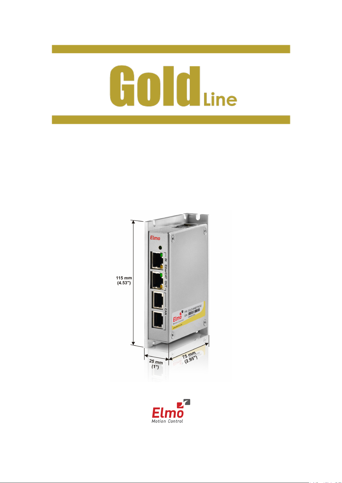
Gold Maestro
Network Motion Controller
Installation Guide
January 2013 (Ver. 1.301)
www.elmomc.com
Page 2
GOLD-MAESTRO01
13 to 96 VDC power supply
Notice
This guide is delivered subject to the following conditions and restrictions:
• This guide contains proprietary information belonging to Elmo Motion Control Ltd.
Such information is supplied solely for the purpose of assisting users of the Gold
Maestro servo drive in its installation.
• The text and graphics included in this manual are for the purpose of illustration and
reference only. The specifications on which they are based are subject to change
without notice.
• Information in this document is subject to change without notice.
Elmo Motion Control and the Elmo Motion Control logo are
registered trademarks of Elmo Motion Control Ltd.
EtherCAT Conformance Tested. EtherCAT® is a registered
trademark and patented technology, licensed by Beckhoff
Automation GmbH, Germany.
Document no. MAN-GOLD-MAESTRO-IG (Ver. 1.301)
Copyright 2013
Elmo Motion Control Ltd.
All rights reserved.
Catalog Number
GOLD-MAESTRO02 20 to 196 VDC power supply
Revision History
Version Date Details
Ver. 1.0 6th May 2010 Initial Release
Ver. 1.1 13th May 2010 Minor updates
Ver. 1.2 July 2010 Updates to Chapter 3 and Chapter 4 (Appendix)
Ver. 1.300 Oct. 2012 Updates to Chapter 3 and minor updates in other
Ver. 1.301 January 2013 Added a caution and recommendation on the
chapters.
type of cleaning solution to use for the Elmo unit.
Page 3

Elmo Worldwide
Head Office
Elmo Motion Control Ltd.
60 Amal St., P.O. Box 3078, Petach Tikva 49516
Israel
Tel: +972 (3) 929-2300 • Fax: +972 (3) 929-2322 • info-il@elmomc.com
North America
Elmo Motion Control Inc.
42 Technology Way, Nashua, NH 03060
USA
Tel: +1 (603) 821-9979 • Fax: +1 (603) 821-9943 • info-us@elmomc.com
Europe
Elmo Motion Control GmbH
Hermann-Schwer-Strasse 3, 78048 VS-Villingen
Germany
Tel: +49 (0) 7721-944 7120 • Fax: +49 (0) 7721-944 7130 • info-de@elmomc.com
China
Elmo Motion Control Technology (Shanghai) Co. Ltd.
Room 1414, Huawen Plaza, No. 999 Zhongshan West Road, Shanghai (200051)
China
Tel: +86-21-32516651 • Fax: +86-21-32516652 • info-asia@elmomc.com
Asia Pacific
Elmo Motion Control APAC Ltd.
B-601 Pangyo Innovalley, 621 Sampyeong-dong, Bundang-gu, Seongnam-si, Gyeonggi-do,
South Korea (463-400)
Tel: +82-31-698-2010 • Fax: +82-31-801-8078 • info-asia@elmomc.com
Page 4

MAN-GOLD-MAESTRO-IG (Ver . 1.301)
Table of Contents
Gold Maestro Installation Guide
Chapter 1: Safety Information ...................................................................................... 6
1.1. Cautions ......................................................................................................................6
1.2. Directives and Standards ............................................................................................7
1.3. Warranty Information ................................................................................................7
Chapter 2: Product Description .................................................................................... 8
2.1. Description .................................................................................................................8
2.2. Specifications ..............................................................................................................9
2.2.1. Gold Maestro Hardware ..............................................................................9
2.2.2. Gold Maestro Software ............................................................................ 10
2.3. Communication Options .......................................................................................... 12
2.4. How to Use this Guide ............................................................................................. 12
Chapter 3: Installation ............................................................................................... 13
4
3.1. Before You Begin ..................................................................................................... 13
3.1.1. Site Requirements .................................................................................... 13
3.1.2. Working Environment ............................................................................... 13
3.2. Unpacking the Components .................................................................................... 13
3.3. Connectors............................................................................................................... 14
3.3.1. Connector Types ....................................................................................... 14
3.3.2. Pinouts ...................................................................................................... 15
3.3.2.1. Power Connector ..................................................................... 15
3.3.2.2. EtherCAT In Connector ............................................................ 16
3.3.2.3. EtherCAT Out Connector ......................................................... 16
3.3.2.4. CAN Connectors ....................................................................... 17
3.3.2.5. Ethernet Connector ................................................................. 17
3.3.2.6. USB 2.0 Connector ................................................................... 18
3.4. Mounting the Gold Maestro .................................................................................... 18
3.4.1. Wall Mount ............................................................................................... 18
3.4.2. Surface Mount .......................................................................................... 20
3.4.3. Installation on a DIN Rail .......................................................................... 20
3.5. Connecting the Cables ............................................................................................. 21
3.5.1. Wiring the Gold Maestro .......................................................................... 21
3.5.2. Connecting the DC Power Supply ............................................................. 22
3.5.3. Ethernet .................................................................................................... 23
3.5.4. USB 2.0 Communication ........................................................................... 24
3.5.5. CAN Communication ................................................................................ 25
3.5.6. EtherCAT Communication ........................................................................ 27
3.6. Powering Up ............................................................................................................ 28
3.7. Initializing the System .............................................................................................. 28
Chapter 4: Technical Specifications ............................................................................ 29
Page 5

MAN-GOLD-MAESTRO-IG (Ver . 1.301)
Gold Maestro Installation Guide Table of Contents
4.1. Gold Maestro Dimensions ....................................................................................... 29
4.2. General Specifications ............................................................................................. 29
4.3. Environmental Conditions ....................................................................................... 29
4.4. Power Supply ........................................................................................................... 30
4.5. Communications ...................................................................................................... 30
4.6. Compliance with Standards ..................................................................................... 31
5
Page 6
MAN-GOLD-MAESTRO-IG (Ver . 1.301)
Chapter 1: Safety Information
Warning:
Caution:
Gold Maestro Installation Guide
In order to achieve the optimum, safe operation of the Gold Maestro Multi-Axis Controller, it is
imperative that you implement the safety procedures included in this installation guide. This
information is provided to protect you and to keep your work area safe when operating the
Gold Maestro and accompanying equipment.
Please read this chapter carefully before you begin the installation process.
Before you start, ensure that all system components are connected to earth ground. Electrical
safety is provided through a low-resistance earth connection.
To avoid any potential hazards that may cause severe personal injury or damage to the product
during operation, keep all covers and cabinet doors shut.
The following safety symbols are used in this manual:
This information is needed to avoid a safety hazard, which might cause
bodily injury.
6
This information is necessary for preventing damage to the product or
to other equipment.
1.1. Cautions
• The Gold Maestro must be connected to an approved 24 VDC power supply through a
line that is separated from hazardous line voltages using reinforced or double
insulation in accordance with approved safety standards.
• Before switching on the Gold Maestro, verify that all safety precautions have been
observed and that the installation procedures in this manual have been followed.
• Do not clean any of the Gold Maestro drive's soldering with solvent cleaning fluids of
pH greater than 7 (8 to 14). The solvent corrodes the plastic cover causing cracks and
eventual damage to the drive's PCBs.
Elmo recommends using the cleaning fluid Vigon-EFM which is pH Neutral (7).
For further technical information on this recommended cleaning fluid, select the link:
http://www.zestron.com/fileadmin/zestron.comusa/daten/electronics/Product_TI1s/TI1-VIGON_EFM-US.pdf
www.elmomc.com
Page 7
MAN-GOLD-MAESTRO-IG (Ver . 1.301)
Gold Maestro Installation Guide Safety Information
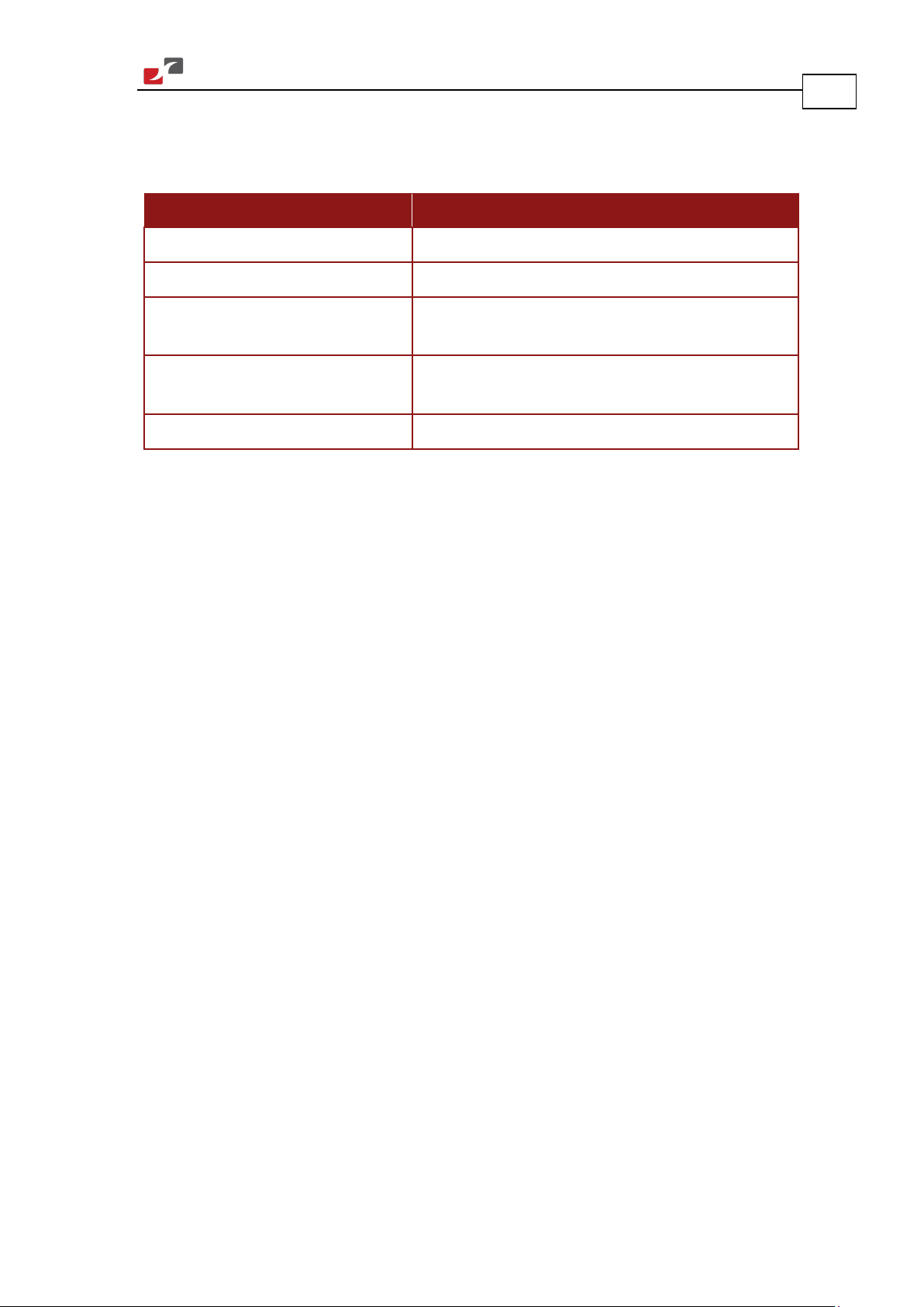
1.2. Directives and Standards
The Gold Maestro conforms to the following industry safety standards:
Safety Standard Item
Approved IEC/EN 61800-5-1, Safety Adjustable speed electrical power drive systems
Recognized UL 508C Power Conversion Equipment
In compliance with UL 840 Insulation Coordination Including Clearances and
Creepage Distances for Electrical Equipment
7
In compliance with UL 60950-1
(formerly UL 1950)
Safety of Information Technology Equipment
Including Electrical Business Equipment
In compliance with EN 60204-1 Low Voltage Directive 73/23/EEC
The Gold Maestro has been developed, produced, tested and documented in accordance with
the relevant standards. Elmo Motion Control is not responsible for any deviation from the
configuration and installation described in this documentation. Furthermore, Elmo is not
responsible for the performance of new measurements or ensuring that regulatory
requirements are met.
1.3. Warranty Information
The products covered in this manual are warranted to be free of defects in material and
workmanship and conform to the specifications stated either within this document or in the
product catalog description. The Gold Maestro is warranted for a period of 12 months from the
time of installation, or 18 months from time of shipment, whichever comes first. No other
warranties, expressed or implied – and including a warranty of merchantability and fitness for a
particular purpose – extend beyond this warranty.
www.elmomc.com
Page 8

MAN-GOLD-MAESTRO-IG (Ver . 1.301)
Chapter 2: Product Description
Gold Maestro Installation Guide
This installation guide describes the Gold Maestro Network Motion Controller and the steps for
its wiring, installation and power up. Following these guidelines ensures maximum functionality
of the system to which it is connected.
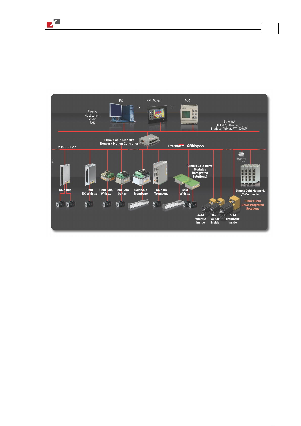
2.1. Description
The Gold Maestro is Elmo’s network motion controller. It works in a network based system in
conjunction with Elmo’s intelligent servo drives to provide a total multi-axis motion control
system solution.
The Gold Maestro is designed to support both the existing SimplIQ drives, based on standard
CAN network architecture, as well as the new Gold Line, adding EtherCAT networking.
While being a true network controller, the Gold Maestro shares the motion processing
workload with Elmo’s SimplIQ and Gold Line drives, forming a distributed motion control
system. The best servo and system performance is achieved combining the Gold Family drives,
and the new real-time motion control capabilities of the Gold Maestro controller.
8
The Gold Maestro provides:
• Full, real-time, multi-axis motion synchronization
• Advanced user programming capabilities based on the leading standards
• Time deterministic control over motion, I/Os and processes in the system
The Gold Maestro offers real-time motion control support for full multi-axis system
synchronization, using the well known industry interface PLCopen for Motion Control standard.
Various programming capabilities, such as the IEC-61131-3 standard languages, as well as
native C programming support, dramatically accelerate user level program execution. Standard
solutions were selected for ease of use.
Low level communication with drives and I/O devices over the device network uses the CAN
industry standard (DS 301, DS 401 for I/O devices, and DS 402 for drives and motion device
profiles). These are used over standard CAN networks, as well as with the new EtherCAT CoE
(CAN over EtherCAT) protocols.
Host interfaces are implemented using industry standard communications protocols, such as
Ethernet TCP/IP and higher level protocols such as Ethernet/IP and Modbus.
Standardization in protocols, definitions and APIs allows users rapid system level integration
and opens the system to third party devices on the device network.
www.elmomc.com
Page 9

MAN-GOLD-MAESTRO-IG (Ver . 1.301)
Gold Maestro Installation Guide Product Description
2.2. Specifications
2.2.1. Gold Maestro Hardware
• Hardware: Standalone
• Power Supply: Single DC supply, with two product options available:
13 VDC to 96 VDC
20 VDC to 196 VDC
• Processor: PowerPC, 333 MHz, with double precision floating point support by
hardware.
• Memory
Flash: 32 MB
RAM: 64 MB (DDR2, 333 MHz)
• Communication Hardware
Host:
• Ethernet: 1 port, Standard Ethernet, 10/100 Mbps, automatically detected
• USB: 1 port, USB2.0, 12 Mbps
Device Networks:
9
• EtherCAT: 2 x EtherCAT master ports, with redundancy support (optional)
• CAN: CANopen master port
• I/O System: All I/O interfaces are handled via the device network.
• Internal System BIT: The Gold Maestro supports internal hardware BIT (Built-in-tests)
procedures to check the system integrity level on each power up.
• Diagnostic LEDs: EtherCAT and Ethernet activity
• Dimensions: 115 mm x 75 mm x 25.4 mm (4.53" x 2.95" x 1")
• Weight: 250 g ( 8.75 oz)
• Operational Temperature: 0 °C to 40 °C
www.elmomc.com
Page 10

MAN-GOLD-MAESTRO-IG (Ver . 1.301)
Gold Maestro Installation Guide Product Description
2.2.2. Gold Maestro Software
• Operating System: Linux Operating System, with Elmo’s RT extension for real-time
motion control support
• Motion Programming and Debugging
Native C Programming, running on the target CPU. Compiling and debugging via the
Eclipse IDE using GCC under Cygwin
IEC 61131-3 with PLCopen Motion Library extension, using Elmo IDE. The following
languages are supported:
• Structured text (ST), textual
• Function block diagram (FBD), graphical
• Ladder diagram (LD), graphical
• Sequential function chart (SFC), has elements to organize programs for sequential
and parallel control processing.
• Number of Axes: Up to 96 axes, allowing mixed single axis, multiple axis and
coordinated axes motions
• Axis Types
10
Intelligent Servo Drives (Elmo), supporting both the SimplIQ and Gold lines
Operation in Numeric Control – NC - (real-time master synchronization) as well as
non-NC modes
DS 402 CoE for EtherCAT and standard DS 402 drives for CANopen
• Control System Update Rate
EtherCAT
• Cycle Update Rate: ≥ 500 µs (up to 16 axes can be updated simultaneously at a rate
of 500 µs)
• Cycle Jitter: < 1 µs, based on Master DC (Distributed Clock) support, for the full
network
CAN
• Cycle Update Rate ≥ 1 ms (CAN physical network limitations only)
• Cycle Jitter: < 100 µs for CAN Sync message initiation (actual jitter dependant on the
CAN network’s physical limitations)
• Motion Modes and Interfaces: The Gold Maestro motion interfaces use the PLCopen
Standard.
64 bit, real-time, double precision profile calculations, allowing full on-the-fly control
over speed, acceleration, deceleration and jerk
Complex motion schemes, including look-ahead optimizing of trajectory speed
calculations, for complex vector motions
Cyclic buffer for 1,000 function blocks (a buffer for 1,000 motion segments). The cyclical
buffer removes any practical limit on the number of function blocks.
• Communication Protocols
Host
• Ethernet TCP-IP/UDP for operational modes
www.elmomc.com
Page 11

MAN-GOLD-MAESTRO-IG (Ver . 1.301)
Gold Maestro Installation Guide Product Description
• Telnet communication for setup and configuration
• USB: Using binary protocol (maintenance)
• Application level: Ethernet-IP/Modbus
Device Network
• EtherCAT: CoE/EoE/FoE, supports distributed clock master
• CAN: CANopen device profiles, e.g., DS 301, DS 305, DS 402, DS 401 (I/O device
profile)
• Host and Internal Software Interface
TCP/IP interface from Host Computer. Software Library is provided for easy TCP/IP
communication interface.
Future version will also support Ethernet-IP and Modbus over the TCP-IP.
Internal Software libraries, for "C" user programs are provided, to write user code
running on the Gold Maestro target processor (native mode).
• Data Recording
4 MB data recording
Up to 32 vectors can be recorded simultaneously.
Supports more than 10 advanced triggering options and real-time scope capabilities
Very fast data upload using Ethernet
11
• Upload/Download Support
Firmware update support (Gold Maestro and drives)
System resource files
Axis parameter files
• Drive Communication Bridge Support: The Gold Maestro supports full communication
with any specific drive (EtherCAT and CAN), for the purpose of simple tuning or
configuration at the drive level, i.e. there is no need for direct communication with the
drive.
• Spatial Position-Based Pulse Generation
The Gold Maestro supports spatial (along the path) position-based pulse generation.
This is a unique feature, required for the generation of position-based events in 3D
scanning systems.
The Gold Maestro system, with Elmo’s intelligent Gold servo drives, can support single
axis and spatial enhanced position-based compare functions, resulting in trigger output
signals accurate to 1 encoder count along the trajectory path.
• Network Encoders: Supports master based motion on network encoders
• Position Error Mapping: Supports 1-D and 2-D position-based error mapping
compensation
• System Boot up Time: < 30 sec
www.elmomc.com
Page 12
MAN-GOLD-MAESTRO-IG (Ver . 1.301)
Gold Maestro Installation Guide Product Description
2.3. Communication Options
The Gold Maestro can communicate with a host PC through either a standard Ethernet port or
through USB using a binary protocol for maintenance.
The Gold Maestro communicates with its network devices using either EtherCAT or CAN
networks.
12
Figure 1: The Gold Maestro Network Connections
2.4. How to Use this Guide
This manual is part of a documentation set that can be used to set up and program the motion
of any machine whose motors are controlled by Elmo’s SimplIQ or Gold Line servo drives.
When used in conjunction with the Gold Maestro Software Manual it describes everything
needed to get the Gold Maestro up and running. Please read the safety instructions in the first
chapter before starting.
After you have successfully mounted and installed the Gold Maestro we suggest that you read
the Gold Maestro Software Manual. If you have not already done so, follow the instructions in
the Installation Guide that arrived with your servo drive, and install a drive. At least one drive
needs to be connected to the Gold Maestro in order for it to function as a motion controller.
www.elmomc.com
Page 13
MAN-GOLD-MAESTRO-IG (Ver . 1.301)
Chapter 3: Installation
Gold Maestro Installation Guide
3.1. Before You Begin
3.1.1. Site Requirements
For safe operation of the Gold Maestro make sure it is installed in an appropriate environment.
Feature Value
13
Ambient operating temperature
Maximum non-condensing humidity 90%
Operating area atmosphere No flammable gases or vapors permitted in area
0 °C to 40 °C (32 °F to 104 °F)
3.1.2. Working Environment
Warning: During operation the Gold Maestro becomes hot to the touch (the
case can heat up to 50 °C). Care should be taken when handling it.
Caution: The Gold Maestro dissipates its heat by natural convection. The
maximum ambient operating temperature must not be exceeded.
3.2. Unpacking the Components
Before you begin working with the Gold Maestro system, verify that you have all of its
components, as follows:
• The Gold Maestro multi-axis controller
• Gold Maestro software which may be downloaded from www.elmomc.com
The Gold Maestro is shipped in a cardboard box with Styrofoam protection.
To unpack the Gold Maestro:
1. Carefully remove the Gold Maestro from the box.
2. Check the Gold Maestro to ensure that there is no visible damage to the instrument. If any
damage has occurred, report it immediately to the carrier that delivered your controller.
3. To ensure that the Gold Maestro you have unpacked is the appropriate type for your
requirements, locate the part number sticker on the side of the Gold Maestro as shown
below.
www.elmomc.com
Page 14

MAN-GOLD-MAESTRO-IG (Ver . 1.301)
Gold Maestro Installation Guide Installation
4. The part number at the top gives the type designation as follows:
GOLD-MAESTRO01: 13 to 96 VDC power supply
GOLD-MAESTRO02: 20 to 196 VDC power supply
5. Verify that the Gold Maestro type is the one that you ordered.
6. Verify that you have CAN termination resistors (dongles), illustrated below.
3.3. Connectors
3.3.1. Connector Types
The Gold Maestro has the following connectors:
14
Pins Type Function
Bottom Connector
3 Phoenix 3.81 mm Pitch
Power and ground
Header
Front Connectors
8 RJ-45 EtherCAT In
8 RJ-45 EtherCAT Out
8 RJ-45 CAN1
8 RJ-45 CAN2
www.elmomc.com
Page 15
MAN-GOLD-MAESTRO-IG (Ver . 1.301)
Gold Maestro Installation Guide Installation
Pins Type Function
Bottom Connectors
8 RJ-45 Ethernet
4 USB USB
Table 1: Connector Types
3.3.2. Pinouts
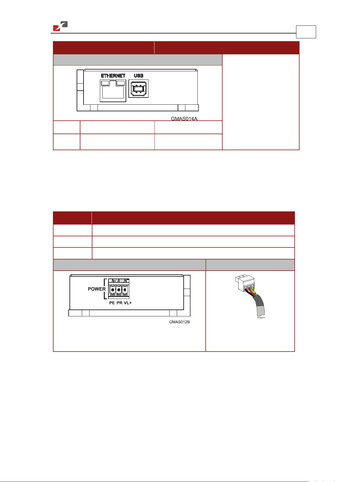
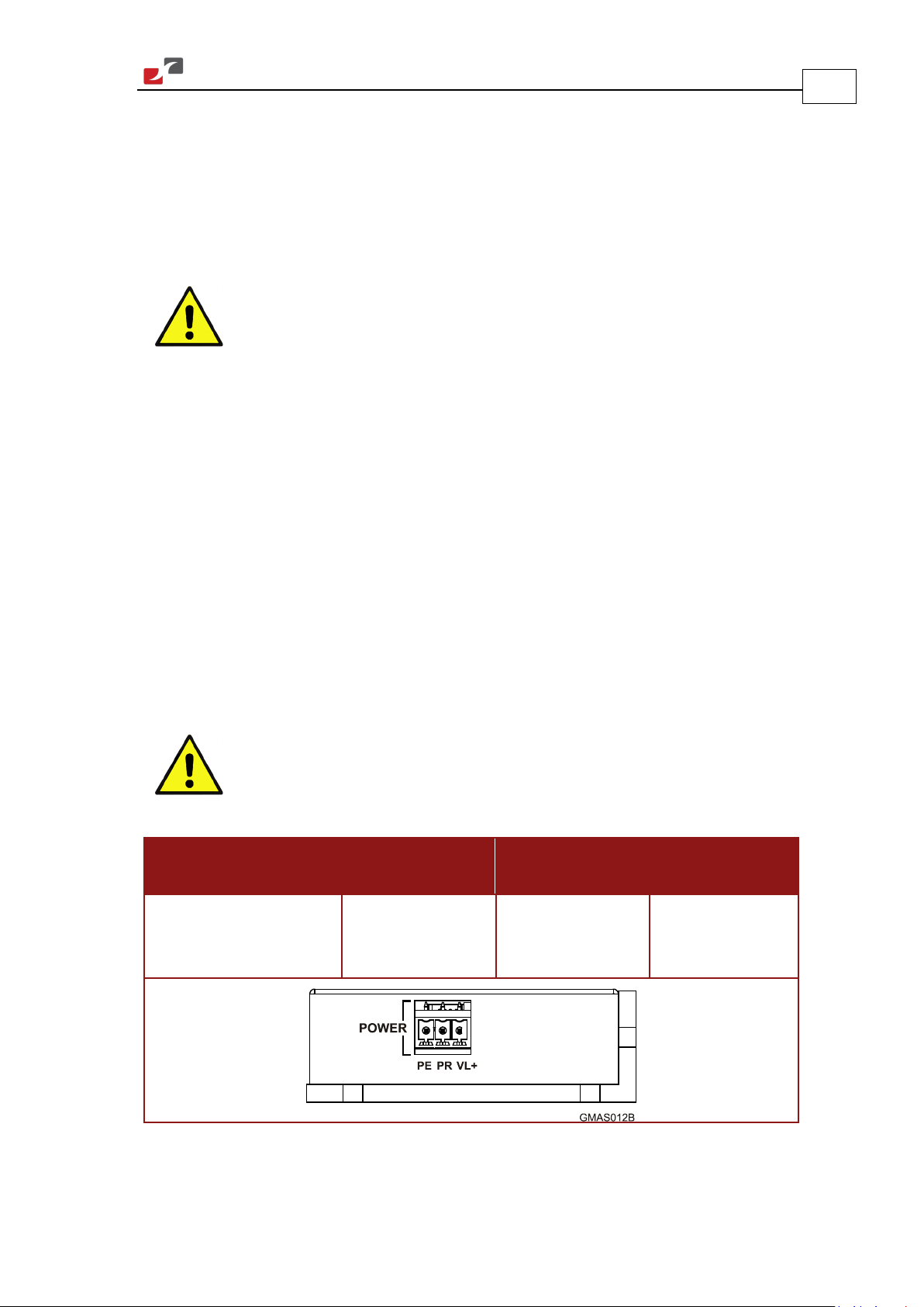
3.3.2.1. Power Connector
15
See Section 3.5.2 for full details.
Pin Function
PE Protective Earth
PR Power Return
VL+ Positive Power Input
Connector Location Cable Connector
3-Pin 3.81 mm Pitch Phoenix Header
3-Pin Phoenix Plug
(MC 1.5/3-ST-3.81)
(MC 1.5/3-G-3.81)
Table 2: Gold Maestro Power and Ground Connectors
www.elmomc.com
Page 16
MAN-GOLD-MAESTRO-IG (Ver . 1.301)
Gold Maestro Installation Guide Installation
3.3.2.2. EtherCAT In Connector
See Section 3.5.6 for full details.
Pin Signal Function
1 EtherCAT_IN/Ethernet_TX+ EtherCAT in/Ethernet transmit +
2 EtherCAT_IN/Ethernet_TX- EtherCAT in/Ethernet transmit -
3 EtherCAT_IN/Ethernet_RX+ EtherCAT in/Ethernet receive +
4,5 N/A
6 EtherCAT_IN/Ethernet_RX- EtherCAT in/Ethernet receive -
7, 8 N/A
Connector Location Cable Connector
16
8-Pin RJ-45 Connector
Standard CAT5e Ethernet Cable
Table 3: EtherCAT In Pin Assignments
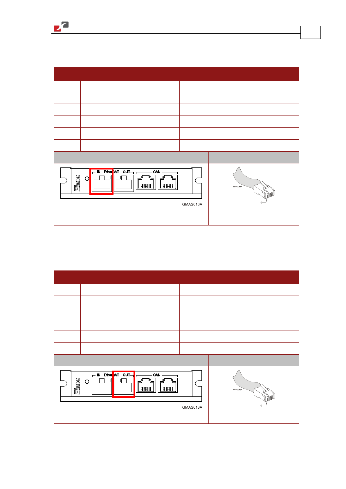
3.3.2.3. EtherCAT Out Connector
See Section 3.5.6 for full details.
Pin Signal Function
1 EtherCAT_OUT_TX+ EtherCAT in transmit +
2 EtherCAT_OUT_TX- EtherCAT in transmit -
3 EtherCAT_OUT_RX+ EtherCAT in receive +
4,5 N/A
6 EtherCAT_OUT_RX- EtherCAT in receive -
7, 8 N/A
Connector Location Cable Connector
8-Pin RJ-45 Connector
Table 4: EtherCAT Out Pin Assignments
Standard CAT5e Ethernet Cable
www.elmomc.com
Page 17
MAN-GOLD-MAESTRO-IG (Ver . 1.301)
8-Pin RJ-45 Connector
Gold Maestro Installation Guide Installation
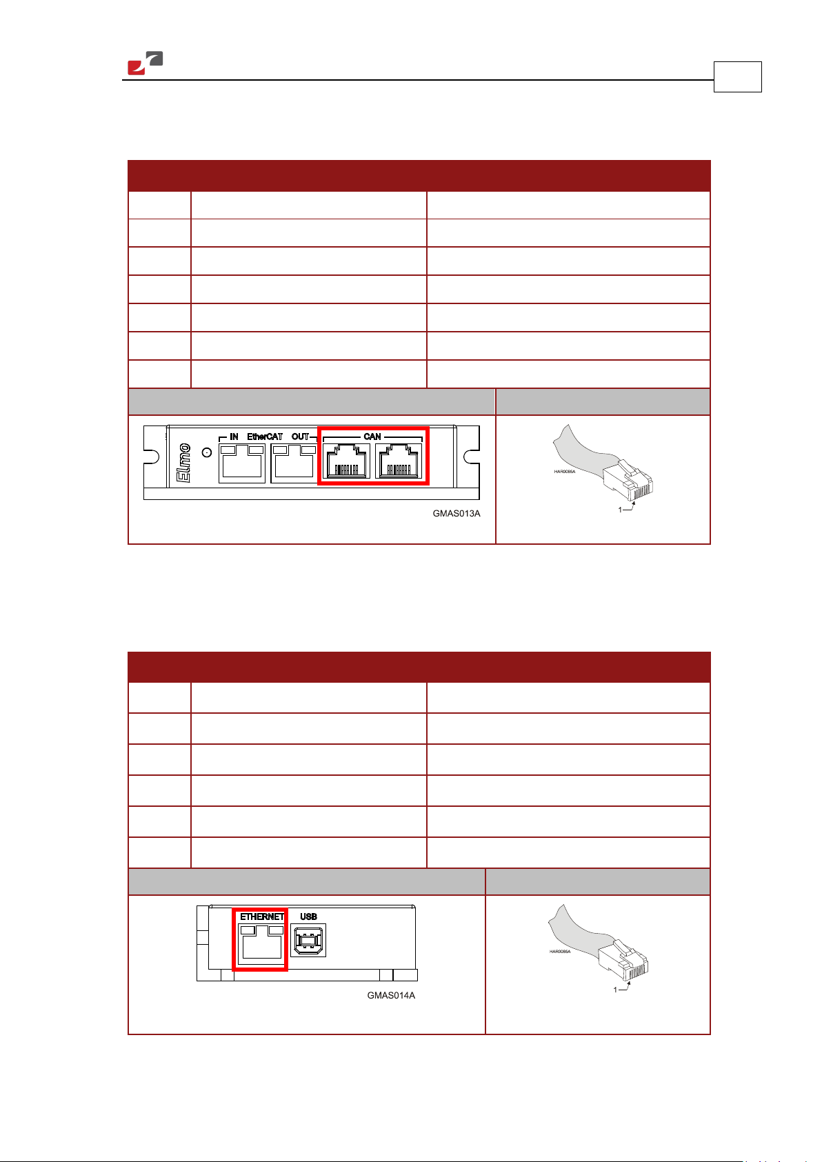
3.3.2.4. CAN Connectors
See Section 3.5.5 for full details.
Pin Signal Function
1 CAN_H CAN_H bus line (dominant high)
2 CAN_L CAN_L bus line (dominant low)
3 CAN_COMRET CAN Communication Return
4,5 N/A —
6 CAN_SHLD Shield, connected to the RJ-45 plug cover
7 CAN_COMRET CAN Communication Return
8 N/A —
Connector Location Cable Connector
17
Standard CAT5e Ethernet Cable
Table 5: CAN Pin Assignments
3.3.2.5. Ethernet Connector
See Section 3.5.3 for full details.
Pin Signal Function
1 TX+ Ethernet transmit +
2 TX- Ethernet transmit -
3 RX+ Ethernet receive +
4,5 N/A
6 RX- Ethernet receive -
7, 8 N/A
Connector Location Cable Connector
8-Pin RJ-45 Connector
Standard CAT5e Ethernet Cable
Table 6: Ethernet Pin Assignments
www.elmomc.com
Page 18

MAN-GOLD-MAESTRO-IG (Ver . 1.301)
Gold Maestro Installation Guide Installation
3.3.2.6. USB 2.0 Connector
See Section 3.5.4 for full details.
Pin Signal Function
1 USB VBUS USB VBUS from host
2 USBD- USB _N line
3 USBD+ USB _P line
4 USB COMRET USB communication return
Connector Location Cable Connector
USB 2.0 Connector
USB Device Type B Plug
18
Table 7: USB Pin Assignments
3.4. Mounting the Gold Maestro
The Gold Maestro has three mounting options:
1. Wall mount
2. Surface mount
3. Mounting on a DIN rail
3.4.1. Wall Mount
Two M4 round head screws, one through each opening in the heat sink, are used to mount the
Gold Maestro (see the diagram below) on a wall.
www.elmomc.com
Page 19

MAN-GOLD-MAESTRO-IG (Ver . 1.301)
Gold Maestro Installation Guide Installation
19
Figure 2: Wall Mounting the Gold Maestro
www.elmomc.com
Page 20

MAN-GOLD-MAESTRO-IG (Ver . 1.301)
Gold Maestro Installation Guide Installation
3.4.2. Surface Mount
Use four M4 round head screws, one through each opening in the heat sink to connect the
Gold Maestro to a surface.
20
Figure 3: Surface Mounting the Gold Maestro
3.4.3. Installation on a DIN Rail
Use one M3x5 round head screw to connect the DIN rail mounting clip to the back of the Gold
Maestro.
Figure 4: Mounting the Gold Maestro on a DIN Rail
www.elmomc.com
Page 21
MAN-GOLD-MAESTRO-IG (Ver . 1.301)
Gold Maestro Installation Guide Installation
3.5. Connecting the Cables
3.5.1. Wiring the Gold Maestro
Once the Gold Maestro is mounted, you are ready to wire the device. Proper wiring, grounding
and shielding are essential for ensuring safe, immune and optimal performance of the Gold
Maestro.
Caution: Follow these instructions to ensure safe and proper wiring.
• Use twisted pair shielded cables for communication connections. For best results, the
cable should have an aluminum foil shield covered by copper braid, and should contain
a drain wire.
The drain wire is a non-insulated wire that is in contact with parts of the cable, usually the
shield. It is used to terminate the shield and act as a grounding connection.
• Use CAT5e cables for Ethernet and EtherCAT communication.
• Keep all wires and cables as short as possible.
21
• Ensure that in normal operating conditions, the shielded wires and drain carry no
current. The only time these conductors carry current is under abnormal conditions,
when electrical equipment has become a potential shock or fire hazard while
conducting external EMI interferences directly to ground. This is in order to prevent
them from affecting the controller. Failing to meet this requirement can result in drive,
controller or host failure.
• After completing the wiring, carefully inspect all wires to ensure tightness, good solder
joints and general safety.
Caution: When the EtherCAT is connected, and FoE in operation, the USB
cable connection must be disconnected.
The following connectors are used for wiring the Gold Maestro:
Type Manufacturer &
Part No.
3.81 mm pitch
Header and Plug
Phoenix Header
MC 1.5/3-G-3.81
Mating
Connector
Phoenix Plug
(supplied)
Port
Power
PE, PR, VL+
MC 1.5/3-ST-3.81
Table 8: Gold Maestro Power and Ground Connectors
www.elmomc.com
Page 22
MAN-GOLD-MAESTRO-IG (Ver . 1.301)
Gold Maestro Installation Guide Installation
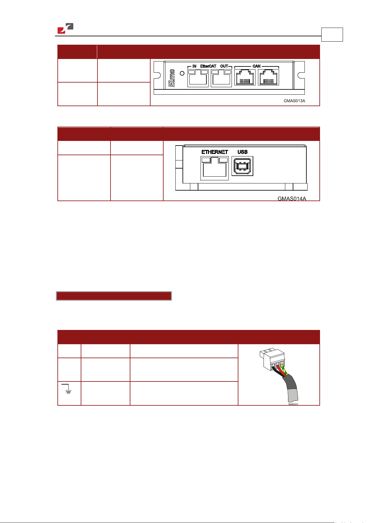
Type Port Connector Location
RJ-45 EtherCAT In/
EtherCAT Out
RJ-45 CAN x 2
Table 9: Connectors on the Front of the Gold Maestro
Type Port Connector Location
USB USB
RJ-45 Ethernet
Table 10: Connectors on the Top of the Gold Maestro
22
3.5.2. Connecting the DC Power Supply
The Gold Maestro requires 4.5 W when turned on. Any isolated power supply that can supply
that power is acceptable. The supplied power must be within the rated voltage range according
to the model: 13 V to 96 V or 20 V to 196 V.
Connect the DC output from the power supply to the power input port on the Gold Maestro
using the 3-pin power plug provided.
Notes for power supply connections:
Use a 24 AWG twisted pair shielded cable. The shield should have copper braid.
Before applying power, first verify the polarity of the connection (protected).
Pin Signal Function Pin Position
[+] VL+ DC power supply
[-] PR Power Return
PE Protective Earth
Table 11: Power Plug
www.elmomc.com
Page 23
MAN-GOLD-MAESTRO-IG (Ver . 1.301)
Gold Maestro Installation Guide Installation
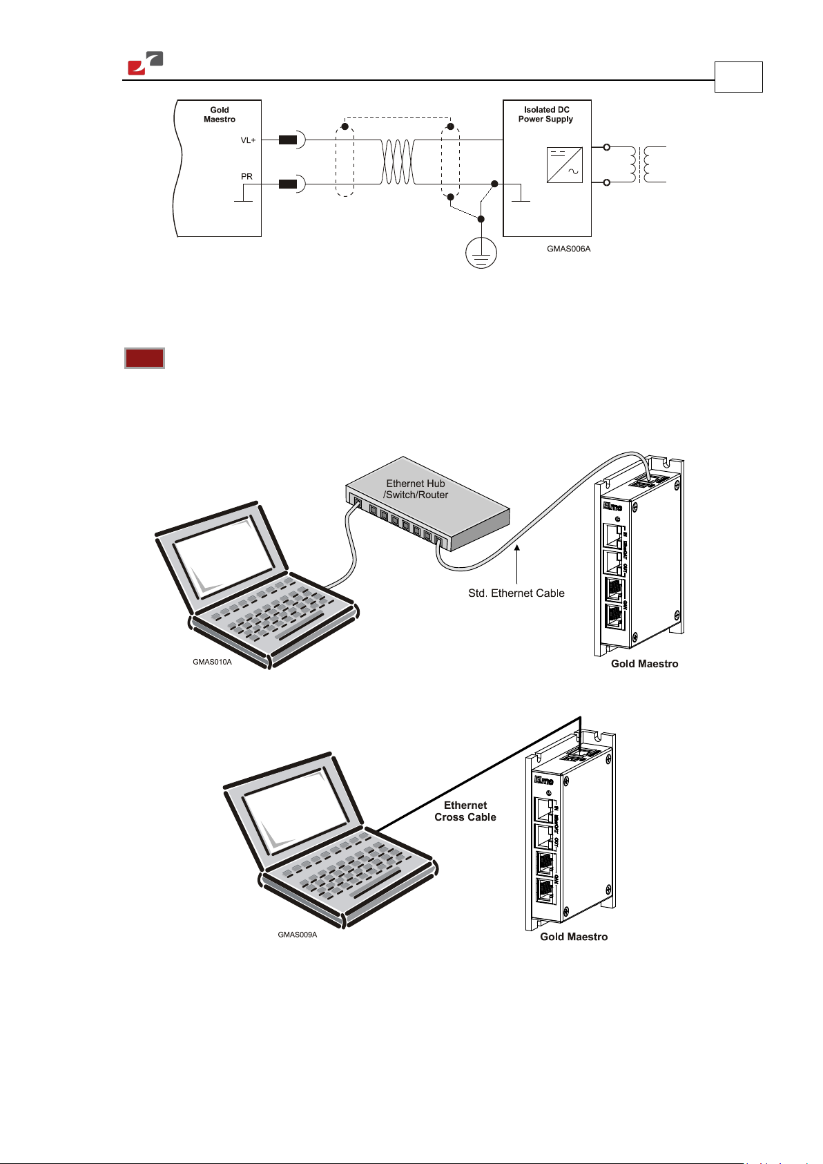
Figure 5: Power Supply Connection Diagram
3.5.3. Ethernet
Note: When connecting the Ethernet communication cable use a shielded CAT5e Ethernet
cable.
The Gold Maestro connects to a PC either directly or through a hub, switch or router. Use a
standard or cross CAT5e Ethernet cable.
23
Figure 6: Gold Maestro Connected to a Network
Figure 7: Gold Maestro Connected Peer-to-Peer to a PC
www.elmomc.com
Page 24

MAN-GOLD-MAESTRO-IG (Ver . 1.301)
Gold Maestro Installation Guide Installation
3.5.4. USB 2.0 Communication
The USB Network consists of Host controller and multiple devices. The GMAS is a USB Device.
Notes for connecting the USB communication cable:
Connect the shield to the ground of the host (PC). Usually, this connection is soldered internally
inside the connector at the PC end. You can use the drain wire to facilitate connection.
Ensure that the shield of the cable is connected to the shield of the connector used for
communications. The drain wire can be used to facilitate the connection.
Pin Signal Function
1 USB VBUS USB VBUS From Host
2 USBD- USB _N line
3 USBD+ USB _P line
4 USB COMRET USB Communication Return
24
Table 12: USB 2.0 Pin Assignments
Figure 8: USB Network Diagram
www.elmomc.com
Page 25

MAN-GOLD-MAESTRO-IG (Ver . 1.301)
Gold Maestro Installation Guide Installation
3.5.5. CAN Communication
Notes for connecting the CAN communication cable:
Use 26 or 28 AWG twisted pair shielded cables. For best results, the shield should have
aluminum foil and be covered by copper braid with a drain wire (CAT5e FTP applicable).
Connect the shield to the ground of the host (PC). Usually, this connection is soldered internally
inside the connector at the PC end. You can use the drain wire to facilitate connection.
The male RJ plug must have a shield cover.
Ensure that the shield of the cable is connected to the shield of the RJ plug. The drain wire can
be used to facilitate the connection.
Connect a 120 Ω termination resistor to each end of the network cable.
(The Gold Maestro does not have an internal terminal.)
Termination resistors should be installed in all the unused CAN ports on the Gold Maestro.
Use the CAN termination dongle supplied as a second “device end”. Simply insert the
termination resistor into the CAN connector of the second end device on the bus. This is only
possible if there are two CAN connectors.
25
Figure 9: Connecting a 120 Ω Termination Resistor to Each End of the Network Cable
www.elmomc.com
Page 26

MAN-GOLD-MAESTRO-IG (Ver . 1.301)
Gold Maestro Installation Guide Installation
Pin Signal Function Pin Position
1 CAN_H CAN_H bus line (dominant high)
2 CAN_L CAN_L bus line (dominant low)
3 CAN_COMRET CAN Communication Return
4, 5 N/A —
6 CAN_SHLD Shield, connected to the RJ plug
cover
26
7 CAN_COMRET CAN Communication Return
8 N/A —
Table 13: CAN Cable Pin Assignments
www.elmomc.com
Page 27

MAN-GOLD-MAESTRO-IG (Ver . 1.301)
Gold Maestro Installation Guide Installation
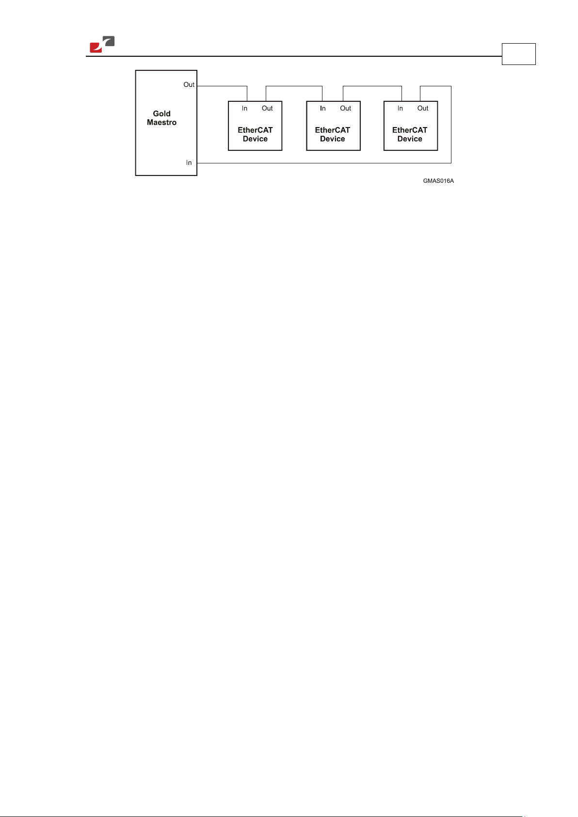
3.5.6. EtherCAT Communication
The Gold Maestro is the master of the EtherCAT network and must always be the first device in
the line.
The EtherCAT Out port of the Gold Maestro should be connected to the EtherCAT In port of the
next device down the line. The Out port of the last device in line can be left open. If
redundancy is required, the Out port of the last device should be connected to the In port of
the Gold Maestro.
Note: When connecting the EtherCAT communication cable it is recommended to use CAT5e
cable.
27
Figure 10: EtherCAT Network Example
Figure 11: EtherCAT Network with no Redundancy
www.elmomc.com
Page 28
MAN-GOLD-MAESTRO-IG (Ver . 1.301)
Gold Maestro Installation Guide Installation
Figure 12: EtherCAT Network with Redundancy
EtherCAT with redundancy is an optional method of connection.
3.6. Powering Up
After the Gold Maestro has been mounted, check that the cables are intact. The Gold Maestro
is then ready to be powered up.
3.7. Initializing the System
28
After the Gold Maestro has been connected and mounted, the system must be set up and
initialized. The minimum system requirements for a setup are:
• Gold Maestro (and power supply)
• PC with the required Elmo software
• At least one servo drive and motor
• EtherCAT cables or a terminated CAN network
• A servo drive connected through an EtherCAT cable or a CAN cable (the terminated
CAN network)
Users of SimplIQ servo drives:
Setting up the drives and motors is described in the Installation Guide for each servo drive and
in the Elmo Application Studio User Guide. Advanced features are described in the SimplIQ
Software Manual, Interlude API User Guide, SimplIQ Command Reference and CAN
Implementation Guide.
Users of Gold Line servo drives:
Setting up the drives and motors is described in the Gold Line Servo Drive Installation Guide
and Elmo Application Studio Users Guide. Advanced features are described in the Gold Line
Software Manual, Gold Line Command Reference and CAN Implementation Guide.
www.elmomc.com
Page 29

MAN-GOLD-MAESTRO-IG (Ver . 1.301)
Chapter 4: Technical Specifications
Gold Maestro Installation Guide
4.1. Gold Maestro Dimensions
29
All measurements are in mm.
4.2. General Specifications
Feature Details
Weight 250 g (8.75 ounces)
Dimensions 115 mm x 75 mm x 25.4 mm (4.53" x 2.95" x 1")
Mounting Method (with adapter) Wall Mount (“Bookshelf”)
4.3. Environmental Conditions
Feature Details
Ambient operating temperature
Storage temperature -20 °C to +85 °C ( -4 °F to +185 °F)
Maximum non-condensing humidity 90%
Protection level IP32
0 °C to 40 °C (32 °F – 104 °F)
www.elmomc.com
Page 30

MAN-GOLD-MAESTRO-IG (Ver . 1.301)
Used only for setup and determining IP address.
Gold Maestro Installation Guide Technical Specifications
4.4. Power Supply
Feature Details
Auxiliary power supply DC source only
Auxiliary supply input voltage 13 V to 96 V or
20 V to 196 V depending on the model
Auxiliary supply input power 4.5 W
4.5. Communications
Specification Details
Ethernet 100 base-T
Baud Rate: 10/100 Mbit/sec, automatically detected
CAT5e Cable
UDP, Telnet, TCP
30
USB
One port, USB 2.0, 12 Mbps
EtherCAT 100 base-T
Baud Rate: 100 Mbit/sec
CAT5e Cable
CoE, EoE, FoE
CAN CAN bus Signals:
CAN_H, CAN_L, CAN_GND
Maximum Baud Rate of 1 Mbits/sec.
CAN Profile:
DS 301
Device Profile (drive and motion control):
CAN device profiles, e.g., DS301, DS505, DS402, DS401
(for I/O)
www.elmomc.com
Page 31
MAN-GOLD-MAESTRO-IG (Ver . 1.301)
Gold Maestro Installation Guide Technical Specifications
4.6. Compliance with Standards
Specification Details
Quality Assurance
ISO 9001:2008 Quality Management
Design
Approved IEC/EN 61800-5-1, Safety Printed wiring for electronic equipment
(clearance, creepage, spacing, conductors
sizing, etc.)
MIL-HDBK- 217F Reliability prediction of electronic equipment
(rating, de-rating, stress, etc.)
31
• UL 60950
• IPC-D-275
• IPC-SM-782
Printed wiring for electronic equipment
(clearance, creepage, spacing, conductors
sizing, etc.)
• IPC-CM-770
• UL 508C
• UL 840
In compliance with VDE0160-7 (IEC 68) Type testing
Safety
Recognized UL 508C Power Conversion Equipment
In compliance with UL 840 Insulation Coordination Including Clearances
and Creepage Distances for Electrical
Equipment
In compliance with UL 60950 Safety of Information Technology Equipment
Including Electrical Business Equipment
Approved IEC/EN 61800-5-1, Safety Adjustable speed electrical power drive
systems
In compliance with EN 60204-1 Low Voltage Directive 73/23/EEC
www.elmomc.com
Page 32
MAN-GOLD-MAESTRO-IG (Ver . 1.301)
Gold Maestro Installation Guide Technical Specifications
Specification Details
EMC
Approved IEC/EN 61800-3, EMC Adjustable speed electrical power drive
systems
32
In compliance with EN 55011 Class A with
Electromagnetic compatibility (EMC)
EN 61000-6-2: Immunity for industrial
environment, according to:
IEC 61000-4-2 / criteria B
IEC 61000-4-3 / criteria A
IEC 61000-4-4 / criteria B
IEC 61000-4-5 / criteria B
IEC 61000-4-6 / criteria A
IEC 61000-4-8 / criteria A
IEC 61000-4-11 / criteria B/C
Workmanship
In compliance with IPC-A-610, level 3 Acceptability of electronic assemblies
PCB
In compliance with IPC-A-600, level 2 Acceptability of printed circuit boards
Packing
In compliance with EN 100015 Protection of electrostatic sensitive devices
Environmental
In compliance with 2002/96/EC Waste Electrical and Electronic Equipment
regulations (WEEE)
Note: Out-of-service Elmo drives should be
sent to the nearest Elmo sales office.
In compliance with 2002/95/EC
(effective July 2006)
Restrictions on Application of Hazardous
Substances in Electric and Electronic
Equipment (RoHS)
www.elmomc.com
 Loading...